Fatigue and Overloading Behavior of Steel-Concrete ... · Fatigue and Overloading Behavior of...
45
Fatigue and Overloading Behavior of Steel-Concrete Composite Flexural Members Strengthened with High Modulus CFRP Materials M. Dawood 1 , S. Rizkalla 2 and E. Sumner 3 Civil, Construction and Environmental Engineering, North Carolina State University, Raleigh, NC, 27695-7533 ABSTRACT Due to corrosion and the continuous demand to increase traffic loads, there is a need for an effective system which can be used to repair and/or strengthen steel bridges and structures. This paper describes an experimental program, recently completed, to investigate the fundamental behavior of steel-concrete composite scaled bridge beams strengthened with new high modulus carbon fiber reinforced polymer (HM CFRP) materials. The behavior of the beams under overloading conditions and fatigue loading conditions was studied as well as the possible presence of shear-lag at the interface of the steel surface and the CFRP strengthening material. The test results are compared to an analytical model based on the fundamental principles of equilibrium and compatibility, to predict the behavior of the strengthened steel- concrete composite beams. Based on the findings of this research work, combined with other work in the literature, a design guideline is proposed for the use of HM CFRP for strengthening the steel flexural members typically used for bridges and structures. 1 Graduate Research Assistant, Constructed Facilities Laboratory, North Carolina State University, 2414 Campus Shore Dr., Campus Box 7533, Raleigh, NC, 27695-7533 1/45
Transcript of Fatigue and Overloading Behavior of Steel-Concrete ... · Fatigue and Overloading Behavior of...
Fatigue and Overloading Behavior of Steel-Concrete Composite
Flexural Members Strengthened with
High Modulus CFRP Materials
M. Dawood1, S. Rizkalla2 and E. Sumner3 Civil, Construction and Environmental Engineering, North
Carolina State University, Raleigh, NC, 27695-7533
ABSTRACT
Due to corrosion and the continuous demand to increase traffic loads, there is a need for an
effective system which can be used to repair and/or strengthen steel bridges and structures.
This paper describes an experimental program, recently completed, to investigate the
fundamental behavior of steel-concrete composite scaled bridge beams strengthened with new
high modulus carbon fiber reinforced polymer (HM CFRP) materials. The behavior of the
beams under overloading conditions and fatigue loading conditions was studied as well as the
possible presence of shear-lag at the interface of the steel surface and the CFRP strengthening
material. The test results are compared to an analytical model based on the fundamental
principles of equilibrium and compatibility, to predict the behavior of the strengthened steel-
concrete composite beams. Based on the findings of this research work, combined with other
work in the literature, a design guideline is proposed for the use of HM CFRP for
strengthening the steel flexural members typically used for bridges and structures.
1 Graduate Research Assistant, Constructed Facilities Laboratory, North Carolina State
University, 2414 Campus Shore Dr., Campus Box 7533, Raleigh, NC, 27695-7533
1/45

2 Distinguished Professor of Civil Engineering and Construction, Constructed Facilities
Laboratory, North Carolina State University, 2414 Campus Shore Dr., Campus Box 7533,
Raleigh, NC, 27695-7533
3 Assitant Professor, Constructed Facilities Laboratory, North Carolina State University, 2414
Campus Shore Dr., Campus Box 7533, Raleigh, NC, 27695-7533
2/45
INTRODUCTION
The use of fiber reinforced polymer (FRP) materials has become a common practice
for the repair and strengthening of concrete structures and bridges. Due to the success of this
technique, several researchers have also investigated the use of externally bonded CFRP
materials for the repair and strengthening of steel bridges and structures. A number of
different approaches have been investigated to assess the effectiveness of using CFRP
materials for rehabilitation of steel bridge girders including repair of naturally deteriorated
girders (Mertz and Gillespie, 1996), repair of overloaded girders (Sen et al., 2001),
strengthening of undamaged girders (Tavakkolizadeh and Saadatmanesh, 2003c) and repair of
girders with simulated corrosion damage (Al-Saidy et al., 2004). Other research has been
conducted to study the fatigue durability of CFRP strengthening systems (Miller et al., 2001).
Early research focused on the use of conventional modulus CFRP materials to repair
naturally corroded bridge girders (Mertz and Gillespie, 1996). The research findings
indicated that CFRP materials can be effectively used to restore the stiffness and flexural
capacity of the damaged girders to levels comparable to those of the undamaged girders.
Researchers have also investigated the use of conventional CFRP materials to repair
steel-concrete composite bridge girders which were damaged due to severe overloading
conditions (Sen et al., 2001). The CFRP strengthening system helped to increase the nominal
capacity of the beams by up to 52 percent. The presence of the CFRP also substantially
increased the yield load and post-elastic stiffness of the strengthened beams.
In another study, three undamaged steel-concrete composite beams were strengthened
with one, three and five layers of CFRP strips respectively (Tavakkolizadeh and
Saadatmanesh, 2003c). The CFRP materials increased the nominal capacity of the
strengthened beams by up to 76 percent, however, the increase of the elastic stiffness was
3/45
minimal. In a related study, the tension flange of three other steel-concrete composite beams
were notched with a 1.3 mm wide notch at midspan to simulate 25, 50 and 100 percent loss of
the area of the tension flange (Tavakkolizadeh and Saadatmanesh, 2003b). The repair
restored the elastic stiffness and nominal capacity of the girders to levels comparable to the
undamaged beams and helped in reducing the residual deflections due to overloading
conditions.
Other researchers have simulated corrosion damage by removing a uniform portion of
the tension flange along the entire length of the girders (Al-Saidy et al., 2004). CFRP
materials were subsequently used to repair the girders. The technique restored the lost
strength of the damaged beams to levels higher than those of the undamaged girders.
However, only 50 percent of the lost stiffness of the beams was recovered.
Investigations on the fatigue durability of steel beams strengthened with CFRP
materials have been limited. Tavakkolizadeh and Saadatmanesh (2003a) demonstrated that
installation of externally bonded CFRP patches can reduce crack propagation rates and
increase the fatigue life of cracked steel members. Prestressing CFRP patches prior to
installation can help promote crack-closure effects and further extend the fatigue life of
cracked steel members (Bassetti et al., 2000). The fatigue durability of naturally corroded
steel bridge girders, which were repaired with CFRP materials, has been shown to be at least
equal to that of many typical steel details which are commonly used in current bridge
construction (Miller et al., 2001).
The majority of the previous research has focused on the use of conventional modulus
CFRP materials for the repair of steel bridge members. While substantial strength increases
have been achieved, typically a large amount of CFRP materials was required to achieve an
increase of the elastic stiffness of the beams. This is due to the relatively low modulus of
elasticity of the CFRP as compared to steel and also possibly due to the presence of shear-lag
4/45

effects between the steel beam and the CFRP materials (Tavakkolizadeh and Saadatmanesh,
2003c).
Recently, high modulus CFRP materials have become commercially available which
have a modulus of elasticity approximately twice that of conventional steel. The effectiveness
of using HM CFRP materials to repair steel bridge girders was demonstrated by testing three
large-scale steel-concrete composite beams strengthened with different configurations of HM
CFRP materials (Schnerch, 2005). The elastic stiffness and nominal moment capacity of the
beams were increased by up to 36 percent and 45 percent respectively. The testing
demonstrated that prestressing the HM CFRP strips prior to installation on the steel beam
increased the efficiency of utilization of the CFRP. Test results indicated that prestressing of
the HM CFRP required only half the amount of prestressed laminates that was required for a
similar beam strengthened with unstressed CFRP laminates to achieve a similar increase of
the stiffness. The use of prestressed laminates also helped to maintain the original ductility of
the unstrengthened member.
This paper presents the findings of an experimental investigation, recently completed,
to study the behavior of steel-concrete composite beams strengthened with HM CFRP
materials and subjected to overloading and fatigue loading conditions. The research
examined also, the possible presence of shear-lag at the interface between the steel surface
and the CFRP materials. The paper also provides an analytical model, based on equilibrium
and compatibility principles, to predict the response of steel and steel-concrete composite
flexural members strengthened with CFRP materials. A detailed description of the research
program presented in this paper is given in Dawood (2005). Based on the research findings
and the available literature review, a guideline is proposed which can be used by practitioners
to design the required HM CFRP strengthening system for a given steel-concrete composite
beam.
5/45

HM CFRP STRENGTHENING SYSTEM
The carbon fiber reinforced polymer materials used in this study consist of pitch based carbon
fibers pultruded into 4 mm thick, 100 mm wide laminates. The modulus of elasticity and
ultimate strain of the strips reported by the manufacturer were 460,000 MPa and 0.00334
respectively. The reported ultimate strain was lower than that measured in the experimental
program reported in this paper. The laminates had a fiber volume fraction of 70 percent and
were fabricated with a glass fiber peel ply on both faces to minimize the need for surface
preparation of the composite material. The strips were bonded to the tension flange of the
steel beams using a two part epoxy adhesive with a fast hardener. This adhesive was selected
from among six adhesives considered in the same research program (Schnerch, 2005). The
tension flange of the steel beam was grit blasted immediately prior to installation of the
strengthening system to remove any rust and mill scale from the surface. The surface was
subsequently cleaned by air blowing and solvent wiping. After the CFRP strips were installed
a wooden clamping system was applied for at least 12 hours until the adhesive had thoroughly
set. The adhesive was allowed to cure for at least one week prior to testing.
EXPERIMENTAL PROGRAM
The experimental program consisted of seven steel-concrete composite beams, five of which
were strengthened with full-length HM CFRP strips, to study the behavior of the proposed
HM CFRP strengthening system under the effect of overloading and fatigue loading
conditions. In the first phase three beams were tested to study the behavior of the
strengthening system under overloading conditions. The three beams tested in the second
phases were used to study the behavior under fatigue loading conditions and to investigate the
durability of the strengthening system. The effect of the adhesive thickness on the fatigue
behavior was also examined. In the third phase, the seventh beam was tested to examine the
6/45

shear-lag phenomenon at the interface of the steel surface and the CFRP materials. The
strengthened beams, tested in the first and second phase, were also used to investigate the
possible presence of shear-lag phenomenon. The tested beams were designed to represent
scaled steel-concrete composite beams which are typically used for highway bridge
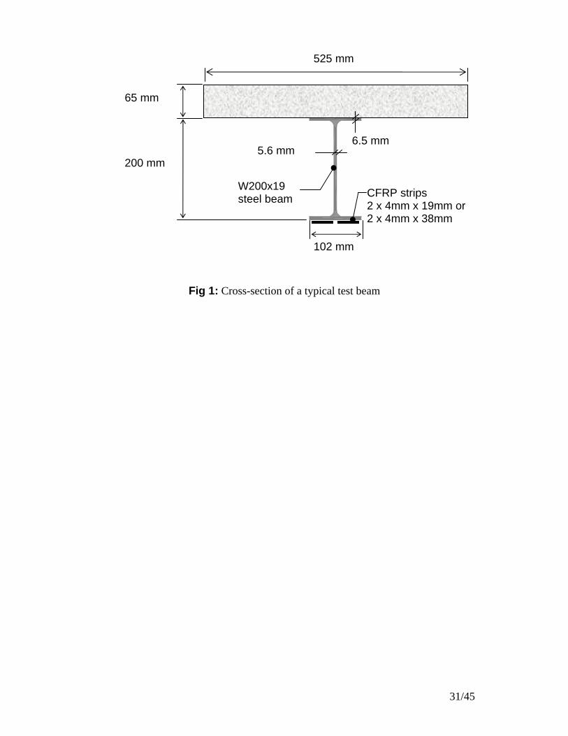
construction. The cross-section of the tested beams is shown schematically in Fig 1. The
beams were strengthened with different reinforcement ratios, ρ, of HM CFRP materials and
tested in a four point bending configuration as shown schematically in Fig 2(a) and Fig 2 (b).
A detailed description of the three phases of the experimental program is presented in
Table 1. A total of three beams were tested to investigate the behavior under overloading
conditions. Two of the test beams were strengthened with two different levels of CFRP to
investigate the effect of the CFRP reinforcement ratio on the behavior of the beams. A third
unstrengthened beam was tested to serve as a control beam for the overloading study. All
three of the beams were unloaded and reloaded at various load levels to simulate the effect of
severe overloading conditions.
The objective of the fatigue study was to verify the fatigue durability of the
strengthened beams and to assess the effect of the bond preparation on the fatigue durability
of the strengthening system. Three additional beams were tested. Two of the beams were
strengthened with the same amount of CFRP materials, however, using different bonding
techniques. The first beam was strengthened using the standard bonding procedure described
previously. The second beam was strengthened using a modified bonding technique which
included increasing the thickness of the adhesive layer which was applied in conjunction with
a primer coat of a silane adhesion promoter. The third beam remained unstrengthened and
was used as a control beam for the fatigue study. All three beams were subjected to three
million fatigue loading cycles and the load was cycled at a frequency of 3 Hz. The minimum
applied load used for the cycled loading, Pmin, was selected to be equivalent to 30 percent of
7/45

the calculated yield load of the unstrengthened beams to simulate the effect of the sustained
dead-load for a typical bridge structure. The maximum load applied, Pmax, for the
unstrengthened beam, was selected to be equivalent to 60 percent of the calculated yield load
to simulate the combined effect of dead-load and live-load. The maximum load for the two
strengthened beams, Pmax, however, was selected to be equivalent to 60 percent of the
calculated increased yield load of the strengthened beams. The resulting load range, ΔP, also
simulated an increase of 20 percent of the allowable live-load level in comparison to the
unstrengthened beam.
To simulate the actual behavior of a typical strengthened highway bridge, the two
strengthened beams that were tested in the fatigue study were subjected to a sustained
simulated dead-load prior to installation of the HM CFRP strengthening system. The
simulated dead-load was applied using an independent loading system as shown in Fig 3.
Prior to installation of the CFRP, the simulated dead-load of 50 kN was applied by tightening
the nuts against the load cells on the threaded rods. The simulated dead-load was sustained on
the beams while the CFRP strips were installed and during the curing process of the adhesive.
After the adhesive cured, the load was transferred from the independent dead-load system to
the hydraulic actuator and the fatigue loading program was commenced.
The seventh beam, tested in the third phase, was tested under monotonic loading
conditions up to failure to investigate the shear-lag phenomenon independent of the effect of
overloading or fatigue loading conditions. The strain measurements of the four strengthened
beams, tested in the first and second phases, were also used to examine the shear-lag
phenomenon.
The tensile yield strength and modulus of elasticity of the steel beams were
determined by standard coupon tests and were found to be 380 MPa and 200,000 MPa
respectively. The compressive strength of the concrete, used for the concrete deck slabs for
8/45

the seven test beams, was determined from standard cylinder tests after 28 days. The
measured concrete cylinder strengths for the deck slabs used for the different test beams are
given in Table 1.
All of the test beams were instrumented to measure deflections at midspan and at the
support locations. All of the test beams were also instrumented to measure strain at several
depths along the midspan cross-section. The two strengthened beams which were tested in
the fatigue study, were also instrumented to measure strain at the quarter-span cross-section.
The measured strains were used to construct the strain profiles for the strengthened beams to
investigate the shear-lag phenomenon at the interface between the steel surface and the CFRP
materials.
EXPERIMENTAL RESULTS
This section presents and discusses the test results of each of the three phases considered in
the experimental program and summarizes the relevant research findings.
Overloading Study
The load-deflection relationships of the three beams that were tested to study the overloading
behavior of the strengthened beams are presented in Fig 4. The behavior of the control beam,
beam ST-CONT, is given in Fig 4(a) while the behavior of the other two beams, strengthened
with 4.3 and 8.6 percent reinforcement ratios of HM CFRP, are given in Fig 4(b) and Fig 4(c)
respectively. All three beams were unloaded and reloaded at various loading stages to
simulate the effect of overloading conditions.
In general, the load-deflection behavior of the three beams was essentially linear up to
yielding of the steel. Prior to yielding of the steel all three of the tested beams exhibited
minimal residual deflections upon removal of the applied load.. Reloading resulted in
minimal hysteresis in all cases. After yielding of the steel, the unstrengthened beam exhibited
9/45
a significant increase of the measured residual deflection, as shown in Fig 4(a), while the two
strengthened beams continued to exhibit minimal residual deflections up to rupture of the
CFRP. A typical rupture failure of the HM CFRP laminates is shown in Fig 4(d). After
rupture of the CFRP occurred, the load-deflection response of the strengthened beams
followed a similar trend to that measured for the unstrengthened beam. The tests indicate that
the nominal capacity of the unstrengthened beam, ST-CONT, was governed by crushing of
the concrete while the nominal capacity for the two strengthened beams, OVL-1 and OVL-2
was governed by rupture of the CFRP.
The increases of the elastic stiffness, yield load and nominal strength of the two
strengthened beams are presented in Table 2. The elastic stiffness, yield load and nominal
capacity of the beams were increased by 46 percent, 85 percent and 66 percent respectively
using the higher reinforcement ratio. Inspection of Table 2 indicates that doubling the CFRP
reinforcement ratio, from 4.3 percent to 8.6 percent, approximately doubled the elastic
stiffness increase of the beams. Doubling the reinforcing ratio also approximately tripled the
increase of the measured yield load and nominal capacity of the strengthened beams. This
demonstrates that increasing the reinforcement ratio increases the efficiency of the CFRP
material.
In addition to the increase of the stiffness and strength, use of the HM CFRP materials
also helped to reduce the residual deflection of the strengthened beams due to possible
overloading conditions of the beams. To evaluate the effectiveness of the HM CFRP
strengthening system, each of the three beams was unloaded at a load level of 175 kN to study
the behavior under possible overloading conditions. This load is equivalent to the allowable
service load for the beam strengthened with the higher HM CFRP reinforcement ratio of 8.6
percent and induced a strain level of 60 percent of the yield strain of the steel, εy, as
determined from the coupon tests. The average measured strain at the steel tension flange at
10/45

this load level was 2.5 εy, 1.0 εy and 0.6 εy for beams ST-CONT, OVL-1 and OVL-2
respectively. The beams were unloaded to a load level of 45 kN which simulates an
equivalent sustained load acting on a typical bridge after an overloading event due to the
effect of self-weight and superimposed dead-load. The plastic residual deflection, at the
45 kN load level for beams OVL-1 and OVL-2 were respectively 20 percent and 15 percent of
the measured residual deflection of beam ST-CONT. Consequently, under severe overloading
conditions, an unstrengthened beam may require replacement while a strengthened beam may
remain in excellent service condition.
Fatigue Study
Three beams were tested in the fatigue study. Beams FAT-1 and FAT-1b were strengthened
with 4.3 percent reinforcement ratio of CFRP using two different bonding techniques while
beam FAT-CONT remained unstrengthened to serve as a control beam for the fatigue study.
The two strengthened beams were tested under an equivalent load to simulate a 20 percent
increase of the applied live load as compared to the unstrengthened beam. All three beams
sustained a three million-cycle fatigue loading course without exhibiting any indication of
failure. The degradation of the stiffness and mean deflection of the three beams throughout
the three million-cycle loading course are shown in Fig 5(a) and (b) respectively. The
stiffnesses and mean deflections presented in the figure are normalized with respect to the
measured initial values at the beginning of the fatigue loading program.
All three of the tested beams exhibited a minimal degradation of the elastic stiffness of
less than 5 percent throughout the three million fatigue loading cycles as shown in Fig 5(a).
However, the unstrengthened beam FAT-CONT exhibited nearly a 30 percent increase of the
mean deflection due to the applied fatigue cycles. This behavior was most likely due to the
fatigue-creep behavior of the concrete deck slab. Both of the strengthened beams exhibited
11/45

superior performance with a maximum increase of the measured mean deflection of
10 percent. The observed degradation of the two strengthened beams throughout the three
million fatigue cycles was similar. This indicates that neither the bonding procedure nor the
adhesive thickness affected the fatigue behavior of the strengthening system.
After the completion of the fatigue program, the three beams were loaded
monotonically to failure. The load-deflection behavior of the beams followed a similar trend
to the observed load-deflection envelope of the three beams that were tested in the
overloading study. The nominal capacity of the two strengthened beams, FAT-1 and FAT-1b,
was governed by rupture of the CFRP at a load of 250 kN. After rupture of the CFRP, the
load-deflection behavior of the two beams followed a similar trend to the load-deflection
behavior of the unstrengthened beam, FAT-CONT. Crushing of the concrete for all three
beams occurred at a measured load of between 200 kN and 215 kN. The findings of the
fatigue study demonstrate that the strengthened beams can sustain the specified increase of the
live load level for the selected HM CFRP reinforcement ratio while maintaining a level of
durability which was comparable to that of the unstrengthened beam.
Shear-lag Study
One additional beam, SHL, was tested to investigate the possible presence of a shear-lag
phenomenon at the interface of the steel surface and the CFRP materials under monotonic
loading conditions. The beam was strengthened with 8.6 percent reinforcement-ratio of HM
CFRP. The load-deflection behavior of beam SHL was essentially the same as the load-
deflection envelope of beam OVL-2, shown in Fig 4(c), which was strengthened with the
same reinforcement ratio of HM CFRP.
The measured strain profiles at midspan of beams SHL and OVL-2, immediately prior
to rupture of the HM CFRP material, are shown in Fig 6. The measured strain profiles for
12/45

both beams indicate a slight discontinuity of the strain profile at the interface of the bottom
surface of the steel tension flange and the CFRP material. However, the opposite sign of the
discontinuity suggests that the discontinuity is not due to the presence of a shear lag effect.
The measured discontinuity is likely due to the effect of residual stresses in the steel beam
during the manufacturing process or due to possible local instability and lateral movement of
the tension flange of the steel beam during the test. The presence of these effects was
confirmed by independent strain measurements at different locations along the steel tension
flange of the strengthened and unstrengthened test beams. The measured strain profiles for
the remaining three strengthened test beams, OVL-1, FAT-1 and FAT-1b, were essentially
linear and exhibited minimal discontinuities between the steel and the CFRP. The findings of
the shear-lag study indicate that the effect of shear-lag is negligible and the plane sections
remain plane assumption is appropriate for the analysis of the strengthened beams.
ANALYTICAL MODEL
The analytical model proposed to predict the load-deflection behavior of the strengthened
steel-concrete composite beams is based on equilibrium and compatibility. The model
considers the non-linear material characteristics of the steel and the concrete and assumes
linear-elastic behavior for the CFRP materials. The procedure is described briefly below and
is presented in detail elsewhere (Dawood, 2005; Schnerch, 2005; Schnerch et al., 2006).
The moment-curvature behavior for a given cross-section is determined based on a
selected strain at the top level of the compression flange and iteration of the neutral axis depth.
For a given strain at the top surface of the concrete deck, and an assumed neutral axis depth,
the strain at any level in the cross-section can be calculated using an assumed linear strain
profile. The known material characteristics can be used to calculate the stress distribution
throughout the cross section. The internal forces are calculated by integration of the stress
13/45

profile. The neutral axis depth can then be determined through iteration until horizontal force
equilibrium is satisfied and the corresponding moment and curvature of the section can be
calculated for the given strain level. The strain at the top of the section is incremented to
establish the complete moment-curvature relationship of the section. For a given loading and
support configuration the load deflection behavior of the beam can be determined by
integration of the curvature profile using any commonly accepted method.
The nominal capacity of the strengthened section is limited by rupture of the CFRP
which occurs when the strain at the level of the CFRP approaches the maximum value. After
rupture of the CFRP the behavior of the beam can be described by considering the
unstrengthened section up to crushing of the concrete deck slab. The model assumes that the
capacity of the adhesive joint is adequate to develop the full tensile capacity of the CFRP
materials and, consequently, debonding is not considered as a possible mode of failure. An
independent analytical model which can be used to determine the shear and normal bond
stresses in the adhesive joint of a strengthened beam is presented in a separate paper by
Schnerch (2005).
Validation of the Analytical Model
The accuracy of the analytical model was verified by comparing the predicted load-deflection
response to the measured values obtained from the experimental program. The material
properties to be input into the analytical model were determined by testing of representative
material samples. The load-deflection response of the strengthened test beams was predicted
and compared to the measured values obtained from the experimental program.
The material properties of the concrete deck slabs for the five beams were determined
by testing representative concrete cylinders. The complete stress-strain relationship of the
cylinders was measured and a best fit curve to the measured data was established using the
14/45
equation presented in Fig 7 (Collins and Mitchell, 1997) where fc is the stress in the concrete
corresponding to a strain, ε; εc’ is the strain corresponding to the peak concrete stress, fc’; n is
a curve fitting factor and k is a post peak decay factor. The measured stress-strain
relationships for the cylinder tests, as well as the best fit curves for all three batches of
concrete are presented in Fig 7. The material characteristics used for the concrete material
model are presented in Table 3. The longitudinal steel reinforcement in the concrete slab was
modeled using an elastic-plastic relationship with an elastic modulus of 200,000 MPa and a
yield strength of 400 MPa.
The modulus of elasticity and yield strength of the structural steel W-sections were
determined from representative coupon tests as 200,000 MPa and 380 MPa as discussed
previously. However, all of the beams that were tested in the experimental program exhibited
an earlier deviation from the elastic behavior due to the presence of residual stresses which
was not observed in the coupon tests. A tri-linear material model was used to account for the
gradual yielding of the steel in the beam tests due to the presence of residual stresses as shown
in Fig 8 (Englekirk, 1994). The proportional limit strain, εp, for the steel was determined
from the measured strain at the tension flange of the steel beams that were tested in the
experimental program. The measured load-strain relationship at the tension flange of the
beams became non-linear at a measured strain of approximately 0.0016. Consequently, this
value was selected as the proportional limit strain for the material model.
The HM CFRP laminates were modeled as a linear-elastic material to failure using the
elastic modulus of 460,000 MPa reported by the manufacturer and the average measured
strain at rupture of the CFRP strips of 0.0037 from the beam tests.
The predicted and measured load deflection responses based on the proposed model
and the measured values for beams OVl-1, OVL-2, FAT-1 and FAT-1b are compared in Fig 9.
15/45

Inspection of Fig 9 indicates that the analytical model closely predicts the load-deflection
behavior of the strengthened beams prior to rupture of the CFRP. The predicted response of
the unstrengthened beams closely matches the measured behavior after rupture of the HM
CFRP laminates. The measured and predicted nominal capacity and elastic stiffness increase
for each of the five beams are given in Table 4. In all cases the analytical model accurately
predicted the nominal capacity and elastic stiffness increase of the strengthened beams to
within 10 percent of the measured values.
The analytical model was also used to predict the nominal moment capacity of the
tested beams for a number of different reinforcement ratios of CFRP up to 40 percent to
establish practical limits for the amount of strengthening which can be applied to a given
cross-section. The relationship between the reinforcement ratio and the nominal moment
capacity of the strengthened beams is presented in Fig 10 for the specific cross-section
considered in the current test program. The test results of the five strengthened beams that
were tested in the experimental program are also plotted for reference purposes. From the
figure, it can be seen that the relationship is essentially tri-linear and the figure can be
separated into three distinct regions. The first region includes reinforcement ratios up to
1.5 percent which corresponds to installing a 100mm wide x 0.5 mm thick CFRP strip on the
tension flange of the steel beam. This represents a very under-reinforced section for which
rupture of the CFRP occurs prior to achieving the nominal strength of the unstrengthened
section, Mn,US. Within this region installation of the CFRP does not increase the nominal
capacity of the section. As such, this represents a practical lower limit of effectiveness for the
allowable amount CFRP strengthening which should be applied to the beam.
For reinforcement ratios from 1.5 percent to 20 percent the nominal capacity of the
section is governed by rupture of the CFRP prior to crushing of the concrete. Increasing the
reinforcement ratio within this region results in a corresponding increase of the nominal
16/45

capacity of the strengthened section, Mn,S up to 2.6 times the nominal capacity of the
unstrengthened member. All of the tested beams fall within this region as indicated in Fig 10.
The failure of the section by rupture of the CFRP in this region indicates full utilization of the
capacity of the CFRP materials.
The third region includes sections with a reinforcement ratio of CFRP greater than
20 percent. This corresponds to installing a 100mm wide x 7 mm thick CFRP strip on the
tension flange of the beam. In this region failure of the section occurs due to crushing of the
concrete prior to rupture of the CFRP. The slight increase of the strength in this region is
mainly due to the shift of the neutral axis by increasing the amount of CFRP applied to the
beam. This represents a practical upper limit for the reinforcement of the cross-section in this
study. From the figure it can be seen that increasing the reinforcement ratio beyond this limit
does not significantly increase the nominal capacity of the section indicating inefficient
utilization of the CFRP strengthening materials.
While the relationship shown in Fig 10 and the limits discussed above are for the
specific beam cross-section considered in this study, a similar behavior can be expected for
most typical bridge girders which consist of a relatively slender steel-section and a typical
reinforced concrete deck. Similar limits can be easily established for any steel-concrete
composite beam configuration using the presented analytical model.
DESIGN GUIDELINES
Based on the findings of this research program a series of design guidelines have been
developed and proposed for the design of HM CFRP strengthening for steel-concrete
composite beams. A detailed description of the proposed flexural design procedures is given
by Schnerch et al. (2006).
17/45

The design procedure requires that the increase of live load for a steel-concrete
composite beam strengthened with HM CFRP materials should satisfy three criteria. These
three criteria are shown in Fig 11 with respect to the moment-curvature response of a typical
strengthened beam. Due to the presence of the additional layer of HM CFRP material, the
yield moment of the strengthened beam, MY,S , is greater than the yield moment of the same
beam prior to strengthening, MY,U. This was verified by the findings of several experimental
studies (Dawood, 2005; Schnerch, 2005). It should be noted that the increase of the yield
moment due to installation of the HM CFRP strengthening system is highly dependent on the
level of the dead load acting on the member prior to installation of the strengthening. To
ensure that the strengthened beam remains elastic under service loading conditions, the total
applied moment acting on the strengthened section, including the effect of dead load, MD, and
the increased live-load, ML, should not exceed 60 percent of the increased yield moment of
the strengthened section. To satisfy the strength limit state, the total factored moment based
on the appropriate dead-load and live-load factors, αD and αL respectively, should not exceed
the ultimate moment capacity of the strengthened section, MU,S. Also, to ensure that the
structure remains safe in the case of possible loss of the strengthening system, the total
applied moment, including the effect of dead-load and the increased live-load should not
exceed the residual nominal moment capacity of the unstrengthened section, Mn,US. The
fatigue life of the strengthened member under the effect of the increased live load level should
be checked to be within the allowable stress range specified by the applicable design codes.
The findings of the fatigue study demonstrate that the fatigue durability of the strengthening
system under an increased live load inducing a stress range at the tension flange of the steel
beam of 30 percent of the yield strength of the steel, was comparable to that of an
unstrengthened beam which was tested using the same stress range
18/45

While the nominal behavior of the member can be used to predict the behavior under
service loading conditions, the design ultimate capacity should incorporate suitable reduction
factors to ensure that the member remains safe. Due to the statistical uncertainty of the
measured ultimate capacity of the HM CFRP materials, the mean strength of the CFRP
reported by the manufacturer, FRP,uf , should be reduced by 3 times the standard deviation, σ,
when calculating the ultimate capacity of the strengthened section (ACI 440.2R, 2002). To
account for possible environmental degradation of the CFRP materials, an environmental
degradation factor, CE should also be implemented (ACI 440.2R, 2002). Therefore, the
design strength of the HM CFRP material can be calculated as
)3f(Cf uFRP,EuFRP, σ−= Equation (1)
Based on the current guidelines of the American Concrete Institute it is proposed that an
environmental degradation factor of 0.85 be considered for CFRP materials under outdoor
exposure conditions (ACI 440.2R, 2002).
The design failure strain of the CFRP material, εFRP,u can be calculated using the
calculated design strength of the CFRP and the average elastic modulus, EFRP, reported by the
manufacturer.
The nominal capacity of a steel-concrete composite beam strengthened with high
modulus CFRP materials is typically governed by rupture of the CFRP materials which
occurs in a sudden, brittle manner without significant warning. To account for the brittle
nature of failure, a strength reduction factor, φ, of 0.75 is recommended. This reduction factor
is consistent with the reduction used in the American Institute of Steel Construction (AISC)
19/45

LRFD Specification (2001) for rupture type limit states. The design ultimate capacity of the
strengthened beam, MU,S should thus be calculated as φMn,S.
CONCLUSIONS
This paper presents details of an experimental program which was undertaken to investigate
the fundamental behavior of steel-concrete composite beams strengthened using high modulus
CFRP materials. The findings of the experimental program provide comprehensive evidence
that HM CFRP materials can be used to increase the elastic stiffness, yield load and nominal
capacity of steel flexural members which are typically used for most highway bridge
structures. The presence of the CFRP helps to reduce the residual deflection due to
overloading conditions which can help reduce or eliminate the need for repair or replacement
of a structure. The tested strengthened beams where able to sustain three million loading
cycles with a 20 percent increase of the simulated live load level. The beams exhibited
similar performance to a control beam which was tested at a lower loading range. Further,
using thicker adhesive and a silane adhesion promoter did not appear to affect the fatigue
behavior of the strengthening system. Based on the measured strain profiles of the five
strengthened beams which were investigated in the shear-lag study, the effect of shear-lag
between the steel beam and the CFRP materials is minimal.
An analytical model is also presented which is based on a moment-curvature analysis
and satisfies the conditions of equilibrium and compatibility. The model accurately predicted
the load-deflection response, the nominal capacity and the elastic stiffness increase of the
tested beams.
20/45
Based on the findings of the research program a series of design guidelines are
presented which can be used to design the required HM CFRP strengthening for a steel-
concrete composite beam. The allowable live load increase for a strengthened beam should
satisfy three conditions. Particularly,
(i) MD + ML ≤ 0.6 MY,S
(ii) αD MD + αL ML ≤ MU,S
(iii) MD + ML ≤ Mn,U
The findings of this research demonstrate that externally bonded HM CFRP materials
represent an effective strengthening system for steel-concrete composite highway bridge
girders.
Acknowledgements
The authors would like to acknowledge the support provided by the National Science
Foundation (NSF) Industry/University Cooperative Research Center (I/UCRC) for the Repair
of Buildings and Bridges with Composites (RB2C) and the support provided by Mitsubishi
Chemical FP America Inc.
NOTATION
The following symbols are used in this paper:
CE = environmental reduction factor
fc = concrete stress
fc’ = peak concrete strength
fFRP,u = design strength of FRP material
FRP,uf = mean nominal strength of FRP as reported by manufacturer
21/45

k = post peak decay factor
MD = moment due to applied dead load
ML = moment due to applied live load
Mn,S = nominal moment capacity of a strengthened section
Mn,U = nominal moment capacity of an unstrengthened section
MY,S = yield moment of a strengthened section
My,U = yield moment of an unstrengthened section
MU,S = factored ultimate moment of a strengthened section
MU,U = factored ultimate moment of an unstrengthened section
n = curve fitting factor
Pmax = maximum load in a fatigue cycle
Pmin = minimum load in a fatigue cycle
ΔP = fatigue load range
ta = adhesive thickness
αD = dead load factor
αL = live load factor
ε = strain
εc’ = concrete strain corresponding to peak concrete stress
εcu = ultimate concrete strain
εFRP,u = design failure strain of FRP material
εp = steel proportional limit strain
εy = steel yield strain
φ = strength reduction factor
ρ = reinforcement ratio of FRP
22/45

σ = standard deviation
References
Al-Saidy, A.H., Klaiber, F.W. & Wipf, T.J. (2004). “Repair of steel composite beams with
carbon fiber-reinforced polymer plates.” Journal of Composites for Construction, 8 (2),
163-172.
American Association of State Highway and Transportation Officials. (2002). AASHTO
LRFD bridge design specifications, AAHSTO, Washington, D.C.
American Concrete Institute. (2002). ACI 440.2R-02 Guide for the design and construction
of externally bonded FRP systems for strengthening concrete structures, ACI, Farmington
Hills, MI.
American Institute of Steel Construction. (2001) Manual of steel construction: load and
resistance factor design. Third edition, AISC, Chicago, IL.
Bassetti, A. Nussbaumer, A. & Hirt, M.A. (2000). Crack repair and fatigue life extension of
riveted bridge members using composite materials. In Hosny, A.H. & Bakhoum, M.M.
(Eds.), Bridge engineering conference 2000 past achievements current practices future
technologies (pp. 227-237), Egyptian Society of Engineers, Egypt.
Collins, M. P. and Mitchell, D. (1997) Prestressed Concrete Structures. Response
Publications, Canada.
Dawood, M. (2005). Fundamental Behavior of Steel-Concrete Composite Beams
Strengthened with High Modulus Carbon Fiber Reinforced Polymer (CFRP) Materials.
Master’s Thesis, North Carolina State University, Raleigh, North Carolina.
Englekirk, R. (1994). Steel structures: Controlling behavior through design, Wiley, New
York.
23/45

Mertz, D.R. & Gillespie Jr., J. W. (1996). Rehabilitation of steel bridge girders through the
application of advanced composite materials (Contract NCHRP-93-ID011), TRB,
Washington, D.C.
Miller, T.C., Chajes, M.J., Mertz, D.R. & Hastings, J.N. (2001). Strengthening of a steel
bridge girder using CFRP plates. Journal of Bridge Engineering, 6 (6), 514-522.
Schnerch, D. (2005). Strengthening of steel structures with high modulus carbon fiber
reinforced polymer (CFRP) Materials. Ph.D. dissertation, North Carolina State
University, Raleigh, North Carolina.
Schnerch, D., Dawood, M. and Rizkalla, S. (2006). Design guidelines for the use of HM
strips: strengthening of steel-concrete composite bridges with high modulus carbon fiber
reinforced polymer (CFRP) strips. Available from
http://www.ce.ncsu.edu/centers/rb2c/Events/RB2CJune05Mtg.htm.
Sen, R., Libby, L. & Mullins, G. (2001). Strengthening steel bridge sections using CFRP
laminates. Composites Part B: Engineering, 39, 309-322.
Tavakkolizadeh, M. & Saadatmanesh, H. (2003a). Fatigue strength of steel girders
reinforced with carbon fiber reinforced polymer patch. Journal of Structural Engineering,
129 (2), 186-196.
Tavakkolizadeh, M. & Saadatmanesh, H. (2003b). Repair of damaged steel-concrete
composite girders using carbon fiber-reinforced polymer sheets. Journal of Composites
for Construction, 7 (4), 311-322.
Tavakkolizadeh, M. & Saadatmanesh, H. (2003c). Strengthening of steel-concrete composite
girders using carbon fiber reinforced polymer sheets. Journal of Structural Engineering,
129 (1), 30-40.
24/45

List of Tables Table 1: Test matrix for the three phases of the experimental program Table 2: Comparison of the overloading beams Table 3: Coefficients of the concrete material model Table 4: Comparison of measured and predicted nominal capacities and elastic stiffness
25/45

Table 1: Test matrix for the three phases of the experimental program Beam ID Reinforcement
Ratioa, ρ Adhesive
Thickness, ta
Concrete Strength, fc’
Loading
Overloading ST-CONT 0 percent N/A 44 MPa unload/reload OVL-1 4.3 percent 0.1 mm 44 MPa unload/reload OVL-2 8.6 percent 0.1 mm 44 MPa unload/reload Fatigue FAT-CONT 0 percent N/A 34 MPa fatigue: Pmin=50 kN, ΔP=50 kN FAT-1 4.3 percent 0.1 mm 34 MPa fatigue: Pmin=50 kN, ΔP=60 kN FAT-1bb 4.3 percent 1.0 mm 58 MPa fatigue: Pmin=50 kN, ΔP=60 kN Shear-lag SHL 8.6 percent 0.1 mm 44 MPa monotonic
adefined as the ratio of the cross-sectional area of the CFRP strengthening, accounting for the fiber volume fraction to the cross-sectional area of the steel beam
bincluded the use of a silane adhesion promoter
26/45

Table 2: Comparison of the overloading beams Beam ID Reinforcement
Ratio, ρ Stiffness Increase
Yield Load Increase
Capacity Increase
ST-CONT 0 % N/A N/A N/A OVL-1 4.3 % 27 % 32 % 20 % OVL-2 8.6 % 46 % 85 % 66 %
27/45

Table 3: Coefficients for the concrete material model Coefficient Batch 1 Batch 2 Batch 3 Peak strength, fc’ 44 MPa 34 MPa 58 MPa Strain at peak, εc’ 0.0035 0.0035 0.0038 Fitting factor, n 4.77 2.84 4.25 Post peak factor, k 1.13 1.22 1.92 Ultimate strain, εcu 0.0045 0.0049 0.0043
28/45

Table 4: Comparison of measured and predicted nominal capacities and elastic stiffness
Nominal Capacity Stiffness Increase Beam Measured Predicted Measured Predicted OVL-1 259 kN 270 kN 27% 27% OVL-2 357 kN 366 kN 46% 48% SHL 358 kN 366 kN a 48% FAT-1 250 kN 264 kN 40% 32% FAT-1b 252 kN 272 kN 35% 26%
a Unstrengthened stiffness of beam SHL was not measured
29/45

Table of Figures Fig 1: Cross-section of a typical test beam Fig 2: Beam test setup (a) schematic Fig 3: Independent dead-load apparatus Fig 4: Load-deflection behavior of the three overloading test beams (a) ST CONT (b)
OVL-1 (c) OVL-2 (d) typical rupture failure Fig 5: Degradation of (a) stiffness and (b) mean deflection for the fatigue beams Fig 6: Strain profiles for beam SHL and OVL-2 (ρ = 8.6%) Fig 7: Concrete material properties Fig 8: Steel material properties Fig 9: Model verification (a) OVL-2 (ρ = 8.6%) (b) OVL-1 (ρ = 4.3%) (c) FAT-1 (ρ =
4.3%) (d) FAT-1b (ρ = 4.3%) Fig 10:Effect of reinforcement ratio on nominal moment capacity Fig 11: Load levels and moment-curvature behavior for a strengthened beam
30/45
31/45
65 mm
200 mm
Fig 1: Cross-section of a typical test beam
102 mm
5.6 mm
W200x19 steel beam CFRP strips
2 x 4mm x 19mm or 2 x 4mm x 38mm
525 mm
6.5 mm

32/45
3050
roller support
neoprene padspreader beam
pin support
610
x
x
x
x
x - lateral brace location
xx
W200x19 steel beamconcrete slab
1220
hydraulic actuator
(a)
Fig 2: Beam test setup (a) schematic

Fig 2: Beam test setup (b) actual
33/45

12 mm threaded rod225 kN load cell 100 mm square hollow steel section (HSS)
Fig 3: Independent dead-load apparatus
34/45

0
50
100
150
200
250
300
350
0 20 40 60 8
Net Mid-span Deflection (mm)
Tota
l App
lied
Load
(kN
)
concrete crushing
steel yield
Beam ST-CONT (ρ = 0%)
0
steel yield (137 kN)
Concrete crushing (222 kN)
concrete crushing (222 kN)
(a)
Fig 4: Load-deflection behavior of the three overloading test beams (a) ST CONT (b) OVL-1
(c) OVL-2 (d) typical rupture failure
35/45

0
50
100
150
200
250
300
350
0 20 40 6
Net Mid-span Deflection (mm)
Tota
l App
lied
Load
(kN
)
CFRP rupture
steel yield
concrete crushing
Beam OVL-1 (ρ = 4.3%)
0
steel yield (181 kN)
CFRP rupture (259 kN)
concrete crushing (216 kN)
(b)
Fig 4: Load-deflection behavior of the three overloading test beams (b) OVL-1
36/45

Fig 4: Load-deflection behavior of the three overloading test beams (c) OVL-2
0
50
100
150
200
250
300
350
400
0 20 40 60
Net Mid-span Deflection (mm)
Tota
l App
lied
Load
(kN
)
CFRP rupture
steel yield concrete
crushin
80
g
Beam OVL-1 (ρ = 8.6%)
steel yield (253 kN)
concrete crushing (216 kN)
CFRP rupture (358 kN)
(c)
37/45
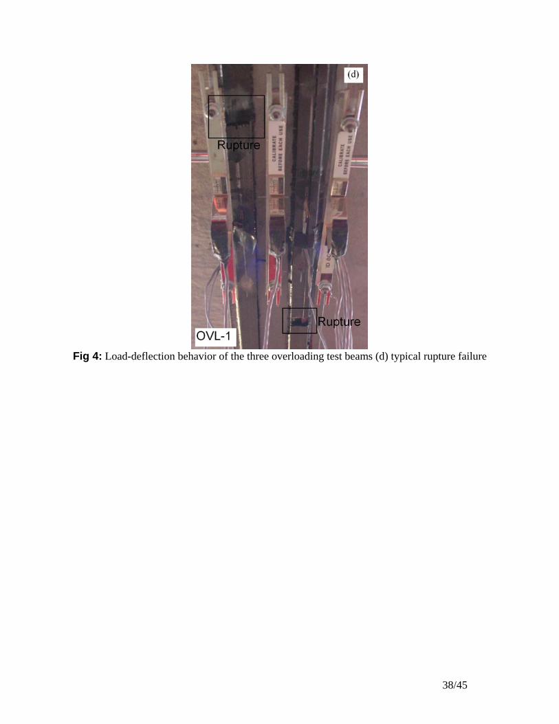
Fig 4: Load-deflection behavior of the three overloading test beams (d) typical rupture failure
38/45

0.85
0.90
0.95
1.00
1.05
0.0 1.0 2.0 3.0 4.0Number of Cycles (millions)
Nor
mal
ized
Stif
fnes
s
FAT-1FAT-1bFAT-CONT
(a) stiffness
0.90
1.00
1.10
1.20
1.30
0.0 1.0 2.0 3.0 4.0
Number of Cycles (millions)
Nor
mal
ized
Def
lect
ion
FAT-1bFAT-1
FAT-CONT
(b) mean deflection Fig 5: Degradation of (a) stiffness and (b) mean deflection for the fatigue beams
39/45

-0.004 -0.002 0 0.002 0.004 Strain (mm/mm)
SHL
OVL-2
0.0025 0.003 0.0035 0.004Strain (mm/mm)
SHL
OVL-2
Fig 6: Strain profiles for beam SHL and OVL-2 (ρ = 8.6%)
40/45

Fig 7: Concrete material properties
Best fit curve
0
10
20
30
40
50
60
70
0 0.001 0.002 0.003 0.004 0.005 0.006 0.007 Strain (mm/mm)
Stre
ss (M
Pa)
( )( )
Cylinder test results nk
cc
cccc
'/1n'/n'ff
εεεε
+−=
Batch 3 (Beam FAT-1b)
Batch 1 (Beam ST-CONT, OVL-1, OVL-2 and SHL)
Batch 2 (Beam FAT-CONT and FAT-1)
41/45

0
50
100
150
200
250
300
350
400
450
0 0.002 0.004 0.006 0.008 0.01Strain (mm/mm)
Stre
ss (M
Pa)
Tension coupon test results
Fig 8: Steel material properties
Tri-linear material model2 εy = 0.0038εp = 0.0016εp = 0.0016 2 y = 0.0038ε
42/45
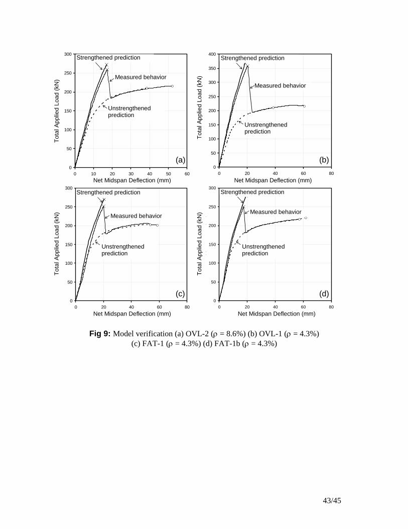
Fig 9: Model verification (a) OVL-2 (ρ = 8.6%) (b) OVL-1 (ρ = 4.3%) (c) FAT-1 (ρ = 4.3%) (d) FAT-1b (ρ = 4.3%)
0
50
100
150
200
250
300
0 10 20 30 40 50 60Net Mid-span Deflection (mm)
Tota
l App
lied
Load
(kN
)
Measured behavior
Unstrengthened prediction
Unstrengthened prediction
0
50
100
150
200
250
300
350
400
0 20 40 60 80Net Mid-s
Strengthened prediction Unstrengthened predictionStrengthened prediction
pan Deflection (mm)
Tota
l App
lied
Load
(kN
)
Measured behavior
Tota
l App
lied
Load
(kN
)
Tota
l App
lied
Load
(kN
)
Measured behaviorMeasured behavior
Unstrengthened prediction
Unstrengthened predictionUnstrengthened prediction
0
50
100
150
200
250
300
0 20 40 60 80Net Mid-span Deflection (mm)
Tota
l App
lied
Load
(kN
)
Unstrengthened prediction
Measured behavior
Unstrengthened prediction
0
50
100
150
200
250
300
0 20 40 60 80
Net Mid-span Deflection (mm)
Tota
l App
lied
Load
(kN
)
Unstrengthened prediction
Measured behavior
Unstrengthened prediction
(a)
(c)
Unstrengthened prediction
Unstrengthened prediction
Strengthened prediction Strengthened prediction
Measured behavior Measured behavior
Net Midspan Deflection (mm)
Net Midspan Deflection (mm) Net Midspan Deflection (mm)
Net Midspan Deflection (mm)
Tota
l App
lied
Load
(kN
)
(d)
(b)
Tota
l App
lied
Load
(kN
)
43/45

0.0
0.5
1.0
1.5
2.0
2.5
3.0
3.5
0.0 10.0 20.0 30.0 40.0 50.0
Reinforcement Ratio of FRP, ρ (%)
Mn,
S / M
n,U
S
Predicted CapacityTest Results
Concrete Crushing
Limit of Effectiveness
FRP Rupture
Fig 10: Effect of reinforcement ratio on nominal moment capacity
44/45

Fig 11: Load levels and moment-curvature behavior for a strengthened beam
Curvature
Mom
ent
Strengthened beam
MD + ML ≤ 0.6 MY,S αD MD + αL ML ≤ MU,S MD + ML ≤ Mn,U
Live Load, ML
Dead Load, MD
Factored Moment,αD MD + αL ML
Strengthened Nominal Capacity, Mn,S
MY,S MY,US
Unstrengthened beam
Strengthened Ultimate Capacity, MU,S
Unstrengthened Nominal Capacity, Mn,U
45/45