
Fatigue Analysis of Welded Structures with ANSYS and · PDF fileFatigue Analysis of Welded...
23
Fatigue Analysis of Welded Structures with ANSYS and FEMFAT ANSYS Conference & 11. CADFEM Austria Users´ Meeting, Linz April 21 st 2016 DI Axel Werkhausen, MAGNA/St. Valentin
Transcript of Fatigue Analysis of Welded Structures with ANSYS and · PDF fileFatigue Analysis of Welded...

© Advanced Engineering / Disclosure or duplication without consent is prohibited
Fatigue Analysis of Welded Structures
with ANSYS and FEMFAT
ANSYS Conference & 11. CADFEM Austria
Users´ Meeting, Linz April 21st 2016
DI Axel Werkhausen, MAGNA/St. Valentin

© Advanced Engineering / Disclosure or duplication without consent is prohibited
Introduction
• ANSYS and ANSYS Workbench are FEM analysis suites – you know maybe better than me – oday it is THEIR Users´Meeting!
• FEMFAT is a fatigue solver – some call it a postprocessor only, but there is a solver inside (for the gradient, for the combination of influences, for the equivalent stress from multi axial loading,…)
• Not only a solver- also for some special purpose a pre- and post processing graphic user interface called FEMFAT visualizer is available.
• By fruitful cooperation there is an up-to-date interface ANSYS-FEMFAT Supporting FEM structure, stresses, nodal temperature, transient stress/strain/temperature, frequency response and transfer function.
• The master-plan is to integrate FEMFAT also in the ANSYS Workbench environment (for standard workflow)
Author: tbd 2 Date: D R A F T

© Advanced Engineering / Disclosure or duplication without consent is prohibited
Interface ANSYS - FEMFAT
Author: tbd Date: D R A F T
*.rst
FEMFAT
*.cdb
Nodes
Elements
PODs
Groups
*.rst, *.lis
*.mcf
Stresses,
temperatures,
*.m
cf
Lo
ad
His
torie
s
Lo
ad
Sp
ectr
a
MB
S
Measure
ment
REPORT
Material Database fatigue data
cyclic hardening
Haigh-Diagrams
S/N-curve…
FEMFAT
visualizer
Damage
Safety Factors
Fatigue Life,…
WELD-Database acc. Guideline
notch factors
Haigh-Diagrams
S/N-curves…
*.fps / *.wdf
Adsasdasahfahfa
ahf afhasfdahf
dfhahfhfafhlökjfgh
saf
qzrqwizrwquitzq
wprp dvv dvddv
dadadaaAdsasdas
ahfahfa ahf
afhasfdahf
dfhahfhfafhlökjfgh
saf
qzrqwizrwquitzq
wprp dvv dvddv
dadadaa
Adsasdasahfahfa
ahf afhasfdahf
dfhahfhfafhlökjfgh
saf
qzrqwizrwquitzq
wprp dvv dvddv
dadadaa
Adsasdasahfahfa
ahf afhasfdahf
dfhahfhfafhlökjfgh
saf
qzrqwizrwquitzq
wprp dvv dvddv
dadadaa
Adsasdasahfahfa
ahf afhasfdahf
dfhahfhfafhlökjfgh
saf
qzrqwizrwquitzq
wprp dvv dvddv
dadadaa

© Advanced Engineering / Disclosure or duplication without consent is prohibited
Motivation
• Weld seam line assessment for approval according to guidelines is manual
exercise and time consuming.
• Weld seam lines in FEM have multiple representation (see next slides)
• The variation in modelling lead to differences in displacements, stress and
fatigue life.
• Most realistic 3D-modelling is too much effort and increases the model size
tremendously. In 1989 this was not an option.
• Shell modelling was common for large steel sheet structures- so a shell
based approach seemed reasonable.
Author: tbd 4 Date: D R A F T
© Advanced Engineering / Disclosure or duplication without consent is prohibited
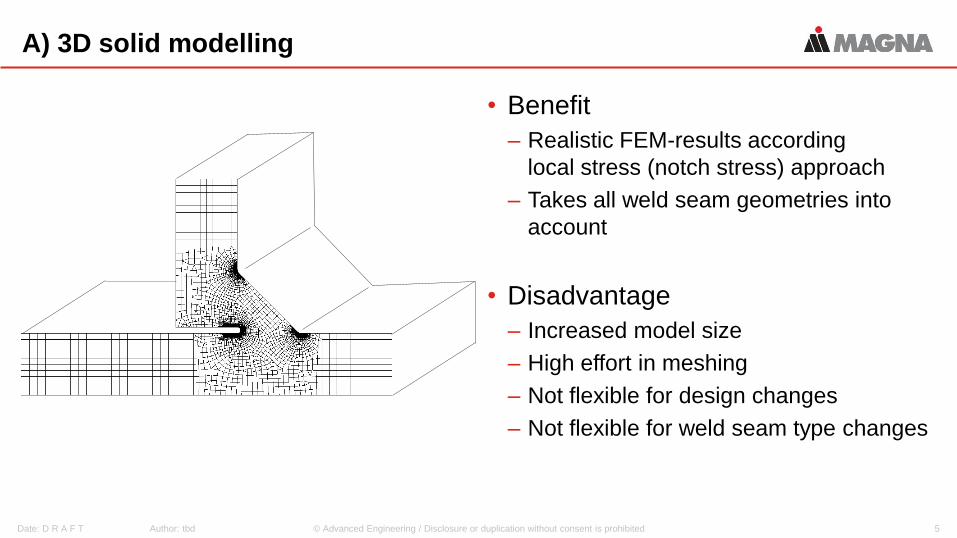
A) 3D solid modelling
• Benefit
– Realistic FEM-results according
local stress (notch stress) approach
– Takes all weld seam geometries into
account
• Disadvantage
– Increased model size
– High effort in meshing
– Not flexible for design changes
– Not flexible for weld seam type changes
Author: tbd 5 Date: D R A F T

© Advanced Engineering / Disclosure or duplication without consent is prohibited
B) Shell model with weld seam inclination
• Benefit
– Simple FE model (meshing)
– Fast modelling
– Takes weld seam size into account
– More flexible to design changes
• Disadvantage
– Non realistic distortion, stress and life
– Not flexible for weld seam type changes
Author: tbd 6 Date: D R A F T

© Advanced Engineering / Disclosure or duplication without consent is prohibited
C) Shell model with extra weld seam element
• Benefit
– Simple FE model (meshing)
– easy modelling
– Takes weld seam size into account
– More flexible to design changes
• Disadvantage
– Needs individual adaption for correct
stiffness
– Not flexible for weld seam type changes
Author: tbd 7 Date: D R A F T

© Advanced Engineering / Disclosure or duplication without consent is prohibited
D) Shell model node-to-node
• Benefit
– Very simple FE model (meshing)
– flexible for weld seam type changes
– easy modelling (mid surface)
– More flexible to design changes
• Disadvantage
– Not taking asymmetric stiffness into
account (bending load)
– No weld seam size taken into account
Author: tbd 8 Date: D R A F T

© Advanced Engineering / Disclosure or duplication without consent is prohibited
Result from investigation
• The optimum to reach should be to
combine the benefits from variant
A) and variant D) to eliminate the
disadvantages.
• FEMFAT weld has taken this
challenge with a compromise to
build up a database for weld seam
parameter
• Since 1989 this database has
grown to a high usability dataset
Author: tbd 9 Date: D R A F T
A B
C D

© Advanced Engineering / Disclosure or duplication without consent is prohibited
Seam weld analysis in FEMFAT
Author: tbd 10 Date: D R A F T
elset MAT205
elset MAT201
elset MAT203
nset C100
nset C102
MAT 203
MAT 205 MAT 201
Color code 100
Color code 102

© Advanced Engineering / Disclosure or duplication without consent is prohibited
Investigate for notchfactors in all loading situation
According to Radaij
and Sonsino we
investigate in 10mm
2-dimensional
submodels for notch
factors.
𝛽𝐿𝐹𝑥=𝜎𝑛𝑜𝑡𝑐ℎ
𝜎𝑛𝑜𝑚𝑖𝑛𝑎𝑙
Author: tbd 11 Date: D R A F T
© Advanced Engineering / Disclosure or duplication without consent is prohibited
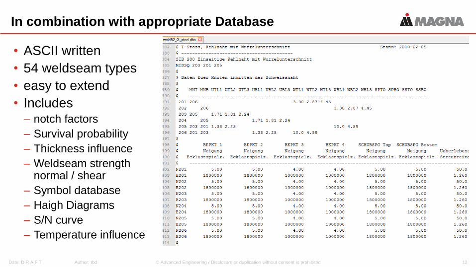
In combination with appropriate Database
• ASCII written
• 54 weldseam types
• easy to extend
• Includes – notch factors
– Survival probability
– Thickness influence
– Weldseam strength normal / shear
– Symbol database
– Haigh Diagrams
– S/N curve
– Temperature influence
Author: tbd 12 Date: D R A F T

© Advanced Engineering / Disclosure or duplication without consent is prohibited
Interface ANSYS - FEMFAT
Author: tbd Date: D R A F T
*.rst *.rst, *.lis
*.mcf
Stresses,
temperatures,
*.m
cf
Lo
ad
His
torie
s
Lo
ad
Sp
ectr
a
MB
S
Measure
ment
REPORT
Material Database fatigue data
cyclic hardening
Haigh-Diagrams
S/N-curve…
FEMFAT
visualizer
Damage
Safety Factors
Fatigue Life,…
WELD-Database acc. Guideline
notch factors
Haigh-Diagrams
S/N-curves…
*.fps / *.wdf
Adsasdasahfahfa
ahf afhasfdahf
dfhahfhfafhlökjfgh
saf
qzrqwizrwquitzq
wprp dvv dvddv
dadadaaAdsasdas
ahfahfa ahf
afhasfdahf
dfhahfhfafhlökjfgh
saf
qzrqwizrwquitzq
wprp dvv dvddv
dadadaa
Adsasdasahfahfa
ahf afhasfdahf
dfhahfhfafhlökjfgh
saf
qzrqwizrwquitzq
wprp dvv dvddv
dadadaa
Adsasdasahfahfa
ahf afhasfdahf
dfhahfhfafhlökjfgh
saf
qzrqwizrwquitzq
wprp dvv dvddv
dadadaa
Adsasdasahfahfa
ahf afhasfdahf
dfhahfhfafhlökjfgh
saf
qzrqwizrwquitzq
wprp dvv dvddv
dadadaa
*.cdb
Nodes
Elements
PODs
Groups
FEMFAT

© Advanced Engineering / Disclosure or duplication without consent is prohibited
Data export from ANSYS
• FE geometry from *.cdb-file including set definition
To obtain this file from Workbench execute the comman
CDWRITE, DB, W:\pathname\femfat_ansys, cdb
• FEM stress result from each loadcase in *.rst-file
seek in project export directory workdir
projectname
dp0
SYS
MECH/file.rst
Author: tbd 14 Date: D R A F T

© Advanced Engineering / Disclosure or duplication without consent is prohibited
Import *.cdb-file
Author: tbd 15 Date: D R A F T

© Advanced Engineering / Disclosure or duplication without consent is prohibited
Import stress file
Author: tbd 16 Date: D R A F T
Maximum load is defined as „upper stress“.
Leave lower stress at „0“ for pulsating load.

© Advanced Engineering / Disclosure or duplication without consent is prohibited
Loading applied: 1 kN
Author: tbd 17 Date: D R A F T
The Tasks:
a) how many cycles
does the component
withstand until crack
initiates?
b) Where does the
crack start?
c) Which location in
weld seam?

© Advanced Engineering / Disclosure or duplication without consent is prohibited
FEMFAT Analysis settings
• Material: higher strength weldable steel EN-S355
• Loadspectra: 1.000 cycles
• Surface roughness: 10μm
• Mean stress influence: ON (pulsating has mean stress same as amplitude)
• Damage Analysis: Miner modified
• Equivalent stress: scaled normal stress
• Analysis filter: amplitude stress > 40% of fatigue limit (default)
• FEMFAT weld database: ECS standard (Radaiji / Sonsino, DIN 15018)
Author: tbd 18 Date: D R A F T

© Advanced Engineering / Disclosure or duplication without consent is prohibited
Answer a) Damage = 1/Fatigue life
Author: tbd 19 Date: D R A F T
a) Life:
483.4x 1.000 cycles
483.400 cycles

© Advanced Engineering / Disclosure or duplication without consent is prohibited
Answer b) Location of crack initiation
• in weld seam (Attribute 100)
• web-element (Type 206, E5652)
• Root crack (NWUTOP =
Naht
Wurzel
TOP-shell side
Author: tbd 20 Date: D R A F T
Answer c)
Seam line direction (From, To)

© Advanced Engineering / Disclosure or duplication without consent is prohibited
Weld seam definition in FEMFAT visualizer
• Life demo of weld seam definition in neutralized FE-geometry
• Same results but additional information available from small pictogram
Author: tbd 21 Date: D R A F T

© Advanced Engineering / Disclosure or duplication without consent is prohibited
Optional: sensitivity analysis
• See presentation for CADFEM usermeeting in 2014
Author: tbd 22 Date: D R A F T

© Advanced Engineering / Disclosure or duplication without consent is prohibited Author: tbd 23 Date: D R A F T
Thank you for your kind attention !


