( Analysis Of Welded Joint Strength Using ANSYS )kti.mtu.edu.iq/researches/project303637691.pdf ·...
22
1 The name of god Republic Of Iraq Ministry Of Higher Education and Scientific Research University Technical of central Mechanical Technical / production ( Analysis Of Welded Joint Strength Using ANSYS ) A graduation project is submitted to the Mechanical Department in partial fulfillment of the requirements for the degree of Diploma of Science in Mechanical Technical / production BY 1 Ra'ed Hmoud Hadi 2 Saif Sa'ad Mohammed 3 Ayaat Mohammed Marbat SUPERVISOR Eng. Ghassan Shaker Abdul-Ridha Al-kut, Iraq Date 2018
Transcript of ( Analysis Of Welded Joint Strength Using ANSYS )kti.mtu.edu.iq/researches/project303637691.pdf ·...
1
The name of god
Republic Of Iraq
Ministry Of Higher Education and Scientific
Research
University Technical of central
Mechanical Technical / production
( Analysis Of Welded Joint Strength Using ANSYS )
A graduation project is submitted to the Mechanical Department in partial
fulfillment of the requirements for the degree of Diploma of Science in
Mechanical Technical / production
BY
1 Ra'ed Hmoud Hadi
2 Saif Sa'ad Mohammed
3 Ayaat Mohammed Marbat
SUPERVISOR
Eng. Ghassan Shaker Abdul-Ridha
Al-kut, Iraq
Date
2018

2
تعالى هللا قال
بسم هللا الرحمن الرحيم
( خلق اإلنسان من 1اقرأ باسم رب ك الذي خلق )( الذي علم بالق لم 3( اقرأ وربك األكرم )2علق )
( 5( علم اإلنسان ما لم يعلم )4)
)صدق هللا العلي العظيم(
)سورة العلق(
3
اإلهداء
الى من يسعد ق لبي بلقياهااالزهارالى روضة الحب التي تنبت أزكى
أمي
لى رمز الرجولة والتضحيةإ من دفعني الى العلم وبه ازداد افتخار لىإ
ابي
الى من هم اقرب الي من روحي الى من شاركني حضن االم وبهم استمد عزتي واصراري
اخوتي
ا وتقديرا نسني في دراستي وشاركني همومي تذكارآالى من اصدق ائي
الفتي والجبارالى هذا الصرح العلمي
لتقنيالمعهد ا

4
وتقديــر شكــر
محمد نبينا والمرسلين الخلق أشرف على والسالم والصالة العالمين، رب هلل الحمد
الطاهرين الطيبين آله وعلى وسلم عليه هللا صلى .
الذي وتعالى، سبحانه( هللا) وجل عز الباري المنعم إلى به أتقدم وآخره الشكر أول
شق في والقوة الصبر وألهمني عسير، كل لي ويسر العظيمة، اإللهية برعايته أحاطني
العلمي البحث نحو طريقي .
/ األستاذ القدير الفاضل أستاذي إلى امتناني وعظيم وتقديري شكري بخالص وأتوجه
وما مخلصة، علمية وروح صدر ورحابة رعاية حسن من أبداه لما ؛ الكناني شاكر غسان
بالخير له فدعائي... ومستمرة قيمة ومالحظات سديدة ونصائح توجيهات من لي قدمه
.والعافية
5
Contents page
❖ ABSTRAC ………………… 8
❖ 1. INTRODUCTION ……… 10
1.1 DEFINITION TENSILE TEST …………. 11
1.2 PARAMETERS FRICTION STIR WELDING ……..... 12
1.3 SKETCH OF 2D MODE ………… 13
❖ 2. ANLYSIS OF TENSILE TEST (NON-WELD) ………. 14
2.2 MESHING …………. 15
2.2 MARERIAL PROPERTIES …………….. 16
2.3 EXPLICIT DYNAMICS (LOADS & SUPPORTS) …. 17
❖ 3. ANLYSIS OF TENSILE TEST (WELD) ……………… 18
3.1 SIMULATION OF FRICTION STIR WELDING ……. 18
3.2 MODEL & MESHING ………………….. 19
3.3 EXPLICIT DYNAMICS (LOADS & SUPPORTS) ……. 20
❖ 4. ALL ANALYSIS RESULTS …………………. 21
❖ 5. CONCLUSION …………………….………….. 23
❖ 6. REFRENCES ………………………..………… 25

6
LIST OF FIGURES
✓ Fig.1: schematic illustration of FSW process
✓ Fig.2 Schematic diagram of tool
✓ Fig.3 Model FSW Tool
✓ Fig.4. Tow Dimension of the specimen A) Non-weld B) Weld
✓ Fig.5 Model of Tensile Test specimen
✓ Fig.5 Model of Tensile Test (Non-Weld specimen)
✓ Fig.6 EXPLICIT DYNAMICS (LOADS & SUPPORTS) (Non-Weld specimen)
✓ Fig.7 Model of FSW AA6016-T6 in Mechanical APDL
✓ Fig.8 Face split & Cutting Material
✓ Fig.9 The Model of A welded specimen (Ready for Testing)
✓ Fig.10 Model of Tensile Test (Weld Specimen)
✓ Fig.11 Equivalent Stress A) Weld Specimen B) Non-Weld Specimen
✓ Fig.12 Deformation A) Weld Specimen B) Non-Weld Specimen
✓ Fig.13 Temperatureall A) Weld Specimen B) Non-Weld Specimen
LIST OF TABLES
Table 1 : Mechanical properties of FSW Tool material
Table 2 : Mechanical properties of working materials
Table 3 : Parameters of FSW
Table 4: Comparison results between Weld & Non Weld Specimen

7
Abstract :
The simulation of the welder was compared to the specimen of the tensile test with another specimen without welding, and both specimens Prepared as per ASTM for the Aluminum alloy (AA6061-T6). Where it was analysis 0f welded joint strength by calculating the stresses and strain and deformation for both specimens in ANSYS workbench.

8
1. INTRODUCTION
Friction stir welding (FSW) is a recently emerged solid-state joining technology patented by The welding Institute (TWI) in 1991. Friction stir welding (FSW) is a solid state joining process that uses friction generated by a rotating cylindrical tool which produces heat and plasticize metal on either side of a joint, creating a solid functional weld. Friction- generated heat is more effective at reorganizing the microstructure of metals and metal alloys than other forms of fusion welding. This joining technique is energy efficient, environment friendly, and versatile. In particular, it can be used to join high-strength aerospace Aluminum alloys and other metallic alloys that are hard to weld by conventional fusion welding. FSW is considered to be the most significant development in metal

9
:1.1 Definition of tensile test
Tensile testing also known as tension testing is a fundamental materials science and engineering test a sample is subjected To controlled tension until failure properties in which that are directly measured via a tensile test are ultimate tensile strength breaking strength , maximum elongation and reduction in area. From these measurements the following properties can also be determine: Young’s modulus, poisson’s ratio , yield strength , and strain hardening characteristics . Uniaxial tensile testing is the most commonly used obtaining the mechanical characteristics Of isotropic materials .
10
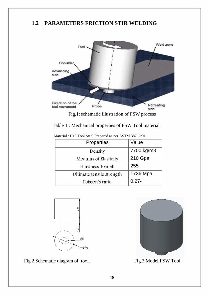
1.2 PARAMETERS FRICTION STIR WELDING
Fig.1: schematic illustration of FSW process
Table 1 : Mechanical properties of FSW Tool material
Material : H13 Tool Steel Prepared as per ASTM 387 Gr91
Fig.2 Schematic diagram of tool. Fig.3 Model FSW Tool
Properties Value
Density 7700 kg/m3
Modulus of Elasticity 210 Gpa
Hardness, Brinell 255
Ultimate tensile strength 1736 Mpa
Poisson’s ratio 0.27-

11
1.3 SKETCH OF 2D MODEL
In fig.4 we see the Dimension of the 2D of the tensile test specimen
Fig.4.A Tow Dimension of the specimen (Non-weld) (mm)
Fig.4.B Tow Dimension of the specimen (Weld) (mm)

12
2. ANLYSIS OF TENSILE TEST (NON-WELD)
For tensile test in ANSYS, Should go with explicit dynamics analysis. Because
tensile test in a non-linear case and using explicit dynamics will give the best
results.
Fig.5 Model of Tensile Test specimen
13
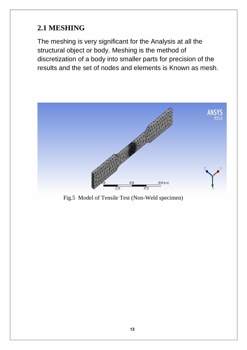
2.1 MESHING
The meshing is very significant for the Analysis at all the
structural object or body. Meshing is the method of
discretization of a body into smaller parts for precision of the
results and the set of nodes and elements is Known as mesh.
Fig.5 Model of Tensile Test (Non-Weld specimen)

14
2.2 MARERIAL PROPERTIES
Table 2 : Mechanical properties of working materials
Properties Value
Density 2.70 g/cc
Tensile Strength,
Yield
193 MPa
Modulus of
Elasticity
68.9 GPa
Poissons Ratio 0.33
Shear Modulus 26.0 GPa
Specific Heat
Capacity
0.895 J/g°C
Thermal
Conductivity
218 W/mK

15
2.3 EXPLICIT DYNAMICS (LOADS & SUPPORTS)
Tensile Test was performed on specimen in ANSYS Workbench out by
fixing the specimen from one side by (Fixed Support) and Tensile it from
the other side by (Displacement)
Fig.6 EXPLICIT DYNAMICS (LOADS & SUPPORTS) (Non-Weld specimen)

16
3. ANLYSIS OF TENSILE TEST (WELD)
3.1 SIMULATION OF FRICTION STIR WELDING
Fig.7 Model of FSW AA6016-T6 in Mechanical APDL
Table 3 : Parameters of FSW
Rotational velocity 1200 R.P.M
Feed 40 mm/Min
Time =distance/speed 200/40 = 5 Min
Load 70 N

17
3.2 MODEL & MESHING
Cut Material in ANSYS
Fig.8 Face split & Cutting Material
Fig.9 The Model of A welded specimen (Ready for Testing)

18
3.3 EXPLICIT DYNAMICS (LOADS & SUPPORTS)
[A] Fixed Support
[B] Displacement
Fig.10 Model of Tensile Test (Weld Specimen)
19
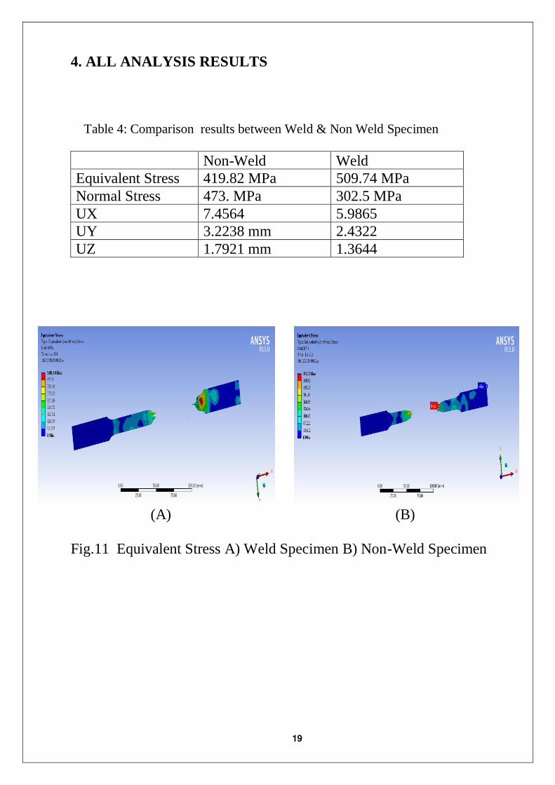
4. ALL ANALYSIS RESULTS
Table 4: Comparison results between Weld & Non Weld Specimen
Non-Weld Weld
Equivalent Stress 419.82 MPa 509.74 MPa
Normal Stress 473. MPa 302.5 MPa
UX 7.4564 5.9865
UY 3.2238 mm 2.4322
UZ 1.7921 mm 1.3644
(A) (B)
Fig.11 Equivalent Stress A) Weld Specimen B) Non-Weld Specimen

20
(A) (B)
Fig.12 Deformation A) Weld Specimen B) Non-Weld Specimen
(A) (B)
Fig.13 Temperatureall A) Weld Specimen B) Non-Weld Specimen
21
5. CONCLUSION
It was observed that the mechanical properties such as tensile strength
and hardness were getting better in the Friction Stir welded and
produce low welding distortion. Thus Friction stir welding technology
has the potential to play an important role in the near future for
improving the quality of the engineering components

22
6. REFRENCE
[1] Cavaliere P, Nobile R, Panella.F (2005) “Mechanical And Microstructural
Behaviour Of 2024–7075 Aluminum Alloy Sheets Joined By Friction Stir
Welding” International Journal Of Machine Tools & Manufacture 46 (2006)
588–594
[2] Elangovan K, Balasubramanian. V (2008) ”Influences Of Tool Pin Profile
And Tool Shoulder Diameter On The Formation Of Friction Stir Processing
Zone In AA6061 Aluminum Alloy” Materials And Design 29 (2008) 362–373
[3] Liechty B.C, Webb B.W (2008)”Modeling The Frictional Boundary
Condition In Friction Stir Welding” International Journal Of Machine Tools &
Manufacture 48 (2008) 1474– 1485
[4] Silva A, Arruti E, Janeiro ,G(2011) “Material Flow And Mechanical
Behavior Of Dissimilar AA2024-T3 Andaa7075-T6 Aluminum Alloys Friction
Stir Welds” Materials And Design 32 (2011) 2021–2027.