Fast Mask Image Projection-Based Micro-Stereolithography ... · According to the experimental...
6
Fast Mask Image Projection-Based Micro-Stereolithography Process for Complex Geometry Yayue Pan 1 Mem. ASME Department of Mechanical and Industrial Engineering, University of Illinois at Chicago, 842 W. Taylor Street, ERF 2039, Chicago, IL 60607 e-mail: [email protected] Yong Chen Mem. ASME Epstein Department of Industrial and Systems Engineering, University of Southern California, 3715 McClintock Avenue, GER 201, Los Angeles, CA 90089 e-mail: [email protected] Zuyao Yu School of Ship and Ocean Engineering, Huazhong University of Science and Technology, 1037 Luoyu Road, East Building 2-118, Wuhan 430074, Hubei e-mail: [email protected] In micro-stereolithograhy (lSL), high-speed fabrication is a criti- cal challenge due to the long delay time for refreshing resin and retaining printed microfeatures. Thus, the mask-image-projection- based micro-stereolithograhy (MIP-lSL) using the constrained surface technique is investigated in this paper for quickly recoat- ing liquid resin. It was reported in the literature that severe dam- ages frequently happen in the part separation process in the constrained-surface-based MIP-lSL system. To conquer this problem, a single-layer movement separation approach was adopted, and the minimum delay time for refreshing resin was experimentally characterized. The experimental results verify that, compared with the existing MIP-lSL processes, the MIP-lSL process with single-layer movement separation method developed in this paper can build microstructures with complex geometry, with a faster build speed. [DOI: 10.1115/1.4035388] 1 Introduction The MIP-lSL technology is an additive manufacturing (AM) approach for fabricating microstructures with three-dimensional (3D) complex geometry, especially with high aspect ratios [1–5]. Compared with other micro-manufacturing technologies such as lithography gavolnoforming abforming (LIGA) and micromachin- ing [6,7], MIP-lSL technology has the merits of simpler process- ing, faster fabrication speed, lower machine cost, and better capability of fabricating complex geometry. Various applications of MIP-lSL have been investigated, including the fabrication of microfluidic devices, scaffolds of biocompatible polymers for tis- sue reconstruction, microrobotics, etc. [8–11]. To fabricate a micropart using MIP-lSL, first, a 3D computer-aided design (CAD) model is sliced to generate a set of two-dimensional (2D) layers. Each sliced layer is saved as a digital mask image, which is then projected usually by a digital micromirror device (DMD) to cure a thin layer of liquid resin [10–15]. The smallest feature reported by the MIP-lSL process is 0.6 lm[11]. Most MIP-lSL systems use a top–down projection approach. Related MIP-lSL systems based on the top–down projection approach are illustrated in Fig. 1(a). A good property of the top–down projection approach is that top surface of the cured layers is free, making it always fea- sible to recoat a new layer of liquid resin on top of the cured layer. However, when the needed new layer of liquid resin becomes thin, the recoating process becomes more challenging and some- times even impossible, because of the liquid viscosity and surface tension. A resin recoating process based on a sweeper is usually required to flatten the top surface. For low-viscosity resins, a deep-dip recoating approach with a long waiting time can also be used to replace the surface sweeping process. In comparison, a schematic diagram of the MIP-lSL systems based on bottom–up projection is shown in Fig. 1(b). Although the bottom–up projection-based MIP-lSL systems have now been widely used to fabricate macroscale structures, a relatively less lit- erature [10] was reported to fabricate microstructures using such a constrained-surface-based approach. As a cured layer is con- strained by the tank surface, it is found that the separation of the cured part is a critical issue, especially when it has microfeatures. The fabricated microstructure can be broken easily during the layer separation process. Hence, the adoption of such bottom–up projection approach in microstructure fabrication is greatly lim- ited due to the layer separation. In this paper, we discuss how to achieve fast build speed in the MIP-lSL process based on the bottom–up projection method. We tried to minimize the resin refreshing time by utilizing the bottom–up projection configuration and a single-layer movement separation approach. A testbed was developed and experiments were performed for various geometries to validate the developed MIP-lSL approaches. 2 A Fast MIP-lSL Process Design 2.1 Fast MIP-lSL Process Based on Bottom–Up Projection. It is found that a large separation force may occur and bubbles will be generated during the separation process, espe- cially when a small layer thickness and a fast separating speed are used. Therefore, a 2-mm thick flexible layer of polydimethylsilox- ane (PDMS, Sylgard 184 from Dow Corning, Midland, MI) is coated on the bottom surface of the liquid vat to assist the separa- tion [16,17]. After projecting a mask image through the bottom surface of the liquid vat for a certain time and curing a layer of resin, the platform is moved up with a proper velocity along the Z Fig. 1 Schematic of MIP-lSL systems based on the top–down projection method (a) and the bottom–up projection method (b) 1 Corresponding author. Contributed by the Manufacturing Engineering Division of ASME for publication in the JOURNAL OF MICRO- AND NANO-MANUFACTURING. Manuscript received April 19, 2016; final manuscript received November 30, 2016; published online January 6, 2017. Assoc. Editor: Cheryl Xu. Journal of Micro- and Nano-Manufacturing MARCH 2017, Vol. 5 / 014501-1 Copyright V C 2017 by ASME Downloaded From: http://micronanomanufacturing.asmedigitalcollection.asme.org/pdfaccess.ashx?url=/data/journals/ajmnbt/935870/ on 02/03/2017 Terms of Use: http://www.a
Transcript of Fast Mask Image Projection-Based Micro-Stereolithography ... · According to the experimental...

Fast Mask Image Projection-Based
Micro-Stereolithography Process
for Complex Geometry
Yayue Pan1
Mem. ASME
Department of Mechanical and Industrial Engineering,
University of Illinois at Chicago,
842 W. Taylor Street,
ERF 2039,
Chicago, IL 60607
e-mail: [email protected]
Yong ChenMem. ASME
Epstein Department of Industrial and Systems Engineering,
University of Southern California,
3715 McClintock Avenue,
GER 201,
Los Angeles, CA 90089
e-mail: [email protected]
Zuyao YuSchool of Ship and Ocean Engineering,
Huazhong University of Science and Technology,
1037 Luoyu Road,
East Building 2-118,
Wuhan 430074, Hubei
e-mail: [email protected]
In micro-stereolithograhy (lSL), high-speed fabrication is a criti-cal challenge due to the long delay time for refreshing resin andretaining printed microfeatures. Thus, the mask-image-projection-based micro-stereolithograhy (MIP-lSL) using the constrainedsurface technique is investigated in this paper for quickly recoat-ing liquid resin. It was reported in the literature that severe dam-ages frequently happen in the part separation process in theconstrained-surface-based MIP-lSL system. To conquer thisproblem, a single-layer movement separation approach wasadopted, and the minimum delay time for refreshing resin wasexperimentally characterized. The experimental results verifythat, compared with the existing MIP-lSL processes, theMIP-lSL process with single-layer movement separation methoddeveloped in this paper can build microstructures with complexgeometry, with a faster build speed. [DOI: 10.1115/1.4035388]
1 Introduction
The MIP-lSL technology is an additive manufacturing (AM)approach for fabricating microstructures with three-dimensional(3D) complex geometry, especially with high aspect ratios [1–5].Compared with other micro-manufacturing technologies such aslithography gavolnoforming abforming (LIGA) and micromachin-ing [6,7], MIP-lSL technology has the merits of simpler process-ing, faster fabrication speed, lower machine cost, and bettercapability of fabricating complex geometry. Various applicationsof MIP-lSL have been investigated, including the fabrication of
microfluidic devices, scaffolds of biocompatible polymers for tis-sue reconstruction, microrobotics, etc. [8–11]. To fabricate amicropart using MIP-lSL, first, a 3D computer-aided design(CAD) model is sliced to generate a set of two-dimensional (2D)layers. Each sliced layer is saved as a digital mask image, whichis then projected usually by a digital micromirror device (DMD)to cure a thin layer of liquid resin [10–15]. The smallest featurereported by the MIP-lSL process is 0.6 lm [11]. Most MIP-lSLsystems use a top–down projection approach. Related MIP-lSLsystems based on the top–down projection approach are illustratedin Fig. 1(a). A good property of the top–down projection approachis that top surface of the cured layers is free, making it always fea-sible to recoat a new layer of liquid resin on top of the cured layer.However, when the needed new layer of liquid resin becomesthin, the recoating process becomes more challenging and some-times even impossible, because of the liquid viscosity and surfacetension. A resin recoating process based on a sweeper is usuallyrequired to flatten the top surface. For low-viscosity resins, adeep-dip recoating approach with a long waiting time can also beused to replace the surface sweeping process.
In comparison, a schematic diagram of the MIP-lSL systemsbased on bottom–up projection is shown in Fig. 1(b). Althoughthe bottom–up projection-based MIP-lSL systems have now beenwidely used to fabricate macroscale structures, a relatively less lit-erature [10] was reported to fabricate microstructures using such aconstrained-surface-based approach. As a cured layer is con-strained by the tank surface, it is found that the separation of thecured part is a critical issue, especially when it has microfeatures.The fabricated microstructure can be broken easily during thelayer separation process. Hence, the adoption of such bottom–upprojection approach in microstructure fabrication is greatly lim-ited due to the layer separation.
In this paper, we discuss how to achieve fast build speed in theMIP-lSL process based on the bottom–up projection method. Wetried to minimize the resin refreshing time by utilizing thebottom–up projection configuration and a single-layer movementseparation approach. A testbed was developed and experimentswere performed for various geometries to validate the developedMIP-lSL approaches.
2 A Fast MIP-lSL Process Design
2.1 Fast MIP-lSL Process Based on Bottom–UpProjection. It is found that a large separation force may occurand bubbles will be generated during the separation process, espe-cially when a small layer thickness and a fast separating speed areused. Therefore, a 2-mm thick flexible layer of polydimethylsilox-ane (PDMS, Sylgard 184 from Dow Corning, Midland, MI) iscoated on the bottom surface of the liquid vat to assist the separa-tion [16,17]. After projecting a mask image through the bottomsurface of the liquid vat for a certain time and curing a layer ofresin, the platform is moved up with a proper velocity along the Z
Fig. 1 Schematic of MIP-lSL systems based on the top–downprojection method (a) and the bottom–up projection method (b)
1Corresponding author.Contributed by the Manufacturing Engineering Division of ASME for publication
in the JOURNAL OF MICRO- AND NANO-MANUFACTURING. Manuscript received April 19,2016; final manuscript received November 30, 2016; published online January 6,2017. Assoc. Editor: Cheryl Xu.
Journal of Micro- and Nano-Manufacturing MARCH 2017, Vol. 5 / 014501-1Copyright VC 2017 by ASME
Downloaded From: http://micronanomanufacturing.asmedigitalcollection.asme.org/pdfaccess.ashx?url=/data/journals/ajmnbt/935870/ on 02/03/2017 Terms of Use: http://www.asme.org/about-asme/terms-of-use

direction by a certain distance. Enough waiting time is necessaryto ensure the complete filling of liquid resin in the gap with nobubbles existing. Since for a given setup with a preselected liquidresin, process parameters such as layer thickness, light intensity,and resin curing time can be determined for the MIP-SL process;a significant portion of the MIP-lSL fabrication time that can beadjusted through process control is the resin recoating time.Therefore, to achieve a fast building process, the process parame-ters that determine resin recoating are critical, which are investi-gated in the paper including the moving-up distance and the delaytime for complete filling of liquid resin. They are further mini-mized through experimental study for a fast MIP-lSL process.
2.2 Experimental Study of Parameters Settings. Inbottom–up projection-based MIP-lSL process, fresh liquid maynot be able to fill the gap completely in time, and bubbles may begenerated in the liquid-filling process if the separation speed is toohigh. A long waiting time and a big moving distance would guar-antee a complete filling of liquid resin in the gap; however, thebuilding time will be longer. Hence, it is desired to identify theshortest waiting time and smallest moving distance in order toachieve a fast fabrication speed. To identify the minimum waitingtime needed to guarantee a complete filling of liquid resin, a pro-totype has been developed, as discussed in Sec. 3, and the experi-ments have been performed based on it.
Cubes with various sizes are built by using different waitingtimes and moving distances for a commercial resin (SI500 fromEnvisionTec) with a viscosity of 200 cP. For example, Fig. 2shows a cube model of 6.96� 6.96� 2 mm3. If the built partshave holes or deep shadows under a microscope, the waiting timeis considered insufficient. Accordingly, a longer waiting time willbe used to rebuild the parts. A critical waiting time for void-freecuring is identified for different gap sizes.
Figure 3 plots the relation between the critical waiting time, thecube size, and the Z movement distance. In all the tests, the sameZ movement speed (0.05 mm/s) was used to lift the platform up. Itcan be observed that:
(1) The minimum waiting time increases with the dimensionalsize for the same gap height, and bigger gap height resultsin a smaller minimum waiting time.
(2) When the cross section size of the cured layer is smallerthan 6 mm, and the gap size is bigger than 10 lm, no wait-ing time is needed to get the gap completely filled by thetested liquid resin. However, when the solid cross sectionsize of the cured layer is bigger than 6 mm, a minimumwaiting time tw is required in order to achieve nonvoid andbubble-free liquid resin filling. For the given setup, tw canbe determined by using the following fitted experimentalmodel:
tw ¼0 x � 6:01 mm
2:99h2 � 14:07hþ 16:46
2:64h2 � 14:56hþ 20:96
6:01 mm < x � 6:45 mm
6:45 mm < x � 6:99 mm
8<:
(1)
where h is the gap height (�10�5 m), and x is the solid cross sec-tion size of the layer.
2.3 Build Time of a Layer With the Single-LayerMovement Approach. According to the calibration tests for thepreselected liquid resin, a single-layer separation and resin recoat-ing process is developed by setting one-layer-thickness gap heightand the minimum waiting time based on Eq. (1). Figure 4 presents
Fig. 2 Test results for identifying the minimum gap size and waiting time: (a) CAD model; (b) built part with insufficient wait-ing time; (c) void-free parts; (d) surface with a hole; (e) shadows due to incomplete filling; and (f) void-free surface
Fig. 3 The flow-filling time with different Z movement distance
014501-2 / Vol. 5, MARCH 2017 Transactions of the ASME
Downloaded From: http://micronanomanufacturing.asmedigitalcollection.asme.org/pdfaccess.ashx?url=/data/journals/ajmnbt/935870/ on 02/03/2017 Terms of Use: http://www.asme.org/about-asme/terms-of-use
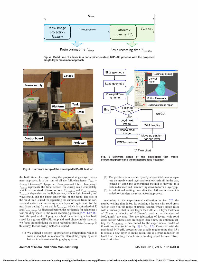
the build time of a layer using the proposed single-layer move-ment approach. It is the sum of all the following items: Tlayer¼Tcuringþ Trecoating¼ (Tprojectionþ Twait_projection)þ (Tzþ Twait_filling).Tcuring represents the time needed for curing resin completely,which is comprised of two portions, Tprojection and Twait_projection.Tcuring is dependent on the light source, such as light intensity andwavelength, and the photo-sensitivities of the resin. The rest ofthe build time is used for separating the cured layer from the con-strained surface and recoating a new layer of liquid resin for thenext-layer curing. So we call it Trecoating, which is comprised of Tz
and Twait_filling. As discussed before, the bottleneck for achieving afast building speed is the resin recoating process [8,9,11,17,18].With the goal of developing a method for achieving a fast buildspeed for a given MIP-lSL setup and used photocurable material,we focus on minimizing the resin recoating time, i.e., Trecoating. Inthis study, the following methods are used:
(1) We utilized a bottom–up projection configuration, which iswidely adopted in macroscale stereolithography systemsbut not in micro-stereolithography systems.
(2) The platform is moved up by only a layer thickness to sepa-rate the newly cured layer and to allow resin fill in the gap,instead of using the conventional method of moving up acertain distance and then moving down to form a layer gap.
(3) An additional waiting time after the platform movement isadded to complete the resin recoating process.
According to the experimental calibration in Sec. 2.2, theneeded waiting time is 0 s, for printing a feature with solid crosssection size x in the range of (0 mm, 6 mm), when a liquid resinwith a viscosity, that is, not larger than 200 cP, a layer thicknessof 20 lm, a velocity of 0.05 mm/s, and an acceleration of0.005 mm/s2 are used. For the fabrication of layers with solidcross section whose sizes are bigger than 6 mm, the optimum set-ting for Twait_filling is determined by the experimental model offlow-filling time (refer to Eq. (1) in Sec. 2.2). Compared with thetraditional MIP-lSL processes that usually require more than 15 sto recoat a new layer of liquid resin, this is a great reduction ofbuild time, enabling a much faster building speed for microstruc-ture fabrication.
Fig. 4 Build time of a layer in a constrained-surface MIP-lSL process with the proposedsingle-layer movement approach
Fig. 5 Hardware setup of the developed MIP-lSL testbed
Fig. 6 Software setup of the developed fast micro-stereolithography and the related process flowchart
Journal of Micro- and Nano-Manufacturing MARCH 2017, Vol. 5 / 014501-3
Downloaded From: http://micronanomanufacturing.asmedigitalcollection.asme.org/pdfaccess.ashx?url=/data/journals/ajmnbt/935870/ on 02/03/2017 Terms of Use: http://www.asme.org/about-asme/terms-of-use

3 Experimental Setup
As shown in Fig. 5, in order to verify the proposed micro-manufacturing approach, a hardware setup and a software havebeen built. A DMD-based projection device was developed bymodifying a commercial projector from Acer. In particular, opti-cal system settings, such as the projection image focus, light con-trast, and light intensity, have been adjusted or modified to projecta well-focused image on the liquid resin curing plane. A blue filterand a black mask are used to filter the light. A clear glass Petridish coated with PDMS on the bottom is used as the resin tank.The envelope size is 9.32 mm (X)� 6.99 mm (Y)� 50 mm (Z).The projection image resolution of the prototype system is 9 lm.Note that by selecting different optics, e.g., light sources andlenses, larger or smaller build envelope size with different levelsof resolution can be achieved in the MIP-lSL process. In addition,a process control software has been developed using Visual Cþþ.It integrates the slicing, image loading, projection, and motioncontrolling, as shown in Fig. 6.
4 Experimental Results and Discussion
4.1 Test Cases. To calibrate the micro-manufacturing capa-bility of the developed process, cylinders with varied diameters,and channels with varied sizes have been printed and character-ized by measuring the fabricated microstructures using a precisionmeasurement equipment from Micro-Vu (Windsor, CA) and com-paring with the CAD model. It was found that the smallest pillarand the smallest gap that the system can build are 50 lm and110 lm, respectively. The tolerance of the solid cylinders isaround 6 4 lm, and the tolerance of the channel isaround 6 10 lm. A contour elite 3D optical microscope fromBruker (Billerica, MA) was used to measure the surface rough-ness. The top surface of the printed cube in Fig. 2(d) has an aver-age roughness (Ra) value of 0.1 lm. Other postprocess techniquessuch as chemical etching, post-curing, and meniscus approach canimprove the precision and surface finish of fabricated objects.
To verify the capability of the system on building complexmicrostructures or mesoscale parts with microfeatures based onthe fast printing method, various tests have been carried out fordifferent geometries. CAD models, built parts, and the relatedmicroscopic images are shown in Figs. 7–10. In all the tests,Twait_filling is determined by Eq. (1) in Sec. 2.2. If the calculated
Fig. 7 A microgear: (a) CAD model; (b) built part; and (c) microscopic image
Fig. 9 A hearing-aid: (a) CAD model with added supports; (b)built physical object; and (c) microscopic image of the built part(top view)
Fig. 8 A turbofan: (a) CAD model and (b) microscopic image ofthe built part
Fig. 10 A threaded pipe: (a) CAD model of the pipe and (b)–(e)built physical object
014501-4 / Vol. 5, MARCH 2017 Transactions of the ASME
Downloaded From: http://micronanomanufacturing.asmedigitalcollection.asme.org/pdfaccess.ashx?url=/data/journals/ajmnbt/935870/ on 02/03/2017 Terms of Use: http://www.asme.org/about-asme/terms-of-use
waiting time is 0, a 0.1 s Twait_filling is used to compensate anypotential noises. A 0.05 mm/s velocity is used to lift the platformup. For models as shown in Figs. 7, 9, and 10, the layer thicknesswas set as 20 lm. A 0.55-s mask image projection time was usedfor each 20 lm layer except the base. The waiting time after maskimage projection, Twait_projection, was set at 0.5 s. In addition, thesolid cross section sizes of all the sliced layers are smaller than6 mm even though their part dimensions may be bigger than6 mm. Therefore, a 0.1 s Twait_filling was used to fabricate all thefollowing tests except the parallel plane model. Figure 8 shows aturbofan test case. In order to shape the curvature better, a smallerlayer thickness, 12 lm, was used. Accordingly, a 0.4 s projectiontime, a 0.3 s projection waiting time Twait_projection, and a 2 s Zmovement time are used for building each 12 lm layer.Figure 8(b) shows a microscopic image of the thin blades of thebuilt part (�50 lm).
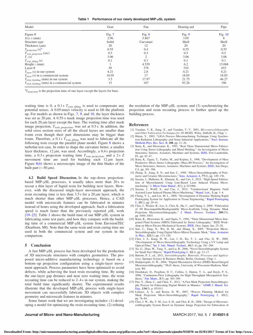
4.2 Build Speed Discussion. In the top–down projection-based MIP-lSL processes, it usually takes more than 20 s torecoat a thin layer of liquid resin for building next layers. How-ever, with the discussed single-layer movement approach, theresin recoating time is less than 3.5 s for a 20 lm layer, which ismuch shorter than other MIP-lSL processes. Hence, a CADmodel with microscale features can be fabricated in minutesinstead of hours using the developed approach. Such a fabricationspeed is much faster than the previously reported lSL work[19–23]. Table 1 shows the build time of our MIP-lSL system infabricating some test parts, and how they compare with the build-ing time of a commercial MIP-lSL system from EnvisionTEC(Dearborn, MI). Note that the same resin and resin curing time areused in both the commercial system and our system in thecomparison.
5 Conclusion
A fast MIP-lSL process has been developed for the productionof 3D microscale structures with complex geometries. The pro-posed micro-additive manufacturing technology is based on abottom–up projection configuration using a single-layer move-ment approach. Process parameters have been optimized to avoiddefects, while achieving the least resin recoating time. By usingthe one-layer gap distance and near zero waiting time, the resinrecoating time can be reduced to 2–4 s in our system, making thetotal build time significantly shorter. The experimental resultsillustrate that the developed MIP-lSL process with single-layermovement can successfully fabricate 3D objects with complexgeometry and microscale features in minutes.
Some future work that we are investigating includes: (1) devel-oping a model for optimizing the resin recoating time, (2) refining
the resolution of the MIP-lSL system; and (3) synchronizing theprojection and resin recoating process to further speed up thebuilding process.
References[1] Varadan, V. K., Jiang, X., and Varadan, V. V., 2001, Microstereolithography
and Other Fabrication Techniques for 3D MEMS, Wiley, DeKalb, IL, Chap. 1.[2] Hirata, Y., 2003, “LIGA Process–Micromachining Technique Using Synchro-
tron Radiation Lithography–and Some Industrial Applications,” Nucl. Instrum.Methods Phys. Res. Sect. B, 208, pp. 21–26.
[3] Ikuta, K., and Hirowatari, K., 1993, “Real Three Dimensional Micro Fabrica-tion Using Stereo Lithography and Metal Molding,” An Investigation of MicroStructures, Sensors, Actuators, Machines and Systems, IEEE, Fort Lauderdale,FL, pp. 42–47.
[4] Ikuta, K., Ogata, T., Tsubio, M., and Kojima, S., 1996, “Development of MassProductive Micro Stereo Lithography (Mass-IH Process),” An Investigation ofMicro Structures, Sensors, Actuators, Machines and Systems, IEEE, San Diego,CA, pp. 301–306.
[5] Zhang, X., Jiang, X. N., and Sun, C., 1999, “Micro-Stereolithography of Poly-meric and Ceramic Microstructures,” Sens. Actuators A, 77(2), pp. 149–156.
[6] Saxena, I., Malhotra, R., Ehmann, K., and Cao, J., 2015, “High-Speed Fabrica-tion of Microchannels Using Line-Based Laser Induced Plasma Micro-machining,” J. Micro Nano Manuf., 3(2), p. 021006.
[7] Saxena, I., Wolff, S., and Cao, J., 2015, “Unidirectional Magnetic FieldAssisted Laser Induced Plasma Micro-Machining,” Manuf. Lett., 3, pp. 1–4.
[8] Cheng, Y. L., and Lee, M. L., 2009, “Development of Dynamic Masking RapidPrototyping System for Application in Tissue Engineering,” Rapid PrototypingJ., 15(1), pp. 29–41.
[9] Choi, J., Wicker, R., Lee, S., Choi, K., Ha, C., and Chung, I., 2009, “Fabricationof 3D Biocompatible/Biodegradable Micro-Scaffolds Using Dynamic MaskProjection Microstereolithography,” J. Mater. Process. Technol., 209(15),pp. 5494–5503.
[10] Ikuta, K., Hirowatari, K., and Ogata, T., 1994, “Three Dimensional Micro Inte-grated Fluid Systems (MIFS) Fabricated by Stereo Lithography,” IEEE Work-shop on Micro Electro Mechanical Systems, IEEE, Oiso, Japan, Jan. 25–28.
[11] Sun, C., Fang, N., Wu, D. M., and Zhang, X., 2005, “Projection Micro-Stereolithography Using Digital Micro-Mirror Dynamic Mask,” Sens. ActuatorsA: Phys., 121(1), pp. 113–120.
[12] Choi, J. S., Kang, H. W., Lee, I. H., Ko, T. J., and Cho, D. W., 2009,“Development of Micro-Stereolithography Technology Using a UV Lamp andOptical Fiber,” Int. J. Adv. Manuf. Technol., 41(3–4), pp. 281–286.
[13] Xu, G., Zhao, W., Tang, Y., and Lu, B., 2006, “Novel Stereolithography Systemfor Small Size Objects,” Rapid Prototyping J., 12(1), pp. 12–17.
[14] B�artolo, P. J., ed., 2011, Stereolithography: Materials, Processes and Applica-tions, Springer Science & Business Media, Berlin, Germany, Chap. 1.
[15] Hadipoespito, G. W., 2004, “Digital Micromirror Device (DMD) Based IntegralMicrostereolithography,” Ph.D. thesis, University of Wisconsin-Madison, Mad-ison, WI.
[16] Dendukuri, D., Pregibon, D. C., Collins, J., Hatton, T. A., and Doyle, P. S.,2006, “Continuous-Flow Lithography for High-Throughput Microparticle Syn-thesis,” Nat. Mater., 5(5), pp. 365–369.
[17] Pan, Y., Zhou, C., and Chen, Y., 2012, “A Fast Mask Projection Stereolithogra-phy Process for Fabricating Digital Models in Minutes,” ASME J. Manuf. Sci.Eng., 134(5), p. 051011.
[18] Limaye, A. S., and Rosen, D. W., 2007, “Process Planning Method forMask Projection Micro-Stereolithography,” Rapid Prototyping J., 13(2),pp. 76–84.
[19] Choi, J. W., Ha, Y. M., Lee, S. H., and Choi, K. H., 2006, “Design of Microster-eolithography System Based on Dynamic Image Projection for Fabrication of
Table 1 Performance of our newly developed MIP-lSL system
Model Gear Fan Hearing-aid Pipe
Figure # Fig. 7 Fig. 8 Fig. 9 Fig. 10Size x (mm) 2.96 5.867 3.05 8Structure type Solid Curvature Shell ShellThickness (lm) 20 12 20 20Tprojection (s)a 0.55 0.4 0.55 0.55Twait_projection (sec) 0.5 0.3 0.5 0.5Tz (s) 3.06 2 3.06 3.06Twait_filling (s) 0.1 0.1 0.1 0.1Height z (mm) 1 4.539 6.2 13.068Layer # 50 378 310 653Tlayer (s) in our system 4.21 2.8 4.21 4.21Tlayer (s) in a commercial system 18.05 17 18.05 18.05Ttotal_building (min) in our system 3.5 17.97 21.75 46.27Ttotal_building (min) in a commercial system 15 107 93.26 196
aTprojection is the projection time of one layer except the layers for base.
Journal of Micro- and Nano-Manufacturing MARCH 2017, Vol. 5 / 014501-5
Downloaded From: http://micronanomanufacturing.asmedigitalcollection.asme.org/pdfaccess.ashx?url=/data/journals/ajmnbt/935870/ on 02/03/2017 Terms of Use: http://www.asme.org/about-asme/terms-of-use

Three-Dimensional Microstructures,” J. Mech. Sci. Technol., 20(12),pp. 2094–2104.
[20] Takagi, T., and Nakajima, N., 1994, “Architecture Combination by Micro Pho-toforming Process,” IEEE Workshop on Micro Electro Mechanical Systems,IEEE, Oiso, Japan, pp. 211–216.
[21] Bertsch, A., Bernhard, P., Vogt, C., and Renaud, P., 2000, “Rapid Prototypingof Small Size Objects,” Rapid Prototyping J., 6(4), pp. 259–266.
[22] Monneret, S., Loubere, V., and Corbel, S., 1999, “MicrostereolithographyUsing a Dynamic Mask Generator and a Noncoherent Visible Light Source,”Design, Test, and Microfabrication of MEMS/MOEMS, International Societyfor Optics and Photonics, Paris, France, pp. 553–561.
[23] Monneret, S., Provin, C., and Le Gall, H., 2001, “Micro-Scale Rapid Prototypingby Stereolithography,” 8th IEEE International Conference on Emerging Technol-ogies and Factory Automation, Juan les Pins, France, Vol. 2, pp. 299–304.
014501-6 / Vol. 5, MARCH 2017 Transactions of the ASME
Downloaded From: http://micronanomanufacturing.asmedigitalcollection.asme.org/pdfaccess.ashx?url=/data/journals/ajmnbt/935870/ on 02/03/2017 Terms of Use: http://www.asme.org/about-asme/terms-of-use


![PTMC: MICROFABRICATION & STEREOLITHOGRAPHY · Stereolithography is a form of prototyping that has been shown to be very versatile with highest accuracy and precision.[11] Stereolithography](https://static.fdocuments.in/doc/165x107/605ef4b2b0307a40e8391640/ptmc-microfabrication-stereolithography-stereolithography-is-a-form-of-prototyping.jpg)