Fast Continuous Collision Detection and Handling for ...
21
HAL Id: inria-00390352 https://hal.inria.fr/inria-00390352 Submitted on 2 Jun 2009 HAL is a multi-disciplinary open access archive for the deposit and dissemination of sci- entific research documents, whether they are pub- lished or not. The documents may come from teaching and research institutions in France or abroad, or from public or private research centers. L’archive ouverte pluridisciplinaire HAL, est destinée au dépôt et à la diffusion de documents scientifiques de niveau recherche, publiés ou non, émanant des établissements d’enseignement et de recherche français ou étrangers, des laboratoires publics ou privés. Fast Continuous Collision Detection and Handling for Desktop Virtual Prototyping Stephane Redon To cite this version: Stephane Redon. Fast Continuous Collision Detection and Handling for Desktop Virtual Prototyping. Virtual Reality, Springer Verlag, 2004, 8 (1), pp.63-70. 10.1007/s10055-004-0138-9. inria-00390352
Transcript of Fast Continuous Collision Detection and Handling for ...
HAL Id: inria-00390352https://hal.inria.fr/inria-00390352
Submitted on 2 Jun 2009
HAL is a multi-disciplinary open accessarchive for the deposit and dissemination of sci-entific research documents, whether they are pub-lished or not. The documents may come fromteaching and research institutions in France orabroad, or from public or private research centers.
L’archive ouverte pluridisciplinaire HAL, estdestinée au dépôt et à la diffusion de documentsscientifiques de niveau recherche, publiés ou non,émanant des établissements d’enseignement et derecherche français ou étrangers, des laboratoirespublics ou privés.
Fast Continuous Collision Detection and Handling forDesktop Virtual Prototyping
Stephane Redon
To cite this version:Stephane Redon. Fast Continuous Collision Detection and Handling for Desktop Virtual Prototyping.Virtual Reality, Springer Verlag, 2004, 8 (1), pp.63-70. �10.1007/s10055-004-0138-9�. �inria-00390352�

Fast Continuous Collision Detection and Handling
for Desktop Virtual Prototyping
Stephane Redon
i3D - INRIA - France∗ †
Abstract
This paper presents an overview of our recent work on continuous collision de-
tection methods and constraints handling for rigid polyhedral objects. We demon-
strate that continuous collision detection algorithms are practical in interactive dy-
namics simulation of complex polyhedral rigid bodies and show how continuous col-
lision detection and efficient constraint-based dynamics algorithms allow to perform
various virtual prototyping tasksintuitively, precisely and robustlyon commodity
desktop computers. Especially, we present two applications of our system to actual
industrial cases. We note that both tasks are performed with a simple 2d mouse on a
high-end computer.
1 Introduction
Computer aided design and manufacturing has been a very active research field for
many years, which has contributed to the development of major product lifecycle man-
∗The author is currently affiliated with the University of North Carolina at Chapel Hill.†Correspondence and offprint requests to: Stephane Redon, Department of Computer Science,
336 Sitterson Hall, CB] 3175 University of North Carolina Chapel Hill, NC 27599-3175. Email: [email protected].
1

agement softwares.
One important aspect of product lifecycle management isvirtual prototyping, which
aims at designing manufactured products throughdigital mock-ups, in order to suppress
the need for expensive real mock-ups. Because the analysis and simulation of a product
through a digital mock-up must provide insight on the productbeforeit is manufactured,
virtual prototyping requires to be able to simulate the physical properties of the objects
being designed.
This paper focuses on a fundamental requirement of virtual prototyping: the ability
to detectandhandlecollisions between virtual objects. Typical applications of collision
detection and handling in virtual prototyping include path-planning, tolerance verification
and assembly/disassembly tasks conception.
Most well-known collision detection methods arediscrete: they sample the objects’
trajectories at discrete times and reportinterpenetrationsonly (recent surveys include
[11, 13]). As a result, they can miss collisions when the objects move rapidly or are
small. Moreover, even when an interpenetration has been detected, it is often difficult to
reposition the objects in acontactingposition (i.e. with no interpenetration). One rea-
son being that computing the penetration depth for general objects is a difficult problem,
which does not take the objects’ motion into account. Relying on the penetration depth
to reposition the objects might thus lead to the well-knownpop-througheffect, where an
object enters an obstacle on one side and goes out of it on the other side, as can be seen
in Figure 1.
Evenbacktracking methods, which attempt to compute the first time of collision by
recursively subdividing the time interval after an interpenetration has been detected, can
fail when the object is not connected. Assume that the current time interval is[tn, tn+1],
and assume an interpenetration has been detected at timetn+1 Essentially, one time of
first contactte is estimatedin this interval (for example, by taking the midpoint of the
2
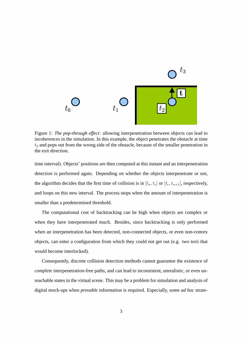
Figure 1:The pop-through effect: allowing interpenetration between objects can lead toincoherences in the simulation. In this example, the object penetrates the obstacle at timet2 and pops out from the wrong side of the obstacle, because of the smaller penetration inthe exit direction.
time interval). Objects’ positions are then computed at this instant and an interpenetration
detection is performed again. Depending on whether the objects interpenetrate or not,
the algorithm decides that the first time of collision is in[tn, te] or [te, tn+1], respectively,
and loops on this new interval. The process stops when the amount of interpenetration is
smaller than a predetermined threshold.
The computational cost of backtracking can be high when objects are complex or
when they have interpenetrated much. Besides, since backtracking is only performed
when an interpenetration has been detected, non-connected objects, or even non-convex
objects, can enter a configuration from which they could not get out (e.g. two torii that
would become interlocked).
Consequently, discrete collision detection methods cannot guarantee the existence of
completeinterpenetration-free paths, and can lead to inconsistent, unrealistic, or even un-
reachable states in the virtual scene. This may be a problem for simulation and analysis of
digital mock-ups whenprovableinformation is required. Especially, somead hocstrate-
3

gies have sometimes to be defined when using a discrete collision detection method in
a virtual prototyping context in order to attempt to guarantee interpenetration-free paths.
One of them consists in not moving the object when the next position involves a penetra-
tion. While this may be sufficient when few obstacles only surround the moving object,
this may lead to an impossibility of manipulating the object when the environment is clut-
tered. Moreover, this method guarantees interpenetration-freepositionsonly, as collisions
can still be missed. Other strategies consist in using force fields and haptic interface to
guarantee that the manipulated object remains far from the environment.
In the following, we present an overview of our recent work oncontinuouscollision
detection methods and constraints handling for rigid polyhedral objects. We demonstrate
that continuous collision detection algorithms are possible in interactive dynamics simu-
lation of rigid bodies and show how continuous collision detection and constraint-based
dynamics algorithms allow to perform various virtual prototyping tasksintuitively, pre-
cisely and robustlyon commodity desktop computers. Especially, we present two appli-
cations of our system to actual industrial cases. We note that both tasks are performed
with a simple 2d mouse.
2 Continuous collision detection
2.1 Arbitrary in-between motion
Despite their shortcomings, it is understandable why discrete collision methods have
been developed and used to such a large extent in dynamics simulations. Besides their
assumed lower cost, it must be noticed that, most of the time,the actual objects’ mo-
tions are not known. One important reason is that the differential equations governing
the system’s dynamics are solved using discretized methods (e.g. Euler or Runge-Kutta
schemes). Another reason is that, in an interactive application, the user interface (e.g. the
4
mouse, or a haptic device) sends the user’s actions to the system at discrete instants only.
Other interfaces such as tracking systems, which are not necessarily interactive, also pro-
vide discretized data only. For all these reasons, it is most of the time impossible to have a
closed-form expression of the objects’ motions, and the objects’ positions, velocities and
accelerations are available at discrete times only.
Because the actual motion of an object is not known, we have proposed to replace it
by anarbitrary in-between motion, which interpolates successive available data to pro-
duce a continuous object motion [20, 23]. Thanks to the interpolation, the global aspect of
the objects’ trajectories is conserved, while thelocal motion (the unknown one, between
two available positions) is modified. The continuous object motion is used both for col-
lision detection and object positioning when a collision has been detected, to ensure that
the scene is always in a consistent state, without any interpenetration. The choice of the
in-between motion depends on the application. It must be general enough to satisfy the
various constraints imposed by the application (e.g. objects rigidity, ability to reach any
configuration required in the application), but at the same time must be such that the con-
tinuous collision detection equations can be solved very efficiently. Any motion meeting
these requirements can bearbitrarily chosen. Note that the interpolation order depends
on the application as well. While it may be sufficient to interpolate positions only, some
applications may require higher-order interpolations.
It can be argued that using an interpolating motion which has been arbitrarily chosen
does not allow to determine the exact collision times and positions corresponding to the
actual objects’ motions. Obviously, using an arbitrary in-between motion only allows
to report those collisions which occurwhen the objects move according to this arbitrary
motion. However, by using the same arbitrary motion to place the objects at the time of
collision, the virtual scene is always in a consistent state, andno interpenetration ever
occurs. Moreover, this method guarantees interpenetration-freepaths, and not only con-
5

sistent positions at discrete times.
2.2 Elementary tests
Since we perform continuous collision detection tests, only three types of contact can
occur between two general polyhedral objectsi andj:
• An edge ofi contacts an edge ofj
• A face ofi contacts a vertex ofj
• A vertex ofi contacts a face ofj
The last two contact types are equivalent and we thus have to perform two different types
of elementary tests: edge/edge or vertex/face tests. The continuous collision detection
equations for both tests are derived simply. Whatever the motions of objectsi andj, a
collision occurs between an edgea(t)b(t) of i and an edgec(t)d(t) of j if there exists a
time t for which:
a(t)c(t).(a(t)b(t) ∧ c(t)d(t)) = 0 (1)
which means that the lines containing the edges are colliding, and if at that time theedges
(not only the lines) are intersecting. Similarly, a collision occurs between a vertexa(t) of
i (respj.) and a triangleb(t)c(t)d(t) of j (resp.i) if there is a timet for which:
a(t)b(t).(b(t)c(t) ∧ b(t)d(t) = 0 (2)
which means that the vertex is inside the plane containing the triangle, and if at that time
the vertex isinside the triangle. Equations (1) and (2) are the ones which have to be solved
efficiently when a specific interpolating motion is chosen. Our initial work has focused
on these equations to show that using a specific arbitrary in-between motion derived from
a screw motion allowed to reduce them to third-degree polynomial equations when one of
6

the objects is static [20, 21]. A method proposed by Canny in [7] obtains a similar result
with a different motion, but its use of quaternions and of a translation along a different
axis than the one of rotation makes it more computationally expensive to determine the
coefficients of the polynomials.
2.3 Bounding-volumes hierarchies
In order to avoid performing all possible edge/edge or vertex/face face tests for any
object pair, many collision detection algorithms rely onbounding-volume hierarchies.
Basically, if two objects are enclosed in bounding volumes which do not overlap, then
it is known for sure that they do not collide. Hierarchies of bounding volumes are used
to recursively perform such overlap tests which can conservatively cull away large parts
of the objects when testing for a collision. Typical bounding volumes used for collision
detection include spheres [19, 10, 25, 6], axis-aligned bounding boxes (AABBs) [28],
oriented bounding boxes (OBBs) [8], andk-dops [9].
Forcontinuouscollision detection, it is necessary to perform continuous overlap tests
between bounding volumes. We have proposed in [23] to extend the discrete OBB/OBB
overlap test proposed by Gottschalket al. [8] to the continuous domain by usinginterval
arithmetic[17, 26]. The static test relies upon the separating axis theorem. Let us assume
that the first OBB is described by three axese1, e2 ande3, a centerTA, and its half-sizes
along its axesa1, a2 anda3. In the same way, the second OBB is described by its axesf1,
f2 andf3, its centerTB, and its half-sizes along its axesb1, b2 andb3. The separating axis
theorem states that two static OBBs overlap if and only if all of fifteen separating axis
tests fail. A separating test is simple: the axisa separates the OBBs if and only if:
|a ·TATB| >3∑
i=1
ai|a · ei|+3∑
i=1
bi|a · fi| (3)
7

The sufficient set of fifteen axes is:
{ei, fj, ei ∧ fj, 1 6 i 6 3, 1 6 j 6 3} (4)
Since each member of the inequality (3) is a function of time depending on the specific
arbitrary in-between motion chosen for the application, interval arithmetic can be used
to bound both members very efficiently over a time interval[tn, tn+1]. When the lower
bound on the left member is larger than the upper bound on the right member, the axis
a separates the boxes during the whole time interval[tn, tn+1], and the pair of boxes can
thus be discarded. Note that basing the continuous overlap test upon bounds computed
over a whole time interval produces conservative results only: two moving boxes can be
separated over[tn, tn+1] even when there does not existoneaxis which separates them
on the whole time interval. Because of this, we have proposed a heuristic based upon the
boxes’ velocities to determine when it may be useful to subdivide the time interval. This
allows to cull away more pairs of boxes by a better detection of these situations where
more than one axis is required to separate the boxes over the whole time interval.
3 Handling constraints
Closely related to the collision detection problem is the one of handling the geomet-
rical constraints imposed by the collisions which have been detected. In a rigid body
dynamics simulation, two different problems have to be solved:
Collision response problemWhenever a new collision occurs, the simulator must deter-
mine the objects’post-impact velocitiesfrom their pre-impact velocities and their
dynamic properties.
Constrained motion problem When the collision response problem has been solved,
the simulator has to compute the objects’constrained accelerationsfrom their un-
8
constrained accelerations (the ones the objects would have if there weren’t any con-
straints acting on them) and the geometrical constraints imposed by the transient
contacts (those for which the relative velocity is zero,i.e. those which have a non-
zero duration).
Numerous approaches have been suggested to solve both problems and traditional al-
gorithms include penalty methods [18, 12], impulse-based methods [16] and constraint-
based methods [14, 3, 4, 27, 1, 2, 15]. Penalty methods are generally used when no precise
contact information is available, as they compute the contact forces from the amount of
interpenetration between contacting objects. Continuous collision detection naturally pro-
vides all the necessary contact information: the contact position, the contacting elements
and the contact normal. Consequently, impulse-based or constraint-based methods are
a natural choice. We have opted for constraint-based methods because they can handle
simultaneous constraints.
Most constraint-based methods formulate both dynamics problems as a linear com-
plementarity problem (LCP) in thecontact-space, which relates contact forces and accel-
erations. For example, in the frictionless constrained motion problem, the LCP expresses
the relation between the normal contact forces and the relative normal accelerations at the
contact points. Iff andacp are two vectors inIRm describing the normal contact forces (in
a frictionless system, the contact forces are normal to the contact plane) and the normal
relative accelerations to them contact points, then there exists anm×m matrixA and a
vectorb in IRm such as:
acp = Af + b
acp > 0
f > 0
aTcpf = 0
(5)
9

The complementarity relationaTcpf = 0 expresses the fact that, for each contact point,
either the relative normal acceleration is non-zero (the contact breaks) and then the normal
contact force is zero, or the contact force is non-zero (objects remain in contact) and
therefore the relative normal acceleration is zero.
The matrixA is traditional computed from the constraints created by the contact
points [3, 24]. Leti andj denote two contacting objects.I is a contact point,n is the
contact normal directed fromj to i. Depending on the object it belongs to,I is denotedIi
or Ij.
Note that this distinction is necessary to establish the constraint equations. Although
these two points are identical in theory, it is not the case in practice, for example because
of the finite precision of the computations. Moreover, we will see in the next section
that the method we use to combine the continuous collision detection algorithms to the
dynamics algorithms requires us to maintain a distinction betweenIi etIj which become,
in practice, the closest points belonging to the polyhedral primitives. In a vertex/face case,
for example,Ii is the vertex andIj is the point in the face which is the closest toIi.
With this notation, thenon-penetration constrainton the relative normal acceleration
of I is [3]:
(ai(Ii)− aj(Ij)).n + 2.(vi(Ii)− vj(Ij)).dn
dt> 0 (6)
Similarly, acollision response constrainton the relative normal velocity can be derived
when a collision occurs, to solve the collision response problem:
(v+i (Ii)− v+
j (Ij)).n > −e(v−i (Ii)− v−j (Ij)).n (7)
wheree is the restitution coefficient at the contact point.
We have shown in [22] that for frictionless systems Gauss’ least constraint principle
provides amotion-spaceformulation of both dynamics problems, through a projection
10

problem which relates the object’s accelerations or velocities and the contact forces. Al-
though the two formulations are mathematically equivalent, the motion-space formulation
presents several algorithmic benefits: it is better conditioned, always sparse, requires less
memory and allows to avoid some redundant computations performed by an algorithm
operating in the contact-space. An experimental comparison has suggested that an algo-
rithm operating in the motion-space takes advantage of sparsity to perform increasingly
better than a contact-space algorithm as the average number of contact points per object
increases. As a result, our system uses a motion-space algorithm based upon Wilhelm-
sen’s projection algorithm [29].
4 Combining continuous collision detection and response
Because we use an arbitrary in-between motion to interpolate successive objects’ po-
sitions, we need to permanently maintain a smallsecurity distancebetween contacting
objects. Most of the time, indeed, the arbitrarily chosen in-between motion does not
satisfy the dynamics constraints during the successive time intervals.
Consider for example the case of a rectangular box in transient contact with a plane
surface, as visible in Figure 2.a. In this example, the contact pointI should be perma-
nently on the contact planeP during the considered time interval[tn, tn+1]. However,
the real object motion during this time interval is replaced by an arbitrarily fixed motion
which, although it preserves the object’s positions at timestn andtn+1, does not guarantee
that the pointI remains on the planeP during the time interval. Depending on the initial
and final positions of the box, which impose the in-between motion used for the collision
detection, this pointI might indeed violate the non-penetration constraintimmediately af-
ter tn, leading to the detection of a collision at timetn. In order to avoid that the simulator
remains blocked at timetn or, generally, that it detects these collisions artificially created
by the use of an arbitrary in-between motion too often, we introduce a security distance
11

Figure 2: a: the arbitrary in-between motion used for the collision detection does notsatisfy the non-penetration constraint during the time interval[tn, tn+1]. b: contactingobjects are maintained slightly distant from each other.
12

εs between contacting objects, as shown in Figure 2.b. As a result, we consider that each
contact point which has been determined by the continuous collision detection module
is characterized by two pointsIi andIj which are the closest points on the polyhedral
primitives. These closest points are easily updated whenever the geometrical constraints
are modified, as long as a contact is considered to be active.
In order to maintain the security distance between contacting objects over time, the
constraints imposed to accelerations or velocities are modified slightly. For example,
when the local distance between the two objects (i.e. the one separating the two pointsIi
andIj which characterize the contact point) is smaller than the security distanceεs, the
non-penetration constraint (6) becomes:
ai(Ii)− aj(Ij)).n + 2.(vi(Ii)− vj(Ij)).dn
dt> K + k(εs − d) (8)
wherek is a coupling constant, andd is the distance between the pointsIi andIj.
Two other values,εb and εr, are used in combination with the security distanceεs.
The first one,εb, larger thanεs, is the value beyond which the simulator declares that
the contact between the two objects is broken (thus removing the need to updateIi and
Ij). The second,εr, smaller thanεs, is an alert value below which the simulator stops the
simulation time and enters arepositioning cycle, because it did not manage to maintain the
objects at a sufficient distance from each other during the simulation. This repositioning
cycle, similar to the one introduced by Baraff in [4], is performed between two successive
frames by computing the smallest objects’ displacements which satisfy therepositioning
constraints. The repositioning constraints are similar to collision response constraints (7)
which become:
(vi(Ii)− vj(Ij)).n > εs − d. (9)
Once these velocities are computed, they are used to move objects (while detecting colli-
13
sions). As long as there exists a contact for which the local distance is below the reposi-
tioning distanceεr, a new repositioning step is done. We have observed that repositioning
cycles are generally very short, nearly imperceptible by the user, and do not hinder the
progression of the interactive simulation.
Let us note that the repositioning problem is very similar to the collision response
problem, since it consists in computing the smallest possible velocities, in the velocity-
space, among those which satisfy the repositioning constraints.
In our implementation, objects are scaled so that the total width of the environment
is 50 units, and the coupling parameters areεr = 0.0044, εs = 0.01, andεb = 0.023.
As a consequence, the security distance and the repositioning effects are not perceived
by the user. Let us note that, for environments including mobile objects of very disparate
sizes, it is possible to adapt these coupling values to the manipulated object during the
interaction, in order to avoid that the size of the object manipulated be of the same order
than the security distance. For the databases we tested, however, this was not necessary.
Let us note finally that repositioning objects does not correspond to a physical phe-
nomenon, and can add energy in the system. In order to avoid this, it may be useful to
slightly decrease the objects’ velocities after a repositioning step. Note however that this
problem does not occur in a first-order (quasi-static) simulation, since objects’ velocities
are zeroed at each frame.
More generally, the repositioning problem is similar to a constraint stabilization prob-
lem, for which a classic solution is the one proposed by Baumgarte [5]. In this case,
however, constraints are unilateral ones. Moreover, the more difficult problem of unilat-
eral constraint stabilization is greatly facilitated by the continuous collision detection.
14

5 Results
The algorithms reported here have been integrated to form a portable C++ library,
CONTACT Toolkit, which has been successfully tested on Windows and Unix environ-
ments. The resulting simulator is able to perform interactive simulations on polyhedral
objects which contain up to a few hundreds of thousands of triangles on a 2GHz pentium
PC with 256 Megabytes of memory and a NVIDIA GeForce4 MX graphics card.
Figure 3: Interactive positioning of a car door (11,000 triangles) on a car skeleton(130,000 triangles). Continuous collision detection algorithms and constraint-based dy-namics algorithms allow to place the car door precisely and interactively, without anyinterpenetration ever. 3d modelsc©Renault.
Here we present two applications of our system to actual industrial databases provided
by Renault. We note that for many virtual prototyping tasks it is preferable to perform
first-order (quasi-static) simulations, where the objects have no acceleration, as the ab-
sence of inertia generally facilitates the manipulation of the objects. This is done by
zeroing the objects velocities at each time step and using collision response constraints
only [22].
The first application involves positioning a car door (11,000 triangles) into the corre-
sponding car skeleton (130,000 triangles). Figure 3 shows a typical positioning sequence.
Our tests demonstrate that a user can easily position the door with a few mouse motions.
15

The interaction is greatly facilitated by the constraint-based algorithms. The continuous
collision algorithms allow the user to precisely position the door, as contacts are detected
with the exact objects’ geometry, without ever letting them interpenetrate.
The second application consists in removing a window motor from a car door (about
20,000 triangles in the scene). Figure 4 shows a typical interaction sequence. The contact
points occurring during the interaction are materialized by small yellow spheres. Again,
this application demonstrates the quality of the interaction provided by continuous colli-
sion detection algorithms and constraint-based dynamics algorithms. The window motor
is very easily removed from the car door with a few mouse motions.
We note that in both cases, the interactive simulator allows toguaranteecomplete
interpenetration-free paths, and that both tasks are performed with a simple mouse on a
high-end PC.
Figure 4:Determining the existence of a path to remove the window motor from the cardoor. The continuous collision detection algorithms allow to guarantee the existence ofan interpenetration-free path to remove the motor while interactively and intuitively ma-nipulating the motor thanks to efficient constraint-based dynamics algorithms. 3d modelsc©Renault.
Our tests also show that a user does not notice the fact that an arbitrary in-between
motion is employed to replace the actual objects’ motions between successive frames.
16
6 Conclusion and future work
This paper has presented an overview of our recent work on continuous collision de-
tection and constraint handling methods for polyhedral rigid bodies. We have discussed
various shortcomings of discrete collision detection methods, especially in the context
of virtual prototyping, and have described a continuous collision detection method based
upon arbitrary in-between motions. We have shown how this method can be coupled
to constraint-based dynamics algorithms. Our tests show that the simulator based upon
the algorithms reported in this paper can be used for interactive dynamics simulations of
complex polyhedral rigid bodies. Moreover, we have presented the applicability of our
algorithms to actual industrial cases provided by Renault, which seem to demonstrate that
continuous collision detection algorithms combined to efficient constraint-based dynam-
ics algorithms can be a powerful tool for virtual prototyping tasks.
Future work include in-depth tests of our simulator. The library CONTACT Toolkit
is currently being tested at Renault, PSA Peugeot Citroën and Airbus-EADS. This should
help to evaluate more precisely the validity and the scalability of the algorithms reported
in this paper.
Also, some manufacturing tasksrequire a haptic feedback (training applications for
example). We would like to study the benefits of continuous collision detection algorithms
in this context.
References
[1] M. Anitescu and F. A. Potra. Formulating Dynamic Multi-Rigid-Body Contact Prob-
lems with Friction as Solvable Linear Complementarity Problems. Nonlinear Dy-
nam. 14 (1997), no. 3, 231–247.
17

[2] M. Anitescu, F. A. Potra and D. E. Stewart. Time-stepping for Three-dimensional
Rigid Body Dynamics. Computational Modeling of Contact and Friction. Comput.
Methods Appl. Mech. Engrg. 177 (1999), no. 3-4, 183–197.
[3] D. Baraff. Fast Contact Force Computation for Nonpenetrating Rigid Bodies. In
SIGGRAPH 94 Conference Proceedings, Annual Conference Series, pp 23-34.
ACM SIGGRAPH, Addison Wesley, 1994.
[4] D. Baraff. Interactive Simulation of Solid Rigid Bodies. IEEE Computer Graphics
and Applications, 15(3), pp 63-75, May 1995.
[5] J. Baumgarte. Stabilization of constraints and integrals of motion in dynamical sys-
tems. Comp. Meth. in Appl. Mech. and Eng., 1:1-16, 1972.
[6] G. Bradshaw and C. O’Sullivan. Sphere-Tree Construction using Dynamic Medial
Axis Approximation. In Proceedings of ACM Symposium on Computer Animation
2002.
[7] J. F. Canny. collision detection for moving polyhedra. IEEE Trans. Patt. Anal. Mach.
Intell. 8,2 (March 1986), pp 200-209.
[8] S. Gottschalk, M. C. Lin, and D. Manocha. OBB-Tree: A Hierarchical Structure for
Rapid Interference Detection. In SIGGRAPH 96 Conference Proceedings, Annual
Conference Series. ACM SIGGRAPH, Addison Wesley, August 1996.
[9] J.T. Klosowski, M. Held, J.S.B. Mitchell, H. Sowizral and K. Zikan. Efficient colli-
sion Detection Using Bounding Volume Hierarchies of k-DOPs. IEEE Transactions
on Visualization and Computer Graphics, March 1998, Volume 4, Number 1.
[10] P. M. Hubbard. Collision detection for interactive graphics applications. Ph.D. The-
sis, April 1995.
18

[11] P. Jiménez, F. Thomas and C. Torras. 3D collision detection: a survey. Computers
and Graphics, 25 (2), pp. 269-285, (April 2001), Pergamon Press / Elsevier Science.
[12] M. McKenna and D. Zeltzer. Dynamic simulation of autonomous legged locomo-
tion. In Computer Graphics (Proc. SIGGRAPH), volume 24, pages 29-38. ACM,
August 1990.
[13] Ming Lin and Dinesh Manocha. Collision and Proximity Queries. Handbook of Dis-
crete and Computational Geometry: Collision detection, 2003 (to appear).
[14] P. Lötstedt. Numerical simulation of time-dependent contact friction problems in
rigid body mechanics. SIAM Journal of Scientific Statistical Computing, vol. 5, no.
2, pp. 370- 393, 1984.
[15] V. J. Milenkovic and H.Schmidl. Optimization Based Animation. SIGGRAPH 2001
[16] B. Mirtich and J. Canny. Impulse-based Simulation of Rigid Bodies. In Proceedings
of Symposium on Interactive 3D Graphics, 1995.
[17] R. E. Moore. Interval analysis and automatic error analysis in digital computation.
PhD Thesis, Stanford University, October 1962.
[18] M. Moore and J. Wilhelms. Collision Detection and Response for Computer Anima-
tion. In Computers Graphics (Proceedings of SIGGRAPH 88), Annual Conference
Series, pp 289-298. ACM SIGGRAPH, August 1988.
[19] S. Quinlan. Efficient distance computation between non-convex objects. In Proceed-
ings of International Conference on Robotics and Automation, pp 3324-3329, 1994.
[20] S. Redon, A. Kheddar, and S. Coquillart. An algebraic solution to the problem
of collision detection for rigid polyhedral objects. Proc. of IEEE Conference on
Robotics and Automation, 2000.
19
[21] S. Redon, A. Kheddar and S. Coquillart. CONTACT: arbitrary in-between motions
for continuous collision detection. In Proceedings of IEEE ROMAN’2001, Sep.
2001.
[22] S. Redon, A. Kheddar and S. Coquillart. Gauss’ least constraint principle and rigid
body simulations. In Proceedings of IEEE International Conference on Robotics and
Automation, May 2002.
[23] S. Redon, A. Kheddar, and S. Coquillart. Fast continuous collision detection be-
tween rigid bodies. Proc. of Eurographics (Computer Graphics Forum), 2002.
[24] D. Ruspini and O. Khatib. Collision/Contact Models for the Dynamic Simulation of
Complex Environments. IEEE/RSJ International Conference on Intelligent Robots
and Systems:IROS’97.
[25] D. C. Ruspini, K. Kolarov and O. Khatib. The Haptic Display of Complex Graphical
Environments. Computer Graphics Proceedings, SIGGRAPH 97 pp 345-52
[26] J. Snyder. Interval analysis for Computer Graphics. Computer Graphics, 26(2),
pages 121-130, July 1992.
[27] D. E. Stewart and J. C. Trinkle. An Implicit Time-Stepping Scheme for Rigid Body
Dynamics with Inelastic collisions and Coulomb Friction. International Journal of
Numerical Methods in Engineering, 39:2673-2691, 1996.
[28] G. Van den Bergen. Efficient collision detection of complex deformable models us-
ing AABB trees. Journal of Graphics Tools, 2(4):1-14, 1997.
[29] D. R. Wilhelmsen. A Nearest Point Algorithm for Convex Polyhedral Cones and
Applications to Positive Linear Approximations. Mathematics of computation, 30,
pp 48-57, 1976.
20