Fast Accurate Surface Metrology - Bruker · Process Monitoring, QA/QC Operations: Faster Metrology...
32
Time To Data: Fast, Accurate Surface Metrology with 3D Microscopes 28 March 2012
Transcript of Fast Accurate Surface Metrology - Bruker · Process Monitoring, QA/QC Operations: Faster Metrology...

Time To Data: Fast, Accurate Surface Metrology with 3D Microscopes 28 March 2012

Outline
• Why the “need for speed”?
• Brief list of inspection methods
• Bruker’s 3D microscopes based on WLI – Overview
• Measurement setup/analyses to optimize time to (good) data
• Conclusion
3/28/2012 2

Process Monitoring, QA/QC Operations: Faster Metrology Saves Time and Money!
• Throughput and accuracy are key to proper monitoring
• GR&R capability also drives successful process metrology
• Bruker 3D microscopes are an excellent choice for in-line monitoring • Tabletop ContourGT-K
• Floor-standing ContourGT-X
3/28/2012 3
ContourGT-K
ContourGT-X

Process Monitoring, QA/QC Operations: Faster Metrology Saves Time and Money!
• In line process control metrology could help monitor depth, diameters, spacings…
3/28/2012 4

Process Monitoring, QA/QC Operations: Faster Metrology Saves Time and Money!
• In line process control metrology can help in reducing waste, lowering material cost
Thermal spray coats – can be monitored for coating uniformity and dimensions, texture, especially functional coats
3/28/2012 5

Some Inspection Techniques Commonly Chosen
• Bright Field Microscope • Stylus Profiler (2D) • Laser line scanner • SEM • AFM • 3D Microscope
• If speed is key, the 3D
microscope offers some key benefits for a vast array of applications
3/28/2012 6
3D Microscope

3D Optical Microscope Provides Fast, Accurate Data – WLI Inside!
• 3D microscope with continuous calibration
• Diagram outlines basic operation for sample measurement (based on WLI)
• This type of system provides fast, accurate data (with fraction of nm vertical resolution)
3/28/2012 7
Sample
Beamsplitter
Illuminator
Reference signal
detector(s)
CCD Reference signal module
Laser
Mirror on the scanner
Reference mirror
Measurement Signals
Mirror

3D Optical Microscope Time to Data: Outline of Steps to Optimize Time
Optimize Time to (good) Data Can be accomplished via proper: • Sample mounting, preparation
• Low sample prep (usually none) on Bruker 3D microscopes • Vacuum fixtures can allow for quick, repeatable mounting
• Hardware setup, measurement options, speeds, etc.
• Data Capture: Automation, stitching, autoscan, (check!)
• Analysis of data
3/28/2012 8

3D Optical Microscope Time to Data: Outline of Steps to Optimize Time
Optimize Time to (good) Data Can be accomplished via proper: • Sample mounting, preparation
• Low sample prep (usually none) on Bruker 3D microscopes • Vacuum fixtures can allow for quick, repeatable mounting
• Hardware setup, measurement options, speeds, etc.
• Data Capture: Automation, stitching, autoscan, (check!)
• Analysis of data – automate if possible
3/28/2012 9
Focus on these items
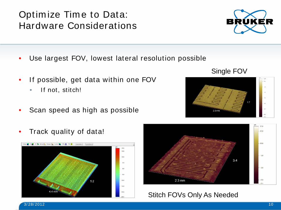
Optimize Time to Data: Hardware Considerations
• Use largest FOV, lowest lateral resolution possible
• If possible, get data within one FOV • If not, stitch!
• Scan speed as high as possible
• Track quality of data!
3/28/2012 10
Single FOV
Stitch FOVs Only As Needed

Optimize Time to Data: Hardware Considerations
• Use largest FOV, lowest lateral resolution possible • Lower magnification means larger area imaged to CCD • Trade for your application (lateral resolution for speed of acquisition)
• Scan speed as high as possible
• Track quality of data!
3/28/2012 11
Single FOV
Scan speed set by dropdown menu

3D Microscopes Allow Easy Optimization of Speed vs. Data Quality
• Use larger FOV, lower lateral resolution • Meets measurement need for example: printed ink layers in e-
tablet device
3/28/2012 12

Bruker Unique Hardware Capability Spiral Stitching Setup Data Capture
• Gain optimal traversal of circular area of interest
• 3D microscope provides vertical resolution on order of 3 nm for longer scan lengths (VSI)
• Key takeaway - no sacrifice in resolution over stitched area
• Can be set up to teach annuli, rectangular, or circular areas 3/28/2012 13

Optimized Time to Data: Data Capture - Autoscan
3/28/2012 14
• Autoscan shortens unknown measurement times
• Automatically ends VSI measurement at prescribed point in data collection
• Modulation of pixels on CCD
used to set this up
• Can save literally 50% or more time on automated metrology

Optimized Time to Data: Data Capture – Autoscan Off
3/28/2012 15
Scan metal surface without autoscan, 100 micron scan takes ~ 25 seconds at 1x speed (simulated)

Optimized Time to Data: Data Capture – Autoscan Improves Time by 8x
3/28/2012 16
Scan metal surface with autoscan, 100 micron scan ends appropriately and data are had in 3 seconds at 1x speed (simulated)

Autoscan most powerful for large, unknown topography
• Metal sample example – save scan of ~ 90 microns since topography and finishing scan contained in first 10 microns
3/28/2012 17

3D Microscopes System Setup – Hardware and API Software = Easy Automation
• Easy Automation Setup
3/28/2012 18

3D Microscopes System Setup – Hardware and API Software = Easy Automation
• Easy Automation Setup – choose traversal
3/28/2012 19
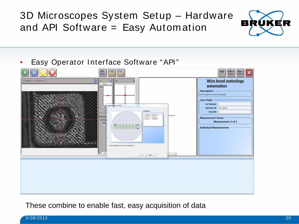
3D Microscopes System Setup – Hardware and API Software = Easy Automation
• Easy Operator Interface Software “API”
3/28/2012 20
These combine to enable fast, easy acquisition of data
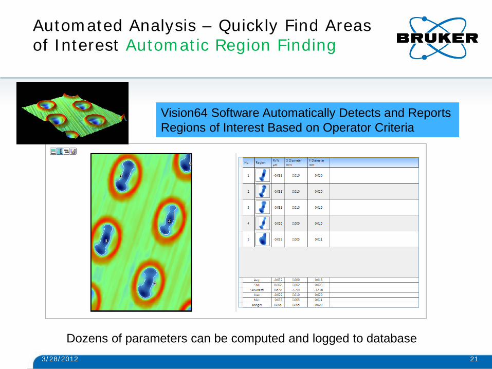
Automated Analysis – Quickly Find Areas of Interest Automatic Region Finding
3/28/2012 21
Vision64 Software Automatically Detects and Reports Regions of Interest Based on Operator Criteria
Dozens of parameters can be computed and logged to database

3D Microscope Measurement Example 20 mm Sample With ~ 0.5mm Topography
• Use relatively large FOV, high scan speed - 23X (around 100 µm/s)
• Use VSI measurement (sample is relatively rough)
• Take advantage of autoscan as described
• Require local Sa, Ra information so need adequate lateral resolution
• Stitch since the area of interest is larger than single FOV for the diameter mentioned
3/28/2012 22

3D Microscope Measurement Example Progress 1
3/28/2012 23

3D Microscope Measurement Example Progress 2..Nearly there!
3/28/2012 24
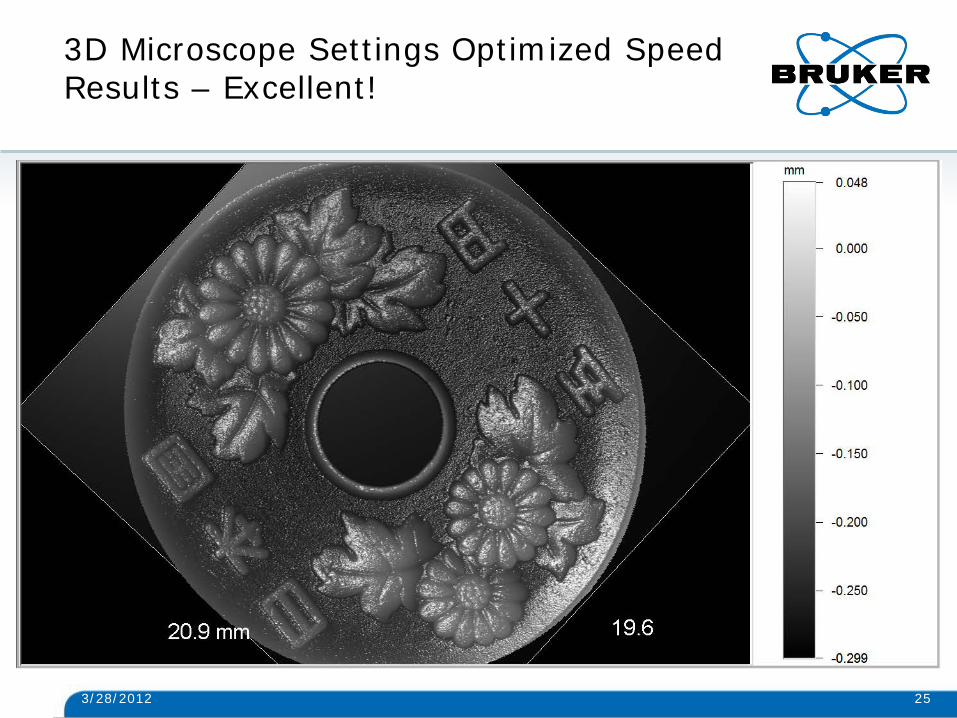
3D Microscope Settings Optimized Speed Results – Excellent!
3/28/2012 25
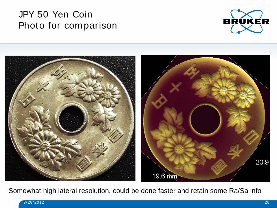
JPY 50 Yen Coin Photo for comparison
3/28/2012 26
Somewhat high lateral resolution, could be done faster and retain some Ra/Sa info

3D Microscope Settings Optimize Speed Detail of Coin
3/28/2012 27

Data obtained are of high quality Examine for roughness, waviness, ISO compliant S parameters – all at once
3/28/2012 28

Simple Software Setup for ISO/ASME Computational Compliance
3/28/2012 29

Conclusion
• Speed (that is, time to good data) can save you money, time and materials
• Bruker 3D optical microscopes are equipped with state of the art
hardware and software to enable operators to efficiently execute on data capture and provide surface heights, texture, roughness
• Analysis software and easy operator interface make reporting of data of interest a straightforward process
• Optimizing speed is a trade – go as fast as you can for good quality data, but no faster!
• Questions? [email protected]
3/28/2012 30

Conclusion
• Questions?
3/28/2012 31
[email protected] Matt Novak, Ph.D. Market Applications Development Manager Bruker Nano Surfaces Division – Stylus and Optical Metrology Tucson, Arizona, USA

www.bruker.com
© Copyright Bruker Corporation. All rights reserved.