World Geography Climates Climates of the world. Warm up List as many climates as you can think of.

ICHE NCE
LIBRARY
A project of Volunteers in Asia
. . . Structures In TraI CII~S. A Textbook for wral Enaineerina and Dearu
Edited By: Lennart P. Bengtsson & James H. Whitaker
Published by: Food and Agriculture Organization of the United Nations Publications Division Via delle Terme di Caracalla 001 Or3 Rome Italy
Available from: UNIPUB 4611-F Assembly Drive Lanham MD 20706-4391 U.S.A.
Reproduced with permission.
Reproduction of this microfiche document in any form is subject to the same restrictions as those of the original document.
IN TROPICAL CLIMATES
FAO/SIDA COOPERATIVE F GRAMME. RURAL STR:JCT’URES IN EAST AND SOUTH-EAST AFRlCA
FOOD AND AGRICULTURE ORGANIZATI\>N OF THE UNITED NATIONS
FAR-M STRUCTURES IN TROPICAL CLIMATES
A Textbook for Structural Engineering and Design
Edited by Lennart P. Bengtsson James H. Whitaker
FAO/SIDA COOPERATIVE PROGRAMME. FOOD AND AGRICULTURE
RURAL STRUCTURES IN EAST AND SOUTH-EAST ORGANIZATION bF THE UNITED NATIONS
Rome, 1986
.4FRICA
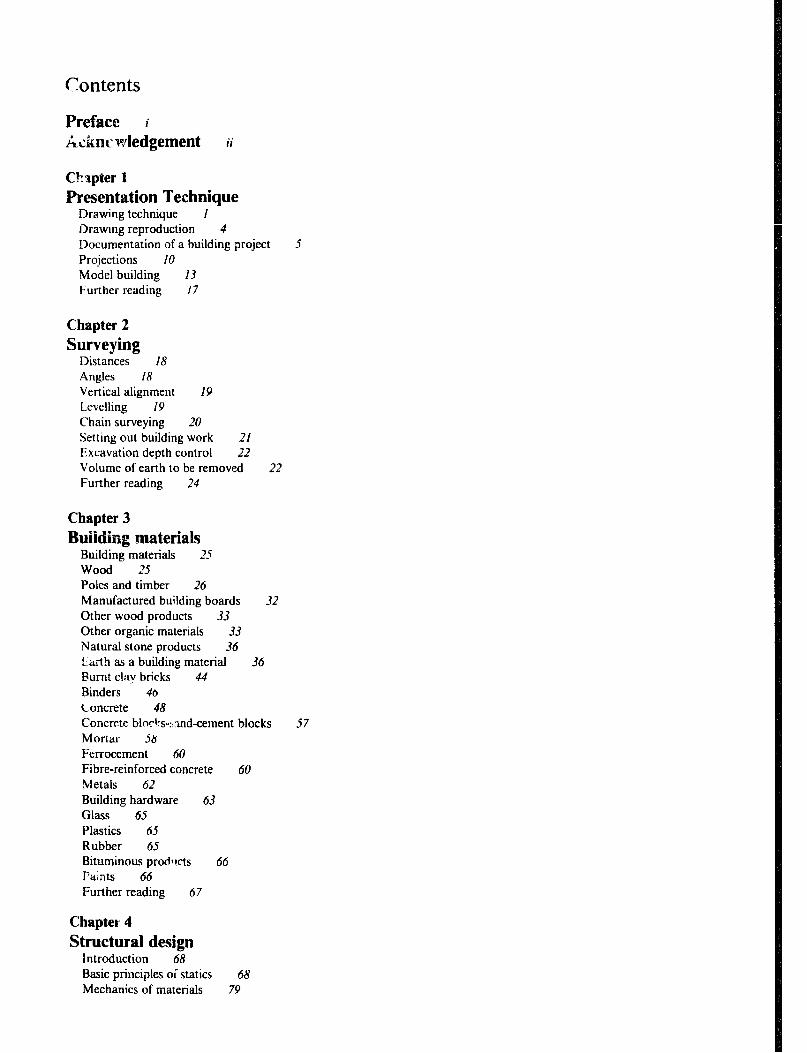
Contents
Preface i A&nc~wledgement ii
CkIpter 1 Presentation Technique
Drawing technique 1 Drawing reproduction 4 Documentation of a building project Projections IO Model building 13 Further reading 17
5
Chapter 2
Surveying Distances 18 Angles I8 Vertical alignment 19 Levelling 19 Chain surveying 20 Setting out building work 21 Excavation depth control i2 Volume of earth to be removed 22 Further reading 24
Chapter 3
Buildiug materials Building materials 25 Wood 25 Poles and timber 26 Manufactured building boards 32 Other wood products 33 Other organic materials 33 Natural stone products 36 Etirth as a building material 36 Punt cl;iv bricks 44 Binders 46 Concrete 48 Concrete blocks-:::ind-cement blocks 57 Mortar 58 Ferrocement 60 Fibre-reinforced concrete 60 Metals 62 Building hardware 63 Glass 65 Plastics 65 Rubber 65 Bituminous prodltcts 66 l%nts 66 Further reading 67
Chapter 4 Structural design
Introduction 68 Basic principles oi statics 68 Mechanics of materials 79
Structural elements and loading 82 Design of members in direct stress 84 Properties of structural sections 86 Design of a simple beam 89 Composite beams 96 Columns 98 Trusses 105 Frames 108 Connections II0 Stability 113 Retaining walls 114 Further reading 119
Chapter 5
Elements of construction Loads on building components I20 Footings and foundations 121 Concrete foundations 126 Walls 131 Floors 140 Roofs 144 Doors 162 Windows 165 Stairs and !adders 168 Electrical installations 170 Further reading 174
Chapter 6
Building grodacticl~ The building production process 175 Methods of construction 175 Prefabrication 178 Dimensional co-ordination and standardization 178 Building legislation I79 Construction costing 181 Economic feasability 185 Organisations for small building construction I87 Tendering 188 Contracts I89 Specifications 190 Progress chart 190 Inspection and control 190 Safety at building sites 191 Building maintenance I92 Further reading 192
Chapter 7
Climate and environmental control Introduction 193 Climatic zones 193 Heat terminology 193 Heat transfer 194 Thermal resistance of building components 194 Rate of overall heat loss coefficients
or gain from building 198 Psychrometry 199 Moisture transmission 201 Vapour barriers 203
Ventilation 203 Ventilation system design cool climates Cooling 210 Solar energy 212 Sound insulation-noise control 214
Lightning conductors 215 Sand and dust 215 Earthquakes 215 Further reading 215
208
Chapter 8
Functional planning Rural planning 217
Economical planning 217 An approach to building planning Farmstead planning 222 Fire protection 223 Further reading 224
219
Chapter 9
Crop handling, conditioning and storage Introduction 225 Grain drying 225 Grain storage 238 Grain handling equipment 24.5 Semi-perishable crops 247 Perishable crops 253 Further reading 255
Chapter 10
Animal housing Animal behaviour 257 Animal environmental requirements 259 Cattle housing 263 Pig housing 285 Poultry housing 299 Sheep and goat housing 316 Rabbit housing 319 Slaughter slabs and slaughter houses 324 Further reading 330
Chapter 11
Sundry farm buildings Farm workshop facilities 331 Machinery and implement storage Fuel and chemical storage 333 Green houses 334 Further reading 336
332
Chapter 12
Farm dwellings Space requirements 337 Family cultural and social requirements 337 Special requirements of farm dwellings 338 Categories of farmhouses 338 Function and communication schemes 338

Function requirements for different rooms and spaces 346
Improvement of existing dwellings 346 Contemporary farm dwellings 346 Further reading 348
Chapter 13
External facilities Introduction to simple road design 349 Erosion of earth roads 351 Road costruction 352 Minor rivers crossing 353 Vehicle access to farmsteads 357 Fencing 359 Types of fences 359 Fencing accessories 363 Animal handling facilities 366 Further reading 37I
Chapter 14
Rural water supply and sanitation Water requirements -- quantity and quality Water storage 373 Wells 376 Pumps 378 Water treatment 385 Open channel flow 387 Rural sanitation 389 Further reading 393
372
Appendix
SI-units I Conversion tables II Greek alphabet 111 list of symbols commonly used in structural design IV Requirements for batching ordinary concrete mixes of various grades and
medium workability V:I Requirements for batching ordinaty concrete mixes of various grades and high workability V:II
Dimensions and properties of stee! I-beams V:3 Continued: Joist, dimension and properties V:3 Psychometric chart sea level V:4 Psychometric chart 750m above sea level V:S Psychometric chart 15OOm above sea level V:6 Typical properties of cohesionless materials V:7 Typicd specific mass of materials V:8 Typical allowable bearing capacities v:9 Typical strength properties and allowable stresses V:IO Number of pens required for pig housing VI:1
Index
Pmface A growing awareness of the need for better farm structures has in recent years occurred in many developing countries. So far, farm buildings and structures have, in many countries, been built either, on a traditional basis without much improvement, or in an inadequate and often too expensive way, guided by people without appropriate knowledge of the special technical, biological and economic problems involved. Therefore in 1979, the FAO/SIDA Cooperative Programme: Rural Structures in East and South-East Africa was established, with the objective to provide assistance to member countries in the development of functional, low-cost rural structures using a maximum of locally available building materials and skills.
To achieve its objective two regional six-months courses on farm structures were conducted by the Programme in Nairobi to cater for the irni,.- -ediate requirements of Farm Building Specialists. Since then many universities. colleges and institutes have corme up with plans or activities aimed to expand the teaching in farm buildings. It seems logical to include this subject within the department of Agricultural Engineering because of the agricultural knowledge required, however, clear links with the Extension Service are also needed to spread understanding and skills to artisans and farmers.
Farm buildings and structures are now important parts of an integrated rural development, for instance, about two thirds of the food grain produced in Africa is kept on the farm; this makes it particularly important to develop methods and structures for effective storage, especially for the new high yielding grain varieties which are more susceptible to pests than the traditional types.
Improved management and breeding programmes to increase animal production have created a need for more appropriate animal housing. To improve the standards of living for the rural population, it is necessary to provide durable, comfortable and healthy homes, with clean water, sanitation facilities and community infrastructure.
To improve the assitance given to the rural population, the subject of farm buildings needs to be ,included at all levels of agricultural education. Farm Building Specialists need to have a thorough knowledge of farming systems, crops, domestic animals, climatological considerations, a.?d a genuine understanding of rural life and the farmer’s social and economic situation. They should also be familiar with the whole range of building materials and types of construction, from traditional indigenous to industrially produced, as applied to farm structures. They must be able to select appropriate installations and equipment required for farm buildings. This knowledge will enable them to produce, in cooperation with the farmer, specifications for functional building designs that provide good environment and durable construction, thus contributing to an efficient and economically sound farm operation. To interpret and explain the drawingsand technical documentation to farmers, as well as supervise the construction works is another important task for the Farm Buildings Specialist. They should, however, be aware of when there is a need to consult specialists in related fields.
The book is a first attempt to compile a comprehensive text on Farm Structures for Tropical Climates with emphasis on structures for small to medium scale farms and, to some extent, village scale agriculture infr.astructure. We hope it will contribute to the improvement of teaching on the subject of farm buildings at all leve!s in tropical developing o>untries and to assist professionals already active in Farm Building Extension.
While the book is primarily intended for use in Teaching Farm Structures in Agricultural courses at Universities and Colleges, it is also our hope that resources wtll be made available to produce textbooks derived from this material, suitable for other school levels. Parts of the background material used come from East and South-East Africa, but the book can be used in the whole of tropical Africa as well as Latin America and Southern Asia, the building traditions may vary but the materials available will be similar.
Comments concerning this book and its contents will be appreciated and will be considered for future revised editions. Comments should be sent to:
Aticultural Engineering Service, AGSE Food and Agriculture Organization of the United Nations, Via delle Terme di Caracalla, 00100 Rome, Italy.

Acknowledgements This textbook is based on the material and documentation produced by the FAO/ SIDA Rural Structures Programme and the lecturers involved in two six months intensive training courses conducted by the Programme in the period 1981 to 1983.
We wish to thank the following persons who produced hand-outs for the training courses: Mr. E. Agevi; Mr. L. Bengtsson; Dr. 0. Bodholt; Mr. T.S. Buteyo; Mr. A. Care-Griffenstein; Mr. R.R. Caukwell; Mr. T.S. Chana: Mr. H.J.S. Crees; Ms. Z. Deji; Mr. M. Eshani; Ms. R. Gatabakii Mr. D. Hanjari; Mr. K. Haugum; Mr. G.L. Hunt; Mr. Z.Y. Ismail; Mr. S. Lund; Mr. J. Kateregga; Ms. Kiugu; Mr. E. Luitjens; Mr. K.N. Mbugua; Dr. E. Meffert; Mr. E. Nissen-Petersen; Dr. G.K. Nganga; Mr. C.A. Rannfch; Mr. O.J. Sode; Dr. D. Swift; Mr. B. Wouters.
A first draft of the book was produced between October 1983 and January 1984 in Nairobi by Mr. Lennart Bengtsson, FAO/SlDA Rural Structures Programme; Mr. Paul Douglass, Silsoe College, England, Mr. Graham Redding, Department of Agriculture in Victoria, Australia.
The draft was sent, for proof reading and comments on the technical cnntent, to the lecturers in farm buildings at; the University of Zambia; The National Resources Development College in Lusaka Zambia, Sokoine University of Agriculture in Morogoro Tanzania; Egerton College in Kenya; Bunda College in Malawi and to AGSE, FAO Headquarters. We would like to thank the persons involved at these institutions for their advice and many useful suggestions.
Guided by these comments, the technical content of the draft w:ts thoroughly revised and edited into a linal manuscript by Professor James H. Whitaker, University of Connecticut, USA and Mr. Lennart Bengtsson. assisted by Mr. Magutu (Chapter 6); Mr. J. Enzmann (Chapter 12); Mr. M.L.A. Bascombe (Chapter 4) and Mr. M.P. Douglass (Chapter 9). The illustrations for the book have been inked by messrs. S. Muli; Y. Ebrahim and J. Chaundry, students at the Faculty of Architecture, University of Nairobi.
It would not have been possible to preparc this book without access to the FAO/SlDA Library. Some of the books which have been included in the lists for further reading at the end of each chapter will all together form a comprehensive reference hbrary for an agricultural engineering department.
Permission to adapt or use iniormation and illustrations from the work of other authors and publishers is acknowledged with thanks and detailed where they occur in the book.
We are grateful to the IL0 Project - Skill Development for Self Reliance - for placing their word processing facilities at our disposal, and Ms. Hanne Moll who did most of the word processing. Gratitude is also due to Mrs. A. Whitaker for her assistance with proof reading of the edited manuscript, and to all staff at the Regional Office of the Rural Structures Programme in Nairobi.
We would like to record our special thanks to: Mr. Carl A. Rannfelt, Senior Agricultural Engineer, AGSE, FAO Headquarters in Rome, who came up
with the idea of making this textbook and who during the production has given us valuable assistance, support and encouragement.
Mr. Ove J. Sode. the former .Regional Coordinator of the FAO/SIDA Rural Structures Programme, now working with AGSE, FAO Headquarters, who has girl:* us great support in making the outline of the book.
Mr. Goran Bruhn, ‘fraining Officer in the Rural Structures Programme who has done the final work oti the book including the supervision of the photosetting as well as the printing.
Most of the funds for the preparation and printing of this manuscript were made available from the Swedish International Development Agency through FAO/ SIDA Cooperative Programme: Rural Structures in East and South-East Africa. Additional funds has come from the FAO Regular Programme.
H. Thorshaug, Regional Coordinator, FAOi SIDA Rural Structures Programme, Nairobi.
Chapter !
Presentation Technique
Drawing Technique Drawings are essential for planning buildings, for complet- ing the engineering design, for estimating the quantities of materials and relative costs and finally to communicate to the builder all of the information that the designer has developed.
Although it is expected that a course in drafting will already have been completed by the reader, those phases of drawing which are essential in building design, costing and construction are reviewed in this chapter.
Drawing Equipment Because building drawings include many details, they should be large enough to be accurately executed and easily read. The standard formats from the A-series should be used for all drawings for a building. However, several detail drawings may be put on one sheet. The A-series include the following sizes:
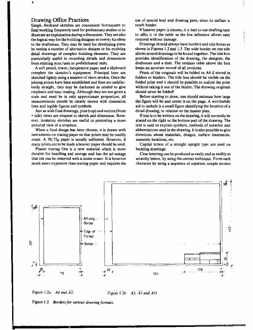
A0 841.x 1189mm Al 594 * 841mm A2 420 x 594mm A3 297 x 420mm A4 210 x 297mm
If the building plans tend to be very long, one of the following allvrnative sizes may be useful:
AI0 594 x Il89mm A20 420 x 1189mm A21 420 x 841mm A31 297 x 841mm A32 297 x 594mm
If possible, only one format should be used for all draw- ings in a project or alternatively all drawings should have the same height. The formats AO, A10 and A20 are difficult to handle and should therefore be avoided. One should instead try to use a smaller scale or divide the figure into more drawings.
Obviously a good drawing board, large enough to hold the size paper selected, is essential. One of the following sizes should be suitable:
A0 920 x 1270mm Al 650 x 920mm
While a sheet of hardboard or blockboard may be used as a drawing board, it is advisable to install a hardwood edge such as ebony. It may be necessary to saw longitudinal
i (I
\ L.
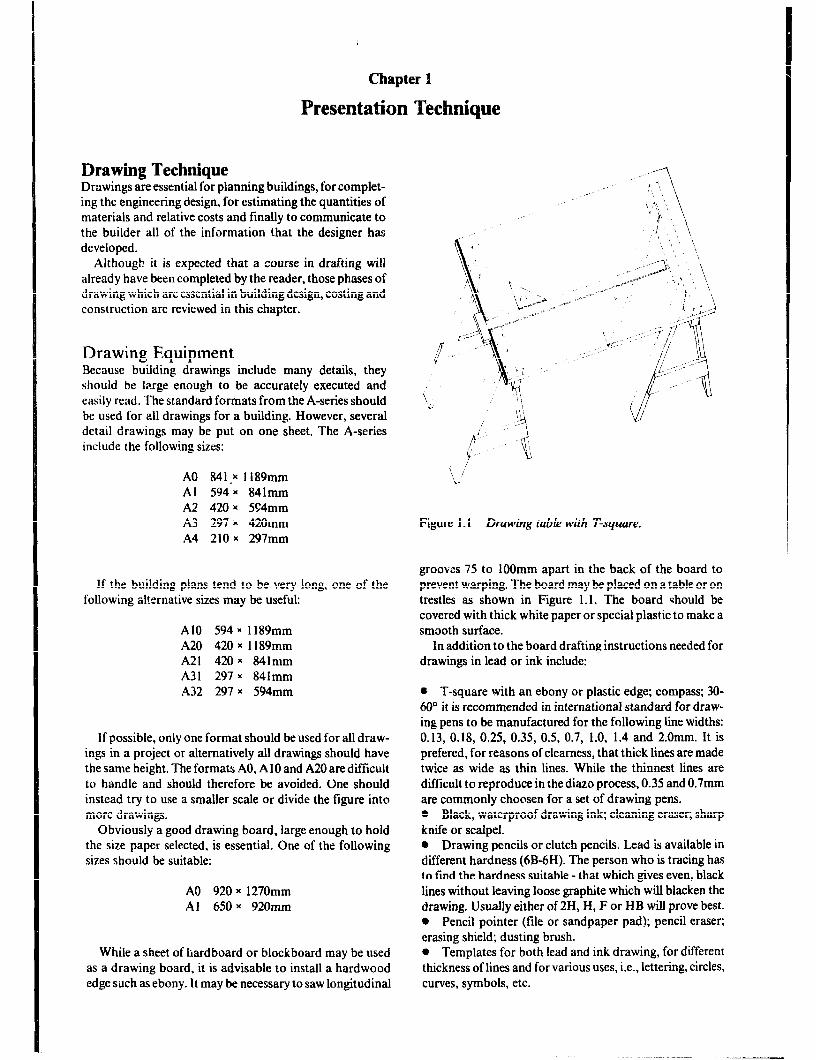
Figure 1. I Drawing table with T-square.
grooves 75 to 1OOmm apart in the back of the board to prevent warping. The board may be placed on a table or on trestles as shown in Figure 1.1. The board should be covered with thick white paper or special plastic to make a smooth surface.
In addition to the board drafting instructions needed for drawings in lead or ink include:
l T-square with an ebony or plastic edge; compass; 30- 60” it is recommended in international standard for draw- ing pens to be manufactured for the following line widths: 0.13, 0.18, 0.25, 0.35, 0.5, 0.7, 1.0, 1.4 and 2.0mm. It is prefered, for reasons of clearness, that thick lines are made twice as wide as thin lines. While the thinnest lines are difficult to reproduce in the diazo process, 0.35 and 0.7mm are commonly choosen for a set of drawing pens. l Black, waterproof drawing ink; cleaning eraser; sharp knife or scalpel. * Drawing pencils or clutch pencils. Lead is available in different hardness (6B-6H). The person who is tracing has to find the hardness suitable - that which gives even, black lines without leaving loose graphite which will blacken the drawing. Usually either of 2H, H, F or HB will prove best. 0 Pencil pointer (file or sandpaper pad); pencil eraser; erasing shield; dusting brush. 0 Templates for both lead and ink drawing, for different thickness of lines and for various uses, i.e., lettering, circles, curves, symbols, etc.
Drawing Office Practices Simple freehand sketches are convenient forerunners to final working frequently used for preliminary studies or to illustrate an explanation during a discussion. They are also the logical way for the building designer to convey his ideas to the draftsman. They may be used for developing plans by testing a number of ahemative designs or for evolving detail drawings of complex building elements. They are particularly useful in recording details and dimensions from existing structures or prefabricated units.
A soft pencil, eraz:er, inexpensive paper and a clipboard complete the sketcher’s equipment. Principal lines are sketched lightly using a number of short strokes. Once the joining points have been established and lines are satisfac- torily straight, they may be darkened as needed to give emphasis and easy reading. Although they are not given a scale and need be in only approximate proportion, all measurements should be clearly shown with dimension lines and legible figures and symbols.
Just as with final drawings, plan (top) and section (front + side) views are simplest to sketch and dimension. How- ever, isometric sketches are useful in presenting a more pictorial view of a structure.
When a final design has been chosen, it is drawn with instruments on tracing paper so that prints may be readily made. A 70175~ paper is usually sufficient. However, if many prints are to be made a heavier paper should be used.
Plastic tracing film is a new material which is more durable for handling and storage and has the advantage that ink can be removed with a moist eraser. It is however much more expensive than tracing paper and requires the
use of special lead and drawing pens, since its surface is, much harder.
W’hatever pa.per is chosen, it is best to use drafting tape to affix it to the table as the low adhesion allows easy removal without damage.
Drawings should always have borders and title boxes as shown in Figures 1.2 and 1.3. The wide border on one side allows several drawings to be bound together. The title box provides identification of the drawing, the designer, the draftsman and a date. The revision table above the box keeps an accurate record of all revisions.
Prints of the originals will be folded to A4 if stored in folders or binders. The title box should be visible on the folded print and it should be possible to unfold the print without taking it out of the binder. The drawing originals should never be folded!
Before starting to draw, one should estimate how large the figure will be and center it on the page. A worthwhile aid to include is a small figure identifying the location of a detail drawing, in relation to the master plan.
If text is to be written on the draw!.ng, it will normally be placed on the right or the bottom part of the drawing. The text is used to explain symbols, methods of notation and abbreviations used in the drawing. It is also possible to give directions about materials, designs, surface treatments, assembly locations, etc.
Capital letters of a straight upright type are used on building drawings:
Clear lettering can be produced as easily and as swiftly as scratchy letters, by using the correct technique. Form each character by using a sequence of separate, simple strokes
! Aff wtg -
@order
t
Edrp of -
Form
1
Border -
Figure 1.2a Ad and A-3. Figure 1.2b AZ. Al ond AO.
Figure 1.2 Borders for various drawing formats.

Presentation Technique 3
REV NOT REVISION REFER TO
Planning & Designing Company. Project Name or Clients Name
I Drawing Contents & Title.
DRAWN BY DESIGN aY CHECKED BY SCALE.
PLACE DATE SIGNATIJRE. JOB No DRAWING No REV
.26-- -..+ --5$-+ 2- 3 $ + ~~--~__ ------.--.~- $
Figure I .3 ZBlebox with revision table.
for the lines and bows. Use the least possible pressure and hold the pen upright and at 45’ angle to the line of writing.
Suggested heights for the letters are: 3mm for text in the figures, measurements and descriptive text; 5 and 7mm for headings and for drawings which are going to be reduced.
Lettering will normally run from left to right on the sheet and be parallel to the bottom edge. When it becomes necessary for lettering to NZ vertically, it should always run from the bottom upwards. (This applies also to strings of dimensions).
Horizontal guidelines are essential unless the draftsman is very experienced and skillful. They may be drawn lightly in pencil for subsequent erasure when the lettering is in ink or may take the form of a closely gridded sheet laid under- neath the tracing paper.
Letters and words are spaced by eye rather than by measuring. If the proportion, form and spacing of the letters is properly executed, the result will be legible and pleasing to the eye.
-ABCDEFGHI JKLMNOPQRS TWWXYZ 123 45678 9 10
CLEAR LETTERING CAN BE PROVUCEV AS EASlLY AND A5 SWIFTLY AS %RArCHY LETTER5 BY USING THE CDRREcT rE.CHNIQuES
Figure I .4 Lettering on building drawings.
L
The thickness of lines should be chosen so that the figures on the drawing are easy to read. The outer contour of the building and the walls between rooms should be thicker than equipment, fittings and measurements. The major outline will then be noted first and the details later.
The view should be chosen so that a minimum of hidden contours need be shown. Concealed contours and those in front of the cut are shown with broken or dotted lines, but should be included only when necessary to aid in the interpretation of the drawing.
It requires practice to draw lines of even thickness and blackness with lead. It is imperative to use a pencil with a sharp point. By rotating the pencil while drawing, the point will stay sharp longer. All lines should be drawn with the help of a ruler, except when sketching or drawing a perspective.
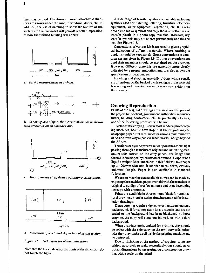
Dimensions are a very important part of the drawing and must be unequivocal and complete. No measurements should have to be calculated by the one who is using the drawing. Duplicate dimensions should be avoided since one may be forgotten if a change is made.
Dimensions should be easy to read and placed where the reader will expect to find them. They should appear 1 mm above the line and be placed so that they can be read either from the bottom or the right edge of the drawing. Dimen- sions should appear outside the figure if it does not make interpretation difficult. Related dimensions should be placed together, preferably in the same string. Dimensions may be given in a chain (See Figure 1.5a) or from a common point (Figure I .5c), the latter being used mainly when surveying existing buildings.
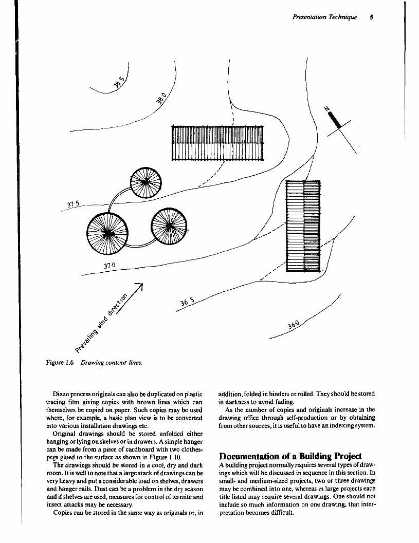
Contour lines on maps, site plans and master phms are drawn as unbroken lines to show the levels after the site work has been completed. The levels, as they were before the building activities started, are drawn with broken lines. Contour lines are not shown within structures. See Figure 1.6.
Sometimes outer walls and room-dividing walls are shaded with a pencil for emphasis. Alternatively, thicker
4
lines may be used. Elevations are more attractive if shad- ows are shown under the roof, in windows, doors, etc. In addition, the use of hatching to show the texture of the surfaces of the face-work will provide a better impression of how the finished building will appear.
b In case of lack of space the measurements can be shown with arrows or on an extended line.
c Measurements given from a common starting point.
7 I
l 620 1 25 .~ - >
I 1 I- ; +400.,
Plan l 620
;, 125
- , 1 LOO J7 -.--.-
Section
d Indication of levels and slopes in a plan and section.
Figure i.5 Techniques for giving dimensions,
Note that the lines indicating the limits of the dimension do not touch the figure.
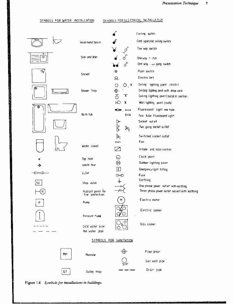
A wide range of transfer symbols is available including symbols used for hatching, lettering, furniture, electrical equipment, water equipment, vegetation, etc. It is also possible to make symbols and copy them on self-adhesive transfer plastic in a photo-copy machine. However, dry transfer symbols may not adhere permanently and thus be lost. See Figure 1.8.
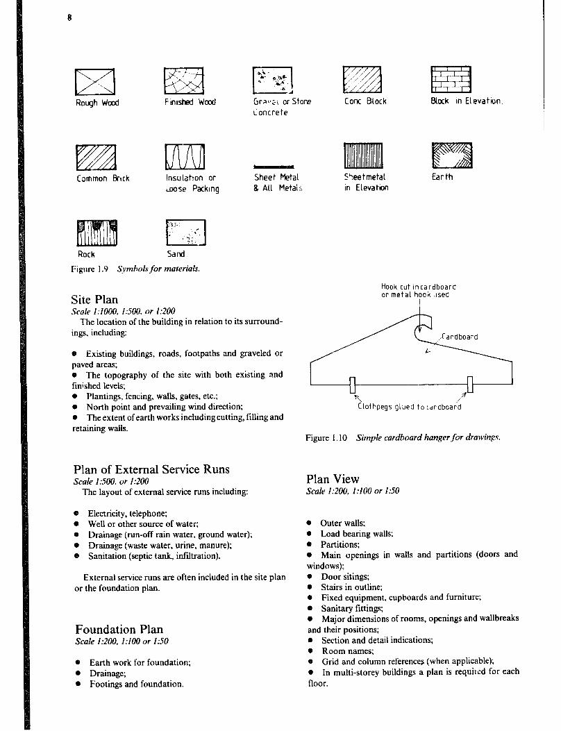
Conventions of various kinds are used to give a graphi- cal indication of different materials. Where hatching is used, it should be kept simple. Some conventions in com- mon use are given in Figure 1.9. If other conventions are used their meanings should be explained on the drawing. However, different materials are generally more clearly indicated by a proper annotation and this also allows the specification of qualities, etc.
Hatching and shading, especially if done with a pencil, are often done on the back of the drawing in order to avoid blackening and to make it easier to make any revisions on the drawing.
Drawing Reproduction Prints of the original drawings are always used to present the project to theclient, government authorities, manufac- turers, building contractors, etc. In practically all cases, one of the following processes will be used:
Electra-static copying, used in most modem photocopy- ing machines, has the advantage that the original may be on opaque paper. But most machines have a maximum size of A4 and even very expensive machines will not go beyond the A3-size.
The diazo or dyeline process relies upon ultra-violet light passing through a translucent original and activating diaz- onium salts carried on the copy paper. The image thus formed is developed by the action of ammoniavapour or a liquid develper. Most machines in this field will take paper up to 1200mm wide and, if supplied in roll form, virtually unlimited length. Paper is also available in standard A-formats.
Where no machines are available copies can be made by exposing the sensitized paper overlaid with the translucent original to sunlight for a few minutes and then developing the copy with ammonia.
Prints are available in three colours: black for architec- tural drawings, blue for design drawings and red for instal- lation drawings.
Diazo copying requires high contrast between lines and background. If for some reason lines drawn in lead are not sealed or the background has been blackened by loose graphite, the copy will come out blurred, or with a dark background.
When drawings are submitted for printing, they should be rolled with the side carrying the text outwards, other- wise they may make a roll inside the printing machine and be destroyed.
Due to shrinking or the method of copying, prints are seldom absolutely to scale. Accordingly, one should never obtain dimensions by measuring on a construction draw- ing, with a scale on the print!
Presentation Technique 5
Figure 1 A Drawing contour lines.
Diazo process originals can also be duplicated on plastic tracing film giving copies with brown lines which can themselves be copied on paper. Such copies may be used where, for example, a basic plan view is to be converted into various installation drawings etc.
Original drawings should be stored unfolded either hanging or lying on shelves or in drawers. A simple hanger can be made from a piece of cardboard with two clothes- pegs glued to the surface as shown in Figure 1.10.
The drawings should be stored in a cool, dry and dark room. It is well to note that a large stack of drawings can be very heavy and put a considerable load on shelves, drawers and hanger rails. Dust can be a problem in the dry season and if shelves are used, measures for control of termite and insect attacks may be necessary.
Copies can be stored in the same way as originals or, in
addition, folded in binden or rolled. They should be stored in darkness to avoid fading.
As the number of copies and originals increase in the drawing office through self-production or by obtaining from other sources, it is useful to have an indexing system.
Documentation of a Building Project A building project normally requires several types of draw- ings which will be discussed in sequence in this section. In small- and medium-sized projects, two or three drawings may be combined into one, whereas in large projects each title listed may require several drawings. One should not include so much information on one drawing, that inter- pretation becomes difficult.
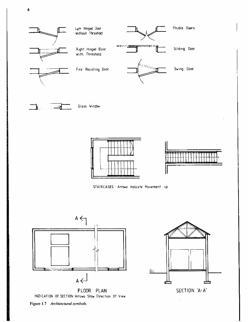
J1 Right Hmged Door ezce~=z~ 511dmg Door
With Threshold
Fire Reslstmg Door Swmg Door
STAIRCASES - Arrows Indicate Movement UP
FLOOR PLAN INDICATION OF SECTION-Arrows Sholr Dlrectlon Of View
Figure I .7 Architectural symbols.
SECTION 'A-A'
Presentation Technique 7
SYMBOLS FOR WATER INSTALLATION SYilBGLS FOR ELECTRICAL INSTALLATiuN
6 Ce~llrq switch
Cord opmbxi ceiling swikh
Two way switch
One way C’ +ch
Ihe way ,.J gang switch
Push switch
Electric bell
Celiq Lighting point i bulb I
Ceiling IigHng point with dmp cord
Celling lighting pnt (bulb) In section
Wall lighting pint (bulb)
Fluorescent light one tube
Two tube fluorescent Llgh t
Socket outlet
Two gang socket outlet
Switched socket outlet
Fan
In take and mom control
Clock point
Outdmr Llghhng point
Emergency light fitting
Fuse
Earthing
One phase power outlet withearthing
Three phase pwer wtlet socketwlth earthing
E lectr IC motor
Electr IC cooker
Wash hand basin
Sink and drier
Shower
Shower tray
Bath tub
b
lo2 k
Water closet
Tap hole
Waste hole
VUIW
5top valve
Hydrant point ior f Ire pmtection
Pump
t-o H
Pressure tank
Gas cooker Cold water pipe
Hot water pipe
SYMBOLS FOR SAN1 TATIm
cl
MH Manhole -@-
0 SVP
i-l ‘GT Gulley trap
-.-.-
Figure 1.8 Symbols for insrallation~ in buildings.
Floor drain
Soil vent pipe
Drain pipe
-Rough Wood Fwhed Wood Grw:i or Stone Concrete
Common &-lck insulahon or Loose Packing
Sheet Metal 8 ALL Metais
Rock sand
Figure I .9 Symbols for materials.
Site Plan Scale 1:IOOO. 1:XW. or 1:200
The location of the building in relation to its surround- ings, including:
+a Existing buildings, roads, footpaths and graveled or paved areas; 0 The topography of the site with both existing and finished levels; * Plantings. fencing, walls, gates, etc.; e North point and prevailing wind direction; 0 The extent of earth works including cutting, filling and retaining walls.
Plan of External Service Runs Scale 1:500, or I:200
The layout of external service runs including:
e Electricity, telephone; @ Well or other source of water; e Drainage (run-off ram water, ground water); 0 Drainage (waste water, urine, manure); o Sanitation (septic tank, infiltration).
External service runs are often included in the site plan or the foundation plan.
Foundation Plan Scale 1:200, 1:lOO or I:50
0 Earth work for foundation; @ Drainage; 0 Footings and foundation.
I , .//”
lizz2l ,’ ‘./ I I’ ,, ,/ ,i
Cone Block
S?eetmetal In Elevation
EUock In Elevation
Earth
Hook cut incardboard or metal hook [Ised
C‘lothpegs glued to cardboat;
Figure I. IO Simple cardboard hanger for drawings.
Plan View Scale 1:206. 1:lOO or 1.150
0 Outer walls; * Load bearing walls; 0 Partitions; 0 Main openings in walls and partitions (doors and windows); 0 Door sitings; 0 Stairs in outline: 0 Fixed equipment, cupboards and furniture; 0 Sanitary fittings; o Major dimensions of rooms, openings and wallbreaks and their positions; 0 Section and detail indications; * Room names; 0 Grid and column references (when applicable); 0 In multi-storey buildings a plan is required for each floor.
Presentation Technique 9
Section Scale 1:lOO or I.50
o Structural system for the building; 0 Major dimensions of height and levels and roof slopes; 0 Annotations on materials for walls. ceiling, roof and floor; 0 Foundation (if not in separate foundation plan).
Elevation Scale 1:200. I:100 or I.50
8 Doors; 0 Windows; 9 Miscellaneous external components; @ Shading and hatching for texture of facing surfaces (optional); o Dimensions of all projections from the building includ- ing roof overhangs.
Details Scale 1.20, l:lO, 1.5, 1:2 or I:I
The information that a builder needs to know for each element of the building he is to construct may be classified as follows:
Whar has to be installed or erected, including information about its nature and physical dimensions. Where it is to be placed, demanding graphic and dimen- sional information regarding its location. How it is to be placed or fixed in relation to adjacent elements.
The designer must include all details necessary for the builder to complete all elements of the building. When standard practice, general specifications or building codes are not followed, it is particularly important to include complete detail drawings. annotations and specifications.
Where prefabricated elements are used, for example windows, a specification rather than a detail drawing is adequate. This allows the builder to chose the least expen- sive alternative that meets the specification.
Where machinery and equipment require special foun- dations, supports, openings and cavities, the required detail drawings will, in most cases, be supplied by the manufacturer.
Often there is no need to produce detail drawings specifi- cally for each project. An established drawing office will have detail drawings covering the most frequent require- ments which may be affixed to current projects.
Plan of Electrical Installations Scale lr200, I:100 or 1:50
@ I
Incoming power supply and all wire locations; l
I
Main switch, fuses, meter; l Location of machinery and switches;
o Location of lighting points and switches, internal and external; @ Sockets; @ Annotations and dimensions.
Plan of Water and Simitizry Installations Scale 1:200, 1:lOO or 1.50
0 Pump, pressure tank, storage tank; 0 Water heater: l Water pipe locations; 0 Tapping points, valves and control equipment; l Waste water pipe location; 8 Waste water drains; sanitary installations; 0 Annotations, dimensions, levels, slopes.
List of Drawings Where there are several drawings for a building project loss or omission of a single drawings may be avoided by listing all of them on an A4 paper. Information on iatest revisions will ensure that all drawings are up to date.
Technical Spedcations The technical specifications should set out quality stand- ards for materials and workmanship in respect to building elements that have been described in the drawings. Where general specifications are available they are commonly referred to and only divergencies are specified in the tech- nical specifications.
However, in drawings for small- and medium-sized farm building projects, one tends to include much of the infor- mation normally given in the specifications, directly on the drawings.
As a basic rule, information should only be given once, either in the specifications, or on the drawing. Otherwise there is a risk that one place will be forgotten in a revision and thus cause confusion.
Functional and Manage,nent Instructions Frequently information has to be transferred to the person using a structure to enable him to utilise it in the most efficient way cr the way intended by the designer. In, a pig house, for example, different types of pens are intended for pigs of certain age intervals. Alleys and door swings may have been designed to facilitate handling of pigs during transfer between pens. In a grain’store the walls may have been designed to resist the pressure from grains stored in bulk to a specified depth.
10
Bill of Quantities The bill of quantities contains a list of all building materials requi;ed and is necessary to make a detailed cost estimate and a delivery plan. It can not be produced however, until the detailed working drawings and specifications have been completed.
Cost Estimate The client will require a cost estimate to determine whether the building should be constructed or not. He needs to know whether the proposed design is within his financial means and/ or whether the returns of the intended use of the building will justify the investment.
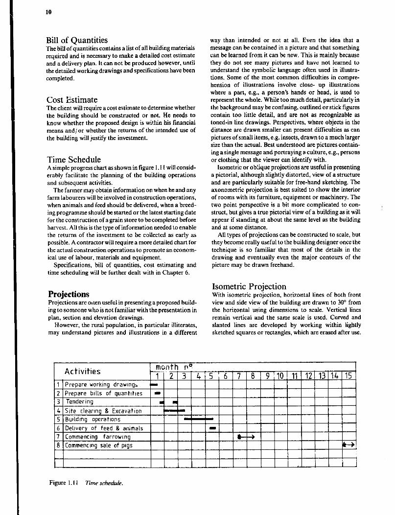
Time Schedule A simple progress chart as shown in figure 1.11 will consid- erably facilitate the planning of the building operations and subsequent activities.
The farmer may obtain information on when he and any farm labourers will be involved in construction operations, when animals and feed should be delivered, when a breed- ing programme should be started or the latest starting date for the construction of a gram store to be completed before harvest. All this is the type of information needed to enable the returns of the investment to be collected as early as possible. A contractor will require a more detailed chart for the actual construction operations to promote an econom- ical use of labour, materials and equipment.
Specifications, bill of quantities, cost estimating and time scheduling will be further dealt with in Chapter 6.
way than intended or not at all. Even the idea that a message can be contained in a picture and that something can be learned from it can be new. This is mainly because they do not see many pictures and have not learned to understand the symbolic language often used in illustra- tions. Some of the most common difficulties in compre- hension of illustrations involve close- up illustrations where a part, e.g., a person’s hands or head, is used to represent the whole. While too much detail, particularly in the background may be confusing, outlined or stick figures contain too little detail, and are not as recognizable as toned-in line drawings. Perspectives, where objects in the distance are drawn smaller can present difficulties as can pictures of small items, e.g. insects, drawn to a much larger size than the actual. Best understood are pictures contain- ing a single message and portraying a culture, e.g., persons or clothing :hat the viewer can identify with.
Isometric or oblique projections are useful in presenting a pictorial, although slightly distorted, view of a structure and are particularly suitable for free-hand sketching. The axonometric projection is best suited to show the interior of rooms with its furniture, equipment or machinery. The two point perspective is a bit more complicated to con- struct, but gives a true pictorial view of a building as it will appear if standing at about the same level as the building and at some distance.
All types of projections can be constructed to scale, but they become really useful to the building designer once the technique is so familiar that most of the details in the drawing and eventually even the major contours of the picture may be drawn freehand.
Projections Projections are otten useful in presenting a proposed build- ing to someone who is not familiar with the presentation in plan, section and elevation drawings.
However, the rural population, in particular illiterates, may understand pictures and illustrations in a different
Isometric Projection With isometric projection, horizontal lines of both front view and side view of the building are drawn to 30” from the horizontal using dimensions to scale. Vertical lines remain vertical and the same scale is used. Curved and slanted lines are developed by working within lightly sketched squares or rectangles, which are erased after use.
Figure 1.11 Time schedule.

Presentaticir Technique 11
Oblique Projection An oblique projection starts with a front view of the build- ing. The horizontal lines in the adjacent side are then draw to an angle, usually 30° or 45’, from the horizontal. The dimensions on the adjacent side are made equal to 0.8 of the full size if 30D is used or 0.5 if 45” is used. Curved and slanted lines are constructed in the same manner as in isometric projections.
Figure I. 12a Isometric
Figure 1.12b Oblique projections.
Figure I. I2
Axonometric Projection In axonometric projection the plan view of the building is placed on the drawing table with its side inclined from the horizontal dt any angle. Usually 30”, 45” or 60’ is chosen since those are the angles of the set squares. Ail vertical lines of the building remain vertical and are drawn to the scale of the plan view.
Figure I. 13 Axononretric projecrion.
Perspective The different technical terms used in perspective drawing can be explained if you imagine yourself standing in front of a window looking out at a building at some angle so that two sides of the building are visible. Trace on the window pane the outline of the building as you see it through the glass. You have then just made a perspective drawing of the building and if the glass could’be removed and laid on the drafting table the drawing would look like any perspective drawing made on paper.

12
Slalionpoint is the viewing point, supposedly occupied by the eye of the observer. The viewing point is also deter- mined by the eye level, usually assumed to be 1.7m above ground level. Looking across a large body of water or a plain. the sky and water/ground appears to meet in the distance - Ihe horizon line. This must always be considered present even when hidden by intervening objects. The horizon line is at eye level.
When standing and looking down a straight road, :he edges of the road appear to meet at a point-the vanishing point, which is on the horizon line and therefore also at eye level.
Similarly parallel horizontal lines of a building appear to meet at vanishing points, one for each visual side.
The outline of the building was broughl to the window by your vision - vision rays. The picture was traced on the window pane, which therefore can be calledpicrrrreplane.
Since the technique with a window pane obviously can not be used for a proposed but still non-existing building, the perspective hns to be canstructed from available docu- mentation. A perspective drawing of a building can be constructed using the plan view or, if several buildings are
’ to be included. the site plan would be more suitable. In addition one would require elevations of all visual sides of the building(s) i.e., in the case of one building the front elevation and one end elevation.
Construction of a Perspective
I Step 1 Locate a suitable station point (SP).
The distance between the station point and the object represents the true distance from the viewer to the building to the scale of the drawing. Accordingly, the longer the distance the smaller the building will appear in the picture.
Next draw a centre line of vision i.e., a line from the station point to the building. Fix the drawing on the drawing board with the centre line of vision (CLV) in a vertical position and cover with a transparent paper. Check that the building is falling within a 60’ cone of vision, since parts of it falling outside this cone will appear distorted when looking at the picture.
Step 2 Locate the picture plane (PP) and vanishing points (VP).
The picture plane is a line drawn at 90” to the centre of vision line i.e., horizontal on the drawing board The dis- tance between the station point and the picture plane will directly influence the size of the perspeaive picture. Think again of the situation where the outline of a building was traced on a window pane. If the window pane was moved closer, the outline picture would be smaller. Thus, if the reader of a perspective drawing is to get an image of the true size of the illustrated building, he will have to look at the perspective from the same distance as the distance between the station point and the picture plane when it was constructed. Therefore this distance is normally taken to be 400 to 600mm. The vanishing points are then located by drawing lines from the station point to the picture plane parallel to the visual sides of the building.
Step 3 Locate the horizon line (Hz) and the ground line
(GL). The horizon line can be located anywhere on the paper
as long as it is parallel to the picture plane, but leaving enough empty space to allow the perspective picture to be constructed around it. The ground line is then drawn paral- lel to the horizon line at a distance corresponding to the eye level to the scale of the drawing. The horizon !ine will always be above the ground line if the view point is above
Figure I. l4a Construction of a perspective drawing.

Presentation Technique 13
ground level. The vanishing points are then vertically transferred to the horizon line. It is helpful to put needles in thevanishing points on the horizon line to guide the ruler in further construction of the perspective.
Step J Locate a height line (HL) and mark the heights on this line.
True heights of the building can only be scaled on a height line in the perspective picture. Start by locating a height line on which heights concerning the front wall can be scaled. This is a vertical line from the point on the picture plane where it is crossed by a line extended from the front wall in the plan view. The point where the height line crosses the ground line will represent ground level and all heights in the front wall can now be scaled from this point to the scale of the plan view. Top and bottom lines for the front wall can now be drawn from the vanishing point through the marks on the height line.
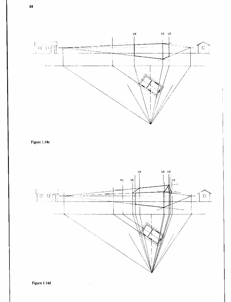
Step S Visual rays (VR) to locate points in the perspective view.
Visual rays are drawn to locate the exact position of the comers of the front wall in the perspective. The rays are drawn from the station point through the point to be located in the perspective to the picture plane. From the picture plane the line is continued vertically to the intersec- tion with the top and bottom lines. With further visual rays the outline of the visual walls can be drawn in the perspective.
Step 6 Further height lines and visual rays. To find the top line for a double pitched roof a new
height line must be constructed since that height is at a
plane behind that of the front wall. Visual rays are then used to find the ends of the ridge. Doors and windows in the front wall are constructed with the height line for the front wall and further visual rays to find points in the perspective.
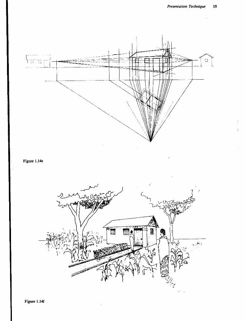
Step 7 Completing the perspective view. When the major outline of the building and principal
objects in the visual sides, such as doors and windows, have been constructed in the perspective view, the drawing tends to be quite crowded with tines. Further details are therefore usually more easily constructed freehand.
Finish the perspective by drawing vegetation and miscel- laneous objects which will appear in the surroundings of the building. People in the picture will always be drawn with their eyes on the horizon hne. The size will then determine the distance to the viewer. Finally cover the perspective drawing with tracing paper and redraw the picture leaving out all the construction lines.
Model Buildings Any person, including those who have had a good basic education, will need considerable experience to be able to visualise fully a building from a set of drawings. The farm building engineer will therefore soon learn that the average farmer not only finds it very difficult to understand simple plan view and section drawings, but may even find it hard to interpret fully rendered perspectives. However, the fact that a model, unlike drawings, is threedimensional and thud can be viewed from all sides brings more realism to the presentation and usually results in communication and transfer of ideas.
Figure 1.14b
14
Figure 1.14~
VR VR VR
-.
_-.. -._--
-.. -. ‘. ‘..
‘.. ‘, .‘\
Figure 1.M
Presentation Technique 15
.----- ----
Figure 1.14e
Figure 1.14f
16
There are three types of models in common use for presentation of farm building projects:
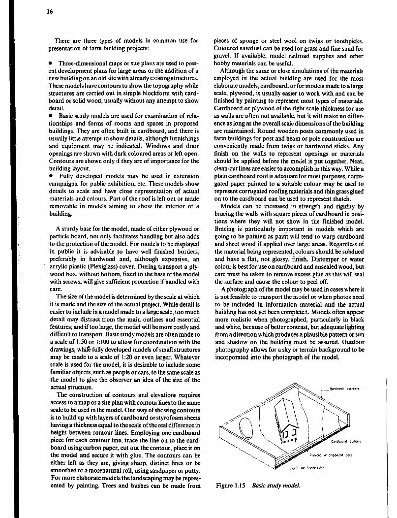
l Three-dimensional maps or site plans are used to pres- ent development plans for large areas or the addition of a new buirding on an old site with already existing structures. These models have contours to show the topography while structures are carried out in simple blockform with card- board or solid wood, usually without any attempt to show detail. l Basic study models are used for examination of rela- tionships and forms of rooms and spaces in proposed buildings. They are often built in cardboard, and there is usually little attempt to show details, although furnishings and equipment may be indicated. Windows and door openings are shown -with dark coloured areas or left open. Contours are shown only if they are of importance for the building layout. 0 Fully developed models may be used in extension campaigns, for public exhibition, etc. These models show details to scale and have close representation of actual materials and colours. Part of the roof is left out or made removable in models aiming to show the interior of a building.
A sturdy base for the model, made of either plywood or particle board, not only facilitates handling but also adds to the protection of the model. For models to be displayed in public it is advisable to have well finished borders, preferably in hardwood and, although expensive, an acrylic plastic (Plexiglass) cover. During transport a ply- wood box, without bottom, fixed to the base of the model with screws, will give sufficient protection if handled with care.
The size of the model is determined by the scale at which it is made and the size of the actual project. While detail is easier to include in a model made to a large scale, too much detail may distract from the main outlines and essential features; and-if too large, the model will be more costly and difficult to transport. Basic study models are often made to a scale of I:50 or 1: 100 to allow for coordination with the drawings, whil% fully developed models of small structures may be made to a scale of 1:20 or even larger. Whatever scale is used for the model, it is desirable to include some familiar objects, such as people or cars, to the same scale as the model to give the observer an idea of the size of the actual structure.
The construction of contours and elevations requires access to a map or a site plan with contour lines to the same scale to be used in the model. One way of showing contours is to build up with layers of cardboard or Styrofoam sheets having a thickness equal to the scale of the real difference in height between contour lines. Employing one cardboard piece for each contour line, trace the line on to the card- board using carbon paper, cut out the contour, place it on the model and secure it with glue. The contours can be either left as they are, giving sharp, distinct lines or be smoothed to a morenatural roll, using sandpaper or putty. For more elaborate models the landscaping may be repres- ented by painting. Trees and bushes can be made from
pieces of sponge or steel wool on twigs or toothpicks. Coloured sawdust can be used for grass and fine sand for gravel. If available, model railroad supplies and other hobby materials can be useful.
Although the same or close simulations of the materials employed in the actual building are used for the most elaborate models, cardboard, or for models made to a large scale, plywood, is usually easier to work with and can be finished by painting to represent most types of materials. Cardboard or plywood of the right scale thickness for use as walls are often not available, but it will make no differ- ence as long as the overall scak dimensions of the building are maintained. Round wooden posts commonly used in farm buildings for post and beam or pole construction are conveniently made from twigs or hardwood sticks. Any finish on the walls to represent openings or materials should be applied before the moliel is put together. Neat, clean-cut lines are easier to accomplish in this way. While a plain cardboard roof is adequate for most purposes, corru- gated paper painted to a suitable colour may be used to represent corrugated roofing materials and thin grass glued on to the cardboard can be used to represent thatch.
Models can be increased in strength and rigidity by bracing the walls with square pieces of cardboard in posi- tions where they will not show in the finished model. Bracing is particularly important in models which are going to be painted as paint will tend to warp cardboard and sheet wood if applied over large areas. Regardless of the material being represented, colours should be subdued and have a flat, not glossy, finish. Distemper or water colour is best for use on cardboard and unsealed wood, but care must be taken to remove excess glue as this will seal the surface and cause the colour to peel off.
A photograph of the model may be used in cases where it is not feasible to transport the model or when photos need to be included in information material and the actual building has not yet been completed. Models often appear more realistic when photographed, particularly in black and white, because of better contrast, but adequate lighting from a direction which produces a plausible pattern or sun and shadow on the building must be assured. Outdoor photography allows for a sky or terrain background to be incorporated into the photograph of the model.
Figure 1.15 Basic study model.

Presentation Technique 17
Further Reading Bellis H.F., Schmidt W.A., Architectural Drqfiing, New York, McGraw - Hill Book Co., 1971. McBean G., Kaggwa N. and Bugembe J., Illustrations for Development, Nairobi, Afrolit Society, 1980. Styles K., Working Drawings Handbook, London, Architectural Press, 1982. Taylor R., Model Buildingfor Architects and Engineers, New York, McGraw-Hill Book Co., 1971. V. Wmden J., de Keijzer M., Pforte W., Hohnerlein F., Rural Building- Drawing Book, Maastricht, Netherland, Stickting
Kongregatie F.I.C.
4
Chapter 2
Surveying
A simple survey of a building site provides accurate infor- mation needed to locate a building in relation to other structures or natural features. Dat, from the survey is then used for drawing a map of the site including contours and drainage lines if needed. Once located, the building foun- dation must be squared and leveled. This chapter will cover the several procedures involved.
Distances Steel tapes or surveyor’s chains are used for measuring distances when stations are far apart and the tape or chain must be dragged repeatedly. Linen or fiberglass tapes are more suitable for measuring shorter distances such as offsets when making a chain survey, or in laying out a foundation. To obtain accurate results a chaining crew must first practice tensioning the chain or tape so th2.t the tension will be equal on each measurement.
Range poles are 2 to 3 metre metal or wooden poles painted with red and white stripes, and used for sighting along the line to be measured.
Land arrows come in sets of 10 and are set out by the lead man in a chaining crew and picked up by the following man. The number picked up will be a check on the number of lengths chained. A field book is used in which to draw sketches and record measurements.
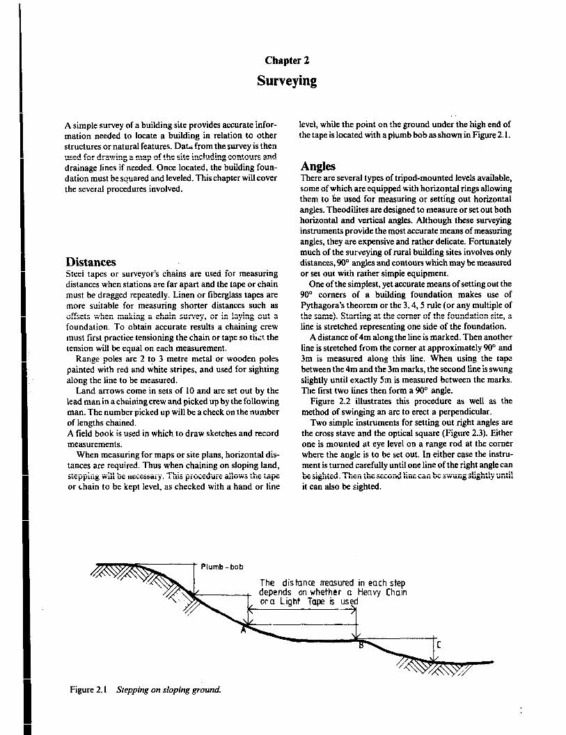
When measuring for maps or site plans, horizontal dis- tances are required. Thus when chaining on sloping land, stepping will be necessary. This procedure allows the tape or chain to be kept level, as checked with a hand or line
level, while the point on the ground under the high end of the tape is located with a plumb bob as shown in Figure 2.1.
Angles There are several types of tripod-mounted levels available, some of which are equipped with horizontal rings allowing them to be used for measuring or setting out horizontal angles. Theodilites are designed to measure or set out both horizontal and vertical angles. Although these surveying instruments provide the most accurate means of measuring angles, they are expensive and rather delicate. Fortunately much of the surveying of rural building sites involves only distances, 90” angles and contours which may be measured or set out with rather simple equipment.
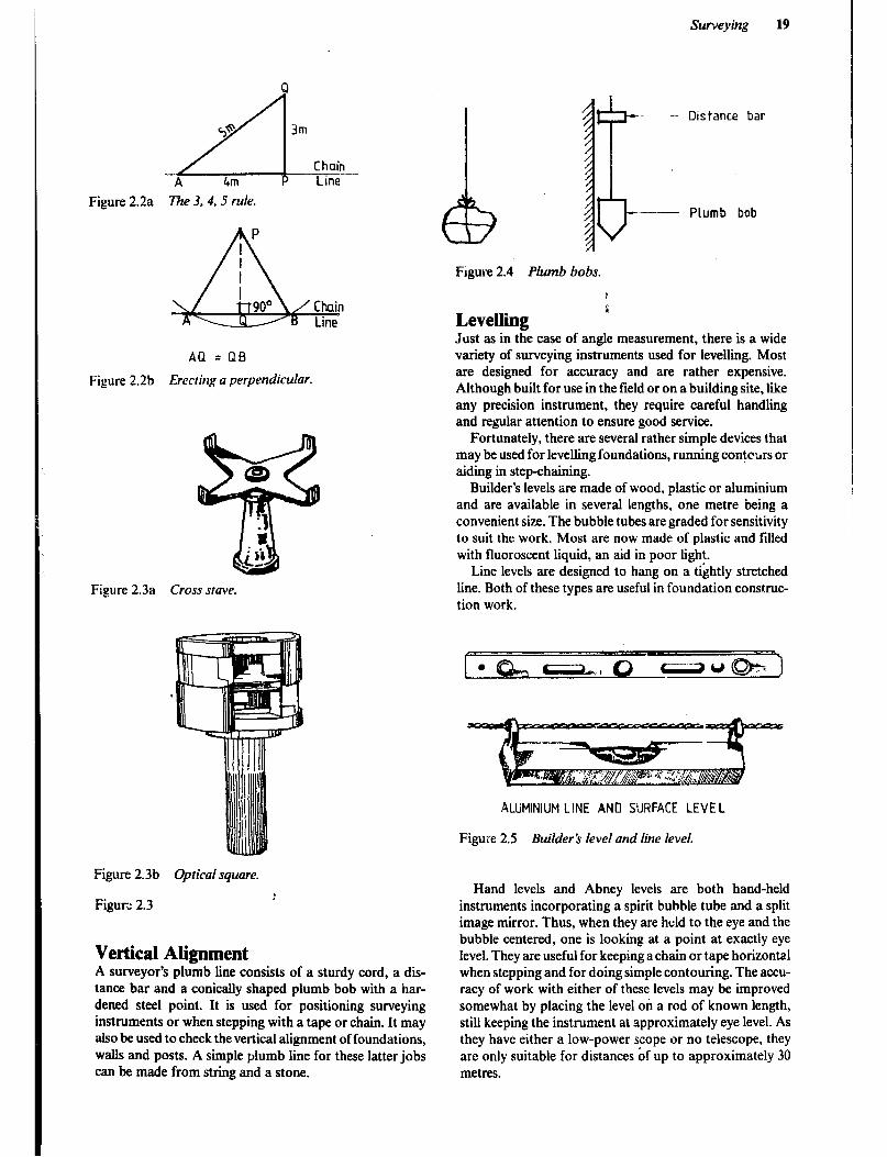
One of the simplest, yet accurate means of setting out the !JO” comers of a building foundation makes use of Pythagora’s theorem or the X4,5 rule (or any multiple of the same). Starting at the comer of the foundation site, a line is stretched representing one side of the foundation.
A distance of 4m along the line is marked. Then another line is stretched from the corner at approximately 90” and 3m is measured along this line. When using the tape between the 4m and the 3m marks, the second line is swung slightly until exactly 5m is measured between the marks. The first two lines then form a 90’ angle.
Figure 2.2 ilhrstrates this procedure as well as the method of swinging an arc to erect a perpendicular.
Two simple instruments for setting out right angles are the cross stave and the optical square (Figure 2.3). Either one is mounted at eye level on a range rod at the comer where the angle is to be set out. In either case the instru- ment is turned carefully until one line of the right angle can be sighted. Then the second line can be swung slightly until it can also be sighted.
Figure 2. I Stepping on sloping ground.
Surveyirtg 19
Figure 2.2a The 3, 4, 5 rule.
P
1 & I 9o" Chain Line
A[1 =QB
Figure 2.2b Erecting a perpendicular.
Figure 2.3a Cross save.
Figure 2.4 Plumb bobs.
Levellinpl L
Just as in tKe case of angle measurement, there is a wide variety of surveying instruments used for levelling. Most are designed for accuracy and are rather expensive. Although built for use in the field or on a building site, like any precision instrument, they require careful handling and regular attention to ensure good service.
Fortunately, there are several rather simple devices that may be used for levelling foundations, running contctirs or aiding in step-chaining.
Builder’s levels are made of wood, plastic or aluminium and are available in several lengths, one metre being a convenient size. The bubble tubes are graded for sensitivity to suit the work. Most are now made of plastic and filled with fluorescent liquid, an aid in poor light.
Line levels are designed to hang on a tightly stretched line. Both of these types are useful in foundation construc- tion work.
ALUM~NIUM LINE ANO SURFACE LEVEL
Figure 2.5 Builder h level and line level.
Figure 2.3b Optical square.
Figum 2.3 :
Vertical Alignment A surveyor’s plumb line consists of a sturdy cord, a dis- tance bar and a conically shaped plumb bob with a har- dened steel point. It is used for positioning surveying instruments or when stepping with a tape or chain. It may also be used to check the vertical alignment of foundations, walls and posts. A simple plumb line for these latter jobs can be made from string and a stone.
Hand levels and Abney levels are both hand-held instruments incorporating a spirit bubble tube and a split image mirror. Thus, when they are held to the eye and the bubble centered, one is looking at a point at exactly eye level. They are useful for keeping a chain or tape horizontal when stepping and for doing simple contouring. The accu- racy of work with either of these levels may be improved somewhat by placing the level on a rod of known length, still keeping the instrument at approximately eye level. As they have either a low-power scope or no telescope, they are only suitable for distances of up to approximately 30 metres.

20
For leveling the lines used in laying out a foundation, a builder’s water level is a simple, inexpensive device that provides a satisfactory degree of accuracy. It consists of a length of rubber or plastic tubing at each end of which there is a transparent sight tube of glass or plastic, It works well over adistance of about 30m and is particularly useful for transferring levels around comers, from outside a building to inside, or around obstacles where the two leveling points are not inter-visible. It is also a useful tool for obtaining the slope in pipe runs. Note Figure 2.6 for the method of use.
1 Set corner proJles at one corner as at right. 2 Place hose as shown. 3 Fill with water until water level is at top of corner profile “A ‘: 4 Mark water level at opposite end B and set profire to mark.
Figure 2.6 Setting out corner profiles.
Chain Surveying In a chain survey, the area to be surveyed is enclosed by one or more triangles -whose sides are measured and recorded. Then the perpendicular distance from the side of a triangle to each point of detail such as trees, buildings, boundaries, etc. is measured. From this information a detailed plan of the site can be drawn to scale. A proposed structure may then be superimposed on the plan and its location trans- ferred to the actual land site.
The following step-by-step procedure is used in a chain survey:
1 Make a preliminary survey by walking around the site, deciding where to put slations and where the main survey lines should be arranged. Stations should be selected so that they are intervisible and the lines laid out so that obstacles are avoided. Make a sketch of the site in the field book (Figure 2.7a). 2 Set the range poles, chain the triangle sides and record the distances. 3 Meas..re the perpendicular offsets from the chain lines to the details of the site. This will be easier to do ifthe chain lines have been arranged so that offsets can be kept as short as possible. Record the measurements in the field book (Figure 2.7b). Each page should record offsets along one chain line. Entries start from the bottom of the page and details are entered to the left or right of the center column where distances along the chain line are noted.
Not all details are measured by perpendicular offsets. Sometimes it is more accurate and convenient to use pairs of inclined offsets which together with a portion of the
chain form acute-angled triangles. Note the top comer of the house in Figure. 2.7b.
Figure 2.7a Field book sketch of the site with stations and main survey lines.
TO c 3j
\
TO B 65
/TOC 49
TO B 41
Figure 2.7b Field book recordings of offsets along chain line A-D.
4 If contour lines need to be included on the map or site plan, the next step will be to measure levels with a levelling instrument and a staff.
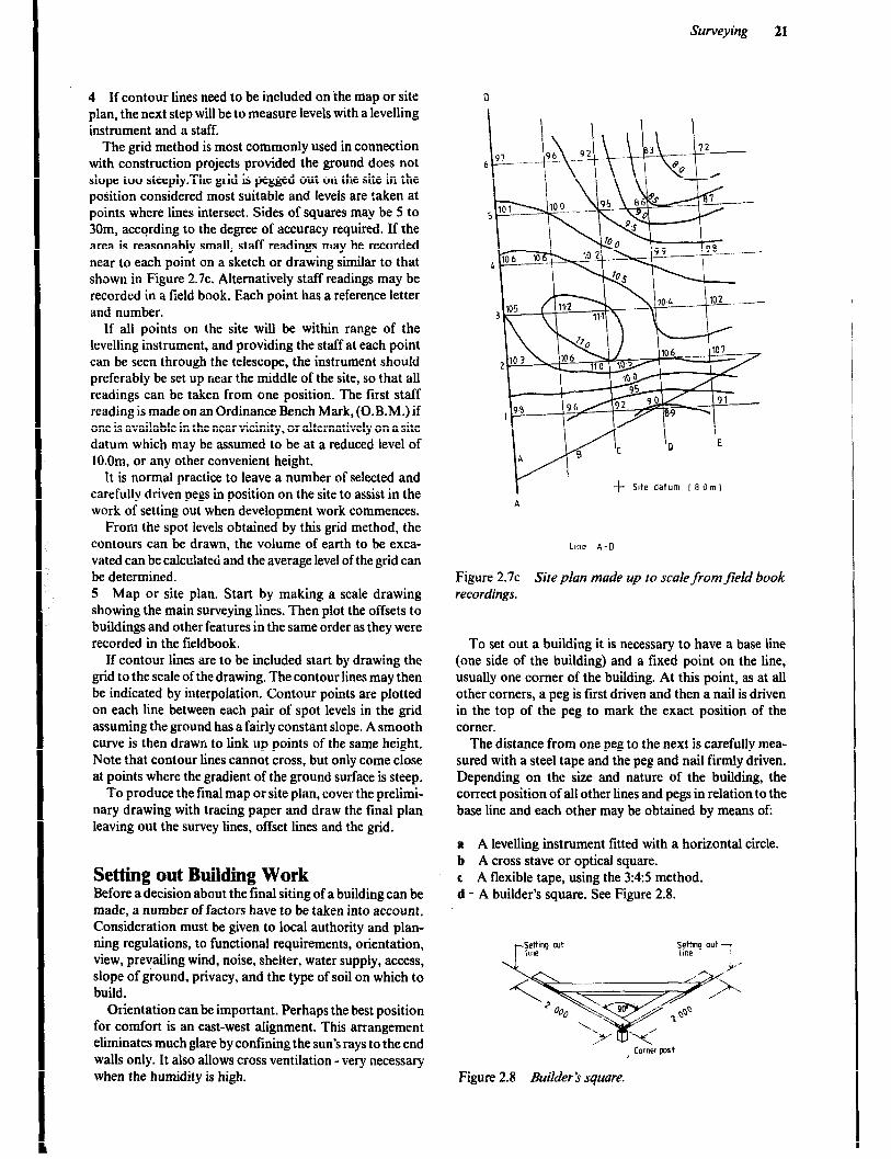
The grid method is most commonly used in connection with construction projects provided the ground does not slope too steeply.The grid is pegged out on the site in the position considered most suitable and levels are taken at points where lines intersect. Sides of squares may be 5 to 30m, according to the degree of accuracy required. If the area is reasonably small, staff readings may be recorded near to each point on a sketch or drawing similar to that shown in Figure 2.7~. Alternatively staff readings may be recorded in a field book. Each point has a reference letter and number.
If all points on the site will be within range of the levelling instrument, and providing the staff at each point can be seen through the telescope, the instrument should preferably be set up near the middle of the site, so that all readings can be taken from one position. The first staff reading is made on an Ordinance Bench Mark, (O.B.M.) if one is available in the near vicinity, or alternatively on a site datum which may be assumed to be at a reduced level of lO.Om. or any other convenient height.
It is normal practice to leave a number of selected and carefully driven pegs in position on the site to assist in the work of setting out when development work commences.
From the spot levels obtained by this grid method, the contours can be drawn, the volume of earth to be exca- vated can be calculated and the average level of the grid can be determined. 5 Map or site plan. Start by making a scale drawing showing the main surveying lines. Then plot the offsets to buildings and other features in the same order as they were recorded in the tieldbook.
If contour lines are to be included start by drawing the grid to the scale of the drawing. The contour lines may then be indicated by interpolation. Contour points are plotted on each line between each pair of spot levels in the grid assuming the ground has a fairly constant slope. A smooth curve is then drawn to link up points of the same height. Note that contour lines cannot cross, but only come close at points where the gradient of the ground surface is steep.
To produce the final map or site plan, cover the prelimi- nary drawing with tracing paper and draw the final plan leaving out the survey lines, offset lines and the grid.
Setting out Building Work Before a decision about the final siting of a building can be made, a number of factors have to be taken into account. Consideration must be given to local authority and plan- ning regulations, to functional requirements, orientation, view, prevailing wind, noise, shelter, water supply, access, slope of ground, privacy, and the type of soil on which to build.
Orientation can be important. Perhaps the best position for comfort is an east-west alignment. This arrangement eliminates much glare by confining the sun’s rays to the end walls only. It also allows cross ventilation - very necessary when the humidity is high.
Surveying 21
f Site datum ( 8 Om)
Line A-D
Figure 2.7~ Site plan made up to scale from field book recordings.
To set out a building it is necessary to have a base line (one side of the building) and a fixed point on the line, usually one corner of the building. At this point, as at all other corners, a peg is first driven and then a nail is driven in the top of the peg to mark the exact position of the corner.
The distance from one peg to the next is carefully mea- sured with a steel tape and the peg and nail firmly driven. Depending on the size and nature of the building, the correct position of all other lines and pegs in relation to the base line and each other may be obtained by means of:
a A levelling instrument fitted with a horizontal circle. b A cross stave or optical square. c A flexible tape, using the 3:4:5 method. d - A builder’s square. See Figure 2.8.
Figure 2.8 Builder’s square.
22
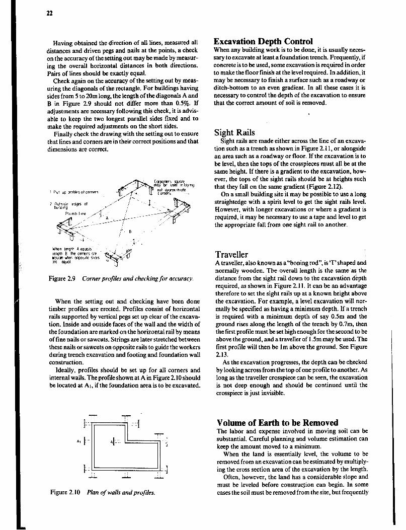
Having obtained the direction of all lines, measured all distances and driven pegs and nails at the points, a check on the accuracy of the setting out may be made by measur- ing the overall horizontal distances in both directions. Pairs of lines should be exactly equal.
Check again on the accuracy of the setting out by meas- uring the diagonals of the rectangle. For buildings having sides from 5 to 20m long, the length of the diagonals A and B in Figure 2.9 should not differ more than 0.5%. If adjustments are necessary following this check, it is advis- able to keep the two longest parallel sides fixed and to make the required adjustments on the short sides.
Finally check the drawing with the setting out to ensure that lines and corners are in their correct positions and that dimensions are correct.
Put up Finfksot corners
Figure 2.9 Corner profiles und checking for accuracy.
When the setting out and checking have been done timber profiles are erected. Profiles consist of horizontal rails supported by vertical pegs set up clear of the excava- tion. Inside and outside faces of the wall and the width of the foundation are marked on the horizontal rail by means of fine nails or sawcuts. Strings are later stretched between these nails or sawcuts on opposite rails to guide the workers during trench excavation and footing and foundation wall construction.
Ideally, profiles should be set up for all corners and internal walls. The profile shown at A in Figure 2.10 should be located at AI, if the foundation area is to be excavated.
Figure Plan of walls and profiles.
Excavation Depth Control When any building work is to be done, it is usually neces- sary to excavate at least a foundation trench. Frequently, if concrete is to be used, some excavation is required in order to make the floor finish at the level required. In addition, it may be necessary to finish a surface such as a roadway or ditch-bottom to an even gradient. In all these cases it is necessary to control the depth of the excavation to ensure that the correct amount of soil is removed.
Sight Rails Sight rails are made either across the line of an excava-
tion such as a trench as shown in Figure 2.11, or alongside an area such as a roadway or floor. If the excavation is to be level, then the tops of the crosspieces must all be at the same height. If there is a gradient to the excavation, how- ever, the tops of the sight rails should be at heights such that they fall on the same gradient (Figure 2.12).
On a small building site it may be possible to use a long straightedge with a spirit level to get the sight rails level. However, with longer excavations or where a gradient is required, it may be necessary to use a tape and level to get the appropriate fall from one sight rail to another.
Traveller A traveller, also known as a “boning rod”, is ‘T’shaped and normally wooden. The overall length is the same as the distance from the sight rail down to the excavation dkpth required, as shown in Figure 2.11. It can be an advantage therefore to set the sight rails up at a known height above the excavation. For example, a level excavation will nor- mally be specified as having a minimum depth. If a trench is required with a minimum depth of say OSm and the ground rises along the length of the trench by 0.7m, then the first profile must be set high enough for the second to be above the ground, and a traveller of 1 Sm may be used. The first profile will then be lm above the ground. See Figure 2.13.
As the excavation progresses, the depth can be checked by looking across from the top of one profile to another. As long as the traveller crosspiece can be seen, the excavation is not deep enough and should be continued until the crosspiece is just invisible.
Volume of Earth to be Removed The labor and expense involved in moving soil can be substantial. Careful planning and volume estimation can keep the amount moved t.o a minimum.
When the land is essentially level, the volume to be removed from an excavation can be estimated by multiply- ing the cross section area of the excavation by the length.
Often, however, the land has a considerable slope and must be leveled before construcJion can begin. In some cases the soil must be removed from the site, but frequently

Surveying 23
Traveller or boning
Figure 2.11 Sight rails and travellerfor boning.
7r \- \ , ,, Sight line
Figure 2.12 Section between 2 sight rails on a gradient.
bignr line
7
1 -r- - Traveller length
Minimum depth 0.5~ 11 I
Farmotion Line
Figure 2.13 Section showing level excavation.
24
what is removed from the building site can be use for fill in an adjacent area. Estimating how much to “cut”so the soil removed just equals the “fill” required to give a level site is somewhat more difficult. Several approaches are explained in surveying books, but a graphical method using the information from the site contour map should be satisfactory for rural building construction.
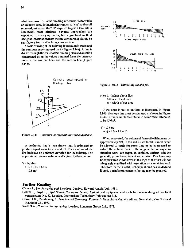
A scale drawing of the building foundation is made and the contours superimposed on it (Figure 2.14a). A line is drawn through the center of the building plan and a section constructed using the values obtained from the intersec- tions of the contour lines and the section line (Figure 2.14b).
I
\
Contours supertmposed on
Bullding plan
M
Figure 2.14a Contoursfor establishing a cut andfill line.
A horizontal line is then drawn that is estimated to produce equal areas for cut and fill. The elevation of the line indicates an optimum elevation for the building. The approximate volume to be moved is given by the equation:
V=Nhbw =HxO.O6x6x6 = 10.8 mz
11 5 SECTION M-N
110 Elevation - met rer 10 5
to 0
951 -
: : : ' : : : : ; 0123;56789
: :: 10 11 12
Buddmg length - metrer
20 UNEVEN SLOPE 1Om WIDE
15
10
IO5
0123 L5678 9 IO
Figure 2.14b, c Estimating cut andfill.
when h q height above line b = base of cut area w q width of cut area
If the slope is not as uniform as illustrated in Figure 2.14b, the slope line must be averaged as shown in Figure 2.14~. In this example the volume to be moved is estimated to be 45.6m*.
V=1/2hbw =‘/zx 1.9~4.8~ 10
When excavated, the volume of firm soil will increase by approximately 20%. If this soil is used for fill, it must either be allowed to settle for some time or be compacted to reduce the volume back to the original before any con- struction work can begin. In addition, African soils are generally prone to settlement and erosion. Problems may be experienced in wet areas at the edge of the till if it is not adequately stabilized with vegetation or a retaining wall. Therefore the ‘cut and fill’ technique should be avoided and if used, a reinforced concrete footing may be required.
Further Reading Clancy J., Site Surveying and Levelling, London, Edward Arnold Ltd., 198 1. Collett J., Boyd J., Eight Simple Surveying Levels, Agricultural equipment and tools for farmers designed for local
construction, No. 42, London, Intermediate Technology Publications Ltd. Olliver J.G., Clendinmng J., Principles ofsurveying, Volume 1: Plane Surveying, 4th edition, New York, Van Nostrand
Reinhold Co., 1979. Scott G.A., Construction Surveying, London, Longman Group Ltd., 1973.

Chapter 3
Building Materials
Building Materials A wide range of building materials is available for rural building construction. The proper selection of materials to be used in a particular building can influence the original cost, maintenance, ease of cleaning, durability and of course, appearance.
Several factors need to be considered in choosing the materials for a construction job, including:
1 Type and function of the building and the specific characteristics required of the materials used, i.e., great strength, water resistance, wear resistance, attractive appearance, etc. 2 Economic aspects of the building in terms of original investment and annual cost of maintenance. 3 Availability of materials in the area. 4 Availability of the skilled labour required to install some types of materials. 5 Quality and durability of different types of materials. 6 Transportation costs. 7 Selection of materials with properties, dimensions and means of installation that are compatible. 8 Cultural acceptability or personal preference.
Wood Wood is a commonly used building material in many parts of the world because of its reasonable cost, ease of working, attractive appearance and adequate life if protected from moisture and insects. However, forests are a valuable natu- ral resource that must be protected, particularly in areas with marginal rainfall. Thus, as good a material as wood is, there are regions where other materials should be consi- dered first simply on a conservation basis.
Wood for building is available from many different species with widely varying characteristics. Some species are used in the form of small poles for light construction while other species are aIlowed to mature so that timber (lumber in many countries) may be sawn from the large logs. The species that produce small inexpensive poles in rather short growing periods often grow in the fringes of agricultural land and can be used without danger to the ecology of the region.
The various species of wood have a number of physical characteristics that will be discussed in relation to the use of the wood in building construction.
Hardwoods vs Softwoods Wood cut from deciduous trees (those which drop their leaves sometime during the year) is spoken of as hardwood, while that cut from coniferous (needle bearing) trees is spoken of as softwood. Unfortunately, there is no relation-
ship as to whether the wood is actually soft or hard in this classification. In this book, hardwood respectively, soft- wood, will be used to classify wood with hard characteristics.
Wood Characteristics Strength in wood is its ability to resist breaking when it is used in beams and columns. Not only is strength related to the species, but also to moisture content and defects. Strength is also quite closely related to density.
Hardness is the resistance to denting and wear. Hard woods are more difficult to work but are required for tools, tool handles, flooring and other applications subject to wear, or where a high polish is desired.
Woods that are stiff resist deflection or bending when loaded. Stiff woods are not necessarily very strong. They may resist bending to a point and then break suddenly.
Tough woodF will deflect considerably before breaking. Even after fracturing, the fibres tend to hang together and resist separation. Tough woods are resistant to shock loading.
Warping is the twisting, bending, bowing distortions shown by some woods. The method of sawing and curing affects the amount of warping, but some species arc much more prone to warping than others.
Nail holding resistance for hard woods is greater than for softer woods. However, woods that are so hard that they are subject to spl.i:ting when nailed, lose much of their holding ability. Pre-boring to 75% of nail size avoids splitting.
The workability such as sawing, shaping and nailing is better for soft, low density woods than hard woods but they usually cannot be given a high polish.
Natural decay resistance is particularly important in the warm humid regions of East and Southeast Africa. There is a wide range of resistance shown by different species. However, for all species, heartwood (darker center area of the tree) is more resistant than the sapwood (lighter outer area of the tree). In addition to selection for natural decay resistance, wood preservatives should be considered where contact with the ground is likely.
Paint holding ability differs between woods, and as a rule this should be considered when selecting materials.
Defects in Wood Defects to watch for in selecting timber are:
Brittle hearr, found near the centre of many tropical trees, makes the wood break with a brittle fracture.
Wide growth rings indicate rapid growth resulting in thin-walled fibres with consequent loss of density and strength.
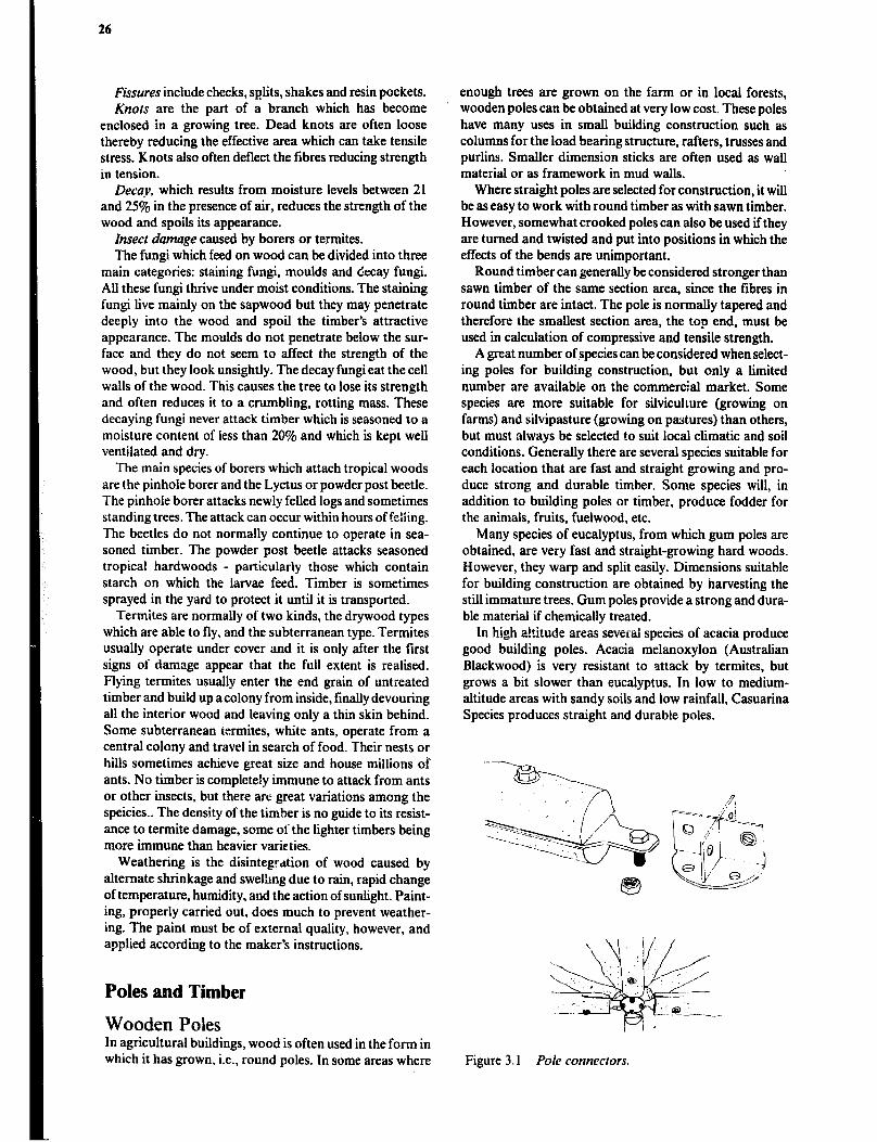
26
Fissures include checks, splits, shakes and resin pockets. Knots are the part of a branch which has become
enclosed in a growing tree. Dead knots are often loose thereby reducing the effective area which can take tensile stress. Knots also often deflect the fibres reducing strength in tension.
Decay, which results from moisture levels between 21 and 25% in the presence of air, reduces the strength of the wood and spoils its appearance.
Insect damage caused by borers or termites. The fungi which feed on wood can be divided into three
main categories: staining fungi, moulds and decay fungi. All these fungi thrive under moist conditions. The staining fungi live mainly on the sapwood but they may penetrate deeply into the wood and spoil the timber’s attractive appearance. The moulds do not penetrate below the sur- face and they do not seem to affect the strength of the wood, but they look unsightly. The decay fungi eat the cell walls of the wood. This causes the tree to lose its strength and often reduces it to a crumbling, rotting mass. These decaying fungi never attack timber which is seasoned to a moisture content of less than 20% and which is kept well ventilated and dry.
The main species of borers which attach tropical woods are the pinhole borer and the Lyctus or powder post beetle. The pinhole borer attacks newly felled logs and sometimes standing trees. The attack can occur within hours of f&iing. The beetles do not normally continue to operate in sea- soned timber. The powder post beetle attacks seasoned tropical hardwoods - particularly those which contain starch on which the larvae feed. Timber is sometimes sprayed in the yard to protect it until it is transported.
Termites are normally of two kinds, the drywood types which are able to fly, and the subterranean type. Termites usually operate under cover and it is only after the first signs of damage appear that the full extent is real&d. Flying termites usually enter the end grain of untreated timber and build up a colony from inside, finally devouring all the interior wood and leaving only a thin skin behind. Some subterranean termites, white ants, operate from a central colony and travel in search of food. Their nests or hills sometimes achieve great size and house millions of ants. No timber is completely immune to attack from ants or other insects, but there arc great variations among the speicies.. The density of the timber is no guide to its resist- ance to termite damage, some of the lighter timbers being more immune than heavier varieties.
Weathering is the disintegrdtion of wood caused by alternate shrinkage and swelhng due to rain, rapid change of temperature, humidity, and the action of sunlight. Paint- ing, properly carried out, does much to prevent weather- ing. The paint must be of external quality, however, and applied according to the maker’s instructions.
Poles and Timber
Wooden Poles In agricultural buildings, wood is often used in the form in which it has grown, i.e., round poles. In some areas where
enough trees are grown on the farm or in 104 forests, wooden poles can be obtained at very low cost. These poles have many uses in small building construction such as columns for the load bearing structure, rafters, trusses and purlins. Smaller dimension sticks are often used as wall material or as framework in mud walls.
Where straight poles are selected for construction, it will be as easy to work with round timber as with sawn timber. However, somewhat crooked poles can also be used ifthey are turned and twisted and put into positions in which the effects of the bends are unimportant.
Round timber can generally be considered stronger than sawn timber of the same section area, since the fibres in round timber are intact. The pole is normally tapered and therefore the smallest section area, the top end, must be used in calculation of compressive and tensile strength.
A great number of species can be considered when select- ing poles for building construction, but only a limited number are available on the commercial market. Some species are more suitable for silviculwre (growing on farms) and silvipasture (growing on pastures) than others, but must ‘always be selected to suit local climatic and soil conditions. Generally there are several species suitable for each location that are fast and straight growing and pro- duce strong and durable timber. Some species will, in addition to building poles or timber, produce fodder for the animals, fruits, fuelwood, etc.
Many species of eucalyptus, from which gum poles are obtained, are very fast and straight-growing hard woods. However, they warp and split easily. Dimensions suitable for building construction are obtained by harvesting the still immature trees. Gum poles provide a strong and dura- ble material if chemically treated.
In high a!titude areas several species of acacia produce good building poles. Acacia melanoxylon (Australian Blackwood) is very resistant to attack by termites, but grows a bit slower than eucalyptus. In low to medium- altitude areas with sandy soils and low rainfall, Casuarina Species produces straight and durable poles.
Figure 3,l Pole connectors.
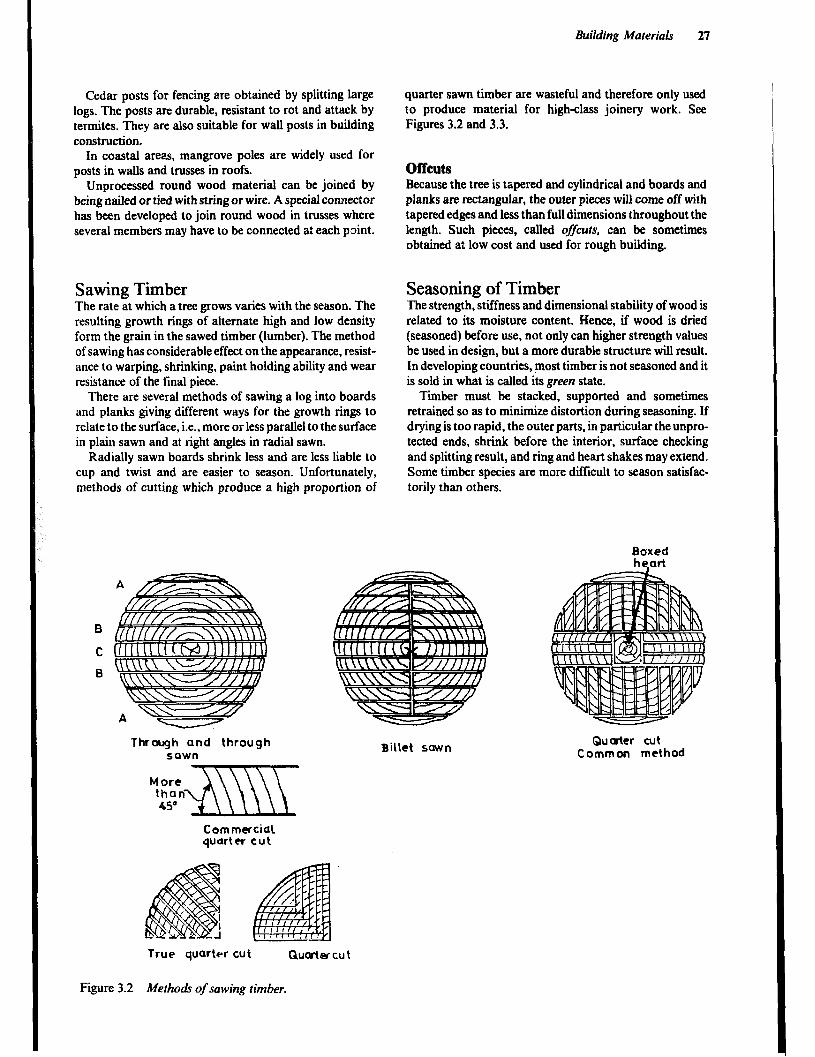
Building MateriaLr 21
Cedar posts for fencing are obtained by splitting large logs. The posts are durable, resistant to rot and attack by termites. They are also suitable for wall posts in building construction.
In coastal areas, mangrove poles are widely used for posts in wags and trusses in roofs.
Unprocessed round wood material can be joined by being nailed or tied with string or wire. A special connector has been developed to join round wood in trusses where several members may have to be connected a: each point.
Sawing Timber The rate at which a tree grows varies with the season. The resulting growth rings of alternate high and low density form the grain in the sawed timber (lumber). The method of sawing has considerable effect on the appearance, resist- ance to warping, shrinking, paint holding ability and wear resistance of the final piece.
There are several methods of sawing a log into boards and planks giving different ways for the growth rings to relate to the surface., i.e., more or less parallel to the surface in plain sawn and at right angles in radial sawn.
Radially sawn boards shrink less and are less liable to cup and twist and are easier to season. Unfortunately, methods of cutting which produce a high proportion of
Thrurgh and through sawn
Commercial quarter cut
quarter sawn timber are wasteful and therefore only used to produce material for high-class joinery work. See Figures 3.2 and 3.3.
offcuts
Because the tree is tapered and cylindrical and boards and planks are rectangular, the outer pieces will come off with tapered edges and less than full dimensions throughout the length. Such pieces, called offcurs, can be sometimes obtained at low cost and used for rough building.
Seasoning of Timber The strength, stiffness and dimensional stability of wood is related to its moisture content. Hence, if wood is dried (seasoned) before use, not only can higher strength values be used in design, but a more durable structure will result. In developing countries, most timber is not seasoned and it is sold in what is called its green state.
Timber must be stacked, supported and sometimes retrained so as to minimize distortion during seasoning. If drying is too rapid, the outer parts, in particular the unpro- tected ends, shrink before the interior, surface checking and splitting result, and ring and heart shakes may extend. Some timber species are more difficult to season satisfac- torily than others,
Billet sown Quwter cut
Common method
True quarter cut Qucstlsr cut
Figure 3.2 Methods of sawing timber.

28
LOW
GOOD
Bi?Sl
MEDIUM
Cupping of plain sawn boards caused by greater shortening of longer grwlh rings drying
Artificial Seasoning Artificial seasoning can be either moderate or rapid depending on the temperature of the air injected into the chamber where the timber is piled, and the rate at which the air is circulated and extracted from the chamber. Thii method is expensive and can only be applied on small quantities of timber. Timber can be artificially seasoned from the green condition, but often hot air seasoning is used only at a later stage after most of the moisture has been removed with air seasoning.
Smoke seasoning is a moderate process and involves placing the timber over a bonfire. It can take a month or two depending on the size and type of wood being sea- soned. This method is considered to be both a seasoning and a treating method for timber. Presumably it protects the timber against pest attacks and increases durability. However, it is not very reliable and can lead to splitting of the timber because of lack of control of the heat from the bonfire.
Care of Seasoned Timber Timber should be protected from moisture on the building site. Close piling and covering with tarpaulins delays the absorption of atmospheric moisture, particularly in the interior of the pile.
Timber Grade Standards and Sizes
Figure 3.3 Effects on Cupping and Shrinkage of difJerent methods of sawing.
Air Seasoning Timber should be protected from rain and from the ground and stacked so that air can circulate freely around all surfaces. Thus the risks of twisting and cupping and attack by fungi and insects are minimized. In favourable condi- tions, thin softwoods can be air seasoned in weeks but in unfavourable conditions some hardwoods require a year
Grades Grades are established by various government agencies. Even within one country more than one grading system may be in use. For small construction jobs, the grade may not be important, but in large projects where materials are bought by specification, it is important to indicate the grade standard being required.
Grades that provide specific information in structural design are most useful. For instance, the grade standard established by the Kenya Bureau of Standards illustrates this point in Table 3.1.
or more.
Table 3.1 Timber Grades and Applications
AR CURRENTS Grade Applications
F Furniture, high-class joinery GJ General joinery s 75 Structural grade, having a value of 75% of basic
. mess s 50 Struc:ural grade, having a value of 50% of basic
stress c A general construction grade for non-stressed
, I
L t-7 I 1 construction U IJ
1
L A low grade for lowquality work
It is the S 75 and S 50 grades that are significant in building
Figure 3.4 Air drying of timber. construction as will be seen in later sections.

Building Materials 29
Sizes Timber in East and Southeast Africa is available in a number of S.1. metric sizes, but not all are available in all localities. The dimension indicates actual size as sawn. Smoothing will reduce the timber to less than dimension size.
Timber Measurement for Trade Timber is normally sold in metre (or foot) running length; however, the price may be calculated per cubic metre when sold in large quantities. Basic lengths are from 1.8 to 6.3m although pieces more than about 5.lm are scarce and costly. Timber normally comes in running lengths, that is, not sorted for length.
Strength of Wobd Building materials of any type which are loaded are said to be subjected to afibre stress. The safefibre stress for a material is rhe load which the material will safely resist. Wood, like other materials has safe tibre stress values given in N/mm* which have been determined by destructive testing to get first an ultimate stress, and then, by the use of various correction and safety factors, safe fibre stresses to use in designing.
Table 3.2 lists basic wdrking stress values for several types of loading in 5 strength groups. Table 3.3 divides some representative species into the strength groups to be used in Table 3.2.
There are dozens of additional species of trees found in East Africa many of which are used only in very local areas. In order to obtain approximate working stress data for these indigenous species, their densities may be used to place them in the proper group for Table 3.2. If the density is not known, a good approximation can be found quite
easily. A bucket, a graduated cylinder (millilitres) and an accurate scale for weighing a sample of the wood will be needed. The procedure is:
1 weigh the sample, 2 place bucket on a level surface and fill to rim with water, 3 carefully submerpe sample and then remove, 4 refill bucket from graduated cylinder, noting the amount of water needed to refill the bucket. 5 Density = weight/volume = kg/ m3 6 Place species in appropriate group using appropriate density column for a green or dry sample. See Table 3.2, column 3 or 4.
Table 3.2 lists basic working stress values. For design purposes these should be adjusted for a number of different variables including: grade, moisture content, duration of load, exposure, and use of the structure.
Grades According to Kenya Forest Department the grades should be used as follows
Grade 1 Grade 2 Grade 3 Grade 4
Use 75% of basic working stress value 50% of basic working stress value 35% of basic working stress value 15% of basic working stress value
Moisture Table values need to be reduced when timber is installed green and will re,-lain wet and uncured continuously. Use Figure 3.5 to find a suitable stress value for green wood corresponding to the dry value in Table 3.2.
Table 3.2 Guide to Basic Working Stresses Values and Module of Elasticity for Timber
Maximum compression Max. shearing
Max. bending strength strength Strength Strength Density Density strength and Modulus of
group rating green 12% M.C. tension 11 to grain elasticity 11 to grain I to grain Beams Joints
kg/m’ kg/ mJ N/mm’ kN/mm? N/mm” N/mm2 N/mm’ B/mm2 - I Weak < 520 <400 IO 4.0 2.5 0.6 1.0 0.4
2 Fairly strong 521-650 401-500 I5 6.0 10.0 I.2 1.3 1.6
3 Strong p51-830 501-640 20 1.5 13.0 2.0 1.9 2.4 . _.-. - . .
4 Very strong 83l-Ku0 641-800 30 9.0 20.0 3.2 2.4 3.5
5 Exceptionally strong > IO41 > x01 50 IO.5 29.0 5.0 3.2 4.1

30
200 400 600 + a0 iOQ0
Kg/Id - 12 % m.c
2r, ( 400 600 BOO 1000
- l?O/, mr
7TI,ENGTH GR'UPS
Figure 3.5 &a& working stresses for timber.

Building Materials 31
Table 3.3 Some Representative Timbers Grouped According to Strength and Density
Group Latin Name Common Name
r Pinus radiata 12yr Young pine
Polyscias kikuyuensis Mutati
2 Cordia abyssinica Muringa
Piiius patula (17yr)* Pine
Pinus radiata (17yr) Pine
Cupressus lusitaniza** East African Cypress
Podocarpus Podo! Musengera
Juniperus procera African Pencil Cedar/ Mutarakwa
Ocrea usambarensis East African Camphorwoodi Muzaiti
Acacia melanoxylon Australian Blackwood
Grevillia robusta Grevillia/ Silky Oak
Vitex keniensis* Vitexi Muhuru/ Meru Oak
Prerocarpus angolensis Muninpa
Khay anthotheca African Mahogany
Eucalyptus regnans Australian Mountain Ash
4 cassipourea malosana Pillarwood/ Musaisi
Dombeya goetsenii Mueko
Eucalyptus saligna Saligna gum/ Sydney blue gum
PJCmna maxima’ -
Afzelia quanensis Afzelia
5 Olea hochstetteri East African Olive/ Musharagi
* one group lower in compression perpendicular to grain
** one group lower in joint shear
Exposure Timbers exposed to severe weather and decay hazards should be designed using a 25% stress value decrease, particularly for columns and for bearing points.
Timber Preservation The main structural softwood timbers of East and Southeast Africa are not naturally durable. If used in conditions subject to fungal, insect or termite attack, they will fail after some time. To avoid this, the timber used in permanent structures should be treated with a preservative.
Effective preservation depends on the preservative and how it is applied An effective preservative should be poisonous to fungi and insects, permanent, able to pene- trate sufficiently, cheap and readiiy available. It should not corrode metal fastenings, nor should the timber be ren- dered more flammable by its use. It is sometimes desirable to have a preservative-treated surface which can be painted.
If a structure is correctly designed and built, and the moisture content of its tir,ber does not exceed 20%, then a preservative treatment ir generally unnecessary as protec- tion against fungal attack. Where the above conditions are not present, however, there will bc a risk of fungal decay, and proper preservation is recommended.
Wood Preservatives Creosote is an effective general purpose preservative, cheap and widely used for exterior work and to a lesser degree inside. It is a black to brownish oil produced by the distillation of coal-tar, and has many of the properties required of a preservative, but it increases flammability, is subject to evaporation, and creosoted wood cannot be painted. It should not be used on interiors if the character- istic smell would be objectionable. Unfortunately creosote has been found to be a carcinogen and must be used with caution.
Coal-tar as a preservative is not as effective as the creo- sote produced from it. Tar is less poisonous, it does not penetrate the timber because of its viscosity, it is blacker than creosote and it is unsuitable for interior wood work.
Unleachable metallic salts are mostly based on copper salts. A combination of copper/chrome/arsenate is used. The copper and arsenical salt are the toxic preservatives which are rendered nonleaching (cannot be washed out) by the chrome salt acting as a fixing agent. The timber is impregnated by a “vacuum-pressure” process. Preserva- tion by metallic salt is being increasingly used since the treated surfaces are odourless and can be painted or glued.
Water-soluable preservatives are not satisfactory for exterior use, as they are liable to be removed from the timber by rain. They are, however, very suitable for interior work, as they are comparatively odourless and colourless, and the timber can bc painted.
Used engine oil can often, at least in small quantities, be obtained free of charge. The oil contains many residual products from combustion and some of them will act as preservatives, but it is not nearly as effective as commercial preservatives. It can be thinned with diesel fuel for better penetration. The combination of 401 of used engine oil and II of Dieldrin is a viable alternative in rural construction.
Methods of Wood Preservation To be effective preservation three main methods of preservation:
1 Pressure impregnation of timber placed in a horizontal steel cylinder is one of the best ways to apply preservatives into the wood. Creosote is the main preservative used, but unleachable metallic salts are also commonly applied by this method. Water-borne preservatives must be applied with the pressure treatment if the timber will be exposed to rain or ground moisture. Surface-applied water-borne prc- servatives quickly leach away leaving the timber unprotected. 2 Open tank treatment, known as steeping or soaking is used for relatively small quantities of timber.
a Hot and cold steeping. The tank with the preservative and timber is heated to nearly boiling, held for one to two hours and then allowed to coel. During the heating period the cells and the air in the cells expand and some of the air is expelled. As the timber and preservative cool the timber
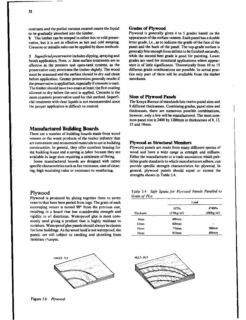
32
contracts and the partial vacuum created causes the liquid to be gradually absorbed into the timber. b The timber can be steeped in either hot or cold preser- vative, but it is not as effective as hot and cold steeping. Creosote or metallic salts can be applied by these methods.
3 Superjicialpreservolhn includes dipping, spraying and brush application. None ai :hese surface treatments are as effective as the pressure and open-tank systems, as the preservative only penetrates the timber slightly. The wood must be seasoned and the surface should be dry and clean before application. Greater penetration generally results if the preservative is applied hot, especially if creosote is used. The timber should have two coats at least; the first coating allowed to dry before the next is applied. Creosote is the most common preservative used for this method. Supefi- cial treatment with clear liquids is not recommended since the proper application is difficult to control.
Manufactured Building Boards T’here are a number of building boards made from wood veneers or the waste products of the timber industry that are convenient and economical materials to use in building construction. In general, they offer excellent bracing for the building frame and a saving in labor because they are available in large sizes requiring a minimum of fitting.
Some manufactured boards are designed with rather specific characteristics such as fire resistance, ease of clean- ing, high insulating value or resistance to weathering.
Plywood Plywood is produced by gluing together three to seven veneers that have been peeled from logs. The grain of each succeeding veneer is turned 90° from the previous one, resulting in a board that has considerable strength and rigidity in a!1 directions. Waterproof glue is most com- monly used giving a product that is highly resistant to moisture. Waterproof glue panels should always be chosen for farm buildings. As the wood itself is not waterproof, the panels, are still subject to swelling and shrinking from moisture thanges.
Grades of Plywood Plywood is generally given 4 to 5 grades based on the appearance of the surface veneers. Each panel has adouble letter grade, i.e., as to indicate the grade of the face of the panel and the back of the panel. The top-grade surface is generally free enough from defects to be finished naturally, while the second-best grade is good for painting. Lower grades are used for structural applications where appear- ance is of little significance. Theoretically from 10 to 15 different grade combinations are possible. In actual prac- tice only part of them will be available from the timber merchants.
Sizes of Plywood Panels ’ The Kenya Bureau of standards lists twelve pan@ sizes and 9 different thicknesses. Combining grades, panel sizes and thicknesses, there are numerous possible combinations, however, only a few will be manufactured. The most com- mon panel size is 2400 by 12OOmm in thicknesses of 9,12, 15 and 19mm.
Plywood as Structural Members Plywood panels are made from many different species of wood and have a wide range in strength and stiffness. Either the manufacturer or a trade association which pub- lishes grade standards to which manufacturers adhere, can provide specific strength characteristics for plywood. In general, plywood panels should equal or exceed the strengths shown in Table 3.4.
Table 3.4 Safe Spans for Plywood Panels Paralled to Grain q” Plys
Load
Thickness
Ymm
12mm
15mm
19mm
167Pa
(170kg!mz)
400mm
600mm
770mm
925mm
4790Pa
(49Okgi rn?
-
300mm
400mm
Figure 3.6 Plywood.
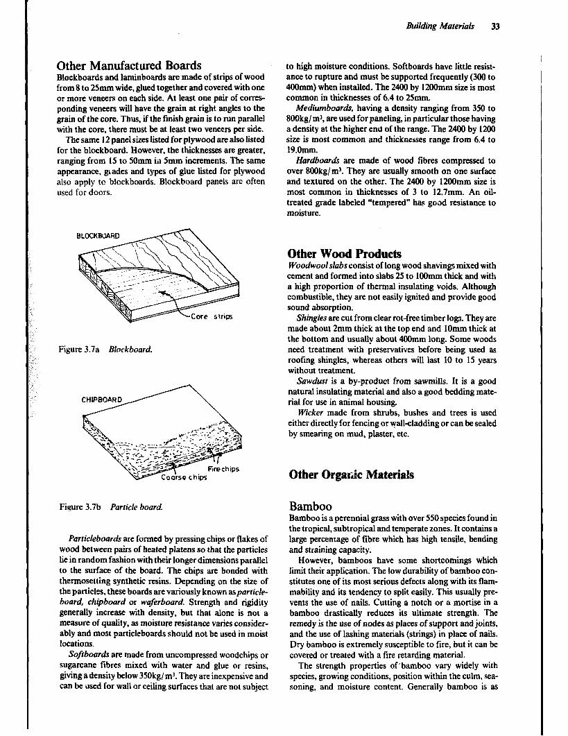
Building Materials 33
Other Manufactured Boards Blockboards and laminboards are made of strips of wood from 8 to 25mm wide, glued together and covered with one or more veneers on each side. At least one pair of corres- ponding veneers will have the grain at right angles to the grain of the core. Thus, if the finish gram is to run parallel with the core, there must be at least two veneers per side.
The same 12 panel sizes listed for plywood are also listed for the blockboard. However, the thicknesses are greater, ranging from 15 to 50mm ii1 5mm increments. The same appearance, gt,ades and types of glue listed for plywood also apply to blockboards. Blockboard panels are often used for doors.
to high moisture conditions. Softboards have little resist- ance to rupture and must be supported frequently (300 to 400mm) when installed. The 2400 by 12OOmm size is most common in thicknesses of 6.4 to 25mm.
Mediumboards, having a density ranging from 350 to 8OOkg/ mr, are used for paneling, in particular those having a density at the higher end of the range. The 2400 by 1200 size is most common and thicknesses range from 6.4 to 19.0mm.
Hardboards are made of wood fibres compressed to over 8OOkg/m’. They are usually smooth on one surface and textured on the other. The 2400 by 12OOmm size is most common in thicknesses of 3 to 12.7mm. An oil- treated grade labeled “tempered” has good resistance to moisture.
Other Wood Products Woodwoolslabs consist of long wood shavings mixed with cement and formed into slabs 25 to 1OOmm thick and with a high proportion of thermal insulating voids. Although combustible, they are not easily ignited and provide good sound absorption.
Figure 3.7a Blockboard.
Shingles are cut from clear rot-free timber 108s. They are made about 2mm thick at the top end and 1Omm thick at the bottom and usually about 400mm long. Some woods need treatment with preservatives before being used as rooting shingles, whereas others will last 10 to 15 years without treatment.
Sawdust is a by-product from sawmills. It is a good natural insulating material and also a good bedding mate- rial for use in animal housing.
Wicker made from shrubs, bushes and trees is used either directly for fencing or v+ll-cladding or can be sealed by smearing on mud, plaster, etc.
Other Orgaric Materials
Figure 3.7b Particle board. Bamboo
Particleboards are formed by pressing chips or flakes of wood between pairs of heated platens so that the particles lie in random fashion with their longer dimensions parallel to the surface of the board. The chips are bonded with thermosetting synthetic resins. Depending on the size of the particles, these boards are variously known asparticle- board, chipboard or waferboard. Strength and rigidity generally increase with density, but that alone is not a measure of quality, as moisture resistance varies consider- ably and most particleboards should not be used in moist locations.
Softboards are made from uncompressed woodchips or sugarcane fibres mixed with water and glue or resins, giving a density below 3SOkg/ m3. They are inexpensive and can be used for wall or ceiling surfaces that are not subject
Bamboo is a perennial grass with over 550 species found in the tropical, subtropical and temperate zones. It contains a large percentage of fibre which has high tensile, bending and straining capacity.
However, bamboos have some shortcomings which limit their application. The low durability of bamboo con- stitutes one of its most serious defects along with its flam- mability and its tendency to split easily. This usually pre- vents the use of nails. Cutting a notch or a mortise in a bamboo drastically reduces its ultimate strength. The remedy is the use of nodes as places of support and joints, and the use of lashing materials (strings) in place of nails. Dry bamboo is extremely susceptible to fire, but it can be covered or treated with a fire retarding material.
The strength properties of’bamboo vary widely with species, growing conditions, position within the culm, sea- soning, and moisture content. Generally bamboo is as
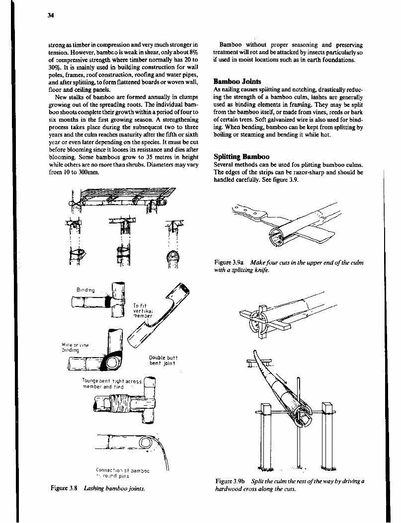
34
strong as timber in compression and very much stronger in tension. However, bambco is weak in shear, only about 8% of compressive strength where timber normally has 20 to 30%. It is mainly used in building construction for wall poles, frames, roof construction, roofing and water pipes, and after splitting, to form flattened boards or woven wall, floor and ceiling panels.
New stalks of bamboo are formed annually in clumps growing out of the spreading roots. The individual bam- boo shoots complete their growth within a period of four to six months in the first growing season. A strengthening process takes place during the subsequent two to three years and the CU~TI reaches maturity after the fifth or sixth year or even later depending on the species. It must be cut before blooming since it looses its resistance and dies after blooming. Some bamboos grow to 35 metres in height while others are no more than shrubs. Diameters may vary from 10 to 300mm.
Wtreorvine
Double butt bent joint
Toungebent tqhtacross member-and tied
Connectionof bamboo \\ -* round pins
Figure 3.8 Lashing bamboo joints.
Bamboo without proper seasoning and preserving treatment will rot and be attacked by insects particularly so if used in moist locations such as in earth foundations.
Bamboo Joints As nailing causes splitting and notching, drastically reduc- ing the strength of a bamboo culm, lashes are generally used as binding elements in framing. They may be split from the bamboo itself, or made from vines, reeds or bark of certain trees. Soft galvanized wire is also used for bmd- ing. When bending, bamboo can be kept from splitting by boiling or steaming and bending it while hot.
Splitting Bamboo Several methods can be used fos plitting bamboo culms. The edges of the strips can be razor-sharp and should be handled carefully. See figure 3.9.
Figure 3.9a Make four cuts in the upper end of the culm with a splitting knife.
Figure 3.9b Split the culm the rest of the wa)t by driving a hardwood cross along the cuts.
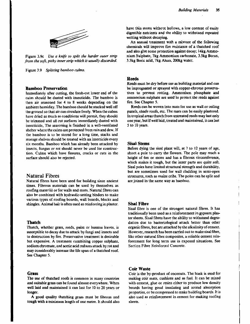
Building Materials 35
Figure 3.9~ Use a knve to split the harder outer strip from the soft, pithy inner strip which is usually discarded.
Figure 3.9 Splitting bamboo culms.
Bamboo Preservation Immediately after cutting, the fresh-cut lower end of the culm should be dusted with insecticide. The bamboo is then air seasoned for 4 to 8 weeks depending on the ambient humidity. The bamboo should be stacked well off the ground so that air can circulate freely. When the culms have dried as much as conditions will permit, they should be trimmed and all cut surfaces immediately dusted with insecticide, The seasoning is finished in a well-ventilated shelter where the culms are protected from rain and dew. If the bamboo is to be stored for a long time, stacks and storage shelves should be treated with an insecticide every six months. Bamboo which has already been attacked by insects, fungus or rot should never be used for construc- tion. Culms which have fssures, cracks or cuts in the surface should also be rejected.
Natural Fibres Natural fibres have been used for building since ancient times. Fibrous materials can be used by themselves as roofing material or for walls and mats. Natural fibres can also be combined with hydraulic-setting binders to make various types of roofing boards, wall boards, blocks and shingles. Animal hair is often used as reinforcing in plaster.
Thatch Thatch, whether grass, reeds, palm or banana leaves, is susceptible to decay due to attack by fungi and insects and to destruction by fire. Preservative treatment is desirable but expensive. A treatment combining copper sulphate, sodium chromate, and acetic acid reduces attack by rot and may considerably increase the lie span of a thatched roof. See Chapter 5.
GnsS The use of thatched roofs is common in many countries and suitable grass can be found almost everywhere. When well laid and maintained it can last for 10 to 20 years or longer.
A good quality thatching grass must be fibrous and tough with a miniium length of one metre. It should also
have thin stems without hollows, a low content of easily digestible nutrients and the ability to withstand repeated wetting without decaying.
An annual treatment with a mixture of the following chemicals will improve fire resistance of a thatched roof and also give some protection against decay; 14kg Ammo- nium Sulphate, 7kg Ammonium carbonate, 3Skg Borax, 3.Skg Boric acid, 7kg Alum, 2OOkg water.
Reeds Reeds must be dry before use as building material and can be impregnated or sprayed with copper-chrome preserva- tives to prevent rotting. Ammonium phosphate and ammonium sulphate are used to protect the reeds against fire. See Chapter 5.
.
Reeds can be woven into mats for use as wall or ceiling panels, shade roofs, etc. The mats can be easily plastered. In tropical areas thatch from untreated reeds may last only one year, but if well laid, treated and maintained, it can last 5 to 10 years.
Sisal Stems Before dying the sisal plant will, at 7 to 12 years of age, shoot a pole to carry the flowers. The pole may reach a height of 6m or more and has a fibrous ci.rcumference, which makes it tough, but the inner parts are quite soft. Sisal poles have limited structural strength and durability, but are sometimes used for wall cladding in semi-open structures, such as maize cribs. The poles can be split and are joined in the same way as bamboo.
Sisal Fibre Sisal fibre is one of the strongest natural fibres. It has traditionally been used as a reinforcement ia gypsum plas- ter sheets. Sisal fibres have the ability to withstand degra- dation due to bacteriological attack better than other organic iibres, but are attacked by the alkalinity of cement. However, research has been carried out to make sisal libre, like other natural fibre composites, a reliable cement rein- forcement for long term use in exposed situations. See Section Fibre Reinforced Concrete.
Coir Waste Coir is the by-product of coconuts. The husk is used for making coir mats, cushions and as fuel. It can be mixed with cement, glue or resins either to produce low density boards having good insulating and sound absorption properties, or be compressed to make building boards. It is also used as reinforcement in cement for making roofing sheets.
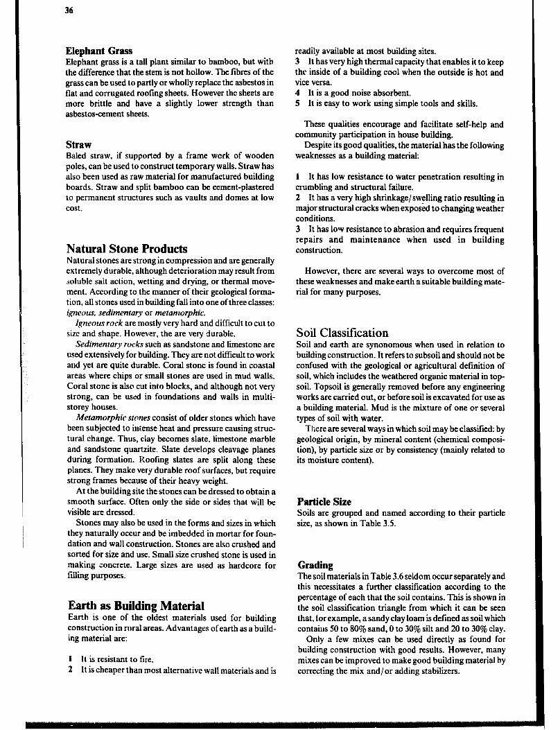
36
Elephant Grass Elephant grass is a tall plant similar to bamboo, but with the difference that the stem is not hollow. The fibres of the grass can be used to partly or wholly replace the asbestos in flat and corrugated roofing sheets. However the sheets are more brittle and have a slightly lower strength than asbestos-cement sheets.
Straw Baled straw, if supported by a frame work of wooden poles, can be used to construct temporary walls. Straw has also been used as raw material for manufactured building boards. Straw and split bamboo can be cement-plastered to permanent structures such as vaults and domes at low cost.
Natural Stone Products Natural stones are strong in compression and are generally extremely durable, although deterioration may result from soluble sait action, wetting and drying, or thermal move- ment. According to the manner of their geological forma- tion, all stones used in building fall into one of three classes: igneow sedimentary or metamorphic.
Igneous rock are mostly very hard and difficult to cut to size and shape. However, the are very durable.
Sedimentary rocks such as sandstone and limestone are used extensively for building. They are not difficult to work and yet are quite durable. Coral stone is found in coastal areas where chips or small stones are used in mud walls. Coral stone is also cut int.o b!ocks, and although not very strong, can be used in foundations and walls in multi- storey houses.
Metamorphic stones consist of older stones which have been subjected to iniense heat and pressure causing struc- tural change. Thus, clay becomes slate, limestone marble and sandstone quartzite. Slate develops cleavage planes during formation. l?oo!ing slates are split along these planes. They make very durable roof surfaces, but require strong frames because of their heavy weight.
At the building site the stones can be dressed to obtain a smooth surface. Often only the side or sides that will be visible are dressed.
Stones may also be used in the forms and sizes in which they naturally occur and be imbedded in mortar for foun- dation and waU construction. Stones are also crushed and sorted for size and use. Small size crushed stone is used in making concrete. Large sizes are used as hardcore for filling purposes.
Earth as Building Material Earth is one of the oldest materials used for building construction in rural areas. Advantages of earth as a build- ing material are:
1 It is resistant to tire. 2 It is cheaper than most alternative wall materials and is
readily available at most building sites. 3 It has very high thermal capacity that enables it to keep the inside of a building cool when the outside is hot and vice versa. 4 It is a good noise absorbent. 5 It is easy to work using simple tools and skills.
These qualities encourage and facilitate self-help and community participation in house building.
Despite its good qualities, the material has the following weaknesses as a building material:
1 It has low resistance to water penetration resulting in crumbling and structural failure. 2 It has a very high shrinkage/swelling ratio resulting in major structural cracks when exposed to changing weather conditions. 3 It has 10~ resistance to abrasion and requires frequent repairs and maintenance when used in building construction.
However, there are several ways to overcome most of these weaknesses and make earth a suitable building mate- rial for many purposes.
Soil Classification Soil and earth are synonomous when used in relation to building construction. It refers to subsoil and should not be confused with the geological or agricultural definition of soil, which includes the weathered organic material in top- soil. Topsoil is generally removed before any engineering works are carried out, or before soil is excavated for use as a building material. Mud is the mixture of one or several types of soil with water.
There are several ways in which soil may be classified: by geological origin, by mineral content (chemical composi- tion), by particle size or by consistency (mainly related to its moisture content).
Particle Size Soils are grouped and named according to their particle size, as shown in Table 3.5.
Grading The soil materials in Table 3.6 seldom occur separately and this necessitates a further classification according to the percentage of each that the soil contains. This is shown in the soil classification triangle from which it can be seen that, for example, a sandy clay loam is defined as soil which contaius SO to 80% sand, 0 to 30% silt and 20 to 30% clay.
Only a few mixes can be used directly as found for building construction with good results. However, many mixes can be improved to make good building material by correcting the mix and/ or adding stabilizers.
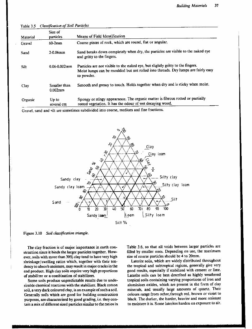
Building Materials 37
Table 3.5 Classification of Soil Particles
Size of Material particles Means of Field Identification
Gravel 60-2mm Coarse pieces of rock, which are round, flat or angular.
Sand 2-0.06mm Sand breaks down completely when dry, the particles are visible to the naked eye and gritty to the fingers.
Silt 0.06-0.002mm Particles are not visible to the naked eye, but slightly gritty to the fingers. Moist lumps can be moulded but not rolled into threads. Dry lumps are fairly easy to powder.
Clay Smaller than Smooth and greasy to touch. Holds together when dry and is sticky when moist. 0.002mm
Organic up to Spongy or stingy appearance. The organic matter is fibrous rotted or partially several cm rotted vegetation. It has the odour of wet decaying wood.
Gravel, sand and silt are sometimes subdivided into coarse, medium and fine fractions.
Sand --.-~
2 /’ Clay loam
$7
lfiii?L 2%
5 Silty clay
+L 25 .-Silty clay loam
[kam bilty loam
Silt %
Figure 3.10 Soil classtfzcation triangle.
The clay fraction is of major importance in earth con- struction since it binds the larger particles together. How- ever, soils with more than 30% clay tend to have very high shrinkage/swelling ratios which, together with their ten- dency to absorb moisture, may result in major cracks in the end product. High clay soils require very high proportions of stabilizer or a combination of stabilizers.
Some soils produce unpredictable results due to unde- sirable chemical reactions with the stabilizer. Black cotton soil, a very dark coloured clay, is an example of such a soil. Generally soils which are good for building construction purposes, are characterised by good grading, i.e. they con- tain a mix of different sized particles similar to the ratios in
Table 3.6, so that all voids between larger particles are filled by smaller ones. Depending on use, the maximum size of course particles should be 4 to 20mm.
Laterite soils, which are widely distributed throughout the tropical and subtropical regions, generally give very good results, especially if stabilized with cement or lime. Laterite soils can be best described as highly weathered tropical soils containing varying proportions of iron and aluminium oxides, which are present in the form of clay minerals, and usually large amounts of quartz. Their colours range from oclue,through red, brown or violet to black. The darker, the harder, heavier and more resistant to moisture it is. Some laterites harden on exposure to air.
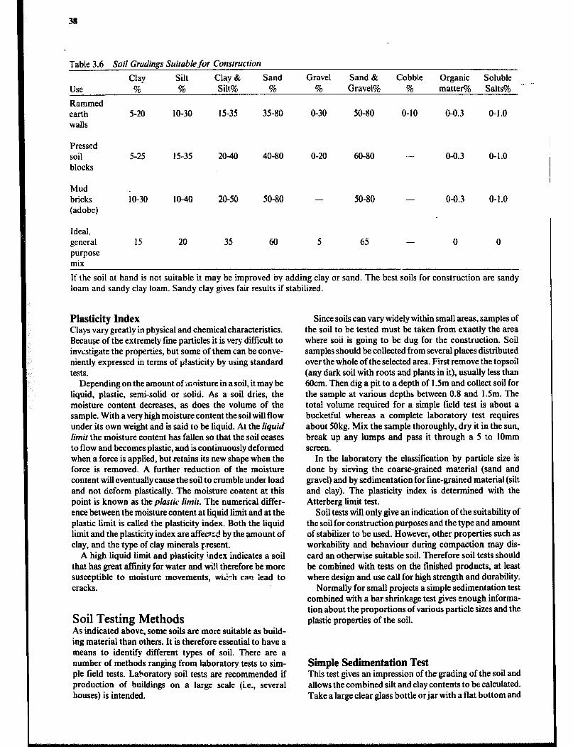
38
Table 3.6 Soil Grudings Suitable for Construction
Clay silt Clay & Sand Gravel Sand & Cobble Organic Soluble
Use % % Silt% % % Gravel% % matter% Salts% .- ‘-
Rammed earth 5-20 IO-30 15-35 35-80 O-30 50-80 O-10 04.3 o-1 .o walls
Pressed soil blocks
5-25 15-35 2040 40-80 O-20 60-80 -- o-O.3 O-l.0
Mud bricks (adobe)
;o-30 IO-40 20-50 50-80 - 50-80 - o-O.3 O-1.0
Ideal, general 15 20 35 60 5 65 - 0 0 purpose mix
If the soil at hand is not suitable it may be improved by adding clay or sand. The best soils for construction are sandy loam and sandy clay loam. Sandy clay gives fair results if stabilized.
Plasticity Index Clays vary greatly in physical and chemical characteristics. Because of the extremely fine particles it is very difficult to investigate the properties, but some of them can be conve- niently expressed in terms of p!asticity by using standard tests.
Depending on the amount of .mnisture in a soil, it may be liquid, plastic, semi-solid or :;olid. As a soil dries, the moisture content decreases, as does the volume of the sample. With a very high moisture content the soil will flow under its own weight and is said to be liquid. At the liquid limit the moisture content has fallen so that the soil ceases to flow and becomes plastic, and is continuously deformed when a force is applied, but retains its new shape when the force is removed. A further reduction of the moisture content will eventually cause the soil to crumble under load and not deform plastically. The moisture content at this point is known as the plastic limit. The numerical differ- ence between the moisture content at liquid lit and at the plastic limit is called the plasticity index. Both the liquid limit and the plasticity index are affected by the amount of clay, and the type of clay minerals present.
A high liquid limit and plasticity index indicates a soil that has great affmity for water and wi!l therefore be more susceptible to moisture movements, wtOh can iead to cracks.
Soil Testing Methods As indicated above, some soils are more suitable as build- ing material than others. It is therefore essential to have a means to identify different types of soil. There are a number of methods ranging from laboratory tests to sim- ple field tests. Laboratory soil tests are recommended if production of buildings on a large scale (i.e., several houses) is intended.
Since soils can vary widely within small areas, samples of the soil to be tested must be taken from exactly the area where soii is going to be dug for the construction. Soil samples should be collected from several places distributed over the whole of the selected area. First remove the topsoil (any dark soil with roots and plants in it), usually less than 6Ocm. Then dig a pit to a depth of 1.5m and collect soil for the sample at various depths between 0.8 and 1.5m. The total volume required for a simple field test is about a bucketful whereas a complete laboratory test requires about 50kg. Mix the sample thoroughly, dry it in the sun, break up any lumps and pass it through a 5 to 1Omm screen.
In the laboratory the classification by particle size is done by sieving the coarse-grained material (sand and gravel) and by sedimentation for fine-grained material (silt and clay). The plasticity index is determined with the Atterberg limit test.
Soil tests will only give an indication of the suitability of the soil for construction purposes and the type and amount of stabilizer to be used. However, other properties such as workability and behaviour during compaction may dis- card an otherwise suitable soil. Therefore soil tests should be combined with tests on the finished products, at least where design and use call for high strength and durability.
Normally for small projects a simple sedimentation test combined with a bar shrinkage test gives enough informa- tion about the proportions of various particle sizes and the plastic properties of the soil.
Simple Sedimentation Test This test gives an impression of thegrading of the soil and allows the combined silt and clay contents to be calculated. Take a large clear glass bottle orjar with a flat bottom and
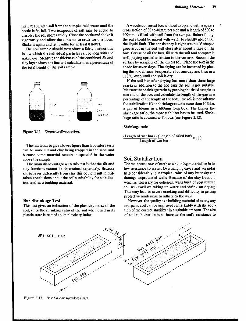
Building Materials 39
fill it I,‘3 full with soil from the sample. Add water until the bottle is z/3 full. Two teaspoons of salt may be added to dissolve the soil more rapidly. Close the bottle and shake it vigorously and allow the contents to settle for one hour. Shake it again and let it settle for at least 8 hours.
The soil sample should now show a fairly distinct line below which the individual particles can be seen with the naked eye. Measure the thickness of the combined silt and clay layer above the line and calculate it as a percentage of the total height of the soil sample.
A wooden or metal box without a top and with a square cross section of 30 to 40mm per side and a length of 500 to 6OOmm, is tilled with soil from the sample. Before filling, the soil should be mixed with water to slightly more than the liquid limit. The consistency is right when a V-shaped groove cut in the soil will close after about 5 taps on the box. Grease or oil the box, fill with the soil and compact it well, paying special attention to the comers. Smooth the surface by scraping off the excess soil. Place the box in the shade for seven days. The drying can be hastened by plac- ing the box at room temperature for one day and then in a 1 10°C oven until the soil is dry.
If the soil bar after drying has more than three large cracks in addition to the end gaps the soil is not suitable. Measure the shrinkage ratio by pushing the dried sample to one end of the box and calculate the length of the gap as a percentage of the length of the box. The soil is not suitable for stabilization if the shrinkage ratio is more than 10% i.e. a gap of 60mm in a 600mm long box. The higher the shrinkage ratio, the more stabilizer has to be used. Shrin- kage ratio is counted as follows (see Figure 3.12).
Shrinkage ratio =
Figure 3.11 Sinlpie sedimentation. (Length of wet bar) - (Length of dried bar) x 1OO
Length of wet bar The test tends to give a lower figure than laboratory tests
due to some silt and clay being trapped in the sand and because some material remains suspended in the water above the sample.
The main disadvantage with this test is that the silt and clay fractions cannot be determined separately. Because silt behaves differently from clay this could result in mis- taken conclusions about the soil’s suitability for stabiliza- tion and as a building material.
Bar Shrinkage Test This test gives an indication of the plasticity index of the soil, since the shrinkage ratio of the soil when dried in its plastic state is related to its plasticity index.
Soil Stabilization The main weakness of earth as a building material lies in its low resistance to water. Overhanging eaves and verandas help considerably, but tropical rains of any intensity can damage unprotected walls. Because of the clay fraction, which is necessary for cohesion, walls built of unstabilized soil will swell on taking up water and shrink on drying. This may lead to severe cracking and difficulty in getting protective renderings to adhere to the wall.
However, the quality as a building material of nearly any inorganic soil can be improved remarkably with the addi- tion of the correct stabilizer in a suitable amount. The aim of soil stabilization is to increase the soil’s resistance to
WET SOIL BAR
Figure 3.12 Box for bar shrinkage test.
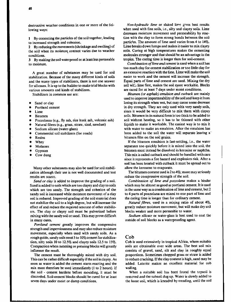
destructive weather conditions in one or more of the fol-
lowing ways:
1 By cementing the particles of the soil together, leading to increased strength and cohesion. 2 By reducing the movements (shrinkage and swelling) of the soil when its moisture, content varies due to weather conditions. 3 By making the soil waterproof or at least less permeable to moisture.
A great number of substances may be used for soil stabilization. Because of the many different kinds of soils and the many types of stabilizers, there is not one answer for all cases. It is up to the builder to make trial blocks with various amounts and kinds of stabilizers.
Stabilizers in common use are:
l Sand or clay 0 Portland cement l Lime l Bitumen l Pozzolanas (e.g., fly ash, rice husk ash, volcanic ash) l Natural fibres (e.g., grass, straw, sisal, sawdust) 0 Sodium silicate (water-glassj 0 Commercial soil stabilizers (for roads) l Resins l Whey 0 Molasses 0 Gypsum l Cow dung
Many other substances may also be used for soil stabili- zation although their use is not well documented and test mr,.ltr . “JU1.0 XC SCBiCC.
Sand or clay is added to improve the grading of a soil. Sand is added to soils which are too clayey and clay to soils which are too sandy. The strength and cohesion of the sandy soil is increased while moisture movement of a clay soil is reduced. Improved grading of the soil material does not stabilize the soil to a high degree, but will increase the effect of and reduce the required amount of other stabiliz- ers. The clay or clayey soil must be pulverized before mixing with the sandy soil or sand. This may prove difficult in many cases.
Portland cement greatly improves the compressive strength and imperviousness and may also reduce moisture movement, especially when used with sandy soils. As a rough guide, sandy soils need 5 to 10% cement for stabiliza- tion, silty soils 10 to 12.5% and clayey soils 12.5 to 15%. Compaction when ramming or pressing blocks will greatly influence the result.
The cement must be thoroughly mixed with dry soil. This can be rather difficult especially if the soil is clayey. As soon as water is added the cement starts reacting and the mix must therefore be used immediately (1 to 2 hours). If the soil - cement hardens before moulding, it must be discarded. Soil-cement blocks should be cured for at least seven days under moist or damp conditions.
Non-hydraulic lime or slaked live gives best results when used with fine soils, i.e., silty and clayey soils. Lime decreases moisture movement and permeability by reac- tion with the clay to form strong bonds between the soil partic!es. The amount of lime used varies from 4 to 14%. Lime breaks down lumps and makes it easier to mix clayey soils. Curing at high temperatures makes the cementing molecules stronger and that should be an advantage in the tropics. The curing time is longer than for soil-cement.
Combination of lime andcement is used when a soil has too much clay for cement stabilization or too little clay for an extensive reaction with the lime. Lime will make the soil easier to work and the cement will increase the strength. Equal parts of lime and cement are used. Mixing the dry soil wit:i lie first, makes the soil more workable. Blocks are cured for at least 7 days under moist conditions.
Bitumen (or asphalt) emulsion and cutback are mainly used to improve impermeability of the soil and keep it from losing its strength when wet, but may cause some decrease in dry strength. They are only used with very sandy soils, since it would be very difficult to mix them with clayey soils. Bitumen in its natural form is too thick to be added to soil without heating, so it has to be thinned with other liquids to make it workable. The easiest way is to mix it with water to make an emulsion. After the emulsion has been added to the soil the water will separate leaving a’ bitumen film on the soil grains.
If the bitumen emulsion is fast-settling, i.e., the water separates too quickly before it is mixed into the soil, the bitumen must instead be dissolved in kerosine or naphtha. This mix is called cutback and should be handled with care since it represents a fire hazard and explosion risk. After a soil has been treated with cutback it must be spread out to allow the kerosene to evaporate.
The bitumen content used is 2 to 4%; more may seriously reduz the compressive strength of the soil.
Combination of lime and pozzolana makes a binder which may be almost as good as portland cement. It is used in the same way as a combination of lime and cement, but 2 to 4 parts of pozzolana are mixed to one part of lime and the curing time is longer than for ordinary cement.
Natural fibres, used in a mixing ratio of about 4%, greatly reduce moisture movement, but will make dry soil blocks weaker and more permeable to water.
Sodium silicate or water-glass is best used to coat the outside of soil blocks as a waterproofing agent.
Cob Cob is used extensively in tropical Africa, where suitable soils are obtainable over wide areas. The best soil mix consists of gravel, sand, silt and clay in roughly equal proportions. Sometimes chopped grass or straw is added to reduce cracking. If the clay content is high, sand may be added. Laterite makes an excellent material for cob walling.
When a suitable soil has been’ found the topsoil is removed and the subsoil dug up. Water is slowly added to the loose soil, which is kneaded by treading, until the soil
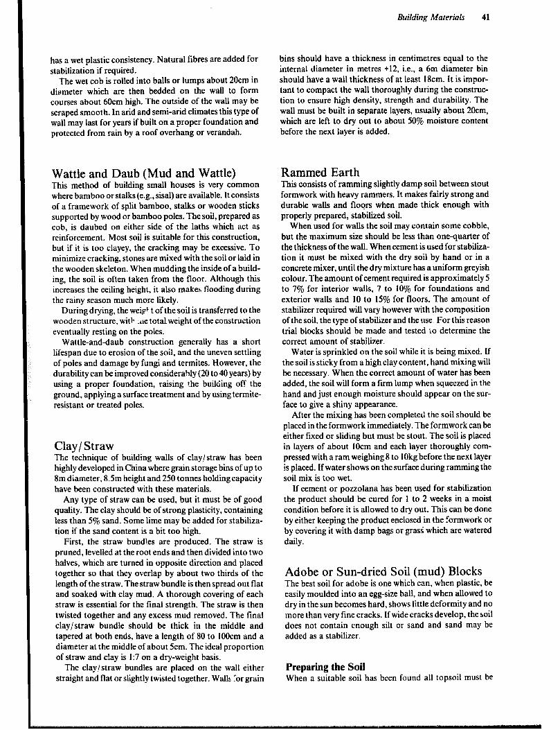
has a wet plastic consistency. Natural fibres are added for stabilization if required.
The wet cob is rolled into balls or lumps about 20cm in dia.meter which are then bedded on the wall to form courses about 6Ocm high. The outside of the wall may be scraped smooth. In arid and semi-arid climates this type of wall may last for years if built on a proper foundation and protected from rain by a roof overhang or verandah.
Wattle and Daub (Mud and Wattle) This method of building small houses is very common where bamboo or stalks (e.g., sisal) are available. It consists of a framework of split bamboo, stalks or wooden sticks supported by wood or bamboo poles. The soil, prepared as cob, is daubed on either side of the laths which act as reinforcement. Most soil is suitable for this construction, but if it is too clayey. the cracking may be excessive. To minimize cracking, stones are mixed with the soil or laid in the wooden skeleton. When mudding the inside of a build- ing, the soil is often taken from the floor. Although this increases the ceiling height, it also makes flooding during the rainy season much more likely.
During drying, the weip’t of the soil is transferred to the wooden structure. with .,ie totalweight of the construction eventually resting on the poles.
Wattle-and-daub construction generally has a short lifespan due to erosion of the soil, and the uneven settling of poles and damage by fungi and termites. However, the durability can be improved considerably (20 to 40 years) by using a proper foundation, raising the building off the ground, applying a surface treatment and by using termite- resistant or treated poles.
Clay/ Straw The technique of building walls of clay/straw has been highly developed in China where grain storage bins of up to 8m diameter, 8.5m height and 250 tonnes holding capacity have been constructed with these materials.
Any type of straw can be used, but it must be of good quality. The clay should be of strong plasticity, containing less than 5% sand. Some lime may be added for stabiliza- tion if the sand content is a bit too high.
First, the straw bundles are produced. The straw is pruned, levelled at the root ends and then divided into two halves, which are turned in opposite direction and placed together so that they overlap by about two thirds of the length of the straw. The straw bundle is then spread out flat and soaked with clay mud. A thorough covering of each straw is essential for the final strength. The straw is then twisted together and any excess mud removed. The final clay/straw bundle should be thick in the middle and tapered at both ends, have a length of 80 to IOOcm and a diameter at the middle of about 5cm. The ideal proportion of straw and c!ay is I:7 on a dry-weight basis.
The clay/straw bundles are placed on the wail either straight and flat or slightly twisted together. Walls lor grain
Building Materials 41
bins should have a thickness in centimetres equal to the internal diameter in metres +12, i.e., a 6m diameter bin should have a wall thickness of at least I8cm. It is impor- tant to compact the wall thoroughly during the construc- tion to ensure high density, strength and durability. The wall must be built in separate layers, usually about 20cm, which are left to dry out to about 50% moisture content before the next layer is added.
Rammed Earth This consists of ramming slightly damp soil between stout formwork with heavy rammers. It makes fairly strong and durable walls and floors when made thick enough with properly prepared, stabilized soil.
When used for walls the soil may contain some cobble, but the maximum size should be less than one-quarter of the thickness of the wall. When cement is used for stabiliza- tion it must be mixed with the dry soil by hand or in a concrete mixer, until the dry mixture has a uniform greyish colour. The amount of cement required is approximately 5 to 7% for interior walls, 7 to 10% for foundations and exterior walls and 10 to 15% for floors. The amount of stabilizer required will vary however with the composition of the soil, the type of stabilizer and the use For this reason trial blocks should be made and tested io determine the correct amount of stabilizer.
Water is sprinkled on the soil while it is being mixed. If the soil is sticky from a high clay content, hand mixing will be necessary. When the correct amount of water has been added, the soil will form a firm lump when squeezed in the hand and just enough moisture should appear on the sur- face to give a shiny appearance.
After the mixing has been completed the soil should be placed in the formwork immediately. The formwork can be either fixed or sliding but must be stout. The soil is placed in layers of about IOcm and each layer thoroughly com- pressed with a ram weighing 8 to 1Okg before the next layer is placed. If water shows on the surface during ramming the soil mix is too wet.
If cement or pozzolana has been used for stabilization the product should be cured for 1 to 2 weeks in a moist condition before it is allowed to dry out. This can be done by either keeping the product enclosed in the formwork or by covering it with damp bags or grass‘ which are watered daily.
Adobe or Sundried Soil (mud) Blocks The best soil for adobe is one which can, when plastic, be easily moulded into an egg-size ball, and when allowed to dry in the sun becomes hard, shows little deformity and no more than very fine cracks. If wide cracks develop, the soil does not contain enough silt or sand and sand may be added as a stabilizer.
Preparing the Soil When a suitable soil has been found all topsoil must be
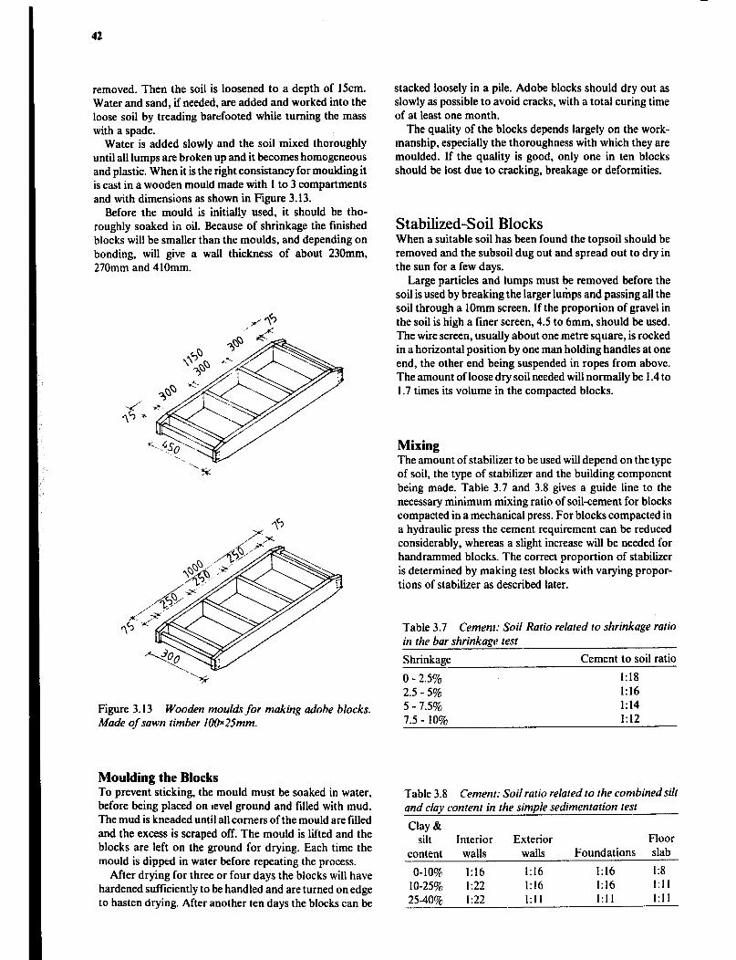
42
removed. Then the soil is loosened to a depth of 15cm. Water and sand, if needed, are added and worked into the loose soil by treading barefooted while turning the mass with a spade.
Water is added slowly and the soil mixed thoroughly until all lumps are broken up and it becomes homogeneous and plastic. When it is the right consistancy for moulding it is cast in a wooden mould made with 1 to 3 compartments and with dimensions as shown in Figure 3.13.
Before the mould is initially used, it should be tho- roughly soaked in oil. Because of shrinkage the finished blocks will be smaller than the moulds, and depending on bonding, will give a wag thickness of about 230mm, 270mm and 4 IOmm.
Figure 3.13 Wooden moulds for making adobe blocks. Made of sawn timber lOOx25mm.
Moulding the Blocks To prevent sticking, the mould must be soaked in water, before being placed on revel ground and tilled with mud. The mud is kneaded until all comers of the mould are filled and the excess is scraped off. The mould is lifted and the blocks are left on the ground for drying. Each time the mouid is dipped in water before repeating the process.
After drying for three or four days the blocks will have hardened sufficiently to be handled and are turned on edge to hasten drying. After another ten days the blocks can be
stacked loosely in a pile. Adobe blocks should dry out as slowly as possible to avoid cracks, with a total curing time of at least one month.
The quality of the blocks depends largely on the work- manship, especially the thoroughness with which they are moulded. If the quality is good, only one in ten blocks should be lost due to cracking, breakage or deformities.
Stabilized-Soil Blocks When a suitable soil has been found the topsoil should be removed and the subsoil dug out and spread out to dry in the sun for a few days.
Large particles and lumps must be removed before the soil is used by breaking the larger lumps and passing all the soil through a 1Omm screen. If the proportion of gravel in the soil is high a finer screen, 4.5 to 6mm, should be used. The wire screen, usually about one metre square, is rocked in a horizontal position by one man holding handles at one end, the other end being suspended in ropes from above. The amount of loose dry soil needed will normally be I .4 to I .7 times its volume in the compacted blocks.
Mixing The amount of stabilizer to be used will depend on the type of soil, the type of stabilizer and the building component being made. Table 3.7 and 3.8 gives a guide line to the necessary minimum mixing ratio of soil-cement for blocks compacted in a mechanical press. For blocks compacted in a hydraulic press the cement requirement can be reduced considerably, whereas a slight increase will be needed for handrammed blocks. The correct proportion of stabilizer is determined by making test blocks with varying propor- tions of stabilizer as described later.
Table 3.7 Cement: Soil Ratio related to shrinkage ratio in the bar shrinkage test
Shrinkage Cement to soil ratio
0 - 2.5% 1:I8
2.5 - 5% I:16
5 - 7.5% 1:14
7.5 - 10% 1:12
Table 3.8 Cement: Soil ratio related to the combined silt and clay content in the simple sedimentation test
Clay & silt Interior Exterior Floor
content walls walls Foundations slab
O-IO% I:16 I:16 I:16 I:8
I O-2570 I:22 I:16 I:16 1:11
2540% I:22 I:11 I:11 I:11

Building Materials 43
Table 3.9 Batching for Stabilized-Soil Blocks
Approx. Requirement Number of blocks per 50kg cement
Prpportions cement of Ioose Size of blocks cement:soil content soil per by volume by weight 50kg cement 290x 140x50 290s 14OJW 290~140~120 290~ 140x 140 290~215~140
I:22 5% I080 litre 366 203 152 130 85 I:18 6% 880 litre 301 167 125 107 70 I:16 7% 780 litrc 268 149 III 95 62
I:14 8% 690 litre 235 131 98 84 54 I:12 9% 590 litre 203 113 84 72 47 I:1 I 10% 540 litre 187 104 78 66 43
I:10 11% 490 litre 170 94 71 61 39 I:9 12% 440 litre 154 85 64 55 36 1:8.5 13% 420 litre 146 81 61 52 34
I:8 15% 390 litre 138 76 57 49 32
The importance of thoroughly mixing the dry soil first
with the stabilirer and then with the moisture, in two distinct stsps. cannot be emphasized too strongly.
The quantity of cement and dry soil is measured with a measuring box, bucket or tin, never with a shovel, and put either on a clean, even and hard surface for hand mixing or into a drum-type mixer (concrete mixer). They are mixed until the dry mixture has a uniform greyish colour. Water is added, preferably through a sprinkler, while the mixing is continued. When the correct amount of water has been added, the soil, when squeezed into a ball, should retain its
shape without soiling the hand. The ball should be capabie of being pulled apart without disintegrating, but it should disintegrate when dropped from shoulder height on to a hard surface.
Compaction by Hand-ramming Moulds with one or more compartments can be made either from hard wood or steel. The mould should have hinges at one or two corners so that it can be opened easily without spoiling the block. The mould has no bottom and is preferably placed on a pallet rather than directly on the ground when moulding the block.
The mould is treated as often as required with oil to make the block surface smooth and to prevent the block from sticking to &he mould. The soil mixture should be placed in layers in the mould and each layer thoroughly compacted with a flat-bottomed ram weighing 4 lo 5kg. Each block may need as many as 80 good blows with the ram. The top of the block is leveled off and the block and mould carried to the curing store where the mould is removed, and then the whole process is repeated.
Compaction with a Mechanical Press There are a numerous number of mechanical block-
making machines on the market. Both motor driven, which can make several blocks at a time, and hand-operated.
Hinges -
Lock
Figure 3.14 Mould for hand-rammed stabilized-soil blocks made of 20mm plane timber.
They ail consist of a metal mould in which a moist soil mix is compressed.
Figure 3. I5 Mechanical press fcr block making.
44
The moulding for a hand-operated press is done as follows:
a The inside of the compactionchamber is cleaned and oiled and a pallet is placed in the bottom, if required. b A measured amount of soil mix is poured into the compaction-chamber and the soil compacted into the corners by hand. c The lid is closed and the handle pulled down. The amount of soil mix is correct if the handle can be moved down to stop a little above a horizontal level. d The block is ejected and carried on the pallet, to the curing site and the pallet is returned to the press for re-use.
Curing of Blocks Soil-cement blocks shcnld be placed on the ground in the shade, as close together as possible and be kept damp (e.g., with wet grass). After one or two days the blocks can be carefully stacked and again kept damp for one to two weeks. After this period the blocks are allowed to air-dry for two to three weeks in an openly stacked pile before use.
Testing of Blocks In the laboratory, dry strength and wet strength are deter- mined by crushing two well-cured blocks in an hydraulic press, the first in a dry state, and the second after having been soaked in water for 24 hours. Durability is tested by s:rzying the blocks with water according to a standard procedure and making observations for any erosion or pitting.
In order to find out how much stabilizer is required, the following simple weather resistance test carried out in the field may give a satisfactory answer.
At least three different soil mixes having different stabilizer-soil ratios are prepared and at least three blocks are made from each of the different mixes.
Mixing, compaction and curing must be done in the same way as planned for the whole block production. At the end of the curing period three blocks are selected from each set, immersed in a tank, pond or stream all night and dried in the sun all day. This wetting and drying is repeated for seven days.
The correct amount of stabilizer to use is the smallest amount with which all the three blocks in a set pass the test. A few small holes can be allowed on the compaction surface, but if many holes appear on all surfaces the blocks are too weak. If the blocks have passed the test and the dry block produces a metallic ring when tapped with a hammer, they will have satisfactory durability and hardness.
If the blocks fail the test, the reason may be any of the following:
Unsuitable soil; insufficient amount of stabilizer; incorrect type of stabilizer; inadequately dried or lumpy soil; lumpy cement; insut.icient mixing of the stabilizer; too much or
too little water added; not enough compaction; incorrect curing.
Comparison of Masonry Units Made of Various Materials There are many methods of making bricks and blocks, several of which are suitable for local production since they are labour intensive but do not require especially skilled labour.
The decision on which method of block or brick making to use depends on several factors, such as:
0 the raw materials available; l the characteristics of the soil; l raw material and production costs; 0 the requisite standards of stability, compression strength, water resistance, etc. 3 N/ mm2 is often regarded as the minimum compressive strength for use in one-storey buildings; l the existing facilities for the maintenance of production tools and machines; 0 the needed productivity.
Burnt-Clay Bricks Burnt-clay bricks have good resistance to moisture, insects and erosion and create a good room environment. They are medium in cost and have medium-to-high compressive strength.
Bricks can be made with sophisticated factory methods, simple labour-intensive methods or a range of mechanized technologies in between. The labour-intensive production methods are most suitable for rural areas where the demand for bricks is limited. The bricks produced by hand will have relatively lower quality, especially compressive strength, and will tend to have irregular dimensions, How- ever, they are economical and require little capital invest- ment or transportation cost. Bricks made in this manner have been used in buildings which have lasted for centuries. Their longevity has depended on the quality of the ingre- dients, the skill of the artisans and the climate in which they were used.
Brick Making Four main ingredients are required for brick making: suit- able.clay and sand, water, fuel and manpower. The clay must be easily available, be plastic when mixed with small amounts of water, develop strength upon drying and develop hard and durable use-strength when burned.
Suitable soils contain 25 to 50% clay and silt and 50 to 75% coarser material as determined by the simple sedimen- tation test. The soil must be well graded. Another test consists of rolling out by hand on a flat surface a long cylinder with a IOmm diameter from moistened soil and
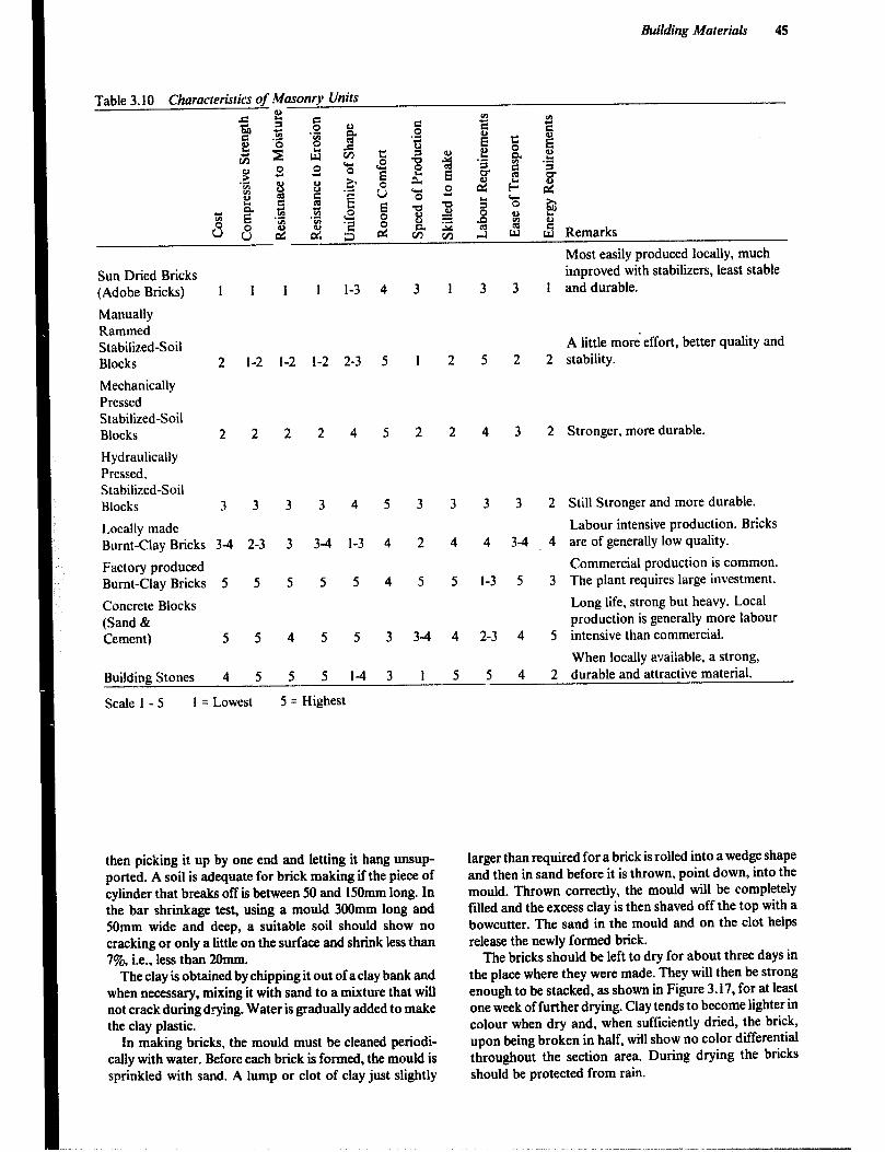
Building Materials 45
Table 3.10 Characteristics of Masonry Units
Sun Dried Bricks (Adobe Bricks) 1 1 1 1 1-3 4
Manually Rammed Stabilized-Soil Blocks 2 1-2 1-2 1-2 2-3 5
Mechanically Pressed Stabilized-Soil Blocks 2 2 2 2 4 5
Hydraulically Pressed. Stabilized-Soil Blocks 3 3 3 3 4 5
Locally made Burnt-Clay Bricks 3-4 2-3 3 34 l-3 4
Factory produced Burnt-Clay Bricks 5 5 5 5 5 4
Concrete Blocks (Sand & Cement) 5 5 4 5 5 3
3
1
2
3
2
5
3-4
1
2
2
3
4
5
4
5
Most easily produced locally, much unproved with stabilizers, least stable
3 3 1 and durable.
A little more effort, better quality and
5 2 2 stability.
4 3 2 Stronger, more durable.
3 3 2 Still Stronger and more durable.
Labour intensive production. Bricks 4 34 4 are of generally low quality.
Commercial production is common. l-3 5 3 The plant requires large investment.
Long life, strong but heavy. Local production is generally more labour
2-3 4 5 intensive than commercial.
When locally available, a strong,
Building Stones 4 5 5 5 14 3 I I 5 4 2 durable and attractive material.
Scale 1 - 5 1 = Lowest 5 = Highest
then picking it up by one end and letting it hang unsup- ported. A soil is adequate for brick making if the piece of cylinder that breaks off is between 50 and 150mm long. In the bar shrinkage test, using a mould 300mm long and 5Omm wide and deep, a suitable soil should show no cracking or only a little on the surface and shrink less than 7% i.e., less than 2Omn.r.
The clay is obtained by chipping it out of a clay bank and when necessary, mixing it with sand to a mixture that will not crack during drying. Water is gradually added to make the clay plastic.
In making bricks, the mould must be cleaned periodi- cally with water. Before each brick is formed, the mould is sprinkled with sand. A lump or clot of clay just slightly
larger than required for a brick is rolled into a wedge shape and then in sand before it is thrown, point down, into the mould. Thrown correctly, the mould will be completely filled and the excess clay is then shaved off the top with a bowcutter. The sand in the mould and on the clot helps release the newly formed brick.
The bricks should be left to dry for about three days in the place where they were made. They will then be strong enough to be stacked, as shown in Figure 3.17, for at least one week of further drying. Clay tends to become lighter in colour when dry and, when sufficiently dried, the brick, upon being broken in half, will show no color differential throughout the section area. During drying the bricks should be protected from rain.
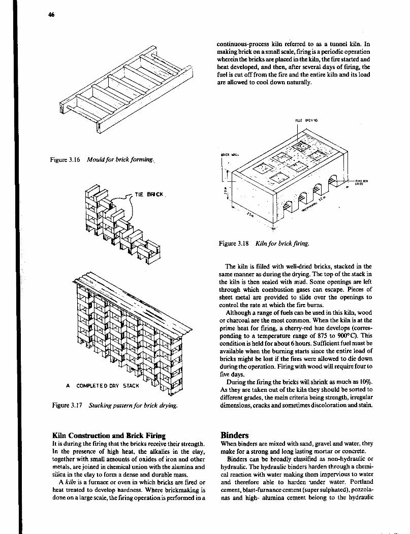
continuous-process kiln referred to as a tunnel kiln. In making brick on a small scale, firing is a periodic operation wherein the bricks are placed in the kiln, the fire started and heat developed, and then, after several days of firing, the fuel is cut off from the fire and the entire kiln and its load are allowed to cool down naturally.
GaICK WILL Figure 3.16 Mouldfor brick forming..
Figure 3.18 Kiln for brick firing.
The kiln is filled with well-dried bricks, stacked in the same manner as during the drying. The top of the stack in the kiln is then sealed with mud. Some openings are left through which combustion gases can escape. Pieces of sheet metal are provided to slide over the openings to control the rate at which the fire bums.
Although a range of fuels can be used in this kiln, wood or charcoal are the most common. When the kiln is at the prime heat for firing, a cherry-red hue develops (corres- ponding to a temperature range of 875 to 9OOOC). This condition is held for about 6 hours. Sufficient fuel must be available when the burning starts since the entire load of bricks might be lost if the fires were allowed to die down during the operation. Firing with wood will require four to five days.
A COMPLETED DRY STAC
Figure 3. I7 Stacking pattern for brick drying.
During the firing the bricks will shrink as much as 10%. As they are taken out of the kiln they should be sorted to different grades, the main criteria being strength, irregular dimensions, cracks and sometimes discoloration and stain.
Kiln Construction and Brick Firing It is during the firing that the bricks receive their strength. In the presence of high heat, the alkalies in the clay, together with small amounts of oxides of iron and other metals, are joined in chemical union with the alumina and silica in the clay to form a dense and durable mass.
A kiln is a furnace or oven in which bricks are fired or heat treated to develop hardness. Where brickmaking is done on a large scale, the firing operation is performed in a
Binders When binders are mixed with sand, gravel and water, they make for a strong and long Ming mortar or concrete.
Binders can be broadly classified as non-hydraulic or hydraulic. The hydraulic binders harden through a chemi- cal reaction with water making them impervious to water and therefore able to harden ‘under water. Portland cement, blast-furnance cement (super sulphated), pozzola- nas and high- alumina cement beiong to the hydraulic
binders. High-calcium limes (fat cr pure limes) are non- hydraulic since they harden by reaction with the carbon dioxide in the air. If. however lime is produced from limes- tone containing clay, compounds similar to those in por- tland cement will be formed, i.e., hydraulic lime.
Lime .!Von-hydraulic lime is high-calcium limes that are pro- duced by burning fairly pure limestone, essentially calcium carbonate, so as to drive off the carbon dioxide leaving calcium oxide or quicklime. The burning process requires a temperature of 900 to 1100°C. Quicklime must be handled with great care because it reacts with moisture on the skin and the heat produced may cause burns. When water is added to quicklime considerable heat is evolved, expansion takes place breaking down the quick lime pieces to a tine powder and the resulting product is calcium hydroxide, also called hydrated lime, or siaked lime.
After drying the powder is passed through a 3mm sieve, and poured into bags for storage (in dry conditions) and distribution.
Process Substances Chemically Burning Limestone - Quick lime CaC03 -
CaO + CO2 Slaking Quick lime - Slaked lime CaO + Hz0 -
Ca(OH)z Hardening Slaked lime - Limestone Ca(OH)2 + CO2 -
CaCO3 + H20
Slaked lime is mainly used in building because it is fat, i.e., it makes workable mortar and rendering and plaster mixes. A lime mortar becomes stiff initially by evaporation or loss of water to absorptive materials such as bricks, but subsequent hardening depends on the chemical reaction with carbon dioxide from the air (carbonation) reforming the original calcium carbonate (limestone).
Non-hydraulic lime is also produced from limestones with a high content of magnesium carbonate. It is less easily slaked, but some of the magnesium oxide remaining unslaked may carbonate and produce greater strength than high-calcium lime.
Hydraulic lime is produced by mixing and grinding together limestone and clay material, and then burning it in a kiln.
It is stronger but less fat or plastic than non-hydraulic lime. During the burning the calcium oxide from the limes- tone will react with siliceous matter from the clay forming dicalcium silicate. This compound may react with water forming ‘mineral glue’ - tricalcium disihcate hydrate. The reaction is slow and may take weeks or months, but after some time a very good strength is achieved.
The reaction forming dicalcium silicate requires a very high temperature to becomplete. In practical production a lower temperature of 1200°C is used leaving some of the ingredients in their original state. Due to the temperature the limestone will lose the carbon dioxide and thus form
Building Materials 41
quicklime. If a correct amount of water is added the quick- lime will slake forming a fine powder. Note, however, that excess water will lead to premature hardening due to hydraulic reaction.
Cement Portland cement hardens more quickly and develops con- siderably higher strength than hydraulic lime. This is because cement contains tricalcium silicate. However, the manufacturing process is much more complicated than that of lime. The ingredients are mixed in definite and controlled proportions and then ground to a very fine powder. The fine grinding is necessary since the formation of tricalcium silicate can only take place in a solid state and therefore only the surface of the partic+? in the mix are accessible for the chemical reaction which requires a temperature of 1250 to 1900°C to be completed.
During the burning the small particles of limestone and clay are sintered together to clinker. After cooling this is ground to cement powder, a small amount of gypsum being added during the grinding. The finer the cement particles, the larger the surface arca which is available for hydration by water and the more rapid the setting and hardening occurs. Cement is normally sold in 50kg bags but occasionally is available in bulk at a lower price.
Ordinary portland cement is the least expensive and by far the most widely used type ofcement. It is suitable for all normal purposes.
Tapid-hardening portland cement is more finely ground and thus has a faster chemical reaction with water and develops strength more rapidly. It has the same strength after 7 days that ordinary portland cement has after 28 days. Early hardening may be useful where early stripping of form work and early loading of the structure is required.
Low-heat portland cement develops strength very slowly. It is used in very thick concrete work where the heat generated by the chemical reactions in ordinary portland cement would be excessive and lead to serious cracking.
Chemistry of Cement The main components of standard portland cement are:
l Lime (calcium oxide; 66%) in the fo.rm of limestone 0 Silica (silicum dioxide; 22%) a component in most quartz, which forms the particles of clays 0 Aluminium oxide (4%) found .r large quantities in many clays. The proportion of ahunin oxide in the clay can be adjusted by the addition of bauxit, which is mainly water soluble ahrminium oxide. 0 Iron oxide (3%) found in iron ore and in clay l Magnesium oxide (2%) 0 Sulphur dioxide (2%) 0 Miscellaneous components (1%)
The manufacturing process aims to produce a material with a high content of tricalcium silicate, usually 55 to 62%
of the crystals in the clinker. Other crystals formed are: about 15% dicalcium silicate, (the same component as the hydraulic binder in hydraulic lime), 8 to 10% trica!cium aluminate and 9% tetracalcium aluminate ferrite. Since cement sinters during the burning it is very important that no calcium oxide, quicklime, remains in the finished pro- duct. The quicklime will remain embedded in the clinker even after very fine grinding and not be available for slaking until the hardening process of the cement has gone quite far. When finally the quicklime particles are slaked they expand and break the structure already developed. The proportion of limestone in the initial mix must there- fore be within 0.1%.
When cement is mixed with water the chemical reactions which are so important for the hardening start. The most important is the forming of tricalcium disihcate hydrate, ‘mineral glue’, from hydrated calcium oxide and silica.
2(3CaO.SiOz) + 6HzO -+ 3Ca0*2SiOz*3HzO + 3Ca(OH)2 and 2(2CaOSiOz) + 3HzO + 3Ca0*2SiOr3HzO + Ca(OH)2
The reaction between dicalcium silicate and water is slow and will thus only contribute to the strength of the concrete after considerable time. Aluminate would inter- fere with these processes, hence the addition of gypsum at the end of the manufacturing process. The gypsum forms an insoluble compound with the aluminate.
In the process of hydration the cement will chemically bind water corresponding to about onequarter of its weight. Additional water evaporates leaving voids, which reduce the density and therefore Strength and durability of the end products.
Pozzolana A pozzolana is a siliceous material which, in finely divided form, can react with lime in the presence of moisture at normal temperatures and pressures to form compounds possessing cementious properties. Unfortunately the cementitious properties of pozzolana mixtures are highly variable and unpredictable.
A wide variety of materials, both natural and artificial may be pozzolanic. The silica content constitutes more than half the weight of the pozzolana. Volcanic ash was the first pozzolana used when the Romans made concrete from it for many large and durable buildings. Deposits of vol- canic ash are likely to be found wherever there are active or recently active volcanoes. Other natural pozzolana are derived from rock or earth in which the silica constituent contains the mineral opal and from the lateritic soils com- monly found in Africa. Artificial pozzolana includes fly ash from the combustion of coal in thermoelectric power plants, burnt clays and shales, blast furnace slag formed in the process of iron manufacture, and rice husk ash and the ash from other agricultural wastes.
The energy requirement for the manufacture of portland cement is very high. By comparison, lime and hydraulic
lime can be produced at less than half the energy require- ment, and natural pozzolana may be used directly without any processing. Artificial pozzolana requires some heating, but less than half as much as is required for lime production.
Pozzolana and lime can be produced with much less sophisticated technology than portland cement. This means that pozzolana can be produced at relatively low cost and requires much less foreign exchange than cement. However, it takes two to three times the volume of pozzo- lana required to make a concrete with the same strength as with portland cement and this adds to the cost for transport and handling.
The main use of pozzolanas is for lime-pozzolana mor- tars, for blended pozzolanic cements and as an admixture in concrete mix. Replacing up to 30% of the portland cement with pozzolana will produce 65 to 95Y0 of the strength of portland cement concrete at 28 days. The strength normally improves with age since pozzolana reacts more slowly than cement, and at one year about the same strength is obtained.
Concrete Concrete is a building material made by mixing cement paste (Portland cement and water) and aggregate (sand and stone). The cement-paste is the “glue” which binds the particles in the aggregate together. The strength of the cement-paste depends on the relative proportions of water and cement; a more diluted paste being weaker. Also the relative proportions of cement-paste and aggregate affects the strength; a higher proportion of the paste making stronger concrete. The concrete hardens through the chem- ical reaction between water and cement without the need for air. Once the initial set has taken place concrete cures well under water. Strength is gained gradually, depending on the speed of the chemical reaction.
Admixtures are sometimes included in the concrete mix to achieve certain properties. Reinforcement steel is used for added strength, particularly for tensile stresses. Concrete is normally mixed at the building site and placed in forms of the desired shape in the place the unit will occupy in the finished structure. Units can also be precast either at the building site or at a factory.
Properties of Concrete Concrete is associated with high strength, hardness, dura- bility, imperviousness and mouldability. It is 2 poor ther- mal insulator, but has high thermal capacity. Concrete is not flammable and has good fire resistance, but there is a serious loss of strength at high temperatures. Concrete made with ordinary portland cement has low resistance to acids and sulphates but good resistance to alkalies.
Concrete is a relatively expensive building material for farm structures. The cost can be’lowered if some of the portland cement is replaced with pozzolana. However, when pozzolanas are used the chemical reaction is slower
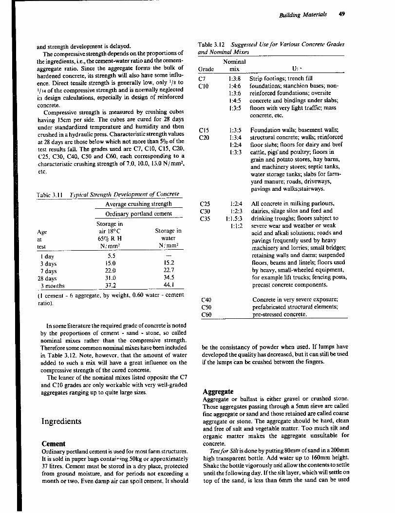
and strength development is delayed. The compressive strength depends on the proportions of
the ingredients, i.e., the cement-water ratio and the cement- aggregate ratio. Since the aggregate forms the bulk of hardened concrete, its strength will also have some influ- ence. Direct tensile strength is generally low, only I/S to I/ 14 of the compressive strength and is normally neglected in design calculations, especially in design of reinforced concrete.
Compressive strength is measured by crushing cubes having 15cm per side. The cubes are cured for 28 days under standardized temperature and humidity and then crushed in a hydraulic press. Characteristic strength values at 28 days are those below which not more than 5% of the test results fall. The grades used are C7, ClO, C15, C20, C25, C30, C40. C50 and C60, each corresponding to a characteristic crushing strength of 7.0, 10.0, 15.0 N/mm*, CW.
Table 3. I 1 Tvpica! Strengtlz Developmenr of Concrete
Average crushing strength
Ordinary portland cement
Storage in
Age air 18’C Storage in
at 65Vo R H water
test N/mm? N/mm2
1 day 5.5 -
3 days 15.0 15.2
7 days 22.0 22.7
28 days 31.0 34.5
3 months 37.2 44.1
(1 cement - 6 aggregate, by weight, 0.60 water - cement ratio).
In some literature the required grade of concrete is noted by the proportions of cement - sand - stone, so called nominal mixes rather than the compressive strength. Therefore some common nominal mixes have been included in Table 3.12. Note, however, that the amount of water added to such a mix will have a great influence on the compressive strength of the cured concrete.
The leaner of the nominal mixes listed opposite the C7 and Cl0 grades are only workable with very well-graded aggregates ranging up to quite large sizes.
Ingredients
Cement Ordinary portland cement is used for most farm structures. It is sold in paper bags contaiping 50kg or approximately 37 litres. Cement must be stored in a dry place, protected from ground moisture, and for periods not exceeding a month or two. Even damp air can spoil cement. It should
Building Materials 49
Table 3.12 Suggested Use for Various Concrete Grades and Nornina/ Mixes
Nominal Grade -- mix U! *
c7 Cl0
Cl5 c20
C25 c30 c35
c40 c50
1:3:8 1:4:6 1:3:6 1:4:5 1:3:5
1:3:5 1:3:4 1:2:4 1:3:3
1:2:4 1:2:3
1:1.5:3 1:1:2
Strip footings; trench fill foundations; stanchion bases; non- reinforced foundations; oversite concrete and bindings under slabs; floors with very light traffic; mass concrete, etc.
Foundation walls; basement walls; structural concrete; walls; reinforced floor slabs; floors for dairy and beef cattle, pigsand poultry; floors in grain and potato stores, hay barns, and machinery stores; septic tanks, water storage tanks; slabs for farm- yard manure; roads, driveways, pavings and walks;stairways.
All concrete in milking parlours, dairies, silage silos and feed and drinking troughs; floors subject to severe wear and weather or weak acid and alkali solutions; roads and pavings frequently used by heavy machinery and lorries; small bridges; retaining walls and dams; suspended floors, beams and lintels; floors used by heavy, small-wheeled equipment, for example lift trucks; fencing posts, precast concrete components.
Concrete in very severe exposure; prefabricated structural elements; pre-stressed concrete. C60
be the consistancy of powder when used. If lumps have developed the quality has decreased, but it can still be used if the lumps ‘can be crushed between the fingers.
Aggregate Aggregate or ballast is either gravel or crushed stone. Those aggregates passing through a 5mm sieve are caged fine aggregate or sand and those retained are called coarse aggregate or stone. The aggregate should be hard, clean and free of salt and vegetable matter. Too much silt and organic matter makes the aggregate unsuitable for concrete.
Testfor Silt is done by putting 80mm of sand in a 200mm high transparent bottle. Add water up to 160mm height. Shake the bottle vigorously arid allow the contents to settle until the following day. If the silt layer, which will settle on top of the sand, is less than 6mm the sand can be used

without further treatment. If the silt content is higher, the sand must be washed.
Test for Organic Matter is done by putting 80mm of sand in a 200mm high transparent bottle. Add a 3% SO~U-
tion of sodium hydroxide up to 120mm. Note that sodium hydroxide, which can be bought from a chemist, is danger- ous to the skin. Cork the bottle and shake it vigorously for 30 seconds and leave it standing until the following day. If the liquid on top of the sand turns dark brown or coffee coioured, the sand should not be used. ‘Straw” color is satisfactory for most jobs, but not for those requiring the greatest strength or water resistance. Note however that some ferrous compounds may react with the sodium hydroxide and cause the brown colour.
Grading of the aggregate refers to proportioning of dif- ferent sizes of the aggregate material and greatly influences the quality, permeability and workability of the concrete. With a well-graded aggregate the various sizes of particles intermesh leaving 2 minimum volume of voids to be filled with the more costly cement paste. The particles also flow together readily, i.e., the aggregate is workable, enabling less water to be used. The grading is expressed as a percen- tage by weight of aggregate passing through various sieves. A well-graded aggregate will have a fairly even distribution of sizes.
Moisture Conrent in sand is simportant since sand mix- ing ratio often refers to kg dry sand 2nd the maximum amount of water includes the moisture in the aggregate. The moisture content is determined by taking a representa- tive sample of 1 kg. The sample is accurately weighed and spread thinly on a plate, soaked with spirit (alcohol) and burned while stirring. When the sample has cooied it is weighed again. The weight-loss amounts to the weight of the water which has evaporated, and is expressed as a percentage by dividing the weight lost by the weight of the dried sample. Normal moisture content of naturally moist sand is 2.5 to 5.5%. That much less water is added to the concrete mixture.
Density is the weight per volume of the solid mass excluding voids, and is determined by putting one kiio of dry aggregate in one litre of water. The density is the weight of the dry aggregate (Ikg) divided by the volume of water forced out of place. Normal values for density of aggregate (sand and stone) are 2600 to 2700 kg/m3 and for cement 3100 kg/m,.
Bulk density is the weight per volume of the aggregate including voids and is determined by weighing 1 litre of the aggregate. Normal values for coarse aggregate are 1500 to 1650 kg/m3. Completely dry and very wet sand have the same volume but due to the bulking characteristic of damp sand it has a greater volume. The bulk density of a typical naturally moist sand is 15 to 25% lower than coarse aggre- gate of the same material, i.e., 1300 to 1500 kg/m’.
Size and Texture of Aggregate affects the concrete. The huger particles of coarse aggregate may not exceed one quarter of the minimum thickness of the concrete member being cast. In reinforced concrete the coarse aggregate must be able to pass between the reinforcement bars, 2Omm being normally regarded as maximum size.
Aggregate with larger surface area and rough texture,
i.e., crushed stone, allows greater adhesive forces to develop but will give less workable concrete.
Stock piles of aggregate should be close to the mixing place. Sand and stone should be kept separate. If a hard surface is not available, the bottom of the pile should not be used to avoid defilement with soil. In hot, sunny climates, a shade should be provided or the aggregate sprinkled with water for cooling. Hot aggregate materials make poor concrete.
Water Water should be reasonably free from impurities such as suspended solids, organic matter and salts. This require- ment is usually satisfied by using water which is fit for drinking. Sea water can be used if fresh water is not availa- ble, but not for reinforced concrete, and the strength of the concrete wig be reduced by up to 15%.
Batching The concrete mix should contain enough sand to till ah the voids between the coarse aggregate, enough cement paste to cover all particles with a complete film, and enough water to complete the chemical reaction. Requirements for batching ordinary concrete mixes of various grades and workability can be seen in Appendix V: l-2.
The water - cement ratio is an expression for the relative proportions of water, including the moisture in damp aggregate, 2nd cement in the cement paste. The strongest concrete is obtained with the lowest water - cement ratio which gives a workable mix that can be thoroughly com- pacted. Note that every 1% of water in excess of what is needed will reduce the strength by up to 5%. Water-cement ratio should however, not be below 0.4: 1 since this is the minimum required to hydrate the cement.
l 0 04 05 06 07 08 09 10 11
water/ IPmPnt ratm
Figure 3.19 Relation between compressive strength and water- cement ratio by weight in fully compacted concrete at 28 days.
The aggregate - cement ratio will influence on the con- crete price since the amount of cement used per cubic metre will be changed. However to produce a workable mix, with

be increased and this will reduce the strength of the har- dened concrete. It is not possible to give a specific relation- ship between water-cement ratio, aggregate-cement ratio and workability, since it is influenced by the grading, shape and texture of the aggregate.
Workability describes the ease with which the concrete mix can be compacted. Workability should not be increased by adding water to a given mixing ratio since this will increase the water - cement ratio and thereby reduce the strength. Instead it should be obtained by use of a well- graded aggregate (adjustment of the relative proportions of sand and stone), use of smooth and rounded rather than irregularly shaped aggregate or, by decreasing the aggre- gate - cement ratio.
Batching Measuring is done by weight or by volume. Batching by weight is more exact but is only used at large construction sites. Batching by volume is used when con- structing farm buildings. Accurate batching is more impor- tant for higher grades of concrete. Batching by weight is recommended for concrete of grade C30 and higher. Checking the bulk density of the aggregate will allow greater accuracy when grade C20 or higher is batched by volume. A 50kg bag of cement can be split into halves by cutting across the middle of the top side of a bag lying flat on the floor. The bag is then grabbed at the middle and lifted so that the bag splits into two halves.
A bucket or box can be used as a measuring unit. The materials should be placed loosely in the measuring unit and not compacted. It is convenient to construct a cubic box with 335mm sides, since it will contain 37 litres, which is the volume of one bag of cement. If the box is made without a bottom and placed on the mixing platform while being filled, it is easily emptied by simply lifting it. The ingredients should never be measured with a shovel or spade.
Calculations of Amounts ofhgredie zts is done from the number of cubic metres of concrete rr,quired.
The sum of the ingredient volumes will be greater than the volume of concrete, because the sand will till the voids between the coarse aggregate. The materials normally have 30 to 50% greater volume than the concrete mix; 5 to 10% is allowed for waste and spill. The cement added does not noticeably increase the volume. The above assumptions are used in Example 1 in roughly estimating the amount of ingredients needed. In Example 2, a more accurate method of calculating the amount of concrete obtained from the ingredients is shown.
Example 1 Calculate the amount of material; needed to construct a rectangular concrete floor 7.5m by 4.0m and 7cm thick. Use a nominal mix of 1:3:6.50kg of cement is equal to 371.
Total volume of concrete;equired q
7.5m x 4.0m x 0.07m = 2.1 m3
Total volume of ingredients, assuming 30% decrease in volume when mixed and 5% waste =
2. Im3 + 2.1(307~ + 5+)m3 = 2.84m3
Building Materials 51
The volume of the ingredients is proportional to the number of parts in the nominal mix. In this case there area total of IO parts (1+3+6) in the mix, but the cement does not affect the volume so only the 9 parts for sand and stone are used.
Cement = y = 0.32m3 or 3201
Sand =2.84r095m3 9 .
Stone 284x6
=T = 1.89m3
Number of bags of cement required = 320/ 37 = 8.6 bags, i.e., 9 bags have to be bought.
Weight of sand required = 0.95m3 x 1.45 tonnesjm3 q
1.4 tonnes
Weight of stone required = 1.89m3 x 1.60 tonnes/m’ = 3.1 tonnes
Maximum size of stones = 70mm x ‘/4 = 17mm
Example 2 Assume a 1:3:5 cement - sand - stone concrete mix by volume using naturally moist aggregates and adding 62 litres of water. What will the basic strength and the volume of mix be if 2 bags of cement are used.
Additional assumptions:
Moisture content of sand: 4% Moisture content of stones: 1.5% Bulk density of the sand: 14OOkg/ m3 Bulk density of the stones: 16OOkg/ m3 Solid density of aggregate materials: 2650kg/ m3 Solid density of cement: 3 lOOkg/ m3 Density of water: 1000 kg/ m3
1 Calculate the volume of the aggregate in the mix. 2 bags of cement have a volume of 2 x 371~ 741 The volume of sand is 3 x 741~ 2221 The volume of stones is 5 x 741~ 37ri
2 Calculate the weight of the aggregates.
222 Sand 1000 m 3~ 14OOkg/m3=31lkg
Stones $$$ m3 x 1600 kg/ m3 = 592kg
3. Calculate the amount of water contained in the aggregate
4 Water in the sand 3 I 1 kg x TV= 12kg
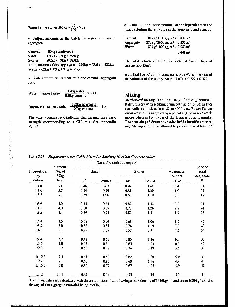
52
1.5 Water in the stones 592kg x E= 9kg
4 Adjust amounts in the batch for water contents in aggregate.
Cement HlOkg (unaltered) Sand 311kg- 12kg= 299kg Stones 592kg - 9kg = 583kg Total amount of dry aggregate = 299kg + 583kg = 882kg Water = 62kg + 12kg + 9kg = 83kg
5 Calculate water - cement ratio and cement - aggregate ratio.
Water - cement ratio q
83kg water = o 83 IOOkg cement .
Aggregate - cement ratio = 882kg aggregate = 8 8 IOOkg cement .
The water - cement ratio indicates that the mix has a basic strength corresponding to a Cl0 mix. See Appendix v: l-2.
6 Calculate the “solid volume” of the ingredients in the mix, excluding the air voids in the aggregate and cement.
Cement lOOkg/ 3’1OOkg/ m3 = 0.032m3 Aggregate 882kg/ 2650kg/ m3 = 0.333m’ Water 83kg/ lOOOkg/m3 = 0.083mJ
0.448m3
The total volume of 1:3:5 mix obtained from 2 bags of cement is 0.45m3.
Note that the 0.45m3 of concrete is only z/3 of the sum of the volumes of the components - 0.074 + 0.222 + 0.370.
Mixing Mechanical mixing is the best way of mixil,& concrete. Batch mixers with a tilting drum for use on building sites are available in sizes from 85 to 400 litres. Power for the drum rotation is supplied by a petrol engine or an electric motor whereas the tilting of the drum is done manually. The pear-shaped drum has blades inside for efficient mix- ing. Mixing should be allowed to proceed for at least 2.5
Table 3.13 Requirements per Cubic Metre for Batching Nominal Concrete Mixes
Naturally moist aggregate’ Cement
Proportions No. of Sand- Stones
by 50kg Volume bags m3 tonnes m3 tonnes
I :4:8 3.1 0.46 0.67 0.92 1.48 1:4:6 3.7 0.54 0.79 0.81 1.30 I :5:5 3.7 0.69 1.00 0.69 1.10
Aggregate: cement
ratio
13.4 11.0 10.9
Sand to total
aggregate
%
31 37 47
1:3:6 4.0 0.44 0.64 0.89 I .42 10.0 31 I :4:5 4.0 0.60 0.87 0.75 1.20 9.9 41 1:3:5 4.4 0.49 0.71 0.82 1.31 8.9 35
I:414 4.5 0.66 0.96 0.66 I .06 8.7 47
1:3:4 5.0 0.56 0.81 0.74 1.19 7.7 40 1:4:3 5.1 0.75 1.09 0.57 0.91 7.6 54
I :2:4 5.7 0.42 0.62 0.85 1.36 6.7 31 1:3:3 5.8 0.65 0.94 0.65 1.03 6.5 47 I:23 6.7 0.50 0.72 0.74 1.19 5.5 37
1:1:5:3 7.3 0.41 0.59 0.82 1.30 5.0 31 1:2:2 8.1 0.60 0.87 0.60 0.96 4.4 47 1:1:5:2 9.0 0.50 0.72 0.67 1.36 3.9 40
1:1:2 10.1 0.37 0.54 0.75 1.19 3.3 31
These quantities are calculated with the assumption of sand having a bulk density of 1450kg/ rn3 and stone 16OOkg/ m3. The density of the aggregate material being 2650kg/ m3.
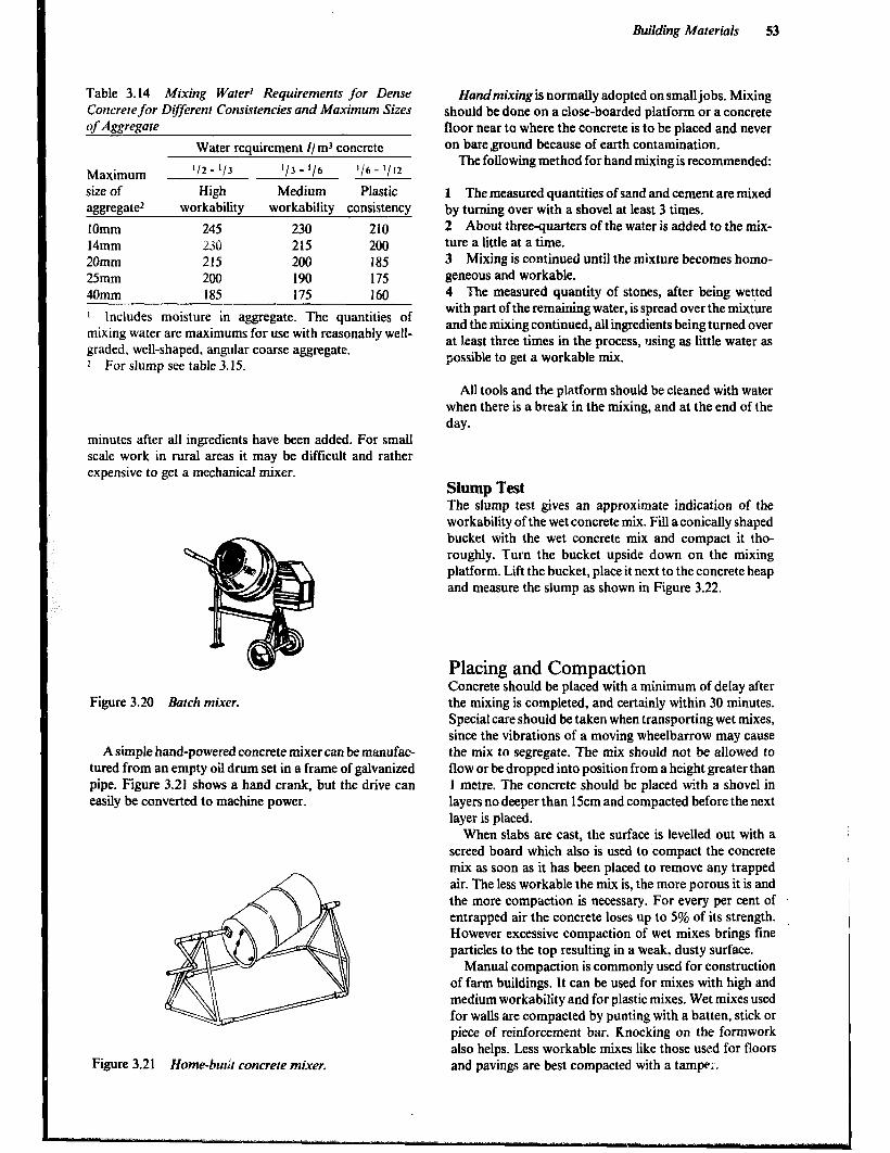
Building Materials 53
Table 3.14 Mixing Wafer’ Requirements for Dense Concrete for D$ferenl Consistencies and Maximum Sizes q f Aggregate
Water requirement I/ m3 concrete
Maximum ‘12 - ‘/3 ‘13 - ‘16 ‘/6 - ‘/ I2
size of High Medium Plastic aggregate2 workability workability consistency
IOmm 245 230 210 14mm 2.X 215 200 20mm 215 200 185 25mm 200 190 175 40mm 185 175 160
1 Includes moisture in aggregate. The quantities of mixing water are maximums for use with reasonably well- graded, well-shaped, angular coarse aggregate. 2 For slump see table 3.15.
Handmixingis normally adopted on small jobs. Mixing should be done on a close-boarded platform or a concrete floor near to where the concrete is to be placed and never on bare ground because of earth contamination.
The folIowing method for hand mixing is recommended:
1 The measured quantities of sand and cement are mixed by turning over with a shovel at least 3 times. 2 About three-quarters of the water is added to the mix- ture a little at a time. 3 Mixing is continued until the mixture becomes homo- geneous and workable. 4 The measured quantity of stones,. after being wetted with part of the remaining water, is spread over the mixture and the mixing continued, all ingredients being turned over at l.east three times in the process, using as little water as possible to get a workable mix.
All tools and the platform should be cleaned with water when there is a break in the mixing, and at the end of the day.
minutes after all ingredients have been added. For small scale work in rural areas it may be difficult and rather expensive to get a mechanical mixer.
Figure 3.20 Batch mixer.
A simple hand-powered concrete mixer can be manufac- tured from an empty oil drum set in a frame of galvanized pipe. Figure 3.21 shows a hand crank, but the drive can easily be converted to machine power.
Figure 3.21 Home-b& concrete mixer.
Slump Test The slump test gives an approximate indication of the workability of the wet concrete mix. Fill aconically shaped bucket with the wet concrete mix and compact it tho- roughly. Turn the bucket upside down on the mixing platform. Lift the bucket, place it next to the concrete heap and measure the slump as shown in Figure 3.22.
Placing and Compaction Concrete should be placed with a minimum of delay after the mixing is completed, and certainly within 30 minutes. Special care should be taken when transporting wet mixes, since the vibrations of a moving wheelbarrow may cause the mix to segregate. The mix should not be allowed to flow or be dropped into position from a height greater than 1 metre. The concrete should be placed with a shovel in layers no deeper than 15cm and compacted before the next layer is placed.
When slabs are cast, the surface is levelled out with a screed board which also is used to .compact the concrete mix as soon as it has been placed to remove any trapped air. The less workable the mix is, the more porous it is and the more compaction is necessary. For every per cent of entrapped air the concrete loses up to 5% of its strength. However excessive compaction of wet mixes brings fine particles to the top resulting in a weak, dusty surface.
Manual compaction is commonly used for construction of farm buildings, It can be used for mixes with high and medium workability and for plastic mixes. Wet mixes used for walls are compacted by punting with a batten, stick or piece of reinforcement bar. Knocking on the formwork also helps. Less workable mixes like those used for floors and pavings are best compacted with a tamppi.

1 1‘1 I
’ 200 4 ---+
Bucket Too wet suitable loo dry .
Figure 3.22 Concrete slump teset.
Table 3. I5 Concrete Slump for Various Uses
Method of
Consistency Slump Use compaction
High l/2 - l/3 Constructions with narrow passages and/or complex shapes. Heavily Manual workability reinforced concrete.
Medium workability
l/3 - l/6 All normal uses. Non-reinforced and normally reinforced concrete. Manual
Plastic r/6 - l/12 Open structures with fairly open reinforcement, which are heavily worked Manual or manually for compaction like floors and pavings. Mass concrete. Mechanical
Stiff 0 - 1112 Non-reinforced or sparsely reinforced open structures like floors and pavings Mechanical which are mechanically vibrate:d. Factory pr? iabrication of concrete goods. Concrete blocks.
Damp 0 Factory prefabrication of the concrete goods. Mechanical or Pressure
Figure 3.23 Manual compaction offoundation andjloor slab.
The stiffer mixes can be thoroughly compacted only with mechanical vibrators. For walls and foundations a poker vibrator (a vibrating pole) is immersed in the placed concrete mix at points up to 50cm apart. Floors and pav- ings are vibrated with a beam vibrator. Figure 3.24 Mechanical vibrators.
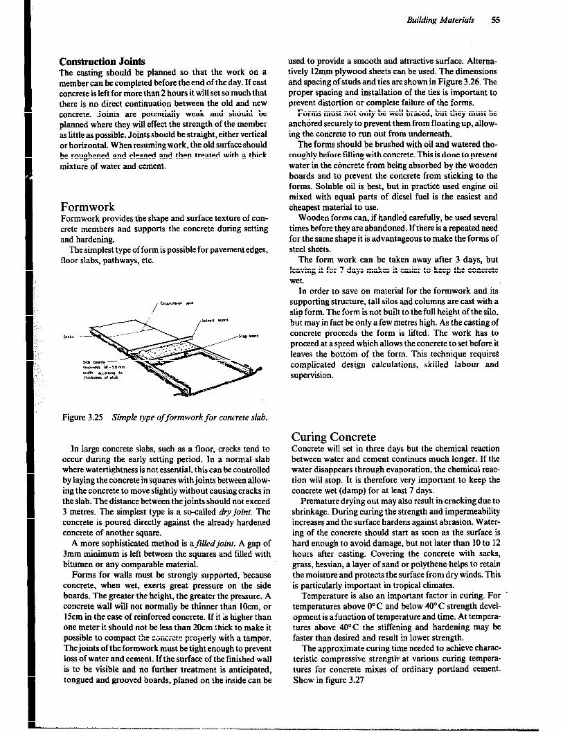
Building Material 55
Construction Joints The casting should be planned so that the work on a member can be completed before the end of the day. If cast concrete is left for more than 2 hours it will set so much that there is no direct continuation between the old and new concrete. Joints are potentially weak and should be planned where they will effect the strength of the member as little as possible. Joints should be straight, either vertical or horizontal. When resuming work, the old surface should be roughened and cleaned and then treated with a thick mixture of water and cement.
Formwork Formwork provides the shape and surface texture of con- crete members and supports the concrete during setting and hardening.
The simplest type of form is possible for pavement edges, floor slabs, pathways, etc.
Figure 3.25 Simple type offormwork for concrete slab.
In large concrete slabs, such as a floor, cracks tend to occur during the early setting period. In a normal slab where watertightness is not essential, this can be controlled by laying the concrete in squares with joints between allow- ing the concrete to move slightly without causing cracks in the slab. The distance between the joints should not exceed 3 metres. The simplest type is a so-called dry joint. The concrete is poured directly against the already hardened concrete of another square.
A more sophisticated method is afilledjoint. A gap of 3mm minimum is left between the squares and filled with bitumen or any comparable material.
Forms for walls must be strongly supported, because concrete, when wet, exerts great pressure on the side boards. The greater the height, the greater the pressure. A concrete wall wilI not normally be thinner than lOcm, or l5cm in the case of reinforced concrete, If it is higher than one meter it should not be less than 20cm thick to make it possible to compact the Zsncrct++ properly with a tamper. The joints of the formwork must be tight enough to prevent loss of water and cement. If the surface of the finished wall is to be visible and no further treatment is anticipated, tongued and grooved boards, planed on the inside can be
used to provide a smooth and attractive surface. Alterna- tively 12mm plywood sheets can be used. The dimensions and spacing of studs and ties are shown in Figure 3.26. The proper spacing and installation of the ties is important to prevent distortion or complete failure of the forms.
Forms must not only be well braced, but they must be anchored securely to prevent them from floating up, allow- ing the concrete to run out from underneath.
The forms should be brushed with oil and watered tho- roughly before filling with concrete. This is done to prevent water in the concrete from being absorbed by the wooden boards and to prevent the concrete from sticking to the forms. Soluble oil is best, but in practice used engine oil mixed with equal parts of diesel fuel is the easiest and cheapest material to use.
Wooden forms can, if handled carefully, be used several times before they are abandoned. If there is a repeated need for the same shape it is advantageous to make the forms of steel sheets.
The form work can be taken away after 3 days, but leaving it for 7 days makes it easier to keep the concrete wet.
In order to save on material for the formwork and its supporting structure, talI silos and columns are cast with a slip form. The form is not built to the full height of the silo, but may in fact be only a-few metres high. As the casting of concrete proceeds the form is lifted. The work has to proceed at a speed which allows the concrete to set before it leaves the bottom of the form. This technique requires complicated design calculations, skilled labour and supervision.
Curing Concrete Concrete will set in three days but the chemical reaction between water and cement continues much longer. If the water disappears through evaporation, the chemical reac- tion will stop. It is therefore very important to keep the concrete wet (damp) for at least 7 days.
Premature drying out may also result in cracking due to shrinkage. During curing the strength and impermeability increases and the surface hardens against abrasion. Water- ing of the concrete should start as soon as the surface is hard enough to avoid damage, but not later than IO to 12 hours after casting. Covering the concrete with sacks, grass, hessian, a layer of sand or polythene helps to retain the moisture and protects the surface from dry winds. This is particularly important in tropical climates.
Temperature is also an important factor in curing. For ’ temperatures above O” C and below 40” C strength devel- opment is a function of temperature and time. At tempera- tures above 40°C the stiffening and hardening may be faster than desired and result in lower strength.
The approximate curing time needed to achieve charac- teristic compressive strength at various curing tempera- tures for concrete mixes of ordinary portland cement. Show in figure 3.27
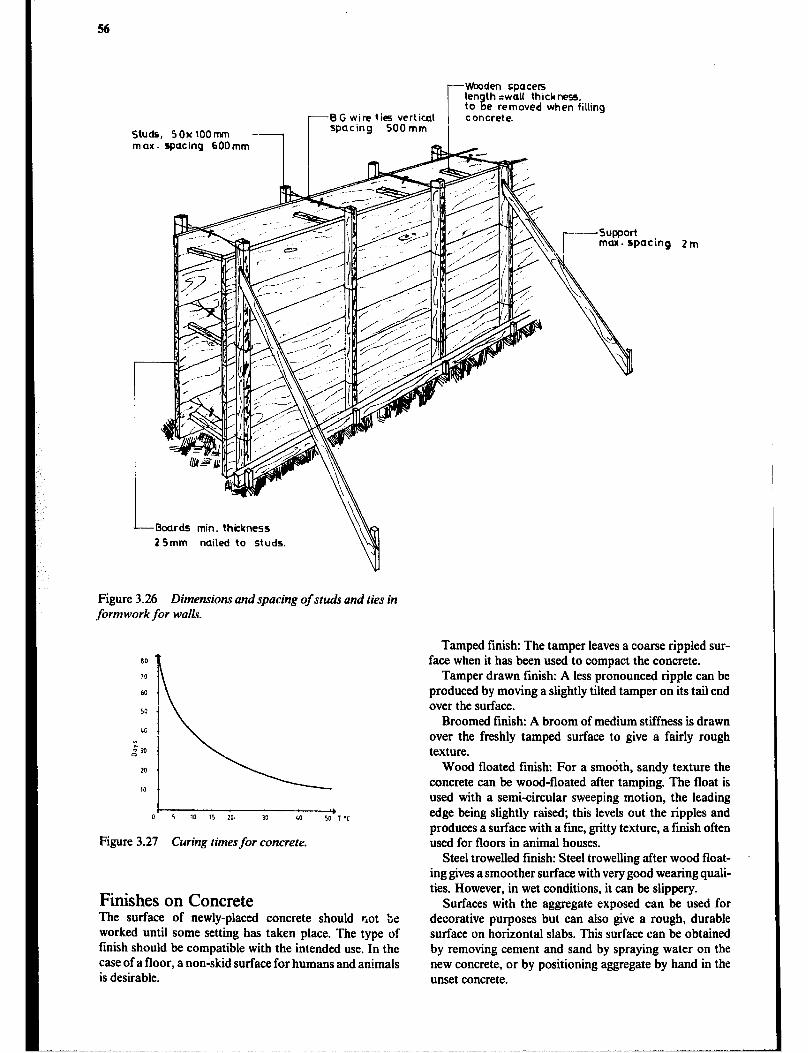
studs, 5ox1oomm - max. spacing 600 mm
-8G wire ties vertical spacing 500 mm
Wooden spaces len to B
th =wall thickness., e removed when filling
concrete.
J---bards min. thickness
2 Smm nailed to studs.
Figure 3.26 Dimensions and spacing of studs and ties in formwork for walls.
80
70
60
50
40
FL 0””
20
10
I Y
5 10 15 20. 30 40 50 T ‘C
Figure 3.27 Curing times for concrete.
Finishes on Concrete The surface of newly-placed concrete should r,ot be worked until some setting has taken place. The type of finish should be compatible with the intended use. In the case of a floor, a non-skid surface for humans and animals is desirable.
cing Zm
Tamped finish: The tamper leaves a coarse rippled sur- face when it has been used to compact the concrete.
Tamper drawn finish: A less pronounced ripple can be produced by moving a slightly tilted tamper on its tail end over the surface.
Broomed finish: A broom of medium stiffness is drawn over the freshly tamped surface to give a fairly rough texture.
Wood floated finish: For a smodth, sandy texture the concrete can be wood-floated after tamping. The float is used with a semi-circular sweeping motion, the leading edge being slightly raised; this levels out the ripples and produces a surface with a fine, gritty texture, a finish often used for floors in animal houses.
Steel trowelled finish: Steel trowelIing after wood float- ing gives a smoother surface with very good wearing quali- ties. However, in wet conditions, it can be slippery.
Surfaces with the aggregate exposed can be used for decorative purposes but can also give a rough, durable surface on horizontal slabs. This surface can be obtained by removing cement and sand by spraying water on the new concrete, or by positioning aggregate by hand in the unset concrete.

Building Materials 51
Reinforced Concrete Concrete is strong in compression but relatively weak in tension. The underside of a loaded beam, such as a lintel over a door, is in tension.
Figure 3.28 Stresses in a concrete lintel.
Concrete subject to tension loading must be reinforced with steel bars or mesh. The amount and type of rein- forcement should be carefully calculated or alternatively, a standard design obtained from a reliable source should be followed without variation.
Important factors relative to reinforced concrete:
1 The steel bars should be cleaned of rust and dirt before they are placed. 2 In order to obtain good adhesion between the concrete and the steel bars, the bars should be overlapped where they join by at least forty times the diameter. When plain bars are used the ends of the bars must be hooked. 3 The reinforcement bars should be tied together well and supported so they won’t move when concrete is placed and compacted. 4 The steel bars must be in the tensile zone and covered with concrete to a thickness of three times the diameter or by at least 25mm to protect them from water and air which causes rusting. 5 The concrete must be well compacted around the bars. 6 Concrete should be at least C20 or 1:2:4 nominal mix and have a maximum aggregate size of 20mm.
Concrete floors are sometimes reinforced with welded steel mesh or chicken wire, placed 25mm from the upper surface of the concrete, to limit the size of any cracking. However, such load-distributing reinforcement is neces- sary only when loadings are heavy, the underlying soil is not dependable, or when cracking must be minimized as in water tanks.
Figure 3.29 Placing reinforcement bars.
Concrete Blocks - Sand-Cement Blocks It is faster to build with concrete blocks than with bricks and the amount of mortar is reduced to less than half. If face shell bedding is used, in which the mortar is placed only along the edges of the blocks, the consumption of mortar is reduced by a further 50%. However, the total cement required for the blocks and mortar is far greater than that required for the mortar in a brick wall.
Concrete blocks are often made of 1:3:6 concrete with a maximum size aggregate of IOmm or a cement-sand mix- ture with a ratio of 1:7, I:8 or 1:9. These mixtures, if properly cured, give concrete blocks a compression strength well above what is required in a one-storey build- ing. The blocks may be solid, cellular or hollow. Cellular blocks have cavities with one end closed while in hollow blocks the cavities pass through. Lightweight aggregate such as cracked pumice stpne is sometimes used.
Blocks are made to a number of coordinating sizes, the actual sizes being about 1Omm less to allow for the thick- ness of the mortar.
Block Manufacturing Blocks can be made by using a-simple block-making machine operated by an engine or by hand. They can also be made by using simple wooden moulds on a platform or floor. The mould can be lined with flat steel plates to prevent damage during tamping and to reduce wear on the mould. In large-scale production steel moulds are often used. The wooden mould is initially oiled overnight and need not be oiled each time it is filled. It is sufficient to wipe it clean with a cloth. The concrete, of stiff or plastic consis- tency, is placed in the mould in layers and each layer is compacted with a 3kg rammer.
The mould in Figure 3.30 has a lid made so that it can pass through the rest of the mouid. The slightly tapered sides can be removed by lifting the handles while holding down the lid with one foot.
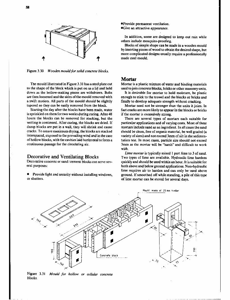
Figure 3.30 Wooden mouldfor solid concrete blocks.
The mould illustrated in Figure 3.3 1 has a steel plate cut to the shape of the block which is put on as a lid and held down as the hollow-making pieces are withdrawn. Bolts are then loosened and the sides of the mould removed with a swift motion. All parts of the mould should be slightly tapered so they can be easily removed from the block.
Starting the day after the blocks have been made, water is sprinkled on them for two weeks during curing. After 48 hours the blocks can be removed for stacking, but the wetting is continued. After curing, the blocks are dried. If damp blocks are put in a wall, they will shrink and cause cracks. To assure maximum drying, the blocks are stacked interspaced, exposed to the prevailing wind and in the case of hollow blocks, with the cavities laid horizontal to form a continuous passage for the circulating air.
Decorative and Ventilating Blocks Decorative concrete or sand /cement blocks can serve sev- eral purposes:
0 Provide light and security without installing windows, or shutters.
l Provide permanent ventilation, @Give an attractive appearance.
In addition, some are designed to keep out ram while others include mosquito-proofing.
Blocks of simple shape can be made in a wooden mould by inserting pieces of wood to obtain the desired shape, but more complicated designs usually require a professionally made steel mould.
Mortar Mortar is a plastic mixture of water and binding materials used to join concrete blocks, bricks or other masonry units.
It is desirable for mortar to hold moisture, be plastic enough to stick to the trowel and the blocks or bricks and finally to develop adequate strength without cracking.
Mortar need not be stronger than the units it joins. In fact cracks are more likely to appear in the blocks or bricks if the mortar is excessively strong.
There are several types of mortars each suitable for particular applications and of varying costs. Most of these mortars include sand as an ingredient. In all cases the sand should be clean, free of organic material, be well graded (a variety of sizes) and not exceed 3mm of silt in the sedimen- tation test. In most cases, particle size should not exceed 3mm as the mortar will be “harsh” and difficult to work with.
Lime mortar is typically mixed 1 part lime to 3 of sand. Two types of lime are available. Hydraulic lime hardens quickly and should be used within an hour. It is suitable for both above and below ground applications. Non-hydraulic lime requires air to harden and can only be used above ground. If smoothed off while standing, a pile of this type of lime mortar can be stored for several days.
Hould made of 25mm ttmtier
Figure 3.31 Mould for hollow or cellular concrete blocks.
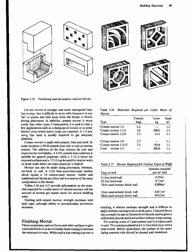
Building Materials 59
Figure 3.32 Ventilating and decorative concrete blocks.
Cen.ent mortar is stronger and more waterproof than line mortar, but is difficult to work with because it is not ‘fat’ or plastic and falls away from the blocks or bricks during placement. In addition, cement mortar is more costly l:han other types. Consequently it is used in only a few applications such as a damp-proof course or in some limited areas where heavy loads are expected. A I:3 mix us& fine sand is usually required to get adequate plasticity.
Compo mortar is made with cement, lime and sand. In some localities a 50:50 cement-lime mix is sold as mortar cement. The addition of the lime reduces the cost and improves the workability. A 1:2:9, cement-lime-sand mix is suitable for general purposes, while a 1:1:6 is better for exposed surfaces and a 1:3: 12 can be used for interior walls or stone walls where the extra plasticity is helpful.
Mortar can also be made using pouolana, bitumen, cut-back or soil. A 1:2:9 lime-pouolana-sand mortar about equals a 1% cement-sand mortar. Adobe and stabilized-soil blocks are often laid in a mortar of the same composition as the blocks.
Tables 3.16 and 3.17 provide information on the mate- rials required for a cubic metre of various mortars and the amount of mortar per square meter for several building UUitS.
Starting with cement mortar, strength decreases with each type, although ability to accommodate movement increases.
Finishing Mortar Thii is sometimes used on floors and other surfaces to give a smooth finish or as an extremely hard coating to increase the resistance to wear. While such a top coating is prone to
Table 3.16 Materials Required per Cubic Meter of Mortar
Cement Lime Sand
Type bags kg m3
Cement mortar I:5 6.0 - 1.1 Compo mortar 1: 1:6 5.0 100.0 1.1 Compo mortar 1:2:9 3.3 13.5 1.1
Compo mortar I:8 3.7 - 1.1 Compo mortar I :3: 12 2.5 150.0 1.1 Lime mortar I:3 - 200.0 1.1
Table 3.17 Mortar Requiredfor Various Types of Walls
Amount required Type of wall
11.5cm brickwall 22.2cm brickwall 1Ocm sand-cement block wall
15cm sand-cement block wall 20cm sand-cement block wall
per m* wall
0.25m3 0.5im3
0.008m3
0.01 lm3 0.015m3 -
cracking, it seldom increases strength and is difficult to apply without causing loose or weak parts. Concrete floors can normally be cast to finished level directly and be given a sufficiently smooth and hard surface without a top coating.
For coating, a mix of 1 part cement and 2 to 4 parts sand is used. The coating is placed in’s 1 to 2cm thick layer with a steel trowel. Before application, the surface of the under laying concrete slab should be cleaned and moistened.
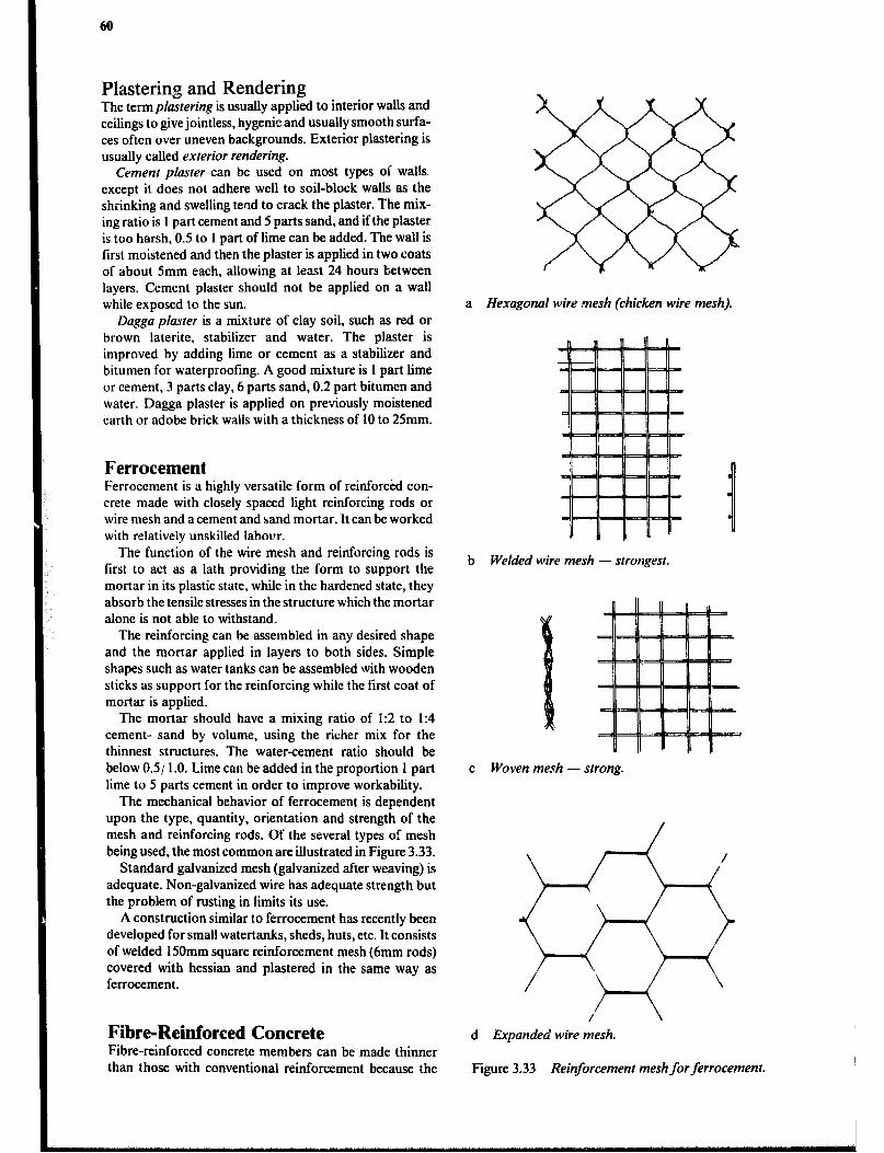
60
Plastering and Rendering ne term plastering is usually applied to interior walls and ceilings to give jointless, hygenic and usually smooth surfa- ces often over uneven backgrounds. Exterior plastering is usually called exterior rendering.
Cement plaster can be used on most types of walls. except it does not adhere well to soil-block walls as the shrinking and swelling tend to crack the plaster. The mix- ing ratio is 1 part cement and 5 parts sand, and if the plaster is too harsh, 0.5 to 1 part of lime can be added. The wall is first moistened and then the plaster is applied in two coats of about Smm each, allowing at least 24 hours between layers. Cement plaster should not be applied on a wall while exposed to the sun.
Dagga plaster is a mixture of clay soil, such as red or brown laterite. stabilizer and water. The plaster is improved by adding lime or cement as a stabilizer and bitumen for waterproofing. A good mixture is 1 part lime or cement, 3 parts clay, 6 parts sand, 0.2 part bitumen and water. Dagga plaster is applied on previously moistened earth or adobe brick walls with a thickness of 10 to 25mm.
Ferrocement Ferrocement is a highly versatile form of reinforced con- crete made with closely spaced light reinforcing rods or wire mesh and a cement and sand mortar. It can be worked with relatively unskilled labour.
The function of the wire mesh and reinforcing rods is first to act as a lath providing the form to support the mortar in its plastic state, while in the hardened state, they absorb the tensile stresses in the structure which the mortar alone is not able to withstand.
The reinforcing can be assembled in any desired shape and the mortar applied in layers to both sides. Simple shapes such as water tanks can be assembled with wooden sticks as support for the reinforcing while the first coat of mortar is applied.
The mortar should have a mixing ratio of 1:2 to I:4 cement- sand by volume, using the richer mix for the thinnest structures. The water-cement ratio should be below 0.5/ 1.0. Lime can be added in the proportion 1 part lime to 5 parts cement in order to improve workability.
The mechanical behavior of ferrocement is dependent upon the type, quantity, orientation and strength of the mesh and reinforcing rods. Of the several types of mesh being used, the most common are illustrated in Figure 3.33.
Standard galvanized mesh (galvanized after weaving) is adequate. Non-galvanized wire has adequate strength but the problem of rusting in limits its use.
A construction similar to ferrocement has recently been developed for small watertanks, sheds, huts, etc. It consists of welded 150mm square reinforcement mesh (6mm rods) covered with hessian and plastered in the same way as fenocement.
Fib-Reinforced Concrete Fibre-reinforced concrete members can be made thinner than those with conventional reinforcement because the
a Hexagonal wire mesh (chicken wire mesh).
b Welded wire mesh - strongest.
c Woven mesh - strong.
d Expanded wire mesh.
Figure 3.33 Reinforcement mesh for ferrocement.

Building Mareriah 61
corrosion- protective cover over the steel bars is not neces- sary. The fibres improve flexible strength and resistance to cracking.
Commonly used fibres are asbestos, steel (0.2Smm diameter), sisal, elephant grass, etc.
Asbestos Cement (A-C) Asbestos, a silicate of magnesium, occurrs as a rock which can bc split into extremely thin Gbres from 2 to 900mm long. These have good resistance to alkalis, neutral salts and organic solvents, and the varieties used for building products have good resistance to acids. Asbestos is non- combustible and able to withstand high temperatures without change.
Inhalation of dust causes asbestosis (a disease of the lungs) and asbestos is now used only where no alternative fibre is available. Workers must wear masks and use great care not to inhale any asbestos dust!
The fibres being strong in tension and flexible, are used as reinforcement with portland cement, lime and bitumeri binders, in asbestos-cement and asbestos-silica- lime pro- ducts, vinyl floor tiles and in bitumen felts. Asbestos- cement is used in farm structures for corrugated roofing sheets, ridges and sanitary pipes.
Sisal-Fibre-Reinforced Cement (SFRC) Sisal and other vegetable fibres have only recently come intc use for reinforcement of concrete.
Sisal tibre can be used as short, discontinuous fibres (15 to 7Smm in length) or as continuous long fibres over 7Smm in length. Sometimes both short and long fibres are used together. The manner in which the fibres arr incorporated into the matrix affects the properties of the composite both in the fresh state as well as in the hardened state.
Sisal fibres may deteriorate if not treated. Although the alkalinity of the concrete helps to protect the fibres from outside attack, it may itself attack the fibres chemically by decomposing the lignin.
Sisal-fibre reinforcing is used with various cement-sand mixing ratios, depending on the use:
wall plastering 1:3 guttering 1:2 roofiig tiles 1:l corrugated roofing sheets 1:0.5
The sand should be passed through a sieve with 1 .Smm to 2mm holes (e.g., mosquito netting). The mixing water must be pure and the mix kept as dry as possible while still being workable.
Between 16g and 17g of short (25mm) dry sisal fibres are added to the mix for each kilogramme of cement. The short libres are mixed into the dry cement and sand before adding water. Sisal fibres have a high water absorption, and some extra water may have to be added to the mix to compensate for this.
When mixing there is a tendency for the fibres to ball and separate out from the rest of the mix. This tendency will increase with longer fibres, but if fibres shorter than 2Smm are used the reinforcing effect will be reduced. In most cases, the mix is then trowelled on to a mesh of full-length sisal fibres.
Making Corrugated Reinforced Roofing Sheets Homemade reinforced corrugated roofing is usually cast to standard width, but only one metre :ong because of its additional weight. Commercial asbestos-cement roofing is heavier than corrugate steel and the home made sheets are still heavier. Thus special attention must be given to rafter or truss sizes to ensure a safe structure.
The casting procedure for SFRC is involved, but once the proper equipment has been assembled and several sheets have been made the process becomes much easier.
A concrete block cast over a Im length of asbestos- cement roofing is needed as a face for the casting of the roof sheets. The block is cast within a form, 1OOmm high, which will give a block of sufficient strength after a few days curing. Two or more Im lengths of A-C roofing will be needed as well as a piece of 18mm plywood 1.2m by 1.2m and a sheet of heavy duty polythene 2.25m long and lm wide. The polythene is folded in the middle and a thin batten 9mm by 1Smm is stapled fast at the fold. Strips of 9mm plywood or wood are nailed along two edges of the plywood sheet leaving exactly lm between them as shown in Figure 3.34.
Following are the steps in the casting procedure:
1 Fit an asbestos cement sheet on to the moulding block and cover with the piece of plywood with the edge strips at the ends of the sheet. The polythene is placed over the plywood and the top sheet folded back off the plywood. 2 Prepare a mix of 9kg cement, 4.5kg sand, 150g short sisal !ibres (25mm) and 4.5 litres of water. Also prepare four 60g bundles of sisal fibres, as long as possible. 3 Use one-third of the mortar mix to trowel a thin even layer over the polythene. Take two of the four sisal bundles and distribute the fibres evenly, the second bundle at right angles to the first, forming a mat of fibres. This is covered with mortar and another mat, using the remaining two bundles. Finally all the sisal is covered with the remaining mortar, and the surface screeded even with the edge strips on the plywood. 4 Cover with the top sheet of polythene, ensuring that the mortar is of even thickness all over and that no air bubbles remain under the polythene. 5 While holding the batten strip at the fold in the poly- thene, carefully remove the plywood sheet to allow the new sisal-cement sheet to fall onto the asbestos-cement sheet. At the same time press the new sheet into the corrugations using a PVC drain pipe of 90mm diameter. Compact the new sheet by placing another asbestos sheet on top and treading on it. Holes for mounting are punched with a 5mm dowel 2Smm from the endid the gulleys (crests when mounted on the roof) of the fresh sheet.

62
PVC -Pipe
‘, \\ ,- h
‘d
Figure 3.34 Plywood casring board andpolythene “envelope”.
6 Remove the asbestos sheet bearing the sisal-cement sheet from the moulding block and leave it until the cement in the new sheet has set, preferably two days. Then care- fully remove the new sheet, peel off the polythene and cure the new sheet for at least one week, preferably immersed in a water tank. 7 If more polythene and asbestos-cement sheets are available, casting can proceed immediately.
Walls Using Sisal-Cement Plastering Technique Soil blocks can be used for inexpensive walls with good thermal insulation. However, they are easily damaged by impact and eroded by rain. One way of solving these problems is to plaster the face of the wall. Ordinarily mortar plaster tends to crack and peel off as it does not expand at the same rate as the soil. This can be overcome by letting long sisal fibres pass through the wall to be incorporated into the mortar on each face. The double skin so formed provides sufficient strength and waterproofing to the wall to enable soil blocks to be laid without joining mortar between the blocks.
xntaining sisal f i bres
t I J.7
Soil block
per kg cement
Figure 3.35 Sisal-cement plastering technique.
Metals Several ferrous metals (those containing iron) are useful in farm building construction. Cast iron is used for making sanitary waste pipe and fittings. Steel consists of iron plus a small percentage of carbon in chemical combination. High-carbon or hard steel is used for tools with cutting edges. Medium-carbon steel is used for structural members such as “I” beams, reinforcing bars and implement framts. Low-carbon or mild steel is used for pipe, nails, screws, wire, screening, fencing and corrugated roof sheets.
Non-ferrous metals such as aluminium and copper are corrosion resistant and are often chosen on that account. Copper is used for electric wire, tubing for water supply and for flashing. Aluminium is most commonly used for corrugated rooting sheets, gutters and the accompanying nails. Using nails of the same material avoids the problem of corrosion due to electrolytic action. Brass is a corrosion resistant alloy of copper and zinc which is used extensively for building hardware.
Corrosion Air and moisture accelerate corrosion in ferrous materials unless they are protected. Acids tend to corrode copper while alkalies such as found in animal waste, Portland cement and lime, as well as some soils, will cause rapid corrosion of aluminium and zinc. Electrolytic action caused by slight voltages set up when dissimilar metals are in contact with each other in the presence of water also encourages corrosion in some metals. Aluminium is par- ticularly subject to electrolytic corrosion.
Corrosion can be reduced by carefully selecting metal products for the application; reducing the time that the metal will be wet by preventing condensation and promot- ing good drainage, avoiding contact between dissimilar metals, and by using corrosion-inhibiting coatings.
Corrosion Inhibiting Coatings Copper, aluminium, stainless steels and cast iron tend to form oxide coatings that provide a considerable amount of
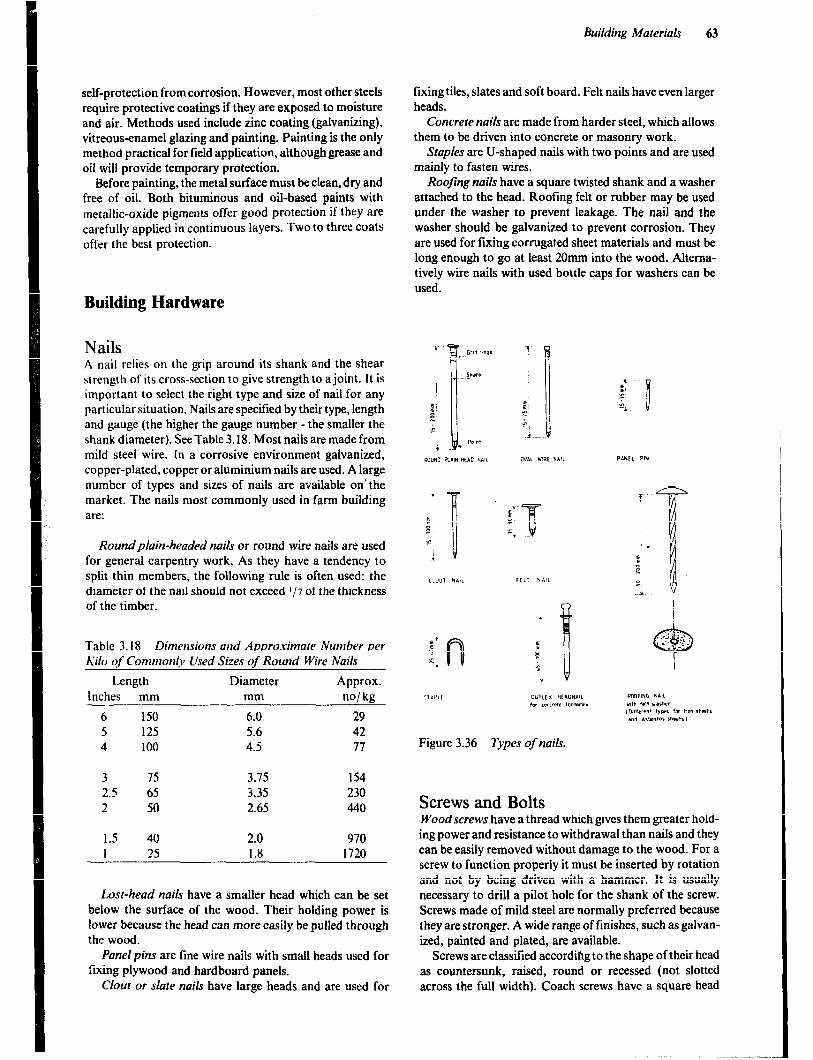
self-protection from corrosion. However, most other steels require protective coatings if they are exposed to moisture and air. Methods used include zinc coating (galvanizing), vitreous-enamel glazing and painting. Painting is the only method practical for field application, although grease and oil will provide temporary protection.
Before painting, the metal surface must be clean, dry and free of oil. Both bituminous and oil-based paints with metallic-oxide pigments offer good protection if they are carefully applied in continuous layers. TWO to three coats
offer the best protection.
Building Hardware
Nails A nail relies on the grip around its shank and the shear strength of its cross-section to give strength to a joint. It is important to select the right type and size of nail for any particular situation. Nails are specified by their type, length and gauge (the higher the gauge number - the smaller the shank diameter). See Table 3.18. Most nails are made from mild steel wire. In a corrosive environment galvanized, copper-plated, copper or aluminium nails are used. A large number of types and sizes of nails are available on’the market. The nails most commonly used in farm building are:
Roundplain-headed nails or round wire nails are used for general carpentry work. As they have a tendency to split thin members, the following rule is often used: the diameter of the nail should not exceed l/7 of the thickness of the timber.
Table 3.18 Dimensions and Approximate Number per Kilo of Cotntttoniy Used Sizes of Round Wire Nails
Length Diameter Approx. Inches mm mm no/kg
6 150 6.0 29 5 125 5.6 42 4 loo 4.5 77
3 75 3.75 154 2.5 65 3.35 230 2 50 2.65 440
1.5 40 2.0 970 I 25 1.8 1720
Losl-head nails have a smaller head which can be set below the surface of the wood. Their holding power is lower because the head can more easily be pulled through the wood.
Panelpins are line wire nails with small heads used for fixing plywood and hardboard panels.
Clour or slate nails have large heads and are used for
Building Materials 63
fixing tiles, slates and soft board. Felt nails have even larger heads.
Concrere nails are made from harder steel, which allows them to be driven into concrete or masonry work.
Staples are U-shaped nails with two points and are used mainly to fasten wires.
Roofing nails have a square twisted shank and a washer attached to the head. Roofing felt or rubber may be used under the washer to prevent leakage. The nail and the washer should be galvanized to prevent corrosion. They are used for fixing corrugated sheet materials and must be long enough to go at least 20mm into the wood. Alterna- tively wire nails with used bottle caps for washers can be used.
1
s F c
i “I
Figure 3.36 Types of nails.
Screws and Bolts Woodscrews have a thread which gives them greater hold- ing power and resistance to withdrawal than nails and they can be easily removed without damage to the wood. For a screw to function properly it must be inserted by rotation and not by being driven with a hammer. It is usually necessary to drill a pilot hole for the shank of the screw. Screws made of mild steel are normally preferred because they are stronger. A wide range of finishes, such as galvan- ized, painted and plated, are available.
Screws are classified accordihg to the shape of their head as countersunk, raised, round or recessed (not slotted across the full width). Coach screws have a square head
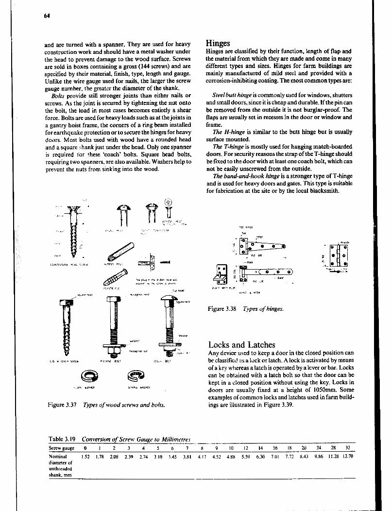
64
and are turned with a spanner. They are used for heavy construction work and should have a metal washer under the head to prevent damage to the wood surface. Screws are sold in boxes containing a gross (144 screws) and are specified by their material, finish, type, length and gauge. Unlike the wire gauge used for nails, the larger the screw gauge number, the g.,aLbX r,= +*- the diameter of the shank.
Bolts provide still stronger joints than either nails or screws. As the joint is secured by tightening the nut onto the bolt, the load in most cases becomes entirely a shear force. Bolts are used for heavy loads such as at the joints in a gantry hoist frame, the corners of a ring beam installed for earthquake protection or to secure the hinges for heavy doors. Most bolts used with wood have a rounded head and a square &ank just under the head. Only one spanner is required ior ?hese ‘coach’ bolts. Square head bolts, requiring two spanners, are also available. Washers help to prevent the nuts irom sinking into the wood.
Figure 3.37 Types of wood screws and bolts.
Table 3.19 Conversion of Screw Gauge to Millinttvres
Hinges Hinges are classified by their function, length of flap and the material from which they are made and come in many different types and sizes. Hinges for farm buildings are mainly manufactured of mild steel and provided with a corrosion-inhibiting coating. The most common types are:
Steel butt hinge is commonly used for windows, shutters and small doors, since it is cheap and durable. If the pin can be removed from the outside it is not burglar-proof. The flaps are usually set in recesses in the door or window and frame.
Z%e H-hinge is similar to the butt hinge but is usually surface mounted.
The T-hinge is mostly used for hanging match-boarded doors. For security reasons the strap of the T-hinge should be fixed to the door with at least one coach bolt, which can not be easily unscrewed from the outside.
The band-and-hook hinge is a stronger type of T-hinge and is used for heavy doors and gates. This type is suitable for fabrication at the site or by the local blacksmith.
Figure 3.38 Types of hinges.
Locks and Latches Any device used to keep a door in the closed position can be classified as a lock or latch. A lock is activated by means of a key whereas a latch is operated by a lever or bar. Locks can be obtained with a latch bolt so that the door can be kept in a closed position without using the key. Locks in doors are usually fmed at a height of 1050mm. Some examples of common locks and latches used in farm build- ings are illustrated in Figure 3.39.
Screw gauge 0 I 2 3 4 5 b 7 8 9 10 12 14 16 I8 20 24 28 32 -.- Nominal 1.52 1.78 2.08 2.39 2.74 3.10 3.45 3.81 4.17 4.52 4.88 5.59 6.30 7.01 7.72 8.43 9.86 il.28 12.70 diameter of unthreaded shank, mm
----

Building Materials 65
Figure 3.39 Types of locks and latches.
Glass Glass suitable for general window glazing is made mainly from soda, lime and silica. The ingredients are heated in a furnace to about 1500°C and fuse together in the molten state. Sheets are then formed by a process of drawing, floating or rolling. The ordinary glazing quality is manu- factured by drawing in thicknesses ranging from 2 to 6mm. It is transparent with 90% light transmission. Because the two surfaces are never perfectly flat or parallel there is always some visual distortion. Plate glass is manufactured with ground and polished surfaces and should be free of imperfections.
Glass in buildings is required to resist loads including wind loads, impact by persons and animals and sometimes thermal and other stresses. Generally the thickness must increase with the area of glass pane. Glass is elastic right up to its breaking point, but is also completely brittle so there is no permanent set or warning of impending failure. The support provided for glass will affect its strength perfor- mance. Glass should be cut to give a minimum clearance of 2mm all around the frame to allow for thermal movements.
Plastics Plastics are among the newest building materials, ranging from material strong enough to replace metal to foam-like products. Plastics are considered to be mainly organic materials derived from petroleum and, to a small extent coal, which at some stage in processing are plastic when heated.
The range of properties is so great that generalizations are difficult to make. However, plastics are usually light in weight and have a good strength to weight ratio, but rigid- ity is lower than that of virtually all other building mate- rials, and creep is high.
Plastics have low thermal conductivity and thermal capacity, but thermal movement is high. They resist a wide range of chemicals and do not corrode, but they tend to become brittle with age.
Most plastics are combustible and may release poison- ous gases in a fire. Some are highly flammable, while others are difficult to burn.
Plastics lend themselves to a wide range of manufactur- ing techniques, and products are available in many forms- solid and cellular, from soft and flexible to rigid, from transparent to opaque. Various textures and colours (many of which fade if used out-of-doors) are available. Plastics are classified as:
Rermoplastics which always soften when heated and harden again on cooling, provided they are not overheated.
i%ermosetting plastics which undergo an irreversible chemical change in which the molecular chains crosslink so they cannot subsequently be appreciably softened by heat. Excessive heating causes charring.
Thermoplastics Polythene is tough, water- and oilproof and can be manu-
factured in many colours. In buildings it is used for cold water pipes, plumbing and sanitary ware and polythene film (translucent or black). Film should not be unnecessar- ily subjected to prolonged heat over 50°C or to direct sunlight. The translucent film will last only one to two years exposed to sunlight, but the carbon pigmentation of the black film increases resistance to sunlight.
Polyvinyl chloride (PVC) will not burn and can be made in rigid or flexible form. It is used for rainwater goods, drains, pipes, ducts, electric cable insulation, etc.
Acrylics, a group of plastics containing, polymethyl methacrylate, transmit more light than glass, and can be easily moulded or curved to almost any shape.
Thermosetting Plastics The main use of thermosetting plastics in buildings is as impregnants for paper fabrics, binders for particle boards, adhesives paints and clear finishes . Phenol formaldehyde (bakelite) is used for electrical insulating accessories. Urea- formaldehyde is used for particle board manufacture.
Epoxide resins are, for most uses, provided in two parts, a resin and a curing agent. They are extremely tough and stable and adhere well to most materials. Silicone resins are water repellant and used for waterproofing in masonry. Note that fluid plastics can be very toxic.
Rubber Rubbers are similar to thermosetting plastics. In the manu- facturing process a number of ‘substances are mixed with latex, a natural polymer. Carbon black is added to increase strength in tension and to improve wearing properties.
66
After forming, the product is vulcanised by heating
, under pressure, usually with sulphur present. In this pro- cess the strength and elasticity is increased. Ebonite is a fully vulcanised, hard rubber.
Modified and synthetic rubbers (elastomers) are increas- ingly being used for building products. For example unlike natural rubbers they often have good resistance to oil and solvents. One of them, butyl is extremely tough, has good weather resistance, excellent resistance to acids and a very low permeability to air. Synthetic rubber fillers and nail washers are used with metal roofing.
Bituminous Products These include bitumen (called asphalt in the USA), coal tar and pitch. They are usually dark brown or black and are in general durable materials, resistant to many chemicals. They resist the passage of water and water vapour, espe- cially if they have been applied hot.
Bitumen occurs naturally as rock asphalt or lake asphalt or can be distilled from petroleum. It is used for road paving, paint, damp-proof membranes, joint tiller, stabil- izer in soil blocks, etc.
Paints Paint preserves, protects and decorates surfaces ana cna- bles them to be cleaned easily. All paints contain a binder which hardens. Other ingredients found in various paints include: pigments, strainers, extenders, driers, hatdeners, thinners, solvents and gelling agents. Some water-thinned paints contain emulsifiers.
Because of the cost involved, few buildings in the rural areas are painted. When paint can be afforded priority should be given to surfaces likely to rust, rot or decay because of exposure to rain or dampness and to rooms like a kitchen or a dairy where hygiene demands easily cleaned surfaces. White and other light colours reflect more light than dark colours and can be used in rooms like a sitting room or a workshop to make the room lighter.
Painting Adequate preparation of the surface to be painted is essen- tial. The surface should be smooth (not shiny for this would not give good anchor), clean, dry and stable. Old, loose paint should be brushed off before a new coat is applied. Most commercial paints are supplied with direc- tions for use, which should be read carefully before the work is started. The paint film is usually built up in two or more coats:
Priming paints are used for the first coat to seal and protect the surface and to give a smooth surface for subse- quent coats. They are produced for application to wood, metal and plaster.
Undercoatingpaints are sometimes used to obscure the primer, as a further protective coating and to provide the correct surface for the finishing paint.
Finishing paints arc produced with a wide range of colours and finishes (e.g., matt, semi-matt, gloss). Some commonly used types of paint for farm structures are detailed below, but many others are manufactured with special properties like water and chemical resistance, heat resistance, fire retardant, anti-condensation, fungicidal, insecticidal, etc.
Oil- and Resin-based Paints Oilpaints are based on natural drying oils (e.g., linseed oil). They are being gradually replaced by alkyd and emulsion paints.
Alkydpaints are oil-based paints modified by the addi- tion of synthetic resins to improve durability, flexibility, drying and gloss. They are quite expensive.
Synthetic resinpaints contain substantial proportions of thermosetting resins, such as acrylics, polyurethane or epoxides, and are often packaged in two parts. They have excellent strength, adhesion and durability, but are very expensive.
Bitumenous paints are used to protect steelwork and iron sheeting from rust and wood from decay. They are black or dark in colour and tend to crack in hot sunlight. They can be overpainted with ordinary paint only after a suitable sealer has been applied.
Varnishes are either oil/ resin or spirit-based and mainly used to protect wood with a transparent finish, but protec- tion is inferior compared to opaque finishes. Spirit-based varnish is only used for interior surfaces.
Water-thinned Paints Non-washable distemper consists of chalk powder mixed with animal glue dissolved in hot water. It is cheap but easily rubbed or washed off and therefore only suitable for whitening ceilings.
Washable distemper (water paint) consists of drying oil or casein emulsified in water and additions of pigments and extenders. Hardening is slow but after a month it can withstand moderate scrubbing. It weathers fairly well out- doors and is fairly cheap.
White wash (lime wash) consists of lime mixed with water. It can be used on all types of walls including earth walls and is cheap, but its lack of water resistance and its poor weathering properties make it inferior to emulsion paint for outdoor surfaces. However, an addition of tallow or cement gives some degree of durability for external use. White wash can be made in the following way:
1 Mix 8 litres (9kg) quicklime with about 18 litres boiling water, adding the water slowly and stirring constantly until a thin paste results. 2 Add 2 litres salt and stir thoroughly.

Building Materials 67
3 Add water to bring the white wash to a suitable consistency. 4 If external quality is required add a handful cement per 10 litres white wash just before use.
Emulsion paints have the pigments and binder (vinyl, acrylic, urethane or styrene polymers) dispersed as small globules in water. They harden quickly, are quite tough and weather resistant and of medium cost, They adhere well to most backgrounds, but since they are permeable, an oil-based primer may be required to seal porous exterior surfaces.
Cement-basedpaints are often used for exteriors and are quite inexpensive. They contain white portland cement, pigments if other colours are desired, and water repellents,
and are sold in powder form. Water is added just before use to make a suitable consistency. Paint that has thickened must not be thinned further. It adheres well to brickwork, concrete and renderings but not to timber, metal or paint of other types. Surfaces should be dampened before painting.
Cement slurries make economical surface coatings on masonry and concrete, but earth walls that shrink and swell will cause the coating to peel off. Slurries are mixtures of cement and/ or lime, clean fine sand and enough water to make a thick liquid. A good slurry is made from 1 part cement and 1 part lime and up to 4 parts of sand. It is applied on the dampened surface with a large brush or a used bag, hence the name “bag washing”.
Further Reading Barnes M.M., Farm Construction, Buildings, Slough, Cement and Concrete Association, 1971. Eldridge H.J., Properties of Building Materials, Lancaster, Medical and Technical Publishing Co. Ltd., 1974. Everett A., Materials, Mitchell’s Building Series, London, Batsford Academic and Educational Ltd., 1981. Fullerton R.L., Building Construction in Warm Climates, Part 1-3, Oxford, Oxford University Press, 1977-1979. Hodgkinson A., A.J. Handbook of Building Structure, London, The Architectural Press Ltd., 1982. International Labour Office. Small-Scale Brickmaking, Geneva, International Labour Office, 1984. Lippsmeier G.. Tropenbau-Building in the Tropics, Munchen, Callwey Verlag, 1969. Lundborg N.. To Choose Timber-for Building, Dar-es-Salaam, National Housing and Building Research Unit, 1976. Lunt M.G., Stabilized Soil Blocksfor Building, Overseas Building Notes No. 184, Watford, Building Research Establish-
ment, Overseas Division, 1980. McKay W.B., Carpentry. London, Longman Group Ltd., 1975. National Academy of Science, Ferrocement: Applications in Developing Countries, Washington, D.C., National Academy
of Science, 1973. National Vocational Training Institute, Accra, Rural Building:
1 Reference Book, 2 Basic Knowledge. 3 Construction, 4 Drawing Book, Maastricht, Stichting Kongregatie F.I.C. Paterson D.N., The Strengrh of Kenya Timbers Tkeir Derivation and App!ication, Nairobi, Kenya Forest Department,
1971. Shetty M.S., Concrete Technology. New Delhi, S. Chand & Co. Ltd., 1982. Spence R.J.S., Cook D.J., Building Materials in Developing Countries, Chichester, John Wiley & Sons Ltd., 1983. Storrs A.E.G., Know Your Trees, Ndola, The Forest Department, 1979. Storrs A.E.G., More About Trees, Ndola, The Forest Department, 1982. Stulz R., Appropriate Building Materials, SKAT No. 12, St. Gallen, Swiss Center for Appropriate Technology, 1981. Swift D.G., Smith R.B.L., 17re Construction of Corrugated Roofing Sheets Using Sisal-Cement, Nairobi, Kenyatta
University College. 1979. United Nations, Ttre Use of Bamboo and Reeds in Building Construction, New York, United Nations, 1972. Whitaker J.H., Agricultural Buildings and Structures, Restion, Reston Publishing Co., 1979. VITA, Making Building Blocks with the CINVA - Ram Block Press, Mt. Rainier, Volunteers in Technical Assistance, 1977.
Chapter 4
Structural Design
Introduction .4 structure is designed to perform a certain function. To perform this function satisfactorily it must have sufficient strength and rigidity. Economy, durability and an attrac- tive appearance are also of importance in structural design.
Structures are subjected to a variety of loads either singly or in combination. These include the self-weight of the materials used for construction as well as the weight of products stored, animals housed or water dammed. The short-term loads due to wind and even earthquakes must also be included. The designer must have an understanding of the nature and significance of these forces and apply this knowledge to the design, materials and methods of con- struction if the structure is to safely survive all situations. Each of the various elements, such as ties, struts and beams, has a unique purpose in maintaining the integrity of the structure and must be designed to have sufficient strength to withstand the maximum stress to which it may be subjected.
The many building materials available differ greatly in their resistance to loading and in other characteristics that relate to their use in various building elements. They must be selected carefully to be suitable for the type or types of loading which are determined during the structural design procedure.
The analysis of all farm building structures is based on certain fundamental principles which are addressed in this chapter.
Approximations It is necessary for the designer to fully understand the principles of statics and mechanics of materials as well as the function of structural members. I! is as a result of this understanding that he is able to make assumptions and approximations which enable him to reduce complex situations to a level at which simple design techniques produce adequate, although sometimes over-designed, stmctures.
Design Codes Many countries have their own structural design codes, codes of practice or technical documents which perform a similar function. It is necessary for a designer to become familiar with local requirements or recommendations in regard to correct practice. In this chapter some examples ate given, occasionally in a simplified form, in order to demonstrate procedures. They should not be assumed to apply to all areas or situations.
Basic Principles of Statics Structural engineering is concerned with the strength, stiff- ness and stability of structures such as buildings, dams, bridges and retaining walls. Although a building is con- structed from the foundation upwards, the designer has to start at the top with the roof and work his way downwards. There are two distinct stages in structural design. First the structural engineer with his experience, intuition and knowledge makes an imaginative choice of preliminary design in terms of layout, materials and erection methods. Estimates of the various forms of loading are made and then the chosen design is subjected to detailed analysis based on the principles of statics. Statics is one main branch of mechanics and deals with forces on bodies, which are ‘at rest’ (static equilibrium). The other main branch, dynamics, deals with moving bodies, such as parts of machines.
Static Equilibrium Forces acting in one plane (i.e., coplanar) and in equilibrium must satisfy one of the following sets of conditions:
Y
I 9o”
ZF,=O ZF,=O IF,=0 TM,=0 IF,. = 0 or 1.M. q 0 or IM. = 0 or IMr, = 0
x TM.=0 ZMb=O IMb=O TM,=0
where F refers to forces and M refers to moments of forces.
Static Determinacy If a body is in equilibrium under the action of coplanar forces, the equations of statics above must apply. In general then, three independent unknowns can be deter- mined from the three equations. Note that if applied and reaction forces are parallel (i.e., in one direction only) only two separate equations obtain and then only two unknowns can be determined. Such systems of forces are said to be statically determinate.
Force A force is defined as any cause which tends to alter the state or rest of a body or its state of uniform motion in a straight line. A force can be defined quantitatively as the product of the mass of the body, which the force is acting on, and the acceleration of the force.
P= ma where P = applied force m= mass of the body (kg) a q acceleration caused by the force (m/s*)
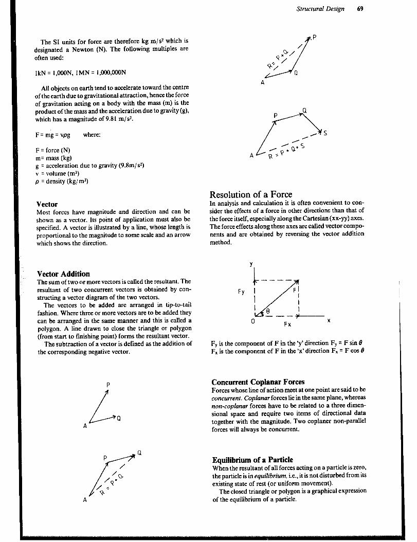
Structural Design 69
The SI units for force are therefore kg m/s2 which is designated a Newton (N). The following multiples are often used:
1kN = l,OOON, IMN = 1,!IOO,OOON
All objects on earth tend to accelerate toward the centre of the earth due to gravitational attraction, hence the force of gravitation acting on a body with the mass (m) is the product of the mass and the acceleration due to gravity(g), which has a magnitude of 9.81 m/s*.
F=mg=vpg where:
F = force (N) m= mass (kg) g = acceleration due to gravity (9.8m/s2) v = volume (m3) p = density (kg/ m3)
Vector Most forces have magnitude and direction and can be shown as a vector. Its point of application must also be specified. A vector is illustrated by a line, whose length is proportional to the magnitude to some scale and an arrow
which shows the direction.
Vector Addition The sum of two or more vectors is called the resultant. The resultant of two concurrent vectors is obtained by con- structing a vector diagram of the two vectors.
The vectors to be added are arranged in tip-to-tail fashion. Where three or more vectors are to be added they can be arranged in the same manner and this is called a polygon. A line drawn to close the triangle or polygon (from start to finishing point) forms the resultant vector.
The subtraction of a vector is defined as the addition of the corresponding negative vector.
P
L P A
Resolution of a Force In analysis and calculation it is often convenient to con- sider the effects of a force in other directions than that of the force itself, especially along the Cartesian (xx-yy) axes. The force effects along these axes are called vector compo- nents and are obtained by reversing the vector addition method.
Y
L ----
FY 1 FI
I
/
I
' 8 --- ?
0 Fx X
FY is the component of F in the ‘y’ direction FY = F sin 6 F, is the component of F in the ‘x’ direction Fx = F cos 8
Concurrent Coplanar Forces Forces whose line of action meet at one point are said to be concurrent. Coplanar forces lie in the same plane, whereas non-coplanar forces have to be related to a three dimen- sional space and require two items of directional data together with the magnitude. Two coplaner non-parallel forces will always be concurrent.
Equilibrium of a Particle When the resultant of all forces acting on a particle is zero, the particle is in equilibrium, i.e., it is not disturbed from its existing state of rest (or uniform movement).
The closed triangle or polygon is a graphical expression of the equilibrium of a particle.

70
The equilibrium of a particle to which a single force is applied may be maintained by the application of second force, which is equal in magnitude and direction, but oppo- site in sense, to the first force. This second force, since it restores equilibrium, is called the equilibriant. When a particle is acted upon by two or more forces, the equilib- riant has to be equal and opposite to the resultant of the system. Thus the equilibriant is the vector drawn closing the vector diagram and connecting the finishing point to the starting point.
P
L Q A
Free-body Diagram of a Particle A sketch showing the physical conditions of a problem is known as a space diagram. This can be reduced to a diagram showing a particle and all the forces acting on it. Such a diagram is called a free-body diagram.
Example 1 Determine the tension in each of the ropes AB and AC
SPACE DIAGRAM
TAB
u
,3 TAC
A
980N
FREE BODY DIAGRAM
for point A
980N
Example 2 A rigid rod is hinged to a vertical support and held at 50° to the horizontal by means of a cable when a weight of 250N is suspended as shown in the figure. Determine the tension in the cable and the compression in the rod, ignoring the weight of the rod.
250N
Space diagram
Free-body diagram for point A
Force Triangle

Structural Design 71
The forces may also be calculated using the law of sines:
Compression in rod =Tension in cable _ 250N
sin 75” sin 40° sin 65”
Point of Concurrency Three coplanar forces that are in equilibrium, must all pass through the same point. This does not necessarily apply for more than three forces.
If two forces (which are not parallel) do not meet at their points of contact with a body such as a structural member, their lines of action can be extended until they meet.
Colinear Forces Colinear forces are parallel and concurrent. The sum of the forces must be zero for the system to be in equilibrium.
Table 4.1 Actions and Reactions
Coplanar, Non-Concurrent, Parallel Forces Three or more parallel forces are required. They will be in equilibrium if the sum of the forces equals zero and the sum of the moments around a point in the plane equals zero. Equilibrium is also indicated by two sums of moments equal to zero.
Reactions Structural components are usually held in equilibrium by being secured to rigid fixing points; these are often other parts of the same structure. The .tixing points or supports will react against the tendency of the app!ied forces (loads) to cause the member to move. So the forces generated in the supports are called reactions.
Flexible cable or rope Force exerted by the cable or rope is always tension away from the fixing, in the direction of the tangent to
the cable curve. -2 ?d
Smooth surfaces Reaction is normal to the surface, i.e., at right angles to
-2_ the tangent.
Rough surface is capable of supporting a tangental force as well as a normal reaction. Resultant reaction is vectorial sum of these two.
Roller support Reaction is normal to the supporting surface only.
Pin support A freely hinged support is fixed in position, hence the two reaction forces, but is not restrained in direction - it is free to rotate.
Built-in support The supi ,rt is capable of providing a longitudinal reaction (H), a lateral or transverse reaction (V), and a moment (M). The body is fixed in position and fixed in
[p ’ 1-1 t-i -LIP direction.
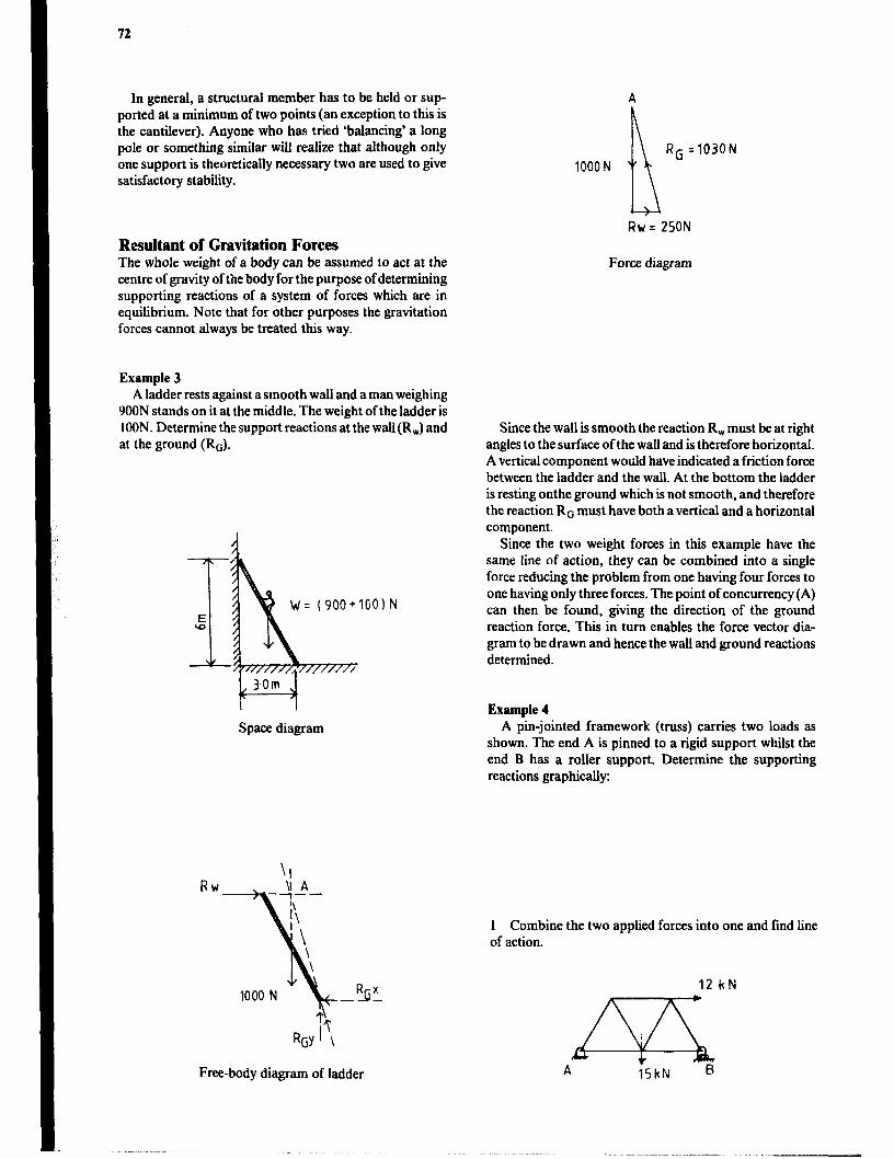
72
In general, a structural member has to be held or sup- ported at a minimum of two points (an exception to this is the cantilever). Anyone who has tried ‘balancing’ a long pole or something similar will realize that although only one support is theoretically necessary two are used to give satisfactory stability.
Resultant of Gravitation Forces The whole weight of a body can be assumed to act at the centre of gravity of the body for the purpose of determining supporting reactions of a system of forces which are in equilibrium. Note that for other purposes the gravitation forces cannot always be treated this way.
Example 3 A ladder rests against a smooth wall and a man weighing
900N stands on it at the middle. The weight of the ladder is IOON. Determine the support reactions at the wall (R,) and at the ground (Ro).
'A'= (900+100) N
3.0m -I Space diagram
r\ RGY I?
Free-body diagram of ladder
A
n
RG =1030N 1000 N
Rw= 250N
Force diagram
Since the wall is smooth the reaction R, must be at right angles to the surface of the wall and is therefore horizontal. A vertical component would have indicated a friction force between the ladder and the wall. At the bottom the ladder is resting onthe ground which is not smooth, and therefore the reaction Ro must have both a vertical and a horizontal component.
Since the two weight forces in this example have the same line of action, they can be combined into a single force reducing the problem from one having four forces to one having only three forces. The point of concurrency (A) can then be found, giving the direction of the ground reaction force. This in turn enables the force vector dia- gram to be drawn and hence the wall and ground reactions determined.
Example 4 A pin-jointed framework (truss) carries two loads as
shown. The end A is pinned to a rigid support whilst the end B has a roller support. Determine the supporting reactions graphically:
1 Combine the two applied forces into one and find line of action.
12 kN
m A 15kN B

Structural Design 73
2 Because of the roller support reaction Ra will be verti- cal. Therefore the resultant line (Rtj must be extended to intersect the vertical reaction of support B. This point is the point of concurrency for the resultant load, the reaction at B and the reaction at A.
3 From this point of concurrency, draw a line through the support pin at A. This gives the line of action of the reaction at A.
4 Use these three force directions and the magnitude of RL to draw the force diagram, from which RA and Ra can be found.
Answer: RA = 12.2 kN at 21’ to horizontal. Ra = 12.7 kN vertical.
The link po!ygon (see an engineering handbook) may also be usea to determine the reactions to a beam or a truss, though it is -usually quicker and easier to obtain the reac- tions by talc ulation, the method shown in Example 4, or a combination of calculation and drawing.
The following conditions must however be satisfied.
1 All forces (apart from the two reactions) must be known completely, i.e., magnitude, line of action and direction. 2 The line of action of one of the reactions must be known. 3 At least one point on the line of action for the other reaction must be known. (2 and 3 reduce the number of unknowns related to the equations of equilibrium to an acceptable level.)
Moments of Forces The effect of a force on a rigid body depends on its point of application as well as its magnitude and direction. It is
common knowledge that a small force can have a large turning effect or leverage. In mechanics, the term moment is used instead of turning effect.
The moment of force with a magnitude (F) about a turning point (0) is defined as: M = F x d, where d is the perpendicular distance from 0 to the line of action of force F. The distance d is often called lever arm. A moment has dimensions of force times length (Nm). The direction of a moment about a point or axis is defined by the direction of the rotation that the force tends to give to the body. A clockwise moment is usually considered as having a posi- tive sign and an anti-clockwise moment a negative sign.
The determination of the moment of a force in a coplanar system will be simplified if the force and its point of application are resolved into its horizontal and vertical components.
Free-body Diagram for a Rigid Body In solving a problem it is essential to consider all forces acting on the body and to exclude any force which is not directly applied to the body. The first step in the solution of a problem should therefore be to draw a free-body diagram.
1 Choose the free body to be used, isolate it from any other body and sketch its outline. 2 Locate all external forces on the free body and clearly mark their magnitude and direction. This should include the weight of the free body which is applied at the centre of gravity. .
3 Locate and mark unknown external forces and reac- tions, in the free-body diagram. 4 Include all dimensions that indicate the location, and direction of forces.
Example 3 continued Since the ladder in Example 3 is at rest, the conditions of
equilibrium for a rigid body can be used to calculate the reactions. By taking moments around the point where the ladder rests on the ground, the moment of the reaction Ro can be ignored since it has no lever arm (moment is zero). According to the third condition for equilibrium, the sum of moments must equal zero, therefore:
(6 x R,) - (900N x 1.5m) - (1OON x 1.5m) = 0 R, = 250N
The vertical component of Ro must, according to the second condition, be equal but opposite to the sum of the weight of the ladder and the weight of the person on the ladder, since those two are the only vertical forces and the sum of the vertical forces must equal zero.
i.e... Roy q RIOON

74
Using the first condition of equilibrium it can be seen that the horizontal component of Ro must be equal but opposite in direction to R, i.e.;
Ron = 250N
Since Ro is the third side of a force triangle, where the other two sides are the horizontal and vertical components, the magnitude of R. can be calculated as:
lOOO* + 2502 = 1030N
Resultant of Parallel Forces If two or more parallel forces are applied to a horizontal beam, then theoretically the beam can be held in equili- brium by the application of a single force (reaction) which is equal and opposite to the resultant, R. The equilibrant of the downward forces must be equal and opposite to their resultant. This provides a method for calculating the resul- tant of a system of parallel forces. However, two reactions are required to ensure the necessary stability and a more likely arrangement will have two or more supports.
The reactions RA and Ra must both be vertical, since there is no horizontal force component. Furthermore the sum of the reaction forces RA and Ra must be equal to the sum of the downward acting forces.
Beam Reactions
BOkN 70kN 100kN 30kN
The magnitude of the reactions may be found by the application of the third condition for equilibrium, i.e., the algebraic sum of the moments of the forces about any point must be zero.
Take the moments around point A, then:
(80 x 2) + (70 x 4) + (100 x 7) + (30 x 10) - (Ra x 12) = 0; Ra = 120kN
RA is now easily found with the application of the second condition for equilibrium.
RA-75-70- RIO-30+Ra=O; Ra = 120kN gives: RA = 160kN.
Couples Two equal, parallel and opposite but not colinear forces are said to be a couple.
A couple acting on a body produces rotation. Note that the couple cannot be balanced by a single force. To pro- duce equilibrium another couple of equal and opposite moment is required.
150mm k __.- - i
150mm
I+---- ---_-.--- --1 F = 20N
F= 20N
Loading Systems Before any of the various load effects (tension, compres- sion, bending etc.) can be considered, the applied loads must be rationalized into a number of ordered systems. Irregular loading is difficult to deal with exactly but even the most irregular loads may be reduced and approximated to a number of regular systems. These can then be dealt with in mathematical terms using the principle of superpo- sition to estimate the overall combined effect.
Concentrated loads are those which can be assumed to act at a single point e.g., a weight hanging from a ceiling, or a man pushing against a box.
Concentrated loads are represented by a single arrow drawn in the direction and through the point of action of the force. The magnitude of the force is always indicated.
Uniformly distributed loach written as u.d.1. are those which can be assumed to act uniformly over an area or along the length of a structural member, e.g., roof loads, wind loads, the effect of the weight of water on a horizontal surface, etc. 2
For the purpose of calculation, a u.d.1. is normally con- sidered in a plane and is represented as shown.
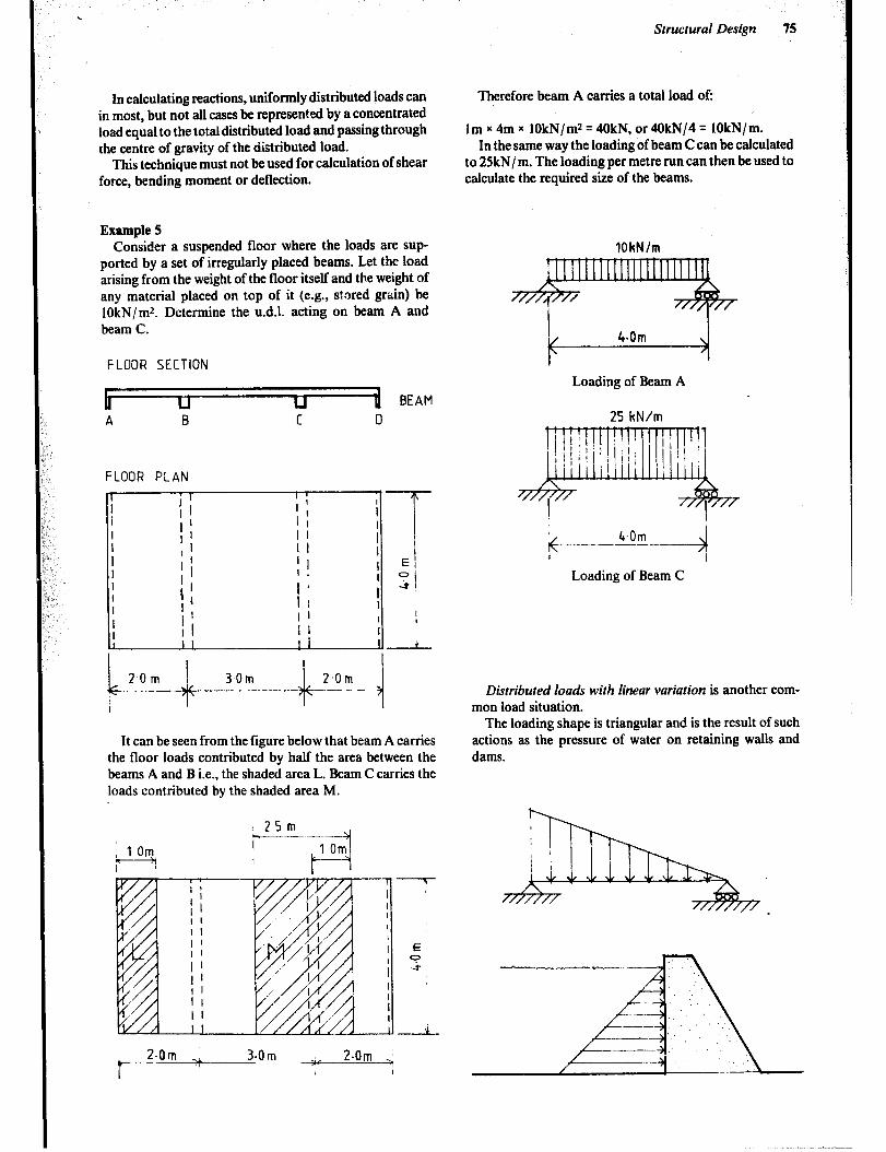
.
In calculating reactions, uniformly distributed loads can in most, but not all cases be represented by a concentrated load equal to the total distributed load and passing through the centre of gravity of the distributed load.
This technique must not be used for calculation of shear force, bending moment or deflection.
Example 5 Consider a suspended floor where the loads are sup-
ported by a set of irregularly placed beams. Let the load arising from the weight of the floor itself and the weight of any material placed on top of it (e.g., stored grain) be lOkN/mZ. Determine the u.d.1. acting on beam A and beam C.
FLOOR SECTION
2 BEAM A B C 0
FLOOR PLAN
It can be seen from the figure below that beam A carries the floor loads contributed by half the area between the beams A and B i.e., the shaded area L. Beam C carries the loads contributed by the shaded area M.
2.0rn i
f- ‘I
3.0m _<, 2.0mi I
Structural Design 15
Therefore beam A carries a total load of:
lm x 4m x lOkN/m* = 4OkN, or 4OkN/4 = lOkN/m. In the same way the loading of beam C can be calculated
to 25kN/ m. The loading per metre run can then be used to calculate the required size of the beams.
lOkN/m
Loading of Beam A
25 kN/m
Ic 6.Om _ .--.-_-_-
Loading of Beam C
Distributed loads with linear variation is another com- mon load situation.
The loading shape is triangular and is the result of such actions as the pressure of water on retaining walls and dams.
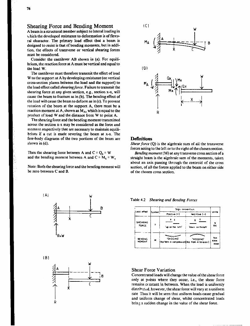
76
Shearing Force and Bending Moment A beam is a structural member subject to lateral loading in which the developed resistance to deformation is of flexu- ml character. The primary load effect that a beam is designed to resist is that of bending moments, but in addi- tion, the effects of transverse or vertical shearing forces must be considered.
Consider the cantilever AB shown in (a). For equili- brium, the reaction force at A must be vertical and equal to the load W.
The cantilever must therefore transmit the effect of load W to the support at A by developing resistance (on vertical cross-section planes between the load and the support) to the load effect called shearingforce. Failure to transmit the shearing force at any given section, e.g., section x-x, will cause the beam to fracture as in (b). The bending effect of the load will cause the beam to deform as in(c). To prevent rotation of the beam at the support A, there must be a reaction moment at A, shown as MA, which is equal to the product of load W and the distance from W to point A.
The shearing force and the bending moment transmitted across the section x-x may be considered as the force and moment respectively that are necessary to maintain equili- brium if a cut is made severing the beam at x-x. The free-body diagrams of the two portions of the beam are shown in (d).
Then the shearing force between A and C = Q, q W and the bending moment between A and C = M, = W,
Note: Both the shearing force and the bending moment will be zero between C and B.
(0)
Defmitions Shear force (Q) is the algebraic sum of ail the transverse forces acting to the left or to the right of the chosen section.
Bending moment (M) at any transverse cross section of a straight beam is the algebraic sum of the moments, taken about an axis passing through the centroid of the cross section, of all the forces applied to the beam on either side of the chosen cross section.
Table 4.2 Shearing and Bending Forces
(B)
Shear Force Variation Concentrated loads will change the value of the shear force only at points where they occur, i.e., the shear force remains constant in between. When the load is uniformly distributed, however, the shear force will vary at a uniform rate Thus it will be seen that uniform loads cause gradual and uniform change of shear, whilst concentrated loads briq; a sudden change in the value of the shear force.

Structural Design 77
Bending Moment Variation Concentrated loads will cause a uniform change of the bending moment between the points of action of the loads. In the case of uniformly distributed loads, the rate of change of the bending moment will be parabolic. Maxi- mum values of bending moment will occur where the shear force is zero or where it changes sign.
Shear-Force and Bending-Moment Diagrams Representative diagrams of the distribution of shearing force and bending moment are often required at several stages in the design process. These diagrams are obtained by plotting graphs with the beams as the base and the values of the particular effect as ordinates. It is usual to construct these diagrams in sds of three, representing the distribution of loads, shearing forces and bending moments respectively. These graphical representations provide useful information regarding:
a the most likely section where a beam may fail in shear or in bending b where reinforcement may be required in certain types of beams, e.g., concrete beams c the shear-force diagram will provide usefttl information about the bending moment at any point d the bending-moment diagram gives useful information on the deflected shape of the beam.
The following example will show how the three dia- grams are constructed:
Example 6 1 Draw a beam-loading diagram showing all loads and relevant dimensions. This is simply a free-body diagram of the beam.
2 Determine the reactions at the supports. First use the condition for equilibrium of moments about point E. 1Mr q 0.
;E l ;o;; 10) + (2 x 10 x 5) + 4 x 10 x (15) - Ro (20) = 0
G
IF, = 0 hence ZF,,=Rz+Ro-P-(w,xb)-(w+)=O lFY = RE + 30 - 10 - (2 x 10) - (4 x 10) = 0 RE q 40kN
3 Draw the shear-force diagram(SFD) directly below the loading diagram and choose a convenient scale to represent the shear force.
Calculate the values of the shear force to the left and to the right of all critical points. Critical points are:
0 at concentrated loads l at reactions 0 at points where the magnitude of a distributed load changes.
a Consider a section through the beam just to the left of D, and find the algebraic sum of all vertical forces to the left of this section. IF, = 0 :. shear force to the left of D is zero b Consider a section just to the right of D, algebraic sum of forces to left of this section is 1OkN down to the left.
Hence shear force to right of D is 1OkN (Negative) c The same resul 1s in 2) above will be found for any such section between D and E. The shear-force diagram between D and E is thus a horizontal line at -1OkN. d Consider a section just to the right of E, algebraic sum of forces to the left of this section is made up of P and Rz given, shear force equals (-10 + 40)kN = + 3OkN, i.e., up to the left of section. Thus at E shear-force diagram changes from -1OkN to + 30kN.
As we approach the right-hand end of the beam we find the mathematics easier to consider the right hand side of any section. e Section just to left of F, shear force = (4kN/ m x 1Om) - (30kN) using the sign convention to determine positive or negative. Shear force here equals + 40 - 30 = + 1OkN. f Section just to right of F, shear force = + 40 - 30 = +lOkN (i.e., no sudden change at F). g Section just to left of G, shear force = -3OkN h Variation of shear under a u.d.1. must be linear.
0: 10m b= 10m c:lOm c *- *- -..
-I
IR+OkN 1 Pp 30kN
kN I
30.
20.
10.
SF0
-301
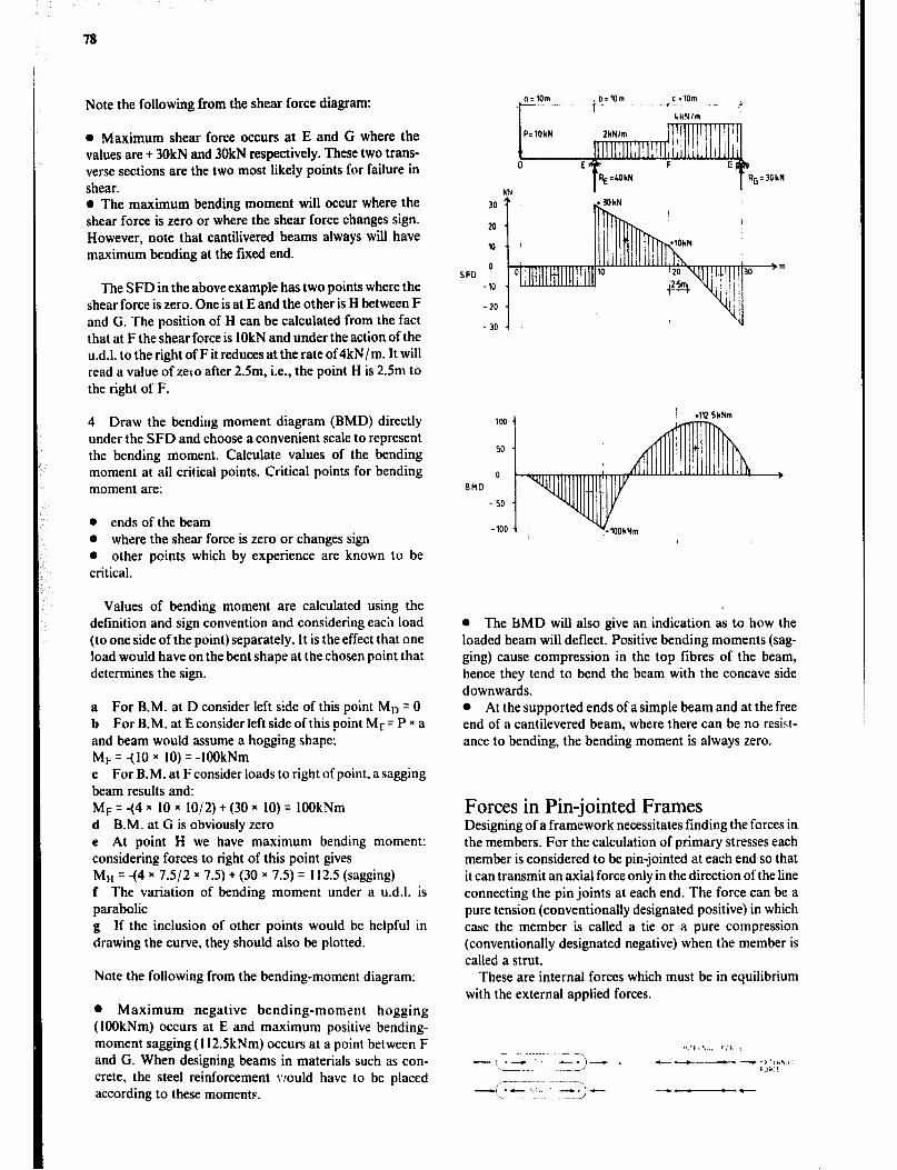
78
Note the following from the shear force diagram:
l Maximum shear force occurs at E and G where the values are + 30kN and 30kN respectively. These two trans- verse sections are the two most likely points for failure in shear. l The maximum bending moment will occur where the shear force is zero or where the shear force changes sign. However, note that cantilivered beams always will have maximum bending at the fixed end.
The SFD in the above example has two points where the shear force is zero. One is at E and the other is H between F and G. The position of H can be calculated from the fact that at F the shear force is 1OkN and under the action of the u.d.1. to the right of F it reduces at the rate of 4kN/ m. It will read a value of zero after 2Sm, i.e., the point H is 2.5m to the right of F.
4 Draw the bending moment diagram (BMD) directly under the SFD and choose a convenient scale to represent the bending moment. Calculate values of the bending moment at all critical points. Critical points for bending moment are:
l ends of the beam l where the shear force is zero or changes sign l other points which by experience are known to be critical.
Values of bending moment are calculated using the definition and sign convention and considering each load (to one side of the point) separately. It is the effect that one load would have on the bent shape at the chosen point that determines the sign.
a For B.M. at D consider left side of this point Mt, = 0 b For B.M. at E consider left side of this point ME= P x a and beam would assume a hogging shape; MF = -(lo x 10) q -1OOkNm c For B.M. at F consider loads to right of point, a sagging beam results and: MF = -(4 x 10 x 1012) + (30 x 10) q IOOkNm d B.M. at G is obviously zero e At point H we have maximum bending moment: considering forces to right of this point gives MH q -(4 x 7.5/2 x 7.5) + (30 x 7.5) q 112.5 (sagging) f The variation of bending moment under a u.d.1. is parabolic g If the inclusion of other points would be helpful in drawing the curve, they should also be plotted.
Note the following from the bending-moment diagram:
l Maximum negative bending-moment hogging (IOOkNm) occurs at E and maximum positive bending- moment sagging (112.5kNm) occurs at a point between F and G. When designing beams in materials such as con- crete, the steel reinforcement vjould have to be placed according to these moments.
o:lOm
I-- -
kN
I
103
50 I' AfllllT /
+112 5kNm
0
en0
- 50
-100
0 The BMD will also give an indication as to how the loaded beam will deflect. Positive bending moments (sag- ging) cause compression in the top fibres of the beam, hence they tend to bend the beam with the concave side downwards. l At the supported ends of a simple beam and at the free end of a cantilevered beam, where there can be no resist- ance to bending, the bending moment is always zero.
Forces in Pin-jointed Frames Designing of a framework necessitates finding the forces in the members. For the calculation of primary stresses each member is considered to be pin-jointed at each end so that it can transmit an axial force only in the direction of the line connecting the pin joints at each end. The force can be a pure tension (conventionally designated positive) in which case the member is called a tie or a pure compression (conventionally designated negative) when the member is called a strut.
These are internal forces which must be in equilibrium with the external applied forces.
-i .C t.,. *_
--I)- --t

To determine the forces in the members one can use a number of different techniques.
Joint analysis: This is based on considering the equili- brium of each joint in turn and using the free-body diagram for each joint.
Method of sections: The free-body diagram consi- dered is for a portion of the framework to one side or the other of a cut section. The forces in the members cut by the section are included in the free-body diagram. Application of the equations of equilibritrm will solve the unknown forces in the cut section. This provides an analytical solu- tion and is most useful when requiring the answers for one or two members only.
Example 7
9 kN 12 kN 9kN
, 10m , 10m , l0m , 10m , 1 I I
( all 3@~60°,900tr~an~le I I
Find the forces and theirdirection in the members BH and HG by using the method of sections.
Fuo is found by taking a moment about point C, consider- ing the right hand section (RHS) of the cut 1-I is in equilibrium. The forces Fuc and Fat have no moment about point CaL since they intersect at and pass through the point.
tM, = 0 :‘(Fno x CG) + (9 x CD) - (Rs x 20) = 0 CG = FX = 10 tan 30” = 5,774
CD=DE=FE cos 300
FE=s0 = 11.547m
Structural Design 79
CD= 11,547 - = 13,333m cos3OO
RE= w. 15kN
Hence (Fuo x 5,774) + (9 x 13,333) - (15 x 20) = 0 Fno = 31,17
E
Take section 2-2.
Since HC = FE = 11,547 (Faux 11,547)+(9 x 13,333)-(15x 20)=0 FaN = 15,59kN
It can be seen that Fou and Fau and Fau must be clockwise to have equilibrium about point C. The members GH and HB are therefore in tension.
Mechanics of Materials
Direct Stress When a force is transmitted through a body, the body tends to change its shape. Although these deformations seldom can be seen by the naked eye, the many tibres or particles which make up the body, transmit the force throughout the length and section of the body, and the iibres doing this work are said to be in a state of stress. Thus, a stress may be described as a mobilized internal reaction which resists any tendency towards deformation. Since the effect of the force is distributed over the cross-section area of the body, stress is defined as force transmitted or resisted per unit area.
Thus Stress = E
The unit for stress in S.I. is newtons per square metre (N/ml). This is also called a Pascal (Pa). However, it is often more convenient to uses ihe multiple N/ mm2.
Note that lN/mmZ= I MN/mJ= IMPa
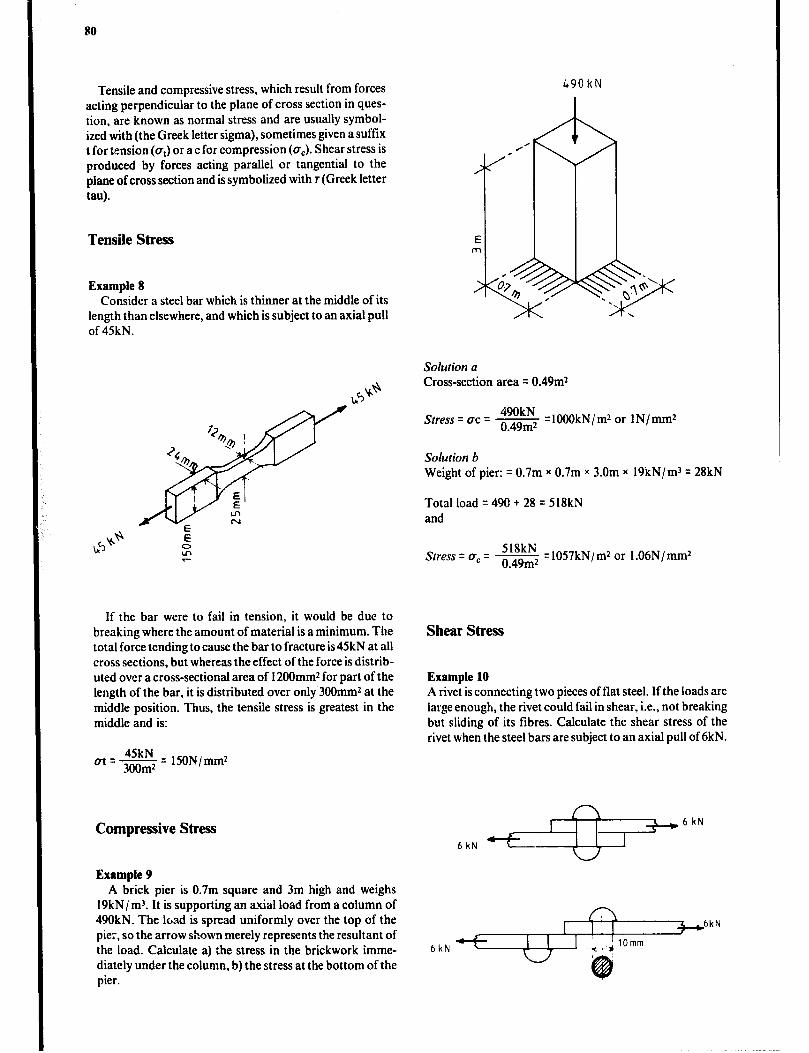
80
Tensile and compressive stress, which result from forces acting perpendicular to the plane of cross section in ques- tion, are known as normal stress and are usually symbol- ized with (the Greek letter sigma), sometimes given a suffix t for tension (a,) or a c for compression (a,). Shear stress is produced by forces acting parallel or tangential to the plane of cross section and is symbolized with T (Greek letter tau).
Tensile Stress
Example 8 Consider a steel bar which is thinner at the middle of its
length than elsewhere, and which is subject to an axial pull of 45kN.
Gi
if the bar were to fail in tension, it would be due to breaking where the amount of material is a minimum. The total force tending to cause the bar to fracture is 45kN at all cross sections, but whereas the effect of the force is distrib- uted over a cross-sectional area of 12OOmmz for part of the length of the bar, it is distributed over only 3OOmm2 at the middle position. Thus, the tensile stress is greatest in the middle and is:
m - 45kN - 300m2 - EON/mm2
Compressive Stress
Example 9 A brick pier is 0.7m square and 3m high and weighs
19kN/ m3. It is supporting an r&al load from a column of 490kN. The load is spread uniformly over the top of the pie;, so the arrow shown merely represents the resultant of the load. Calculate a) :he stress in the brickwork imme- diately under the column, b) the stress at the bottom of the pier.
490kN
Solution a Cross-section area = 0.49m2
Stress = uc = 490kN
- =lOOOkN/m2 or IN/mm2 o 49m2
Solution b Weight of pier: = 0.7m x 0.7m x 3.0m x 19kN/m3 = 28kN
Total load = 490 + 28 = 518kN and
Stress = UC = 518kN
- =1057kN/m2 or l.06N/mm2 o 49m2
Shear Stress
Example 10 A rivet is connecting two pieces of flat steel. If the loads are large enough, the rivet could fail in shear, i.e., not breaking but sliding of its fibres. Calculate the shear stress of the rivet when the steel bars are subject to an axial pull of 6kN.
6kN
6kN -
+6kN
I 6kN
I 1
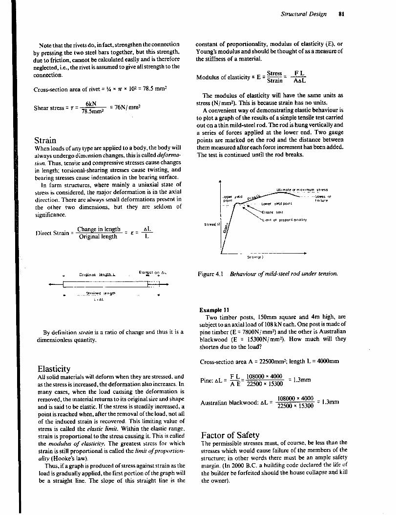
Structural Design 81
Note that the rivets do, in fact, strengthen the connection by pressing the two steel bars together, but this strength, due to friction, cannot be calculated easily and is therefore neglected, i.e., the rivet is assumed to give all strength to the connection.
Cross-section area of rivet = r/4 x a x 102 = 78.5 mm2
Shear stress = T = 71:im2 = 76N/mmz
Strain When loads of any type are applied to a body, the body will always undergo dimension changes, this is called deforma- tion. Thus, tensile and compressive stresses cause changes in length; torsional-shearing stresses cause twisting, and bearing stresses cause indentation in the bearing surface.
In farm structures, where mainly a uniaxial state of stress is considered, the major deformation is in the axial direction. There are always small deformations present in the other two dimensions, but they are seldom of significance.
Direct Strain = Change in length AL
Original length = ’ = r
By definition srrain is a ratio of change and thus it is a dimensionless quantity.
Elasticity All solid materials will deform when they are stressed, and as the stress is increased, the deformation also increases. In many cases, when the load causing the deformation is removed, the material returns to its original size and shape and is said to be elastic. if the stress is steadily increased. a point is reached when, after the removal of the load, not all of the induced strain is recovered. This limiting value of stress is called the elastic limit. Within the elastic range, strain is proportional to the stress causing it. This is called the modulus of elasticity. The greatest stress for which strain is still proportional is called the limit ofproportion- ality (Hooke’s law).
Thus, if agraph is produced of stress against strain as the load is gradually applied, the first portion of the graph will be a straight line. The slope of this straight line is the
constant of proportionality, modulus of elasticity (E), or Young’s modulus and should be thought of as a measure of the stiffness of a material.
Stress F L Modulus of elasticity = E = ~tr~-n = -
AAL
The modulus of elasticity will have the same units as stress (N/ mmz). This is because strain has no units.
A convenient way of demonstrating elastic behaviour is to plot a graph of the results of a simple tensile test carried out on a thin mild-steel rod. The rod is hung vertically and a series of forces applied at the lower end. Two gauge points are marked on the rod and the distance between them measured after each force increment has been added. The test is continued until the rod breaks.
Figure 4.1 Behaviour of mild-steel rod under tension.
Example 11 Two timber posts, 150mm square and 4m high, are
subject to an axial load of 108 kN each. One post is made of pine timber (E = 7800N / mmz) and the other is Australian blackwood (E = 153OON/mm*). How much will they shorten due to the load?
Cross-section area A = 225OOmmz; length L = 4OOOmm
Pine: AL q rE= 22500 x 15300 FL 108000~4000 =13mm
.
Australian blackwood: AL q 22500 x ,5300 108000r4OOO =, 3mm
.
Factor of Safety The permissible stresses must, of course, be less than the stresses which would cause failure of the members of the structure; in other words there must be an ample safety margin. (In 2000 B.C. a buildiing code declared the life of the builder be forfeited should the house collapse and kill the owner).
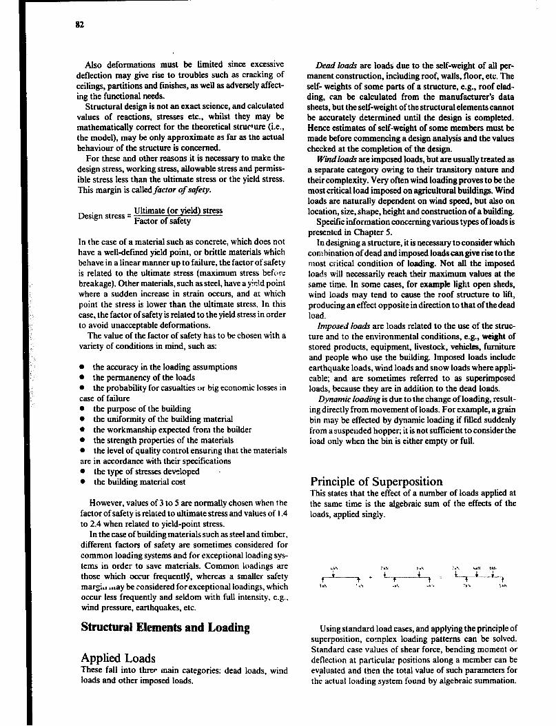
82
Also deformations must be limited since excessive deflection may give rise to troubles such as cracking of ceilings, partitions and finishes, as well as adversely affect- ing the functional needs.
Structural design is not an exact science, and calculated values of reactions, stresses etc., whilst they may be mathematically correct for the theoretical strur*ure (i.e., the model), may be only approximate as far as the actual behaviour of the structure is concerned.
For these and other reasons it is necessary to make the design stress, working stress, allowable stress and permiss- ible stress less than the ultimate stress or the yield stress. This margin is calledfictor of safety.
Design stress = Ultimate (or yield) stress Factor of safety
In the case of a material such as concrete, which does not have a welldefined yield point, or brittle materials which behave in a linear manner up to failure, the factor of safety is related to the ultimate stress (maximum stress befc1l.e breakage). Other materials, such as steel, have a yield point where a sudden increase in strain occurs, and at which point the stress is lower than the ultimate stress. In this case, the factor of safety is related to the yield stress in order to avoid unacceptable deformations.
The value of the factor of safety has to be chosen with a variety of conditions in mind, such as:
l the accuracy in the loading assumptions l the permanency of the loads l the probability for casualties or big economic losses in case of faihtre l the purpose of the building l the uniformity of the building material 0 the workmanship expected from the builder l the strength properties of the materials l the level of quality control ensuring that the materials are in accordance with their specifications 0 the type of stresses developed - 0 the building material cost
However, values of 3 to 5 are normally chosen when the factor of safety is related to ultimate stress and values of 1.4 to 2.4 when related to yield-point stress.
In the case of building materials such as steel and timber. different factors of safety are sometimes considered for common loading systems and for exceptional loading sys- tems in order to save materials. Common loadings are those which occur frequently, whereas a smaller safety margL ticay be :onsidered for exceptional loadings, which occur less frequently and seldom with full intensity, e.g., wind pressure, earthquakes, etc.
Structural Elements and Loading
Applied Loads These fall into threP main categories: dead loads, wind loads and other imposed loads.
Dead loads are loads’ due to the self-weight of all per- manent construction, including roof, walls, floor, etc. The self- weights of some parts of a structure, e.g., roof clad- ding, can be calculated from the manufacturer’s data sheets, but the self-weight of the structural elements cannot be accurately determined until the design is completed. Hence estimates of self-weight of some members must be made before commencing a design analysis and the values checked at the completion of the design.
Windloads are imposed loads, but are usually treated as a separate category owing to their transitory nature and their complexity. Very often wind loading proves to be the most critical load imposed on agricultural buildings. Wind loads are naturally dependent on wind speed, but also on location, size, shape, height and construction of a building.
Specific information concerning various types of loads is presented in Chapter 5.
In designing a structure, it is necessary to consider which corn hination of dead and imposed loads can give rise to the most critical condition of loading. Not all the imposed loads will necessarily reach their maximum values at the same time. In some cases, for example light open sheds, wind loads may tend to cause the roof structure to lift, producing an effect opposite in direction to that of the dead load.
Imposed loa& are loads related to the use of the stntc- ture and to the environmental conditions, e.g., weight of stored products, equipment, livestock, vehicles, furniture and people who use the building. Imposed loads include earthquake loads, wind loads and snow loads where appli- cable; and are sometimes referred to as superimposed loads, because they are in addition to the dead loads.
Dynamic loading is due to the change of loading, result- ing directly from movement of loads. For example, a grain bin may be effected by dynamic loading if filled suddenly from a suspeuded hopper; it is not sufficient to consider the load only when the bin is either empty or full.
Principle of Superposition This states that the effect of a number of loads applied at the same time is the algebraic sum of the effects of the loads, applied singly.
Using standard load cases, and applying the principle of superposition, complex loading patterns can be solved. Standard case values of shear force, bending moment or deflection at particular positions along a member can be evaluated and then the total value of such parameters for the actual loading system found by algebraic summation.
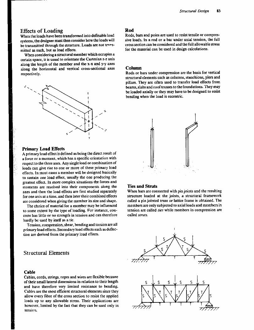
Structural Design 83
Effects of Loading When the loads have been transformed into definable load systems, the designer must then consider how the loads will be transmitted through the structure. Loads are not trl)*s- mitted as such, but as load effects.
When considering a structural member which occupies a certain space, it is usual to orientate the Cartesian z-z axis along the length of the member and the x-x and y-y axes along the horizontal and vertical cross-sectional axes respectively.
+ /
Primary Load Effects A primary load effect is defined as being the direct result of a force or a moment, which has a specific orientation with respect to the three axes. Any single load or combination of loads can give rise to one or more of these primary load effects. In most cases a member will be designed basically to sustain one load effect, usually the one producing the greatest effect. In more complex situations the forces and moments are resolved into their components along the axes and then the load effects are first studied separately for one axis at a time, and then later their combined effects are considered when giving the member its size and shape.
The choice of material for a member may be influenced to some extent by the type of loading. For instance, con- crete has little or no strength in tension and can therefore hardly be used by itself as a tie.
Tension, compression, shear, bending and torsion are all primary load effects. Secondary load effects such as deflec- tion are derived from the primary load effects.
Structural Elements
Cable Cables, cords, strings, ropes and wires are flexible because of their small lateral dimensions in relation to their length and have therefore very limited resistance to bending. Cables are the most ef!icient structural elements since they allow every libre of the cross section to resist the applied loads up to any allowable stress. Their applications are however, limited by the fact that they can be used only in tension.
Rod Rods, bars and poles are used to resist tensile or compres- sive loads. In a rod or a bar under axial tension, the full cross section can be considered and the full allowable stress for the material can be used in design calculations.
Column Rods or bars under compression are the basis for vertical structural elements such as columns, stanchions, piers and pillars. They are often used to transfer load effects from beams, slabs and roof trusses to the foundations. They may be loaded axially or they may have to be designed to resist bending when the load is eccentric.
.:I, .i^ . . . . ‘. : . . Ties and Struts When bars are connected with pin joints and the resulting structure loaded at the joints, a structural framework called a pin jointed truss or lattice frame is obtained. The members are only subjected to axial loads and members in tension are called ties while members in compression are called struts.
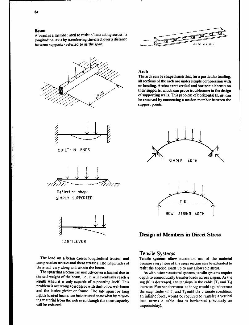
Beam A beam is a member used to resist a load acting across its longitudinal axis by transferring the effect over a distance between supports - referred to HS the span.
BUILT - IN ENDS
Deflection shape
SIMPLY SUPPORTED
CANTILEVER
The load on a beam causes longitudinal tension and compression stresses and shear stresses. The magnitudes of these will vary along and within the beam.
The span that a beam can usefully cover is limited due to the self-weight of the beam, i.e , it will eventually reach a length when it is only capable of supporting itself. This problem is overcome to a degree with the hollow web beam and the lattice girder or frame. The safe span for long lightly loaded beams can be increased somewhat by remov- ing material from the web even though the shear capacity will be reduced.
Arch The arch can be shaped such that, for a particular loading, all sections of the arch are under simple compression with no bending. Arches exert vertical and horizontal thrusts on their supports, which can prove troublesome in the design of supporting walls. This problem of horizontal thrust can be removed by connecting a tension member between the support points.
I BOW STRING ARCH I
Design of Members in Direct Stress
Tensile Systems Tensile systems allow maximum use of the material because every tibre of the cross section can be extended to resist the applied loads up to any allowable stress.
As with other structural systems, tensile systems require depth to economically transfer loads across a span. As the sag (h) is decreased, the tensions in the cable (Tt and Tz) increase. Further decreases in the sag would again increase the magnitudes of Tt and T2 until the ultimate condition, an infinite force, would be required to transfer a vertical load across a cable that is horizontal (obviously an impossibility).

Structural Design 85
I 'P
If P= 100N T, = T7= 58
72 Tl 4 P
FORCE DIAGRAM FOR POINT A
If P=lOON
then
Tl = T2 q lOON
I WP
FORCE DIAGRAM FOR POINT A
A distinguishing feature of tensile systems is that vertical loads produce both vertical and horizontal reactions. Because cables cannot resist bending or shear, they transfer all loads in tension along their lengths. The connection of a cable to its supports acts as a pin joint (hinge) with the result that the reaction (R) must be exactly equal and opposite to the tension in the cable (T). The R can be resolved into the vertical and horizontal directions produc- ing the forces V and H. The horizontal reaction (H) is known as the thrust.
The values of the components of the reactions can be obtained by using the conditions of static equilibrium and resolving the cable tensions into vertical and horizontal components at the support points.
Example 12 Two identical ropes support a load R of 5 kN as shown in
the figure. Calculate the required diameter of the rope, ifits ultimate strength is 30 N/mm* and a factor of safety of 4.0 is applied. Also determine the horizontal support reaction at B.
Tl ”
T2
p’
FREE BODY DIAGRAM

5kN
The allowable stress in the rope is F = 7.5N/mmz
Stress Fora
= urea area required
thus d =
BH
At support B, reaction composed of two components.
Bv = T2 sin 30” = 2.5 sin 30’ = 1.25kN Bn q Tz cos 30’ = 2.5 cos 30” = 2.17kN
Short Columns A column which is short (i.e., the height is small compared to the cross section area) is likely to fail due to crushing of the material.
Note however, that slender columns, being tall com- pared to the cross section area, are more likely to fail by buckling with a much smaller load than that which would cause failure due to CNShhg. Buckling is dealt with later.
Short columns
b I
Slender columns
Example 13 A square concrete column, which is 0.5m high, is made
of a nominal concrete mix of 1:2:4, with a permissible direct compression stress of 5.3N/mmr. What is the required cross section area if the column is required to carry an axial load of 3OOkN?
A= $= 3OOOOON 5.3N/mm2
= 566OOmm2
i.e., the column should be minimum 240mm square.
Properties of Structural Sections It will be necessary, for example, when designing beams in bending, columns in buckling, etc., to refer to a number of basic georrctrical properties of the cross sections of struc- tural members.
Area Cross-section areas (A) are generally calculated in mm2, since the dimensions of most struCtural members are given in mm, and values for design stresses found in tables are usually given in N/ mm2.

Centre of Gravity or Centroid This is a point about which the area of the section is evenly distributed. Note that the centroid is sometimes outside the actual cross section of the structural element.
Reference Axes It is usual to consider the reference axes of structural sections as those passing through the centraid. In general, the x-x axis is drawn perpendicular to the greatest lateral dimension of the section, and the y-y axis is drawn perpen- dicular to the x-x axis, intersecting it at the centroid.
Swuctural Design 87
Moment of Inertia Area moment of inertia (I), or as it is correctly called, second moment of area, is a property which measures the distribution of area around a particular axis of a cross section, and is an important factor in its resistance to bending. Other factors such as the strength of the material from which a beam is made, are also important for resist- ance to bending, and are allowed for in other ways. The moment of inertia only measures how the geometric prop- erties or shape of a section affects its value as a beam or slender column. The best shape for a section is one which has the greater part of its area as far as possible away from its centroidal, neutral axis.
For design purposes it is necessary to use the moment of inertia of a section about the relevant axis or axes.
Calculation of Moment of Inertia Consider a rectangle and let it consist of an infinite number of strips. The moment of inertia about the x-x axis of such a strip is then the area of the strip multiplied by the square of the perpendicular distance from its centroid to the x-x axis, i.e.: b x Ay x y*.
Y
Y X
x- - C
I
X
I Y
Y
x
b
ic e X
Y
-~
d/2
The sum of all such products is the moment of inertia about the x-x axis for the whole cross section.
By applying calculus and integrating as follows, the exact value for the moment of inertia can be obtained.
+d/2
1,x = /
bd3 by2 dy =w
d/2
For a circular cross section:
1 WD4
xx = 64
Moments of inertia for other cross sections are given later and in Table 4.3. For str’uctural rolled-steel sections, the moment of inertia can be found tabu!ated in hand- books. Some examples are given in Appendix V:J.
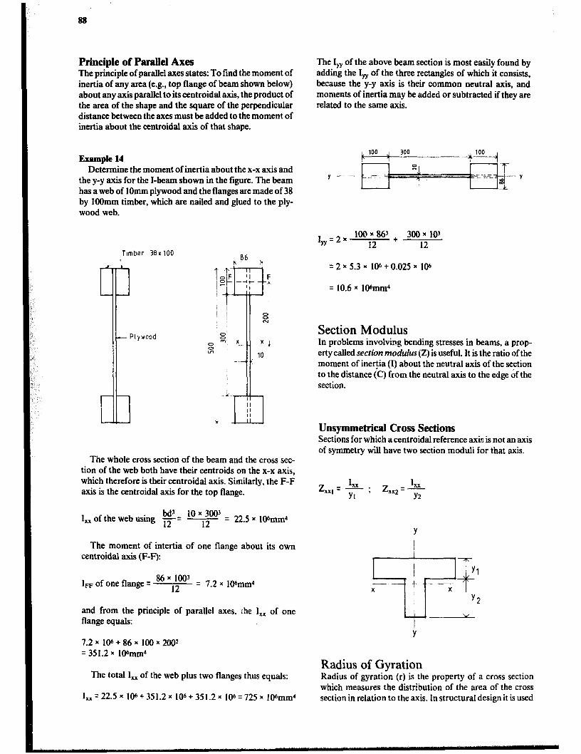
88
Principle of Parallel Axes The principle of parallel axes states: To find the moment of inertia of any area (e.g., top flange of beam shown below) about any axis parallel to its centroidal axis, the product of the area of the shape and the square of the perpendicular distance between the axes must be added to the moment of inertia about the centroidal axis of that shape.
Example 14 Determine the moment of inertia about the x-x axis and
the y-y axis for the I-beam shown in the figure. The beam has a web of 1Omm plywood and the flanges are made of 38 by 1OOmm timber, which are nailed and glued to the ply- wood web.
Timber 39x100
- Plywood
1 The whole cross section of the beam and the cross sec-
tion of the web both have their centroids on the x-x axis, which therefore is their centroidal axis. Similarly, the F-F axis is the centroidal axis for the top flange.
bd3 10x 3003 I, of the web using r= 12 = 22.5 x 10Smm4
The moment of intertia of one flange about its own centroidal axis (F-F):
1~ of one flange = 86 x 1003
l2 q 7.2 x 106mm4
and from the principle of parallel axes, :he I,, of one flange equals:
7.2~ 106+86x IOOx2OOr = 351.2 x IWmm’
The total I,, of the web plus two flanges thus equals:
1,,=22.Sx 106+351.2x 10⁶+351.2x 106=725x 106mm4
The I, of the above beam section is most easily found by adding the I, of the three rectangles of which it consists, because the y-y axis is their common neutral axis, and moments of inertia may be added or subtracted if they are related to the same axis.
1,=2x loo x 863 x
12 + 300 103
12
q 2 x 5.3 x 106 + 0.025 x 106
= 10.6 x IO%nnr’
Section Modulus In problems involving bending stresses in beams, a prop- erty called secrion modulus(Z) is useful. It is the ratio of the moment of inertia (I) about the neutral axis of the section to the distance (C) from the neutral axis to the edge if the section.
Unsymmetrical Cross Sections Sections for which acentroidal reference axis is not an axis of symmetry will have two section moduli for that axis.
Y
: Y1 - X
T- t ---y T
I y2
--.-..A
Y
Radius of Gyration Kadius of gyration (r) is the property of a cross section which measures the distribution of the area of the cross section in relation to the axis. In structural design it is used
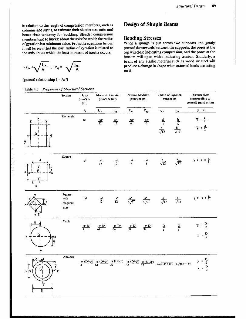
Structural Design 89
in relation to the length of compression members, such as columns and struts, to estimate their slenderness ratio and hence their tendency for buckling. Slender compression members tend to buckle about the axis for which the radius of gyration is a minimum value. From the equations below, it will be seen that the least radius of gyration is related to the axis about which the least moment of inertia occurs.
Design of Simple Beams
Bending Stresses When a sponge is put across two supports and gently pressed downwards between the supports, the pores at the top will close indicating compression, and the pores at the bottom will open wider indicating tension. Similarly, a beam of any elastic material such as wood or steel will produce a change in shape when external loads are acting on it.
(general relationship I = AC’)
Table 4.3 Properties tif Structural Sections
SeaiOlY Area Moment of iuertia Section Modulus Radius of Gyration Distance from
(mm*) or (mmd) or (ma) (mm’) or (ml) (mm) or(m) extreme fibrc to
Cm9 centroid (mm) or(m)
- -- A I xx ‘YY z xx ZYY h ‘YY Y x
Rectangle
bd !?e 12
bd2 a
dW a
s!- 12
%
!L 12
$5
Square
with
diagonal
axes
a’
Circle
R D2 a?!.----- RIY R D’ R D’ !Y? D
4 64 64 32 32 4 4
X ‘51= D - 2

90
illilll j-rr-7
Tension
Figure 4.2 Bending effects on beams.
The stresses will vary from maximum compression at the top to maximum tension at the bottom. Where the stress changes from compressive to tensile, there will be one layer which remains unstressed and this is called the neutral layer or the neutral axis (NA).
This is why beams with I-section are so effective. Th? main part of its material is concentrated in the flanges, away from the neutral axis. Hence, the maximum stresses occur where there is maximum material to resist them.
If the material is assumed to be elastic, then the stress distribution can be represented by two triangular shapes with the line of action of the resultant force of each triangle of stress at its centroid.
The couple produced by the compression and tension triangles of stress is the internal-reaction couple of the beah section.
c + .-.* : .~. -.
T Ih
kr’
-.- a---,
-%- +T---. iL --z-..
The moment caused by the external loads acting on the beam will be resisted by the moment of this internal couple. Therefore:
M = MR q C (or T) x h where:
M = the external moment Ma = the internal resisting moment C = resultant of all compressive forces on the cross sec-
tion of the beam T = resultant of all tensile forces on the cross section of
the beam h = lever arm of the reaction couple
Now consider a small element with the area(R) at a distance (a) from the neutral axis (N/A).
Note that it is common practice to use the symbol f for bendmgstressratherthanthemoregeneralsymbol.Max- imum compressive stress (fJ is assumed to occur in this caseatthetopofthebeam.Themfom,bysimilartriangles, the stress in the chosen element is:
. Since force = stress x area; the force on the element
The resisting moment due to the small element is: force x distance (a)
fc =ax- fc xRxa=Ra2x-
Y Ymu
The total resisting moment due to all such small ele- ments in the cross section is:
Ma=tRa2xf,
Y-
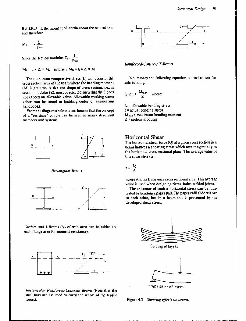
Structural .Vesign 91
P,ut X:Raz = I, the moment of inertia about the neutral axis and therefore
A .- - - -.-.
Since the section modulus Z, = -!- Ym-
Reinforced- Concreic T-Bean 1s
MU = f, x 7< = M; similarly Ma = f, x Z, = M
The maximum compressive stress (fJ will occur in the cross section area of the beam where the bending moment (M) is greatest. A size and shape of cross section, i.e., is section modulus (Z), must be selected such that the f, dots not exceed an allowable value. Allowabk: working stress values can be found in building codes CT engineering handbooks.
From the diagrams below it can be seen that the concept of a “resisting” couple can be seen in many structural members and systems.
Rectangular Beams
Girders and I-Beams (i/6 of web area can be added to each flange area for moment resistance).
N A +r o --7 - .- - - -.- -
F7
__ ,
,
P h
1’ ,
Rectangular Reinforced-Concrere Beams (Note that the steel bars are assumed to carry the whole of the tensile forces).
In summary the following equation is used to test for safe bending:
f,rf+=- where:
f, = allowable bending stress f = actual bending stress M,, = maximum bending moment Z = section modulus
Horizontal Shear The horizontal shear force (Q) at a given cross section in a beam induces a shearing stress which acts tangentially to the horizontal cross-sectional plane. The average value of this shear stress k:
where A is the transverse cross sectional area. This average value is used when designing rivets, bolts. welded joints.
The existence of such a horizontal stress can be illus- trated by bending a paper pad. The papers will slide relative to each other, but in a beam this is prevented by the developed shear stress.
SLiding of layers
Figure 4.3 Shearing effects on beams.
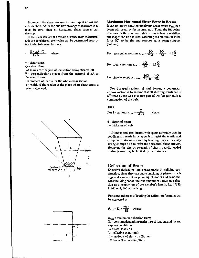
92
However, the shear stresses are not equal across the cross section. At the top and bottom edge of the beam they must be zero, since no horizontal shear stresses’ can develop.
If the shear stresses at a certain distance from the neutral axis are considered, their value can be determined accord- ing to the following formula:
where: For rectangular sections r,, = 2M 34 = $1.5~
T = shear stress Q q shear force AA = area for the part of the section being sheared off j q perpendicular distance from the centroid of AA to the neutral axis I = moment of inertia for the whole cross section b = width of the section at the place where shear stress is being calculated.
Maximum Horizontal Shear Force in Beams It can be shown that the maximum shear stress T,.,,~ in a beam will occur at the neutral axis. Thus, the following relations for the maximum shear stress in beams of differ- ent shapes can be deduced, assuming the maximum shear force (Q) to be the end reaction at a beam support (column).
For square sections r,,,, = -g = 1.5%
For circular sections rma = 3r.j5 = 3A
For I-shaped sections of steel beams, a convenient approximation is to assume that all shearing resistance is afforded by the web plus that part of the flanges that is a continuation of the web.
Thus.
P For I - sections r,,, = d x t where:
d = depth of beam t = thickness of web
If timber and steel beams with spans normally used in buildings are made large enough to resist the tensile and compressive stresses caused by bending, they are usually strong enough also to resist the horizontal shear stresses. However, the size or strength of short, heavily loaded timber beams may be limited by these stresses.
Deflection of Beams Excessive deflections are unacceptable in building con- struction, since they can cause cracking of plaster in ceil- ings and can result in jamming of doors and windows. Most building codes limit the amount of allowable deflec- tion as a proportion of the member’s length, i.e. l/ 180, 1 ! 240 or I/ 360 of the length.
For standard cases of loading the deflection formulae can be expressed as:
6 - *ax = K, x wL3
EI where:
6 max = maximum deflection (mm) K, = constant depending on the type of loading and the end support conditions W q total load (N) L = effective span (mm) E = modulus of elasticity (N/ mmr) 1 = moment of inertia (mm4)
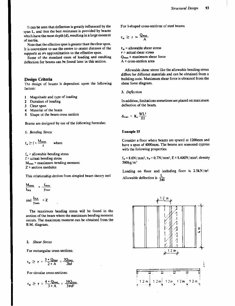
Struclural Design 93
It can be seen that deflection is greatly influenced by the span L, and that the best resistance is provided by beams which have the most depth(d), resulting in a large moment of inertia.
Note that the effective span is greater than the clear span. It is convenient to use the centre to centre distance of the supports as an approximation to the effective span.
Some of the standard cases of loading and resulting deflection for beams can be found later in this section.
Design Criteria The design of beams is dependent upon the following factors:
1 Magnitude and type of loading 2 Duration of loading 3 Clear span 4 Material of the beam 5 Shape of the beam cross section
Beams are designed by use of the following formulae:
1. Bending Stress
f, = allowable bending stress f q &ual bending stress Mm, = maximum bending moment Z = section modulus
This re!ationship derives from simpled beam theory and
& fmx =- IN A Ym-
and - hJA = z Ym=
The maximum bending stress will be found in the section of the bear where the maximum bending moment occurs. The maximum moment can be obtained from the B.M. diagram.
2. Shear Stress
For rectangular cross-sections:
Tw
For circular cross-sections:
For I-shaped cross-sections of steel beams
T,>T”. Qy
r, = allowable shear stress r = actual shear stress Q ,,,= = maximum shear force A = cross-section area
Allowable shear stress like the allowable bending stress differs for different materials and can be obtained from a building code. Maximum shear force is obtained from the shear force diagram.
3. Deflccrion
In additi,on, limitations sometimes are placed on maximum deflection of the beam.
Example 15
Consider a floor where beams are spaced at 12OOmm and have a span of 4000mm. The beams are seasoned cypress with the following properties:
fw = 8.ON/ mm*, 7w = 0.7N/mm*, E = 8.4OON/mm*, density SOOkg/ m’
Loading on floor and including floor is 2.SkN/m*. L
Allowable deflection is 240
rwzT-4xQ~ -16Um, 3xA 3rd*
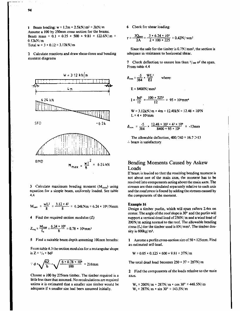
I 1 Beam loading: w q 1.2m x 2.SkN/m* = 3kN/m Assume a 100 by 250mm cross section for the beams. Beam mass = 0.1 x 0.25 * SO0 x 9.81 = 122.6N/m q
O.lZkN/ m Total w q 3 + 0.12 = 3.!2kN/m
2 Calculate reactions and draw shear-force and bending moment diagrams
W = 3.12 kN/m
l:;I:. 1”:: ll.::‘IIiI f 1,
Im
SF0 -6.24 -
BMD 2 M WI
max = 8 = 6.24 kN
3 Calculate maximum bending moment (M,,J using equation for a simple beam, uniformly loaded. See table 4.4
M WL’ 3.12 x 42 -z-z
8 8 = 6.24kNm q 6.24 x lOb/Nmm
4 Find the required section modulus (Z)
Z,, = F = 6a24 i Ioh = 0.78 x 106mm3
w
5 Find a suitable beam depth assuming 1OOmm breaths:
From table 4.3 the section modulus for a rectangular shape is Z = l/b x bd*
‘.* d +=,/y = 2,hmm
Choose a 100 by 22Smm timber. The timber required is a little less than that assumed. No recalculations are required unless it is estimated that a smaller size timber would be adequate if 1 smaller size had been assumed initially.
6 Check for shear loading:
/+=-3x 6.24~ 10’ 2 ⌧ ,oo y 22s q 0.42N/:nm*
Since the safe for the timber is 0.7N/ mm*, the section is adequate in resistance to horizontal shear.
7 Check deflection to ensure less than l/240 of the span. From table 4.4
-s WL’ where:
E = 84OON/ mm2
&i!‘= 100 x 2253 12 12
= 95 y 106mm4
W = 3.12kN/m x 4m = 12.48kN = 12.48 x !PN L=4x 103mm
6 Enill =Lx 12.48 103 4l x x x lc$ = 384 8400 x 95 x 106
-,3mm
The allowable deflection, 400/ 240 = 16.7 > 13 :. beam is satisfactory.
Bending Moments Caused by Askew Loads If beam is loaded so that the resulting bending moment is not about one of the main axes, the moment has to be resolved into components acting about the main axes. The stresses are then calculated separately relative to each axis and the totalstrem is found by adding the stresses caused by the components of the moment.
Example 16 Design a timber purlin, which will span rafters 2.4m on center. The angle of the roof slope is 30” and the purlin will support a vertical dead load of 250N,! m and a wind load of 2OON/ m acting normal to the roof. The allowable bending stress (f,,J for the timber used is 8N/ mm*. The timber den- sity is 6OOkg/ m3.
1 Assume a purlin cross-section size of SO x 12Smm. Find au estimated self-load.
W = 0.05 x 0.125 x 600 x 9.81 = 37N/m
The total dead load becomes 250 + 37 = 287N/m
2 Find the components of the loads relative to the main axes.
W, = 2OON/ m + 287N/ m x cos 30” = 448.SN/m W, = 287N/ m x sin 30’ q 143.5N/ m
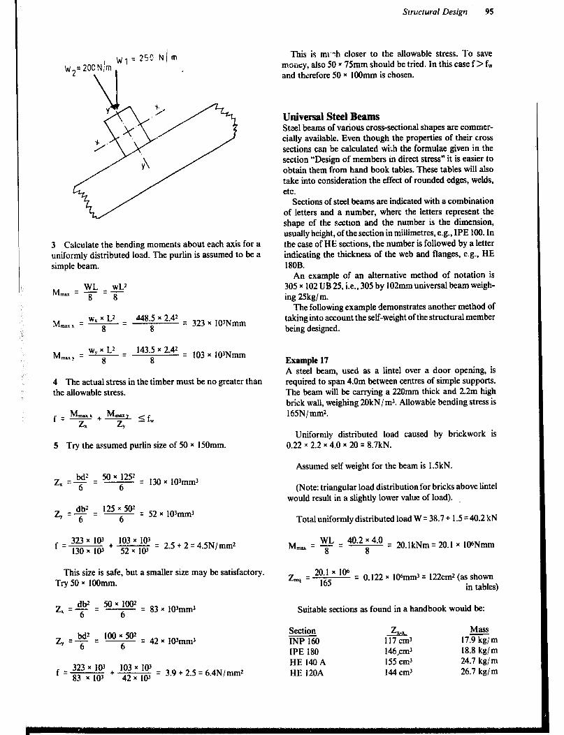
Slrmural Design 95
3 Calculate the bending moments about each axis for a uniformly distributed load. The purlin is assumed to be a simple beam.
M WL wL2 ma=-=- 8 8
w1 x L2 M,,,, I = - =
448.5 x 2.42 8 8
= 323 x 103Nmm
M mary q w, x L2 q 143.5 x 2.42
8 8 = 103 x 103Nmm
4 The actual stress in the timber must be no greater than the allowable stress.
5 Try the assumed purlin size of 50 x 150mm.
-z, = $2 = �y q 130 Y ]()3mm3
2, q $f = lEP$?T = 52 x 103~~3
f 323 x
103 + 103 x
103 = = = 130 x I@ 52 * 10’
2.5 + 2 4.5N/mm2
This size is safe, but a smaller size may be satisfactory. Try 50 x 1OOmm.
z -e = 50x1002 1. - 6
- = 83 x lO%nm3 6
323 x
103 103 x
f 103 q = = 83
+ x 103 42x 101
3.9 + 2.5 6.4N/mm2
This is mt :h closer to the allowable stress. To save money, also 50 x 75mm should be tried. In this case f > f, and therefore 50 x 1OOmm is chosen.
Universal Steel Beams Steel beams of various cross-sectional shapes are commer- cially available. Even though the properties of their cross sections can be calculated wr[h the formulae given in the section “Design of members in direct stress” it is easier to obtain them from hand book tables. These tables will also take into consideration the effect of rounded edges, welds, etc.
Sections of steel beams are indicated with a combination of letters and a number, where the letters represent the shape cf the sectron and the number is the dimension, usually height, of the section in millimetres, e.g., IPE 100. In the case of HE sections, the number is followed by a letter indicating the thickness of the web and flanges, e.g., HE 180B.
An example of an alternative method of notation is 305 x 102 UB 25, i.e., 305 by 102mm universal beam weigh- ing 25kg/ m.
The following example demonstrates another method of taking into account the self-weight of the structural member being designed.
Example 17 A steel beam, used as a lintel over a door opening, is required to span 4.0m between centres of simple supports. The beam will be carrying a 220mm thick and 2.2m high brick wall, weighing 20kN/ m3. Allowable bending stress is 165N/ mmz.
Uniformly distributed load caused by brickwork is 0.22 x 2.2 x 4.0 x 20 = 8.7kN.
Assumed self weight for the beam is 1.5kN.
(Note: triangular load distribution for bricks above lintel would result in a slightly lower value of load).
Total uniformly distributed load W = 38.7 + 1.5 q 40.2 kN
Mm = “s” - 40.2 ; 4.0 = 20.lkNm = 20.1 x 10⁶Nmm
z =20.1x10⁶ rrq 165
= 0.122 x 106mm3 = 122cmz (as shown in tables)
Suitable sections as found in a handbook would be:
IPE 180 HE14OA HE 120A
146,cm3 155 cm3 144 cm3
18.8 kg/m 24.7 kg/m 26.7 kg/m
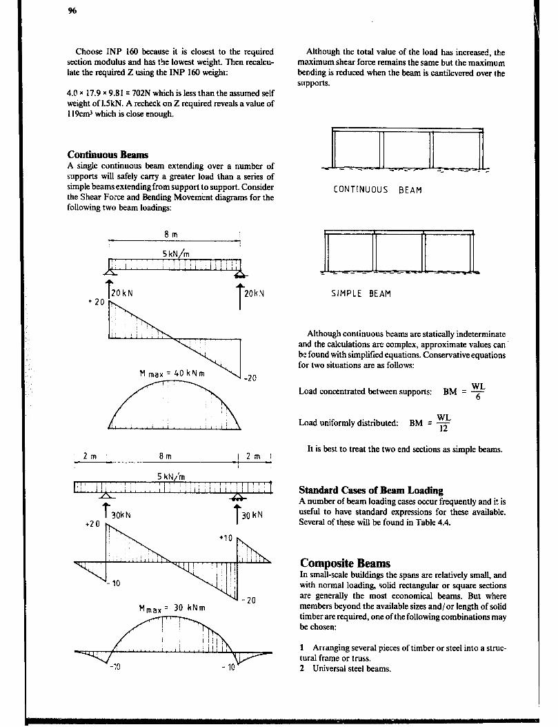
Choose INP 160 because it is closest to the required section modulus and has the lowest weight. Then recalcu- late the required Z using the INP 160 weigh::
43 x 17.9 x 9.81 = 702N which is less than the assumed self weight of 1.5kN. A recheck on Z required reveals a value of 119cmJ which is close enough.
Continuous Beams A single continuous beam extending over a number of supports will safely carry a greater load than a series of simple beams extending from support to support. Consider the Shear Force and Bending Movement diagrams for the following two beam loadings:
+2 T T 20kN 20kN
0 0 T T 20kN 20kN
M max = 40 kNm M max = 40 kNm
(-2o (-2o
2m 8m I2m (
Mmax’ 30 kNm
Although the total value of the load has increased, the maximum shear force remains the same but the maximum bending is reduced when the beam is cantilevered over the supports.
CONTINUOUS BEAM
SIMPLE BEAM
Although continuous beams are statically indeterminate and the calculations are complex, approximate values can be found with simplified equations. Conservative equations for two situations are as follows:
Load concentrated between supports: BM = E 6
Load uniformly distributed: BM = F
It is best to treat the two end sections as simple beams.
Standard Cases of Beam Loading A number of beam loading cases occur frequently and it is useful to have standard expressions for these available. Several of these will be found in Table 4.4.
Composite Beams In small-scale buildings the spans are relatively small, and with normal loading, solid rectangular or square sections are generally the most economical beams. But where members beyond the available sizes and/or length of solid timber are required, one of the following combinations may be chosen:
1 Arranging several pieces of timber or steel into a struc- tural frame or truss. 2 Universal steel beams.

Structural Design 97
Table 4.4 &am Equntions
Loading Diagram
[-jzq- j a*b:L
Total w = WL
G--l
&Ff B
Total W = 9
:-, ~-
Turd W = F
*f=+h
-
B
B
Total W = 9
A:& x .B
w w w
111
‘t L T? Rl 2
Shear Force at x: Qx ----
QA:+
Qll:+-
QA:$
W o’j=-T
QA:Kp
Qe= +: -p
-
QA=QB=W
QA=W
QA=O
PA- W
QA=O
-
QA=?
QA:?
Qe: -+
QA=$-
Q*=F
-
Bending Moment at x: Mx Deflection at x: 6x
MC = Wab L
When II = b
M =wL c 4
M WL
max=- 8
L atx=?
Mmax = 0.064 mL2
at x q 0.577L
WV Mmax’F
C8tx-L 2
MA=-WL
WL WL’ MA= m-z - - 2 2
WaZb MB--L’
WL MA-MB--E
WL WLZ -=-- MA=- 10 20
WI wL2 MB=-==-=
M WL - -* max- 6
WL - -* Mmu - 12
6 5WL’ max = -4E
L atx=- 2
WL’ Inax = 0.00652 ig
atx-0.519
6 WL’ m*=-i5iE
atx=-J= 2
&= WV 3EI
WL’ WL’ &J= 3E1-m
WL’ 6B= 30EI
6 = Wajb’ ’ 3EIL’
WLJ *’ = 384EI
6 WL’ max -%zEi
at x = 0.4751.
6 WL’ max=EEi-
6 WL”
max -3&i-
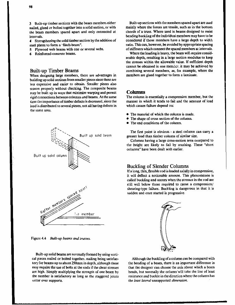
98
3 Built-up timber sections with the beam members either nailed, glued or bolted together into a solid section, or with the beam members spaced apart and only connected at intervals. 4 Strengthening the solid timber section by the addition of steel plates to form a * flitch-beam”. 5 Plywood web beams with one or several webs. 6 Reinforced-concrete beams.
Built-up Timber Beams When designing large members, there are advantages in building up solid sections from smaller pieces since these are less expensive and easier to obtain. Smaller pieces also season properly without checking. The composite beams may be built up in ways that minimize warping and permit rigid connections between columns and beams. At the same time the importance of timber defects is decreased, since the load is distributed to several pieces, not all having defects in the same area.
Built up solid beam
Figure 4.4 Built-up beams and trusses.
Built-up solid beams are normally formed by using verti- cal pieces nailed or bolted together. nailing being satisfac- tory for beams up to about 250mm in depth, although these may require the use of bolts at the ends if the shear stresses are high. Simply multiplying the strength of one heam by the number is satisfactory as long as the staggered joints occur over supports.
Built-up sections with the members spaced apart are used mainly where the forces are tensile, such as in the bottom chords of a truss. Where used in beams designed to resist bending buckling of the individual members may have to be considered if those members have a large depth to width ratio. This can, however, be avoided by appropriate spacing of stiffeners which connect the spaced members at intervals.
Where the loading is heavy, the beam will require consid- erable depth, resulting in a large section modulus to keep the stresses within the allowable value. If sufficient depth cannot he obtained in one met&&. it may be achieved by combining several members, as, fox example, where the members are glued together to form a laminate.
cohunns The column is essentially a compression member, but the manner in which it tends to fail and the amount of load which causes failure depend on:
* The material of which the column is made. 0 The shape of cross section of the column. 0 The end conditions of the column.
The first point is obvious - a steel column can carry a greater load than timber column of similar size.
Columns having a large cross-section area compared to the height are likely to fail by crushing. These “short columns” have been dealt with earlier.
Buckling of Slender Columns If a long, tt&, flexible rod is loaded axially in compression, it will deflect a noticeable amount. This phenomenon is called buckling and occurs when the stresses in the rod are s:ill well below those required to cause a compression/ shearing-type failure. Buckling is dangerous in that it is sudden and once started is progressive.
Although the buckling of a column can be compared with the bending of a beam, there is an important difference in that the designer can choose the axis about which a heam bends, but normally the column’will take the line of least resistance and buckle in the direction where the column has the least latercd unsupported dimension.

Structural Design 99
Since the loads on columns are never perfectly tial and the columns are not prfectly straight, there will always be sma!l bending moments induced in the column when it is compressed.
There may be parts of the cross section area where the sum oi the compressive stresses caused by the load on the column could reach values larger than the allowable or even the ultimate strength of the material.
Therefore the allowable compressive strength 6, is reduced by a factor kA, which depends on the slenderness ratio and the material used.
Pbw = kA x 6, x A Where: Pbw q allowable load with respect to buckling kA = reduction factor, which depends on the slenderness
ratio 6, = allowable compressive stress A = cross-section area of the column
When the load on a column is not axial but eccentric, a bending stress is induced in the column as well as a direct compressive stress. This bending stress will have to be con- sidered when desiping the column with respect to buckling.
Slenderness Ratio As stated earlier. the relationship between the length of the column, its lateral dimensions and the end fixity conditions will strongly affect the re&tance of the column to buckling. An expression called slenderness ratio has been developed to describe this relationship:
&iL=-L r r
where: A = slenderness ratio K q effective length factor, whose value depends on how the ends of the column are fmed L = length of the column
r = radius of gyration (r = i)
I= effective length of the column (K x L)
There are four types of end conditions for a column or strut:
P P e Rotatron
0
/ /
c t--’ t
side movement
I
: T
1 Total freedom of rotation and side movement - like the top of a flagpole. This is the weakest end condition.
2 Fixed in position but not in direction (pinned).
.i.p r-41,
L-+-l
/
3 Fixed in direction but not in position.
4 Fined in position and in direction.
The consideration of the t%o end conditions together results in the following theoretical values for the effective length factor. (K, = factor usually used in practice).
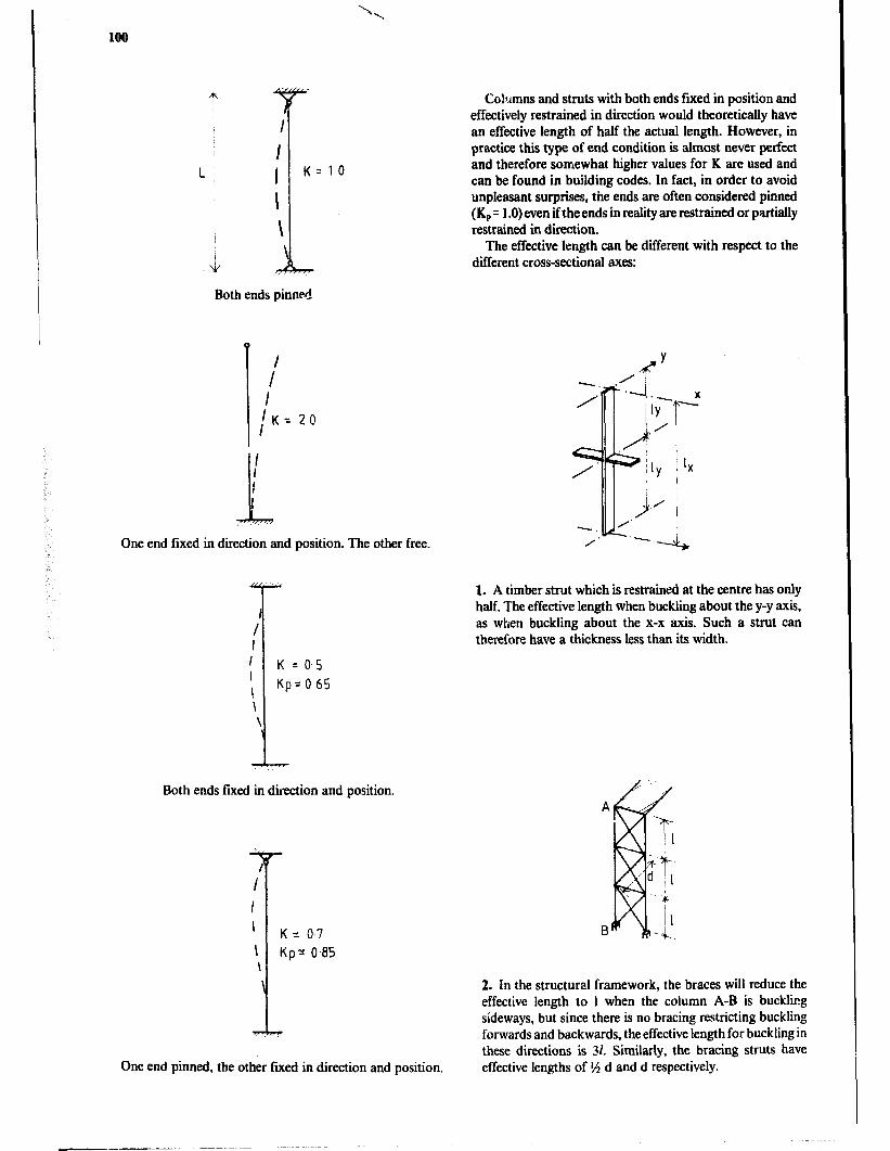
L 11 K=lO I ! I \ .i Both ends pinned
0
/
I
IK= 20 I
I
i
I I ,. I.
One end fixed in direction and position. The other free.
Both ends faed in direction and position.
Columns and struts with both ends ftxed in position and effectively restrained in direction would theoretically have an effective length of half the actual length. However, in practice this type of end condition is almost never perfect and therefore somewhat higher values for K are used and can be found in building codes. In fact, in order to avoid unpleasant surprises, the ends are often considered pinned (KP = 1 .O) even if the ends in reality are restrained or partially restrained in direction.
The effective length can be different with respect to the different cross-sectional axes:
1.
7
-. / 1. A timber strut which is restrained at the centre has only half. The effective length when buckling about the y-y axis, as when buckling about the x-x axis. Such a strut can therefore have a thickness less than its width.
\ Kpr 0.85 \
i
2. In the structural framework, the braces will reduce the effective length to 1 when the column A-B is buckling sideways, but since there is no bracing restricting buckliig forwards and backwards, the effective length for buckling in these directions is 31. Similarly, the bracing struts have
One end pinned, the other fured in direction and position. effective lengths of l/i d and d respectively.
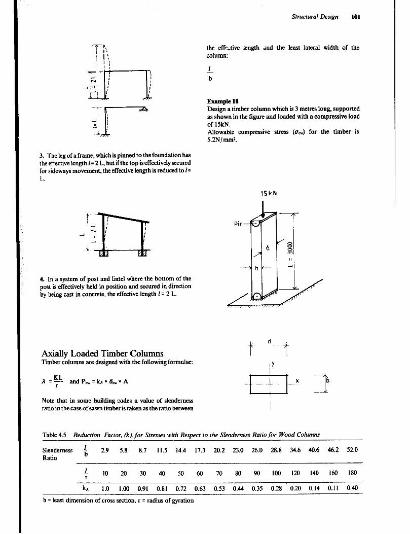
/ it the effe;tive length and the least lateral width of the column:
1
a
Example 18 Design a timber cohmm which is 3 metres long, supported as shown in the figure and loaded with a compressive load of 15kN. Allowable compressive stress (oNI) for the timber is 52N/mm2.
Structural Design 101
3. The leg of a frame, which is pinned to the foundation has the effective length I= 2 L, but if the top is effectively secured for sideways movement, the effective length is reduced to I= 1 1.
15kN
4. In a system of post and lintel where the bottom of the post is effectively held in position and secured in direction by being cast in concrete, the effective length I= 2 L.
Axially Loaded Timber Columns Timber columns are designed with the following formulae:
A q KL andP r bw =lux6,xA
Note that iu some building codes a value of slenderness ratio in the case of sawn timber is taken as the ratio between
Table 4.5 Reduction Factor, fi), for Stresses with Respect to the Slenderness Ratio for Wood Columns
Slenderness t 2.9 5.8 8.7 11.5 14.4 17.3 20.2 23.0 26.0 28.8 34.6 40.6 46.2 52.0 Ratio
r 10 20 30 40 50 60 70 80 90 100 120 140 160 180 r
1.0 1.00 0.91 0.81 0.72 0.63 0.53 0.44 0.35 0.28 ’ 0.20 0.14 0.11 0.40
b = least dimension of cross section, r = radius of gyration
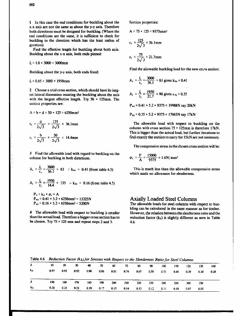
102
1 In this case the end conditions for buckling about the x-x axis are not the same as about the y-y axis. Therefore both directions must be designed for buckling. (Where the end conditions are the same, it is sufficient to check for buckling in the direction which .has the least radius of gyration).
Find the effective length for buckliig about both axis. Buckling about the x-x axis, both ends pinned:
I,= 1.0~3000=3000mm
Buckling about the y-y axis, both ends fixed:
ly q 0.65 x 3080 = 19SOmm
2 Choose a trial cross section, which should have its larg- est lateral dimension resisting the buckling about the axis with the largest effective length. Try SO x 12Smm. The section properties are:
A=bxd=SOx 125=62SOmmz
q - ~125 = 361mm d
24 .
z-=x = 144mm b rk 2\/5 2a -
3 Find the allowable load with regard to buckling on the column for buckling in both directions.
+++3 .-. k~. = 0.41 (from table 4.5)
.‘. kl, = 0.16 (from table 4.5)
P, = kA x uc x A P, q 0.41 x 5.2 x 62SOmm* = 1332SN P, q 0.16 x 5.2 x 62SOmm* = 52OON
4 The allowable load with respect to buckling is smaller than the actual load. Therefore a bigger cross section has to be chosen. Try 75 x 125 mm and repeat steps 2 and 3.
Section properlies:
A = 75 8 125 = 937Smmz
125 =- =36.lmm
TX 2J3
7s =- =21.7mm
ry 2J3
Find the allowable buckling load for the new cr%qs section:
83 gives G. q 0.41
A, = 4 = 1950 .- - ry 21 7 90 gives lily = 0.35
P wx = 0.41 x 5.2 x 9375 = 19988N say 20kN
P, q 0.35 x 5.2 x 9375 = 17063N say 17kN
The allowable load with respect to buckling on the column with cross section 75 x 12Smm is therefore 17kN. This is bigger than the actual load, but further iterations to find exactly the section to carry the 1SkN are not necessary.
The compressive stress in the chosen cross section will be:
F 15000 UC q ⌧ = 937s -= 1.6N/mm*
This is much less than the allowable compressive stress which made no allowance for slenderness.
Axially Loaded Steel Columns The allowable loads for .steel columns with respect tc buc- kling can be calculated in the same manner as for timber. However, the relation between the slenderness ratio and the reduction factor (G) is slightly different as seen in Table 4.6.
Table 4.6 Reduction Factor (IcA) for Stresses with Respect IO the Slenderness Ratio for Steel Columns
A IO 20 30 40 50 60 10 80 90 loo 110 120 130 I40
kr 0.97 0.95 0.92 0.90 0.86 0.81 0.74 0.67 0.59 0.51 0.45 0.39 0.34 0.30
A IM I60 170 180 I90 200 210 220 230 240 250 300 350
h 0.26 0.23 0.21 0.19 0.!7 0.15 0.14 0.13 0.12 0.1 I 0.10 0.07 0.05

Structural Design 103
Example 19 Calculate the safe load on a hollow square steel stanchion, whose external dimensions are 120 x 120mm. The walls of the column are 6mm thick and the allowable compressive stress UcW = lSON/mm*. The column is 4 metres high and both ends are held effectively in position, but one is also restrained in direction.
The effective length of the column I q 0.8SL = 0.85 x 4060 = 34UOmm.
A =L=J%!!?-• r 46.6
73 giving KA = 0.72 by interpolation
Example 20 A concrete column, with an effective length of 4 metres has a cross section of 300 x 400mm. Calculate the allowable axial load, if a nominal concrete mix 1:2:4 is to be used.
Slenderness ratio t = $& = 13.3
Hence table gives P, = 3.47 N/mm* by interpolation. PW=P,xA=3.47x300x400=416.4kN.
Eccentrically Loaded Timber and Steel Columns Where a column is eccentrically .loaded, two load effects have to be considered:
The axial compressive stress caused by the load. The bending stresses caused by the eccentricity of the load.
Obviously, by the law of superposition, the added stresses of the two load affects must be below the allowable stress.
P, = kl x ocew * A = 0.72 x 150 (1202 - 1082) q 29SkN.
Therefore j$- f
+ - 5 1 i.e. cw
f w
Axially Loaded Concrete Columns Most building codes permit the use of plainconcrete only in short columns, i.e., columns where the ratio of the effective length to least lateral dimension does not exceed 15, i.e. l/r I 15. If the slenderness ratio is between 10 and IS, the allowable compressive strength must be reduced. The tables of figures relating to l/b in place of a true slenderness ratio are only approximate, since radii of gyration depend on both b and d values in the cross section, and must be used with caution. In the case of a circular column:
b:$x & = 0.87D. where
D = the diameter of the column.
Table 4.7 Permissible Compressive Stress (P‘.,J in Concrete for Columns (N/md)
concrete Mii Slenderness ratio, l/b 5 IO II I2 I3 I4 I5
PnsClibHl Cl0 3.2 3.1 3.0 2.9 2.8 2.7 Cl5 3.9 3.8 3.7 3.6 3.5 3.4 c20 4.8 4.6 4.5 4.3 4.2 4.1
Nominal 1:3:5 3.1 3.0 2.9 2.8 2.7 2.6 I :2:4 3.8 3.7 3.6 3.5 3.4 3.3 l:l.5:3 4.7 4.5 4.4 4.2 A. I A0
Higher values of stresses may be permitted, depending on levels of super- vision work.
Higher values of stress may be pe,rmitted, depending on levels of supervision of work.
axial camp. stress bending stress ( , allowable camp. stress + allowable bending stress -
kA xo;m f, + f 5 1 which can be transferred to
Example 21 Determine within 2Smm the required diameter of a timber post loaded as shown in the figure. The bottom of the post is fixed in both position and direction by being cast in a concrete foundation. Allowable stresses for the timber used are a, q 9 N/mm2 and f, q ION/mm*.
! P=30kN

104
The load of SkN on the cantilever causes a bending moment of M q F x e = SkN x 0.5m = 2.5kNm in the post below the cantilever.
The effective length of the post = L x K q 3000 x 2.1 = 6300mm. Try with a post having the diameter 200mm.
The cross sectional properties are:
KD3 Z q 32 =
TX2003 32 q 78540Omm*
r=D=200- jo- 4 4-
1 6300 The slenderness ratio = r= T= 126
interpolation in Table 4.5 gives kn = 0.18
30000 9 +-- 2.5x106 = 0.18 x 31400 10 785400 8.17Njmmz5 9N/mm*
If the post has a diameter of 2OOmm, it will be able to carry the loads, but !he task was to determine the diameter within 2Smm. Therefore a diameter of 17Smm must also be tried.
A= 6300 m= 144 kA =0.13
30000 9 2.5 x l@ x - 0.13 x 24050 ‘lo = 167480 23N/mm* > 9N/mm2
This diameter is too small, so a diameter of 200mm should be chosen. It will be appreciated that the choice of effective length based on end ftity has a great effect on the solution.
Plain and Centrally Reinforced Concrete walls Basically walls are designed in the same manner as columns, but there ate a few differences. A wall is distinguished from a column by having a length which is more than five times the thickness.
Plain concrete walls should have a minimum thickness of 1OOXtUll.
Where the load on the wall is eccentric, the wall must have centrally placed reinforcement of at least 0.2% of the cross section area if the eccentricity ratio e/b exceeds 0.20. This reinforcement may not be included in the load- carrying capacity of the wall.
Many agricultural buildings have walls built of blocks or bricks. The same design approach as that shown for plain concrete with axial loading can be used. The maximum allowable compressive stresses must be ascertained, but the reduction ratios can be used as before.
Example 22 Determine the maximum allowable load ?p- metre of a 120mm thick wall, with an effective height of 15.8 metres and made from concrete grade CIS, a) when the load is central, b) when the load is eccentric by 20mm.
I Slenderness ratio b - = E = 23.3
a Interpolation gives:
P,=2.8- v (2.8 - 2.0) = 2.27N/mm2 = 2.27MN/m*
Allowable load P, = A x Pew = 1.0 x 0.12 x 2.27 x 106 = 272.4kN/m wall
b Ratio of eccentricity 5 = go = 0.167
A double interpolation gives:
P, = l.O6N/mm* = UkiMN/m*
1.06 x 1w Allowable load P, = 1 .O x 0.12 x - - loo0 - 127.2kN/m wall
Central reinforcement is not required since p < 0.20
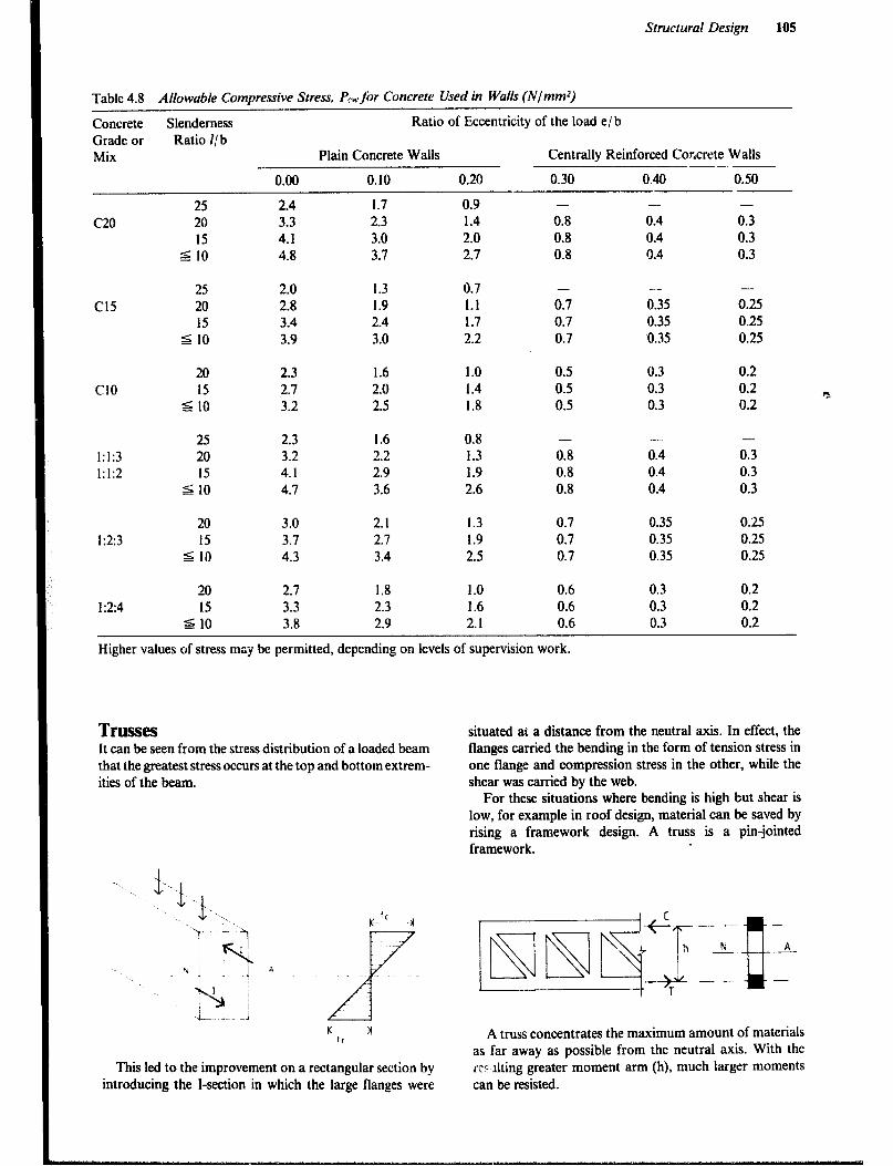
Structural Design 10s
Table 4.8 Allowable Compressive Stress. PC&. for Concrete Used in Walls (NlmmJ)
Concrete Slenderness Ratio of Eccentricity of the load e/b Grade or Ratio l/b Mix Plain Concrete Walls Centrally Reinforced Concrete Walls --. -
0.00 0.10 0.20 0.30 0.40 0.50
2.4 3.3 4.1 4.8
1.7 2.3 3.0 3.7
1.3 1.9 2.4 3.0
0.9 1.4 2.0 2.7
-
0.8 0.8 0.8
-
0.4 0.4 0.4
-
0.3 0.3 0.3
2.0 2.8 3.4 3.9
0.7 1.1 1.7 2.2
1.0 1.4 1.8
- -
0.35 0.25 0.35 0.25 0.35 0.25
-
0.7 0.7 0.7
2.3 2.7 3.2
1.6 2.0 2.5
1.6 2.2 2.9 3.6
0.5 0.5 0.5
0.3 0.3 0.3
0.2 0.2 0.2
20 Cl0 15
d IO
25 1:1:3 20 1:1:2 15
s 10
2.3 3.2 4.1 4.1
0.8 1.3 1.9 2.6
- -
0.8 0.4 0.8 0.4 0.8 0.4
-
0.3 0.3 0.3
2.1 2.7 3.4
1.3 1.9 2.5
1.0 1.6 2.1
0.7 0.35 0.25 0.7 0.35 0.25 0.7 0.35 0.25
20 1:2:3 15
5 IO
3.0 3.7 4.3
20 1:2:4 15
5 IO
2.7 3.3 3.8
1.8 2.3 2.9
0.6 0.3 0.2 0.6 0.3 0.2 0.6 0.3 0.2
Higher values of stress may be permitted, depending on levels of supervision work.
TWS!ZS It can be seen from the stress distribution of a loaded beam that the greatest stress occurs at the top and bottom extrem- ities of the beam.
situated at a distance from the neutral axis. In effect, the flanges carried the bending in the form of tension stress in one flange and compression stress in the other, while the shear was carried by the web.
For these situations where bending is high but shear is low, for example in roof design, material can be saved by rising a framework design. A truss is a pin-jointed framework.
-
A ..-
-- -
N
--
A truss concentrates the maximum amount of materials as far away as possible from the neutral axis. With the rc~lting greater moment arm (h), much larger moments can be resisted.
This led to the improvement on a rectangular section by introducing the l-section in which the large flanges were

106
Resistance of a truss at a section is provided by:
M = C x h = T x h, where C = T in parallel cords and:
C = compression in the top chord of the truss. T = tension in bottom chord of a simply supported truss. h = vertica! height of truss section.
If either C, T or h can be increased, then the truss will be capable of resisting heavier loads. The value of h can be increased by making a deeper truss.
Allowable C or T stresses can be increased by choosing a larger cross section for the chords of the truss, or by chang- ing to a stronger material.
A framework or truss can be considered as a beam with the major part of the web removed. This is possible where bending stresses are more signifcant than shear stresses. The simple beam has aconstant section along its length, yet the bending and shear stresses vary. The truss, made up of a number of simple members, can be fabricated to take into account this change in stress along its length.
The pitched-roof truss is the best example of this, although the originJl shape was probably designed to shed rain water. Roof trusses consist of sloping rafters which meet at the ridge, a main tie connecting the feet of the rafters, and internal bracing members. They are used to support a roof covering in conjunction with purhns, which are members laid longitudinally aLross the rafters, the roof covering being attached to the purlins. The arrangement of internal bracing depends on the span. Rafters are normally divided into equal lengths, and ideally, the purlins are sup- ported at the joints, so that the rafters are only subjected to axial forces. This is not always practicable, since purlin spacing is dependent on the type of roof covering. When the purlins are not supported at the panel joints, the rafter members must be designed for bending as well as axial force. See Figure 4.5.
The internal bracing members of a truss should be trian- gulated and, as far as possible, be arranged so that long members are in tension and compression members are short to avoid buckling problems.
The outlines in Figure 4.6 give typical forms for various spans The thick lines indicate struts.
The lattice girder, also called a truss, is a plane frame of open web construction, usually having parallel chords or booms at top and bottom. There are two main types, the N (or Pratt) girder and the Warren girder. They are very useful in long-span construction, in which their small depth-to- span ratio. generally about I/ to to ‘I 14, gives them a distinct advantage over roof trusses.
Steel and timber trusses are usually designed assuming pin-jointed members. In practice, timber trusses are assembled with bolts, nails or special connectors, and steel trusses are bolted, riveted or welded. Although these rigid joints impose secondary stresses, it is seldom necessary to consider them in the design procedure. The following steps should be considered when designing a truss:
1 Select genera! layout of truss members and truss spacing. 2 Estimate external loads to be applied including self- weight of truss, purlins and roof covering, together with wind loads. 3 Determine critical (worst combinations) loading. It is usual to consider dead loads alone, and then dead and imposed loads combined. 4 Analyze framework to find forces in ah members. 5 Select material and section to produce in each member a stress value which does not exceed the permissible value. Particular care must be taken with compression members (struts), or members normally in tension but subject to stress reversal due to wind uplift.
Unless there are particular constructiona! requirements, roof trusses should, as far as possible, be spaced to achieve a minimum of weight and economy of materials used in the total roof structure. As the distance between trusses is increased, the weight of the purlins tends to increase more rapidly than that of the trusses. For spans up to about 20m, the spacing of steel trusses is likely to be about 4m, and in the case of timber, 2m.
The pitch, or slope, of a roof depends on locality, imposed loading and type of covering. Heavy rainfall may require steep slopes for rapid drainage; a slope of 22” is common for corrugated steel and asbestos roofing sheets. Manufacturers of roofing material usually make recom- mendations regarding suitable slopes and fixings.
Ridge
Bendmg
Figure 4.5 Trurs components.

Structural Design
W or BELGIAN TRUSS
FAN TRUSS PRATT TRUSS
UPTO 12m ssan
N -GIRDER WARREN GIRDER
LONG SPAN CONSTRUCTION
Figure 4.6 Qpes of trusses.
To enable the designer to cidermine the maximum design load for each member, the member iorces can be evaluated either by calculation or graphical means, and the results tabulated as shown:
A simplified approach can be used if the intention is to use a common section throughout. Once the layout has been chosen, the member which will carry the maximum load can be established. An understanding of the problems of instability of compression members will lead the designer to concentrate on the top chord or rafter members. A force diagram or method of sections can then be used to deter- mine the load on these members, and the necessary sire.
Example 23 A farm building comprised of block walls carries steel roof trusses over a span of am. Roofing sheets determine the purlm spacings.
LAYOUT CHOSEN
(nodes at purlin points I
Assume a force analysis shows maximum rafter forces of approximately 50kN in compression (D + I) and 30kN in tension (D + W), outer main tie member 50kN tension (D + I) and 30kN compression (D + W). A reversal of forces due to the uplift action of wind will cause the outer main tie member to have 50kN of tension and 30kN of compression.
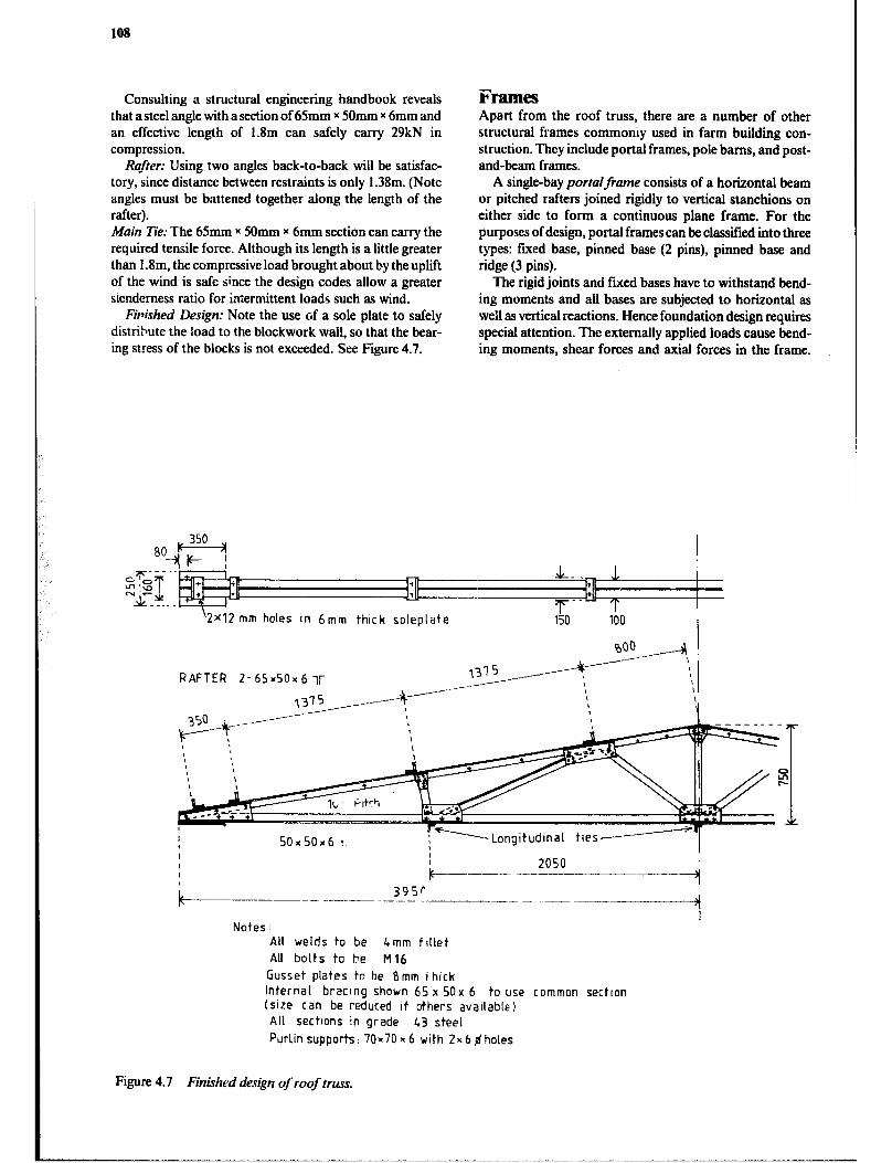
108
Consulting a structural engineering handbook reveals that a steel angle with a section of 65mm x 5Omm x 6mm and an effective length of 1.8m can safely carry 29kN in compression.
Rujkr: Using two angles back-to-back will be satisfac- tory, since distance between restraints is only 1.38m. (Note angles must be battened together along the length of the rafter). Main Tie: The 65mm x 50mm x 6mm section can carry the required tensile force. Although its length is a little greater than 1 .Sm, the compressive load brought about by the uplift of the wind is safe since the design codes allow a greater sienderness ratio for intermittent loads such as wind.
Finished Design: Note the use of a sole plate to safely distribute the load to the blockwork wall, so that the bear- ing stress of the blocks is not exceeded. See Figure 4.7.
Frames Apart from the roof truss, there are a number of other structural frames commoniy used in farm building con- struction, They include portal frames, pole barns, and post- and-beam frames.
A single-bay portalframe consists of a horizontal beam or pitched rafters joined rigidly to vertical stanchions on either side to form a continuous plane frame. For the purposes of design, portal frames can be classi.t%d into three types: fared base, pinned base (2 pins), pinned base and ridge (3 pins).
The rigid joints and fued bases have to withstand bend- ing moments and all bases are subjected to horizontal as well as vertical reactions. Hence foundation design requires special attention. The externally applied loads cause bend- ing moments, shear forces and axial forces in the frame.
‘2x12 mm holes In 6mm thick soleplate
RAFTER 2- 65x50~ 6 ll-
I Notes :
All welds to be &mm fillet All bolts to be Ml6
Gusset plates to be Bmm i hick Internal bracing shown 65 x 50x 6 to use common sectton (size can be reduced if others avaIlable All sections in grade 43 steel
Purlin supports: 70-70 x 6 with 2x 6 $ holes
Figure 4.7 Finkhed design of roof truss.
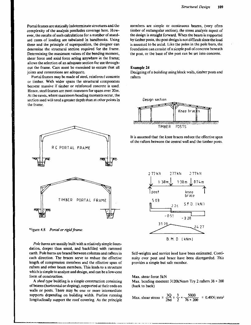
Portal frames are statically indeterminate structures and the complexity of the analysis precludes coverage here. How- ever, the results of such calculations for a number of stand- ard cases of loading are tabulated in handbooks. Using these and the principle of superposition, the designer can determine the structural section required for the frame. Determining the maximum values of the bending moment, shear force and axial force acting anywhere in the frame; allows the selection of an adequate section for use through- out the frame. Care must be exercised to ensure that ail joints and connections are adequate.
Portal frames may be made of steel, reinforced concrete or timber. With wider spans the structural components become massive if timber or reinforced concrete is used. Hence, steel frames are most common for spans over 20m. At the eaves, where maximum bending moments occur, the section used will need a greater depth than at other points in the frame.
;::14..:::1:
TIMBER PORTAL FRAME
?gure 4.8 Portal or rigidframe.
Pole barns are usually built with a relatively simple foun- dation, deeper than usual, and backfiiied with rammed earth. Pole barns are braced between columns and rafters in each direction. The braces serve to reduce the effective length of compression members and the effective span of rafters and other beam members. This leads to a structure which is simple to analyze and design, and can be a low-cost form of construction.
A shed type building is a simple construction consisting of beams (horizontal or sloping), supported at their ends on wails or posts. Ihere may be one or more intermediate supports depending on building width. Purlins running longitudinally support the roof covering. As the principle
Structural Design 109
members are simple or continuous beams, (very often timber of rectangular section). the stress analysis aspect of the design is straight forward. When the beam is supported by timber posts. the post design is not difficult since the load is assumed to be axial. Like the poles in the pole barn, the foundation can consist of a simple pad of concrete beneath the post, or the base of the post can be set into concrete.
Example 24 Designing of a building using block walls, timber posts and rafters
Oeslon section
TIMBER POSTS
It is assumed that the knee braces reduce the effective span of the rafters between the central wall and the timber posts.
277kN 277kN 2 77kN
? post knee T brace
5 03 22L SF0 IkN)
1 . 1
B. M. 0 I kNm)
Self-weights and service load have been estimated. Conti- nuity over post and brace have been disregarded. This provides a simple but safe member.
Max. shear force 5kN Max. bending moment 3 120kNmm Try 2 rafters 38 x 200 (back to back)
Max. shear stress = 2 = -$- x 7:Tm = 0.49N/mm2
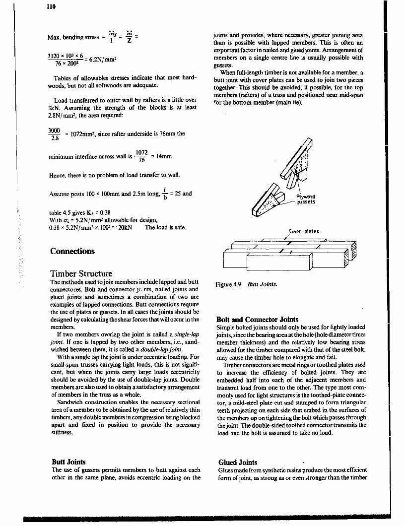
110
Max, bending stress = y = f =
3120 x 103 x 6 76x2002
= 6.2N/mm2
Tables of allowables stresses indicate that most hard- woods, but not all softwoods are adequate.
Load transferred to outer wall by rafters is a little over 3kN. Assuming the strength of the blocks is at least 2.8N/ mm2, the area required:
3000 - 2.8
= 1072mm2, since rafter underside is 76mm the
1072 minimum interface across wall is -
76 = 14mm
Hence, there is no problem of load transfer to wall.
Assume posts 100 x 1OOmm and 2Sm long, $ = 25 and
table 4.5 gives KA = 0.38 With crC = 5.2N/mm2 allowable for design, 0.38 x 52N/mm2 x 1002 = 2OkN The load is safe.
Connections
Timber Structure The methods used to join members include lapped and butt connectores. Bolt and connector scats, nailed joints and glued joints and sometimes a combination of two are examples of lapped connections. Butt connections require the use of plates or gussets. In all cases the joints should be designed by calculating the shear forces that will occur in the members.
If two members overlaE the joint is called a single-lap joint. If one is lapped by two other members, i.e., sand- wiched between them, it is cakd a double-lap join?.
With a single lap the joint is under eccentric loading. For small-span trusses carrying light loads, this is not sign& cant, but when the joints carry large loads eccentricity should be avoided by the use of double-lap joints. Double members are also used to obtain a satisfactory arrangement of members in the truss as a whole.
Sandwich construction enables the necessary sectional area of a member to be obtained by the use of relatively thin timbers, any double members in compression being blocked apart and fmed in position to provide the necessary stiffness.
Butt Joints The use of gussets permits members to butt against each other in the same plane, avoids eccentric loading on the
joints and provides, where necessary, greater joining area than is possible with lapped members. This is often an important factor in nailed and giued joints. Arrangement of members on a single centre lime is usually possible with gussets.
When full-length timber is not available for a member, a butt joint with cover plates can be used to join two pieces together. Thii should be avoided, if possible, for the top members (rafters) of a truss and positioned near mid-span for the bottom member (main tie).
r
&
.p.-.. PtpKOd
y. . . -- gussets I :
,/
Cover plates / 1
Figure 4.9 Butt Joints.
Bolt and Connector Joints Simple bolted joints should only be used for lightly loaded joints, since the bearing area at the hole (hole diameter times member thickness) and the relatively low bearing stress allowed for the timber compared with that of the steel bolt, may cause the timber hole to elongate and fail.
Timber connectors are metal rings or toothed plates used to increase the efficiency of bolted joints. They are embedded half into each of the adjacent members and transmit load from one to the other. The type most com- monly used for tight structures is the toothed-plate connec- tor, a mild-steel plate cut and stamped to form triangular teeth projecting on each side that embed in the surfaces of the members up on tightening the bolt which passes through the joint. The double-sided toothed connector transmits the load and the bolt is assumed to take no load.
Glued Joints , Glues made from synthetic resins produce the most efficient form of joint, as strong as or even stronger than the timber

Structural Design 111
joined, and many are immune to attack by dampness and decay. With this type of joint all contact surfaces must be planed smooth, and the necessary pressure provided during setting of the glue. Bolts or nails which act as cramps are often used and left in place.
The members may be glued directly to each other using lapped joints or single-thickness construction may be used by the adoption of gussets. As with nailed joints, lapped members may not provide sufftcient gluing area and gussets must then be used to provide the extra area.
Glued joints are more often used when trusses are pre- fabricated because control over temperature, joint fit and ciamping pressure is essential. For home use glue is oftne used together with nail joints.
Plywood gusset
Figure 4.11 l%uss gussets.
Figure 4.10 Double sided Toothed Plate connector.
Nailed Joints Joining by nails is the least efficient of the three methods referred to, but is an inexpensive and simple method, and can be improved upon by using glue in combination with the nails.
When trusses are pm-fabricated in factories, nailing plates are often used to connect the member. These fasten- ers come in two types:
1 A thin-gauge plate called a pierced plate fastener, which has holes punched regularly over its surface to receive nails. The pierced plate can also be used for on-site fabrication. 2 A heavier plate with teeth punched from the plate and bent up 90 degrees, called a toothed-plate fastener, or con- nector. The type, in which the teeth are an integral part of the plate, must be driven in by a hydraulic press or roller.
Pierce plate fastener
Toothed plate fastener
Figure 4.1.X h:qiling plates for truss construction.
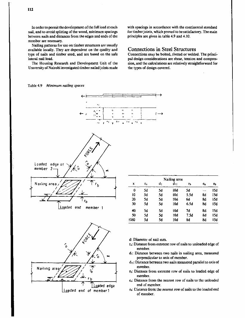
112
In order to permit thedevelopment of the full load at each nail, and to avoid splitting of the wood, minimum spacings between nails and distances from the edges and ends of the member are necessary.
Nailing patterns for use on timber structures are usually available locally. They are dependent on the quality and type of nails and timber used, and are based on the safe lateral nail load.
The Housing Research and Development Unit of the University of Nairobi investigated timber nailed joints made
with spacings in accordance with the continental standard for timberjoints, which proved to be satisfactory. The main principles are given in table 4.9 and 4.10.
Connections in Steel Strvctures Connections may be bolted, riveted or welded. The princi- pal design considerations are shear, tension and compres- sion, and the calculations are relatively straightfotward for the types of design covered.
Table 4.9 Minimum nailing spaces
hded end member 1
we- I
I
1‘T_ Lodded edga hded end of member1
Nailing area X r, dl dll l-b e. eb
0 5d 5d 1Od IO 5d 5d 1Od 20 5d 5d 1Od 30 5d 5d 1Od
5d -- 15d 5.5d 8d 15d 6d 86 15d 6.5d 8d 15d
40 5d 5d 1Od 7d 8d 15d 50 5d 5d 1Od 7.5d 8d 15d
SO 5d 5d 1Od 8d 8d 15d
d: Diameter of nail mm. r,: Distance from extreme row of nails to unloaded edge of
member. dl: Distance between two nails in nailing area, measured
perpendicular to axis of member. dl I: Distance between two nails measured parallel to axis of
member. rb: Distance from extreme row of nails to loaded edge of
member. e,: Distance from the nearest row of nails to the unloaded
end of member. eb: Distance from the nearest row of nails to the loaded end
of member.
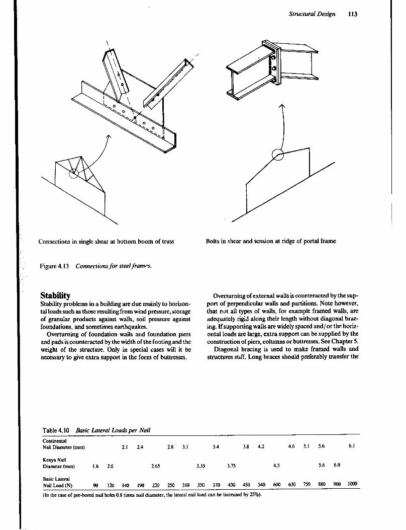
Structural Design 113
Connections in single shear at bottom boom of truss Rolts in shear and tension at ridge of portal frame
Figure 4.13 ConnectiomJor steel frames.
Stability Stability pioblems in a building are due mainly to horizon- tal loads such as those resulting from wind pressure, storage of granular products against walls, soil pressure against foundations, and sometimes earthquakes.
Overturning of foundation walls and foundation piers and pads is counteracted by the width of the footing and the weight of the structure. Only in special cases will it be necessary to give extra support in the form of buttresses.
Table 4.10 Basic Lateral Loauk per Nail
Overturning of external walls is counteracted by the sup- port of perpendicular walls and partitions. Note however, that not all types of walls, for example framed wails, are adequately rigid along their length without diagonal brac- ing. If supporting walls are widely spaced and/ or the horiz- ontal loads are large, extra support can be supplied by the construction of piers, columns or buttresses. See Chapter 5.
Diagonal bracing is used to make framed walls and structures std Long braces should preferably transfer the
Continental Nail Diameter (mm) 2.1 2.4 2.8 3.1 3.4 3.8 4.2 4.6 5.1 5.6 6.1
Kenya Nail Diameter (mm) 1.8 2.0 2.65 3.35 3.75 4.5 5.6 6.0
Basic Lateral Nail Load (IV) 90 I20 I40 I90 220 250 310 350 370 430 450 540 600 630 75!l 880 960 1000
(In the case of pm-bored nail holes 0.8 times nail diameter, the lateral nail load can be increased by 25%).

114
load with a tensile stress to avoid buckling. Braces are usually supplied in pairs, i.e., on both diagonals, so that one will always be in tension independent of wind direction.
If the framed wall is covered with a sheet material, like plywood, chipboard or metal sheets, the lateral forces on the frame can be counteracted by shear in the sheets. This design requires thal the sheets to be securely fixed to the frame, both horizontally and vertically. The sheets must also be strong enough to resist buckling or failure through shear.
Shact mterial thoroughly fmcd to the frame
MZSONY and concrete walls which are stiff and capable of resisting lateral wind loading are called shear walls.
Portal or rigid frame buildiigs are normally stable later- ally, when ;he wind pressure acts on the long sides. How- ever, when the wind loads occur at the gable ends, the frames may need extra support from longitudinal bracing. Tension rods ;~re frequently used.
Figure 4.14 Bracing for portal frame.
Post-and-beam or shed-frame buildings will, in most cases, require wind bracing, both along and across the building since there are no rigid co~ections at the top of the wall to transfer loads across and along the building. The same applies to buildings emploving roof trusses. End brac- ing should be installed.
Walls with long spans between the supporting crosswalk, partitions or buttresses tend to bend inwards due to wind load or outwards if bulk grain or other produce is stored against the wall. At the bottom of the wall this tendency is counteracted by the rigidity of the foundation(designed not to slide) and the support of a floor structure. The top of the wall is given stability by the support of the ceiling or roof
. structure or a specially designed wall beam which is securely anchored to the wall.
The designer must consider the ability of the building to withstand horizontal loading from any and all directions, without unacceptable deformation.
Retaining Walls
Wall Failure Walls are commonly used to retain soil on sloping sites, water in a pond or bulk products within a storage area. There are several limiting conditions which, if exceeded, can lead to the failure of a retaining wall. Each must be addressed in designing a wall.
1 Overturning - This occurs when the turning moment due to lateral forces exceeds that due to the self-weight of, the wall. The factor of safety against overturning should be at least two.
--- ---_ - - - - - - _ _ -----. - ---- - ---_- -----
pl p 7
r//l///
2 Hiding - The wall will slide if the lateral thrust exceeds the frictional resistance developed between the base of the wall and the soil. The factor of safety against sliding should be about two.
I Sliding /
/

Structural Design 115
3 Bearing on Ground - The normal pressure bet ween the base of the wall and the soil beneath can cause a bearing failure of the soil, if the ultimate bearing capacity is exceeded. Usually the allowable bearing pressure will be one-third of the ultimate value. Note that the pressure distribution across the base is not constant.
Bearrng pressure
Gravity walls and dams are dependent on the effect of gravity, largely from self-weight of the wall itself, for stabil- ity. Other :ypes of walls rely on a rigid base, combined with a wall designed against bending to provide an adequate structure.
Tension bending failure
4 Rotational Slip - The wall and a large amount of the retained material rotate about some point 0, if the shear rebistance developed along a circular arc is exceeded. The an:+!yPis is too complex to include here.
Pressure Exerted by Retained Material
\ \
5 Wall Material Failure - The structure itself must be capable of withstanding the internal stresses set up, tha: is, the stresses must not exceed allowable values. Factors of safety used here depend on the material and the level of the designer’s knowledge in respect to the loads actually app lied. Naturally, both shear and bending must be considered, but the most critical condition is likely to be tension failure cf the ‘front’ face.
Joint failure in blockwor h
Liquid Pressure The pressure in a liquid is directly proportional to both the depth and the specific weight of the liquid (w) which is the weight per unit volume.
w = m (N/ m3) where: p = demty of liquid (kg/ m3) g = gravitational acceleration (9.8 1 m/ s2)
- Free surface
------ Liquid
Ii
The pressure at a given depth acts equally in all direc- tions, and the resultant force on a dam or wall face is normal to the face. The pressure due to the liquid can be treated as a distributed load with linear variation in a triangular load form, having a centroid two-thirds of the way down the wet face.
.
p = pgH = wH (N/mr) and: 2
P = wT acting at a depth of f H
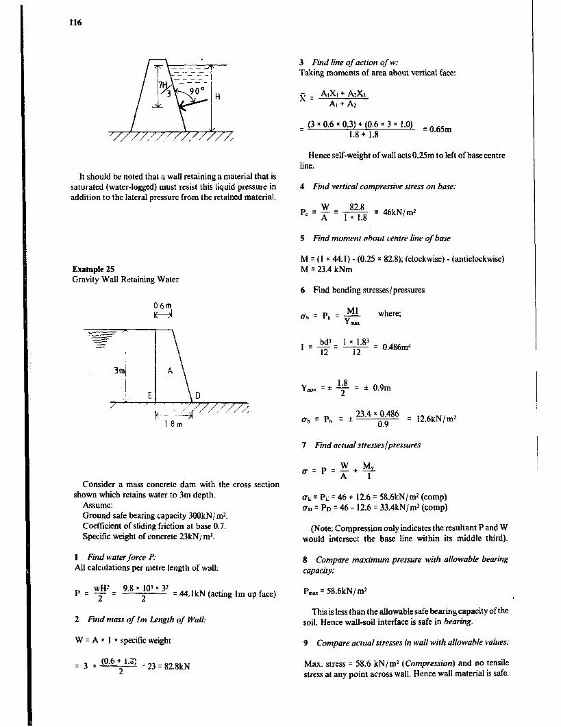
116
It should be noted that a wall retaining a material that is saturated (water-logged) must resist this liquid pressure in addition to the lateral pressure from the retained material.
Example 25 Gravity Wall Retaining Water
06m F-A
Consider a mass concrete dam with the cross section shown which retains water to 3m depth.
Assume: Ground safe bearing capacity 3OOkN/ m*. Coefficient of sliding friction at base 0.7. Specific weight of concrete 23kN/ m3.
1 Find water force P: All calculations per metre length of wall:
9.8 x IO’ x 32 2 = 44.1 kN (acting I m up face)
2 Find mass of Im Length of Wall:
W = A x 1 x specific weight
= 3 x (“*6+i-‘: ,v23=828kN 2
3 Find line of action of w: Taking moments of area about vertical face:
x = AIXI + ArXz AI + A2
q (3x0.6x0.3)+(0.6x3x 1.0) 1.8 + 1.8
= 0.65m
Hence self-weight of wall acts 0.25m to left of base centre line.
4 Find verticai compressive stress on base:
= 46kN/m*
5 Find moment about cenlre line of base
M = (I x 44.1) - (0.25 x 82.8); (clockwise) - (anticlockwise) M = 23.4 kNm
6 Find bending stresses/ pressures
where;
hi3 I=-= *2 . 1 ’ 1.~4~ = o 48f,m4
Y - =f 1.8 r: f 09m 2 *
al, = Pb = f 23.4 x 0.486
0.9 q 12.6kN/ m*
7 Find actual stresses/pressures
UE = PL = 46 + 12.6 = 58.6kN/m* (camp) 00 = Pn = 46 - 12.6 = 33.4kN/ m* (camp)
(Note: Compression only indicates the resultant P and W would intersect the base line within its middle third).
8 Compare maximum pressure with allowable bearing capacity:
P,, = 58.6kN/m*
This is less than the allowable safe bearing capacity of the soil. Hence wall-soil interface is safe in bearing.
9 Compare actual stresses in wall wirh allowable values:
Max. stress q 58.6 kN/ m* (Compression) and no tensile stress at any point across wall. Hence wall material is safe.

Structural Design 117
10 Check overturning:
Overturning moment about D = 44.1 x 1 = 44. IkNm Stabilising moment about D = 82.8 x I. 15 = 95.22kNm
Factor of safety overturning = E = 2.16
Pr = wH = 9.8 x 18 x 3 = 29.4kN/m2 Wall safe in overturning.
This acts vertically over the whole base, thus design base for u.d.1. of 29.4kN/ mz.
Pressure PS also acts laterally on th,e side wall at its bottom edge. This pressure decreases linearly to zero at the water surface.
11 Check sliding ir x 52
Total force on base = PrAa = 29.4 * ---4- = 577.3 kN
(acting at centre of base)
4 P
W \1 Total force on side per metre of perimeter walk
P3H 29.4 x 3 -= 2 2
=44.1kN/mrun(actinglmabovebase)
<- F = /u.W
Pressure Due to Granular Materials Granular materials such as sandy soils, gravelly soils and grain possess the property of internal friction (friction between adjacent grains), but are assumed not to nossess the property of cohesion. If a quantity of such rnateizL 1 in a dry condition is tipped on to a flat surface, it will form a conical heap, the shape maintained by tms internal friction between grains. The angle of the sloping side is known as the angle of repose.
Frictional resistance q PW PW = 0.7 x 82.8 = 58kN Horizontal thrust q P = 44.lkN
Since required factor against sliding is 2, there is a deficiency of (2x44.1)-58=30.2kN.
Additional anchorage against sliding should be provided.
Example 26 Circular Water Tank
Diameter 5m, depth of water 3m Water weighs 9.8 x ltPN/m-t Pressure (P) at depth of 3m
3

118
For a dry material the angle of repose is usually equal to the angle of shearing resistance of the material. This angle of shearing resistance is called the angk of’intemalfriction (8). The angle of friction is the essential property of a granular material on ahich Rankine’s theory is based. This theory enables the lateral pressure to be expressed as a proportion of the vertical pressure, which was shown (above) to depend on specific weight and depth only.
In this case at adepth h, the active lateral presswe is given by:
P=kxwxh where: k = a constant dependent on the materials involved
There exists some friction between the retained material and the wall face, but usually this is disregarded giving a relatively simple relationship for k:
k = 1 -sin 0 1 +sine
where
0 = the angle of friction
(i-sine) pa q (I+sinB)
x wH (N/m*) where:
pa = total force per m of wallface (N)
P. q L!L%W x WH2 (N/m length of wafl) (I+sinB) 2
P. = total force per m of wall face (N)
This gives the approximate horizontal resultant force on a vertical wall face, when retaining material that.is level with the top of the wall. lf the surface of the retained material is sloping up from the wail at an angle equal to its angle of repose, a modification is required.
Example 27 Wall retaining soil
beams
Consider the wall shown retaining loose sandy soil to a depth of 2 metres. Tables provide angle of friction 35“, specific weight 18.6kN/mr. Assuming smooth vertical surface and horizontal soil surface using Rankine’s theory gives:
p = (l-shq +a! (1 TSin9)
p = uc y i!$? kNlrn Ien@, (1 + sin 350) .
P = 10.1 kN/m length of wall
If steel posts are placed at 2.5m centres, each post can be approximated to a vertical cantilever beam 2.5m long carrying a total distributed load of 10.1 x 2.5 = 25.25kN of linear variation from’ xero at the top to a maximum at the base. The steel post and foundation concrete must be capable of resisting the applied load, principally in bending but also in shear.
The timber crossbeams can be analyzed as beams simply supported over a span of 2.5m, each carrying a uniformly distributed load. This load is equal to the product of the face area of the beam and the pressure in the soil at a depth indicated by the centroid of area of the beam face.
P= $%$jj- x wh
if beam face is 0.3m high, h=2.0-0.15= 1.85m p = 0.27 x 18.6 x 1.85 = 9.29 kN/mr
Total u.d.1. on beam = 9.29 r 0.3 x 2.5 = 6.97 kN The maximum bending moment at the centre of the span
can be determined and the beam section checked.
Example 28 Grain Storage Bin (The theory given does not apply to deep bins). A shallow bin can be defined as one having a sidewall height of less than
$ tan (45” + 4). for a square bin of side length S.
Consider a square bin of side length 4m and retaining shelled maize corn to a depth of 2m. Assume 8 = 27’; specific weight is 7.7kN/ mr.
Critical height is:
g tan (450 +:) q $tan(45°+J3.50)=2x 1.63=3.26m
Design as shallow bin since depth of gram is only 2m.
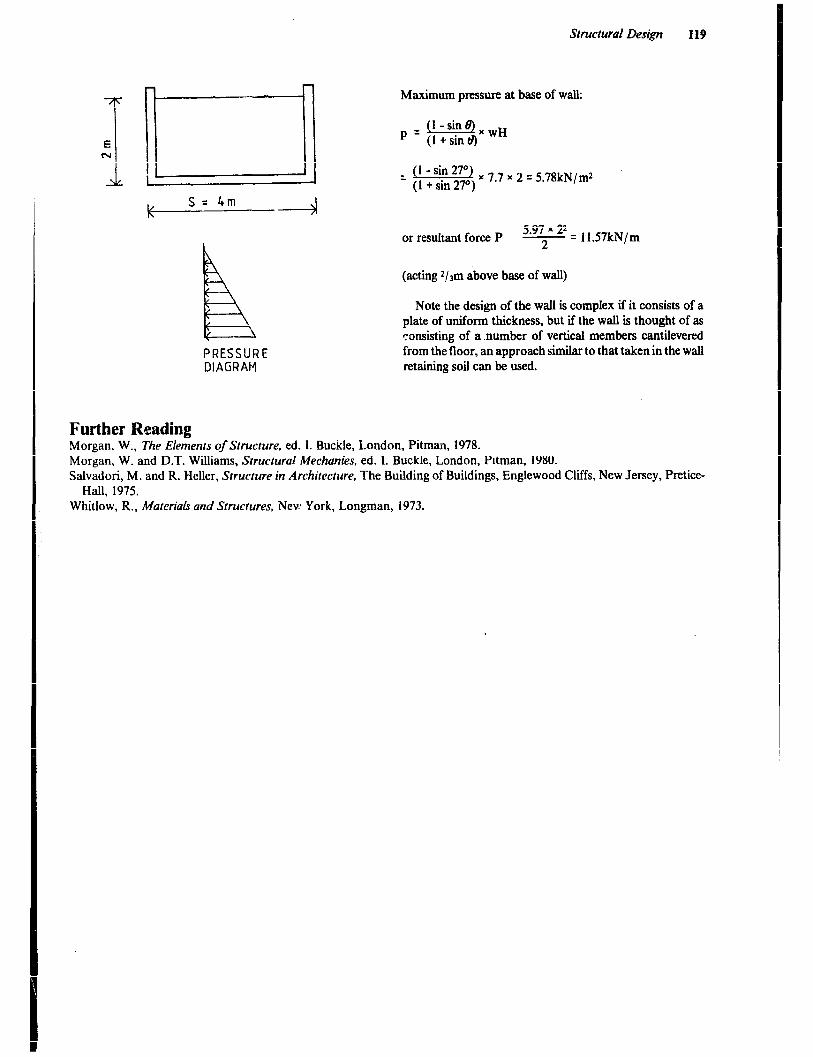
Structural Design 119
Maximum pressure at base of walk
iLz&.!BxwH p = (1 + sin a)
_ (1 -sin 27”) (1 + sin 2,,,) x 7.7 x 2 = 5.78kN/m*
or resultant force P 5.97 x 22 - = 11.57kN/m
2
(acting 2/3m above base of wall)
PRESSURE DIAGRAM
Note the design of the wall is complex if it consists of a plate of uniform thickness, but if the wall is thought of as consisting of a number of vertical members cantilevered from the floor, an approach similar to that taken in the wall retaining soil can be used.
Further Reading Morgan, W., l%he Elements of Structure, ed. 1. Buckle, London, Pitman, 1978. Morgan, W. and D.T. Williams, Srructuruf Mechanics, ed. 1. Buckle, London, Pitman. 1980. Salvadori, M. and R. Heller, Structure in Architecture, The Building of Buildings, Englewood Cliffs, New Jersey, Pretice-
Hall, 1975. Whitlow, R., MuteriaLr and Structures, Nev: York, Longman, 1973.

Chapter 5
Elements of Construction
Elements of Construction ‘When designing a building, an architect plans for spatial, environmental and visual requirements. Once these requirements are satisfied, it is necessary to detail the fabric of the building. The choice of materials and the manner in which they are put together to form building elements such as foundation, walls, floor and roof, depend largely upon their properties relative to environmental requirements and their strength properties. The apprehension of build- ing construction thus involve an understanding of the nature and characteristics of a number of materials, of methods to process them and form them into building units and components, of structural principles, of stability and behaviour under loa& of building production operations and of building economics.
The limited number of materials available in the rural areas of east and south east Africa result in a limited number of structural forms and methods of construction. Different socioeconomic conditions and cultural beliefs are reflected in varying local building !r&itrons. While knowledge of the indigenous building technology is wide- spread, a farmer and his family normally can erect a build- ing using traditional materials and methods without the assistance of skilled or specialized craftsmen. However, population growth and external influences are gradually changing people’s lives and the agricultural practices some traditional materials are getting scarce. Hence, better understanding of traditional materials and methods is needed to allow them to be used more efficiently and effectively. While complete understanding of the indigen- ous technology will enable the architect to design and detail good but cheap buildings, new materials with differing properties may need to be introduced to complement the older and allow for new structural form to develop.
Loads on Building Components Loads are usually divided into the following categories:
Deud loads which result from the ma’ : of all the ele- ments of the building including foot :.gs, foundation, walls, suspended floors, frame and roof. These loads are permanent, fured and relatively easy to calculate.
five loudr which result from the mass of animals, peo- ple, equipment and stored products. Although the mass of these loads can be readily calculated, the fact that the number or amount of components may vary considerably from time to time makes live loads more difficult to esti- mate than dead loads.
Also included as live loads are the forces of nature - wind, earthquake and snow.
Where wind velocities have been recorded, the following equation can be used to determine the expected pressures on building walls:
q = 0,0127 Vzk where:
q q basic velocity pressure, Pa V = wind velocity, ml s k q (h/6.1)2/7 h q design height of building, m
(eave height for low and medium roof pitches) 6.1 = height at which wind velocities were often
recorded for Table 5. I.
While the use of local wind velocity data allows the most accurate calculation of wind pressures on buildings, in the absence of such data, estimates can be made from the Beaufort Scale of Winds given in Table 5.1.
Table 5.1 Beaufort Scale of Windr
Velocity in m, z 6. I m above
ground
Strong breeze Large branches in motion; II - 14 whistling in telephone wires; umbrellas used with diiircdtv.
Moderate gale Whole trees in motion; up to 17 difficult to walk against wind
Fresh gale Twigs break off trees; 21 very difficult to walk against wind
Strong gale Some structural damage to 24 buildings
Whole gale Trees uprooted; considerable 28 structural damage to buildings
Storm Widespread destruction 33
From U.S. Weather Bureau
Some idea of the worst conditions to be expected can be obtained by talking to long-time residents of the area.
The effect of wind pressure on a building is influenced by the shape of the roof and by whether the building is open or completely closed. Table 5.2 gives coefftcients used to determine expected pressures for low-pitch and high-pitch gable roofs and open and closed buildings. Note that there are several negative coefficients indicating that strong anchors and joint fasteners are just as critical as strong structural members.
Data on earthquake forces is very iimited. The best recommendations for areas prone to earthquakes is to use building materials that have better than average tensile characteristics, to design joint fasfeners with an extra fac- tor of safety, and to include a ring beam at the top of the building wall.

Elements of Construction 121
Table 5.2 Wind Pressure Coeficients for Gable Roof Farm Buildings
H:W Windward Wall Windward Roof Coefficient Leeward Roof Leeward Wall Coefficient Roof Slope Coefficient Coefficient
Completely closed 150 30”
1:6:7 0.70 -0.20 0.19 -0.5 -0.4
1:5 0.70 -0.27 0.19 -0.5 -0.4 1:33 0.70 -0.41 0.16 -0.5 -0.4 1.2 0.70 -0.60 0.00 -0*5 -0.4
Open on both sides < 300 300
Windward slope +0.6 +0.8 Leeward slope -0.6 -0.8
H q height to eaves, W q width of building
Table 5.3 Mass of Building Materials
Material kg/m3 kg/ m2
Concrete 2400 Steel 7850 Dense woods 19mm 900 17.0 Soft woods 19mm 580 11.0 Plywood 12mm 7.3 Galvanized roofing 3.9 Concrete hollow lock wall 1OOmm 145
2Xlmm 275 300mm 390
Eij,ick walls 1OOmm 180 200mm 385
Table 5.4 Loa& on Suspended Floors
Cattle Tie stalls Loose housing Young stock ( 180 kg)
Sheep
Horses
Pigs (90 kg) Slatted floor (180 kg) Slatted floor
Poultry Deep litter Cages
Repair shop (allowance) Machinery storage (allowance)
kN/mr
3.4 3.9 2.5
1.5
4.9
2.5 3.2
1.9 Variable
3.5 8
Snow loads are a factor only in very limited areas of high elevation in East and Southeast Africa. Local information on the mass of snow loads should be used.
Table 5.3 provides information useful in determining dead loads and Tables 5.4 and 5.5 give information rele- vant to live loads.
Table 5.5 Mass of Farm Products
Product Angle of repose Mass -.
Emptying FiIling kg/ m3
Maize, shelled Maize, ear Wheat Rice (paddy) Soybeans Dry beans Potatoes Silage Groundnuts, unshelled Hay, loose
baled
27 -
27 36 29 - - -
16 720 - 450 16 770 20 577 16 770 -- 770 37 770 - 480640
218 65-80
190-240
Footings and Foundations A foundation is necessary to support the building and the loads that are within or on the building. The combination of footing and foundation distributes the load on the bear- ing surface and keeps the building level and plumb and reduces settling to a minimum. When properly designed, there should be little or no cracking in the foundation and no water leaks. The footing and foundation should be made of a material that will not fail in the presence 01 ground or surface water. Before the footing for the founda- tion can be designed, it is necessary to determine the total load to be supported.
_ .
If for some reason the load is concentrated in one or more areas, that will need to be taken into consideration. Once the load is determined, the soil bearing characteristics of the site must he studied.
Soil Bearing The topmost layer of soil is seldom suitable for a footing. The soil is likely to be loose, unstable and contain organic material. Consequently, the topsoil should be removed and the footing trench deepened to provide a level, undisturbed surface for the entire buiiding foundation. If this is not

122
feasible because of a sloping site, the footing will need to he stepped. This procedure is described in later and illustrated in Figure 5.5. The footiug should never he placed on a filled area unless there has been sufficient time for consolidation. This usually takes at least one yesr with a normal amount of rainfall. The bearing capacity of soil is related to the soil type and the expected moisture level. Table 5.6 provides typical allowable soil-bearing values.
Table 5.6 Soil Bearing Capacities - Soil Type kN/mZ
Soft, wet, pasty or muddy soil 27 - 35 Alluvial soil, loam, sandy loam (clay +40 to 70% sand) 80- 160
Sandy clay loam (clay +30% sand), moist clay 215 - 270 Compact clay, nearly dry 215 - 270 Solid clay with very line sand - 430 Dry compact clay (thick layer) 320 - 540 Loose sand 160 - 270 Compact sand 215 - 320 Red earth - 320 Mm-ram - 430 Compact gravel 750 - 970 Rock - 1700
An extensive investigation of the soil is not usually necessary for small-scale buildings. Foundation and pier footings can easily be designed to keep within the safe bearing capacity of the soil found on the building site.
Site Drainage It is desirable to site any buiiding on well-drained land. However, other considerations such as access roads, water supply, existing services or a shortage of land may dictate a poorly drained area.
If a building site with poor natural drainage must be used, it may be improved by the use of contour interceptor drains or subsurface drains in order to cut off the flow of surface water or to lower the water-table level. Apart from protecting the building against damage from moisture, drainage will also improve the stability of the ground and lower the humidity of the site. Figures 5.1 and 5.2 illustrate these methods.
Subsurface drains are usually laid 0.6 to 1.5m deep and the pipe layout arranged to follow the slope of the land. The spacing between drains will vary between 10m for clay soils to 50m for sand. Subsurface drains are usually formed from butt-joined clay pipes laid in narrow trenches. In cases where it is desirable to catch water running on the surface, the trench is back-filled nearly to the top with rubble either continuously along the trench or in pockets. A trench filled with rubble or broken stone will provide passage for water and is effective in dealing with flows on the surface. Pipes and trenches belonging to the main site drainage system may cause uneven settling if allowed to
pass close to or under buildings. Where needed a separate drain, that surround the building and installed not deeper than the footing, is used to drain the fcundation trench.
Figure 5.1 Contour interceptor drain.
150 sot1 backfill 150 so11 backfdl
.--~ i_ ji!iJ-
Figure 5.2 Subsurjbce site drains.
Foundation Footings A footing is an enlarged base for a foundation designed to distribute the building load over a larger area of soil and to provide a firm, level surface for constructing the founda- tion wall.
A foundation wall, regardless of the material used for its construction, should be built on a continuous footing of poured concrete. Although the footing will be covered and lean mixes of concrete are considered satisfactory, a foot- ing that is strong enough to resist cracking also helps to keep the foundation from cracking. A 1:3:5 ratio of cement - sand - gravel is suggested with 311 of water per 5Okg sack of cement. The amount of water assumes dry aggregates. If the sand is damp, the water should be reduced by 4 to 51.

Elements of Construction 123
The total area of the footing is determine . by dividing the total load, including an estimated mass for the footing itself, by the bearing by dividing the area by the length. In many cases the widti. equired for light farm buildings will be equal to or less than the foundation walI planned. In that case, a footing that is somewhat wider than the foun- dation is still recommended for at least two reasons. The footings conform .to .small variations in the trench and bridge small areas of loose soil making a good surface on which to begin a foundation wall of any kind. The footings are easily made level and this makes it easier to install the forms for a poured concrete wall or to start the first course of a block or brick wall.
Even when loading does not require it, it is common practice to pour a concrete footing that is as deep as the wall is thick and twice as wide. The foundation footings for large heavy :~G!dings require reinforcing. However, this is seldom necessary for tight-weight farm buildings. Once a firm footing is in place, a number of different materials are suitable for building a foundation. Figure 5.3 shows foot- ing proportions for walls, piers and cohlmns.
Wah Wah and Piers -i, Cdumrts I 1
Figure 5.3 Figure 5.3 Footing &oportions. Footing &oportions. , ,
‘T- $a
Although continuous wall footings are frequently loaded very lightly, that is not the case with column and pier footings. It is important therefore, to carefully esti- mate the proportion of the building load to be carried by each pier or column. Figure 5.4 illustrates the load distribu- tion on a building with a gable roof and a suspended floor.
If walI footings are very lightly loaded, it is advisable to design any pier or column footings required for the build- ing with approximately the same load per unit of area. Then if any settling occurs, it should be uniform through- out. For the same reason, if part of the footing or founda- tion is built on rock, the balance of the footing should be twice as wide as usual for the soil and loading. Footings must be loaded evenly as eccentric loading may cause tipping and failure.
If a foundation is mstalled on a sloping Gte, it may be necessary to dig a stepped trench and install a stepped footing and foundation. It is important that all sections are level and that each horizontal section of the footing is at least twice as long as the vertical drop from the previous section. Reinforcing in the wall as shown in Figure 5.5 is desirable.
Figure 5.4 The division of loadr on footings. ‘Each pier footing must carry I/s of the floor load. The wall must carry 5/s df the floor load and all of the roof and wall load.
I=,-=r= =I
Relnfartlng ]
E===A..
1 H
1
/
V H 3 2v
I I *
Figure 5.5 Steppedfooting andfoundation.
The procedure for finding an appropriate footing may be illustrated using Figure 5.4. Assume a building is 16m long and 8m wide. The roof framing plus the expected wind load totals 130kN. The wall above the foundation is 0.9kN/ m. The floor wffl be used for grain storage and will support as LTuch as 7.3kN/m2. The floor structure is an additional 0.5kN/m2. The foundation wall and piers are each lm high above the footing. The wall is 200mm thick and the piers 300mm square. The soil on the site is judged to be a compact clay in a welldrained area. Find the size of the foundation and pier footing &at will safely support the loads. Assume that the weight of the mass Ikg approxi- mately equals ION. The mass of concrete is 24OOkg/ m3.

124
1 The division of the load on each wall is as follows: a Roof load - 50% on each wall, 13OkN 65kN b Wall load - for each side 16 x 0.9kN 14.4kN c Floor load - each side carries 7/32 x
998kN 218.4kN d Foundation load - each side, 16 x 0.2 x
24kN 76.8kN e Estimated footing - 0.4 x 0.2 x 16 x 24kN 30.7kN
f Total on one side 405.3kN g Force per unit of length 405.3/ 16 25.3kN/ m h Using for practical reasons.
and assumed width of 0.4,25.3/0.4 63.3kN/ rnz i Compact clay at 215 -217kN/ mzeasily carries the load.
2 The division of the load on each pier is: Floor load - !/s x 998kN L24.8 Pier 0.3 x 0.3 * 1 x 24kN 2.2 Footing estimate 0.8 x 0.8 x 0.5 x 24kN 7.7
Total 134.7kN Load/m2 2lOkN/mz
O.K. but 1 x 1 x 0.7 gives more equality to wall loading 144kN/ m2
The most logical action to take would be to add one or more additional piers which would allow both smaller footings and smaller floor support members.
Footing Trenches The trench must be dug deep enough to reach firm, undis- turbed soil. For light buildings in warm climates, this may be as little as 3Ocm. However, for large, heavy buildings footing trenches may need to be up to lm deep.
Pockets of soft material should be dug out and filled with concrete, stones or gravel. The trenches should be free of standing water when the concrete is poured for the footing.
A level trench of the correct depth can be insured by stretching lines between the setting-out profiles (batter boards) and then using a boning rod to check the depth of the trench as it is dug out.
The footing forms should be carefully leveled so that the foundation forms may be easily installed, or a brick or block wall begun. If the foundation walls are to be made of bricks or concrete blocks, it is important that the footings be a whole number of courses below the top of the finished foundation 1eveL
Alternatively the footing can be cast directly in the trench. While this saves the cost of footing forms, care must be taken so that no soil from the sides is mixed in the concrete. Proper thickness for the footing can be ensured by installing guiding pegs, whose tops arc set level and at correct depth, at the center of the foundation trench.
Types of Foundation Foundations may be divided into several categories which are suitable for specific situations.
Corrtinuous wall foundarions may be used either as basement walls or as curtain walls. A continuous wall for a basement of a building must not only support the building but it must be a waterproof barrier capable of resisting the lateral force of the soil on the outside. However, because of the structural problems and the difficulties to exclude water it is recommended to avoid basement constructions in all, but a few special circumstances. Curtain walls are also continuous in nature but being installed in a trench in the soil, they are not usually subjected to appreciable lateral forces and they do not need to be waterproof. Curtain walls may be constructed and then the earth filled back on both sides, or they may be made of concrete poured directly into a narrow trench. Only that portion above ground level requires a form when the concrete is poured. See Figure 5.9. Curtain walls are strong, relatively watertight and give good protection against rodents and other vermin.
Pier foundations are often used to support the umber frames of light buildings with no suspended floors. They require much less excavation and building material. The stone or concrete piers are usually set on footings. However, for very light buildings the pier may take the form of a precast concrete block set on firm soil a few centimeters below ground level. The size of the piers is often given by the weight required to resist wind uplift of the whole building.
Padandpolefoundation consists of small concrete pads poured in the bottom of holes which support pressure treated poles. The poles are long enough to extend and support the roof structure. This is probably the least expensive type of foundation and is very satisfactory for light buildings with no floor loads and where pressure treated poles are available.
A floating slab or raft foundation consists of a poured concrete floor in which the outer edges are thickened to 20 to 3Ocm and reinforced. T’his is a simple system for small buildings that must have a secure joint between the floor and the sidewalls.
A pier and ground level beam foundation is commonly used where extensive filling has been necessary and the foundation would have to be very deep in order to reach undisturbed soil. It consists of a reinforced concrete beam supported on piers. The piers need to be deep enough to reach undisturbed soil and the beam must be embedded in the soil deeply enough to prevent rodents from burrowing under it. For very light buildings such as greenhouses, timber grouad level beams may be used.
Piles are long columns that are driven into ssft ground where they suppoz-t their load by friction with the soil rather than by a film layer at their lower end. They are seldom used for farm buiidings.
Foundation Materials The foundation material should be at least as durable as the balance of the structure. Foundations are subject to attack by moisture, rodents, termites and to a limited extent, wind. The moisture may come from rain, surface
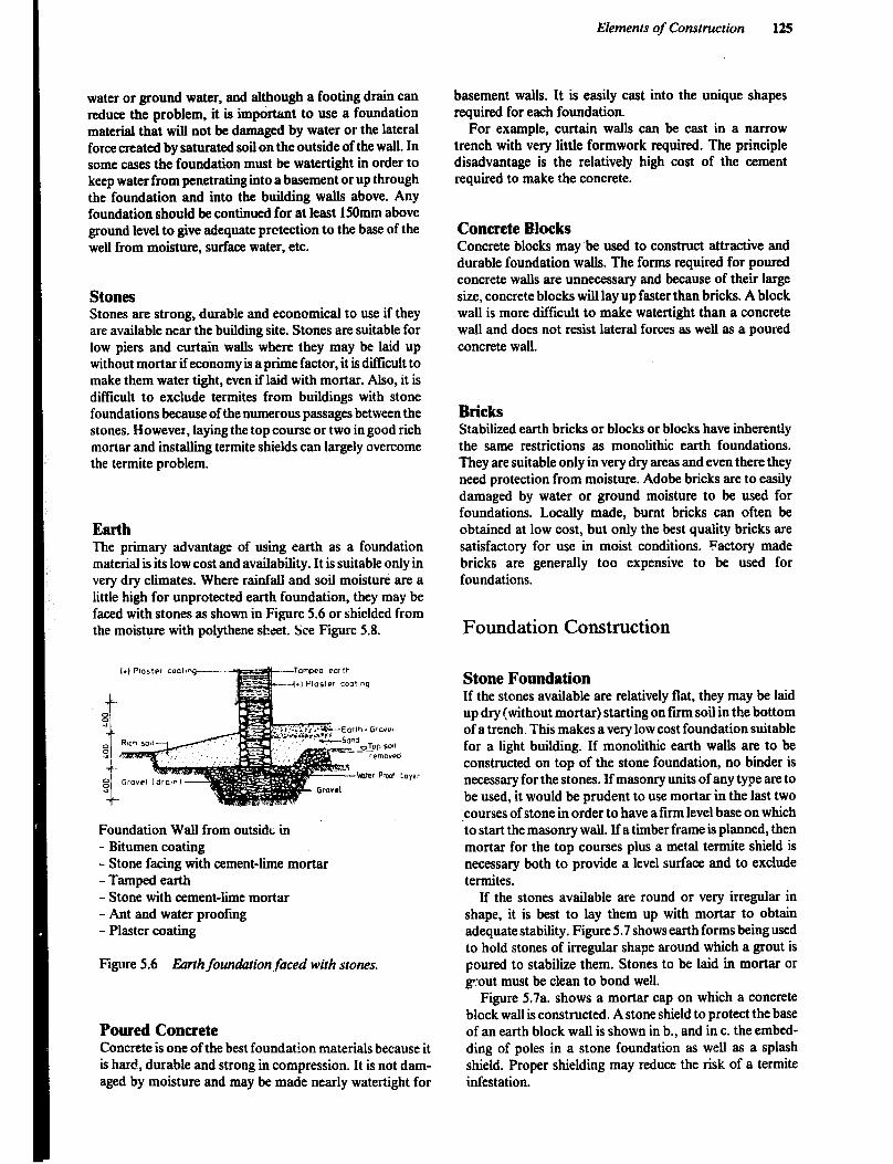
Elements of Construction 125
water or ground water, and although a footing drain can reduce the problem, it is important to use a foundation material that will not be damaged by water or the lateral force created by saturated soil on the outside of the wail. In some cases the foundation must be watertight in order to keep water from penetrating into a basement or up through the foundation and into the building walls above. Any foundation should be continued for at least 150mm above ground level to give adequate prctection to the base of the well from moisture, surface water, etc.
stones Stones are strong, durable and economical to use if they are available near the building site. Stones are suitable for low piers and curtain walls where they may be laid up without mortar if economy is a prime factor, it is diflicult to make them water tight, even if laid with mortar. Also, it is difficult to exclude termites from buildings with stone foundations because of the numerous passages between the stones. However, laying the top course or two in good rich mortar and installing termite shields can largely overcome the termite problem.
Earth The primary advantage of using earth as a foundation material is its low cost and availability. It is suitable only in very dry climates. Where rainfall and soil moisture are a little high for unprotected earth foundation, they may be faced with stones as shown in Figure 5.6 or shielded from the moisture with polythene sheet. SCM Figure 5.8.
Foundation Wall from outsidt in - Bitumen coating - Stone facing with cement-lime mortar - Tamped earth - Stone with cement-lime mortar - Ant and water proofing - Plaster coating
I I Figure 5.6 Ebrrh foundation,faced with stones.
Poured Concrete Concrete is one of the best foundation materials because it is hard, durable and strong in compression. It is not dam- aged by moisture and may be made nearly watertight for
basement walls. It is easily cast into the unique shapes required for each foundation.
For example, curtain walls can be cast in a narrow trench with very little formwork required. The principle disadvantage is the relatively high cost of the cement required to make the concrete.
Concrete Blocks Concrete blocks may be used to construct attractive and durable foundation walls. The forms required for poured concrete walls are unnecessary and because of their large size, concrete blocks will lay up faster than bricks. A block wall is more difficult to make watertight than a concrete wall and does not resist lateral forces as well as a poured concrete wall.
Bricks Stabilized earth bricks or blocks or blocks have inherently the same restrictions as monolithic earth foundations. They are suitable only in very dry areas and even there they need protection from moisture. Adobe bricks are to easily damaged by water or ground moisture to be used for foundations. Locally made, burnt bricks can often be obtained at low cost, but only the best quality bricks are satisfactory for use in moist conditions. Factory made bricks are generally too expensive to be used for foundations.
Foundation Construction
Stone Foundation If the stones available are relatively flat, they may be laid up dry (without mortar) starting on firm soil in the bottom of a trench. This makes a very low cost foundation suitable for a light building. If monolithic earth walls are to be constructed on top of the stone foundation, no binder is necessary for the stones. If masonry units of any type are to be used, it would be prudent to use mortar in the last two courses of stone in order to have a firm level base on which to start the masonry wall. If a timber frame is planned, then mortar for the top courses plus a metal termite shield is necessary both to provide a level surface and to exclude termites.
If the stones available are round or very irregular in shape, it is best to lay them up with mortar to obtain adequate stability. Figure 5.7 shows earth forms being used to hold stones of irregular shape around which a grout is poured to stabilize them. Stones to be laid in mortar or grout must be clean to bond well.
Figure 5.7a. shows a mortar cap on which a concrete block wall is constructed. A stone shield to protect the base of an earth block wall is shown in b., and in c. the embed- ding of poles in a stone foundation as well as a splash shield. Proper shielding may reduce the risk of a termite infestation.
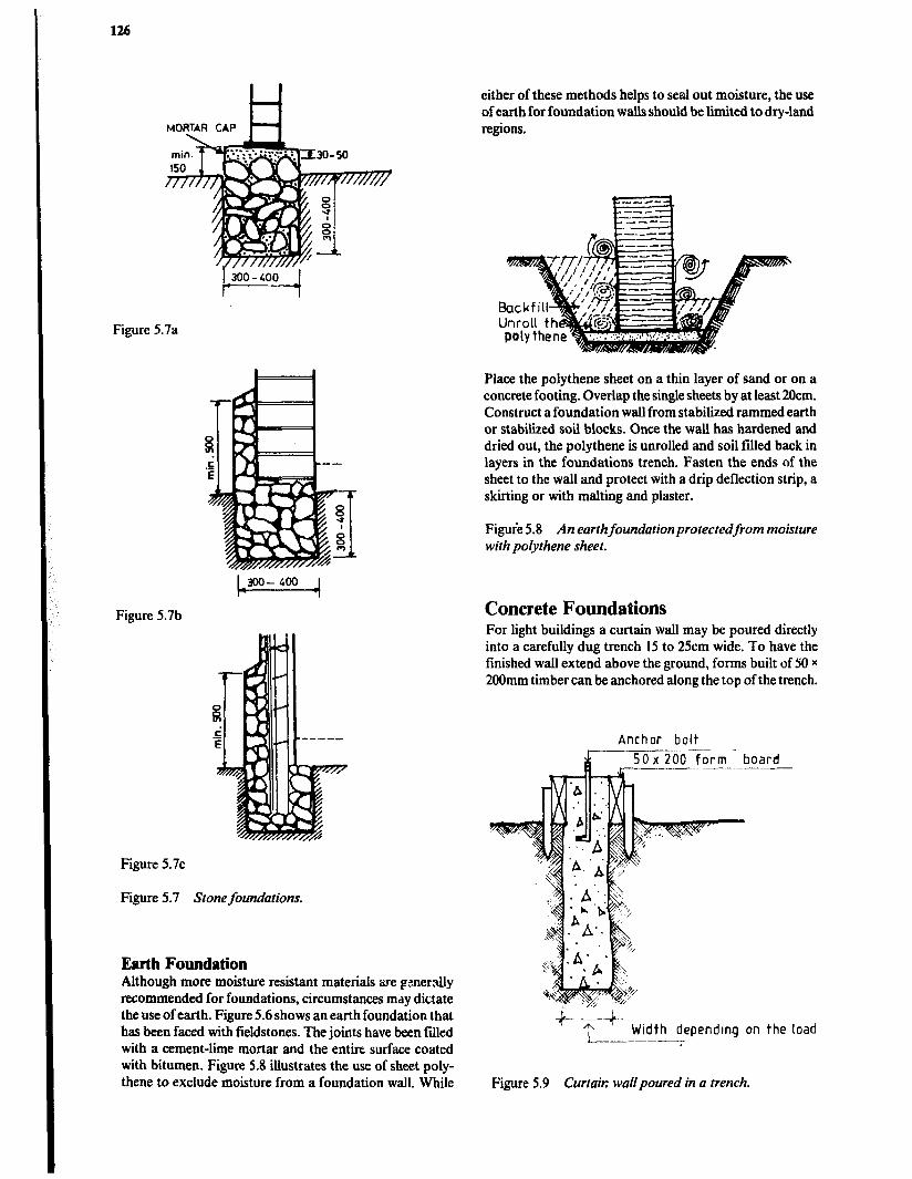
126
MORTAR CAP t=l
Figure 5.7a
Figure 5.7b
Figure 5.7~
Figure 5.7 Stone foundations.
Earth Foundation Although more moisture resistant materials are gmer.ally recommended for foundations, circumstances mdy dictate the use of earth. Figure 5.6 shows an earth foundation that has been faced with fieldstones. The joints have been filled with a cement-lime mortar and the entire surface coated with bitumen. Figure 5.8 illustrates the use of sheet poly- thene to exclude moisture from a foundation wall. While
either of these methods helps to seal out moisture, the use of earth for foundation wails should be liited to dry-land regions.
Place the polythene sheet on a thin layer of sand or on a concrete footing. Overlap the single sheets by at least 2Ocm. Construct a foundation wall from stabilized rammed earth or stabilized soil blocks. Once the waU has hardened and dried out, the polythene is unrolled and soil fffled back in layers in the foundations trench. Fasten the ends of the sheet to the wall and protect with a drip deflection strip, a skirting or with malting and plaster.
Figure 5.8 An earthfoundationprotectedfrom moisture with polythene sheet.
Concrete Foundations For light buildings a curtain wall may be poured directly into a carefully dug trench 15 to 25cm wide. To have the finished wall extend above the ground, forms built of SO x 200mm timber can be anchored along the top of the trench.
Anchor bolt
*-’ Width depending on the load 1
Figure 5.9 Curtair: wallpoured in a trench.

Elements of Construction 121
A relatively lean mix of concrete, 1:4l:8, can be used. T!le concrete must be placed carefully to keep the walls of the trench from sloughing off and mixing in, thereby causing weak spots. If the soil is not stable enough to allow digging a trench form, a wide excavation and the use of simple forms will be required.
Additional information on ratios, materials, forms, plac- ing and curing concrete will be found in Chapter 3.
Concrete Block Foundation It is desirable for all dimensions of a block wall to be divisable by 225mm. this will allow full or half blocks to be used at all corners and openings without the need to cut blocks to odd lengths. Blocks must be dry when used or the mortar joints will not develop full strength.
Concrete block foundations should be started in a full bed of mortar on a poured concrete footing. A 1: 1:5 ratio of cement-lime-sand makes a good mortar. The corner blocks should be carefully located and checked for level- ness and plumb. After several blocks have been laid adja- cent to the comers, a tine stretched between the corners can be used to align the top outside edge of each course of blocks as shown in Figure 5.10. After the first course, face-shell bedding is used. That is, mortar is placed along the vertical edges of one end and the side edges of the top of the block. This will save up to 50% of the mortar and is about threequarters as strong as full bedding.
Mortar to header face
tar applied
f.m edges only
Figure 5.10 Face-shell bonding in blockwall.
Masonry units must be overlapped so that the vertical joints are staggered in order to obtain adequate strength. Where small units such as bricks are used, the bonding must be both along and across the wall. However, blocks are only bonded longitudinally. Cross bonding is required only at points of reinforcement such as pilasters. A half-lap bond is normal, but where necessary to permit bonding at returns and intersecting walls, this may be reduced to one-quarter of the block length, though not less than 65mm.
The strength of blocks of either dense or lightweight aggregate is sufficient for normal small-scale work, but where loading is heavy only dense concrete blocks are y;itable. Hollow blocks may be used for load-bearing
walls, but the courses directly supporting floor and roof structures should be built of solid construction in order to distribute the loading over the length of the wall and thus avoid the concentration of stresses.
The thickness, length and height of the wall determine its structural stability. Table 5.7 indicates suitable relation- ships for free-standing, single-thickness, unreinforced, concrete block walls not externally supported and not tied or fixed at the top and designed to resist wind pressure. Longer and higher walls and, for example, walls retaining bulk grain may need the extra strength of being tied to a pier or crosswall.
Expanded metal or -1 /
wire mesh strips I/c.
Figure 5.11 Reinforcing block walls.
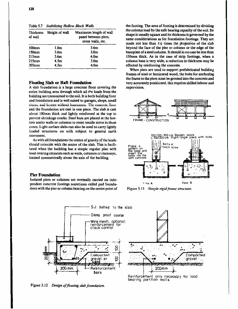
12s
Table 5.7 Stabilting Hollow Block Walk
Thickness Height of wall Maximum length of wall of wall panel between piers,
cross walls, etc.
loomm 1.8m 3.6m 150mm 3.0m 3.0m 215mm 3.6m 4.0m 215mm 4.5m 3.0m 305mm 4.5m 4.0m
Floating Slab or Raft Foundation A slab foundation is a large concrete floor covering the entire building area through which all the loads from the building are transmitted to the soil. It is both building floor and foundation and is well suited to garages, shops, small stores, and homes without basements. The concrete floor and the foundation are cast in one piece. The slab is cast about 1OOmm thick and lightly reinforced at the top to prevent shrinkage cracks. Steel bars are placed at the bot- tom under walls or columns to resist tensile stress in these zones. Light surface slabs can also be used to carry lightly loaded structures on soils subject to general earth movement.
As with all foundations the centre of gravity of the loads should coincide with the centre of the slab. This is facili- tated when the building has a simpie regular plan with load-bearing elements such as walls, columns or chimneys, located symmetrically about the axis of the building.
Pier Foundation Isolated piers or columns are normalIy carried on inde- pendent concrete footings sometimes &led pad founda- tions with the pier or column bearing on the centre point of
the footing. The area of footing is determined by dividing the column load by the safe bearing capacity of the soil. Its shape is usually square and its thickness is governed by the same considerations as for foundation footings. They are made not less than 11% times the projection of the slab beyond the face of the pier or column or the edge of the baseplate of a steel column. It should in no case be less than 150mm thick. As in the case of strip footings, when a column base is very wide, a reduction in thickness may be effected by reinforcing the concrete.
When piers are used to support prefabricated building frames of steel or laminated wood, the bolts for anchoring the frame to the piers must be grouted into the concrete and very accurately positioned. this requires skilled labour and supervision.
lOO/lOO- 150 cm Wooden posts L. 100/200 cm Right- angle piece with bolts
\‘iDW * View B
Figure 5.13 Simple rigidframe structure.
Sill bolted to the slab
? Damp proof course
r Wire mesh, optional reinforcement for crack control
1 bars
5.12 Design offlooting slob foundation. Figure
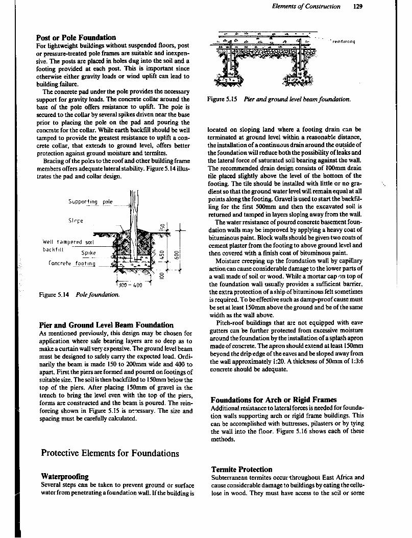
Elements of Construction 129
Post or Pole Foundation For lightweight buildings without suspended floors, post or pressure-treated pole frames are suitable and inexpen- sive, The posts are placed in holes dug into the soil and a footing provided at each post. This is important since otherwise either gravity loads or wind uplift can lead to building failure.
The concrete pad under the pole provides the necessary support for gravity loads. The concrete collar around the base of the pole offers resistance to upliit. The pole is secured to the collar by several spikes driven near the base prior to placing the pole on the pad and pouring the concrete for the collar. While earth backfill should be well tamped to provide the greatest resistance to uplift a con- crete collar, that extends to ground level, offers better protection against ground moisture and termites.
Bracing of the poles to the roof and other building frame members offers adequate lateral stability. Figure 5.14 illus- trates the pad and collar design.
Slope
-luw Well tampered salI
bachflll - Spoke -- -&j
Concrete foottnq ._-&
SupportIng pole
Figure 5.14 Pole founhion.
Pier and Ground Level Beam Foundation As mentioned previously, this design may be chosen for application where safe bearing layers are so deep as to make a curtain wall very expensive. The ground level beam must be designed to safely carry the expected load. Ordi- narily the beam is made 150 to 200mm wide and 400 to apart. Fit the piers are formed and poured on footings of suitable size. The soil is then backfilled to 150mm below the top of the piers. After placing l5Omm of gravel in the trench to bring the level even with the top of the piers, forms are constructed and the beam is poured. The rein- forcing shown in Figure 5.15 is nzessary. The size and spacing must be carefully calculated.
Protective Elements for Founciatians
Waterproofing Several steps can be taken to prevent ground or surface water from penetrating a foundation wall. If the building is
Figure 5.15 Pier and ground level beam foundation.
located on sloping land where a footing drain can be terminated at ground level within a reasonable distance, the installation of a continuous drain around the outside of the foundation will reduce both the possibility of leaks and the lateral force.of saturated soil bearing against the wall. The recommended drain design consists of 1OOmm drain tile placed slightly above the level of the bottom of the footing. The tile should be installed with little or no gra- dient so that the ground water level will remain equal at all points along the footing. Gravel is used to start the backfiI- ling for the first 5OOmm and then the excavated soil is returned and tamped in layers sloping away from the wall.
The water resistance of poured concrete basement foun- dation walls may be improved by applying a heavy coat of bituminous paint. Block walls should be given two coats of cement plaster from the footing to above ground level and then covered with a finish coat of bituminous paint.
Moisture creeping up the foundation wall by capillary action can cause considerable damage to the lower parts of a wall made of soil or wood. While a mortar cap on top of the foundation wall usually provides a sufficient barrier, the extra protection of a ship of bituminous felt sometimes is required. To be effective such as damp-proof cause must be set at least 150mm above the ground and be of the same width as the wall above.
Pitch-roof buildings that are not equipped with cave gutters can be further protected from excessive moisture around the foundation by the installation of a splash apron made of concrete. The apron should extend at least 150mm beyond the drip edge of the eaves and be sloped away from the wall approximately 1:20. A thickness of 50mm of 1:3:6 concrete should be adequate.
Foundations for Arch or Rigid Frames Additional resistance to lateral forces is needed for founda- tion walls supporting arch or rigid frame buildings. This can be accomplished with buttresses, pilasters or by tying the wall into the floor. Figure 5.16 shows each of these methods.
Termite Protection Subterranean termites occurthroughout East Africa and cause considerable damage to buildings by eating the cellu- lose in wood. They must have access to the scil or some

130
Buttress
Pilaster
other constant source of water. They can severely damage timber in contact with the ground and may extend their attack to the roof timbers of high buildings. Entrance to unprotected structures is gained through cracks in concrete or masonry walls, through the wood portion of the house or by building shelter tubes over foundation posts and Walls.
The main objective in termite control is to break the contact between the termite colony in the ground and the wood in the building. This can be done by blocking the passage of the termites from soil to wood, by constructing a slab floor under the entire building, and/or installing ter- mite shields, treating the soil near the foundation and under concrete slabs with suitable chemicals, or by a com- bination of these methods.
Creepers, climbers and other vegetation likely to provide means of access for termites should not be permitted to grow on or near a building.
Chemical protection is useful if termite shields are not available, but is also recommended in combination with mechanical protection. Creosote oil, sodium arsenite, pen- tachlorophenol, pentachlorophenol, pentachlorphenate, copper napthenate, benzene hexachloride and dieldrin are the products predominantly used. The protective duration is 4 to 9 years depending on soil and weather conditions. Timber elements are impregnated before use. The timber surface is protected only if sprayed with insecticide prior to painting. Cracks, joints and cut surfaces must be protected with special care as termite attacks always start in such locations.
Slab on the ground construction: Firstly, the construc- tion site must be carefully cleaned and all termite colonies be traced down, broken and poisoned with 50 to 2001 chemical emulsion. Secondly, after the top soil has been removed and any excavation is completed, poison should be applied at a rage of S/m2 over the entire area to be covered by the building. The soil used as backfill along the inside and outside of the foundation, around plumbing and in the wall voids is treated at a rate of 61/ m run and before casting the floor slab any hardcore fill and blinding sand should also be treated. Existing buildings can be given some protection by digging a 30cm wide and 15 to 3Ocm deep trench around the outside of the foundation. After having sprayed the trench with poison, the excavated soil is treated and replaced.
It is advisable to do the soil poisoning when the soil is fairly dry and when rain is not pending, otherwise there is risk of the chemical being washed away instead of being absorbed by the soil.
It is also advisable to cover the poisoned band of soil with concrete or with a substantial layer of gravel. This protects the poison barrier and helps to keep the wall clean and free of mud splashes. If the wall is rendered, it is preferable to poison any rendering that is applied within 3Ocm or so of the ground. To poison concrete or sand:ce- ment mortar, simply use a 0.5 to 1.0% dieldrin emulsion instead of the usual mixing water. There is no effect on the
Floortie amount of water required or the binding strength of the cement.
Figure 5.16 Metho& of strengthening foundations. All preservatives are toxic and should be handled with
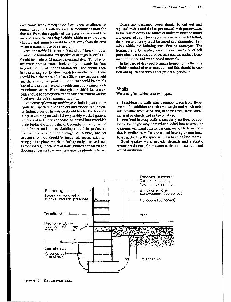
care. Some are extremely toxic if swallowed or allowed to remain in contact with the skin. A recommendation for first-aid from the supplier of the preservative should be insisted upon. When using dieldrin, aldrin or chlorodane, children and animals should be kept away from the area where treatment is to be carried out.
Termite s!Gefds: The termite shield should be continuous around the foundation irrespective of changes in level and should be made of 24 gauge galvanized steel. The edge of the shield should extend horizontally outwards for 5cm beyond the top of the foundation wall and should then bend at an angle of 45O downwards for another 5cm. There should be a clearance of at least 20cm between the shield and the ground. All joints in the shield should be double locked and properly sealed by soldering or brazing or with bituminous sealer. Holes through the shield for anchor bolts should be coated with bituminous sealer and a washer fitted over the bolt to ensure a tight fit.
Protection of existing buildings: A building should be regularly inspected inside and out and especially at poten- tial hiding places. The outside should be checked for such things as staining on walls below possibly blocked gutters, accretion of soil, debris or added-on items like steps which might bridge the termite shield. Ground-floor window and door frames and timber cladding should be probed to dtssqver decav or ter-mkc :! smage. All timber, whether structural or not, should be inspected. special attention being paid to places which are infrequently observed such as roof spaces, under-sides of stairs, built-in cupboards and flooring under sinks where there may be plumbing leaks.
Elements of Construction 131
Extensively damaged wood should be cut out and replaced with sound timber pre-treated with preservative. In the case of decay the source of moisture must be found and corrected and where subterranean termites are found, their source of entry must be traced and eliminated. Ter- mites within the building must first be destroyed. T’he treatments to be applied include some measure of soil poisoning, the provision of barriers and the surface tmat- ment of timber and wood-based materials.
In the case of drywood termites fumigation is the only reliable method of extermination and this should be car- ried out by trained men under proper supervision.
Walls Walls may be divided into two types:
a Load-bearing walls which support loads from floors and roof in addition to their own weight and which resist side pressure from wind and, in some cases, from stored material or objects within the building, b non-load-bearing walls which carry no floor or roof loads. Each type may be further divided into external or eaclosing walls, and internal dividing walls. The term parti- tion is applied to walls, either load-bearing or non-load- bearing, dividing the space within a building into rooms.
Good quality walls provide strength and stability, weather resistance, fire resistance, thermal insulation and sound insulation.
Poisoned relnforced
Rendering-------
Lower courses Lower courses so11 50110 blocks, mortar blocks, mortar po polsoned -4
Ter mitt Termite shield-
Concrete capping 10cm thick minimum
-B inding sand or sand-cement (poisoned 1
ardcore (poisoned)
Clearance 20cm
Figure 5.17 Termite protection.

132
Types of Building Walls Theie are various way< to construct a wall and many different materials can be used, but they can be divided into four main groups.
Masonry wall, in which the wall is built of individual blocks of materials such as brick, clay or concrete blocks, or stone, usually in horizontal courses bonded together with some form of mortar. Several of the earth derived products, either air dried or ftred, are reasonable in cost and weIl suited to the climate.
Monolithic walI, in which the wall is built of a material placed in forms during the construction. The traditional earth wall and the modem concrete wall are examples. The earth walls are inexpensive and durable if placed on a good foundation and protected from rain by a rendering or wide roof overhangs.
Frame wall, in which the wall is constructed as a frame of relatively small members, usually of timber, at close inter- vals which together with facing or sheething on one or both sides form a load-bearing system. Offcuts are a low-cost material to use for a frame wall covering.
Membrane wall, in which the wall is constructed as a sandwich of two thin skins or sheets of reinforced plastic, metal, asbestos-cement or other suitable material bonded to a core of foamed plastic to produce a thin wall element of high strength and low weight.
Another form of construction adapted for framed or earth buildings consists of ielatively light sheeting secured to the face of the wall to form the enclosed element. These are generaLly termed ‘claddings’.
Factors which will determine the type of wall to be used are: a The materials available at a reasonable cost. b Availability of craftsmen capable of using the materials in the best way. c Climate d The use of the building - functional requirements.
The height of walls should allow people to walk freely and work in a room without knocking their heads on the ceiling, beams etc. In dwelling houses with ceilings is 2.4m a suitable height. Low roofs or ceilings in a house create a depressing atmosphere and tend to make the rooms warmer in hot weather.
Masonry Walls Apart from certain forms of stone walling, all masonr: consists of rectangular units built up in horizontal layers called courses. The units are laid up with mortar in specitic patterns called bonding in order to spread the loads and resist overturning and in the case of thicker walls, buckling.
The material in the masonry units can be mud or adobe bricks, burnt clay bricks, soil blocks (stabilized or unstabil- ized), concrete blocks, stone blocks or rubble. Blocks can be solid or hollow.
Spread of load in bonded wall
lateral pressure.
Restriction of over turning by bonding
Figure 5.18 Ejramplesshowing why bonding ik necessary.
Units laid across wall in alternate .
Bond:ng ot walls built with narrow joints

Elements of Construction
odd courser
ENGLISH BOND FLEMHISH BOND
Figure 5.19 English and Flemish bonding of brick walls.
Bricks In brickwork, those bricks laid lengthwise in the wall are called stretchers and the course in which they occur, a stretching course. Bricks laid across the wall thickness are called headers and the course in which they occur, a heud- ing course.
Bricks may be arranged in a wide variety of ways to produce a satisfactory bond and each arrangement is iden- tified by the pattern of headers and stretchers on the face of the wall. These patterns vary in appearance resulting in characteristic ‘texturcs’in the wall surfaces, and a particu- lar bond may be used for its surface pattern rather than for its strength properties. In order to maintain bond it is necessary at some points to use bricks cut in various ways, each of which has a technical name according to the way it is cut.
The simplest arrangements, or ‘bonds’as they are called, are stretching bond and heading bond. In the former, each course consists entirely of stretchers laid as in Figure 5.20 and is only suitable for half-brick walls such as partitions, facing for block walls and the leaves of cavity walls. Thicker walls built entirely with stretchers are likely to buckle as shown in Figure 5.18. The heading bond is ordinarily used only for curved walls.
The two bonds most commonly used for walls one brick and over in thickness are known as English bond and Flemish bond. A‘one-brick thickness’is equal to the length of the brick. These bonds incorporate both headers and stretchers in the wall which are arranged with a header placed centrally over each stretcher in the course below in order to achieve a bond and minimize straight joints. In both bonds 120 bricks of standard size are required per mz of 23cm wall. Thii figure allows for 15 to 20% breakage and lcm mortar joints. Figure 5.19 illustrates English and Flemish bonding.
Bricks are sometimes used in the construction of cavity walls since the airspace improves the thermal resistance and the resistance to ram penetration compared to a solid wall of the same thickness. Such a wall is usually built up with an inner and outer leaf in a stretching bond, leaving a space or cavity of 50 to 90mm between the leaves. The two leaves are co~ected by metal wag ties spaced 900mm horizontally and 450mm vertically as shown in Figure 5.20.
Figure 5.20 Brick cavity wall.
Concrete Blocks Much of the procedure for the construction of concrete block walls has been discussed under the heading’Founda- tions’. However, there are a few additional factors to bc considered.
It is best to work with dry, well-cured blocks to reduce shrinking and cracking in the wall to a minimum. Except at quoins (comers), load-bearing concrete block walls should not be bonded at junctions as in brick and stone masonry. At junctions one wall should butt against the face of the other to form a vertical joint which allows for movement in the walls and thus controls cracking. Where lateral support must be provided by an intersecting wall, the two can be tied together by 5mm x 30mm metal ties with split ends, spaced vertically at intervals of about 12OOmm. Expansion joints should be allowed at intervals not exceeding 2!4 times the wall height. The two sections of wall must be keyed together or stabilized bypverlapping jamb blocks as shown in Figure 5.21. The joints are sealed with flexible mastic to keep water from penetrating the wall.

134
Figure 5.21 Loteralsupportfor walLrat expansion joints.
Many walls in the tropics are required to let in light and air while acting as sun-breakers. To meet this need, perfo- rated walls are popular and are designed in a variety of patterns, some load bearing, others of light construction. Hollow concrete blocks may be **ed to good effect for this purpose. Horizontal or vertical slabs of reinforced concrete (r.c. slots) can be used to act as sun-breakers. These are usually built at an inclined angle in order to obtain maxi- mum shelter from the sun.
Stones Quarried stone blocks, either rough or dressed to a smooth surface are laid in the same way as concrete or stabilized soil blocks. Random rubble walls are built using stones of random size and shape as they are found or come from the quarry. Walls using iaminatcd varieties of stone which split easily to reasonably straight faces of random size are called squared rubble walling.
In these walls, as in all masonry, longitudinal bond is achieved by overlapping stones in adjacent courses, but the amount of overlap varies because the stones vary in size. Since rubble walls are essentially built as two skins with the irregular space between solidly tilled with rubble material (small stones), transverse bond or tie is ensured by the use of long header stones known as bonders. These extend not more than threequarters through the wall thickness to avoid the passage of moisture to the inner face of the wall and at least one is required for each m2 of walI face. Large stones, reasonably square in shape or roughly squared, are used for corners and !?e jambs of door and window open- ings to obtain increased strength and stability at these points.
Random rubble walls may be built as uncoursed walling in which no attempt is made to line the stones into horizon- tal courses, or it may be brought to courses in which the stones are roughly IevelIed at 3OOmm to 450mm intervals to form courses varying in depth with the quoin and jamb stones.
Rough squaring of the stones has the effect of increasing the stability of the wall and improving its weather resist- ance since the stones bed together more closely, the joints are thinner, and therefore there is less shrinkage in the joint mortar. External load-bearing stone walls should he at least 300mm thick for one-story F :;ldings.
Openings in Masonry Walls Openings in masonry walls are required for doors and windows. The width of opening, height of the wall above the opening and strength of the wall on bither side of the opening are major design factors. They are particularly important where there are many openings that are quite close together in a wall.
The support over an opening may be a lintel of wood, steel or reinforced concrete or it may be an arch con- structed of masonry units similar to or the same as used in the adjoining wall. Lintels impose only vertical loads on the adjoining sections of walls and are themselves subjected to bending and shear loads and compression loads at their support points. Concrete lintels may either be cast in place or prefabricated and installed as the wall is constructed.
PIERCED BLOCK WCLLlNG PIERCE BLOCKWALL VENTlL4TICN OPENING
mode ot hollow blocks us,ng decorative concrete blocks
Figure 5.22 Block walls for ventilation.
PLAN
vertical PC slats 300x 6Omn
upto 30m high
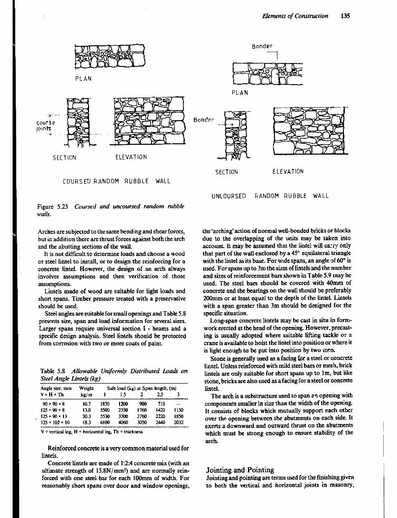
Elements of Construction 135
-“- --
cour4.e jointq
*
Bonder
---I
PLAN
PLAN
SECTION ELEVATION
Bonder
SECTION ELEVATION
COURSED RANDOM RUBBLE WALL
UNCOURSED GANOOM RUBBLE WALL
Figure 5.23 Coursed and uncoursed random rubble walls.
Arches are subjected to the same bending and shear forces, but in addition there are thrust forces against both the arch and the abutting sections of the wail.
It is not difficult to determine loads and choose a wood or steel lintel to install, or to design the reinforcing for a concrete lintel. However, the design of an arch always involves assumptions and then verification of those assumptions.
Lintels made of wood are suitable for light loads and short spans. Timber pressure treated with a preservative should be used.
Steel angles are suitable for small openings and Table 5.8 presents size, span and load information for several sizes. Larger spans require universal section I - beams and a specific design analysis. Steel lintels should be protected from corrosion with two or more coats of paint.
Table 5.8 Allowable VnQiormlvv Distributed L.oah on Steel Anale L.inteLs (ka)
Angle Size, mm Weight Safe load (kg) at Span length, (m) VnH*Th knlm I 1.5 2 2.5 3
90x90~8 10.7 1830 1200 900 710 -- 125r9Ox8 13.0 3500 2350 1760 1420 1150 125~90~13 20.3 5530 3700 2760 2220 1850 ~ 125 x 102 x 10 18.3 6100 4013 3050 2440 2032
V = vertical leg, H = horizontal leg, Th = thickness
Reinforced concrete is a very common material used for lintels.
Concrete lintels arc made of 1:2:4 concrete mix (with an ultimate strength of 13.8N/ mmz) and are normally rein- forced with one steel bar for each 1OOmm of width. For reasonably short spans over door and window openings,
the ‘arching’action of normal well-bonded bricks or blocks due to the overlapping of the units may be taken into account. It may be assumed that the lintel will ca’,~ only that part of the wall enclosed by a 45” equilateral triangle with the lintel as its base. For wide spans, an angle of 60” is used. For spans up to 3m the sizes of lintels and the number and sizes of reinforcement bars shown in Table 5.9 may be used. The steel bars should be covered with 40mm of concrete and the bearings on the wall should be preferably 200mm or at least equa! to the depth of the lintel. Lintels with a span greater than 3m should be designed for the specific situation.
Long-span concrete lintels may be cast in situ in form- work erected at the head of the opening. However, precast- ing is usually adopted where suitable lifting tackle or a crane is available to hoist the lintel into position or where it is light enough to be put into position by two men.
Stone is generally used as a facing for a steel or concrete lintel. Unless reinforced with mild steel bars or mesh, brick lintels are only suitable for short spans up to lm, but like stone, bricks are also used as a facing for a steel or concrete lintel.
The arch is a substructure used to span ~9 opening with camponents smaller in size than the width of the opening. It consists of blocks which mutually support each other over the opening between the abutments on each side. It exerts a downward and outward thrust on the abutments which must be strong enough to ensure stability of the arch.
Jointing and Pointing Jointing and pointing arc terms used for the finishing given to both the vertical and horizontal joints in masonry,

136
Table 5.9 Reinforced Concrete Lintels.
Lintels with Wall Load Only
Size of Lintel Clear Span Bottom Reinforcement
(mr;i) m Number of Size oi bars bars
H W
150 200 C2.0 2 200 200 2.0 - 2.5 2 200 200 2.5 - 3.0 2
1Dmm. round, deformed lOnun, round, deformed 16mm. round. deformed
150 200 200 200 200 200
Safe bearing at each end, 2OOmm
Split Lintels with Wall Load Only
a.0 1 each 2.0 - 2.5 1 each 2.5 - 3.0 1 each
lOmm, round, deformed lOmm, round, deformed 16mm, round, deformed
‘Arrhmg’ action reduter load
Of wall an IIntel
Figure 5.24a Rough arch
Figure 5.24 openings in masonry walk
Figure 5.24b Opt&g spanner by a reinforced concrete lintel
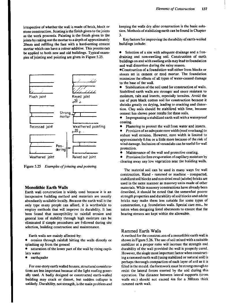
Elements of Construction 137
irrespective of whether the wall is made of brick, block or stone construction. Jointing is the finish given to the joints as the work proceeds. Painting is the finish given to the joints by raking out the mortar to a depth of approximately 20mm and refilling the face with a hard-setting cement mortar which can have a colour additive. This process can be applied to both new and old buildings. Typical exam- ples of jointing and pointing are given in Figure 5.25.
Flush joint Keyed joint
-P c
Recessed joint Weathered pointing
Weathered joint
Figure 5.25 Exa.mples of jointing and pointing.
Monolithic Earth Walls Earth wall construction is widely used because it is an inexpensive building method and materials are usually abundantly available locally. Because the earth wall is the only type m.my people can afford. it is worthwhile to employ methods that will improve its durability. It has been found that susceptibility to rainfall erosion and general loss of stability through high moisture can be eliminated if simple procedures are followed during site selection, building construction and maintenance.
Earth walls are mainly affected by: l erosion through rainfall hitting the walls directly or splashing up from the ground l saturation of the lower part of the wall by rising capil- lary water l earthquake
For one-story earth walled houses, structural considera- tions are less important because of the light roofing gener- ally used. A badly designed or constructed earth-walled building may crack or distort, but sudden collapse is unlikely. Durability, not strength, is the main problem and
keeping the walls dry after construction is the basic solu- tion. Methods of stabilizing earth can be found in Chapter 3.
Key factors for improving the durability of earth-walled buildings include:
0 Selection of a site with adequate drainage and a free- draining and non-swelling soil. Construction of earth buildings on and with swelling so& may lead to foundation and wall distortion during the rainy season. *Construction of a foundation wall either from blocks or stones set in cement or mud mortar. The foundation minimizes the effects of all types of water-caused damage to the base of the wall. 0 Stabilization of the soil used for construction of walls. Stabilized earth walls ,are stronger and more resistant to moisture, rain and insects, especially termites. Avoid the use of pure black cotton soil for construction because it shrinks greatly on drying, leading to cracking and distor- tion. Clay soils should be stabilized with lime, because cement has shown poor results for these soils. l Impregnating a stabilized earth wall with a waterproof coating. l Plastering to protect the wall from water and insects. l Provision of an adequate eave width (roof overhang) to reduce wall erosion. However, eave width is limited to approximately 0.6m or a little more because of the risk of wind damage. Inclusion of verandahs can be useful for wall protection. l Maintenance of the wall and protective coating. l Provision for free evaporation of capillary moisture by clearing away any low vegetation near the building walls.
The material soil can be used in many ways for wall construction. Hand - rammed or machine - compacted, stabilized soil blocks and sun-dried mud (adobe) bricks are used in the same mannor as masonry units made of other materials. While masonry constructions have already been described, it should be noted that the somewhat poorer strength properties and durability of soil blocks and adobe bricks may make them less suitable for some types of construction, e.g. foundation walls. Special care mu,. be taken when designing lintel abutments to ensure that the bearing stresses are kept within the aliowable.
Rammed Earth Walls A method for the construc,lon of a monolithic earth wall is shown in Figure 5.26. The use of soil mixed with a suitable stabilizer at a proper ratio will increase the strength and durability of the wall provided the wall is properly cured. However, the single most important factor when construct- ing a rammed earth wall (using stabilized or natural soil) is perhaps thorough compaction of each layer of soil as it is filled in the mould. the formwork must be strong enough to resist the lateral forces exerted by the soil during this operation. The distance between lateral supports (cross walls etc.) should not exceed 4m for a 300mm thick rammed earth wall.
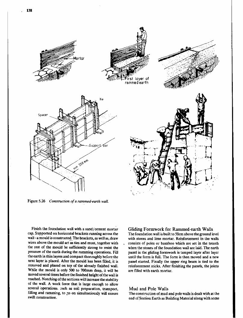
. 138
II..
rammedearth
Figure 5.26 Construction of a rammed-earth wall.
Finish the foundation wall with a sand/cement mot-&r cap. Supported on horizontal brackets running across the wall -a mould is constructed. The brackets, as well as, draw wires above the mould act-as ties and must, together with the rest of the moutd be sufficiently strong to resist the pressure of the earth during the ramming operations. Fill the earth in thin layers and compact thoroughly before the next layer is placed. After the mould has been ftied, it is removed and placed on top of the already finished wall. While the mould is only 500 to 700mm deep, it will be moved several times before the finished height of the wall is reached. Notching of the sections will increase the stability of the wall. A work force that is large enough to allow several operations. f&g and
zuch as soil preparation, transport, rammin g, to go on simultaniously will ensure
swift construction.
.
Gliding Formwork for Rammedearth Walls The foundation wall is built to 5Ocm above the ground level with stones and lime mortar. Reinforcement in the walls consists of poles or bamboo which are set in the trench when the stones of the foundation wall are laid. The earth panel in the gliding formwork is tamped layer after layer until the form is full. The form is then moved and a new panel started. Finally the upper ring beam is tied to the reinforcement sticks. After finishing the panels, the joints are filled with earth mortar.
Mud and Pole Walls The construction of mud and pole walls is dealt with at the end of Section Earth as Building Material along with some

Elements of Construction 139
Figure 5.27 Consrrucrion of a rammed-earth wall with a gliding form.
other types of mud wall constructions. A pole frame wall can be built with either thick earth construction (25cm or more) or thin earth cladding (1Ocm or less). While soil block walls and rammed earth walls usually are superior to mud and pole wall, this should only bc used when a supply of durable poles is available and the soil is not suitable for block making. Regardless of the type of wall, the basis of all improvement is to keep the wall dry titer construction.
Install a dampproof course on top of the foundation wall, about 50cm above ground level. Pre-fabricate ladders out of green bamboo or wooden poles that are about 5cm diameter. The outside wooden or split bamboo battens are nailed or tied to the ladders as the soil is filled in successive layers. The comers must be braced diagonally. Earth- quack resistance is improved by securing the base frame to the foundation with a layer of lime or cement soil mortar.
Framed Walls Frame walls consist of vertical timber members called studs framed between horizontal members at the top and
Figure 5.28 Consrruction of a mud andpole wall.
PLAN .-
bottom. The top member is called a plate and the bottom member a sole or sill. Simple butt joints are used which are end-nailed or toe-nailed. The frame is, therefore, not very rigid and requires bracing in order to provide adequate stiffness.
Diagonal braces can be used for this purpose, but a common method which is quicker and cheaper, is to use building board or plywood sheething to stiffen the struc- ture. The studs are commonly spaced on 400 or 6OOmm centres which is related to the standard 1200mm width of many types of building boards used for sheething. Since the load-bearing members of this type of wall are wood, it is not recommended for termite areas, especially if both faces of the frame are finished or covered, thus making it difficult to detect a termite attack.
Frame construction using timber must be raised out of contact with ground moisture and protected from termites. This is accomplished by erecting it on a base wall or foundation beam rising to a damp-proof course, or on the edge of a concrete slab floor. As a base for the whole structure a siU is set and carefully levelled on the damp- proof course and securely anchored to the foundation. To maintain the effectiveness of the damp-proof course it must be sealed carefully at all bo!i positions. A continuous ter- mite shield should be inatalled between the damp-proof course and the sill md great care taken to seal around the holes required for the anchor bolts. The sill plate may be 1OOmm by 50mm when fared to a concrete base, but should be increased in width to 150mm on a brick base wall.
Instead of timber, bamboo or round wooden poles can be used as studs which are then clad with bamboo mats, reed mats, grass, palm leaves etc. A further alternative is to fix mats to the studs and then plaster the mats with ;cement plaster or other material. Some structures of this type have a short life due to damage by fungi and termites. They are also difficult to keep clean’and the risk of fire is great. Figure 5.30 gives brief information on bamboo wall panels which can be made by skilled craftsmen.
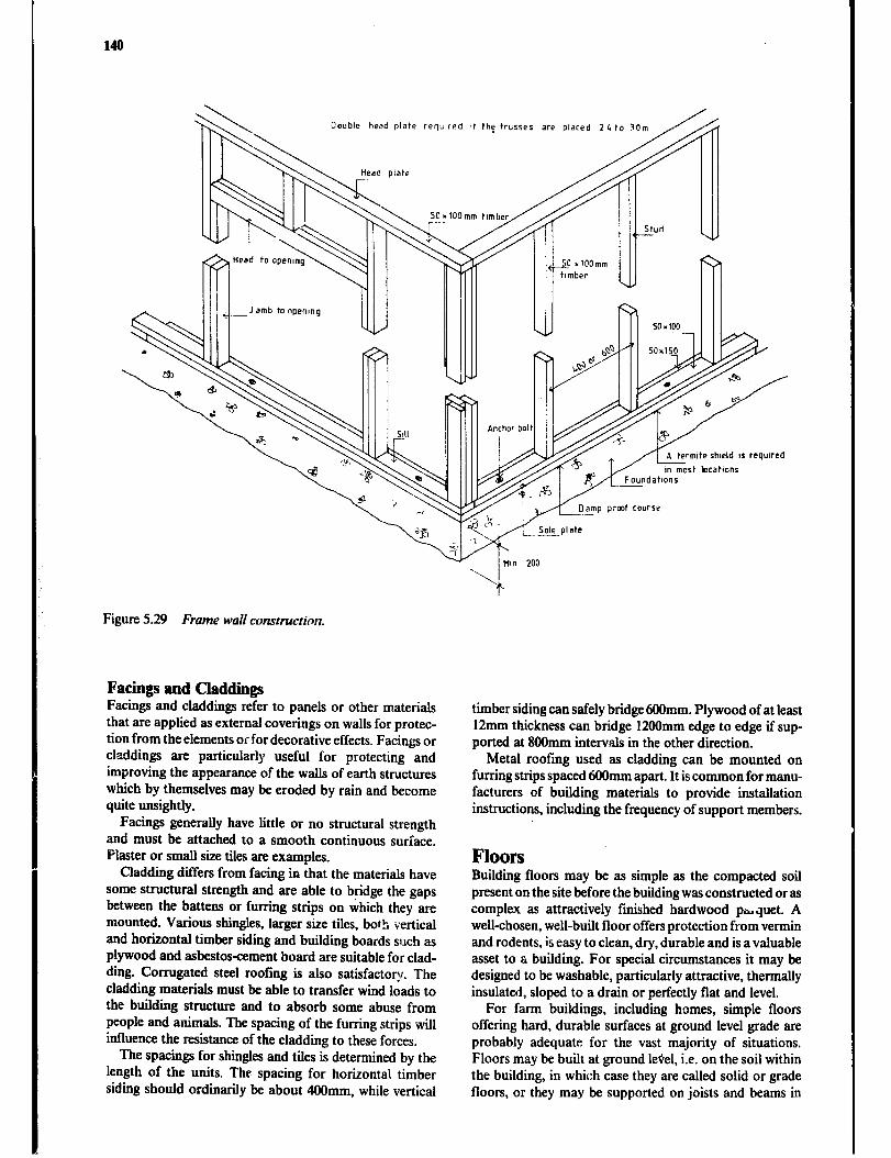
140
Double head plate reqwred at the trusses are placed 2 4 to !Om
rmtte shmld 1s requred
m most iwcatlons
amp prmt course
Figure 5.29 Frame wall construction.
Facings and Claddings Facings and claddings refer to panels or other materials that are applied as external coverings on walls for protec- tion from the elements or for decorative effects. Facings or claddings are particularly useful for protecting and improving the appearance of the walls of earth structures which by themselves may be eroded by rain and become quite unsightly.
Facings generally have little or no structural strength and must be attached to a smooth continuous surface. Plaster or small size tiles are examples.
Cladding differs from facing in that the materials have some structural strength and are able to bridge the gaps between the battens or furring strips on which they are mounted. Various shingles, larger size tiles, both vertical and horizontal timber siding and building boards such as plywood and asbestos-cement board are suitable for clad- ding. Corrugated steel rooting is also satisfactor\r. The cladding materials must be able to transfer wind loads to the building structure and to absorb some abuse from people and animals. The spacing of the furring strips will influence the resistance of the cladding to these forces,
The spacings for shingles and tiles is determined by the length of the units. The spacing for horizontal timber siding should ordinarily be about 4OOmm, while vertical
timber siding can safely bridge 600mm. Plywood of at least 12mm thickness can bridge 12OOmm edge to edge if sup- ported at 8OOmm intervals in the other direction.
Metal roofing used as cladding can be mounted on furring strips spaced 6Ofhnrn apart. It is common for manu- facturers of building materials to provide installation instructions, including the frequency of support members.
Floors Building floors may be as simple as the compacted soil present on the site before the building was constructed or as complex as attractively finished hardwood phquet. A well-chosen, well-built floor offers protection from vermin and rodents, is easy to clean, dry, durable and is a valuable asset to a building. For special circumstances it may be designed to be washable, particularly attractive, thermally insulated, sloped to a drain or perfectly flat and level.
For farm buildings, including homes, simple floors offering hard, durable surfaces at ground level grade are probably adequate for the vast majority of situations. Floors may be built at ground level, i.e. on the soil within the building, in which case they are called solid or grade floors, or they may be supported on joists and beams in
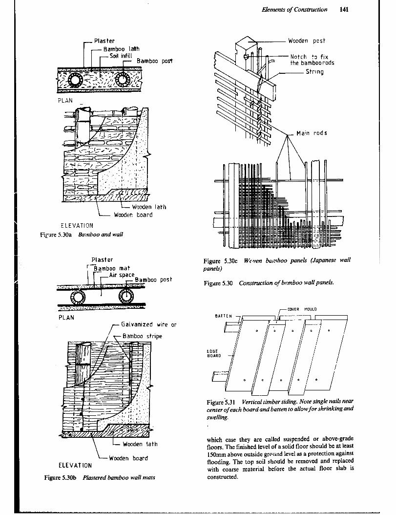
Elements of Construction 141
Firm
Plaster ri- Bamboo lath
r Soil infill Bamboo post
PLAN
ELEVATION
5.30a Bamboo and wall
Plaster
lath
boo post
PLAN
f- Gaivanized wire or
r Bamboo stripe
/- Wooden lath
ELEVATION Wooden board
Figure 5.3Qb Pktstered bamboo wall mats
fi7 Wooden pest
the bamboo rods
Figure 5.30~ Wctven bairboo panels (Japanese wall panels)
Figtire 5.30 Construction qf bamboo wall panels.
COVER MOULO COVER MOULO
14 I I I
O I
Figtirej.3 1 Figtirej.3 1 Vertical timber siding. Note single nails near Vertical timber siding. Note single nails near center of each board and batten to allowfor shrinking and center of each board and batten to allowfor shrinking and swelling.
which case they are called suspended or above-grade floors. The finished level of a solid floor should be at least 150mm above outside grouud level as a protection against flooding. The top soil should be removed and replaced with coarse material beiore the actual floor slab is constructed.

142
Solid or Grade Floors Tamped soil is often satisfactory for the floors of animal shelters and perhaps the homes of subsistence farm fami- lies. They should be designed a little above the ground level outside the building and will be irr.,roved by being stabil- ized with ant-hill clay, cow dung, lime or portland cement.
A discussion of stabilizing materials to use for different circumstances will be found in Chapter 3.
Concrete makes a more durable, harder and cleaner floor. Properly constructed concrete floors can be made dry enough to be used for grain storage or the farm home. Figure 5.32 shows cross sections of stabilized soil and concrete floors. An earth floor suitable for a well-drained site is shown in figure a, while a concrete floor that needs to be moderately dry is shown in b. The single-size coarse aggregate shown in c, is used to prevent capillary move- ment of water to the underside of the floor. The polythene sheet prevents moisture from reachmg the concrete slab and the layer of sand or mortar protects the sheet from being punctured.
kdm shwld
Stone foundation
Floor - 2 layers of tamped stabilized soil (50mm) - Tamped sand - Existing subsoil (topsoil removed) Figure 5.32a Well drained site
Floor - Concrete slab (min. 75mm) - Tamped sand ( IOO- 150mm) - Existing subsoil Figure 5.323 Well drained site
, Expansion joint
Floor - Concrete slab (min. 75mm) - Polythene sheet (750 guage) - Sand (50mm) or mortar (25mm) - Coarse aggregate ( 150-200mm) - Existing subsoil (eu. compacted) Figure 5.32~ Poorly drained site or a very dry floor is required
Figure 5.32 Construction of solidfloors built at ground level.
The concrete mixture chosen to be used in a solid floor will depend on the severity of use and type of loading. For a deep litter building or a subsistence farm dwelling a mix of 1:3:6 by weight may be satisfactory for the light service to which it will be subjected. Floors that will be exposed to heavy loads, as in a bag grain store or a farm repair shop, will need to be stronger. A 1:2:4 should be adequate over a good firm base. The floors in a creamery or slaughterhouse are subjected to acid erosion and require a richer mix of concrete (1:2:3) to give a durable surface.
Pouring Concrete Floors Solid concrete floors should be laid on a level and tam- pered base of hardcore or gravel. On well drained sites also sand or even laterite can be satisfactory. The base layer should be at least 1OOmm thick. While it is desirable for the finished floor level to be at least 150mm above the sur- rounding ground, some fill may be required under the base course. However, fill need to be thouroughly compacted to get the required stability and, generally, it is therefore more satisfactory to increase the thickness of the base course. Any material used for fill or for the base course must be free of organic matter. hence, the excavated top soil must be rejected as fill. If a damp-proof barrier (polythene or a 3mm thick hot bitumen layer) is to be installed, a layer of sand should be spread over the base. Sand can also be used as blinding on a hardcore base to reduce the amount of concrete that ‘disappears’ in the gaps between the stones. Finally, 75 to 150mm timber screeds are put in place to be

Elements of Construction 143
used as guides in striking off and leveling the concrete and reinforcement bars, if advocated, are put in position. The thickness of the slab will depend on the expected loads, the quality of concrete used, reinforcement and the bearing characteristics of the ground.
A floor area that is larger than about lOm2 should be divided into bays for concreting. This will help to prevent the development of shrinkage cracks during the curing process and will allow for each bay to be cast, leveled and finished within a managable time. Square bays are best and 2.5 to 4m sides allow a slab to be cast in one go.
The concrete can then be mixed and p!aced. Regardless of the mix choosen, the concrete should be kept as stiff as possible and the size of the coarse aggregate should not exceed a quarter of the thickness of the slab. The bays are ’ concreted alternately as shown in Figure 5.33. When the first set of bays .have hardened the timber screeds are carefully removed and the remaining bays can be cast.
Once the concrete is placed it is leveled by moving a straight timber along the screeds, or, in case of the second set of bays, the already hardened concrete in adjoining bays, with a sawing action. The concrete can then be “loated’ slightly to smooth the surface. After the initial iight floating, the bay can be left for a few hours before a
final floating to give it a smooth surface. If a non-slip floor *is desired, the concrete can be broomed soon after it is placed to give a rough surface. It will not be touched again until it sets. Once the concrete is set, it should be kept moist for a week.
Suspended or Above-grade Floors
Timber Floors Suspended timber ground-level floors are useful on sloping sites where a great deal of filling would be required to level the ground for a solid floor.
Timber ground-level floors must be well protected against moisture, fungus and termites and must therefore be raised above the ground. The space under such a timber floor should be high enough to ensure good ventilation and to allow a person to crawl underneath for inspecting the floor. Termite protection is more likely to be effective if the floor is raised above the ground at least 45cm.
The supporting piers are frequently built of timber but are better if made of stone, concrete or steel. Hollow
compacted sand
Fmwork ‘edgeboard
Figure 5.33 Concretefloor construction.
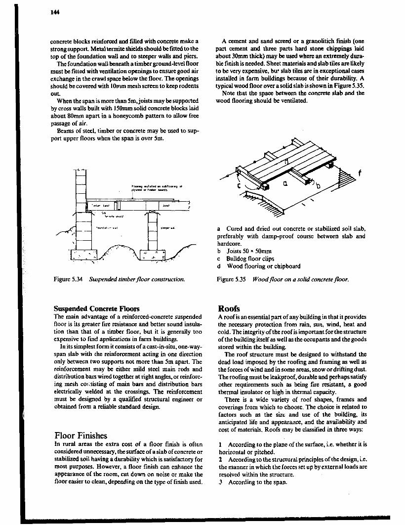
144
concrete blocks reinforced and fdled with concrete make a strong support. Metal termite shields should be fitted to the top of the foundation wall and to steeper walls and piers.
The foundation wall beneath a timber ground-level floor must be fitted with ventilation openings to ensure good air exchange in the crawl space below the floor. The openings should be covered with IOmm mesh screen to keep rodents out.
When the span is more than Sm, joists may be supported by cross walls built with 150mm solid concrete blocks laid about 8Omm apart in a honeycomb pattern to allow free passage of air.
Beams of steel, timber or concrete may be used to sup- port upper floors when the span is over 5m.
Figure 5.34 Suspended timber floor construction.
Suspended Concrete Floors The main advantage of a reinforced-concrete suspended floor is its greater fire resistance and better sound insula- tion than that of a timber floor, but it is generally too expensive to find apnlications in farm buildings.
In its simplest form it consists of a cast-in-situ, one-way- span slab with the reinforcement acting in one direction only between two supports not more than 5m apart. The reinforcement may be either mild steel main rods and distribution bars wired together at right angles, or reinforc- ing mesh co~.sisting of main bars and distribution bars electrically welded at the crossings. The reinforcement must be designed by a qualified structural engineer or obtained from a reliable standard design.
Floor Finishes In rural areas the extra cost of a floor finish is often considered unnecessary, the surface of a slab of concrete or stabilized soil having a durability which is satisfactory for most purposes. However, a floor finish can enhance the appearance of the room, cut down on noise or make the floor easier to clean, depending on the type of finish used.
A cement and sand screed or a granolitich finish (one part cement and three parts hard stone chippings laid about 30mm thick) may be used where an extremely dura- ble finish is needed. Sheet materials and slab tiles arelikely to be very expensive, but slab tiles are in exceptional cases installed in farm buildings because of their durability. A typical wood floor over a solid slab is shown in Figure 5.35.
Note that the space between the concrete slab and the wood flooring should be ventilated.
a Cured and dried out concrete or stabilized soil slab, preferably with damp-proof course between slab and hardcore. b Joists 50 x 50mm c Bulldog floor clips d Wood flooring or chipboard
Figure 5.35 Woodfloor on a solid concretefloor.
Roofs A roof is an essential part of any building in that it provides the necessary protection from rain, sun, wind, heat and cold. The integrity of the roof is important for the structure of the building itself as well as the occupants and the goods stored within the building.
The roof structure must be designed to withstand the dead load imposed by the roofing and framing as well as the forces of wind and in some areas, snow or drifting dust. The roofing must be leakproof, durable and perhaps satisfy other requirements such as being fire resistant, a good thermal insulator or high in thermal capacity.
There is a wide variety of roof shapes, frames and coverings from which to choose. The choice is related to factors such as the size and use of the building, its anticipated lie and appearance, and the availability and cost of materials. Roofs may be classified in three ways:
1 According to the plane of the surface, i.e. whether it is horizontal or pitched. 2 According to the structural principles of the design, i.e. the manner in which the forces set up by external loads are resolved within the structure. 3 According to the span.
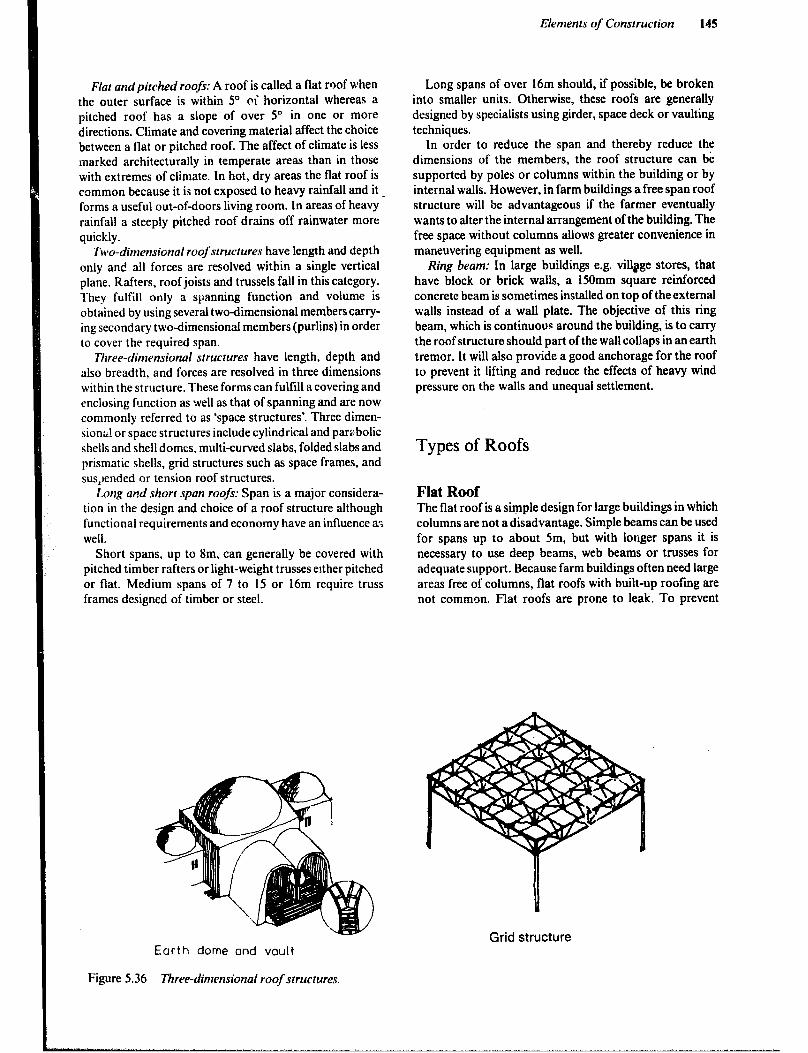
Elements of Construction 145
Flat andpitched roofs: A roof is called a flat roof when the outer surface is within 5” ci horizontal whereas a pitched roof has a slope of over 5” in one or more directions. Climate and covering material affect the choice between a flat or pitched roof. The affect of climate is less marked architecturally in temperate areas than in those with extremes of climate. In hot, dry areas the flat roof is common because it is not exposed to heavy rainfall and it _ forms a useful out-ofdoors living room. In areas of heavy rainfall a steeply pitched roof drains off rainwater more quickly.
Two-dimensional roof structures have length and depth only and all forces are resolved within a single vertical plane. Rafters, roof joists and trussels fall in this category. They fulfill only a spanning function and volume is obtained by using several two-dimensional members carry- ing secondary two-dimensional members (purlins) in order to cover the required span.
Three-dimensional structures have length. depth and also breadth, and forces are resolved in three dimensions within the structure. These forms can fulfill a covering and enclosing function as well as that of spanning and are now commonly referred to as ‘space structures’. Three dimen- sionkl or space structures include cylindrical and par;: bolic shells and shell domes, multi-curved slabs, folded slabs and prismatic shells, grid structures such as space frames, and suspended or tension roof structures.
Long and shorr span roofs: Span is a major considera- tion in the design and choice of a roof structure although functional requirements and economy have an influence as well.
Short spans, up to 8m, can generally be covered with pitched timber rafters or light-weight trusses either pitched or flat. Medium spans of 7 to 15 or 16m require truss frames designed of timber or steel.
Long spans of over 16m should, if possible, be broken into smaller units. Otherwise, these roofs are generally designed by specialists using girder, space deck or vaulting techniques.
In order to reduce the span and thereby reduce the dimensions of the members, the roof structure can bk supported by poles or columns within the building or by internal walls. However, in farm buildings a free span roof structure will be advantageous if the farmer eventually wants to alter the internal arrangement of the building. The free space without columns allows greater convenience in maneuvering equipment as well.
Ring beam: In large ,buildings e.g. village stores, that have block or brick walls, a 150mm square reinforced concrete beam is sometimes installed on top of the external walls instead of a wall plate. The objective of this ring beam, which is continuouc around the building, is to carry the roof structure should part of the wall collaps in an earth tremor. It will also provide a good anchorage for the roof to prevent it lifting and reduce the effects of heavy wind pressure on the walls and unequal settlement.
Types of Roofs
Flat Roof The flat roof is a simple design for large buildings in which columns are not a disadvantage. Simple beams can be used for spans up to about 5m, but with longer spans it is necessary to use deep beams, web beams or trusses for adequate support. Because farm buildings often need large areas free of columns, flat roofs with built-up roofing are not common. Flat roofs are prone to leak. To prevent
Grid structure Earth dome and vouit
Figure 5.36 i%ee-dimensional roof structures.

146
pools of water from collecting on the surface they are usually built with a minimum slope of 1:20 to provide drainage.
The roof structure consists of the supporting beams, decking, insulation and a waterproof surface. The decking, which provides a continuous support for the insulation and surface, can be made of timber boards, plywood, chip- board, metal or asbestoscement decking units or concrete slabs.
The insulation material improves the thermal resistance and is placed either above or below the decking.
The most common design for a waterproof surface is the built-up roof using roofing felt. Thii material consists of a ftbre, asbestos or glass-fibre base which has been impreg- nated with hot bitumen. The minimum pitch recom- mended for built-up roofs is 1:20 or Y which is also near the maximum if creeping of the felt layers is to be prevented.
For flat roofs two or three layers of felt are used, the ftrst being laid at right angles to the slope commencing at the eaves. If the decking is timber the first layer is secured with large flat-head felting nails and the subsequent layers are bonded to it with layers of hot bitumen compound. If the decking is of a material other than timber all three layers are bonded with hot bitumen compound. While it is still hot the final coat of bitumen is covered with a layers of stone chippings to protect the underlying felt, provide additional fire resistance and give increased solar reflec- tion. An application of 20kg/ m2 of 12.5mm chippings of limestone, granite or lightcoloured gravel is suitable.
Where three layers of roofing felt are used and properly laid, flat roofs are satisfactory in rainy areas. However, they tend to be more expensive than other types and require maintenance every few years.
WELTED APRON NAILED TO 3 LAYER BUILT-UP ROOflNG FELT
I ‘M-- -- __-.--- RAINVMER GUTTER I---
Figure 5.37 Built-up roofing felt.
Earth Roof Soil-covered roofs have good thermal insulation and high capacity for storing heat. The traditional earth roof is subject to erosion during rain, requires steady maintenance to prevent leakage. The roof is laid rather flat with a slope of 1:6 or less.
The supporting structure should be generously designed of preservative - treated or termite-resistant timber of poles, and inspected and maintained periodically, as a sudden collapse of this heavy structure could cause great harm. The durability of the mud cover can be improved by stabilizing the top soil with cement, and it can be water- proofed by placing a plastic sheet under the soil. Figure 5.38 and Figure 5.39 shows two types of earth roofs.
Figure 5.38 Cross-section of an improved earth roof:
Wood sheothmg Supper t tng beams
Figure 5.39 Earth roof with bitumen waterproofing.
However, the introduction of these improvements adds considerably to the cost of the roof. The improved earth roof therefore is a doubtful alternative for low-cost roofing and should be considered only in dry areas where soil-roof construction is known and accepted.
Monopitched Roof Monopitch roofs slope in only one direction and have no ridge. They are easy to build, are comparatively inexpen- sive and are recommended for use on many farm buildicgs. The maximum span with timber members is about 5m, thus wider buildings will require intermediate supports. Also wide buildings with this type of roof will have a high front wall which increases the cost and leaves the bottom of that wall relatively unprotected by the roof overhang. When using corrugated steel or asbestos-cement sheets, the slope should not be less that 1:3 (17 to 18“). Less slope may cause leakage as strong winds can force water up the slope.

The rafters can be of round or sawn timber or when wider spans are required, of timber or steel trusses which can be supported on a continuous wall or on posts. The inclined rafters of a pitched roof meet the wall plates at an angle and their load tends to make them slide off the plate. To reduce this tendency and to provide a horizontal surface through which the load may be transferred to the wall without excessively high compressive forces, the rafters in pitched roofs are notched over the plates, To avoid weak- ening of the rafter, the depth of the notch (seat cut) should not exceed one-third that of the rafter. When double rafters are used a bolted joint is an alternative. The rafters should always be thoroughly fared to the walls or posts to resist the uplifting forces of the wind.
Double-pitched (Gable) Roof A gable roof normally has a centre ridge with a slope to either side of the building. With this design a greater free span (7 to 8m) is possible with timber rafters than with a monopitch roof. Although the monopitch design may be
BEAM ~OPWNAL) 7
Elements of Construction 141
less expensive in building widths up to lOm, the inconven- ience of many support columns favors the gable roof. The gable roof may be built in a wide range of pitches to suit any of several different roofing materials. Figure 5.41 shows a number of the elements that are associated with a gable roof. The following description is keyed to the figure:
0 The bottom notch in the rafter that rests on the plate is called the seat cut or plate cut. 0 The top cut that rests against the ridge board is called the’ridge cut. 0 The line running parallel with the edge of the rafter from the outer point of the seat cut to the centre of the ridge is called the work line. 0 The length of the rafter is the distance along the work line from the intersection with the comer of the seat cut to the intersectionwith the ridge cut. l If a ridge bourd is used, half the thickness of the ridge board must be removed from the length of each rafter. 0 The rise of the rafter is the vertical distance from the top of the plate to the junction of the workline at the ridge.
\
f? ‘pe
POST
RARER G Yb BEAM
Tcothed plate ConneCtOr
Installed !n both joints
Post I
TJ
HALF LAPPED JOINT IN ROUND TIMBER TO EXTEND LENGHT OF MEMBER.
Figure 5.40 Pole framing for a monopitch building.

Decking
FClSCh
board
-l-J- Rafter I tail
Figure 5.41 Gable roof design.
0 The run of the rafter is the horizontal distance from the outside of the plate to the centreline of the ridge. 0 The portion of the rafter outside the plate is called the rafter tail. l The collar beam or cross tie prevents the load on the rafters from forcing the walls apart which would allow the rafter to drop at the ridge. The lower the collar beam is placed, the more effective it will be. Occasionally small buildings with strong walls are designed without collar beams. The only advantage of this design is the clear space all the way to the rafters. Scissors trusses, as shown in Figure 5.51, at the same time allow some clear space. 0 The right-hand rafter shows purlins spanning the raf- ters and supporting a rigid roofing material such as galvan- ized steel or asbestos-cement roofing. l The left-hand rafter is covered with a tight deck made of timber boards plywood or chipboard. It would be covered with a flexible roofing material such as roll asphalt roofing. 0 The left-hand eave is enclosed with a vertical fucia board and a horizontal sofit board. l The pitch is shown on the small triangle on the right side.
The angle of the ridge and seat cuts can be laid out on the rafter using a steel carpenter’s square and the appropriate rise and run values both on the outside of the blades or both on the inside of the blades of the square, 30 and 20cm in the example in Figure 5.42. The length may be found with the Pythagorean theorem using the rise and run of the rafter. The length is measured along the workline.
When a gable roof must span more than 7 to 8m, trusses are usually chosen to replace plain rafters. For large spans the trusses will save on total material used and provide a stronger roof structure. For solid roof decks the trusses are usually designed to be spaced approximately 600mm on
centre, while for rigid roofing mounted on purlins, a truss spacing of 1200mm or more is common.
The agricultural extension can provide designs for the spans, spacings and loads that are commonly found on farms. Also, in Chapter 4 the theory of truss design is discussed. Figure 5.43 illustrates a simple truss design.
Lenght IS A to B rorkltne
Figure 5.42 Laying out a common rqfier.
Figure 5.43 A l ‘w” truss design.
Due to large negative windloads, roofs are in danger of being blown off. Therefore it& important to anchor the roof trusses properly to the wall plates. This can be done with strips of hoop iron, one strip tying the wall plate to the
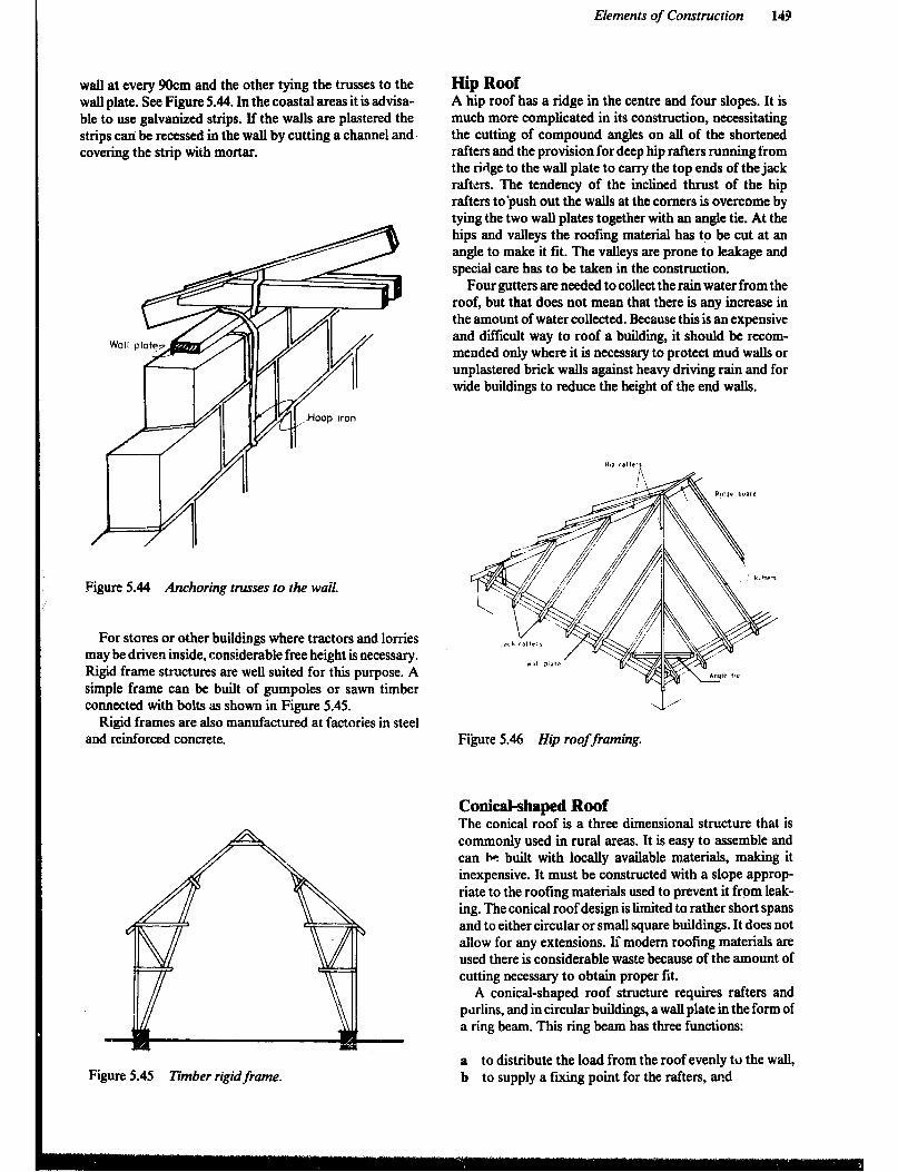
Elements of Construction 149
wall at every 9Ocm and the other tying the trusses to the walI plate. See Figure 5.44. In the coastal areas it is advisa- ble to use galvanized strips. If the walls are plastered the strips can be recessed in the wall by cutting a channel and. covering the strip with mortar.
Figure 5.44 Anchoring trusses to the wail.
For stores or other buildings where tractors and lorries may be driven inside, considerable free height is necessary. Rigid frame StNCtUmS are weU Suited for this purpose. A simple frame can be built of gumpoles or sawn timber connected with bolts as shown in Figure 5.45.
Rigid frames are also manufactured at factories in steel and reinforced concrete.
Figure 5.45 Timber rigid frame.
Hip Roof A hip roof has a ridge in the centre and four slopes. It is much more complicated in its construction, necessitating the cutting of compound angles on all of the shortened rafters and the provision for deep hip rafters running from the ridge to the wall plate to carry the top ends of the jack rafters. The tendency of the inclined thrust of the hip rafters to-push out the walls at the comers is overcome by tying the two wall plates together with an angle tie. At the hips and valleys the roofing material has to be cut at an angle to make it fit. The valleys are prone to leakage and special care has to be taken in the construction.
Four gutters are needed to collect the rain water from the roof, but that does not mean that there is any increase in the amount of water collected. Because this is an expensive and difficult way to roof a building, it should be recom- mended only where it is necessary to protect mud walls or unplastered brick walls against heavy driving rain and for wide buildings to reduce the height of the end walls.
Figure 5.46 Hip roof framing.
Conical-shaped Roof The conical roof is a three dimensional structure that is commonly used in rural areas. It is easy to assemble and can hn built with locally available materials, making it inexpensive. It must be constructed with a slope approp riate to the roofing materials used to prevent it from leak- ing. The conical roof design is limited to rather short spans and to either circular or small square buildings. It does not allow for any extensions. If modem roofing materials are used there is considerable waste because of the amount of cutting necessary to obtain proper fit.
A conical-shaped roof structure requires rafters and prlrlins, and in circular buildings, a wall plate in the form of a ring beam. This ring beam has three functions:
a to distribute the load from the roof evenly to the wall, b to supply a fixing point for the rafters, and
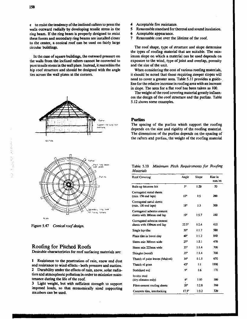
150
c to resist the tendency of the inclined rafters to press the walls outward radirdly by developing tensile stress in the ring beam. If the ring beam is properly designed to resist these forces and secondary ring beams are installed closer to the center, a conical roof can be used on fairly large circular buildings.
In the case of square buildings, the outward pressure on the walls from the inclined rafters cannot he converted to pure tensile stress in the walI plate. Instead, it resembles the hip roof structure and should be designed with the angle ties across the wall plates at the comers.
Figure 5.47 Conical roof design.
Roofing for Pitched Roofs Desirable characteristics for roof surfacing materials are:
1 Resistance to the penetration of rain, snow and dust and resistance to wind effects -both pressure and suction. 2 Durability under the effects of rain, snow, solar radia- tion and atmospheric pollution in order to minimize main- tenance during the life of the roof. 3 Light weight, but with sufficient strength to support imposed loads, so that economically sized supporting members can be used.
4 Acceptable fire resistance. 5 Reasonable standard for thermal and sound insulation. 6 Acceptable appearance. 7 Reasonable cost over the lifetime of the roof.
The roof shape, type of structure and slope determine the types of roofing material that are suitable. The min- imum slope on which a material can be used depends on exposure to the wind, type of joint and overlap, porosity and the size of the unit.
When considering the cost of various roofing materials, it should be noted that those requiring steeper slopes will need to cover a greater area. Table 5.11 provides a guide-, line for the relative increase in roofing area with an increase in slope. The area for a flat roof has been taken as 100.
The weight of the roof covering material greatly infhren- ces the design of the.roof structure and the purlins. Table 5.12 shows some examples.
PlUlii The spacing of the purlins which support the roofing depends on the size and rigidity of the roofing material. The dimensions of the purlins depends on the spacing of the rafters and purlins, the weight of the roofing material
Table 5.10 Minimum Pitch Requirements for Roofing Materials
Roof Covering Angle Slope Rise in mm/m
Built-up bitumen felt
Corrugated metal sheets (min. 150 end laps)
Corrugated metal sheets (min. 100 end laps)
Corrugated asbestos cement sheets with 300mm end lap
Corrugated asbestos cement sheets with 150mm end lap
Single lap tiles
Plain tiles in burnt clay
Slates min 3Wmm wide
Slates min 225mm wide
Shingles (wood)
Thatch of pabn leaves (Makuti)
Thatch of grass
Stabilized soil
In-situ mud (dry climates only)
Fibreament roofing sheets
Concrete tiles, interlocking
3” 1:20 50
120 I:5 200
18” I:3 300
IO0 1 E5.7 180
22.5O 112.4 410
300 1:1.7 580
w 1:1.2 840
2Y 1:2.1 470
35O 1:1.4 700
35” 1:1.4 700
34O 1:1.5 670
45O I:1 loo0
!T 1:6 170
6” I:10 100
2b 1~2.8 360
17.Y 1:3.2 320

and the loading on the roof from wind, persons construct- ing and maintaining the roof and in some areas snow. Timber, round or sawn, is the most common material used for purlins since roofing material can be easily attached by nailing. Where the spacing of trusses is in excess of 25 to 3,0m, timber purlins are not feasible and steel profiles are used instead. The profile can be an angle iron or a Z-profile made from plain iron sheets:
Small units such as slates, tiles and shingles are affixed to closely spaced battens of rather small section which means that the rafters must be closely spaced.
Table 5. I 1 Relative Areas of Roofs of Various Sloped
.Angle Slope Relative Area of Roofing
0” - 100 lo* 15.7 102 l!P 1:3.7 104 20” 1~2.7 106 25” 1:2.1 110 30” 1:1.7 115 35O 1:1.4 122 4o” 1:1.2 131 45” 1:l.O 141 50” ! iO.8 156 55” 1:0.7 174 tit-P 1:0.6 200
Table 5.12 Weights of Roofing Materials
Material Weight
Corrugated ahuninium sheet 2.5-5 depending on gauge Corrugated steel sheets 6-9 depending on gauge Corrugated steel sheets,laid 8- 12 depending on gauge Asbestos cement sheets 14 Asbestos cement sheets, laid 16 Slates, laid 40 Tiles, laid 65
Thatch Thatch is a very common roofing material in rural areas. It has good thermal insulating qualities and helps to maintain rather uniform temperatures within the building even when outside temperatures vary considerably. The level of noise from rain splashing on the roof is low but during long, heavy rains some leakage may occur. Although thatch is easy to maintain, it may also harbor insects, pests and snakes.
Elements of Construction 151
A number of different plant materials such as grass, reeds, papyrus, palm leaves and banana leaves are suitable and inexpensive when locally available. Although the materials are cheap, thatching is rather labour intensive and requires some skill.
The durability of thatch is relatively low. In the case of grass, a major repair will be required every 2 to 3 years, but when well laid by a specialist and maintained, it can last for 20 to 30 years or longer. The supporting structure of wooden poles or bamboo, although simple, must be strong enough to carry the weight of wet thatch. The use of thatch is limited to rather narrow buildings since the supporting structure would otherwise be complicated and expensive and the rise of the roof very high due to the necessity of a very steep slope. Palm leaves should have a slope of at least. 1: 1.5, but preferably 1: 1 and grass thatch a minimum of 1: 1 but preferably 1:0.6. Increasing the slope will improve the durability and reduce the risk of leakage. The risk of fire is extremely high but may be reduced by treatment with a fire retardant as described later.
Grass Thatch Grass for thatching should be:
l Hard, fibrous and tough with a high content of silicates and oils and a low content of easily digestible nutrients like carbohydrates, starches and proteins. 0 Free of seeds and harvested at the right time. l Straight and have thin leaves and at least 1 metre long.
Proper thatching procedure requires that:
0 Stems be parallel, densely packed, with the cut side pointing outward. 0 A steeply sloping roof frame of 45“ or more be used. l The eaves are low to offer protection for the walls. l For best results the roof shape be conical, pyramidical or hipped in shape rather than double pitched where the verges present weak points.
For easy handling the grass is tied into bundles. The thatching is started from the eaves in widths of about lm. A number of.grass bundles are put next to each other on the roof, with the base of the stems to the bottom. The grass is tied to the purlins with bark fibre or preferably tarred sisal cord. In subsequent layers the bundles are laid to overlap the layer underneath by half to two-thirds of their length, which means there will be two to three la!. ers in the finished thatch.
A long needle is used to push the string through and tie the bundles of grass onto the roof-laths. Then the bundles themselves are untied and with the hands the grass is pushed into the right position giving a smooth surface to the roof. Then the string is pulled and this fixes the grass securely in place. Another method leaves the bundles of grass as they are, which gives the roof a stepped surface. The thickness of the new thathh layers varies between 15 and 20cm but later on this will become somewhat thinner because of settling.

152
Figure 5.48 l?zatching with grass.
Stitch at bottom of first thatch on lowest batten. The second layer must overlay the stitching of the first row and include the top section ofthe underneath layer in the actual stitch. it is better to have each layer held by 3 rows of stitching. The stitching of every row must be completely covered by the free ends of the next layer above it.
The grass or straw is bound in bundles to the battens forming thatch boards. These boards are manufactured on the ground and bound to the rafters beginning at the eaves and continuing to the ridge. Each board covers with it’s free ends the board underneath.
SEWN THATCHING
Palm Leaf Thatch ‘Makuti) Palm leaves are often ‘Ied into makuti mats which are used for the roof covering. They consist of palm leaves tied to a rib (part of the stem of the palm leaf) using the dried fibre of Doum palm leaves or sisal twine.
The mars are laid on the rafters (round poles) and the stems tied to the rafters with sisal twine. The mats are usually produced to a standard size of 600 x 6OOmm and laid with a 1COmm side lap, thus requiring a rafter spacing of 5OOmm. For a good quality mat 6OOmm wide, an aver- age of 75 blades will be required. Spacing up the roof slope, i.e. the distance between the ribs of the makuti mats, is usually 150 to IO&urn, thus forming a4 to 6 layer coverage, 5 to 8cm thick.
Figure 5.51 shows three types of ridge caps that can be used on thatch roofs.
Papyrus Thatch First a papyrus mat is placed on top of the purlins, then a layer of black polythene and finally another one or two papyrus mats to complete the roof. These materials are fixed to the purlins with nails and iron wire. Nails are fixed to the purlin at IS to 20cm spacing and the iron wire is then stretched over the top of the papyrus mat and secured to the nails. The papyrus has a life span of about three years but that can be extended by treating the papyrus with a water-repellant paint.
STIRMNG
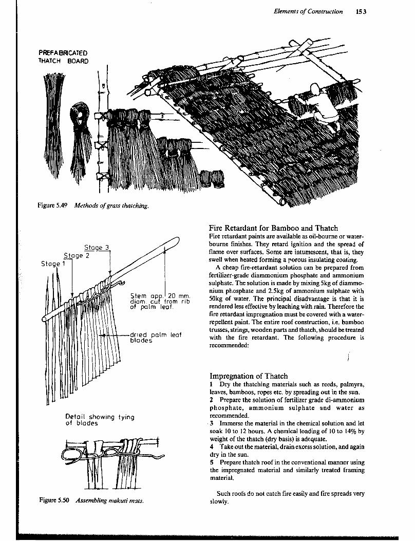
Elements of Construction 153
PRFABFUCATED
THATCH BOARD
Figure 5.40 Methods of grass thatching.
Detail showing tying of blades
Figure 5.50 Assembling makuti mats.
Fire Retardant for Bamboo and Thatch Fire retardant paints are available as oil-boume or water- bourne finishes. They retard ignition and the spread of flame over surfaces. Some are intumescent, that is, they swell when heated forming a porous insulating coating.
A cheap fire-retardant solution can be prepared from fertilizer-grade diammonium phosphate and ammonium sulphate. The solution is made by mixing 5kg of diammo- nium phosphate and 2.5kg of ammonium sulphate with 50kg of water. The principal disadvantage is that it is rendered less effective by leaching with rain. Therefore the fire retardant impregnation must be covered with a water- repellent paint. The entire roof construction, i.e. bamboo trusses, strings, wooden parts and thatch, should be treated with the fire retardant. The following procedure is recommended:
Impregnation of Thatch 1 Dry the thatching materials such as reeds, palmyra, leaves, bamboos, ropes etc. by spreading out in the sun. 2 Prepare the solution of fertilizer grade di-ammonium phosphate, ammonium sulphate and water as recommended. 3 Immerse the material in the chemical solution and let soak 10 to 12 hours. A chemical loading of 10 to 14% by weight of the thatch (dry basis) is adequate. 4 Take out the material, drain excess solution, and again dry in the sun. 5 Prepare thatch roof in the conventional manner using the impregnated material and similarly treated framing material.
Such roofs do not catch fire easily and fire spreads very slowly.
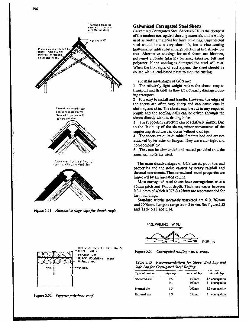
154
Thatched ridgecap secured to purlms with tarred string
Purlins wire0 or nallcd to . truss. - max 600 mm centrer-to depend. on lenghof grass
Cement reinforced ridge rap on expanded metal Secured to purlins wI th aalvanlzed wire
Galvantzed ran sheet tied to purlIns with galvanized wire
Figure 5.51 Alremative ridge caps for thatch roofs.
Galvanized Corrugated Steel Sheets Galvanized Corrugated Steel Sheets (GCS) is the cheapest of the modem corrugated sheeting materials and is widely used as roofing material for farm buildings. Unprotected steel would halt a very short lie, but a zinc coating (galvanizingj adds substantial protection at a relatively low cost. Alternative coatings for steel sheets are bitumen, polyvinyl chloride (plastic) on zinc, asbestos, felt and
.polyester. Ii the coating is damaged the steel will rust. When the first signs of rust appear, the sheet should be coilted with a lead-based paint to stop the rusting.
Tne main advantages of GCS are: 1 The’ relatively light weight makes the sheets easy to transport and flexible so they are not easily damaged dur- ing transport. 2 It is easy to install and handle. However, the edges of the sheets are often very sharp and can cause cuts in clothing and skin. The sheets may b e cut to any required length and the roofing nails can be driven through the sheets directly without drilling holes. 3 The supporting structure can be relatively simple. Due to the flexibility of the sheets, minor movements of the supporting structure can occur without damage. 4 The sheets are quite durable if maintained and are not attacked by termites or fungus. They are x%:‘itr-tight and non-combustible. 5 They can be dismantled and reused provided that the same nail holes are used.
The main disadvantages of GCS are its poor thermal properties and the noise caused by heavy .rainfall and thermal movements. The thermal and sound properties are improved by an insulated ceiling.
Most corrugated steel sheets have corrugations with a ‘76mm pitch and 19mm depth. Thickness varies between 0.3-l .6mm of which 0.375-0.425mm are recommended for farm buildings.
Standard widths normally marketed are 610, 762mm and 1OOOmm. Lengths range from 2 to 4m. See figure 5.53 and Table 5.13 and 5.14.
PREVAILING WIND e
IRON WIRE TWISTED ONTO NAILS N THE PURLIN
PAWRUS MAT BLACK POLYTHENE SHEET PAWRUS MAT
NAIL i , +-PURLIN
Figure 5.52 Papyrus-polythene roof:
Figure 5.53 Corrugoted roofing with overlap.
Table 5.13 Recommendations for Slope, End Lap and Side Lup for Corrugated Steel Rofjing
Type of position
Sheltered site
Normal site
Exaosed site
min end lap min side lap
15omm I .5 corrugation IOOmm I corrugation
~IOOmm I .5 corrugation
15Omm 2 cormnation
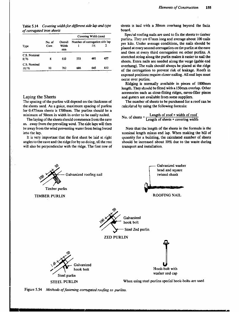
Table 5.14 Covering width for d-rent side lop and type of corrugated iron sheets
Type
C.S. Nominal E/76
C.S. Nominal IO/76
No. of corr.
8
10
Covering Width (mm)
Overall Number of corrugation side lap Width I 1% 2 mm
610 533 495 457
762 686 645 610
Laying the Sheets The spacing of the purlins will depend on the thickness of the sheets used. As a guiue, maximum spacing of purlins for 0.47Smm sheets is 1SOOmm. The purlins should be a minimum of SOmm in width in order to be easily nailed.
The laying of the sheets should commence from the eave an_ away from the prevailing wind. The side laps will then be away from the wind preventing water from being forced into the lap.
It is very important that the first sheet be laid at right angles to the eave and the ridge for by so doing, all the rest will also be perpendicular with the ridge. The first row of
Galvanized roofing nail
Timber purlin
TIMBER PURLIN
Elements of Construction 155
sheets is laid with a SOmm overhang beyond the facia board.
Special roofing nails are used to fix the sheets to timber purlins. They are 67mm long and average about 100 nails per kilo. Under average conditions, the nails should be placed at every second corrugation on the purlin at the eave and then at every third corrugation on other purlins. A stretched string along the purlin makes it easier to nail the sheets. Extra nails are needed along the verge (gable end overhang). The nails should always be placed at the ridge of the corrugation to prevent risk of leakage. Roofs in exposed positions require closer nailing. All end laps must occur over purlins.
Ridging is nbrmally available in pieces of 18OOmm length. They should be fitted with a 1SOmm overlap. Other accessories such as close-fitting ridges, eaves-filer pieces and gutters are available from some suppliers.
The number of sheets to be purchased for a roof can be calcrrlatod by using the following formula:
No. of sheets = Length of roof x width of roof
Length of sheets x covering width
Note that the length of the sheets in the formula is the nominal length minus end lap. When making the bii of quantity for a building, the calculated number of sheets should be increased about 10% due to the waste during transport and installation.
Galvanized washer head and square twisted shank .I
ROOFING NAIL
ZED PURLIN
’ Steei purlin
4 -bdlt with Hook
washer and cap
STEEL PURLIN When using steel purlins special hook-bolts are used
Figure 5.54 Methods of fmtening corrugated roofing to purlins.
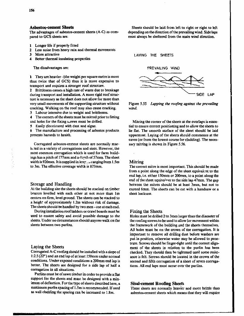
156
Asbestopcement Sheets The advantages of asbestosament sheets (A-C) as com- pared to GCS sheets are:
1 Longer life if properly fitted 2 Less noise from heavy rain and thermal movements 3 More attractive 4 Better thermal insulating properties
The disadvantages are:
1 They are heavier - (the weight per square metre is more than twice that of GCS) thus it is more expensive to transport and requires a stronger roof structure. 2 Brittleness causes a high rate of waste due to breakage during transport and installation. A more rigid roof struc- ture is necessary as the sheet does not allow for more than very small movements of the supporting structure without cracking. Walking on the roof may also cause cracking. 3 Labour intensive due to weight and brittleness. 4 The comers of the sheets must be mitred prior to fitting and holes for the fling sirews must be drilled. S Easily discoloured with dust and algae. 6 The manufacture and processing of asbestos products presents hazards to health.
Corrugated asbestos-cement sheets are normally mar- kr ted in a variety of corrugations and sizes. However, the most common corrugation which is used for farm build- ings has a pitch of 177mm and a depth of S7mm. The sheet width is 920mm. It is supplied in len5 -:i ranging from 1 .Sm to 3m. The effective coverage width is 873mm.
Storage and Handling At the building site the sheets should be stacked on timber bearers levelled with each other at not more than lm centres on firm, level ground. The sheets can be stacked to a height of approximately 1.2m without risk of damage. The sheets should be handled by two men -one at each end.
During installation roof ladders or crawl boards must be used to ensure safety and avoid possible damage to the sheets. Under no circumstances should anyone walk on the sheets between two purlins.
Laying the Sheets Corrugated A-C roofing should be installed with a slope of 1:2.S (22’) and an end lap of at least ISOmm under normal conditions. Under exposed conditions a 200mm end lap is better. The sheets are designed for a side lap of half a corrugation in all situations.
Purlins must be of sawn timber in order to provide a flat support for the sheets and must be designed with a min- imum of deflection. For the type of sheets described here, a maximum purlin spacing of l.Sm is recommended. Bused as wall cladding the spacing can be increased to 1.8m.
Sheets should be laid from left to right or right to left depending on the direction of the prevailing wind. Side laps must always be sheltered from the main wind direction.
LAYING THE SHEETS
PREVAILING WIND C
- SIDE LAP
Figure 5.55 Lapping the roofing against the prevailing wind.
Mining the comer of the sheets at the overlaps is essen- tial to ensure correct positioning and to allow the sheets to lie flat. The smooth surface of the sheet should be laid uppermost. Laying of the sheets should commence at the eaves (or from the lowest course for cladding). The neces- sary mining is shown in Figure 5.56.
Mitring The correct mitre is most important. This should be made from a point along the edge of the sheet equivalent to the end lap, i.e. either 1SOmm or 2OOmm, to a point along the end of the sheet aquivatent to the side lap 47mm. The gap between the mitres should be at least 3mm, but not to exceed 6mm. The sheets can be cut with a handsaw or a sheet hacksaw.
Fixing the Sheets Holes must be drilled 2 to 3mm larger than the diameter of the roofing screws to be used to allow for movement within the framework of the building and the sheets themselves. All holes must be on the crown of the corrugation. It is important to remove all drilling dust before washers are put in position, otherwise water may be allowed to pene- trate. Screws should be finger-tight until the correct align- ment of the sheets in relation to the purlin has been checked. They should then be tightened until some resist- ance is felt. Screws should be located in the crown of the second and fifth corrugation of a sheet of seven corruga- tions. All end laps must occur over the purlins.
Sisal-cement Roofing Sheets These sheets are normally heavier and more brittle than asbestos-cement sheets which means that they will require
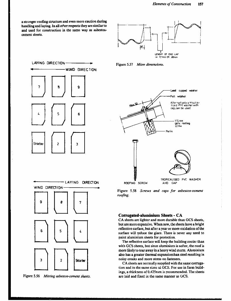
Elements of Construction 157
a stronger roofing structure and even more caution during handling and laying. In all other respects they are similar to and used for construction in the same way as asbestos- cement sheets.
LAYING DIRECTION H
N WIND DIRECTION
C Starter ocl 2 3
4 LAYING MRECTION
WIND DIRECTION b
lITIDa
F) n n
Figure 5.56 Mitring asbestos-cement sheets.
LENGtff OF END LA? 1.0 l%nm OR 3Rmm
Figure 5.57 Mitre dimensions.
Alternatively a tropica- Iired PVC washerwlth cap,can be used
--115mm gnlv. roofing screw
Purlin
8
0
TROPICALISED F’VC WASHER
ROOFING SCREW AND CAP
Figure 5.58 Screws and caps for asbestos-cement roofing.
Corrugated-aluminiu Sheets - CA CA sheets are lighter and more durable than GCS sheets, but are more expensive. When new, the sheets have a bright reflective surface, but after a year or more oxidation of the surface will r.educe the glare. There is never any need to paint aluminium sheets for protection.
The reflective surface will keep the building cooler than with GCS sheets, but since aluminium is softer, the roof is more likely to tear away in a heavy wind storm. Aluminium also has a greater thermal expansionthan steel resulting in noisy creaks and more stress on fasteners.
CA sheets are normally supplied with the same corruga- tion and in the sa.me sizes ?& GCS. For use in farm build- ings, a thickness of 0.42Smm is recommended. The sheets are laid and fvred in the same manner as GCS.
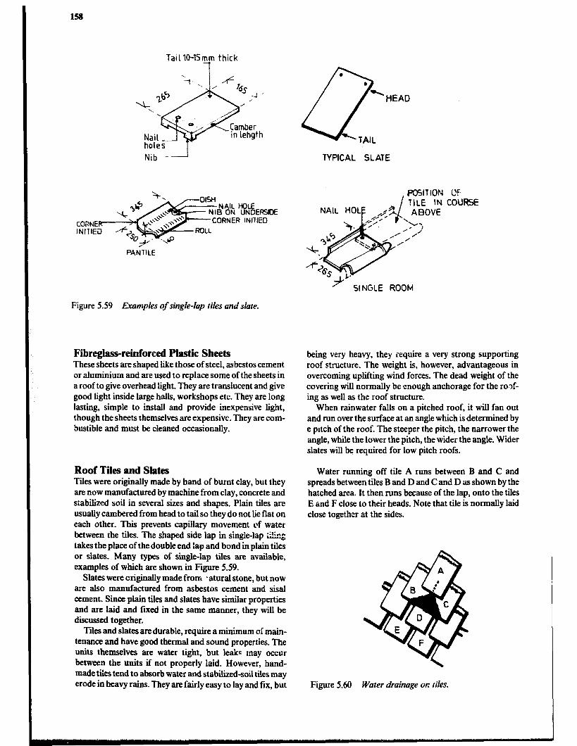
Tail lo-1Syn thick
CCBNER INlllEiI
Nib -I TYPICAL SLATE
/ SI NGLE ROOM
Figure 5.59 Examples of single-lap tiles and slate.
Filrreglass-reinforced Plastic Sheets These sheets are shaped lie those of steel, asbestos cement or aluminium and are used to replace some of the sheets in a roof to give overhead light. They are translucent and give good light inside large halls, workshops etc. They are long lasting, simple to install and provide inexpensive light, though the sheets themselves are expensive. They are com- bustible and must be cleaned occasionally.
Roof Tiles and Slates Tiles were originally made by hand of burnt clay, but they are now manufactured by machine from clay, concrete and stabilized soil in several sixes and shapes. Plain tiles are usually cambered from head to tail so they do not lie flat on each other. This prevents capillary movement of water between the tiles. The shaped side lap in single-lap Zng takes the place of the double end :ap and bond in plain tiles or slates. Many types of single-lap tiles are available, examples of which are shown in Figure 5.59.
Slates were originally made from *atural stone, but now are also manufactured from asbestos cement and sisal cement. Since plain tiles and slates have similar properties and are laid and fixed in the same manner, they will be discussed together.
Tiles and slates are durable, require a minimum of main- tenance and have good thermal and sound properties. The units themselves ate water tight, but leaks may occur between the units if not properly laid. However, hand- made tiles tend to absorb water and stabilized-soil tiles may erode in heavy rains. They are fairly easy to lay and fix, but
being very heavy, they require a very strong supporting roof structure. The weight is, however, advantageous in overcoming uplifting wind forces. The dead weight of the covering will normally be enough anchorage for the ro.>f- ing as well as the roof structure.
When rainwater falls on a pitched roof, it will fan out and run over the surface at an angle which is determined by e pttch of the roof. The steeper the pitch, the narrower the angle, while the lower the pitch, the wider the angle. Wider slates will be required for low pitch roofs.
Water running off tile A runs between B and C and spreads between tiles B and D and C and D as shown by the hatched area. It then runs because of the lap, onto the tiles E and F close to their heads. Note that tile is normally laid close together at the sides.
Figure 5.60 Water drainage on tiles.

Elements of Construction 159
Table 5.15 Slate and 7% Size, Pitch and Lup
Min. Min. Minimum lap (mm)
si?z Pitch Slope Normal sites Exposed sites
Slates
305 x 205mm 45O I:1 65 65
330 x 180mm 40° 1:l.Z 65 65
405 x 2OSmm 35” 1:1.4 70 70
510 x 255mm 30° 1:1.7 75 75
6!Ox 305mm 25” 1:2.1 90 loo
610 x 355mm 22.5’ 1~2.4 100 N/A
Plain Tiles*
Concrete and Machine pressed 350 1:1.4 65 75
Stabilized soil 45’ I:1 65 75
l standard size 265 x 165mm. laid with 32mm side lap
Double course of Ridge tile bedded in mortar
only the bottom st
Double course
L - Fascia board
For head nalled slates. gauge= -- length of slates-llap+ZSmm)
2
Figure 5.61 Installation of slates.
Plain tiling and slating provides an effective barrier to rain but wind and dust penetrate through the gaps between the units. Therefore boarding or sheeting may be placed under the battens on which the tiles or slates are to be hung. Roofing felt is the material most commonly used for this purpose.
In laying piain tile or slate there must always be at least two thicknesses covering any part of the roof, butt jointed at the side and placed so that no vertical joint is imme- diately over another vertical joint in the course below. To ensure this, shorter length units are required at the eaves and the ridge and each alternate course is commenced with a tile or slate of one-and-a-half units in width. The ridge is capped with special units bedded in cement mortar.
The hips can be covered with a ridge unit, in which case the plain tiling or slating is laid underneath and mitred at the hip. Valleys can be formed by using special units.
Plain tiles are ordinarily fixed with two galvanized nails in each tile at every fourth or fifth course. However, in very exposed positions every tile should be nailed.
Slates, which do not have nibs securing them to the battens, should be nailed twice in every unit. Plain tiles and small slates are .nailed at the head while long slates are sometimes nailed at the centre to overcome vibrations caused by the wind. Centre nailing is mainly used for pitches below 35O and in the courses close to the eave.
Top batten (40 x 20 mm) other battens 20 x 20mm
Ridge cap bedded
ver each batten
felt for extra wind protection if required
Tiles nailed to batten in every 4thc*ur*
Figure 5.62 Plain tile roof:
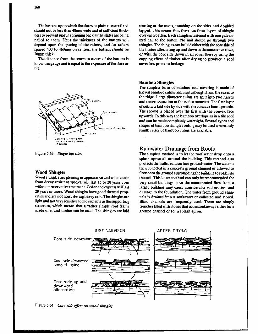
160
The battens upon which the slates or plain tiles are fixed should not be less than 40mm wide and of sufficient thick- ness to prevent undue springing back as the slates are being nailed to them. Thus the thickness of the battens will depend upon the spacing of the rafters, and for rafters spaced 400 to 46Omm on centres, the battens should be 20mm thick.
The distance from the centre to centre of the battens is known as gauge and is equal to the exposure of the slate or tile.
Figure 5.63 Single-lap tiles.
Wood Shingles Wood shingles are pleasing in appearance and when made from decay-resistant species, will last 15 to 20 years even without preservative treatment. Cedar and cypress will lasi
20 years or more. Wood shingles have good thermal prop- erties and are not noisy during heavy rain. The shingles are light and not very sensitive to movements in the supporting structure, which means that a rather simple roof frame made of round timber can be used. The shingles are laid
starting at the eaves, touching on the sides and doubled Iapped. This means that there are three layers of shingle over each batten. Each shingle is fastened with one galvan- ized nail to the batten. No nail should go through two shingles. The shingles can be laid either with the core side of the timber alternating up and down in the successive rows, or with the core side down in all rows, thereby using the cupping effect of timber after drying to produce a roof cover less prone to leakage.
Bamboo Shingles The simplest form of bamboo roof covering is made of halved bamboo culms running full length from the eaves to the ridge. Large diameter culms are split into two halves and the cross section at the nodes removed. The first layer of culms is laid side by side with the concave face upwards. The second is placed over the first with the convex face upwards. In this way the bamboo overlaps as in a tile roof and can be made completely watertight. Several types and shapes of bamboo shingle roofing may be used where only smaller sizes of bamboo culms are available.
Rtinwater Drainage from Roofs The simplest method is to let the roof water drop onto a splash apron all around the building. This method also protects the walls from surface ground-water. The water is then collected in a concrete ground channel or allowed to flow onto the ground surrounding the building to soak into the soil. This latter method can only be recommended for very small buildings since the concentrated flow from a larger building may cause considerable soil erosion and damage to the foundation. The water from ground chan- nels is drained into a soakaway or collected and stored. Blind channels are frequently used. These are simply trenches filled with stones that act as soakaways either for a ground channel or for a splash apron.
AFTER DRYING I I I
JUST NAILED ON
Core side downwa
Core side downward spaced laymg
Core side up and downward alternating
Figure 5.64 Core-side e&t on wood shingles.

Elements of Construction 161
Ahrrnative nails can be made of dry bamboo 4/4mm aud 4cm long.
The shingles are cut of cross sections @a& F (70cm long) of a straight gram timber log. The bark and the core are thrown away. The shingles are about 2cm thick and 70cm long. The width will vary.
The shingles are laid from the eaves to the ridge. Each shingle is fmed with a single nail to the battens. Lay the shingles close to
. . . the next one and make sure that the joints are staggered. The nails are covered with the next layer.
Figure 5.65 Roofing with wood shingles.
Halved bamb
columns
Purlin in bamboo
Rafter In bamboo or tlmberJ
Figure 5.66 Bamboo shingles.

162
Pitched roofs are often provided with eave gutters to collect and carry the rainwater to downpipes which deliver the water to ground drams or a tank. Flat roofs are usually constructed with a slight fall to carry ram water directly to a roof outlet.
The sizing of gutters and downpipes to effectively remove rainwater from a roof will depend upon:
a The area of the roof to be drained. b Anticipated intensity of rainfall. c Material of gutter and downpipe. d The fall along the gutter, usually in the range of 1: 150 to 1:64lO. e Number, size and position of outlets. f Number of bends-each bend will reduce the flow by 10 to 20%.
Pitched roofs receive more ram than their plan area would indicate due to the wind blowing ram against it. An estimate of the effective area for a pitched roof can be made by multiplying the length by the horizontal width plus half the rise.
In order to find the flow, the area is multiplied by the rainfall rate per hour. The rainfall intensity during a heavy rain will vary between areas and local data should be used where available. As a guide, rainfall values of 75 to 1OOmm per hour may be used. Gutters should be installed with very little fall, 0.3% being recommended. Falls which are too steep cause difIIculties because the water flows too rapidly leaving trash behind. Also gutters with more than a slight fag do not look well.
Table 5.16 FIow Capacities in Litresper Secondfor Level Half-round Gutters
Gutter size mm
75 100 112 12s 150
Flow l/s
0.43 0.84 1.14 1.52 2.46
There is always the possibi!ity that unusually heavy rain, or a blockage in a pipe, may cause gutters to overflow. With this in mind, it is always advisable to design a building with a roof overhang so that in case of overflow the water will not flow down the facade or make its way into the wall where damage may result.
Common material for gutters and downpipes are gal- vanized steel, aluminium and vinyl. The galvanized steel is the least expensive. Aluminium is long lasting but easily damaged. The vinyl is both durable and resistant to impact damage.
Two major types of gutter brackets are normally availa- ble. One is for fixing the gutter to a fascia as illustrated in
Figure 5.67. The other is used when there is no fascia board and the gutter is fmed to the rafters. The roof cover should extend 5Omm beyond the ends of the rafters or the fascia board in order to let the water drop clear.
Gutter
Gutter outlrt -
Figure 5.67 Gutter and downpipe fastenings.
Doors Doors are essential in buildings to provide security and protection from the elements while allowing easy and con- venient entry and exit. Farm buildings may be served adequately with unframed board doors, while horn-s will need more attractive, well-framed designs that close tightly enough to keep out dust and rain and allow only minimal air leakage. Large openings can be better served by rolling doors rather than the side-hinged type.
General Characteristics of Doors Size: Doors must be of adequate size. For use by people only, a door 7Ocm wide and 2OOcm high is adequate. However, if a person will be carrying loads with both hands, e.g. 2 buckets, 100 to 15Ocm of width will be required. If head loads will be carried, door heights may need to be increased to 250cm. Shop or barn doors need to be considerably larger to give access for tools and machinery.
Strength ond stability: Doors must be built of material heavy enough to withstand normal use and to be secure against intruders. They should be constructed of large panels such as plywood or designed with sturdy, well secured braces to keep the door square, thereby allowing it to swing freely and close tightly. A heavy, well-braced door mounted on heavy hinges fastened with ‘blind’ screws and fitted with a secure lock will make it inconvenient for someone to break in.
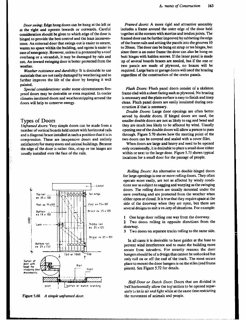
Door swing: Edge hung doors can be hung at the left or at the right and operate inwards or outwards. Careful consideration should be given to which edge of the door is hinged to provide the best control and the least inconven- ience. An external door that swings out is easier to secure, wastes no space within the building, and egress is easier in case of emergency. However, unless it is protected by a roof overhang or a verandah, it may be damaged by rain and sun. An inward swinging door is better protected from the weather.
Weather resistance and durability: It is desirable to use materials that are not easily damaged by weathering and to further improve the life of the door by keeping it well painted.
Special considerations: under some circumstances fire- proof doors may be desirable or even required. In cooler climates insulated doors and weatherstripping around the doors will help to conserve energy.
Types of Doors V$amed doors: Very simple doors can be made from a number of vertical boards held secure with horizontal rails and a diagonal brace installed in such a position that it is in compression. These are inexpensive doors and entirely satisfactory for many stores and animal buildings. Because the edge of the door is rather thin, strap or tee hinges are usually installed over the face of the rails.
Topratl __-- -- . - _- -- er 25 = loo
Post ex 75.10F l-lw7Tii
\ ’
I\\,‘4 II
I IIC.
Eq Tee hlnqr
Batten er 19x
Lock -- -Middle rail ex 25 x125.
Brace ex 25 x 100
Uetall of post wth bead for stopping dwr movements
Figure 5.68 A simple unframed door.
k% ments of Construction 163
Framed doors: A more rigid and attractive assembly includes a frame around the outer edge of the door held together at the comers with mortise and tendon joints. The framed door can be further improved by rabbeting the edge of the frame rails and setting the panels into the grooves 10 to 20mm. The door can be hung on strap or tee hinges, but since there is an outer frame the door can also be hung on butt hinges with hidden screws. If the inner panel is made up of several boards braces are needed, but if the one or two panels are made of plywood, no braces will be required. Large barn or garage doors will need the bracing regardless of the construction of the center panels.
FIush Doors: Flush panel doors consist of a skeleton frame clad with a sheet facing such as plywood. No bracing is necessary and the plain surface is easy to finish and keep clean. Flush panel doors are easily insulated during con- struction if that is necessary.
Double Doors: Large door openings are often better served by double doors. If hinged doors are used, the smaller double doors are not as likely to sag and bend and they are much less likely to be affected by wind. Usually opening one of the double doors will allow a person to pass through. Figure 5.70 shows how the meeting point of the two doors can be covered and sealed with a cover fillet.
When doors are large and heavy and need to be opened only occasionally, it is desirable to place a small door either within or next to the large door. Figure 5.7 1 shows typical locations for a small door for the passage of people.
Rolling Doors: An alternative to double-hinged doors for large openings is one or more rolling doors. They often operate more easily, are not as affected by windy condi- tions nor as subject to sagging and warping as the swinging doors. The rolling doors are usually mounted under the eave overhang and are protected from the weather when either open or closed. It is true that they require space at the side of the doorway when they are open, but there are several designs to suit avaiiety of situations. For example:
1 One large door rolling one way from the doorway. 2 Two doors rolling in opposite directions from the doorway. 3 Two doors on separate tracks rolling to the same side.
In all cases it is desirable to have guides at the base to prevent wind interference and to make the building more secure from intruders. For security reasons the door hangers should be of a design that cannot be unhooked but only roll on or off the end of the track. The most secure place to mount the door hangers is on the stiles (end frame pieces). See Figure 5.72 for details.
Half-Door or Dutch Door: Doors that are divided in half horizontally allow the top’section to be opened separ- ately !G let in air and light while at the same time restricting the movement of animals and people.
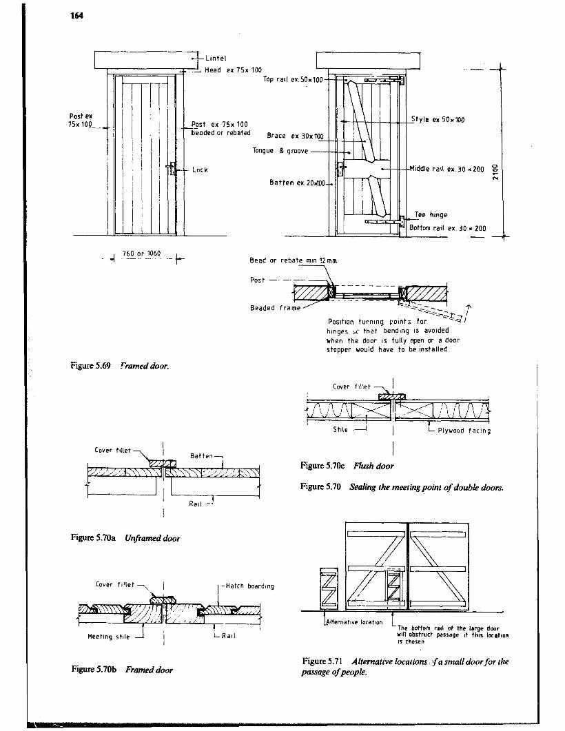
164
Lintel
- Head ex 75x 100
Too rail ex.50~100
Post ef 75x lO_o_
I ! I
I -
I I I 1 -
beaded or rebated
\
Lpck
Batten ex. 20~100
tyle ex 50~100
Middle rail ex. 30
.-
Read or rebate mm 12mm
Post --
Beaded fra
PositIon turnlnq points for
hrnges x that -bendIng IS avolded
when the door IS fully open or a door
stopper would have to be installed
Figure 5.69 -Framed door.
Cover fillet 7
I Stile -A 1 !- Plywood faclnb
Figure 5.70a Unframed door
Cover fillet 7 / rHatch boardlng
Meeting stde 1
Figure 5.70b Framed door
LRarl
I Figure 5.7oC Flwh door
Figure 5.70 Sealing the meetingpoint of double doors.
-B MIternatIve locatton
The bottom rail of the large door 14 obstruct passage of this laatlon IS chosen
Figure 5.7 1 Alternative locations fa small doorfor the paxsage of people.
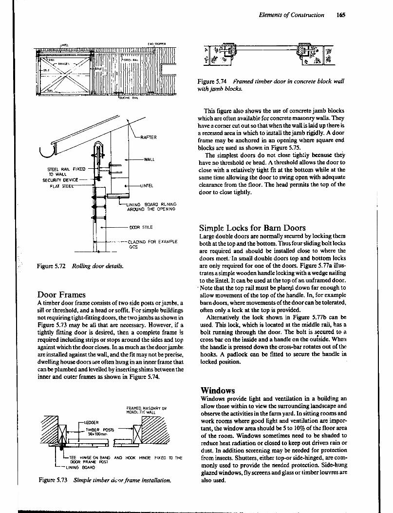
Elements of Construction 165
STEEL RAIL FIXED TU WALL
SECURITY DEVICE
LINING BOARD RLlNlNG AROUND THE OPENING
II I *+ WOR STILE
.-- CLADING FOR EXAMPLE GCS
--
Figure 5.72 Rolling door details.
Door Frames A timber door frame consists of two side posts or jambs, a sill or threshold, and a head or soffit. For simple buildings not requiring tight-fitting doors, the two jambs as shown in Figure 5.73 may be all that are necessary. However, if a tightly fitting door is desired, then a complete frame is required including strips or stops around the sides and top against which the door closes. In as much as the door jambs are installed against the wall, and the fit may not be precise, dwelling house doors are often hung in an inner frame that can be plumbed and levelled by inserting shims between the inner and outer frames as shown in Figure 5.74.
FRAMED. MASONRY OR MONOLITIC WALL
TIMBER WSTS
L LTEE HINGEON BAND AND 1+23~ HINGE FIXED m THE KCR FRAME POST
-LINING BOARD
Figure 5.73 Simple timber door frame instailation.
Figure 5.74 Framed timber door in concrete block wall with jamb blocks.
This figure also shows the use of concrete jamb blocks which are often available for concrete masonry walls. They have a comer cut out so that when the wall is laid up there is a recessed area in which to install the jamb rigidly. A door frame may be anchored in an opening where square end blocks are used as shown in Figure 5.75.
The simplest doors do not close tigh:iy because they have no threshold or head. A threshold allows the door to close with a relatively tight fit at the bottom while at the same time allowing the door to swing open with adequate clearance from the floor. The head permits the top of the door to close tightly.
Simple Locks for Barn Doors Largedouble doors are normally secured by locking them both at the top and the bottom, Thus four sliding bolt locks are required and should be installed close to where the doors meet.’ In small double doors top and bottom locks are only required for one of the doors. Figure 5.77a illus- trates a simple wooden handle locking with a wedge nailing to the lintel. It can be used at the top of an unframed door.
. Note that the top rail must be placed down far enough to allow movement of the top of the handle. In, for example barn doors, where movements of the door can be tolerated, often only a lock at the top is provided.
Alternatively the lock shown in Figure 5.77b can be used. This lock, which is located at the middle rail, has a bolt running through the door. The bolt is secured to a cross bar on the inside and a handle on the ouiside. When the handle is pressed down the cross-bar rotates out of the hooks. A padlock can be fitted to secure the handle in locked position.
Windows Windows provide light and ventilation in a building an allow those within to view the surrounding landscape and observe the activities in the farm yard. In sitting rooms and work rooms where good light and ventilation are impor- tant, the window area should be 5 to 10% of thz floor area of the room. Windows sometimes need to be shaded to reduce heat radiation or closed to keep out driven rain or dust. In addition screening may be needed for protection from insects. Shutters, either top-or side-hinged, are com- monly used to provide the needed protection. Side-hung glazed windows, fly screens and glass or limber louvres are also used.

166
Figure 5.75 Anchoring a door frame in a masonry wail without jamb blocks.
I -FRAMED WOR
RECTANGULAR TIMBER
Internal doors
DOOR
ll I II- FRAMED DOOR
min 50mm A,, i CORNER REINFORCED WITH
ANGLE IRON
SPLASH APRON
External doors
Figure 5.76 Types of thresholds.

Elements of Construction 167
L----- WALL CLADDING
SCREEN LINTEL WEDGE
-BOARDING
LEDGE ;l.+i WASHERS
---TIMBER HANDLE
r WEDGE
I
COVER FILLET
Figure 5.77a
Figure 5.77 Simple barn door lock.
Shutters: These are basically small doors and are con- structed as unframed, framed or flush shutters. Because of the smaller size only tare rails are required and the timber can be of smaller dimension. The principles of construction are the same as for doors. However, when the frame for the shutter is recessed in the wall,. the sill must be sloped and extend out from the wall to let the water drip clear of the face of the building. The window shutter can be side-hinged or top-hinged. A top-hinged shutter has the advantage of shading the opening when kept open as well as allowing ventilation while preventing rain from entering.
Glazed windows: Glazed windows are relatively expen- sive but are most practical in cold areas. When tempera- tures are low, the window can be shut while daylight still enters the room. Frames for glazed windows are available in wood and metal, the latter being more expensive. Glazed windows with frames are usually marketed as a unit, but Figure 5.81 illustrates various methods of frame construc- tion and installation.
Figure 5.77b
I5 Butt hinge +
FRAMED SHUTTER
Metal or timber
Figure 5.78 Recessed window or shutter.
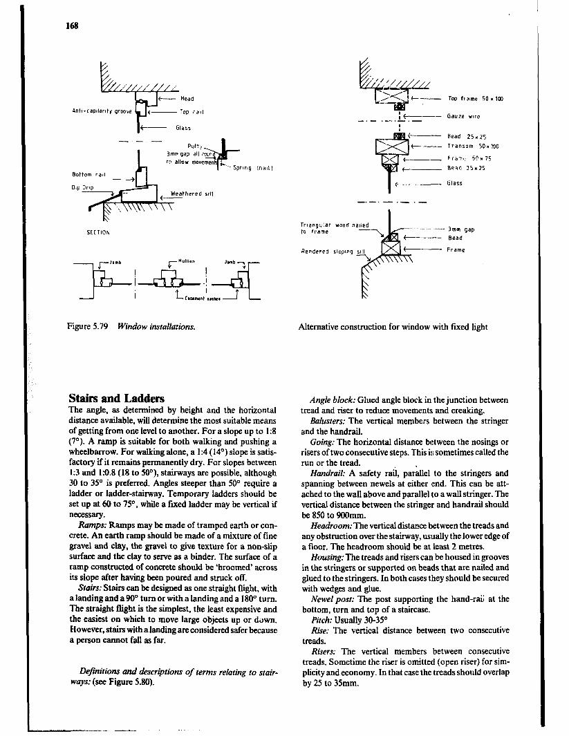
Bottom rail
SECTION
Figure 5.79 Window installations.
Stairs and Ladders The angle, as determined by height and the horizontal distance available, will determine the most suitable means of getting from one level to another. For a slope up to I:8 (7”). A ramp is suitable for both walking and pushing a wheelbarrow. For walking alone, a I:4 (14’) slope is satis- factory if it remains permanently dry. For slopes between I:3 and 1:O.S (18 to 509, stairways are possible, although 30 to 35’ is preferred. Angles steeper than 50” require a ladder or ladder-stairway. Temporary ladders should be set up at 60 to 75”, while a fixed ladder may be vertical if necessary.
Rumps: Ramps may be made of tramped earth or con- crete. An earth ramp should be made of a mixture of tine gravel and clay, the gravel to give texture for a non-slip surface and the clay to serve as a binder. The surface of a ramp constructed of concrete should be.‘broomed’ across its slope after having been poured and struck off.
Stairs: Stairs can be designed as one straight flight, with a landing and a 90” turn or with a landing and a 1 80° turn. The straight flight is the simplest, the least expensive and the easiest on which to move large objects up or down. However, stairs with a landing are considered safer because a person cannot fall as far.
Definitions and descriptions of terms relating to stair- ways: (see Figure 5.80).
Bead 25.25
Transom 50~ 100
PiaT,! 5n x75
Be?r! 25x25
Triangular wood naded to frame
Rendered sloping ~111
Alternative construction for window with fixed light
Angle block: Glued angle block in the junction between tread and riser to reduce movements and creaking.
Balusters: The vertical members between the stringer and the handrail.
Going: The horizontal distance between the nosings or risers of two consecutive steps. This is sometimes called the run or the tread.
Handrail: A safety rail, parallel to the stringers and spanning between newels at either end. This can be att- ached to the wall above and parallel to a wall stringer. The vertical distance between the stringer and handrail should be 850 to 900mm.
Headroom: The vertical distance between the treads and any obstruction over the stairway, usually the lower edge of a floor. The headroom should be at least 2 metres.
Housing: The treads and risers can be housed in grooves in the stringers or supported on beads that are nailed and glued to the stringers. In both cases they should be secured with wedges and glue.
Newel post: The post supporting the hand-rai; at the bottom, turn and top of a staircase.
Pitch: Usually 30-35O Rise: The vertical distance between two consecutive
treads. Risers: The vertical members between consecutive
treads. Sometime the riser is omitted (open riser) for sim- plicity and economy. In that case the treads should overlap by 25 to 35mm.

Elements of Construction 169
Steps: The combined treads and risers. Stringers: The inclined beams supporting the steps. The
strength required for the stringers will depend on the load and method of support. They may be supported only at the ends or continuously along the wall.
Treuds: The members stepped on as a person climbs the stairs. The treads must be strong enough to carry and transfer the imposed load to the stringers without excessive deflection. They should have a non-slippery surface. The treads can be housed in grooves in the stringers or sup- ported on beads that are nailed and glued to the stringers. In both cases they are secured with wedges nailed and glued to the stringer.
Width: Sufficient width for two persons to pass requires a width of 1.1 metre. A minimum width of 6OOmm can be used for traffic of persons not carrying anything.
Figure 5.80 Stairway construction.
The pitch for most stairs should not exceed 42’ nor be less than 30”, and for stairs in regular use a maximum of 35O is recommended. For most stairs a minimum going of 250mm and a maximum of 300mm should be adopted, although in domestic stairs a minimum of 200mm is accep- table for stairs that .- -e used infrequently. A rise from 150 to 220mm is usuahy satisfactory. Comfort in the use of stairs depends largely upon the relative dimensions of the rise and going of the steps. Rules for determining the proportion are based on the assumptions that about twice as much effort is required to ascend as to walk horizontally and that the pace of an average person measures about 585mm. Thus, the fact that a 300mm going with a rise of 14Omm or 150mm is generally accepted as comfortable, results in the rule that the going plus twice the rise should equal 580 to 600mm.
it is essential to keep the dimensions of the treads and risers constant throughout any flight of steps to reduce the risk of accidents caused by changing the rhythm of move- ment up or down the stairway.
Stairs are constructed by gluing and wedging the treads and risers into the housing grooves in the stringers to form a rigid unit as shown in Figure 5.80.
Stairs are designed to be either fixed to a wall with one outer stringer, fixed between walls, or freestanding, the
majority of stairways having one wall and one outer strin- ger. The wall stringer is fixed directly to the wall along its, entire length or is fued to timber battens plugged to the wall. The outer stringer is supported at both ends by the posts. The posts also serve as the termination point for handrails which span between them.
The space betw ‘en the handrail and the tread may be filled with balusters, balustrade or a solid pannel to improve both the safety and appearance of the stairway.
Reinforced concrete is better suited for outdoor stairs than is timber. The number, diametre and spacing of the main and distribution reinforcement must always be calcu- lated for each stairway by an experienced designer.
TREADIT x253-3OOmm. RISER(RI= lM-220mm.
Figure 5.8 1 Typicalformworkfor casting concrete stairs.
Ladder-stairway: The recommended pitch for this type of steep, narrow stairway is 60°. The width is usually about the minimum of 600mm. The size of the going (tread) is. dependent on the pitch. The values in table 5.17 are recommended:
Table 5.17 Measurements of Tread and Rtie at dyerent pitch of the stairway
Pitch degrees 50 55 60 65 70 75
* Tread, mm 220 190 160 130 100 70 Rise, mm 262 272 277 278 275 262
Timber ladders are basically of two types:
1 Those having round rungs fixed in holes in the strin- gers, and ,
2 Those having square or slightly rectangular treads cut and nailed in on the forward side of the stringers.
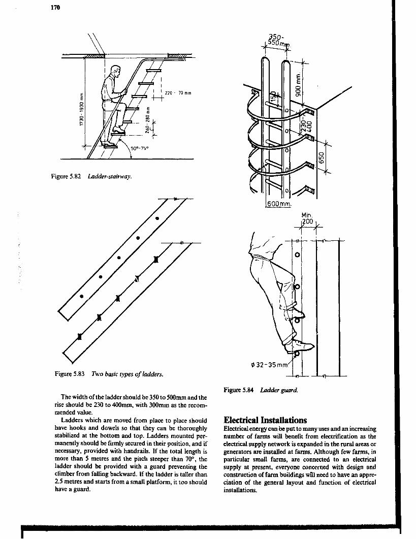
UP ’ ! \ ’ ’ 220 - 70mm
+-t-
Figure 5.82 Ladder-srairway.
Figure 5.83 Two basic rypes of ladders.
The width of the ladder should be 350 to 500mm and the rise should be 230 to 4OOmm. with 300mm as the recom- mended value.
Ladders which are moved from place to place should have hooks and dowels so that they can be thoroughly stabilized at the bottom and top. Ladders mounted per- manently should be firmly secured in their position, and if necessary, provided with handrails. If the total length is more than 5 metres and the pitch steeper than lo”, the ladder should be provided with a guard preventing the climber from falling backward. If the ladder is taller than 2.5 metres and starts from a small platform, it too should have a guard.
1600mm.
Min.
Figure 5.84 Ladder guard.
Electrical Installations Electrical energy can be put to many uses and an increasing number of farms will benefit from electrification as the electrical supply network is expanded in the rural areas or generators are installed at farms. Although few farms, in particular small farms, are connected to an electrical supply at present, everyone concerned with design and construction of farm buildings wTll need to have an appre- ciation of the general layout and function of electrical installations.
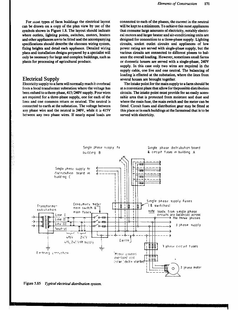
Elements of Construction 171
For most types of farm buildings the electrical layout can be drawn on a copy of the plan view by use of the symbols shown in Figure 1.8. The layout should indicate where outlets, lighting points, switches, motors, heaters and other appliances are to be fitted and the accompanying specifications should describe the choosen wiring system, fling heights and detail each appliance. Detailed wiring plans and installation designs prepared by a specialist will only be necessary for large and complex buildings, such as plants for processing of agricultural produce,
Electrical Supply Electricity supply to a farm will normally reach it overhead from a local transformer substation where the voltage has been redued to a three-phase, 415/24OV supply. Four wires are required for a three-phase supply, one for each of the lines and one common return or neutral. The neutral is connected to earth at the substation. The voltage between any phase wire and the neutral is 24OV, while it is 415V between any two phase wires. If nearly equal loads are
connected to each of the phases, the current in the neutral will be kept to a minimum. To achieve this most appliances that consume large amounts of electricity, notably electri- cal motors and larger heater and air-conditioning units are designed for connection to a three-phase supply. Lighting circuits, socket outlet circuits and appliances of low power rating are served with single-phase supply, but the various circuits are connected to different phases to bal- ance the overall loading. However, sometimes small farms or domestic houses are served with a single-phase, 24OV supply. In this case only two wires are required in the supply cable, one live and one neutral. The balancing of loading is effected at the substation, where the lines from several houses are brought together.
The intake point for the main supply to a farm should be at a convenient place that allow for thepossible distribution circuits. The intake point must provide for an easily acces- sable area that is protected from moisture and dust and where the main fuse, the main switch and the meter can be fitted. Circuit fuses and distribution gear may be fitted at this place or in each buildings at the farmstead that is to be served with electricity.
Single phase supply to
bulldIng B
Single phase dlstrubutlon board 8 circuit fuses in bulldIng A
Single phase supply to 3lstruSutlon board In bulldIng C
Consumers meter maln switch & Transiorrwr
suhstatlcn n@ loads from single phase circuits are balanced across
-~1 the three phases
supply fuses
3 phase supply
3 phaw clrcult tuses
‘Mctnr rontrrl cvrrloaf! c?il
ir,tar,‘delta starter)
phase motor
Figure 5.85 TypicaI electrical distribution system.
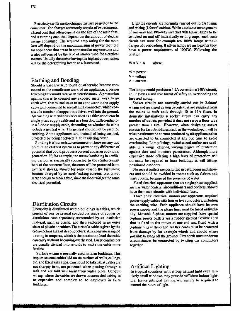
172
Electricity tariffs are the charges that are passed on to the consumer. The charges commonly consist of two elements, a fixed cost that often depend on the size of the main fuse, and a running cost that depend on the amount of electric energy consumed. The required amp rating for the main fuse will depend on the maximum sum of power required for appliances that are to be connected at any one time and is also influenced by the type of starter used for electrical motors. Usually the motor having the highest power rating will be the determining factor at a farmstead.
Earthing and Bonding Should a base live wire touch or otherwise become con- nected to the metalframe work of an appliance, a person touching this would receive an electric shock. A precaution against this is to connect any exposed metal work to an earth wire, that is lead as an extra conductor in the supply cable and connected to an earthing connector, which COD- sist of a number of copper rods driven well into the ground. An earthing wire will thus be carried as a third conductor in single phase supply cable and as a fourth or fifth conductor in a 3-phase supply cable, depending on whether the cable include a neutral wire. The neutral should not be used for earthing. Some appliances are, instead of being earthed, protected by being enclosed in an insulating cover.
Bonding is a low resistance connection between any two point of an earthed system as to prevent any difference of potential that could produce acurrent and is an additional protection. If, for example, the metal furnishing in a milk- ing parlour is electrically connected to the reinforcement bars of the concrete floor, the cows will be protected from electrical shocks, should for some reason the furnishing become charged by an earth-leaking current, that is not large enough to blow a fuse, since the Boor will get the same electrical potential.
Distribution Circuits Electricity is distributed within buildings in cables, which consist of one or several conductors made of copper or aluminium each separately surrounded by an insulative material, such as plastic, and then enclosed in an outer sheet of plastic or rubber. The size of a cable is given by the cross-section area of its conductors. All cables are assigned a rating in amperes, which is the maximum load the cable can carry without becoming overheated. Large conductors are usually divided into strands to make the cable more flexible.
Surface wiring is normally used in farm buildings. This implies sheeted cables laid on the surface of walls, ceilings, etc. and fured with clips. Care must be taken that cables are not sharply bent, are protected when passing through a wall and are laid well away from water pipes. Conduit wiring, where the cables are drawn in concealed tubing, is to expensive and complex to be employed in farm buildings.
Lighting circuits are normally carried out in SA fusing and wiring (1 .Omm* cables). While a suitable arrangement of one-way and two-way switches will allow lamps to be switched on and off individually or in groups, each such circuit can serve for example ten IOOW lamps without danger of overloading. If all ten lamps are on together they, have a power requirement of IOOOW. Following the relation:
W=VwA where:
W = power V = voltage A = current
The lamps would produce a 4.2A current in a 240V circuit, i.e. it leaves a suitable factor of safety to overloading the fuse arid wiring.
Socket circuits are normally carried out in 2.5mm2 wiring and arranged as ring circuits that are supplied from the mains at both ends through 10 to 15A fuses. In domestic installations a socket circuit can carry any number of outlets provided it does not serve a floor area greater than 1OOm’. However, when designing socket circuits for farm buildings, such as the workshop, it will be wise to estimate thecurrent produced by all appliances that are expected to be connected at any one time’to avoid overloading. Lamp fittings, switches and outlets are avail- able in a range, offering varying degree of protection against dust and moisture penetration. Although more expensive those offering a high level of protection will normally be required in farm buildings as will fittings positioned outdoors.
No socket outlets are permitted in bathrooms and show- ers and should be avoided in rooms such as clairies and wash rooms, because of the presence of water.
Fixed electrical apparatus that are single phase supplied, such as water heaters, airconditioners and cookers, should have their own circuits with individual fuses.
Three phase electrical motoss and apparatus required power supply cables with four or five conductors, including the earthing wire. Each appliance should have its own power supply and the phase lines must be fused individu- ally. Movable 3-phase motors are supplied f~cm special 3-phase power outlets via a rubber sheeted flexible c~;rd that is fixed to the motor at one end and fitted with a 3-phase plug at the other. All flex cords must be protected from damage by for example wheels and should where possible be hung off the ground. Flex cords must under no circumstances be connected by twisting the conductors together.
Artificial Lighting In tropical countries with strong natural light even rela- tively small windows may provide sufficient indoor light- ing. Hence artificial lighting will mainly be required to extend the hours of light.

Elements of Construction 173
The two most commonly used artificial light sources, where electrical energy is available, are in candescent bulbs and flourescent tube. Tubes and fittings for tubes are more expensive than bulbs and bulb fittings, but tubes produce three to five times as much light per unit of electric energy, Lave up to ten times as long life and have a lower heat production. Hence flourescent light normally is the chcap- est despite the higher initial cost. However, in small rooms where the light is switched on and off frequently bulb fittings are usually preferred as the installation cost in this case is more important than the energy cost. Merary vapour and sodium lamps are often used for outdoor lighting. They have higher efficiency in terms of light pro- duced than flourescent tubes, but their light covers only a limited spectrum and this tend to distort colours.
Various types of fittings are normally available for both bulbs and tubes. While a naked bulb or tube may be sufficient in some circumstances, fittings that protect the lamp from physical damage and moisture penetration will often be required in farm buildings. From an optical point of view thr fitting should obscure the lamp and present a larger surface area of lower brightness to reduce the glare caused by excessive luminance contrast. This is particu- larly important if the lamp is positioned where it will be directly viewed. A lighting point must also be positioned so that reT: -ted glare and trouble some shading of a work area is avoided. While light colours on interior surfaces will
create a bright room, shades of blue or green produce a feeling of coolness. The dusty conditions in many farm buildings implies the use of fittings that allow for easy cleaning. Accumulated dust can reduce the flow of light by more than 50%.
Most agricultural production operations carried out in buildings can be performed quite satisfactory using natural light, but where artificial light is to be installed the standard of illumination should be related to the activities cam ried out. While the installation of 2.0 to 3.OW flourescent light per square metre floor area will be sufficient for general illumination, work areas need more light, say 5 to 8 W/m*, and a desk or work bench where concentrated or exacting tasks are performed may need 10 to 15 W/m2 or more. Where bulbs are to be installed instead of tubes the above values will have to be at least trippled.
Electrical Motors Single phase motors in sizes up to about 1kW have a wide range of applications, particularly for use in domestic appliances. The most common type, the single phase series motor or universal motor, produce a good starting torque and can be run on both alternating current (AC) and direct current (DC). While it has the advantage of being able to be
- Plastic or porrelaln flttlng
--- Bulb
A u---- Glass or plastic opal globe obscuring lamp
Dctfused Ilgi-t emltted from larger surtace area than the bulb
w er Effectwe cooling but risk for glare
Elecfrlcal connectlons because of small !umlnous area
protected against dust 8 moisture
klourescent tube
Plistlc opal cover resultin? In dlttused
light emitted from larger surtace arp?
Single tube tlttlng Double tube tlttlng
Figure 5.88 Examples of Iightfittingsforfarm buildings.

174
connected to an ordinary socket outlek generally, it can not compete with the performance and efficiency of a 3-phase motor.
The 3-phase induction motor is the most common elec- trical motor at farms, where it is used to power fans, transport devises, mills, etc. Modem electrical motors are manufactured in a wide range of power ratings and types. Their enclosures range from screen protection to totally enclosed. Motors used in farm buildings normally should have an enclosure that is dust-tight and sprinkle-proof, i.e. it should not be damaged by being exposed to sprinkling of water from any direction. However, sometimes even better protection, such as dust-proof and flush-proof, is required and submersible motors must be totally enclosed and com- pletely water proof.
Inherent features of the induction motor are its poor starting torque and heavy starting current - up to six times the full load current. To prevent excessive voltage chop in
the supply hetwork and Electricity Company usually allow only small induction motors to be started direct on line. A star/delta starter is commonly fitted to motor above 2 to 3kW, and will reduce the starting current to about twice the full load current. Unfortunately it also reduces the already poor starting torque even further so that the motor can not start against heavy load. Other types of motors and starters are available for situation3 where starting against load can not be avoided, however.
The starter for any motor rated above about O.SkW must incorporate an overloadction that switches off should the current exceed a safe value for longer time than what is required to start the motor. In many installations it would, in addition, be desirable to include a release mechanism that prevent unexpected restarting after a power failure. A wide range of sensors, timers and other devises are availa- ble for automatic supervision and control of electric motor operation.
Further Reading Barnes M.M., Farm Construction, Buildings, Slough, Cement and Concrete Association, 197 1. Barry R., 7%e Construction of Buildings. Volume 14, London, Granada Publishing Ltd., 1969-1972. Burberry P., Environment and Services, Mitchell’s Build.,., inn Series, London, BT Batsford Ltd., 1979. Chudley R., Construction Technology, Volume l-3, London, Longmao Group Ltd., 1973-1976. Dancy H.K., A Manual of Building Construction, London, Intermediate Technology Publications Ltd., 1975. Foster J.S., Structure and Fabric. Part I, Mitchell’s Building Series, London, BT Batsford Ltd., 1979. Foster J.S., Harington R., Structure and Fabric, Part 2, Mitchell’s Building Series, London, BT Batsford Ltd., 1977. Fullerton R.L., Building Construction in Warm i’timates, Part l-3. Oxford, Oxford University Press, 1977-1579. German Appropriate Technology Exchange, Building Instructionsfor an Adobe Brick House, Munich, Germa;; Agency for
Technical Cooperation (GTZ), 1982. Haugum K., Construction of Farm Buildings, Nairobi, Housing Research and Developit:e:lt Unit, University of Nairobi,
1980. Janssen J.J.A., Bamboo, CICA publication 82.03, Eindhoven, Eindhoven University of Technology, 1982. King H., revised by Osboum D., Components, Mitchell’s Building series, London BT Batsford Ltd., 1979. Lippsmeier G., Tropenbau-Building in the Tropics, Munchen, Callwey Verlag, 1969. Longland F., Stem P. (ed), Field Engineering, And Introduction to Development Work and Construction in Rural Areas,
London. Intermediate Technology Publications Ltd., 1983. Ministry of Agriculture and Water Development, Grass 73atched Roofs, Lusaka, lMini& nf Agriculture and Water
Development, Engineering Section, 1984. Mukecji K., Whipple J.H., Escobar R.C., Roof Constructionsfor Housing in Developing Countries, Report on a Research
Study in Central America 1979, Eschborn, German Appropriate Technology Exchange, 1982. National Vocational Training Institute, Accra, Rural Building: 1. Reference Book, 2. Basic Knowledge, 2. Construction,
4. Orowing Book, Maastricht, Stichting Kongretatie F.I.C. Neidle M., Electrical Installation Technology, 3rd Ed., London, Butterworth & Co., Ltd., 1982. Noton N-H., Farm Buildings, Reading, College of Estate Management, 1982. Schreckenbach H., Abankwa J.G.K., Construction rechnology for a Developing Country, Eschborn, German Agency for
Technical Cooperation (GTZ), 1982. Sode O.J., Construction of Farm Buildings, Lusaka, Ministry of Agriculture and Water Development, Engineering Section,
1975. Whitaker J.H., Agricultural Buildings and Structures, Reston, Reston Publishing Co., 1979.

Chapter 6
Building Production
Building production is the organization and management of the plans, equipment, materials and labour involved in the construction of a building, while at the same time complying with all codes, rules and contractual stipula- tions. The procedure should be designed to run efficiently, to keep the costs low and to allow returns on the invest- ment to be realized as early as possible.
While many topics included in this chapter, such as standardization, organization of building works carried out by a contractor, tendering, contracting, inspectitin and control and progress charts may have limited relevance for small scale building projects on African farms, it is felt that an agricultural engineer will need some knowledge of these topics when faced with construction of communal and central facilities for agriculture and medium-to large-scale f‘arm buildings.
The costs of farm buildings such as animal housing and stores for produce can be expected to be repaid in terms of increased production, improved animal health, reduced storage losses, increased quality of produce and more effi- cient work performance. Other buildings such as dwellings are expected to be worth their costs mainly in terms of the standard of space, environment, convenience, construction and appearance they provide. The term “costs” in this context means costs over the whole life of the building, including operating and maintenance costs as well as an annual portion of the initial cost of construction, which in addition to building materials and construction iabour, includes fees paid to consultants, architects and legal advi- sors as well as capital interest and any loss of production incurred during the construction phase.
Building planning is thus concerned with economic building rather than with cheap building, i.e., with provid- ing the required standard of facilities at the lowest cost.
It should be pointed out that costs include not only cash payments but also the value of materials and work pro- vided by the farmer and his family since these are resources that could have been used for alternative activities at the farm to generate income or produce food. Most methods for construction- costing and economic feasibility studies imply that resources employed for the construction as well as the benefits of the finished structure can be valued in a convenient monetary unit. Subsistence farmers are part of the monetary economy to only a limited extent, thus it is difficult to put a fair price on material and work supplied by these farmers for construction at their farms or to correctly value the benefits of the structure.
There is a national interest in utilizing efficiently the resources invested in buildings. Governments express their minimum demands in the form of building regulations, codes and laws.
A farmer employing an agricultural engineer to design a building, a contractor to construct it and suppliers to deliver material will expect delivery of work and goods to
the standard and price agreed upon. For later reference it is common to specify the agreement in a contract, which makes reference to drawings and sp&if%ations for the structure and to general specifications. Inspections and controls are the means used to ensure tha& the agreement is followed.
The Building Production Process The building production commences when the farmer starts to seriously consider investing in a structure and does not end until the finished building is in use.
The process is divided into stages which follow in logical sequence. Each stage is terminated by a decision. Table 6.1 is an outline plan of work for the building production process. In small projects where the farmer performs virtu- ally all tasks involved, it may not be necessary to follow the chart in -&ail. Nevertheless the same procedural basics and logical order should be a goal. During the initial planning stages, the costs are low compared with the importance. The high costs involved in correcting errors once the site operations and construction are under way, can be avoided if time is spent working out a good, func- tional design which is technically and economically sound.
Methods of Construction The methods of constructing farm buildings refers to the way in which units and components of the building struc- ture are produced and assembled. The manner of organiz- ing this process differs from region to region and depends on the level of technology and the materials available. The operations involved in the construction of rural buildings of traditional designs are familiar to most rural people in Africa and small buildings on farms are usually con- structed by the farmers and their families. However, where new methods of construction, materials or layouts have been adopted, as well as where there is an increase in the size of the project, the assistance of trained artisans will usually be required. Self-help projects for the construction of communal facilities such as village stores must be accompanied by a training programme for the people involved.
Where most of the construction is done by employed building workers, three different contemporary building methods, which are described below, can be distinguished. While in the foreseeable future the traditional method of constructing farm buildings will remain the most common, the fact that an increasing number of industrialized build- ing products are being markeied has lead to the introduc- tion of post-traditional building and, to a limited extent, system building.

176
Table 6.1 Bicilding Roduclion Process
St-m SUb-ShgC Tasks to be done People diiy involved Result of work Decision to be reached
BIiCfiing Inception hwestig8te diimnt Client, Investment plan Choia of investment akematives for investments Agriculturnl economist. Tkvelopment plan alternative. and development of the various spaialists as Appoint Fnrm building fnrm now and in the future. requited for technical enginar. Alternatives to fmnna the brieting. investment. Suitability of conditions for diierent enterprises.
Feasibiity camy out studies of user Client, Feasible, alternative sets of Choia of,functionnl nnd requiaments, site conditions, Farm building engineer, functionid nnd technical technical requimmcnts.~ mquirements from autho- v8rious specialists as requirements with indication . ritics, functional and required for technical of theii cost. technical mquimmcnts and brieting. Cost
Sketch Outline Develop bnef further. Client, ,Altemntive rough sketches choia of general ouuine. PlnnS Proposals Roughly, sketch alternatives Farm building engineer for general outfines with AIL A for the general approach to various speci8lists 8s indication of their cost.
layout. functionnl planning. required to develop the design and construction. brief. Approach authorities.
Scheme Complete the brief. Client a&IlldtiVC. outline, Choia of constmctionnl Design Complete the functional Fnrm building enginar proposals for constructionnl design. Preliminmy decision
planning of the layout. design with indication of to produa the building. Preliminruy constructionnl of cost. Complete brief and design nnd cost calculation. functional layout. Obtain outline decision from authorities.
Sketch Standard Develop and complete the Client Alternative stnndnrd layouts. Choia of drawing set. Plans Drawings brief. Collect drawin@ from Farm building enginar Preliminary decision to Ah. B rclinble souras. Study the produa the building.
drawings and evaluate them regarding the ftmctionnl and technicat requiaments.
Brief should not be mod&J alter this point.
Fti Detail Full de,;ign of every part Farm buikliig engineer. Complete set of drawings, Final decision to produce the design Design nnd cc !mponent of the Assiitnna from specinlbt technical spsificatiom, building
buikiiig. Complete cost engineers might he required functional instructions and checking of designs. Final in large end complex an accurate cost estimate. decisions from authorities. Projects.
Any iurth:r change in location, size, shape or cost after time will resuh in abortive work.
working Production Pteparntion of final pro- Farm buildiigs engineer Production information. Detailed decision to carry out Drawings Information duction information i.e. Assistana from specinhst Time schedule work.
dntwings, schedules and might be required in huge specilications regarding and compkx projects. production methods and assembly nnd installation imtmctions. Papnre a time schedule for the production of the building
Purchase Biiof Preparation of bii of Farm building enginar Big of qunntity Select persons and firms to be Quantities quantity and tender docu- (sometimes spainlist Tender documents invited for tendering.
merits. assistana required).
Tender Evaluate and compare Client Contract with contractor Select contractor end Action tenders end quotations after Farm building enginar and suppliers suppliers. Contractor may
having put costs to Contractor contmct sub-contractors. exaptions nnd additions in the tenders end quotations. Draw up and sign contracts.
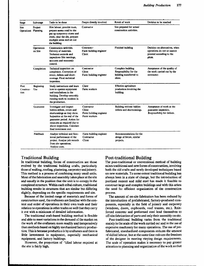
Building Production 177
stage sub-stage
Site Project operations Planning
T&s to be done People directly involved Result of work De&ion to be reached
Hire labour, provide tools, Contractor Site prepared for actual prepare aaxss road to site construction activities. put up temporary stores and sheds, clear the site, prepare stockpile areas and set out the building.
Operations on Site
Construction activities. fklivery of materials. Technical controls and inspections Site meet&i, accounts and aonomic control.
Contractor Fatm building engineer Client
Finished building Decision on alternatives, when operations do not or cannot proceed according to the phS.
Completion Technical inspection on Contractor Complete building Acceptance of the quality of completion. Correction of Client Responsibility for the the work carried out by the errors, defects and shott- Farm building engineer building transferred to contractor. co-. Final technical client. iIlSpCCtiOIL
Post Beginning construe- use tion
Study instructions and learn Client Effective agriculture how to operate equipment Farm workers production involving the and installations in the building. building. Develop smoothly running work to routines in the production.
investigate and inspect Contractor Building without hidden Acceptance of work at the hidden defects. errors and Client defects and shortcomings. guaranta inspection. shortcomings as they show. Farm building engineer Responsibility for defects. Inspection at the end of the Farm workers guarantee period. Action for measures as required due to above inspections. Calculate tinal investment cost.
Analyse technical and func- Fnrm building engineer Recommendations for the tional performance of the Contractor design of future, similar project. Analyse job records Client projects. from site operations~ Analyse costs.
Traditional Building In traditional building, fo&s of construction are those evolved by the traditional building crafts, particularly those of walling, roofing, plastering, carpentry and joinery. This method is a process of combining many small units. Most of the fabrication and assembly takes place at the site and usually in the position that the unit is to occupy in the completed structure. Within each tribal culture, traditional building results in structures that are similar but differing slightly, depending on the specific requirements and site.
Because of the limited range of materials and forms of construction used, the craftsmen are familiar with the con- tent and order of operations in their own trade and their relation to operations in other trades so well that they carry it out with a minimum of detailed information.
The traditional craft-based building method is flexible and able to meet variations in the demand of the market on the work of the craftsmen more readily and inexpensively than methods based on highly mechanized factory produc- tion. This is because production is by craftsmen and there is little investment in equipm&t, especially’ mechanical equipment, and factory buildings.
However, the proportion of -‘tilled labour required at the site is f&y high.
Post-traditional Building The post-traditional or conventional method of building mixes traditional and new forms of construction, involving both the old crafts and newly developed techniques based on new materials. To some extent traditional building has always been in a state of change, but the introduction of portland cement and mild steel has made it feasible to construct large and complex buildings and with this arises the need for efficient organization of the construction process.
The amount of on-site fabrication has been reduced by the introduction of prefabricated, factory-produced com- ponents, especially in the field of joinery and carpentry (windows, doors, cupboards, roof trusses, etc.). Rein- forced concrete and preformed steel lend themselves to off-site fabrication of parts and only their assembly on site.
Post-traditional building varies from the traditional mainly in the scale of the work carried ou: and in the use of expensive machinery for many operations. The use of pre- fabricated, standardized components reduces the amount of skilled labour, but at the same time redllces the freedom of the designer in meeting drying design requirements. The scale of operation makes it necessary to pay greater attention to planning and organization of the work so tha.t
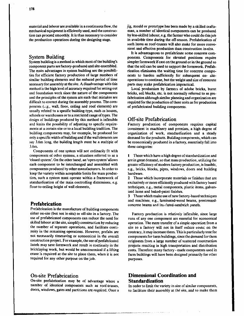
178
material and labour are available in a continuous flow, the mechanical equipment isefficiently used, and the construc- tion can proceed smoothly. It is thus necessary to consider the production operations during the designing stage.
System Building System building is a method in which most of the building’s component parts are factory-produced and site-assembled. The main advantages in system building are the possibili- ties for efficient factory production of large numbers of similar building elements and the reduced period of time necessary for assembly at the site. A disadvantage with this method is the high level of accuracy required for setting out and foundation work since the nature of the components and the principles of the system are such that mistakes are difficult to correct during the assembly process. The com- ponents (2.g.. wall, floor, ceiling and roof elements) are usually related to a specific building type, such as houses, schools or warehouses or to a restricted range of types. The design of buildings produced by this method is inflexible and limits the possibility of adjusting to specific require- ments at a certain site or to a local building tradition, The building components may, for example, be produced for only a specific width of building and ifthe wall elements are say 3.6m long, the building length must be a multiple of 3.6m.
Components of one system will not ordinarily fit with components of other systems, a situation referred to as a ‘closed system’. On the other hand, an&open system’allows each component to be interchanged and assembled with components produced by other manufacturers. In order to keep the variety within acceptable limits for mass produc- tion, such a system must operate within a framework of standardization of the main controlling dimensions, e.g. floor-toceiling height of wall elements,
Prefabrication Prefabrication is the manufacture of building components either on-site (but not in-situ) or off-site in a factory, The use of prefabricated components can reduce the need for skilled labour at the site, simplify construction by reducing the number of separate operations, and facilitate conti- nuity in the remaining operations. However, prefabs are not necessarily timesaving or economical in the overall construction project. For example, the use of prefabricated lintels may save formwork and result in continuity in the bricklaying work, but would be uneconomical if a lifting crane is required at the site to place them, when it is not required for any other purpose on the job.
On-site Prefabrication On-site prefabrication may be of advantage where a number of identical components such as roof-trusses, doors, windows, gates and partitions are required. Once a
jig, mould or prototype has been made by a skilled crafts- man, a number of identical components can be produced by less-skilled labour, e.g. the farmer who could do this job in available time during the off-season. Prefabrication of such items as roof-trusses will also make for more conve- nient and effective production than construction in-situ.
It is advantageous to prefabricate some concrete com- ponents. Components for elevated positions require simpler formwork if cast on the ground or in the ground so that the soil can be used to support the formwork. Prefab- rication eliminates the waiting time for concrete compo- nents to harden sufficiently for subsequent on- site- operations to continue, but the weight and size of concrete parts may make prefabrication impractical.
Local production by farmers of adobe bricks, burnt bricks, soil blocks, etc. is not normally referred to as pre- fabrication although similar planning and organization are required for the production of these units as for production of prefabricated building components.
Off-site Prefabrication Factory production of components requires capital investment in machinery and premises, a high degree of organization of work, standardization and a steady demand for the products. Building components, which can be economically produced in a factory, essentially fall into three categories:
1 Those which have a high degree of standardization and are ingreat demand, so that mass production, utilizing the greater efficiency of modem factory production, is feasible, e.g., bricks, blocks, pipes, windows, doors and building hardware. 2 Those which incorporate materials or finishes that are exclusively or more efficiently produced with factory based techniques, e.g., metal components, plastic items, galvan- ized items and baked-paint finishes. 3 Those which make use of new factory-based techniques and machines, e.g., laminated-wood beams, prestressed- concrete beams and inslilated-sandwich panels.
Factory production is relatively inflexible, since large runs of any one component are essential for economical operation. The mere transfer of a simple operation from a site to a factory will not in itself reduce costs; on the contrary, it may increase them. This is particularly true for components for farm buildings, since the demand for them originates from a large number of scattered construction projects resulting in high transportation and distribution costs. Therefore many factory - made components used in farm buildings will have been designed primarily for other purposes.
Dimensional Coordination and Standardization In order to limit the variety in size of similar components, to facilitate their assembly at the site, and to make them
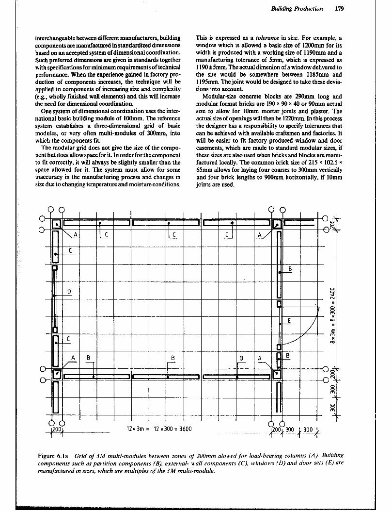
Building Production 179
interchangeable betweendifferent manufacturers, building components are manufactured in standardized dimensions based on an accepted system of dimensional coordination. Such preferred dimensions are given in standards together with specifications for minimum requirements of technical performance. When the experience gained in factory pro- duction of components increases, the technique will be applied to components of increasing size and complexity (e.g., wholly ftihed wall elements) and this will increase the need for dimensional coordination.
One system of dimensional coordination uses the inter- national basic building module of 1OOmm. The reference system establishes a threedimensional grid of basic modules, or very often multi-modules of 3OOnun, into which the components tit.
The modular grid does not give the size of the compo- nent but does allow space for it. In order for the component to fit correctly, it will always be slightly smaller than the space allowed for it. The system must allow for some inaccuracy in the manufacturing process and changes in size due to changing temperature and moisture conditions.
nn
This is expressed as a tolerance in sLe. For example, a window which is allowed a basic size of 1200mm for its width is produced with a working size of 119Omm and a manufacturing tolerance of 5mm, which is expressed as 1190 &5mm. The actual dimenion of a window delivered to the site would be somewhere between 1185mm and 1195mm. The joint would be designed to take these devia- tions into account.
Modular-size concrete blocks are 290mm long and modular format bricks are 190 r 90 x 40 or 90mm actual size to allow for IOmm mortar joints and plaster. The actual size of openings will then be 1220mm. In this process the designer has a responsibility to specify tolerances that can be achieved with available craftsmen and factories. It will be easier to fit factory produced window and door casements, which are made to standard modular sizes, if these sizes are also used when bricks and blocks are manu- factured locally. The common brick size of 215 x 102.5 x 65mm allows for laying four coarses to 300mm vertically and four brick lengths to 900mm horizontally, if 1Omm joints are used.
nn
Figure 6.la Grid of 3M multi-modules between zones of 200mm alowed for load-bearing columns (A). Building components such as partition components (B), external- wall components (C), windows (0) and door sets (E) are manrifoctured in sizes, which are multiples y/the 3 M multi-module.
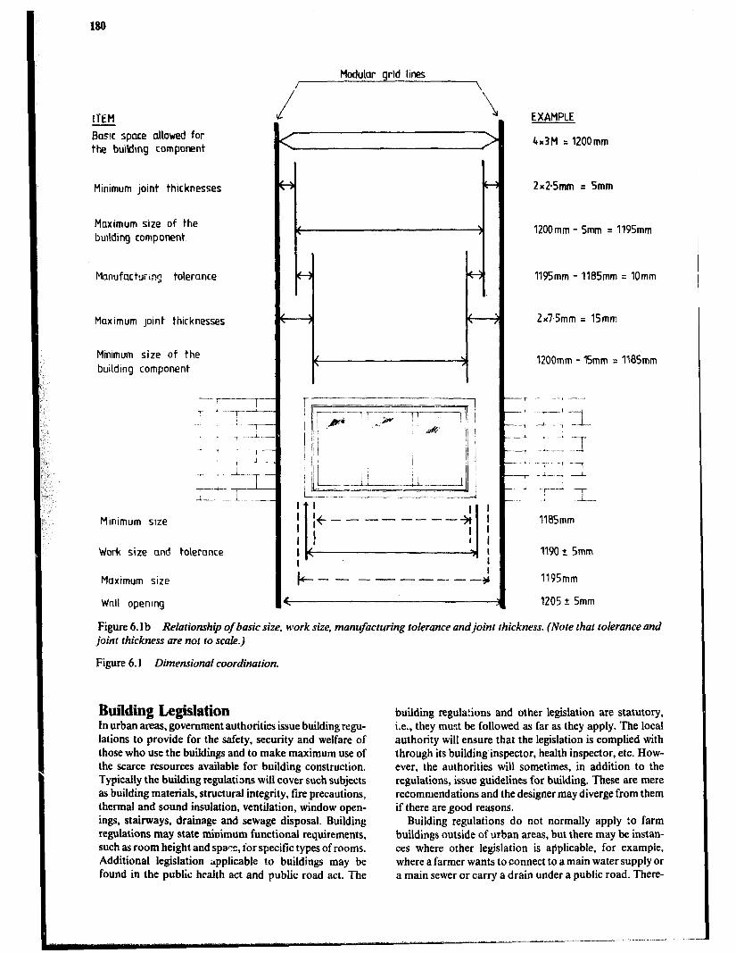
188
Modular grid lines /
/ \
\
ITEM
Bas!c space allowed for the buik!mg component
Minimum joint thicknesses
Maximum size of the bullding component
Manufacturq tolerance
Maximum Joint thicknesses
Minimum size of the buildmg component
Work size and toteronce
Maximum size 119Smm
Wnll openmg 1205 2 5mm
Figure 6.1 b Relationship of basic size, work size, manufacturing tolerance and joint thickness. (Note that tolerance and joid thickness are not to scale.)
Figure 6.1 Dimensional coordination.
EXAMPLE
4~3M = 1200mm
2x2.5mm = 5mm
1200mm - 5mm = 1195mm
1195mm - IlBSmm q IOmm
2xTSmm = 15mm
1200mm - ISmm = IlBSmm
1105mm
1190 +- Smm
Building Legislation In urban &as, government authorities issue building regu- lations to provide for the safety, security and welfare of those who use the buildings and to make maximum use of the scarce resources available for building construction. Typically the building regulations will cover such subjects as building materials, structural integrity, fire precautions, thermal and sound insulation, ventilation, window open- ings, stairways, drainage and sewage disposal. Building regulations may state minimum functional requirements, such as room height and spa?:, for specific types of rooms. Additional legislation ;rpplicable to buildings may be found in the public health act and public road act. The
building regulations and other legislation are statutory, i.e., they must be followed as far as they apply. The local authority will ensure that the legislation is complied with through its building inspector, health inspector, etc. How- ever, the authorities will sometimes, in addition to the regulations, issue guidelines for building. These are mere recommendations and the designer may diverge from them if there aregood reasons.
Building regulations do not normally apply !a farm buildings outside of urban areas, but there may be instan- ces where other legislation is applicable, for example, where a farmer wants to connect to a main water supply or a main sewer or carry a drain under a public road. There-
Building Production 181
fore it is wit !n contact the local authorities about any new building proposal or major alteration to an existing build- ing. If a local authority’s approval is necessary, copies of drawings and specifications will have to be submit(--! for its advice and approval.
Construction Costing Throughout the building production process costs will have a major influence when choosing from alternative designs. An excessively high cost may even cause the whole project to be abandoned. In the initial stages, when rough sketches are evaluated, general guideline costs based on building area or volume may be sufficient. In the final design stage, when the farmer has to decide whether or not to proceed with construction, a more detailed cost estimate based on a simplified bill of quantities is usually prepared. A contractor will need the most accurate cost estimate based on a bill of quantities, since his quotation should he low enough to be competitive, but still give him a profit. On large projects, the bill of quantities is also used to determine interim payments for work that has been completed.
Quantity Surveying The objective of quantity surveying is to provide an accu- rate bill of quantities, which is a list of the amounts of all materials and labour necessary to complete a construction project. In the simplified version, supplied by the designer with the final design documents, the labour requirement is not detailed. Enough accuracy for the purpose of this bill will be obtained by including labour as a lump sum, number of ho&s or day’s work or as a percentage cost of the building material cost. A bill of quantities for a stand- ard drawing often excludes such operations as site clear- ance, excavation and fffl, and external works, since such quantities may vary greatly from one site to another and therefore be difficult to assess accurately at the time the drawing is completed. Indeed, the bill for a standard draw- ing may be a mere list of materials, perhaps with a rough estimate of labour added.
To avoid mistakes or omission of any item, sophisticated methods have been developed for quantity surveying of large-scale projects. Farm buildings are normally smaller and far less complex and therefore a simplified procedure will be adequate. Many rules of thumb or conversions have been developed to take into account such factors as cutting waste, difference between nominal and actual size and breakage.
Taking-off The objective of taking-off is to produce a detailed list of all materials and work. Assessment of the quantities is made from detailed drawings and specifications of the project and done, as far as possible, in the order that the construc- tion of the building will proceed. First items are site clear- ing, excavation and foundation and fmal items are finishes
and external works. The dimensions of each item are obtained from the drawings and then the quantity is calcu- lated in the units in which it is customarily sold or priced. For example, excavation or fill, concrete, mortar and water would be in cubic metres, aggregates in cubic metres or tonnes, cement and lime in number of bags and many things such as bricks and blocks, windows and doors, building boards and roofing sheets in number of units. Sawn timber is listed in the number of pieces of specific sizes or where that is not necessary, total linear or volume quantities. Round timber will be in number of units of specific cross section and length.
A particular item which occurs in several places in a building, can be noted each time it occurs or the number of units can be totaled at one place. One way of obtaining completeness is to tick off each item on the drawing as it is listed.
Assessment of Labour Detailed iabour requirements to complete the type of con- struction commonly used in farm buildings may be difficult to find ‘in published sources. This is because the contrac- tors, who have the best knowledge of such data, use them as a means to compete for tenders. Also, most construction companies involved in farm building are too small to employ a quantity surveyor, who could collect the data. Data published by Quantity Surveyors’ or Building Con- tractors’ Associations tend to emphasize urban types of construction.
The rough estimates of the labour requirement needed’ by the designer of farm structures must be obtained through experience and by analyzing a number of projects similar to the one at hand. Where the farmer and the farm labourers construct a building, it is to he expected that the labour requirement will be higher than when skilled con- struction workers are used. However, the farm labour is available without any extra cash payment and may have few alternative uses during the off season.
Bill of Quantities The items for a bii of quantities are normally grouped together under headings for either the main operations (excavation, foundation, walling, flooring, rOOf StNCtUE, roofing, finishes, external works) or the trades involved (earth work, masonry, concrete work, carpentry and paint- ing). Work normally carried out by sub-contractors (wir- ing, plumbing, installation of equipment and furnishing) is listed separately.
The total quantity of each material or volume is trans- ferred from the taking-off sheets .o the appropriate head- ing in the bill of quantities, and while doing sU, a percen- tage allowance for waste and breakage, is normally added. The percentage added will depend on the type of material or volume, but is often taken to be 5 to 15%. To keep a record of the items, they should be ticked off on the taking- off sheets as they are transfered to the bill of quantities.
Labour may bc listed under each operatirJn or trade, but in the simplified bill, it is given as a lump sum at the end.
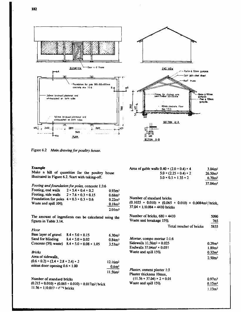
182
--- 260mm bnrkroll.phstered and whdernskd an both rxdes
, c Purl~n b Mmm gumpok?
Cow galv steel sheet
I I m A-A
PCTION B-B
Figure 6.2 Main drawing for poultry house.
Example Make a bill of quantities for the poultry house illustrated in Figure 6.2. Start with taking-off.
Footing andfoundation for poles, concrete 1:3:6 Footing, end walls 2 x 5.4 x 0.4 x 0.2 0.93m3 Footing, side wags 2 x 7.6 x 0.3 x 0.15 0.68mj Foundation for poles 4 x 0.3 x 0.3 x 0.6 0.22m3 Waste and spill 10% 0.18mr
2.Olm3
The amount of ingredients can be calculated using the figures in Table 3.14.
Floor Base layer of gravel 8.4 x 5.0 x 0.15 6.30m3 Sand for blinding 8.4 x 5.0 x 0.02 0.84mJ Concrete (5% waste) 8.4 x 5.0 x 0.08 x 1.05 3.53mr
&i&S
Area of sidewalls, (0.6 + 0.2) x (2.4 + 2.8 + 2.4) x 2 minus door opening 0.6 x 1 .OO
12.16m2 0.6mr
ll.S6m*
Number of standard bricks (0.215 + 0.010) x (0.065 + 0.010) = O.O17mr/brick 11.56 x l/O.017 = r”‘t bricks
Area of gable walls 0.40 x (2.0 + 0.4) x 4 5.0 x (2.25 + 0.4) x 2 5.0 x 0.5 x 1.35 x 2
3.84mr 26SOm2 6.7Omr
37.04mr
Number of standard bricks (0.1025 + 0.010) x (0.065 + 0.010) = O.O084m2/brick, 37.04 x l/O.084 = 4410 bricks
Number of bricks, 680 + 4410 Waste and breakage 15%
Total number of bricks
Mortar, compo mortar 1: I:6 Sidewalls 11.56m2 x 0.025 Endwalls 37.04mr x 0.05 1 Waste and spill 15%
Pfaster, cement plaster I:5 Plaster thickness IOmm,
(11.56 + 37.04) x 2 x 0.01 Waste and spill 15%
5090 765
5855
0.29mJ 1.89mr 0.32m-1
2.501113
0.97m3 O.lSm3
1.13mr
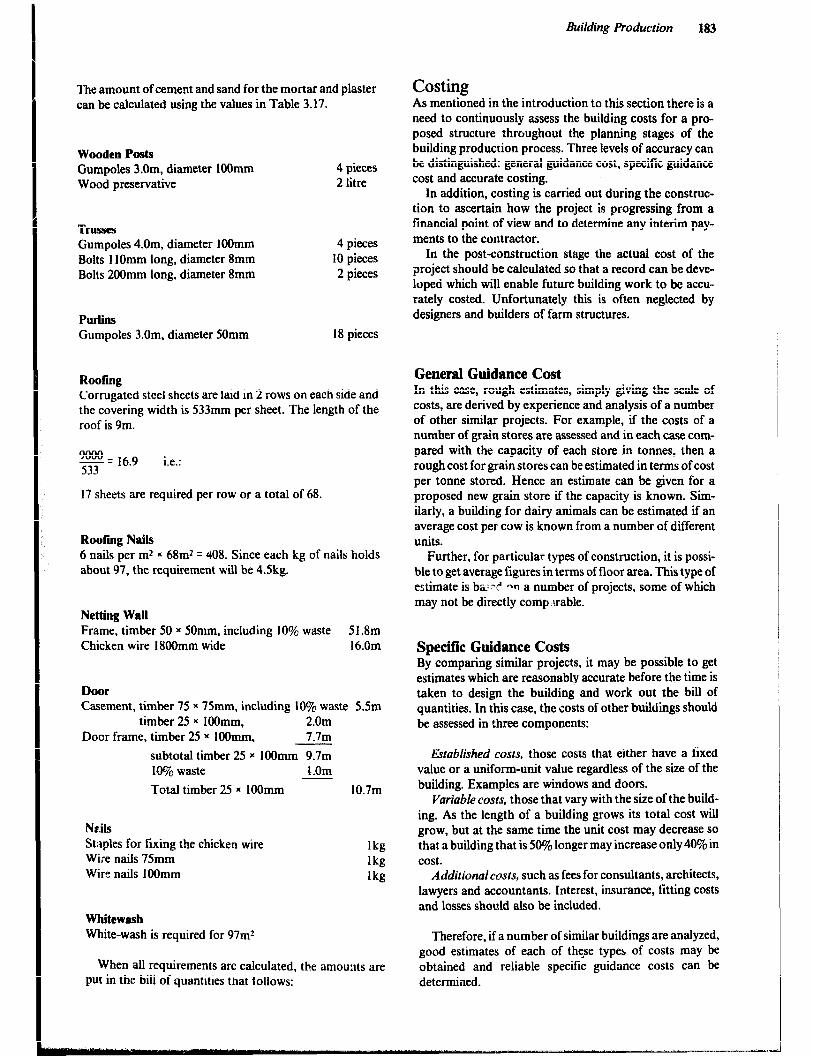
Building Production 183
The amount of cement and sand for the mortar and plaster can be calculated using the values in Table 3.17.
Wooden Posts Gumpoles 3.Om, diameter 109mm Wood preservative
4 pieces 2 litre
TrllSSS Gumpoles 4.0m, diameter 1OOmm Bolts 1lOmm long, diameter 8mm Bolts 200mm long, diameter 8mm
4 pieces 10 pieces 2 pieces
PUrlillS Gumpoles 3.0m. diameter SOmm 18 pieces
Roofiig Corrugated steel sheets are laid in 2 rows on each side and the covering width is 533mm per sheet. The length of the roof is 9m.
g = 16.9 i.e.:
17 sheets are required per row or a total of 68.
Rooting Nails 6 nails per rnz x 68m* q 408. Since each kg of nails holds about 97, the requirement will be 4.Skg.
Netting Wall Frame, timber SO x SOmm, including 10% waste 51.8m Chicken wire 18OOmm wide 16.0m
Door Casement, timber 75 x 7Smm, including 10% waste SSm
timber 25 x lOOmm, 2.0m Door frame, timber 25 x lOOnun, 7.7m
subtotal timber 25 x 1OOmm 9.7m 10% waste E.Om
Total timber 25 x 1OOmm 10.7m
NGlS Staples for fixing the chicken wire Wiie nails 7Smm Wire nails 1OOmm
lkg lb lb
Whitewash White-wash is required for 97m*
When all requirements arc calculated, the amou:tts are put in the bill of quantities that follows:
Costing As mentioned in the introduction to this section there is a need to continuously assess the building costs for a pro- posed structure throughout the planning stages of the building production process. Three levels of accuracy can be distinguished: general guidance cost, specific guidance cost and accurate costing.
In addition, costing is carried out during the construc- tion to ascertain how the project is progressing from a financial point of view and to determine any interim pay- ments to the contractor.
In the post-construction stage the actual cost of the project should be calculated so that a record can be deve- loped which will enable future building work to be accu- rately costed. Unfortunately this is often neglected by designers and builders of farm structures.
General Guidance Cost In this case, rough estimates, simply giving the scale of costs, are derived by experience and analysis of a number of other similar projects. For example, if the costs of a number of grain stores are assessed and in each case com- pared with the capacity of each store in tonnes, then a rough cost for grain stores can be estimated in terms of cost per tonne stored. Hence an estimate can be given for a proposed new grain store if the capacity is known, Sim- ilarly, a building for dairy animals can be estimated if an average cost per cow is known from a number of different units.
Further, for particular types of construction, it is possi- ble to get average figures in terms of floor area. This type of estimate is b&l,:? an a number of projects, some of which may not be directly comp.uable.
Specific Guidance Costs By comparing similar projects, it may be possible to get estimates which are reasonably accurate before the time is taken to design the building and work out the bill of quantities. In this case, the costs of other buildings should be assessed in three components:
Ektablished COSIS, those costs that either have a fixed value or a uniform-unit value regardless of the sire of the building. Examples are windows and doors.
Variable costs, those that vary with the size of the build- ing. As the length of a building grows its total cost will grow, but at the same time the unit cost may decrease so that a building that is 50% longer may increase only40% in cost.
Additionalcosts, such as fees for consultants, architects, lawyers and accountants. Interest, insurance, fitting Costs and losses should also be included.
Therefore, if a number of similar buildings are analyzed, good estimates of each of thge types of costs may be obtained and reliable specific guidance costs can be determined.
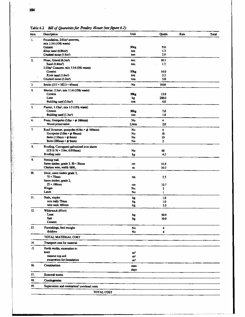
184
Table 6.2 will of Quantities for Pot&y Home fkefgwe 6.2)
Item Description Unit Quant. Rate Total
1. Foundation, 2.01ml amate, mix 1:3:6(1046vatc) tzmnat Mb 9.0
River sand (0.88m’) ton I.3
Cnuhed stone (1.8mJ) ton 2.9
2. Floor, Gravel (6.3mJ) ton 10.1
Sand (0.84m3) ton I.?
3.53m’ Concrete, mix l:3:6 (5% wasc) cement gkg 14.0 River sand (1.6mj) ton 2.3
crushed stone (32m’) ton 5.0
3. Bricks (215 * 1025 = 65mm) No 5910
4. Mortar, 25m’, mix Id:6 (1% waste) Cement Sobi 13.0 Lime kg 250.0 Building sand (2.8m3) ton $0
5. Plaster, 1.13m’. mix 15 (1% waste) Cement Ski3 7.0 Buikiii sand (1.3mJ) ton I.8
6. Posts, Gumpoks (3.Om = + ltmmm) No 4 WOOd QdW titles 2.0
7. Roof Structwv, gumpoks (4&n * 9 lOOmm) No 4 GumQolcs (3.Om If # 5onlm) No I8 Bolts (I IOmm s # Emm) No IO Bolts (2CHhnm * 0 8mm) No 2
8. Roofin& Corrugated @an&i iron sheets (CS E/76 x 2Om, O.Ol8mm) No 68
Roofm nails “8 4.5
9. NCttillgWilll Sawntimbcr.pdc3.50~5Omm ml 51.8 chicken wire, width MOO, m 16.0
10. Door, sawn timber pade 2, 75 x 75mm ml 5.5
sawn Iimhcr, grade 2, 25~lOOmm ml 10.7
Hinges No. 2 latch No I
II. NaiLS stapks kg 1.0 wknds75mm 1.0 WiNZli&lNhIUU 2 1.0
I2 Whitewah (97m*) limfi kB 50.0 salt k 10.0 crmcnt
13.
- 14.
3.
16.
17.
IS.
19.
Fumisbings, fad trouptrr, drinkcni
TOTAL MATERIAL COST
Transport cost for mated
-wd& cxcmaion to lcvcl
I’UllOWtOQsail
excavation for foudtion
Caarwtion
Extcn!. work5
contingarics
Supdsion and mntraaors’ovrrhtad costs
TOTAL COST
No No
ml ma ma
man
days
4 4

Building Production 185
Accurate Costing This is done in conjunction with the bill of quantities. By use of the rate column in the final bill of quantities together with the cost rate for each item, the accurate total cost of a job can be derived. This requires each individual item of material, volume or labour to be costed.
However, many building contractors will, for conven- ience and to facilitate the calculation of a quotation, derive a cost per quantity of common types of construction. For example, a cost per square metre of concrete block wall will include the cost of the blocks, labour to mix mortar, cost of mortar materials and labour required to lay the blocks. It may even incorporate a factor taking into consideration the average requirement of window and door openings and scaffolding.
To be able to do costing with this degree of detail how- ever, considerable information is needed which is gained from experience and data collected and analyzed over a number of building projects. The unit costs will have to be reviewed continuously or be corrected with an index for building costs.
Economic Feasibility In addition to the actual cost of constructing a building, which must be considered in relation to the financial capac- ity of the farmer, the total annual cost of the building should be determined. When the annual cost is then com- pared to the expected increase in income or the saving in storage costs, it forms the basis ior deciding whether or not the new building is a worthwhile investment, i.e., the eco- nomic feasibility of the building is determined.
To derive the true annual cost of a building, a number of factors must be considered. These include the estimated life of the building, annual repairs and maintenance, interest on the investment, insurance and in some countries real estate taxes. With the possible exception of repairs and maintenance, these are%xed”cost~ that occur whether the building is used or not. Consequently it is important to carefully plan the use of the building as well as the con- struction. The building may be thought of as a production cost and the potential income from the enterprise housed in it must be great enough to justify the cost of building. It must be stressed, however, that there may well be other than economic reasons for constructing a building. For instance, a dwelling cannot be justified in terms of profita- bility, but the amenity and welfare considerations may outweigh other factors.
Building I Se (Depreciation Period)
Physical Life All building components have a limited life. After a time materials will deteriorate to a point at which they can no longer fultill their function. Repair, replacement and main- tenance can extend the life, but eventually the overall deterioration becomes excessive.
The life span of a building is influenced by its design and construction. In general, more costly materials such as steel and concrete are likely to Last longer than timber and other organic materials. The physical life for agricultural build- ings may range from two to five years for the simplest structures and up to fifty years or more for the more substantial ones. An average figure may be between 10 and 20 years.
Economic Life Although a building may last for many years, it may cease to be economically sound at an earlier time for any of several reasons. It may be that the design has become obsolete and not suitable for new mechanization or per- haps it is too small because the farm has grown, or a new enterprise requiring a new layout or interior partitions and supports simply cannot be moved to accommodate the new requirements. General purpose buildings will there- fore have a longer economic life than those built for a specific enterprise.
Write-off Life It is impractical to expect any enterprise to pay the full cost of a new building in the first year after construction. There- fore the capital cost of the building is allocated or depre- ciated over several years. The number of years is dtter- mined by the write-off life, that is, the number oi:, xus over which it seems feasible to spread the original cost, but never fewer than the duration of a loan. The write-off life must also be no longer than the estimated physical or economic life to avoid the position of having a useless building for which the original cost has not yet been fully paid.
Economic conditions change rapidly and the risk of a large investment is reduced considerably ifthe depreciation can be taken over a relatively short write-off period. Ten years is considered short, 15 to 20 years medium and 20 to 30 years a long period. This means that a building i hat is still physically sound and economically practical afte. the depreciation has been completed can be considered an economic bonus for the farm.
For cost estimating, depreciation is usually taken on a “straight-line” basis, that is, equal annual amounts over the write-off life. The annual straight-line depreciation cost is the original cost of the building divided by the years of write-off life. There are a number of alternative methods for assessing depreciation, most of which result in greater costs in early years and decreasing costs over the life of the building.
Interest The cost of the money used to construct a building must be considered whether the financing is by means of a loan or by cash on hand. If money is borrowed, the interest cost is obvious. However, if the farmer invests his own money, he
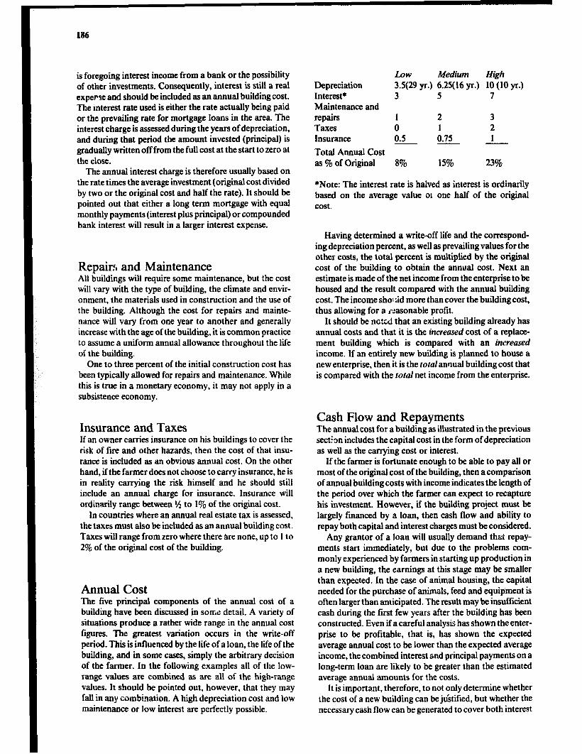
186
is foregoing interest income from a bank or the possibility of other investments. Consequently, interest is still a real expense and should be included as an annual building cost. The interest rate used is either the rate actually being paid or the prevailing rate for mortgage loans in the area. The interest charge is assessed during the years of depreciation, and during that period the amount invested (principal) is gradually written off from the full cost at the start to zero at the close.
The annual interest charge is therefore usually based on the rate times the average investment (original cost divided by two or the original cost and half the rate). It should be pointed out that either a long term mortgage with equal monthly payments (interest plus principal) or compounded bank interest will result in a larger interest expense.
Repairfi and Maintenance All buildings will require some maintenance, but the cost will vary with the type of building, the climate and envir- onment, the materials used in construction and the use of the building. Although the cost for repairs and mainte- nance will vary from one year to another and generally increase with the age of the building, it is common practice to assume a uniform annual allowance throughout the life of the building.
One to three percent of the initial construction cost has been typically aIlowed for repairs and maintenance. Whiie this is true in a monetary economy, it may not apply in a subsistence economy.
Insurance and Taxes If an owner carries insurance on his buildings to cover the risk of fire and other hazards, then the cost of that insu- rance is included as an obvious annual cost. On the other hand, if the farmer does not choose to carry insurance, he is in reality carrying the risk himself and he should still include an annual charge for insurance. Insurance will ordinarily range between iA to 1% of the original cost.
In countries where an annual real estate tax is assessed, the taxes must also be included as an annual building cost. Taxes will range from zero where there are none, up to I to 2% of the original cost of the building.
Annual Cost The five principal components of the annual cost of a building have been discussed in some detail. A variety of situations produce a rather wide range in the annual cost &ues. The greatest variation occurs in the write-off period. This is influenced by the life of a loan, the life of the building, and in some cases, simply the arbitrary decision of the farmer. In the following examples all of the low- range values are combined as are ah of the high-range values. It should be pointed out, however, that they may fall in any combination. A high depreciation cost and low maintenance or low interest are petfectly possible.
LOW Medium High Depreciation 3.5(29 yr.) 6.25( 16 yr.) 10 (10 yr.) Interest* 3 S 7 Maintenance and repairs 1 2 3 Taxes 0 1 2 Insurance 0.5 0.75 1
Total Annual Cost as % of Original 8% 15% 23%
*Note: The interest rate is halved as interest is ordinarily based on the average value ot one half of the original cost.
Having determined a write-off life and the correspond- ing depreciation percent, as well as prevailing values for the other costs, the total percent is multiplied by the original cost of the building to obtain the annu.al cost. Next an estimate is made of the net income from the enterprise to be housed and the result compared with the annual building cost. The income shol tid more than cover the building cost, thus allowing for a p:asonable profit.
It should be n&cd that an existing building already has annual costs and that it is the increased cost of a replace- ment building which is compared with an increased income. If an entirely new building is planned to house a new enterprise, then it is the rota1 annual building cost that is compared with the tofal net income from the enterprise.
Cash Flow and Repayments The annual cost for a building as illustrated in the previous section includes the capital cost in the form of depreciation as well as the carrying cost or interest.
If the farmer is fortunate enough to be able to pay all or most of the original cost of the building, then a comparison of annual building costs with income indicates the length of the period over which the farmer can expect to recapture his investment. However, if the building project must be largely financed by a loan, then cash flow and ability to repay both capital and interest charges must be considered.
Any grantor of a loan will usually demand that repay- ments start immediately, but due to the problems com- monly experienced by farmers in starting up production in a new building, the earnings at this stage may be smaller than expected. In the case of animal housing, the capital needed for the purchase of animals, feed and equipment is often larger than anticipated. The result may be insufficient cash during the first few years after the building has been constructed. Even if a careful analysis has shown the enter- prise to be profitable, chat is, has shown the expected average annual cost to be lower than the expected average income, the combined interest and principal payments on a long-term loan are likely to be greater than the estimated average annual amounts for the costs.
It is important, therefore, to not only determine whether the cost of a new building can be ju’stified, but whether the necessary cash flow can be generated to cover both interest

Building Production 187
and capital repayments. While thii is more of a business management problem than a farm structures prcbiem, it is no less important to the farmer contemplating a new building.
Organization for Small Building Constructions In the case of farm strucrclres,the future proprietor - the farmer - is not-n ally much more directly involved in any repair or construction process than would be the case with a building in an urban area. Although the farmer may appoint an advisor to help him with planning and design, employ a contractor or local craftsmen and take out a loan to finance the construction, his and his family’s participa- tion at all stages will normally be of great importance and serve to lower the amount of cash necessary for the project.
Depending upon the amount of self-involvement by the farmer, his family and any farm labour, and the way the construction is administered, four forms of organization can be distinguished: personal management, divided con- tract, general contract and turn-key contract.
Organization Forms Perscna 1 monogenwnt is a very common form of organiza- tion for repair work and construction of small- to medium- size farm buildings. The work is carried out by the employer (the farmer and his family) with the assistance of farm labourers and temporarily employed craftsmen. The employer may simply administer the work or he may also participate in the construction work himself.
Construction work
Figure 6.3 Personal management.
A divided contract implies that the employer engages different contractors for the construction work and for installation and fitting work. This form of organisation differs from personal management mainly in that the build- ing construction work is carried out on a contract. Self- involvement by the farmer can be arranged either by excluding some operations from the contract, such as earth work and external work, or by giving the farmer some form of “employee”status with the contractor. The latter is more easily arranged when current-account payment is used for the contract (see Section Forms of Payment). Building materials may be purchased by either the employer or the contractor. The contractor for the building construction work may be appointed to function as a coordinator for the various contracts.
Figure 6.4 Divided contract.
A general contract implies that the employer engages one contractor to carry out all of the building construction operations. The contractor may in turn engage sub- contractors to carry out work, such as fittings and installa- tions, which his firm lacks the skill or capacity to under- take. This form is uncommon for farm building construction, except for the largest projects.
A turn-key contract differs from the general contract in that the planning and design of the building is also included in the building contract. This form is very uncommon for farm building construction, except perhaps for completely prefabricated buildings in which the manufacturer serves as the contractor for erection.

188
Construction work
Figure 6.5 General contract.
Forms of Payment The contract or agreement between an employer and a contractor may state that the payment for the contracted work shall be made either at a fixed price, with or without installments forwork completed, or on a cost-plus basis to a ceiling figure, or with a running account for cost of materials purchased plus an agreement on labour costs.
A fixed price is common for general and turn-key con- tracts and often practiced with divided contracts. The advantage of a fixed price to the employer is that he will know at an early stage what the construction is going to cost. However, the contractor will require comprehensive documentation in the form of drawings and specifications to be able to give a qznation for a fixed-price contract.
Incomplete documentation will cause problems and fre- quent-negotiations to decide on details and variations usu- ally involving additional expenditure. Therefore the run- ning account is frequently practiced where the documenta- tion is insufficient or where it is difficult to make a satisfac- tory description of the work beforehand, as in the case of repair and maintenance work. If the running account is given a ceiling, the employer will be guaranteed a maxi- mum cost and will benefit, compared to a fMed price contract, should the work be less costly than the maximum expected.
Tendering The objective of tendering is to obtain proposals for con- struction work from different contractors and quotations for building materials from different suppliers. Their com- petition to present the most favorable offer should result in a less expensive building for the farmer.
Construction work
Figure 6.6 Turn-key conrract.
The Tender Procedure When the farmer has decided to proceed with the proposed structure, he and his advisors will prepare the tender documents, which usually consist of a letter of instructions, the necessary drawings and specifications and perhaps a bill of quantities, and send them to various contractors and suppliers.
A contractor, or his estimator, will cost all building materials, volumes and lahour and after adding an allo- wance for supervision, overhead, insurance, contingencies and profit, prepare a tender which is sent to the prospective, employer in a sealed envelope. During the preparation of the tender the contractor will visit the proposed building site to consider possible difficulties, in particular: access to the site and the necessity for temporary roads;‘storage of materials; type of ground; arrangements for siting any temporary office or welfare buildings; availability of labour in the area; arrangements for security of the work from theft and vandalism. He may also request further written documentation from the employer and, where sub- contractors are to be employed, obtain tenders for their work.
A supplier of building materials or equipment will require less documentation and usually will not have to visit the site in order to prepare a quotation. His offer may or may not include transport to the site.
When the period to reply as stated in the tender instruc- tion has expired, all the sealed envelopes containing the offers from the contractors and suppliers are opened. The contractors/ suppliers may be invited to attend the opening and be given names, prices and other relevant information contained in the offers. After careful evaluation of the offers the most favourable, which may not necessarily be the cheapest, is accepted and a contract is written.
Building Production 189
Methods of Tendering Open tendering. The prospective employer advertises in the press, giving brief details of the work, and issues an open invitation to contractors to apply for the necessary documents. The advertisement should state that the employer is free to select any or no bid that may be ten- dered. Tenderers are normally required to submit referen- ces and to pay a deposit for the documents which is returned on receipt of a serious tender. Open tendering is uncommon for farm construction work.
Selective tendering. Competitive tenders are obtained by drawing up a list of 3 to 5 serious contractors or suppli- ers in the area and inviting them to submit quotations. Normally the farmer and his advisor will know of a suffi- cient number of contractors who have the skill and expe- rience to construct farm buildings and are also known to have integrity. Hence the lowest tender cari usually be accepted.
Negotiated contracts are obtained by contacting one or two contractors or suppliers, who have been found satis- factory in the past. The price to carry out the work or deliver the material is negotiated until an agreement is reached. Negotiated contracts are also commonly used where the magnitude of the contract may be unknown at first, such as repair work, excavation in unknown ground or where the tender documents are insufficient. In these cases, the negotiation will normally aim at establishing reasonable task rates for a contract with a running account. With a fixed contract, a contractor would have to safe- guard himself against the unexpected and his large allo- wance for unforeseen expenditures would lead to a high contract price.
Evaluation of Tenders Quotations submitted to the prospective employer are likely to cornam reservations, exceptions, additions and other conditions for the work or delivery of materials. A contractor may also suggest an alternative design or build- ing method. If the letter of instructions for tender has stated that all such divergencies from the tender documents should be priced separately, it will be quite simple to recalculate the tenders so that they are comparable. In other cases they will have to be costed by the employer.
The letter of instruction will normally request the con- tractor to submit references from similar projects he has constructed in the past. For large projects, a bank reference and a performance bond are advisabie. These should be examined to establish the contractor’s practical and linan- cial ability to undertake the proposed work.
~ Contracts A contract is a legal document signed by both parties before witnesses. The essence of a contract for construction work is the promise of a contractor to erect the building as
shown on the drawings and in accordance with the detailed specifications in return for a specified amount of money known as the contract sun?. A variety of standard forms for building construction contracts are available, but it would be desirable to develop 3 standard contrat;t form specs- tally applicable to farm-%!ding construe tion.
If a bill of quantities is included in tht documents att- ached to the contract, the empiover will be responsible for any errors of measurement or shortcomings that occur in the bill. However, the selected contractor can be asked to control the bill and accept responsibility for it as being final. !n the case of contracts without a bill of quantities, the bill is prepared by the contractor and any errors arc: then his responsibility.
A standard contract form may include the following information, but each clause in it should be studied prior to signing and any clause that fails to meet the specific requirements of the project should be modified or deleted:
1 Names and addresses of employer and contractor. 2 List of all attached documents, i.e.,drawings, specifica- tions, and bill of quantities. 3 Amount of the contract sum. 4 Starting date and completion date. 5 Weekly penalty to be paid should the contractor fail to complete the work in time. (Not always included). 6 Directions for the employer to make a fair and reaso- nable extension of time for completion should the work be delayed through any cause beyond the control of the contractor. 7 Directions for the contractor to comply with all appli- cable rules and regulations issued by local authorities. 8 Directions for the contractor to arrange recurrent site meetings between the contractor and the employer and to keep a diary detailing progress of the work. (Not always applicable). 9 Directions for the contractor to obtain the employer’s approval before any work is executed involving variations from the drawings or specifications, in particular where the variations involve additional expenditure. 10 Reference to a list of any building materials and equipment that will be supplied by the employer. 11 The extent of the contractor’s responsibility for any liability, loss or claim arising in the course of or execution of the contract work, whether for personal injury or loss or damage to property. 12 Insurance requirements for the contractor. 13 Statement requiring the contractor to pay, at his own expense, for any defects or faults arising from materials or workmanship which are not in accordance with the draw- ings and specifications. 14 Statement requiring contractor to pay at his own expense for any hidden defects or faults which may appear during a specified guarantee period, usually 3 to 12 months, after the contract work has been completed. 15 Payment schedule, describing the percent of contract price to be paid at the completion of each step. 16 Guarantee amount. Normally about lo?& of the con- tract sum is withheld until the guarantee period has expired or all defects are corrected, whichever occurs last.
190
17 Procedure for resolving disputes ‘between the contrac- tor and employer, e.g., that it shall be referred to an arbitra- tor for a binding decision. 18 The signatures of the contractor, the employer and witnesses.
Specifications The specifications document supplements the drawings. The drawings should describe the geometry, location and relationships of the building elements to each other. The specifications set out quality standards for materials, com- ponents and workmanship that cannot be written on the drawings. For example, if the drawing states that concrete Type I should be used for a floor, the specifications may set out a mixing ratio, quality standards for aggregate and water, compaction and curing practices and quality stand- ards for joints and finish. Minimum requirements for capacity and reliability of equipment as well as calculations relating to design, insulation, ventilation, etc. may be included as appendices.
in small projects, typical of many farm structures, many of the specifications may be included on the drawings, but in large scale projects the specifications may run to many pages.
General Specification Since much of the information in the specifications will be similar from one project to another, it can be generalized to apply to most buildings. The building industry or govern- ment agencies in many countries have therefore developed a “General Specification for Building Works”. This nor- mally covers the majority of materials, types of construc- tion, fittings, furnishings, etc. for the types of buildings and other structures built in urban areas. While some of the information included may also be applicable to farm struc- tures, in general, a list of specifications will need to be developed for the particular structure.
The advantage in the use of a general specification is that all parties are expected to have access to a copy and that they are familiar with the quality standards required in the various sections. Apy planner/designer writing specifica- tions for a building may refer to the section numbers in the General Specification without repeating the text of those sections. In addition, particular specifications which sup- plement, amplify or amend the provisions of the General Specification will be required for each specific project.
To avoid confusion arising from discrepancies between the various building documents, the drawings will nor- mally prevail over the General Specification, particular specifications override both drawings and the General Specification and building code regulations will override all other documentation.
Occasionally when the government is the employer or when buildings are financed with government loans or subsidies, the General SpeciL&n is considered statu-- tory, but in all other cases its prdvisions can be used and amended as and when required.
Progress Chart A progress chart is a schedule, used to coordinate the sequence and timing of the operations in a building pro- duction process. It helps to ensure a timely supply of manpower, materials, equipment, machinery and sub- contracted services by providing information on what dates and in what quantities they will be required so that they can be ordered in good time. Furthermore it can be used to monitor the progress of the work and ensure that the schedule is being adhered to.
The chart is often divided into three parts:
The first part is produced by the farmer or his advisor and covers all work up to the time site operations start. It will include the sketching, any applications to authorities, final working drawings, tendering and ordering.
The second part is normally produced by the contractor and includes all site improvements and construction opera- tions. Figure 6.3.
The third part covers the starting up of production in the building and would be developed by the farmer and his advisors.
The preparation of a progress chart starts with listing all operations and their expected duration, and identifying operations which must follow each other in sequence.
In the second step achart is developed showing the input of labour, machinery and equipment for various opera- tions until the completion date is met. While doing this it will be no;iced that there is a sequence of operations called critical operations which must follow each other in a spe- cific order and which together determine the total time required to carry out the work.
In the third step, the requirements of resources, in par- ticular that of labour but also machinery, are adjusted so that a fairly uniform work force can be maintained. This is done by amending the timing and sequence of operations that can take place partly or wholly at the same time as the critical operations.
The fourth step consists of following the work, in partic- ular the critical operations, and revising the progress chart as problems or delays arise, e.g., delayed replies from authorities, contractors or suppliers, delayed delivery of materials and sub-contracted services, delay of the site operations due to prolonged bad weather.
Inspection and Control Whenever a building is constructed, it is likely that faults and defects will occur due to such things as deficiencies in the building materials, negligence by workmen and mis- takes in the drawings and specifications. Occasionally a contractor may be tempted to increase his profit by know- ingly producing inferior work. To avoid this as far as possible, the employer or a person experienced in building construction appointed by him, will function as an inspec- tor during the site operations.
Control is normally carried out continuously as the construction work proceeds. In addition, more formal
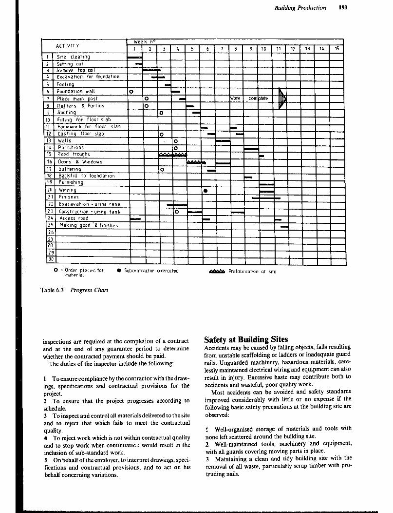
Building Production
2 Settmg out
3 Remove top sol1
4 Excavatton for foundatmn
I 1 nnst I I I IWwk I I lthi
I I I I i
I16 1 Doors Wmdows I
i i I
0 = Order piaced to1 material
l Subcontractor cmrracted
Table 6.3 Progress Chart
inspections are required at the completion of a contract and at the end of any guarantee period to determine whether the contracted payment should be paid.
The duties of the inspector include the following:
1 To ensure compliance by the contractor with the draw- ings, specifications and contractual provisions for the project. 2 To ensure that the project progresses according to schedule. 3 To inspect and control all materials delivered to the site and to reject that which fails to meet the contractual quality. 4 To reject work which is not within contractual quality and to stop work when continuatic;: would result in the inclusion of sub-standard work. 5 On ‘behalf of the employer, to interpret drawings, speci- fications and contractual provisions, and to act on his behalf concerning variations.
PpMp Prefabrlcatlon at site
Safety at Building Sites Accidents may be caused by falling objects, falls resulting from unstable scaffolding or ladders or inadequate guard rails. Unguarded machinery, hazardous materials, care- lessly maintained electrical wiring and equipment can also result in injury. Excessive haste may contribute both to accidents and wasteful, poor quality work.
Most accidents can be avoided and safety standards improved considerably with little or no expense if the following basic safety precautions at the building site are observed:
! Well-organised storage of materials and tools with none left scattered around the building site. 2 Well-maintained tools, machinery and equipment, with all guards covering moving parts in place. 3 Maintaining a clean and tidy building site with the removal of all waste, particulaily.scrap timber with pro- truding nails.

192
4 Making sure that all operators have been carefully instructed in the use of machinery and the handling of hazardous materials. 5 Insisting that all workers wear suitable clothing and protective gear, such as hard hats, hard-toe shoes and satety glasses. 6 Using properly designed, supported and braced scaf- folds, ladders and yiatforms. 7 Establishing and enforcing rules as to where people can work while elevated members are being installed. 8 Making sure that all temporary wiring and electrical equipment is kept well maintained and grounded and is properly used. 9 Having a good safety programme. Making workers aware of hazards and how to avoid accidents. 10 Maintaining suitable first aid equipment and supplies and making sure workers know how to use them can minimize the effects of any accidents that do happen.
Building Maintenance i!uildings deteriorate due to age, weathering and use. This
necessitates maintenance and repair to allow the building to retain its appearance and serviceable condition.
Cleaning, repainting, reroofing and replacing or repair- ing broken parts such as window panes, roof tiles, etc. help to maintain the original value of the building.
Maintenance costs can be kept down by using materials suitable for the climatic conditions and with which local builders are accustomed to working. Furthermore, the building should be simple in detail, have easily replaceable parts and be free of unnecessarily complex or sensitive technical installations.
The fabric of a building should bethoroughly inspected once or twice a year to assess the performance of different elements of the building. The inspection wilI result in a list of repair and maintenance jobs which should be carried out promptly, since insufficient or delayed measures will result in accelerated deterioration. The maintenance work is usu- ally carried out by the farmer himself, but in the case of largt repairs it may be done by hired building workers or a contractor. When a contractor is engaged, payment is often made on the basis of time and materials used accord- ing to an agreed schedule of prices.
Further Reading Fullerton, R.L. Building Construction in Worm Climates, Part 2, Oxford, Oxford University Press, 1978. Miles, D. A Manual on Building Maintenance. Volume 1 : Management; Volume 2 : Methods, London, Intermediate
Technology Publications, Ltd. 1976. Miles, D. Accounting and Bookkeeping for the Small Building Contractor, London, Intermediate Technologv Publica-
tions, Ltd., 1978. Miles, D. Financial Planning for the Small Building Contractor, London, Intermediate Technology Publications, Ltd.,
1979. Miles, D. The Small Building Contractor and the Client, London, Intermediate Technology Publications, Ltd., 1980. Seeley, I.H. Building Quantities Explained, (3rd ed.), London, The Maxmillian Press Ltd., 1979. Willis, A.J. and George, W.N.B. 7he Architect in Pructice, (6th ed.), London, Granada Publishing Ltd., 1981. Willis, A.J. and Willis, C.J. Prurticeand Procedurefor the Quantity Surveyor, (8th ed.), London, Granada Publishing Ltd.,
1980.

Chapter 7
Climate and Environmental Control
Introduction The quality of the environment in agricultural buildings includes such factors as temperature, light, moisture, air quality and movement, dust, odours, and disease agents. Environment affects animal comfort and health and ulti- mately production. It also influences the quality and lon- gevity of stored products. From an engineering standpoint, environment can be closely controlled. However, eco- nomic factors often limit the extent to which control can be justified.
The particular region of the nation and the resulting climatic zone will influence the manner in which environ- mental requirements are met. A humid area may require homes with open construction to provide continual venti- lation for comfort, whereas an arid region may need build- ings of great thermal capacity to protect against daytime heat, and night chill.
As a general rule Tropical Climates are found within the tropics. However, the influence of the climate on structures makes the techniques used applicable to many regions outside the tropics, e.g. the middle east.
The following brief discussion of Africa’s climatic zones is general and can be found worldwide in the tropics. It illustrates the wide variety of situations with which engi- neers are faced in designing environmentally suitable build- ings for people, animals and products.
Climatic Zones There are several climatic zones on the African Continent with widely varying characteristics.
1 Low-latitude, wet equatorial: High rainfall, humid and close to 27°C mean temperature throughout the year. Congo Basin. 2 Monsoon and Trade-wind bittoral: Climate dominated by trade-winds. Maximum rain in high sun season; min- imum following low sun season. Intense showers in eastern coastal zone. Warm throughout the year. Central and Western Africa and East Coast. 3 Wetdry tropical: Typified by very wet high sun season and very dry low sun season. West and Southern Africa. 4 Dry tropical: Characterized by extreme heat at high sun season and cool at low sun periods. Gradually changes from arid to semi-arid and into wet-dry tropical zone: Sahara, South Africa. 5 Dry subtropical: A north-south extension of the dry tropical zone. Greater annual temperature range: North and South Africa. 6 Altitude modified wet-dry tropical: Increases in alti- tude generally result in an increase in precipitation and a reduction in mean temperatures. Precipitation is seasonal and varies from 500 to 15OOmm depending on local condi- tions. Inland East and South-east Africa.
Climate can also vary greatly over relatively small areas, in particular where the country is hilly.
For design purposes, local climatic data from a nearby meteorological station should be obtained if possible.
A thorough knowledge of heat transfer, air-moisture- temperature relationships and ventilation, combined with a knowledge of climatic conditions and the environmental requirements of animals and Il’arm products, enables the engineer to design the best possible systems within eco- nomic constraints. Fo’r example, the maximum control reasonable for a cattle herd might be some artificial shade, whereas a high value fruit crop might justify the expense of a refrigerated storage.
Heat Terminology Heat is a form of energy. The molecules of a body are in constant motion and possess kinetic energy referred to as heat.
Temperature is intensity of heat i.e., the velocity of the molecules. In the SI-system it is measured in degrees Celsius (centigrade) or Kelvin (absolute).
Ambient temperature is the temperature of the medium surrounding a body, e.g., air temperature within a building.
Quantity of heat is measured in Joules.‘One calorie of heat will raise one gram of water 1’ Kelvin. This equals 4.187 Joules.
Sensible heot is the heat that causes a temperature change when there is a heat transfer, e.g., heat moving through the walls of a home causing a temperature rise.
Latent heat is the heat that causes a change in state but no change in temperature, e.g., heat that is absorbed when ice changes to water or when boiling water changes to vapor. However, water will evaporate to vapour over a wide range of temperatures. When air moves across the surface of water, some of the air’s sensible heat is converted to latent heat causing the air temperature to drop. The latent heat of vaporization changes with temperature:
OC
0 30
100
kJjkg
2500 2430 2256
Thermal capacity is tile ability of a material to absorb and hold heat. It is measured in J/(kg.“K). The thermal capacity of water is 4.187 kJ/(kg.O K) or 4.187 J/(g.“ K).
Spec$c heat is the dimensionless ratio between the thermal capacity of a material to that of water. However the actual thermal capacity measured in J/ (kg.O K) is often listed as specific heat.
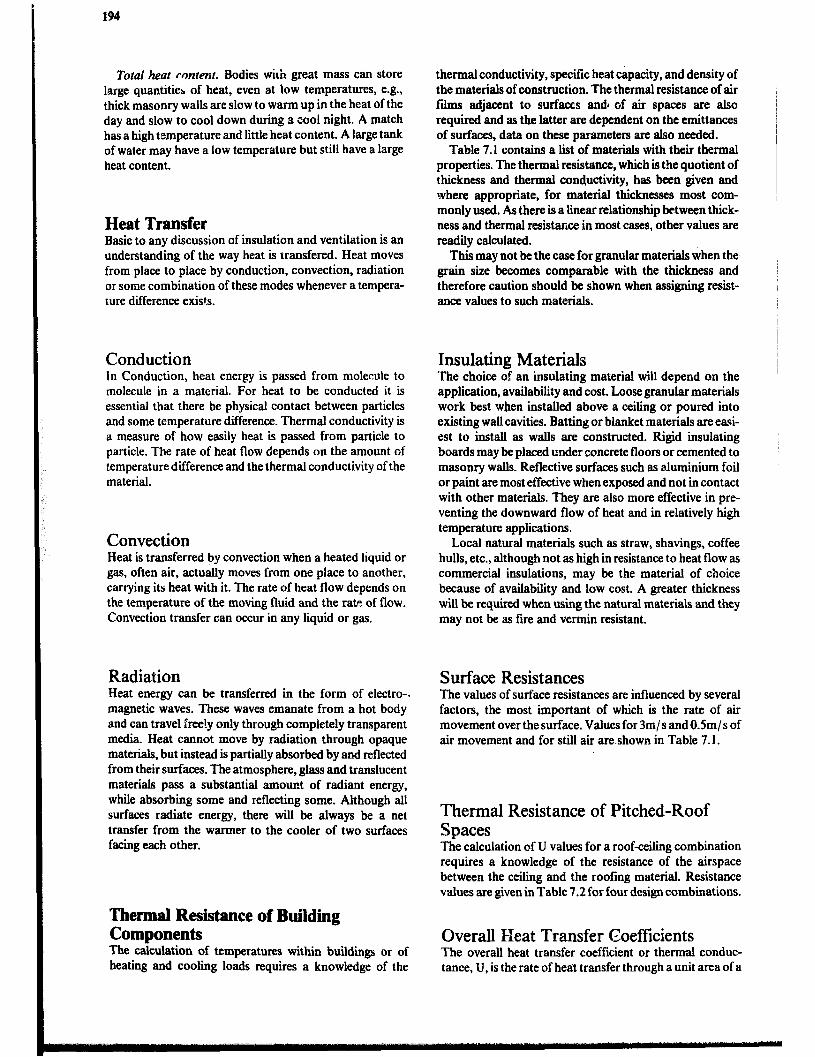
194
Total heat mntent. Bodies with great mass can store large quantities of heat, even at low temperatures, e.g., thick masonry walls are slow to warm up in the heat of the day and slow to cool down during a cool night. A match has a high temperature and little heat content. A large tank of water may have a low temperature but still have a large heat content.
Heat Transfer Basic to any discussion of insulation and ventilation is an understanding of the way heat is transfered. Heat moves from place to place by conduction, convection, radiation or some combination of these modes whenever a tempera- ture difference exists.
Conduction In Conduction, heat energy is passed from molecule to molecule in a material. For heat to be conducted it is essential that there be physical contact between particles and some temperature difference. Thermal conductivity is a measure of how easily heat is passed from particle to particle. The rate of heat flow depends on the amount of temperature difference and the thermal conductivity of the material.
Convection Heat is transferred by convection when a heated liquid or gas, often air, actually moves from one place to another, carrying its heat with it. The rate of heat flow depends on the temperature of the moving fluid and the rate of flow. Convection transfer can occur in any liquid or gas.
Radiation Heat energy can be transferred in the form of electro- magnetic waves. These waves emanate from a hot body and can travel free!y only through compietely transparent media. Heat cannot move by radiation through opaque materials, but instead is partially absorbed by and reflected from their surfaces. The atmosphere, glass and translucent materials pass a substantial amount of radiant energy, while absorbing some and reflecting some. Although all surfaces radiate energy, there will be always be a net transfer from the warmer to the cooler of two surfaces facing each other.
Thermal Resistance of Building Components The calculation of temperatures within buildings or of heating and cooling loads requires a knowledge of the
thermal conductivity, specific heat capacity, and density of the materials of construction. The thermal resistance of air films adjacent to surfaces andl of air spaces are also required and as the latter are dependent on the emittances of surfaces, data on these parameters arc also needed.
Table 7.1 contains a list of materials with their thermal properties. The thermal resistance, which is the quotient of thickness and thermal conductivity, has been given and where appropriate, for material thicknesses most com- monly used. As there is a linear relationship between thick- ness and thermal resistance in most cases, other values are readily calculated.
This may not be the case for granular materials when the, gram size becomes comparable with the thickness and therefore caution should be shown when assigning resist- ance values to such materials.
Insulating Materials The choice of an insulating material will depend on the application, availability and cost. Loose granular materials work best when installed above a ceiling or poured into existing wall cavities. Batting or blanket materials are easi- est to install as walls are constructed. Rigid insulating boards may be placed under concrete floors or cemented to masonry walls. Reflective surfaces such as ah.tminium foil or paint are most effective when exposed and not in contact with other materials. They are also more effective in pre- venting the downward flow of heat and in relatively high temperature applications.
Local natural materials such as straw, shavings, coffee hulls, etc., although not as high in resistance to heat flow as commercial insulations, may be the material of choice because of availabiity and low cost. A greater thickness will be required when using the natural materials and they may not be as fire and vermin resistant.
Surface Resistances The values of surface resistances are influenced by several factors, the most important of which is the rate of air movement over the surface. Values for 3m/s and 0.5m/s of air movement and for still air amshown in Table 7.1.
Thermal Resistance of Pitched-Roof Spaces The calculation of U values for a roof-ceiling combination requires a knowledge of the resistance of the airspace between the ceiling and the roofing material. Resistance values are given in Table 7.2 for four design combinations.
Overall Heat Transfer Coefficients The overall heat transfer coefficient or thermal conduc- tance, U, is the rate of heat transfer through a unit area of a
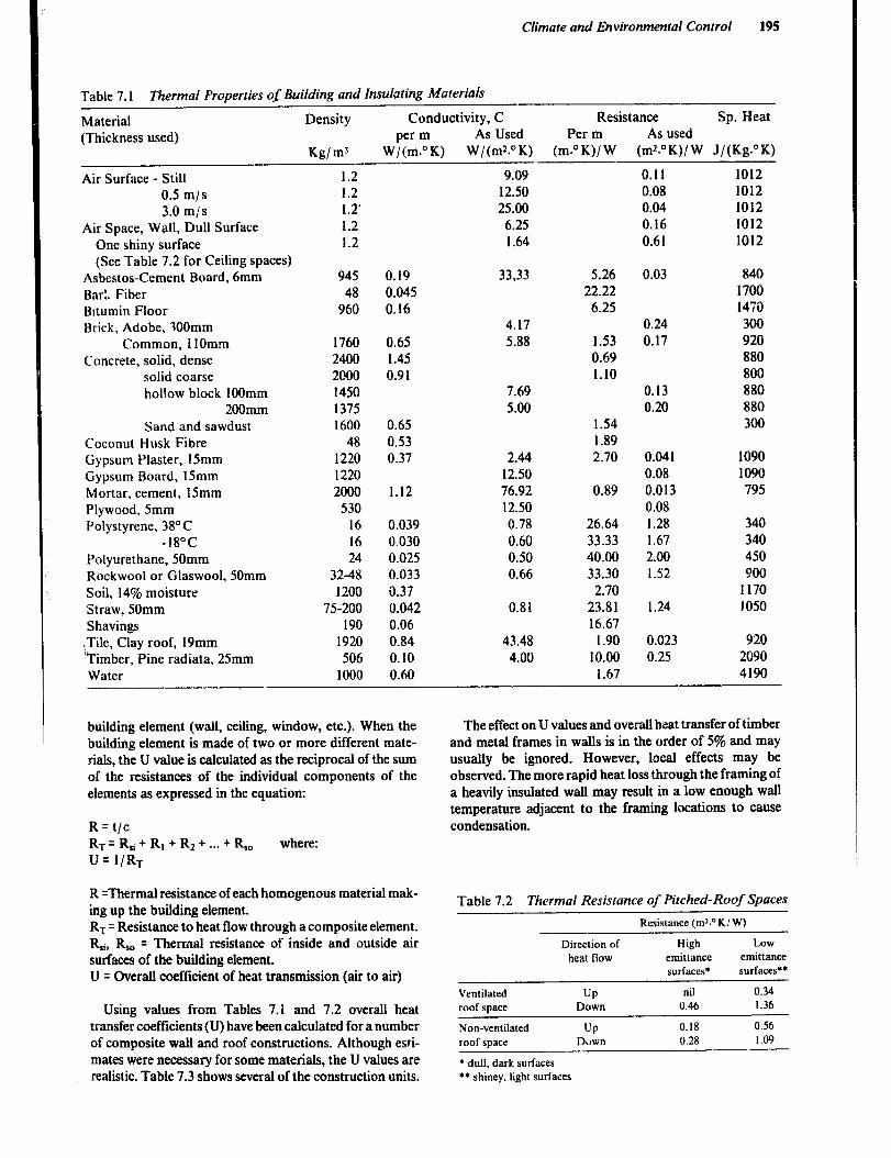
Climate and Eiw’ronmental Control 195
Table 7.1 Thermal Properties of Building and Insulating Materials
Material Density Conductivity, C Resistance Sp. Heat (Thickness used) per m As Used Per m As used
Kg/ m3 W/(m.“K) W/(mz.“K) (m.“K)/ W (mz.“K)/ W J/(Kg.“K)
1.2 9.09 0.11 1012 1.2 12.50 0.08 1012 1.2. 25.00 0.04 1012 1.2 6.25 0.16 1012 1.2 1.64 0.61 1012
Air Surface - Still 0.5 m/s 3.0 m/s
Air Space, Wall, Dull Surface One shiny surface (See Table 7.2 for Ceiling spaces)
Asbestos-Cement Board, 6mm BarL Fiber Bltumin Floor Brick, Adobe, 3OOmm
Common, 1lOmm Concrete, solid, dense
solid coarse hollow block 1OOmm
200mm Sand and sawdust
Coconut Husk Fibre Gypsum Plaster, 15mm Gypsum Board, 15mm Mortar, cement, 15mm Plywood, 5mm Polystyrene, 38” C
-18°C Polyurethane, 50mm Rockwool or Glaswool, 50mm Soil, 14% moisture Straw, 50mm Shavings
.Tile, Clay roof, 19mm ‘Timber, Pine radiata. 25mm Water
945 0.19 48 0.045
960 0.16
1760 2400 2000 1450 1375 1600
48 1220 1220 2000
530 16 16 24
32-48 1200
75-200 190
1920 506
1000
0.65 1.45 0.91
0.65 0.53 0.37
1.12
0.039 0.030 0.025 0.033 0.37 0.042 0.06 0.84 0.10 0.60
33,33 5.26 22.22 6.25
0.03 840 1700 14X 300 920 880 800 880 880 300
4.17 5.88
0.24 0.17 1.53
0.69 1.10
7.69 0.13 5.00 0.20
1.54 1.89 2.70 2.44
12.50 76.92 12.50 0.78 0.60 0.50 0.66
1090 1090 795
0.041 0.08 0.013 0.08 1.28 1.67 2.00 1.52
0.89
26.64 33.33 40.00 33.30 2.70
23.81 16.67
1.90 10.00
1.67
340 340 450 ?OO
1170 1050 0.81 1.24
0.023 0.25
920 2090 4190
43.48 4.00
The effect on U values and overall heat transfer of timber and metal frames in walls is in the order of 5% and may usually be ignored. However, local effects may be observed. The more rapid heat loss through the framing of a heavily insulated wall may result in a low enough wall temperature adjacent to the framing locations to cause condensation.
building element (wall, ceiling, window, etc.). When the building element is made of two or more different mate- rials, the U value is calculated as the reciprocal of the sum of the resistances of the individual components of the elements as expressed in the equation:
R=t/c RT=Rsi+RI+RZ+-..+&o where: U = l/RT
R =Thermal resistance of each homcgenous material mak- ing up the building element. R-r= Resistance to heat flow through a composite element. R,i, &, = Thermal resistance of inside and outside air surfaces of the building element. U = Overall coefftcient of heat transmission (air to air)
Using values from Tables 7.1 and 7.2 overall heat transfer coefficients (U) have been calculated for a number of composite wall and roof constructions. Although esti- mates were necessary for some materials, the U values are realistic. Table 7.3 shows several of the construction units.
Table 7.2 Thermal Resistance of Pitched-Roof Spaces
Resistance Crnz.OK! W)
Ventilated
roof space
Non-ventilated
roof space
Direction of
heat flow
UP Down
UP Duwn
High Low
emittance emittance
surfaces* surfaces**
nil 0.34
0.46 I .36
0.18 0.56
0.28 1.09
* dull. dark surfaces
l * shinev, light surfaces
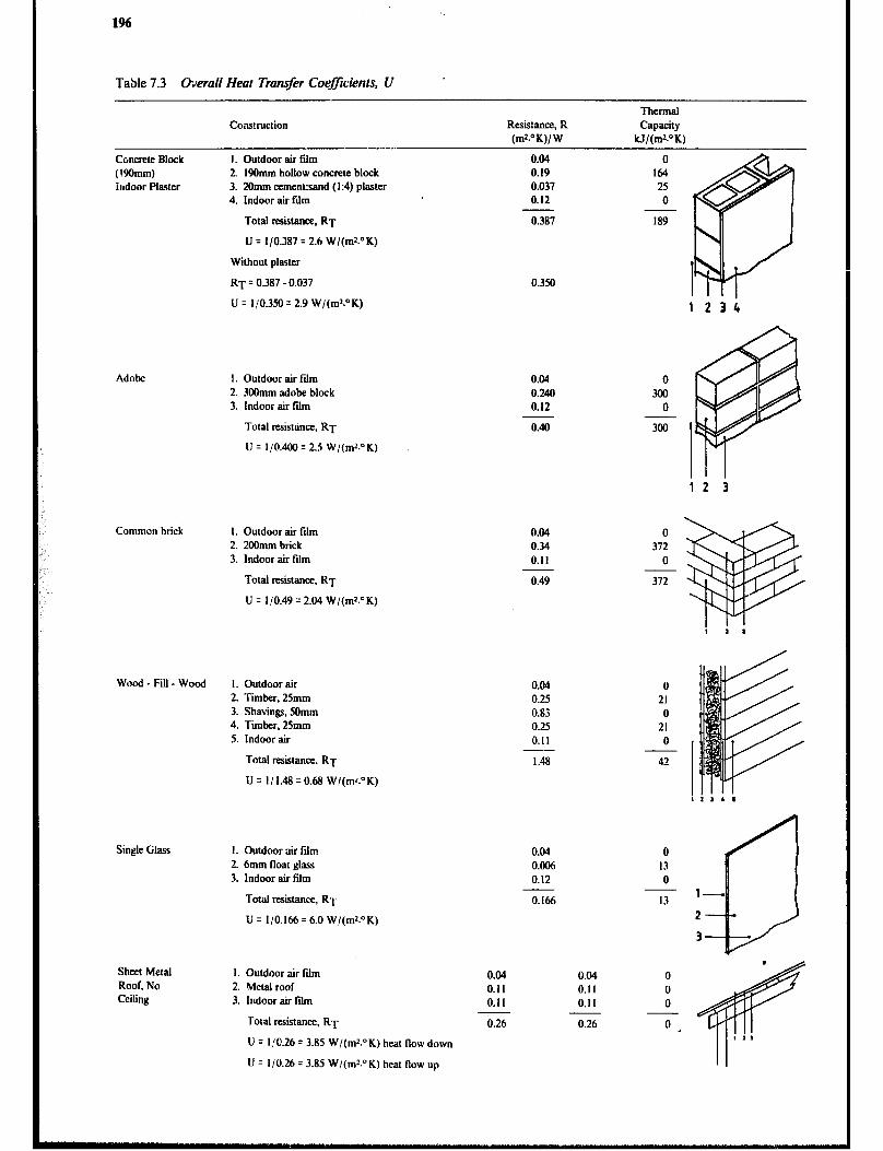
Table 7.3 &era11 Heat Transfer Coeficients, U
Construction
.
Resisttce, R
(mr.OK)/ W
Thermal
Capacity
W/(mz.DK)
Concrete Block
(t9Omm)
indoor Plaster
1. Outdoor air fdm
2. 19Omm hollow concrete block
3. 20mm cement:sand (1:4) plaster
4. Indoor air fiim
Total resistance, RT
U = l/O.387 = 26 W/(ms.OK)
Without plaster
RT = 0.387 - 0.037
U = l/O 350 = 2 9 W/(m*.OK) . .
Adobe I. Outdoor air film
2. 300mm adobe block
3. Indoor air fdm
Total tesistana, RT
U = l/O.400 = 2.5 W/(mr.‘K)
Common brick I. Outdoor air film
2. 2OOmm brick
3. Indoor air film
Total resistance. RT
U q l/O.49 = 2.04 W/(mz.“K)
Wood - Fill - Wood I. Outdoor air
2. Timber, 25mm
3. Shavings, 50mm
4. Timber, 25mm
5. Indoor air
Total msistance. RT
U = I/ I.48 q 0.68 W/(mL”K)
Single Glass
Sheet Metal
Roof, No Ceiling
I. Outdoor air film
2. 6mm float ghtss
3. Indoor air film
Total resistance. RT
U q 110.166 q 6.0 W/(mr.OK)
I. Outdoor air fiim
2. Metal roof
3. Indoor air film
Total resistance, RT
U = I(O.26 = 3.85 W/(mL°K) heat flow down
U = 110.26 = 3.85 W/(mz.“K) heat flow up
0
164
25
0
0.387
0.350
0.04
0.25
0.83
0.25
0.11
1.48
0.04
0.006
0.12
0.166
0.04
0.11
0.11
0.26 0.26
189
0
372
0
372
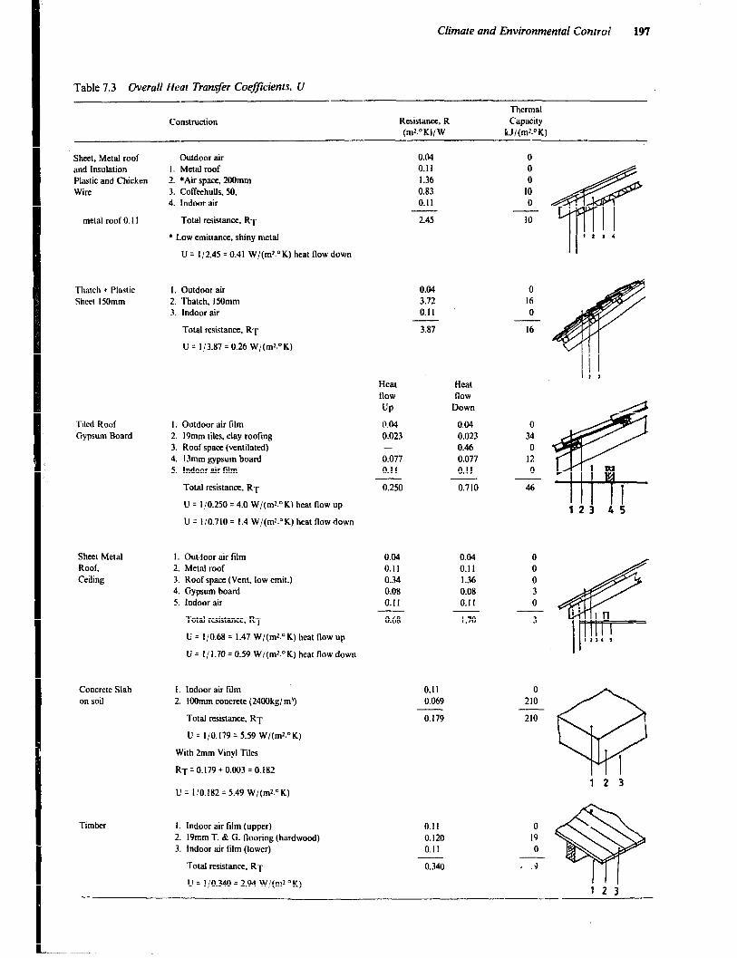
Climate and Environmental Control 197
Table 7.3 Overall Heat Transfer Coef$cients, I/
Thermal
Construction Resistance, R Capacity
(ml-OK)/ W kJl(mz.OK)
Sheet, Metal roof
and Insulation
Plastic and Chicken
Wire
metal roof 0. II
Outdoor air
I. Metal roof
2. *Air space. 2OOmm
3. Coffeehulls. 50,
4. Indoor air
Total resistance, RT
l Low emittance, shiny metal
U = 112.45 = 0.41 W/(m2.“K) heat flow down
0.04
0.11
1.36
0.83
0.11
2.45
Thatch + Plastic
Sheet ISOmm
I. Outdoor air 0.04 0
2. Thatch, ISOmm 3.72 I6
3. Indoor air 0.11 0
Total resistance. RT
U = l/3.87 = 0.26 W/(mz.“K)
3.87 16
ir I Heat
now
UP
0.04
0.023
0.077
0.11
0.250
Heat
flow
Down
0.04
0.023
0.46
0.077
0.1 I
0.710
Tiled Roof
Gypsum Board
I. Outdoor air film
2. 19mm tiles, clay roofing
3. Roof space (ventilated)
4. 13mm gypsum board
5. Indoor air film
Total resistance. RT
U = 110.250 = 4.0 W/(mr.“K) heat flow up
U = l/O.710 = I.4 W/(mr.“K) heat Row down
0
34
0
12
0
46
123 45
Sheet Metal
Roof,
Ceiling
1. Out.loor air ftlm
2. Metal roof
3. Roof space (Vent, low emit.)
4. Gypsum hoard
5. indoor air
0.04 0.04
0.1 I 0.11
0.34 1.36
0.08 0.08
0.11 0.11
Total resistance. RT 0.68 1.70
U = l/0.68 = 1.47 W/(m’.“K) heat flow up
U = I/ 1.70 = 0.59 W/(m’.OK) heat flow down
Concrete Slab
on soil
I. Indoor air fidm
2. IOOmm concrete (24OOkg,‘m’)
Total resistance, RT
U = l/O.179 = 5.59 W/(m’.“K)
With 2mm Vinyl Tiles
R~=0.179+0.003=0.182
U = 110.182 = 5.49 W/(mr.“K)
0.11
0.069
0
210
210
-@
1
1
0.179
Timber 1. Indoor air film (upper) 0.11 2. 19rnm T. 8: G. Rooting (hardwood) 0.120 3. Indoor air tilm (lower) 0.11
Total resistance, RT
U = l/O.340 = 2.94 W/(mz.“K)
0.340

198
Rate of Overall Heat Loss or Gain from a Building Once the U values have been calculated for each element of the building (walls, ceiling, windows, doors, etc.), the area of each element is determined, and design temperatures for inside and outside are chosen. It follows then that for each building element:
Q=ArI-JxaT where: Q = Total heat transfer rate through an element (W) A = Area of building element (mZ) U = Coefficient of heat transfer for the element W/(mz.” K) AT = Temperature differential across element (” K)
For the building as a whole the total heat exchange rate will equal the sum of the Q values. Total heat transfer in Joules for a given period may be found by multiplying kilowatts by 3.6 Megajoules times the number of hours. Figure 7.1 provides some rough approximations of maxi- mum and minimum temperatures for design purposes. Temperature data for the immediate area in which the building will be constructed will provide the most accurate results.
Solar Load In the countries of East and South-east Africa the effect of solar radiation can be appreciable dunng some seasons and at certain times of the day. The orientation, design, and materials used will all influence the amount of solar heat gain to which a building is subjected.
A method of determining the degree and extent of solar gain has been developed which is called sol-air. This con- cept provides a solar increment in the southern hemisphere to be added to the design air temperature used for horizon- tal roofs and northerly facing walls. These increments range from 10 to 30°C.
However, they apply for only a few hours per day and become of less significance if the building is designed to offset the effects of solar radiation. Two examples illustrate how this can be accomplished.
In an area of high diurnal-nocturnal temperature differ- ence, the roof and walls of a building should be constructed of materials with a great deal of mass (adobe bricks or rammed earth). The resulting high thermal capacity will limit both daytime temperature rise and the nighttime temperature drop and thus the high solar-radiation effect is reduced to a minimum.
In the case of a ,efrigerated store, it would bt desirable to use a roof design that allows attic ventilation and that is covered with a lightcoloured reflective surface which when combined, will minimize the effect of solar radiation on the store to a minimum.
Example of Heat Loss from Buildings Given: Two homes in Lesotho. One is constructed with adobe block walls and a thatch roof, while the other is
Figure 7.1 a Highest mean monthly maximum tempera- ture (O C).
km
Figure 7.1 b Lowest mean monthly minimum tempera- ture ( 0 C).
made of hollow core concrete blocks with a sheet metal roof. Each house is 5 metres square, 2 metres high at the eaves, 3 metres at the ridge, has 1 m2 of window and lSm* of timber door. Find the heat lost from each house when the temperature is O°C outside and is 1YC inside.
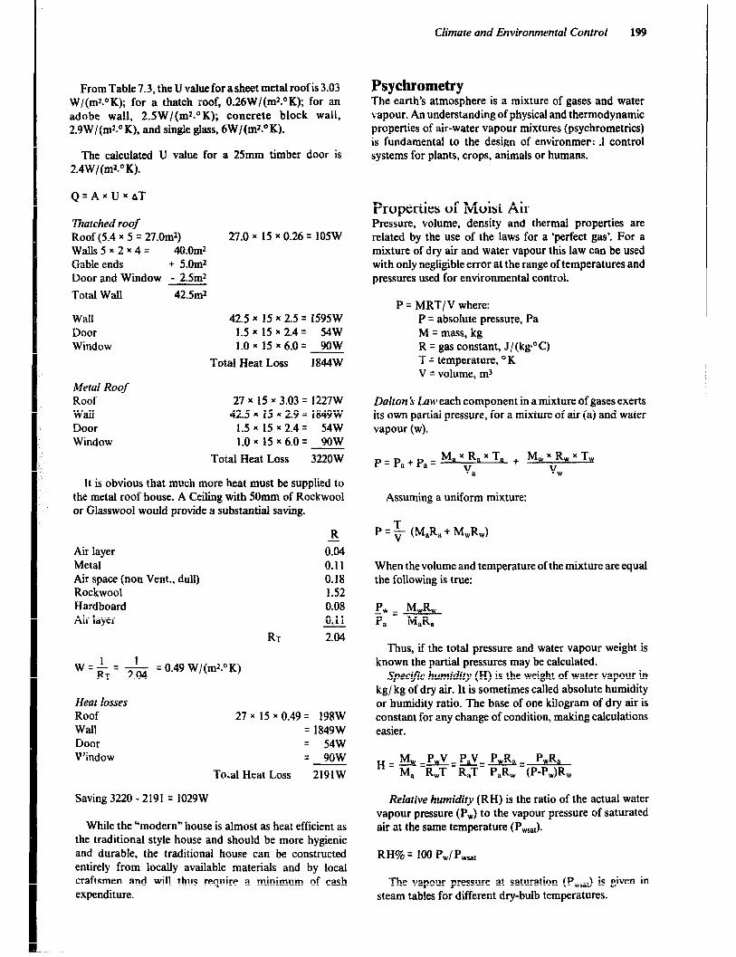
Climate and Environmental Control 199
From Table 7.3, the U value for a sheet metal roof is 3.03 W/(mz.“K); for a thatch roof, 0.26W/(m2.‘K); for an adobe wall, 2.5W/(ms.°K); concrete block wall, 2.9W/(mr.OK), and single glass, 6W/(ms.OK).
The calculated U value for a 25mm timber door is 2.4W/(mz.OK).
Q=AxUxaT
Thatched roof Roof (5.4 x 5 = 27.0m2) 27.0 x 15 x 0.26 = 105W Walls5~2~4= 40.0m2 Gable ends + 5.Om2 Door and Window - 2.5m2
Total Wall 42.5m2
Wall 42.5 x 15 x 2.5 = 1595W Door 1.5 x 15 x 2.4 q 54W Window 1.0~ 15x6.0= 9oW
Total Heat Loss 1844W
Metal Roof Roof 27 x 15 x 3.03 = 1227W Wall 42.5 x 15 x 2.9 = 1849W Door 1.5 x 15 * 2.4= 54W Window 1.0 x 15 x 6.0 = 9OW
Total Heat Loss 3220W
It is obvious that much more heat must be supplied to the metal roof house. A Ceiling with 50mm of Rockwool or Glasswool would provide a substantial saving.
Air layer Metal Air space (non Vent., dull) Rockwool Hardboard Air layer
R
0% 0.11 0.18 1.52 0.08 0.11
RT 2.04
1 1 w =RT= 2.04
- = 0.49 Wl(rn2.O K)
Heat losses Roof Wall Door Window
27 x 15 * 0.49 = 198W q 1849W = 54w = 9ow
Toial Heat Loss 219lW
Saving 3220 - 2191 = 1029W
While the Umodem” house is almost as heat efficient as the traditional style house and should be more hygienic and durable, the traditional house can be constructed entirely from locally available materials and by local craftsmen and will thus require a minimum of cash expenditure.
Psychrometry The earth’s atmosphere is a mixture of gases and water vapour. An understanding of physical and thermodynamic properties of air-water vapour mixtures (psychrometrics) is fundamental to the design of environmer; .l control systems for plants, crops, animals or humans.
Properties of Moist Air Pressure, volume, density and thermal properties are related by the use of the laws for a ‘perfect gas*. For a mixture of dry air and water vapour this law can be used with only negligible error at the range of temperatures and pressures used for environmental control.
P = MRT/.V where: P = absolute pressure, Pa M = mass, kg R = gas constant, J/(kg’C) T = temperature, OK V q volume, rnJ
Dalton 5 Low each component in a mixture of gases exerts its own partial pressure, for a mixture of air (a) and water vapour (w).
P=Pa+pa= Max>XTa + MwjRwxTw a w
Assuming a uniform mixture:
P = 5 (M,R, + M,R,)
When the volume and temperature of the mixture are equal the following is true:
-w - WJL P Pa - MaRa
Thus, if the total pressure and water vapour weight is known the partial pressures may be calculated.
Specific humidity (H) is the weight of water vapour in kg/ kg of dry air. It is sometimes called absolute humidity or humidity ratio. The base of one kilogram of dry air is constant for any change of condition, making calculations easier.
H = & - pwv _ hv= PwR, = P&a M, R,T R,T P,R, (P-Pw)R,
Relative humidity (RH) is the ratio of the actual water vapour pressure (P,,) to the vapour pressure of saturated air at the same temperature (P,&.
RI-I% = 100 Pwl Pm,,
The vapour pressure at saturation (Pw,& is given in steam tables for different dry-bulb temperatures.

Specific volume is the volume of dry air per mass of dry air.
Humidvolume is the volume of an air-moisture mixture per mass of dry air. In ventilation calculations, the volume is in cubic metros of mixture (air + water vapour) per kg of dry air. The base of one kg of dry air is used because the kg of dry air entering and leaving the system in a given time will be constant once a steady-state flow is established. Humid volume increases as the temperature or water vapour content increases. The humid volume of air-water vapour mixtures is given in standard thermodynamic tables or may be read from a pschrometric chart.
Temperatures - air-water vapour mixtures can be des- cribed by the dry-bulb and either the wet bulb or dew-point temperatures:
0 dry-bulb temperature is measured with a common thermometer,thermocouple or thermisters; 0 wet bulb temperature is the temperature at which water, by evaporating into moist air, can bring the air to saturation adiabatically in a steady - state condition; 0 dew point temperature is the temperature at which moisture starts to condense from.air cooled at constant pressure and specific humidity.
Enthalpy (h) is the heat energy content of an air-water vapour mixture. The energy is a combination of both sensible heat (indicated by dry-bulb temperature) and lat- ent heat of vaporization (energy content of the wattr vapour). Enthalpy scales appear on pschrometric charts expressed as kJ/ kg of’ dry air. Enthalpy can be calculated from the equation:
h=Sxbt,+HXhw where:
S = Specific heat of dry air, 1004 kJ/(kg.OK) tdb = dry bulb temperature H = Specific humidity hw = enthalpy of water vapour, kJ/ kg water vapou-r
Thus:
h = 1.004 x t& + H(2454 + 1858 x tdb) kJ/ kg where:
2454 = latent heat of vaporization, kJ/ kg 1858 = Specific heat of water vapour, kJ/ (kg.O K)
Psychrometric Chart A psychrometric chart (Figure 7.2 and appendix V4-6) is a graphical representation of the thermodynamic properties of moist air. It is useful for solving engineering design problems. Charts for agricultural applications are usually corrected to standard atmospheric pressure of 101.325 kPa. However charts for other elevations are available. The following properties are shown on d psychrometric chart:
l wet-bulb 0 dew-point temperatures l moisture content or spccitic humidity l enthalpy 0 relative humidity 0 specific volume 0 humid volume
The intersection of any two property lines establishes a given state, and all other properties can be read from that point. The changes that take place between any two points are of particular use. The vertical lines show dry-bulb tempetatures; the curved lines, relative humidity; the slant lines, wet bulb temperatures and enthalpy; the horizontal lines, dew point temperatures and specific humidity, and the steep slant lines, specific and humid volume.
The wet- and dry-bulb temperature for a building area may be read from a psychrometer and then used to estab- lish a point of intersection on the chart. Psychrometers consist of two thermometers mounted close together, one of which has a wick on the bulb that is wet with a few drops of distilled water. Air movement is necessary. A sling psychrometer, which is actually swung in the air, is the simplest and least expensive. However, for locations with restricted space a motorized psychrometer must be used. The air movement in a ventilation duct is adequate to provide accurate readings from stationary temperature sensors.
Air-water Vapour Mixture Processes Conditioning of air-water vapour mixtures involves heat- ing, cooling, humidifying dehumidifying or some combi- nation of these factors.
Sensible heat is the heat added to air without changing its specific humidity. Applications of sensible heating include heated-air grain drying and winter h.:ating of room air in cool-climate homes. Sensible cooling is the removal of heat at a constant spe- cific humidity. An example is the air passing over acooling coil having a surface temperature above the dew point of the air. The final temperature cannot be below the initial dew-point temperature or water vapour condenses and the process removes latent heat.
,f Dry bulb temp
Sensible Heating
Specific Humidity
l dry-bulb

Climate and Environmental Control 201
5 t
,
‘peciflc humidity
Dry bulb temp
Sensible Cooling
Lines a and b are starting and ending dry-bulb air temperature hnes in both processes. Lines c and d show starting and endingenthalpy values. The fact that line 1-2 is horizontal indicates that there was no change in specific humidity in either process. Lines e and f show that the relative humidity dropped in the heating process and rose in the cooling process. Evaporative cooling is an adiabatic saturation process (no sensible heat gained or lost) and follows upward along a constant wet-bulb temperature line on the chart. Air to be cooled is brought into contact with water at a temperature
PSYCHROMETRIC CHART NORMAL TEMPERATURES
equal to the wet-bulb temperature of the air. The sensible heat of the initial air evaporates the water, lowering the air’s dry-bulb temperature. Sensible heat is converted to latent heat in the added vapour, so the process is adiabatic. Evaporative cooling is effective in hot dry climates where wet-bulb depression (the difference between dry-bulb and wet-bulb temperatures) is large and where the disadvan- tage of increased humidity is more than offset by a rela- tively large temperature drop.
__--_-
d c
Dry bulb temp
Evaporative Cooling Process
Evaporating moisture from a to b cools the air from c to d. As 1 and 2 are on the same enthalpy line, the process is adiabatic (no change in heat) the relative humidity rises from 1 to 2.
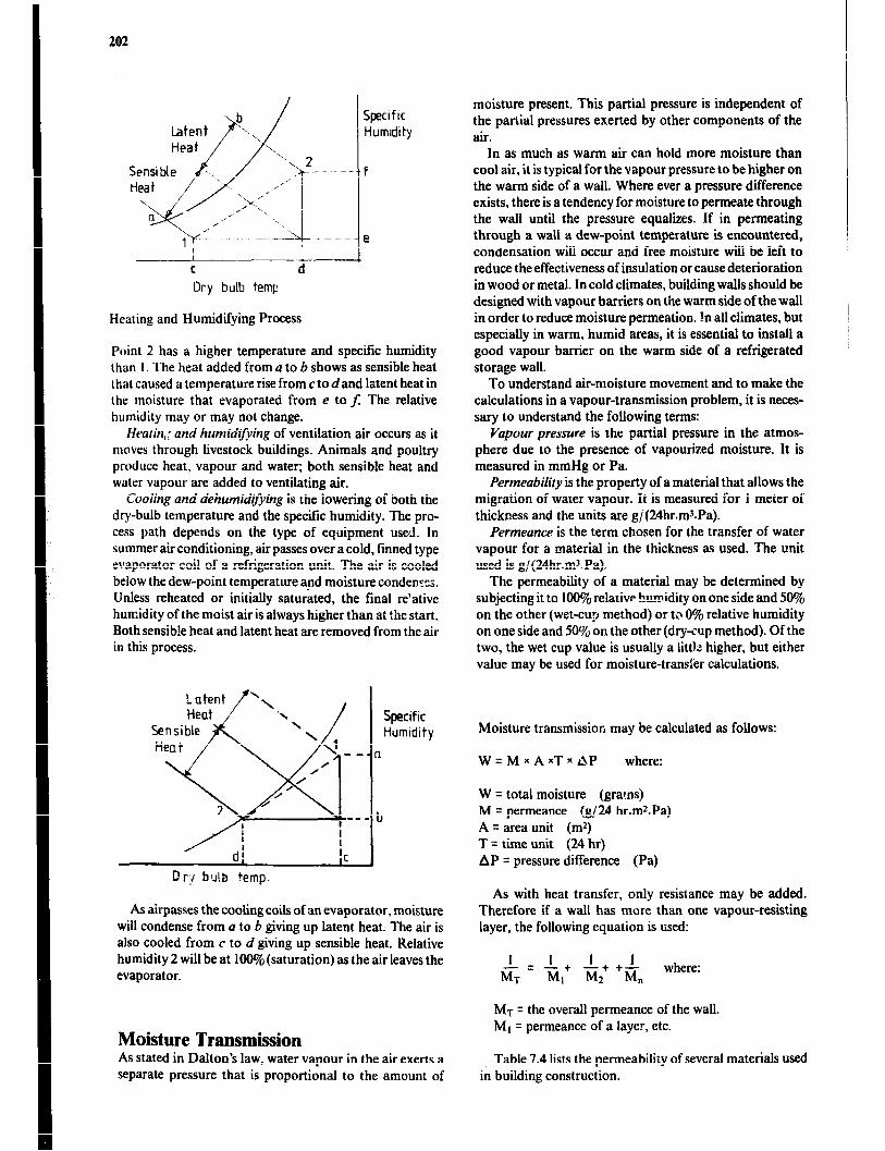
202
I
C d
Dry bulb temp
Specif Ic Humldi ty
f
e
Heating and Humidifying Process
Point 2 has a higher temperature and specific humidity than I. The heat added from a to b shows as sensible heat that caused a temperature rise from c to d and latent heat in the moisture that evaporated from e to f. The relative humidity may or may not change.
Heatin;: and humidl$kg of ventilation air occurs as it moves through livestock buildings. Animals and poultry produce heat, vapour and water; both sensible heat and water vapour are added to ventilating air.
Cooling and dehumidgying is the lowering of both the dry-bulb temperature and the specific humidity. The pro- cess path depends on the type of equipment used. In summer air conditioning, air passes over a cold, finned type evaporator coil of a refrigeration unit. The air is cooled below the dew-point temperature and moisture conden::;. Unless reheated or initially saturated, the final re’ative humidity of the moist air is always higher than at the start. Both sensible heat and latent heat are removed from the air in this process.
Or;4 bulb temp.
Specific Humidity
As G-passes the cooling coils of an evaporator, moisture will condense from a to b giving up latent heat. The air is also cooled from c to d giving up sensible heat. Relative humidity 2 will be at lOODjo(saturation) as the air leaves the evaporator.
Moisture Transmission As stated in Dalton’s law, water vapour in the air exerts a separate pressure that is proportional to the amount of
moisture present. This partial pressure is independent of the partial pressures exerted by other components of the air.
In as much as warm air can hold more moisture than cool air, it is typical for the vapour pressure to be higher on the warm side of a wall. Where ever a pressure difference exists, there is a tendency for moisture to permeate through the wall until the pressure equalizes. If in permeating through a wall a dew-point temperature is encountered, condensation will occur and free moisture wiII be left to reduce the effectiveness of insulation or cause deterioration in wood or metal. In cold climates, building walls should be designed with vapour barriers on the warm side of the wall in order to reduce moisture permeation. In alI climates, but especially in warm, humid areas, it is essential to install a good vapour barrier on the warm side of a refrigerated storage wall.
To understand air-moisture movement and to make the calculations in a vapour-transmission problem, it is neces- sary to understand the following terms:
Vapour pressure is the partial pressure in the atmos- phere due to the presence of vapourized moisture. It is measured in mmHg or Pa.
Permeability is the property of a material that allows the migration of water vapour. It is measured for 1 meter of thickness and the units are g/(24hr.mXPa).
Permeance is the term chosen for the transfer of water vapour for a material in the thickness as used. The unit used is g/(24hr.mXPa).
The permeability of a material may be determined by subjecting it to 100% relative humidity on one side and 50% on the other (wet-cup method) or to 0% relative humidity on one side and 50% on the other (dry-cup method). Of the two, the wet cup value is usually a lit& higher, but either value may be used for moisture-trans:er calculations.
Moisture transmission may be calculated as follows:
W=MxAxTxJP where:
W = total moisture (grar.ns) M = permeance (g/24 hr.m*.Pa) A q area unit (m*) T = time unit (24 hr) AP = pressure difference (Pa)
As with heat transfer, only resistance may be added. Therefore if a wall has more than one vapour-resisting layer, the following equation is used:
I I 1 I - = -+ -+ +- MT MI M2 Mn
where:
MT = the overall permeance of the wall. MI = permeance of a layer, etc.
Table 7.4 lists the permeability of several materials used in building construction.

Table 7.4
Mnrerial
Moisture Permeability cf Materials
Pnzmeability Permcance
/ m thickness Thickness as used
p/(24hr-mJ.Pa: g/(24hr.mz.Pa)
x10-3
Air Exterior plywood 6mm
Pine timber
Concrete
Asphalt roofing
Aluminium paint
Latex paint
Polystyrene
Extruded
Bead
Polyurethane
Polyethcne 0. Imm
Polyethene 0.2mm
15.3
3.45 0.053 - 0.68
0.38
0.23 I .5 - 2.48
27.23
0.15
0.26 - 0.75
0.53 - 0.23
0.4
0.2
Vapor Barriers Any enclosed wall that has an appreciable temperature difference or humidity difference between the two sides for a substantial part of the time should have a vapour barrier installed on or near the warm or humid side. In cold climates this applies to the wall in any enclosed building that is heated or where the humidity is high. In warm climates it applies to air-conditioned or refrigerated build- ings primarily.
Probably the most effective vapour barrier that is also reasonable in cost is polyethene sheet. The vapour barrier should be as continuous as possible. This can be achieved by using large sheets with well overlapped and sealed joints and as few nail holes as possible.
Condensation on Surfaces and Within Walls If the insulation in the wall of a refrigerated storage is inadequate or if it has defective spots, the outside of the wall may be cool enough to be below the dew-point temperature. The result will be condensation on the outer wall surface. Remedies for this condition are:
l better insulation l reduction of outside humidity, or l increased air movement across the wall.
Materials such as stone, concrete and brick are not affected by condensation.
Condensation within the wall is more serious and results from either the absence of a vapour barrier or a defective barrier. In that situatio?! moisture moves into the wall from the warm side until it reaches an inner wall layer that is below the dew-point temperature. The resulting condensa- tion soon reduces the effectiveness of the insulation and causes permanent damage. Remedies for this situation are:
l a better vapour seai on the warm side
Climate and Environmental Control 203
l a more permeable layer on the cold side, or l a reduction in humidity on the warm side through ventilation or other means.
Ventilation Ventilation is one of several methods used to control the environment in farm buildings where it fulfihs two main functions: the comrol of temperature and the control of moisture within a building. Ventilation may also be neces- sary to maintain adequate levels of oxygen and to remove generated gases, dust ano odours.
There is a considerable range of ventilation requirements that depend on the local climatic conditions and the spe- cific enterprise being senved. The following examples will illustrate:
1 A cattle shelter in a tropical climate requires little more than shade from a roof with the structure sited to obtain maximum breeze. 2 A cat::= shelter in a cold climate (frost occurs in season) may be open on the sunny side and provided with ventila- tion openings at the ridge and along the rear eaves. The temperature will be cold but condensation will be controlled. 3 A poultry house (cage-equipped) in a cold climate, if heavily insulated, can be kept comfortabiy warm while mechanical ventilation removes excess moisture and odours. 4 Potatoes that are stored in either a mild or a cold climate may be cooled by ventilation alone. Continual air movement is requisite to maintaining a uniform environ- ment. The amount of insulation used will be dictated by the lowest temperature expected.
A great deal of research has been done to determine the ideal environmental conditions for various classes of live- stock and types of plant and animal products. Within economic constraints, the nearer these ideal conditions can be maintained, the more successful the enterprise will be. That is, meat animals will gain faster and more efficiently, dairy cattle will produce more milk, and crop storages will maintain better quality and reduce losses.
Natwal Ventilation
Thermal Convection or Stack Effect Natural ventilation is provided from two sources-thermal convection and wind. Air which is heated with respect to the surrounding air is less dense and experiences ‘an upthrust due to thermal bouyancy.
Whenever a building contains livestock, the production of sensible metabolic energy is always available to wdrln the air entering from the outside. Similarly air may be heated in a greenhouse by inooming radiation. Provided there are two apertures with a height differential, convec- tion currents will force the heated, less dense air out of the
204
upper aperture to be replaced by an equal volume of cooler, denser air from outside.This is referred to as “Stack effect”
Hence natural ventilation by stack effect can provide the minimum ventilation requirement under winter condi- tions. While this system may be less expensive than a mechanical system, it will also be less positive in action and more difficult to control.
A building that is open on one side may be ventilated naturally by leaving the ridge open for an outlet and a slot along the rear for an inlet. An enclosed building may be more positively ventilated with stack outlets and correctly sized inlets.
To determine the inlet and outlet areas required to pro- vide a given ventilation rate by thermal convection, the following e.quation based on stack effect theory can be used:
1 1 p=yii-j=
2g x h x H, Ti(P x S x V + W)V’
where:.
Ai = inlet (mz) A, = outlet area (mz) g = acceleration due to gravity (9.76 rn/ ~2) h = height difference, inlet to outlet (m) H, = heat supplied to building (W)
TP = absolute temperature in building (“K = 273” C) P = density of air in building (kg/ ms), 1.175 at 25” C s = specific heat of air (1005 J/ kg0 C) V = ventilation rate (mJ/s) W = heat loss through building shell (W/“(Z)
The values in Figure 7.3a and b were developed using tF,ts equation. The values in (a) are for a solar-flue drier, *vhile those in (b) more closely fit the conditions in a building.
Natural ventilating systems may be non-adjustable, manually adjustable, or automatically controlled. In as much as natural systems are likely to be chosen for econ- omy reasons where conditions are not severe, manual adjustment should be the method of choice in most cases.
Ventilation Due to Wind As the wind flows around a building, gusts and lulls create regions in which the static pressure is above or below the atmospheric pressure in the free air stream. In general, these pressures are positive on the windward side, resulting in an inflow of air, and negative on the leeward side, resulting in an outflow of air. Pressures are generally nega- tive over low-pitched roofs.
Mechanical Ventilation Compared to natural ventilation, mechanical ventilation with the use of fans is more positive in its action, less affected by wind, and more easily controlled. Initial instal- lation will usually cost more and there is the added cost of
operation. However, in many cases the advantages of mechanical ventilation outweigh the added expense.
Exhaust vs Pressure Systems There are two main types of mechanical ventilating sys- tems, namely, pressure and exhaust. In a pressure system the fan blows air through inlet openings into the building creating a positive indoor pressure that pushes air out of he building through the outlet openings. In exhaust venti- lation the fan expels air from the building creating a lower than atmospheric pressure inside the building. The pres- sure difference between outside and inside causes ventila- tion air to flow in through the inlets. For good air flow control is important that the building is tight.
The exhaust ventilation system is popular because it is easier to control the.distribution of the incoming air and is generally less expensive and complex than a pressure sys- tems. However, there are situations when the pressure system (one that forces air into the building) performs better. These includes:
1 very dusty conditions that tend to load up the fans, 2 buildings with excessively loose construction (many cracks), and 3 when continuous recirculation is required.
Under some circumstances pressure systems may cause humid air to be forced into building walls and ceilings. This can result in condensation and damage to wood and other materials.
A mechanical ventilation system is made up of three main components: fans, airdistribution system and con- trols to regulate fans.
Fans and Blowers Axial-flow fans are normally divided into propeller and tubeaxial types. They move air parallel to the shaft and are the types most widely used. Centrifugal (radial flow) fans (blowers) discharge air at right angles to the shaft and often operate at substantial pressures.
Propeller fans are the least expensive and the easiest to install. A propeller fan may have 2 to 6 or more blades. Generally the more blades, the greater the pressure the fan will develop. The best propeller fans have a close-fitting curved inlet shroud or inlet ring which improves the efti- ciency of the fan. Propeller fans are most suited to moving large volumes cf air at pressures in the range of 30 to 50Pa (3 to 5mm of water) and they are the most commonly used in conventional farm building ventilation. Figure 7.5.
The tubeaxialfan is a more refined version of the pro- peller fan (Figure 7.6). It has aerofoil-shaped fan blades on an impeller with a large hub all mounted in a close-fitting tube. Tubeaxial fans are capable of operating against higher static pressures than ordinary propeller fans and are made for ducted installations with high resistance to air flow. If it is necessary for a tubeaxial fan to operate under very considerable pressure, it may be designed with two impellers in tandem, described as a multi-stage model.
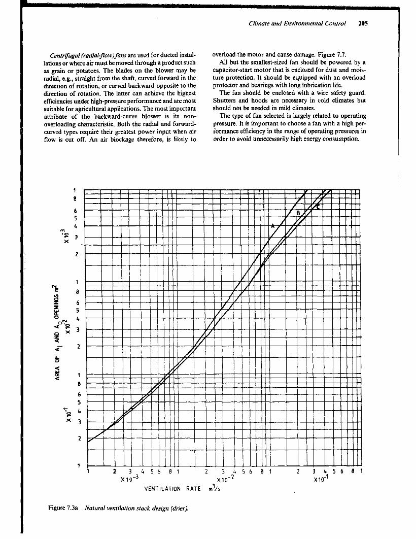
Centrifugal (radial-Jow)fans are used for ducted instal- overload the motor and cause damage. Figure 7.7. lations or where air must be moved through a product such All but the smallest-sized fan should be powered by a as grain or potatoes. The blades on the blower may be capacitor-start motor that is enclosed for dust and mois- radial, e.g., straight from the shaft, curved forward in the ture protection. It should be equipped with an overload direction of rotation, or curved backward opposite to the protector and bearings with long lubrication life. direction of rotation. The latter can achieve the highest The fan should be enclosed with a wire safety guard. efficiencies under high-pressure performance and are most Shutters and hoods are necessary in cold climates but suitable for agricultural applications. The most important should not be needed in mild climates. attribute of the backward-curve blower is its non- The type of fan selected is largely related to operating overloading characteristic. Both the radial and forward- pressure. It is important to choose a fan with a high per- curved types require their greatest power input when air iormance efficiency in the range of operating pressures in flow is cut off. An air blockage therefore, is likely to order to avoid unnecessarily high energy consumption.
6
‘; g:
x 3
2
1
Climate and Environmental Control 205
I I II I !!!I!1 I III !!lllll I! I IllIll 1 2 3 1,56 81 2 v s b a ' 2 3 456 81
x1o-3 x10 x10-l
VENTILATION RATE r&s
Figure 7.3a Natural ventilation stack design (drier).
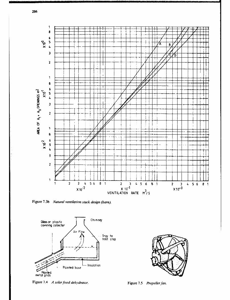
206
0 ‘S X
N ‘e X
1 1 2 3 456 81 2 3 456 01 2 3 456 01
x 1o-2 x 10-l VENTILATION RATE M3, 5
x10-o
Figure 7.3b Natural ventilation stack design (barn).
Gloss or plastic cowing collector
metal grids
Figure 7.4 A solar food dehydrator.
to crop
Figure 7.5 Propeller fan.

Climate and Environmental Control
<pcl -
Figure 7.8a Manometer. measures static pressure. Figure 7.6 Tubeaxial-jlow fan.
Figur: 7.7 Centrgugal blower. Figure 7.8b Float t.vpegauge, measuresstaticpressure or Air Velocity.
Figure 7.8 Simple Instruments to measure pressure and air velocitSv. <Pa = less than the atmospheric pressure. Static Pressure
When an exhaust fan is instailed in the wall of a closed building, a lowered air pressure will develop inside, or if the fan blows air into the building, a slight pressure increase will occur. Manometers or draught gauges are two simple but dependable devices which can be used to measure the small pressure differences that exist. Figure 7.8. They are usually calibrated to read in millimeters of water. That is, if the two columns of water in a glass “U” tube are equal, and then a plastic tube is connected from one side (4 the U tube to a building with an operating fan, the columns will become unbalanced. The difference is the millimeters of static pressure.
Fan Ratings and Selection A fan performance is usually related in terms of volume of air moved expressed in cubic metres per second (ms/s) against a pressure or resistance to air flow expressed in Pa or mm of water static pressure (mmWG). Free&delivery is nearly meaningless since that situation seldom exists. Performance curves, available from the manufactu -er, out- line the performance of fans at different operating pres- sures. These curves also illustrate the maximum or cut-off
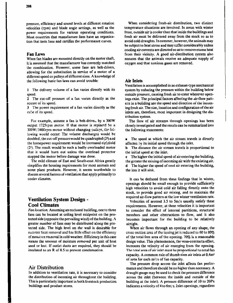
208
pressure, efficiency and sound levels at different rotation velocities (rpm) and blade angle settings, as well as the power requirements for various operating conditions. Most countries that manufacture fans have an organiza- tion that tests fans and certilies the performance curves.
Fan Laws When fan blades are mounted directly on the motor shaft, it is assumed that the manufacturer has correctly matched the combination. However, some fans are belt-driven, allowing for the substitution in service of a motor of a different speed or pulleys of different sizes. A knowledge of the following basic fan laws can avoid trouble:
1 The delivery volume of a fan varies directly with its speed. 2 The cut-off pressure oi a fan varies directly as the square of its speed. 3 The power requirement of a fan varies directly as the cu5e of its speed.
For example, assume a fan is belt-driver. by a 300W output 1725rpm motor. If that motor is replaced try a 3OOW,/34OOrpm motor without changing puiisys, the fo!- lowing would occur: The volume discharged would be doubled, the cut-off pressurewould be quadrupled (22) and the horsepower requirement would be increased eip,Mold (23). The result would be such a badly overloaded motor that it would burn out unless the overload protector stopped the motor before damage was done.
The mild climate of East and South-east Africa greatly simplifies the housing requirements for most animals and some plant products. However, it seems worthwhile to discuss several factors of ventilation that apply primarily to cooler climates.
Ventilation System Design - Cool Climates Fun locution. Assuming an enclosed building, one to three fans can be located at ceiling level midpoint on the pro- tected side (opposite the prevailing wind) of the building. A greater number of fans may be distributed along the pro- tected side. The high level on the wall is desirable for sulmmer heat removal and has little effect on the efftciency of motstme removal in cold weather. Efficiency in this case means the amount of moisture removed per unit of heat used or lost. If outlet ducts are required, they should be insulated to an R of 0.5 to prevent condensation.
Air Distribution In addition to ventilation rate, it is necessary to consider the distribution of incoming air throughout the building. This is particularly important in both livestock production buildings and product stores.
When considering fresh-air distribution, two distinct temperature situations are involved. In areas with winter frost, outside air is cooler than that inside the buildings and fresh air must be delivered away from the stock so as to avoid cold draughts. In summer, however, the animals may be subject to heat stress and may suffer considerably unless cooling air currents are directed so as to remove excess heat from their vicinity. A good airdistribution system also ensures that the animals receive an adequate supply of oxygen and that noxious gases are removed.
Air Inlets Ventilation is accomplished in an exhaust-type mechanical system by reducing the pressure within the building below outside pressure, causing fresh air to enter wherever open- ings exist. The principal factors affecting the &flow patt- ern in a building are the speed and direction of the incom- ing fresh air. The size, location and configuration of the air inlets are, therefore, most important in designing the dis- tribution system.
The flow of air streams through openings has been closely investigated and the results can be summarized into the following statements:
a The speed at which the air stream travels is directly affectea 11y its initial speed through the inlet. b The distance the air stream travels is proportional to the initial speed at the inlet. c The higher the initial speed of air entering the building, the greater the mixing of incoming air with the existing air. d The higher the speed of cool air entering the building, the less it will sink.
It can be deduced from these findings that in winter, openings should be small enough to provide sufficiently high velocities to avoid cold air falling directly onto the stock, to provide good air mixing, and to maintain the required air-flow pattern at the low winter ventilation rate.
Velocities of around 3.5 to 5m/s usually satisfy these requirements. However, at these velocities it is important to consider the effect of internal partitions, structural members and other obstructions to flow, and it also becomes important for the building to be relatively airtight.
When air flows through an opening of any shape, the cross-section area of the issuing jet is reduced to 60 to 80% of the total free area of the opening. 70% is a reasonable design value. This phenomenon, the vena-contracta effect, increases the velocity of air emerging from the opening. The total area of air inlet must be proportional to total fan capacity. A common rule of thumb sizes air inlets at 0.4mz of area for each ms/ s of fan capacity.
The pressure drop across the inlet affects fan perfor- mance and therefore should be no higher than necessary. A draught gauge may be used to check the pressure difference across the inlet (between the inside and outside of the building at the inlet). A pressure difference of 10 to 20Pa indicates a velocity of 4 to 6m/ s. Inlet openings, regardless
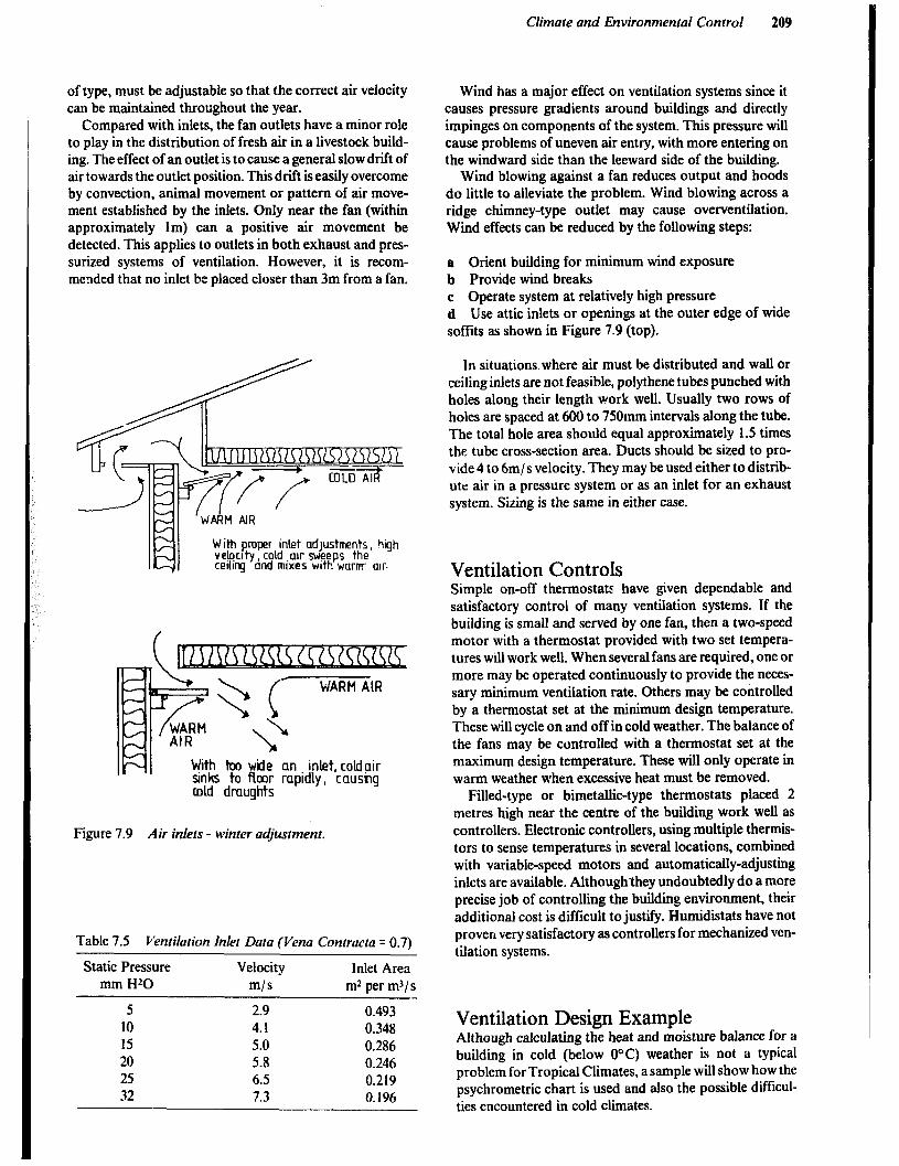
Climate and Environmental Control 209
of type, must be adjustable so that the correct air velocity can be maintained throughout the year.
Compared with inlets, the fan outlets have a minor role to play in the distribution of fresh air in a livestock build- ing. The effect of an outlet is to cause a general slow drift of air towards the outlet position. This drift is easily overcome by convection, animal movement or pattern of air move- ment established by the inlets. Only near the fan (within approximately lm) can a positive air movement be detected. This applies to outlets in both exhaust and pres- surized systems of ventilation. However, it is recom- mended that no inlet be placed closer than 3m from a fan.
With pmper inlet adjustments, high velscl ty , cold .alr sweeps the cehg and mixes w&h warm air.
Wind has a major effect on ventilation systems since it causes pressure gradients around buildings and directly impinges on components of the system. This pressure will cause problems of uneven air entry, with more entering on the windward side than the leeward side of the building.
Wind blowing against a fan reduces output and hoods do little to alleviate the problem. Wind blowing across a ridge chimney-type outlet may cause over-ventilation. Wind effects can be reduced by the following steps:
a Orient building for minimum wind exposure b Provide wind breaks c Operate system at relatively high pressure d Use attic inlets or openings at the outer edge of wide soffits as shown in Figure 7.9 (top).
In situations where air must be distributed and wall or ceiling inlets are not feasible, polythene tubes punched with holes along their length work well. Usually two rows of holes are spaced at 600 to 750mm intervals along the tube. The total hole area should equal approximately 1.5 times the tube cross-section area. Ducts should be sized to pro- vide 4 to 6m/ s velocity. They may be used either to distrib- ute air in a pressure system or as an inlet for an exhaust system. Sizing is the same in either case.
Ventilation Controls Simple on-off thermostats have given dependable and satisfactory control of many ventilation systems. If the building is small and served by one fan, then a two-speed motor with a thermostat provided with two set tempera- tures will work well. When several fans are required, one or more may be operated continuously to provide the neces- sary minimum ventilation rate. Others may be controlled by a thermostat set at the minimum design temperature. These will cycle on and off in cold weather. The balance of the fans may be controlled with a thermostat set at the maximum design temperature. These will only operate in warm weather when excessive heat must be removed.
Filled-type or bimetallic-type thermostats placed 2 metres high near the centre of the building work well as
Figure 7.9 Air inlets - winter adjustment. controllers. Electronic controllers, using multiple thermis- tors to sense temperatures in several locations, combined with variable-speed motors and automatically-adjusting inlets are available. Althoughthey undoubtedly do a more precise job of controlling the building environment, their additional cost is difficult to justify. Humidistats have not
Table 7.5 Ventilation Inlet Data (Vena Contracta = 0.7)
Static Pressure Velocity Inlet Area mm Hz0 m/s m* per m3/s
proven very satisfactory as controllers for mechanized ven- tilation systems.
5 2.9 0.493 10 4.1 0.348 15 5.0 0.286 20 5.8 0.246 25 6.5 0.219 32 7.3 0.196
Ventilation Design. Example Although calculating the heat and moisture balance for a building in cold (below O°C) weather is not a typical problem for Tropical Climates, asample will show how the psychrometric chart is used and also the possible difficul- ties encountered in cold climates.

210
Assume a farm has sixty 600kg cows housed in a 1Om by 4Om by 3m barn with 2Om* of windows and 12m* of doors. R values are: window 0.17, door 1.0, ceiling 2.6 and wall 2.1. The temperature and relative humidity are -10” C and 90% outside and + 12OC and 75% inside. The total heat and latent moisture production from the animals is found in Table 10.2 and is 113OW and 0.485kg/ hr per cow. From Figure 7.2, the 15OOm psychrometrid chart, -10°C and 90% equals -6kJ / kgenthalphy and 0.00 16kg/ kg specific humid- ity. Also + 12°C and 75% equals 3 1k.I enthalphy and 0,0078kg/ kg specific humidity. From the chart, the humid volume at 12’C and 75% equals 0.98m1/ kg, the value at which the fans are exhausting air. 1kJ q 113.6W.
Procedure: Heat production 60 x 1130 = 67,800W Respired moisture production 60 x 0.485 = 29.1 kg/ hr Heat loss from: Ceiling 400 x l/2.6 x 22” = 3,385W Wall (300-32) x l/2.1 x 22” = 2,808W Windows 20 1’ 110.17 x 22” = 2,588W Doors !2 ” !ll.Ox22O = 264w
Total heat loss 9,045w
Heat available for ventilation 67,800 - 9,045 58,766W Minimum air flow to remove moisture 29. I /‘(0.0078-0.0016) 4694kg/ hr
Fan capacity at minimum flow 4694 x 0.980/3600 Heat removed by air flow 4694 x (31.5+6)/3.6)
1.28mJ/s
48896W
As the heat available for ventilation is greater than that actually removed by the minimum ventilation rate, the inside temperature will tend to rise or the relative humidity will fall but a cycling of additional fan capacity will main- tain the desired iemperature. it should be pointed out that although the values for moisture production in Table 10.2 include normal evaporation from feed, manure and urine, the evaporation may well run higher or lower, depending primarily on how much wet floor surface is &xpoaeci from which evaporation can take place. Greater evaporation would reduce the moisture to be removed with the m=ure.
If the heat removed by the ventilation is greater than that which is available for ventilation, a fall of inside tempera- ture will result unless the insulation of the building is improved and/or supplemental heating is installed. It should be noted that a lowrered minimum ventilation rate aimed at maintaining the temperature may cause the inside air to become saturated and result in condensation on cold surfaces such as windows.
Calculations using outside summer temperatures, e.g. 21°C would show the need for additional fan capacity to remove heat and thus maintain an acceptable temperature difference between inside and outside, e.g., 4°C.
Maximum ventilozion rate is the product of sensible heat production divided by temperature difference (inside - out- side) and isobar specific heat capacity.
The sensible heat production&, according to Table 10.2, 465W per animal at 25°C (inside temperature) and the maximum ventilation rate is thus:
60 * 465 (4 x 0.35) q 19.950ml/hr or 5.54m3/s.
Between the cold and warm weather rates, thermostats cause a cycling of fan operation that will maintain temperatures within the desired range.
cooling During high temperature periods, ventilation alone may be insufficient for maintaining satisfactory temperatures in animal buildings. The following cooling system can be effectively used in totally enclosed buildings. Other cooling techniques such as spray cooling are covered in later sections.
Evaporative Cooling The evaporative cooler operates on the simple principle of a fan drawing hot air from outside through a wet pad into the building. The hot air is cooled by evaporating water which changes sensible heat in the air to latent heat in the vapor&d moisture thus causing a temperature drop.
Air temperature reduction in buildings of as much as 1 l°C can be achieved during hot periods with low humid- ity. In humid weather, the cooling effect is considerably reduced, but the system may be suitable for the greater part of the hot season in many areas.
Commercial evaporative coolers are available in sizes varying in capacity from 1 to 95m3/ s. Since they are com- plete with built-in fans, it is essential that suitable units with correct ducting, diffuser and register sizes be selected to allow balanced air distribution in the building. Ample exhaust vents should be provided around the perimeter of the building to allow the free outlet of air. A thermostat is advisable to control the units. Where humidity control is required, LI humidistat can be added to the control circuit. Some designs incorporate a heat exchanger. In these, the air which has been cooled while passing the wet pads is used to cool other air which actually enters the building. While this results in less humid air being used for ventila- tion, the extra step causes a loss in efficiency.
An alternative to the packaged evaporative cooler can be assembled with a pad and fan system. Pads made of 50mm thick compressed “wood wool” or other suitable material are installed, usually in the long wall of the building, and exhaust fans are positioned in the opposite wall. Incoming air is cooled as it passes through the wet pads and then, after passing through the building, is exhausted by fans, Figure 7.10. For effective operation, the air velocity through the pad area should be limited to about 0.8m/s. This is accomplished with 1 to 1.5m* of pad area per/m3 and second of air flow. The cooled air leaves the pad at a relative humidity of 85 to 90% but is quickly moderated by the ambient air.

Climate and Environmental Conrrol 211
Water is spread evenly over the pads from a manifold supplied from a sump with a float-controlled water level. Recirculation of water through the pads should be at the rate of approximately 16Omf/ s for each m3/ s air flow. The actual water consumption, which is the evaporation of water into the passing air, varies with the changing condi- tions of temperature and humidity. However, as a guide, it is approximately 20% of the water recirculation rate.
Evaporative coolers, which rely on wind pressure to force air through the wet pads, are less effective since the air flow is likely to be either too low or too high most of the time. While naturally ventilated evaporative coolers will require larger pad areas, the fact that no fan or power to drive a fan is required recrmmends these designs for small scale applications in rural areas. They can usually be con- structed with local materials and be operated and main- tained by the farmer at low cost.
The value of evaporative cooling systems depends on the application and on the typical wet-bulb temperatures of the region. In areas of high humidity they work well for green- houses and potato stores, but are not satisfactory for poul- try and other animals that depend on respiration for body cooling at high tempcraturcs. Evaporative cooling is much more practical in dry regions where the air can be cooled appreciably while the humidity is stil! low enough to have little effect on animal comfort.
Figure 7.10 Evaporative cooler.
Refrigeration Meeting the tempp--’ ,.tirure requirements for storing some products may not be possible with ventilation alone or with evaporative cooltrs. If the product has sufficient value to justify mechanical -efrigeration, then nearly ideal condi- tions may be provided.
Principles of Refrigeration Most fluids can occur as either a liquid or a vapour depend- ing on pressure and temperature. The higher the pressure and the lower the temperature, the more likely that the liquid phase will occur. Whenever there is a change of phase there will be a concurrent latent heat exchange. That
is, when a liquid changes to a vapour, heat is absorbed; when a vapour changes to a liquid, heat is given off. There are several materials that happen to change state at pres- sures and temperatures which make them useful in mechanical refrigeration systems.
Refrigeration Systems A refrigeration system is comprised of four main parts:
a a compressor b a condenser c an expansion valve or other restriction in the refriger- ant line, and d an evaporator.
The components are connected together in a complete circuit in the order listed. In addition, there may be a receiver (small tank) between the condenser and the expan- sion valve. See Figure 7.11.
OUTSIDE
Figure 7.11 Refrigeration swem.
When the system is charged with a refrigerant, operating the citmpressor reduces the pressure in the evaporator and causes the refrigerant to boil, evaporate and absorb heat. This causes a drop in temperature. At the same time the compressor is pumping the evaporated vapour into the condenser at high pressure. This causes the refrigerant to condense back to a liquid while giving up heat. The temperature in the condenser will rise. The receiver serves as a reservoir for liquid refrigerant. Obviously the evapora- tor is installed in the room to be refrigerated and the condenser is !ocated where ambient air can readily absorb the heat pt,oduced. Theexpansion valve is the temperature- control mechanism for the system. If it is adjusted to further restrict the refrigerant flow, both the pressure and boiling temperature in the evaporator will drop and within the limit of the system’s capacity, the room temperature may be maintained at a lower level.
The pressure on the condenser side is determined largely by ambient conditions. If the air temperature is relatively low, the condenser discharges its heat easily at normal pressures.
However, in very hot weather or if the airflow through the condenser becomes restricted by dust or other debris,
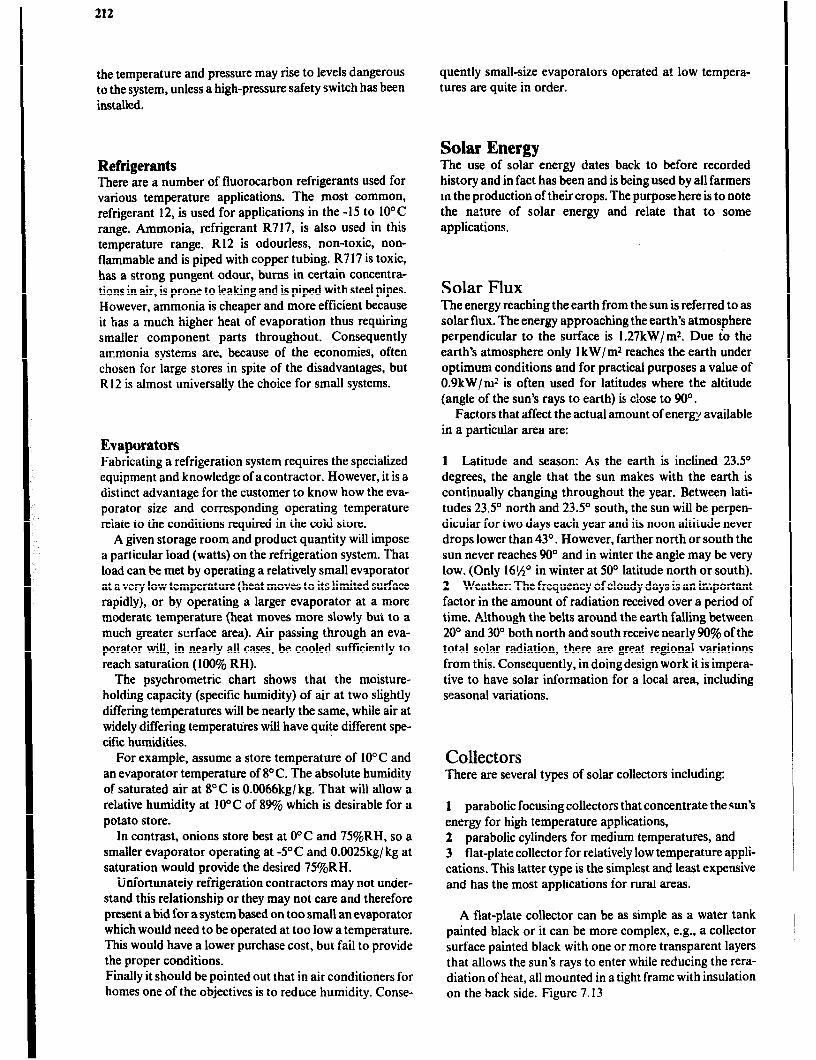
212
the temperature and pressure may rise to levels dangerous to the system, unless a high-pressure safety switch has been installed.
Refrigerants There are a number of fluorocarbon refrigerants used for various temperature applications. The most common, refrigerant 12, is used for applications in the -15 to 10” C range. Ammonia, refrigerant R717, is also used in this temperature range. R12 is odourless, non-toxic, non- flammable and is piped with copper tubing. R7 17 is toxic, has a strong pungent odour, burns in certain concentra- tions in air, is prone to leaking and is piped with steel pipes. However, ammonia is cheaper and more efficient because it has a much higher heat of evaporation thus requiring smaller component parts throughout. Consequently atrmonia systems are, because of the economies, often chosen for large stores in spite of the disadvantages, but R 12 is almost universally the choice for small systems.
Evaporators Fabricating a refrigeration system requires the specialized equipment and knowledge of acontractor. However, it is a distinct advantage for the customer to know how the eva- porator size and corresponding operating temperature relate to the conditions required in the cold store.
A given storage room and product quantity will impose a particular load (watts) on the refrigeration system. That load can be met by operating a relatively small evaporator at a very low temperature (heat moves to its limited surface rapidly), or by operating a larger evaporator at a more moderate temperature (heat moves more slowly but to a much greater surface area). Air passing through an eva- porator will, in nearly all cases, be cooled sufficiently to reach saturation (100% RH).
The psychrometric chart shows that the moisture- holding capacity (specific humidity) of air at two slightly differing temperatures will be nearly the same, while air at widely differing temperatures will have quite different spe- cific humidities.
For example, assume a store temperature of IO” C and an evaporator temperature of 8°C. The absolute humidity of saturated air at 8°C is O.O066kg/ kg. That will allow a relative humidity at 10°C of 89% which is desirable for a potato store.
In contrast, onions store best at 0“C and 75%RH, so a smaller evaporator operating at -YC and O.O025kg/ kg at saturation would provide the desired 75YcRH.
Unfortunately refrigeration contractors may not under- stand this relationship or they may not care and therefore present a bid for asystem based on too small an evaporator which would need to be operated at too low a temperature, This would have a lower purchase cost, but fail to provide the proper conditions. Finally it should be pointed out that in air conditioners for homes one of the objectives is to reduce humidity. Conse-
quently small-size evaporators operated at low tempera- tures are quite in order.
Solar Energy The use of solar energy dates back to before recorded history and in fact has been and is being used by all farmers m the production of their crops. The purpose here is to note the nature of solar energy and relate that to some applications.
Solar Flux The energy reaching the earth from the sun is referred to as solar flux. The energy approaching the earth’s atmosphere perpendicular to the surface is 1.27kW/m2. Due to the earth’s atmosphere only 1 kW/m2 reaches the earth under optimum conditions and for practical purposes a value of 0.9kW/m2 is often used for latitudes where the altitude (angle of the sun’s rays to earth) is close to 90’.
Factors that affect the actual amount of energy available in a particular area are:
1 Latitude and season: As the earth is inclined 23.5O degrees, the angle that the sun makes with the earth is continually changing throughout the year. Between lati- tudes 23.5” north and 23.5” south, the sun will be perpen- dicular for two days each year and its noon altitude never drops lower than 43O. However, farther north or south the sun never reaches 90” and in winter the angle may be very low. (Only 16%” in winter at 50’ latitude north or south). 2 Weather: The frequency of cloudy days is an important factor in the amount of radiation received over a period of time. A!though the belts around the earth falling between 20’ and 30” both north and south receive nearly 90% of the total solar radiation, there are great regional variations from this. Consequently, in doing design work it is impera- tive to have solar information for a local area, including seasonal variations.
Collectors There are several types of solar collectors including:
1 parabolic focusing collectors that concentrate the sun’s energy for high temperature applications, 2 parabolic cylinders for medium temperatures, and 3 flat-plate collector for relatively low temperature appli- cations. This latter type is the simplest and least expensive and has the most applications for rural areas.
A flat-plate collector can be as simple as a water tank painted black or it can be more complex, e.g., a collector surface painted black with one or more transparent layers that allows the sun’s rays to entet while reducing the rera- diation of heat, all mounted in a tight frame with insulation on the back side. Figure 7.13

Climate and Environmental Control 213
Table 7.6 Mean Daily Solar Radiation on a Horizontal Surface (k Wh/m2)
Place Lat. Elev. Jan. Apr.
Kenya Kericho O0 2070 6.14 5.16 Mombasa 4" 55 6.53 666 Nairobi 1” 1890 6.34 5.31
Tanzania Arusha 3!4" 700 7.24 5.14 Dar es Salaam 7O 55 5.42 3.89 Mbeya 9O 2400 4.46 4.58
Zambia Bulawayo* 20" 9.01 7.00
* Max. daily values
July Oct. Annual
4.95 3.6. - ‘0 5.46 4.45 6.28 5.84 3.72 5.47 5.24
4.81 '6.49 6.04 4.27 5.22 4.86 6.13 5.93 5.23
5.81 8.40 9.04
Figure 7.12 Mean annualsolar radiation on a horizontal surface k WhlmJ.
In most cases the heat collected is removed with either air or water. which one is used depends on the purpose of the collector. That is, to dry products, air would be used; to heat water, water would be used.
Collector plates may be made of metal with water tubes bonded to the plate. Copper has high conductivity and is easily soldered to the plate. Aluminium also has good conductivity hut is difficult to bond to the plate. Manufac- tured aluminium plates have :he water lines pressed into the surface.
Glass, fiberglass-reinforced plastic, and plastic films may be used to cover the collector. Glass passes over 90% of the solar energy; fiberglass about 80% if kept clean, and polythene film 90%. However, polythene loses a great deal of heat through reradiation. Glass has the longest life; fiberglass can be expected to last 10 years, and polythene only a year or two.
tubes painted black
g alvanised steel tray
Figure 7.13 Exploded view of typical flat-plate collector (By courtesy of Cooperative Extension Service, Cornell University).
The efficiency of collectors varies greatly. The parabolic units mentioned earlier may reach 50 to 75%. Flat-plate units operate in the range of 25 to 50% depending on design and position of mounting. Some simple designs may be even less efficient. In many cases an inexpensive, simple design is the most practical to choose. Often an increase in size will offset low efficiency. It isimportant to remember that no matter what type of collector is used or how efficient it is, it can never collect more energy than the product of the local flux rate and the collector area. In fact, it may be said that size (area) of a collector is its most important characteristic.
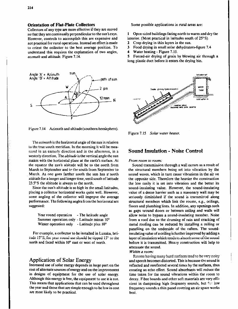
214
Orientstion of Flat-Plate Collectors Collectors of any type are more effective if they are moved so that they are continually perpendicular to the sun’s rays. However, controls to accomplish this are expensive and not practical for rural operations. Instead an effort is made to orient the collector to the best average position. To understand this requires the explanation of two angles, azrmuth and altitude. Figure 7.14.
Angle ‘A’ = Azimuth Angle ‘ET’ = Altitude
sun KY--
/ ‘&-pth ofsun
Some possible applications in rural areas are:
1 Open-sided buildings facing north to warm and dry the interior. (Most practical in latitudes south of 25”s). 2 Crop drying in thin layers in the sun. 3 Food drying in small solar dehydrators-figure 7.4 4 Water heating - Figure 7.15. 5 Forced-air drying of grain by blowing air through a long plastic duct before it enters the drying bin.
Figure 7.14 Azimuth and altitude(southern hemisphere). Figure 7.15 Solar water heater.
The azimuth is the horizontal angle of the sun in relation to the true south meridian. In the morning it will be mea- sured in an easterly direction and in the afternoon, in a westerly direction. The altitude is the vertical angle the sun makes with the horizontal plane at the earth’s surface. At the equator the sun’s altitude will be to the north from March to September and to the south from September to March. As one goes farther south the sun has a-north altitude for a longer and longer time, until south of latitude 23.5’5 the altitude is always to the north.
Since the sun’s altitude is so high in the small latitudes, placing a collector horizontal works quite well. However, some angling of the collector will imprgve the average performance. The following angles from the horizontal are suggested:
Year round operation - Tbe latitude angle Summer operation only - Latitude minus 10’ Winter operation only - Latitude plus 10”
For example, a collector to be installed in Lusaka, lati- tude 15OS, for year round use should be tipped 15” to the north and faced within lOa east or west of north.
Application of Solar Energy Increased use of solar energy depends in large part on the cost of alternate sources of energy and on the improvement in designs of equipment for the use of solar energy. Although this energy is free, the equipment to use it is not. This means that applications that can be used throughout the year and those that are simple enough to be low in cost are most likely to be practical.
Sound Insulation - Noise Control
From room to room: Sound transmission through a wall occurs as a result of
the structural members being set into vibration by the sound waves, which in turn cause vibrations in the air on the opposite side. Therefore the heavier the construction the less easily it is set into vibration and the better its sound-insulating value. Howevet, the sound-insulating value of a dense barrier such as a masonary wall may be seriously diminished if the sound is transmitted along structural members which link the rooms, e.g., ceilings, floors and plumbing lines. In addition, any openings such as gaps *around doors or between ceiling and walls will allow noise to bypass a sound-insulating member. Noise from a roof due to the druming of rain and cracking of metal roofing can be reduced by installing a ceiling or panelling on the underside of the rafters. The sound- insulating value of a ceiling is further improved by adding a layer of insulation which tends to absorb some of the sound before it is transmitted. Heavy construction will help to attenuate the sound. Within a room:
Rooms having many hard surfaces tend to be very noisy and speech becomes distorted. This is because tbe sound is reflected and rereflected several times by the surfaces, thus creating an echo effect. Sound absorbants will reduce the time taken for the sound vibrations within the room to decay. Fibre boards and other soft materials are very effi- cient in dampening high frequency sounds, but $- 10~ frequency sounds a thin panel covering an air space works best.
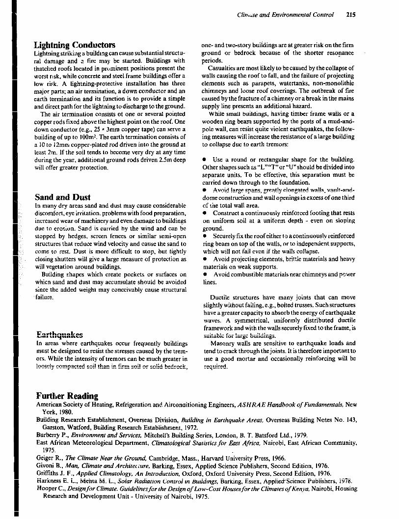
Ciin.;te and EnvironmenFal Control 215
Lightning Conductors Lightning striking a buildmg can cause substantial structu- ral damage and ;i fire may be started. Buildings with thatched roofs located in prominent positions present the worst nsk, while concrete and steel frame buildings offer a low risk. A lightning-protective installation has three major parts; an air termination, a down conductor and an earth termination and its function is to provide a simple and direct path for the light.ning to discharge to the ground.
The air termination consists of one or several pointed copper rods fixed above the highest point on the roof. One down conductor (e.g., 25 x 3mm copper tape) can serve a building of up to lOOm2. The earth termination consists of a 10 to 12mm copper-plated rod driven into the ground at least 2m. If the soil tends to become very dry at any time during the year, additional ground rods driven 2.5m deep will offer greater protection.
Sand and Dust In many dry areas sand and dust may cause considerable discomfort, eye irritation. problems with food preparation, increased wear of machinery and even damage to buildings due to erosion. Sand is carried by the wind and can be stopped by hedges, screen fences or similar semi-open structures that reduce wind velocity and cause the sand to come to rest. Dust is more difficult to stop, but tightly closing shutters will give a large measure of protection as will vegetation around buildings.
Building shapes which create pockets or surfaces on whicn sand and dust may accumulate should be avoided since the added weight may conceivably cause structural failure.
Earthquakes In areas where earthquakes occur frequently buildings must be designed to resist the stresses caused by the trem- ors. While the intensity of tremors can be much greater in loosely compacted soil than in firm soil or solid bedrock,
one- and two-story buildings are at greater risk on the firm ground or bedrock because of the shorter resonance periods.
Casualties are most likely to be caused by the collapse of walls causing the roof to fall, and the failure of projecting elements such as parapets, watertanks, non-monolithic chimneys and loose roof coverings. The outbreak of fire caused by the fracture of a chimney or a break in the mains supply line presents an additional hazard.
While small buildings, having timber frame walls or a wooden ring beam supported by the posts of a mud-and- pole wall, can resist quite violent earthquakes, the follow- ing measures will increase the resistance of a large building to collapse due to earth tremors:
0 Use a round or rectangular shape for the building. Other shapes such as”L”“T”or ‘Vshould be divided into separate units. To be effective, this separation must be carried down through to the foundation. l Avoid large spans, greatly elongated walls, vault-and- dome construction and wall openings in excess of one third of the total wall area. 0 Construct a continuously reinforced footing that rests on uniform soil at a uniform depth - even on sloping ground. 0 Securely fix the roof either to a continuously reinforced ring beam on top of the walls, or to independent supports, which will not fail even if the walls col!apse. 0 Avoid projecting elements, brittie materials and heavy materials on weak supports. 0 Avoid combustible ma!erials near chimneys and pcwer lines.
Ductile structures have many joints that can move slightly without failing, e.g., bolted trusses. Such structures have a greater capacity to absorb the energy of earthquake waves. A symmetrical, uniformly distributed ductile framework and with the walls securely fixed to the frame, is suitable for large buildings.
Masonry walls are sensitive to earthquake loads and tend t,o crack through the joints. It is therefore important to use a good mortar and occasionally reinforcing will be required.
Further Reading American Society of Heating, Refrigeration and Airconaitioning Engineers, ASHRA E Handbook of FundamenFaLF, New
York, 1980. Building Research Establishment, Overseas Division, Ruilding in Earthquake Areas, Overseas Building Notes NO. 143,
Garston, Watford, Building Research Establishment, 1972. Burberry P., Environment and Services, Mitchell’s Building Series, London, B. T. Batsford Ltd., 1979. East African Meteorological Department, Cfimatological SFaFisFics for Eosr Africa, Nairobi, East African Community,
1975. Geiger R., The Cfimare Near the Ground, Cambridge, Mass., Harvard University Press, 1966. Givoni B., Man. Climate and Architeciure, Barking, Essex, Applied Science Publishers, Second Edition, 1976. Griffiths J. F., Applied Climatology, An Introduction, Oxford, Oxford University Press, Second Edition, 1976. Harkness E. L., Mehta M. L., Solar Radiation Control in Buildings, Barking, Essex, Applied’Science Publishers, 1978. Hooper C., Designfor ClimaFe. Guidelinesfor the Design of Low-Cost Housesfor the Climares of Kenya, Nairobi, Housing
Research and Development Unit - University of Nairobi, 1975.

216
Hydrological Survey Department, Mereorological Data. Maser-u, Ministry of Works and Communica:ions, 1971. Koenigsberger 0. H., Ingersoll T. G., Mayhew A., Szokolay S. V., Manual of Tropical Housing and Building, Part I:
Climatic Design, London, Longman Group Ltd., 1973. Koenigsberger 0. H., Lynn R., Roofs in Fhe Warm Humid Troprcs. Architectural Association Paper No. 1, London, Lund
Humphries, 1965. Konya A., Design Primerfor HOF Climates, London, Architectural Press Ltd., 1980. Mather J. R., Climatology: Fundamenrais and Applicarions, New York, McGraw-Hill, 1974. Meteorological Department, CfimaFological Summaries for Zambia. Lusaka, Meteorological Depxtment, 1971. Oakley D., Tropical Houses: A Guide to their Design, London, B. T. Batsford Ltd., 1961. Olgyay V., Design :;th Climate, Bioclimatic Approach Fo ArchiFecFural Regionalism, Princeton NJ, Princeton University
Press, 1963. Olgyay V., Olgyay A., Solar Conrrol and Shading Devices, Princeton, NJ, Princeton University Press, 1976. Redding G. J., Functional Design Handbookfor Australian Farm Buildings, Melbourne, Agricultural Engineering Section,
University of Melbourne, 198 I. United Nations, Department of Economic and Social Affairs, .bw-cosF Construction Resistant lo Earthquake and
Hurricanes, New York, United Nations, 1975. Van Straaten J. F., Ther;?al Performance of Buildings, Amsterdam, Elsevier, 1967. Whitaker J. H., Agricuhural Buildings and Strucrures. Reston, Va., Reston Publishing Co., 1979.
Chapter 8
Functional Planning
The majority of African farmers are small-holders who have limited resources and income and thus a low standard of living. The primary goal for most of these farmers is to produce food for the family together with some marketable surplus that can provide the income fnr such things as children’s education and goods for personal consumption. However, as urban populations increase, the demand for commercial crop production is turning many farmers to the goal of financial profit in operating their farm busi- nesses. In any case, the farmer will want to make optimum use of his resources (land, labour, capital and fixed asset ), in order to achieve the desired results.
Functional planning is essential if this goal is to be realised. A good plan should provide an understanding of the situation and how it can be changed and thus assist the farmer to see his problems, to analyse them and to enable him to make soundly based decisions when choosing between alternative uses of his resources.
While farm management planning helps the farmer to choose the type and quantity of commodities to produce, the advice from crop and livestock production specialists is required to help him decide how to produce it in an efficient way. When an enterprise requires buildings or other struc- tures, the farm building specialist will suggest alternative designs for efficient use of resources. The best plan for the whole farm operation will result from the various disci- plines of farm planning being considered together.
The great number of small farms in most developing countries makes it impracticable to devise a plan for each farm. Instead, a few case studies that are representative of farms in the target population should be analysed to pro- duce guidelines that can be promoted among the farmers in the region by the extension service.
Similarly, the farm building engineer can produce standard designs that are directly, or with small modifica- tions, suitable for a large number of farms in an area. However, the number of case studies and designs must be sufficient to allow any farmer to be given advice that reflects his situation and which he is likely to adopt.
When plans are executed and resources invested in a farm enterprise, the resources will be tied up and unavaila- ble for alternative plans for some period of time. Since buildings are fixed assets that have a relatively long life span and consume a relatively large amount of resources for their construction, it is of special importance that they be planned for efficient and profitable use throughout their life. Planning done on paper is an inexpensive way and analyse alternatives and discuss the possibilities for satisfy- ing the objectives as established by the farmer. Once a building is erected, however, it is expensive to make changes.
Rural Planning Clearly, a plan for an individual farm is influenced by a
number of factors over which the farmer has no direct control e.g. as climate, soil fertility, government policies, state of knowledge about agricultural techniques, and value of inputs and outputs. However, since many african small-holders produce mainly for the farm household, they are only slightly affected by changes in policy and prices.
Nevertheless, national and regional rural development plans should be considered as they may provide the basis for plans for a community of farmers or an individual farm. Rural planning is carried out in the national interest to improve living conditions, balance agricultural produc- tion to demand and conserve natural resources. Many factors in the national or regional plans may directly influ- ence the choice of production at a farm and thus the requirement of buildings.
The aims of the planning strategies in rural areas are based on political decisions. They can include:
1 Provision of supportive services such as extension edu- cation, market development, processing and credit. 2 Development of infrastructure such as roads, electricity and water supplies. 3 Self-help activities to develop community facilities. 4 Increased non-farm employment opportunities.
An improved road network may, for example, make new urban markets accessible, thus making it feasible for the farmers to go into vegetable or milk production. This in turn may require housing for animals, stores for produce and feed . It would therefore be wise to investigate any plans for rural development in an area during the planning stages at an individual farm or an extension campaign promoting improved building designs in that area. Government policy is often an important factor in deter- mining the long term market trends and thus prcfitability of market production, and is therefore of special impor- tance when planning for production operations involving buildings.
Economic Planning of the Farm Operation Most textbooks on agricultural economics describe methods of economic planning for commercial farms in developed western countries, but very few deal with methods relevant to the African small-holders. Although the principles of economic theory may be relevant when reviewing African small-scale farms, their applications will undoubtedly differ from those used when reviewing com- mercial farms. Traditional applications assume, for exam- ple, that crop and livestock can be analysed separately, that the concept of farm size can be unequivocably defined, that
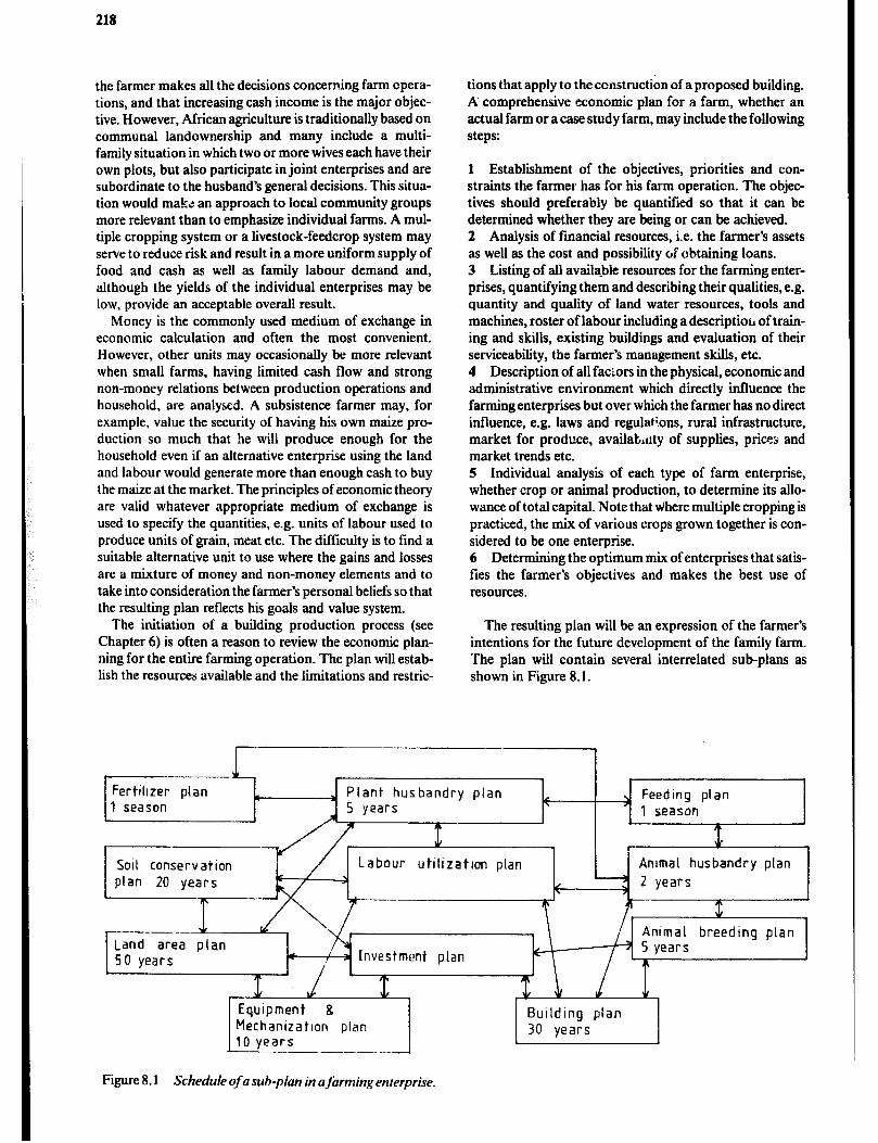
218
the farmer makes all the decisions concerning farm opera- tions, and that increasing cash income is the major objec- tive. However, African agriculture is traditionally based on. communal landownership and many include a multi- family situation in which two or more wives each have their own plots, but also participate in joint enterprises and are subordinate to the husband’s general decisions. This situa- tion would make an approach to local community groups more relevant than to emphasize individual farms. A mul- tiple cropping system or a livestock-feedcrop system may serve to reduce risk and result in a more uniform supply of food and cash as well as family labour demand and, although the yields of the individual enterprises may be low, provide an acceptable overall result.
tions that apply to the construction of a proposed building. A comprehensive economic plan for a farm, whether an actual farm or a case study farm, may include the following steps:
Money is the commonly used medium of exchange in economic calculation and often the most convenient. However, other units may occasionally be more relevant when small farms, having liited cash flow and strong non-money relations between production operations and household, are analyscd. A subsistence farmer may, for example, value the security of having his own maize pro- duction so much that he will produce enough for the household even if an alternative enterprise using the land and labour would generate more than enough cash to buy the maize at the market. The principles of economic theory are valid whatever appropriate medium of exchange is used to specify the quantities, e.g. units of labour used to produce units of grain, meat etc. The difficulty is to find a suitable alternative unit to use where the gains and losses are a mixture of money and non-money elements and to take into consideration the farmer’s personal beliefs so that the resulting plan reflects his goals and value system.
1 Establishment of the objectives, priorities and con- straints the farme; has for his farm operation. The objec- tives should preferably be quantified so that it can be determined whether they are being or can be achieved. 2 Analysis of financial resources, i.e. the farmer’s assets as well as the cost and possibility of obtaining loans. 3 Listing of all available resources for the farming enter- prises, quantifying them and describing their qualities, e.g. quantity and quality of land water resources, tools and machines, roster of labour including a description, of train- ing and skills, existing buildings and evaluation of their serviceability, the farmer’s management skills, etc. 4 Description of all factors in the physical, economic and administrative environment which directly influence the farming enterprises but over which the farmer has no direct influence, e.g. laws and regulatrons, rural infrastructure, market for produce, availat,uty of supplies, prices and market trends etc. 5 Individual analysis of each type of farm enterprise, whether crop or animal production, to determine its allo- wance of total capital. Note that Hihere multiple cropping is practiced, the mix of various crops grown together is con- sidered to be one enterprise. 6 Determining the optimum mix of enterprises that satis- fies the farmer’s objectives and makes the best use of resources.
The initiation of a building production process (see The resulting plan will be an expression of the farmer’s Chapter 6) is often a reason to review the economic plan- intentions for the future development of the family farm. ning for the entire farming operation. The plan will estab- The plan will contain several interrelated sub-plans as lish the resources available and the limitations and restric- shown in Figure 8.1.
Plant husbandry plan
SolI conservation plan 20 years
Labour utilization plan Animal husbandry plan
50 years 3 Investment plan
Equipment 8 Mechanization plan 10 years - ..-__ _-_-___
Building plan 30 years
A
Figure 8.1 Schedule of a sub-plan in ajbrming enterprise.

Funcrional Planning 219
Note that the sub-plans in Figure 8.1 may interplay in many more ways than have been illustrated. Many of these inter-relationships are of great importance when trying to maximize the result of the total production at the farm, whether the product is sold or not. Optimization of each individual enterprise may not necessarily mean that the tot& farming enterprise is optimized.
Where one is satisfied that the farmer already operate his farm according to a sound economic plan, a less ambitious approach, involving analysis of only the enterprise requir- ing a new or remodeled building and an investment apprai- sal, may suffice. A number of investment appraisal methods have been advocated for use in agriculture to give a rough indication of the merits of an investment. How- ever, small-holders generally heritate to risk cash for investmenr in fertilizer, pesticides and feed concentrate as well as improved buildings and machinery until enough food for the household is produced, a market with a cash economy is readily available and the farmer is confident in his own technical, agricultural and economic skills. Money therefore, may not always be the most relevant unit to use in the calculations.
An Approach to Building Planning Once the building requirements have been established in the economic planning, it will be the task of the farm building engineer :c, work out the functional and structural designs and deal with the farmstead plan.
The planning process always starts with a list of available resources and restrictions and other background material. The major outline for the design is then sketched. The final design is developed by working from rough sketches towards more and more detailed plans of the different parts of the building. Often however, when some internal units such as a farrowing pen has been designed and the number required established, the dimensions of the ftnai building will be influenced by the pen size and number. The farmer will often impose restrictions on the design before the planning process begins. these should be critically eval- uated and their effectiveness examined before they are accepted as part of the final design. it will be useful to discuss the extent of the proposed building and enterprise with an agricultural economist if the plan has not been based on an overa!! economic p!an.
Standard solutions, published by demonstration struc- tures and extension campaigns will, for some time future be the most important means of introducing improved building designs to small-scale farmers. However, the improved standard designs will be widely accepted by farmers, only if they are based on thorough understanding ‘of the agricultural practices and human value systems prevalent in the local farming community and are deve- loped to utilize locally available building materials and skills. New ideas, materials and construction methods should be developed and introduced to complement the strengths of the indigenous methods. Local builders, will be valuable sources of information regarding indigenous building methods and effective channels through which
innovations, can be introduced. Close cooperatic ,G between builders and farmers will help the local commun- ity to deal with its own problems and to evolve solutions from indigenous methods and local resources which will have good prospects of getting accepted.
Background Information An economic plan for the farming operation, will provide much of the background information required by the farm building engineer. As this is often missing, such informa- tion will have to be obtained by interviewing farmers and by studying similar farms in the area. Where the design is developed for a specific i~rm, priority should be given to gathering as much information as possible from that farm. All information should be critically evaluated prior to its acceptance as background material fi,>r the design of the proposed building or for a standard drawing.
In the previous section a number of factors that should be considered in developing an economic plan are listed. The farm building engineer should obtain as much of that information as possible, in addition to da:a relating to the following factors:
1 A comprehensive master plan of the farmstead. 2 For storage structures datas over expected acreage and yield of crop to be dried and stored, the length of the storage period i.e. the amount of produce to be sold or consumed at time of harvest. 3 For animal housing the quantity and quality of existing animals and the possibility and time to increase and improve the herd through a breeding programme should be considered. 4 Availability of building materials and constructions skills at the farm. 5 Laws and regulations applicable to the proposed building.
Calculations The standardized economic calculations used to determine the gross margin in a farm operation are often limited it scope and therefore a more detailed examination of the enterprise housed in the building may be of use. Knowing the expected production volume, additional data is calcu- lated using the background information.
In the case of a storage building, the expected volume of crop to be stored as well as the required handling capacity is determined. In a multi-purpose store where several dif- ferent commodities are held, a schedule of the volumes and storage periods will be useful to determine the maximum storage requirement.
Analysing the Activities Activity analysis is a tool used in planning the production in large, complex plants such as factories, large-scale grain
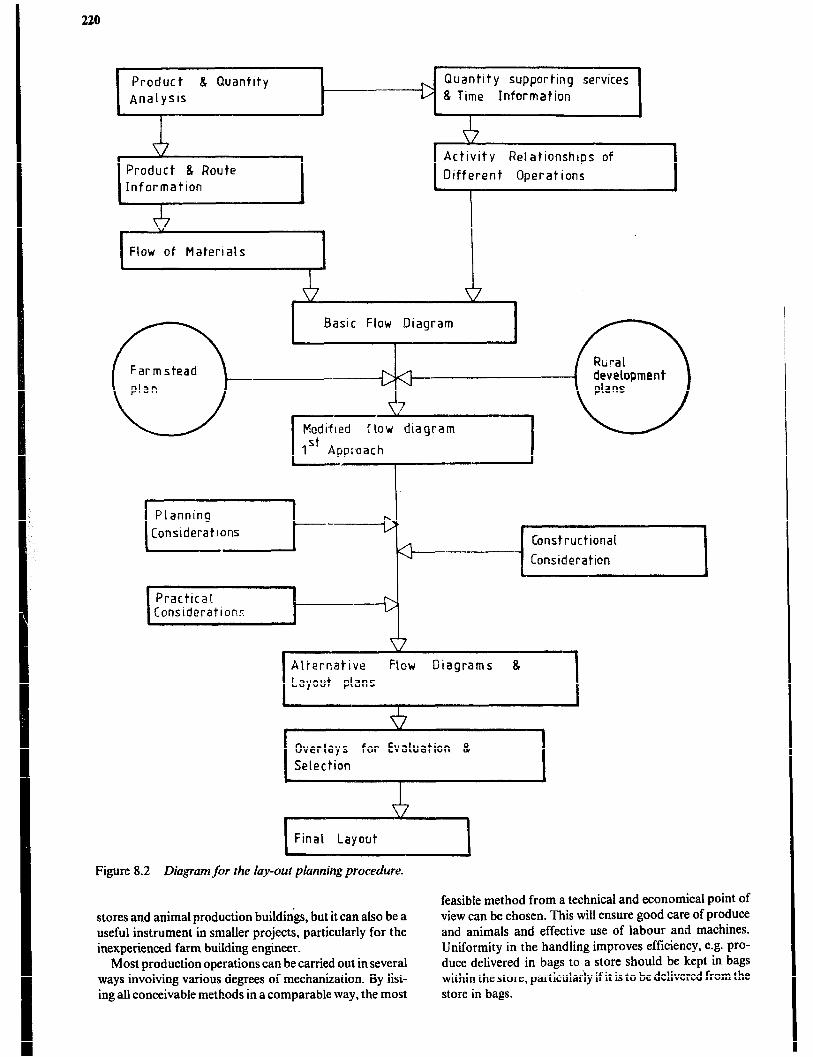
Product 8 Quantity
Analysis
9
Quantity supporting services
D 8 Time Information
Product 8 Route
Informatlon
Activity Relationships of
Different Operations
Basic Flow Diagram
Constructional
Consideration
, Practical Consideration:
4 .
v-7
Flow Diagrams 8
I
1 Final Layout ~~ 1
Figure 8.2 Diagram for the lay-out planning procedure.
feasible method from a technical and economical point of stores and animal production buildings, but it can also be a view can be chosen. This will ensure good care of produce useful instrument in smaller projects, particularly for the and animals and effective use of labour and machines. inexperienced farm building engineer. Uniformity in the handling improves efficiency, e.g. pro-
Most production operations can be carried out in several duce delivered in bags to a store should be kept in bags ways involving various degrees of mechanization. By list- within the store, particularly ifit is to be delivered from the ing all conceivable methods in a comparable way, the most store in bags.
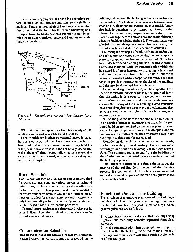
Functional Planning 221
In animal housing projects, the handling operations for feed, animals, animal produce and manure are similarly analysed. Note that the analysis of handling operations for feed produced at the farm should include harvesting and transport from the field since these operati Iris may deter- mine the most appropriate storage and handling methods inside the building.
Figure 8.3 Example of a material jlow diagram for a dairy unit.
When all handling operations have been analysed the result is summarized in a schedule of activities.
Labour efficiency is often an essential factor in small farm development. If a farmer has a reasonable standard of living, cultural norm< and social pressures may limit his willingness to invest his labour for a relatively low return. while labour efficient methods allowing for a reasonable return on the labour invested, may increase his willingness to produce a surplus.
Room Schedule This is a brief description of all rooms and spaces required for work, storage, communication, service of technical installations, etc. Because variation in yield and other pro- duction factors are to beexpected, an allowance is added to the spaces and the vo!umes. It wou!d not be uneconomical however, to allow for the most extreme variations, particu- larly if a commodity to be stored is readily marketable and can be bought back at a reasonable price later.
The total space requirement is then totaled. Also, partial sums indicate how the production operations can be divided into several houses.
Communication Schedule This describes the requirement and frequency of commun- ication between the various rooms and spaces within the
building and between the building and other structures at the farmstead. A schedule for movements between farm- stead and the fields and the market is also essential. It may also include quantities to be transported. Based on this information rooms having frequent communication can be placed close together for convenience and work efficiency when the building is being designed. The communications schedule is not always accounted for separately, but instead may be included in the schedule of activities.
Following the principle of working from the major out- line of the project towards the details, the next step is to place the proposed building on the farmstead. Some fac- tors under farmstead planning will be discussed in section Farmstead Planning. Efficient communication within the fa ,mstead is of great importance in creating a functional and harmomous operation. The schedule of functions serves as a checklist when transport is analysed. The room schedule provides information on the size of the buildings and the structural concept likely to be used.
A standard design can obviously not be shaped to lit at a specific farmstead. Nevertheless may the group of farms that the design is developed for have common features, which allow the designer to make recommendations con- cerning the placing of the new building. Some structures have special requirement as to where at the farmstead they be constructed. A maize drying crib must for example be exposed to wind.
Where the plan includes the addition of a new building to an existing farmstead, alternattve locations for the pro- posed building are sketched on the master plan or, better still on transparent paper covering the master plan, and the communication routes are indicated by arrows between the balldings, the fields and the access road.
Considering all the planning factors and requirements, one location of the proposed building is likely to have more advantages and fewer disadvantages than other altema- :ives. The transport routes to and from the building are the,1 further studied and noted for use when the interior of the building is planned.
The farmer will often have a firm opinion about the placing of the building from the start of the planning process. His opinion should be critically examined, but naturally it should be given considerable weight when the site is finally chosen.
Functional Design of the Building The sketching of alter&ive plan views of thebuilding is mainly a task of combining and coordinating the require- ments that have been analysed in earlier steps. Some general guidelines are as follows:
1 Concentrate functions and spaces that naturally belong together, but keep dirty activities separated from clean activities. 2 Make communication lines as straight and simple as possible within the building akrd to reduce the number of openings, coordinate them with those outside as shown in the farmstead plan.

222
3. Avoid unused spaces and long communication corridors. 4 Provide for simple and efficient work. Put yourself in the situation of working in the building. 5 Use as few different handling methods as possible and choose methods that are known to be reliable, flexible and simple. 6 Provide for good environment for labourers and anim- als or produce. 7 Provide for future expansion. 8 Keep the plan as simple as possible within the limits of productiGn requirerncnts.
normally includes the dwelling, animal shelters, storage structures, equipment shed, workshop and other struc- tures. A carefully organised farmstead plan should provide an arrangement of buildings and facilities that allows ade- quate space for convenient and efficient operation of all activities, while at the same time protecting the environ- ment from such undersirable effects as odours, dust, noise, flies and heavy traffic. A wide range of factors, described in section Communication Schedule, should be considered when planning the arrangement of buildings and services at the farmstead.
Finalization of Sketching After a number of sketches have been produced they are carefully analysed to select the one that best reflect the farmer’s objectives. However, because a farmer’s objectives are usclally complex and difficb,r to elicit, it is common to use more readily evaluated cruerious such as total con- structio:i cost or cash expenditure. The selected building plan is thtn drawn in its corre’ ! size, sections and eleva- tions are sketched and, where applicable, the building is positioned on the master plan. Frequently, the result of earlier steps in the planning process such as activity sche- dule or room schedule will !:ave to be reviewed and adjusted as the work progresses.
Although the immediate objective of these plans may be the inclusion of a new building in an existing farmstead, provision should be made for future expansion and replacement of buildings. In this way a poorly laid out farmstead can be improved over the long term.
Zone Planning Zone planning can be a useful tool, but it is most effective when planning a new farmstead. The farmstead is divided into zones 10 to 30 metres wide by concentric circles as shown in Figure. 8.4.
Prior to being widely promoted, standard designs are often tested at a few typical farms. The construction phase and a period of use will often give rise to useful experiences that may result in improvements of the design. Only if the designer is continuously prepared to modify the design as needed to adapt it to changing agricultural practices will it have a good chance of being successfill in the long run.
A ‘one of its kind design’intended for a specific farm can obviously not be tested in practice prior to its construction. Therefore the sketch including a cost estimate, must be presented and carefully explained to the farmer so that he understands them and feels confident that he can run an efficient and profitable production in the building. Not withstanding this, the farmer is likely to have objections and suggestions for alterations, which must be considered and worked into the final sketches. Because an understand- ing of the operation and a positive attitude by all concerned are basic requirements far efficient production, farm labourers and members of the farmer’s family who will be working in the building, should also be given an opportun- ity to review the sketches.
Prevailing wind
ROAD
I Family living area including the dwelling 2 Implement and machinery storage, farm workshop 3 Grain andfeed storage 4 Livestock buildings 5 Farm access road and courtyard
Figure 8.4 Zone planning in four zones.
Final Design When all sketches (farmstead plan, functional plan and structural concept) have been corrected, coordinated and approved by the farmer, the final building documents as described in Chapter 1 are prepared.
Farmstead Planning
Zone 1 at the centre ol’ the farmstecd 15 for family living, and should be protect:tl from odour, dust, flies, etc. In Zone 2 clean, dry and quiet activities, such as implement sheds and small storage structures can bc F!xed. In Zone3 larger grain stores, feed stores and small animal units are placed, whereas large-scale animal production is in Zone 4 and beyond.
The farmstead forms the nucleus of the farm operation The advantage of zone planning is that it provides space where a wide range of farming activities take place. It for present farm operations. future expansion and a good
Functional Planning 223
living environment. However, in many African cultures the livestock has traditionally been placed at the centre of the farmstead. Thus the zone concept Nns counter to tradition and may not be desirable.
Farmstead Planning Factors Good drainage, both surface and sub-surface, provides a dry farm courtyard and a stable foundation for buildings. A gentle slope across the site facilitates drainage, but a pronounced slope may make it difficult to site larger struc- tures without undertaking extensive earth-moving work. Adequate space should be provided to allow for maneuver- ing vehicles around the builhings and for future expansion of the farm operation.
Air movement is essential for. cross ventilation, but excessive wind can damage buildings. Since wind will carry odours and noise, livestock buildings should be placed downwind from the family living area and neighbouring homes. Undesirable winds can be diverted and reduced by nedges and trees or fences with open construction. Solar radiation may adversely affect the environment within building-. An orientation close to an east-west axis is eP:erally recommended in the tropics.
rn adequate supply of clean water is essential on any farm. When planning buildings for an expanded livestock production, the volume of the water supply must be assessed. Where applicable, the supply pipe in a good building layout will be as short as possible. Similarly, the length of electric, gas and telephone lines should be kept to a minimum.
The safety of people and animals from fire and accident hazards should be part of the planning considcrhtions. Children especially, must be protected from the many dangers at a farmstead. It is often desirable to arrange for some privacy in the family living area by screening off the garden, outdoor meeting-resting places, verandah and play area.
Measures should be taken for security from theft and vandalism. This includes an arrangement of buildings so that the farm court and the access driveway can be observed at all times, especially from the house. A neat and attractive farmstead is desirable and much can be achieved toward this end, at low cost, if the appearance is considered in the planning, and effective landscaping is utilized.
Fire Protection Measures to prevent the outbreak of fire and to limit its effect must be included in the design of buildings. Fire prevention measures include the separation of buildings to prevent tire from spreading and to permit tire-fighting, and a farm or community pond as a source of water for extin- guishing fires.
Fire Resistance in Matxials and Comtructim The ability of a building to resist fire varies widely depend-
ing upon the materials of construction and the manner in which they are used. Resistance to fire is graded according td the period of time that an element of construction is able to withstand standardized test conditions of temperature and loading.
Bare metal framework and light timber framing ext-ibit a low order of fire resistance and both types of construction fail to qualify for a grading of one-hour fire resistance, which in many countries is the lowest grade recognized. In contrast, most masonry wags have good fire-resistance ratings. Timber framing can be improved with the use of fire-retardant treatments or tire-resistant coverings such as gypsum plaster or plasterboard. Steel columns can be pro- tected with plaster or concrete coatisgb while steel roof trusses are best protected with suspended ceilings of gyp- sum plaster or plasterboard.
Classification of Fire Hazards Some types of activities and installations in farm buildings constitute special fire hazards. Wherever practical they should be isolated in a room of fireproof construction or in a separate building away from other buildings. A list of special fire hazards includes:
1 Flammable, highly combustible or explosive materials in excess of very small quantities, e.g. liquid and gas fuel, ammonium nitrate fertilizer, hay and bedding. 2 Hot-air grain drying also dust from grain handling may, in high concentrations, be explosive. 3 Furnaces and heating equipment; poultry brooder; tire places. 4 Farm workshop (especially welding) and garage for vehicles. 5 Electrical installations; continuously running mechani- cal equipment.
In addition, lightning, children playing with fire, smok- ing and lanterns are origins for outbreaks of fire. Thatched roofs are highly combustible and prone to violent fires.
Fire Separation Fire spreads mainly by wind-borne embers and by radia- tion. Buildings can be designed to resist these conditions by observing the following suggestions:
1 Adequate separation of buildings by a minimum of 6 to 8 metres, but preferably I5 to 20 metres, particularly where buildings are large or contain special fire hazards. A min- imum distance may be stated in the building code. 2 Construction using fire-resistant facing and roofing materials. 3 Avoidance of roof openings and low roof slopes, which can be more easily ignited by embers. 4 Use of tire-resistant walls which divide a large building into smaller fire compartments. To be effective, such walls must go all the way up through the building and roof and any openings in the walls must be closed by a fireproof door.

224
Evacuation and Fire Extinguishers In the event of a fire outbreak, all personnel should be able to evacuate a building within a few minutes and animals within 10 to 15 minutes. Equipment, alleys and doors should be designed to facilitate evacuation. Smoke and panic will delay evacuation during a fire, so that evacuation during a fire drill must be much faster.
In animal buildings exit doors leading to a clear passage, preferably a collecting yard, should have a minimum width of 1.5 metres for cattle and l.Om for small animals so that two animals can pass at the same time. Buildings with a floor area exceeding 2OOm2 should have at least two exit doors as widely separated as possible. The travel distance to the closest exit door should not exceed 15 metres in any part of the building,
Fire extinguisher3 of the correct type be available in all buildings and in particular where there are tire hazardous activities or materials. Water is commonly used for tire- fighting, but sand or sandy soils are effective for some types of fire. Dry powder or foam type extinguishers are best for petrol, diesel, oil and electrical fires. Regardless of type, fire extinguishers require periodic inspection to ensure their proper operation in an emergency.
Further Reading
Bushfire The dry season or any period of prolonged drought brings with it a constant fire hazard. Fanned by strong winds and intensified heatwave conditions, a large bushfire is gener- ally uncontrollable.
Firebreaks are an essential feature of rural tire protec- tion a.nd should be completed before the tire season starts. It is desirable to completely surround the homestead with major firebreaks at least 10 metres wide. Breaks can be prepared by ploughing, mowing, grazing, green cropping or, with great caution, by burning, and may include any water-course, road or other normal break which can be extended in width or length.
Shelter belts or even large trees are useful in deflecting wind-borne burning debris. For further protection, all flammable rubbish and long dry grass should be removed from the surroundings of the buildings and any openings such as windows, doors and ventilators covered with insect screens to prevent wind-borne embers from entering the building and starting a tire.
Von Blanckenburg, P., Agricultural Extemion Systems in Some African and Asian Countries, FAG Economic and Social Development Paper no. 46, Rome, Food and Agriculture Grganisation of the United Nations, 1984.
Dillon, J.I., Hardaker, B.J., Farm Mancrgement Research for Small Farmer Development, FAG Agricultural Services Bulletin, no. 41, Rome, food and Agriculture Grganisation of the United Nations, 1980.
Harwood, R.R., Small Farm Development, Understanding and Improving Farming Systems in the Humid Tropics, Boulder, Westview Press Inc., 1979.
Midwest Plan Service, Farmstead Planning Handbook, Ames, Iowa, Midwest Plan Service, 1974. Noton, N.H., Farm Buildings, Reading, College of Estate Management, 1982. Ruthemberg, H., Farming Systems in the Tropics, 3rd ed., Oxford, Oxford University Press, 1980. Swanson, B.E. (ed), Agricultural Extension, A Reference Manual, 2nd ed., Rome, Food and Agriculture Organization of
the United Nations, 1984.

Chapter 9
Crop Handling, Conditioning and Storage
Introduction Although in many parts of Africa some crops can be Froduced throughout the year, the major food crops such YS cereal grains and tubers, including potatoes, are nor- mally seasonal crops. Consequently the food produced in one harvest period, which may last for only a few weeks, must be stored for gradual consumption until the next harvest and seed must be held for the next season’s crop. In addition, in a non-controlled market, the value of any surplus crop tends to rise during this period provided that it is in a marketable condition. Therefore the principal aim in any storage system must be tci m~-intsin the crop in prime condition for as long as possible.
Crops grown for food fall into two broad categories, perishable crops and non-perishable crops. This normally refers to the rate at which a crop deteriorates after harvest and nhus the length of time it can be stored. While some crops fall clearly into one or another category, others are less well defined. For example cereal grains can be stored for over a year and are considered to be non-perishable, whereas tomatoes are perishable crops and when picked fresh, will deteriorate in days. Tubers such as potatoes, however, may be successfully stored for periods extending to several months.
Although there are methods for preserving mRay of the perishable crops such as canning, freeze drying etc., but these are normally industrialiied proc’:sszs and not found on farms. It is possible, however. to apply farm-scale methods of preservation to cereals and pulses ac:! the less perishable crops such as potatoes. To do this successfully, it is necessary to know the ways in which a crop can deteriorate and hence the methods for controlling this deterioration. Crops may need conditioning at harvest time to get them into a storable state and they may also require periodic inspection and care during the storage period. Viability of seed must be maintained and suscepti- bility to damage by fungal and insect pests must be reduced.
The storage and handiing methods should minimize losses, but must also be appropriate to other factors such as economies of scale, labour COSI and availability, building costs, and machinery cost.
Grain Drying The handlingand<torage of grains will be discussed in an orderly sequence. First the requirements for safe storage, including the principles involved in both natural and arts- cial drying, followed by drying methods suitable for the small grower as well as for the larger scale operations of cooperatives and commercial farms.
Finally, various types of storage from family size up to
commercial units will be discussed along with management suggestions for preventing damage during the storage period.
Properties of Grains Cereal grains arcs edible seeds and as such would eventually be released from the plant when fully mature. Grains can be divided into three groups; cereals (maize, wheat, millet, rice etc.), pulses’(beans, peas, cowpeas etc.), and oil seeds (soyabeans, sunflower, linseed, etc.).
Requirements for Safe Storage Crops left standing unharvested start to show diminishing quantitative and qualitative returns through shatter losses, and attacks by insects, mould, birds and rodents.
It is important therefore that harvesting is completed as soon as possible. In addition, it is necessary to remove dust and contaminants which can include insects, vegetable materials such as bits of straw and chaff, and weed seeds etc. These will fill up pore spaces within the crop and inhibit air movement and add to any possible spoilage problems. The crop must therefore be clean.
One of the most critical physiological factors in success- ful grain storage is the moisture content of the crop. High moisture content leads to storage problems since it encour- ages fungal and insect problems, respiration and germina- tion. Moisture content, however, in the growing crop is naturally high and only starts to decrease as the crop reaches maturity and the grains are drying. In a natural state, the seed would have a period of dormancy and then germinate either when re-wetted by rain, or by having a naturally high enough moisture content.
Another major factor influencing spoilage is tempera- ture. Grains are biologically active and respire during stor- age. One of the products of respiration is heat and reduc- tion of the temperature of the crop can help to reduce the rate of respiration and hence lengthen the storage life by reducing the possibility of germination. Another major temperature effect is on the activity of insect and fungal problems. With a lowering of temperature, the metabolic rate is reduced and consequently the activity causing spoilage.
A damp or warm spot in grain will increase the rate of respiration. In addition to heat, another product of respira- tion is moisture. The heat and moisture, from such a “hot spot” can spread by convection encouraging moulds and bacteria which in turn respire’ and give off more heat and moisture. It thus becomes a self-generating process. Insect activity also increases with a rise in temperature.
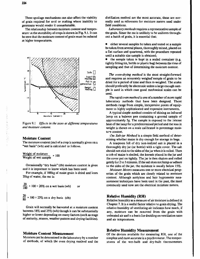
226
These spoilage mechanisms can also affect the viability of grain required for seed or malting where inability to germinate would render it unmarketable.
The relationship between moisture content and temper- ature ‘Jn the storability of crops is shown in Fig. 9.1. It can be seen that the moisture content of grain must be reduced at higher temperatures.
Figure 9.1 Effects in the store at dyferent temperatures and moisture content.
Moisture Content The moisture content (mc) of a crop is normally given on a “wet basis” (wb) and is calculated as follows;
Weight of moisture x 1oo Weight of wet sample
Occasionally “dry basis” (db) moisture content is given and it is important to know which has been used.
For example, if 1OOkg of moist grain is dried and loses 20kg of water, the mc is:
6 x 100 = 20% on a wet basis (wb) or
$ x 100 = 25% on a dry basis (db)
Grain will normally be harvested at a moisture content between 18% and 25% (wb) though it can be substantially higher or lower depending on many factors (such as stage of maturity, season, weather pattern and drying facilities).
Moisture Content Measurement Moisture can be determined in the laboratory by a number of methods, of which the oven drying method and the
distillation method are the most accurate, these are nor- mally used as references for moisture meters used under field conditions.
Laboratory methodr requires a representative sample of the grain. Since the mc is unlikely to be uniform through- out a batch of grain, it is essential that:
0 either several samples be taken and tested or a sample be taken from several places, thoroughly mixed, placed on a flat surface and quartered, with the procedure repeated until a suitable size sample is obtained; l the sample taken is kept in a sealed container (e.g. tightly fitting tin, bottle or plastic bag) between the time of sampling and that of determining the moisture content.
l?ie oven-drying method is the most straight-forward and requires an accurately weighedsample of grain to be dried for a period of time and then re-weighed. The scales should preferably be electronic unless a large enough sam- ple is used in which case good mechanical scales can be used.
The rapid oven method is one of a number of more rapid laboratory methods that have been designed. Those methods range from simple, inexpensive pieces of equip- ment to highly sophisticated and expensive instruments.
A typical simple method consists of shining an infrared lamp on a balance pan containing a ground sample of approximately 5g. The sample is exposed to the intense heat of the lamp for a predetermined period and the loss in weight is shown on a scale calibrated in percentage mois- ture content.
ihe Salt-jar Method is a simple field method of deter- mining whether maize is dry enough for storage in bags.
A teaspoon full of dry non-iodized salt is placed in a thoroughly dry jar (or bottle) with a tight cover. The salt should not stick to the sides of the jar when it is rolled. Then a cob of maize is shelled, the kernels placed in the jar and the cover put on tightly. The jar is then shaken and rolled gently for 2 to 3 minutes. If the salt does not lump or adhere to the sides of the jar, the moisture is usually below 15%.
Moisture Meters measures one or more electrical prop- erties of the gram which are closely related to moisture content. Although acetylene and hair hygrometer mea- surement techniques have been used in the past, the most commonly used now are the electrical moisture meters.
Relative Humidity (RH) Relative humidity as a measure of air moisture is defined in Chapter 7. It is a useful factor relative to grain drying. The relative humidity of ventilating air indicates how much, if any, moisture can be removed from the grain with unheated air and is a basis for deciding on ventilation rates and air temperatures.
Relative Humidity Measurement Of the devices available for measuring RH, one of the simplest and most accurate is a psychrometer. The temper- atures of the wet-bulb and dry-bulb thermometers
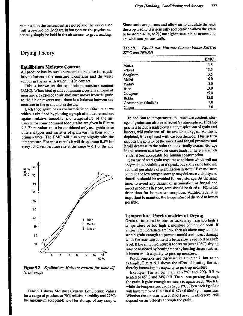
mounted on the instrument are noted and the values used with a psychrometric chart. in fan systems the psychrome- ter may simply be held in the air stream to get a reading.
Drying Theory
Equilibrium Moisture Content All produce has its own characteristic balance (or equili- brium) between the moisture it contains and the water vapour in the air with which it is in contact.
This is known as the equilibrium moisture content (EMC). When food grains containing a certain amount of moisture are exposed to air, moisture moves from the grain to the air or reverse until there is a balance between the moisture in the grain and in the air.
Each food grain has a characteristic equilibrium curve which is obtained by plotting a graph of moisture content against relative humidity and temperature of the air. Curves for some common food grains are given in Figure 9.2. These values must be considered only as a guide since different types and varieties of grain vary in their equili- brium values. The EMC will also vary slightly with the temperature. For most cereals it will drop about 0.5% for every 10°C temperature rise at the same %RH of the air.
25-C 90
a0
70
60
50
40
30
20
10
2 Maize
3 Wheat
> 6 8 10 12 14 16 18
MC%
Figure 9.2 Eqtiiiiiwium Moisture content for some dif- ferent crops
Table 9.1 shows Moisture Content Equilibrium Values for a range of produce at 70% relative humidity and 27” C, the maximum a#zceptable level for storage of any sample.
Crop Handling, Conditioning and Storage 227
Since sacks are porous and allow air to circulate through the crop readit:, it is generally acceptable to allow the grain to be stored at 1% to 2% mc higher than in bins or contain- ers with non-porous walls.
Table9.1 Eguir,. . . . ‘:h--mr Moisture Content Values EMCat 27” C and 7%12 H
_-- Maize Wheat Sorghum Millet Paddy Rice Cowpeas Beans Groundnuts (shelled) Copra
EMC
13.5 13.5 13.5 16.0 15.0 13.0 15.0 15.0 7.0 7.0
In addition to temperature and moisture content, stor- age of grains can also be affected by atmosphere. If damp grains is held in a sealed container, respiration of grain and insects, will make use of the available oxygen. As this is depleted, it is replaced with carbon dioxide. This in turn inhibits the activity of the insects and fungal problems and it will decrease to the point that it virtually ceases. Storage in thii manner can however cause taints in the grain which render it less acceptable for human consumption.
Storage of seed grain requires conditions which will not only maintain viability at it’s peak, but at the same time will avoid all possibility of germination in store. High moisture content and low oxygen storage may d&ease viability and therefore should be avoided for seed storage. At the same time, to avoid any danger of germination or fungal and insect problems in store, seed should be dried to 1% to 2% drier than for human consumption. Additionally, it is important to maintain the temperature of the seed as low as possible.
Temperature, Psychrometrics of Drying Grain to be stored in bins or sacks may have too high a temperature or too high a moisture content or both. If ambient temperatures are low, then air alone may cool the stored grain enough to prevent mould and insect damage while the moisture content is being slowly reduced to a safe level. If the air temperature is too warm (over IOOC), drying may be hastened by heating since by heating the air further, it increases it’s capacity to pick up moisture.
Psychrometrics are discussed in Chapter 7, but as an example, Figure 9.3 shows the effect of heating the air, thereby increasing its capacity to pick up moisture.
Example: The ambient air at 25°C and 70% RH is heated to 45°C and 24% RH. Then upon passing through the grain, it gains enough moisture to again reach 70% RH while the temperature drops to 3O.l”C. Then each kg of air will have removed (0.0230-0.0167) q 0.0063kg of moisture. Whether the air returns to 70% RH or some other level, will depend on air velocity through the grain.
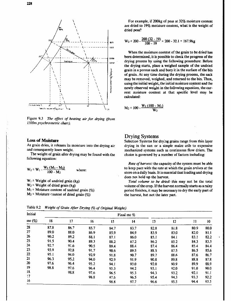
228
Figure 9.3 The effect of heating air for drying Cfrom 15OOm psychrometric chart).
Loss of Moisture As grain dries, it releases its moisture into the drying air and consequently loses weight.
The weight of grain after drying may be found with the following equation:
Wz=W,-W~(M~-M2~ IOO-Mr where:
WI = Weight of undried grain (kg) W2 = Weight of dried grain (kg) MI = Moisture content of undried grain (%) M2 = Moisture content of dried grain (%)
For example, if 200kg of peas at 32% moisture content are dried to 19% moisture content, what is the weight of dried peas?
Wz q 200 - w) q 200 - 32.1 = 167.9kg
When the moisture content of the grain to be dried has been determined, it is possible to check the progress of the drying process by using the following procedure: Before the drying starts, place a weighed sample of the undried grain in a porous sack and bury it in the surface of the bin of grain. At any time during the drying process, the sack may be removed, weighed, and returned to the bin. Then, using the initial weight, the initial moisture content and the newly observed weight in the following equation, the cur- rent moisture content at that specific level may be calculated:
M2 = 1oo WI (100 - MI) w2
Drying Systems Selection Systems for drying grains range from thin layer drying in the sun or a simple maize crib to expensive mechanized systems such as continuous flow driers. The choice is governed by a number of factors including:
Rate of harvest: the capacity of the system must be able to keep pace with the rate at which the grain arrives at the store on a daily basis. It is essential that loading and drying does not hold up the harvest.
Total volume lo be dried: this may not be the total volume of the crop. If the harvest normally starts as a rainy period finishes, it may be necessary to dry the early part of the harvest, but not the later part.
Table 9.2 Weight of Grain Afier Drying (o/o of Original Weight)
Initial Final mc %
mc (Yo) 18 17 16 15 14 13 12 11 10
28 87.8 86.7 85.7 84.7 83.7 82.8 81.8 80.9 80.0 27 89.0 88.0 86.9 85.9 84.9 83.9 83.0 82.0 81.1 26 90.2 89.2 88.1 87.1 86.0 85.1 84.1 83.1 82.2 25 91.5 90.4 89.3 88.2 87.2 86.2 85.2 84.3 83.3 24 92.7 91.6 90.5 89.4 88.4 87.4 86.4 85.4 84.4 23 93.9 92.8 91.7 90.6 89.5 88.5 87.5 86.5 85.6 22 95.1 94.0 92.9 91.8 90.7 89.7 88.6 87.6 86.7 21 96.3 95.2 94.0 92.9 91.9 90.8 89.8 88.8 87.8 20 97.6 96.4 95.2 94.1 93.0 92.0 90.9 89.9 88.9 19 98.8 97.6 96.4 95.3 94.2 93.1 92.0 91.0 90.0 18 98.8 97.6 96.5 95.3 94.3 93.2 92.1 91.1 !7 98.8 97.6 96.5 95.4 94.3 93.3 92.2 16 98.8 97.7 96.6 95.5 94.4 93.3
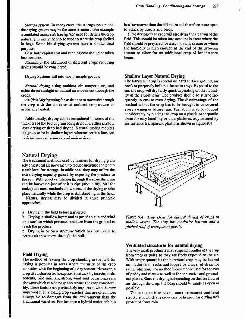
Crop Handling, Conditioning and Storage 229
Storage system: In many cases, the storage system ahd the drying system may be the same structure. For example a ventilated maize crib (see fig. 9.5) used for drying the crop naturally, is likely then to be used to store the crop shelled in bags. Some bin drying systems have a similar dual purpose.
Cost: both capital cost and running cost should be taken into account.
Flexibility: the likelihood of different crops requiring drying should be consL!ered.
Drying Systems fall into two principle groups:
Natural drying using ambient air temperature, and either direct sun!ight or natural air movement through the crops.
Artijiciaidryingusing fan assistance to move air through the crop with the air either at ambient temperature or artificially heated.
Additionally, drying can be considered in terms of the thickness of the bed of grain being dried, i.e. either shallow layer drying or deep bed drying. Natural drying requires the grain to be in shallow layers whereas certain fans can push air through grain several metres deep.
Natural Drying The traditional &et<& used by farmers for drying grain rely on natural air movement to reduce moisture content to a safe level for’storage. In additional they may utilize the extra drying capacity gained by exposing the produce to the sun. With good ventilation through the store the grain can be harvested just after it is ripe (about 30% MC for maize) but most methods allow some of the drying to take place naturally while the crop is still standing in the field.
Natural drying may be divided in three principle approaches:
a Drying in the field before harvested b Drying in shallow layers and exposed to sun and wind on a surface which prevents moisture from the ground to reach the produce. c Drying in or on a structure which has open sides to permit air movement through the bulk.
Field Drying The method of leaving the crop standing in the field for drying is pcpular in areas where maturity of the crop coincides with the beginning of a dry season. However, a crop left unharvested is exposed to attack by insects, birds, rodents, wild animals, strong wind and occasional rain showers which can damage and reduce the crop considera- bly. These factors are particularly important with the new improved high yielding crop varieties that are often more susceptible to damages from the environment than the traditional varieties. For instance a hybrid maize-cob has
less leave cover than the old maize and therefore more open to attack by insects and birds.
Field drying of the crop will also delay the clearing of the field. This should be taken into account in areas where the field should be prepared for a second rainy season or where the humidity is high enough at the end of the growing season to allow for an additional crop of for instance beans.
Shallow Layer Natural Drying The harvested crop is spread on hard surface ground, on roofs or purposely built platforms or trays. Exposed to the sun the crop will dry fairly quick depending on the humid- ity of the ambient air. The produce should be stirred fre- quently to ensure even drying. The disadvantage of the method is that the crop has to be brought in or covered every evening or before rain. The labour may be reduced considerably by placing the crop on a plastic or tarpaulin sheet for easy handling or on a platform/ tray covered by for instance transparent plastic as shown in figure 9.4
Figure 9.4 Tray Drier for natural drying of crops in shallow layers. The tray has meshwire bottom and a pitched roof of transparent plastic.
Ventilated structures for natural drying The very small producers may suspend bundles of the crop from trees or poles so they are freely exposed to the air. With larger quantities the harvested crop may be heaped on platforms or racks and topped by a layer of straw for rain protection. The method is commnrllv used for sheaves of paddy and cereals as well as for cob-maize and ground- nut plants. Since the drying is depending on the free flow of air through the crop, the heap should be made as open as possible.
The next step is to have a’more permanent ventilated structure in which the crop may be heaped for drying well protected from rain.
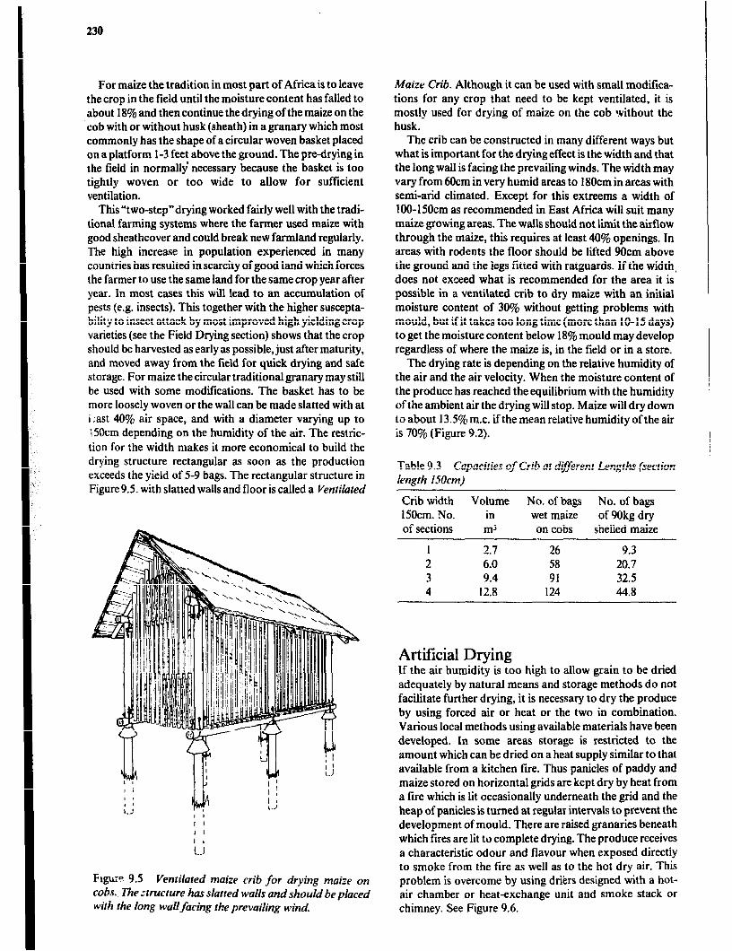
230
For maize the tradition in most part of Africa is to leave the crop in the field until the moisture content has falled to about 18% and then continue the drying of the maize on the cob with or without husk (sheath) in a granary which most commonly has the shape of a circular woven basket placed on a platform l-3 feet above the ground. The predrying in the field in normally necessary because the basket is too tightly woven or too wide to allow for sufficient ventilation.
This “two-step”drying worked fairly well with the tradi- tional farming systems where the farmer used maize with good sheathcover and could break new farmland regularly. The high increase in population experienced in many countries has resulted in scarcity of good land which forces the farmer to use the same land for the same crop year after year. In most cases this will lead to an accumulation of pests (e.g. insects). This together with the higher suscepta- bility to insect attack by most improved high yielding crop varieties (see the Field Drying section) shows that the crop should be harvested as early as possible, just after maturity, and moved away from the field for quick drying and safe storage. For maize the circular traditional granary may still be used with some modifications. The basket has to be more loosely woven or the wall can be made slatted with at i:ast 40% air space, and with a diameter varying up to l5Ocm depending on the humidity of the air. The restric- tion for the width makes it more economical to build the drying structure rectangular as soon as the production exceeds the yield of 5-9 bags. The rectangular structure in Figure 9.5. with slatted walls and floor is called a Ventilated
Frgu:? 9.5 Ventilated maize crib for drying maize on cobs., The structure has slatted walls and should be placed with the long wallfacing the prevailing wind.
Maize Crib. Although it can be used with small moditica- tions for any crop that need to be kept ventilated, it is mostly used for drying of maize on the cob without the husk.
The crib can be constructed in many different ways but what is important for the drying effect is the width and that the long wall is facing the prevailing winds. The width may vary from 6Ocm in very humid areas to 180cm in areas with semi-arid climated. Except for this extreems a width of 1 OO- 150cm as recommended in East Africa will suit many maize growing areas. The walls should not limit the airflow through the maize, this requires at least 40% openings, In areas with rodents the floor should be lifted 9Ocm above the ground and the legs fitted with ratguards. If the width. does not exceed what is recommended for the area it is possible in a ventilated crib to dry maize with an initial moisture content of -30% without getting problems with mould, but ifit takes too long time (more than lo-15 days) to get the moisture content below 18% mould may develop regardless of where the maize is, in the field or in a store.
The drying rate is depending on the relative humidity of the air and the air velocity. When the moisture content of the produce has reached the equilibrium with the humidity of the ambient air the drying will stop. Maize will dry down to about 13.5% m.c. if the mean relative humidity of the air is 70% (Figure 9.2).
Table 9.3 Capacities of Crib at drferent Lengths (section length 15Ocm)
Crib width Volume No. of bags No. of bags 15Ocm. No. in wet maize of 90kg dry of sections m3 on cobs shelled maize
1 2.7 26 9.3 2 6.0 58 20.7 3 9.4 91 32.5 4 12.8 124 44.8
Artificial Drying If the air humidity is too high to allow grain to be dried adequately by natural means and storage methods do not facilitate further drying, it is necessary to dry the produce by using forced air or heat or the two in combination. Various local methods using available materials have been developed. In some areas storage is restricted to the amount which can be dried on a heat supply similar to that available from a kitchen fire. Thus panicles of paddy and maize stored on horizontal grids are kept dry by heat from a fire which is lit occasionally underneath the grid and the heap of panicles is turned at regular intervals to prevent the development of mould. There are raised granaries beneath which fires are lit to complete drying. The produce receives a characteristic odour and flavour when exposed directly to smoke from the fire as well as to the hot dry air. This problem is overcome by using driers designed with a hot- air chamber or heat-exchange unit and smoke stack or chimney. See Figure 9.6.
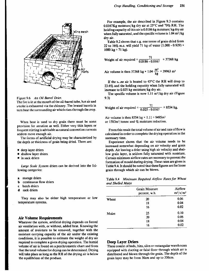
Crop Handling, Conditioning and Storage 231
I Figure 9.6 An Oil 0arrel Drier. The fire is lit at the mouth of the oil-barrel tube, hot air and smoke is exhausted via the chimney. The heated barrels in turn heat the surrounding air which rises through the crop.
When heat is used to dry grain there must be some provision for aeration as well. Either very thin layers or frequent stirring is advisable as natural convection currents seldom move enough air.
The Corms of artificial drying may be characterized by the depth or thickness of gram being dried. There are:
0 deep layer driers 0 shallow layer driers l in sack driers
Large Scale System driers can be derived into the fol- lowing categories:
a storage driers b continuous flow driers c batch driers d sack driers
They may also be either high temperature or low temperature systems.
Air Volume Requirements Whatever the system, artificial drying depends on forced air ventilation with, or without, added heat. Knowing the amount of moisture to be removed, together with the moisture carrying capacity of the air under the existing conditions, it is possible to estimate the weight of dry air required to complete a given drying operation. The humid volume of air is found on a psychrometric chart and from that the total volume for drying can be determined. Drying will take place as long as the RH of the drying air is below the equilibrium of the produce.
For example, the air described in Figure 9.3 contains 0.0167Kg moisture/ kg dry air at 25°C and ?O% RH. The holding capacity of this air is 0.0 186 kg moisture/ kg dry air when fully saturated, and the specific volume is 1.04 rnj/ kg dry air.
Table 9.2 shows that e.g. one tonne of grain dried from 22 to 16% m.c. will yield 71 kg of water (1.000 - 0.929) x 1000 kg = 71 kg).
Weightofairrequired=oo186~~o~67 = 37368 kg
m3 Air volume is then 37368 kg x 1.04 z q 39963 m3
If the sLlne air is heated to 45°C the RH will drop to 23.6% and the holding capacity when fully saturated will increase to 0.025 kg moisture/ kg dry air.
The specific volume is now 1.11 mJ/ kg dry air (Figure 9.3)
Weight of air required = o 025 -7i o167 = 8554 kg.
Air volume is then 8554 kg x 1.11 = 9495m3 or 1583mJ/ tonne and % moisture reduction.
From this result the total volume of air and rate of flow is calculated in order to complete the drying operation in the necessary time.
Experience shows that the air volume needs to be increased somewhat depending on air velocity and gram depth. Air leaving a drier using high air velocity and shal- low gram layer, is seldom fully saturated with moisture. Certain minimum airflow rates are necessary to prevent the formation of mould during drying. These rates are given in Table 9.4. It should be noted that these figures are for loose grain through which air can be blown.
Table 9.4 Minimum Required Airflow Rates for Wheat and Shelled Maize
Gram Moisture percent, w.b.
Airflow m3/s/m2
Wheat 20 0.06 18 0.04 16 0.02
Maize 25 0.10 20 0.06 18 0.04 16 0.02
Deep Layer Driers These consist of beds, bins, silos or rectangular warehouses equipped with ducting or false floor through which air is distributed and blown through the grain. The depth of the gram layer may be from 30cm and up to 350cm.

232
In deep layer driers unheated or slightly heated air (less than 6OC) is forced through the grain by a mechanical fan. The grain dries first at the point where the air enters, a drying front passes through the mass in the direction of air movement, and the grain at the air discharge location dries last. Most of the drying occurs just below the drying front in a layer called the drying zone which develops and then moves through the bulk (Figure 9.7). The depth and rate of progress of the drying zone depends largely on the damp- ness of the grain and the air speed. A low ventilation rate results in a shallow slow moving zone whilst a higher rate produces a deeper zone which progresses more quickly.
The grain furthest from the air source will remain wet, and may even become wetter (due to condensation), until the drying zone begins to move out of the crop.
For successful results, the drying zone mus! reach the surface before the grain in this area deteriorates. It is therefore normal practice to limit the depth of grain so that the drying front reaches the top in time.
Although increasing airflow increases the drying rate, it will be noted in Table 9.5 that the static pressure due to the resistance of the grain to the flow of air, rises at a very rapid rate. In general therefore, it is common prac’.ice to limit the airspeed through the crop to 0.10 - 0.15 m/s to avoid the necessity of excessive fan capacity.
Damp zone -
Drying front-i
Drying zone -
Dry zone ~
Table 9.5 Typical Resistance to Airflow (Pa)per meter of Crop Depth
crop Air speed through crop m/ -
0.05 0.10 0.15 0.20 0.25
Wheat 140 330 570 850 1070 Maize 70 180 320 500 720 Peas 50 110 190 290 410
Note: Values for the other small grain cereals. such as rice, are similar to
wheat and values for very tine seeds such as herbage seeds may exceed
2500Pa for 0. IO m/s airspeed.
Figure 9.7 Deep Layer Drying,
Air inlet
A floor drying system in a godown or warehouse type of building is shown in Figure 9.8.
main duct
Figure 9.8 Floor drying system.
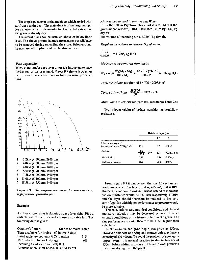
Crop Handling, Conditioning and Storage 233
The crop is piled over the lateral ducts which are fed with air from a main duct. The main duct is often large enough for a man to walk inside in order to close off laterals where the grain is already dry.
The lateral ducts can be installed above or below floor level. The above-ground laterals are cheaper but will have to be removed during unloading the store. Below-ground laterals are left in place and can be driven over.
Air volume required to remove lkg Water: From the l5OOm Psychrometric chart it is found that the given air can remove, 0.0143 - 0.0118 = 0.0025 kg HzO/kg dry air. The volume of incoming air is I .03m3/ kg dry air.
Required air volume to remove lkg of water.
1.03 - 0.0025
= 412m3/ kg Hz0
Fan capacities When planning for deep layer driers it is important to have the fan performance in mind. Figure 9.9 shows typical fan performance curves for modern high pressure propeller fans.
Moisture to be removedfrom maize
w w = WI(MI - Mz) = 10 x 103(21-15) = 706 kg HzQ I- 2
NO-M2 loo- I5
Total air volume required 4 12 x 706 = 290824m3
Total airjlowfhour y = 4847 m3/ h
1 2.2kw 9 500mm 2900rpm 2 4.0kw $J 6OOmm 2900rpm 3 4.0kw #J 6OOmm 14OOrpm 4 5.5kw @ 900mm 14OOrpm 5 7.5kw ~1OOOmm 14OOrpm 6 ll.Okw #llOOmm 14OOrpm 7 18.5kw 9125Omm 1400rpm
Figure 9.9 Fan performance curves for some modern, high pressure, propeller fans.
Example
A village cooperative is planning a deep layer drier. Find a suitable size of the drier and choose a suitable fan. The foilowing data is given:
Quantity .of grain: 10 tonnes of maize/ batch Time available for drying 60 hours (6 days) Initial moisture content (MC) in maize 21% MC reduction for sack storage 6% Incoming air at 25’C and 50% RH Assumed exhaust air at 85% RH and 19.5OC
Minimum Air Velocity required 0.07 m/s (from Table 9.4)
Try different heights of the layer considering the airflow resistance.
Height of layer (m)
Floor area required
(density of maize 720kg/m’)
I 1.5 2
13.9 9.3 6.9m*
$y = 349 521 702m’/ h.mz
Air velocity
Airflow resistance
0.10 0.14 0.20m/ s
180 480 KKlOPa
From Figure 9.9 it can be seen that the 2.2kW fan can easily manage a 1.5m layer, that is; 4850m3/ h at 480Pa. Under the same conditions with wheat instead of maize the airflow resistance would be 330, 860 respectively 1700Pa and the layer should therefore be reduced, to lm or a centrifugal fan with higher performance to pressure would be more suitable.
The calculations assumes ideal conditions and the real moisture reduction ma!‘ be decreased because of other climatic conditions or moisture content in the grain. The fan performance should therefore be a bit higher than calculated.
In the example the grain depth was given as 150cm. However, this sort of drying and storage unit may have a capacity of 3004OOcm. To avoid the problem of spoilage in upper layers, it is normal practice to dry in batches of 150cm before adding more grain. The additional grain will then start drying from the point.
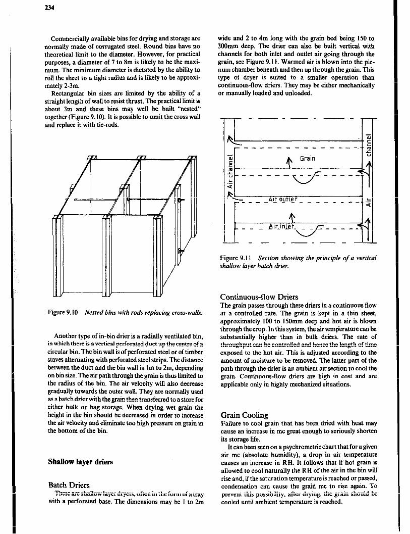
234
Commercially available bins for drying and storage are normally made of corrugated steel. Round bins have no theoretical limit to the diameter. However, for practical purposes, a diameter of 7 to 8m is likely to be the maxi- mum. The minimum diameter is dictated by the ability to roll the sheet to a tight radius and is likely to be approxi- mately 2-3m.
Rectangular bin sizes are limited by the abilit,y of a straight length of wall to resist thrust. The practical limit is about 3m and these bins may well be built “nested” together (Figure 9.10). It is possible to omit the cross wall and replace it with tie-rods.
Figure 9.10 Nested bins with roris re, placing cross-walk
Another type of in-bin drier is a radially ventilated bin, in which there is a vertical perforated duct up the centre of a circular bin. The bin wall is of perforated steel or of timber staves alternating with perforated steel strips. The distance between the duct and the bin wall is lm to 2m, depending on bin size. The air path through the grain is thus liited to the radius of the bin. The air velocity will also decrease gradually towards the outer wall. They are normally used as a batch drier with the grain then transferred to a store for either bulk or bag storage. When drying wet grain the height in the bin should be decreased in order to increase the air velocity and eliminate too high pressure on grain in the bottom of the bin.
Shallow layer driers
Batch Driers These are shallow layer dryers, often in the form of a tray
with a perforated base. The dimensions may be 1 to 2m
wide and 2 to 4m long with the grain bed being 150 to 300mm deep. The drier can also be built vertical with channels for both inlet and outlet air going through the grain, see Figure 9.11. Warmed air is blown into the ple- num chamber beneath and then up through the grain. This type of dryer is suited to a smaller operation than continuous-flow driers. They may be either mechanically or manually loaded and unloaded.
-------- I T-T
.5
. E -------a---__-,-.
2
al
E .E u------- L .-
u
fQ+!- Atr outlet L
r ------ ---_-----.,.- a ~+mi&-Q+l - - - ----- Figure 9.11 Section showing the principle of a vertical shallow layer batch drier.
Continuous-flow Driers The grain passes through these driers in a continuous flow at a controlled rate. The grain is kept in a thin sheet, approximately 100 to 150mm deep and hot air is blown through the crop. In this system, the air temfierature can be substantially higher than in bulk driers. The rate of throughput can be controlled and hence the length of time exposed to the hot air. This is adjusted according to the amount of moisture to be removed. The latter part of the path through the drier is an ambient air section to cool the grain. Continuous-flow driers are high in cost and are applicable only in highly mechanized situations.
Grain Cooling Failure to cool grain that has been dried with heat may cause an increase in mc great enough to seriously shorten its storage life.
It can been seen on a psychrometric chart that for a given air mc (absolute humidity), a drop in air temperature causes an increase in RH. It follows that if hot grain is allowed to cool naturally the RH of the air in the bin will rise and, if the saturation temperature is reached or passed, condensation can cause the graiii mc to rise again. To prevent this possibility, after drying, the grain should be cooled until ambient temperature is reached.
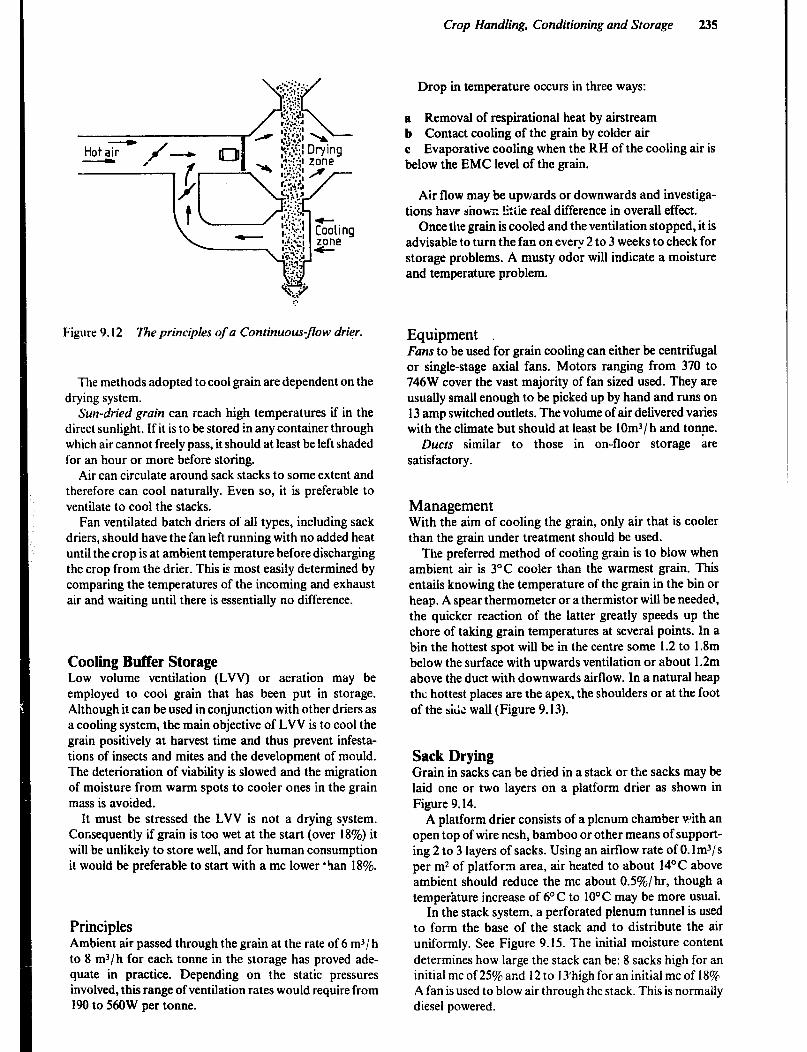
Crop Handling, Conditioning and Storage 235
Drop in temperature occurs in three ways:
a Removal of respirational heat by airstream b Contact cooling of the grain by colder air c Evaporative cooling when the KH of the cooling air is below the EMC level of the grain.
Air flow may be upwards or downwards and investiga- tions have shown litiie real difference in overall effect.
Once the grain is cooled and the ventilation stopped, it is advisable to turn the fan on every 2 to 3 weeks to check for storage problems. A musty odor will indicate a moisture and temperature problem.
Figure 9.12 The principles of a Continuous-flow drier.
The methods adopted to cool grain are dependent on the drying system.
Sun-dried grain can reach high temperatures if in the direct sunlight. If it is to be stored in any container through which air cannot freely pass, it should at least be left shaded for an hour or more before storing.
Air can circulate around sack stacks to some extent and therefore can cool naturally. Even so, it is preferable to ventilate to cool the stacks.
Fan ventilated batch driers of all types, including sack driers, should have the fan left running with no added heat until the crop is at ambient temperature before discharging the crop from the drier. This is most easily determined by comparing the temperatures of the incoming and exhaust air and waiting until there is essentially no difference.
Cooling Buffer Storage Low volume ventilation (LVV) or aeration may be employed to cool grain that has been put in storage. Although it can be used in conjunction with other driers as a cooling system, the main objective of LVV is to cool the grain positively at harvest time and thus prevent infesta- tions of insects and mites and the development of mould. The deterioration of viability is slowed and the migration of moisture from warm spots to cooler ones in the grain mass is avoided.
It must be stressed the LVV is not a drying system. Consequently if grain is too wet at the start (over 18%) it will be unlikely to store well, and for human consumption it would be preferable to start with a mc lower ‘ban 18%.
Principles Ambient air passed through the grain at the rate of 6 m-‘/h to 8 m3/h for each tonne in the storage has proved ade- quate in practice. Depending on the static pressures involved, this range of ventilation rates would require from 190 to 56OW per tonne.
Equipment Fans to be used for grain cooling can either be centrifugal or single-stage axial fans. Motors ranging from 370 to 746W cover the vast majority of fan sized used. They are usually small enough to be picked up by hand and runs on 13 amp switched outlets. The volume of air delivered varies with the climate but should at least be lOm3/ h and tonne.
Ducts similar to those in on-floor storage are satisfactory.
Management With the aim of cooling the grain, only air that is cooler than the grain under treatment should be used.
The preferred method of cooling grain is to blow when ambient air is 3°C cooler than the warmest grain. This entails knowing the temperature of the grain in the bin or heap. A spear thermometer or a thermistor will be needed, the quicker reaction of the latter greatly speeds up the chore of taking grain temperatures at several points. In a bin the hottest spot will be in the centre some 1.2 to 1.8m below the surface with upwards ventilation or about 1.2m above the duct with downwards airflow. In a natural heap the hottest places are the apex, the shoulders or at the foot of the si& wall (Figure 9.13).
Sack Drying Grain in sacks can be dried in a stack or the sacks may be laid one or two layers on a platform drier as shown in Figure 9.14.
A platform drier consists of a plenum chamber with an open top of wire nesh, bamboo or other means of support- ing 2 to 3 layers of sacks. Using an airflow rate of 0. lm3/s per m2 of platform area, air heated to about 14’C above ambient should reduce the mc about OS%/hr, though a temperature increase of 6OC to 10°C may be more usual.
In the stack system. a perforated plenum tunnel is used to form the base of the stack and to distribute the air uniformly. See Figure 9.15. The initial moisture content determines how large the stack can be: 8 sacks high for an initial mc of 25C% and 12 to 1 Ihigh for an initial mc of 180/r A fan is used to blow air through the stack. This is normally diesel powered.
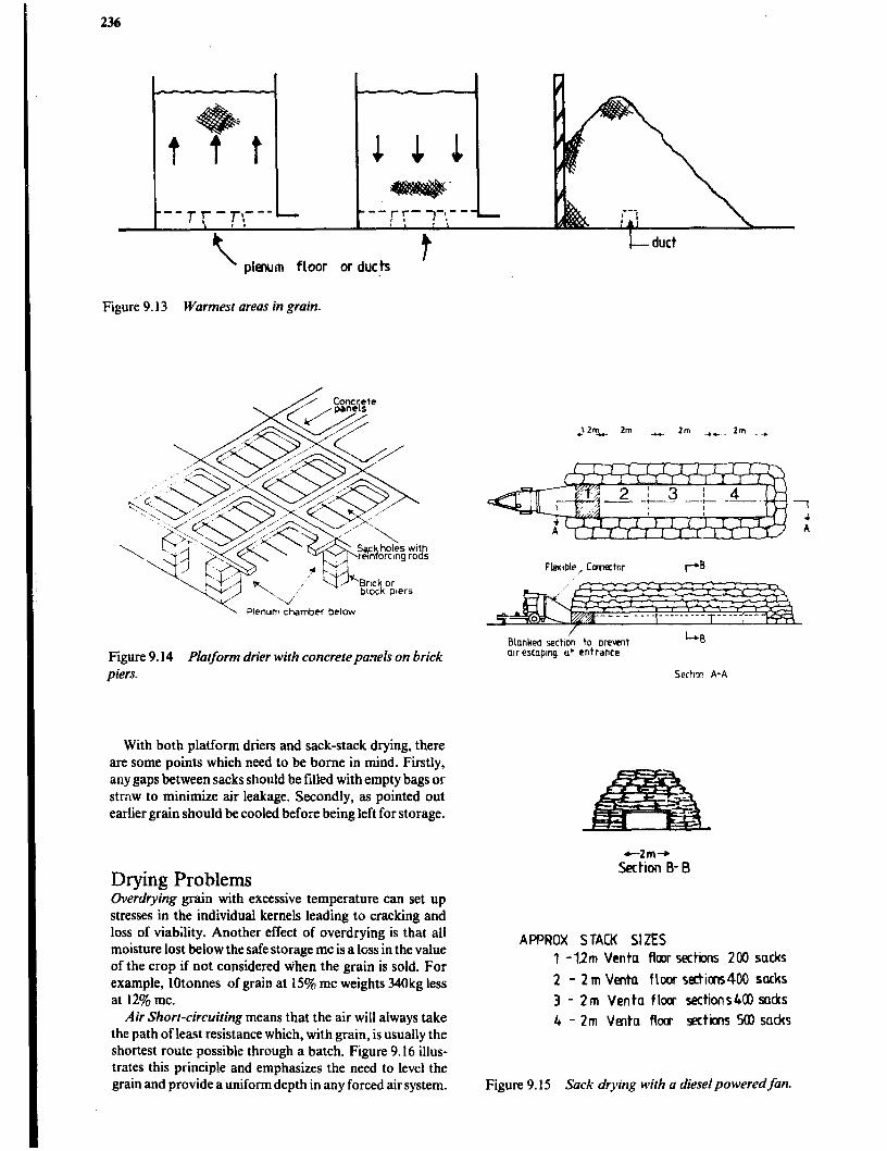
236
t t I- duct
plenum floor or ducts
Figure 9.13 Warmest areas in grain.
\ Plenum chamber betow
Bkded sechon to orevent
Figure 9.14 Platform drier with concrete paflels on brick air escaping ut entrance
piers.
With both platform driers and sack-stack drying, there are some points which need to be borne in mind. Firstly, any gaps between sacks should be filled with empty bags or straw to minimize air leakage. Secondly, as pointed out earlier grain should be cooled before being left for storage.
+-Zm+ Section B- B
Drying Problems Uverdrying grain with excessive temperature can set up stresses in the individual kernels leading to cracking and loss of viability. Another effect of overdrying is that all moisture lost below the safe storage mc is a loss in the value of the crop if not considered when the grain is sold. For example, lotonnes of gram at I594 mc weights 340kg less at 12% mc.
Air Short-circuiting means that the air will always take the path of least resistance which, with grain, is usually the shortest route possible through a batch. Figure 9.16 illus- trates this principle and emphasizes the need to level the grain and provide a uniform depth in any forced air system.
AF’PROX STACK St ZES
1 - 1.2m Vcnta floor sections 200 sacks
2 - 2m Venta floor rgtim400 sacks
3 - 2m Venta flow sections600 sacks
4 - 2m Venta flow sections SOI sad6
Figure 9.15 Sack drying with a diesel powered fan.

Crop Handling, Conditioning and Storage 237
Underdried area 7
--------- ---,,L---
Plenum
Figure 9.16 Air taking shortest path.
Dirry Crops such as grain with a large proportion of chaff, tine seeds and dirt becomes more difficult to dry as the resistance to airflow increases due to spaces between grains being blocked. Table 9.5 while dealing with clean grain, shows the great effect that small particle size has on the resistance to air flow. It is important therefore to have grain as clean and uncontaminated as possible.
Cleaning techniques range from the traditional winnow- ing of crops by throwing them into the air, to sophisticated modern high ?hroughpu: equipment. The tihro techniques used on small farms are winnowing and sieving.
Sieving is usually a two stage operation. The first sieve is just coarse enough to let the grain through while rejec- ing all larger particles. The second sieve is just fine enough to hold the grain being cleaned, but it passes weed seeds and particles that are amailer than the grain.
Crrain may sometimes have a preliminary cleaning before stor..ge to remove the majority of contaminants, and then a second more thorough cleaning before sale. This would apply in particular to seed grain.
Instruments The measuring of temperature, relative humidity, static pressure and air flow are discussed in Chapter 7. However, the special situations found,in making these measurements relative to gram drying and storage will be discussed in more detail.
Thermometers Although mercury-in-glass thermometers are fragile and rather slow acting, they are probably the most dependable
means of measuring temperature. They may be protected bi mounting in a groove in a wooden or metal probe so that temperatures deep in piles or bins may be checked. Care should be taken to allow several minutes for the temperature to stabilize.
Thermistors and thermocouples are convenient for remote measurements but they are more costly and subject to misadjustment.
Air Flow Meters Airflow meters similar to the one shown in Figure 9.17 are available to measure the vertical air speed through grain being dried in bulk. The conical clear plastic tube contains an aluminium disc which can slide on a wire mounted along the axis of the tube. A metal cone at the base of the plastic tube supports the instrument on the grain and collects the emerging air. The plastic tube is graduated in m/s and the air speed is read at the point where the disc is ‘floating’ on the air passing up the tube. In order to obtain consistent and accurate readings the disc should move freely on the wire.
For very simple and rough airflow assessment in a fan- ventilated bin, a square of light material such as a handker- chief, about 300mm square, laid on the surface of the grain should be lifted if enough air is passing through the crop.
Figure 9.17 Grain airflow meter.
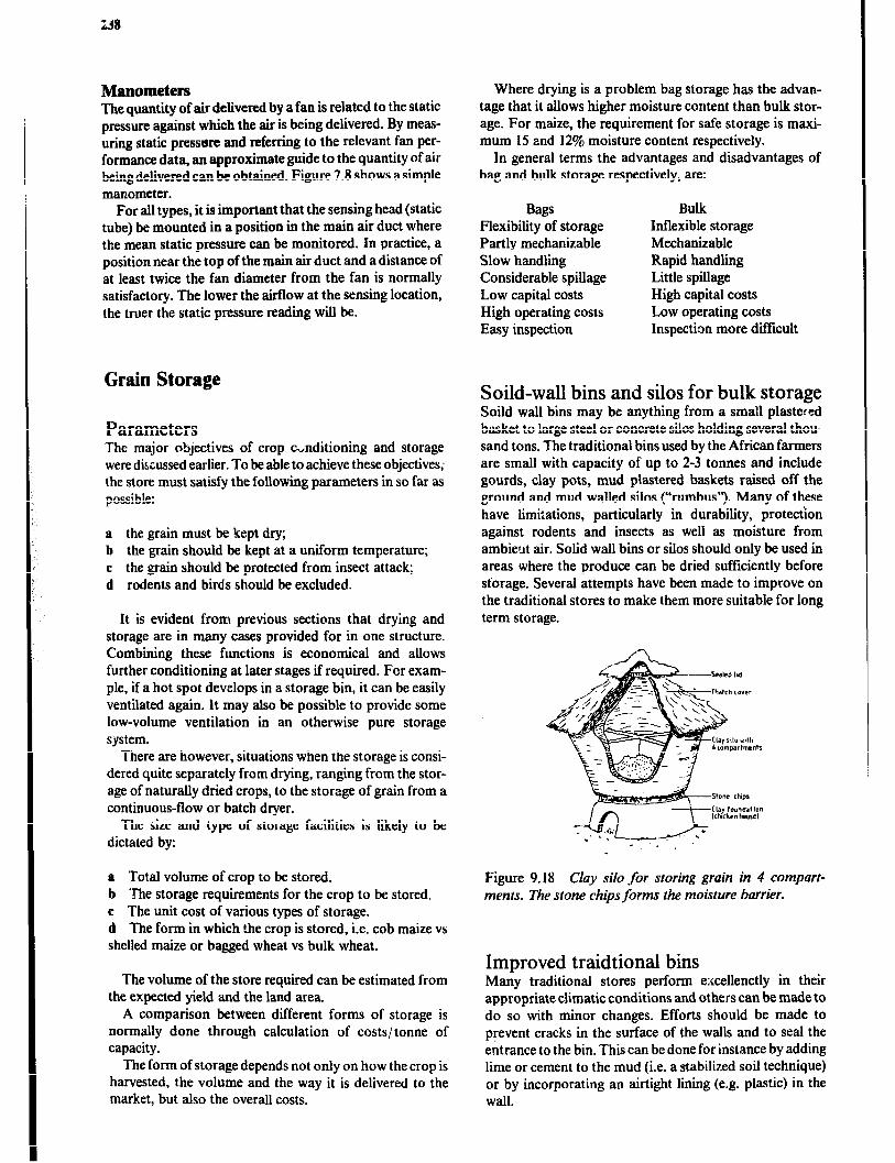
Manometers The quantity of air delivered by a fan is related to the static pressure against which the air is being delivered. By meas- uring static pressure and referring to the relevant fan per- formance data, an approximate guide to the quantity of air being delivered can be obtained. Figure 7.8 shows a simple manometer.
For all types, it is important that the sensing head (static tube) be mounted in a position in the main air duct where the mean static pressure can be monitored. In practice, a position near the top of the main air duct and a distance of at least twice the fan diameter from the fan is normally satisfactory. The lower the airfIow at the sensing location, the truer the static pressure reading will be.
Grain Storage
Parameters The major objectives of crop c,nditioning and storage were discussed earlier. To be able to achieve these objectives; the store must satisfy the following parameters in so far as possible:
a the grain must be kept dry; b the grain should be kept at a uniform temperature; c the grain should be protected from insect attack; d rodents and bird.s should be excluded.
It is evident fram previous sections that drying and storage are in many cases provided for in one structure. Combining these functions is economical and allows further conditioning at later stages if required. For exam- ple, if a hot spot develops in a storage bin, it can be easily ventilated again. It may also be possible to provide some low-volume ventilation in an otherwise pure storage system.
There are however, situations when the storage is consi- dered quite separately from drying, ranging from the stor- age of naturally dried crops, to the storage of grain from a continuous-flow or batch dryer.
The size and type of storage facilities is likely to be dictated by:
a Total volume of crop to be stored. b The storage requirements for the crop to be stored. c The unit cost of various types of storage. d The form in which the crop is stored, i.e. cob maize vs shelled maize or bagged wheat vs bulk wheat.
The volume of the store required can be estimated from the expected yield and the land area.
A comparison between different forms of storage is normally done through calculation of costs/ tonne of capacity.
The form of storage depends not only on how the crop is harvested, the volume and the way it is delivered to the market, but also the overall costs.
Where drying is a problem bag storage has the advan- tage that it allows higher moisture content than bulk stor- age. For maize, the requirement for safe storage is maxi- mum 15 and 12% moisture content respectively.
In general terms the advantages and disadvantages of bag and bulk storage respectively, are:
Bags Flexibility of storage Partly mechanizable Slow handling Considerable spillage Low capital costs High operating costs Easy inspection
Bulk Inflexible storage Mechanizable Rapid handling Little spillage High capital costs Low operating costs Inspection more difficult
Soild-wall bins and silos for bulk storage SoiId wall bins may be anything from a small plastered basket to large steel or concrete silos holding several thou- sand tons. The traditional bins used by the African farmers are small with capacity of up to 2-3 tonnes and include gourds, clay pots, mud plastered baskets raised off the ground and mud walled silos (“rumbus’?. Many of these have limitations, particularly in durability, protection against rodents and insects as well as moisture from ambier.tt air. Solid wall bins or silos should only be used in areas where the produce can be dried sufficiently before storage. Several attempts have been made to improve on the traditional stores to make them more suitable for long term storage.
+. /
Figure 9.18 Clay silo for storing grain in 4 compart- ments. The stone chips forms the moisture barrier.
Improved traidtional bins Many traditional stores perform e;<cellenctly in their appropriate climatic conditions and others can be made to do so with minor changes. Efforts should be made to prevent cracks in the surface of the walls and to seal the entrance to the bin. This can be done for instance by adding lime or cement to the mud (i.e. a stabilized soil technique) or by incorporating an airtight lining (e.g. plastic) in the wall.
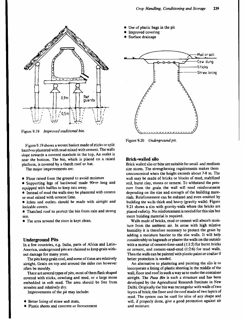
Crop Handling, Conditioning and Storage 239
Figure 9.19 Improved traditional bin.
Figure 9.19 shows a woven basket made of sticks or split bamboo plastered with mud mixed with cement. The walls slope towards a covered manhole in the top, An outlet is near the bottom. The bin, which is placed on a raised platform, is covered by a thatch roof or hat.
The major improvements are:
0 Floor raised from the ground to avoid moisture 0 Supporting legs of hardwood made 9Ocm long and equipped with baffles to keep rats away. 0 Instead of mud the walls may be plastered with cement or mud mixed with cement/lime. l Inlets and outlets should be made with airtight and lockable covers. l Thatched roof to protect the bin from rain and strong sun. 0 The area around the store is kept clean.
Underground Pits In a few countries, e.g. India, parts of Africa and Latin- America, underground pits are claimed to keep grain with- out damage for many years.
The pits keep grain cool, and some of them are relatively airtight. Grain on top and around the sides can however often be mouldy.
There arc several types of pits, most of them flask shaped covered with sticks, cowdung and mud, or a large stone embedded in soft mud. The area should be free from termites and relatively dry.
Improvements of the pit may include:
l Better lining of straw and mats, l Plastic sheets and concrete or ferrocement
l Use of plastic bags in the pit l Improved covering 0 Surface drainage
Mud or soil L
Cow dung
Sticks
Straw lining
Figure 9.20 Underground pit.
Brick-walled silo Brick walled silo or bins are suitable for small and medium size stores. The strengthening requirements makes them uneconomical when the height exceeds about 7-8 m. The wall may be made of bricks or blocks of mud, stabilized soil, burnt clay, stones or cement. To withstand the pres- sure from the grain the wall will need reinforcement depending on the size and strength of the building mate- rials. Reinforcement can be reduced and even omitted by building the walls thick and heavy (gravity walls). Figure 9.21 shows a siio with gravity-walls where the bricks are placed radiahy. No reinforcement is needed for this size but more building material is required.
Walls made of bricks, mud or cement will absorb mois- ture from the ambient air. In areas with high relative humidity it is therefore necessary to protect the grain by adding a moisture barrier to the silo walls. It will help considerably to bagwash or plaster the walls on the outside with a mortar of cement-lime-sand (1: 15) for burnt bricks or cement, and cement-sand-mud (12~6) for mud walls. Then the walls can be painted with plastic paint or coaltar if better protection is needed.
An alternative to plastering and painting the silo is to incorporate a lining of plastic sheeting in the middle of the wall, floor and roof in such a way as to make the container airtight. The ha Bin is such a structure and has been developed by the Agricultural Research Institute in New Delhi. Originally the bin was rectangular with walls of two layers of brick; the floor and the roof made of two layers of mud. The system can be used for silos of any shape and will, if properly done, give a good protection against air and moisture.

240
Figure 9.21 wail).
Silo built of bricks laid radially (gravity
34m or more may be framed by welded mesh wire and with 12mm chicken-wire tied to the outside. With bags or plastic tied to the outside it is possible to plaster the silo from the inside first and then from the outside a few days later after having removed the bags. These techniques make it possible to construct walls with thickness of 3 to 6 cm.
f: I!
ii --
Chicken wire
LID
WALL
Reinforced Concrete Silos Concrete can take very little tension and needs to be rein- forced when used for silos. Small silos suitable for farm level may be reinforced with chicken-wire
Thefirrocemenr store orferrumbu is a typical example, figure 9.22. One or two layers of 12mm chicken-wire are tied to vet-GA sticks or rods placed in a circle. The chicken- wire is then plastered from both out and inside. The verti- cals are removed after the outside istinished. Taller silos
Figure 9.22 Cross-section of a ferro-cement store dferrumbu).
Larger roncrete silos are built by using a sliding mould which is moved upwards continuously or step by step. Reinforcement and concrete are supplied from :he top Concrete silos can be made airtight if openings are properly sealed.

Crop Handling, Conditioning and Storage 241
Steel bins Steel bins ranging from properly cleaned-out steel oil- drums to commercial stores with capacity of several thou- sand tonnes figure 9.23. In most cases steel silos are more expensive than concrete silos but have the advantage of being easy to erect, and for the small sizes, also possible to move. The welded steel silo is normally airtight if the upenings are properly sealed, but even a silo assembled of corrugated iron sheets can be made air tight if all joints are sealed with rubber gaskets or bitumen.
Figure 9.23 Commercial storage silos.
Bag Storage The-most common method for grain storage in many countries is bag storage in a variety of buildings, e.g. stone, local brick, corrugated iron, and mud and wattle, with or without plastered walls and with an earth, stone, or cement floor and corrugated iron or thatched roof.
As mentioned before, the form in which the produce should be stored will depend on the quantity, harvest method, handling method, moisture content and costs.
The advantage of bag storage is listed earlier. The disad- vantage is that jutebags do not give any protection against insects which means that an insecticide has to be used. In some countries with a dry climate it is common practice to stack the bags on plinths and cover them with a tarpaulin for temporary storage. Examples are the hard stands used in Zambia and the groundnut pyramids near Kano in Northern Nigeria. However, if the grain is going to be kept for some time it is recommended to store the bags in a building. A simple store would be to use the ventilated maize crib that was used for drying, with theonly difference being that the walls should be covered as protection against rain see figure 9.24.
If the bags are stored in a multi-purpose farm shed or even in the farmers dwelling they should be kept out range from rats and mice. A raised free-standing platform equipped with ratguards will serve the purpose.
For larger quantities a special building is recommended Figure 9.25 shows a small block-built bag store (20m2) with the capacity of about 15 tonnes of cereals.
Figure 9.24 Ventilared maize cr:‘b used for storage of shelled maize in bags.
Figure 9.25 Small block-built bag store.
Whatever the size, the floor should be of good quality concrete, the door should tit tightly to prevent entry of rodents, and ventilation openings should be screened to keep out birds. The gaps between the wall and the rooimg sheets must be closed for instance with cement.
If fine mesh is used to prevent insects from coming in through the ventilation openings it must be maintained regularly; dust should be brushed away and holes repaired immediately. Figure 9.26 shotis a multi-purpose store with 90m’ (extendablej storage space suitable for co-operatives and villages.

Figure 9.26 Multipurpose store (196mz).
Storage Management Storage management is important for all types of storage. For bag-storage the four important points are:
1 Prevent damp from the floor and walls to reach the produce by stacking the bags on pallets off the ground and away from the walls.
Damp from the roof is avoided through proper ventila- tion and using damp absorbing materials. 2 Stack the bags properly to allow:
Optimal use of space Ease of sweeping the floors Ease of insepction of produce for rodents and insect Ease of counting the bags.
3 Control insects and rodents Make sure the building is rodent proof Treat the building and produce against pests Keep the warehouse clean Close all holes at doors, roof etc., where pests can enter
Repair cracks in walls where pests can hide Remove and destroy any infested residues that can contaminate newly introduced produce.
Bag stacks should be carefully constructed to maximize use of space, maintain hygienic conditions and to facilitate good management. If one lays the bags exactly on top of each other in successive layers the stack will be extremely unstable. To overcome this one must ensure that there is an overlap in each successive layer see figure 9.28.
I Figure 9.27 Proper stacking for easy management. The bags are placed on dunizage.
Insect Control l
Losses caused by insects:
a Weight loss. Insects as they develop will feed on the produce. Losses vary v:ith the c.ommodity, for grain and legumes a loss in the range of lo-30% might be expected over the storage seaEon.
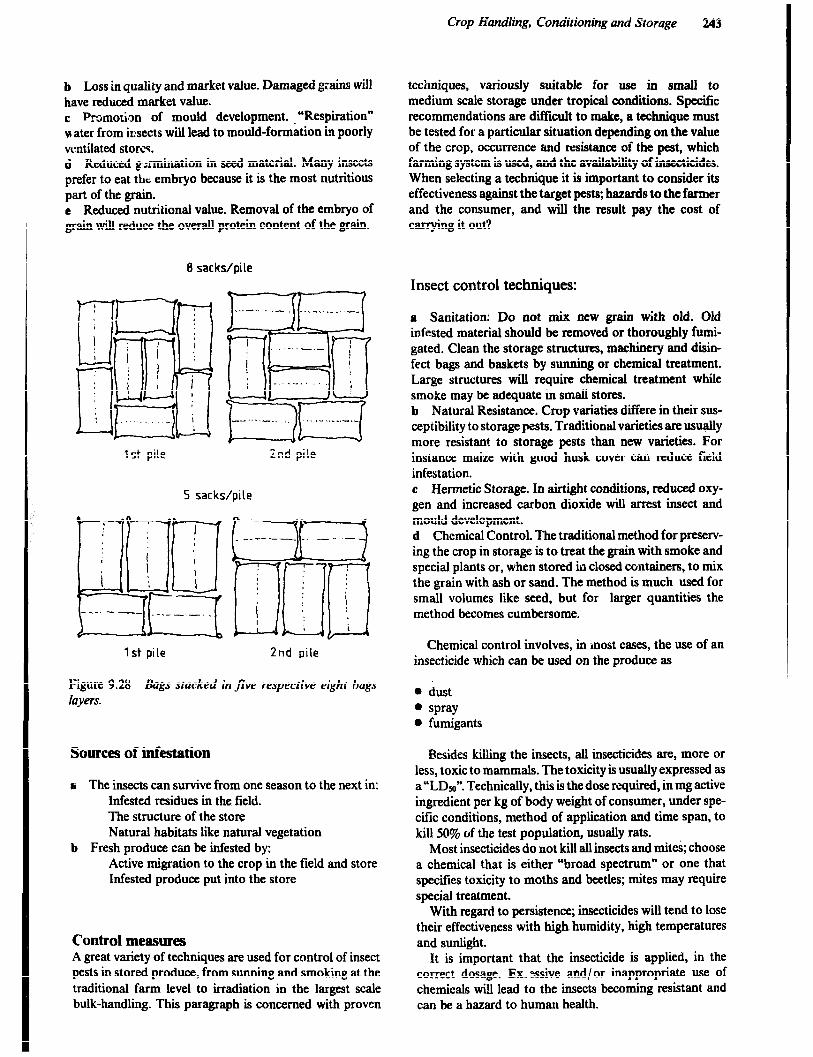
Crop Handling, Conditioning and Storage 243
b Loss in quality and market value. Damaged grains will have reduced market value. c Promotion of mould development. “Respiration” water from insects will lead to mould-formation in poorly ventilated storcq. d Reduced g:rmination in seed material. Many insects prefer to eat the embryo because it is the most nutritious part of the grain. e Reduced nutritional value. Removal of the embryo of grain will reduce the overall protein content of the grain.
8 sacks/pile
.-.-...- .- -..-...__..__
LiEid 1 ..-“-‘- I
[gjfi+ 1st pile ind pile
5 sacks/pile
1 st pile 2nd pile
Figure 9.28 Bags stacked in five respective eight bags layers.
Sources of infestation
a The insects can survive from one season to the next in: Infested residues in the field. The structure of the store Natural habitats Iike natural vegetation
b Fresh produce can be infested by: Active migration to the crop in the field and store Infested produce put into the store
Control measures A great variety of techniques are used for control of insect pests in stored produce, from sunning and smoking at the traditional farm level to irradiation in the largest scale bulk-handling. This paragraph is concerned with proven
techniques, variously suitable for use in small to medium scale storage under tropical conditions. Specific recommendations are difficult to make, a technique must be tested for a particular situation depending on the value of the crop, occurrence aud resistance of the Rest, which farming system is used, and the availability of insecticides. When selecting a technique it is important to consider its effectiveness against the target pests; hazards to the farmer and the consumer, and will the result pay the cost of carrying it out?
Insect control techniques:
a Sanitation: Do not mix new grain with old. Old infested material should be removed or thoroughly fumi- gated. Clean the storage structures, machinery and disin- fect bags and baskets by sunning or chemical treatment. Large structures wiIl require chemical treatment while smoke may be adequate in small stores. b Natural Resistance. Crop variaties differe in their sus- ceptibility to storage pests. Traditional varieties are usually more resistant to storage pests than new varieties. For instance maize with good husk cover can reduce field infestation. c Hermetic Storage. In airtight conditions, reduced oxy- gen and increased carbon dioxide will arrest insect and mould development. d Chemical Control. The traditional method for preserv- ing the crop in storage is to treat the grain with smoke and special plants or, when stored in closed containers, to mix the grain with ash or sand. The method is much used for small volumes like seed, but for larger quantities the method becomes cumbersome.
Chemical control involves, in ‘most cases, the use of an insecticide which can be used on the produce as
. dust 0 spray . fumigants
Resides kilhng the insects, all insecticides are, more or less, toxic to mammals. The toxicity is usually expressed as a “LDm”. Technically, this is the dose required, in mg active ingredient per kg of body weight of consumer, under spe- cific conditions, method of application and time span, to kill 50% of the test population, usually rats.
Most insecticides do not kill all insects and mites; choose a chemical that is either “broad spectrum” or one that specifies toxicity to moths and beetles; mites may require special treat-ment.
With regard to persistence; insecticides will tend to lose their effectiveness with high. humidity, high temperatures and sunlight.
It is important that the insecticide is applied, in the correct dosage. Ex. essive and/or inappropriate use of chemicals will lead to the insects becoming resistant and can be a hazard to human health.

244
Application:
1 Dusts are usually admixed with the grain in diluted form at 10-l 5 parts per million active ingredient (ppm Al.) at the time of loading/ bagging. Suitable chemicals: Orga- nophosphorus insecticides, pirimephos-methyl (Actellic) or pyrethroids. 2 Sprays may be added to bagged produce by spraying each layer of bags as the stack is built. This will give protection for several months but in the case of reinfesta- tion, the surface of the stack can be resprayed.
For bulk storage the sprayer maybe mounted on a belt conveyer used for loading the bin. Liquid insecticides is very suitable also for both space and surface treatment. For application a small domestic applicator (shelltox type) is sufficient for the small scale farmer, but a knapsack sprayer will reduce labour demand. The liquid form of the insecti- cides mentioned under (1) may be used. 3 Fumigation can be used for killing all pests where airtight conditions can be provided for at least 3 days for Phostoxin, or one day for Ethylene dibromide, after adding the chemical The treatment is used for closed container as well as bagged produce if covered under tar- paulin or plastic sheets. A fumigation has only an instant effect so the grain must be subsequently protected from reinfestation. Common chemicals: Phosphine gas, e.g. Phostoxin is supplied in tablets of aluminium phosphide. which release phosphine in contact with moisture in the air; ethylene dibromide, metyl bromide, carbon tetrachloride, various combinations and formulations are available e.g. as “Trogocide”, all volatile liquid fumigants; capsules and sachets are available for small scale applications and pressure<ylinders for large-scale.
Commercial insecticides usually consist of a small quan- tity of the toxic compound the “Active Ingredient*’ (AI.) with other substances called the “filler”. It is important to be able to convert from one basis to another; example: “Actellic should be applied at 15 ppm A.I.“This means we shculd apply 15 grammes of active ingredient to every million grammes of produce i.e., to one tonne.
Example
If we start with 5% dust, this means that 100 grammes of crude product (C.P.) contains only 5 gr of A.I. The dose of chemical to be applied will be
9= 15 ppm x 100
5% = 3OOgr/ tonne of produce
Rodent and Bird Control in Stores Besides consuming large quantities of stored grain and food, rodents contaminate stored produce through drop- pings, urine and hairs, and may spread human diseases. Control of rodents requires an integrated approach since no single method is completely effective. It should be focussed on creating an unfavourable environment and excluding rodents from stored grain. Methods used to
minimize the damage caused by rodents include good housekeeping, proofing, repelling, trapping and poisoning. Keeping a cat around a grain store is another effective method of control. The requirement for good house- keeping is the same for rodent as for insect control; the store should be kept clean inside and outside and easy to inspect. In the following patragraph emphasis will be on how construction can be improved to keep rodents out.
Birds are likely to be a nuisance in ware houses if no precautions are taken.
Construction Details
a Local granaries, cribs and other small stores can be made rodent-proof if the floor is raised to a minimum of 9Ocm from the ground and if the legs are equipped with conical ratguards m&de of metal sheets; see figure 9.5. b All openings between the floor and the walls should be closed. This is especially important in warehouses with walls of corrugated iron sheets. The floor should be of strong concrete to avoid rodents from coming up. c The door should tit closely to the frame and covered with sheet metal for added protection. Boards dropped vertically into slots on either side of the door, about 50cm high, will form a barrier while the door has to be kept open. d Ventilators and windows should be covered with wire mesh with openings not exceeding 12mm. This will also form a barrier against birds. e To keep birds out, other openings like the gaps between the walls and the roof should be closed or covered with wire mesh with 12mm openings and the door kept shut as much as possible. f Ideally the proofing of large central storage depots should be considered during the planning stage; then it can be incorporated at every low cost in the construction of each building. g Existing stores can in many cases be protected by means of a rodent proof fence at least 90mm high. This should be constructed of small-gauge wire netting topped by a horizontal metal sheet and should completely encircle the store. The bottom of the fence should be buried to a depth of at least 30cm
With the protective measures described above it is possi- ble to reduce and even eliminate the rodent problem if the measures are properly maintained.
Storage Management, Hygiene and Safety
Condensation and Moisture movement If bins and in particular silos are exposed to direct sunlight or if the grain inside the silo is warmer than the external air. convection currents can be started. This results in the moist

Crop Handling, Conditioning and Storage 245
air being carried through the grain and where it meets a cooler surface i.e. the silo wall, the moisture will condense out and dampen the grain in the immediate vicinic. Clearly this can be a major problem with grain stored in steel silos in hot climates, particularly in areas where the sky is clear during both day and night. A clear sky results in high drtytime temperatures and cool nights.
For small silos the problem can be reduced by covering the silo with a roof or hat that prevents the sun from heating up the surface. For larger silos other solutions have to be found, either by ventilating the grain in the store or moving the grain from one silo/cell to another. This will mix the grain enough to even out the moisture content. If the moisture content is too high it will be necessary to run the grain through a drier.
Hygiene Reference is made to what has been said about insect and rodent control for bag storage. However, it is essential that all types and sizes of grain stores the cleaning will have to be done when it is empty. If the insect population is build- ing up, the whole store may have to be fumigated or sprayed.
Table 9.6 Grain Handling Equipment
Safety Dusr is stirred up when grain is handled. Inhalation can cause respiratory problems, especktlly if exposed to slightly mouldy grain. Breathing filters shou’,a be used. Since grain dust is explosive ir is important to enforce the “No Smoking” rule and ensure that all light bulbs and electric equipment are shielded. Good ventilation is recommended.
Falls: all catwalks where a person could fall more than 150cm should have guard rails 1OOcm high and a toes board of 15cm.
Crurzs: can be formed indamp grain beneath which the grain has run out. Walking on bridged grain can cause failure of the crust, resulting in being burried and suffocated.
Machinery: all moving parts should have guards fitted and all wiring should be maintained regularly.
Grainjlowing out of a container tends to form a funnel at the centre. This highly unstable surface can stuck a man in, within seconds.
Grain Handling Equipment There us a wide variety of such equipment available on the market, and table 9.6 is an attempt to categorise their ability to move grain.
TYPe Of
Fixed
Or
Horizontal H
OF
Capacity
range
Power
Requirement
cost Advantages Dis;&antages
Equipment Portable Vertical V
Belt and
Bucket
elevator
Auger
(Screw
conveyor)
Belts
General
purpose elev;ttor with
belt or chain
with slats
Tractor
shovels
sweep
Augers
Sack
barrows
Pneumatic
F
FP
F
FP
P
FP
P
P
V
H+V
H
If belt is
ribbed max
30” angle
H
and inclined
with ribs
H
H
H
H+V
medium
to
high
medium
high
medium
medium
to
high
.
medium
depends on
distance
low
to
medium
low
medium
low
low to
medium
on tractor
- high
medium
high
medium
to
high
medium
high
medium
low
medium
high
I. efficient
2. minimum
maintenance
3. high capacity
4. cleanable
I. wide range
available
I. long distances
2. low power
3. self cleaning
1. multipurpose
2. inexpensive
I. flexible
2. high output in
short time -
for loading
lorries
I. unloading
round bins
I. flexible
I. can FL
difiicult
to erect
2. exllensive
I. zan damage
scme n .aterial
2. me&m to
heavy wear
I, expensive
2. angle very
limited
I. noisy with chain
requires space
to operate in
I. high labour
requirement
I. noisy
2. much dust
3. reduced cap for
we1 grain

246
Belt-and-Bucket Elevator Dumping Pits A flat belt is carried between a crowned pulley at the top and bottom of casing. Small buckets or scoops are fixed to the belts at regular intervals and these carry the grain from the elevator bottom to the top. The capacity depends upon width of buckets, spacing and belt speed. Elevators of up to 20m height and capacities of 50tonnes/ h are available.
To a&eve high capacity with tractors and trailers when taking grain to the store, an effective system of receiving grain must be used. Ideally, it should be possiiDle to dump a trailer load and pull away within minutes. Such a reception facility will normally be associated with an elevator to raise grain for conditioning or storage.
Auger (Screw Conveyors) Auger elevators are reasonable in cost, comparatively light in weight, and dependable in their operation. They are available in a wide range of lengths and capacities and are usually powered by an electric motor. Long augers may be mounted on wheels for easy transport. The angle of opera- tion is adjustable, however, the capacity goes down as the auger is raised, see table 9.7. High moisture content also reduces the capacity.
Table 9.7 Exampk of Auger capacity andpower requirements per 3m length of auger (0150mm)
Angle of Elevation
Moisture 0” 22.50 450 67.5" 90"
content t/hr kW t/hr kW t/hr kW t/hr kW t/hr kW
%
14 27 0.42 25 0.61 21 0.64 17 0.62 13 0.52
25 17 1.32 I5 1.40 13 1.33 10 1.08 7 0.52
Note: Auger speed 400 ‘pm
Power requirement is directly proportional to the auger length.
Flat Belt Conveyor These are used in practice horizontally although up to 15O inclination is possible. With ribs the angle can be increased to 30’. The capacity is high and loading and unloading can be done any place along the belt. It does not cause any damage to the crop and raises little dust.
Chain and Slats Conveyor These consist of a chain carrying traverse slats which drag the grain along a metal or wooden trough. Slat width up to 300mm spaced 150 to 300mm apart and chain speeds of 10 - 77 cm/s are used to give outputs up to 30 tonnes/h. Small sized models have no support frame and can be carried by two men.
Sack elevator These may be a continuous belt with ribs or a chain con- veyor with slats.
Reception Pit with an Elevator A concrete wood or steel-lined pit with an inverted pyramid or V-shaped bottom is built in the ground, see figure 9.29.
di ,Elevator
1 lnspechon 1 pit
,fcmcrete slab
Figure 9.29 Dump Pit with an auger moving thegrain to the elevator.
The crop is dumped from a trailer into the reception pit from which it flows by gravity or by the help of an auger into a second pit containing the bottom end of an elevator. Much rime is saved, if reversing to the tipping pit by the
farm transport is avoided, by having a “run-over” pit. This requires a safety grid, which must be strong enough to carry a loaded trailer.
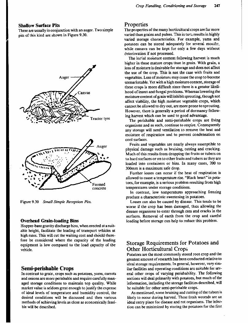
Crop Handling, Conditiqing and Storage 247
Shallow Surface Pits These are usually in conjunction with an auger. Two simple pits of this kind are shown in Figure 9.30.
Figure 9.30 Small Simple Reception Pits.
Overhead Grain-loading Bins Hopper-base gravity discharge bins, when erected at a suit- able height, facilitate the loading of transport vehicles at high rates. This will cut the waiting cost and should there- fore be considered where the capacity of the loading equipment is low compared to the load capacity of the vehicle.
Semi-perishable Crops In contrast to grain, crops such as potatoes, yams, carrots and onions are more perishable and require carefully man- aged storage conditions to maintain top quality. While market value is seldom great enough to justify the expense of ideal levels of temperature and humidity control, the desired conditions will be discussed and then various methods of achieving levels as close as economically feasi- ble will be described.
Properties The properties of the many horticultural crops are far more varied than grains and pulses. This in turr, results in highly varied storage characteristics. For example, yams and potatoes can be stored adequately for several months, while cassava can be kept for only a few days without deterioration if not processed.
The im?ial moisture content following harvest is much higher in these mature crops than in grain. With grain, a loss of moisture is desirable for storage and does not affect the use of the crop. This is not the case with fruits and vegetables. Loss of moisture may cause the crop to become unmarketable. Yet with a high moisture content, storage of these crops is more difficult since there is a greater likeli- hood of insect and fungal problems. Whereas lowering the moisture content of grain will inhibit sprouting, though not affect viability, the high .moisture vegetable crops, which cannot be allowed to dry out, are more prone to sprouting. However, there is generally a period of dormancy follow- ing harvest which can be used to good advantage.
The perishable and semi-perishable crops are living organisms and as such, continue to respire. Consequently any storage will need ventilation to remove the heat and moisture of respiration and to prevent condensation on cool surfaces.
Fruits and vegetables are nearly always susceptible to physical damage such as bruising, cutting and cracking. Much of this results from dropping the fruits or tubers on to hard surfaces or on to other fruits and tubers as they are loaded into containers or bins. In many cases, 200 to 300mm is a maximum safe drop.
Further losses can occur if the heat of respiration is allowed to cause a temperature rise. “Black heart” in pota- toes, for example, is a serious problem resulting from high temperatures under storage conditions.
In contrast, iow temperatures approaching freezing produce a characteristic sweetening in potatoes.
Losses can also be caused by disease. This tends to be worse if the crop has been damaged, thus allowing the disease organisms to enter through cuts and cracks in the surfaces. Removal of earth from the crop and careful loading before storage can help to reduce this problem.
Storage Requirements for Potatoes and Other Horticultural Crops Potatoes are the most commonly stored root crop and the greatest amount of research has been conducted relative to ideal storage requirements. In general, however, very sim- ilar facilities and operating conditions are suitable for sev- eral other crops of varying perishability. The following sections will deal primarily with potatoes, but much of the information, including the storage facilities described, will be suitable for other semi-perishable crops.
As mentioned, some bruising and cutting of the tubers is likely to occur during harvest. These fresh wounds are an ideal entry place for disease and rot organisms. The infec- tion can be minimized by storing the potatoes for the first
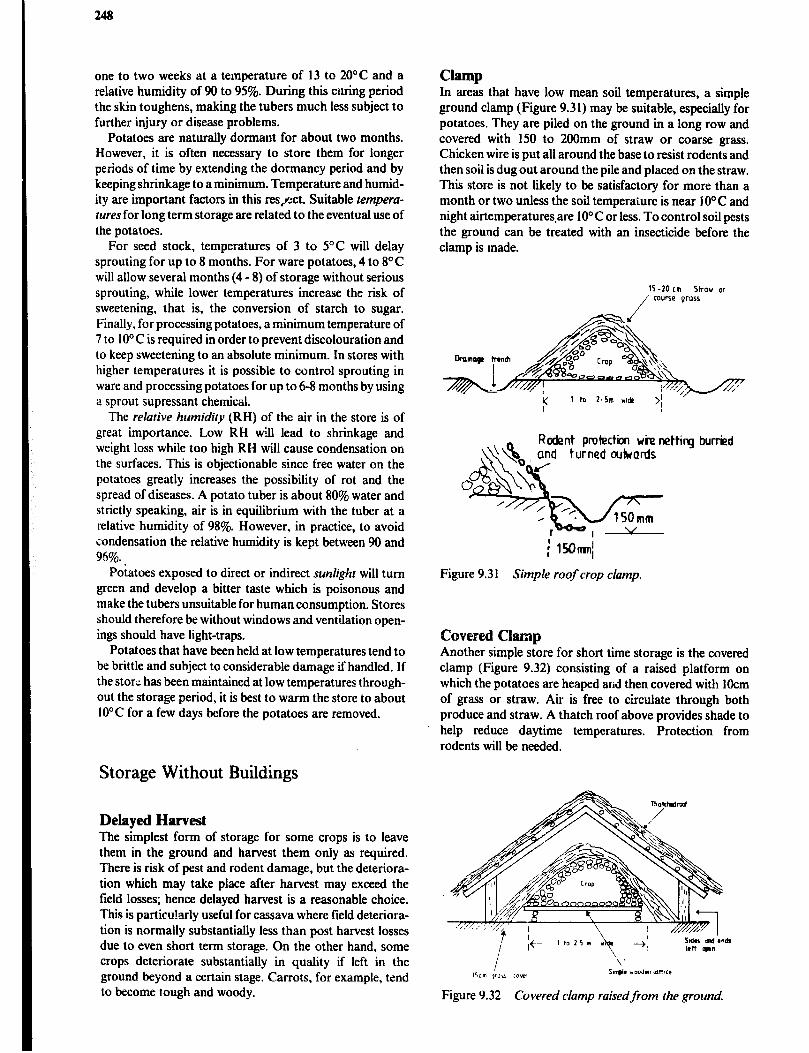
248
one to two weeks at a temperature of 13 to 20°C and a relative humidity of 90 to 95%. During this curing period the skin toughens, making the tubers much less subject to further injury or disease problems.
Potatoes are naturally dormant for about two months. However, it is often necessary to store them for longer periods of time by extending the dormancy period and by keeping shrinkage to a minimum. Temperature and humid- ity are important factors in this res/:ct. Suitable temperu- lures for long term storage are related to the eventual use of the potatoes.
For seed stock, temperatures of 3 to 5°C will delay sprouting for up to 8 months. For ware potatoes, 4 to 8’C will allow several months (4 - 8) of storage without serious sprouting, while lower temperatures increase the risk of sweetening, that is, the conversion of starch to sugar. Finally, for processing potatoes, a minimum temperature of 7 to IO” C is required in order to prevent discolouration and to keep sweetening to an absolute minimum. In stores with higher temperatures it is possible to control sprouting in ware and processing potatoes for up to 6-8 months by using a sprout supressant chemical.
The relative humidity (RH) of the air in the store is of great importance. Low RH will lead to shrinkage and weight loss while too high RH will cause condensation on the surfaces. This is objectionable since free water on the potatoes greatly increases the possibility of rot and the spread of diseases. A potato tuber is about 80% water and strictly speaking, air is in equilibrium with the tuber at a relative humidity of 98%. However, in practice, to avoid condensation the relative humidity is kept between 90 and 96%.
Potatoes exposed to direct or indirect sunlight will turn green and develop a bitter taste which is poisonous and make the tubers unsuitable for human consumption. Stores should therefore be without windows and ventilation open- ings should have light-traps.
Potatoes that have been held at low temperatures tend to be brittle and subject to considerable damage if handled. If the star;: has been maintained at low temperatures through- out the storage period, it is best to warm the store to about 10°C for a few days before the potatoes are removed.
Storage Without Buildings
Delayed Harvest The simplest form of storage for some crops is to leave them in the ground and harvest them only as required. There is risk of pest and rodent damage, but the deteriora- tion which may take place after harvest may exceed the field losses; hence delayed harvest is a reasonable choice. This is particularly useful for cassava where tield deteriora- tion is normally substantially less than post harvest losses due to even short term storage. On the other hand, some crops deteriorate substantially in quality if left in the ground beyond a certain stage. Carrots, for example, tend to become tough and woody.
Clamp In areas that have low mean soil temperatures, a simple ground clamp (Figure 9.31) may be suitable, especially for potatoes. They are piled on the ground in a long row and covered with 150 to 200mm of straw or coarse grass. Chicken wire is put all around the base to resist rodents and then soil is dug out around the pile and placed on the straw. This store is not likely to be satisfactory for more than a month or two unless the soil temperature is near IO°C and night airtemperatures.are 10°C or less. To control soil pests the ground can be treated with an insecticide before the clamp is made.
;’ 154hml~
Figure 9.3 1 Simple roof crop clamp.
buried
Covered Clamp Another simple store for short time storage is the covered clamp (Figure 9.32) consisting of a raised platform on which the potatoes are heaped and then covered with 1Ocm of grass or straw. Air is free to circulate through both produce and straw. A thatch roof above provides shade to help reduce daytime temperatures. Protection from rodents will be needed.
I lkrn *mu c0b.x Lnplr vodn hlthcc
Figure 9.32 Covered clamp raisedfrom the ground.
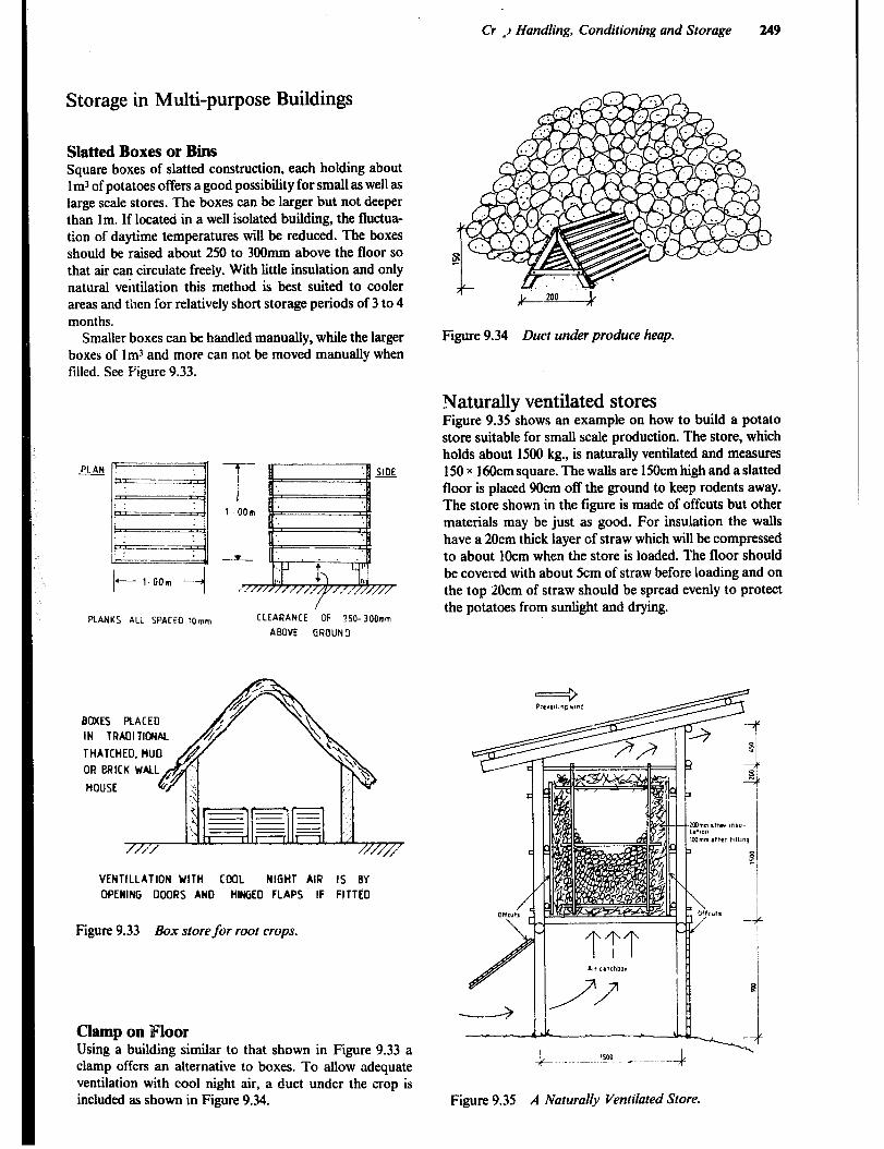
Cr . ..I Handling, Conditioning and Storage 249
Storage in Multi-purpose Buildings
Slatted Boxes or Bins Square boxes of slatted construction, each holding about lm3 of potatoes offers a good possibility for small as well as large scale stores. The boxes can be larger but not deeper than lm. If located in a well isolated building, the fluctua- tion of daytime temperatures will be reduced. The boxes should be raised about 250 to 300mm above the floor so that air can circulate freely. With little insulation and only natural ventilation this method is best suited to cooler areas and then for relatively short storage periods of 3 to 4 months.
Smaller boxes can be handled manually, while the larger boxes of lm3 and more can not be moved manually when filled. See Figure 9.33.
+-- l.OOm
PLANKS ALL SPACE0 10mm CLEARANCE OF ?50-300mm
ABOVE GROUND
BOXES PLACED
IN TRAOI TIONAL
VENTILLATION WITH COOL NIGHT AIR IS BY
OPENING DOORS AND HINGED FLAPS IF FITTEO
Figure 9.33 Box store/or root crops.
Clamp on Floor Using a building similar to that shown in Figure 9.33 a clamp offers an alternative to boxes. To allow adequate ventilation with cool night air, a duct under the crop is included as shown in Figure 9.34.
Figure 9.34 Duct under produce heap.
Naturally ventilated stores Figure 9.35 shows an example on how to build a potato store suitable for small scale production. The store, which holds about 1500 kg., is naturally ventilated and measures 150 x 16Ocm square. The walls are 150cm high and a slatted floor is placed 9Ocm off the ground to keep rodents away. The store shown in the figure is made of offcuts but other materials may be just as good. For insulation the walls have a 20cm thick layer of straw which will be compressed to about 1Ocm when the store is loaded. The floor should be covered with about 5cm of straw before loading and on the top 20cm of straw should be spread evenly to protect the potatoes from sunlight and drying.
b- ~~~ ‘sot ___. - -.-A
Figure 9.35 A Naturally Ventilated Store.

250
The method of operating the store is depending on the average temperature on the place. If the average tempera- ture is above 20°C it is necessary to extend the walls on three sides down to the ground like an apron. The forth side will have a flap that is kept open only at night in order to take advantage of the cooler air for the ventilation.
For higher altitudes with mean temperatures below 20°C it is possible to operate this potato store with contin- uous ventilation and the apron and the flap can be left out. In this case the store legs should be fitted with rat guards.
The ventilation should be just enough to remove heat caused by respiration without causing any excessive loss of moisture.
Larger Stores Buildings to store large quantities of potatoes or other root crops in bulk must be of substantial construction to resist the force of the crop against the walls. Further, the walls and ceiling must be well insulated whether outside air or refrigeration is used for cooling.
The wall sills must be securely anchored and the studs firmly fastened to the sill in order to withstand the high lateral force of the potatoes. It is desirable that the concrete floor be tied to the foundation with reinforcing bars.
Tie beams should connect the top of the side walls on opposite sides of the p&ding to resist the load and braces at frequent intervals are needed to withstand uneven loading.
Insulation and Vapour Barriers. Regardless of the climatic area in which they are built, large air cooled or refrigerated stores should be well insulated. In uplands e.g. in Southern Africa some insulation will pre- vent freezing of the potatoes in midwinter. In contrast, in hot regions where mechanical refrigeration may be neces- sary, substantial insulation will help to reduce the cost of operation. An R value of4 to 5 in the ceiling and 3 to 3.75 in the walls should be adequate to prevent condensation in a cold climate and to allow economical operation in warm areas. These large storage are expensive buildings and it is important to install high quality commercial insulation.
As discussed in Chapter 7, vapour barriers are essential to prevent the accumulation of moisture in the insulation. It was pointed out that moisture travels from the warm side to the cold side of a wall or ceiling. Thus the vapour barrier is installed on the warm side. A refrigerated store in a warm area poses no problem in choosing the outside of the wall and ceiling as the warmest and therefore the proper place to install a polythene vapour barrier. However, air cooled stores are much more difficult to design as the outside temperature may be warmer at the start of the storage season and the inside warmer later on. A very careful assessment must be made to choose whether vapour bar- rier should be used or not, and if so which side to install the vapour barrier. Alternatively a non-permeable rigid type insulation can be installed to resist moisture penetration from either side.
Ventilation System There are many different types of air distribution systems incorporated into large stores, not only for potatoes but for :.. .eral fruits and vegetables as well. They range from . simple natural ventilation to manually controlled fans and inlets and finally to sophisticated automatically controlled dampers and variable speed fans. The choice of system will be determined not only by environmental needs but also by economic factors.
A ventilation system of medium complexity is shown in Figure 9.36 and can be installed in a store similar to that shown in Figure 9.37. The ventilation system allows com- plete exchange of air, complete recirculation or various mixtures in between. Although automatic controls will provide more accurate regulation of the system, manual control is possible because conditions change slowly in a large store. To control the relative humidity in the store, a humidifier can be installed in the ventilation system. This also reduces the temperature of the incoming air.
Air Distribution Air from the proportioning system is forced into a main distribution duct and from there into lateral ducts cast into the concrete floor. The laterals may be covered with removable 50 by 1OOmm wood slats, thus allowing an elevator to be set up in the duct for unloadi-,;; the bin.
The spacing of the lateral ducts are 1imitl:d to 80% of the height of the heap i.e. 0.8H between centers and designed in size to limit air velocity to no more than Sm/s.They should be tapered or stepped in order to m&m&t a fairly uniform velocity as air is fed off to one bin After another. Because the potatoes cover about 75% of the open area, the wood slats should be spaced to give 4 times the area needed for the correct velocity.
’ Evaporator Size As described in Chapter 7, evaporator size influences the temperature at which it can operate, and the difference in evaporator temperature and store temperature greatly affects the relative humidity of the store.
It is satisfactory to choose an evaporator size that will require about 6” C temperature difference during the load- ing period. Then when field heat is gone and the heat load is much smaller, the difference can be dropped to less than 2°C and an adequate humidity will be maintained. Unit- blower evaporators are most commonly chosen for pro- duce storage.
Any cool store should have an adjacent room for grad- ing, packing and shipping the produce. It should be well lighted and adequate in size to store empty containers and packed produce to be shipped immediately.
As mentioned earlier, potatoes need to be warmed to at least 10°C prior to handling after a period of cold storage. If they have been stored in bulk in the store, they must be warmed in place. If they have been stored in pallet boxes, they may be warmed in the packing room which can be maintained at a temperature comfortable to the workers.
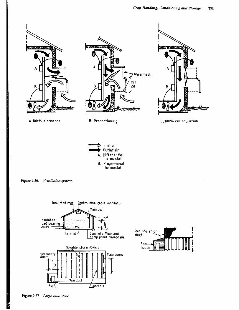
Crop Handling. Conditioning and Storage 251
A.lOO% airchange B. Proportioning
1 Inlet air e Outlet air
A. Differential thermostat
B. Proportiona 1 thermostat
Figure 9.36. Ventilation sq’stem.
lnsulakd roKf, pntroilable gable ventilator
lnsu la load b walls
np proof membrane
Movable store division
mesh
C.lOO% recirculation
FaA /Laterals
Figure 9.37 Large bu!k store.
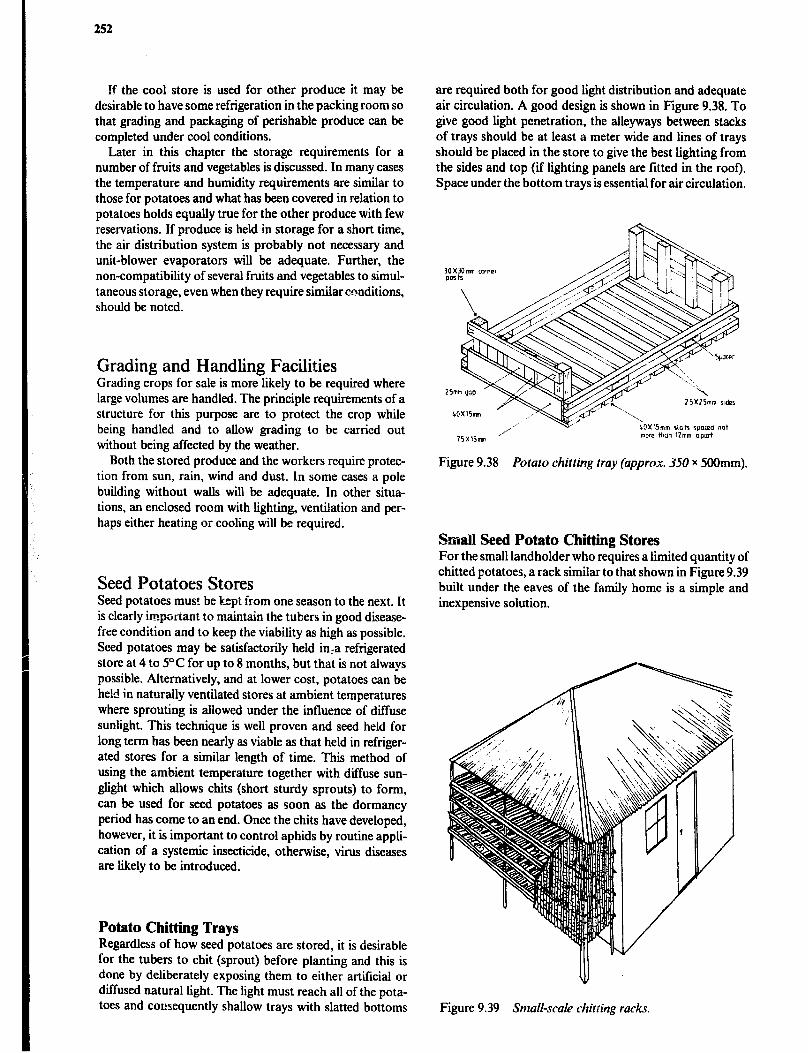
252
If the cool store is used for other produce it may be desirable to have some refrigeration in the packing room so that grading and packaging of perishable produce can be completed under cool conditions.
Later in this chapter the storage requirements for a number of fruits and vegetables is discussed. In many cases the temperature and humidity requirements are similar to those for potatoes and what has been covered in relation to potatoes holds equally true for the other produce with few reservations. If produce is held in storage for a short time, the air distribution system is probably not necessary and unit-blower evaporators will be adequate. Further, the non-compatibility of several fruits and vegetables to simul- taneous storage, even when they require similar conditions, should bc noted.
Grading and Handling Facilities Grading crops for sale is more likely to be required where large volumes are handled. The principle requirements of a structure for thii purpose are to protect the crop while being handled and to allow grading to be carried out without being affected by the weather.
Both the stored produce and the workers require protec- tion from sun, rain, wind and dust. In some cases a pole building without walls will be adequate. In other situa- tions, an enclosed room with lighting, ventilation and per- haps either heating or cooling will be required.
Seed Potatoes Stores Seed potatoes must bc kept from one season to the next. It is clearly imporiant to maintain the tubers in good disease- free condition and to keep the viability as high as possible. Seed potatoes may be satisfactorily held in,a refrigerated store at 4 to 5°C for up to 8 months, but that is not always possible. Alternatively, and at lower cost, potatoes can be he!d in naturally ventilated stores at ambient temperatures where sprouting is allowed under the influence of diffuse sunlight. This technique is well proven and seed held for long term has been nearly as viable as that held in refriger- ated stores for a similar length of time. This method of using the ambient temperature together with diffuse sun- glight which allows chits (short sturdy sprouts) to form, can be used for seed potatoes as soon as the dormancy period has come to an end. Once the chits have developed, however, it is important to control aphids by routine appli- cation of a systemic insecticide, otherwise, virus diseases are likely to be introduced.
Potato Chitting Trays Regardless of how seed potatoes are stored, it is desirable for the tubers to chit (sprout) before planting and this is done by deliberately exposing them to either artificial or diffused natural light. The light must reach all of the pota- toes and consequently shallow trays with slatted bottoms
are required both for good light distribution and adequate air circulation. A good design is shown in Figure 9.38. To give good light penetration, the alleyways between stacks of trays should be at least a meter wide and lines of trays should be placed in the store to give the best lighting from the sides and top (if lighting panels are fitted in the roar). Space under the bottom trays is essential for air circulation.
ZSXlSmm rxkr
/’ --a-’ ~OXlSmm rloh ~p(~ceci not
15X15mn more than llmm ap01I
Figure 9.38 Potato chitting tray (approx. 350 x 5OOmm).
Small Seed Potato Chitting Stores For the small landholder who requires a limited quantity of chitted potatoes, a rack similar to that shown in Figure 9.39 built under the eaves of the family home is a simple and inexpensive solution.
Figure 9.39 Small-scale chitting racks.
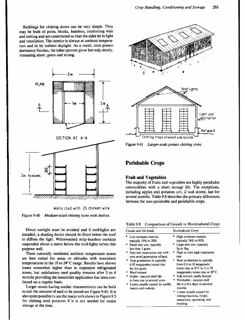
Crop Handling, Conditioning and Storage 253
Buildings for chitting stores can be very simple. They may be built of poles, blocks, bamboo, reinforcing wire and netting and are constructed so that the sides let in light and ventilation. The interior is always at ambient tempera- ture and lit by indirect daylight. As a result, once potato dormancy finishes, the tuber sprouts grow but only slowly. remaining short, green and strong.
PLAN
SECTION AT A-A
2mA
f
Walls ciad with 25 chicken wire
Figure 9.40 Medium-sized chitting st$re with shelves.
Direct sunlight must be avoided and if roof-lights are installed, a shading device should be fitted below the roof to diffuse the light. Whitewashed strip-bamboo curtains suspended about a metre below the roof-tights serves this purpose well.
These naturally ventilated ambient temperature stores are best suited for areas or altitudes with maximum temperatures in the 18 to 24” C range. Results have shown losses somewhat higher than in expensive refrigerated stores, but satisfactory seed quality remains after 5 to 6 months providing the insecticide application has been con- tinued on a regular basis.
Larger stores having similar characteristics can be built to suit the amount of seed to be stored see Figure 9.41. It is also quite possible to use the maize crib shown in Figure 9.5 for chitting seed potatoes if it is not needed for maize storage at the time.
-J(
Light and ,venrilation I-- Rat guard
Figure 9.4 1 Larger-scale potato chbting store.
Perishable Crops
Fruit and Vegetables The majority of fruits and vtgetables are highly perishable commodities with a short storage life. The exceptions, including apples and potatoes can, if well stored, last for several months. Table 9.8 describes the primary differences between the non-perishable and perishable crops.
Table 9.8 Comparison of Cereals vs Horticultural Crops
Cereals and Oil Seeds Horticultural Crops
+ Low moisture content. * High moisture content,
typically 10% to 20% typically 70% to 95%
* Small unit size, typically * Large unit size, typically
less than I gram 5g to 5kg
* Very low respiration rate with * High to very high respiration
very small generation of heat. rate.
* Heat production is typically * Heat production is typically
0.05 megajoules/tonne/day from 0.5 to 10 megajoule/
for dry gram. tonne/day at O’C to 5 to 70
* Hard texture megajoules/ tonne/day at 20°C.
* Stable - natural shelf life * Soft texture, easily bruised
is from one to several years * Perishable - natural shelf
* Losses usually caused by molds, life is a few days to serveral
insects and rodents. months
* Losses usually caused by
’ rotting (bacteria. fungi).
senescence. sprouting. and
bruising.
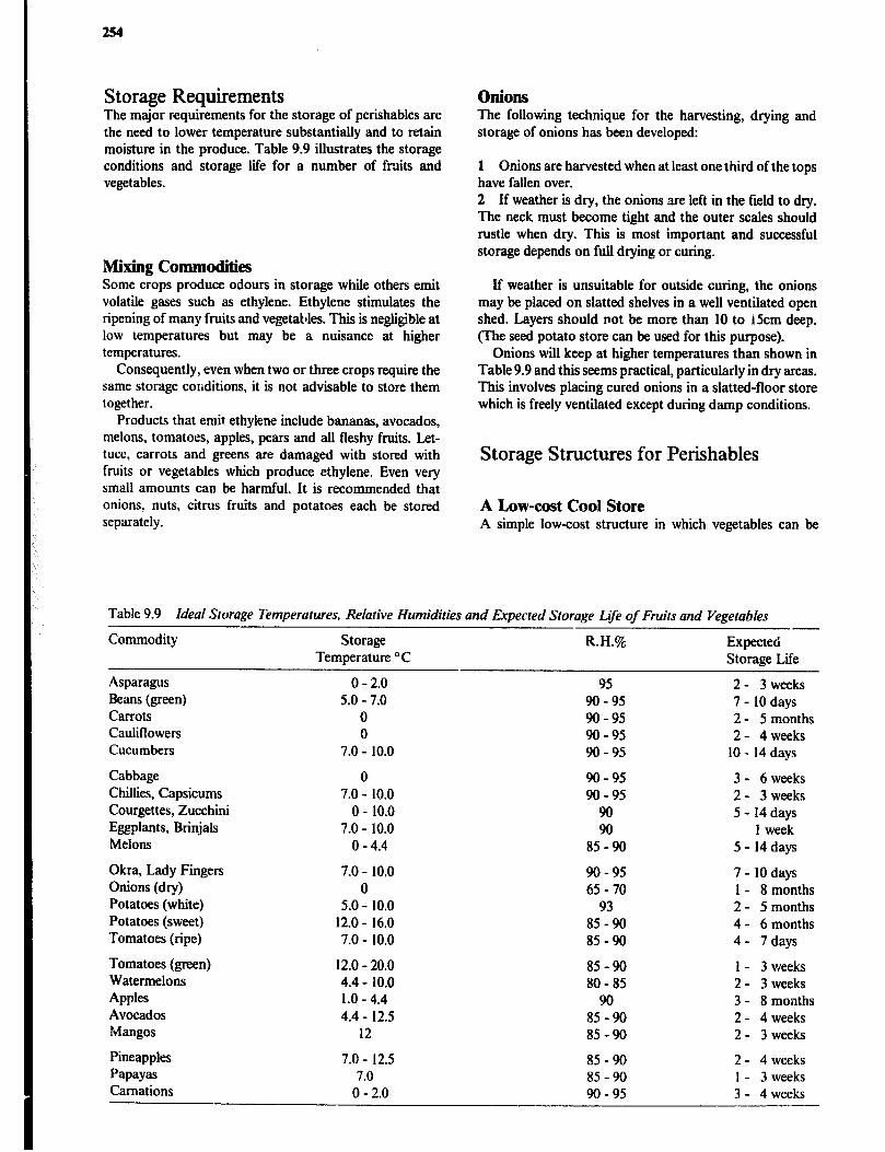
254
Storage Requirements Onions The major requirements for the storage of perishables are the need to lower temperature substantially and to retain moisture in the produce. Table 9.9 illustrates the storage conditions and storage life for a number of fruits and vegetables.
The following technique for the harvesting, drying and storage of onions has been developed:
1 Onions are harvested when at least one third of the tops have fallen over. 2 If weather is dry, the onions are left in the field to dry. The neck must become tight and the outer scales should rustle when dry. This is most important and successful storage depends on full drying or curing.
Mixing Commodities Some crops produce odours in storage while others emit volatile gases such as ethylene. Ethylene stimulates the ripening of many fruits and vegetables. This is negligible at low temperatures but may be a nuisance at higher temperatures.
Consequently, even when two or three crops require the same storage conditions, it is not advisable to store them together.
Products that emit ethylene include bananas, avocados, melons, tomatoes, apples, pears and all fleshy fruits. Let- tuce, carrots and greens are damaged with stored with fruits or vegetables which produce ethylene. Even very small amounts can be harmful. It is recommended that onions, nuts, citrus fruits and potatoes each be stored separately.
If weather is unsuitable for outside curing, the onions may be placed on slatted shelves in a well ventilated open shed. Layers should not be more than 10 to 15cm deep. (The seed potato store can be used for this purpose).
Onions will keep at higher temperatures than shown in Table 9.9 and this seems practical, particularly in dry areas. This involves placing cured onions in a slatted-floor store which is freely ventilated except during damp conditions.
Storage Structures for Perishables
A Low-cost Cool Store A simple low-cost structure in which vegetables can be
Table 9.9 Ideal Storage Temperatures, Relative Humidities and Expected Storage L&e of Fruits and Vegetables
Commodity
Asparagus Beans (green) Carrots Cauliflowers Cucumbers
Cabbage Chillies, Capsicums Courgettes, Zucchini Eggplants, Brinjals Melons
Okra, Lady Fingers Onions (dry) Potatoes (white) Potatoes (sweet) Tomatoes (ripe)
Tomatoes (green) Watermelons Apples Avocados Mangos
Pineapples Papayas Carnations
Storage Temperature o C
0 - 2.0 5.0 - 7.0
0 0
7.0 - 10.0
0 7.0 - 10.0
0 - 10.0 7.0 - 10.0
0 - 4.4
7.0 - 10.0 0
5.0 - 10.0 12.0 - 16.0 7.0 - 10.0
12.0 - 20.0 4.4 - 10.0 1.0 - 4.4 4.4 - 12.5
12
7.0 - 12.5 7.0
0 - 2.0
R.H.%
95 90 - 95 90 - 95 90-95 90 - 95
90 - 95 90 - 95
90 90
85 90 -
90 - 95 65 70 -
93 85 - 90 85 -90
85 -90 80 85 -
90 85 -90 85-90
85 -90 85 - 90 90 95 -
Expected Storage Life
2- 3weeks 7 - 10 days 2 - 5 months 2- 4 weeks
10 - 14 days
3- 6weeks 2 - 3 weeks 5 - 14 days
1 week 5 - 14 days
7 - 10 days 1 - 8 months 2 - 5 months 4- 6 months 4 - 7 days
1 - 3 weeks 2 - 3 weeks 3 - 8 months 2 - 4 weeks 2- 3weeks
2 - 4 weeks 1 - 3 weeks 3 - 4 weeks

Crop Handling, Conditioning and Storage 255
stored for the few hours between harvesting and transport- ing to market should be useful to growers of all sizes. The basic construction is similar to that shown in Figure 9.32. A simple frame is constructed with poles or other low cost materials. Covered with grass or other thatching mateiial, protection is provided for the produce from excess temper- ature and moisture loss until it can be transported to market.
The wall should be extended to .qound level on three sides but left open on the fourth (prevailing wind) side for ventilation. This allows for free air movement most of the time, but canvas flaps should be provided for closing the ventilation openings if desirable.
The grass roof and walls can be kept wet with a sprinkler pipe-line, or if that is not available, the thatching can be hand sprinkled as required. The interior will be kept cool and moist with temperatures as much as 5 to 8OC lower than outside. More important, produce harvested late in
the afternoon can be cooled during the night with resulting temperatures the following noon as rrluch as 10°C below ambient.
Commercial Cool Store As shown in Table 9.9, only a few crops, including pota- toes, onions, carrots and apples can be stored for periods longer than a few days or weeks. However, the wholesale merchant will require short term refrigerated storage for his produce and as indicated, separate rooms will be needed for crops that are not compatible with each other in storage. As with refrigerated potato stores, attention must be given to adequate insulation, good vapour sealing and large size evaporators which help to maintain high humidity.
Futher Reading Araullo E.V.. de Padua P.B., Graham M., Rice Postharvest Technology, Ottawa, International Development Research
Centre, 1976. Birewar B.R., Varma B.K., Ramam C.P., Kanjilal S.C., Traditional Storage Structures in India and their Improvements,
Hapur, lndian Grain Storage Institute. Bond E.J., Manualof Fumigatioinfor Insect Control, FAO Plant Production and Protection Paper no. 54, Rome, Food and
Agriculture Organization of the United Nations, 1984. Booth R.H., Shaw R.L., Principles of Potato Storage, Lima , International Potato Centre, 1981. Community Development Trust Fund of Tanzania, Appropriate Technology for Grain Storage, Report of a Pilot Project,
New Haven, Economic Development Bureau, Inc., 1977. Dichter D., Manual on Improvement Farm & Village Level Grain Storage Methods, Eschborn, German Agency for
Technical Cooperation, Ltd. (GTZ) 1978. Esmay M., Soemangat, Eriyatno, Phillips A., Rice Postproduction Technology in the Tropics, Honolulu, East-West Centre,
The University Press of Hawaii, 1979. Farm Electric Centre, Grain Drying and Storage, Warwickshire, National Agriculture Centre. Farm Electric Centre, Vegetable Storage, A Guide to the Practical Design of Installations, Warwickshire, National
Agriculture Centre, 1974. Food and Agriculture Organization of the United Nations, the FAO Agricultural Services Bulletins, No.: 5. Sundrying Fruits and Vegetables, 1970 6. Cashew Nut Processing, 1970 8. Cassava Processing, 2nd ed., 1977. 13. Fruit Juice Processing, 1972 17. Airtight Grain Storage, 1973 19. Co/d Storage- Design and Operation, 1973 22. Rice Milling Equipment-Operation and Maintenance, 1974 23. Rice drying, 1974 26. Tea Processing, 1974 36. China: Rural Processing Technology, 1979 39. Small-Scale Cane Sugar Processing and Residue Utilization, 1980 40. On-farm Maize Drying and Storage in the Humid Tropics, 1980 43. Food Loss Prevention in Perishable Crops, 1980 49. China: Grain Storage Structures, 1982. SO. China: Post-harvest Grain Technology, 1982. 52. Aeration of Grain in Subtropical Climates, 1982. 53. Processing and Storage of Foodgrains by Rural Families, 1983. Food and Agriculture Organization of the United Nations, Post-harvest Losses in Quality of Food Grains, FAO Food and
Nutrition Paper 29, Rome, Food and Agriculture Organization of the United 1 “ations, 1983. Food and Agriculture Organization of the United Nations, Rodent Control in Agriculture, FAO Plant Production and
Protection Paper no. 40, Rome, Food and Agriculture Organization of the United Nations, 1982.

256
Food and Agriculture Organization of the United Nations, Technical Guideline for Maize Seed Technology. Rome, Food and Agriculture Organization of the United Nations, 1982.
Golob P., Mixing Insecticide Powders with Grain for Storage, Rural Technology Guide no. 3, London, Tropical Products Institute, 1977.
Golob P., Webley D.J., The Use of Plant and Minerals as Traditional Protectants of Stored Products, London, Tropical Products Institute, 1980.
Graf Ballestrem C., Holler H.J., Potato Production in Kenya, Experiences and Recommendations for improvements, Eschborn, German Agency for Technical Cooperation, Ltd., (GTZ), 1977.
Hall C.W., Drying and Storage of Agricultural Crops, Westport, AVI Publishing Company, Inc., 1980. Hall D.W., Handling and Storage of Food Grains in Tropical and Subtropical Areas, Rome, Food and Agriculture
Organization of the United Nations, 1970. Harris K.L., Lindblad C.J., Postharvest Grain Loss Assessment Methods for the Evaluation of Post Harvest Losses,
American Association of Cereal Chemists, 1978. International Ferroeement Information Centre, Ferrocemenf Grain Storage Bins, Do It Yourself Series, no. 1, Bangkok,
International Ferrocement Information Centre, 1979. Lindblad C., Druben L., Small Farm Grain Storage, Appropriate Technologies for Development, Mt. Rainer,
Action j Peace Corps and Volunteers in Technical Assistance, 1976. McLean K.A., Handling and Storage of Combinable Crops, Ipswich, Farming Press Ltd., 1980. Nilson C., Pchistorp S., Henriksson R., Ferrocement Storesfor Ragged Grain andother’Purposes, Reports 24 and 36, Lund,
Swedish University of Agricultural Sciences, Department of Farm Buildings, 1982 and 1984. Nygaard-Pedersen G., Solid- Walled Grain Bins, Lusaka, Ministry of Agriculture and Water Development, 1982. Plucknett D.L. (ed), Small-Scale Processing and Storage of Tropical Root Crops, Westview Tropical Agricultural Series,
No. 1, Boulder, Colorado, Westview Press Inc., 1979. Rural Structures Unit, The Improved Maize Crib, A Guide to Small Farm Grain S:orage, Volume I: Theoretical
background, Volume II: Description and Drawings, Nakuru, Ministry of Agriculture, 1984. Siegel A., Fawcett B., Food Legume Processing and Utilization, with Special Emphasis on .rlpplication in Developing
Counrries, Ottawa, International Development Research Centre, 1976. Tropical Development and Research Institute, Tropical Stored Products Information, The Journal of the Storage
Department of the Tropical Development and Research Institute (formerly Tropical Products Institute). Willis R.H.H., Lee T.H., Graham D., McGlasson W.B., Hall E.G., Postharvest; An Introduction to the Physiology and
Handling of Fruit and Vegetables, London, Granada Publishing Ltd., 1981. World Food Programme, Food Storage, Handbook on Good Storage Practice, Rome, World Food Programme, 1979.
Chapter 10
Animal Housing
The main purpose for man to keep livestock is to convert energy in feed into products which can be utilised by human beings, such as milk, eggs, meat, wool, hair, hides and skins, draught power and manure (fertilizer). Tradi- tional, extensive livestock production involving indigenous breeds and low cost feeding will usually have low perfor- mance and can therefore only justify minimal, if any, expenditure for housing. However, where improved breeds, management and feeding is available it will usually be economically beneficial to increase the production intensity and to construct buildings and other livestock structures to provide for some environmental control, reduced waste of purchased feed stuffs and better control of diseases and parasites, but this rule is not invariable. It is,
for example, difficult to identify an economic benefit in sheep production arising from any but the use of the least expensive buildings. At the other end, a relatively expen- sive farrowing house, providing a high level of environ- mental control, may improve the survival rate in piglets sufficiently to both justify the cost and add to the profita- bility of the production unit.
The planning and design of any structure for a livestock production system involves many alternatives for each of numerous variables and car. therefore be turned into a complex and theoretical subject, but is usually far simpler in reality. However, every facet of the design, be it the production system, equipment, building materials, layout or location, will play a part in determining the profitability of the production and any variation in one of them may significantly affect the profitability on the whole. One spe- cial difficulty when designing livestock structures for tropi- cal climates is that most research and development has, up to now, been concerned with the conditions in temperate or cold climates. Any recommendations derived from such experiments and applied uncritically in warm climates may result in an adverse environment for the animals and in very high building aud operation costs.
Animal Behaviour
Introduction Understanding of domestic animal behaviour and man’s relationship with farm animals may greatly contribute to increased economic benefit in animal husbandry and easier handling of the animals. The importance of animal behav- iour aspects in the design of animal housing facilities generally increase with the intensity of production and the degree of confinement. Many modern farming systems greatly reduce the freedom for animals to choose an envir- onment in which they feel comfortable. Instead they are forced to resort to an environment created by man.
Animals that as far as possible can exercise their natural, species-specific movements and behaviour patterns are
less likely to be stressed or injured and will therefore pro- duce better. In practical design of an animal production system and any buildings involved, many other factors such as feeding, management, thermal environment, con- struction and economics can be equally or more important, however.
The animals can to some extent adapt their behaviour to suit a bad design and on a long term basis they can be changed by breeding and selection, hilt generally it will be much easier to fit the husbandry and building design to the animals. The life span of a building is usually 5 to 15 years and that makes it clear that even a small increase in produc- tion or decrease in frequency of injury and disease, in waste of feed or in labour requirements for handling of the animals will repay all the thought and care that has been put into the design, lay-out and construction of the build- ing. Furthermore it may cost as much to construct a build- ing that is poorly designed and equipped for the animals as one that works well.
Behaviour Patterns Farm animals are born with certain fixed behaviour patt- ems such as pecking in chickens and nursing in mammals, but most behaviour patterns develop Lhrough play and social contact with other animals of their kind and under the influence of environmental stimulation and genetic factors. Behaviour variation within a species is mainly caused by differences in the environment and between the sexes but breed, strain and individual variance also have an influence. Domestic animals show great ability to modify their behaviour patterns in relation to environments and to learn by experience.
Animals often form a daily cycle of habits caused by the uniformity of husbandry, for example, the regular varia- tion in light during night and day relate to internal physio- logical rhythms. This is why cows gather around the barn just before milking time. Some behaviour patterns change from season to season, partly as a response to the changing weather. Cows tend to be more active during the night in the hot season and spend less time lying down if outside in the wet season. Many domestic animals show a slight seasonal breeding pattern.
Domestic animals under conditions of close captivity, frequently show abnormal behaviour such as stereotyped movements or inappropriate sexual behaviour, particu- larly if they are unable to escape from or adapt to the situation. However, many disturbed behaviours have more complex causes. For example, tail and ear biting in pigs may be associated with boredom, breakdown of social order, too high stocking rate, too low fibre content in the feed, malnutrition, poor ventilation leading to high humid- ity and temperature, no bedding, inadequate trough space and watering points, skin disease, parasites, teething prob- lems etc.
258
Social Rank Order Domestic animals are highly sociable and naturally form groups. Males and females form separate groups, except during the breeding season, and the young tend to form small groups in the proximity of the female group.
When strange adult animals meet for the first time they are likely to fight to establish dominance-subordinance relationships. The resulting pecking order or social rank order in which one or two animals are invariably dominant is usually formed quickly. Physical age and weight are the main factors determining social rank, but sex, height and breed can also be of influence. The group can live in relative harmony as long as each animal knows its place and gives way to animals of higher rank. However, the order is seldom strictly hierarchic or static. Some animals of low rank may dominate others whose positions are normally higher and fast growing and maturing animals may move up the ladder.
Introduction of new animals in a group or mixing of groups will normally lead to fighting until a new social order is formed and this may cause a growth check as well as injury.
The normal response to aggressive behaviour in a group with established social order is for the subordinate animal to move away. The building layout must allow space for this and narrow passages and comers where one animal cai:: be trapped by another should be avoided in pens and yards. The order is usually stable provided the group is small so that all animals in it can remember each others position, i.e. fewer than 60 to 80 cows, 12 to 15 pigs or about 100 chickens.
Animal Behaviour Studies Experiments with the objective of improved design of animal housing, its furnishing and equipment, usually employ either of the following methods:
a A choice of environment is provided for the animals and their preference for the different facilities is recorded. b The behaviour of animals in an experimental environ- ment is studied and the result is compared to the behaviour of animals in a reference system, on a free range, or that of their wild relatives. Often the study is confined to activities like resting, eating, standing/ walking, but sometimes the frequency of other behaviour patterns, such as investiga- tive, agnostic, sexual, care-giving, care-soliciting, elimina- tive, etc. is included.
In addition productivity and frequency of injury and disease is recorded.
Animal Behaviour and Building Design Below are some examples of how animal behaviour can influence the design of structures. More exampies will be given when housing facilities for the various species are described later in this chapter.
Cattle normally live in herds, but when giving birth, the cow attempts to find a quiet, sheltered place away from the disturbance of other cows and humans. The cow needs to be alone with her calf for some time after bii for the cow-calf bond to be established. A cow, confined in a loose housing system, who is approaching calving, should there- fore be removed from the herd and put in an individual pen.
Hens spend considerable time in the selection of a nest, which is on the ground. Nesting is character&d by secrecy and careful concealment. Hens in deep litter systems there- fore, sometimes lay eggs on the floor instead of in the nestboxes, especially if the litter is quite deep or there arc dark comers in the pen.
To avoid this, plenty of fresh litter is provided in the nests, and they are kept in semidarkness and designed with a rail in front so that birds can inspect the nests prior to entry. An additional measure is to start with the nestboxes on the floor and slowly raise them to the desired level over a period of days.
Sows are nest builders and should be transferred to clean farrowing pens one to two weeks before giving birth, and given some bedding so that they can build a nest. Gestrus, especially in gilts, is increased by the smell, sight and physical presence of a boar. Gilts and sows awaiting mating should therefore be kept in pens adjoining the boar pen.
Cattle prefer to be able to see while drinking, therefore more animals can drink at once from a long, narrow trough than from a low round one. With cattle (and hens) feeding is typically a group activity, therefore space at the feed trough must be provided for all the animals at one time. At pasture, undersized feed or water troughs can result in inadequate feeding and watering of the animals which are lowest in rank, because these animals will likely be excluded from the trough, but they will still tend to leave with the rest of the herd after feeding or watering.
To prevent waste of feed a trough should be designed to suit the particular behaviour pattern each species exhibits while feeding i.e. pecking in hens, rooting with a forward and upward thrust in pigs, wrapping their tongue around the feed (grass) and jerking their head forward in cattle.
Artificially reared calves bunt the bucket instead of the cows udder, and this requires a sturdy holder for the bucket. The habit of suckling each other is a problem in dairy calves. The problem can be reduced by making the calves suckle harder and longer for their feed by using a rubber teat rather than a bucket and by giving them access to dry feed. Assuming intersuckling is not a problem, a group pen for calves is more natural than individual pens and helps ensure normal activity and resting.
Sheep are vigilant and tight flocking, and respond to disturbance by fleeing. When designing handling facilities these characteristics should be taken into account. A race should be straight, level, fairly wide, without blind ends, and preferably have close-boarded sides. Sheep which are following should be able to see moving sheep ahead, but advancing sheep should not see the sheep behind as they will tend to stop and turn around. Sheep move best from dark into light areas and dislikereflections abrupt changes in light contrast and light shining through slats, grates or

Animal Housing 259
holes. Handling facilities should be examined from the height of the sheep’s eye level rather than the human to detect flaws in the design.
Animal Environmental Requirements The capacity of an animal to produce differs between species, breeds and strains as a result of genetic factors. However, a complex of inter-related factors in the animal husbandry will influence the animal’s ability to utilize that capacity for growth, development and production.
Progress in breeding and feeding for further increase in production and efficiency can be liited by environmental factors. Research into these factors has therefore been increasing in recent yearqespecially in countries having intensive animal production.
Animal housing design is mainly concerned with the physical environment, in particular climatic and mechani- cal factors, but all other factors should also be considered in order to create a good layout, where healthy, high yielding animals can be provided with correct feeding, can be easily handled and can produce without stress or suffer- ing physical harm.
Heat Regulation All domestic livestock are homeotherms; that is, they maintain relatively constant internal body temperatures, usually within a 1 to 2°C range. Normal body temperatures of some domestic animals and humans are given in Table 10.1.
Table 10.1 Normal Body Temperatures af Domestic Animals and Humam
Animals Temperature o C
Average Range
Dairy Cow Beef Cow Pig Sheep Goat Horse Chicken Human
38.6 38.0 - 39.3 38.3 36.7 - 39.1 39.2 38.7 - 39.8 39.1 38.3 - 39.9
38.7 - 40.7 37.9 37.2 - 38.2 41.7 40.6 - 43.0 37.0
The body temperature of most domestic animals is con- siderably higher than the environmental temperature to which they are exposed most of the time. They maintain their body temperatures by balancing internal heat produc- tion and heat loss to the environment. The hypothalinus gland acts as a body thermostat by stimulating mecha- nisms to counteract either high or low ambient tempera- tures. For example, increased conversion of feed-to-heat energy is used to counteract low ambient temperatures, while for example increased respiration (rate and volume) and blood circulation in the skin counteracts high ambient temperatures. Varying temperature also results in changed behaviour. Most animals reduce their level of activity in a hot environment and, for example, pigs lie clustered in a heap at low temperatures, while they lie spread out with extended limbs at high temperatures. This would suggest
Figure 10.1 Classification of factors influencing livestock production.

260
increased space requirement for pigs held in a warm, tropi- cal climate, The body can tolerate short periods of heat stress, but if the ambient temperature exceeds the body temperature for an extended period, it may prove fatal.
When feed is converted by the animal’s metabolism for the production of milk, eggs, meat, off-spring etc., heat is produced as a by-product. An increased production level and thus feed requirement will therefore result in increased internal heat production. High yielding animals are conse- quently more likely to suffer from heat stress in a hot climate than are low yielding ones.
Feeding libre-rich, low digestible feed stuffs like hay will result in high heat-production because of increased muscu- lar activity in the alimentary tract and, in ruminants, incttased micro-organism activity in the rumen. An increased share of concentrates in the feed may therefore reduce heat stress in an animal under hot climatic conditions.
Animal Moisture and Heat Production Heat is produced centrally in the deep body. The surplus is conducted to the skin surface where it is given off to the atmosphere as sensible heat by means of convection, con- duction and radiation and as latent heat by means of evaporation of moisture from the lungs and skin. lncreas- ing ambient temperature, resulting in less temperature dif- ference between the body surface and the air, will decrease the amount of heat that can be emitted as sensible heat. Instead a larger proportion is given off as latent heat, that is. heat employed to vapourize moisture.
Table 10.2 lists values for animal heat and moisture production at various temperatures. The heat and moisture produced by the animals confined in a structure must be removed by ventilation. in the tropics, sufficient ventila- tion flow is usually provided for by the use of open-sided structures.
However, if an enclosed building is used, a range of ventilation flow rates must be provided for in the building design. The minimum ventilation rate should remove the moisture produced, but retain as much sensible heat as possible during cold periods. The maximum ventilation rate should remove enough of the sensible heat produced so that a small temperature difference, usually 2 to 4OC, can be maintained between inside and outside. It should be noted that ventilation alone can only maintain the building temperature at slightly above ambient. Ventilation is dis- cussed in more detail in Chapter 7.
Climatic Factors
Temperature The over-riding environmental factor affecting the physio- logical functions of domestic animals is temperature. For most farm animals a mean daily temperature in the range 10 to 20°C is referred to as the “comfort zone”. In this
range the animal’s heat exchange can be regulated solely by physical means such as constriction and dilation of blood vessels in the skin, ruffling up the fur or feathers and regulation of the evaporation from lungs and skin. At the upper and lower critical temperatures the physical regula- tion will not be sufficient to maintain a constant body temperature and the animal must, in addition, decrease or increase its metabolic heat production.
A further decrease or increase in temperature will even- tually bring the temperature to a point beyond which not even a change in heat production will be sufficient to maintain homeothermy.
A very young animal, lacking fully developed temperature-regulating mechanisms, particularly the abil- ity to increase heat production by increased metabolism, is much more sensitive to its thermal environment and requires higher temperatures.
Humidity Poultry do not have sweat glands, so all evaporative heat loss must originate from the respiratory tract. Other lives- tock species have varying abilities to sweat and in descend- ing order they are as follows: Horse, donkey, cattle, buf- falo, goat, sheep and pig.
In a hot-dry climate evaporation is rapid, but in a hot- humid climate the ability of the air to absorb additional moisture is limited and the inadequate cooling may result in heatstress.
. Too low humidity in the air will cause irritation of the mucous membranes, while too high humidity may pro- mote growth of fungus infections. High humidity may also contribute to decay in structures. If possible keep the rela- tive humidity in the range of 40 to 80%.
Radiation The heat load on a grazing animal can be considerably increased by direct solar radiation and radiation reflected from clouds or the ground. A white hair coat will absorb less radiant energy than a dark, but the heat penetrates deeper in a white, loose coat. Air movements will dispel the heat and reduce the differences. Furthermore, solar radia- tion may adversely affect the animal’s skin in particular breeds having unpigmented skin.
Heat gain by radiation can be effectively reduced by the provision of a shaded area. It must, however, be suffi- ciently large to allow space between the animals so that the heat loss by other means is not reduced. Grass covered ground in the surroundings of the shade will reflect less radiation than bare soil.
Air Movements Air movements will assist in heatloss by evaporation and by conduction/convection as long as the air temperature is lower than the skin temperature. When the air temperature
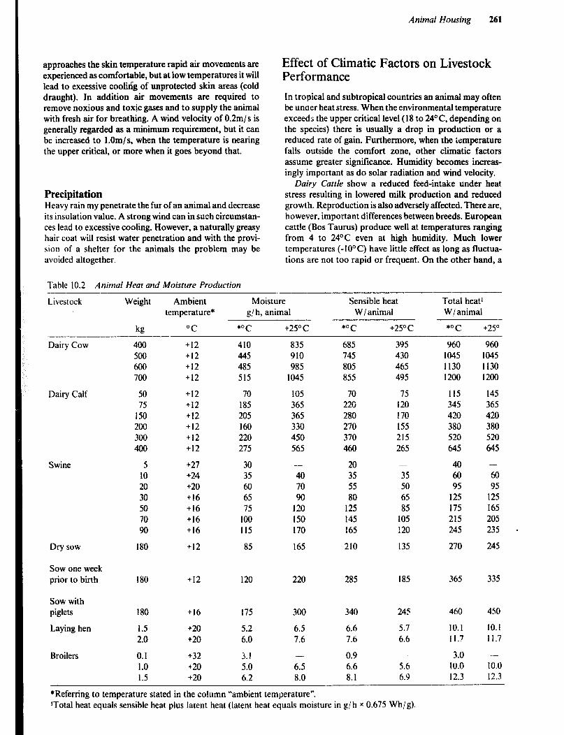
Animal Housing 261
approaches the skin temperature rapid air movements are experienced as comfortable, but at low temperatures it will lead to excessive cooling of unprotected skin areas (cold draught). In addition air movements are required to remove noxious and toxic gases and to supply the animal with fresh air for breathing. A wind velocity of 0.2m/s is generally regarded as a minimum requirement, but it can be increased to l.Om/s, when the temperature is nearing the upper critical, or more when it goes beyond that.
Precipitation Heavy rain my penetrate the fur of an animal and decrease its insulation value. A strong wind can in such circumstan- ces lead to excessive cooling. However, a naturally greasy hair coat will resist water penetration and with the provi- sion of a shelter for the animals the problem may be avoided altogether.
Effect of Climatic Factors on Livestock Performance
In tropical and subtropical countries an animal may often be unaer heat stress. When the environmental temperature exceeds the upper critical level (18 to 24OC, depending on the species) there is usually a drop in production or a reduced rate of gain. Furthermore, when the temperature falls outside the comfort zone, other climatic factors assume greater significance. Humidity becomes increas- ingly important as do solar radiation and wind velocity.
Dairy Cattle show a reduced feed-intake under heat stress resulting in lowered milk production and reduced growth. Reproduction is also adversely affected. There are, however, important differences between breeds. European cattle (Bos Taurus) produce well at temperatures ranging from 4 to 24’C even at high humidity. Much lower temperatures (-1O’C) have little effect as long as fluctua- tions are not too rapid or frequent. On the other hand, a
Table 10.2 Animal Heat and Moisture Production
Livestock Weight Ambient Moisture Sensible heat Total heat’ temperature* g/h, animal W / animal W/animal
kg “C *OC +25O c *OC +25oc *OC +25O
Dairy Cow
Dairy Calf
Swine
Dry sow
Sow one week prior to birth
Sow with piglets
Laying hen
Broilers
400 +I2 410 500 +I2 445 400 +I2 485 700 +12 515
50 +I2 70 75 +I2 185
150 +I2 205 200 +I2 160 300 +I2 220 400 +12 275
5 +27 30 10 +24 35 20 +20 60 30 +16 65 50 +I6 75 70 +I6 loo 90 +I6 115
180 +12 85
835 910 985
1045
105 365 365 330 450 565
395 430 465 495
75 120 170 155 215 265
-
40 70 90
120 150 170
165
685 745 805 855
70 220 280 270 370 460
20 35 55 80
125 145 165
210
-
35 SO 65 85
105 120
135
Y60 1045 1130 1200
115 345 420 380 520 645
40 60 95
125 175 215 245
270
960 1045 1130 1200
145 365 420 380 520 645
-
60 95
125 165 205 235 -
245
180 +I2 120 220 285 185 365 335
180 +I6 175
1.5 2.0
0.1 1.0 1.5
+20 5.2 +20 6.0
300
6.5 7.6
340
6.6 7.6
0.9 6.6 8.1
245
5.7 6.6
460
10.1 Il.7
3.0 10.0 12.3
450
10.1 11.7
+32 j.! -
+20 5.0 6.5 +20 6.2 8.0
-
5.6 6.9
-
10.0 12.3
*Referring to temperature stated in the column “ambient temperature”. ‘Total heat equals sensible heat plus latent heat (latent heat equals moisture in g/h x 0.675 Wh/g).
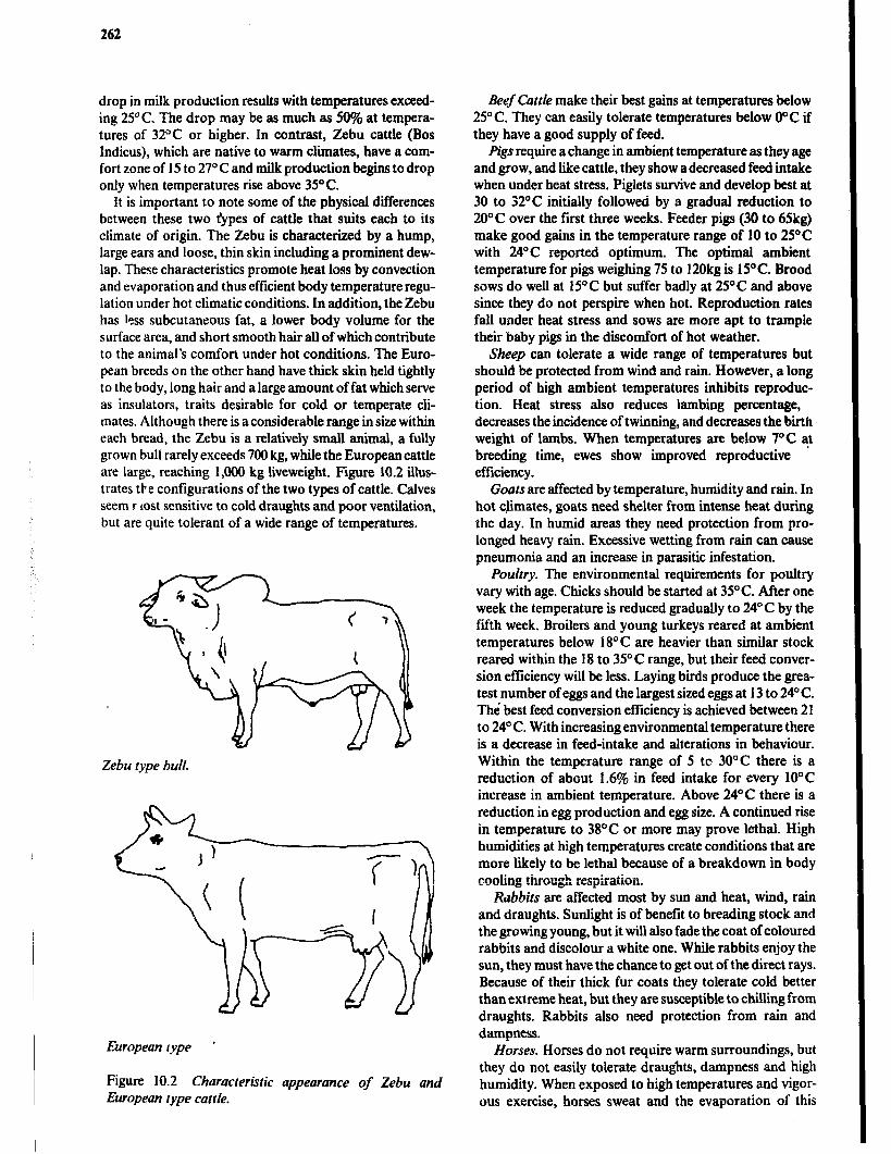
262
drop in milk production results with temperatures exceed- ing 25% The drop may be as much as 50% at tempera- tures of 32°C or higher. In contrast, Zebu cattle (80s Indicus), which are native to warm climates, have a com- fort zone of I5 to 27O C and milk production begins to drop only when temperatures rise above 35’C.
It is important to note some of the physical differences between these two types of cattle that suits each to its climate of origin. The Zebu is characterized by a hump, large ears and loose, thin skin including a prominent dew- lap. These characteristics promote heat loss by convection and evaporation and thus efficient body temperature regu- lation under hot climatic conditions. In addition, the Zebu has less subcutaneous fat, a lower body volume for the surface area, and short smooth hair all of which contribute to the animal’s comfort under hot conditions, The Euro- pean breeds on the other hand have thick skin held tightly to the body, long hair and a large amount of fat which serve as insulators, traits desirable for cold or temperate cli- mates. Although there is a considerable range in size within each bread, the Zebu is a relativeiy small animal, a fully grown bull rarely exceeds 700 kg, while the European cattle are large, reaching 1,000 kg liveweight. Figure 10.2 iUus- trates the configurations of the two types of cattle. Calves seem r lost sensitive to cold draughts and poor ventilation, but are quite tolerant of a wide range of temperatures.
Zebu type bull.
European type ’
Figure 10.2 Characteristic appearance of Zebu and European type cattle.
Beef Cattle make their best gains at temperatures below 25°C. They can easily tolerate temperatures below O°C if they have a good supply of feed.
pigs require a change in ambient temperature as they age and grow, and like cattle, they show adecreased feed intake when under heat stress. Piglets survive and develop best at 30 to 32OC initiahy followed by a gradual reduction to 20°C over the first three weeks. Feeder pigs (30 to 65kg) make good gains in the temperature range of 10 to 2YC with 24OC reported optimum. The optimal ambient temperature for pigs weighing 75 to 120kg is 15OC. Brood sows do well at 15’C but suffer badly at 25OC and above since they do not perspire when hot. Reproduction rates fall under heat stress and sows are more apt to trample their baby pigs in the discomfort of hot weather.
Sheep can tolerate a wide range of temperatures but should be protected from wind and rain. However, a long period of high ambient temperatures inhibits reproduc- tion. Heat stress also reduces lambing percentage, decreases the incidence of twinning, and decreases the biih weight of lambs. When temperatures are below 7OC at breeding time, ewes show improved reproductive * efficiency.
Goats are affected by temperature, humidity and rain. In hot chmates, goats need shelter from intense heat during the day. In humid areas they need protection from pro- longed heavy rain. Excessive wetting from rain can cause pneumonia and an increase in parasitic infestation.
Poultry. The environmental requirements for poultry vary with age. Chicks should be started at 35°C. After one week the temperature is reduced gradually to 24” C by the ftith week. Broilers and young turkeys reared at ambient temperatures below I8“C are heavier than similar stock reared within the 18 to 35’C range, but their feed conver- sion efficiency will be less. Laying birds produce the grea- test number of eggs and the largest sized eggs at I3 to 24’ C. The best feed conversion efficiency is achieved between 2 1 to 24%. With increasing environmental temperature there is a decrease in feed-intake and alterations in behaviour. Within the temperature range of 5 tc 30°C there is a reduction of about 1.6% in feed intake for every 10°C increase in ambient temperature. Above 24°C there is a reduction in egg production and egg size. A continued rise in temperature to 38OC or more may prove lethal. High humidities at high temperatures create conditions that are more likely to be lethal because of a breakdown in body cooling through respiration.
Rabbits are affected most by sun and heat, wind, rain and draughts. Sunlight is of benefit to breading stock and the growing young, but it will also fade the coat of coloured rabbits and discolour a white one. While rabbits enjoy the sun, they must have the chance to get out of the direct rays. Because of their thick fur coats they tolerate cold better than extreme heat, but they are susceptible to chilling from draughts. Rabbits also need protection from rain and dampness.
Horses. Horses do not require warm surroundings, but they do not easily tolerate draughts, dampness and high humidity. When exposed to high temperatures and vigor- ous exercise, horses sweat and the evaporation of this
Animal Housing 263
.
perspiration cools the skin and helps to maintain normal body temperature.
Humans. In as much as the subject of rural housing is covered elsewhere in the book, human comfort zones will be discussed briefly. Man has the ability to become accli- matized to a constant temperature. Thus people living in cold climates easily tolerate low temperatures just as peo- ple living in tropical climates do not mind the heat. In temperate climates, most sedentary people dressed in light clothing find optimum comfort at approximately 26’C. However, a relative humidity of over 70% may produce discomfort. At 22°C people may feel cool regardless of humidity. Above 26°C they are likely to feel warm and as the relative humidity rises above 45% discomfort increases. People who are dressed warmly and doing active work can be comfortable to temperatures of O°C and below.
Microbiological Environment Disease remains a major profit-limiting factor in animal production in many tropical countries. Sanitary control measures should be incorporated in any building design, so that a good hygienic standard can be easily maintained. An animal which is well fed and watered and in good condition will have a high resistance to disease. Good management can do much to remove or reduce the effects of adverse environmental factors, such as climatic stress, which oth- erwise would weaken the body’s natural defences.
New born stock should always receive colostrum (first milk), which contains antibodies. It takes time for an effec- tive immune system to develop in an animal and therefore good hygiene is of special importance in facilities for young animals. Pens, in particular those for calving, fat-rowing, etc., should be constructed in easily cleaned and disinfected materials and 9e without comers and recesses where manure and dirt can accumulate.
The whcle building should be cleaned and disinfected periodically and any pen that is emptied should be tho- roughly cleaned before other animals are transferred to it. Rearing and fattening of young animals should be orga- nised so that the building can be emptied, cleaned and disinfected between batches. This ‘all-in, all-out’ policy is particularly beneficial for disease control, where the anim- als are bought frcm outside the farm and in finishing units for pigs as well as broiler and layer houses.
Disease is transmitted in many ways including direct contact between animals, air-borne micro-organisms, bit- ing insects and ticks, manure, soil, contaminated feed and water, birds and rodents and the stockman’s boots. Direct contact between animals can be reduced by decreasing the number of animals in each group and by constructing solid partitions between pens. Solid walls may however obstruct air movements and thus contribute to heat-stress. Ideally, the waste handling system should prevent animals of dif- ferent groups coming into contact with each other’s manure. Especially young animals must be prevented from contact with manure from adult animals.
Good stockmanship includes regular observation of the animals to detect any change in behaviour, which could indicate disease. Sick animals should immediately be separated from the herd to prevent further spread of infec- tious disease and to allow the animal to rest. The sick animal should be. isolated in a pen kept especially for this purpose and ideally in a separate building.
Newly acquired animals and animals returning from a market or other place where they may have been exposed to the risk of infection must be quarantined for an adequate length of time to detect any disease they may be carrying before they are allowed into the herd.
Other Environmez!al Factors Acousticalfactors wll only, as far as known, have margi- nal effect on the animal’s development and production. Nervous animals may, however, react adversely to inter- mittent sudden noises. Pig squeals prior to feeding can become a hazard to the stockman’s hearing. Soft radio music in a milking parlour may have a smoothing effect on the cows.
Day length orphotoperiod varies with latitude and sea- son and has a direct influence on animal performance, especially on the breeding season for sheep and egg pro- duction of poultry. Under natural conditions, there is a correlation between length of day and rate of laying. Artifi- cial light is used in the temperate zone to equalize egg production throughout the year. Additional hours of light before dawn and after dusk are recommended in hot cli- mates to encourage the hens to eat during the cooler hours.
Dust can carry micro-organisms, which may cause an outbreak of disease.
Toxic and noxious gases are produced by manure which accumulates in buildings or storages. Especially in connec- tion with agitation of manure slurry stored in a pit in a building, harmful amounts of gases can be released. How- ever, problems with gases are not likely to arise in the open-sided buildings used in the tropics.
Cattle Housing Cows play an extremely important role in most African cuhures. The ownership of cattle will often be the deciding factor in a man’s social position in the community because the herd may be the only practical way of accumulating wealth. However, of greater importance is the fact that cattle represent a source of high protein food, both milk and meat.
This chapter focuses on housing requirements for cattle kept primarily for milk production. Little or no housing is required for herds maintained only for beef production and special handling and support facilities are discussed separately.
Much of the dairying in East and Southeast Africa occurs at elevations of 1500 metres or more. European breeds have been successfully established under these cir- cumstances. However, European bulls crossed with Zebu
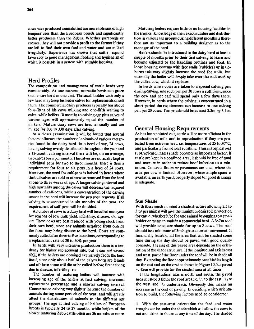
264
cows have produced animals that are more tolerant of high temperatures than the European breeds and significantly better producers than the Zebus. Whether purebreds or crosses, they will not provide a profit to the farmer if they are left to find their own feed and water and are milked irregularly. Experience has shown that cattle respond favorably to good management, feeding and hygiene all of which is possible in a system with suitable housing.
Herd Profiles The composition and management of cattle herds vary considerably. At one extreme, nomadic herdsmen graze then entire herd as one unit. The small holder with only a few head may keep his heifer calves for replacements or sell them. The commercial dairy producer typically has about four-fifths of his cows milking and one-fifth waiting to calve, while heifers 10 months to calving age plus calves of various ages will approximately c-qua1 the number of milkers. Mature dairy cows are bred annually and are milked for 300 to 330 days after calving.
At a closer examination it will be found that several factors influence the number of animals of various catego- ries found in the dairy herd. In a herd of say, 24 cows, having calving evenly distributed throughout the year and a IZmonth calving interval there will be, on an average, two calves born per month. The calves are normally kept in individual pens for two to three months, there is thus a requirement for four to six pens in a herd of 24 cows. However, the need for calf-pens is halved in herds where the bull calves are sold or otherwise removed from the herd at one to three weeks of age. A longer calving interval and high mortality among the calves will decrease the required number of calf-pens, while a concentration of the calving season in the herd will increase the pen requirements. If all calving is concentrated in six months of the year, the requirement of calf-pens will be doubled.
A number of cows in a dairy herd will be culled each year for reasons of low milk yield, infertility, disease, old age, etc. These cows are best replaced with young stock from their own herd, since any animals acquired from outside the farm may bring disease to the herd. Cows are com- monly culled after three to five lactations, corresponding to a replacement rate of 20 to 30% per year.
In herds with very intensive production there is a ten- dency for higher replacement rate, but it can no! exceed 4O%, if the heifers are obtained exclusively from the herd itself, since only about half of the calves born are female and of these some will die or be culled before first calving due to disease, infertility, etc.
The number of maturing heifers will increase with increasing age of the heifers at first calving, increased replacement percentage and a shorter calving interval. Concentrated calving may slightly increase the number of animals during some perixis of the year, and will greatly affect the distribution of animals to the different age groups. The age at first calving of heifers of European breeds is typically 24 to 27 months, while heifers of the slower maturing Zebu cattle often are 36 months or more.
Maturing heifers require little or no housing facilities in the tropics. Knowledge of their exact number and distribu- tion in various age groups during different months is there- fore not as important to a building designer as to the manager of the herd.
Heifers should be introduced in the dairy herd at least a couple of months prior to their first calving to learn and become adjusted to the handling routines and feed. In loose housing systems with free stalls (cubicles) or in tie- barns this may slightly increase the need for stalls, but normally the heifer will simply take over the stall used by the culled cow, which it replaces.
In herds where cows are taken to a special calving pen during calving, one such pen per 30 cows is sufficient, since the cow and her calf will spend only a few days there. However, in herds where the calving is concentrated in a short period the requirement can increase to one calving pen per 20 cows. The pen should be at least 3.3m by 3.3m.
General Housing Requirements As has been pointed out, cattle will be more efficient in the production of milk and in reproduction if they are pro- tected from extreme heat, i.e. temperatures of 25 to 30°C, and particularly from direct sunshine. Thus in tropical ncd subtropical climates shade becomes an important factor. If cattle are kept in a confined area, it should be free of mud and manure in order to reduce hoof infection to a min- imum. Concrete floors or pavements are ideal where the area per cow is limited. However, where ample space is available, an earth yard, properly sloped for good drainage is adequate.
Sun Shade With these needs in mind a shade structure allowing 2.5 to 3mz per animal will give the minimum desirable protection for cattle, whether it be for one animal belonging to a small holder or many animals in acommercial herd. A 3X7m roof will provide adequate shade for up to 8 cows. The roof should be a minimum of 3m high to allow air movement. If financially feasible, all the area that will be shaded some time during the day should be paved with good quality concrete, The size of this paved area depends on the orien- tation of the shade structure. !fthe !ongitudinal axis is east and west, part of the floor under the roof will be in shade all day. Extending the floor approximately one third its length on the east and on the west as shown in Figure 10.3, a paved surface will provide for the shaded area at all times.
If the longitudinal axis is north and south, the paved area must-be 3 times the roof area i.e. l/3 to the east, l/3 to the west and l/3 underneath. Obviously this means an increase in the cost of paving. In deciding which orienta- tion to build, the following factors need be considered:
1 With the east-west orientation the feed and water troughs can be under the shade which will allow the cows to eat and drink in shade at any time of the day. The shaded
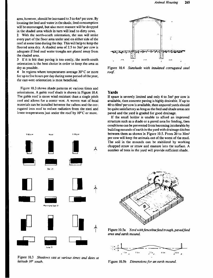
Animal Housing 265
area, however, should be increased to 3 to 4m2 per cow. By locating the feed and water in the shade, feed consumption will be encouraged, but also more manure will be dropped in the shaded area which in turn will lead to dirty cows. 2 With the north-south orientation, the sun will strike every part of the floor area under and on either side of the roof at some time during the day. This wiil help to keep the floored area dry. A shaded area of 2.5 to 3m2 per cow is adequate if feed and water troughs are placed away from the shaded area. 3 If it is felt that paving is too costly, the north-south orientation is the best choice in order to keep the area as dry as possible. 4 In regions where temperatures average 30°C or more for up to five hours per day during some period of the year, the east-west orientation is most beneficial.
Figure 10.3 shows shade patterns at various times and orientations. A gable roof shade is shown in Figure 10.4. The gable roof is more wind resistant than a single pitch roof and allows for a center vent. A woven mat of local materials can be installed between the rafters and the car-, rugated iron roof to reduce radiation from the steel and lower temperatures just under the roof by 10°C or more.
3 OOpm
a
Figure 10.3 Shadows cast at various times and dares at latitude InO south.
Figure 10.4 S&shade with insulated corrugated steel roof:
Yards If space is severely limited and only 4 to 5m2 per cow is available, then concrete paving is highly desirable. If up to 40 to 6Om* per cow is available, then unpaved yards should be quite satisfactory as long as the feed and shade areas are paved and the yard is graded for good drainage.
If the small holder is unable to afford an improved structure such as a shade or a paved area for feeding, then conditions can be prevented from becoming intolerable by building mounds of earth in the yard with drainage ditches between them as shown in Figure 10.5. From 20 to 30m2 per cow will keep the animals out of the worst of the mud. The soil in the mounds can be stabilized by working chopped straw or straw and manure into the surface. A number of trees in the yard will provide sufficient shade.
Figure IOSa Yard with fencelinefeed trough, pavedfeed area and earth mound.
JOrF 8 on :om 0 om 30m + , l e -..-...--.--_. t
Figure 10Sb Dimensions for an earth mound.
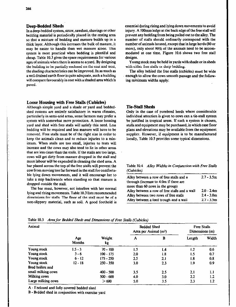
266
Deep-Bedded Sheds In a deep-bedded system, straw, sawdust, shavings or other bedding material is periodically placed in the resting area so that a mixture of bedding and manure builds up in a thick layer. Although this increases the bulk of manure, it may be easier to handle than wet manure alone. This system is most practical when bedding is plentiful and cheap. Table 10.3 gives the space requirements for various ages of animals when there is access to a yard. By designing the building to be partially enclosed on the east and west, the shading characteristics can be improved. In as much as a well drained earth floor is quite adequate, such a building will compare favourably in cost with a shaded area which is paved.
Loose Housing with Free Stalls (Cubicles) Although simple yard and a shade or yard and bedded- shed systems are entirely satisfactory in warm climates, particularly in semi-arid areas, some farmers may prefer a system with somewhat more protection. A loose housing yard and shed with free stalls will satisfy this need. Less bedding will be required and less manure will have to be removed. Free stalls must be of the right size in order to keep the animals clean and to reduce injuries to a min- imum. When stalls are too small, injuries to teats will increase and the cows may also tend to lie in other areas that are less clean than the stalls. If the stalls are too large, cows will get dirty from manure dropped in the stall and more labour will be expended in cleaning the shed area. A bar placed across the top of the free stalls will prevent the cow from moving too far forward in the stall for comforta- ble lying down movements, and it will encourage her to take a step backwards when standing so that manure is dropped outside the stall.
The bar must, however, not interfere with her normal lying and rising movements. Table 10.3 lists recommended dimensions for stalls. The floor of the stall must be of a non-slippery material, such as soil. A good foothold is
essential d.uring rising and iying down movements to avoid injury. A IOOmm ledge at the back edge of the free stall will’ prevent any bedding from being pulled out to the alley. The number of stalls should ordinarily correspond with the number of animals housed, except that in large herds (80 or more), only about 90% of the animals need to be accom- modated at one time. Figure 10.6 shows two free stall designs.
Young stock may be held in yards with shade or in sheds with either free stalls or deep bedding.
The alley behind the free stalls (cubicles) must be wide enough to allow the cows smooth passage and the follow- ing minimum widths apply:
Tie-Stall Sheds Only in the case of purebred herds where considerable individual attention is given to cows can a tie-stall system be justified in tropical areas. If such a system is chosen, stalls and equipment may be purchased, in which case floor plans and elevations may be available from the equipment supplier. However, if equipment is to be manufactured locally, Table 10.5 provides some typical dimensions.
Table 10.4 Alley Widths in Conjunction with Free Stalls (Cubicles)
Alley between a row of free stalls and a through (increase to 4.0m if there are more than 60 cows in the group) Alley between a row of free stalls and a wall Ailey between two rows of free stalls Alley between a feed trough and a wall
2.7 - 3.Sm
2.0 - 2.4m 2.4 - 3.0m 2.7 - 3.Sm
Table 10.3 Area for Bed&d She& and Dimensions of Free Stalls (Cubicles)
Animal Bedded Shed Area per Animal (mz)
Age Weight A B Months kg
Young stock 1.5-3 70-m 1.5 1.4 Young stock 3-6 100 - 175 2.0 1.8 Young stock 6-12 175 - 250 2.5 2.1 Young stock 12-18 250-350 3.0 2.3 Bred heifers and small milking cows 400-500 3.5 2.5 Milking cows 500-600 4.0 3.0 Large milking cows >650 5.0 3.5
A - Enclosed and fully covered bedded shed B - &dded shed in conjunction with exercise yard
Free Stalls Dimensions (m)
Length Width
1.2 0.6 1.5 0.7 1.8 0.8 1.9 0.9
2.1 1.1 2.2 1.2 2.3 1.2
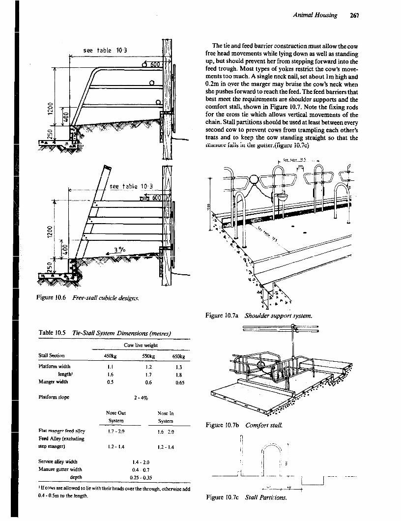
Animal Housing 267
see table IO.3
see table 10.3 .- _- ..-..-..- ~__
-- . I-L! - .
. .
8 c l .
a- -
Figure 10.6 Free-srali cubicle desigtx
Table IO.5 Tie-Stail System Dimensions (metres)
Cow live weight
Stall Section 450kg
Platform width I.1
length’ 1.6
Manger width 0.3
33Okg 6SOkg
1.2 1.3
1.7 1.8
0.6 0.65
Platform slope 2-49-b
Flat manger feed alley
Feed Alley (excluding
step manger)
Nose Out
System
I.7 - 2.0
1.2 - 1.4
Nose In
System
1.6-2.0
I.2 - 1.4
Serwa alley width 1.4-2.0
Manure gutter width 0.4 0.7
depth 0.25 - 0.35
’ lfcows are allowed to lie with their heads over the through, otherwise add
0.4 - 0.5m to the length.
The tie and feed barrier construction must allow the cow free head movements while lying down as well as standing up, but should prevent her from stepping forward into the feed trough. Most types of yokes restrict the cow’s move- ments too much. A single neck nail, set about 1 m high and 0.2m in qver the marger may bruise the cow’s neck when she pushes forward to reach the feed. The feed barriers that best meet the requirements are shoulder supports and the comfort stall, shown in Figure 10.7. Note the fling rods for the cross tie which allows vertical movements of the chain. Stall partitions should be used at least between every second cow to prevent cows from trampling each other’s teats and to keep the cow standing straight so that the manure falls in the gutter.(figure 10.7~)
Figure 10.7a Shoulder support system.
Figure I0.7b Comfort stall.
f..!’ --y--i---- i
Figure 10.7~ Stall Partivions.
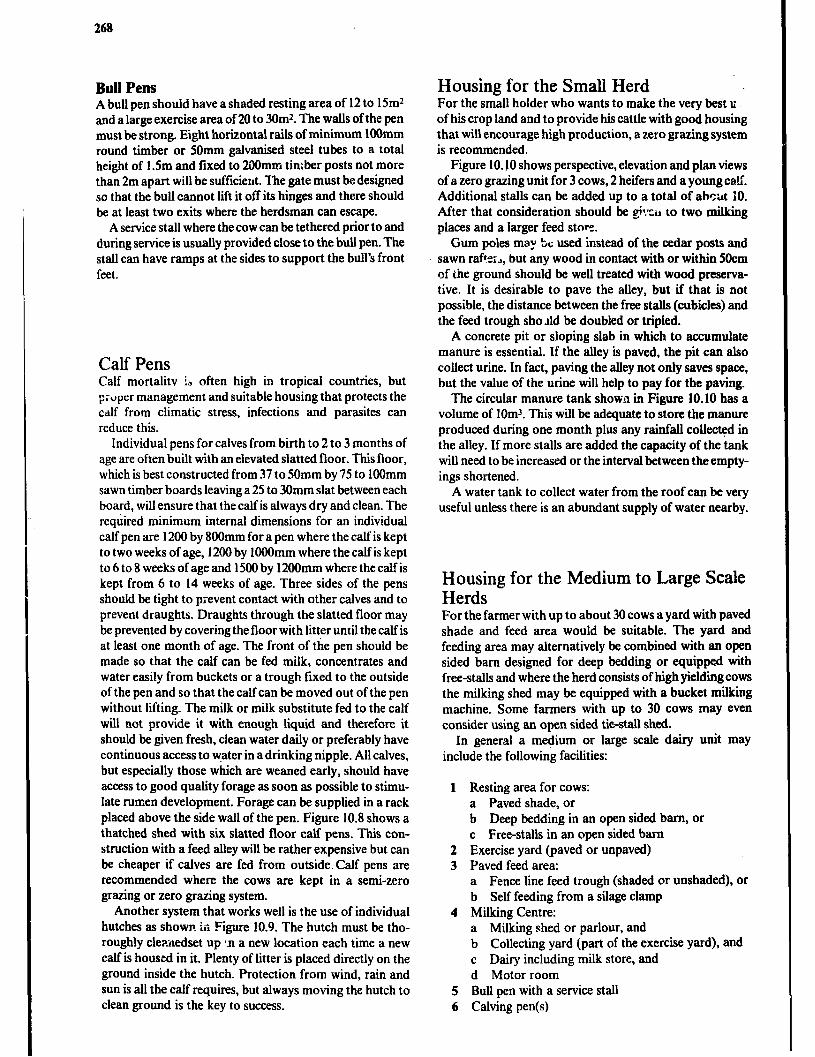
268
Bull Pens A bull pen should have a shaded resting area of 12 to 15mZ and a large exercise area of 20 to 3Om2. The walls of the pen must be strong. Eight horizontal rails of minimum 1OOmm round timber or 5Omm galvanised steel tubes to a total height of 1.5m and fured to 2OOmm timber posts not more than 2m apart will be sufficient. The gate must be designed so that the bull cannot lift it off its hinges and there should be at least two exits where the herdsman can escape.
A service stall where the cow can be tethered prior to and during service is usually provided close to the bull pen. The stall can have ramps at the sides to support the bull’s front feet.
Calf Pens Calf mortalitv i, often high in tropical countries, but p:tiprr management and suitable housing that protects the calf from climatic stress, infections and parasites can reduce this.
Individual pens for calves from birth to 2 to 3 months of age are often built with an elevated slatted floor. This floor, which is best constructed from 37 to 50mm by 75 to 1OOmm sawn timber boards leaving a 25 to 30mm slat between each board, will ensure that the calf is always dry and clean. The required minimum internal dimensions for an individual calf pen are 1200 by 800mm for a pen where the calf is kept to two weeks of age, 1200 by 1OOOmm where the calf is kept to 6 to 8 weeks of age and 1500 by 1200mm where the calf is kept from 6 to 14 weeks of age. Three sides of the pens should be tight to prevent contact with other calves and to prevent draughts. Draughts through the slatted floor may be prevented by covering the floor with litter until the calf is at least one month of age. The front of the pen should be made so that the calf can be fed milk, concentrates and water easily from buckets or a trough fixed to the outside of the pen and so that the calf can be moved out of the pen without lifting. The milk or milk substitute fed to the calf will not provide it with enough liquid and therefore it should be given fresh, clean water daily or preferably have continuous access to water in a drinking nipple. All calves, but especially those which are weaned early, should have access to good quality forage as soon as possible to stimu- late rumen development. Forage can be supplied in a rack placed above the side wall of the pen. Figure 10.8 shows a thatched shed with six slatted floor calf pens. This con- struction with a feed alley will be rather expensive but can be cheaper if calves are fed from outside. Calf pens are recommended where the cows are kept in a semi-zero grazing or zero grazing system.
Another system that works well is the use of individual hutches as shown. in Figure 10.9. The hutch must be tho- roughly clepaedset up 1.n a new location each time a new calf is housed in it. Plenty of litter is placed directly on the ground inside the hutch. Protection from wind, rain and sun is ail the calf requires, but always moving the hutch to clean ground is the key to success.
Housing for the Small Herd For the small holder who wants to make the very best u of his crop land and to provide his cattle with good housing that will encourage high production, a zero grazing system is recommended.
Figure 10.10 shows perspective, elevation and plan views of a zero grazing unit for 3 cows, 2 heifers and a young calf. Additional stalls can be added up to a total of abottt 10. After that consideration should be @:cir to two milking places and a larger feed stny.
Gum poles may LYc used instead of the cedar posts and sawn r&53, but any wood in contact with or within 5Ocm of the ground should be well treated with wood preserva- tive. It is desirable to pave the alley, but if that is not possible, the distance between the free stalls (cubicles) and the feed trough sho Ad be doubled or tripled.
A concrete pit or sloping slab in which to accumulate manure is essential. If the alley is paved, the pit can also collect urine. In fact, paving the alley not only saves space, but the value of the urine will help to pay for the paving.
The circular manure tank shown in Figure 10.10 has a volume of lOm3. This will be adequate to store the manure produced during one month plus any rainfalI collected in the alley. If more stalls are added the capacity of the tank will need to be increased or the interval between the empty- ings shortened.
A water tank to collect water from the roof can be very useful unless there is an abundant supply of water nearby.
Housing for the Medium to Large Scale Herds For the farmer with up to about 30 cows a yard with paved shade and feed area would be suitable. The yard and feeding area may alternatively be combined with an open sided barn designed for deep bedding or equipped with free-stalls and where the herd consists of high yielding cows the milking shed may be equipped with a bucket milking machine. Some farmers with up to 30 cows may even consider using an open sided t&stall shed.
In general a medium or large scale dairy unit may include the following facilities:
1 Resting area for cows: a Paved shade, or b Deep bedding in an open sided barn, or c Free-stalls in an open sided barn
2 Exercise yard (paved or unpaved) 3 Paved feed area:
a Fence line feed trough (shaded or unshaded), or b Self feeding from a silage clamp
4 Milking Centre: a Milking shed or parlour, and b Collecting yard (part of the exercise yard), and c Dairy including milk store, and d Motor room
5 Bull pen with a service stall 6 Calving pen(s)
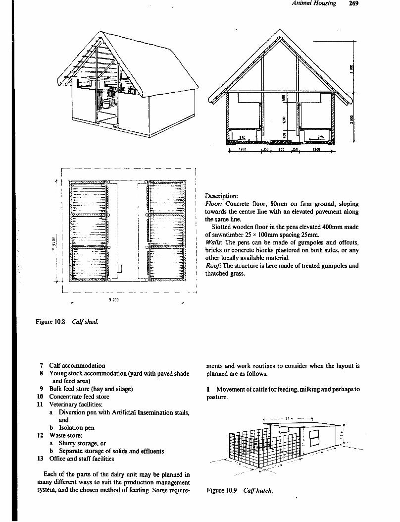
Animal Housing 269
Figure 10.8
~.- -- --- _ _- _- _- _ _
c 3 900
*
Calf shed.
Description: Floor: Concrete floor, 80mm on firm ground, sloping towards the centre line with an elevated pavement along the same line.
Slotted wooden floor in the pens elevated 400mm made of sawntimber 25 x 1OOmm spacing 25mm. Walls: The pens can be made of gumpoles and offcuts, bricks or concrete blocks plastered on both sides, or any other locally available material. Roe) The structure is here made of treated gumpoles and thatched grass.
7 Calf accommodation 8 Young stock accommodation (yard with paved shade
and feed area) 9 Bulk feed store (hay and silage)
10 Concentrate feed store 11 Veterinary facilities:
a Diversion pen with Artificial Insemination stalls, and
b Isolation pen 12 Waste store:
a Shu-ry storage, or b Separate storage of solids and effluents
13 Oftice and staff facilities
Each of the parts of the dairy unit may be planned in many different ways to suit the production management system, and the chosen method of feeding. Some require-
ments and work routines to consider when the layout is planned are as follows:
1 Movement of cattle for feeding, milking and perhaps to pasture.
t --~ ---2Om ---7
__---
-._.
Figure 10.9 Calfhutch.

270
n
C
r----- ---.---- L----y--- ---- ---1 T
Figure 10.10 Zero grazing system for rhe small holder.

2 Movement of bulk feed from store to feeding area and c-dncentrates from store to milking shed or parlour. 3 Transfer of milk from milking shed or parlour to dairy and then off the farm. Clean and dirty activities, such as milk handling and waste disposal, should be separated as far as possible. 4 The diversion pen with Artificial Insemination stalls and any bull pen should be close to the milki ‘Ig centre as any symptoms of heat or illness are commonly discovered durizlg milking and cows are easily separated from the rest af the herd while leaving the milking. 5 Easy and periodical c:a,sning of accommodation, yards, milking facilities and dairy, and transfer of the waste to storage and then to the fields. 6 The movements of the herdsman. Minimum travel to move cows in or out of milking area. ‘7 Provision for future expansion of the various parts of the unit.
Milking md Milk Handling
Hand Milking YS. Machine Milking In developed courtries, where labour is scarce and expen- sive, machine miting has become very widespread and it is
r --- -- 1 I I 1
1 I I
i
Animal Housing 271
also practised on many large commercial dairy farms in the tropics. Milking machines not only reduces labour requirement and eliminates the drudgery of hand milking, but in most cases performs a better quality milking opera- tion than would be done by hand. However, most of the many small dairy farms in developing countries have a surplus of cheap labour and the number of cows milked at each of them is not sufficient to economically justify the installation of a machine. Furthermore, machines require power and are more expensive to purchase then the few pieces of equipment needed for hand milking. In many developing countries there is an irregular supply of spare parts and a lack of skilled mechanics.
Machine Milking gives a good quality and operates with a uniform vacuum of 275 - 350mm of mercury, provides a massaging effect on the teats, and is easdy cleaned. The milking machine simulates nursing by the calf. Two vacuum lines lead to the teat cups. A pulsator supplies an intermittent vacuum to one line at the rate of 45 to 60 pulses per minute. The line, connected to the shell of the teat cup, causes the teat inflation (rubber liner) to alter- nately expand and collapse. This massaging action pro- motes normal blood circulation in the teat. The second line maintains a continuous vacuum on the teat and carries the milk either to a stainless steel bucket or through a pipeline &rectly to the milk cooler.
Feed alley
------------------9
Free stalls
Concentrate 0 Storage
0 -a-
Manure
Figure 10.11 &sic sketch of a layout for a medium to large scale dairy unit, showing the relative.location of the various parts and a suggestion for extension. (Not drawn to scale).
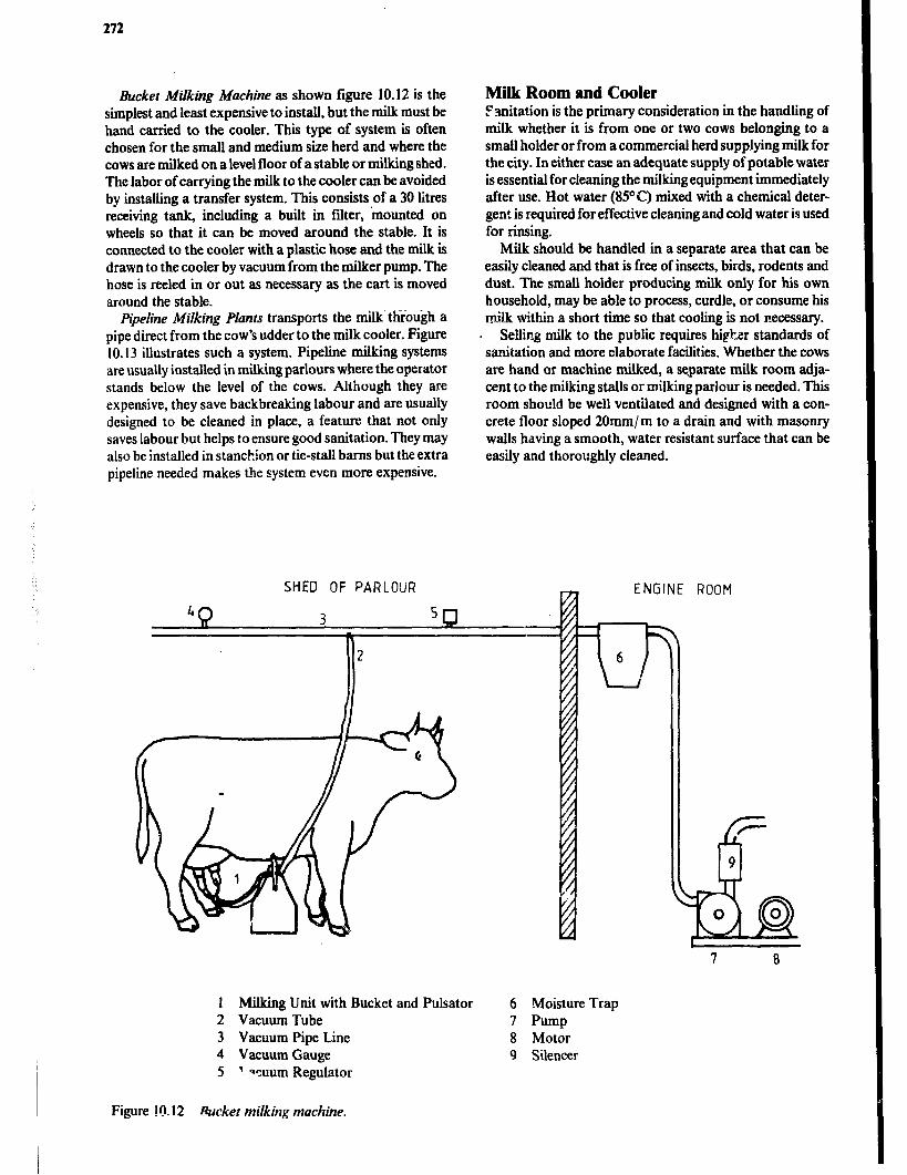
272
Bucket Milking Machine as shown figure 10.12 is the simplest and least expensive to install, but the milk must be hand carried to the cooler. This type of system is often chosen for the small and medium size herd and where the cows are milked on a level floor of a stable or milking shed. The labor of carrying the milk to the cooler can be avoided by installing a transfer system. This consists of a 30 litres receiving tank, including a built in filter, ‘mounted on wheels so that it can be moved around the stable. It is connected to the cooler with a plastic hose and the milk is drawn to the cooler by vacuum from the milker pump. The hose is reeled in or out as necessary as the cart is moved around the stable.
Pipeline MiIking Plants transports the milk. through a pipe direct from the cow’s udder to the milk cooler. Figure 10.13 illustrates such a system. Pipeline milking systems are usually installed in milking parlours where the operator stands below the level of the cows. Although they are expensive, they save backbreaking labour and are usually designed to be cleaned in place, a feature that not only saves labour but helps to ensure good sanitation. They may also be installed in stanchion or tie-stall barns but the extra pipeline needed makes the system even more expensive.
Milk Room and Cooler Pvlitation is the primary consideration in the handling of milk whether it is from one or two cows belonging to a small holder or from a commercial herd supplying milk for the city. In either case an adequate supply of potable water is essential for cleaning the milking equipment immediately after use. Hot water (85” C) mixed with a chemical deter- gent is required for effective cleaning and cold water is used for rinsing.
Milk should be handled in a separate area that can be easily cleaned and that is free of insects, birds, rodents and dust. The small holder producing milk only for his own household, may be able to process, curdle, or consume hi milk within a short time so that cooling is not necessary.
. Selling milk to the public requires hi&r standards of sanitation and more elaborate facilities. Whether the cows are hand or machine milked, a separate milk room adja- cent to the milking stalls or milking parlour is needed. This room should be well ventilated and designed with a con- crete floor sloped 20mm/m to a drain and with masonry walls having a smooth, water resistant surface that can be easily and thoroughly cleaned,
SHED OF PARLOUR ENGINE ROOM
-
1 Milking Unit with Bucket and Pulsator 6 Moisture Trap 2 Vacuum Tube 7 Pump 3 Vacuum Pipe Line 8 Motor 4 Vacuum Gauge 9 Silencer 5 ’ qcuum Regulator
Figure !(1. I2 Bucket milking machine.
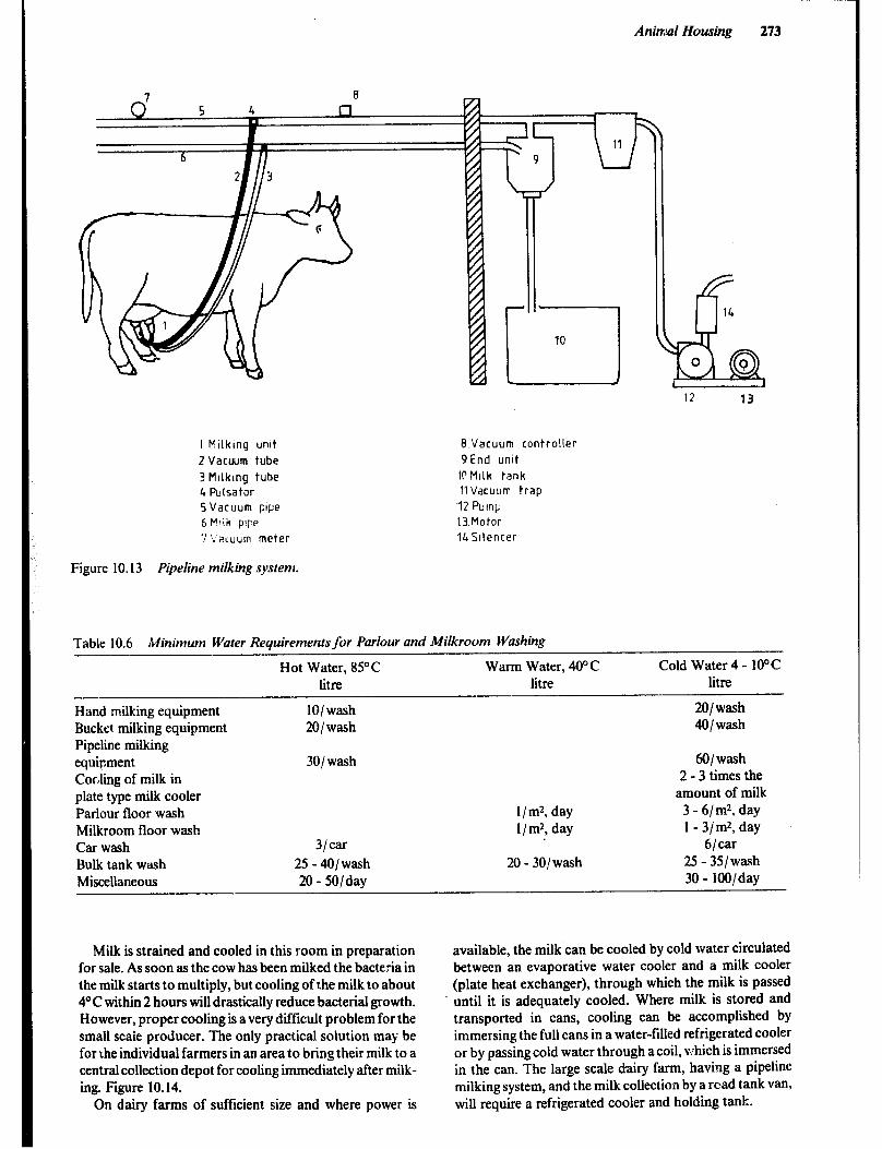
Animal Housing 273
12 13
I Milking unit 8 Vacuum controller
2 Vacuum tube 9End unit
3 Mllklng tube 10Mllk tank
4 Pulsator II Vacuum trap
5 Vacuum pipe ‘12 PuinC
6 Fclik pip? 13.Motor
7 ‘r’akuum meter 14 Silencer
Figure 10.13 Pipeline milking system.
Table 10.6 Minimum Water Requirements for Parlour and Milkroom Washing
Hot Water, 85°C Warm Water, 40” C litre litre
Hand milking equipment 101 wash Bucket milking equipment 201 wash Pipeline milking equipment 301 wash Cocling of milk in plate type milk cooler Parlour floor wash 1 / m2, day Milkroom floor wash I/ m2, day Car wash 3/tar
Bulk tank wash 25 - 401 wash 20 - 301 wash Miscellaneous 20 - 5O/day
Cold Water 4 - 10°C litre
201 wash 401 wash
601 wash 2 - 3 times the
amount of milk 3 - 6/m2, day 1 - 3/m2, day
6/tar 25 - 351 waqh 30 - lOO/day
Milk is strained and cooled in this room in preparation for sale. As soon as the cow has been milked the bacteria in the milk starts to multiply, but cooling of the milk to about 4OC within 2 hours will drastically reduce bacterial growth. However, proper cooling is a very difficult problem for the small scaie producer. The only practical solution may be for the individual farmers in an area to bring their milk to a central collection depot for cooling immediately after milk- ing. Figure 10.14.
On dairy farms of sufficient size and where power is
available, the milk can be cooled by cold water circulated between an evaporative water cooler and a milk cooler (plate heat exchanger), through which the milk is passed until it is adequately cooled. Where milk is stored and transported in cans, cooling can be accomplished by immersing the full cans in a water-filled refrigerated cooler or by passing cold water through a coil, v:hich is immersed in the can. The large scale dairy farm, having a pipeline milking system, and the milk collection by a road tank van, will require a refrigerated cooler and holding tank.
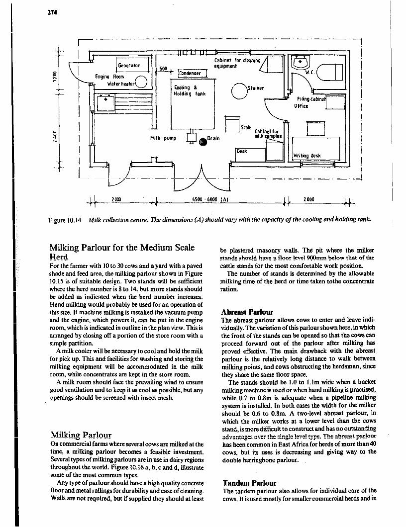
274
np p1 allrain
-.- I/ -.-. -.-. t-~-.-.-.-.-.-.-.-A
-d--- zoo0 .1 14 4500 - 6000 (Al 11 11 2 000 11 11
Figure 10.14 Milk colizxtion centre. The dimensions {A) should vary wirh the capacity of the cooling and holding tank.
Milking Parlour for the Medium Scale Herd For the farmer with 10 to 30 cows and a yard with a paved shade and feed area, the milking parlour shown in Figure 10.15 is of suitable design. Two stands will be sufficient where the herd number is 8 to 14, but more stands should be added as indicated when the herd number increases. Hand milking would probably be used for an operation of this size. If machine milking is installed the vacuum pump and the engine, which powers it, can be put in the engine room, which is indicated in outline in the plan view. This is arranged by closing off a portion of the store room with a simple partition.
A milk cooler will be necessary to cool and hold the milk for pick up. This and facilities for washing and storing the milking equipment will be accommodated in the milk room, while concentrates are kept in the store room.
A milk room should face the prevailing wind to ensure good ventilation and to keep it as cool as possible, but any openings should be screened with insect mesh.
Milking Parlour On commercial farms where several cows are milked at the time, a milking p&our becomes a feasible investment. Several types of milking parlours are in use in dairy regions throughout the world. Figure 12.16 a, b, c and d, illustrate some of the most common types.
Any type of parlour should have a high quality concrete floor and metal railings for durability and ease of cleaning. Walls are not required, but if supplied they should at least
be plastered masonry walls. The pit where the milker stands should have a floor level 9OOmm below that of the cattle stands for the most comfortable work position.
The number of stands is determined by the allowable milking time of the herd or time taken tothe concentrate ration,
Abreast Parlour The abreast parlour allows cows to enter and leave indi- vidually. The variation of this parlour shown here, in which the front of the stands can be opened so that the cows can proceed forward out of the parlour after milking has proved effective. The main drawback with the abreast. parlour is the relatively long distance to walk between milking points, and cows obstructing the herdsman, since they share the same floor space.
The stands should be 1.0 to l.lm wide when a bucket milking machine is used or when hand milking is practised, while 0.7 to 0.8m is adequate when a pipeline milking system is installed. In both cases the width for the milker should be 0.6 to 0.8m. A two-level abreast parlour, in which the milker works at a lower level than the cows stand, is more difficult to construct and has no outstanding advantages over the single level type. The abreast parlour has been common in East Africa for herds of more than 40 cows, but its uses is decreasing and giving way to the double herringbone parlour.
Tandem Parlour The tandem parlour also allows for individual care of the cows. It is used mostly for smaller commercial herds and in
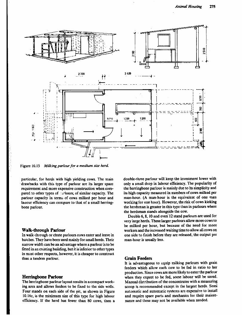
Animal Housing 275
H
Figure 10.15 Milking parlour for a medium size herd.
particular, for herds with high yielding cows. The main ‘drawbacks with this type of parlour are its larger space requirement and more expensive construction when com- pared to other types of !..~rlours; of similar capacity. The parlour capacity in terms of cows milked per hour and laoour efficiency can compare io that of a small herring- bone parlour.
Walk-tbroqgh Parhr In walk-through or chute parlours cows enter and leave in batches. They have been used mainly for small herds. Their narrow width can be an advantage where a parlour is to be fitted in an existing building, but it is inferior to other types in most other respects, however, it is cheaper to construct than a tandem parlour.
Herringbone Parlour The herringbone parlour layout results in a compact work- ing area and allows feeders to be fixed to the side walls. Four stands on each side of the pit, as shown in Figure lO.l6c, is the minimum size of this type for high labour efficiency. If the herd has fewer than 80 cows, then a
double-three parlour will keep the investment lower with only a small drop in labour efficiency. The popularity of the herringbone parlour is mainly due to its simplicity and its high capacity measured in numbers of cows milked per man-hour. (A man-hour is the equivalent of one man working for one hour). However, the risk of cows kicking the herdsman is greater in this type than in parlours where the herdsman stands alongside the cow.
Double 6,8,10 and even 12 stand parlours are used for very large herds. These larger parlours allow more cows to be milked per hour, but because of the need for more workers and the increased waiting time to allow all cows on one side to finish before they are released, the output per man-hour is usually less.
Grain Feeders It is advantageous to equip milking parlours with grain feeders which allow each cow to be fed in ratio to her production. Since cows are more likely to enter the parlour when they expect to be fed, some labour will be saved. Manual distribution of the concentrates with a measuring scoop is recommended except in the largest herds. Semi automatic and automatic systems are expensive to install and require spare parts and mechanics for their mainte- nance and these may not be available when needed.
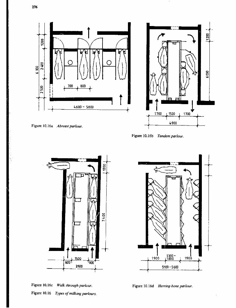
4600 - 5800 1 1
Figure IO. I6a Abreast parlour.
- 1700 L1500 1 1700 L
I 1 1 1
--t- 4900 1
1
Figure 10.16b Tandemparlour.
- -
1 1 1 1 1 1 1 1
1 5100-5600 1
j
Figure 10.16~ Walk rhrough purlour.
Figure 10.16 Types of milking parlours.
Figure IO. 16d Herring-bone p&our.

Animal Housing 277
Collecting Yard The cows are normally assembled in a collecting yard (holding area) before milking. This may be a portion of the yard that is temporarily fenced off with chains. The collect- ing yard should have a minimum size of 1.1 to 2.0m2 per cow. Large horned cows and a low herd number will require the largest space per cow. Provision must be made for water for the cows awaiting their turn to enter the parlour. The areashould slope away from the parlour 20 to lOOmm/m. This not only improves drainage, but also encourages the cows to face the entrance.
The collecting yard should be paved for easy cleaning and to allow for sanitary conditions in the parlour. A roof is desirable for shade and to avoid wet cows entering the parlour in the rainy season and it wil! reduce the amount of rainwater that has to be stored in the manure pit.
Entrance and Exit An entrance into the parlour that is straight (no turns) will ensure a smooth and convenient operation. Once trained, cows and heifers will walk readily into the parlour. A single step of about IOOmm will help to keep manure from being carried into the parlour.
An exit leading into an uncrowded area will facilitate animal flow. A straight exit is desirable but not as impor- tant as a straight entry. If exiting alleys are needed they should be narrow (700 tc !IOOmm depending on cow size), to keep the cows from turning around.
Feeding Equipment One advantage of loose housing of cattle is the opportunity to construct the feed trough in the fence allowing easy access for filling. The simplest type of manger consists of a low barrier with a rail fixed above. However, cattle have a tendency to throw feed forwards while eating, but a wall in front, as shown in Figure 10.18, will reduce this problem. The dimensions of the trough must be chosen to conform with the height, reach and required width of the feeding space for the animals to be fed, while providing enough volume for the amount of feed distributed at each feeding time. Figures 10.17, 10.18 and lO.i9.
Although timber construction is simple to install, con- crete should be considered because of its greater durability. When timber is used, the base should be well treated with wood preservative. However, the preservative should not be used on any surface which cattle can reach to lick as some preservative materials are toxic to animals. When concrete is used, it should be a! least C20, or P nominal mix of 1:2:4; since a lower grade concrete would soon deterio- rate due to chemical attack by feed stuffs and the cow’s saliva. The cows will press against the barrier before and during the feeding so that the head rail must be firmly fixed to the vertical posts, which are immovably set in the ground.
A 2.5m wide concrete apron along the feed trough will reduce the accumulation of mud. A narrow step next to the trough will help to keep the trough free of manure as animals will not back up on to such a step. The bottom of the feed trough should be at a level 100 to4OOmm above the level at which the cow is standing with her front feet.
A slightly more elaborate feed trough separates the cattle by vertical rails or tomb stone barriers, as shown in Figure 10.19, to reduce competition during eating. The tombstone barrier may also reduce fodder spillage because the cow has to lift her head before withdrawing it from the trough.
A simple roof constructed over the feed trough and the area where the cows stand to eat will serve as a shade and encourage daytime feeding in bright weather while serving to protect the feed from water damage in rainy periods.
Watering Equipment Drinking water for cattle must be clean. Impurities may disturb the microbiological activities in the rumen. Table 10.7 shows the requirement of drinking water, but a hot environment may considerably increase it. In dairy cows the need for water will increase with milk yield.
A Reach at ground level
B Reach at 300mm above
ground level
C Throught height
D Height to the withers
- Width of feeding space:
when all animals feed at once
feed always available
~- Level of feed trough bottom
above level of stand
calves Heifers
550 650
700
350
loo0
350 - 500 500 - 650 650 - 750
loo I50 220
50-200 100-300 loo-400
850
500
12oa
Mature
cows
700
900
600
I300
Figure 10.17 Dimensionforfeed trough designfor cattle.
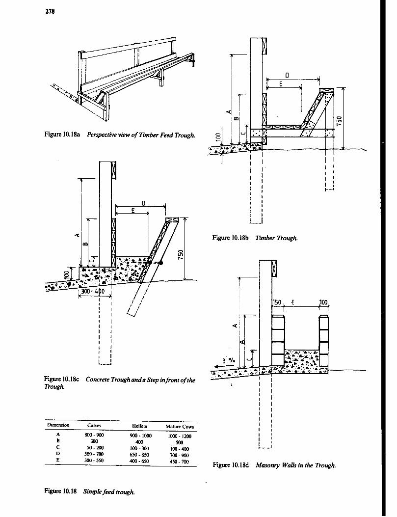
278
Figure 10.18a Perspective view of Zlmber Feed Trough.
Figure 10.18~ Dough.
Concrete Dough and a Step infront of the
Diicnsion calves Heifers Mature Cows
A m-900 WO-1000 looo- 1200 B 300 400 so0 C so-200 100-300 100-400 D m-700 650-850 700-900 E 300-550 400-6M 450-700
Figure 10.18b Timber l’kough.
4 & 3’% u
..*,’ .a,“, .:. & ....b .,( b ,;. ..*. ..A.-
1
Figure 10.18d Walls in the 7kough.
Figure 10.18 Simpk feed trough.
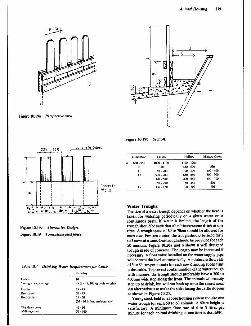
Animal Housing 279
Figure IO. l9a Perspective view.
Concrete pipes $/r---- j225 +225 ,~
Figure IO. l9c Alternative Design.
Figure 10.19 Tombstone feed fence.
Table 10.7 Drkking Water Requirement for Cattle
We/day
GlVeS
Young stock. average
Heifers
Beef cows
Beef cattle
Dry dairy cows
Milking cows
10
25 (8 - 121 IOOkg body weight)
35-45
30-45
15-M
(30 - 60 in hot environment)
40-60
50- 100
<
Figure 10.19b Section.
Dimension Calves Heifers Mature Cows
A 850 -950 Iooo- 1100 Iloo- 1200 B 350 450 - 500 550
C 50-200 100-300 loo-400 D 500-700 650 - 850 700-900
E 300-550 400 - 650 450 - 700
F 150-250 150-450 500
G 130 - 150 170-200 200
Water Troughs The size of a water trough depends on whether the herd is taken for watering periodically or is given water on a continuous basis. If water is limited, the length of the trough should be such that all of the cows can drink at one time. A trough space of 60 to 70cm should be allowed for each cow. For free choice, the trough should be sized for 2 to 3 cows at a time. One trough should be provided for each 50 animals. Figure 10.20a and b shows a well designed trough made of concrete. The length may be increased if necessary. A float valve installed on the water supply pipe will control the level automatically. A minimum flow rate of 5 to 8 litres per minute for each cow drinking at one time is desirable. To prevent contamination of the water trough with manure, the trough should preferably have a 300 to 400mm wide step along the front. The animals will readily step up to drink, but will not back up onto the raised area. An alternative is to make the sides facing the cattle sloping as shown in Figure 10.2Oc.
Young stock held in a loose housing system require one water trough for each 50 to60 animals. A 6Ocm height is satisfactory. A minimum flow rate of 4 to 5 iitres per minute for each animal drinking at one time is desirable.

280
Figure 10.20a Length section.
Figure 10.21 Automatic Drinker.
Dry Hay or Forage If an adequate supply of green forage can be grown throughout the year, then only temporary forage storage
. . ,. tic and space for chopping is required. On the other hand if a prolonged dry season makes it necessary to conserve dry forage, a storage method that will prevent spoilage is essen-
Figure l0.20b Cross section (without step). tial. A raised slatted floor with a thatched or corrugated steel roof will provide good protection for hay. A simple storage similar to the sunshade shown in Figure 10.4 will be adequate.
+!YL+- !wo ~. &EC) If the store is filled gradually, it may help to have some poles in the top of the shed on which to spread hay for final drying before it is packed into the store. Loose hay weighs
requirements will vary hay or other forage per
Figure 10.2oC Alternative cross section.
Figure 10.20 Concrete water trough.
Automatic Drinkers Automatic drinkers which are activated by the animals provide a hygienic means of supplying water for cows and young stock. Figure 10.21. When used in loose housing systems for cows the bowl should be placed at a height of IOOcm and be protected by a raised area beneath it. (ImZ and 150 to 200mm he&h). One bowl should be provided for each 10 to 15 cows.
A nipple drinker without bowl provides the most hygie- nic means of watering for young stock, but most nipples have limited flow rate and can therefore not be used for calves older than 6 months.
Feed Handling The types and quantities of feed stuffs to be handled varies greatly from farm to farm.
Silage Good quality silage is an excellent feed for cattle. However, it is not practical for the small holder with only a few cows because it is difficult to make small quantities of silage without acessive spoilage.
Successfu; silage making starts with the right crop. The entire maize plant including the grain is ideal as it has enough starch and sugar to ferment well. In contrast many grasses and legumes do not ferment well unless a preserva- tive such as molasses is added as the forage is put into the silo.
It takes a good silo to make good silage. The walls must be smooth, air-tight and for a horizontal silo the’ walls should slope about 1:4 so that the silage packs tighter as it settles. The forage to be made into silage should be at about 30 to 50% moisture content and must be chopped finely and then packed tightly into the silo. The freshly placed material must be covered and sealed with a plastic sheet. Failure at any step along the way speils disaster.
The large commercial farmer, with well constructed horizontal or tower silos and the equipment to fill them, has the chance to make excellent feed. However, good management is no less important, regardless of size.

Animal Housing 281
Concentrates and Grains Again the amount to be stored is highly variable. The method of storing is little different from food grains and suitable storage facilities are discussed in Chapter 9.
Manure Handling Careful waste management is needed:
0 to utilize the fertilizing qualities of the manure, urine and other wastes; 0 to maintain good animal health through sanitary facilities; l to avoid pollution of air and water and to provide good hygiene around the farmstead.
The method of disposal depends on the type of wastes being handled. Solids can be stacked and spread on fields at the optimum time of year, while liquids must be collected in a tank and may be spread from tank-wagons.
Manure from a livestock production unit may contain not only faeces and urine, but also straw or other litter materials, spillage from feeding, and water. If silage is produced on the farm, the runoff from the silos should be led to the urine collection tank. Depending on the wilt the amount of eftluent can vary from zero to O.lm3 or more per tonne of silage but normal storage allowance is 0.05 m3 per tonne.
Manure is handled as solid when the dry matter content exceeds 25%. In this condition the manure can be stacked up to a height of 1.5 to 2 metres. This condition of the manure is only obtained when urine is drained away immediately and a prescribed amount of litter, like straw or sawdust, is used. The use of 1 to 2Skg of litter per cow per
day will ensure that the manure can be handled as a solid. Manure with less than 20% solids has the consistency of
thick slurry. It must be collected in a tank or pit but is too thick to handle effectively with pumps. It must be diluted with water to less than 15% solids before it can be pumped with a conventional centrifugal pump. If diluted in order to use irrigation equipment for spreading liquid manure, the solids must be below 4%.
The amount of manure as well as the composition varies depending upon factors such as feeding, milk yield, animal weight, position in the lactation period, and health of the animal. Cattle fed on ‘wet’ silages or grass produce mr;e urine. Table 10.8 shows the manure production in relation to the weight of the animals. To estimate the volume of manure and bedding, add the volume of manure from Table 10.8 to half the volume of bedding used. I$eavy rains requires removal of liquid for stacked manure, within the storage period. Similarly the storage capacity must be increased by about 5% or a roof should be built over the storage when slurry or liquid manure.
Example
Find suitable dimensions for a slurry manure pit with access ramp given the following:
Animals: 5 dairy cows 5OOkg Storage period: 30 days Maximum slope of access ramp: 15%
Storage capacity (V) needed (see Table 10.8);
V = 5 x 30 x 0.055 = 8.25mr
Table 10.8 Manure Production in Cattle
Weight of animal FaeEs Urine Total Manure Storage capacity to be allow* kg kg/ day kg/ day kg/day m3/ day
Dairy cattle 50 2.7 1.2 3.9 0.004
100 5.2 2.3 7.5 0.009 250 14 6 20 0.025 400 23 10 33 0.045 600 35 15 50 0.065
Beef cattle 350 15 6 21 0.025 450 19 8 27 0.035 550 24 10 34 0.045
* These values are for manure only - no bedding is including. Washing water used in the milking parlour may amount up to 300 litres/stall/milking. Usually 50 lures/head/day to allowed. OVormsl variation can be as much as f20% of the tabled figures).

282
Assume the pit will be 0.5m deep and 5m long, see sketch
Total width (W) will then be:
Cattle Dips Ticks continue to be one of the most harmful livestock pests in East Africa. As vectors of animal diseases ticks have been a great hindrance to livestock development especially in areas where breeds of cattle exotic to the environment have been introduced.
At present the only effective method of control for most of these diseases is control of the vector ticks. Dipping or spraying with an acaricide is the mose efficient way of reducing the number of ticks.
V w q (/I + 0.512) h
h 0.5 12 = 0.1~ = 0.15 = 3.3m
II q I - 12 = 5 - 3.3 = 1.7m
w = (I .7 + O.,“Z.,) 0.5 = 4.9m
A pit 5 x 5 x 0.5m with a slope on the access ram of 15% is chosen.
Siting a Dip The ground where a dip is to be built, and the area around should be slightly sloping and as hard as possible, but not so rocky that a ho!e for the dip cannot be dug. L.aterite (murram) soil is ideal: The ground must:
l support the structure of the dip; 0 be well drained and not muddy in wet weather, and l be resistant to erosion, or gullying of cattle tracks.
Cattle must not be hot or thirsty when they are dipped, so it is important to have a water trough inside the collect- ing yard fence.
Figure 10.22 Manure pit with access ramp.
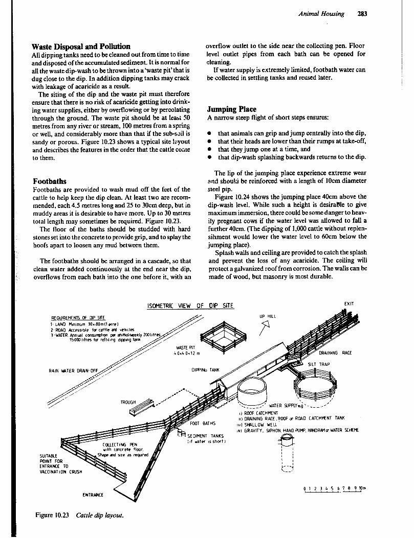
Animal Housing 283
Waste Disposal and Pollution All dipping tanks need to be cleaned out from time to time and disposed of the accumulated sediment. It is normal for all the waste dip-wash to be thrown into a’waste pit’that is dug close to the dip. In addition dipping tanks may crack with leakage of acaricide as a result.
The siting of the dip and the waste pit must therefore ensure that there is no risk of acaricide getting into drink- ing water supplies, either by overflowing or by percolating through the ground. The waste pit should be at least SO metres from any river or stream, 100 metres from a spring or well, and considerably more than that if the sub-s&l is sandy or porous. Figure 10.23 shows a typical site layout and describes the features in the order that the cattle CGiAe to them.
Footbaths Footbaths are provided to wash mud off the feet of the cattle to help keep the dip clean. At least two are recom- mended, each 4.5 metres long and 25 to 30cm deep, but in muddy areas it is desirable tG have more. Up to 30 metres total length may sometimes be required. Figure 10.23.
The flOGr of the baths should be studded with hard stones set into the concrete to provide grip, and to splay the hoofs apart to loosen any mud between them.
The footbaths should be arranged in a cascade, so that clean water added continuously at the end near the dip, overflows from each bath into the one before it, with an
REQIJIREMENTS CF q P SITE
overflow outlet to the side near the collecting pen. Floor level outlet pipes from each bath can be opened for cleaning.
If water supply is extremely limited, footbath water can be collected in settling tanks and reused later.
Jumping Place A narrow steep flight of short steps ensures:
0 that animals can grip and jump centrally into the dip, l that their heads are lower than their rumps at take-off, 0 that they jump one at a time, and l that dip-wash splashing backwards returns to the dip.
The lip of the jumping place experience extreme wear and shou!d be reinforced with a length of 1Ocm diameter steel pip.
Figure 10.24 shows the jumping place 40cm above the dip-wash level. While such a height is desiraBle to give maximum immersion, there could be some danger to heav- ily pregnant cows if the water level was allowed to fall a further 4Ocm. (The dipping of 1,000 cattle without replen- sihment would lower the water level to 6Ocm below the jumping place).
Splash walls and ceiling are provided to catch the splash and prevent the loss of any acaricide. The ceiling will protect a galvanized roof from corrosion. The walls can be made of WGGd, but masonry is most durable.
SIJITABCE POINT FOR ENTRANCE TO VACCINATION CRUSH
ISCHETRIC VIEW OF OIP SITE
UP HILL
9 l- LAND ttrnmum 30=BOmll acre1
I) RMF CATCHMENT
r FOOT BATHS III DRAINING RACE, POOF cc ROAD CATCHMENT TANK
1111 SHALLOW WELL
CCUlECTlNG PEN wth cmrrete fkmr.
i IV) GRAVITY. SIPHON , HAND PUMP. HQ#JRA’I D WATER SCHEME 4 SEDIMENT TANKS
, ,4 d.fnr ,c ct.nr+ 1 A ,,, w”.r. .> ..llllI,
01234S6789Wm
Figure 10.23 Cattle dip layout.

*: 12 m I .- _ --Qm +.... ~.-~~~ 1Sm
-
Sectton A -CO Qm I, I, Ram dram-off
Foot bath Foot bath Junp ,c4are Section E r Section Silt trap atlet sttt trap outlet Datnmg rate
Olppmg tank PIppIng tblk 0 1 2 3 4 5 6 7 B 9 10m I-.- Lo-- r...L---d
Figure 10.24 Cattle dip.
The Dipping Tank The dipping tank is designed to a size and shape to fit a jumping cow and allow her to climb out, while economiz- ing as far as possible on the cost of construction and the recurrent cost of acaricide for refilling. A longer tank is needed ifan operator standing on the side is to have a good chance of reimmersing the heads of the animals while they are swimming, and increased volume can slightly prolong the time until the dip must be cleaned out. In areas with cattle of the ‘Ankole’ type with very long horns, the dip- tank needs to be much wider at the top.
Poured reinforced concrete is the best material to use in constructing a dipping tank in any type of soil although expensive if only a single tank is to be built, because of the cost of the form-work involved, the forms can be reused. If 5 tanks are built with one set of forms the cost per tank is less than the cost of building with other materials, such as concrete blocks or bricks. A reinforced concrete dipping tank is the only type with a good chance of surviving without cracking in unstable ground. In areas prone to earthquakes a one-piece tank is essential.
Catwalk and hand rails are providsd to allow a person to walk between the splashwalls to rescue an animal in difficulty.
In addition to providing shade, a roof over the dipping tank reduces evaporation of the dip-wash, prevents dilu- tion of the dip-wash by rain, and in many cases, collects rain water for storage in a tank for subsequent use in the dip.
Draining Racz The return of surplus dip-wash to the dipping tank depends on a smooth, watertight, sloping floor in the draining race.
A double race reduces the length and is slightly cheaper in materials, but a very long single race is preferable where large numbers of cattle are being dipped. Side-sloping of the standing area towards a channel or gutter increases the back-flow rate. The total standing area of the draining race is the factor that limits the number of cattle that can be dipped per hour, and the size shown in the drawings should be taken as the minimum.
A silt trap allows settling of some of the mud and dung from the dip-wash flowing back to the tank from the draining race. The inlet and outlet should be arranged so that there is no direct cross-flow. Provision must be made to divert ram water away from the dip.
Cattle Spray Race A spray race site requires the same features as a dip site and these have already been described. The only difference is that the dip tank has been changed for a spray race. The race consists of an approximately 6m long and Im wide tunnel with masonry side walls and a concrete floor. A spray pipe system on a length of 3 to 3.5m in the tunnel having 25 to 30 nozzles place in the walls, ceiling and floor, discharge dip liquid at high pressure and expose the cattle passing through to a dense spray. The fluid is circulated by a centrifugal pump giving a flow of 800 litres per minute at 1.4kg/cm2 pressure. Power for the pump can be supplied by a 6 to 8 horsepower stationary engine, a tractor power take-off, or a LLhorse-power electric motor. The discharged fluid collected on the floor of the tunnel and draining race is led to a sump and recirculated. In addition to being cheaper to install than a dippingtank the spray race uses less liquid per anima! and operates with a smaller quantity of wash, which can be freshly made up each day. Spraying
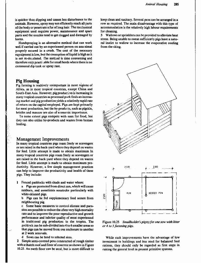
Animal Housing 285
is quicker than dipping and causes less disturbance to the animals. However, spray may not efficiently reach all parts of the body or penetrate a fur of long hair. The mechanical equipment used requires power, maintenance and spare parts and the nozzles tend to get clogged and damaged by horns.
Handspraying is an alternative method that can work well if carried out by an experienced person on ana nimal properly secured in a crush. The cost of the necessary eqyuipment is low, but the consuption of liquid is high as it is not recirculated. The method is time consuming and therefore only practi ;able for small herds where there is no communal dip tank or spray race.
Pig Housing Pig farming is realtively unimportant in most regions of Africa, as in most tropical countries, except China and South-East Asia. However, pig production is increasing in many tropical countries as processed pork finds an increas- ing market and pig production yields a relatively rapid rate of return on the capital empioyed. Pigs are kept primarily for meat production, but the by-products, such as pigskin, bristles and manure are also of economic importance.
To some extent pigs compete with man for food, but they can also utilise by-products and wastes from human feeding.
Management Improvements In many tropical countries pigs roam freely as scavengers or are raised in the back-yard where they depend on wastes for feed. Little attempt is made to obtain maximum In many tropical countries pigs roam freely as scavengers or are raised in the back-yard where they depend on wastes for feed. Little attempt is made to obtain maximum pro- ductivity. However, a few simple management practices can help to improve the productivity and health of these pigs. They include:
1 Fenced paddocks with shade and water where: a Pigs are protected from direct sun, which will cause sunburn, and sometimes sunstroke particularly with white-skinned pigs. b Pigs can be fed supplementary feed secure from neighbouring pig. c Some basic measures to control disease and para- sites are possible to reduce the often very high mortality rate and to improve the poor reproductive and growth performance and inferior quality of meat experienced in traditional pig production in the tropics. The paddock can be suMivided into 4 to 6 smaller areas so that pigs can be moved from one enclosure to another at 2 week intervals. d Sows can be bred to selected sires.
2 Simple semi-covered pens constructed of rough timber with a thatch roof and floor of concrete as shown in Figure 10.25. An earth floor can be used, but is more difficult to
keep clean and sanitary. Several pens can be arranged in a row as required. Tbe main disadvantage with this type of accommodation is the relatively high labour requirements for cleaning. 3 Wallows or sprinklers can be provided to alleviate heat stress. Being unable to sweat sufficiently pigs have a natu- ral instict to wallow to increase the evaporative cooling from the sking.
Figure 10.25 Smallholder 3 pigsty for one sow with litter
or 4 to 5 fattening pigs.
While such improvements have the advantage of low investment in buildings and less need for balanced feed rations, they should only be regarded as first steps in raising the general level in present primitive systems.

286
The raising of pigs in confinement is gradually replacing the old methods because of lower production costs, improved feed efficiency and better control of disease and parasites. Thus, the confinement system is usually advisa- ble in circumstances where:
l good management is available; l highquality pigs are introduced; l farrowings occur at regular intervals throughout the year; l land is scarce or not accessible all the year; a balanced rations are available; l labour is expe:?sive; 0 Farasiti- and disease control is necessary; o the target is commercial production; 0 herd size is reasonably large.
Some systems keep only part of the herd in confinement. The order of priority for confinement housing for the different classes of animals is usually as follows:
I Growing/finishing pigs (25~90kg or more liveweight) for higher control daily gain, better feed conversiona dna pasite control. 2 Farrowing and lactating sows, to reduce pre-weaning mortality and for higher quality weaners. 3 Gestating sows, to allow individual feeding and better control of stock.
Management Systems in Intensive Commercial Pig Production There is no standard type or system of housing for pigs. Instead, accommodation and equipment are choosen to
suit the type of management system adopted. However, there are certain similar principles and practices in most systems. These originate from the fact that most pig units will contain pigs of different ages and classes as show in Figure 10.26.
F~pl rowing-hckling Pens In small and medium scale intensive pig production units a combined fat-rowing, suckling and rearing pen is normally used. The sow is brought to this pen one week before farrowing and stays there together with her litter for 5 to 8 weeks when the piglets are weaned by removing the sow. The sow is often confined in a fat-rowing crate a few days before, and up to a week after birth to reduce piglet mortal- ity caused by overlaying or trampling. Systems I and II in Figure 10.27.
Early weaning after a suckling period of 5 to 6 weeks or even less can only be recommended where management and housing is of good standard.
The piglets remain in the farrowing pen after weaning and until they are 12 to 14 weeks of age or weigh 25 to 30kg.
Group keeping of farrowing-suckling sows that have given birth within a 2 to 3 week interval is possible, but is unusual in intensive production. However, there are few acceptance problems and the litters cross-suckle and mix freely. The pen should have at least 6m2 deep litter bedding per sow, with an additional creep area of lm2.
In a large scale unit, which has a separate farrowing house, sometimes either of the following two alternative systems are practiced instead of the system described above:
The first alternative (System III in Figure 10.27) is sim- ilar to the system already described, but the piglets are
Fur c hased boars
Culled boars
Figure 10.26 Flow Chart of rhe life cycle or pigs.

Animal HousMg 287
moved two weeks after weaning to a weaner pen where they may remain either until they are 12 to 14 weeks of age (25 to 30kg) or until 18 to 20 weeks of age (45 to 55kg). Note that the piglets should always remain in the farrov+ing/ suckling pen for a further 1 to 2 weeks after the ww has been removed so that they are not subjected to a.ly new environmental or disease stress at the same time as the;/ are weaned. The weaning pens can contain one litter or ‘.tp to 30 to 40 pigs. The pigs are often fed ‘ad libitum’.
In the second alternative showing (System IV in Figure 10.27) the sow is placed in a farrowing crate in a small pen one week prior to birth. Two weeks after fat-rowing the sow and the litter are moved to a larger suckling pen. The piglets may remain in this pen until 12 to i-4 weeks of age or be transferred to weaner accommodation two weeks after weaning.
Dry Sow Pens After weaning a sow will normally come on heat within 5 to 7 days and then at 3 week intervals until successful mating. The average weaning to conception interval can vary between 8-20 days depending on management. In the period until pregnancy has been ascertained the sow is best kept in a pen or stall in close proximity to the boar pen.
Gestating sows are kept in yards or pens in groups of up to 10 to 12 sows, that will farrow within a 2 to 3 week interval. They can also be kept in individual pens conlined in stalls 0~ tethered in stalls.
Weaner and Fattening Pens The weaners, whether they come from a farrowing pen or a weaner pen, will at 12 to 14 weeks of age be sufficiently hardened to go to a growing/finishing pen. Finishing can be accomplished either in one stage in a growing/ finishing pen from 25kg to 90kg - systems I and IV in Figure i0.27 or in two stages so that the pigs are kept iit a smz!ler growing pzn until they weigh 50 to 60kg and are then moved to a larger finishing pen where they remain until they reach marketable weight. Sye::m II in Figure 10.27. In loge scale production the pigs are arranged into groups of equal size and sex when moved into the growing/finishing pen. Although finishing pigs are sometimes kept in groups of 30 or more, pigs m a group of 9 to 12, or even les,s, show better growth performance in intensive systems. An alternative. where growing and finishing are carried out in the same facility, is to start about 12 pigs in the pen and later, during the finishing period, reduce the number to 9 by taking out the biggest or smallest pigs from each pen.
A - Combined fat-roving suckling pen (A. - after the crate has been opened or removed); B - specialised farrowing pen; C - suckling pen; D - gestation accommodation; E - pen for weaners F - growing/ finishing pen
.Figun 10.27 Flow chart of four difserent management systems in the pig production.

Replacement Pens 3 Determine the number of servicing/gestating pens. In intensive systems a sow will, on average, produce 3 to 6 litters before she is culled because of infertility, !ow produc- tivity or age. Young breeding stock should be separated from the rest of the litter at about 3 months of age, since they should be less intensively fed than the fatter&g pigs. Gilts are first covered when they are 7 to 9 months of age or weight 105 to 120kg. After mating they can either be kept in the same pen up to 1 week before far-rowing, or kept in the gestating sow accommodation, but in a separate group.
Average weaning to conception interval 20 days Gestation period less 7 days in farrowing pen 107 days Cleaning and sanitation of pen 7 days
Occupancy per cycle 134 days
Thus one place in the servicing/gestation accommoda- tion can be used for:
Boars in the tropics are usually quiet if run with other boars or with pregnant sows, but may develop vicious habits if shut up alone.
3651134 = 2.7 farrowings per year.
With a total of 27 farrowings a year
Determining the Number of Pens and Stalls Required in a Pig Unit One objective in planning a pig unit is to balance the accommodation between the various ages and numbers of pigs. Ideally, each pen should be fully occupied at all times, allowing only for a cleaning and sanitation period of about 7 days between successive groups.
In the following example the number of different pens required in a 1Csow herd, where 8 week weaning is prac- tised, will be determined.
1 Determine the fart-owing interval and number of far- rowings per year.
Average weaning to conception interval 20 days Gestation 114 days Suckling period (7 x 8 weeks) 56 days
Farro wing in tervai 190 days
Number of farrowings per sow and year z = 1.9
2 Determine the number of farrowing pens. The piglets remain in the farrowing pen until I2 weeks of
age.
Before farrowing Suckling period Rearing of weaners Cleaning and sanitation of pen
Occupation per cycle
7 days 56 days 28 days
7 days
98 days
Thus one farrowing pen can be used for:
365 3s = 3.7 farrowings per year.
A 14 sow herd with an average of 1.9 farrowings per sow
and year requires 14 x 1.9 3.7
= 7 farrowing pens.
27/2.7 = 10 places would be required.
4 Determine the number of places for replacement stock.
Presume the sows on average get 5 litters, then 20 per- cent of all litters will be from gilts.
Rearing of breeding stock (12 to 35 weeks) Gestation less 7 days in farrowing pen Cleaning and sanitation of pen
Occupancy per cycle
168 days 107 days
7 days
282 days
About 30% more animals are separated than the required number of gilts thus the required number of places in the 14 sow herd will be
14 x 1.9 x 0.2 x 1.3 x 282 = 365 6 places
5 Determine the number of places in the growinglfinish- ing accommodation:
l One stage finishing: Fattening of pigs 12 to 27 weeks of age,
(25~90kg) Extra period for last pig in the pen to
reach marketable weight Cleaning and sanitation of pen
Occupancy per cycle
105 days
21 days 7 days
133 days
Assuming that 8 pigs per litter will survive to 12 weeks of age the number of places required in the finishing accom- modation will be:
14 x 1.9 x3;;& = ,8
i-hat is 8 pens with 10 pigs in each or 10 pens ifeach litter should be kept together.
l Two stage growing/finishing unit: Growing pigs 12 to 20 weeks of age will occupy a grow-
ing pen for 63 days including 7 days for cleaning.
14 x 1.9 x 8 x 63 365
= 37 places is required in the unit.

Animal Housing 289
Finishing pigs 20 to 27 weeks of age will occupy a finishing pen for 70 days including 14 days emptying period and 7 days for cleaning. (The cmpyting period will be shorter if the pigs are sorted for size while being transferred from the growing to the finishing pens.
14 x 1.9 x 8 x 70 365
= 41 places is required in the unit
From the above example it will be appreciated that the number of pens of various kinds required in a pig unit is based on a number of factors. It is, therefore, not possible to lay down hard and fast rules about the relative number of pens and stalls. However, aguide line to the requirement of pens in herds with average or good management and performance in tropicai conditions is given in Appendix Vl.
Space Requirement In intensive pig production systems all pigs should be raised on concrete floors to provide for a clean and sanitary environment. In semi-intensive systems a concrete floor is only used in the pens for finishing pigs and perhaps in the furrowing pens, whereas an earth floor or deep litter bed- ding is used in other pens and yards. Litter may or may not be used on a concrete floor, but its use is desirable, particu- larly in farrowing pens.
Because of the cost of a concrete floor there is a tendency to reduce the floor area aIlowed per animal. However, too high stocking densities will contribute to retarding perfor- mance, increasing mortality, health and fertility problems and a high frequency of abnormal behaviour thus endan- gering the welfare of the animals. Increasing the stocking density must be accompanied by an increased standard of management and efficiency of ventilation and cooling. In particular, to aid in cooling, finishing pigs kept in a warm tropical climate should be allowed more space in their resting area than is normally recommended for pigs in temperate climates. Table 10.9 lists the recommended space allowance per animal at various stocking densities. The figures listed for high stocking density should only be used in design of pig units in cool areas and where the management level is expected to bt: above average.
The dimensions of a pen for fattening pigs are largely given by the minimum trough length required per pig at the end of their stay in the pen. See Table 10. IO. However, the width of a pen with low stocking density can be larger than the required trough length. Thii will reduce the depth to 2.0 to 2.4m, and thus the risk of having the pigs create a manure are within the pen.
Furthermore, the flexibility in the use of the pen will increase and the extra trough space allow additional anim- als to be accommodated temporarily or when the level of management improves.
Sometimes finishing pens are deliberately over-stocked. The motive for this is that all pigs in the pen will not reach marketable weight at the same time and the space left by
those pigs sent for slaughter can be utilized by the remainder. Such over-stocking should only be practised in very well managed finishing units.
General Requirements for Pig Housing A good location for a pig unit meets the following require- ments: easy access to a good ah-weather road; well-drained ground; and sufficient distance from residential areas to avoid creating a nuisance from odour and flies.
An east-west orientation is usually preferable to minim- ize exposure to the sun. Breezes across the building in summer weather are highly desirable. A prevailing wind during hot weather can sometimes justify a slight deviation from the east-west orientation. Ground cover, such as bushes and grass, can reduce reflected heat considerably, and the building should be located where it can most benefit from surrounding vegetation.
A fairly light well drained soil is preferable, and usually the highest part of the site should be selected for construction.
Pig houses should be simple, open sided structures as maximum ventilation is needed. A building for open con- finement is therefore essentially a roof carried on poles. The roof s::pporting poles are placed in the comers of the pens where they will cause least inconvenience. A free span trussed roof design would be an advantage but is more expensive.
In some circumstances it may be preferable to have solid gable ends and one tight side to give protection from wind or low temperatures, at least for part of the year. If such walls are needed they can often be temporary and be removed during hot weather to allow maximum ventila- tion. Permanent wails must be provided with large open- ings to ensure sufficient air circulation in hot weather. If there is not sufficient wind to create a draught in hot weather, ceiling fans can considerably improve the environment.
The main purpose of the building is to provide shade, and therefore the radiant heat from the sun should be reduced as much as possible. In climates where a clear sky predominates, a high building of 3m, or more: under the eaves gives moire efficient shade than a low building. A wide roof overhang is necessary to ensure shade and to protect the animals from rain. A shaded ventilation open- ing along the ridge will provide an escape for the hot air accumulating under the-roof. If made from a hard material the roof can be painted white to reduce the intensity of solar radiation. Some materials such as aIuminium reflect heat well as long as they are not too oxidized. A layer of thatch (ktr attached by wire netting beneath a galvanised steel roof will improve the micro-climate in the pens. A roof of thatch is excellent in hot climates, particularly in non-confined systems, but cannot always be used because of fire hazard and because it is attractive to birds and rodents. A pig house with two rows of pens and a central feeding alley would require a ridge height of 5 to 6 metres if covered with thatch.

290
Table 10.9 Dimensions and Area of Various Types of Pig Pens
units
Low
Stocking density
Medium High
A. Fat-rowing/ suckling pen. Resting area, if weaner pens are not used Resting area, if weaner pens are used Manure alley width Farrowing pen (System IV) Farrowing crate, length excl. trough
width depending on ?ize of sow free space behind the crate
Piglet creep (incl. in resting area)
B. Boar pen 1. Pen with yard
Resting are (shaded) Yard area (paved)
2. Pen without yard
C. Gestating sow pens I. Loose in groups of 5 - 10 sows
Resting area (shaded) Yard area (paved) Feeding stalls, depth x width
2. Individual stalls with access to manure alley. length of stalls excl. trough width of stalls width of manure alley
3. Confined in individual stalls length x width of stalls
D. Weaner pen (to 25kg or 12 wks) Resting area excluding trough Manure alley width
E. Growing pen (to 40kg or 17 wks) Resting are excluding trough Manure alley width
F. Finishing pen, resting area excl. trough For porkers to 60kg or 21 wks For beaconers to 9Qkg or 27 wks For heavy hog to 120kg or 33 wks Manure alley width
m2 m2 m rnz m m
2
m2 6 5 4.5 m2 12 10 08 m2 9 8 7
m2 2.0 1.5 1.1 m2 3.5 3.0 2.5 m 2.0 x 0.6 1.8 x 0.55 1.7 x 0.5
m 2.2 2.1 2.0 m 0.65 - 0.75 0.60 - 0.70 0.55 - 0.65 m 1.5 1.4 1.3
m 2.2 x 0.70 2.1 x 0.65 2.0 x 0.60
m2/ pig 0.35 0.30 0.25 m 1.0 1.0 1.0
m2/ pig m
m2/ pig 0.70 0.60 m2,1 pig 0.90 0.75 m?/ pig 1.0 0.85
m 1.2 - 1.4 1.2 - 1.3
10.0 8.0 1.7 -
2.0 0.65 - 0.75
0.4 2.0
0.5 1.1
7.5 6.0 6.0 5.0 1.5 1.3 4.5 4.0 2.0 2.0
0.6 - 0.7 0.55 - 0.65 0.35 0.3 1.5 1.0
0.45 1.1
0.40 1.1
0.50 0.60 0.70 1.2
The pen partitions and the I metre wall surrounding the building, which serves to reduce heat reflected from the surrounding ground, can be made of concrete blocks or burnt clay bricks for durability or perhaps soil-cement blocks, plastered for ease of cleaning. Regular white wash- ing may improve the sanitary conditions in the pens.
Doors have to be tight fitting and any other openings in the lower part of the wall surrounding the building should he avoided to exclude rats. Apart from stealing feed and spreading disease, large rats can kill piglets.
For all types of confinement housing a properly con- structed easily cleaned concrete floor is required. Eighty to 1OOmm of concrete on a consolidated gravel base is suffi-
cient to provide a good floor. A stiff mix of 1:2:4 or 1:3:5 concrete finished with a WL,~ float will give a durable non-slip floor. The pen floors should slope 2 to 3% toward the manure alley and the floor in the manure alley 3 to 5% towards the drains.
Housing for a Small Scale Pig Unit For units with 2 to 15 sows, specialized buildings for the various stages of production may not be practical or desir- able. For the smallest units of 2 to 6 sows a kind of

Animal Housing 291
universal pen which is about 2.7m wide and 2.8-3.0m deep (including feed throughj which can be used for:
! sow and her litter, or 2 litter of weaned piglets, or 3 to 4 gestating sows, or 9 growing/finishing pigs of up to 90kg live weighl, or 1 boar
This type of pen shown in Figure 10.28, provides a high degree of flexibility but usually does not allow as efficient a use of the building space as the more specialised pens.
When used for farrowing, the pen should be adapted with guard rails 25cm above floor level and 25 from the wall to protect the piglets from being crushed as shown in Figure 10.28b. However, confinement farrowing is one of the most efficient ways of reducing piglet losses. An arran- gement with fixed or removable rails, which divide the pen, as shown in Figure 10.28~ will offer some degree of confinement.
In some climates it may be desirable to give sows with litter access !o exerc:ise yards. However, for the relatively short suckling period (6 to 8 weeks), it is usually considered best to keep the sows confined in pens with their litters.
A creep for the piglets is arranged iti one corner of the pen. It is recommended that a :emporary ceiling (e.g. wire netting covered with straw) 50 to 64km above the floor in the creep area be constructed to prevent draughts and to keep warmer temperatures for the piglets during their first weeks of life. Where electricity is available, heating with an infra-red lamp may be used instead. Piglets are fed in the creep area out of reach of the sow.
Figure 10.29 shows a single row pig unit for 2 sows and fattening pigs, and Figure 10.30 a double row pig unit for 4 sows having a central feeding alley. The semi-covered
TROUGH I -- -.-
:----- --- MANURE
ALLEY \
manure alleys are arranged along the outside walls separ- ated from the resting area of the pen. This arrangement will allow rain water to help flush away the waste to the drain channel and on to the manure store which h?!p to have extra capacity for this water. However, in the 4 sow unit the farrowing pens have fully covered manure alleys for increased protection ot &he piglets.
The roof may be equipped with gutters so that rain water can be drained away separately or be collected for use as drinking water for the pigs.
A single tubular steel or round timber rail 2Ocm above the outside, rear wall (lm high) is desirable to increase security without interfering with ventilation.
Both buildings shown in Figures 10.29 and 10.30 can be extended to accommodate 2 to 4 more sows by adding 2 pens for fattening pigs at one end every time a farrowing pen is added at the other end.
Table 10.10 Minimum Trough Lengrh and Height of Partitions in Various Qpes of Pig Pens
Minimum trough Minimum height of pen
length partitions
mink m
Sow in farrowing pen
Loose dry sows in pens
Stall for dry sows
Boars
Piglets IOkg
Piglets ISkg
Pigs 2Skg
Pigs 4W Pigs fQkg Pigs 9W Pigs 12Okg
0.7
0.5
0.5
0.6
0.14-0.15
0.16-0.17
0.18 - 0.20
0.22 - 0.24
0.25 - 0.27
0.30 - 0.32
0.35 - 0.37
1.0
1.0
1.0
1.2
iIt!:
0:s
;99 0:9 1.0
2700
--~---f- -t
2700
+-
MANURE \
ALLEY \
a Universal equippedfor fartening pigs. b Universal pen equipped for furrowing/suckling (non-confined sow). c Unviersal pen equipped for farrowinglsuckling (slightly cnnjined sow).
Figure IO.28 Universal pen.
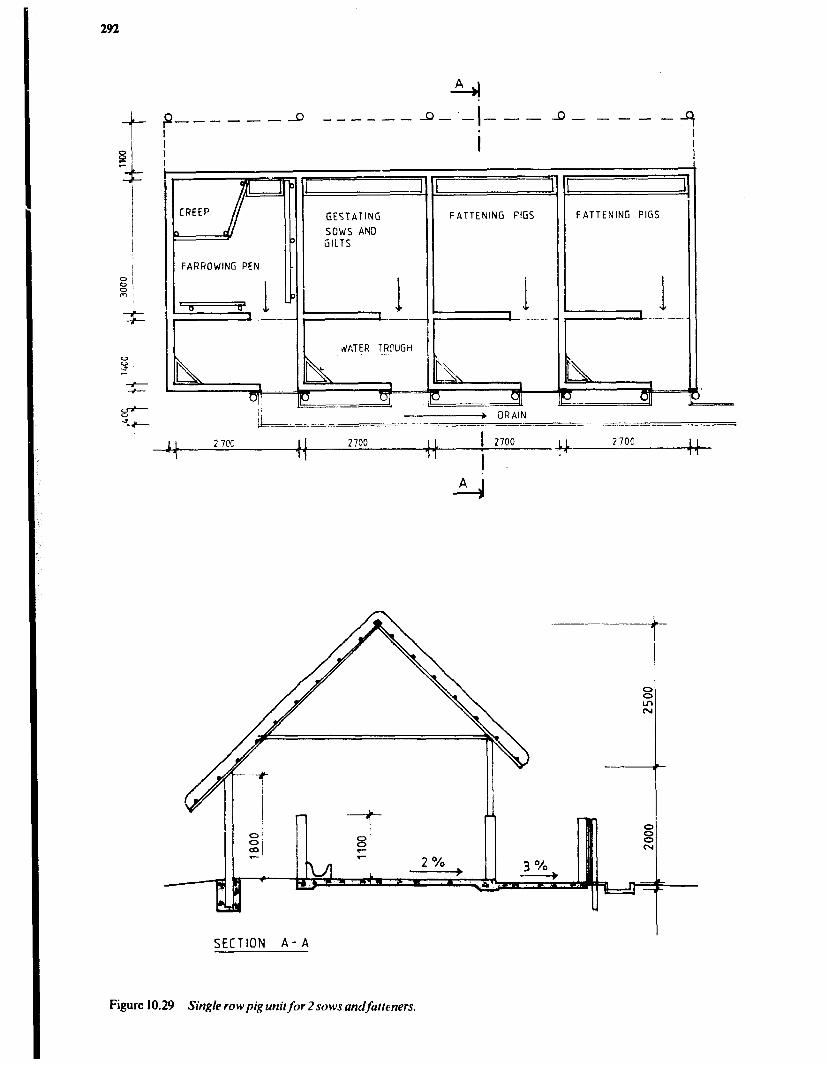
292
--I --- 9 ------ 4-.&--a-----.
i
FARROWING PEN
GESTATING FATTENING FiGS
SOWS AND
dATER TROUGH .
FATTENING PIGS
11 2 7cc II 2700 IL ! 2700 IL 27o!l 11 11 11
I. ‘,- 11
4 A'
SECTION A- A
Figure 10.29 Single row pig unit for 2 sows andfamners.

Animal Housing 293
SECTION A-A
r .-.-.-.-. -I-
I i i i I i i /
i i i i i 1 I i i i i
MEDICINE CABINET
I
\
FATTENING PENS
I I ,. 1 I
1 f 1
I j ! I i !
:: i
i i i
/
i
GESTATING SOWS FATTENING PEN
L _-._. -.-.-.-.- -.-. 1
-.-
-%I
Figure 10.30 Double row pig unit for 4 sows andfatleners.

294
Housing for the Medium.Scale Pig Unit In pig units for more than six to eight sows it becomes feasible to construct specialised pens for the various pro- duction stages, but these can still be accommodated under the same roof. A larger production volume can be accom- modated by extending the unit shown iu Figure 10.3 1 up to about 15 sows. A further inceease should then be accomp- lished by building an additional separate unit of this type with up to 15 sows, as too many animals in one building is a potential health hazard.
Housing for the Large Scale Pig Unit In large scale units special provisions must be made for efficient health control. This means: not too many animals in one building; animals of approximately the same age housed together; using an all-in-all-out system with tho- rough cleaning and disinfection of every house between each batch of pigs; placing the buildings 15 to 20m apart and surrounding the entire site with a secure fence.
Specialised pens in separate houses for the various stages ir the production is normally feasible in units for more
than 20 to 30 sows. Each type of pen can be designed with dimensions for the most efficient use of the building space, as they don’t have to tit in a layout with other types.
Farrowing House The type of farrowing pen shown in Figure 10.32 offers a relatively high degree of confinement in that the sow is restrained in a farrowing crate during farrowing. Five to ten days after farrowing the crate is removed or opened, to free the sow, as indicated in the figure. A slightly askew arrangement of the farrowing crate will allow for a longer trough for the piglets. in the front of the pen, but is more complicated to construct.
A reduction in space requirement can be accomplished by putting the sow in a farrowing pen, consisting merely of a farrowing crate with 0.5 and l.Om wide creep areas on either side, one week prior to farrowing. Two weeks after farrowing the sow and piglets must be transferred to a suckling pen equipped like the pen shown in Figure 10.28b but with the dimensions 2.3m wide, by 2.35m deep and with a 1.4m wide manure alley.
Figure 10.3 1 Pig unit for 10 sows andfatteners.

Animal Housing 295
Figure 10.32 Fat-rowing pens with crates for confinement of the sow during birth.
Housing for Growing/Finishing Pigs Growing/Finishing pens 2.8m wide by 1.9 to 2.2m deep and with a 1.2m manure alley can accommodate the fol- lowing number of pigs, according to their weight:
upto4Okg - 12pigs 40-9Okg - 9 pigs over 90kg - 7 pigs
Where it is very hot it is preferable to reduce the number of pigs per pen below the numbers given here. The manure alley must be well drained, preferably by a covered drain, but an open drain will also serve provided that it is outside of the pen to prevent urine from flowing from one pen to another. Bedding in the pens is preferable for the animals’ comfort and to reduce stress, as the bedding will provide them with something to do. Controlled feeding is impor- tant to ensure the best possible feed conversion.
Housing for Gestating Sows Gestating sows are usually the last group in a pig herd to be
considered for confinement housing. However, there are obvious advantages which could have a great influence on the production efficiency when sows are confined and controlled during gestation.
As their litters are weaned, sows can be returned to the gestating sow structure and placed in one of the pens arranged on either side of the ; boar pens for easy manage- ment of sows in heat. After mating and the three week control period, the sows should be re-grouped according to the actual farrowing dates.
The type of accommodation shown in Figure 10.33a will always have four sows per group as the gates in the manure alley are used to enclose the sows in their stalls while cleaning the pen, The stalls, which are used for both feeding and resting, should be 0.60 to 0.75m wide, depending on size of the sows.
With the type shown in Figure 10.33b, the numbers in the groups can vary according to the size of the herd and farrowing pattern, but sows in one group should be in about the same far-rowing period (within about 10 to 15 days of each other).
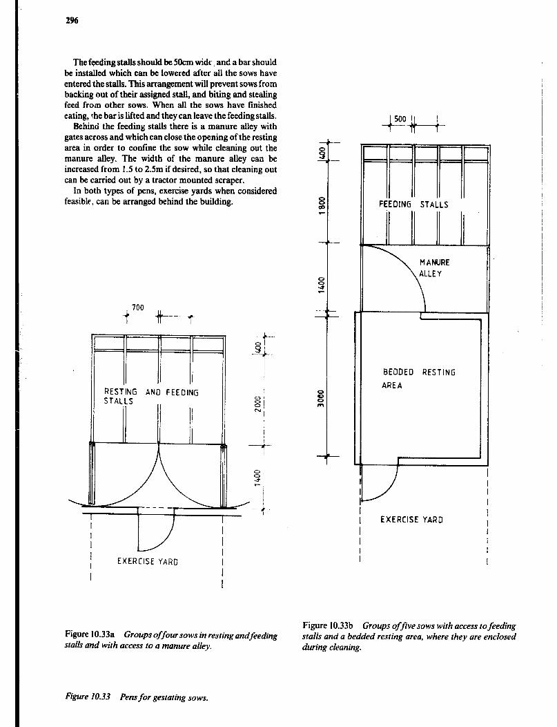
2%
The feeding stalls should be 5Ocm widr, and a bar should be installed which can be lowered after all the sows have entered the stalls. This arrangement will prevent sows from backing out of their assigned stall, and biting and stealing feed from other sows. When all the sows have finished eating, rhe bar is lifted and they can leave the feeding stalls.
Behind the feeding stalls there is a manure alley with gates across and which can close the opening of the resting area in order to confine the sow while cleaning out the manure alley. The width of the manure alley can be increased from 1.5 to 2.5m if desired, so that cleaning out can be carried out by a tractor mounted scraper.
In both types of pens, exercise yards when considered feasiblr, can be arranged behind the building.
-
I
f EXERCISE YARD
I I
-
-
-
- -
-
FEEDING STALLS
w MANURE
\
ALLEY
BEDDED RESTING
AREA
EXERCISE YARD
Figure 10.33a Groups offour sows in resting andfeeding stalk and with access to a manure alley.
Figure 10.33b Groups ofjive sows with access to feeding stalls and a bedded resting area, where they are enclosed during cleaning.
Figure 10.33 Pens for gestating sows.
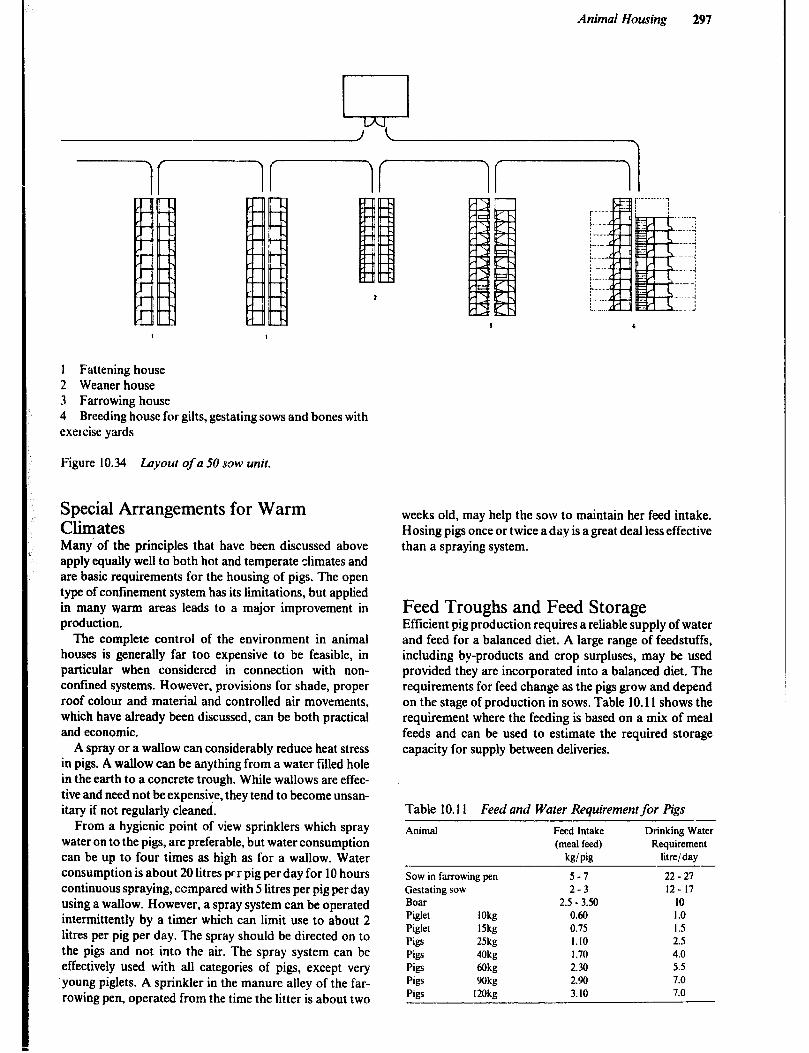
Animal Housing 291
. .
*
1 Fattening house 2 Weaner house 3 Farrowing house 4 Breeding house for gilts, gestating sows and bones with exercise yards
Figure 10.34 layout of a 50 sow unit.
Special Arrangements for Warm Climates Many of the principles that have been discussed above apply equally well to both hot and temperate climates and are basic requirements for the housing of pigs. The open type of confinement system has its limitations, but applied in many warm areas leads to a major improvement in production.
The complete control of the environment in animal houses is generally far too expensive to be feasible, in particular when considered in connection with non- confined systems. However, provisions for shade, proper roof colour and material and controlled air movements, which have already been discussed, can be both practical and economic.
A spray or a wallow can considerably reduce heat stress in pigs. A wallow can be anything from a water filled hole in the earth to a concrete trough. While wallows are effec- tive and need not be expensive, they tend to become unsan- itary if not regularly cleaned.
From a hygienic point of view sprinklers which spray water on to the pigs, are preferable, but water consumption can be up to four times as high as for a wallow. Water consumption is about 20 litres pr r pig per day for 10 hours continuous spraying, compared with 5 litres per pig per day using a wallow. However, a spray system can be operated intermittently by a timer which can limit use to about 2 litres per pig per day. The spray should be directed on to the pigs and not into the air. The spray system can be effectively used with all categories of pigs, except very ‘young piglets. A sprinkler in the manure alley of the far- rowing pen, operated from the time the litter is about two
weeks old, may help the sow to maintain her feed intake. Hosing pigs once or twice a day is a great deal less effective than a spraying system.
Feed Troughs and Feed Storage Efficient pig production requires a reliable supply of water and feed for a balanced diet. A large range of feedstuffs, including by-products and crop surpluses, may be used provided they are incorporated into a balanced diet. The requirements for feed change as the pigs grow and depend on the stage of production in sows. Table 10.11 shows the requirement where the feeding is based on a mix of meal feeds and can be used to estimate the required storage capacity for supply between deliveries.
Table 10.11 Feed and Water Requirement for Pigs
Animal Feed Intake (meal feed)
kg! pig
Drinking Water Requirement
lit=/ day
Sow in farrowing pen 5-7 Gestating sow 2-3 Boar 2.5 - 3.50 Piglet IOkg 0.60 Piglet 15kg 0.75 Pigs 25kg I.10 Pigs 40kg 1.70 Pigs akg 2.30 Pigs Wk 2.90 Pigs I2Okg 3. IO
22 - 21 IZ- 17
IO 1.0 1.5 2.5 4.0 5.5 7.0 7.0
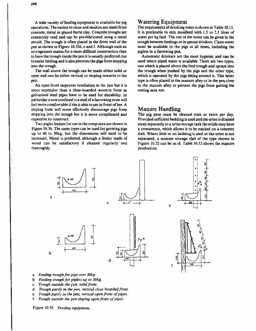
A wide variety of feeding equipment is available for pig operations, The easiest to clean and sanitize are made from concrete, metal or glazed burnt clay. Concrete troughs are commonly used and can be pre-fabricated using a metal mould. The trough is often placed in the front wall of the pen as shown in Figure 10.35d, e and f. Although such an arrrngement makes for a more difficult construction than to have the trough inside the pen it is usually preferred due to easier feeding and it also prevents the pigs from stepping into the trough.
The wall above the trough can be made either solid or open and can be either vertical or sloping inwards to the pen.
An open front improves ventilation in tht pen but it is more expensive than a close-boarded woo&n front as galvanised steel pipes have to be used for durability. In particular a sow confined in a stall of a farrowing crate will feel more comfortable if she is able to see in front of her. A sloping front will more effectively discourage pigs from stepping into the trough but it is more complicated and expensive to construct.
Two piglet feeders for use in the creep area are shown in Figure 10.36. The same types can be used for growing pigs up to 40 to 50kg, but the dimensions will need to be increased. Metal is preferred, although a feeder made of wood can be satisfactory if cleaned regularly and thoroughly.
4 LOO 1
1
a
Watering Equipment The requirement of drinking water is shown in Table 10.11. It is preferable to mix mealfeed with 1.5 to 2.1 litres of water per kg feed. The rest of the water can be given in the trough between feedings or in special drinkers. Clean water must be available to the pigs at all times, including the piglets in a far-rowing pen.
Automatic drinkers are the most hygienic and can be used where piped water is available. There are two types, one which is placed above the feed trough and sprays into the trough when pushed by the pigs and the other type, which is operated by the pigs biting around it. This latter type is often placed in the manure alley or in the pen close to the manure alley to prevent the pigs from getting the resting area wet.
Manure Handling The pig pens must be cleaned once or twice per day. Provided sufticient bedding is used and the urine is drained away separately to a urine storage tank the solids may have a consistency, which allows it to be stacked on a concrete slab. Where little or no bedding is used or the urine is not separated, a manure storage slab of the type shown in Figure 10.22 can be used. Table 10.12 shows the manure production.
d
a Feeding trough for pigs over 30kg. b Feeding trough for piglets up to 30kg. c Trough outside the pen, solidfront. d Trough partly in the pen, vertical close boarded front. e Trough partly in the pen, vertical open front of pipes. f Trough outside the pen sloping open front of pipes.
Figure 10.35 Feeding equipment.
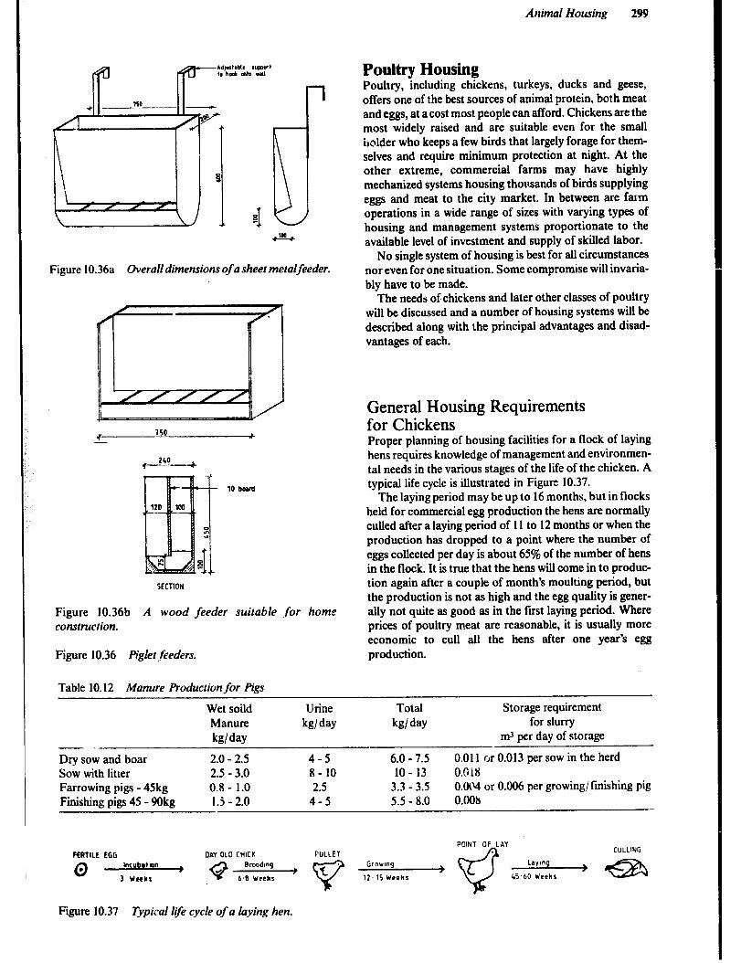
Animal Housing 299
1
Figure 10.36a OveraN dimensions of a sheet metalfeeder.
SECTION
Figure 10.36b A wood feeder suitable *for home construction.
Figure 10.36 Piglet feeders.
Table 10.12 Manure Production for Pigs
Poultry Housing Poultry, including chickens, turkeys, ducks and geese, offers one of the best sources of animal protein, both meat and eggs, at a cost most people can afford. Chickens are the most widely raised and are suitable even for the small holder who keeps a few birds that largely forage for them- selves and require minimum protection at night. At the other extreme, commercial farms may have highly mechanized systems housing thousands of birds supplying eggs and meat to the city market. In between are farm operations in a wide range of sizes with varying types of housing and management systems proportionate to the available level of investment and supply of skilled labor.
No single system of housing is best for all circumstances nor even for one situation. Some compromise will invaria- bly have to be made.
The needs of chickens and later other classes of poultry will be discussed and a number of housing systems will be described along with the principal advantages and disad- vantages of each.
General Housing Requirements for Chickens Proper planning of housing facilities for a flock of laying hens requires knowledge of management and environmen- tal needs in the various stages of the life of the chicken. A typical life cycle is illustrated in Figure 10.37.
The laying period may be up to 16 months, but in flocks held for commercial egg production the hens are normally culled after a laying period of 11 to 12 months or when the production has dropped to a point where the number of eggs collected per day is about 65% of the number of hens in the flock. It is true that the hens will come in to produc- tion again after a couple of month’s moulting period, but the production is not as high and the egg quality is gener- ally not quite as good as in the first laying period. Where prices of poultry meat are reasonable, it is usually more economic to cull all the hens after one year’s egg production.
Wet soild Urine Total Storage requirement Manure kg/ day kg/ day for slurry b/day m-1 per day of storage
-. Dry sow and boar 2.0 - 2.5 4-5 6.0 - 7.5 0.011 or 0.013 per sow in the herd Sow with litter 2.5 - 3.0 8- 10 10 - 13 O.Oi8 Farrowing pigs - 45kg 0.8 - 1.0 2.5 3.3 - 3.5 O.Ot~ or 0.006 per growing/ finishing pig Finishing pigs 45 - 9Okg 1.5 - 2.0 4-5 5.5 - 8.0 O.OO&
POINT OF LAY
FERTILE tGG DAY 010 CHICK PULLET CULLING
IncubW~n Broodmq Grovmq LayInq >
3 WCCLI 6.8 Weeks 12-15 Weeks t.S-60 Weeks
Figure 10.37 Typical 119 cycle of a laying hen.
300
Site Sqlectian The best site is one that is welldrained, elevated but fairly level, and has an adequate supply of drinking water nearby.
Regardless of the typ or size of the housing system, the site for canstruction should be selected to provide adequate ventilation, but be protected from strong winds. An area under cultivation, producing low growing crops, will be slightly cooler than an area of bare ground. High trees can provide shade while at the same time actually increasing ground level breezes. Bushes planted at one windward comer and also at the diagonally opposite comer will induce air currents witbin the building to make existing bmise the heat from direct solar radiation.
Since all buildings used for poultry housing tend to produce odours, they should be located well downwind from nearby dwellings. If there are several poultry build- ings in a group it is desirable to have them separated 10 to 15m in order to minimize the possibility of the spread of disease.
Brooding buildings should be isolated from other poul- try buildings by 30 metrcs or more and be self-contained in respect of feed supplies and storage of equipment. If the same person cares for both layers and growing birds, a disinfectant foot bath at the entrance to the brooding area is an added precaution. All buildings should be constructed on well-drained sites where drives and paths between build- ings will not become muddy even during the rainy season.
Environmental Requirements The effects of temperature &tl: humidity on the biids make it apparent that in most areas of East and Southeast Africa the principal environmental concern is to keep the flock as cool as possible. Shade, good ventilation with natural breezes, freedom from roof radiation and the indirect :-adi- ation from bare ground are aU importam. c)Q in a few high altitude areas does protection from wind and low temperatures become a significant consideration.
Humidity seems impn%+nt in only two respects. Very low humidity causes objectionably dusty conditions and high humidity combined with temperatures above 27°C seems to interfere with the physiological cooling mecha- nism and increases the possibility of death.
Day old chicks require a temperature of 33” to 35”. This temperature is maintained for a week and is then gradually lowered to the ambient temperature by the end of 5 weeks.
In addition to providing a good environment, the hous- ing should offer protection from predators and theft as well as the exclusion of rodents and birds. These latter two not onlv carry disease, but they can consume enough feed to make a significant economic difference.
The effect of light on egg production has been discussed earlier. Additional hours of light can be achieved by instal- ling one 40W electric light bulb per 15m2 floor space in a position about 2.2m above floor level.
More important than the hours of light, however, is the maintenance of the lighting schedule, since any sudden
change in the length of the photo-period is likely to result in a significant drop in production. Fourteen hours of light throughout the laying period is optimum.
A schedule with gradually decreasing b.ours of light may be used in windowless houses for maturing pullets. This postpones laying, but results in larger eggs being produced from the start of laying.
In warm climates near the Equator, houses are open for natural ventilation, however, and the day length is close to 12 hours throughout the year. The result is that pullets start to lay at 14 to 18 weeks of age and egg size, which is small at first, gradually increases during the fmt 3 months.
Broiler houses are often lighted 24 hours per day to encourage maximum feed consumption and rate of gain.
Proper design and management of the poultry house can effectively contribute to the prevention of disease in the flock. In general it is best if the titter is dry but not too dusty. If no litter is used, the floor and wall surfaces should be designed so that they can be easily cleaned between flocks and stay reasonably clean during use.
Construction Details In most hot climates there wilI be many more days when a cooling breeze is needed rather than protection from a chilling wind. A wall construction consisting of a solid base, which protects from indirect radiation from the ground, hid an open space covered with mesh above it, is therefore preferred for all four walls in most types of chicken houses. A hessian or reed curtain that can be dropped on the windward side will offer extra protection and, if installed on the east and west, it may also protect from direct sunshine. An arrangement where the top end of the hessian is fixed to the wall plate and the bottom end attached to a gum pole around which it can be rolled when not in use, will provide for smooth operation. In high altitude areas off-cuts may be used on the gable ends, but 15 to 20mm spaces should be left between them to improve the ventilation. The width of the building should not exceed 9m for efficient cross ventilation.
Lower Wall Design up to 1OOOmm of solid walls can be ma&a nf zanrr cl.AlnhL .“““o;;iy u;;;:s* Bag -*&&ig Md give __--- . -. . . ..J .a.UUU”,b U‘aa a smooth easily cleaned finish, but adobe blocks will require the extra protection of plastering to prevent the birds from destroying the wall by pecking.
The &per Wall Design to the total height of the wall, including the solid base should be about 2m. Gum poles treated with wood preservative and set SOOnun deep in concrete are a practical means of supporting the roof and upper wall structure. Eighteen millimetre wire mesh is small enough to keep out rodents and birds. A tight fitting door is essential.
Thefloor in a poultry house may consist of gravel or well drained soil, but concrete is desirable because, it is f illy cleaned, durable and considerably more rat proof, , . tori- Crete floor should be 80 to 1OOmm thick and be made of a stiff mix, 1:2:4 or 1:3:5 concrete, placed on a firm base at least 150mm above ground level and given a smooth finish with a steel trowel.
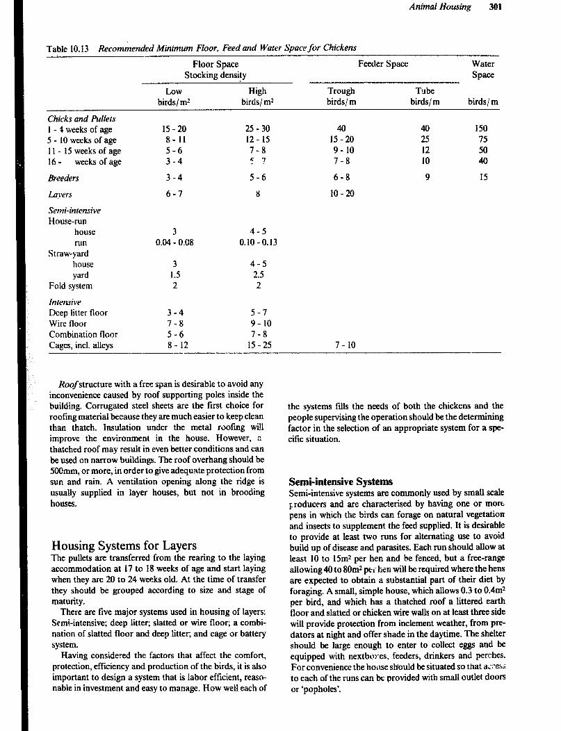
Animal Housing 301
Table 10.13 Recommended Minimum Floor, Feed and Water Space for Chickens
Floor Space Feeder Space Water Stocking density Space
Low High Trough Tube birds/ m2 birds/m* birds/m birds/m birds/m
Chicks and Pullets 1 - 4 weeks of age 5 - 10 weeks of age II- 15weeksofage 16 - weeks of age
Breeders
layers
Semi-intensive House-run
house run
Straw-yard house yard
Fold system
Intensive Deep litter floor Wire floor Combination floor Cages, incl. alleys
15-20 25 - 30 40 40 150 8- 11 12 - 15 15-20 25 75 5-6 7-8 9- 10 12 50 3-4 5 ? 7-8 10 40
3-4 5-6 6-8 9 15
6-7 8 10-20
3 4-5 0.04 - 0.08 0.10-0.13
3 4-5 1.5 2.5 2 2
3-4 5-7 7-8 9- 10 5-6 7-8 8- 12 15-25 7- 10
Roofstructure with a free span is desirable to avoid any inconvenience caused by roof supporting poles inside the building. Corrugated steel sheets are the first choice for roofing material because they are much easier to keep clean than thatch. Insulation under the metal roofing will improve the environment in the house. However, a thatched roof may result in even better conditions and can be used on narrow buildings. The roof overhang should be 5OOmm, or more, in order to give adequate protection from sun and rain. A ventilation opening along the ridge is usually supplied in layer houses, but not in brooding houses.
Housing Systems for Layers The pullets are transferred from the rearing to the laying accommodation at 17 to 18 weeks of age and start laying when they are 20 to 24 weeks old. At the time of transfer they should be grouped according to size and stage of maturity.
There are live major systems used in housing of layers: Semi-intensive; deep litter; slatted or wire floor; a combi- nation of slatted floor and deep litter, and cage or battery system.
Having considered the factors that affect the comfort, protection, efficiency and production of the birds, it is also important to design a system that is labor efficient, reaso- nable in investment and easy to manage. How well each of
the systems fills the needs of both the chickens and the people supervising the operation should be the determining factor in the selection of an appropriate system for a spe- cific situation.
Semi-intensive Systems Semi-intensive systems are commonly used by small scale producers and are characterised by having one or mort pens in which the birds can forage on natural vegetation and insects to supplement the feed supplied. It is desirable to provide at least two runs for alternating use to avoid build up of disease and parasites. Each run should allow at least IO to 15m* per hen and be fenced, but a free-range allowing 40 to 8Om* pel’ hen will be required where the hens are expected to obtain a substantial part of their diet by foraging. A small, simple house, which allows 0.3 to 0.4m2 per bird, and which has a thatched roof a littered earth floor and slatted or chicken wire walls on at least three side will provide protection from inclement weather, from pre- dators at night and offer shade in the daytime. The shelter should be large enough to enter to collect eggs and be equipped with nextbores, feeders, drinkers and perches. For convenience the honse should be situated so that a;:‘ess to each of the runs can be provided with small outlet doors or ‘popholes’.
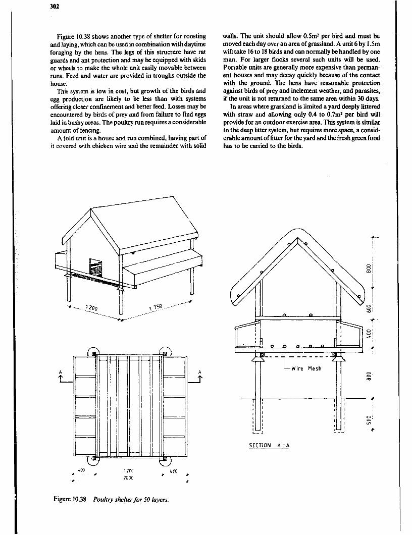
302
Figure 10.38 shows another type of shelter for roosting and laying, which can be used in combination with daytime foraging by the hens. The legs of this structure have rat guards and ant protection and may be equipped with skids or wheels to make the whole unit easily movable between runs. Feed and water are provided in troughs outside the house.
This system is low in cost, but growth of the birds and egg production are likely to be less than with systems offering closer confinement and better feed. Losses may be encountered by birds of prey and from failure to find eggs laid in bushy areas. The poultry run requires a considerable amount of fencing.
A fold unit is a house and run combined, having part of it covered with chicken wire and the remainder with solid
walls. The unit should allow 0.5m2 per bird and must be moved each day over an area of grassland. A unit 6 by 1.5m will take 16 to 18 birds and can normally be handled by one man. For larger flocks several such units will be used. Portable units are generally more expensive than perman- ent houses and may decay quickly because of the contact with the ground. The hens have reasonable protection against birds of prey and inclement weather, and parasites, if the unit is not returned to the same area within 30 days.
In areas where grassland is limited a yard deeply littered with straw aud allowing only 0.4 to 0.7mr per bird will provide for an outdoor exercise area. This system is similar to the deep litter system, but requires more space, a consid- erable amount of litter for the yard and the fresh green food has to be carried to the birds.
SECTION A -A
Figure 10.38 Poultry shelter for 50 layers.
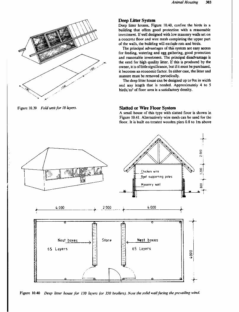
Animal Housing 303
Figure 10.39 Fold unir for 18 layers.
Deep Litter System Deep litter houses, Figure 10.40, confine the birds in a building that offers good protection with a reasonable investment. If well designed with low masonry walls set on a concrete floor and wire mesh completing the upper part of the walls, the building will exclude rats and bids.
The principal advantages of this’ system are easy access for feeding, watering and egg gathering, good protection and reasonable investment. The principal disadvantage is the need for high quality litter. If this is produced by the owner, it is of little signikance, but ifit must be purchased, it becomes an economic factor. In either case, the litter and manure must be removed periodically.
The deep litter house can be designed up to 9m in width and any length that is needed. Approximately 4 to 5 bids/ m2 of floor area is a satisfactory density.
H&ted or Wire Floor System A small house of this type with slatted floor is shown in Figure 10.41. Alternatively wire mesh can be used for the floor. It is built on treated wooden piers 0.8 to lm above
f supportmg poles
Nest boxes >
65 Layers
II II il ]I <
Nest boxes
65 Layers
Figure 10.40 Deep litter house for 130 layers (or 350 broilers). hbre the solid wallfacing the prevailing wind-
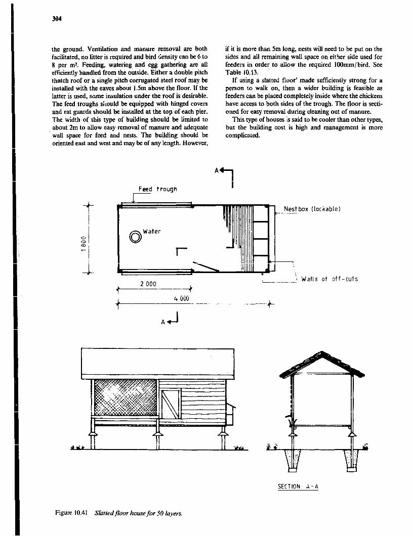
304
the ground. Ventilation and manure removal are both facilitated, no litter is required and bird density can be 6 to 8 per m2. Feeding, watering and egg gathering are all efficiently handled from the outside. Either a double pitch thatch roof or a single pitch corrugated steel roof may be installed with the eaves about 1.5m above the floor. If the latter is used, some insulation under the roof is desirable. The feed troughs shuld be equipped with hinged covers and rat guards should be in&&d at the top of each pier. The width of this type of building should be limited to about 2m to allow easy removal of manure and adequate wall space for feed and nests, The building should be oriented east and west and may be of any length. However,
Feed trough I
if it is more than 5m long, nests will need to be put on the sides and all remaining wall space on eitLr side used for feeders in order to allow the required lOOmm/bird. See Table 10.13.
If using a slatted floor’ made sufficiently strong for a person to walk on, then a wider bnilding is feasible as feeders can be placed completely inside where the chickens have access to both sides of the trough. The floor is secti- oned for easy removal during cleaning out of manure.
This type of houses is said to be cooler than other types, but the building cost is high and management is more complicated.
A
1
Nest box (lockable) t-------
1 .--.._1\ Walls ot off-cuts
SECTION A-A
Figure 10.41 Slatredfloor home for 50 layers.
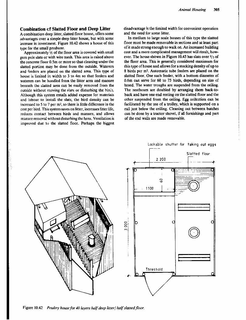
Combination cf Slatted Floor and Deep Litter A combination deep litter, slatted floor house, offers some advantages over a simple deep litter house, but with some increase in investment. Figure 10.42 shows a house of this type for the small producer.
Approximately ‘/ of the floor area is covered with small gum pole slats or with wire mesh. This area is raised above the concrete floor O.Sm or more so that cleaning under the slatted portion may be done from the outside. Waterers and feeders are placed on the slatted area. This type of house is limited in width to 3 to 4m so that feeders and waterers can be handled from the litter area and manure beneath the slatted area can be easily removed from the outside without moving the slats or disturbing the hhis. Although this system entails added expense for materiais and labour to install the slats, the bird density can be increased to 5 to 7 per rn’, so there is little difference in the cost per bird. This system saves on litter, increases litter life, reduces contact between birds and manure, and allows manure removal without disturbing the hens. Ventilation is improved due tl> the slatted floor. Perhaps the biggest
disadvantage is the limited width for convenient operation and the need for some litter.
In medium to large scale houses of this type the slatted floor must be made removable in sections and at least part of it made strong enough to walk on. An increased building cost and a more complicated management will result, how- ever. The house shown in Figure 10.43 has slats over 213 of the floor area. This is generally considered maximum for this type of house and allows for a stocking density of up to 8 birds per m2. Automatic tube feeders are placed on the slatted floor. One such feeder, with a bottom diameter of 0.6m can serve for 60 to 75 birds, depending on size of breed. The water troughs are suspended from the ceiling. The nestboxes are doubled by arranging them back-to- back and have one end resting on the slatted floor and the other suspended from the ceiling. Egg collection can be facilitated by the use of a trolley, which is supported on a rail just below the ceiling, Cleaning out between batches can be done by a tractor shovel, if all furnishings and part of the end walls are made removable.
Animal Housing 305
Lockable shutter for taking out eggs
Slatted floor
c ---..+
Figure 10.42 Poultry housefor 40 layers halfdeep litrerl haVslattedfloor.
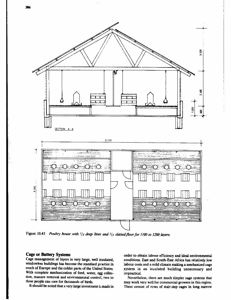
306
rr -
Figure 10.43 Poultry house with l/3 deep litter and J/J slattedfloorfor 1100 to 1200 layers.
Cage or Battery Systems Cage management of layers in very large, well insulated, windowless buildings has become the standard practice in much of Europe and the colder parts of the United States. With complete mechanization of feed, water, egg collec- tion, manure removal and environmental control, two to three people can care for thousands of bids.
It should be noted that a very large investment is made in
order to obtain labour efficiency and ideal environmental conditions. East and South-East Mrica has relatively low labour costs and a mild climate .making a mechanized cage system in an insulated building unnecessary and impractical.
Nevertheless, there are much lrimpler cage systems that may work very well for commercial growers in this region. These consist of rows of stair-step cages in long narrow
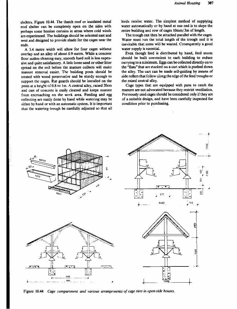
Animal Housing 301
shelters. Figure 10.44. The thatch roof or insulated metal roof shelter can be completely open on the sides with perhaps some hessian curtains in areas where cold winds are experienced. The buildings should be oriented east and west and designed to provide shade for the cages near the ends.
A 3.4 metre width will allow for four cages without overlap and an alley of about 0.9 metre. While a concrete floor makes cleaning easy, smooth hard soil is less expen- sive and quite satisfactory. A little loose sand or other litter spread on the soil before the manure collects will make manure removal easier. The building posts should be treated with wood preservative and be sturdy enough to support the cages. Rat guards should be installed on the posts at a height of 0.8 to 1 m. A central alley, raised 20cm and cast of concrete is easily cleaned and keeps manure from encroaching on the work area. Feeding and egg collecting are easily done by hand while watering may be either by hand or with an automatic system. It is important that the watering trough be carefully adjusted so that all
birds receive water. The simplest method of supplying water automatically or by hand at one end is to slope the entire building and row of cages lOmm/3m of length.
The trough can then be attached parallel with the cages. Water must run the total length of the trough and it is inevitable that some will be wasted. Consequently a good water supply is essential.
Even though feed is distributed by hand, feed stores should be built convenient to each building to reduce carrying to a minimum. Eggs can be collected directly on to the “flats” that are stacked on a cart which is pushed down the alley. The cart can be made self-guiding by means of side rollers that follow along the edge of the feed troughs or the raised central alley.
Cage types that are equipped with pans to catch the manure are not advocated because they restrict ventilation. Previously used cages should be considered only if they are of a suitable design, and have been carefully inspected for condition prior to purchasing.
Figure 10.44 Cage compartment and various arrangements of cage tiers in open-side houses.
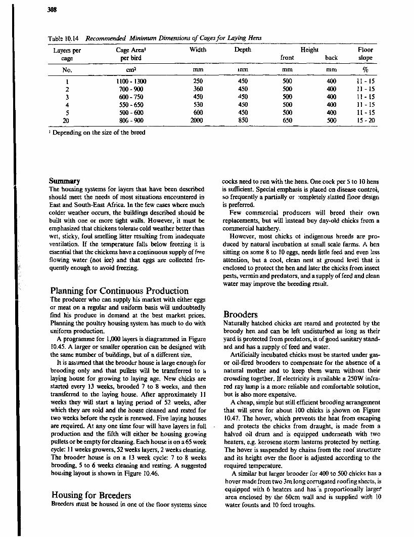
Tabl:: lg.14 Recommended Minimum Dimensions 01 Cages fir Laying Hens
Layers per Cage Area’ cage per bird
Width Depth Height Floor front back slope
No. cm2 mm mm mm mm %
1 1100 - 1300 250 450 500 400 11- 15 2 700-900 360 450 500 400 11- 15 3 600-750 450 40 500 400 II- 15 4 550 - 650 530 450 500 400 ll- 15 5 500-600 600 450 500 400 11- 15
20 8OG-900 2oQO 850 650 500 15-20
1 Depending on the size of the breed
Summary The housing systems for layers that have been described should meet the needs of most situations encountered in East and South-East Africa. In the few cases where much colder weather occurs, the buildings described should be built with one or more tight walls. However, it must be emphasized that chickens tolerate cold weather better than wet, sticky, foul smelling litter resulting from inadequate ventilation. If the temperature falls below freezing it is essential that the chickens have a continuous supply of free flowing water (not ice) and that eggs are collected fre- quently enough to avoid freezing.
Planning for Continuous Production The producer who can supply his ‘market with either eggs or meat on a regular and uniform basis will undoubtedly find his produce in demand at the best market prices. Planning the poultry housing system has much to do with uniform production.
A programme for 1,000 layers is diagmmmed in Figure 10.45. A larger or smaller operation can be designed with the same number of buildings, but of a different size.
It is assumed that the brooder house is large enough for brooding only and that pullets will be transferred to a laying house for growing to laying age. New chicks are started every 13 weeks, brooded 7 to 8 weeks, and then transferred to the laying house. After approximately 11 weeks they will start a laying period of 52 weeks, after which they are sold and the house cleaned and rested for two weeks before the cycle is renewed. Five laying houses are required. At any one time four will have layers in full production and the filth will either be housing growing pullets or be empty for cleaning. Each house is on a 65 week cycle: 11 weeks growers, 52 weeks layers, 2 weeks cleaning. The brooder house is on a 13 week cycle: 7 to 8 weeks brooding, 5 to 6 weeks cleaning and resting. A suggested housing layout is shown in Figure 10.46.
Housing for Breeders Breeders must be housed in one oi the floor systems since
cocks need to run with the hens. One cock per 5 to 10 hens is sufficient. Special emphasis is placed on disease control, so frequently a partially or :ompletely slatted floor design is preferred.
Few commercial producers will breed their own replacements, but will instead buy day-old chicks from a commercial hatchery.
However, most chicks of indigenous breeds are pro- duced by natural incubation at small scale farms. A hen sitting on some 8 to 10 eggs, needs little feed and even less attention, but a cool, clean nest at ground level that is enclosed to protect the hen and later the chicks from insect pests, vermin and predators, and a supply of feed and clean water may improve the breeding result.
Brooders Naturally hatched chicks are reared and protected by the broody hen and can be left undisturbed as long as their yard is protected from predators, is of good sanitary stand- ard and has a supply of feed and water.
ArtiCcially incubated chicks must be started under gas- or oil-tired brooders to compensate for the absence of a natural mother and to keep them warm without their crowding together. If electricity is available a 250W infra- red ray lamp is a more reliable and comfortable solution, but is also more expensive.
A cheap, simple but still efficient brooding arrangement that will serve for about 100 chicks is ?hown on Figure 10.47. The hover, which prevents the heat from escaping and protects the chicks from draught, is made from a halved oil drum and is equipped underneath with two heaters, e.g. kerosene storm lanterns protected by netting. The hover is suspended by chains from the roof structure and its height over the floor is adjusted according to the required temperature.
A similar but larger brooder ior 400 to 500 chicks has a hover made from two 3m long corrugated roofing she&s, is equipped with 6 heaters and has>a proportionally larger area enclosed by the 6Ocm wall and is supplied with 10 water founts and 10 feed troughs.
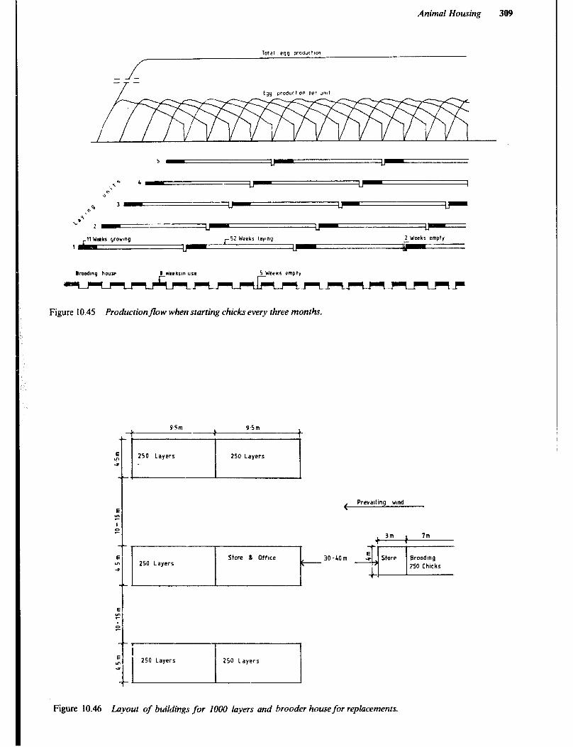
Animal Housing 309
Total egg proourtwn
1
2 Weeks empty
0 Wrckrm “se 5 Weeks wnpty
Figure 10.45 Productionflow when starting chicks every three months.
Figure 10.46 Layout of buildirzgs for 1000 layers and brooder house for replacements.

310
Cham to rmf structure I
Figure 10.47 Brooding arrangement for approximately I00 chicks.
Housing for Pullets and Broilers In the past, poultry meat has been derived chiefly from culled hyers. This is still the main source of poultry meat in most developing countries, although there is an increasing shift to rearing chickens specifically for meat. Broilers, the common term for meat birds, are fast-growing strains which reach market weight of 1.6kg in 8 to 12 \veeks. The commercial production of poultry meat is now based primarily on broilers.
In a semi-intensive system the growing pullets may obtain part of their food by scavenging for forage, seed, etc. A fenced yard allowing 5 to 8m2 per bid is preferable to open land. At least part of the yard should have shade cover and a simple building in which the birds can be enclosed at night will be required. The building should allow 0.2m2 per bid, have good ventilation, perches for roosting and offer protection against predators and incle- ment weather. The birds should be moved at regular inter- vals to a different yard in order to avoid a build-up of worm infestation.
There is little difference in the rearing of chicks to become pullet replacements for the laying flock or broilers for market. The same environmzu and housing are suita- ble, so they will be considered tk>gether.
Brooding and rearing are floor-managed operations. It is common practice to keep broilers or pullets in the same house from the time they are one day old, first on newspap ers or thinly spread litter, and later, on deep litter. When broilers are marketed at 8 to IO weeks of age, or pullets are transferred to the laying house at 16 to 18 weeks of age, the litter is removed so that the house can be thoroughly cleaned and disinfected. Therefore, the house should be designed and built to allow for easy and efficient cleaning. Pullets and broilers are not grown together because of the different length growing periods and differing schedules for artificial lighting.
Chicks are started in a brooder, which may be of the type discussed in the previous section and remain there for six to eight weeks. During this time it is desirable to conserve heat and to prevent draughts, and in this, the building design can be an important factor. A method that is widely used in the United States called “end room” brooding works well and seems adaptable to warm climates as well. By taking advantage of the fact that chicks up to 4 weeks old require only */J to r/2 as much floor space as they will need later on, one end and enough of the adjacent sides are closed in tightly to provide 0.05m2 of floor space per chick to be brooded. Off-cuts, with low thermal capacity, are ideal for enclosing the wall. A hessian curtain makes the fourth (inside) wall to complete the temporary enclosure. The baby chicks can then be confined in the space around the brooder in the enclosed end of the house. See Figure 10.48.
The balance of the walls are covered with 18 to 25mm wire mesh. At the end of the brooding period the brooder is raised to the ceiling for storage, the hessian curtain is lifted and the chicks are allowed into the balance of the house which should provide from 0,08m2/ bird for broilers to O.l7m*/ bird for pullets.
Depending on the maximum temperatures expected, it may be necessary to provide some ventilator openings in the tight walls. An adjustable gable-end ventilator is par- ticularly desirable as the roof will not have a ridge vent due to the brooding operation.
If cool, breezy weather is expected, one or more of the screened sides may be equipped with hessian curtains.
Equipment and Stores in addit;on to what has already been described, any chicken house will require equipment such as waterers, feeders and a feed store and perhaps perches for roosting. Houses for floor managed layers or breeders will require nestboxes. A store for eggs may be required in any laying house. Feeders and waterers should be in sufficient numbers for easy access (particularly important for young chicks), be long enough for each bird to have its place and have sufficient holding capacity. The Tables 10.13 and 10.15 provide some information for their design. Most chickens in intensive production are fed water and mash on a free choice basis. Note: The cumulative feed consumption in pullets from one day to the point of laying at 20 to 24 weeks is lO-12kg. The rearing of one broiler from one day old to marketable weight (2kg live weight) at 9-12 weeks of age requires 4 to 6kg feed.
Feeders Either trough or tube feeders are used for day-old chicks, growing birds and layers, but their size must be selected to suit the birds to be fed. The number of feeders should be such that the distance to the nearest feeder should not exceed 2m from any point in the house. A trough should not be too wide, be easily cleaned and have a design that prevents the hens from leaving their droppings in it.
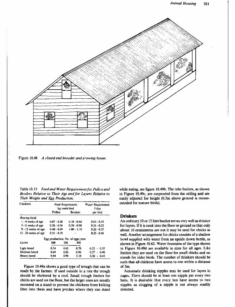
Animal Housing
Figure 10.48 A closed end brooder and growing house.
Table 10.15 Feed and Water Requirementfor Fullcts and Broilers Relative to Their Age andfor L.ayers Relative to Their Weight and .!$g Production.
Chickens Feed Requirments Water Requirement kg! week.bird WY
Pullets Broilers per bird
Recting birds I-4wecksofage 0.07 -0.20 o.io - 0.40 0.05 - 0.15 5-8weeksofage 0.26 -0.36 0.50 - 0.90 0.16-0.25 9- IZweeksofage 0.40 - 0.49 1.00 - 1.10 0.20 -0.35 13 - 20 weeks of age 0.51 -0.78 0.25 - 0.40
Egg production: No. of eggs/year Lqets ica 200 300
Light breed 0.54 0.65 0.78 0.25 - 0.35 Medium breed 0.69 0.82 0.94 0.27 - 0.40 Heavy breed 0.84 0.96 1.10 0.30 - 0.45
Figure 10.49a shows a good type of trough that can be made by the farmer. If used outside in a run the trough should be sheltered by a roof. Small trough feeders for chicks are used on the floor, but the larger ones are usually mounted on a stand to prevent the chickens from kicking litter into them and have perches where they can stand
while eating, see figure 10.49b. The tube feeders, as shown in Figure 10.49c, are suspended from the ceiling and are easily adjusted for height (0.3m above ground is recom- mended for mature birds).
Drinkers An ordinary 10 or 15 litre bucket serves very well as drinker for layers. If it is sunk into the floor or ground so that only about 10 centimetres are out it may be used for chicks as well. Another arrangement for chicks consists of a shallow bowl supplied with water from an upside down bottle, as shown in Figure 10.62. Water fountains of the type shown in Figure 10.49d are available in sizes for all ages. Lie feeders they are used on the floor for small chicks and on stands for older birds. The number of drinkers should be such that all chickens have access to one within a distance of 3m.
Automatic drinking nipples may be used for layers in cages. There shou!d be at least one nipple per every two hens. It is desirable that every hen have access to two nipples as clogging of a nipple is not always readily detected.

312
Figure 10.49a Trough
Figure 10.49~ Tube feeder
Figure 10.49 Feeders and waterer
Nest Boxes Layers and breeders, except those managed in cage sys- tems, should have access to nestboxes in which they can lay their eggs. The nests can be such that they can be used by one or more birds at a time. Single nests commonly have the dimensions 250 to 300mm wide, 300 to 380mm deep and 300 to 350mm high, have a 1OOmm litter retaining board across the bottom of the opening and have a perch IS0 to 200mm in front of the entrance. Communal nests should have a space allowance of at least 0.09m2 per bird. The top of the nest should be steeply sloped to prevent birds from roosting there. One nest should be supplied for every five bids in the flock. Figure 10.50 shows a two- tiered nestbox arrangement. The bottom row of nests should be 450 to 600mm off the floor.
Perches Chickens have a natural instinct to roost in trees at night. To provide for this perches are commonly installed in chicken houses from 6 to 8 weeks of age and after, in particular in semi-intensive systems. Perches for young birds should have a diameter of about 35mm and provide
Figure 10.49b Trough on a stand
Figure 10.49d Water fount
0.1 to 0.15m space per bird, while those for adult birds should be about 50mm diameter and provide 0.2 to 0.3m space. The perches should be fixed to solid stands, be 0.6 to 1 .Om above the floor, be 0.35 to 0.4m apart and preferably be placed lengthwise at the centre of the house. A deck about 2OOmm underneath to collect manure is desirable.
Feed Stores Grain stores are discussed in Chapter 9. The feed stores for a small flock would be very much like those shown for food grains. For the commercial flock, the type of store depends on how the Feed is handled. 1If it is purchased in bag lots, then a masonry building with an iron roof that is secure against rodents and birds is most suitable. If feed is deii- vered in bulk, then one or more overhead bins from which the feed is removed by gravity will be convenient and safe.
The size of the store required depends entirely on the frequency and size of deliveries, but can be estimated as 0.0035m2 floor area per bird in the flock where feed is purchased in bags. If part of the grain is produced on the farm, then some long term storage of the type shown in Chapter 9 will be required.
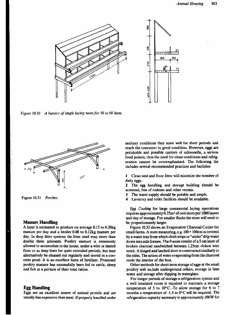
Animal Housing 313
Figure 10.50 A harrery of single layin,o nests for 50 to 60 hens.
Figure 10.51 Perches.
Manure Handling A layer is estimated to produce on average 0.15 to 0.20kg manure per day and a broiler 0.08 to 0.12kg manure per day. In deep litter systems the titter used may more than double these amounts. Poultry manure is commonly allowed to accumulate in the house, under a wire or slatted floor or as deep litter for quite extended periods, but may alternatively be cleaned out regularly and stored in a con- crete pond. It is an excellent form of fertiliser. Processed poultry manure has successfully been fed to cattle, sheep and f-h as a portion of their total ration.
Egg Handling Eggs are an excellent source of animal protein and are usually less expensive than meat. If properly handled under
sanitary conditions they store well for short periods and reach the consumer in good condition. However, eggs are perishable and possible carriers of salmonella, a serious food poison, thus the need for clean conditions and refrig- eration cannot be overemphasized. The following list includes several recommended practices and facilities:
1 Clean nest and floor litter will minimize the number of dirty eggs. 2 The egg handling and storage building should be screened, free of rodents and other vermin. 3 The water supply should be potable and ample. 4 Lavatory and toilet facilities should be avaiiable.
Egg Cooling for large commercial laying operations requires approximately 0.2Sm3 of cool store per 1000 layers and day of storage. For smaller flocks the store will need to be proportionately larger.
Figure 10.52 shows an Evaporative Charcoal Cooler for small farms. A store measuring, e.g. 100 x 1OOcm is covered by a water tray from which cloth strips or “wicks”drip water down into side frames. The frames consist of a 5 cm layer of broken charcoal sandwiched between 1.25cm chiken wire mesh. A hinged and latched door is constructed similarly to the sides. The action of water evaporating from the charcoal cools the interior of the box.
Other methods for short term storage of eggs at the small poultry unit include underground cellars, storage in lime water and storage after dipping in waterglass.
For longer periods of storage a refrigeration system and a well insulated room is required to maintain a storage temperature of 5 to 1O’C. JTo allow storage for 6 to 7 months a temperature of -1 .S to 0°C will be required. The refrigeration capacity necessary is approximately 200W for

314
5000 layers, or 34OOW for 10,000 layers. Other capacities would be proportionate. Custom designed systems with generous size evaporators should be installed. Room air- conditioners do not allow desirable humidity in a storage. The evaporator is too small and operates at a low tempera- ture, thus removing too much moisture from the air.
Figure 10.52 Evaporative coolerfor eggs, milk and other foodstuffs. Where electricity is available afan controlledair flow will make a more eficient operrition.
Duck Housing Although ducks are kept for both meat and egg produc- tion, commerciahy there is much more demand for meat than eggs.
On the other hand egg production does provide a valua- ble contribution to the family income and diet for the small scale farmer. Ducks lay more and larger eggs than indigen- ous chicken, Raising ducks is encouraged in African coun- tries because they are hardy and easy to raise and manage.
They can feed to a large extent on grass, vegetables and grains produced on tht farm. Housing is also quite simple and inexpensive. Small scale farmers would, for these rea- sons, benefit from keeping ducks instead of hens, which are more prone to disease and malnutrition.
Broodiug and Rearing Brood@: is similar to chickens and the same temperatures are used, 3S°C for the first week and then reduced 3’C weekly until normal air temperature is reached.
Ducklings grow very rapidly, and floor and trough space on deep litter should be provided according to Table 10.16.
Table 10.16 Recommended Minimum Floor and Feed Space for Ducks
Floor Spa@ Feed trough
SPafe rn’/ bird ’ birds/m* birds/m
I -2weeks 0.05 20 14 3 - 4 weeks 0.1 IO II 4 - 7 weeks 0.2 5 9 7 weeks to market 0.3 3-4 8 Mature birds 0.3 - 0.4 2.5 - 3 7-8 - 1 Refers to deep litter: on wire mesh floor the stocking can be doubled.
Litter materials include straw, sawdust, shavings and sand. The large quantity of water that ducks drink produ- ces wet manure that causes problems with almost any form of litter. A wire mesh floor therefore is a desirable altema- tive. The 12.Smm mesh of 8 gauge wire is suitable.
Fresh air is important and ducklings can be let out in fine weather after a few days. They should, however, not be allowed to get wet before the feathering is completed on their backs at about six weeks of age. Ducklings should also be shaded during hot weather to prevent sunstroke.
Housing Housing for ducks can be very simple. See Figure 10.53. The’house should be situated on a well drained, preferably elevated area.
7he f7oor should be raised at least 15cm above the surrounding ground level to help keep it dry. Ducks tend to be dirty and plenty of clean litter must be used in floor type housing.
Although a concrete floor can be installed for easy clean- ing, it is not necessary. If part of the floor is of wire mesh and the ducks have to cross it on their way to the nestboxes, their feet will be cleaned so they do not make the nests and eggs dirty.
Solid walls 6Ocm high are adequate. They may be made from any material as long as it keeps the ducks in and predators, hke dogs, snakes, rats and wild birds out. The space between the wall and theloof is covered with wire netting not larger than 2Smm mesh. Total wall heigh does not need to exceed 150-2OOcm.
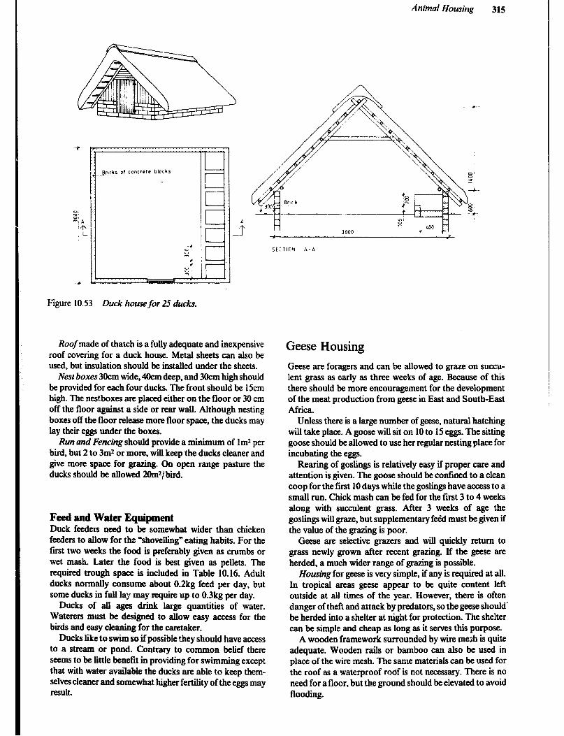
Animal Housing 315
Figure 10.53 Duck house for 25 ducks.
Roof made of thatch is a fully adequate and inexpensive roof covering for a duck house. Metal sheets can also be used, but insulation should be installed under the sheets.
Nesr boxes 3Ckm wide, 4Ocm deep, and 3oCm high should be provided for each four ducks. The front should be 15cm high. The nestboxes are placed either on the floor or 30 cm off the floor against a side or rear wall. Although nesting boxes off the floor release more floor space, the ducks may lay their eggs under the boxes.
Run and Fencing should provide a minimum of lm2 per bird, but 2 to 3m2 or more, wilI keep the ducks cleaner and give more space for grazing. On open range pasture the ducks should be ahowed 2Omr/bird.
Feed and Water Equipment Duck feeders need to be somewhat wider than chicken feeders to allow for the ~shovelling” eating habits. For the first two weeks the food is preferably given as crumbs or wet mash. Later the food is best given as pellets. The required trough space is included in Table 10.16. Adult ducks normally consume about 0.2kg feed per day, but some ducks in full lay may require up to 0.3kg per day.
Ducks of alI ages drink large quantities of water. Waterers must be designed to allow easy access for the birds and easy cleaning for the caretaker.
Ducks like to swim so if possible they should have access to a stream or pond. Contrary to common belief there seems to be little benefit in providing for swimming except that with water available the ducks are able to keep them- selves cleaner and somewhat higher fertility of the eggs may result.
Geese Housing
Geese are foragers and can be allowed to graze on succu- lent grass as early as three weeks of age. Because of this there should be more encouragement for the development of the meat production from geese in East and South-East Africa.
Unless there is a large number of geese, natural hatching will take place. A goose will sit on 10 to 15 eggs. The sitting goose should be allowed to use her regular nesting place for incubating the eggs.
Rearing of goslings is relatively easy if proper care and attention is given. The goose should be confined to a clean coop for the first 10 days while the goslings have access to a small run. Chick mash can be fed for the first 3 to 4 weeks along with succulent grass. After 3 weeks of age the goslings will graze, but supplementary feed must be given if the value of the grazing is poor.
Geese are selective grazers and will quickly return to grass newly grown after recent grazing. If the geese are herded, a much wider range of grazing is possible.
Housing for geese is very simple, if any is required at all. In tropical areas geese appear to be quite content left outside at all times of the year. However, there is often danger of theft and attack by predators, so the geese should’ be herded into a shelter at night for protection. The shelter can be simple and cheap as long as it serves this purpose.
A wooden framework surrounded by wire mesh is quite adequate. Wooden rails or bamboo can also be used in place of the wire mesh. The same materials can be used for the roof as a waterproof roof is not necessary. There is no need for a floor, but the ground should be elevated to avoid flooding.

316
Turkeys Housing In recent years there has been a steady increase in turkey production. The main demand is still at Christmas and New Year, but the better hotels and restaurants require supplies throughout the year. the demand is only for turkey meat. All the eggs produced are used for incubation by hatcheries.
The production of turkeys should be confined to com- mercial enterprises. Chickens carry diseases that affect turkeys so they should not be grown together by the small farmer.
Brooding and rearing methods for turkey poults are similar to those for chickens, but the brooding tetrnerature is higher. The recommended temperature for the first week is 35O to 38” C, after which it can be reduced 4’C per week until ambient temperature is reached.
Adequate floor space in the brooder house is important as the turkey poults grow rapidly. Table 10.17 provides information on space requirements.
At about 10 weeks of age, turkeys are put out on range in a fenced enclosure. In the interest of disease control, it is essential to use clean land that has not carried poultry, turkeys. sheep or pigs for at least two years. Approximately 2Omr of pasture should be allowed for each bud.
A range shelter with 20m2 of floor area is suitable for 100 poults up to marketing age. Dry, compact soil is adequate for a floor. The frame should be made of tight material covered with wire mesh so that the shelter can be moved to clean range each year. The roof, which should be water- tight, can be made of thatch or metal sheets. Perches, made from rails 5 x Scm or round rails 5cm in diameter, si,ould be installed 6Ocm from the ground and 60cm apart allowing 30 to 40cm of length per bid.
The turkey breeder flock can be confined in a deep titter house similar to the one shown in Figure 10.40 for chickens. Recommended floor, feed and water space for turkeys is given in Table 10.17. Approximately 23kg of feed is required to produce a 6.4kg turkey at 24 weeks of age. Adult birds require 0.12 to 0.3kg per day depending on the size of the breed.
Early mortahty in turkey poults due to lack of drinking or feeding is a constant problem and can only be prevented by good management and reliable equipment. Young poults must be coaxed to eat by making sure they have plenty of feeding places and can easily see the food. The same applies to water.
Table 10.17 Recommended Floor, Feed and Water Space for Turkeys
Brooding Growing Breeding 0-6weeks 6- 12weeks
Floor Space Roosting Space Nests
Feeders 4-8cm Water 2cm
O.lml 0.4 - 0.6m* 0.7 - 0.9m; 30 - 38cm 30 - 38cm
- M)m 15Ocm (for 20 - 25 hens)
IOcm I2cm 3cm 4cm
It is important to keep turkeys from being frightened by people, animals or machines. When alarmed, turkeys have a tendency to stampede, pile up and smother.
Sheep and Goat Housing Sheep and goats are important sources of milk and meat. Both readily adapt to a wide range of climates and availa- ble feed supplies. They also have similar housing require- ments and will therefore be treated together.
Management Systems Depending primarily on the availability and use of land, three systems of production are practiced:
1 Subsistance, in which a few animals are tethered during the day and put into a protective shelter at night. 2 Extensive, ‘in which the flock/herd grazes over large areas of marginal land unsuited to agriculture. The flock is usually shut into a yard at night. Both these systems are practiced extensively in East Africa. 3 Intensive. in which the animals are coutined to yards and shelters and feed is brought to the flock. This system offers the greatest protection for the flock from both preda- tors and parasites. Although it may make the best use of limited land resources, this system also increase labour and the capital investment required for facilities.
Housing Housing in tropical and semi-tropical regions should be kept to a minimum except for the more intensive systems of production. In the arid tropics no protection other than natural shade is required. In humid climates a simple thatched shelter will providt shade and protection from excessive rain. Sheep and goats do not tolerate mud well; therefore yards and shelters should be built only on well- drained ground.
Figure 10.54 shows a sheep/goat house for 100 animals. Unless predators are a serious problem, gum poles can be substituted for the brick walls. If thatching is difficult to obtain, a lower pitch roof of galvanized steel is feasible, but some insulation under the roof is desirable.
Where housing facilities are provided, it will be neces- sary to have in addition to water, feed troughs and per- manent partitions, provision for temporary panels to help divide and handle the flock when necessary to carry on such operations as disease treatment, docking, shearing, milking and lambing.
In temperate climates and at high altitudes a more sub- stantial structure may be needed; An open-front building facing north provides wind protection and a maximum of sunshine. A rammed earth floor with a slope of 1:50 toward the open front is recommended. X concrete apron sloped 1:25 and extending from 1.2m inside to 2.4m outside will help maintain clean conditions in the barn.
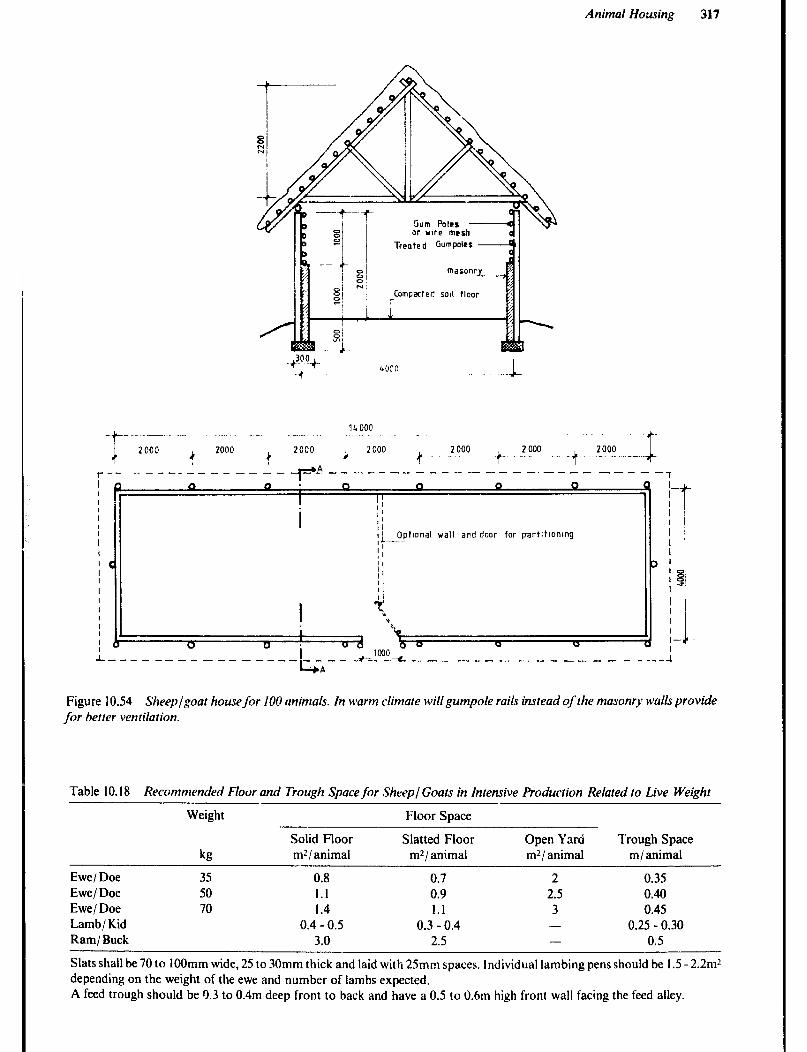
Animal Housing 317
Gum Poles - or wre mesh
Treated GumPoles -
masonry_ _
Compacted sod Hoor
I’ Opttonal wall and door for part!tlonlng , L--.- I’ I 1
I’ I’ I i 1 !
Figure 10.54 Sheep/goat house for 100 animals. In warm climate will gumpole rails instead of the n1asonr.s walls provide for better ventilation.
Table 10.18 Recommended Floor and Trough Space for Sheep/ Goats in Intensive Production Related to Live Weight
Weight Floor Space
Ewe/ Doe Ewe/ Doe Ewe/ Doe Lamb/ Kid Ram/ Buck
kg
35 50 70
Solid Floor Slatted Floor Open Yard Trough Space mZ/ animal mr/ animal ml/ animal m/animal
0.8 0.7 2 0.35 1.1 0.9 2.5 0.40 1.4 1.1 3 0.45
0.4 - 0.5 0.3 - 0.4 - 0.25 - 0.30 3.0 2.5 - 0.5
Slats shall be 70 to 1OOmm wide, 25 to 30mm thick and laid with 25mm spaces. lndividual lambing pens should be 1.5 -2.2m2 depending on the weight of the ewe and number of lambs expected. A feed trough should be Cl.3 to 0.4m deep front to back and have a 0.5 to 0.6m high front wall facing the feed alley.
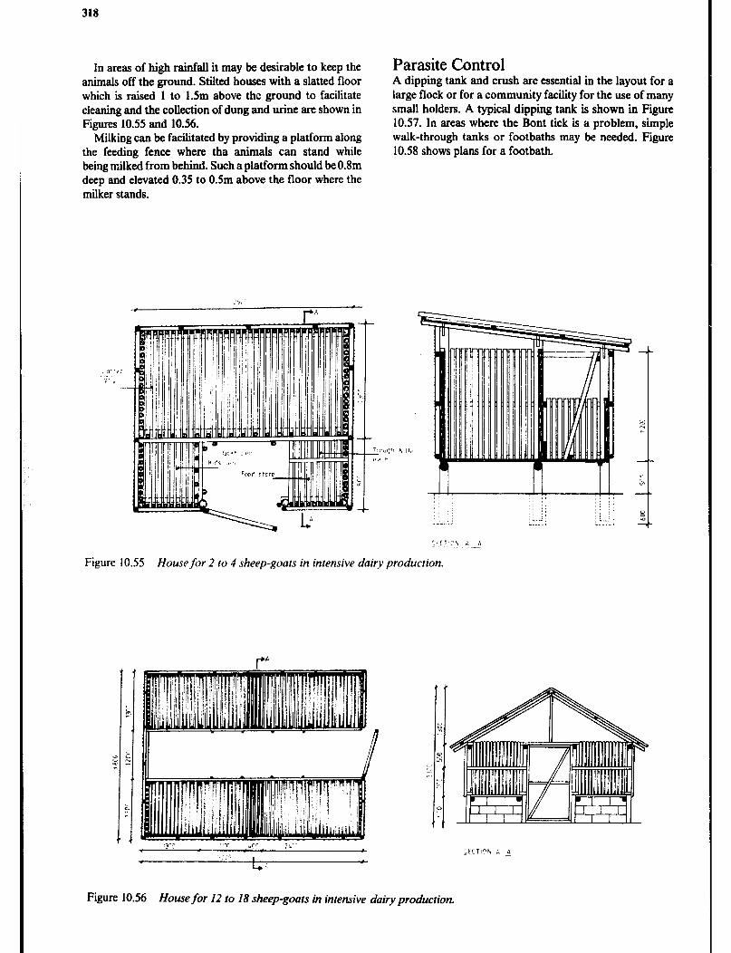
318
In areas of high rainfall it may be desirable to keep the animals off the ground. Stilted houses with a slatted floor which is raised 1 to 1.5m above the ground to facilitate cleaning and the collection of dung and urine are shown in Figures 10.55 and 10.56.
Milking can be facilitated by providing a platform along the feeding fence where tha animals can stand while being milked from behind. Such a platform should be O.Hm deep and elevated 0.35 to 0.5m above the floor where the milker stands.
Parasite Control A dipping tank and crush are essential in the layout for a large flock or for a community facility for the use of many small holders. A typical dipping tank is shown in Figure 10.57. In areas where the Bont tick is a problem, simple walk-through tanks or footbaths may be needed. Figure 10.58 shows plans for a footbath.
, .I . P i’
.i,‘, -
;i<r,cti ‘4
Figure 10.55 House for 2 IO 4 sheep-goats in intensive dairy production.
Figure 10.56 Home for I2 to 18 sheep-goats in intensive dairy production.

Anirnni housirrg 319
Figure 10.57 Sheep dipping tank.
Rabbit Housing There are few, if any, countries where domestic rabbits are not kept for meat and pelts. It is widely recognised that a few rabbits can be kept for a low cost, but yet produce a fair quantity of wholesome and tasty meat. However, to raise rabbits successfully one must begin with healthy animals, provide a good hutch, clean and nutritious feed and take good care of the rabbits.
Management Systems Rabbits like other domestic animals, may be bred and reared at various intensities. Table 10.19 shows some pro- duction characteristics related to this. Rabbits can be mated at almost any time and when mating is successful the doe will kindle 30 to 32 days later. The doe should be checked for pregnancy 10 days after mating and, if neces-
sary, re-mated. A shortened interval between kindling and mating will obviously result in increasing number of litters per doe and year. Commercial producers aim at getting at least 6 litters per year with 7 kids weaned per litter, i.e. 42 kids per doe each year. However, with intensive production the breeding doe may have to be replaced every one to 1.5 years, while in a semi-intensive system, she may last for 3 years. Replacement does can be bred for the first time at 5 months of age.
A balanced diet fed in adeql;ate amounts, good sanita- tion, disease control, appropriate housing and equipment and good care are all imptirtant factors when aiming at lower mortality and higher ciaily gain.
The mortality in a well managed rabbit unit should be below 20% from birth to slaughter among the young and he!ow 2O(;n snnually among the adults, but presently many extensive producers in East and South East Africa expe- rience mortality of up to three times that.
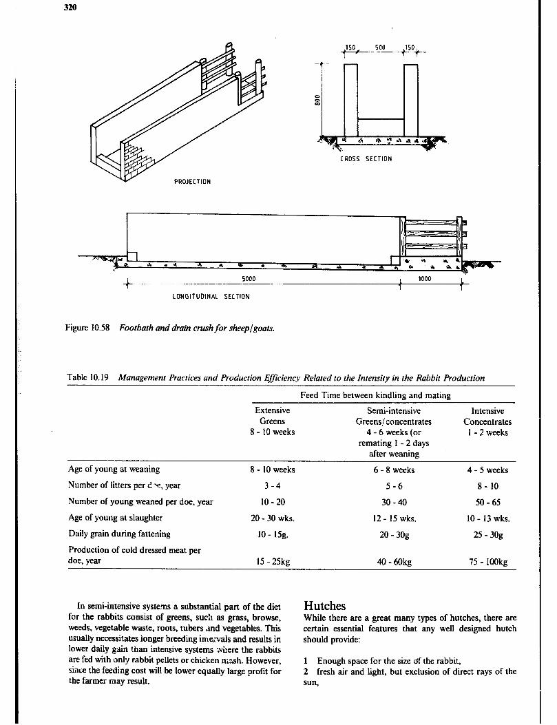
320
CROSS SECTION
+.---- 1000 - - .-.-- 5000 - 1 t 1 1
LONGITUDINAL SECTION
Figure 10.58 Footbath and drain crush for sheep/goats.
Table 10.19 Management Practices and Production Efficiency Related to the Intensity in the Rabbit Production
Feed Time between kindling and mating
Age of young at weaning
Number of litters 1 per Y, year
Number of weaned doe, young per year
Age of young at slaughter
Daily grain during fattening
Production of cold dressed meat per
doe, year
Extensive Greens
8 - 10 weeks
8 - 10 weeks
3-4
10 - 20
20 - 30 wks.
10 - 15g.
15 - 25kg
Semi-intensive Greens/ concentrates
4 - 6 weeks (or remating 1 - 2 days
after weaning
6 - 8 weeks
5-6
30 - 40
12- 15 wks.
20 - 3og
40-60kg
Intensive Concentrates
1 - 2 weeks
4 - 5 weeks
8- 10
50 - 65
10 - 13 wks.
25 - 30g
75 - 1OOkg
In semi-intensive systems a substantial part of the diet Hutches fcr the rabbits consist of greens, such as grass, browse, weeds, vegetable waste, roots, tubers ,md vegetables. This usually necessitates longer breeding irne,-vals and results in lower daily gain than intensive systems where the rabbits are fed with only rabbit pellets or chicken nzsh. However, since the feeding cost will be lower equally large profit for the farmer may result.
While there are a great many types of hutches, there are certain essential features that any well designed hutch should provide:
1 Enough space for the size of the rabbit, 2 fresh air and light, but exclusion of direct rays of the sun,

Animal Housing 321
3 protection from wind and rain, 4 sanitary conditions and ease of cleaning, 5 sound but cheap construction; which is free of details that could injure the animals, 6 convenience of handling, 7 a cage for each adult rabbit.
Space Requirement Each adult rabbit must have its own cage or compartment. Since domestic rabbits vary in weight from 2 to 7 kilos,
depending on breed, the size of cage may be determined by allowing 1200 to 15OOcm* of clear floor space per kilo of adult weight. This means that a cage for a medium breed buck should be minimum 8Ocm square. However, cages for temales should allow extra space for the nestbox and the litter, hence 80 by 115cm should be regarded as minimum for a medium breed doe.
Young rabbits reared for meat can be kept in groups of up to 20 to 30 animals until they reach four months of age. The weaned young kept in one group should be about the same age and weight. Such colony pens should allow 900 to 12OOcm* floor space per kilo of live weight.
The cages should not be deeper than 70 to 80cm for ease of reaching a rabbit at the back of the cage. The floor to ceiling height of the cages should be minimum 45 to 6Ocm and it is desirable to have the floor of the cages 80 to IOOcm off the ground to handle the rabbits comfortably.
Hutch Modules Any size rabbit unit is conveniently made up from two doe or four doe modules. The number of cages required in each of these modules is shown in Table 10.20.
The small scale producer may only have one such module, covered with its own roof, placed directly on the cages as shown in Figure 10.59 and 10.60; while the medium to large scale producer may have several modules
placed under a separate roof on posts or in a shed, as shown in Figure 10.61.
Construction Details Proper ventilation of the rabbitry is essential. The walls, roof and door of the hutch can be covered with chicken wire netting (37mm mesh) or made up of wood or bamboo placed 20mm apart.
In high altitude areas with lower temperatures it may be desirable to have a solid wall in the direction facing the prevailing wind. Temporary protection for strong winds, low temperatures and rain can be provided with curtains of hessian, reeds, grass, plastics, etc. The roof of the rabbit unit should be leak-proof and can be made of thatch or metal sheets with some insulation underneath.
Ease of management depends to a great extent on the construction of the floor. It may be solid, perforated, or semi-solid. Each has its advantages and disadvantages:
A solid floor can be made from wood, plywood or different kinds of boards. It allows bedding to be used, eliminates draughts through the floor and causes less trouble from hock sores, but is difficult to clean. The use of a solid floor will permit the hutches to be stacked in two or three tiers with the bottom row 30cm off the ground, and this may save some building space. However, a solid floor in the hutch frequently lead to outbreak of coccidbsis, a disease causing diarrhoea, loss of appetite and often death, because of build-up of manure in corners of the cage and contamination of feed and water.
A perforated floor is self-cleaning as manure and urine pass through to the ground and this assists in disease control, but if not properly constructed it may injure the animals. It can be made of woven or welded wire of not less than 16 gauge. Suitable mesh sizes are 12mm for small and medium breeds and 18mm for large breeds. Chicken wire can be used, but its thin wires may cause sore hocks and the urine can corrode the wire to failure within a year. The wire netting is streched over a wooden frame, trimmed flush with the bottom edge, and stapled every 5cm. Where it is fastened to posts the wire edges should be turned down to avoid injury to the rabbits. Self cleaning floor is usually recommended.
Table 10.20 Number of Hutches Required in 2 and 4 Doe Modules Depending on the Intensity of Feeding and Breeding
Cage Cages Cages for Total number for for fattening of cages per
Buck Does weaqers module
2 doe modules Extensive production 1 2 (1) 3 (or 4) Semi-intensive production I 2 1 4 Intensive production I 2 2 5
4 doe modules Semi intensive production I 4 3 8 Intensive production 1 4 4 (to 5) 9 (or IO)
Note: The cages for fattening weaners allow space for one litter
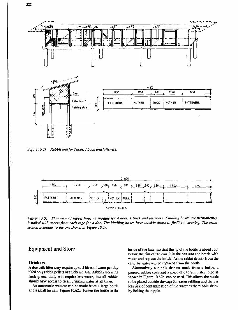
322
6600 7 .
1750 ,
1150 "
000 *
1150 L
1750 1
I 9
FATTENERS MCTtiER BUCK 1 MOTHER FATTENERS
I I
Figure 10.59 Rabbit unitfor 2 does, I buck andfatteners.
12 600
1750 _I 1750 ~ 950 L5OOL 950 ~ 800 L 950 csoo * 950 L 1750 0. 1750 'I 1 I 1 1 1 1 1 1 \
I/ !I
FATTENER MOTHER RUC1( I
1
I II
I
KIPPING BOXES
Figure 10.60 Plan view of rabbit housing module for 4 does, I buck and fatteners. Kindling boxes are permanently installed with access from each cage for a doe. The kindling boxes have outside doors to facilitate cleaning. The cross section is similar to the one shown in Figure 10.59.
Equipment and Store
Drinkers A doe with litter may require up to S litres of water per day if fed only rabbit pellets or chicken mash. Rabbits receiving fresh greens daily will require less water, but all rabbits should have access to clean drinking water at all times.
An automatic waterer can be made from a large bottle and a small tin can. Figure 10.62a. Fasten the bottle to the
inside of the hutch so that the lip of the bottle is about Icm below the rim of the can. Fill the can and the bottle with water and replace the bottle. As the rabbit drinks from the can, the water will be replaced from the bottle.
Alternatively a nipple drinker made from a bottle, a pierced rubber cork and a piece of 6 to 8mm steel pipe as shown in Figure 10.62b, can be used. This allows the bottle to be placed outside the cage for easier refilling and there is less risk of contamination of the water as the rabbits drink by licking the nipple.

Animal Housing 323
0 Q i
I
i
Figure 10.6 1 Rabbit housefor 16 to 18 does, 2 to 4 bucks and approximate1.v lOOfatteners. Note that hay racks have been installed between the cages for fatteners.
Feeders Heavy earthenware pots, about 8cm deep and 10 to 15cm diameter make good dishes for feeding grain, pellets and mash because they are not easily tipped over. Tin cans, free of sharp edges, or open sections of bamboo nailed to a small board can also be used. However, rabbits like to scratch out feed with their feet and to avoid this a feed hopper which is tied to the side of the hutch, can be made from an empty 5 litres oil tin as shown in Figure 10.6%. A 6 by 12cm flap is cut 6cm from the bottom and strengthened with a piece of timber and then bent inwards. The top of the tin is removed and the edges bent flat against the inside of the tin.
A manger made out of a piece of wire mesh, 40 by 4Ocm, can be fixed to the door of the cage for feeding greens or hay. This allows the rabbit to pull forage into the cage as it feeds. Greens should not be put on the cage floor as it increases the risk of disease. The remains of greens left on the floor must be removed every day.
Nests Does like to kindle in a private place. A nestbox should be placed in the doe’s cage 5 to 7 days before birth. A box for medium sized breeds should be about 30cm wide, 40 to 5Ocm long and 20 to 30cm high. A lid is sometimes supplied as some does prefer the nestbox to be dark and in cold weather the lid will conserve some heat for the kids. Straw or grass lining of the box is generally not necessary but will provide extra protection in cold weather. The box can be made of plywood, hardboard, wooden planks or even bamboo, but whatever is used it must be easily cleaned.
Feed Storage he storage requirement for feed to ail categories of animals in a rabbit unit can be deteJmined by multiplying the following figures with the number of &es in the unit and
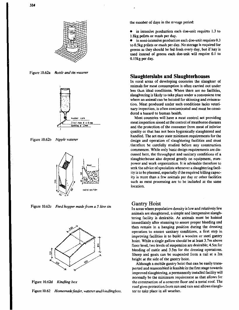
324
Figure 10.62a Bottle and tin waterer
Figure 10.62b Nipple waterer
CROSS SECT104
Figure 10.62~ Feed hopper made from a 5 litre tin
Figure 10.62d KindIirtg box
Figure 10.62 Homemadefeeder, waterer andkindlingbox.
the number of days in the stnrage period:
e in intensive production each doe-unit requires 1.3 to 1.8kg pellets or mash per day. 0 in semi-intensive production each doe-unit requires 0.3 to OSkg pellets or mash per day. No storage is required for greens as they should be fed fresh every day, but if hay is used instead of greens each doe-unit will require 0.1 to 0.15kg per day.
Slaughterslabs and Slaughterhouses In rural areas of developing countries the slaughter of animals for meat consumption is often carried out under less than ideal conditions. Where there are no facilities, slaughtering is likely to take place under a convenient tree where an animal can be hoisted for skinning and eviscera- tion. Meat produced under such conditions lacks veteri- nary inspection, is often contaminated and must be consi- dered a hazard to human health.
Most countries will have a meat control act providing meat inspection aimed at the control of meatbome diseases and the protection of the consumer from meat of inferior quality or that has not been hygienically slaughtered and handled. The act may state minimum requirements for the design and operation of slaughtering facilities and must thereiore be carefully studied before any construction commences. While only basic design requirements are dis- cussed here, the throughput and sanitary conditions of a slaughterhouse also depend greatly on equipment, man- power and work organization. It is advisable therefore to seek the advice of specialists whenever a slaughteringfacil- ity is to be planned, especially if the required killing capac- ity is more than a few animals per day or other facilities such as meat processing are to be included at the same location.
Gantry Hoist In areas where population density is low and relatively few animals are slaughtered, a simple and inexpensive slaugh- tering facility is desirable. As animals must be hoisted immediately after stunning to assure proper bleeding and then remain in a hanging position during the dressing operation to ensure sanitary conditions, a first step in improving facilities is to build a wooden or steel gantry hoist. While a single gallow should be at least 3.7m above floor level, two levels of suspension are desirable; 4.5m for bleeding of cattle and 3.5m for the dressing operations. Sheep and goats can be suspended from a rail at a 2m height at the side of the gantry hoist.
Although a mobile gantry hoist that can be easily trans- ported and reassembled is feasible in the first stage towards improved slaughtering, a permanently installed facility will normally be the minimum requirement as that allows for the construction of a concrete floor and a metal roof. The roof gives protection from sun and rain and allows slaugh- ter to take place in all weather.
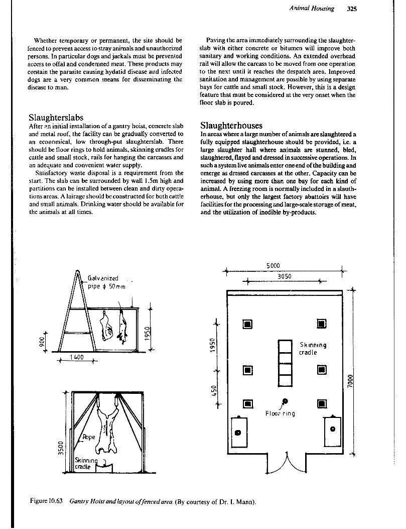
Animal Housing 325
Whether temporary or permanent, the site should be fenced to prevent access io stray animals and unauthorized persons. In particular dogs and jackals must be prevented access to offal and condemned meat. These products may contain the parasite causing hydatid disease and infected dogs are a very common means for disseminating the disease to man.
Slaughterslabs After ;In initial installation of a gantry hoist, concrete slab and metal roof, the facility can be gradually converted to an economical, low through-put slaughterslab. There should be floor rings to hold animals, skinning cradles for cattle and small stock, rails for hanging the carcasses and an adequate and convenient water supply.
Satisfactory waste disposal is a requirement from the start. The slab can be surrounded by wall I .5m high and partitions can be installed between clean and dirty opera- tions areas. A lairage should be constructed for both catt!e and small animals. Drinking water should be available for the animals at all times.
A Galvanized // \\ pipe 0 50mm i
Figure 10.63
Paving the area immediately surrounding the slaughter- slab with either concrete or bitumen will improve both sanitary and working conditions. An extended overhead rail will allow the carcass to be moved from one operation to the next until it reaches the despatch area. Improved sanitation and management are possible by using separate bays for cattle and small stock. However, this is a design feature that must be considered at the very onset when the floor slab is poured.
Slaughterhouses In areas where a large number of animals are slaughtered a fully equipped slaughterhouse should be provided, i.e. a large slaughter hall where animals are stunned, bled, slaughtered, flayed and dressed in successive operations. In such a system live animals enter one end of the building and emerge as dressed carcasses at the other. Capacity can be increased by using more than one bay for each kind of animal. A freezing room is normally included in a slauth- erhouse, but only the largest factory abattoirs will have facilities for the processing and large-scale storage of meat, and the utilization of inedible by-products.
.l 5000 1 3050
Skinning cradle
P ml Floor ring
l-
0
Gantry Hoist andlayout offencedarea. (By courtesy of Dr. I. Mann).

326
5: N m
. -
-
B c a.-.-,- \ ‘\
‘\ 5 LAUGHTER AREA f
CI BLEEDlNG s
\ Q / ‘\ -.-.-,-.-.-.-.-.- -..-.
DISPATCH I
-.‘-.- AREA
.w.. -,* ._._.-
cl \ _._.-.- ..-.- I
I L
-
RECORDS OFFKE
0
31
INSPECTION
WORK q TOP
=il
TRIPERY AND
-l EDIBLE OFFALS
-. -. -.-. -. \
SMALL STOCK 1 SLAUGHTER
i
L,-
aSMALL STMb --
1 14 550 1 +
Figure 10.64 Slaughterslab~iv slaughter of 20 cattle and 40 IO 50 sheep-goats per da-v. (By courtesy of Ministry of Local Government, Kenya).
SLAUGHTER AREA SKINNING OF CATTLE .-.--.-.A.‘-.-.-.-.- .-.-.-
1 Condrmnrd nwct
2. Work top
3. Trough
4. Equipmrnt star8
5. Stunning rtob
STOCK
Figure 10.65 Slaughterhouse/or slaughter of40 cattle and 40 to 60 sheeplgoatsper day. (By court&y of Ministry of Local Government, Kenya).

Animul Housing 327
Pig Slaughter Out of consideration for the Muslim population, pigs should be handled separately in a slaughterhouse designed and used only for that purpose. Reasons other than reli- gious also make it desirable to separate pig slaughtering. The steam from the scalding vats creates adverse condi- tions for setting of meat and the scurf accummulated from scraping pig carcasses is heavily contaminated with meat spoilage organisms. Pig slaughterhouse designs follow the same basic pattern as those for cattle, with provision for the separation of clean and dirty activities. The gallows and rails need to be 3.9m above floor level in the bleeding area and 2.5m in the slaughterhall. A water boiler to supply the xaldingvat with water of about 80°C will be required.
Poultry Slaughter Most poultry for local meat supply in rural areas is slaughtered singly or in small batches as the need arises and it is often carried act in the kitchen.
Only in areas where poultry is produced on a medium to large scale for supply of meat to an urban area, will the construction of a slaughterhouse for poultry be feasible.
General Recommendations for Design and Construction The site for a slaughter facility should be on ground that is higher than its surroundings to facilitate drainage. An adequate water supply must be available nearby to allow the slaughtering operations to be carried out under sani- tary conditions. An all weather road will ensure timely dispatch of the meat throughout the year. All trees and bushes within 20m of the fenced area should be cleared to detract birds, insects, etc.
In tropical countries slaughterhouses should be as open to the air as possible and the building designed so that even a light breeze will produce a ventilating draught. The open- ings should not be glazed, but should, along with grills in the roof ridging, be screened to prevent the entry of insects. The grills will allow the warm air to escape and cooler air to be drawn in through the windows.
For sanitary reasons, .loors and walls should be easily cleaned, impervious to water and rodent-proof. Concrete floors should be finished smoothly, but not to the extent of being slippery, and sloped towards the open drains along the walls. Concrete blocks or stone building blocks are preferred for wall construction. All joints should be smoothly linished and wall and floor junctions will be much easier to keep clean if they are finished with a cove.
L-L-LA-.; HANGING AREA
2 Scalding vat
3 Condemned meat
2730
Figure 10.66 Pig slaughterhouse for 20 to 30 animals per day.
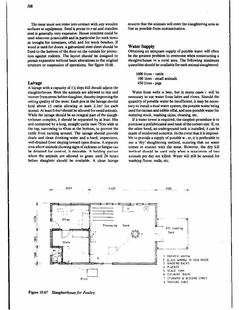
The meat must not come into contact with any wooden surfaces or equipment. Steel is prone to rust and stainless steel is generally very expensive. Hence concrete could be used wherever practicable and in particular for such items as troughs for intestines, offal, and for work benches. If wood is used for doors, a galvanized steel sheet should be fixed to the bottom of the door on the outside for protec- tion against rodents. The layout should be designed to permit expansion without basic alterations to the original structure or suspension of operations. See figure 10.68.
ensures that the animals will enter the slaughtering area as free as possible from contamination.
Water Supply Obtaining an adequate supply of potable water will often be the greatest problem to overcome when constructing a slaughterhouse in a rural area. The following minimum quantities should be available for each animal slaughtered:
Lairage A lairage with a capacity of 1% days hill Jhould adjoin the slaughterhouse. Here the animals are allowed to rest and recover from stress before slaughter, thereby improving the setting quality of the meat. Each pen in the lairage should hold about 15 cattle allowing at least 2.3m2 for each animal. At least 0.6m2 should be allowed for small animals. While the lairage should be an integral part of the slaugh- terhouse complex, it should be separated by at least 1Om and connected by a long, straight cattle race 75cm wide at the top, narrowing to 45cm at the bottom, to prevent the cattle from turning around. The lairage should provide shade and clean drinking water and a hard, impervious, well-drained floor sloping toward open drams. A separa!e area where animals showing signs of sickness or fatigue can be detained for control, is desirable. A holding pasture where the animals are allowed to graze until 24 hours before slaughter should be available. A clean lairage
1000 fi tres - cattle 100 &es - small animals 450 litres - pigs
Water from wells is best, but in many cases ir will be necessary to use water from lakes and rivers. Should the quantity of potable water be insufficient, it may be neces- sary to install a dual water system, the potable water being used for carcass and edible offal, and non-potable water for watering stock, washing skins, cleaning, etc.
If a water tower is required, the simplest procedure is to purchase a prefabricated steel tank of the correct size. If, on the other hand, an underground tank is installed, it can be made of reinforced concrete. In the event that it is impossi- ble to provide a supply of potable w .: er, it is preferable to use a ‘dry’ slaughtering method, ensuring that no water comes in contact with the meat. However, the dry kill method should he used only when a maximum of two animals per day are hilled. Water will still be needed for washing floors, walls, etc.
1 DISPATCH WINDOW
2 GLASS WINDOW TO VIEW INSIDE 3 SINGEING RACKS
4 PLUCKER
.
:.
?zl
5 SCALD TANK 6 CLEANING BASIN
Orcln 7 STUNNING B BLEEDING CONES
8 3RESSlNG TABLE
Figure 10.67 Stkughterhouse for Poultry.

Animal Housing 329
Park cng Area
Septic tank ,r.-.-.-c.”
F+- / i To coa kauay
Figure 10.68 Slaughterhouse with essentialfacilities.
Disposal of Blood The large quantities of blood collected from the bleeding area should not be allowed to enter the main drainage system and cause pollution, and must not be mixed with water. Therefore, all the effluent from the stunning and bleeding area should be collected separately and led to an underground tank situated outside the building. The tank should be built with a tight-fitting, removable cover and be so constructed that the liquid can seep through the sides into the surrounding soil. the blood will eventually decom- pose and it should be necessary to clean the tank only occasionally.
To avoid objectional odours, the tank should be equipped with a screened ventilation pipe. In tropical areas the air in the pipe and the upper part of the tank will be warmed sufficiently during the day to cause circulation and air renewal in the tank.
The blood tank will operate satisfactorily only if the ground water level is below the level of the tank and the surrounding soil is pervious to water.
Removal of Manure and Condemned Meat The carcass should be dressed out rapidly and the offal inspected and taken to a separatyroom whZre it can be cut up and the stomach and guts opened, cleared of manure and flushed with water. The manure is taken to a manure pit outside the building, while the rinsing water is directed into the main drainage system.
Suspected or condemned material is taken to the room set aside for this purpose. At the end of the day it is
Lairage area/ IIt-
disposed of, together with inedible offal, in two concrete pits outside the building. The pits should be equipped with airtight locable covers.
Most of the material will slowly decompose and it will not be necessary to empty t’le pits. Incineration is not recommended as efficient incinerators are expensive both to buy and to operate and simple incinerators do not work satisfactorily and burn out quickly.
Drains As running water is used during slaughtering and floors are flushea clean, the floors should be sloped so that water and effluent run into open drains placed along the walls. All these drains should be connected by a central drain to a grease and solids trap. From this trap the remaining efflu- ent is led either into an evaporation pan where bacterial action will break down most of the effluent in 20 to 30 days, or alternatively, into a sub-surface seepage field, designed with a series of herringbone patterned trenches filled with stones.
Soakage pits not less than 6m deep and 1.8m in diameter and Covered with a concrete top are satisfactory for only the smallest units. Open drains are recommended for the effluent from the slaughterhouse for the following reasons:
a it is often difficult to obtain the right type of piping in rural areas, whereas open drains can be cast as the floor is installed, b the quantity of water available is sometimes insufficient

330
to ensure that a system using closed pipes is adequately flushed and clogged pipes may result; c it is often difficult to obtain &ticient slope to allow the flushing action to take place by gravity so that automatic pumps would need to be installed - an expensive and impractical measure for a small slaughter operation.
To prevent rodents from entering, a screen should be fitted to the open dram where it passes through the slaugh- terhouserall in such a way that it can be easily removed for cleaning.
Cooling, Chilling and Freezing Rooms 4s soon as the carcasses have been dressed they should be removed from the slaughterhall to avoid prolonged expo-
sure to its atmosphere and thereby reduce the development of microflora in and cn the meat. Most meat in the tropics is distributed, still warm, for consumption the same day it is slaughtered. Hence a cooling room will normally not be required. The meat is instead transferred directly to a dispatch area. This practice implies that the work must start sufficiently early, and the slaughterslab, or slaughter- house must have capacity such that the slaughtering opera- tions can be finished by about 10 o’clock in the morning.
It is desirable to have a freezing room in all but the smallest slaughterhouses. The freezer can be used to steril- ize measled meat, since some types of meat parasites are destroyed by the 17,~ temperature. It also makes it possible to help to balance the supply of meat to the demand. Refrigeration units are expensive and a chill room where meat can be ripened and tenderized can be justified only where there is a demand for meat treated in such a wry.
Further Reading Agricultural Information Centre, Livestock Development Technical Handbook, Nairobi, Agricultural Information Centre. Attfield H.D., Raising Rabbits, Mt. Rainer M.D., Volunteers in Technical Assistance, VITA, 1977. Chakroff M., Freshwater Fish Pond Culture and Management, Mt. Rainer M.D., Volunteers in Technical Assistance,
VITA, 1978. Crees H.J.S., N&en-Petersen E., Githari J.X., Cattle Tick Control, Ministry of Livestock Development, 1977, Nairobi. Department of Agriculture, Rabbit Keeping, I ‘. La. Rural Information Service, Ministry of Agriculture and Water
Development. Devendra C., Fuller M-F., Ptg Production in the Tropics, Oxford University Press, 1979. Devendra C., McLeroy G.B., Goat and Sheep Production in the Tropics, Intermediate Tropical Agriculture Series,
London, Longman Group Ltd., 1982. Ensminger M.E., The Stockman’s Handbook. Animal Agriculture Series, 5th Edn. Danville, Ill., The Interstate Printers &
Publishers, Inc., 1978. Eriksen P.J., SIaughterhouseandSIaughterslab Design and Construction, FAO Animal Production and Health Paper no. 9,
Rome, Food and Agriculture Organization of the United Nations, 1978. Eusebio J-A., Pig Production in the Tropics, Intermediate Tropical Agriculture Series, Harlow, Essex, Longman Group
Ltd., 1980. Francis P., Poultry Production in the Tropics, Intermediate Tropical Agriculture Series, London, Longman Group Ltd.,
1984. Hafez E.S.E., T?re Behavior of Domestic Animals, 3rd Edn, Baltimore, The Williams and Wilkins Co., 1975. Hall J.M., Sansoucy R., Open Yard Housingfor l’oung Cattle, FAO Animal Production and Health Paper, no. 16, Rome,
Food and Agriculture Organization of the United Nations, 1981. Kilgour R., Dalton C., Livestock Behaviour, u Pm tical Guide, London, Granada Publishing Ltd., 1984. Mann l., Bees are Wealth; A Handy Guide to Bee-keeping in East Africa, Nairobi, East African Liter&arc Bureau, 1976. Midwest Plan Service, Small Farms-Livestock Buildings and Equipment, Ames, Iowa, Midwest Plan Service, 1984. Midwest Plan Service, Structure and Environment Handbook, Ames, Iowa, Midwest Plan Service, 1983. Ministry of Agriculture and Water Development, Dairy Buildings and Equipment, Lusaka, Ministry of Agriculture and
Water Development, 1982. Ministry of Agriculture and Water Development, Tick Control 6y Spruying - Dipping, Lusaka, Ministry of Agriculture and
Water Development, 1982. Ngugi J.B.M., Chicken Production; Main Breedr, Breeding & Management, Nairobi, Kenya Literature Bureau, 1980. Nissen-Petersen E., Svantesson F., ManuaZof Construction of Cart/e Dips Nairobi; Veterinary Department, Kenya, 1977. Noton N.H., Farm Buildings, Reading, UK, College of Estate Management, 1982. Oluyemi J-A., Roberts F.A., Poultry Production in Warm Wet Climates, London, The Macmillan Press Ltd., 1979. Payne W.J.A., Cattle Production in the Tropics, Vol. 1, Tropical Agriculture Series, London, Longman Group Ltd., 1970. Price C.J., Reed J.E., Poultry Husbandry II, Notes for Students of Animal Husbandry, Rome, Food and Agricultural
Organization of the United Nations, 197 1. Whitalrer J.H., Agricultural Buildings and Structures, Reston V.A., Reston Publishing Company, 1979. Williamson G., Payne W.J.A., An Introduction to Animal Husbandry in the Tropics, 3rd edn., Tropical Agriculture Series,
London, Longman Group Ltd., 1978.

Chapter 11
Sundry Farm Buildings
Farm Workshop Facilities A workshop provides a focal point at the farmstead for the repair and maintenance of machines, implements and structures. It also provides a place where tools can be stored in an orderly manner, a store for supplies and spare parts, and a shelter where work can be carried out during inclement weather. A facility of this type should be availa- ble on every farm. The size and design of a workshop, however, should be commensurate with the size of the farm and the work to be: done in the shop.
The s.; dl holder may be adequately served with a tool storage crlpboard that can be locked for sec&y and a workbench with a simple homemade vice for holding toois while they are being sharpened or fitted with new handles. From this simple beginning a more complete facility may gradually evolve as the farm operation grows and more equipment is required. Since repair tools and supplies represent. a considerable investment, most farmers will want to store them in a secure place. Many small scale farmers will not require a separate store for this pu;pose, bt*t. u stored together with hand tools and small imple- ments, the number of items may motivate the farmer to build a storeroom by enclosing part of the workshop with solid walls. Figure 11.1 shows a simple work shelter and store suitable for repair work and the storage of small im$er snts. I !ote that the doors to the store may be designed with racks and hooks to hold suppiles and to ~1s. Fuels dnd other combustible materials should not be stored with the tools. A simple work bench and vice can also be housed under the shelter.
At the other extreme, a large ranch or commercial farm may need a separate building w,th extensive equipment for maintaining the farm machinery, tractors and vehicles. A farmer may also use his workshop to do routine repairs and preventive maintenance during the off season, to build or modify some of the equipment used on the farm and to prefabricate building elements to be used in construction projects.
The workshop facilities should be cost effective. That is, enough savings should bc realized from timely mainte- nance, re@s and construction projects to pay for the cost of the building and the necessary toois and equipment. Aithough it is difficult to put a monetary value on timeli- ness, there is 110 question that being able to make emer- gency repairs is important. Some farm operations (plant- ing, spraying, milking) are more sensitive than others to prolonged interruptions, and having facilities to complete repairs on the farm can reduce delays to a minimum.
Other factors. apart from the faml size, which will influ- ence :he tx!ent of the workshop facilities are the number and diversit] of machines, the availabiiity of service from dealers, and the interest and mechanical skill exhibited by
the farmer and farm labourers. If necessary, a skilled mechanic may ‘be employed. Without qualified personnel
to use the shop it becomes questionable in value and may even contribute to more frequent breakdowns and addi- tional expense due to careless work.
The workshop should be located close to the work centre of the fzrm and convenient to the farm home on ground that is well drained and sufficiently level to allow easy maneuvering of equipment. Where electric power is avail- able, proximity to the power source should be considered.
In tropical climates the workshop may be a simple pole structure with a non-flammable roof. Unless dust is a problem, it may be feasible to leave the sides open to provide good light and ventilation. Heavy-gauge wire net- ting can be used to make the area more secure without reducing light or ventilation. A pole structure of this sort can be enclosed with offcuts or corrugated steel at a later time, but if this is dane, there must be provision for several good-sized windows. While a simple earth floor is often satisfactory, concrete offers the advantages of an easily
Figure 11.1 Small farm ’ workshop with a secure .._ oreroom.
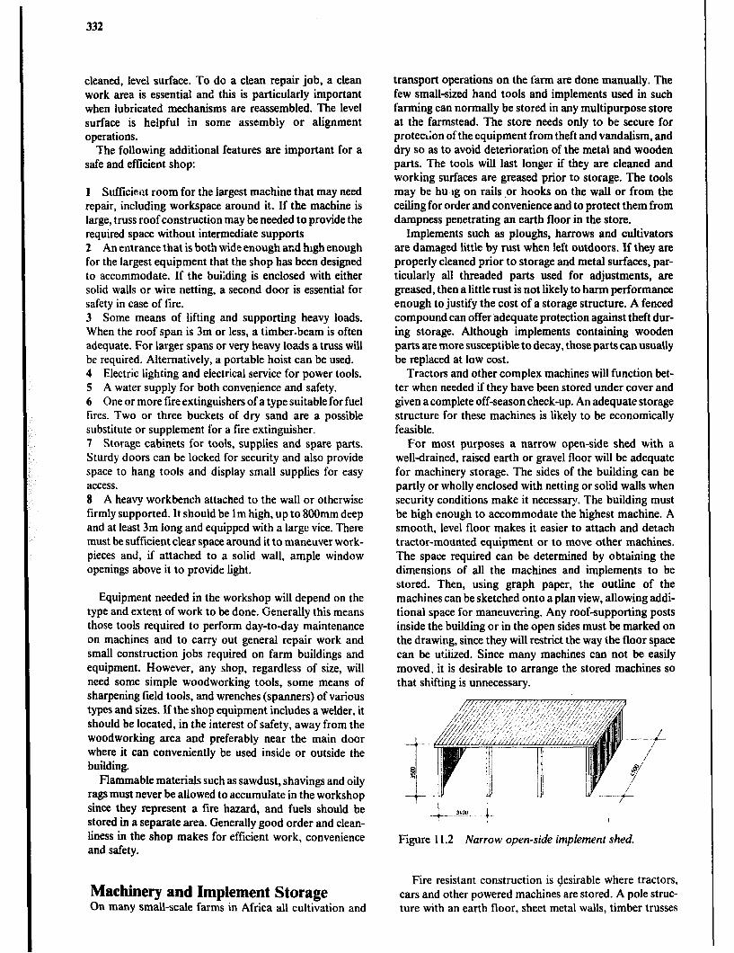
332
cleaned, level surface. To do a clean repair job, a clean work area is essential and this is particularly important when lubricated mechanisms are reassembled. The level surface is helpful in some assembly or alignment operations.
The following additional features are important for a safe and efficient shop:
1 Sufficient room for the largest machine that may need repair, including workspace around it. If the machine is large, truss roof construction may be needed to provide the required space without intermediate supports. 2 An entrance that is both wide enough ar.d high enough for the largest equipment that the shop has been designed to accommodate. If the building is enclosed with either solid walls or wire netting, a second door is essential for safety in case of fire. 3 Some means of lifting and supporting heavy loads. When the roof span is 3m or less, a timber-beam is often adequate. For larger spans or very heavy loads a truss will be required. Alternatively, a portable hoist can be used. 4 Electric lighting and electrical service for power tools. 5 A water supply for both convenience and safety. 6 One or more fire extinguishers of a type suitable for fuel fires. Two or three buckets of dry sand are a possible substitute or supplement for a fire extinguisher. 7 Storage cabinets for tools, supplies and spare parts. Sturdy doors can be locked for security and also provide space to hang tools and display small supplies for easy access. 8 A heavy workbench attached to the wall or otherwise firmly supported. It should be 1 m high, up to 80Omm deep and at least 3m long and equipped with a large vice. There must be sufficient clear space around it to maneuver work- pieces and, if attached to a solid wall, ample window openings above it to provide light.
Equipment needed in the workshop will depend on the type and extent of work to be done. Generally this means those tools required to perform day-today maintenance on machines and to carry out general repair work and small construction jobs required on farm buildings and equipment. However, any shop, regardless of size, will need some simple woodworking tools, some means of sharpening field tools, and wrenches (spanners) of various types and sizes. If the shop equipment includes a welder, it should be located, in the interest of safety, away from the woodworking area and preferably near the main door where it can conveniently be used inside or outside the building.
Flammable materials such as sawdust, shavings and oily rags must never be aliowed to accumulate in the workshop since they represent a iire hazard, and fuels should be stored in a separate area. Generally good order and clean- liness in the shop makes for efficient work, convenience and safety.
Machinery and Implement Storage On many small-scale farms in Africa all cultivation and
transport operations on the farm are done manually. The few small-sized hand tools and implements used in such farming can normally be stored in any multipurpose store at the farmstead. The store needs only to be secure for prote&on of the equipment from theft and vandalism, and dry so as to avoid deterioration of the metal and wooden parts. The tools will last longer if they are cleaned and working surfaces are greased prior to storage. The tools may be hu lg on rails .or hooks on the wall or from the ceiling for order and convenience and to protect them from dampness penetrating an earth floor in the store.
Implements such as ploughs, harrows and cultivators are damaged little by rust when left outdoors. If they are properly cleaned prior to storage and metal surfaces, par- ticularly all threaded parts used for adjustments, are greased, then a little rust is not likely to harm performance enough to justify the cost of a storage structure. A fenced compound can offer adequate protection against theft dur- ing storage. Although implements containing wooden parts are more susceptible to decay, those parts can usually be replaced at low cost.
Tractors and other complex machines will function bet- ter when needed if they have been stored under cover and given acomplete off-season check-up. An adequate storage structure for these machines is likely to be economically feasible,
For most purposes a narrow open-side shed with a well-drained, raised earth or gravel floor will be adequate for machinery storage. The sides of the building can be partly or wholly enclosed with netting or solid walls when security conditions make it necessary. The building must be high enough to accommodate the highest machine. A smooth, level floor makes it easier to attach and detach tractor-mounted equipment or to move other machines. The space required can be determined by obtaining the dimensions of all the machines and implements to be stored. Then, using graph paper, the outline of the machines can be sketched onto a plan view, allowing addi- tional space for maneuvering. Any roof-supporting posts inside the building or in the open sides must be marked on the drawing, since they will restrict the way the floor space can be utiiized. Since many machines can not be easily moved, it is desirable to arrange the stored machines so that shifting is unnecessary.
Figure 11.2 Narrow open-side implement shed.
Fire resistant construction is desirable where tractors, cars and other powered machines are stored. A pole struc- ture with an earth floor, sheet metal walls, timber trusses

Sundry Farm Buildings 333
and metal, asbestos-cement or sisal-cement roofing Will offer adequate tire resistance.
Machinery stores and farm workshops are constructed in much the same way and are usually placed close together for convenience. In fact, they may be housed in one build- ing with a workshop section at one end and machinery and implement storage in the balance of the building.
Fuel and Chemical Storage Many materials that are used on far.ns fall into the cate- gory of “hazardous matznals”, &ice they are either highly flammable or poisonovs. The type and quantities of these materials requiring stor;\ge will vary from one farm or one cooperative store to the next and only a few basic require- ments for safe storage will be considered here. Other mate- rials frequently used on farms such as fertilizers and cement also have special storage requirements mainly because they are hygroscopic, i.e.. they tend to pick up moisture from the atmosphere.
Storage of Hazardous Products Hazardous materials stored on farms normally include the following:
Highly flammable materials such as engine fuels and oils, such as petrol, diesel, kerosene and lubricating oils.
Gases such as butane, propane and acetylene. Oxygen promotes the combustion of other materials and must be handled carefully.
Paints containing flammable solvents, cellulose thinner or alcohol.
Poisonous materials such as herbicides, insecticides, rat poison and sheep and cattle dips.
Acids and alkalies such as detergents, cleaning liquids, lye and quicklime (CaO).
Medicines such as veterinary drugs and supplies. Some drugs may require refrigeration.
Wood preservatives and corrosion inhibiting paints.
Hazardous materials should always be stored in a separ- ate location containing only those materials. If the quanti- ties are larger, flammable and poisonous materials should be stored in separate rooms. Ideally each type of material should have its own storage space, that is, its own shelf in a cupboard or a storage room, or its own room in a coopera- tive or merchant store.
Quantities of flammable products greater than about 3 litres of cellulose thinner, 10 litres of petrol, 20 litres of kerosene, 50 litres of diesel fuel should be stored in a separate building at least 15m from any other building. For this purpose a pole building with steel netting walls offers shade and security.
Any store for hazardous products must be well venti- lated SO that explosive or toxic fumes can not accumulate. Ventilation openings should be provided at both low and high levels or altemalively the door can be covered with
netting. The store, including the ventilation openings, should be vermin proof to prevent rodents from breaking open packages. It must be possible to lock the store to prevent the theft of expensive materials and keep unautho- rised persons, in particular children, from accidentally coming into contact with the hazardous materials.
Some chemicals are harmful to the skin. Therefore wash- ing facilities should be available nearby for immediate use. Stores for hazardous materials should never have a drain in the floor as any spillage or wash-down water containing the materials must be prevented from entering any water- course or drinking water source. It is frequently recom- mended that the floor and lower part of the walis including the door sill be constructed of concrete to form a reservoir to contain any accidental spills. This type of store must be clearly Imarked with an appropriate warning notice.
Vent
c lJ-
/
i’ Figure 11.3 Cabinet .for the storage of chemicals.
Storage of Fertilizers and Other Non-hazardous Materials Some fertilizers are hygroscopic and easily pick up mois- ture from humid air or from the ground. This causes them to become lumpy and to deteriorate. Cement, although not very hygroscopic, will deteriorate if exposed to damp con- ditions. Other materials may be adversely affected by pro- longed exposure to high storage temperatures and there- fore must be shaded. Fertilizers and cement are normally sold in plastic lined bags offering some degree of protec- tion. They should be handled and stored so that the bags are not punctured or otherwise damaged. In addition the storage conditions should be as dry as possible. Bags should be placed on a raised platform in the store. This will allow ventilation and prevent ground moisture from pene- trating from below. The pile should be protected from rain by a roof or some other type ?f watertight cover. Fertilizer can be very corrosive to metals and should not be stored close to machinery or tools.
334
Greenhouses A greenhouse is a structure using natural light within which optimum conditions may be achieved for ths propagation and growing of horticultural crops, for plant research, or for isolating plants from disease or insects. While in the tropical areas of Africa there are only limited applications, there are a few situations in which a greenhouse can be justified because of the optimum growing conditions required for a high value crop or a research project.
There is a wide range in the cost of various greenhouse designs and a careful assessment to relate the requirements for a given enterprise to the cost of the house is important. For example, a greenhouse used for year long flower pro- duction can justify the cost of glass, while a house used for a month or two for starting vegetable plants can only justify a polythene covering.
Site and Support Facilities Greenhouses should be located in open areas with no shading from trees or buildings and with access to roads. The land should be nearly level and well drained with a fall of I in 100 to 1 in 200 being ideal. If possible, the site stould be sheltered from excessive winds. However, normal air movement is essential for natural ventilation systems and to prevent locally stagnant conditions.
Good soil is essential, deep. medium-textured loam being ideal. Soils which are less than ideal should be worth improving. Very heavy soils are not usually satisfactory.
Agood, clean water supply is of paramount importance. A full crop system may require up %I 8,4OOm-’ per hectare (8401/ mz) in a single year and the source of water must be able to supply all that will be required.
Electricity will be required if ventilation is to be mechan- ized and if stationary machinery is to be used in the greenhouse.
Design Parameters
Light It is important that the crops being grown in a greenhouse receive the optimum amount of tight, not only when the skies are clear (direct light), but also when it is cloudy (diffuse light).
The shape and construction of the house should be such that it will allow the best possible entry of light. The two shapes coming closest to the ideal are:
a the single-span semicircular section covered with clear polythene film, Figure 1 I .4. b the mansard profile, a framed structure in which the sides and two roof sections are sloped in such a way that a semicircular cross section is approximated, Figure 11.5.
The size and cross section of all the load bearing members have a pronounced effect on light transmission.
The gutters of multi-span roofs produce considerable shade, and likewise, in wide-span houses, the heavier roof trusses tend to cause more shading. Thus open trusses with narrow-section members are desirable.
Light colors and reflective surfaces improve light trans- mission. In spite of a good design for natural light, artificial lighting may be needed for the production of photo-period sensitive plants.
Orientation Within the latitudes found in the tropics it is desirable to orient the ridge of greenhouses north and south to reduce the overall shading by the framing members. This is true for all types of frames including multi-span houses.
Size While multi-span blocks of 3.2m each are least expensive to build, wider spans will allow somewhat better light transmission. Furthermore, the general management in wider houses (movement of machines, optimum cropping !ayouts, etc.) may justify the extra cost. As a general rule the cost is lowest when the length is four to five times the span width. This is particularly true with wide-span houses.
Height The height of a greenhouse should be sufficient for the operation of machinery and the comfort of the workers. An increase in height improves natural ventilation during still conditions and the desired plant climate is more easily obtained. However, with very high roofs, maintenance becomes more difficult. Gutter heights of 2.8 to 3.0m are recommended for multi-span houses to allow machines to move freely. In single-span houses, eave height should be at least 2m to allow for unrestricted work space.
Materials Greenhouses are generally built of steel, aluminium or wood and are glazed with good quality glass, clear poly- thene sheet, or fibreglass-reinforced polyester panels.
Szeel must be galvanized after fabrication as any welding or drilling breaks the galvanized layer. Steel is cheaper than aluminium and is ideal for the main roof frame.
Ahminium is very resistant to corrosion and is easily formed into complex sections. While it is expensive, it is most suitable for glazing bars. It cannot be economically welded and bolted construction is used.
Wood is less suitable for the lightweight construction and the high moisture conditions found in greenhouses, therefore only top grade timber of the most decay-resistant species which has been treated with a water-bourne type of wood preservative should be used.

Sundry Farm Buildings 335
--- Foundation tubes
I 200x200 Trench forburyingedgeof oolythene
Figure 1 I .4 Semicircular greenhouse frame.
MANSARD TYPE
24 3m
w-- 32om - . IOm 0, maw r
NARRUHI SPAN WIDE SP*N
GABLE TYPE
Figure I 1.5 Mansard and gable greenhouse frames.
Glass is expensive, but it is the most durable covering and transmits the most light (90%). However, the gradual build-up of dirt and algae along with surface etching even- tually causes a reduction in light transmission. The min- imum width of glass ordinarily used is 6IOmm. Also com- mon is the 730mm width. Both of these are 4mm thick and weigh Z.Skg/ mz.
Polythene sheet is increasingly being used to cover rela- tively low cost structures. It has light transmitting qualities similar to glass but the material has to be replaced periodi- cally as it deteriorates under the influence of ultraviolet light. However, the cost is much lower than glass and the roof framing can be much lighter, resulting in good economy.
Fibreglass reinforced polyester panels are more impact resistant than glass and more durable than polythene sheet. Light transmission is about 85% but drops off appreciably unless the surface is cleaned and resurfaced with acrylic sealer every 4 to 5 years. It is intermediate in cost between glass and polythene.
Ventilation In tropical regions ventilation is likely to be the most

336
important environmental control feature of the green- house. The exchange of air inside the building with air from the outside is used to lower temperature, reduce humidity, and to maintain a supply of carbon dioxide for photosynthesis. This is accomplished by natural means with vents and doors or by mechanical means with fans. A comprehensive discussion of ventilation is found in Chap- ter 7.
The ventilation rate is usually expressed as the cubic metres per second of airflow per square metre of floor area. To obtain a reasonable heat rise of less than 4OC in a glass-clad house, the airflow rate in the tropics should be 0.04 to O.O5mJ/s and m2 of floor area.
Polythene-clad houses do not become as hot due to the transparency of the plastic to longwave radiation which is transmitted back out of the house. Thus the ventilation rate for a polythene-clad house can be reduced to 0.03 to O.O4m3/s and m2. This further reduces the cost of a polythene-covered house.
Adequate natural ventilation is often provided by large doors at each end even though this may amount to only 3 to 7% of the floor area. These large doors not only aid in ventilation but also allow easy access to the greenhouse.
Cooling EvaporatiTe cooling can be used in greenhouses where ventilation alone is insufficient to maintain the required temperatures. Figure 11.6 shows the temperature reduc- tions possible with evaporative cooling. Evaporative cool- ing is discussed in detail in Chapter 7.
.u 6
-15 17 19 21 23 25 27 29
Ambient t cmperat urc ‘C Idry bulb1
Figure 11.6 Limits of evaporative cooling.
Shading Shading isised to reduce light transmission and heat gain when necessary. In glass houses shading may be done simply by applying water-based whitewash to the inside of the roof to cut down light transmission. When the weather conditions are steady and reliable, whitewash is cheap and effective and easily washed off when the need is past. Whitewash as a shade seems particularly appropriate for shading in tropical areas.
Further Reading Iowa State University, Planning and Equipping a Service Center for Your Farm, Ames, Iowa, Cooperative Extension
Service Iowa State University, 1980. Noton N.H., Farm Buildings. Reading, U.K., College of Estate Management, 1982. Virhammar K., Plastic Greenhouses for Warm Climates, FAO Agricultural Services Bulletin 48, Rome, Food and
Agriculture Organization of the United Nations, 1982. Whitaker J.H., Agricultural Buildings and Structures, Reston, Va., Reston Publishing Co., 1979. Food and Agriculture Organization, Agricultural Machinery Workshops: Design, Equipment and Management. FAO
Agricultural Development Paper No. 66, Rome, Food and Agriculture Organization of the United Nations, 1960.

Chapter 12
Farm Dwellings
The traditional life style of the farming communities of tropical Africa is undergoing many changes. People are becoming better educated, coming into contact with other cultures and technologies, and are gradually losing their knowledge of the traditional crafts and agricultural methods that were practiced by their ancestors. This is encouraging a change from the traditional way of life to a more modem, in some respects, westemised, mode of liv- ing with a desire for appropriate dwellings.
Planning the design and construction of a farm dwelling requires decisions with which the farm family must live for a long time, perhaps a lifetime. These decisions are likely to be highly personal because of individual preferences, financial situation, family size, location and other circum- stances. There are a number of factors to be considered and questions to be answered before building a home.
Hm rmador wdfh for me person
L~..Q.lL .* +.4loA . 1200 ;
Offlce chxr Dnmg ctm Arm char
Figure 12.1 Critical human space requirements.
i dbr
This chapter presents information relating to space requirements together with ideas for planning farm dwel- lings. It leaves a great deal of opportunity for designs to evolve through the cooperation of the farm family, crafts- men and perhaps engineers and architects. The planning will involve careful evaluation of factors such as traditional family culture and social life, climate, government reatia- tions, available materials and the skills of local craftsmen. The planning process will result in unique designs that may differ greatly from one area to another. However, only if the planning process aims at producing designs which within a cultural and environmental context are general in terms of layout, materials, construction and details, will they contribute to develop an indigenous building tradition that pursues the native architectural heritage.
Helpful information related to the platming of farm homes will be found in several other chapters including: Chapter 3-Materials, S-Building Construction, 7-Climate and Environment, &Functional Planning, and U-Water and Sanitation.
Space Requirements In planning a farm home, adequate spaceplust be allowed for each of the daily activities. This is not so much related to total space as it is to such things as door widths and heights, corridor widths, adequate space for a bed or a table and chairs, clearance for a door to swing open, etc. It is essential that these dimensions be checked in every .design as very minimal changes can often make a consider- able difference in convenience. Figure 12.1 as well as sev- eral figures in Section “Functional Requirements for dif- ferent rooms and spaces” provide a guide to space requirements.
Family Cultural and Social Requirements Various tribes and ethnic groups with different cultural and religious background have developed distinctive cus- toms and social requirements. An analysis of the farm family’s daily life, including present requirements and future plans, will help in selecting the important factors for designing an appropriate dwelling house.
A number of questions relevant to a farm home design are listed as follows:
Family size: How many persons will live in the house initially and in the future? What are the family relation- ships - age, sex, marital status?
Sleeping: Are separate bedrooms and/ or houses needed for the husband and wife (wives)? Where do small children sleep - in parents room, separate room nearby? Where do the older children sleep - separate room, separate house? Are children of different sexes separated?
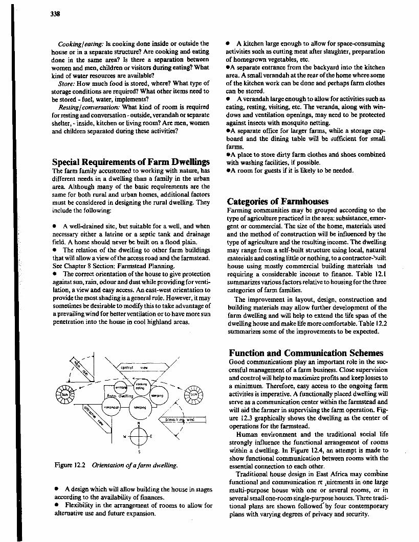
338
Cooking/eating: Is cooking done inside or outside the house or in a separate structure? Are cooking and eating done in the same area? Is there a separation between women and men, children or visitors during eating? What kind of water resources are available?
Store: How much food is stored, where? What type of storage conditions are required? What other items need to be stored - fuel, water, implements?
Resting/conversation: What kind of room is required for resting and conversation - outside, verandah or separate shelter, - inside, kitchen or living room? Are men, women and children separated during these activities?
Special Requirements of Farm Dwellings The farm family accustomed to working with nature, has different needs in a dwelling than a family in the urban area. Although many of the basic requirements are the same for both rural and urban homes, additional factors must be considered in designing the rural dwelling. They include the following:
0 A well-drained site, but suitable for a well, and when necessary either a latrine or a septic tank and drainage field. A home should never be built on a flood plain. l The relation of the dwelling to other farm buildings that will allow a view of the access road and the farmstead. See Chapter 8 Section: Farmstead Planning. l The correct orientation of the house to give protection against sun, rain, odour and dust while providing for venti- lation, a view and easy access. An east-west orientation to provide the most shading is ageneral rule. However, it may sometimes be desirable to modify this to take advantage of a prevailing wind for better ventilation or to have more sun penetration into the house in cool highland areas.
Figure 12.2 Urientation of afarm dwelling.
l A design which will allow building the house in stages according to the availability of finances. 0 Flexibility in the arrangement of rooms to allow for alternative use and future expansion.
0 A kitchen large enough to allow for space-consuming activities such as cutting meat after slaughter, preparation of homegrown vegetables, etc. *A separate entrance from the backyard into the kitchen area. A small verandah at the rear of the home where some of the kitchen work can be done and perhaps farm clothes can be stored. 0 A verandah large enough to allow for activities such as eating, resting, visiting, etc. The veranda, along with win- dows and ventilation openings, may need to be protected against insects with mosquito netting. *A separate office for larger farms, while a storage cup- board and the dining table will be sufficient for small farms. @A place to store dirty farm clothes and shoes combined with washing facilities, if possible. l A room for guests if it is likely to be needed.
Categories of Farmhouses Farming communities may be grouped according to the type of agriculture practiced in the area: subsistance, emer- gent or commercial. The size of the home, materials used and the method of construction will be influenced by the type of agriculture and the resulting income. The dwelling may range from a self-built structure using local, natural materials and costing little or nothing, to a contractor-%,& house using mostly commercial building materials md requiring a considerable income to finance. Table 12.1 summarizes various factors relative to housing for the three categories of farm families.
The improvement in layout, design, construction and building materials may allow further development of the farm dwelling and will help to extend the life span of the dwelling house and make life more comfortable. Table 12.2 summarizes some of the improvements to be expected.
Function and Communication Schemes Good communications play an important role in the suc- cessful management of a farm business. Close supervision and control will help to maximize profits and keep losses to a minimum. Therefore, easy access to the ongoing farm activities is imperative. A functionally placed dwelling will serve as a communication center within the farmstead and will aid the farmer in supervising the farm operation. Fig- ure 12.3 graphically shows the dwelling as the center of operations for the farmstead.
Human environment and the traditional social life strongly influence the functional arrangement of rooms within a dwelling. In Figure 12.4, an attempt is made to show functional communication between rooms with the essential connection to each other.
Traditional house design in East Africa may combine functional and communication re ,uirements in one large multi-purpose house with one or several rooms, or in several small one-room single-purpose houses. Three tradi- tional plans are shown followed2 by four contemporary plans with varying degrees of privacy and security.
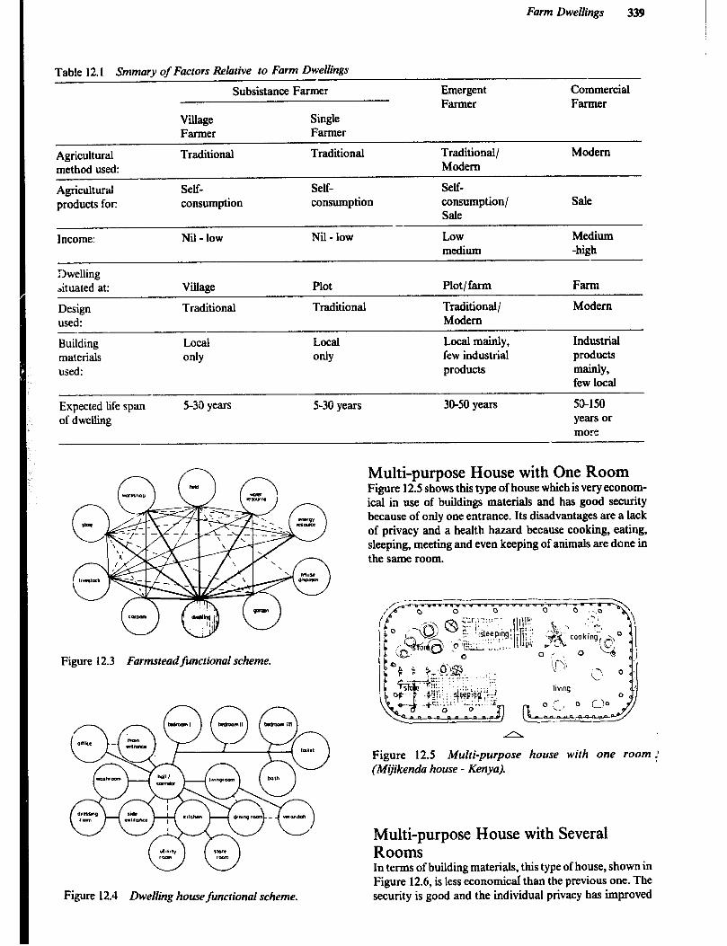
Farm Dwellings 339
Table 12.1 Smmary of Factors Relative to Farm Dwellings
Subsistance Farmer Emergent Commercial Farmer Farmer
Wage Single Farmer Farmer
Amiculturai Traditional Traditional Traditional/ Modem method used: Modem
Agricultural products for:
Income:
Dwelling ,ituated at:
Design used:
Building materials used:
Self- consumption
Nil - low
Village
Traditional
Local
OdY
Self- Self- consumption consumption/ Sale
Sale -
Nil - low Low Medium medium -high
Plot Plot/farm Farm
Traditional Traditional; Modem Modem
Local Local mainly, Industrial
OdY few industrial products products mainly,
few local
Expected life span of dwelling
5-30 years 5-30 years 30-50 years 5&150 years or more
Figure 12.3 Farmstead functional scheme.
ww
Figure 12.4 Dwelling house functional scheme.
Multi-purpose House with One Room Figure 12.5 shows this type of house which is very econom- ical in use of buildings materials and has good security because of only one entrance. Its disadvantages are a lack of privacy and a health hazard because cooking, eating, sleeping, meeting and even keeping of animals are done in the same room.
A
Figure 12.5 Multi-purpose house with one room ! (Mijikenda house - Kenya).
Multi-purpose House with Several Rooms In terms of building materials, this type of house, shown in Figure 12.6, is less economical than the previous one. The security is good and the individual privacy has improved
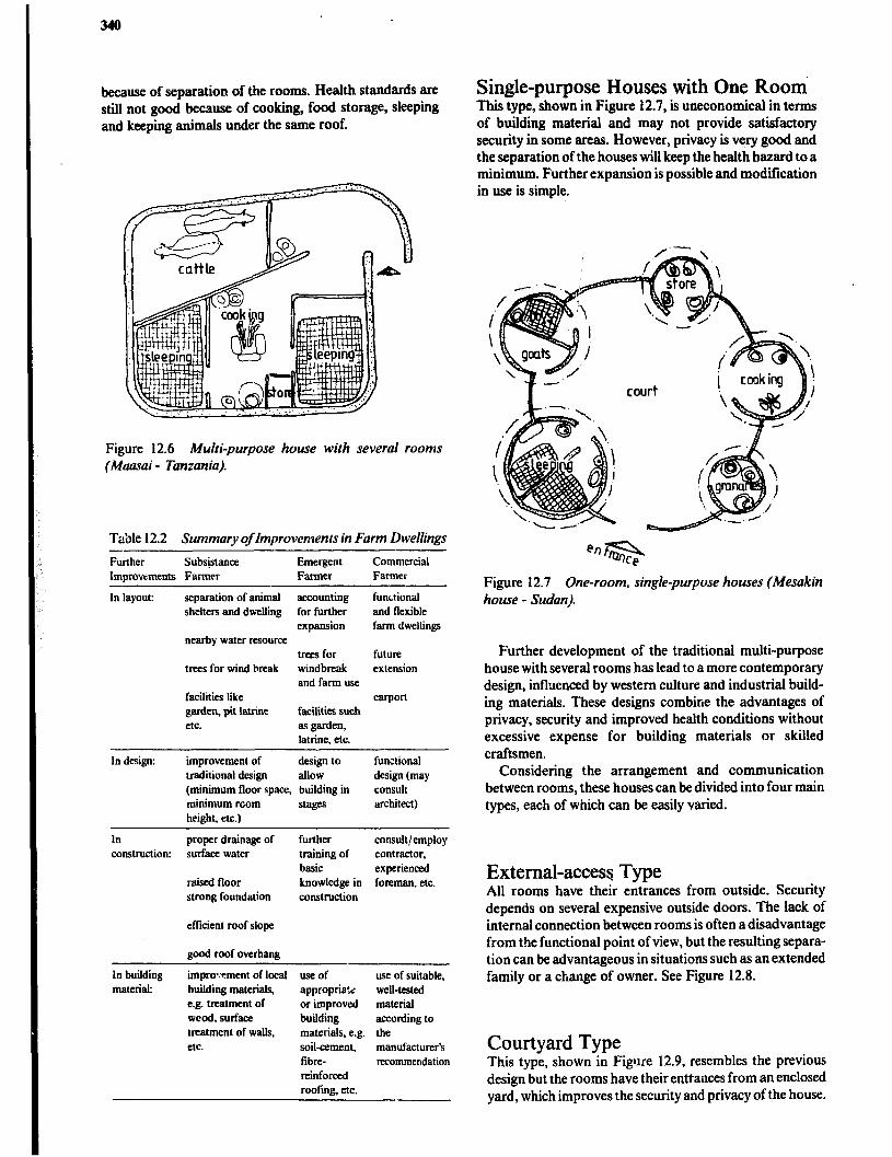
340
because of separation of the rooms. Health standards are still not good because of cooking, food storage, sleeping and keeping animals under the same roof.
Figure 12.6 Multi-purpose house with several rooms (Maasai - Tanzania).
Ta’ole 12.2 Summary of Improvements in Farm Dwellings - Further Subsjstance Emergent Commercial Improvements Farmer Farmer Farmer
In layout: separation of animal accounting functional shelters and dwelling for further and flexible
expansion farm dwellings nearby water resource
trees for future trees for wind break windbreak extension
and farm use facilities like carport garden, pit latrine facilities such etc. as garden,
latrine, etc.
In design: improvement of design to traditional design allow (minimum floor space, building in minimum room s&F he&$\ etc.)
functional design (may consult architect)
In proper drainage of further consuit/employ construction: surface water training of contractor,
basic experienced raised floor knowledge in foreman, etc. strong foundation construction
eflicient roof slope
good roof overhang
In building material:
impro*Yment of local building materials, e.g. treatment of wood. surface treatment of walls,
- use of appropria:c or improved building materials, e.g. soil-cement, fibre- reinforced roofing, etc.
use of suitable, well-tested material according to the manufacturer’s recommendation
Single-purpose Houses with One Room This typ, shown in Figure 12.7, is uneconomical in terms of building material and may not provide satisfactory security in some areas. However, privacy is very good and the separation of the houses will keep the health hazard to a minimum. Further expansion is possible and modification in use is simple.
Figure 12.7 One-room, single-purpose houses (Mesakin house - Sudan).
Further development of the traditional multi-purpose house with several rooms has lead to a more contemporary design, influenced by western culture and industrial build- ing materials. These designs combine the advantages of privacy, security and improved health conditions without excessive expense for building materials or skilled craftsmen.
Considering the arrangement and communication between rooms, these houses can be divided into four main types, each of which can be easily varied.
External-access Type All rooms have their entrances from outside. Security depends on several expensive outside doors. The lack of internal connection between rooms is often a disadvantage from the functional point of view, but the resulting separa- tion can be advantageous in situations such as an extended family or a change of owner. See Figure 12.8.
Courtyard Type This type, shown in Figure 12.9, resembles the previous design but the rooms have their entrances from an enclosed yard, which improves the security and privacy of the house.
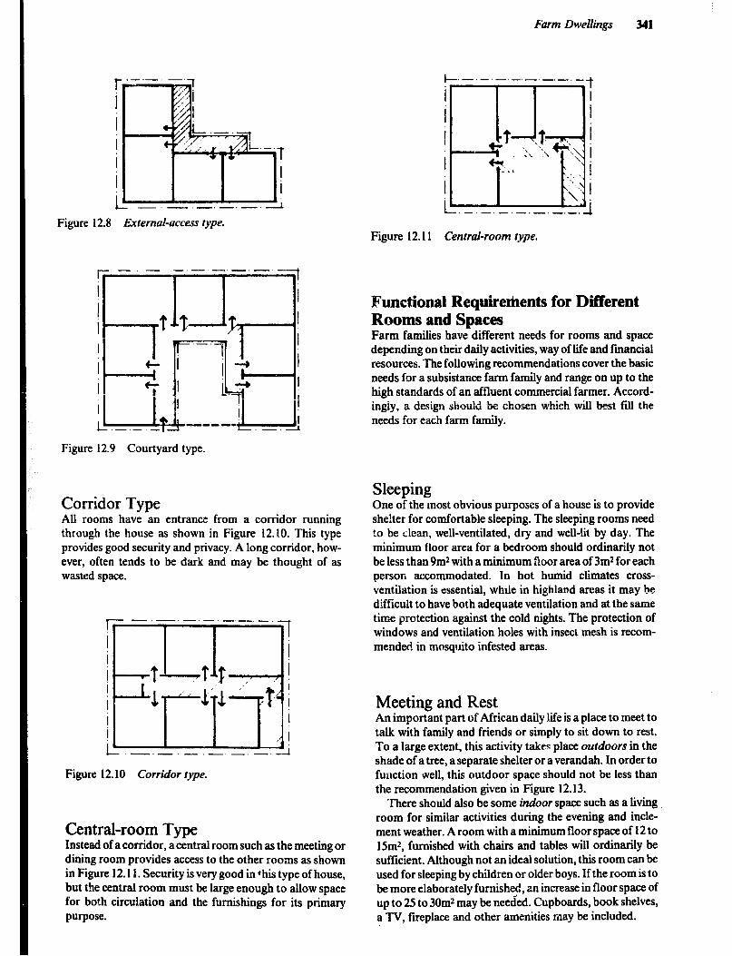
Farm Dwellings 341
r I I I i T i i
i _ -.-.-. -.-.-
Figure 12.8 External-access type.
Figure 12.9 Courtyard type.
Corridor Type All rooms have an entrance from a corridor running through the house as shown in Figure 12.10. This type provides good security and privacy. A long corridor, how- ever, often tends to be dark and may be thought of as wasted space.
r.-.-.-.- .-._._.
t
--!
ii
’ I i
, I i.-.-.-.-.-.-.- i
Figure 12.10 Corridor type.
Central-room Type Instead of a corridor, a central room such as the meeting or dining room provides access to the other rooms as shown in Figure 12.11. Security is very good in ‘his type of house, but the central room must be large enough to allow space for both circulation and the furnishings for its primary purpose.
Figure 12.11 Central-room type.
Functional Requirertrents for Different Rooms and Spaces Farm families have different needs for rooms and space depending on their daily activities, way of life and financial resources. The following recommendations cover the basic needs for a subsistance farm family and range on up to the high standards of an affluent commercial farmer. Accord- ingiy, a design should be chosen which will best fiu the needs for each farm family.
Sleeping One of the most obvious purposes of a house is to provide shelter for comfortable sleeping. The sleeping rooms need to be Llean, well-ventilated, dry and well-lit by day. The minimum floor area for a bedroom should ordinarily not be less than 9m2 with a minimum floor area of 3m2 for each person accommodated. In hot humid climates cross- ventilation is essential, whrle in highland areas it may be difficult to have both adequate ventilation and at the same time protection against the cold nights. The protection of windows and ventilation holes with insect mesh is recom- mended in mosquito infested areas.
Meeting and Rest An important part of African daily life is a place to meet to talk with family and friends or simply to sit down to rest. To a large extent, this activity takes place outdoors in the shade of a tree, a separate shelter or a verandah. In order to function well, this outdoor space should not be less than the recommendation given in Figure 12.13.
There should also be some indoor space such as a living room for similar activities during the evening and incle- ment weather. A room with a minimum floor space of 12 to lSm2, furnished with chairs and tables will ordinarily be sufficient. Although not an ideal solution, this room can be used for sleeping by children or older boys. If the room is to be more elaborately furnished, an increase in floor space of up to 25 to 30m2 may be needed. Cupboards, book shelves, a TV, fireplace and other amenities may be included.

Figure 12.12 Recommended sleeping spaces.
Figure 12.13 Minimum spacefor outdoor meeting/rest.
-5
g!
In m
I
8 ln -I
i-
-. --.__.- - __.-. J 1 min. 3000 I 1 1
Figure 12.14 Recommendedindoor spacefor meeting/rest.
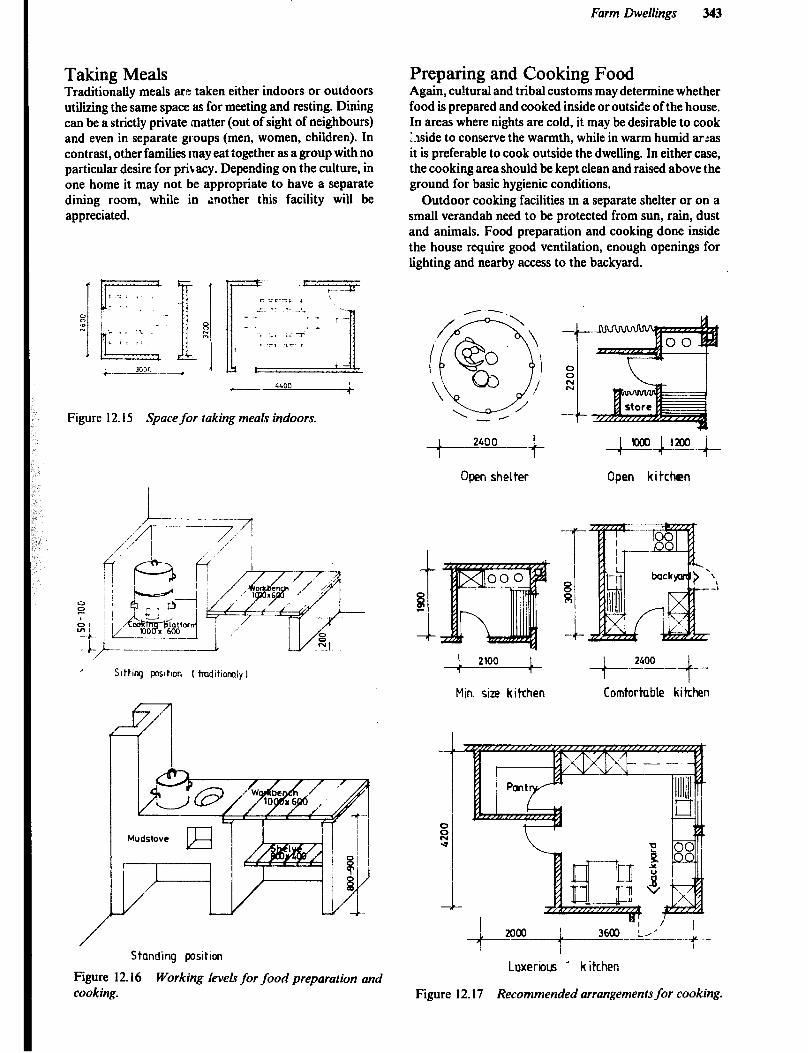
Farm Dwellings 343
Taking: Meals TraditioLally meals are taken either indoors or outdoors utilizing the same space as for meeting and resting. Dining can be a strictly private matter (out of sight of neighbours) and even in separate groups (men, women, children). In contrast, other families may eat iogether as a group with no particular desire for privacy. Depending on the culture, in one home it may not be appropriate to have a separate dining room, while in nother this facility will be
Figure 12.15 Spore for taking meals indoors.
, Slttlng poshon ( tmdhmiy I
/
Preparing and Cooking Food Again, cultural and tribal customs may determine whether food is prepared and cooked inside or outside of the house. In areas where nights are cold, it may be desirable to cook Aside to conserve the warmth, while in warm humid ar:as it is preferable to cook outside the dwelling. In either case, the cooking area should be kept clean and raised above the ground for basic hygienic conditions.
Outdoor cooking facilities in a separate shelter or on a small verandah need to be protected from sun, rain, dust and animals. Food preparation and cooking done inside the house require good ventilation, enough openings for lighting and nearby access to the backyard.
Open shelter Open kitchen
-I-
Min. size kitrhen Comfortable kitchen
Standing position
Figure 12.16 Working levels for food preparation and cooking.
+
Luxeriuus ’ kitchen
Figure 12.17 Recommended arrangements for cooking.

344
Combined mrkbench, shelves, rack, rail e)c
1 600-1200 t
Cupboard made of bricks and woodm shelves
Industr. produced kitchen turnlshmg
Figure 12.18 Storage of food and kitchen equipment.
Storage In a farm dwelling, space is needed to store foodstuff, kitchen equipment (pots, pans, dishes), clothing and bed- ding, fuel (firewood, charcoal), and perhaps some small farm tools (hoes, spades, pangas). The small things like foodstuff, kitchen equipment and textiles may be stored in the rooms for cooking, sleeping and meeting. Larger items need a separate store which can be another room in the house or part of an out-building. Kerosene should be stored outside of the house.
Kitchen utensils and foodstuff kept in pots or containers should be raised off the ground for storage. They may be either hung from the roof, placed on racks or shelves or in kitchen cabinets. For larger quantities of grain or produce, a separate store will be needed.
_--’ - ; *-I ------_ / *’ r L’- -I._ --- -6’ /’ . _- -. ,-__ -c- 3 L--==I:c-- .H / L-- / ;;: /r
--- I -71 8 ~c.....$pj 11 w I--Z- L-‘I t_--t’, --- ---- --.__ , .’ / / , l./ 1 600 1600 L 600
1 1
Cupbmd mode of wood with shelwi and dmuers. Cupbmd mode of wood with shelwi and dmuers.
Cupboard made of bcicks, wooden shelves, curtains
Figure 12.19 Storage for clothing and bedding.

Farm Dwellings MS
Clothing and bedding and small personal belongings should be stored in a clean, dry place, well-protected from dust. Boxes and built-in shelves are adequate and inexpen- sive. Cupboards are more convenient and more dustproof but are somewhat more expensive.
Recommendations for space for separate storerooms for foodstuff and larger items such as fuel and equipment are given in Figure 12.20.
:_---? - a I
--~_--- / -I- M in 5pace for mull ipupose store
Figure 12.20 Recommended spucrs for separate storerooms.
washing Personal washing (ablution) and washing of dishes and clothes is done either inside or outside the dwelling, depending on the availability and source of water (stream, lake, well, piped). If washing is done inside the house, it is important to take care of the waste water.
Welldrained surfaces and a properly constructed soak- away will avoid muddy areas and breeding places for mosquitos. Easily cleaned, waterproof materials should be used inside the house. Floors should slope towards a drain leading to a soakaway.
For washing dishes and clothes outside, an easily cleaned, hard surface of at least 3m* will be necessary. An open shelter and a work bench are recommended improvements. Clothes *washing inside the house is usually done in the bath or a separate utility room, while dishes are washed in a kitchen sink or in a basin.
Personal washing, if not done in a nearby stream or lake, can be done in a simple shelter constructed near the home. A drain and soakaway are essential. Section Aqua Privies in Chapter 14 discusses and illustrates a combination bathhouse and privy. Personal washing done inside the house requires a well-ventilated room finished with water- proof and easily cleaned materials. If piped water is available, a flush toilet is a desirable amenity. A septic tank aud drainage lield will be necessary with a flush toilet. Figure 12.21 shows space requirements and facility arrange- ments for various combinations ranging from a simple washroom to complete bath and toilet facilities.
Washiq Shower Both
Toilt t Toilet/Bath
Figure 12.21 Recommended space-for indoor toilet and bathing facilities.
Reading and Writing Education of the rural population is increasing steadily and places to read and write are becoming more essential for the farm home, especially for children going to school. While the sleeping room may provide the best place in terms of privacy, the meeting room and verandah are possible but less appropriate places for intensive studying. The farmer also needs a place to store documents and records and attend to the farm business. The dining table in combination with a cupboard is sufficient for the small farmer, while on a large farm, a separate oftice of about

9mZ of floor space may be required. Good natural lighting as well as artificial lighting are essential wherever reading and writing are done.
Entrance The traditional African house has an entrance protected from wind, rain and sun by a roof overhang which also provides privacy for the family. In a low cost farm dwelling the entrance may be combined with the verandah or the main meeting and resting room and is often used for additional storage space for equipment, farm clothing, bicycle, etc. A larger more modem farm dwelling should have at least two entrances, one at the front of the house where visitors are received and another near the kitchen or utility room which can be used for coming and going in the performance of daily work around the home and farmstead.
Improvement of Existing Dwellings In many cases, improvements can be made to existing homes similar to those shown in Figure 12.22 at little or no cost. For example, separating the animals from the dwel- ling and installing a well designed latrine should improve sanitary conditions. Developing a nearby water supply of adequate quantity and good quality will make the women’s life easier. A mud stove will save fire wood and contribute to forest resource conservation. However, the waste heat from a traditional fireplace may be needed for warming the home in cool climates.
Another improvement desirable h many rural homes is additional backfilling with soil to raise the floor level to 10 to 15 cm above the outside ground level. Unfortunately this will sometimes make ceiling and door heights undesirably low. Cut-off drains will also help to prevent surface water from entering the home. Although it may be difficult to install in an existing house, a waterproof foundation will be helpful in preventing moisture from penetrating the floor and lower walls.
Contemporary Farm Dwellings For the farm family that chases to use one of the expanda- ble systems shown in Figures 12.23 and 12.24, a number of local materials are suitable. A foundation of stone or brick masonry or concrete is desirable, but then adobe blocks, mud and poles or stabilized soil blocks are suitable for the walls. While corrugated steel makes a clean, leakproof and durable roof, where it is available, thatch is less expensive and perfectly satisfactory. Thatch will require a roof slope of approximately 450 and the frame should be build high enough to allow the eaves to be a minimum of 2m above the ground. An overhang in the verandah areas will require support as shown in the figures.
When resources allow, the same designs shown in Figure 12.23 and 12.24 may be built with concrete foundations and floors, along with durable masonry walls of brick, concrete blocks and other available material. The tempera- ture extremes typical of corrugated roofs can be reduced with the installation of insulated ceilings. The final result will be a secure, easily cleaned and durable home. Although considerably more expensive than dwellings made compleiely of !ocal materials, this type of construc- tion should be feasible ior the emerging farmer who is producing some crops or ammals for the commercial market.
----- -.
1w
H m
&! j
L- - \J
Figure 12.22 TradirionaI homes for sleeping or sIeeping and cooking.
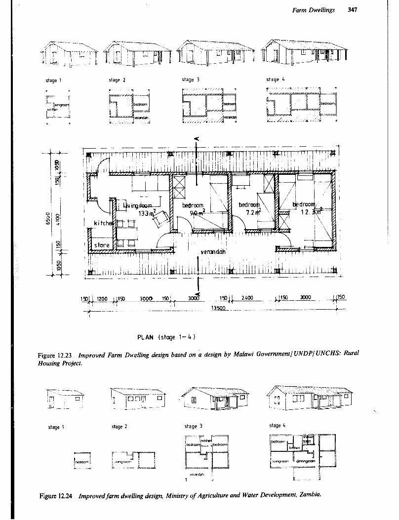
Farm Dwellings
stage 1 stage 2 stage 3 stage 4
I ,.-. .I ,v , I
I
) , I
1 I
1 i I - k i /
-.- -..- -- - -
PLAN (stage 1-G 1
Figure 12.23 Housing Project.
Improved Farm Dwelling design based on a design by Malawi Governmenll UNDP/ UNCHS: Rural
stage 1 stage 2 stage 3 stage 4
Figure 12.24 Improvedfarm dwelling design, Minbrry of Agriculture and Water Development, Zambia.

348
Further Reading Andersen K.B., African Traditional Architecture, A Study of the Housing and Settlement Patterns of Rural Kenya,
Nairobi, Oxford University Press, 1977. Enzmann J., Farm Dwellings, Lusaka, Ministry of Agriculture and Water Development, 1984. Kaszner O., Guidelinesfor Room Tvpes in Low-cost Housing, with Reference to the Highland Chmatic Region, Nairobi,
Housing Research and Development Unit - University of Nairobi, 1977. Neufert E., Architect’s Data - Handbook of Building Types, 2nd edition., London, Granada Publishing Ltd., 1980. Olesen F., Low-income House Types for Kenya, a Selection of House Types with Estimated Construction Cost Prices,
Suitablefor the Low-income Group, Nairobi, Housing Research and Development Unit - University of Nairobi, 1979. Schreckenhach H., Aba,.: .wa J.G. K., Construction Technoiogyfor a Tropicai Developing Country, Eschborn, German
Agency for Technical Co-operation (GTZ), 1982. Svard C.. Rural Low-cost Houses. Advice Concerning Design and Choice of Materialsfor Rural Housing in Tanzania,
Technical Pamphlet no. 3, Dar es Salaam, National Housing and Building Research Unit, 1980.
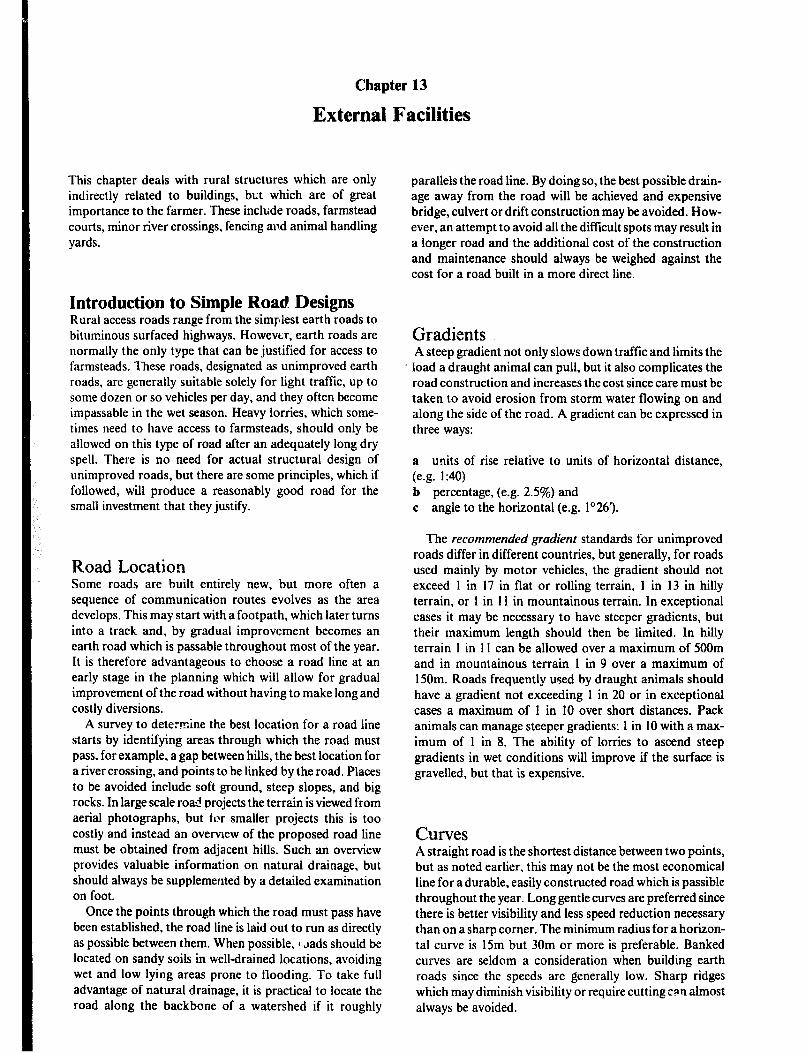
Chapter 13
External Facilities
This chapter deals with rural structures which are only indirectly related to buildings, but which are of great importance to the farmer. These include roads, farmstead courts, minor river crossings, fencing and animal handling yards.
Introduction to Simple Road Designs Rural access roads range from the simplest earth roads to bituminous surfaced highways. However, earth roads are normally the only type that can be justified for access to farmsteads. These roads, designated as unimproved earth roads, are generally suitable solely for light traffic, up to some dozen or so vehicles per day, and they often become impassable in the wet season. Heavy lorries, which some- times need to have access to farmsteads, should only be allowed on this type of road after an adequately long dry spell. There is no need for actual structural design of unimproved roads, but there are some principles, which if followed, will produce a reasonably good road for the small investment that they justify.
Road Location Some roads are built entirely new, but more often a sequence of communication routes evolves as the area develops. This may start with a footpath, which later turns into a track and, by gradual improvement becomes an earth road which is passable throughout most of the year. It is therefore advantageous to choose a road line at an early stage in the planning which will allow for gradual improvement of the road without having to make long and costly diversions.
A survey to dete.?r,ine the best location for a road line starts by identifying areas through which the road must pass, for example, a gap between hills, the best location for a river crossing, and points to be linked by the road. Places to be avoided include soft ground, steep slopes, and big rocks. In large scale road projects the terrain is viewed from aerial photographs, but for smaller projects this is too costly and instead an overvrew of the proposed road line must be obtained from adjacent hills. Such an overview provides valuable information on natural drainage, but should always be supplemented by a detailed examination on foot.
Once the points through which the road must pass have been established, the road line is laid out to run as directly as possible between them. When possible, 1 Jads should be located on sandy soils in well-drained locations. avoiding wet and low lying areas prone to flooding. To take full advantage of natural drainage, it is practical to locate the road along the backbone of a watershed if it roughly
parallels the road line. By doing so, the best possible drain- age away from the road will be achieved and expensive bridge, culvert or drift construction may be avoided. How- ever, an attempt to avoid all the difficult spots may result in a longer road and the additional cost of the construction and maintenance should always be weighed against the cost for a road built in a more direct line.
Gradients A steep gradient not only slows down traffic and limits the load a draught animal can pull, but it also complicates the road construction and increases the cost since care must be taken to avoid erosion from storm water flowing on and along the side of the road. A gradient can be expressed in three ways:
a units of rise relative to units of horizontal distance, (e.g. 1:40) b percentage, (e.g. 2.5%) and c angle to the horizontal (e.g. l”261.
The recommended gradient standards for unimproved roads differ in different countries, but generally, for roads used mainly by motor vehicles, the gradient should not exceed 1 in 17 in flat or rolling terrain, 1 in 13 in hilly terrain, or 1 in 11 in mountainous terrain. In exceptional cases it may be necessary to have steeper gradients, but their maximum length should then be limited. In hilly terrain 1 in 1 I can be allowed over a maximum of 5OOm and in mountainous terrain 1 in 9 over a maximum of 150m. Roads frequently used by draught animals should have a gradient not exceeding 1 in 20 or in exceptional cases a maximum of 1 in 10 over short distances. Pack animals can manage steeper gradients: 1 in 10 with a max- imum of 1 in 8. The ability of lorries to ascend steep gradients in wet conditions will improve if the surface is gravelled, but that is expensive.
Curves A straight road is the shortest distance between two points, but as noted earlier, this may not be the most economical line for a durable, easily constructed road which is passible throughout the year. Long gentle curves are preferred since there is better visibility and less speed reduction necessary than on a sharp comer. The minimum radius for a horizon- tal curve is 15m but 30m or more is preferable. Banked curves are seldom a consideration when building earth roads since the speeds are generally low. Sharp ridges which may diminish visibility or require cutting tan almost always be avoided.
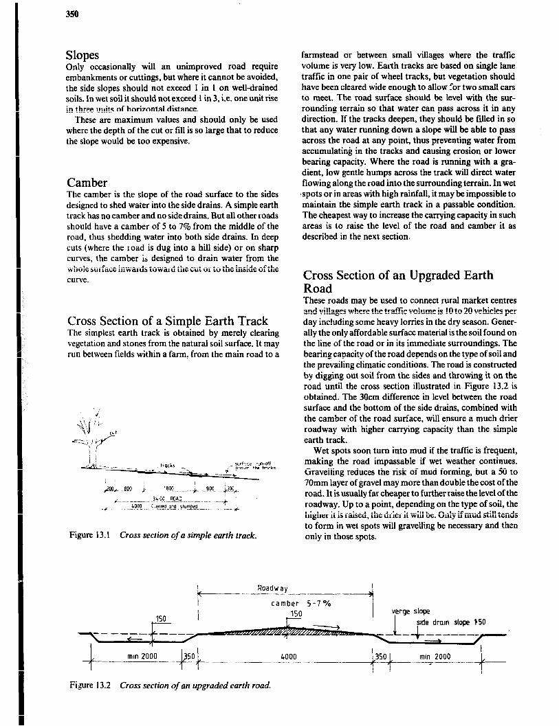
350
Slopes Only occasionally will an unimproved road require embankments or cuttings, but where it cannot be avoided, the side slopes should not exceed 1 in 1 on well-drained soils. In wet soil it should not exceed 1 in 3, i.e. one unit rise in three uuits of horizontal distance.
These are maximum values and should only be used where the depth of the cut or Ii11 is so large that to reduce the slope would be too expensive.
Camber The camber is the siope of the road surface to the sides designed to shed water into the side drains. A simple earth track has no camber and no side drains, But all other roads should have a camber of 5 to 796 from the middle of the road, thus shedding water into both side drains. In deep cuts (where the road is dug into a hill side) or on sharp curves, the camber is designed to drain water from the whole surface inwards toward the cut or to the inside of the curve.
Cross Section of a Simple Earth Track The simplest earth track is obtained by merely clearing vegetation and stones from the natural soil surface. It may run between fields within a farm. from the main road to a
Figure 13.1 Cross section of u simple earth track.
I+--- Roadway
farmstead or between small villages where the traffic volume is very low. Earth tracks are based on single lane traffic in one pair of wheel tracks, but vegetation should have been cleared wide enough to allow for two small cars to meet. The road surface should be level with the sur- rounding terrain so that water can pass across it in any direction. If the tracks deepen, they should be ftIled in so that any water running down a slope will be able to pass across the road at any point, thus preventing water from accumulating in the tracks and causing erosion or lower bearing capacity. Where the road is running with a gra- dient, low gentle humps across the track will direct water flowing along the road into the surrounding terrain. In wet spots or in areas .with high rainfall, it may be impossible to maintain the simple earth track in a passable condition. The cheapest way to increase the carrying capacity in such areas is to raise the level of the road and camber it as described in the next section.
Cross Section of an Upgraded Earth Road These roads may be used to connect rural market centres and villages where the traffic volume is 10 to 20 vehicles per day inc!uding some heavy lorries in the dry season. Gener- ally the only affordable surface material is the soil found on the line of the road or in its immediate surroundings. The bearing capacity of the road depends on the type of soil and the prevailing climatic conditions. The road is constructed by digging out soil from the sides and throwing it on the road until the cross section illustrated in Figure 13.2 is obtained. The 30cm difference in level between the road surface and the bottom of the side drains, combined with the camber of the road surface, will ensure a much drier roadway with higher carrying capacity than the simple earth track.
Wet spots soon turn into mud if the traffic is frequent, making the road impassable if wet weather continues. Gravelling reduces the risk of mud forming, but a 50 to 70mm layer of gravel may more than double the cost of the road. It is usually far cheaper to further raise the level of the roadway. Up to a point, depending on the type of soil, the higher it is raised, the drier it will be. Only if mud still tends to form in wet spots will gravelling be necessary and then only in those spots.
stde dram slope 150
i-
mm 2000 _~_-. -----
~ -?F-.. .._ .._
FQure 13.2 Cross section of an upgraded earth road.

External Facilities 35I
water from surrounding land draining onto the mad
soil dug out from drains and road surface
eroded wheel track
Figure 13.3 Road sunken due to incorrect construction and maintenance.
Erosion of Earth Roads Soil is eroded from a road by traffic, wind and water. Depending on soil conditions, climate and volume of traf- fic, soil erosion may cause considerable deterioration of the road and increase the cost of maintenance. While erosion from wind and traffic is normally of’minor importance, that caused by run-off water from heavy rains can, if uncontrolled by proper drainage and maintenance, cause deterioration, beyond what is worth repairing in only a few years.
Properly installed drainage and road maintenance go hand in hand to insure the durability and carrying capacity of an earth road. If deep tracks are allowed to form, water will accumulate in them and since most roads have at least a slight gradient, the water begins to flow. As the volume of water increases either through intensity of rainfall or inadequate side drains, its speed and eroding action will increase. Side drains, if not properly installed, will also erode.
It is obvious then that drainage of earth roads is of primary importance. It is fxential to remove rain water that falls on the road itself and to prevent that which falls on adjacent land from washing over the road. As far as possible natural drainage should be used to achieve these goals, but an engineered drainage system may be requited to adequately protect the road. Rain water that falls on the road is shed from the curved surface (camber) into shallow side drains and diverted from there through mitre drains into the bush. Where necessary, catchwater drains should be constructed which collect water flowing towards the upper side of the road allowing it to be directed across the road and back into its natural channel in a controlled way.
Side Drains When side drains are dug, care should be taken to make them shallow but wide. Water in thin layers flows slowly without causing much erosion and the grass that will grad- ually grow in the drain will further slow the flow. Gradients not steeper than 1 to 250 are unlikely to cause erosion in ordinary soils. Where steeper grades are necessary, the
drains should be emptied onto surrounding land at fre- quent intervals. Where a side drain has a very steep gra- dient, additional measures in the form of checks or gabions may be necessary. These checks will silt and form steps, thus decreasing the gradient and slowing the flow.
Figure 13.4 Scour checks willslow down the waterjlow in side drains with steep gradie.qt.
Mitre Drains Mitre drains are used along high level roads to prevent build-up of ‘war I.’ in the side drains. Depending on the gradient, mitre drains should be spaced 20 to 250m apart, using the closer intervals where rainfall is heavy, the soil is

352
prone to erosion, or the gradient is steep. The mitre drain should block off the water flow in the side drain with a bolster block at an angle of about 30 degrees and lead the water well away from the road with a wide, shallow chan- nel having a gradient of 1 in 125. The water is discharged 30 to 40m away from the road over as large an area of land as possible to prevent erosion. Figure 13.5 shows the use of mitre drains.
Figure 13.5 Mirre &ains.
Diversion Banks Simple earth roads having no side drains should have diversion banks at 30 to 250m intervals to divert water flowing along the tracks. Natural bumps in the road can
.sometimes be used as diversion banks if they can be improved to a suitable shape. These banks 30cm high and about 12m in length along the road should have a smooth contour allowing vehicles to pass easily at moderate speeds. The bank is connected to a mitre drain which feeds the water on to the adjacent land.
Catchwater Drains Where a road is constructed along the lower part of a slope or cut into a hillside, a catchwater drain will divert the excessive flow of water down the hill and across the road line. Wherever possible, it should be constructed on the upper side of and at least 3m from the edge of the road and be separate from the side drain. This construction prevents the side drain from being overloaded with water from the slope. The water in the catchwater drain must be lead off across the road line back to its natural channel in a con- trolled manner. Wherever possible a natural waterway crossing the road should be used. If a controlled lead-off cannot be easily arranged, then it is better that no catch- water drain be used since water collected by it and flowing uncontrolled across the road will cause serious erosion and form gullies.
Road Construction When the land has been surveyed and the most feasible road line has been found, the centre line of the road is set
out with pegs inserted at 15 to 20m intervals and tall enough to be clearly visible. Additional pegs may be installed to mark the width of the roadway, side drains and the area to be cleared.
Stumping and Clearing To construct a simple earth road, trees and rocks must be cleared from the road line and well back from the road so that sun and wind can dry the road surface. In heavily wooded country, trees should be cleared from the road way a distance equal to the height of the tree cover or even one and a half times that height on roads with north- south orientation. Wider clearing ensures visibility through bends and road safety in areas densely populated with wild animals.
Tree stumps can be removed by digging them out, burn- ing them or by dragging them away with draught animals or a tractor. Rocks ere either dug out and removed, buried, or broken down to ground level with a sledge hammer or by the hot-cold (fire-water) treatmeni. All holes are then tilled and compacted and any bumps leveled. Stumps and rocks should be cleared well outside the roadway since the verges are likely to br used when vehicles meet. Any stones that cannot be removed and lie beside the roadway should be clearly and permanently marked with paint or a tall white peg. The final step in constructing a simple earth track is the building of diversion banks at suitable intervals.
If the objective is to construct a high-level earth road, the work will continue with the construction of side drains.
Construction of Side Drains Using wooden pegs and string as a guideline, the edge of the road should be established 1.8 to 2.0m from the center line. On roads with no cross-fall, side drains are dug out of either side to a depth of 150mm and half the width of the roadway. All soil thus dug out is thrown on to the road and spread to form an even road surface with correct camber.
It would be advantageous to excavate the side drains in several steps, allowing some traffic to pass on the road between each step, as some unevenness of the surface can be corrected in later steps when the high and low spots become visible.
The side drains are then shaped with a gentle slope of 1: 150 away from the road. The verge and back edge of the drain are shaped with a slope of about 3: 1, thus avoiding the need for meeting bays, since vehicles can use the verge when meeting.
On sections of the road with steep cross-fall, the side drain on the upper side of the road is started at a depth of about I SOmm and then dug slightly sloping away from the road into the hill. Where the cross-fall is steeper than 1 in 30, no drain is required on the lower side of the road and the road level and camber is then formed with material only from the upper side drain.

Mitre drains should be installed without delay, espe- cially when working in wet areas. Boning rods may be used in uneven terrain to give the mitre drains an even gradient of 1 in 125. Later, on slopes where it is found necessary, catchwater drains may be installed to drain off surface water and divert it away from the road. Much of this water is often Bowing down foot paths and cattle tracks and if small diversion banks are installed on these to divert the water into the bush well away from the road, the catch- water drain may become unnecessary.
Road Maintenance The most important maintenance job on any type of earth road is to ensure that all drains work properly and that additional drains are installed wherever it becomes neces- sary. Secondly, rutted wheel tracks should be filled in with soil from outside the road bed. If the road surface becomes badly deteriorated it will be necessary to resurface the road by adding more soil from the side drains. Never remove earth from the road surface since this will lower the road level and make efficient drainage difficult or even impossi- ble. Soil should be taken from the side drains so that they are made wider rather than deeper. On cross-falls, soil should be taken only from the upper sidedrain. During the first years after construction it may be necessary to control shoots from tree roots. When vehicles start using the road, bumps (other than diversion banks) and holes will soon become apparent. These holes and any other uneveness should be repaired promptly by filling.
External Facilities 353
Minor River Crossings Where the road crosses a natural water way, a splash, drift, culvert or bridge should be built. Even if the waterway only carries water occasionally during the rainy season some kind of structure is necessary to keep the water that flows across the road from scouring and forming a gully. It is cheaper to build a splash or drift than a culvert. Bridge construction requires complex design calculations and is generally the most expensive alternative. The problem can often be simplified by choosing a road line closer to the watershed line or at an alternative crossing where condi- tions permit a splash or drift to be constructed rather than a more expensive structure.
Splashes and Drifts Splashes and drifts are the same type of construction but their sizes differ. Splashes are associated with small local run-offs whereas drifts are built where a road crosses a stream or riverbed. Splashes are frequently used where water collected by a catch-water drain is directed across the road. Information given for drifts in the following para- graphs also applies to splashes.
A drift is best suited for a crossing where the river banks are relatively low and gently sloping and the stream is shallow. Concrete is the best material for surfacing the crossing, but in many cases is too expensive. Stone and gravel are used to surface most drifts, but if the flow of water is rapid the surface may soon be eroded. In some cases grass can be planted for stabilization or the flow can be slowed by widening the water course.
Roadway ~mve\led for 15 - 30 me’res on either side at the drift LHbrizonial base as wide
as possible bit min Hmetres in a splash.
.250; 4500 - 5000 -WI j/ - 600 1 1
k 1
uaCr flow edge (size 2003COmml
top Level wilh bed of stream.
Apron -ftat stir
Figure 13.6 Sections of a splash or driji.
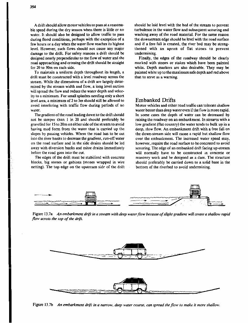
A driit should allow motor vehicles to pass at a reasona- ble speed during the dry season when there is little or no water. It should also be designed to allow traffic to pass during flood conditions, perhaps with the exception of a few hours or a day when the water flow reaches its highest level. However, such flows should not cause any major damage to the drift. For safety reasons a drift should be designed nearly perpendicular to the flow of water and the road approaching and crossing the drift should be straight for 20 to 30m on each side.
To maintain a uniform depth throughout its length, a drift must be constructed with a level roadway across the stream. While the dimensions of a drift are largely deter- mined by the stream width and flow, a long level section will spread the flow and reduce the water depth and veloc- ity to a minimum. For small splashes needing only a short level area, a minimum of 2 to 3m should still be allowed to avoid interfering with traffic flow during periods of no water.
The gradient of the road leading down to the drift should not be steeper than 1 in 20 and should preferably be gravelled for 15 to 20m on either side of the stream to avoid having mud form from the water that is carried up the slopes by passing vehicles. Where the road has to be cut into the river banks to decrease the gradient, run-off water on the road surface and in the side drains should be led away with diversion banks and mitre drains immediately before the road goes into the cut.
The edges of the drift must be stabilized with concrete blocks, big stones or gabions (stones wrapped in wire netting). The top edge on the upstream side of the drift
--
should be laid level with the bed of the stream to prevent turbulence in the water flow and subsequent scouring and washing away of the road material. For the same reason the downstream edge should be level with the road surface and if a free fall is created, the river bed may be streng- thened with an apron of flat stones to prevent undermining.
Finally, the edges of the roadway should be clearly marked with stones or stakes which have been painted white. Depth markers are also desirable. They may be painted white up to the maximum safe depth and red above that to serve as a warning.
Embanked Drifts Motor vehicles and other road traffic can tolerate shallow water better than deep water even if the flow is more rapid. In some cases the depth of water can be decreased by raising the roadway on an embankment. In streams with a low gradient (flat country) the water tends to bulk up in a deep, slow flow. An embankment drift with a free fall on the down-stream side will cause a rapid but shallow flow over the embankment. The increased water speed may, however, require the road surface to be concreted to avoid scouring. The edge of an embanked drift facing up-stream will normally have to be constructed m concrete or masonry work and be designed as a dam. The structure should preferably be carried down to a solid base in the bottom of the riverbed to avoid undermining.
Figure 13.7a An embarkment drqt in a stream with deep water flow because of slight gradient will create a shallow rapid flow across the top of the drif
Figure 13.7b An embarkment drif in a narrow, deep water course, can spread theflow to make it more shallow.
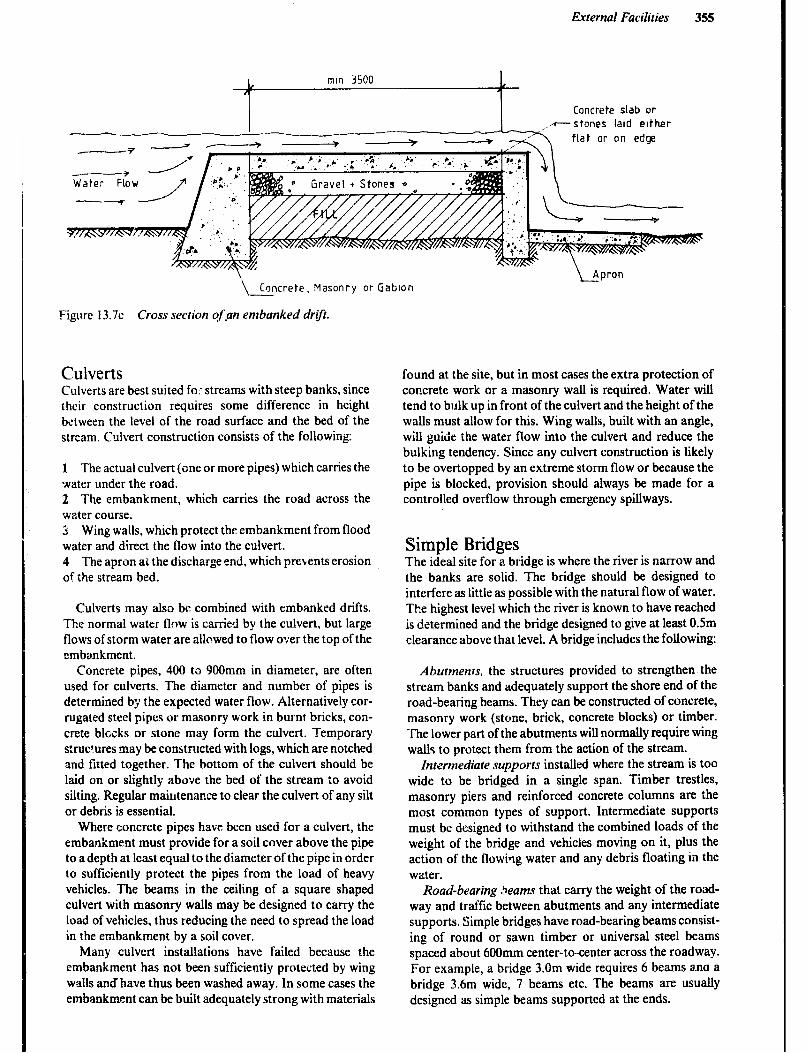
External Facilities 355
Concrete slab or stones laid either
flat or on edge
\&ncrete. Masonry or Gabton
Figure 13.7~ Cross section of pn embanked drift.
Culverts Culverts are best suited for streams with steep banks, since their construction requires some difference in height between the level of the road surface and the bed of the stream. Culvert construction consists of the following:
1 The actual culvert (one or more pipes) which carries the water under the road. 2 The embankment, which carries the road across the wzter course. 3 Wing walls, which protect the embankment from flood water and direct the flow into the culvert. 4 The apron a& the discharge end. which prevents erosion of the stream bed.
Culverts may also be combined with embanked driits. The normal water flow is carried by the culvert, but large flows of storm water are allowed to flow over the top of the emba.nkment.
Concrete pipes, 400 tc 900mm in diameter, are often used for culverts. The diameter and number of pipes is determined b;r the expected water flow. Alternatively cor- rugated steel pipes or masonry work in burnt bricks, con- crete blocks or stone may form the culvert. Temporary s:ruc?ures may be constructed with logs, which are notched and fitted together. The bottom of the culvert should be laid on or slightly above the bed of the stream Co avoid silting. Regular maintenance to clear the culvert of any silt or debris is essential.
Where concrete pipes have been used for a culvert, the embankment must provide for a soil cover above the pipe to a depth at least equal to the diameter of the pipe in order to sufficiently protect the pipes from the load of heavy vehicles. The beams in the ceiling of a square shaped culvert with masonry walls may be designed to carry the load of vehicles, thus reducing the need to spread the load in the embankment by a soil cover.
Many culvert installations have failed because the embankment has not been sufficiently protected by wing walls andhave thus been washed away. In some cases the embankment can be built adequately strong with materials
found at the site, but in most cases the extra protection of concrete work or a masonry wall is required. Water will tend to bulk up in front of the culvert and the height of the walls must allow for this. Wing walls, built with an angle, will guide the water flow into the culvert and reduce the bulking tendency. Since any culvert construction is likely to be overtopped by an extreme storm flow or because the pipe is blocked, provision should always be made for a controlled overflow through emergency spillways.
Simple Bridges The ideal site for a bridge is where the river is narrow and the banks are solid. The bridge should be designed to interfere as little as possible with the natural flow of water. The highest level which the river is known to have reached is determined and the bridge designed to give at least 0.5m clearance above that level. A bridge includes the following:
Abutments, the structures provided to strengthen the stream banks and adequately support the shore end of the road-bearing beams. They can be constructed of concrete, masonry work (stone, brick, concrete blocks) or timber. The lower part of the abutments will normally require wing walls to protect them from the action of the stream.
Intermediate supports installed where the stream is too wide to be bridged in a single span. Timber trestles, masonry piers and reinforced concrete columns are the most common types of support. Intermediate supports must be designed to withstand the combined loads of the weight of the bridge and vehicles moving on it, plus the action of the flowing water and any debris floating in the water.
Road-bearing 3eams that carry the weight of the road- way and traffic between abutments and any intermediate supports. Simple bridges have road-bearing beams consist- ing of round or sawn timber or universal steel beams spaced about 600mm center-to-center across the roadway. For example, a bridge 3.0m wide requires 6 beams ana a bridge 3.6m wide, 7 beams etc. The beams are usually designed as simple beams supported at the ends.

356
,_ ,. I’.~,
,.
PERSPECTIVE VIEti
ness 1s one ptp
SECTION
Figure 13.8 Culvert.
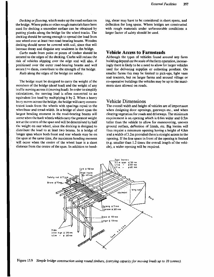
External Facilities 357
Decking orflooring, which make up the road surface on the bridge. Where poles or other rough materia1.s have been used for decking a smoother surface can be obtained by putting planks along the bridge for the wheel tracks. The decking should be strong enough to spread the load from one wheel over at least two road-bearing beams. Wooden decking should never be covered with soil, since that will increase decay and disguise any weakness in the bridge.
Curbs made from poles or pieces of timber should be secured to the edges of the decking. Curbs will reduce the risk of vehicles slipping over the edge and will also, if positioned over the outer road-bearing beams and well secured to them, contribute to the strength of the bridge.
Rails along the edges of the bridge ibr safety.
The bridge must be designed to carry the weight of the members of the bridge (dead load) and the weight of any traffic moving across it (moving load). In order to simplify calculations, the moving load is often converted to an equivalent live load by multiplying it by 2. When a heavy lorry moves across the bridge, the bridge will carry concen- trated loads from the wheels with spacings equal to the wheelbase and tread-width. In a bridge of short span the largest bending moment in the road-bearing beams will occur when the back wheels which carry the greatest weight are at the centre of the span and will be determined by half the weight on one wheel, since the decking is designed to distribute the load to at !east two beams. In a bridge of longer span where both front and rear wheels may be on the span at the same time, the maximum bending moment will occur when the centre of the wheel base is a short distance from the centre of the span. In addition to bend-
ing, shear may have to be considered in short spans, and deflection for long spans. Where bridges are constructed with rough materials under unfavourable conditions a larger factor of safety should be used.
Vehicle Access to Farmsteads Although the types of vehicles found around any farm building depend on the scale of the farm operation, increas- ingly there is likely to be a need to allow for larger vehicles used for delivering supplies or collecting produce. On smaller farms this may be limited to pick-ups, light vans and tractors, but on larger farms and around village or co-operative buildings the vehicles may be up to the maxi- mum sizes allowed on roads.
Vehicle Dimensions The overall width and height of vehicles are of importance when designing door openings, gateways etc., and when clearing vegetation for roads and driveways. The minimum requirement is an opening which is 0.6m wider and 0.5m taller than the vehicle to allow for maneuvering, uneven ground surface, deflection of lintels, etc. Big lorries will thus require a minimum opening having a height of 4.8m and a width of 3.2m provided there is straight access to the opening. If the free space in front of the opening is limited (e.g. smaller than 1.2 times the overall length of the vehi- cle), a wider opening will be required.
Road bearers
m
3 0 m span )ZPD mm ( 45 m - fJ300 mm
4 300 mm
Brace b 100mm ‘.
Figure 13.9 Simple bridge construction using round timbers, (carrying capacity for moving loach up to 10 tonnes).
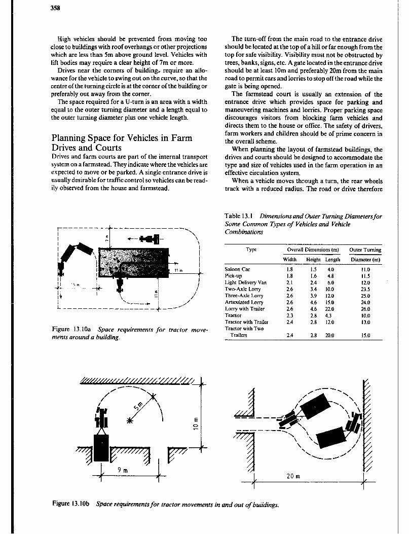
358
High vehicles should be prevented from moving too close to buildings with roof overhangs or other projections which are less than Sm above ground level. Vehicles with lift bodies may require a clear height of 7m or more.
Drives near the corners of buildin& require an allo- wance for the vehicle to swing out on the curve, so that the centre of the turning circle is at the corner of the building or preferably out away from the corner.
The space required for a U-turn is an area with a width equal to the outer turning diameter and a length equal to the outer turning diameter plus one vehicle length.
Planning Space for Vehicles in Farm Drives and Courts Drives and farm courts are part of the internal transport system on a farmstead. They indicate where the vehicles are expected to move or be parked. A single entrance drive is usually desirable for trafticcontrol so vehicles can be read- ily observed from the house and farmstead.
Figure 13.1Oa Space requirements for tractor move- ments around a building.
The turn-off from the main road to the entrance drive should be located at the top of a hill or far enough from the top for safe visibility. Visibility must not be obstructed by trees, banks, signs, etc. A gate located in the entrance drive should be at least 10m and preferably 20m from the main road to permit cars and lorries to stop off the road while the gate is being opened.
The farmstead court is usually an extension of the entrance drive which provides space for parking and maneuvering machines and lorries. Proper parking space discourages visitors from blocking farm vehicles and directs them to the house or office. The safety of drivers, farm workers and children should be of prime concern in the overall scheme.
When planning the layout of farmstead buildings, the drives and courts should be designed to accommodate the type and size of vehicles used in the farm operation in an effective circulation system,
When a vehicle moves through a turn, the rear wheels track with a reduced radius. The road or drive therefore
Table 13.1 Dimensions and Outer Turning Diametersfor Some Common i’)pes of Vehicles and Vehicle Combinations
Tw Overall Dimensions (m) Outer Turning
Saloon Car Pick-uo Light Delivery Van Two-Axle Lorry Three-Axle Lorry Articulated Lorry Lorry with Trailer Tractor Tractor with Trailer Tractor with Two
Trailers
Width Height Length
1.8 1.5 4.0 1.8 I.b 4.8 2.1 2.4 6.0 2.6 3.4 10.0 2.6 3.9 12.0 2.6 4.6 I5.0 2.6 4.6 22.0 2.3 2.8 4.3 2.4 2.8 12.0
2.4 2.8 20.0 15.0
Diameter(m)
11.0 II.5 12.0 23.5 25.0 24.0 26.0 10.0 13.0
Figure 13.10b Space requirements for tractor movements in and out of buildings.

External Facilities 359
needs to be wider at curves. Articulated vehicles may almost pivot around the centre of the turning circle in a sharp turn or U-turn.
Gravelling of the most frequently used areas will improve the drainage and keep the surface of the drives firm and durable throughout the year. Extra parking space for storage of machines and supplies can be stabilized by sodding.
Heavy vehicle traffic close to retaining walls, tanks and similar structures should be barred within a distance equal to or greater than the height of the wall or structure.
Greater thm H
Figure 13. I I Protect retaining walls from heavily loaded vehicles causing shearing of soil.
Fencing The two maia objectives of fencing on a farm are security and improved livestock management, but fences may also be used as wind breaks, to provide privacy and to improve appearance. The type of fence chosen for a specific situa- tion will be determined by the objective or the combination of objectives for which it is built.
security Fencing is often used to protect property and growing crops from theft and damage by people or animals. Where the objective is solely the demarcation of boundaries very simple structures may be sufficient. On the other hand, fences, which are designed to stop intruders from entering, must be high, dense, sturdy and be topped with spikes or barbs. As secure fences can be quite expensive, their use is limited to enclosing particularly valuable property. The three most widely used types of fences for this purpose are:
1 Round or square vertical bars of wood or steel secured to horizontal rails and fixed to posts set 2 to 3m apart. These are very difficult to climb. 2 Chain link (diamond mesh) netting, about 2m high and fixed to posts set 3m apart. In both types, stays may be used for extra strength and a barbed wire top added for extra szcurity. 3 Thorny hedges.
Fencing is also used for protection around ponds, along steep slopes or in other hazardous locations.
Improved Livestock Management Herding has been the traditional method of controlling livestock movements during grazing. Fencing was only done to exclude the animals from certain areas such as homesteads and cultivated fields and to safeguard them at night.
With “extensive” livestock production, fencing is likely to be so costly that herding must continue to be practiced. However, it is not uncommon to enclose the land with a boundary fence. With ?ntensive”livestock production, it is often feasible to subdivide the land. The greater number of paddocks allows for flexibility in stocking and division of the livestock into different classes or age groups. It is seldom economical to subdivide the land beyond what is necessary for efli&.nt grazing practice.
In Africa some of the worst livestock diseases are tick- borne and fencing can play an important roll in breaking the disease cyc!r: by maintaining a disease-free condition once enough ticks have been eradicated by spraying or dipping the livestock regularly. Fencing also helps to limit the spread of other infectious diseases and to reduce prob- lems wi:h parasites. Fencing will also prevent improved animals from being bred by animals from outside the farm.
In intensive dairy production the animals are often grouped according to production to allow for more effi- cient feeding of concentrates and for improved manage- ment practices. The various groups of animals are kept separate by fences and other structures, such as feed racks.
Types of Fences Any type of structure which forms an effective barrier to livestock movements or which restricts human movements can be termed a fence. The following types are the most common on farms.
Wire Fences such as: l Plain wire fences. 0 Barbed wire fences. l Suspension fences. 0 Wire netting fences. 0 Electric fences.
Other Types of Fences such as: 0 Post and Rail Fences. 0 Hedges. 0 Log fences. l Walls.
Wire Fences
Types of Wire Plain or barbed-wire fences are best suited for fencing of large areas. Plain wire is cheaper than barbed wire, but requires a higher standard of assembly and of construction for posts since the wires must be permanently strained to be
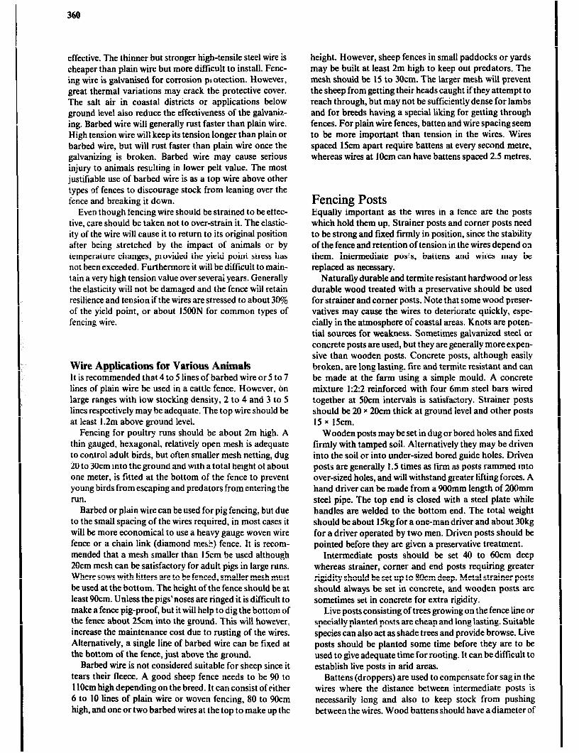
effective. The thinner but stronger high-tensile steel wire is cheaper than plain wire but more difficult to install. Fenc- ing wire is galvanised for corrosion plotection. However, great thermal variations may crack the protective cover. The salt air in coastal districts or applications below ground level also reduce the effectiveness of the galvaniz- ing. Barbed wire will generally rust faster than plain wire. High tension wire will keep its tension longer than plain or barbed wire, but will rust faster than plain wire once the galvanizing is broken. Barbed wire may cause serious injury to animals resulting in lower pelt value. The most justifiable use of barbed wire is as a top wire above other types of fences to discourage stock from leaning over the fence and breaking it down.
Even though fencing wire should be strained to be effec- tive, care should be taken not to over-strain it. The elastic- ity of the wire will cause it to return to its original position after being stretched by the impact of animals or by temperature changes, provided the yield point stress has not been exceeded. Furthermore it will be difficult to main- tain a very high tension value over severai years. Generally the elasticity will not be damaged and the fence will retain resilience and tension if the wires are stressed to about 30% of the yield point, or about 15OON for common types of fencing wire.
Wire Applications for Various Animals It is recommended that 4 to 5 lines of barbed wire or 5 to 7 lines of plain wire be used in a cattle fence. However, on large ranges with low stocking density, 2 to 4 and 3 to 5 lines respectively may be adequate. The top wire should be at least 1.2m above ground level.
Fencing for poultry runs should be about 2m high. A thin gauged, hexagonal, relatively open mesh is adequate to control adult birds, but often smaller mesh netting, dug 20 to 30cm into the ground and with a total height of about one meter, is fitted at the bottom of the fence to prevent young birds from escaping and predators from entering the run.
Barbed or plain wire can be used for pig fencing, but due to the small spacing of the wires required, in most cases it will be more economical to use a heavy gauge woven wire fence or a chain link (diamond mesh) fence. It is recom- mended that a mesh smaller than 15cm be used although 20cm mesh can be satisfactory for adult pigs in large runs. Where sows with litters are to be fenced, smaller mesh must be used at the bottom. The height of the fence should be at least 9Ocm. Unless the pigs’noses are ringed it is difficult to make a fence pig-proof, but it will help to dig the bottom of the fence about 25cm into the ground. This will however, increase the maintenance cost due to rusting of the wires. Alternatively, a single line of barbed wire can be fixed at the bottom of the fence, just above the ground.
Barbed wire is not considered suitable for sheep since it tears their fleece. A good sheep fence needs to be 90 to 1lOcm high depending on the breed. It can consist of either 6 to 10 lines of plain wire or woven fencing, 80 to 9Ocm high, and one or two barbed wires at the top to make up the
height. However, sheep fences in small paddocks or yards may be built at least 2m high to keep out predators. The mesh should be 15 to 30cm. The larger mesh will prevent the sheep from getting their heads caught if they attempt to reach through, but may not be sufficiently dense for lambs and for breeds having a special liking for getting through fences. For plain wire fences, batten and wire spacing seem to be more important than tension in the wires. Wires spaced 15cm apart require battens at every second metre, whereas wires at 1Ocm can have battens spaced 2.5 metres.
Fencing Posts Equally important as the wires in a fence are the posts which hold them up. Strainer posts and corner posts need to be strong and fmed firmly in position, since the stability of the fence and retention of tension in the wires depend on them. Intermediate posts, battens and wires may be replaced as necessary.
Naturally durable and termite resistant hardwood or less durable wood treated with a preservative should be used for strainer and comer posts. Note that some wood preser- vatives may cause the wires to deteriorate quickly, espe- cially in the atmosphere of coastal areas. Knots are poten- tial sources for weakness. Sometimes galvanized steel or concrete posts are used, but they are generally more expen- sive than wooden posts. Concrete posts, although easily broken, are long lasting, fire and termite resistant and can be made at the farm using a simple mould. A concrete mixture 1:2:2 reinforced with four 6mm steel bars wired together at 5Ocm intervals is satisfactory. Strainer posts should be 20 x 20cm thick at ground level and other posts 15 x 15cm.
Wooden posts may be set in dug or bored holes and fixed firmly with tamped soil. Alternatively they may be driven into the soil or into under-sized bored guide holes. Driven posts are generally 1.5 times as firm as posts rammed into over-sized holes, and will withstand greater lifting forces. A hand driver can be made from a 900mm length of 200mm steel pipe. The top end is closed with a steel plate while handles are welded to the bottom end. The total weight should be about 15kg for a one-man driver and about 30kg for a driver operated by two men. Driven posts should be pointed before they arc given a preservative treatment.
Intermediate posts should be set 40 to 6Ocm deep whereas strainer, corner and end posts requiring greater rigidity should be set up to 80cm deep. Metal strainer posts should always be set in concrete, and wooden posts are sometimes set in concrete for extra rigidity.
Live posts consisting of trees growing on the fence line or specially planted posts are cheap and long lasting. Suitable species can also act as shade trees and provide browse. Live posts should be planted some time before they are to be used to give adequate time for rooting. It can be difficult to establish live posts in arid areas.
Battens (droppers) are used to compensate for sag in the wires where the distance between intermediate posts is necessarily long and also to keep stock from pushing between the wires. Wood battens should have a diameter of

External Facilities 361
25 to 40mm and will last longer if treated with a preserva- tive. Alternatively, wire lashings may be used to maintain the distance between the wires or extra wires can be supp- lied to decrease the spacing, thus reducing the need for battens.
Stapling is the most common method of fixing the wires to the posts. Alternatively they may be secured with 2mm galvanized mild steel ties. However, it is difficult to make such a tie secure against sliding on the post. When stapling, the wire should be loosely stapled to the intermediate posts. Staples driven too far will bend and hammer out the wire, thus creating a weak spot. Splitting of the posts can be lessened if the staples are driven diagonally into the grain.
AI il. -2
t
Figure 13.12b Single horizontal sray.
Wire Fence Construction The length of fencing required per hectare will vary greatly with the form and size of the fields. Square fields have the lowest fencing cost per unit area, and the larger the fields the lower the fencing length per hectare. Fence lines should be as long, straight and unbroken as possible, since corner posts and gate posts require bracing and thus add to the cost.
When the fence line has been laid out, the ground area over which the wires will be stretched should be cleared. Next the strainer assemblies are installed. These will take the whole strain of the stretching of the wires and it is therefore most important that they are firmly set and well- braced. Normally strainer assemblies are located next to comer and gate posts, but on long straight stretches of fence, additional strainers should be installed at up to 200m intervals if the ground is even, or at the top and bottom of each slope in hilly terrain.
Three types of strainer assemblies in general use are shown in Figure 13.12a, b and c. The double horizontal- stay strainer assembly is extremely rigid in all types of soil, but for most purposes the single horizontal-stay assembly will be sufficient. On firm but easily dug soil the traditional assembly with a diagonal stay will be adequate and the cheapest in terms of material.
Corner posts should have a diameter of at least 150mm and be braced in the direction of both fencing lines. Corner posts, where the fence angle is less than 45’, will be suffi- ciently rigid if braced with a single diagonal stay or diago- nal tie-back.
Figure 13.12a Double horizontal stay.
Figure 13.12~ Traditional strainer with diagonal stay.
Figure 13.12 i%ree types of strainer assemblies.
Intermediate posts having a diameter of 75 to 125mm should be set exactly in line to avoid any horizontal forces due to strain in the wires. Where there is a pronounced low spot in the fence line, one or two of the intermediate posts in the low area may require extra security against uplift by being driven deeper or set in concrete. For a plain-wire catt!e fence no battens are required if the intermediate posts are spaced no more than 3.5 to 5m, but the posts can be set up to 15m apart if battens are used at 3.5 to 4m intervals. Woven wire fence requires intermediate posts every 4 to 5m and chicken wire every 2m.
The wire or wire netting is then attached to the posts. Starting with the bottom wire, it is first secured to a strainer post, then stretched using a tackle-block stretcher, chain- type stretcher or, for single plain or barbed wires, a simple wooden lever. When the wire has been stretched tight enough it is secured to the next strainer post by wrapping and stapling. The wire should be on the inside of all posts, and taken one turn around any corner post. After the fence-stretcher has been released the wires are loosely fas- tened to the intermediate posts and finally battens are fixed as necessary.
When the fence is erected all bits of wire, nails and staples should be collected to avoid “hardware disease” caused by the animals eating the scrap metal.
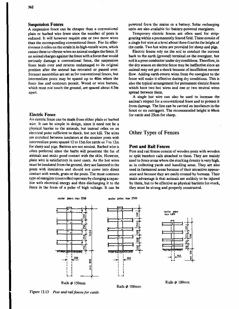
362
Suspension Fences A suspension fence can be cheaper than a conventional plain or barbed wire fence since the number of posts is reduced. It will however require one or two more wires than the corresponding conventional fence. For its effec- tiveness it relies on the strain in its high-tensile wires, which causes them to vibrate when an animal nudges the fence. If an animal charges against the fence with a force that would seriously damage a conventional fence, the suspension fence heals over and returns undamaged to its original position after the animal has retreated or passed over. Strainer assemblies are set as for conventional fences, but intermediate posts may be spaced up to 40m where the fence line and contours permit. Wood or wire battens, which must not touch the ground, are spaced about 4.5m apart.
Electric Fence An electric fence can be made from either plain or barbed wire. It can be simple in design, since it need not be a physical barrier to the animals, but instead relies on an electrical pulse sufficient to shock, but not kill. The wires are stretched between insulators at the strainer posts with intermediate posts spaced 12 to 15m for cattle or 7 to 12m for sheep and pigs. Battens are not needed. Barbed wire is often preferred since the barbs wiLl penetrate the fur of animals and make good contact with the skin. However, plain wire is satisfactory in most cases. As the hot wires must be insulated from the ground. they are fastened to the posts with insulators and should not come into direct contact with weeds, grass or the posts. The most common type of energizer (controller) operates by charging acapac- itor with electrical energy and then discharging it to the fence in the form of a pulse of high voltage. It can be
center paler max 2500
powered from the mains or a battery. Solar recharging units are also available for battery-powered energizers.
Temporary electric fences are often used for sttip- grazing within a permanently fenced field. These consist of a single ho: wire at a level about three-fourths the height of the cattle. Two hot wires are provided for sheep and pigs.
Electric fences rely on the soil to conduct the current back to the earth (ground) terminal on the energizer, but soil is a poor conductor under dry conditions. Therefore, in the dry season an electric fence may be ineffective since an animal may not get a shock because of insufficient current flow. Adding earth-return wires from the energizer to the fence will make it effective during dry conditions. This is also the typical arrangement for permanent electric fences which have two hot wires and one or two neutral wires spread between them.
A single hot wire can also be used to increase the animal’s respect for a conventional fence and to protect it from damage. The line can be carried on insulators in the fence or on outriggers. The recommended height is 6Ocm for cattle and 25cm for sheep.
Other Types of Fences
Post and Rail Fences Post and rail fences consist of wooden posts with wooden or sptit bamboo rails attached to them. They are mainly used to fence areas where the stocking density is very high, as in collecting yards and handling areas. They are also used in farmstead areas because of their attractive appear- ance and because they are easily crossed by humans. Their main advantage is that animals are unlikely to be injured by them, but to be effective as physical barriers for stock, they must be strong and properly constructed.
center poles max 2500
Rails @ 150mm
Figure 13.13 Post and railfences for cattle.
Rails @ IOOmm Rails $I 1OOmm
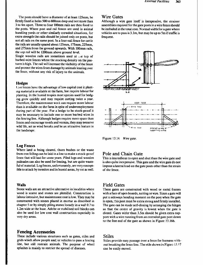
External Facilities 363
The posts should have a diameter of at least i 25mm, be firmly fixed in holes 500 to 8OOmm deep and not more than 3 to 4m apart. Three to four 1OOmm raiis are then fixed to the posts. Where post and rail fences are used in animal handling yards or other similarly crowded situations, for extra strength the rails should be joined only on posts, but not all rails on the same post. In a four-rail fence for cattle the rails are usually spaced about 125mm, 175mm, 225mm, and 275mm from the ground upwards. With IOOmm rails, the top rail will be 12OOmm above ground level. Single wooden rails are sometimes used at ;,le top of barbed-wire fences where the stocking density on the pas- tures is high. The rail wi!l increase the visibility of the fence and protect the wires from damage by animals leaning over the fence, without any risk of injury to the animals.
Hedges Live fences have the advantage of low capital cost itplant- mg material is available at the farm, but require labour for planting. In the humid tropics most species used for hedg- ing grow quickly and may require cutting twice a year. Therefore, the maintenance WOI k can require more labour than is available on the farm in spite of underemployment during part of the year. For a hedge to be stock-proof it may be necessary to include one or more barbed wires in the fencing line. Although hedges require more space than fences and encourage weeds and vermin, they may preserve wild life, act as wind breaks and be an attractive feature in the landscape.
Wire Gates Although a wire gate itself is inexpensive, the strainer assemblies required for the gate posts in a wire fence should be included in the total cost. Normal width for a gate where vehicles are to pass is 3.3m, but may be up to 5m iftraffic is frequent.
Figure I3.14 Wire gate.
Log Fenct% Where land is being cleared, thorn bushes or the waste from tree felling can be laid in a line to make a stock-proof fence that will last for some years. Piled logs and wooden palisades can also be used for fencing, but are quite waste- ful of material. Log fences, unfortunately, are very suscept- ible to attack by termites and in humid areas, by roi as well.
Pole and Chain Gate This is less tedious to open and shut than the wire gate and is also quite inexpensive. This gate and the wire gate do not impose a lateral load on the gate posts other than the strain of the fence.
Walls Stone walls are an attractive alternative in localities where wood is scarce and stones are plentiful. Construction is labour intensive. but maintenance cost is low. They may be constructed with stones placed in mortar as described in chapter 5 or by simply piling stones loosely in a wal: 0.7 to 1.2m wide at the base. Adobe or stabilised soil blocks can also be used for low cost wall construction especially in very dry areas.
Field Gates These gates are constructed with wood or metal frames with a face of open boards, netting or wire. Since a gate will put a sideways bending moment on the post when the gate is open, this post must be extra strong and firmly installed. The gate can be made self-closing by arranging the hinges so that the centre of gravity is lowest when the gate is closed. Gates wider than 3.5m should be given extra sup- port with a wire running from an extended gate post down to the free end of the gate as shown in Figure 13.16b.
Fencing Accessories These include various structures such as gates, stiles and grids which allow people and/ or vehicles to pass a fencing line, but still restrain animals. The purpose of wheel splashes is mainly to restrict the spread of diseases.
Stiles Stiles provide easy passage over a fence for humans with- out breaking the fence line. The stile shown in Figure I?. ! 7 can be easily moved.
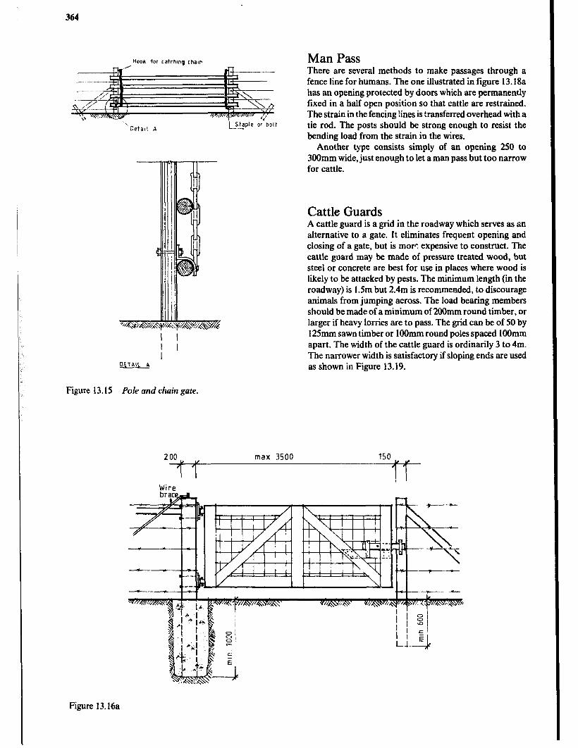
364
Hook for tatchms chain Man Pass There are several methods to make passages through a fence line for humans. The one illustrated in figure 13.18a has an opening protected by doors which are permanently fixed in a half open position so that cattle are restrained. The strain in the fencing lines is transferred overhead with a tie rod. The posts should be strong enough to resist the bending load from the strain in the wires.
Another type consists simply of an opening 250 to 3OOmm wide, just enough to let a man pass but too narrow for cattle.
Cattle Guards A cattle guard is a grid in the roadway which serves as an alternative to a gate. It eliminates frequent opening and closing of a gate, but is more expensive to construct. The cattle guard may be made of pressure treated wood, but steel or concrete are best for use in places where wood is likely to be attacked by pests. The minimum length (in the roadway) is 1.5m but 2.4m is recommended, to discourage animals from jumping across. The load bearing members should be made of a minimum of 2OOmm round timber, or larger if heavy lorries are to pass. The grid can be of 50 by 125mm sawn timber or 1OOmm round poles spaced 1OOmm apart. The width of the cattle guard is ordinarily 3 to 4m. The narrower width is satisfactory if sloping ends are used as shown in Figure 13.19.
Figure 13.15 Pole and chain gate.
200 max. 3500 150
3-T
Wire
Figure 13.16a

External Facilities 365
,
-
Figure I3.16b
Figure 13.16 Two types ofj?eld gate.
35Of'- 6COO ---- - -.--- .-.----- 1
d5”
Block to support
end of gate
Figure 1.1. I7 Stile. Figure 13.18a
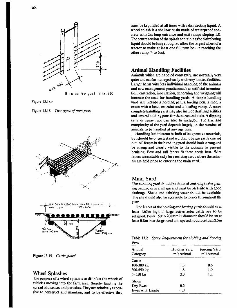
366
If no centre post max.300
Figure 13.18b
Figure 13.18 fi)o types of man puss.
Clrd SC*125sawn tlmbtr,mtn 100 6 poles
l- or
metal plpez --_---.
lSOC- 2LDO
t
Figure 13.19 Cuttleguurd.
Wheel Splashes The purpose of a wheel splash is to disinfect the wheels of vehicles moving into the farm area, thereby limiting the spread of diseases and parasites. They are relatively expen- sivc to construct and maintain, and to be effective they
must be kept filled at all times with a disinfecting liquid. A wheel splash is a shallow basin made of waterproof con- crete with 2m long entrance and exit ramps sloping I:& The centre section of the splash containing the disinfecting liquid should be long enough to allow the largest wheel of a tractor to make at least one full turn be ’ :e reaching the other ramp (4 to 6m).
Animal Handling Facilities Animals which are handled constantly, are normally very quiet and can be managed easily with very limited facilities. Larger herds with less individual handling of the animals and new management practices such as artificial insemina- tion, castration, inoculation, dehorning and weighing will increase the need for handling yards. A simple handling yard will include a holding pen, a forcing pen, a race, a crush with a head restraint and a loading ramp. A more complete handling yard may also include drafting facilities and several holding pens for the sorted animals. A dipping tz?k or spray race can also be included. The size and complexity of the yard depends largely on the number of animals to be handled at any one time.
Handling facilities can be built of inexpensive materials, but should be of such standard that jobs are easily carried out. All fences in the handling yard should look strong and be strong and clearly visible to the animals to prevent bruising. Post and rail fences fit these needs best. Wine fences are suitable only for receiving yards where the anim- als are held prior to entering the main yard.
Main Yard The handling yard should be situated centrally to the graz- ing paddocks in a village and must be on a site with good drainage. Shade and drinking water should be available. The site should also be accessible to lorries throughout the year.
The fences of the holding and forcing yards should be at least 1.65m high if large active zebu cattle are to be retained. Posts 150 to 200mm in diameter should be set at least 0.8m into the ground and spaced not more than 2.5m
Table 13.2 Space Requirement for Voiding and Forcing Pens
Animal Holding Yard Category m2/ Animal
Forcing Yard In21 Animal
Cattle 100-300 kg 300-550 kg >550 kg
Sheep Dry Ewes Ewes with Lambs
1.3 0.6 1.6 1.0 2.0 1.2
03 .I.0

External Facilities 361
apart. Four 150mm or five 1OOmm rails are attached to the inside of the po;+s with slightly larger spacing at the top of the fence.
Holding yards for sheep can have lower fences, but they need smaller rail spacing, especially if lambs are to be handled.
I/ 1 15m 1
I
., hanway 025 m wide
_ Race
,,slidlng gate or bar
HOLDING YARD --crush
c
entrance
Figure 13.20 Simple cattle yard.
E
E
Cattle Races and Crushes Quick operations such as branding, spraying and giving injections only need a race to position the cattle. More specialised work such as ear marking, dehorning, castra- tion, foot trimming, weighing, artificial insemination, pregnancy testing and veterinary operations requires a crush to firmly restrain an animal. The crush is best located as an extensicn of the race. Moving cattle into the race is often a slow process, but once a few animals have entered, others will readily follow. The race should therefore be long enough to hold three animals waiting to enter the crush or be at least 6m long. Post and rail fences of the same type as for the holding yard are used for the race, but the height should be increased to 1.8m. Where round timbers are used for rails, they should be arranged so that the thick end of the pole faces the front of the race to minimize the risk of animals injuring themselves on pro- jecting butt-ends. The rails should be joined on posts for extra strength. It is important that the width of the race be correct so that animals car move easily but cannot turn around, i.e. 500 to 700mm between rails depending on the size of the cattle. Cattle with very large horns are a problem.
The only real answer is to build a race with sloping sides and reduce the height of the fence.
It is desirable for the entire length of the race and crush to be floored wizh concrete. A solid wall about 600mm high at the bottom of Lie fences will reduce the risk of leg injury if the cattle should .lip. Such walls are especially necessary in races with slo; :ng sides.
A simple crush ntr 1 only consist of a head bail at the end of the race and a side opening gate in the last panel of the race. To improve access to the side of the animal, the gate can be split horizontally in halves so that the top half can be optaed while the bottom haif restrains the animal. It will also be advantageous to have a sliding gate or tail bar at the entrance of the crush to hold back animals and give easier access to the rear of the animal in the crush. The animals should not have to back up to leave the crush. This can be
Figure 13.2 1 Alternative sections for cattle race.
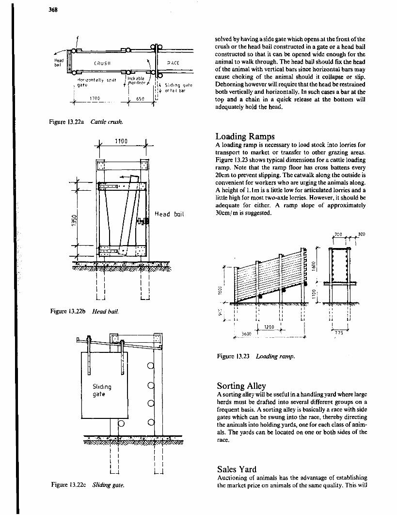
368
Head bad
ortall bar
Figure 13.22a Curtic crush.
/ 1100 , I I
Figure 13.22b Head bail.
Figure 13.22~ Sliding gate.
solved by having a side gate which opens at the front of the crush or the head bail constructed in a gate or a head bail constructed so that it can be opened wide enough for the animal to walk through. The head bail should fix the head of the animal with vertical bars since horizontal bars may cause choking of the animal should it collapse or slip. Dehorning however will require that the head be restrained both vertically and horizontally. In such cases a bar at the top and a chain in a quick release at the bottom will adequately hold the head.
Loading Ramps A loading ramp is necessary to load stock into lorries for transport to market or transfer to other grazing areas. Figure 13.23 shows typical dimensions for a cattle loading ramp. Note that the ramp floor has cross battens every 20cm to prevent slipping. The catwalk along the outside is convenient for workers who are urging the animals along. A height of 1.1 m is a little low for articulated lorries and a little high for most two-axle lorries. However, it should be adequate for either. A ramp slope of approximately 30cmj m is suggested.
Figure 13.23 Loading ramp.
Sorting Alley A sorting>llejr wiil be useful in a handling yard where large herds must be drafted into several different groups on a frequent basis. A sorting alley is basically a race with side gates which can be swung into the race, thereby directing the animals into holding yards, one for each class of anim- als. The yards can be located on one or both sides of the race.
Sales Yard Auctioning of animals has the advantage of establishing the market price on animals of the same quality. This will
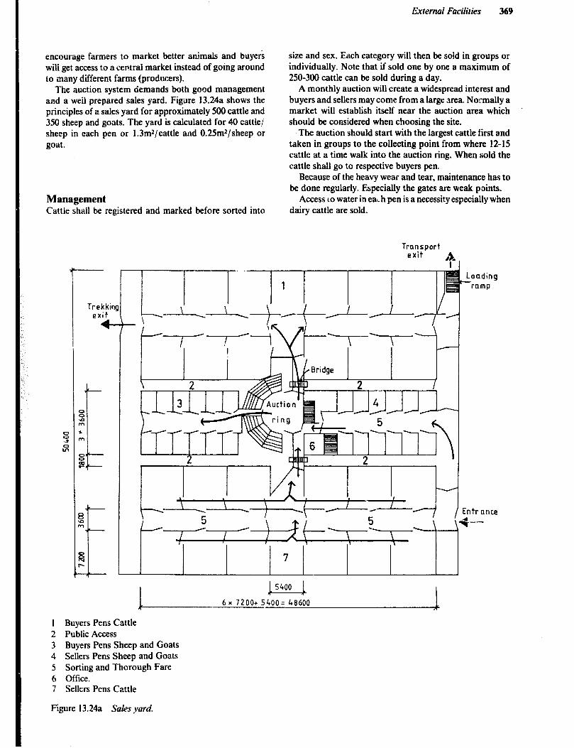
External Facilities 369
encourage farmers to market better animals and buyers wili get access to a central market instead of going around to sany different farms (producers).
The auction system demands both good management and a weil prepared sales yard. Figure 13.24a shows the principles of a sales yard for approximately 500 cattle and 350 sheep and goats. The yard is calculated for 40 cattle/ sheep in each pen or 1.3mz/cattle and 0.25mz/sheep or goat.
Management Cattle shall be registered and marked before sorted into
Trekkin! exit
4-
size and sex. Each category will then be sold in groups or individually. Note that if sold one by one a maximum of 250-300 cattle can be sold during a day.
A monthly auction will create a widespread interest and buyers and sellers may come from a large area. Normally a market will establish itself near the auction area which should be considered when choosing the site.
.The auction should start with the largest cattle first and taken in groups to the collecting point from where 12-15 cattle at a time walk into the auction ring. When sold the cattle shall go to respective buyers pen.
Because of the heavy wear and tear, maintenance has to be done regularly. Especially the gates are weak points.
Access LO water in eat-h pen is a necessity especially when dairy cattle are sold.
Transport exit #p
j 5400 k
6x 7200+ 5400= 48600 R
Loading *romp
Entrnnce
+-
1 Buyers Pens Cattle 2 Public Access 3 Buyers Pens Sheep and Goats 4 Sellers Pens Sheep and Goats 5 Sorting and Thorough Fare 6 Office. 7 Sellers Pens Cattle
Figure 13.24a Sules yard.
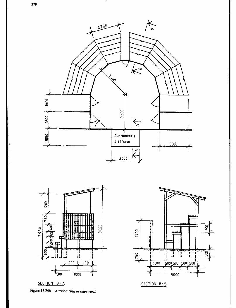
370
-I- L%!l I I ‘I
\ \ /’
SECTION A-A
Figure 13.24b Auction ring in sales yard.
SECTION B-B -

External Faciliries 371
Further Reading Road Construction de Veen J.J., 7&e Rural Access Roads Programme, Geneva, International Labour Organization, 1980. Hindson J., (rev. Howe J., Hathway G.), Earth Roods, ?7teir Construction ond Mointenonce, London, Intermediate
Technology Ltd., 1983. Longland F., (ed. Stem P.), Field Engineering, An Introducrion to Development Work and Construction in Rural Areas,
London, Intermediate Technology Ltd., 1983.
Fencing Ker A.D.R., et al., Agriculture in East Africa. London, Edward Arnold Ltd., 1979. Leighton J., Guide to Fencing, Supplement to the New Zealand Farmer, April 27, 1978. Midwest Plan Service, Beef Housing and Equipment Hondbook, Ames, Iowa, Midwest Plan Service, 1975. Pattison R.J., Cattle Handling Facilities, FAO Informal Technical Report No. 27 UNDP/ FAO/ ETH 72 006, 1974.
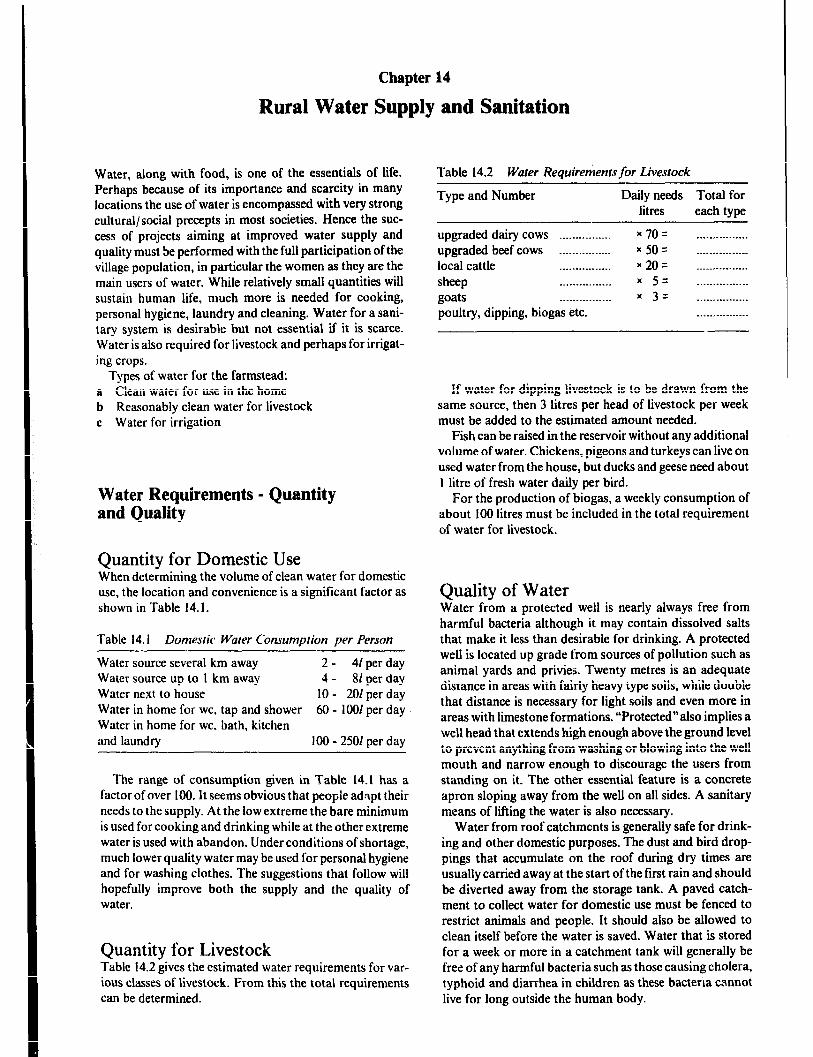
Chapter 14
Rural Water Supply and Sanitation
Water, along with food, is one of the essentials of life. Perhaps because of its importance and scarcity in many locations the use of water is encompassed with very strong cultural/social precepts in most societies. Hence the suc- cess of projects aiming at improved water supply and quality must be performed with the full participation of the village population, in particular the women as they are the main users of water. While relatively small quantities will sustain human life, much more is needed for cooking, personal hygiene, laundry and cleaning. Water for a sani- tary system is desirable but not essential if it is scarce. Water is also required for livestock and perhaps for irrigat- ing crops.
Types of water for the farmstead: a Clean water for use in the home b Reasonably clean water for livestock c Water for irrigation
Water Requirements - Quantity and Quality
Quantity for Domestic Use When determining the volume of clean water for domestic use, the location and convenience is a significant factor as shown in Table 14. I.
Table 14.1 Domesric Water Consumption per Person
Water source several km away 2- 41 per day Water source up to 1 km away 4 - 81 per day Water next to house 10 - 201 per day Water in home for WC. tap and shower 60 - 1001 per day Water in home for WC. bath, kitchen and laundry 100 - 2501 per day
The range of consumption given in Table 14.1 has a factor of over 100. It seems obvious that people adapt their needs to the supply. At the low extreme the bare minimum is used for cooking and drinking while at the other extreme water is used with abandon. Under conditions of shortage, much lower quality water may be used for personal hygiene and for washing clothes. The suggestions that follow will hopefully improve both the supply and the quality of water.
Quantity for Livestock Table 14.2 gives the estimated water requirements for var- ious classes of livestock. From this the total requirements can be determined.
Table 14.2 Water Requirerhents,for Livestock
Type and Number Daily needs Total for litres each type
upgraded dairy cows _.___... _.._ . . . . x 70 = . . . . ..-....... _. upgraded beef cows ._._.-...._..... * 50 = .._._..__.. _ .___ local cattle . . . . . . . . . . . . . . . . x 20 = . .._-.-*_-.._--. sheep . .._........._.. x 5 = . . . . . . .._....... goats r . . ..~........... 3 = . . . . . . . . . . . . . . . . poultry, dipping, biogas etc. . . . ..__.__...-__
If water for dipping livestock is to be drawn from the same source, then 3 litres per head of livestock per week must be added to the estimated amount needed.
Fish can be raised in the reservoir without any additional volume of water. Chickens, pigeons and turkeys can live on used water from the house, but ducks and geese need about 1 litre of fresh water daily per bird.
For the production of biogas, a weekly consumption of about 100 litres must be included in the total requirement of water for livestock.
Quality of Water Water from a protected well is nearly always free from harmful bacteria although it may contain dissolved salts that make it less than desirable for drinking. A protected well is located up grade from sources of pollution such as animal yards and privies. Twenty metres is an adequate distance in areas with fairly heavy type soils, while double that distance is necessary for light soils and even more in areas with limestone formations. “Protected”also implies a well head that extends high enough above the ground level to prevent anything from washing or blowing into the well mouth and narrow enough to discourage the users from standing on it. The other essential feature is a concrete apron sloping away from the well on all sides. A sanitary means of lifting the water is also necessary.
Water from roof catchmcnts is generally safe for drink- ing and other domestic purposes. The dust and bird drop- pings that accumulate on the roof during dry times are usually carried away at the start of the first rain and should be diverted away from the storage tank. A paved catch- ment to collect water for domestic use must be fenced to restrict animals and people. It should also be allowed to clean itself before the water is saved. Water that is stored for a week or more in a catchment tank will generally be free of any harmful bacteria suchas those causing cholera, typhoid and diarrhea in children as these bacteria cannot live for long outside the human body.

Rural Woter Supply and Sanitation 373
Streams and ponds, whether artificial or natural, are very likely to be contaminated and should be used for domestic purposes only as a last resort.
When the only water available is turbid (cloudy) and suspected of being polluted, it should be filtered through a well-designed sand filter. Even then, the safety of the water for drinking is questionable and boiling or other puriica- tion is recommended for complete safety.
Water Storage Long term storage of drinking water does not give rise to problems as long as the tank is always properly cleaned before the start of the rains, and the top of the tank is covered with line wire mesh (mosquito nets), to prevent small animals from drowing in the tank.
The use of chemicals, cooking or biological treatment of the water might be necessary, in order that good quality drinking water is obtained.
Catchment Areas The success of rain catchment depends on two things:
1 rainfall, and 2 adequate area and character of the catchment surface. The type of surface determines both the quality and quan- tity of water saved.
The catchment area can be divided into:
Total run-off oreos such as a hard roof surface or a protected paved area which allows the catching of nearly all the rain that falls on it. If surface dust and impurities are flushed away first, the water collected should be good for domestic use.
Partial run-off areas are hard surfaces such as rocky outcroppings, roads, and compounds which allow the catching of up to half the rain falling on the area. The water obvi ” i’..ly will not be as clean, but if stored properly should be sattsfactoty for livestock requirements.
Other surfaces, even though the soil may be quite loose or covered with vegetation, may have considerable run-off during hard rains. Water from these sources is likely to carry a considerable amount of sediment into the storage, making the water suitable only for crop irrigation.
If wells are dug close to surface water storages they can provide high quality water.
Roof Catchments The advantage of roof catchment systems is that even light rain showers will supply clean water and the total run-off is easily stored in a tank situated next to the house.
Types of Storage for Roof Catchments Granary Basket Tank (UNICEF design) is type of tank
uses a granary basket of woven sticks as a built-in frame- work for a cement-mortar plastered tank. The cost of the framework is only the labor of cutting and weaving sticks into an open-weave basket.
To improve strength and allow the construction of larger tanks, the outside of the basket can be covered with a layer of chicken wire after which barbed wire is wrapped with a 150mm spacing before the basket is plastered inside and out. A rich mortar of about 1:3 portland cement to sand should be used and mixed with just enough water to make the plaster easy to apply.
Without wire reinforcement the tank size should not exceed a diameter of 1.5m and a depth of 2m. If it is reinforced with barbed wire it should not exceed a diameter of 2.5m and a depth of 2m. A cover is desirable and can be made of mortar reinforced with chicken wire.
Figure 14.1 Reinforced mortar tank (Courtesy of Erik Nissen-Petersen).
Large cement jar is tank is a large bag with framework made of cloth or sacks and stuffed with sawdust, sand or rice hulls. Mortar is then plastered on to the bag, chicken wire and barbed wire are tied on to the plaster and another layer of plaster applied. The bag is removed from the inside of the jar after 24 hours, and plaster is applied to the inside to make it waterproof. The bag can be used for many water jars making the cost per tank minimal. A 1:3 portland cement to sand mortar is essential. The same size restric- tions apply as for the granary basket tank. In both this tank and the granary basket tank the curved sides contribute to the strength and life of the tank. A cover is desirable.
Concrete ring tank sections can be used to form water tanks of about 2,000 litres capacity. The small tank volumes are suitable for rain catchment from small roofs scattered on a compound and for areas with relatively even annual distribution of rainfall. A reinforced concrete cover should be installed. These tanks are particuiarly suitable where a form can be obtained for community use. With the casting done on site, expensive transportation is avoided.
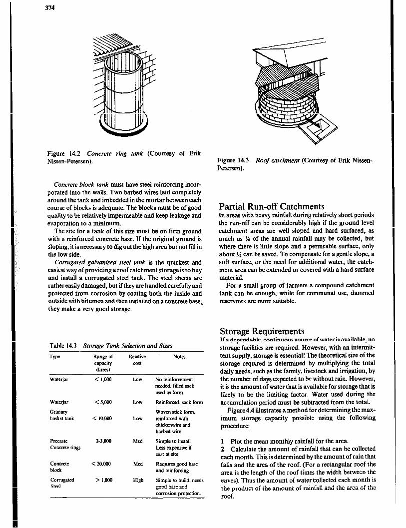
374
Figure 14.2 Concrete ring conk (Courtesy of Erik Nissen-Petersen).
Concrete block rank must have steel reinforcing incor- porated into the walls. Two barbed wires laid completely around the tank and imbedded in the mortar between each course of blocks is adequate. The blocks must be of good qua!ity to be relatively impermeable and keep leakage and evaporation to a minimum.
The site for a tank of this size must be on firm ground with a reinforced concrete base. If the original ground is sloping, it is necessary to dig out the high area but not fill in the low side.
Corrugated galvanised steel tank is the quickest and easiest way of providing a roof catchment storage is to buy and install a corrugated steel tank. The steel sheets are rather easily damaged, but if they are handled carefully and protected from corrosion by coating both the inside and outside with bitumen and then installed on a concrete base,- they make a very good storage.
Table 14.3 Storage Tank Selection and Sizes
Range of capacity Oitw
Relative cost
Notes
Watejar < I.ooa Low No reinforcement needed, filled sack osed as form
Watejar
Granary basket tank
< s.ooo
< 10,ooo
Low
LOW
Reinforced, sack form
Woven stick form, reinforced with chickenwire and barbed wire
Precaste Concrete rings
2-3.000 Med Simple to install Less expensive if cast at site
Concrete block
Corrugated Steel
< 2o.ooo
> l.cmo
Med
High
Requires good base and reinforcing
Simple to build, needs good base and corrosion protection.
Figure 14.3 Roof carchment (Courtesy of Erik Nissen- Petersen).
Partial Run-off Catchments In areas with heavy rainfail during relatively short periods the run-off can be considerably high if the ground level catchment areas are well sloped and hard surfaced, as much as % of the annual rainfall may be collected, but where there is little slope and a permeable surface, only about ‘/4 can be saved. To compensate for a gentle slope, a soft surface, or the need for additional water, the catch- ment area can be extended or covered with a hard surface material.
For a small group of farmers a compound catchment tank can be enough, while for communal use, dammed reservoirs are more suitable.
Storage Requirements If a dependable, continuous source of water is available, no storage facilities are required. However, with an intermit- tent supply, storage is essential! The theoretical size of the storage required is determined by multiplying the total daily needs, such as the family, livestock and irrigation, by the number of days expected to be without rain. However, it is the amount of water that is available for storage that is likely to be the limiting factor. Water used during the accumulation period must be subtracted from the total.
Figure 4.4 illustrates a method for determining the max- imum storage capacity possible using the following procedure:
1 Plot the mean monthly rainfall for the area. 2 Calculate the amount of rainfall that can be collected each month. This is determined by the amount of rain that falls and the area of the roof. (For a rectangular roof the area is the length of the roof times the width between the eaves). Thus the amount of watercollected each month is the product of the amount of rainfall and the area of the roof.
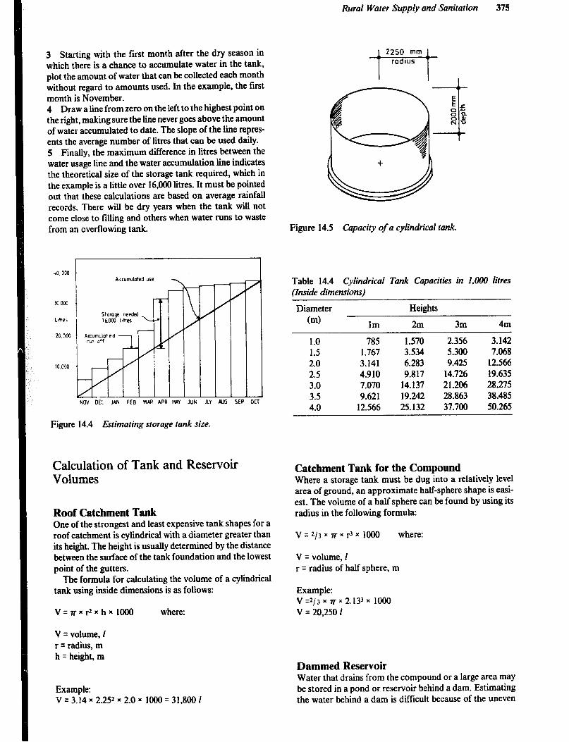
Rural Water Supply and Sanitation 375
3 Starting with the first month after the dry season in which there is a chance to accumulate water in the tank, plot the amount of water that can be collected each month without regard to amounts used. In the example, the first month is November. 4 Draw a line from zero on the left to the highest point on the right, making sure the line never goes above the amount of water accumulated to date. The slope of the line repres- ents the average number of litres that can be used daily. 5 Finally, the maximum difference in litres between the water usage line and the water accumulation line indicates the theoretical size of the storage tank required, which in the example is a little over 14,OUO litres. It must be pointed out that these calculations are based on average rainfall records. There will be dry years when the tank will not come close to filling and others when water runs to waste from an overflowing tank.
40,000
32 00:
L8hQ5
20,300
10.000
Acrunwkded use
W OEC JAN FEB MAR APR HAY JUN JLY AJJG t
I
Figure 14.4 fibmating storage tank size.
1 7
oc
Calculation of Tank and Reservoir Volumes
Roof Catchment Tank One of the strongest and least expensive tank shapes for a roof catchment is cylindrical with a diameter greater than its height. The height is usually determined by the distance between the surface of the tank foundation and the lowest point of the gutters.
The formula for calculating the volume of a cylindrical tank using inside dimensions is as follows:
V=rrxr2xhxlOOO where:
V = volume, I r = radius, m h q height, m
Example: v = 3.14 x 2.252 x 2.0 x 1000 = 31,800 1
Figure 14.5 Capacity of a cylindrical tank.
Table 14.4 Cylindrical Tank Capacities in 1.000 l&es &side dimensions)
Diameter
(ml Im
Heights
2m 3m 4m
1.0 785 1.570 2.354 3.142 1.5 1.747 3.534 5.300 7.068 2.0 3.141 4.283 9.425 12.566 2.5 4.910 9.817 14.724 19.435 3.0 7.070 14.137 21.206 28.275 3.5 9.421 19.242 28.843 38.485 4.0 12.566 25.132 37.700 50.245
Catchment Tank for the Compound Where a storage tank must be dug into a relatively level area of ground, an approximate half-sphere shape is easi- est. The volume of a half sphere can be found by using its radius in the following formula:
V=2/3~7rxr3xlOOO where:
V = volume, 1 r q radius of half sphere, m
Example: V=2/3~~~2.133~l~ V = 20,250 1
Dammed Reservoir Water that drains from the compound or a large area may be stored in a pond or reservoir behind a dam. Estimating the water behind a dam is difficult because of the uneven
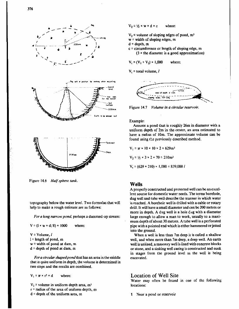
376
Figure 14.6 Halfsphere lank.
topography below the water level. Two formulas that will help to make a rough estimate are as follows:
For a long narrow pond, perhaps a dammed-up stream:
V q (1 x w x d/8) x 1000 where:
V = Volume, i 1 = length of pond, m w = width of pond at dam, m d = depth of pond at dam, m
For a circular shupedpondthat has an area in the middle that is quite uniform in depth, the volume is determined in two steps and the rest&s are combined.
Vt=rrxrZxd where:
Vt q volume in uniform depth area, rn’ r = radius of the area of uniform depth, m d q depth of the uniform area, m
V2=1/4XwXdXc where:
V2 = volume of sloping edges of pond, mJ w = width of sloping edges, m d = depth, m c = circumference or length of sloping edge, m
(3 x the diameter is a good approximation)
v, = (V, + v2) x 1,000 where:
V, = total volume, I
Figure 14.7 Volume in a circular reservoir.
Example: Assume a pond that is roughly 26m in diameter with a
uniform depth of 2m in the center, an area estimated to have a radius of 1Om. The approximate volume can be found using the previously described method.
VI = n x 10 x 10 x 2 = 629m3
Vz = ‘A x 3 x 2 x 70 = 210m3
V;= (629 + 210) x 1,000 = 839,000 I
Wells A properly constructed and protected well can be an excel- lent source for domestic water needs. The terms borehole, dug well and tube well describe the manner in which water is reached. A borehole well is drilled with a cable or rotary drill. It will have a small diameter and can be 200 metres or more in depth. A dug well is a hole &tg with a diameter large enough to allow a man to work, usually to a maxi- mum depth of about 30 metres. A tube well is a perforated pipe with a pointed end which is either hammered or jetted into the ground.
When a well is less than 7m deep it is called a shallow well, and when more than 7m deep, a deep well. An earth well is unlined, a masonry well is lined with concrete blocks or stone, and a sinking well casing is constructed and sunk in stages from the ground level as the well is being excavated.
Location of Well Site Water may often be found in one of the following locations:
1 Near a pond or reservoir

Rural Water Supply and Sanitation 377
2 In the foothills near mountains and especially near green trees or holes dug by animals 3 In areas of green vegetation during drought 4 Near existing wells or waterholes 5 In sandy rirzi beds, especially upstream from bed rock, where temporary wells may be dug
Types of Well Casings There are several methods of constructing well casings, the one chosen depending on purpose, soil structure, water source and local skills.
Oil barrel well are used to form this inexpensive well casing. The barrels are perforated to allow the entry of water. The life of this casing will be shorter than with other materials ‘A id the residue in the barrels may pollute the water so that it is unfit for domestic use.
Ferrocement well is a type of earth wall well that is excavated to a straigh! ?nd smooth surface which is then plastered with a layer oi mortar, reinforced with chicken wire, and finally plastered a second time.
A well head is built above ground level to limit the risk of children and animals falling into the well. To prevent contamination of the well a concrete apron, sloping away from the well head, is constructed on the surrounding ground.
Figure i4.8 Ferrocemenr well (Courtesy of Erik Nissen Petersen).
Sinking wells are so named because the casing is sunk into place. The method works well in sandy soils. Figures 14.9 and 14.10 show casings that can be sunk into place.
Concrete ring well is a method that requires either a steel casing ring mould for casting the concrete rings on site or for precast rings to be purchased and transported from factory to construction site. Both alternatives are expensive for a single well, but feasible when a number of wells are
being constructed in a local area. The rings, measuring 0.9m in diameter and 0.5m in height are stacked upon each other in an excavated well hole, or they can be used for sinking wells or a combination of both procedures,
Figure 14.9 Concrete ring well (sinking well).
Chcrete block well is a less expensive alternative to concrete rings is the use of concrete blocks shaped in a wooden form. These blocks are stacked on a concrete foundation ring which can be cast in a wooden form, or more cheaply, in a ditch in the soil at the construction site.
With either type of casing, by digging soil out from under the bottom of the casing, the whole structure will be allowed to settle. When the top of the well casing has reached the surface of the surrounding soil another section is added to the top. Thereafter digging is repeated until another section can be added on to the well at ground level, and so on until a satisfactory depth has been reached. The blocks must be tied together with vertical reinforcing rods to ensure that the casing sinks as a single unit.
\
Figure 14.10a Concrete block weil (sinking well).

378
Figure 14.10b Section offoundation and reinforcement (Courtesy of Erik Nissen-Petersen).
Lifts for Wells The simplest means of lifting water from dug wells such as a rope and calabash or a bucket and windlass have been used for centuries and unfortunately they continue to be used today in many parts of the world. The objection to their use is that too often they are a source of pollution both because the top of the well is open and because the water vessel is frequently set down on a badly polluted surface. An improved variation of these methods has a bucket with a h,Jse attached to the bottom and to an outiet at the wellhead as shown in Figure 14.1 t When the bucket is lifted water is discharged from the outlet while the top of the well remains covered.
Figure 14.11 Bucket lfl in closed well (Courtesy of Erik Nissen-Petersen).
Pumps A pump is the most convenient and sanitary means of lifting water from a well or any other low level water supply. Pumps may be hand or power operated, designed to lit only or to lift and discharge against pressure and to lift from either shallow or deep wells.
As mentioned earlier, shallow wells are those in which the low water level is 7m or less below the pump. In deep
wells the water level may drop well below the 7m mark. The maximum suction lift for shallow-well pumps of any type is reduced about lm per 1OOOm of site elevation.
Hand Pumps The simplest hand pump, often referred to as a pitcher pump, is satisfactory for use on wells or cisterns in which the water never needs to be lifted more than about 6m. A cross section of a pitcher pump is shown in Figure 14.12. If these pumps are AMiAtaiAed in good COAditiOA, they are easily primed and will hold their prime from one use to the next. However, if the valves leak, the pump will need to be primed each time it is used. This is not only a nuisance but can be a source of pollution from the priming water.
Water from deep wells is lifted with a similar plunger type pump in which the cylinder, including the plunger and valves, is supported on the discharge pipe deep enough in the well to be submerged in water at all times. The pump handle is connected to the plunger by means of a long rod. While this type of pump is self-priming due to the cylinder being submerged in the water, it must nevertheless be maintained in good cc edition to work effectively. Figure 14.13 illustrates a deep-well pump. Both of these pumps allow the well top to be completely covered for maximum protection against pollution.
Occasionally it is necessary to use a hand pump to force water above the level of the pump. Models are av,zilable that are designed with a packing around the liit rod and a pipe connection at the point of discharge enabling them to force water to a tank higher than the pump. An even more sophisticated model is equipped with a small “differential” cylinder that causes the pump to discharge on both the “up” and “down” strokes.
Power Driven Pumps There are a number of pumps on the market from which to select for a particular application. They all have character- istics which infhrence their suitability for a specific water supply as well as the volume aAd pressure required.
Centrifugal pumps are simple (only one moving part), durable, and relatively inexpensive for a given capacity. However, they are suitable only for low lifts of 3 to 4m and are prone to losing their prime unless the suction pipe is equipped with a good foot valve (check valve). Neither will they discharge against a very high head (pressure).
There are several designs of centrifugal pumps that further influence one’s choice. The impeller may be an open type with a relatively large clearance between it and the casing or it may be a closed type with very close clearances. The open type will tolerate sand or silt in the water much better than the closed-impeller type. (Figure 14.14 and 14.15).
A centrifugal pump may have an integral electric motor or petrol-powered engine which the manufacturer wil! have sized correctly, or it may have a belt drive. IA the latter case, great care must be taken to drive the pump at a suitable speed and with a motor or engine of adequate power.
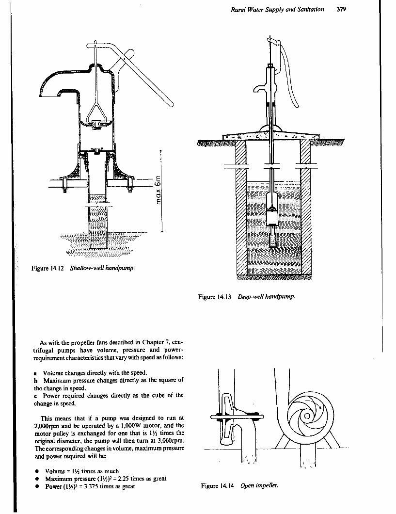
Rural Water Supply and Sanitation
Figure 14.12 Shallow-well handpump.
Figure 14.13 Deep-well hanc@ump.
As with the propeller fans described in Chapter 7, cen- trifugal pumps have volume, pressure and power- requirement characteristics that vary with speed as follows:
a Voisme changes directly with the speed. b Maximum pressure changes directly as the square of the change in speed. c Power required changes directly as the cube of the change in speed.
This means that if a pump was designed to run at 2,OOOrpm and be operated by a 1,OOOW motor, and the motor pulley is exchanged for one that is 1% times the original diameter, the pump will then turn at 3,Oorpm. The corresponding changes in volume, maximum pressure and power required will be:
m Volume = 1 l/i times as much a Maximum pressure (1 IA)2 q 2.25 times as great 0 Power (11593 = 3.375 times as great Figure 14.14 Open impeller.
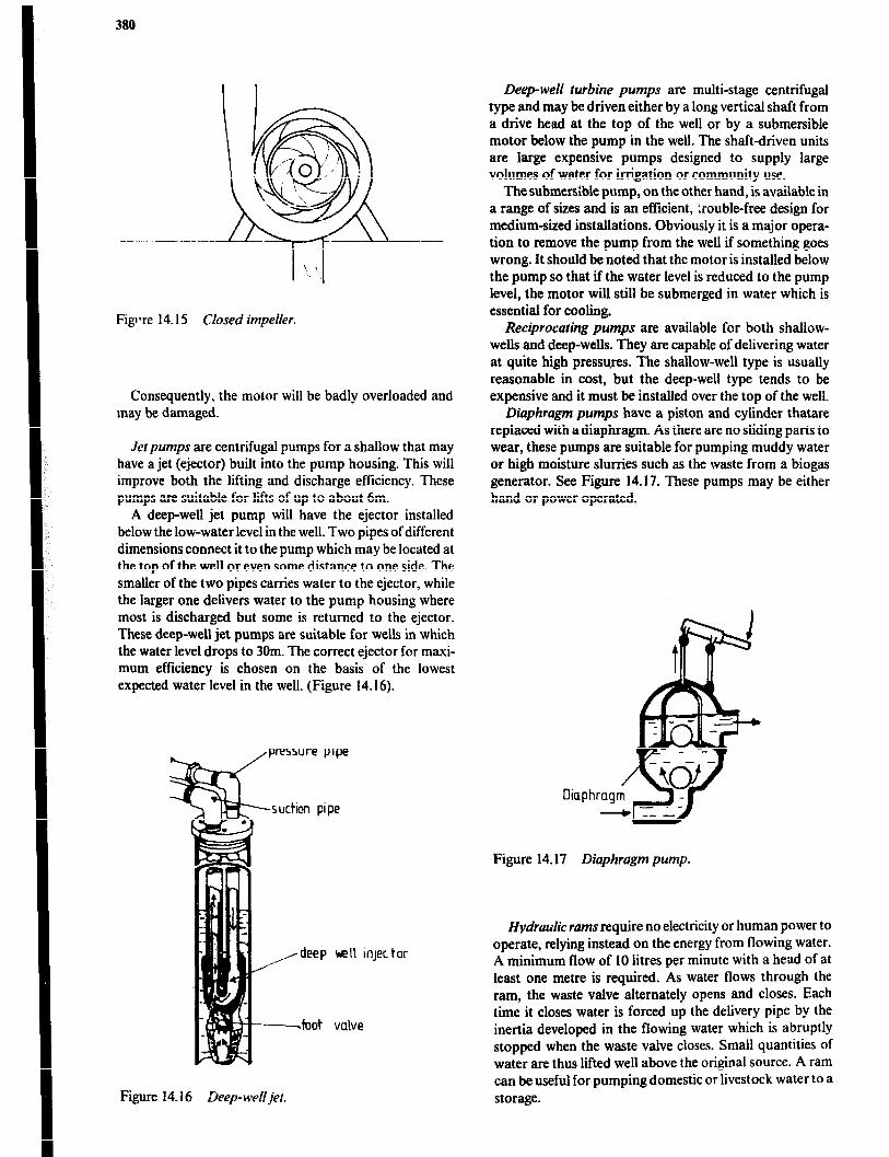
380
Figrre 14.15 Closed impeller.
Consequently, the motor will be badly overloaded and may be damaged.
Jet pumps are centrifugal pumps for a shallow that may have a jet (ejector) built into the pump housing. This will improve both the lifting and discharge efficiency. These pumps are suitable for lifts of up to about 6m.
A deep-well jet pump will have the ejector installed below the low-water level in the well. Two pipes of different dimensions connect it to the pump which may be located at the top of the well or even some distance to one side. The smaller of the two pipes carries water to the ejector, while the larger one delivers water to the pump housing where most is discharged but some is returned to the ejector. These deep-well jet pumps are suitable for wells in which the water level drops to 30m. The correct ejector for maxi- mum efficiency is chosen on the basis of the lowest expected water level in the well. (Figure 14.16).
Figure 14.16 Deep-well jet.
tor
Deep-well turbine pumps are multi-stage centrifugal type and may be driven either by a long vertical shaft from a drive head at the top of the well or by a submersible motor below the pump in the well. The shaftdriven units are large expensive pumps designed to supply large volumes of water for irrigation or community use.
The submer&ble pump, on the other hand, is available in a range of sizes and is an efficient, Lrouble-free design for medium-sized installations. Obviously it is a major opera- tion to remove the pump from the well if something goes wrong. It should be noted that the motor is installed below the pump so that if the water level is reduced to the pump level, the motor will still be submerged in water which is essential for cooling.
Reciprocating pumps are available for both shallow- wells and deep-wells. They are capable of delivering water at quite high pressures. The shallow-well type is usually reasonable in cost, but the deep-well type tends to be expensive and it must be installed over the top of the well.
Diaphragm pumps have a piston and cylinder thatare replaced with a diaphragm. As there are no sliding parts to wear, these pumps are suitable for pumping muddy water or high moisture slurries such as the waste from a biogas generator. See Figure 14.17. These pumps may be either hand or power operated.
Diaph
Figure 14.17 Diaphragm pump.
Hydraulic rams require no electricity or human power to operate, relying instead on the energy from flowing water. A minimum flow of 10 litres per minute with a head of at least one metre is required. As water flows through the ram, the waste valve alternately opens and closes. Each time it closes water is forced up the delivery pipe by the inertia developed in the flowing water which is abruptly stopped when the waste valve closes. Small quantities of water are thus lifted well above the original source. A ram can be useful for pumping domestic or livestock water to a storage.

Kurul Water Supply md Sanirakm 381
Commercial rams are available in a number of sizes that can pass supply-flow rates from 10 to 400 litres per minlrte and can discharge to maximum heights of 100 to 150m. Although a ram will operate at as little as 1 melre of head, larger heads will increase discharge rates considerably, e.g. increasing supply head from 1 to 1Om can increase delivery by up to 20 times. It is necessary to know the flow rate of the water supply and the head which is possible before purchasing a ram. The first cost is substantial, but mainte- nance is low, life is long and operating cost is nil, so if the natural conditions are available, a hydraulic ram can be a very good investment.
Choosing a Pump Five main factors must be considered when selecting a pump:
I the total water required per day; 2 the maximum rate I;! flow desired; 3 the maximum fi~w frcm the water source; 4 the vertical dislance ihe water must be lifted to the pump; 5 the total head against which the pump must operate.
The terms head and pressure are used interchangeably. The unit of measure of pressure is the Pascal (Pa) while the unit of measure of head is the metre (m). One metre of water column = 9.8 kPa. Head is frequently used in discuss- ing pump installations because there will be vertical distan- ces from water level to pump and pump to point of dis- charge. Pipe friction tables are often given in terms of loss of head per unit of pipe length.
The daily water requirement influences pump size in that it is desirable for the pump to operate not more than 25% of the time.
Header tank
The maximum rate of flow is determined by totaling suitable flow rates from all of the discharge openings that may be operating at one time. If the source of water is a dug well, pond or stream, undoubtedly the desired flow rate can be used in choosing a pump. However, if the source is a borehole or driven well with very low storage capacity, there is no alternative but to choose a pump that does not have a capacity In excess of the flow rate of the well.
The vertical distance between low water level and the location of the pump is the primary factor in the type of pump chosen, although the total head is also significant. Total head is made up of:
a lifting head from well to pump, b vertical discharge head from pump to point of use, c working head or pressure at the point of use, and d friction losses due to flow through pipe and fittings.
Pump Storage Tanks Regardless of the type of pump chosen, it must either discharge into a tank or have an open pipe discharge into an irrigation channel. Operating any of the centrifugal pumps against a closed line results in overheating and damaged shaft seals. Operating a reciprocating pump against a closed line will result in a stalled motor or the physical breaking of some part in the pump.
Hydropneumatic Systems These systems consist of an enclosed tank combined with an automatic pressure switch which turns the pump motor on when tank pressure drops to a preset level. As the tank is approximately half full of air, seyeral litres of water can be pumped into the tank before the air is compressed and the
lmpul se dock vulve
A
AIR
Figure 14.18 Hydraulic ram.
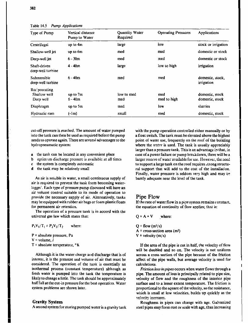
382
Table 14.5 Pump Applications
Type of Pump Vertical distance Quantity Water Pump to Water Required
Operating Pressures Applications
Centrifugal
Shallow-well jet
Deep-well jet
Shaft-driven deep-well turbine
Submersible deep-well turbine
Rec’procating Shallow well Deep well
Diaphragm
Hydraulic ram
up to 4m
up to 6m
6-30m
4-40m
6-40m
up to 7m 6-40m
up to 5m
(-14
large
med
med
large
med
low to med med
med
small
low
med
med
low to high
med
med med to high
low
med
stock or irrigation
domestic or stock
domestic or stock
irrigation
domestic, stock, irrigation
domestic, stock domestic, stock
slurries
domestic, stock
cut-off pressure is reached. The amount of water pumped into the tank can then be used as required before the pump needs to operate again. There are several advantages to the hydropneumatic system:
a the tank can be located in any convenient place b optim!im discharge pressure is available at all times c the system is completely automatic d the tank may be relatively small
As air is solrible in water, a small continuous supply of air is required to prevent the tank from becoming water- loggec’. Each type of pressure pump discussed will have an air volume control suitable to its mode of operation to provide the necessary supply of air. Alternatively, tanks may be equipped with rubber air bags or foam plastic floats for permanent air retention.
The operation of a pressure tank is in accord with the universal gas law which states that:
PIVI/TI = bVdT2 where:
P = absohtte pressure, Pa V = volume, i T q absolute temperature, ‘IL
Although it is the water charge and discharge that is of interest, it is the pressure and volume of air that must be considered. The operation of the tank is essentially an isothermal process (constant temperature) although as fresh water is pumped into the tank the temperature is likely to change a little. The tank should be approximately half full at the cut-in pressure for the best operation. Water system problems are shown later.
Gravity System A second system for storing pumped water is a gravity tank
with the pump operation controlled either manually or by a float switch. The tank must be elevated above the highest point of water use, frequently on the roof of the building where the water is used. The tank is usually appreciably larger than a pressure tank. This is an advantage in that, in case of a power failure or pump breakdown, there will be a larger reserve of water available for use. However, the need to support a large tank on the roof requires Jtrong structu- ral support that will add to the cost of the installation. Finally, water pressure is seldom very high and may be barely adequate near the level of the tank.
Pipe Flow If the rate of water flow in a pipe system remains constant, the equation of continuity of flow applies; that is:
Q = A x V .where:
Q q flow (m3/s) A = cross-section area (m*) V = velocity (m/s)
If the area of the pipe is cut in half, the velocity of fiow will be doubled and so on. The velocity is not uniform across a cross section of the pipe because of the friction affect of the pipe walls, but average velocity is used for calculations.
Friction loss inpipes occurs when water flows through a pipe. The amount of loss is principally related to pipe size, velocity of flow and the roughness of the interior pipe surface and to a lesser extent temperature. The friction is proportional to the square of thevelocity, so the resistance, which is small at low velocities, builds up quickly as the velocity increases.
Roughness in pipes can change with age. Galvanized steel pipes may form rust or scale with age, thus increasing
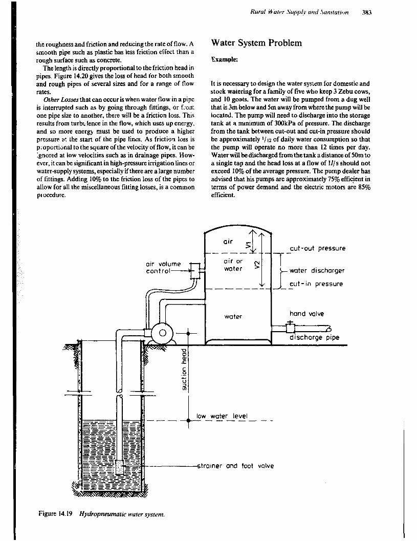
the roughness and friction and reducing the rate of flow. A smooth pipe such as plastic has less friction effect than a rough surface such as concrete.
The length is directly proportional to the friction head in pipes, Figure 14.20 gives the loss of head for both smooth and rough pipes of several sizes and for a range of flow rates.
Other Losses that can occur is when water flow in a pipe is interrupted such as by going throslgh fittings, or f:o‘m one pipe size to another, there will be a friction loss. This results from turbo lence in the flow, which uses up energy, and so more energy must be used to produce a higher pressure s: the start of the pipe lines. As friction loss is proportional to the square of the velocity of flow, it can be ignored at low velocities such as in drainage pipes. How- ever, it can be significant in high-pressure irrigation lines or water-supply systems, especially if there are a large number of fittings. Adding 10% to the friction loss of the pipes to allow for all the miscellaneous fitting losses, is a common procedure.
Water System Problem
Example:
It is necessary to design the water system for domestic and stock watering for a family of five who keep 3 Zebu cows, and 10 goats. The water will be pumped from a dug well that is 3m below and 5m away from where the pump will be located. The pump will need to discharge into the storage tank at a mmimum of 300kPa of pressure. The discharge from the tank between cut-out and cut-in pressure should be approximately I/ 12 of daily water consumption so that the pump will operate no more than 12 times per day. Water will be d&barged from the tank a distance of 50m to a single tap and the head loss at a flow of U/s should not exceed 10% of the average pressure. The pump dealer has advised that his pumps are approximately 75% effrcjent in terms of power demand and the electric motors are 85% efficient.
c low water level --- -----
w-e-- ----- ----- --v-e ---- ---- -- --es-. ----. mtratner and foot
--
valve
cut-out Dressure -- 1
+ water discharger 1
J cut-in pressure --
hand valve
b discharge pipe
Figure 14.19 Hydropneumatic water system.
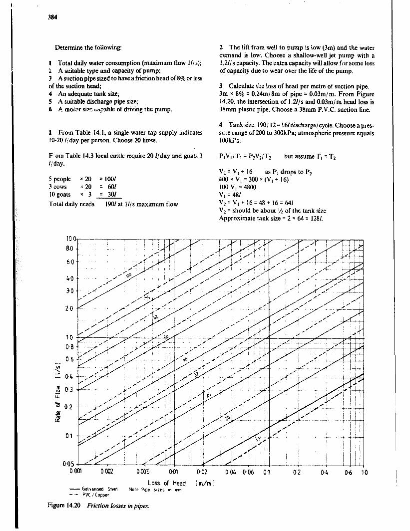
Determine the following:
1 Total daily water consumption (maximum flow 1 l/s); Z A suitable type and capacity of pump; 3 A suction pipe sized to have a friction head of 8% or less of the suction head; 4 An adequate tank size; 5 A suitable discharge pipe size; 6 A mo&r siz r;+*ble of driving the pump.
1 From Table 14.1, a single water tap supply indicates IO-20 I/day per person. Choose 20 litres.
F.-om Table 14.3 local cattle require 20 l/day and goats 3 I/ day.
5 people x 20 = 1001 3 cows ‘( 20 = 601 10 goats x 3 = 301
Total daily needs 1901 at Ii/s maximum flow
2 The lift from well to pump is low (3m) and the water demand is low. Choose a shallow-well jet pump with a 1.21/s capacity. The extra capacity will allow fr;r some loss of capacity due to wear over the life of the pump.
3 Calculate tbe loss of head per metre of suction pipe. 3m x 8% = 0.24m/8m of pipe q O.O3m/m. From Figure 14.20, the intersection of 1.21/s and O.O3m/m head loss is 38mm plastic pipe. Choose a 38mm P.V.C. suction line.
4 Tank size. 190/ 12 2: Nildischarge/ cycle. Choose a pres- stire range of 200 to 3OQkPa; atmospheric pressure equals IOOkTc.
PIVI/TI = P2V2/J-2 but assume TI = T2
Vt q V; + 16 as PI drops to Pz 400 x v, = 300 x (V, + 16) 100 VI = 4800 V, = 481 v2=v,+ 16=48+16= 641 VI = should be about I% of the tank size Approximate tank size q 2 x 64 = 1281.
0001 0002 0.005 001 0.02 0 04 Oi6 0.1 0.2 0.4 06 I.0
Loss of Head [m/m 1
- Gaivansed St& Note Ptpe sacs m mm - - PVC / copper
Figure 14.20 Friction losses in pipes.
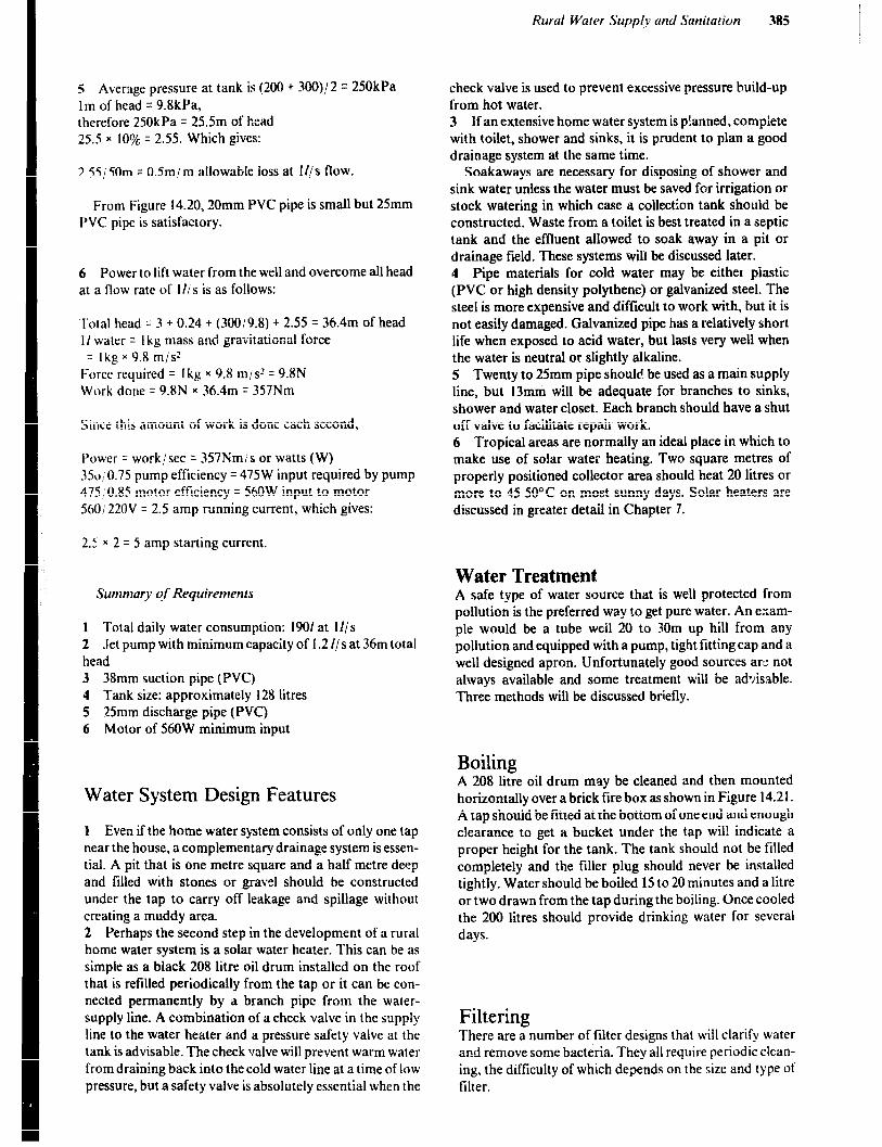
s Aversge pressure at tank is (200 + 300)/ 2 = 250kPa 1 m of head = 9.8kPa. therefore 250kPa = 25.5m of head 25.5 x lO$!+ = 2.55. Which gives:
2.55150m = O.Sm/m allowable loss at I//s flow.
From Figure 14.20,20mm PVC pipe is small but 25mm PVC pipe is satisfactory.
6 Power to lift water from the well and overcome all head at a flow rate of l//s is as follows:
Total head = 3 + 0.24 + (3OOi9.8) + 2.55 = 36.4m of head I I water = I kg mash and gravitational force = Ikg x 9.8 m/s2
Force required = I kg x 9.8 m/s” = 9.8N Work done q 9.RN * 36.4m = 357Nm
Since this amount of work is done each second,
Power = workisec = 357Nmis or watts (W) 35~~~0.75 pump efficiency = 475W input required by pump 475,0.85 motor efficiency = 56OW input to motor %0!‘220V = 2.5 amp running current, which gives:
2.5 x 2 = 5 amp starting current.
Summar)~ qf Requirements
1 Total daily water consumption: 1901 at Ills 2 Jet pump with minimum capacity of 1.2 I/s at 36m total head 3 38mm suction pipe (PVC) 4 Tank size: approximately 128 litres 5 25mm discharge pipe (PVC) 6 Motor of 560W minimum input
Water System Design Features
1 Even if the home water system consists of only one tap near the house, a complementary drainage system is essen- tial. A pit that is one metre square and a half metre deep and filled with stones or gravel should be constructed under the tap to carry off leakage and spillage without creating a muddy area. 2 Perhaps the second step in the development of a rural home water system is a solar water heater. This can be as simple as a black 208 litrt: oil drum installed on the roof that is refilled periodically from the tap or it can be con- nected permanently by a branch pipe from the water- supply line. A combination of a check valve in the supply line to the water heater and a pressure safety valve at the tank is advisable. The check valve will prevent warm water from draining back into the cold water line at a time of low pressure, but a safety valve is absolutely essential when the
check valve is used to prevent excessive pressure build-up from hot water. 3 If an extensive home water system is p!anned, complete with toilet, shower and sinks, it is prudent to plan a good drainage system at the same time.
Soakaways are necessary for disposing of shower and sink water unless the water must be saved for irrigation or stock watering in which case a collection tank should be constructed. Waste from a toilet is best treated in a septic tank and the effluent allowed to soak away in a pit or drainage field. These systems will be discussed later. 4 Pipe materials for cold water may be either piastic (PVC or high density polythene) or galvanized steel. The steel is more expensive and difficult to work with, but it is not easily damaged. Galvanized pipe has a relatively short life when exposed to acid water, but lasts very well when the water is neutral or slightly alkaline. 5 Twenty to 25mm pipe should be used as a main supply line, but 13mni will be adequate for branches to sinks, shower and water closet. Each branch should have a shut off valve to facilitate repair work. 6 Tropical areas are normally an ideal place in which to make use of solar water heating. Two square metres of properly positioned collector area should heat 20 litres or more to 4%50°C on most sunny days. Solar heaters are discussed in greater detail in Chapter 7.
Water Treatment A safe type of water source that is well protected from pollution is the preferred way to get pure water. An exam- ple would be a tube weil 20 to 30m up hill from any pollution and equipped with a pump, tight fitting cap and a well designed apron. Unfortunately good sources ar;: not always available and some treatment will be ad&able. Three methods will be discussed briefly.
Boiling A 208 litre oil drum may be cleaned and then mounted horizontally over a brick fire box as shown in Figure 14.2 1. A tap should be fitted at the bottom of one end and enough clearance to get a bucket under the tap wil! indicate a proper height for the tank. The tank should not be filled completely and the filler plug should never be installed tightly. Water should be boiled 15 to 20 minutes and a litre or two drawn from the tap during the boiling. Once cooled the 200 litres should provide drinking water for several days.
Filtering There are a number of filter designs that will clarify water and remove some bacteria. They all require periodic clean- ing, the difficulty of which depends on the size and type 01 filter.
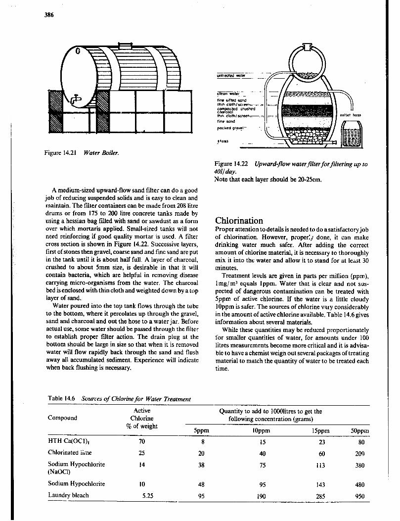
386
Figure 14.21 Water Boiler.
Figure 14.22 Upward-flow waterfiirerforjiltering up to IN/day. Note that each layer should be 20-25cm.
A medium-sized upward-flow sand filter can do a good job of reducing suspended solids and is easy to clean and maintain. The filter containers can be made from 208 litre drums or from 175 to 200 litre concrete tanks made by using a hessian bag filled with sand or sawdust as a form over which mortaris applied. Small-sized tanks will not need reinforcing if good quality mortar is used. A filter cross section is shown in Figure 14.22. Successive layers, first of stones then gravel, coarse sand and fine sand are put in the tank until it is about half full. A layer of charcoal, crushed to about 5mm size, is desirable in that it will contain bacteria, which are helpful in removing disease carrying micro-organisms from the water. The charcoal bed is enclosed with thin cloth and weighted down by a top layer of sand.
Water poured into the top tank flows through the tube to the bottom, where it percolates up through the gravel, sand and charcoal and out the hose to a water jar. Before actual use, some water should be passed through the filter to establish proper filter action. The drain plug at the bottom should be large in size so that when it is removed water will flow rapidly back through the sand and flush away all accumulated sediment. Experience will indicate when back flushing is necessary.
Chlorination Proper attention to details is needed to do a satisfactory job of chlorination. However, properzg done, it can make drinking water much safer. After adding the correct amount of chlorine material, it is necessary to thoroughly mix it into the water and allow it to stand for at least 30 minutes.
Treatment levels are given in parts per million (ppm), lmg/mJ equals Ippm. Water that is clear and not sus- pected of dangerous contamination can be treated with Sppm of active chlorine. If the water is a little cloudy 1Oppm is safer. The sources of chlorine vary considerably in the amount of active chlorine available. Table 14.6 gives information about several materials.
While these quantities may be reduced proportionately for smaller quantities of water, for amounts under 100 litres measurements become more critical and it is advisa- ble to have a chemist weign out several packages of treating material to match the quantity of water to be treated each time.
Table 14.6 Sources of Chlorinefor Water Treatment
Active Quantity to add to 1OOOlitres to get the Compound Chlorine following concentration (grams)
% of weight 5wm lowm 15wm 5oppm
HTH Ca(OCl), 70 8 15 23 80
Chlorinated iihne 25 20 40 60 200
Sodium Hypochlorite 14 38 75 113 380 (NaOCl)
Sodium Hypochlorite 10 48 95 143 480
Laundry bleach 5.25 95 190 285 950 ---

Rural Wkter Supply and Sanirh:ion 387
The 50ppm column is shown in the tabie as being the level at which to treat a new or repaired well or cistern. The dosage is left for 24 hours before flushing out.
Open Channel Flow A knowledge of the principles of open channel flow is necessary in designing ditches to carry water into grade level storages and channels to carry away storm water without causing erosion. The same principles apply to the design of irrigation canals, road splashes and d&B. The most common problems are:
1 Estimating the flow in a channel when the cross-section gradient, depth, etc. are known or can be measured. This is useful in planning irrigation canals, ditches, and natural watercourses; 2 Estimating the depth of flow at which a given channel will carry a given rate of flow. This can be useful in estimat- ing how high a river flood crest will rise, or how deep the flow will be in an irrigation channel or over a drift; 3 Designmg a channel lo carry agiven rate offlow. This is useful in designing channels to carry storm run-off away from buildings or other structures; 4 Designing a channel to carry un estimated maximum flow, when the velocity must not exceedagiven maximum value. This is a problem of designing stormwater diversion drams or other unlined channels when the velocity must be low enough to avoid scouring of the channel. A suitable cross seclion and gradient must be chosen.
The quantity of water flowing in an open drainage chan- nel is the product of the cross-section area of the channel and the speed of flow.
Q=AxV where:
Q is the flow in cubic metres per second (mJ/s) A is the cross-section area of the channel (m2) V is the average velocity of flow (m/s)
If the velocity is checked at any cross section in a channel it will be found that the water is flowing slower along the sides and bottom. This is due to frictional resistance and is more pronounced along vegetated than paved channels. In practice, however, a theoretical average velocity is used.
The equation of continuity shows that for a constant discharge, Q, the velocity must change inversely with the section area of the channel.
Q = A, x V, = A2 x Vz = A, x VJ
There are twc types of flow in a channel which may give the same discharge but at different velocities and depths. A rapid, shallow flow is called super-criticalor shooting flow. A deeper, slower flow is called sub-critical flow. An exam- ple of each type of flow is found on a dam spillway. The thin layer rushing down the spillway surface is super- critical flow. After hitting the standing wave at the bottom
the water moves away much more slowly in a sub-critical flow. In general, super-critical flow should be avoided as erosion will occur in all channels which are not lined with concrete.
The velocity of flow in a channel is determined by the gradient, the shape and size of the cross section and the roughness of the surfaces. It is quite obvious that the velocity will be greater in steep, smooth channels. It is not as obvious that two channels with the same cross-section area but with different shapes can have different velocities. This results from the differing amount of surface contact and frictional resistance.
The effect of cross-section shape is measured by the hydraulic radius of the channel (R). It is found by the equation:
R=A/P where:
R = hydraulic radius, m A = Cross-section area, m2 P = wetted perimeter, m
The wetted perimeter is the length of the cross section in contact with the water. Figure 14.23 illustrates the effect of shape on the hydraulic radius. Both channels have an area of 24, but a) has a huger R.
Figure 14.23a R = 24114 .
‘1 r; 12
Figure 14.23b R = 24116
Figure 14.23 Channels of equal area but diJferent hydrauiic radii.
When other factors are equal, the channel with the !arger R will have the higher channel velocity.
The two most common shapes for earth channels are shown in Figure 14.24. The trapazoidal shape has a ten- dency to gradually change to the parabolic shape over a period of time.
The variables which affect the velocity of flow are related as shown in the empirical equation called the Manning formula for open channel flow.
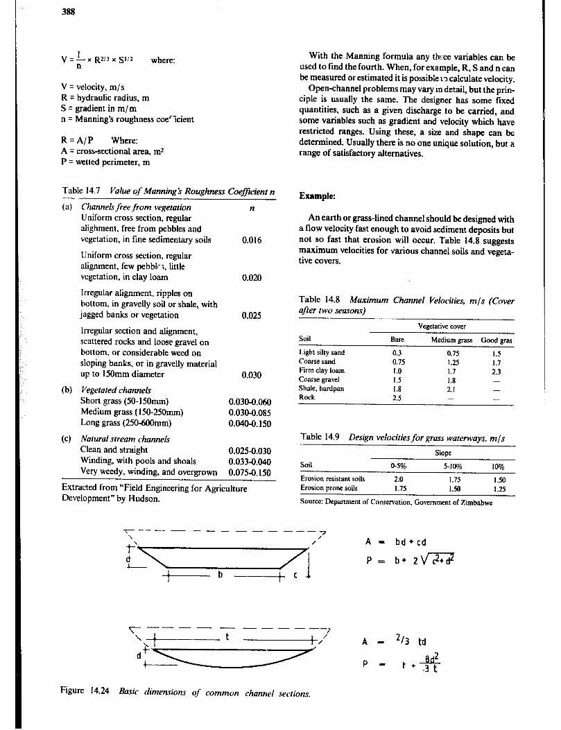
388
V = !.- x R2/3 x 9/2 where: n
V = velocity, m/s R = hydraulic radius, m S = gradient in m/m n = Manning’s roughness coe’icient
R=A/P Where: A = cross-sectional area, m2 P = wetted perimeter, m
Table 14.7 Value c$ ManningS Roughness Coefficient n - (a) Channels free from vegetation
Uniform cross section, regular alighment, free from pebbles and vegetation, in fine sedimentary soils
Uniform cross section, regular alignment, few pebbk <, little vegetation, in clay loam
Irregular alignment, ripples on bottom, in gravelly soil or shale, with jagged banks or vegetation
lrregular section and alignment, scattered rocks and loose gravel on bottom, or considerable weed on sloping banks, or in gravelly material up to 150mm diameter
(b) Vegetated channel Short grass (50- 150mm) Medium grass (ISO-250mm) Long grass (250-6OOmm)
(c) Natural stream channels Clean and straight Winding, with pools and shoals
0.025-0.030 0.033~.040 0.075-O. 150 Very weedy, winding, and overgrown
Extracted from “Field Engineering for Agriculture Development” by Hudson.
n
0.016
0.020
0.025
0.030
0.030-0.060 0.030-0.085 0.04o-o. 150
With the Manning formula any th!:ee variables can be used to find the fourth. When, for example, R, S and n can be measured or estimated it is possible to calculate velocity.
Open-channel problems may vary in detail, but the prin- ciple is usually the same. The designer has some fixed quantities, such as a given discharge to be carried, and some variables such as gradient and velocity which have restricted ranges. Using these, a size and shape can be determined. Usually there is no one unique solution, but a range of satisfactory alternatives.
Example:
An earth or grass-lined channel should be designed with a flow velocity fast enough to avoid sediment deposits but not so fast that erosion will occur. Table 14.8 suggests maximum velocities for various channel soils and vegeta- tive covers.
Table 14.8 Maximum Channel Velocities, mJs (Cover after two seasons)
Vegetative cover
Soil Bare Medium grass Good gras
Light silty sand 0.3 0.75 1.5 Coarse sand 0.75 1.25 1.7 Firm clay loam 1.0 1.7 2.3 Coarse gravel 1.5 I.8 - Shale, hardpan I.8 2.1 - Rock 2.5 - -
Table 14.9 Design velocities for grass waterways, m/s
Slope
Soil O-596 5-l% 1%
Erosion resistant soils 2.0 1.75 I .50 Erosion prone soils 1.75 1.50 1.25
Source: Department of Conservation, Government of Zimbabwe
----------~-----7 “L\/i’ “,I b”“‘:;-gJj?
+---b---+c
---- - ------ ------+,/ A - z/3 td
Figure 14.24 Basic dimensions of common channel sections.

Rural Water Supply and Sanitation 389
For convenience, Figure 14.25 may be used to solve open channel flow problems. For example, assume a chan- nel is to be designed for a firm clay-loam soil with a medium grass cover (200mm) to be established. A flow of 2.0m3/s is the maximum expected and the gradient is approximately O.@~.;m/m. Choose a channel shape and determine a satisfactory size.
From Table 14.7 read a value for roughness coefficient (n) of 0.030 to 0.085; choose 0.04.
From Table 14.8 read 1.7m/ s acceptable velocity.
From Figure 14.25 read 0.30m hydraulic radius.
Arbitrarily choose a parabolic shape.
A = Q/V = 211.7 = 1.18m2
P = A/R = 1.18/0.30 = 3.93m
P = t + y , (assume a value for t of 3.75m)
d*=(P-t)x3t/8 d? = (3.93 - 3.75) x 3 x 3.7518 = 0.25 d q 0.5m
A=2/3td A = 213 x 3.75 x 0.5 = 1.25m2 which is close to the previo:ls A q 1.18mr
In summary, a parabolic-shape channel 3.75m wide and 0.5m deep will be satisfactory.
TURNlh
El.0
-0.20 "2
2 0.4 z -0.15
e 5 =o-10 .-
.u. 3
~~ --*
5 =oo.oo:
E! "
I" o-2 ,z%-- ^. g 0.02 a 0.015
E cr 0.01
Rural Sanitation When dealing with the problems of poor sanitation in rural areas of developing countries, one is tempted to assume that improved technology is the answer and that new latrines will provide the “technological fix”. But technol- ogy alone does not solve anything, for it has been found that new latrines when built are not fully used, and when used do not wipe out diseases that stem from poor srnita- tion. Good sanitation depends on people and how they organize hygiene-related activities. It depends on a large “package”of hygiene measures and latrines are only a part of this package.
Technology does have a part to play and many rural com,munities need has;, technical assistance. Latrines may not always be a practical solution but if they are, they must be carefully designed to match local cultural patterns.
Pit Latrines There are many designs for latrines to be built in areas where more sophisticated sanitary systems are not possi- ble. The simplest design is the pit latrine and there are certain characteristics that are common to the many varia- tions on this design. A latrine should always be dug at least 3Gm downhill from a well if that is the source of the family water supply. However, in areas where the water table is very high the distance should be increased to 200m or more. The latrine should also be at least 1Om from the nearest house or kitchen.
A pit that is a little less than 1 m in diameter is sufficient, but a pit that is a 0.7m by 1.5m oval will provide more convenient space for the person digging. The depth is at
LINE
Figure 14.25 Nomograph for Manning> formula.
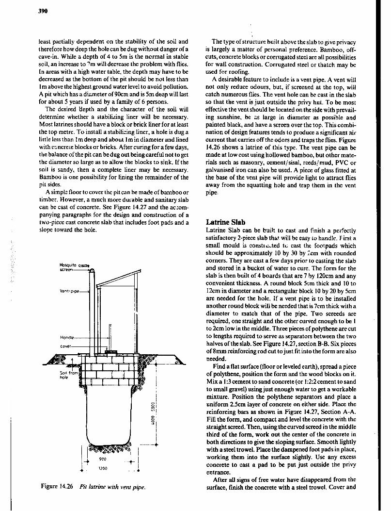
least partially dependent on the stability of the soil and therefore how deep the holecan be dug without danger of a cave-in. While a depth of 4 to 5m is the normal in stable soil, an increase to 7m will decrease the problem with flies. In areas with a high water table, the depth may have to be decreased as the bottom of the pit should be not less than I m above the highest ground water level to avoid pollution. A pit which has a diameter of 90cm and is 5m deep will last for about 5 years if used by a family of 6 persons.
The desired depth and the character of the soil will determine whether a stabilizing liner will be necessary. Most latrines should have a block or brick liner for at least the top metre. To install a stabilizing liner, a hole is dug a little less than 1 m deep and about 1 m in diameter and lined with ccJncrere blocks or bricks. After curing for a few days, the balance of the pit can be dug out being careful not to get the diameter so large as to allow the blocks to sink. If the soil is sandy, then a complete liner may be necessary. Bamboo is one possibility for lining the remainder of the pit sides.
A simple floor to cover the pit can be made of bamboo or timber. However, a much more durable and sanitary slab can be cast of concrete. See Figure 14.27 and the ac:om- panying paragraphs for the design and construction of a two-piece cast concrete slab that includes foot pads and a slope toward the hole.
Figure 14.26 Pit latrine with venr pipe.
The type of structure built above the slab to give privacy is largely a matter of personal preference. Bamboo, off- cuts, concrete blocks or corrugated steel are all possibilities for wall construction. Corrugated steel or thatch may be used for roofing.
A desirable feature to include is a vent pipe. A vent will not only reduce odours, but, if screened at the top, will catch numerous flies. The vent hole can be cast in the slab so that the vent is just outside the privy hut. To be most effective the vent should be located on the side with prevail- ing sunshine, be ns large in diameter as possible and painted black, and have a screen over the top. This combi- nation of design features tends to produce a significant air current that carries off the odors and traps the flies. Figure 14.26 shows a latrine of this type. The vent pipe can be made at low cost using hollowed bamboo, but other mate- rials such as masonry, cement/sisal, reeds/mud, PVC or galvanised iron can also be used. A piece of glass fitted at the base of the vent pipe will provide light to attract flies away from the squatting hole and trap them in the vent pipe.
Latrine Slab Latrine Slab can be bui!t to cast and finish a perfectly satisfactory 2-piece slab that will be easy to handle. F’irst a small mould is consttdded tc cast the footpads which should be approximately 10 by 30 by 2cm with rounded corners. They are cast a few days prior to casting the slab and stored in a bucket of water to cure. The form for the slab is then built of 4 boards that are 7 by 120cm and any convenient thickness. A round block 5cm thick and 10 to 12cm in diameter and a rectangular block 10 by 20 by 5cm are needed for the hole. If a vent pipe is to be installed another round block will be needed that is 7cm thick with a diameter to match that of the pipe. Two screeds are required, one straight and the other curved enough to be 1 to 2cm low in the middle. Three pieces of polythene are cut to lengths required to serve as separators between the two halves of the slab. See Figure 14.27, section B-B. Six pieces of 8mm reinforcing rod cut to just fit into the form are also needed.
Find a flat surface (floor or leveled earth), spread a piece of polythene, position the form and the wood blocks on it. Mix a I:3 cement to sand concrete (or 1:2:2 cement to sand to small gravel) using just enough water to get a workable mixture. Position the polythene separators and place a uniform 2.5cm layer of concrete on either side. Place the reinforcing bars as shown in Figure 14.27, Section A-A. Fill the form, and compact and level the concrete with the straight screed. Then, using the curved screed in the middle third of the form, work out the center of the concrete in both directions to give the sloping surface. Smooth lightly with a steel trowel. Place the dampened foot pads in place, working them into the surface slightly. Use any excess concrete to cast a pad to be put just outside the privy entrance.
After all signs of free water have disappeared from the surface, finish the concrete with a steel trowel. Cover and
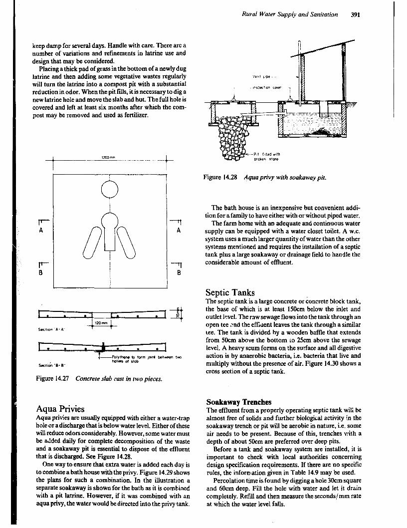
keep damp for several days. Handle with care. There are a number of variations and refinements in latrine use and design that may be considered.
Placing a thick pad of grass in the bottom of a newly dug latrine and then adding some vegetative wastes regularly will turn the latrine into a compost pit with a substantial reduction in odor. When the pit fills, it is necessary to dig a new latrine hole and move the slab and hut. The full hole is covered and left at least six months after which the com- post may be removed and used as fertilizer.
F A
F 0
” OB A 77 B
Sectton ‘A-A’
Sect&n ‘B-B’
between tvm
Figure 14.27 Concrete slab rust in two pieces.
Aqua Privies Aqua privies are usually equipped with either a water-trap hole or adischarge that is below water level. Either of these will reduce odors considerably. However, some water must be added daily for complete decomposition of the waste and a soakaway pit is essential to dispose of the effluent that is discharged. See Figure 14.28.
One way to ensure that extra water is added each day is to combine a bath house with the privy. Figure 14.29 shows the plans for such a combination. In the illustration a separate soakaway is shown for the bath as it is combined with a pit latrine. However, if it was combined with an aqua privy, the water would be directed into the privy tank.
Rural Water Supply and Sanitation 391
Figure 14.28 Aqua privy with soakaway pit.
The bath house is an inexpensive but convenient addi- tion for a family to have either with or without piped water.
The farm home with an adequate and continuous water supply can be equipped with a water closet toilet. A W.C. system uses a much larger quantity of water than the other systems mentioned and requires the installation of a septic tank plus a large soakaway or drainage field to handle the considerable amount of effluent.
Septic Tanks The septic tank is a large concrete or concrete block tank, the base of which is at least 15Ocm below the inlet and outlet level. The raw sewage flows into the tank through an open tee 2nd the effuent leaves the tank through a similar tee. The tank is divided by a wooden baffle that extends from 5Ocm above the bottom io 25cm above the sewage level. A heavy scum forms on the surface and all digestive action is by anaerobic bacteria, i.e. bacteria that live and multiply without the presence of air. Figure 14.30 shows a cross section of a septic tank.
Soakaway Trenches The effluent from a properly operating septic tank tili be almost free of solids and further biological activity in the soakaway trench or pit will be aerobic in nature, i.e. some air needs to be present. Because of this, trenches with a depth of about 50cm are preferred over deep pits.
Before a tank and soakaway system are installed, it is important to check with local authorities concerning design specification requirements. If there are no specific rules, the information given in Table 14.9 may be used.
Percolation time is found by digging a hole 30cm square and f&m deep. Fill the hole with water and let it drain completely. Refill and then measure the seconds/ mm rate at which the water level falls.
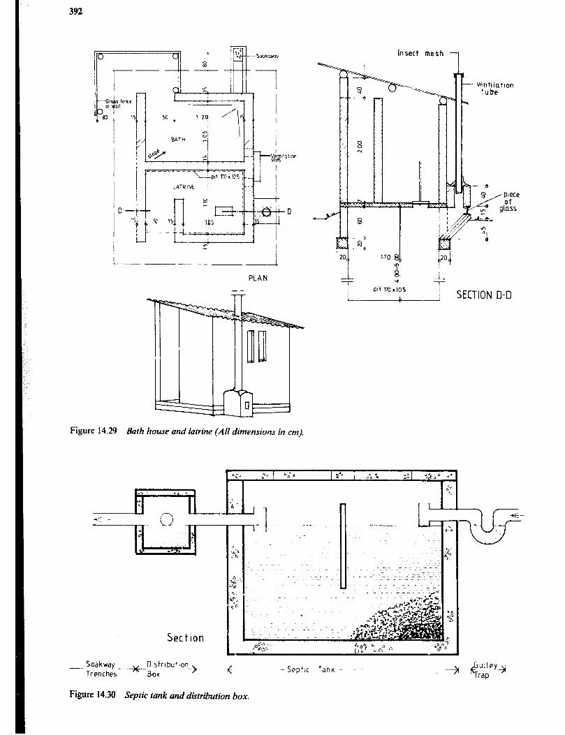
392
Insect mesh -
i / I i
170 EJ
t
20!
$1
4
.-i PLAN
Pl( m x105
L-----&.---l SECTION D-D
Figure 14.29 Bath house and latrine (AN dimensions in cm).
1. . . -.-.~ LL
Section
- Soakway Trenches-
.-+O)strlbu+ion
BOX -?I 6
Septic ttmk and distribution box.
-Septic Tank -
Figure 14.30
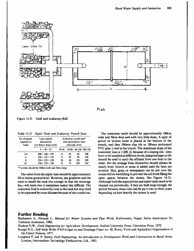
Rural Water Supply and Sanitation 393
Lwse stone fill I
1
Figure 14.31 lbnk and soakawayfield.
Table 14.10 Septic Tank and Soakaway Trench Sizes
No of people Tank indside Soakaway trench (m)* regularly in dimensions with percolation rates
home (cm below drain level) (seconds/ mm)
LxWxD I&30 30-60 60-100 100-140
23 200~100~150 IO 30 60 100 6 250x 125 x 150 15 45 90 150 II 250x125=150 20 60 120 200
10 250x ISOX 150 25 75 150 250
*Trenches should be 1Olkm wide and 5Ocm deep.
The outlet from the septic tank should be approximately 50cm below ground level. However, site gradients and the need to install the tank low enough so that the sewerage l&s will drain into it sometimes makes this difficult. The soakaway field is ordinarily close to the tank but may need to be separated by some distance because of site conditions.
Plan
The soakaway tenth should be approximately 1OOcm wide and 5Ocm deep and with very little slope. A layer of gravel or broken stone is placed in the bottom of the trench, and then 1OOmm clay tile or IOOmm perforated PVC pipe is laid in the trench. The maximum slope of the soakaway lines is 1:200. If, because of a sloping site, lines have to be installed at different levels, leakproof pipe or tile should be used to carry the effluent from one level to the other, but the seepage lines themselves should always be nearly level. Gravel or stone is added until the lines are covered. Hay, grass or newspapers can be put over the stones before backfilling to prevent the soil from filling the open spaces between the stones. See Figure 14.31. Although both the aqua privies and septic tanks need to be cleaned out periodically, if they are built large enough, the period between clean-outs can be up to two to three years depending on how heavily the system is used.
Further Reading Bachmann A., Nirman J., Manual for Water Systems and Pipe Work, Kathmandu, Nepal, Swiss Association for Technical Assistance. 1980. Hudson N.W., Field Engineering for Agriculture Development, Oxford University Press, Clarendon Press, 1975. Koegel R.G., Se&Help Wells, FAO Irrigation and Drainage Paper no. 30, Rome, Food and Agriculture Organization of
the United Nations, 1977. Longland F. (ed. P. Stem), Field Engineering: An Introduction to Development Work and Construction in Rural Areas,
London, Intermediate Technology Publications, Ltd., 1983.

394
Mann H.T., Williamson D., Water Treatment and Sanitation. Simple Methods for Rural Areas, London, Technology Publications Ltd., 1976.
Nissen-Petersen, Rain Catchment and Water Supply in Rural Africa: A Manual, London, Hodder and Stoughton, 1982. Pacey A., Rural Sanitation: Planning and Appraisal, An Oxfam Document, London, Intermediate Technology
Publications Ltd., 1980. SKAT, Manualfor Rural Water Supply, with Many Detailed ConstructionalScale-drawings, Publication No. 8, St. Gallen,
%i;z Centre for Appropriate Technology, SKAT, 1980. VI i A, Using Water Resources, Mt. Rainier, M.D., Volunteers in Technical Assistance, 1977. Waterhouse J., Water Engineering for Agriculture, London, B.T. Batsford Ltd., Academic and Educational, 1982. Watt S.B., A Manual on the Hydraulic Ram for Pumping Water, London, Intermediak Technology Publications Ltd.,
1977. Watt S.B., Ferrocement Water Tanks, and Their Construction, London, Intermediate Technology Publications Ltd., 1978. Watt S.B., Wood W.E., Hand-dug Wells and Their Construction, London, Intermediate Technology Publications Ltd.,
197.8.

Appendix I
Appendix I. Sl-base units
Appendix 1: 1 The seven base units in the Inrernarional Swem of Clnits (SO
Quantity Name of Symbol base SI Unit
Length metre MiiSS kilogram Time second s Electric current ampere A Thermodynamic temperature kelvin K Amount of substance mole mol Luminous intensity candela cd
.4ppendis I: 2 Some derived SI-unirs with their symbol/derivation
common Quantity symbol Unit Symbol Derivation
Term Term
Lmgth a, b, c metre m Sl-base unit Area A square metre Volume V cubic metre ;: Mass
P &o,
kilogramme kg SI-base unit Density kilogramme per cubic metre kg/ m3 Force F Newton N IN = lkgm/sz Weight force W Newton N 9.80665N q I kgf Time t second S SI-base unit Velocity V metre per second m/s Acceleration a meter per second per second m/s2 Frequency (cycles per second) f Hertz Hz lHz= lc/s Bending moment Newton metre Nm Pressure P”F
u (sigma) Newton per square metre N/m? IMN/mZ = 1N/mm2
Stress Newton per square metre N/d Work, energy W Joule J 1J = INm Power Watt W 1W = lJ/s Quantity of heat
i Joule
Thermodynamic temperature Kelvin ;: SI-base unit Specific heat capacity Joule per kilogram degree Kelvin J! kg x ’ K Thermal conductivity it Watt per metre degree Kelvin W/mx’K Coefficient of heat U Watt per square metre Kelvin w/m2 x “K
Appendix I: 3 Multiples and sub multiples of SI- Units common(l: used in construc!ion theory
Factor Prefix Symbol
Prefix in brackets should be avoided.
IOh 103 (102 (10 (IO ' (102 IO 3 IO”
mega M kilo k hecto h) deka da) deci d) centi c) milli m micro U
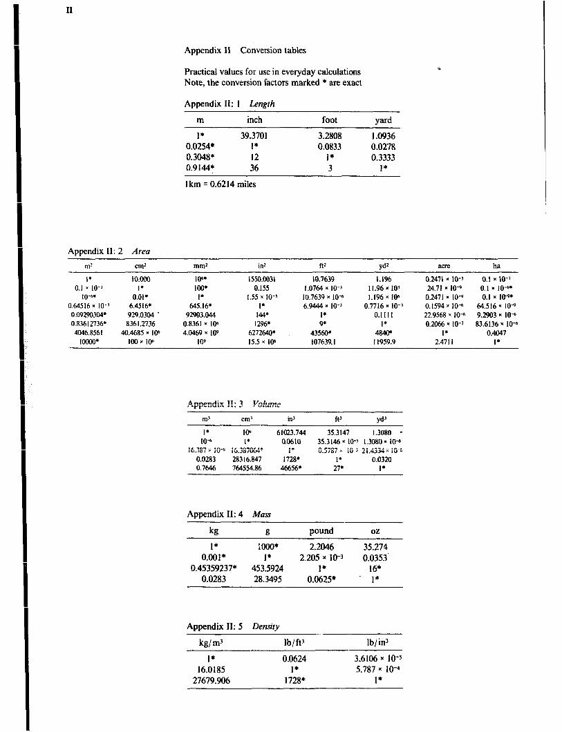
II
Appendix II Conversion tables
Practical values for use in everyday calculations Note, the conversion factors marked * are exact
Appendix II: I Length
m inch
1* 39.3701 0.0254* 1* 0.3048* 12 0.914J.V 36
foot yard
3.2808 1.0936 0.0833 0.0278
1* 0.3333 3 1*
I km = 0.6214 miles
Appendix II: 2 Area
m!
I* 0.1 ” 10-j IO”’
0.64516* IO-' 0.09290304* 0.X3612736* 4046.8561 lOOMI*
cm2
10.000 1’
0.01 l
6.4516* 929.0304 . 8361.2736
40.4685 * lob IOO~IW
id ft'
106. 100* I*
C45.16* 92903.044 0.8361~ Ioh 4.0469 x IO9
I09
1550.0031 0.155
1.55 x IO-' I* 144* l296*
62721X0* 15.5 K 10"
10.7639 1.1% 1.0764 x IO-' 11.96 * 10' 10.7639 x IO" I.196 x 106 6.9444 x IO-" 0.7716 x IO-'
1* 0.1111 9* I*
43560. 4&w 107639.1 11959.9
Yd’ acre
0.2471 1 lo-' 24.71 z+ IO+ 0.2471~ IO+ 0.1594 x 10⁴ 22.9568 = IO-n 0.2066 x IO-'
I* 2.4711
ha
0.1 x IO-' 0.1 = IO** 0.1 n KY*
M4.516~ IO-9 9.2903 N IO-6 83.6136~ IO+
0.4047 I*
Appendix II: 3 Volume
rn3 cm3 in' ft' Yd'
I* IO 61023.744 35.3147 1.3080 - IO-3 1. 0.0610 35.3146 x IO-' 1.3080~ IO-6
16.387~ IO" 16.387064' I* 0.5787 x IO-' 21.4334~ IO" 0.0283 28316.847 1728, I* 0.0320 0.7646 764554.86 46656, 27* I*
Appendix II: 4 Mass
kg g pound 02
1* :ooo* 2.2046 35.274 0.001* 1* 2.205 x 10-r 0.0353.
0.45359237* 453.5924 1* 16* 0.0283 28.3495 0.0625* l*
Appendix II: 5 Density
kg/ m3 lb/ ft3 lb/ in3
1* 0.0624 3.6106 x 10⁻⁵ 16.0185 1* 5.787 x IO-4
27679.906 1728* 1*
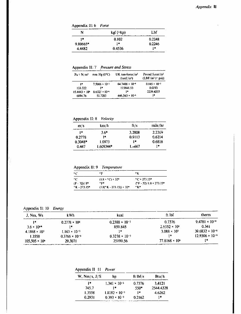
Appendix II
Aooer,dix II: 6 Force
N kgf (=kp) Lbf
I* 0.102 02248 9.80665* 1* 0.2246 4.4482 0.4536 I*
Appendix 11: 7 .Pressure and Stress -- - Pa = N/m” mm Hg (0°C) UK ton-force/in* Pound force/in2
(lonf/iG) (LBF/in* (7 psi))
I* 7.5006 x IO-’ 64.7488 x IO-” 0.145 x 10-j 133.322 I* 115841.53 0.0193
15.4443 x 10⁶ 8.632’: x 10” I* 2239.4237 6894.76 51.7283 446.543 x IO” I*
Appendix II: 8 Velocity
m/s km/h ft/s mile / hr
1* 3.6* 3.2808 2.2369 0.2778 1* 0.9113 0.6214 0.3048* 1.0973 1* 0.6818
0.447 I .609344* 1 .-t667 1*
Appendix II: 9 Temperature
OC “F “K
“C (1.8 a “C) + 32* OC + 273.15, (F. 32)1.8* OF* (“F - 32)/ 1.8 + 273.15’ “K - 273.15* (1.8(°K-273.15))+ 32; OK*
Appendix II: 10 Energ)*
J. Nm. Ws kWh kcal ft Ibf therm
I* 0.2778 x 10⁶ 0.2388 x IO-3 0.7376 9.4781 x lo* 3.6 x lW* I* 859.845 U552 x 106 0.341
4.1868 x IO-’ 1.163 x IO-3 I* 3.088 x 103 39.6832 x 1O-6 I .3558 0.3766 x IO-6 0.3238 x IO-3 I* 12.8506 x IO+
105,505 x 10” 29.307 I 25 199.56 77.8 168 x IO6 1*
Appendix II ! I Power
W, Nm/s, J/S hp ft Ibf/s Btu/ h
1* 1.341 x IO-3 0.7376 3,412l 745.7 I* 550* 2544.4328 I .3558 1.8182 x IO-3 1* 4.6262 0.293 1 0.393 x IO-3 0.2162 I*
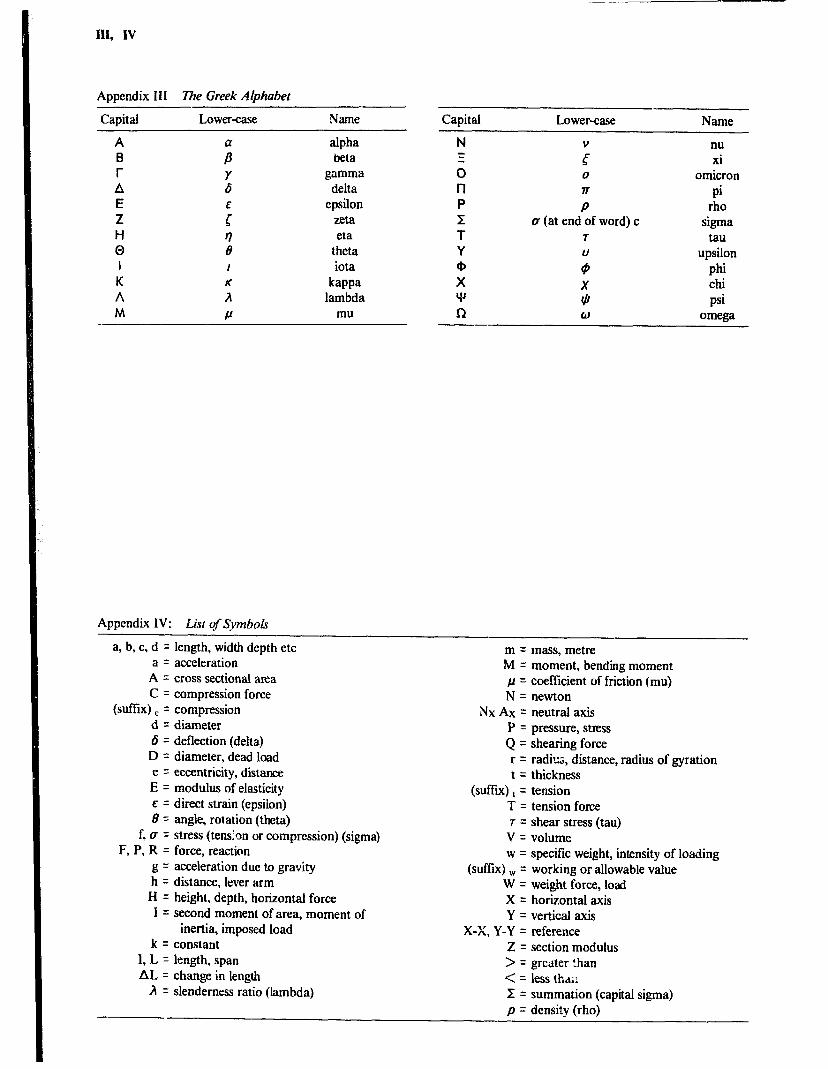
Appendix I11 The Greek Alphabet
Capital Lower-case Name
A B r A E Z H 0 I K A M
alpha beta
gamma delta
epsilon zeta eta
theta iota
kappa lambda
mu
Capital Lower-case Name
0
a
P CT (at end of word) c
7
s X (// w
nu xi
omicron
Pi rho
sigma tau
upsilon phi Chi
psi omega
Appendix IV: List of $vmbols
a, b, c, d = length, width depth etc a = acceleration
A = cross sectional area C = compression force
(suffix) E = compression d = diameter 6 = deflection (delta) D = diameter, dead load e = eccentricity, distance E = modulus of elasticity E = direct strain (epsilon) B = angle, rotation (theta)
f, u = stress (tensIon or compression) (sigma) F, P, R = force, reaction
g = acceleration due to gravity h = distance, lever arm H = height, depth, horizontal force I = second moment of area, moment of
inertia, imposed load k q constant
I, L q length, span AL q change in length
A = slenderness ratio (lambda)
m = mass, metre M = moment, bending moment j2 = coefficient of friction (mu) N = newton
NxAx= neutral axis P = pressure, stress Q = shearing force r = radius, distance, radius of gyration t q thickness
(suffix) , = tension T = tension force r = shear stress (tau)
V = volume w q specific weight, intensity of loading
(suffx) w = working or allowable value W q weight force, load X = horizontal axis Y = vertical axis
X-X, Y-Y = reference Z q section modulus > = greater than < = less tha,: r q summation (capital sigma) p = density (rho)
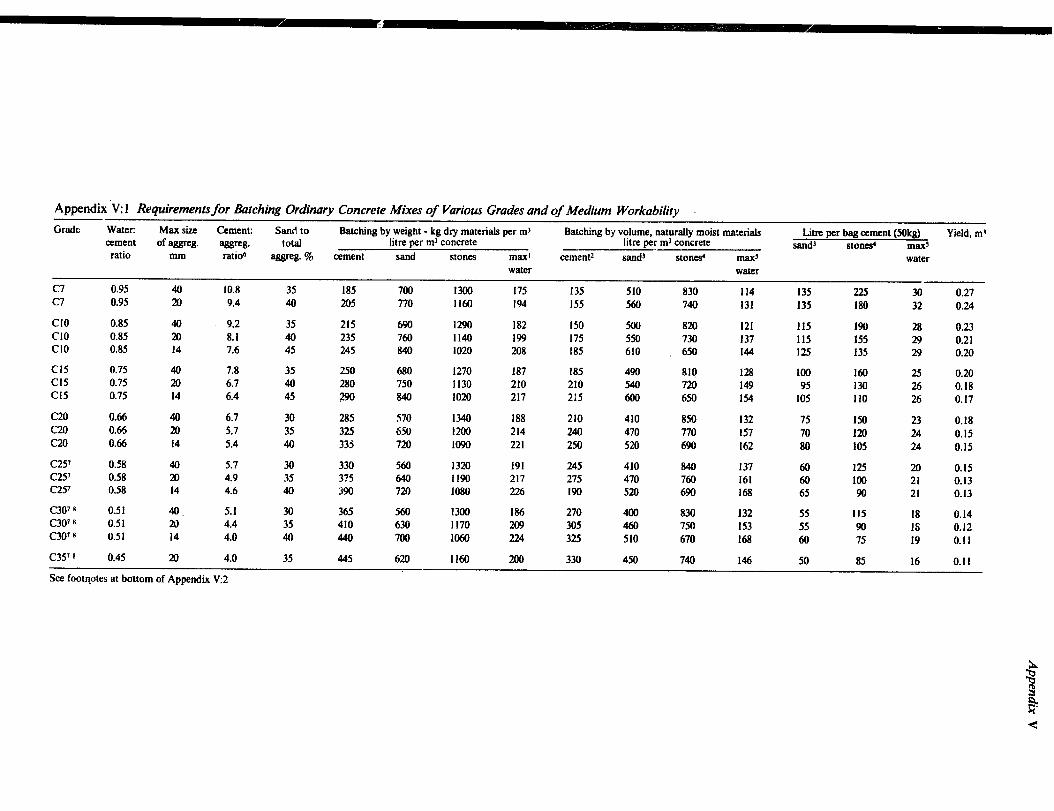
Appendix ‘V: I Requirements for Batching Ordinary Concrete Mixes of Various Grades and of Medium Workability
Grade Water: Max size Cement: Sand to Batching by weight - kg dry materials per ml Batching by volume, naturally moist materials Litre per bag cement (5Okg) Yield, rn* cement of aggrcg. aggrrg. total litre per ml concrete litre per rnJ concrete
ratio sand’ StOlhd
mm ratio6 maxs
aggreg. 7% cement sand stones maxl cement2 sand’ stone ma.+ water water water
c7 0.95 40 10.8 35 185 700 1300 175 c7
135 0.95
510 830 20 9.4
114 135 225 40 205 770
30 0.27 1160 194 155 560 740 131 135 180 32 0.24
Cl0 0.85 40 9.2 35 215 690 1290 182 Cl0
150 500 0.85
820 m 8.1
121 40 23.5
115 190 28 760 1140
0.23 199
Cl0 175
0.85 550 730
14 7.6 137
45 245 115 155
840 29
1020 208 0.21
185 610 650 144 125 135 29 0.20
Cl5 0.75 40 7.8 35 250 680 1270 187 Cl5
185 0.75
490 81tJ 20 6.7 40
128 280
100 750
160 25 1130
0.20 210
Cl5 210
0.75 540 720
14 6.4 149
45 95
290
130 840
26 1020 217
0.18 2!5 600 650 154 105 110 26 0.17
C20 0.66 40 6.7 30 285 570 1340 188 210 c20
410 850 0.66 20 5.7
132 75 35
I50 325
23 0.18 650 1200 214 240
c20 470 770
0.66 157
14 5.4 70 Irn
40 33s 24
720 0.15
1090 221 250 520 690 162 80 105 24 0.15
C25’ 0.58 40 5.7 30 330 560 1320 191 C25’
245 0.58
410 840 20
137 4.9 35
60 315
125 20 640 1190 217
0.15
C25’ 275
0.58 470 760
14 4.6 40 161 60 loo 21 0.13
390 720 1080 226 190 520 690 168 65 90 21 0.13
C307 B 0.51 4. 5.1 30 365 560 1300 186 270 C307 8
4cMl 0.51 a,
830 4.4
132 35
55 410 630
115 18 1170 209
0.14 305
c307 8 460
0.51 750
14 153
4.0 55 90 18
40 440 700 1060 224 0.12
325 510 670 168 60 75 19 0.11
c357 8 0.45 20 4.0 35 445 6rn 1160 ux) 330 450 740 146 50 85 16 0.11
See footqotes at bottom of Appendix V:2
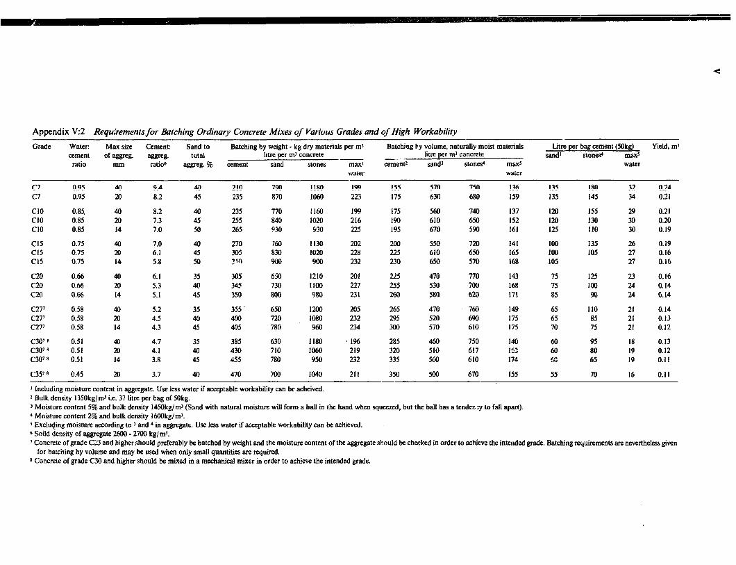
Appendix V:2 Requ;iements for Batching Ordinary Concrete Mixes of Various Grades and of High Workability
Grade Water: Max size Cement: Sand to Batching by weight - kg dry materials per rn3 Batching by volume, natural!y moist materials Litre per bag cement (50kg) Yield, m3 cement of ws3w. aggre8. total litre per rn3 concrete litre per rn3 concrete sand’ stone+ m&lx> _._ ratio mm ratio6 apgrep.% cement sand stones maxi cement* sand’ stones+ maxs water
water water
C? c7
0.95 0.95
Cl0 0.85. Cl0 0.85 CIO 0.85
Cl5 Cl5 Cl5
0.75 0.75 0.75
C20 c20 c20
0.66 0.66 0.66
c27'T 0.58 C27' 0.58 c277 0.58
C3O'B CM7 8 C3078
c357 8
0.51 0.51 0.51
0.45
40 20
40 20 14
40 20 14
40 20 14
40 20 14
40 20 14
20
9.4 8.2
8.2 7.3 7.0
7.0 6.1 5.8
6.1 5.3 5.1
5.2 4.5 4.3
4.7 4.1 3.8
3.7
40 45
40 45 50
40 45 50
35 40 45
35 40 45
35 40 45
40
210 790 235 870
235 255 265
770 840 930
270 760 305 8M ?Wl 900
305 345 350
650 730 800
355 650 400 720 405 780
385 630 430 710 455 780
470 700
1180 199 1060 221
1160 199 1020 216 930 225
1130 202 1020 228 900 232
1210 201 1100 227 980 231
L?llo m5 lo80 232 960 234
1180 1% 1060 219 950 232
1040 211
155 570 750 136 135 175 630 680 159 135
175 560 740 137 120 190 610 650 152 120 195 670 590 161 I25
200 550 720 141 loo 225 610 650 165 100 230 650 570 168 105
225 470 770 255 530 700 260 580 620
75 125 23 0.16 75 100 26 0.14 85 90 24 0.14
265 295 304
470 520 570
460 510 560
500
760 690 610
65 110 21 65 85 25 70 75 21
285 320 335
750 617 610
350 670
143 168 171
149 175 175
140 15: 174
155
60 60 5s
55
180 145
155 130 110
135 105
95 18 80 19 65 19
70 16
32 0.24 34 0.21
29 0.21 30 0.20 30 0.19
26 0.19 27 0.16 27 0.16
0.14 0.13 0.12
0.13 0.12 0.11
0.11
1 Including moisture content in aggregate. Use less water if acceptable workability can be acheived. * Bulk density 1350kgjmJ i.e. 37 iitre per bag of Mkg. 3 Moisture content 5% and bulk density !45Okg/rn’ (Sand with natural moisture will form a ball in the hand when squeezed, but the ball has a tendec -y to fa!l apart). 4 Moisture content 2% and bu!k density 16OOkg/m’. 5 Exc!u$ng moisture according to 3 and 4 in -gate. Use less water if acceptable workability can be achieved. 6 Soi!d density of aggregate 2600 - 2700 kg/&. 7 Concrete of grade CZ and higher should preferably be batched by weight and the moisture content of the aggregate should bc checked in order to achieve the intended grade. Batching requirements are nevertheless giwn for batching by volume and may be used when only small quantities are required.
* Concrete of grade C30 and higher should be mixed in a mechanical mixer in order to achieve the intended grade.

Appendix V
Appendix V: 3 Dimensions and Properties of Steel I Beam-s
Nominal Mass size per
metre
Depth Width of of
section section D B
Thickness Web Flange
t T
Radius Depth Area Koot Toe between of
rl r2 fillets section d
mm kg mm mm mm mm mm mm mm cm2
254x 203 81.85 254.0 254x 114 37.20 254.0
203 x 152 52.09 203.2 203 x 102 25.33 203.2
178x 102 21.54 177.8
152x 127 37.20 152.4 152x 89 17.09 152.4 152x 76 17.86 152.4
127x 114 29.76 127.0 127 x 114 26.79 127.0 127 x 76 16.37 127.0 127 x 76 13.36 127.0
114x 114 26.79 114.3
102 x 102 23.07 101.6 102x 64 9.65 101.6 102x 44 7.44 101.6
89x 89 19.35 88.9
76x 76 14.67 76.2 76~ 76 12.65 76.2
203.2 10.2 19.9 19.6 114.3 7.6 12.8 . 12.4
152.4 8.9 16.5 15.5 101.6 5.8 10.4 9.4
101.6 5.3 9.0 9.4
127.0 10.4 13.2 13.5 88.9 4.9 . 8.3 7.9 76.2 5.8 9.6 9.4
114.3 , 10.2 11.5 9.9 114.3 7.4 11.4 9.9 76.2 5.6 9.6 9.4 76.2 4.5 7.6 7.9
114.3 9.5 10.7 14.1
101.6 9.5 10.3 11.1 63.5 4.1 6.6 6.9 44.4 4.3 6.1 6.9
88.9 e 9.5 9.9 11.1
80.0 8.9 8.4 9.4 76.2 5.1 8.4 9.4
9.7 6.1
7.6 3.2
3.2
6.6 2.4 4.6
4.8 5.0 4.6 2.4
3.2
3.2 2.4 3.3
3.2
4.6 4.6
166.0 104.4 199.2 47.4
133.2 66.4 161.0 32.3
138.2 27.4
94.3 47.5 117.7 21.8 111.9 22.8
79.4 37.3 79.5 34.1 86.5 21.0 94.2 17.0
60.8 34.4
55.1 29.4 73.2 12.3 74.7 9.5
44.1 24.9
38.0 19.1 37.9 16.3
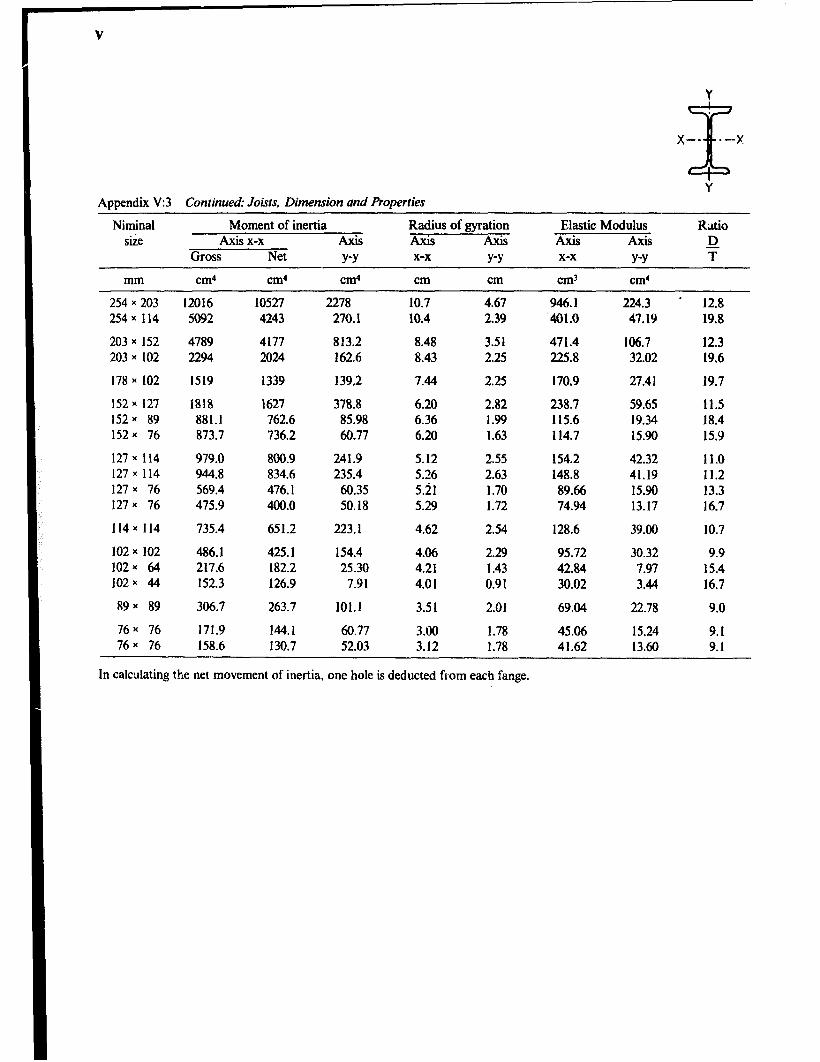
Y
X --
x
--x
Y Appendix V:3 Continued: Joists, Dimension and Properties
Niminal size
Moment of inertia Radius of gyration Elastic Modulus Ratio Axis x-x AXiS Axis Al& Axis Axis D
Gross Net Y-Y x-x Y-Y x-x Y-Y T
mm cm4 cm4 Cd cm cm cm? cm4
254 x 203 254 x 114
203 x 152 203 x 102
178 x 102
152 x 127 152 x 89 152x 76
127 x 114 127 x 114 127 x 76 127x 76
114 x 114
102 x 102 102 * 64 102x 44
89 x 89
76 x 76 76 x 76
12016 5092
4789 2294
1519
1818 881.1 873.7
979.0 944.8 569.4 475.9
735.4
486.1 217.6 152.3
306.7
171.9 158.6
10527 4243
4177 2024
1339
1627 762.6 736.2
800.9 834.6 476.1 400.0
651.2
425.1 182.2 126.9
263.7
144.1 130.7
2278 270.1
813.2 162.6
139.2
378.8 85.98 60.77
241.9 235.4
60.35 50.18
223.1
154.4 25.30
7.91
101.1
60.77 52.03
10.7 10.4
8.48 8.43
7.44
6.20 6.36 6.20
5.12 5.26 5.21 5.29
4.62
4.06 4.21 4.01
3.51
3.00 3.12
4.67 2.39
3.51 2.25
2.25
2.82 1.99 1.63
2.55 2.63 1.70 1.72
2.54
2.29 1.43 0.91
2.01
1.78 1.78
946.1 ‘401.0
471.4 225.8
170.9
238.7 115.6 114.7
154.2 148.8 89.66 74.94
128.6
95.72 42.84 30.02
69.04
45.06 41.62
224.3 ’ 12.8 41.19 19.8
106.7 12.3 32.02 19.6
27.41 19.7
59.65 11.5 19.34 18.4 15.90 15.9
42.32 11.0 41.19 11.2 15.90 13.3 13.17 16.7
39.00 10.7
30.32 9.9 7.97 15.4 3.44 16.7
22.78 9.0
15.24 9.1 13.60 9.1
In calculating the net movement of inertia, one hole is deducted from each fange.

PSYCHROMETRIC CHART NORMALTEMPERATURES
SI METRIC UNITS
RarnmPtrie PIPccllrTz 101 325 IcPa 26
--.-...-_..- . .----.- .- ..--- . . . - 25 --- ~-. .-.
SEA LEVEL 24
23
22
-io \
6 ia
\ ia
\
i 4a 45 50 55
Dry Bulb Tampwaturs ‘C \ 0.75 0.80 0.85 0 90
Below O’C Prppenies and Enthalpy Oev~alton Lines Are For Ice Volume &kg Dry Air
Rev. 6.81
Copyright :Carricr Cotpatrcio I” 1979 Cat. NO. 794.001 Pnntrd in U.S.A.
0.36
I 0.00
\.45
,a.50
:a.55
A.60
pm
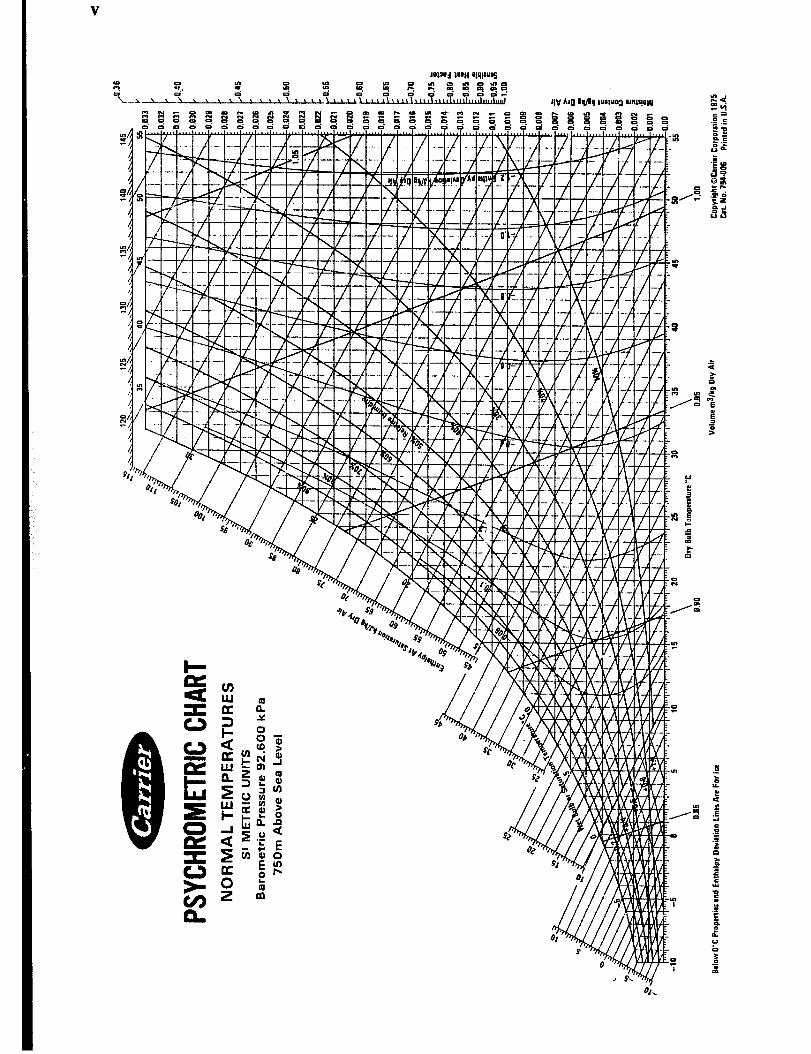

A
‘!O
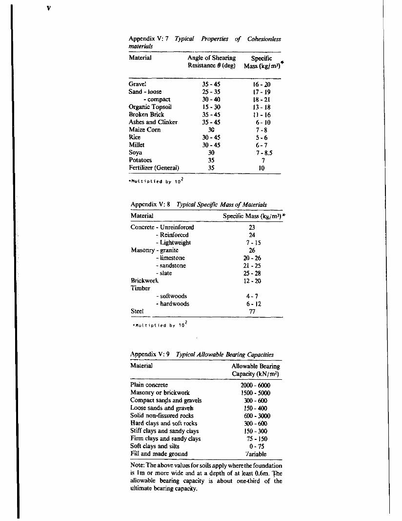
V
Appendix V: 7 i’jpical Properties of Cohesionless mate&h
Material Angle of Shearing SpXifiC Resistance 6 (deg) Mass (kg/ ml)*
Grave: 35-45 16-20 Sand -loose 25 -35 17- 19
- compact 30-40 18-21 Organic Topsoil 15-30 13-18 Broken Brick 35-45 ll- 16 Ashes and Clinker 35-45 6-10 Maize Corn 3G 7-8 Rice 30-45 5-6 Millet 30-45 6-7 Soya 30 7 -8.5 Potatoes 35 7 Fertilizer (General) 35 10
*Multiplied by TO2
Appendix V: 8 Typical Specific Mass of Materials
Material Specific Mass (kg/m3) *
Concrete - Unreinforced 23 - Reinforced 24 - Lightweight 7-15
Masonry - granite 26 - limestone 20-26 - sandstone 21 -25 - slate 25-28
Brickwork 12-20 Timber
- softwoods 4-7 - hardwoods 6-12
Steel 77
*Mu(tip\ied by 102
Appendix V: 9 Typical Allowable Bearing Capacities - Material Allowable Bearing
Canacitv (kN/m*)
Plain concrete Masonry or brickwork Compact sands and gravels Loose sands and gravek Solid non-ffisurcd rocks Hard clays and soft rocks Stiff clays and sandy clays Firm clays and sandy clays Soft clays and silts Fill and made ground
2GOG-6000 15OG-5000 300-600 150-400 lm-300G 300-600 150-300 :5- 150 o-75
‘Jariable
Note: The above values for soils apply where the foundation is lm or more wide and at a depth of at least 0.6m. The allowable bearing capacity is about one-third of the ultimate bearing capacity.

Appendix V
Appendix V: 10 Typical Strength Properties and Allow- able Stresses (NJmmz)
Mild-Steel Sections Youngs Modulus (E) Tension or compression stress
in bending Axial tension
Bearing Shear
206,009
155 - 165 155 (depends on
slenderness ratio) 190 115
Mild-Steel Rivets and Bolts Axial tension: rivets 100
bolts 120 Shear: rivets 90-100
bolts 80 Bearing (double shear): rivets 265 - 315
bolts 200
Timber (Green > 18% Moisture) Softwoods Hardwood (values in thousands)
Young Modulus (E) 4- 12 5 - 19 Bending or tension Parallel to grain 3- 11 4 - 27
Compression pa&led to grain 21/?-8ti 4 - 27 Compression perpendkular to grain vi- 1% l$$-5%
Shear parallel to grain %- 1% 2/-3X
Extracts from B.S. 499 and C.P. 112 are reproduced by permission of the British Standards Institution. Complete copies of the standard can be obtained from them at Linform Wood, Milton Keynes, MK14 6LE, England.
P
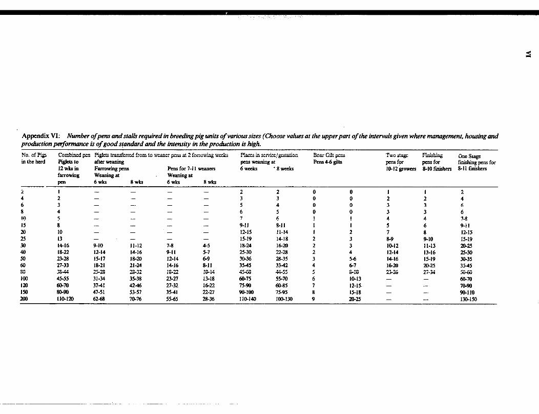
Appendix VI: Number ofpens and stalls required in breeding pig units of various sizes (Choose vaIus at the upper part of the inter& given where management, housing and production performance ir of good s!an&rd and the intensity in the proakction b high.
No. of Pigs Combined pen Pig&s transferred from to weaner pens at 2 forrowing weeks Place3 in servicc!gestation EhlrGiltps Two stage Finishing in the herd Piglets to llfterwellning
ol=stagc pm8 weiuling a! Pens 4-6 gilts
12wksin pens fpr pens for ftihing pens for
Farrowing pens Pens for 7-t I wxners 6 weeks ‘EWE&S llLL12 growem 8-10 finishers 8-I I finishers farrowing weaning at weaningat
pen 6WkS 8Wk3 6wks 8WkS
2 1 - - - - 2 2 0 0 I I 2 4 2 - - - - 3 3 0 0 2 2 4 6 3 - - - - 5 4 0 0 3 3 6 8 4 - - - - 6 5 0 0 3 3 6 10 5 - - - - 7 6 I I 4 4 7-a 15 a - - - - 9-11 8-l I 1 I 5 6 9-11 20 10 - - - - 12-15 I l-14 I 2 7 8 12-15 25 13 - - - 15-19 M-18 2 3 8-9 9-10 15-19 30 M-16 9-10 II-12 7-8 4-5 18-24 16-20 2 3 IO-12 II-13 20-25 40 M-22 12-14 M-16 9-11 5-7 25-30 22-28 2 4 12-14 1316 25-30 50 23-B 15-17 18-m 12-14 6-9 30-36 28-35 3 5-6 M-16 15-19 30-35 60 27-33 18-21 21-24 M-16 8-11 3545 3342 4 6-7 M-20 m-25 3M5 80 3844 25-m 28-32 18-22 IO-14 4560 44-55 5 8-10 23-26 27-34 5w50 100 45-55 31-34 35-38 23-27 13-M 60-75 55-70 6 IO-13 60-70 120 60-70
-
3741
-
4246 27-32 M-22 75-90 a-85 7 12-15 - 70-90 Iu1 8o-!m 47-51
-
53-57 3541 22-27 w-100 75-95 8 15”lS 90-110 200 m4rn
-
62-68
-
70-76 5545 28-36 110-140 m-130 9 20-25 - - 130-150

Index A Abreast parlour 274,276 Acryiis 65 Action forces 71 Adobe blocks 41 Aggregate 49.50 Air distribution 250
inlet(s) 58, 59 208 movements 260 flow meters 237 flow resistance 232
Alley widths 266 Allowable compressive stress concrete Aluminium sheets 157 Ambient temperature 193 Angle of repose 1 I7 Angles: seeting out of 18 Animal bevaviour 257 Aqua privy 391 Arch 84 Artiliciai drying 229,230 Asbestos cement 61
cement sheets I56 Askew loads 94 Auction ring 370 Auger conveyors 246 Automatic drinkers 280
B Bag storage 241 Ballast 49 Bamboo 33
joints 34 preservation 35 shingla I60 wall I41
Batch driers 234 Beams a4
equations 97 loading cases 96 nactions 74
Beaufort scale of winds 120 Beef cattle 262 Bending moment 76.97 stress 93
Bituminous oroducts 66 Biil of quantities 10. 181, 182 Binders 46 Bins 238 Blockboards, laminboards 33 Blockmaking 41, Blocks 57 Boards 32.33 Bolt joints 110 Bolts 64 Boning rod 22 Bricks 133
making 44 -walled silo 239
Bridges 355 Buckling of columns 98 BuiIders’s square 21 Building hfctihne 185
legislation 180 module 179 production process 175 regulations 180
Butt joints 110
C Cable 83 Calf shed 268,269 Cattle crush 368
dips 282,283 guards 266.364 housing 263 races 367
Cattle yards 367 Cement 47
mortar 59 phtster 60
Centrifugal blower 207 fans 205 DUrnDS 378
Chain s&eying 20 Channel flow 387 Chickens, recommended space 301 Chipboard 33 Chitting stores 252
105 Circuits 172 Claddinas 140 Clamp -248 Clay 37
blocks 44 silo 238
Cleaning of crops 237 Climatic factors 260 coal-tar 31 Cob 40 Coir waste 35 Colinear forces 7 I Collecting yard 277 Columns 83,98, 103 Compo mortar 59 Compressive stress 80
stress in concrete 103 Concrete 48
blocks 57, 133 design 103, 105 columns 103 compaction 53 compressive strength 50 curing 55 finishes 56 foundations I26 ingredients 49.5 I joints 55 mixing 52 workability 51
Condensation 244 Connections I10
for steel frames 113 Construction methods 175 Continuous beams 96 Continuous-flow driers 234 Contour lines 21 Contracts 189 Conveyors 246 Coolina tcchniaues 210 CopIan& forces 69 Corrosion 62 Corrugated rooting 154 Cost estimate 10 Costing 183 couples 74 Creosote 31 Cross section 88
stave 18 Culvert construction 355
D Dagga plaster 60 Dairy: goats 318 Dalton\ law 199 Dcad10ads 82 tm Deep-bedded sheds 266 Deep layer drying 23 1 Deep litter system 303 Dcepwell turbme pumps 380 Deflection 92,97 Deformation 81 Density of conctete 103, 105 Density of materials 121 Design criteria constructions 93
Design criteria of teams 89 of coucrete 102, 105
Design of channels 387 of driers 233 ofdwellings 342 of feed troughs 290, JO1 of load 107 of members 84 of purlin 94 of roads 349 of stress a2 oftimber 101 of ventilation ma, 260
Double-pitched roof 147 Drainage 122,160 Drains 351 Driers 234 Drifts 353 Diaphragm pumps 390 Dimemions for feed trough 277
of frcestaus 266 tie-stall 267 of vehicles turning 358
Diistreas a4 Divided contract 187 Documentation of a building project 5 Doors 162 Double-lap joint I10
E Earthing 172 Farthquakes 215 Earth foundation 126
road 358 roof 146 track 350
EaentricaUy loaded 103 Economic plan 218 Egg cooling & handling 323.3 13 Elasticity 8 1 Electrical motor3 I73
supply 171 Elevation(s) 4.9 Elevator 246 Enthalpy 200 Environmental factors 263
requirements 259 Equilibriant 70 Equilbrium moisture content (EMC) 227 Evaporative cooling 201 Evaporator size 250 Exhaust ventilation system 2tM
F facings 140 Factor of safety 82 Fans 204 Fancapacities 233
laws 240 location 208
Farm dwellings 337 dwellings improvements 340
Farrowing pers 286,295 Feeding equipment 275,277,298.310,312 Feed handlimt 280
mquirert&s 397.31 I storage 297 trough 278,297
Fences 359 Fencing 27 Ferr&ment 60 Field book 18.20 Field gate 365. Fii protection 223 Fibre-reinforcement 60 Flat roof 2145 Floor drying system 232

Floors 140 Flow diagram 221 Footbaths 283
Footing and foundation 123 Force 68
triangle 70 Formwork; concnte 55.56 Foundations I22
Foundation plan 8 walerproofing 129
Frame walls 139 Frames 108
Free-body diagram 70 FreestalLs 266 Friction losses in pipes
384
Fruit and vegetables 253 Functional design 221
G
Gable roof design 148 Gantry hoist 324 Gate 363 Geese housing 315 General contract 188 wi _* iss 65 Gli ding formwork 138 . . . Glued joints I10 Goats 262 Goat housing 316 Gradients 349 - in cooling 234
r * ^--
Joint analysis 79 ~
L Ladden 170 Lamin boards 33 Latches 64.65 Latent heat 193 Latetite soils 37 Latrine slab 390
hens: reco~ nmended Laying dimensions 3Og ! aving of l&ing sheets 156 Least lateral dimension 98 Lettering 2,3 Levelling 19,20 Level exccavation 23 Lime 47
mortar 58 Lintels 135
tin uzeaers Ln handling equipment 245 storage 238
Grass 35 Gravity wall 116 Greenhouses 334 Green state timber 27
Liquid pressure I I5 Live loads 120 Loads 82, 107, 120, 121 Loads concentrated 74
on footings 123 uniformly distributed
Loading diagram 97 ramp 368
Locks 64.65 Loose housing 266 Losses caused by insects
14
242
Nailingspaces 112 Nailing plates I I 1 Nail loads 113 Naturally ventilated store 249 Natural 229
tibres +ying 35 ventilating systems 204
Nest boxes 312 Non-hydraulic lime 47
0 Offcuts 27 Optical square 18 Organization for construction 187 Overall heat transfer coefficient 1% Overdrying 236 Outlet areas required 204
P Paints 66 Panels 140 Parallel axes 88 Parlours 274,276 Particle board 33 Perches 312.313 Permeability 202 Permeance 202 Personal management 187 Perspective I I Pier foundation 128 Pigs 262
Grid method 21 Gu tters 162 Udance cost 183
H Hand-ramming 43 -- ndpump 379 H”: Ha
rdboarcis 33 l-vest 248 zardous materials 332 Ha
He: st and moisture production 261 loss from buildings 198 regulation 259 transfer WI
. --- --. Hemngnonc par~our ~15.276 Hirges 64 HiI * -_^ Ho HJ HI‘ Ho
I roof 14Y
hingpens 366 rses 262 rlicultural crops 247 usL-_o fsr cattle 268 requirements 264 sytems 301
Hu mid volume 200 HY~ draulichme 47
radius 387 HY~ dropneumatic water system 383 r r-.. nydrauhc rams 380,381
Loss of moisture 228 housing 285,290 Low volume ventilation 235 housing requirements 289 Lumber 27 management 285
pens 287.291
Mar&g’s formula nomograph 389 roughness coefficient 388
Manometer 207. 238 Manure handling 281,298,313
production 281 storage 281
Masonry walls 132 Mass of building materials I2 I
of farm products
M
121 Maximum ventilation rate 210 Measuring 18
Man 364,366
Measuritrg static pressure 207 Mechanical press 43
pass Manaaement svstems 287
unit calculations 288 Pipe llow 382 Pitch requirements 150 Pits 239 Pit latrines 389 Plans 8 Plan of water & sanitaty installations 9 Planning procedure 220
driers 233 strategies 217
Plastering 60
pens dimensions 290 production 287 slaughter 327 unit 292.293.294
Mechanical ventilation 204 Mediumboards 33
technique 62 Plastics 65 Plumb bob 18 Plvwood 32 Pythagora’s theorem 18 Point Of concurrency 7 1 Pole barns 109
Metallic salts 3 I Metals 62 Metod of sections 79 Milking 271
parlour 274,275,276 plants 272 system 273
I Impregnation of timber 31 Imposed loads 82 InsectcontroI 242
infestation 243 Insulating materials 194 insulation and vapour barriers 250
ofsottnd 214 J Jet pumps 380 Joints 55, 110, 113
inmasonry I29
Milk handling 271 Model buildiugs 13 Modulargtid 179 Modulus of elasticity 8 1 Moist air 199 Moisture and heat production 260
content measurement 226 movement 244 trasmission 202
Moments of forces 73
Poultry 262,300 environmental requirements 300 houses 305.50 housing 299 shelter 302 slaughter 327
Polythene 65 Polyvinyl chloride (PVC) 65 Portal frame 108,114 Post or pole foundation I29 Povolana 48 Precipitation 261 Prefabrication I78
Moment of intettia 87 Monopitched roof 146 Mortar 58 Mud and pole walls 138
N Nails 63 Nailed joints I I1
Presentation of farm building projects 16 Preservatives 3 I Pressure ventilation systems 204 Principle of superposition 82 ProtiIes 22 Progress chart 191 Projections 10 PropeUer fans 204,206 Properties of structural sections 89

Psychrometric chart 200. 201 Psychrometty I99 Pumps 378 Pump applications 382 Purlins I50
R Rabbits 262,319 Radiation 260 Radius of Gyration 88 Rammedearth 41
earthwalls 137 Range poles 18 Ratio of eccentricitv 104 Reaction forces 7; Reciprocating pumps 380 Reduction factor 101, 102 Reeds 35 Reference axes 87 Reinfotwed cement sisal-ftbrc 61
concrete silo 240 Reinforcement 57
mesh 60 Relative humidi’y 199.226 Rendering 60 Resolution of force 69 Resultant of gravitation forces 72 Resultant of parallel forces 74 Retaining walls I I4 Rigid frames 149 Road construction 352
designs 349 Rod 83 Rodent control 244 Roofs 144 Roof design I50
drainage 160 double pitched 147
Roofing material 61. 150. 154. 156 sheets (manufacturing) 61
Rubber 65
S Sack drying 235 Safety factor 8 I Sales yard 369 Sawdust 33 Sawn timber 27 Scale 8 Scour checks 35 I Screws and bolts 63 Seasoning of tirntPr 27 Scction 9
modulus for beams 91 of modulus 88
seed potatocs stores 252 Semi-perishable crops 247 Sensible cooling 200
heat 193,200 Septic tank 392,393 Setting out IS, 21, 22 Shallow layer drying 229 Shear iorce 76.91,97
force in beams 92 force diagram 77 stress 80.93
Shed type building 109 Sheep 262
dairy production 318 dipping tank 319 h&i@ 316,317
Sheets lavimr roofs I55 shingles- 3: Sight rails 22 Sios 238 silt: test for 49 Single-lap joint 1 IO Sinking well 377
Sisal-cement sheets I56 tibrc 35 stems 35
Site plan 8,2l claked time 47 Slates I58 Slatted noor system 303 Slaughter house 325,329 Slenderness ratio 99, 101. 102 Slope 4 Slump test 53 Soakaway trenches 391
trench sizes 393 Social rank 258 Softboards 33 Soils 37 Soil bearing 121
classifcation triangle 37 plasticity 38 shrinkage test 39 sedimentation tes 38
Soil stabilization 39 Solar c0llec10rs 212
energy 212 radiation 2 I 3
Solid floors 142 Sow unit 297 Space requirements 289.337
diagram 70 Specific heat 193
humidity 199 volume 200
Splitting bamboo 34 Splashes 353 Spray race 284 Stabilii-soil blocks 42 Stack effect 204 Stacking timber 27 stalls 266 Standard drawings I Stairways 166 Stairway construction 169 Static equilibrium 68
pressure 207 Sk-1 beams 95
bins 241 columns 102 sheets I54
Stile 365 Storage 249
of fertdizers 333 of hazardous products 333 liie 254 management 242 relative hum&s 254 requirement 225 temperatures 254
Strain 81 stnxi 79 3tructural elements 83
sections 86 Struts 83 Sundricd soil blocks 41 Sun shed 264 Surveying I8 Symbols 4 System building I78
T Tandem parlour 274.276 Termite protection 129 Temperature 193,260 Tendering 188 Tensile stress 80
systems 84 Termite shields 13 I Thatch 35. 151 Theodilitcs IS
Thermal capacity 193 properties of materials I95
Thermometers 237 Thermoplastics 65 Tie-stalls 262, 266 Tiles 158 Timber 27
beams 98 column 101 floors 143 preservation 31
Time schedule IO Tolerance in size 179 Toothed plate connector I I1 Total heat content 194 Traveller 22 Trusses I05 Truss components 106 Trough dimensions 29 I Truss gussets III Tubeaxial fan 204 Turkeys housing 3 16 Turning diameter for vehicles I88 Turn-key contract I88
U U-values 196 Underground pits 239
Vacuum-pressure 3 I Vapour bartiers 209 Vapour pressure 202 Vector addition 69 Ventilated maize crib 230,241
stores 249 Ventilation 199.335
data 209 design 260.208 system 204,250,25 I
Vertical alignment I9 Volume estimation 22
w Waferboard 33 Walk-through parlour 275. 276 walls 114;131 Wall beatinr? on mound I I5
mate&l fail& I I5 overturning 114. I17 rotational slip I I5 sliding 114, I I7 types 132
Waterer 312 Waterways design 388 Watercement ratio 50
consumption 372 eouinment 277,280,378 qua&y 372 teouirement 279.3 1 I. 372 requirement for m&room 273 requirement for pigs 397 storage 373 storage tank selection 374 system design 8 I, 375 treatment 385 troughs 279 anddaub construction 4 I
Weaner and fattening pens 287 Weight loss 242
of dried grain 228 Well site 376
types 317 Wetted perimeter 387 Wicker 33 Wind loads 82
pressures 120 Windows I65

Wiifenazs 359 gate 363 mesh 60
Wood shingles 160 preservatives 31
Woodwool slabs 33 Workshop 331
Y Yards 265
Z Zero gmzing system 270