Fans Systemair AX Installation and Operating Instructions...
32
Installation and Operating Instructions for Axial, Smoke and Heat Exhaust Fans AX Series GB Page 30 - 59
Transcript of Fans Systemair AX Installation and Operating Instructions...
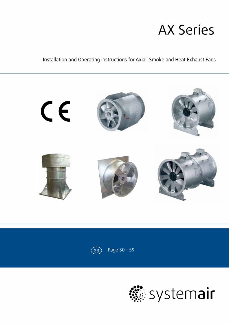
Installation and Operating Instructions for Axial, Smoke and Heat Exhaust Fans
AX Series
GB Page 30 - 59
The data stated in these operating instructions are merely for the purpose of describing the product. Information about a certain pro-perty or suitability for a certain purpose of use cannot be derived from our information. The information does not release the user from his own assessments and examin-ations.Please consider the fact that our products are subject to a natural wear and ageing process.All rights are with Systemair GmbH, also for the event of applications for protective rights.Any powers of use, such as copying and forwarding rights, are with us.An exemplary configuration has been shown on the title page. The product supplied can therefore deviate from the illustration. The original operating instructions have been written in the German lan-guage.
30
Axial, smoke and heat exhaust fans, series AX

Table of contents
1 Information on use of the documentation ..................... 32
2 Technical data ................................................................... 33
2.1 Type key ..................................................................................... 33
2.2 Name plate ................................................................................ 34
2.3 Types of fans ............................................................................. 35
2.4 Data of the fans ........................................................................ 35
2.5 Data of the motor ..................................................................... 35
2.6 Electrical connection ............................................................... 35
3 Proper use ........................................................................ 36
4 Personnel .......................................................................... 37
4.1 Qualification .............................................................................. 37
4.2 Personal protective equipment ............................................. 37
5 General safety information ............................................ 38
6 Safety devices .................................................................. 39
7 Constructional set-up ...................................................... 39
8 Mode of operation ........................................................... 41
9 Inspection ......................................................................... 41
10 Transport, storage, assembly ........................................ 41
10.1 Transport ................................................................................... 42
10.2 Storage ...................................................................................... 42
10.3 Assembly ................................................................................... 43
10.4 Electrical connection ...............................................................48
10.5 Adjusting the blade angle ...................................................... 50
11 Commissioning ................................................................. 50
12 Operation .......................................................................... 51
12.1 Speed-controlled fan operation ............................................ 51
13 Maintenance and upkeep ................................................ 53
14 Fault table, remedying faults .......................................... 54
15 Stoppage, disposal ........................................................... 55
16 Spare parts ....................................................................... 55
17 After-sales service .......................................................... 55
18 Commissioningcertificat ................................................. 56
19 Declaration of conformity ............................................... 57
31AX - 01.2013
Axial, smoke and heat exhaust fans, series AX
1 Information on use of the documentation
To find information quickly, the documentation has been provided with a table of contents at the beginning. The foot line contains the current version of the documentation and the page number.
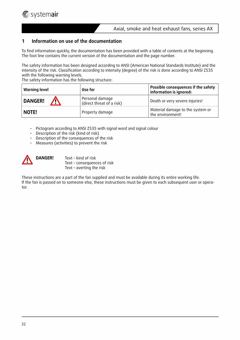
The safety information has been designed according to ANSI (American National Standards Institute) and the intensity of the risk. Classification according to intensity (degree) of the risk is done according to ANSI Z535 with the following warning levels.The safety information has the following structure:
• Pictogram according to ANSI Z535 with signal word and signal colour• Description of the risk (kind of risk)• Description of the consequences of the risk• Measures (activities) to prevent the risk
DANGER! Text – kind of riskText – consequences of riskText – averting the risk
These instructions are a part of the fan supplied and must be available during its entire working life. If the fan is passed on to someone else, these instructions must be given to each subsequent user or opera-tor.
Warning level Use for Possible consequences if the safety information is ignored:
DANGER! Personal damage (direct threat of a risk) Death or very severe injuries!
NOTE! Property damage Material damage to the system or the environment!
32
Axial, smoke and heat exhaust fans, series AX
2 Technical data
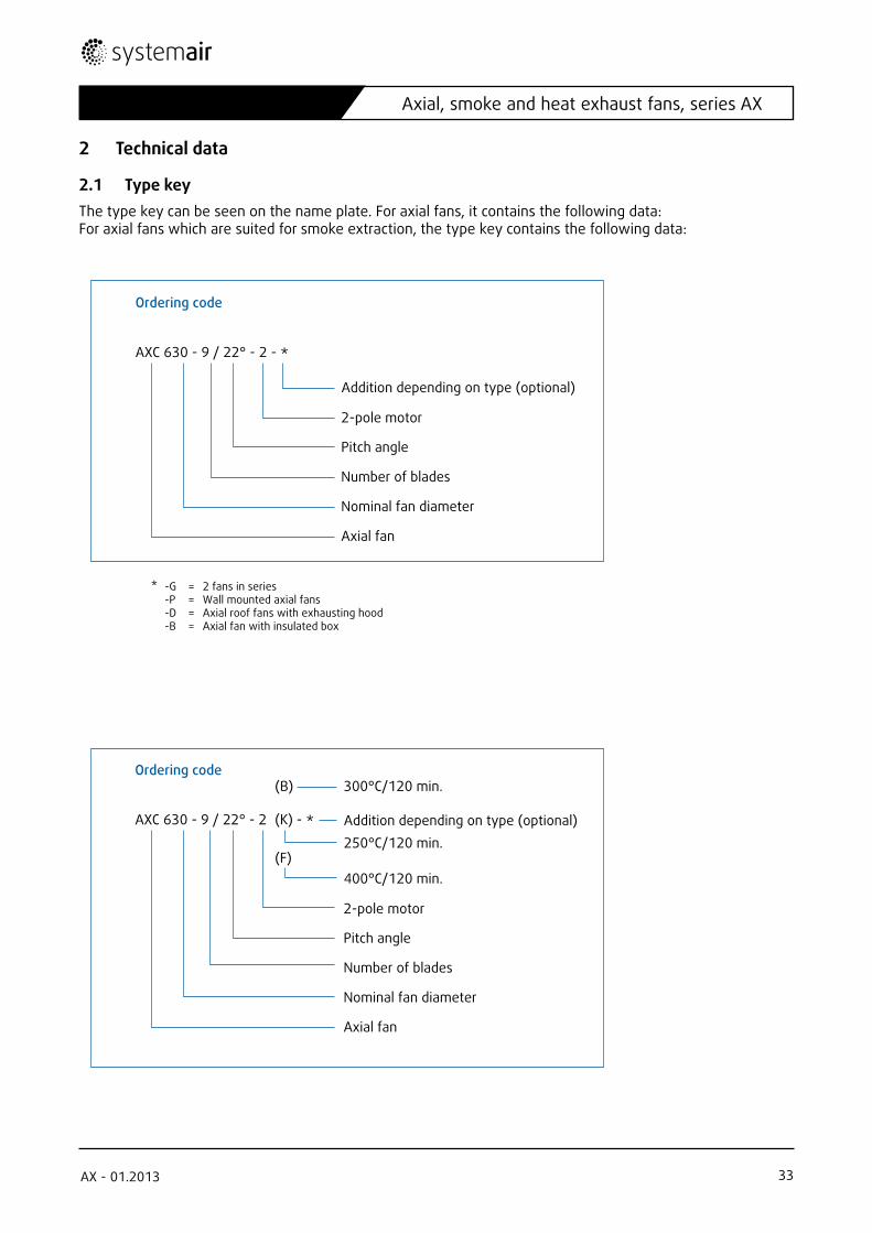
2.1 Type keyThe type key can be seen on the name plate. For axial fans, it contains the following data: For axial fans which are suited for smoke extraction, the type key contains the following data:
Ordering code
AXC 630 - 9 / 22° - 2 - *
2-pole motor
Pitch angle
Number of blades
Nominal fan diameter
Axial fan
(B) 300°C/120 min.
(F)
(K)
400°C/120 min.
250°C/120 min.Addition depending on type (optional)
Ordering code
AXC 630 - 9 / 22° - 2 - *
2-pole motor
Pitch angle
Number of blades
Nominal fan diameter
Axial fan
Addition depending on type (optional)
* -G = 2 fans in series-P = Wall mounted axial fans-D = Axial roof fans with exhausting hood-B = Axial fan with insulated box
33AX - 01.2013
Axial, smoke and heat exhaust fans, series AX
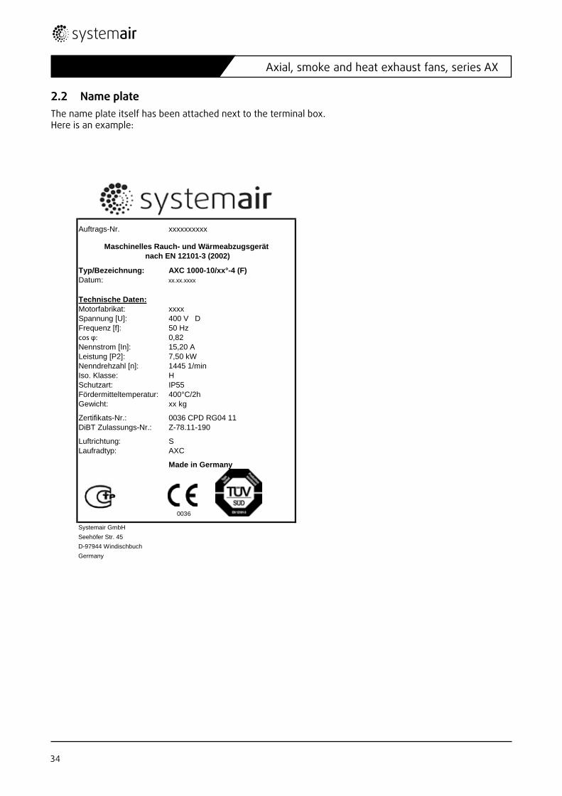
2.2 Name plateThe name plate itself has been attached next to the terminal box.Here is an example:
Auftrags-Nr. xxxxxxxxxx
Typ/Bezeichnung: AXC 1000-10/xx°-4 (F)Datum: xx.xx.xxxx
Technische Daten:Motorfabrikat: xxxxSpannung [U]: 400 V DFrequenz [f]: 50 Hzcos φ: 0,82Nennstrom [In]: 15,20 ALeistung [P2]: 7,50 kWNenndrehzahl [n]: 1445 1/minIso. Klasse: HSchutzart: IP55Fördermitteltemperatur: 400°C/2hGewicht: xx kg
Zertifikats-Nr.: 0036 CPD RG04 11DiBT Zulassungs-Nr.: Z-78.11-190
Luftrichtung: SLaufradtyp: AXC
Made in Germany
0036
Systemair GmbHSeehöfer Str. 45D-97944 WindischbuchGermany
Maschinelles Rauch- und Wärmeabzugsgerät nach EN 12101-3 (2002)
34
Axial, smoke and heat exhaust fans, series AX
2.3 Types of fans
AXC …......... Axial fan up to a max. long-term temperature of 55°CAXC…..…(B) Smoke exhaust axial fan, F300, EN12101-3 (300 °C/120 min)AXC……..(F) Smoke exhaust axial fan, F400, EN12101-3 (400 °C/120 min)AXC........(K) Smoke exhaust axial fan, F250, EN12101-3 (250 °C/120 min.)AXR …......... Fan with truly reversible impellerAXR……..(B) Reversible smoke exhaust axial fan, F300, EN12101-3 (300 °C/120 min) AXR……. (F) Reversible smoke exhaust axial fan, F400, EN12101-3 (400 °C/120 min)AXR........(K) Reversible smoke exhaust axial fan, F250, EN12101-3 (250 °C/120 min)AXCBF ……. Thermo fan with encapsulated motor, permanent operation temp. up to a max. of 200 °C
Possible combinations:AXC….-D Axial fan, roof mounting version with roof cowl and base frameAXC….-P Axial fan, wall mounting versionAXC….-B Axial fan, inside a sound-insulated boxAXC….-G Axial fan, 2 fans connected in series (2-stage)AXC….-G-B Axial fan, 2 fans connected in series (2-stage) inside a sound-isolated box
AXC…(B)-D Smoke exhaust axial fan, roof mounting version with roof cowl and base frameAXC…(B)-P Smoke exhaust axial fan, wall mounting versionAXC…(B)-B Smoke exhaust axial fan in sound-isolated boxAXC…(B)-G Smoke exhaust axial fan, 2 fans connected in series (2-stage)AXC..(B)-G-B Smoke exhaust axial fan, 2 fans connected in series (2-stage) inside a sound-isolated box
AXC…(F)-B Smoke exhaust axial fan in sound-isolated boxAXC…(F)-G Smoke exhaust axial fan, 2 fans connected in series (2-stage)AXC..(F)-G-B Smoke exhaust axial fan, 2 fans connected in series (2-stage) inside a sound-isolated box
2.4 Data of the fans
2.5 Data of the motorAll the necessary data can be obtained from the operating instructions from the manufacturer of the motor.
2.6 Electrical connectionAll the necessary data can be seen from the name plate in question or from the enclosed data sheet.Admis-sible voltage tolerances according to IEC38: maximum +6 % or –10 % The measured curren may only exceed the nominal current at nominal voltage by a maximum of 5 %. The wiring scheme and the manufacturer‘s declaration from the manufacturer of the motor have been enclosed with the documentation.
Weight See data sheetProtection class See data sheetVoltage/current intensity See data sheetSound pressure level See data sheetAdmissible ambient temperature See data sheetAdmissible temperature for conveying See data sheetNominal diameter See data sheet
35AX - 01.2013
Axial, smoke and heat exhaust fans, series AX
Motor protection
Type Motor protection
Thermal protection, standard Speed regulation
AXC, -B, -D, -G, -P by customer PTC possible via frequency inverter.
AXC (B), (F), (K)AXR (B), (F), (K) without without
(PTC optional)possible via frequency inverter, needs to be bridged in case of fire
AXR by customer PTC possible via frequency inverter
AXCBF by customer PTC possible via frequency inverter
3 Proper use
The axial fans of the series AXC/AXR/AXCBF in the versions B, D, G, P, (K), (B) are intended for installation in ventilation systems!
The axial fans of the series AXC/AXR/AXCBF in the versions B, D, G and P are ready-to-use products and are used as components for ventilation appliances, machines and systems. With these fans, air can be sucked out, inserted or also conveyed. As a standard, the fans are supplied with a thermal motor protection (PTC).
The fans can be installed both in channel systems and also with free suction via an admission nozzle and a suction-side contact protection grid. Free blow-out via a contact protection grid is also possible following prior consideration during design.
The axial fans may not be used in areas in which an explosion-capable atmosphere can be found. The fans are not suited for suction of dusty or aggressive media or media with such a content of dust that operation of the fan could be impaired by accumulation on the blades and on the fan housing.
• The maximum admissible operating data on the name plate apply to an air density ρ =1.2 kg/m³ (See level)and a maximum air humidity of 80 %. The fans are suited for an ambient temperature of no more than 55 °C (pay attention to information on name plate). The temperature of the material conveyed may not exceed 55 °C or fall below –20 °C.
• The maximum admissible temperatures stated above can be increased to an ambient temperature of 60 °C, 80 °C or even up to 100 °C (pay attention to precise information on name plate) by use of ISO H motors. The temperature of the material conveyed may then not exceed 100 °C or fall below –20 °C.
• With the use of specific motors (pay attention to precise information on name plate), the fans can also be used up to a maximum air humidity of 95 %.
• The motors cannot be voltage-controlled. Speed regulation is only possible via a customary frequency inverter, e.g. Systemair FRQ or FXDM.
36
Axial, smoke and heat exhaust fans, series AX

Type Differing uses
AXC-B Ventilator mounted in 20 mm isolated casing
AXC-D The „D“ series of axial fans is designed as a roof fan with a base plate and with roof cowl. Assembly on the roof.
AXC-P Fan has been provided with a fitting plate. Assembly on the wall
AXC-G
In the „G“ series, two fans are arranged behind one another. If one of the fans fails and the second fan continues to run, this specific arrangement ensures that at least 66 % of the total air volume flow originally planned can continue to be conveyed. This is necessary, amongst other things, in the use of the fans for removal of CO or also smoke extraction from garages.
AXC(B),AXC(K),AXR(B),AXR (K)
The smoke exhaust fans can also be used for CO removal. The temperature resistance of the smoke exhaust fans for the event of smoke removal can be seen from the name plate (300 °C/120 min). Version (B) is suited for exhaust of fire gases, temperature classification pursu-ant to DIN EN 12101 part 3 for at least one time 300 °C for 120 minutes. This series of fans can be also be used for daily ventilation as required, thus fulfilling a double function.These fans will be provided any without thermal protection.
AXC(F),AXR(F)
The smoke exhaust fans can also be used for CO removal. The temperature resistance of the smoke exhaust fans for the event of smoke removal can be seen from the name plate (400 °C/120 min). Version (F) is suited for exhaust of fire gases, temperature classification pursu-ant to DIN EN 12101 part 3 for at least one time 400 °C for 120 minutes. This series of fans can be also be used for daily ventilation as required, thus fulfilling a double function.These fans will be provided any without thermal protection.
AXR The direction of conveying can be reversed by switching over the direction of rotation.
AXCBF
The AXCBF series is suited as a standard for any temperature of no more than 200 °C.With speed control, the maximum admissible conveying temperature is 55 °C.The conveying temperature without regulation may not exceed 200 °C or fall below –20 °C.
Differing use of the types of fan
Any deviating use of the fans is deemed improper. No liability is assumed for any personal and/or property damage resulting from this.
4 Personnel
4.1 QualificationThe electrical connections of the fans may only be carried out by trained electricians.
4.2 Personal protective equipmentProtective working gloves, protective working shoes and goggles for assembly, installation, maintenance and control work are part of the personal protective equipment for assembly, maintenance and repair personnel.
37AX - 01.2013
Axial, smoke and heat exhaust fans, series AX
5 General safety information
• During assembly, commissioning, maintenance and controls, secure both the assembly area and also the premises for any preparations against access by unauthorised persons.
• A residual risk due to faulty conduct, malfunction or effects of force majeure in the operation of the fan cannot be completely ruled out. The planner, operator or builder of the appliance, machine or system must take suitable safety measures pursuant to DIN EN 12100 to prevent the occurrence of a risk situation.
• Please observe the general occupational safety directives.
• Ensure access to the fan for the purpose of upkeep and maintenance.
• Assembly and electrical installation may only be done by trained personnel complying with the relevant directives.
• The electrical connection may only be carried out by trained electricians. Before maintenance and repair work, switch the energy supply off.
• Rule out any risk by undesired switching on of the fan or undesired contact with the rotor during any work.
• The housing of the fan may not be deformed during assembly.
• Any risk by touching the rotor during operation must be ruled out.
• To avoid disturbances and to protect the motor, the latter must be disconnected from the mains by the integrated resistor in the event of a disturbance in operation (e.g. inadmissibly high media temperature) pursuant to Council Directive 94/9/EC.
• Maximum testing voltage of the resistors is 2.5 V.
• The motors contain triple resistors. More than two resistor chains may not be connected in series, as this can lead to an undefined cut-out.
• When checking the direction of rotation of the rotor, wear goggles.
• Safety elements, e.g. protective grids, may not be dismantled, circumvented or put out of function. They are to be checked for their secure positioning.
• Compliance with EMC Directive 89/336/EEC only relates to this product if it has been connected directly to the customary electricity mains. If this product is integrated into a system or completed and operated with other components (e.g. regulation and control appliances), the manufacturer or operator of the overall system is responsible for compliance with EMC Directive 89/336/EEC.
• The name plate states the electrical figures approved by the registration office in the EC type test (declara-tion of conformity) for the motor when optimally cooled.
• Prevent suction of foreign bodies, this can destroy the fan.
• Guarantee uninhibited and even flowing into the appliance and free blowing out again.
• The fans may not be used in explosive or hazardous areas.
38
Axial, smoke and heat exhaust fans, series AX
6 Safety devices
The motors have been provided with thermal protection via resistors (PTC) as a standard. Provision with thermocontacts is possible if required by the customer. The smoke exhaust versions (B) and (F) are provided without any thermal protection.
7 Constructional set-up
These fans are directly powered axial fans, in which the motor is positioned directly in the air flow. The main air direction is suctioned across the motor.
The outside of the fans is formed by a tubular housing of galvanized steel sheet, which has a flange with bores according to eurovent 1/2 standard pressed on both sides.
The axial impeller comprises an aluminium cast alloy and have profiled blades and an efficient hub ratio.
Directly powered axial fans are arranged with the motor inside the air flow. In B3 conventional motors, the motorbearing console is of galvanized steel sheet. In B30 pad mounted mo-tors, the motor is fitted on the housing via threaded rods or a welded motor support.
As a default, the fans are provided with three phase motors (400 V, 50 Hz) with integrated resistor. The elec-trical motor protection class is at least IP 54, ISO F.
The fans can be run in permanent operation from –20 °C to 55 °C ambient and conveying temperature.
The hub construction permits infinite adjustment of the blade angle at a standstill. The dynamic counterbalan-cing is done according to ISO 1940 T1, Class G 6.3.
The electrical connection is via a terminal box positioned on the outside of the housing, the motor connec-tions are carried out in the factory.
The standard motors of the axial fans are suited for operation with a frequency inverter. If the fans are controlled with a frequency inverter, connection of the thermal protection, resistor (standard PTC) or also thermocontacts (TC) in the motor is necessary.
39AX - 01.2013
Axial, smoke and heat exhaust fans, series AX

Type Constructional peculiarities
AXCAs a default, the fans are provided in protection class IP55, ISO F. The fan can be run in per-manent operation at 55 °C ambient and conveying temperature, in the ISO H version, it can be run at up to 100 °C, depending on the finish.
AXC-DFans are designed as roof fans. Assembly on the roof is via a base plate. In order to stop water entering, a blowing hood is arranged on the pressure side with a bird-protection grid. Snowload class 0.
AXC-P Fan has been provided with a base plate. Assembly is on a wall.
AXC-G Fans constructed as garage version. Arrangement of two fans in series, switched behind one another
AXR Impeller reversible. In reversing operation, approximated 100 % of the air output will be achieved. According to the installation location.
AXC(B),AXC(K),AXR(B),AXR(K)
Three phase motors (400 V, 50 Hz, type B3) without thermal protection, protection class: IP54, ISO H.The fan can be run both in permanent operation at 55 °C ambient temperature and also (once) for 120 min at 300 °C conveying temperature. Certified to EN12101-3 TU Munich, CE certificate, see annex. Temperature resistant terminal box. The connection wire from the motor to the terminal box is protected via an additional flexible metal hose. Standard motors without motor protection.
AXC(F),AXR(F)
Three phase motors (400 V, 50 Hz, type B30) without thermal protection, protection class: IP55, ISO H.The fan can be run both in permanent operation at 55 °C ambient temperature and also (once) for 120 min at 300 °C conveying temperature. Certified to EN12101-3, CE certificate, see annex. Temperature resistant terminal box. The connection wire from the motor to the terminal box is protected via an additional flexible metal hose. Standard motors without mo-tor protection.
AXCBF
Directly powered axial fan with motor outside the air flow. 400 V, 50 Hz in IP55 ISO F. Stan-dard conveying direction „D“, pressing across motor. The fan can be run in permanent operati-on up to 200 °C conveying temperature. Maximum ambient temperature until 55°C. Housing flanges on both sides with bores according to eurovent 1/2 standard.B3 conventional motors with add-on terminal box.
Constructional peculiarities of the types of fan
The axial fans have been developed as a standard for horizontal, standing assembly on vibration dampers. Suction across motor – air direction „S“. Following prior design, the fans can also be intended for vertical use – air direction „SO“ or „SU“ (see illustrations).
S SU SO
40
Axial, smoke and heat exhaust fans, series AX

8 Mode of operation
The fans can be run in permanent operation at a maximum ambient temperature of 55 °C and also a maxi-mum conveying temperature of 55 °C with ISO F motors.Standard Fans with ISO H motors can be run at up to 100 °C. For the operation of the motor, the embossed standard frequency is to be complied with.
9 Inspection
Before a fan is handed over to the customer, there is a trial run with the manufacturer as well as an operation test necessary.
10 Transport, storage, assembly
DANGER! Risk of injury if the fan falls down. Use suitable lifting equipment and fitting devices. Do not stand underneath the load! NOTE Risk of damage to the fan or parts of the fan. Do not transport the devices by the connection wire, the terminal box, the rotor, the protective grid or the admission nozzle. Use suitable lifting equipment and fitting devices! NOTE Risk of deformation of the fan! Load and unload the fan carefully. Pay attention to the transport arrows on the packaging.
Axial fan with accessories
airflow direction
1. SG Protection guard2. ESD-F Inlet cone3. RSA Silencer4. EV-AR/AXC, EVH (F400) flexible
connection5. REV (60°C) on/off switch6. REV (fire rated) on/off switch7. MP (4x angel 90°) Mounting brackets
from size 1120
8. MFA Mounting feet9. SD (4x) AV rubber mounts10. FSD (4x) AV spring mounts11. LRK Air operated damper12. GFL Counterflange13. ZSD (4x) Spring mounts for tensile load14. ABS Blowing out cowl15. MPR Mounting ring up to size 1000
Vertical assembly Horizontal assembly
1
3
5
7
2
4
6
8
911
1310
1214
15
3
4
10
11
5
7
41AX - 01.2013
Axial, smoke and heat exhaust fans, series AX
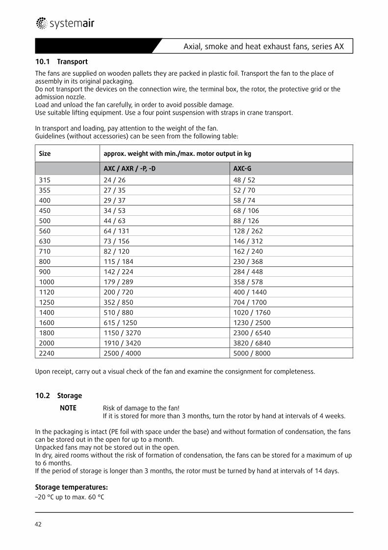
10.1 TransportThe fans are supplied on wooden pallets they are packed in plastic foil. Transport the fan to the place of assembly in its original packaging. Do not transport the devices on the connection wire, the terminal box, the rotor, the protective grid or the admission nozzle. Load and unload the fan carefully, in order to avoid possible damage. Use suitable lifting equipment. Use a four point suspension with straps in crane transport.
In transport and loading, pay attention to the weight of the fan. Guidelines (without accessories) can be seen from the following table:
Upon receipt, carry out a visual check of the fan and examine the consignment for completeness.
10.2 Storage
NOTE Risk of damage to the fan! If it is stored for more than 3 months, turn the rotor by hand at intervals of 4 weeks. In the packaging is intact (PE foil with space under the base) and without formation of condensation, the fans can be stored out in the open for up to a month. Unpacked fans may not be stored out in the open. In dry, aired rooms without the risk of formation of condensation, the fans can be stored for a maximum of up to 6 months. If the period of storage is longer than 3 months, the rotor must be turned by hand at intervals of 14 days.
Storage temperatures:–20 °C up to max. 60 °C
Size approx. weight with min./max. motor output in kg
AXC / AXR / -P, -D AXC-G
315 24 / 26 48 / 52355 27 / 35 52 / 70400 29 / 37 58 / 74450 34 / 53 68 / 106500 44 / 63 88 / 126560 64 / 131 128 / 262630 73 / 156 146 / 312710 82 / 120 162 / 240800 115 / 184 230 / 368900 142 / 224 284 / 4481000 179 / 289 358 / 5781120 200 / 720 400 / 14401250 352 / 850 704 / 17001400 510 / 880 1020 / 17601600 615 / 1250 1230 / 25001800 1150 / 3270 2300 / 65402000 1910 / 3420 3820 / 68402240 2500 / 4000 5000 / 8000
42
Axial, smoke and heat exhaust fans, series AX

10.3 AssemblyBefore delivery, each fan is examined in the factory.After removing the packaging and before the start of assembly, you must:• establish any possible transport damage,• examine manually whether the fan wheel runs freely,• examine the standard distance between the blade tip and the housing and• check that no condensation has formed.
DANGER! Move the rotor of the fan by hand before you install it in order to check whether it moves freely. Please pay attention that the fixing screws of the fan blades can stick out of the casing. Attention should be paid on this especially!
Before installation, check the minimum air gap between the blade tip and the housing according to the following table:
sizeAXC / AXRtip gap in mm
AXC, AXR (K) + (B)tip gap in mm
AXC, AXR (F)tip gap in mm size
AXCBFtip gap in mm
min. max. min. max. min. max. min. max.315, 355, 400 1 3 2 3,5 4 6 250 2 3,5450 2 4 3 4,5 4,5 6,5 315 2 3,5500 2 4 3 4,5 5 7 400 2 3,5560 2 5 4 5,5 6 8 500 3 4,5630 2 5 4 5,5 7 9 630 4 5,5710 2 5 4 5,5 7 9 800 5 6,5800 2 6 5 6,5 8 10900 2 6 5 6,5 9 111000 3 6,5 5 7 10 121120 3 8 6,5 8,5 11,5 141250 3 8,5 7 9 12,5 151400 6 9 7,5 9,5 14 161600 7 10 8 11,5 16 181800 10 14 11,5 15,5 - -2000 10 14 11,5 15,5 - -2240 11,5 15,5 13 18 - -
If the figures established do not match the nominal dimensions, do not fit the fan. Notify the manufacturer for the purpose of correction of the air gap.
DANGER! Risk of injuries if the safety directives are not observed. In assembly, please observe the general occupational safety directives! DANGER! Risk of injury if the fan falls down! During assembly, secure both the assembly area and also the premises for any prepa- rations against access by unauthorised persons. DANGER! Risk of injuries from electric shocks! Switch the energy supply off before you make the electric connection of the fan. Make sure that the energy supply cannot be switched on again prematurely. The electrical installation may only be done by trained personnel. DANGER! Risk of injuries from rotating parts! Rule out any risk by undesired switching on of the fan or undesired contact with the rotor during assembly.
43AX - 01.2013
Axial, smoke and heat exhaust fans, series AX
NOTE Risk of damage to the fan! The fan housing may not be deformed during assembly. Carry out the assembly carefully!
NOTE Risk of damage to the fan! Check by hand whether the rotor can be moved freely! Do not fit the fan if the rotor cannot be moved freely. Notify the manufacturer.
NOTE Risk of damage to the fan! Prevent foreign bodies from being sucked in. NOTE Risk of damage to the fan! If the flow gets jammed, there is the risk of overheating. Guarantee uninhibited and even flowing into the appliance and free blowing out.
• If the gap dimensions are correct, fit the fan in such a way that the impeller cannot be touched during operation.
• Provide the fan at least with an IP 20 protective grid with free intake and free blow-out.
• Prevent the possibility of foreign bodies being taken in!
• Guarantee uninhibited and even flowing into the appliance and free blowing out!
• Fit the fan in such a way that access to the fan for the purpose of maintenance work is always guaranteed and the fan can be dismantled without disproportionate efforts being necessary.
• Ensure sufficient free space in the vicinity of the fan in order to be able to carry out any necessary maintenance work.
• Fit the fan in the correct direction of air flow (in accordance with the arrow on the device).
• Fit the fan with B3 motors and with „air direction S“ in such a way that the mounting feets of the electric motor are horizontal below the motor.
To avoid vibration transmissions to the channel system, installation of compensators with the corresponding registrations (if necessary) is recommended.
In order to avoid vibration transmissions to surrounding components, installation of vibration dampers and canvas supports is recommended.
NOTE Risk of damage to the fan. Spring vibration mounts of unsuited materials do not fulfil their function! For smoke exhaust fans (B), (K) and (F) only use spring vibration mounts made of steel, e.g. Systemair FSD or ZSD.
44
Axial, smoke and heat exhaust fans, series AX
Special points in the assembly of the types of fan:
Notes on the installation of the air channels
NOTE Risk of damage to the fan. If the dampers are fitted incorrectly, they will not function. Install the air-acting dampers vertically. If you install the air-acting damper horizontally then only with the damper opening pointing upwards. NOTE Risk of damage to the fan. If the flap traps are fitted incorrectly in smoke exhaust fans, no warranty will be assumed by Systemair! Only install the flap traps in smoke exhaust fans in the air direction behind the fan (pressure side). This is the only way to comply with the tested arrangement. NOTE Risk of damage to the fan and the complete system! If unsuited fittings are used, the smoke exhaust fans can become loose. Only use fittings with fire resistance classes which match the case of use in question! NOTE Risk of damage to the fan and the complete system! If unsuited materials are used for channel systems of smoke exhaust fans, damage can occur on the fans or on the overall system. Only use fittings with fire resistance classes which match the case of use in question! NOTE Risk of damage to the fan and the complete system! If there is not sufficient access to the fitted fan, maintenance work cannot be done to the necessary extent. In the case of damage, remedying the cause may be hampered. In both cases, subsequent damage to the fan and to the overall system is possible! Fit the fans in such a way that there is sufficient access for maintenance and upkeep purposes!
Type Special points in the assembly:
AXC-D
In the „D“ series, the axial roof fan is to be fitted on a correspondingly stable base. You will see the weight of the fan in the corresponding table. In order to avoid formation of condensation, the base is to be insulated from the inside. The base is to be integrated into the roof tightly by the customer, e.g. by adhesion with welded tracks of bitumen on the base.
AXC-P
The „P“ series of axial fans is to be fitted to a wall construction. The wall construction and the fitting of the fan must be adapted to the weight of the fan. You will see the weight of the fan in the table under Point 10.1 Transport.
AXC (B), (K), (F)AXR (B), (K), (F)
Smoke exhaust fans are suited for positioning inside a building in the fire room, inside the building in a separate room and out in the open. If they are positioned outside the fire zone, but still inside the building, the fan must be provided with heat insulation by the customer. The heat insulation must be provided with fireproof material L120 according to DIN 4102-4.
45AX - 01.2013
Axial, smoke and heat exhaust fans, series AX
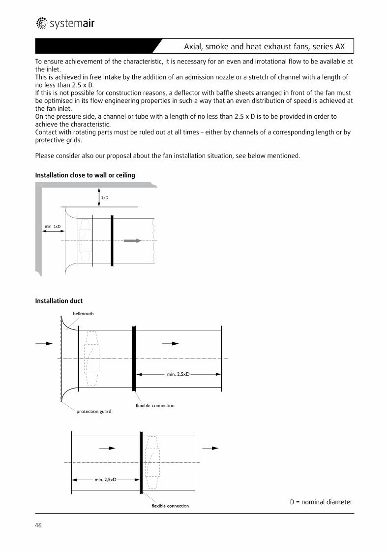
To ensure achievement of the characteristic, it is necessary for an even and irrotational flow to be available at the inlet.This is achieved in free intake by the addition of an admission nozzle or a stretch of channel with a length of no less than 2.5 x D. If this is not possible for construction reasons, a deflector with baffle sheets arranged in front of the fan must be optimised in its flow engineering properties in such a way that an even distribution of speed is achieved at the fan inlet. On the pressure side, a channel or tube with a length of no less than 2.5 x D is to be provided in order to achieve the characteristic. Contact with rotating parts must be ruled out at all times – either by channels of a corresponding length or by protective grids.
Please consider also our proposal about the fan installation situation, see below mentioned.
Installation close to wall or ceiling
Installation duct
min. 1xD
1xD
flexible connection
min. 2,5xD
flexible connection
bellmouth
protection guard
min. 2,5xD
D = nominal diameter
46
Axial, smoke and heat exhaust fans, series AX
bellmouth
flexible connectionwith back-up ring
flexible connection
bellmouth
flexible connectionwith back-up ring
flexible connection
Installation Silencer
The fans have suitable sealing measures. However, the manufacturer assumes no warranty for connections by the customer. When the fans are fitted, the operator of the system must carry out a leakage test of the system (before commissioning!) in accordance with legal requirements.
The complete channel system via which smoke and fire gases are exhausted must fulfil the required fire resis-tance classes according to local regulations.
When fitting the flexible connections, make sure that they are fitted according to the stretched length (see following table), without congestion or tensile strain. They are not used to compensate any lack of precision in the assembly.
Install the flexible connections offset, so that there is no reduction in efficiency or a development of noise.
flow cage
perforated sheet
diffusor with inner core
flow cage
perforated sheet
diffusor with inner core
47AX - 01.2013
Axial, smoke and heat exhaust fans, series AX
10.4 Electrical connection
DANGER! Risk of injuries from electric current! Switch the energy supply off before you bring about the electrical connection of the fan. Make sure that the energy supply cannot be switched on again prematurely. The electrical connection may only be carried out by trained electricians. DANGER! Risk of injuries from electric voltage! Check whether the electrical data on the name plate match up with the local mains connection, e.g. of the switch cabinet.
The electrical connection is to be done according to valid directives and only by a qualified fitter with matching safety devices for the protection of the motor (start and overload).
The nominal data on the name plate of the device must match up with the mains voltage and frequency.
Voltage tolerances are admissible with a maximum of +6 % or –10 % according to IEC38. The measured current may only exceed the nominal current at nominal voltage by a maximum of 5 %.
Fans provided with resistors (PTC) must always be connected to an external motor protection. The motors cannot be voltage controlled. Speed regulation is only possible via a customary frequency inverter. The wiring scheme and the manufacturer‘s declaration from the manufacturer of the motor have been enc-losed with the documentation.
• Carry out the electrical connection directly on the connection box according to the wiring scheme in the lid of the connection box and comply with local directives.
Special points in the assembly of the types of fan:
• Please find the electrical data on the name plate or the enclosed data sheet.
It is recommended that all motors are to be provided with a protective motor switch (not included in the scope of delivery). Nothing may be fitted to the fan housing.
Typ Electrical connection
AXC, - B, -D, -G The connection is via the terminal box fitted on the outside of the housing.
AXC-P The motor connection wire must be connected to the provided terminal box. The terminal box is to be positioned to match the assembly situation of the fan.
AXR The connection is via the terminal box fitted on the outside of the housing.
AXC (B), (K), (F)AXR (B), (K), (F) The connection is via the terminal box fitted on the outside of the housing.
AXCBF The connection is via the terminal box added on the motor.
48
Axial, smoke and heat exhaust fans, series AX
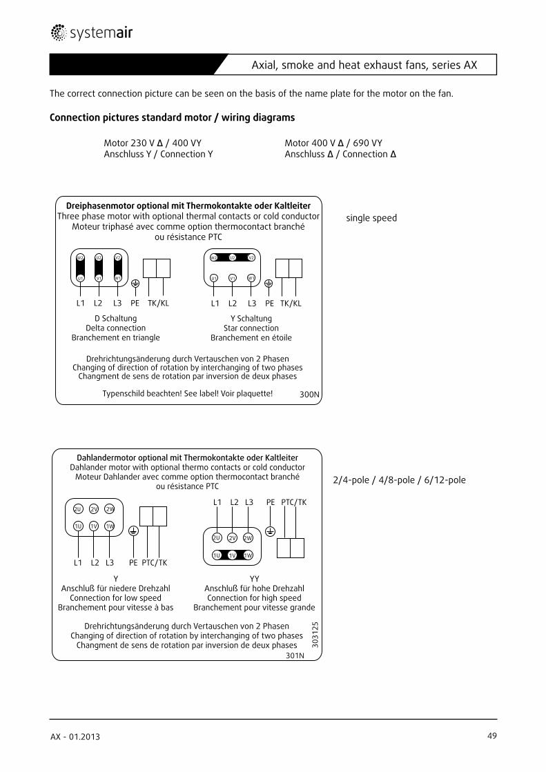
The correct connection picture can be seen on the basis of the name plate for the motor on the fan.
Connection pictures standard motor / wiring diagrams
Motor 230 V ∆ / 400 VY Motor 400 V ∆ / 690 VY Anschluss Y / Connection Y Anschluss ∆ / Connection ∆
single speed
2/4-pole / 4/8-pole / 6/12-pole
70 x 55 mm
Dreiphasenmotor optional mit Thermokontakte oder KaltleiterThree phase motor with optional thermal contacts or cold conductor
Moteur triphasé avec comme option thermocontact branchéou résistance PTC
D SchaltungDelta connection
Branchement en triangle
Y SchaltungStar connection
Branchement en étoile
Drehrichtungsänderung durch Vertauschen von 2 PhasenChanging of direction of rotation by interchanging of two phases
Changment de sens de rotation par inversion de deux phases
Typenschild beachten! See label! Voir plaquette! 300N
L1 L2 L3 PE TK/KL L1 L2 L3 PE TK/KL
W2 U2 V2
U1 V1 W1
W2 U2 V2
U1 V1 W1
70 x 55 mm
Dahlandermotor optional mit Thermokontakte oder KaltleiterDahlander motor with optional thermo contacts or cold conductor
Moteur Dahlander avec comme option thermocontact branchéou résistance PTC
YAnschluß für niedere Drehzahl
Connection for low speedBranchement pour vitesse à bas
Drehrichtungsänderung durch Vertauschen von 2 PhasenChanging of direction of rotation by interchanging of two phases
Changment de sens de rotation par inversion de deux phases
YYAnschluß für hohe DrehzahlConnection for high speed
Branchement pour vitesse grande
L1 L2 L3 PE PTC/TK
L1 L2 L3 PE PTC/TK2V 2W2U
1U 1V 1W
2V 2W2U
1U 1V 1W
3031
25
301N
49AX - 01.2013
Axial, smoke and heat exhaust fans, series AX
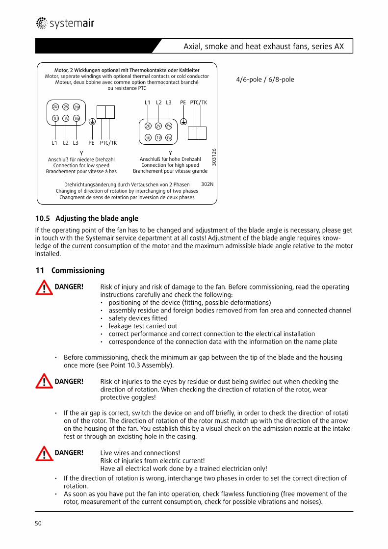
70 x 55mm
Motor, 2 Wicklungen optional mit Thermokontakte oder KaltleiterMotor, seperate windings with optional thermal contacts or cold conductor
Moteur, deux bobine avec comme option thermocontact branchéou resistance PTC
YAnschluß für niedere Drehzahl
Connection for low speedBranchement pour vitesse á bas
Drehrichtungsänderung durch Vertauschen von 2 PhasenChanging of direction of rotation by interchanging of two phases
Changment de sens de rotation par inversion de deux phases
302N
L1 L2 L3 PE PTC/TK
L1 L2 L3 PE PTC/TK2U 2V 2W
1U 1V 1W
2U 2V 2W
1U 1V 1W
YAnschluß für hohe DrehzahlConnection for high speed
Branchement pour vitesse grande
3031
26
4/6-pole / 6/8-pole
10.5 Adjusting the blade angleIf the operating point of the fan has to be changed and adjustment of the blade angle is necessary, please get in touch with the Systemair service department at all costs! Adjustment of the blade angle requires know-ledge of the current consumption of the motor and the maximum admissible blade angle relative to the motor installed.
11 Commissioning
DANGER! Risk of injury and risk of damage to the fan. Before commissioning, read the operating instructions carefully and check the following: • positioning of the device (fitting, possible deformations) • assembly residue and foreign bodies removed from fan area and connected channel • safety devices fitted • leakage test carried out • correct performance and correct connection to the electrical installation • correspondence of the connection data with the information on the name plate • Before commissioning, check the minimum air gap between the tip of the blade and the housing once more (see Point 10.3 Assembly).
DANGER! Risk of injuries to the eyes by residue or dust being swirled out when checking the direction of rotation. When checking the direction of rotation of the rotor, wear protective goggles! • If the air gap is correct, switch the device on and off briefly, in order to check the direction of rotati on of the rotor. The direction of rotation of the rotor must match up with the direction of the arrow on the housing of the fan. You establish this by a visual check on the admission nozzle at the intake fest or through an excisting hole in the casing.
DANGER! Live wires and connections! Risk of injuries from electric current! Have all electrical work done by a trained electrician only! • If the direction of rotation is wrong, interchange two phases in order to set the correct direction of rotation. • As soon as you have put the fan into operation, check flawless functioning (free movement of the rotor, measurement of the current consumption, check for possible vibrations and noises).
50
Axial, smoke and heat exhaust fans, series AX
NOTE Risk of damage to the fan! If the fan is operated outside the characteristic stated, there is the risk of unstable running and inadmissible vibrations, even possibly its destruction. Do not operate the fan outside the characteristic stated.
• Do not operate the fan outside the characteristic stated. This can happen in the case of a bad flow or excessively high resistance in the system. The fan must run on its prescribed operating point.
• Fill in the attached commissioning record sheet and present it in the event of a warranty claim.
12 Operation
When operating the fan, pay attention to the operating instructions from the motor manufacturer.Regularly check the flawless functioning of the fan (free movement of the rotor, measurement of the current consumption, check for possible vibrations and noises).
12.1 Speed-controlled fan operation
General: Fans can be speed-controlled to reach the required operation point of the installation and user requirements.
Speed-control, maximum speed:The speed specified on the name plate must not be exceeded.
Counter-measures in case of resonance frequencies:Excitation of mechanical components causes resonance frequencies. Improper high oscillations and malfunc-tions could be the result. This may damage impellers, shafts, bearings, housing parts or external components.
Excitation frequencies are caused by e.g. impeller, blade or motor rotations, blade rotational frequencies or aerodynamically. If the excitation frequency nears or meets the resonance frequency of a component, reso-nance oscillation may result in malfunctions. The exciter forces are affected by true running characteristics, balancing situation, aerodynamic forces and damping characteristics of the components.
WARNING! Risks due to resonance frequencies!Avoid continuous fan operation at speeds with increased oscillation values. These speeds must be skipped or deactivated during operation. Make sure that these stages will be passed quickly during start-up to avo-id transient oscillation and exceeding of the admissing oscillation of the resonance frequency. A permanent oscillation monitoring is recommended to ensure a safe and continuous fan operation.
Take a close look on oscillation damages during fan inspection and maintenance. It is recommended to change or increase the maintenance cycle to apply the operating conditions during normal operation speed. In these cases, it is usual to start with short maintenance rates after commissioning. If no damages occur, the rates can be changed stepwise to meet the specified maintenance rates from the operating instructions. This decision has to be made by the installation owner.
Commissioning of speed-controlled fansIt is necessary to check out the fan for oscillations at all normal operation speeds during commissioning. Oscillations on housing and bearing areas have to be determined and evaluated in accordance with DIN ISO 14694 depending on motor power and positioning. The admissible oscillation velocities can be requested from Systemair.
Measurable oscillation velocities depend e.g. on following factors: • positioning• bottom section/foundation state• flow conditions
51AX - 01.2013
Axial, smoke and heat exhaust fans, series AX
The operation point of the fan as well as used external devices and accessories also influence the running characteristics. Thus, an evaluation is only possible when the machine is installed for the proper operation. This evaluation must be done by trained personnel!
Speed-control, special regulations• Changing of the speed causes additional loads on the fan components. • Speed changing during normal regulation must not exceed the admissible motor temperature and the
bearing load. • Spin-up time should be at least 60 seconds. • The service life of fans can be extended by quick passing of the resonance frequencies. • Speed changings should be at max. 16,7 U/sec (1,75 rad/sec) (exception: passing of the resonance fre-
quencies). • The operating instructions of the control device manufacturer must be observed. • Comply with EMC Directive 2004/108/EG (1st March 2005).
General information:• The fan and the frequency inverter should be installed as near as possible to one another. • Use shielded and coated cables. • All components (fan, frequency inverter and motor) should be earthed. • The use of all-pole sinusoidal filters is recommended.• For control with frequency converter a falling below 10 Hz is inadvisable. Exceptions must be agreed
directly with the manufacturing plant.
52
Axial, smoke and heat exhaust fans, series AX
13 Maintenance and upkeep
DANGER! Live wires and connections! Risk of injuries from electric current! Have all electrical work done by a trained electrician only! Periodically check the following according to official requirements, however at least once a year (the fist four points only with the fan switched off!):
• screw connections, specifically the rotor fitting • is there dirt in the fan wheel? If so, remove it. • have accumulations formed on the rotor? If so, remove them. • function of the safety components • function of the control elements • coil resistance • operating current • vibrations which may occur • noises which may occur in the bearings of the electric motor • Motors with extended nipples needs to be re-greased (grease type please take from motor name tag or IMO from the motor manufacture) according to manufacturers‘ instructions.
Check the function of the system and controls (all poles) according to the system maintenance book at least every 3 months, if not required more often.Make the checks of the first four points with the fan switched off. The parameters of the other points may not deviate from the initial figures measured in installation. If one of the parameters deviates from the initial figures, replace the motor or the fan wheel or have them repaired by the manufacturer.In the event of unauthorised interventions, warranty becomes ineffective.Maintain the electric motor according to the enclosed instructions from the manufacturer.Use the enclosed maintenance record.
NOTE Risk of damage to the fan by cleaning with high pressure devices. Only clean the fan manually, with a vacuum cleaner or with compressed air!
NOTE Risk of damage to the fan! Systemair assumes no liability for damage caused by using outside parts. Only use original Systemair spare parts.
53AX - 01.2013
Axial, smoke and heat exhaust fans, series AX
14 Fault table, remedying faults
DANGER! Live wires and connections! Risk of injuries from electric current! Have all electrical work done by a trained electrician only!
DANGER! Risk of injuries to the eyes by residue or dust being swirled out when checking the direction of rotation. When checking the direction of rotation of the rotor, wear protective goggles!
If in doubt, get in touch with the manufacturer‘s after-sales service.
Fault Remedy
Fan does not start Check energy supply and motor protection. If in order, check motor. In motors with separated coils, check both speeds.
Volume flow too lowCheck direction of rotation. If necessary, change direction of rotation of motor by interchanging two phases. Check whether the intake area is blocked. Check working point and version of the system.
Motor protection is triggeredCompare the motor data. If in order, check energy supply and motor (short circuit, bearing damage, rotor blocked or grinding), contact after-sales service.
Abnormal noises occur
As a matter of principle: noise development in a fan greatly depends on the installation situation and the operating conditions. For this reason, no generally valid noise data can be given, they always relate to the measu-red conditions. They can be seen from our data sheets.Possible source of fault:• bearing damage on the motor, rotor blocked or grinding• rotor imbalanced or damaged• rotor with differing blade settings• rotor runs in the breakdown area• loose components.Have the motor or possibly the entire fan repaired.
Vibrations
Check working point and version of the system. If the actual total resis-tance of the system is higher than planned, this may result in the fan working in the breakdown area for some types.Contact the manufacturer‘s after-sales service.Damage or dust accumulations on the rotor.Check welding seams on the housing.
54
Axial, smoke and heat exhaust fans, series AX
15 Stoppage, disposal
DANGER! Live wires and connections!Risk of injuries from electric current!Have all electrical work done by a trained electrician only!
DANGER! Risk of injury if the fan falls down.During dismantling, secure the assembly area against unauthorised access!Use suitable lifting equipment and fitting devices. Do not stand underneath the load.
• To take the fan out of operation, disconnect the electrical connections from the mains.• Take the motor out of operation according to the operating instructions from the manufacturer and
dispose of it as stated there.• After the fan has finally been stopped, dispose of all the materials according to valid directives and
laws!
16 Spare parts
Defective fans must be completely replaced. Repairs may only be done on the manufacturer‘s premises and by the manufacturer.
17 After-sales service
Our after-sales service is at your disposal under the following contact data:
Systemair GmbHSeehöfer Str. 45D-97944 Windischbuch
Technical Support: Tel.: +49 (0)7930/9272-730Fax: +49 (0)7930/9273-736
55AX - 01.2013
Axial, smoke and heat exhaust fans, series AX
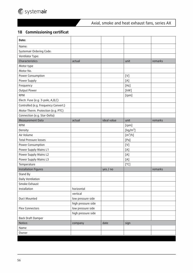
18 Commissioningcertificat
Date:
Name:
Systemair Ordering Code:
Ventilator Type:
Characteristics actual unit remarks
Motor type
Motor No.
Power Consumption [V]
Power Supply [A]
Frequency [Hz]
Output Power [kW]
RPM [rpm]
Electr. Fuse (e.g. 3-pole, A,B,C)
Controlled (e.g. Frequency Convert.)
Motor Therm. Protection (e.g. PTC)
Connection (e.g. Star-Delta)
Measurement Data actual ideal value unit remarks
RPM [rpm]
Density [kg/m³]
Air Volume [m³/h]
Total Pressure losses [Pa]
Power Consumption [V]
Power Supply Mains L1 [A]
Power Supply Mains L2 [A]
Power Supply Mains L3 [A]
Temperature [°C]
Installation Figures yes / no remarks
Stand By
Daily Ventilation
Smoke Exhaust
Installation horizontal
vertical
Duct Mounted low pressure side
high pressure side
Flex Connectors low pressure side
high pressure side
Back Draft Damper
Notice: company date sign
Name
Owner
The electrical connections of the fans may only be carried out by trained electricians.
56
Axial, smoke and heat exhaust fans, series AX
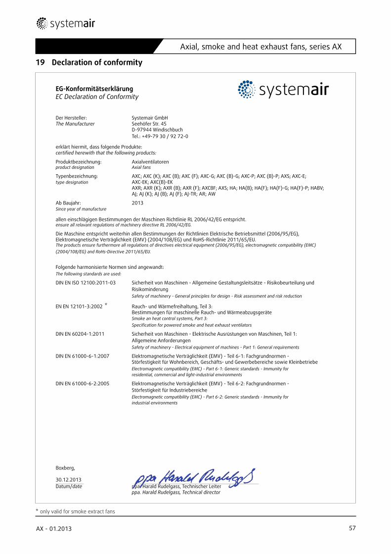
19 Declaration of conformity
EG-KonformitätserklärungEC Declaration of Conformity
Der Hersteller: Systemair GmbHThe Manufacturer Seehöfer Str. 45 D-97944 Windischbuch Tel.: +49-79 30 / 92 72-0
erklärt hiermit, dass folgende Produkte:certified herewith that the following products:
Produktbezeichnung: Axialventilatorenproduct designation Axial fans
Typenbezeichnung: AXC; AXC (K); AXC (B); AXC (F); AXC-G; AXC (B)-G; AXC-P; AXC (B)-P; AXS; AXC-E; type designation AXC-EK; AXC(B)-EK AXR; AXR (K); AXR (B); AXR (F); AXCBF; AXS; HA; HA(B); HA(F); HA(F)-G; HA(F)-P; HABV; AJ; AJ (K); AJ (B); AJ (F); AJ-TR; AR; AW
Ab Baujahr: 2013Since year of manufacture
allen einschlägigen Bestimmungen der Maschinen Richtlinie RL 2006/42/EG entspricht.ensure all relavant regulations of machinery directive RL 2006/42/EG.
Die Maschine entspricht weiterhin allen Bestimmungen der Richtlinien Elektrische Betriebsmittel (2006/95/EG), Elektromagnetische Verträglichkeit (EMV) (2004/108/EG) und RoHS-Richtlinie 2011/65/EU. The products ensure furthermore all regulations of directives electrical equipment (2006/95/EG), electromagnetic compatibility (EMC) (2004/108/EG) and RoHs-Directive 2011/65/EU.
Folgende harmonisierte Normen sind angewandt:The following standards are used:
DIN EN ISO 12100:2011-03 Sicherheit von Maschinen - Allgemeine Gestaltungsleitsätze - Risikobeurteilung und Risikominderung Safety of machinery - General principles for design - Risk assessment and risk reduction
EN EN 12101-3:2002 Rauch- und Wärmefreihaltung, Teil 3: Bestimmungen für maschinelle Rauch- und Wärmeabzugsgeräte Smoke an heat control systems, Part 3: Specification for powered smoke and heat exhaust ventilators
DIN EN 60204-1:2011 Sicherheit von Maschinen - Elektrische Ausrüstungen von Maschinen, Teil 1: Allgemeine Anforderungen Safety of machinery - Electrical equipment of machines - Part 1: General requirements
DIN EN 61000-6-1:2007 Elektromagnetische Verträglichkeit (EMV) - Teil 6-1: Fachgrundnormen - Störfestigkeit für Wohnbereich, Geschäfts- und Gewerbebereiche sowie Kleinbetriebe Electromagnetic compatibility (EMC) - Part 6-1: Generic standards - Immunity for residential, commercial and light-industrial environments
DIN EN 61000-6-2:2005 Elektromagnetische Verträglichkeit (EMV) - Teil 6-2: Fachgrundnormen - Störfestigkeit für Industriebereiche Electromagnetic compatibility (EMC) - Part 6-2: Generic standards - Immunity for industrial environments
Boxberg,
30.12.2013 Datum/date ppa. Harald Rudelgass, Technischer Leiter ppa. Harald Rudelgass, Technical director
* only valid for smoke extract fans
*
57AX - 01.2013
Axial, smoke and heat exhaust fans, series AX

58
Axial, smoke and heat exhaust fans, series AX
59AX - 01.2013
Axial, smoke and heat exhaust fans, series AX
3080
13 •
Janu
ar 2
014