
Air Handling Unit...Systemair- we make in India Systemair started operations in India in 2006 to...
49
Air Handling Units Air Handling Unit SBA / BA
Transcript of Air Handling Unit...Systemair- we make in India Systemair started operations in India in 2006 to...

Air Handling Units
Air Handling Unit SBA / BA

Systemair around the globe
Systemair was founded in
1974 with an innovative
idea of creating an
in-line centrifugal fan
for circular ducts, which
simplified ventilation.
Today, our company is one
of the global leaders in the
field of ventilation & air
conditioning technology,
with its operations spread
across four continents. Our
main focus is to develop
products that supply,
extract, convey, heat, cool
and distribute air energy
efficiently in a building.
Our products are energy
efficient, robust, easy to
select, install and use.
50Countries with Sales Subsidiaries

ContentsSystemair worldwide......................................2-3
Systemair India................................................4-5
Air handling units - overview........................6-7
Example of applications ................................8-9
Components of Air handling units..............10-22
Control panel...................................................23
Selection tools................................................24-29
Unit dimensions.............................................30-39
Certifications...................................................40-43
Few of our valued customers......................44-47
27Production Facilities
Always close to you!
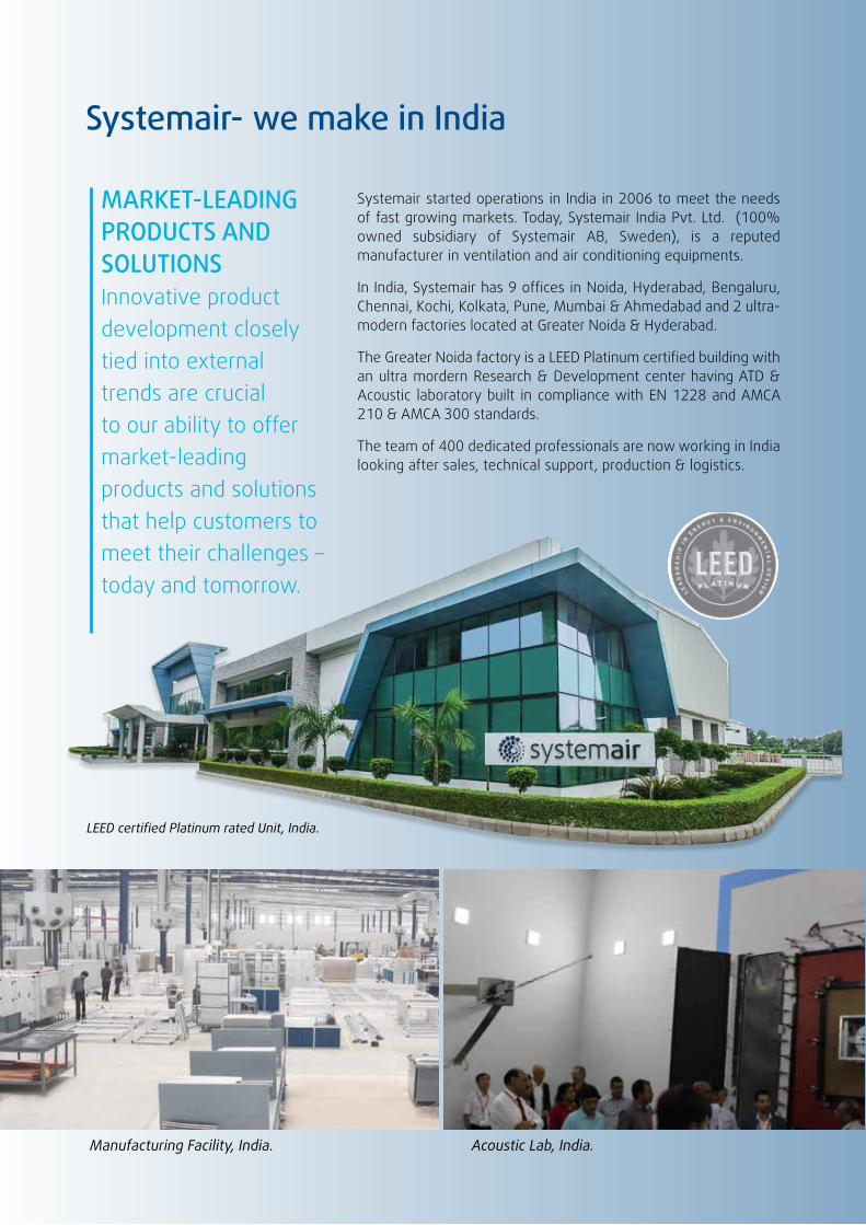
Systemair- we make in India
Systemair started operations in India in 2006 to meet the needs of fast growing markets. Today, Systemair India Pvt. Ltd. (100% owned subsidiary of Systemair AB, Sweden), is a reputed manufacturer in ventilation and air conditioning equipments.
In India, Systemair has 9 offices in Noida, Hyderabad, Bengaluru, Chennai, Kochi, Kolkata, Pune, Mumbai & Ahmedabad and 2 ultra-modern factories located at Greater Noida & Hyderabad.
The Greater Noida factory is a LEED Platinum certified building with an ultra mordern Research & Development center having ATD & Acoustic laboratory built in compliance with EN 1228 and AMCA 210 & AMCA 300 standards.
The team of 400 dedicated professionals are now working in India looking after sales, technical support, production & logistics.
MARKET-LEADING PRODUCTS AND SOLUTIONSInnovative product development closely tied into external trends are crucial to our ability to offermarket-leadingproducts and solutions that help customers to meet their challenges – today and tomorrow.
LEED certified Platinum rated Unit, India.
Acoustic Lab, India.Manufacturing Facility, India.
Systemair India | 5
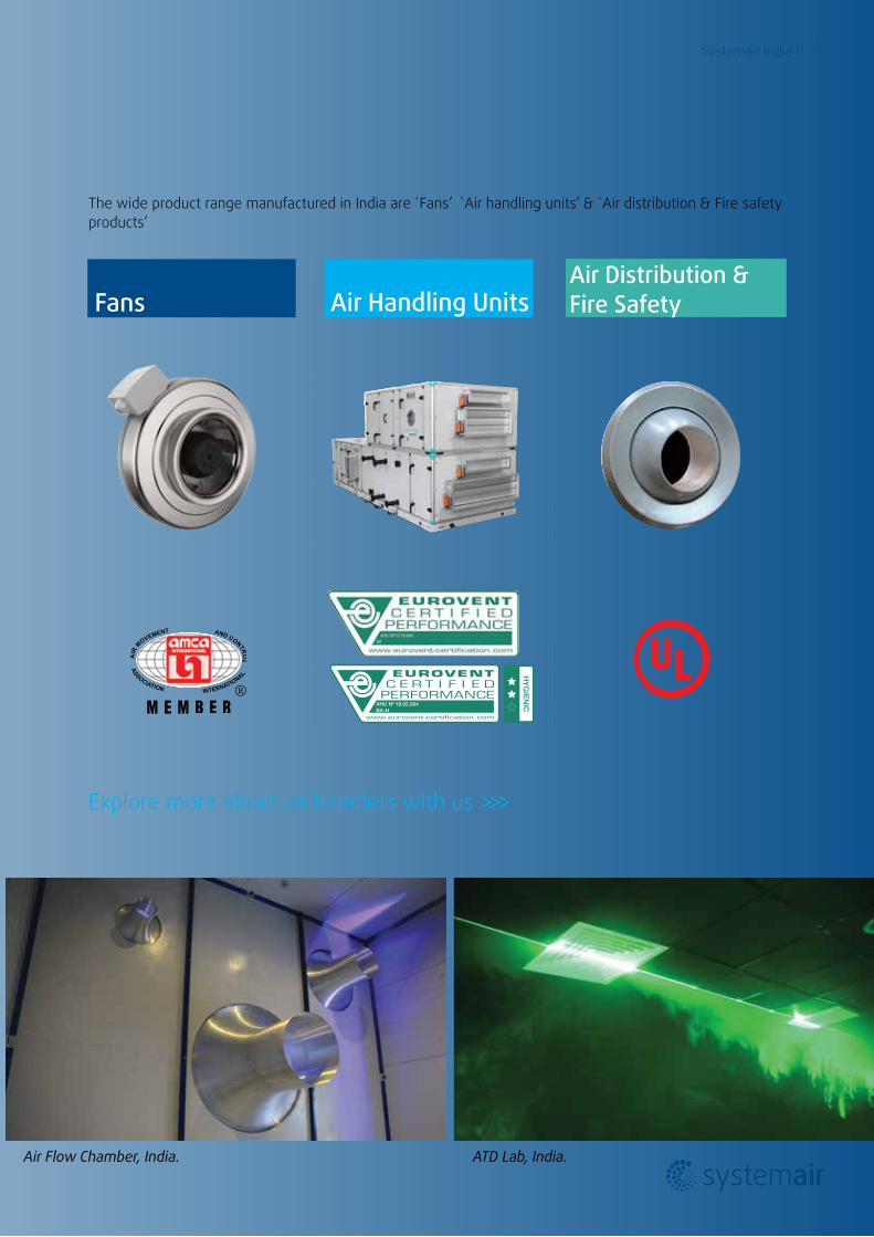
The wide product range manufactured in India are `Fans’ `Air handling units’ & `Air distribution & Fire safety products’
Explore more about air handlers with us >>>
AHU N0 18.02.004BA-H
HY
GIE
NIC
ATD Lab, India.Air Flow Chamber, India.
FansAir Distribution & Fire SafetyAir Handling Units
6 | Air handling units
5.56 11.11 16.67 22.22 27.78 33.33 38.89 44.44 50.00 55.55
m3/h
m3/s
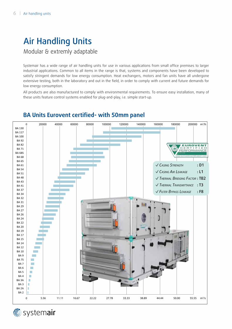
Systemair has a wide range of air handling units for use in various applications from small office premises to larger industrial applications. Common to all items in the range is that, systems and components have been developed to satisfy stringent demands for low energy consumption. Heat exchangers, motors and fan units have all undergone extensive testing, both in the laboratory and out in the field, in order to comply with current and future demands for low energy consumption.
All products are also manufactured to comply with environmental requirements. To ensure easy installation, many of these units feature control systems enabled for plug-and-play, i.e. simple start-up.
BA Units Eurovent certified- with 50mm panel
Air Handling UnitsModular & extremly adaptable
✓Casing strength : D1
✓Casing air Leakage : L1
✓ thermaL Bridging FaCtor : TB2
✓ thermaL transmittanCe : T3
✓ FiLter Bypass Leakage : F8
Air handling units | 7
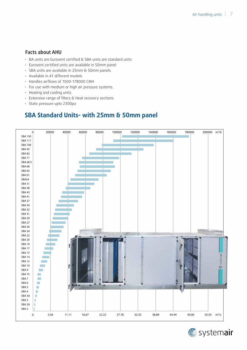
• BA units are Eurovent certified & SBA units are standard units• Eurovent certified units are available in 50mm panel• SBA units are available in 25mm & 50mm panels• Available in 41 different models• Handles airflows of 1000-178000 CMH• For use with medium or high air pressure systems.• Heating and cooling units• Extensive range of filters & Heat recovery sections• Static pressure upto 2300pa
Facts about AHU
5.56 11.11 16.67 22.22 27.78 33.33 38.89 44.44 50.00 55.55
m3/h
m3/s
SBA 2
SBA 2A
SBA 3 SBA 3A SBA 4 SBA 5 SBA 6 SBA 7
SBA 7S SBA 9 SBA 10 SBA 12 SBA 14 SBA 15
SBA 17 SBA 19
SBA 20 SBA 22 SBA 24 SBA 26 SBA 27
SBA 29SBA 31SBA 32SBA 34
SBA 37 SBA 41SBA 43SBA 48 SBA 51 SBA54 SBA 61 SBA 65 SBA 68 SBA 68 S SBA 71 SBA 82 SBA 92 SBA 100 SBA 117 SBA 130
SBA Standard Units- with 25mm & 50mm panel
8 | Air handling units
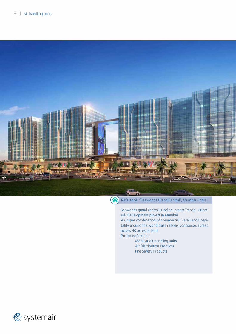
Seawoods grand central is India’s largest Transit –Orient-ed- Development project in Mumbai.A unique combination of Commercial, Retail and Hospi-tality around the world class railway concourse, spread across 40 acres of land.Products/Solution: Modular air handling units Air Distribution Products Fire Safety Products
Reference: “Seawoods Grand Central”, Mumbai -India
Air handling units | 9
Examples Of ApplicationsOur air handling units are designed in modules. The module can be configured for different applications to make up the heart of any air conditioning system. The flexibility makes it possible to optimize the air handling unit for specific requirement.
Comfort Solutions
Simple project implementation for expansion of existing premises or new buildings. Simplifies selection and planning and includes smart solutions for easier installation.
Extreme space-saving solutions and new connections for units that can also be split. Completely adaptable to satisfy all new demands. Compact air handling units are easier to transport and handle at the construction site.
Flexible Solutions
Flexible solutions with heat recovery and intelligent control functions that are easily adapted to suit current needs of different recovery systems and configurations.
Air humidifiers can be installed in air handling units, which makes it suitable for air cooling, water spray humidifier and scrubber applications.
Clean rooms can encompass numerous applications, everything from operating theatres to laboratories. Systemair’s range of air handling units can satisfy all requirements relating to healthcare, whether these have to do with air cleanliness, noise levels or demand control.
Compact Solutions
Integrated control systems. Our factory-integrated solutions are designed with various levels of equipment that can handle everything from the simplest requirement to the toughest demands.
Plug & Play Solutions
Industrial Solutions
Clean Room Solutions
10 | Air handling units
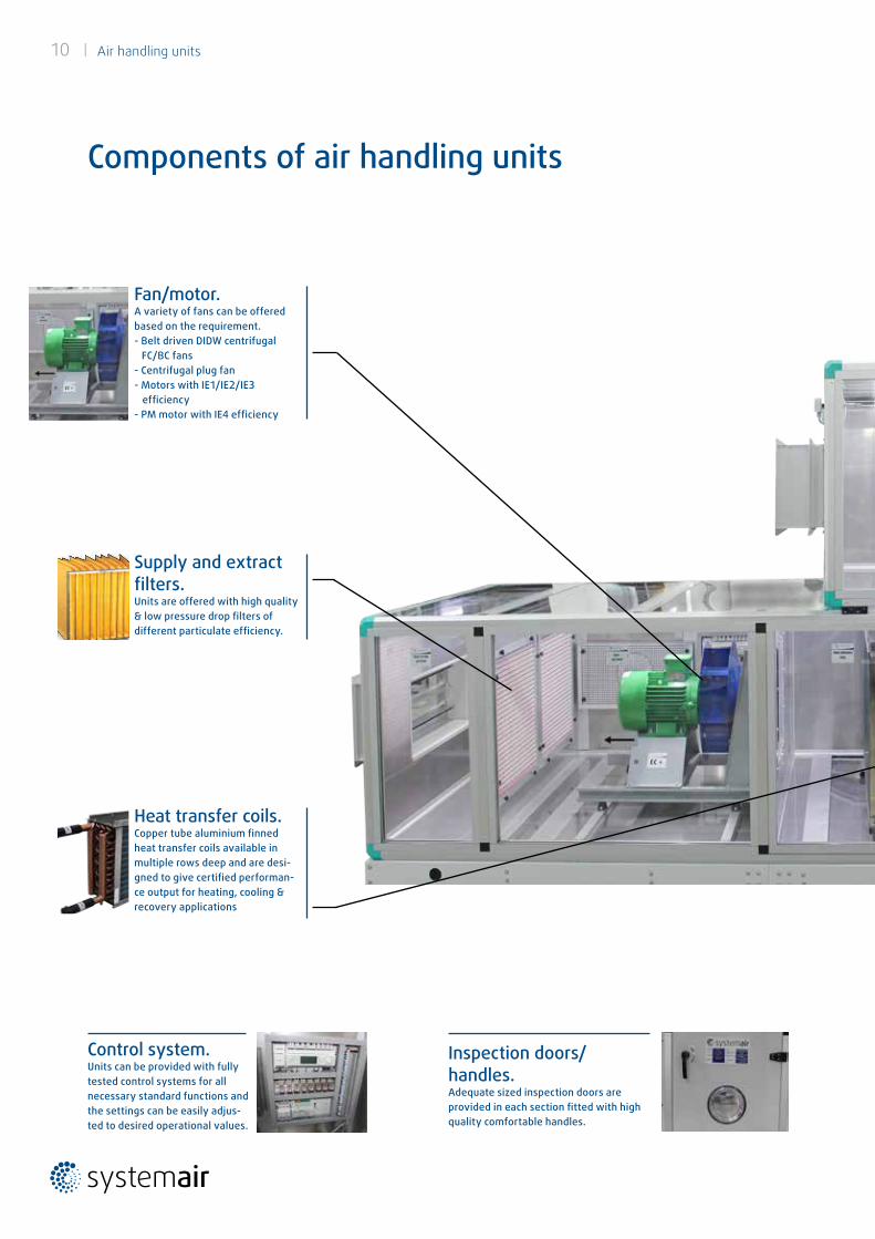
Components of air handling units
Fan/motor. A variety of fans can be offered based on the requirement.- Belt driven DIDW centrifugal FC/BC fans- Centrifugal plug fan- Motors with IE1/IE2/IE3 efficiency- PM motor with IE4 efficiency
Heat transfer coils.Copper tube aluminium finned heat transfer coils available in multiple rows deep and are desi-gned to give certified performan-ce output for heating, cooling & recovery applications
Supply and extract filters. Units are offered with high quality & low pressure drop filters of different particulate efficiency.
Inspection doors/handles. Adequate sized inspection doors are provided in each section fitted with high quality comfortable handles.
Control system. Units can be provided with fully tested control systems for all necessary standard functions and the settings can be easily adjus-ted to desired operational values.
Air handling units | 11
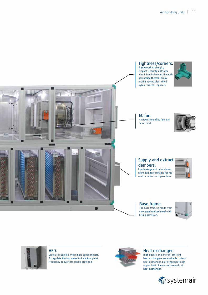
Heat exchanger. High quality and energy-efficientheat exchangers are available: rotary heat exchanger, plate type heat exch-anger, heat pipes or run around coil heat exchanger.
Base frame. The base frame is made from strong galvanized steel with lifting provision.
VFD.Units are supplied with single speed motors. To regulate the fan speed to its actual point, frequency converters can be provided.
Tightness/corners. Framework of airtight, elegant & sturdy extruded aluminium hollow profile with polyamide thermal break profile having glass filled nylon corners & spacers.
EC fan. A wide range of EC fans can be offered.
Supply and extract dampers. low-leakage extruded alumi-nium dampers suitable for ma-nual or motorised operations.
12 | Air handling units
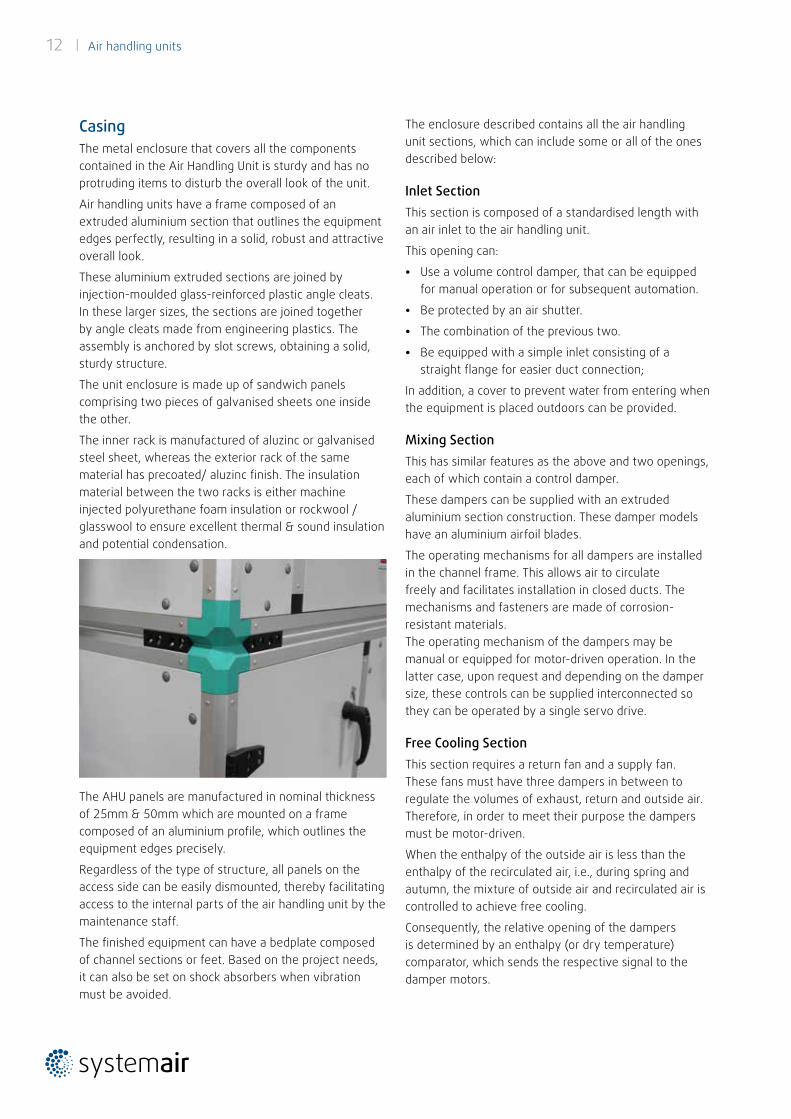
CasingThe metal enclosure that covers all the components contained in the Air Handling Unit is sturdy and has no protruding items to disturb the overall look of the unit.
Air handling units have a frame composed of an extruded aluminium section that outlines the equipment edges perfectly, resulting in a solid, robust and attractive overall look.
These aluminium extruded sections are joined by injection-moulded glass-reinforced plastic angle cleats.In these larger sizes, the sections are joined together by angle cleats made from engineering plastics. The assembly is anchored by slot screws, obtaining a solid, sturdy structure.
The unit enclosure is made up of sandwich panels comprising two pieces of galvanised sheets one inside the other.
The inner rack is manufactured of aluzinc or galvanised steel sheet, whereas the exterior rack of the same material has precoated/ aluzinc finish. The insulation material between the two racks is either machine injected polyurethane foam insulation or rockwool / glasswool to ensure excellent thermal & sound insulation and potential condensation.
The AHU panels are manufactured in nominal thickness of 25mm & 50mm which are mounted on a frame composed of an aluminium profile, which outlines the equipment edges precisely.
Regardless of the type of structure, all panels on the access side can be easily dismounted, thereby facilitating access to the internal parts of the air handling unit by the maintenance staff.
The finished equipment can have a bedplate composed of channel sections or feet. Based on the project needs, it can also be set on shock absorbers when vibration must be avoided.
The enclosure described contains all the air handling unit sections, which can include some or all of the ones described below:
Inlet SectionThis section is composed of a standardised length with an air inlet to the air handling unit.
This opening can:
• Use a volume control damper, that can be equipped for manual operation or for subsequent automation.
• Be protected by an air shutter.
• The combination of the previous two.
• Be equipped with a simple inlet consisting of a straight flange for easier duct connection;
In addition, a cover to prevent water from entering when the equipment is placed outdoors can be provided.
Mixing SectionThis has similar features as the above and two openings, each of which contain a control damper.
These dampers can be supplied with an extruded aluminium section construction. These damper models have an aluminium airfoil blades.
The operating mechanisms for all dampers are installed in the channel frame. This allows air to circulate freely and facilitates installation in closed ducts. The mechanisms and fasteners are made of corrosion-resistant materials.The operating mechanism of the dampers may be manual or equipped for motor-driven operation. In the latter case, upon request and depending on the damper size, these controls can be supplied interconnected so they can be operated by a single servo drive.
Free Cooling SectionThis section requires a return fan and a supply fan. These fans must have three dampers in between to regulate the volumes of exhaust, return and outside air. Therefore, in order to meet their purpose the dampers must be motor-driven.
When the enthalpy of the outside air is less than the enthalpy of the recirculated air, i.e., during spring and autumn, the mixture of outside air and recirculated air is controlled to achieve free cooling.
Consequently, the relative opening of the dampers is determined by an enthalpy (or dry temperature) comparator, which sends the respective signal to the damper motors.
Air handling units | 13
In order to ensure the minimum ventilation air required in cooling or heating seasons, the outside air inlet damper can be split into two sections (one motor-driven and another manual that remains fixed). The cross-section of the damper will be proportional to the minimum ventilation air flow.
This effect can also be achieved more economically by adjusting the stroke of the motor operating the outside air damper so it does not close completely.
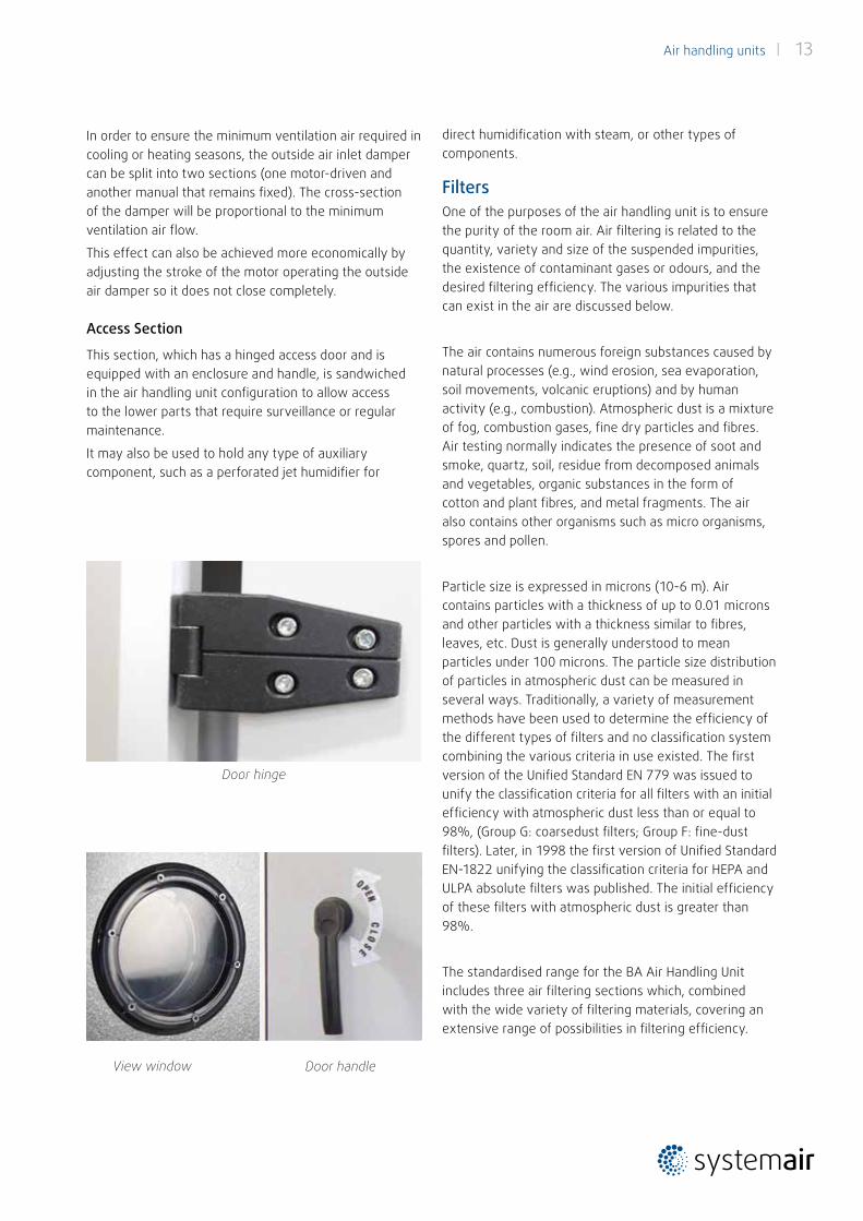
Access Section
This section, which has a hinged access door and is equipped with an enclosure and handle, is sandwiched in the air handling unit configuration to allow access to the lower parts that require surveillance or regular maintenance.
It may also be used to hold any type of auxiliary component, such as a perforated jet humidifier for
View window
Door hinge
Door handle
direct humidification with steam, or other types of components.
FiltersOne of the purposes of the air handling unit is to ensure the purity of the room air. Air filtering is related to the quantity, variety and size of the suspended impurities, the existence of contaminant gases or odours, and the desired filtering efficiency. The various impurities that can exist in the air are discussed below.
The air contains numerous foreign substances caused by natural processes (e.g., wind erosion, sea evaporation, soil movements, volcanic eruptions) and by human activity (e.g., combustion). Atmospheric dust is a mixture of fog, combustion gases, fine dry particles and fibres. Air testing normally indicates the presence of soot and smoke, quartz, soil, residue from decomposed animals and vegetables, organic substances in the form of cotton and plant fibres, and metal fragments. The air also contains other organisms such as micro organisms, spores and pollen.
Particle size is expressed in microns (10-6 m). Air contains particles with a thickness of up to 0.01 microns and other particles with a thickness similar to fibres, leaves, etc. Dust is generally understood to mean particles under 100 microns. The particle size distribution of particles in atmospheric dust can be measured in several ways. Traditionally, a variety of measurement methods have been used to determine the efficiency of the different types of filters and no classification system combining the various criteria in use existed. The first version of the Unified Standard EN 779 was issued to unify the classification criteria for all filters with an initial efficiency with atmospheric dust less than or equal to 98%, (Group G: coarsedust filters; Group F: fine-dust filters). Later, in 1998 the first version of Unified Standard EN-1822 unifying the classification criteria for HEPA and ULPA absolute filters was published. The initial efficiency of these filters with atmospheric dust is greater than 98%.
The standardised range for the BA Air Handling Unit includes three air filtering sections which, combined with the wide variety of filtering materials, covering an extensive range of possibilities in filtering efficiency.
14 | Air handling units
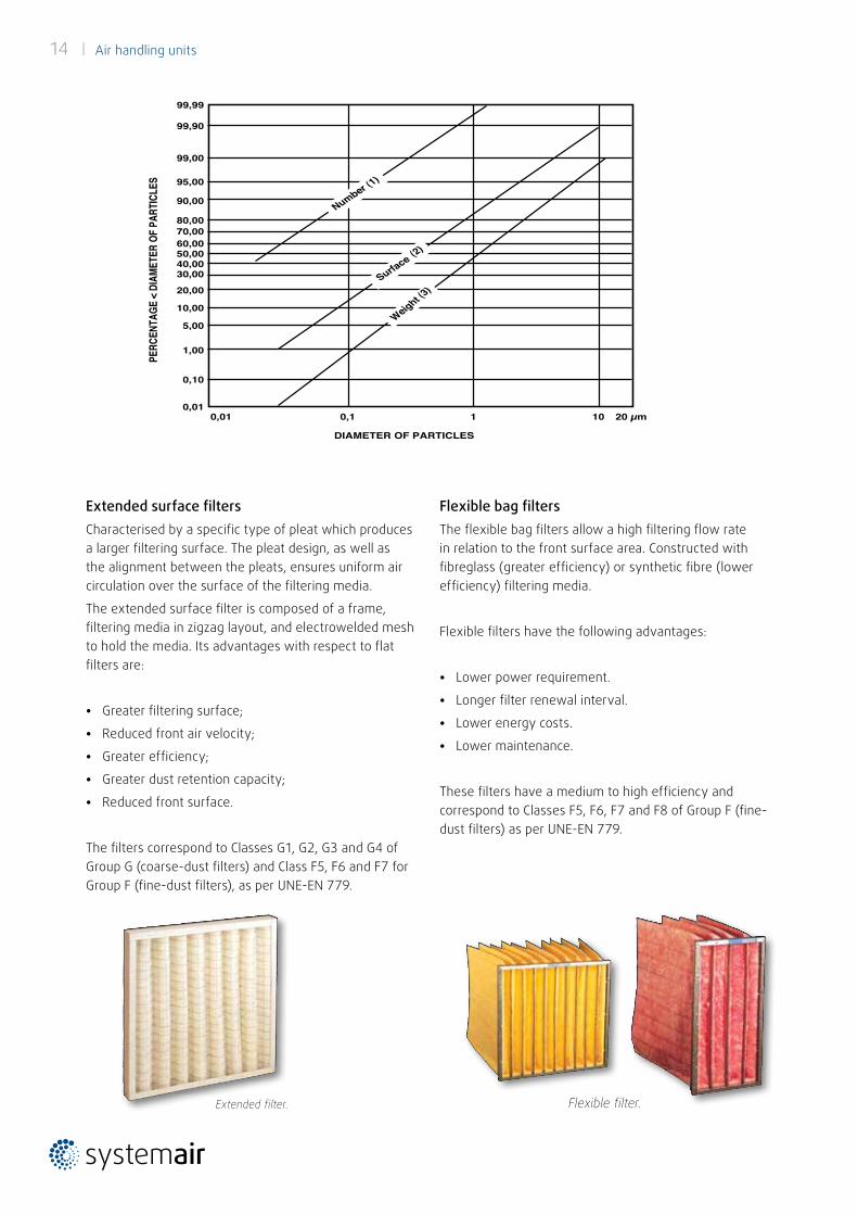
Flexible bag filtersThe flexible bag filters allow a high filtering flow rate in relation to the front surface area. Constructed with fibreglass (greater efficiency) or synthetic fibre (lower efficiency) filtering media.
Flexible filters have the following advantages:
• Lower power requirement.
• Longer filter renewal interval.
• Lower energy costs.
• Lower maintenance.
These filters have a medium to high efficiency and correspond to Classes F5, F6, F7 and F8 of Group F (fine-dust filters) as per UNE-EN 779.
Extended surface filtersCharacterised by a specific type of pleat which produces a larger filtering surface. The pleat design, as well as the alignment between the pleats, ensures uniform air circulation over the surface of the filtering media.
The extended surface filter is composed of a frame, filtering media in zigzag layout, and electrowelded mesh to hold the media. Its advantages with respect to flat filters are:
• Greater filtering surface;
• Reduced front air velocity;
• Greater efficiency;
• Greater dust retention capacity;
• Reduced front surface.
The filters correspond to Classes G1, G2, G3 and G4 of Group G (coarse-dust filters) and Class F5, F6 and F7 for Group F (fine-dust filters), as per UNE-EN 779.
Extended filter. Flexible filter.
Number (1)
DIAMETER OF PARTICLES
0,01 0,1 1 10 20 µm
99,99
99,90
99,00
95,00
90,00
80,0070,0060,0050,0040,0030,00
20,00
10,00
5,00
1,00
0,10
0,01
Surface (2)
Weight (3)
PERC
ENTA
GE <
DIAM
ETER
OF
PART
ICLE
S
Air handling units | 15
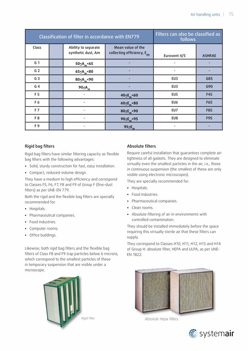
Absolute filtersRequire careful installation that guarantees complete air-tightness of all gaskets. They are designed to eliminate virtually even the smallest particles in the air, i.e., those in continuous suspension (the smallest of these are only visible using electronic microscopes).
They are specially recommended for:
• Hospitals.
• Food industries.
• Pharmaceutical companies.
• Clean rooms.
• Absolute filtering of air in environments with controlled contamination.
They should be installed immediately before the space requiring this virtually sterile air that these filters can supply.
They correspond to Classes H10, H11, H12, H13 and H14 of Group H: absolute filter, HEPA and ULPA, as per UNE-EN 1822.
Rigid bag filters
Rigid bag filters have similar filtering capacity as flexible bag filters with the following advantages:
• Solid, sturdy construction for fast, easy installation.
• Compact, reduced-volume design.
They have a medium to high efficiency and correspond to Classes F5, F6, F7, F8 and F9 of Group F (fine-dust filters) as per UNE-EN 779.
Both the rigid and the flexible bag filters are specially recommended for:
• Hospitals.
• Pharmaceutical companies.
• Food industries.
• Computer rooms.
• Office buildings.
Likewise, both rigid bag filters and the flexible bag filters of Class F8 and F9 trap particles below 6 microns, which correspond to the smallest particles of those in temporary suspension that are visible under a microscopic.
Absolute Hepa filters.
Classification of filter in accordance with EN779 Filters can also be classified as follows
Class Ability to separatesynthetic dust, Am
Mean value of thecollecting efficiency, Em Eurovent 4/5 ASHRAE
G 1 50<Am<65 - - -
G 2 65<Am<80 - - -
G 3 80<Am<90 - EU3 G85
G 4 90<Am- EU3 G90
F 5 - 40<Em<60 EU5 F45
F 6 - 60<Em<80 EU6 F65
F 7 - 80<Em<90 EU7 F85
F 8 - 90<Em<95 EU8 F95
F 9 - 95<Em- -
Rigid filter.
16 | Air handling units
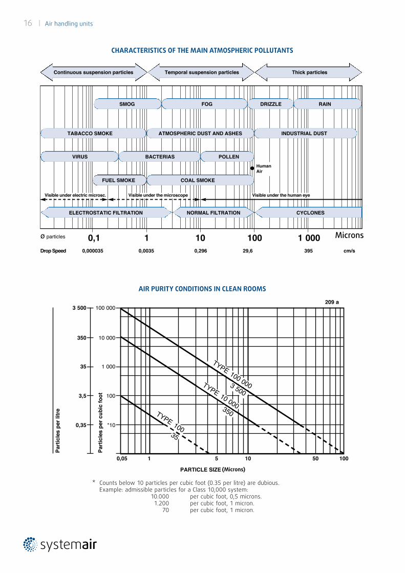
CHARACTERISTICS OF THE MAIN ATMOSPHERIC POLLUTANTS
AIR PURITY CONDITIONS IN CLEAN ROOMS
* Counts below 10 particles per cubic foot (0.35 per litre) are dubious.Example: admissible particles for a Class 10,000 system:
10.000 per cubic foot, 0,5 microns. 1.200 per cubic foot, 1 micron.
70 per cubic foot, 1 micron.
0,1 1 10 100 1 000ø particles MICRAS
Drop Speed 0,000035 0,0035 0,296 29,6 395 cm/s
Continuous suspension particles Temporal suspension particles Thick particles
SMOG
TABACCO SMOKE ATMOSPHERIC DUST AND ASHES INDUSTRIAL DUST
VIRUS BACTERIAS POLLEN
ELECTROSTATIC FILTRATION NORMAL FILTRATION CYCLONES
HumanAir
FUEL SMOKE COAL SMOKE
FOG DRIZZLE RAIN
Visible under electric microsc. Visible under the microscope Visible under the human eye
CONDICIONES DE LA PUREZA DEL AIRE EN SALAS LIMPIAS
PARTICLE SIZE (Micras)
209 a
0,05 1 5 10 50 100
100 000
10 000
1 000
100
*10
3 500
350
35
3,5
0,35
Part
icle
s pe
r litr
e
Part
icle
s pe
r cub
ic fo
ot
TYPE 100 000 TYPE 10 000
3 500
350 TYPE 10035
(Microns)
Microns
Air handling units | 17
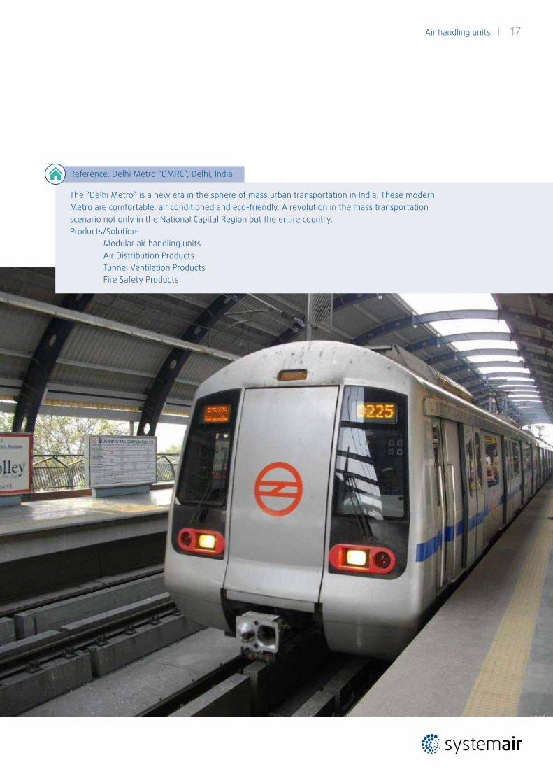
Reference: Delhi Metro “DMRC”, Delhi, India
The “Delhi Metro” is a new era in the sphere of mass urban transportation in India. These modern Metro are comfortable, air conditioned and eco-friendly. A revolution in the mass transportation scenario not only in the National Capital Region but the entire country. Products/Solution: Modular air handling units Air Distribution Products Tunnel Ventilation Products Fire Safety Products
18 | Air handling units
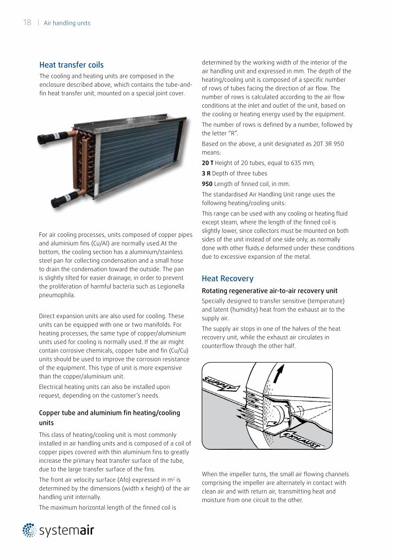
Heat transfer coilsThe cooling and heating units are composed in the enclosure described above, which contains the tube-and-fin heat transfer unit, mounted on a special joint cover.
For air cooling processes, units composed of copper pipes and aluminium fins (Cu/Al) are normally used.At the bottom, the cooling section has a aluminium/stainless steel pan for collecting condensation and a small hose to drain the condensation toward the outside. The pan is slightly tilted for easier drainage, in order to prevent the proliferation of harmful bacteria such as Legionella pneumophila.
Direct expansion units are also used for cooling. These units can be equipped with one or two manifolds. For heating processes, the same type of copper/aluminium units used for cooling is normally used. If the air might contain corrosive chemicals, copper tube and fin (Cu/Cu) units should be used to improve the corrosion resistance of the equipment. This type of unit is more expensive than the copper/aluminium unit.
Electrical heating units can also be installed upon request, depending on the customer’s needs.
Copper tube and aluminium fin heating/cooling units
This class of heating/cooling unit is most commonly installed in air handling units and is composed of a coil of copper pipes covered with thin aluminium fins to greatly increase the primary heat transfer surface of the tube, due to the large transfer surface of the fins.
The front air velocity surface (Afo) expressed in m2 is determined by the dimensions (width x height) of the air handling unit internally.
The maximum horizontal length of the finned coil is
Heat RecoveryRotating regenerative air-to-air recovery unit Specially designed to transfer sensitive (temperature) and latent (humidity) heat from the exhaust air to the supply air.
The supply air stops in one of the halves of the heat recovery unit, while the exhaust air circulates in counterflow through the other half.
When the impeller turns, the small air flowing channels comprising the impeller are alternately in contact with clean air and with return air, transmitting heat and moisture from one circuit to the other.
determined by the working width of the interior of the air handling unit and expressed in mm. The depth of the heating/cooling unit is composed of a specific number of rows of tubes facing the direction of air flow. The number of rows is calculated according to the air flow conditions at the inlet and outlet of the unit, based on the cooling or heating energy used by the equipment.
The number of rows is defined by a number, followed by the letter “R”.
Based on the above, a unit designated as 20T 3R 950 means:
20 T Height of 20 tubes, equal to 635 mm;
3 R Depth of three tubes
950 Length of finned coil, in mm.
The standardised Air Handling Unit range uses the following heating/cooling units:
This range can be used with any cooling or heating fluid except steam, where the length of the finned coil is slightly lower, since collectors must be mounted on both sides of the unit instead of one side only, as normally done with other fluids.e deformed under these conditions due to excessive expansion of the metal.
Air handling units | 19
heat recovery systems:
• Reduced heating plant power, minimising equipmentsizes in terms of boilers, fuel tank, circulating pumps,heat pipes and heating units.
• Reduced cooling plant size (compressors andcondensers or cooling towers), circulating pumps, pipegrid and cooling units. Savings in operating powerconsumption for heat and cold generation.
Any of the recovery systems mentioned in this section can be installed upon request only, as they are not included in the BA standardised range.
FansThis section is composed of a centrifugal fan with an anchor bedplate, drive and electric motor or plug-fan.
The centrifugal fan motor assembly is mounted on Silentbloc bushings and the discharge outlet is joined to the opening in the enclosure by means of a flexible fire retardant synthetic seal.
This allows the unit to run without external transmission of the small vibrations normally caused by fan motor assemblies.
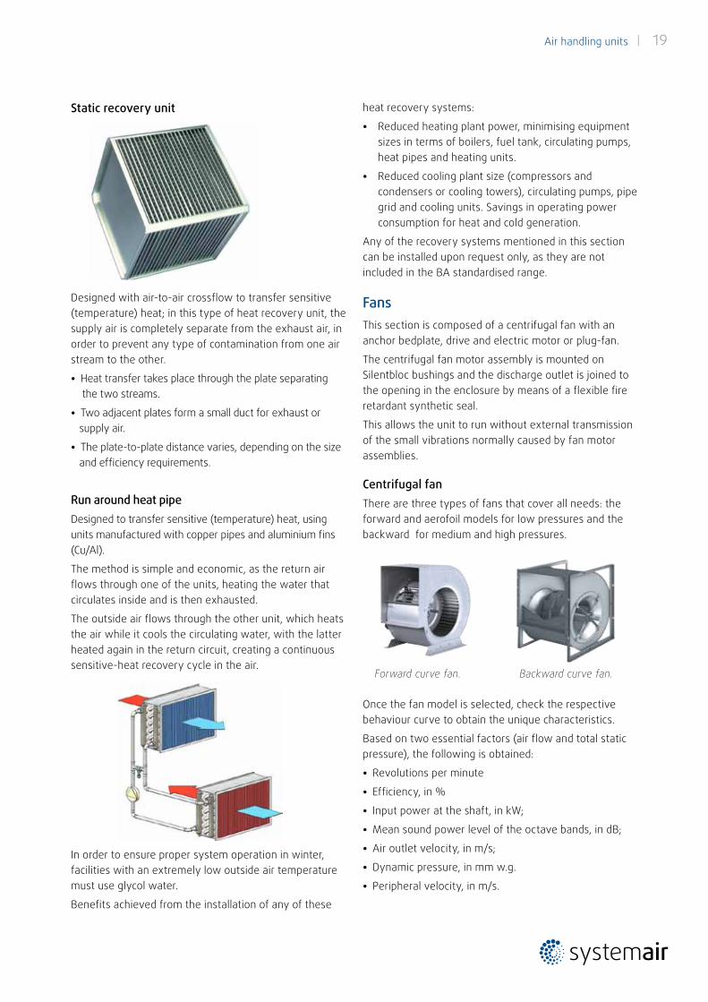
Centrifugal fanThere are three types of fans that cover all needs: the forward and aerofoil models for low pressures and the backward for medium and high pressures.
Once the fan model is selected, check the respective behaviour curve to obtain the unique characteristics.
Based on two essential factors (air flow and total static pressure), the following is obtained:
• Revolutions per minute
• Efficiency, in %
• Input power at the shaft, in kW;
• Mean sound power level of the octave bands, in dB;
• Air outlet velocity, in m/s;
• Dynamic pressure, in mm w.g.
• Peripheral velocity, in m/s.
Backward curve fan.Forward curve fan.
In order to ensure proper system operation in winter, facilities with an extremely low outside air temperature must use glycol water.
Benefits achieved from the installation of any of these
Static recovery unit
Designed with air-to-air crossflow to transfer sensitive (temperature) heat; in this type of heat recovery unit, the supply air is completely separate from the exhaust air, in order to prevent any type of contamination from one air stream to the other.
• Heat transfer takes place through the plate separatingthe two streams.
• Two adjacent plates form a small duct for exhaust orsupply air.
• The plate-to-plate distance varies, depending on the sizeand efficiency requirements.
Run around heat pipeDesigned to transfer sensitive (temperature) heat, using units manufactured with copper pipes and aluminium fins (Cu/Al).
The method is simple and economic, as the return air flows through one of the units, heating the water that circulates inside and is then exhausted.
The outside air flows through the other unit, which heats the air while it cools the circulating water, with the latter heated again in the return circuit, creating a continuous sensitive-heat recovery cycle in the air.
20 | Air handling units
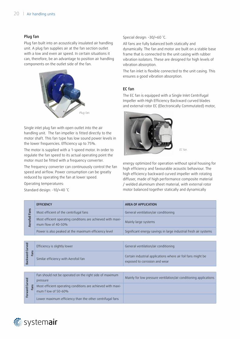
Special design: -30/+60 ˚C.
All fans are fully balanced both statically and dynamically. The fan and motor are built on a stable base frame that is connected to the unit casing with rubber vibration isolators. These are designed for high levels of vibration absorption.
The fan inlet is flexible connected to the unit casing. This ensures a good vibration absorption.
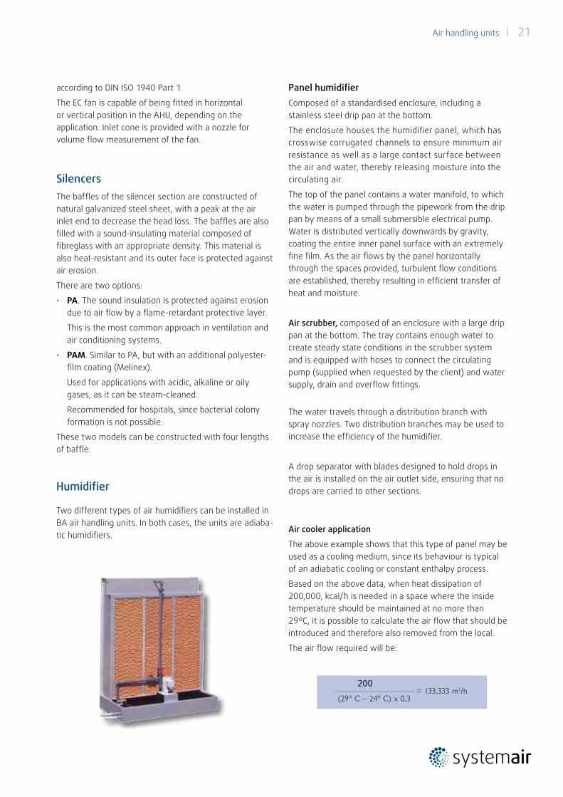
EC fanThe EC fan is equipped with a Single Inlet Centrifugal Impeller with High Efficiency Backward curved blades and external rotor EC (Electronically Commutated) motor,
EC fan.
energy optimized for operation without spiral housing for high efficiency and favourable acoustic behaviour. The high efficiency backward curved impeller with rotating diffuser, made of high performance composite material / welded aluminum sheet material, with external rotor motor balanced together statically and dynamically
Plug fanPlug fan built into an acoustically insulated air handling unit. A plug fan supplies air at the fan section outlet with a low and even air speed. In certain situations it can, therefore, be an advantage to position air handling components on the outlet side of the fan.
Single inlet plug fan with open outlet into the air handling unit. The fan impeller is fitted directly to the motor shaft. This fan type has low sound power levels in the lower frequencies. Efficiency up to 75%.
The motor is supplied with a 1-speed motor. In order to regulate the fan speed to its actual operating point the motor must be fitted with a frequency converter.
The frequency converter can continuously control the fan speed and airflow. Power consumption can be greatly reduced by operating the fan at lower speed.
Operating temperatures:
Standard design: -10/+40 ˚C
Aero
foil
Fans
EFFICIENCY AREA OF APPLICATION
Most efficient of the centrifugal fans General ventilation/air conditioning
Most efficient operating conditions are achieved with maxi-mum flow of 40-50%
Mainly large systems
Power is also peaked at the maximum efficiency level Significant energy savings in large industrial fresh air systems
Back
war
d Cu
rved
Fan
s
Efficiency is slightly lower General ventilation/air conditioning
Similar efficiency with Aerofoil fanCertain industrial applications where air foil fans might be exposed to corrosion and wear
Forw
ard
Curv
ed
Fan
s
Fan should not be operated on the right side of maximum pressure
Mainly for low pressure ventilation/air conditioning applications
Most efficient operating conditions are achieved with maxi-mum f low of 50-60%
Lower maximum efficiency than the other centrifugal fans
Plug fan.
Air handling units | 21
according to DIN ISO 1940 Part 1.
The EC fan is capable of being fitted in horizontal or vertical position in the AHU, depending on the application. Inlet cone is provided with a nozzle for volume flow measurement of the fan.
SilencersThe baffles of the silencer section are constructed of natural galvanized steel sheet, with a peak at the air inlet end to decrease the head loss. The baffles are also filled with a sound-insulating material composed of fibreglass with an appropriate density. This material is also heat-resistant and its outer face is protected against air erosion.
There are two options:
• PA. The sound insulation is protected against erosion due to air flow by a flame-retardant protective layer.
This is the most common approach in ventilation and air conditioning systems.
• PAM. Similar to PA, but with an additional polyester-film coating (Melinex).
Used for applications with acidic, alkaline or oily gases, as it can be steam-cleaned.
Recommended for hospitals, since bacterial colony formation is not possible.
These two models can be constructed with four lengths of baffle.
Humidifier
Two different types of air humidifiers can be installed in BA air handling units. In both cases, the units are adiaba-tic humidifiers.
Panel humidifierComposed of a standardised enclosure, including a stainless steel drip pan at the bottom.
The enclosure houses the humidifier panel, which has crosswise corrugated channels to ensure minimum air resistance as well as a large contact surface between the air and water, thereby releasing moisture into the circulating air.
The top of the panel contains a water manifold, to which the water is pumped through the pipework from the drip pan by means of a small submersible electrical pump.Water is distributed vertically downwards by gravity, coating the entire inner panel surface with an extremely fine film. As the air flows by the panel horizontally through the spaces provided, turbulent flow conditions are established, thereby resulting in efficient transfer of heat and moisture.
Air scrubber, composed of an enclosure with a large drip pan at the bottom. The tray contains enough water to create steady state conditions in the scrubber system and is equipped with hoses to connect the circulating pump (supplied when requested by the client) and water supply, drain and overflow fittings.
The water travels through a distribution branch with spray nozzles. Two distribution branches may be used to increase the efficiency of the humidifier.
A drop separator with blades designed to hold drops in the air is installed on the air outlet side, ensuring that no drops are carried to other sections.
Air cooler application
The above example shows that this type of panel may be used as a cooling medium, since its behaviour is typical of an adiabatic cooling or constant enthalpy process.
Based on the above data, when heat dissipation of 200,000, kcal/h is needed in a space where the inside temperature should be maintained at no more than 29ºC, it is possible to calculate the air flow that should be introduced and therefore also removed from the local.
The air flow required will be:
200
22 | Air handling units
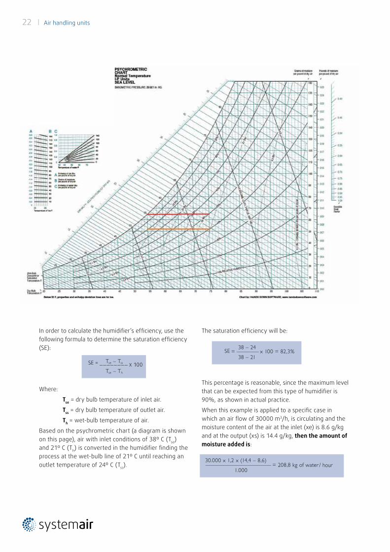
In order to calculate the humidifier’s efficiency, use the following formula to determine the saturation efficiency (SE):
Where:
Tse = dry bulb temperature of inlet air.
Tss = dry bulb temperature of outlet air.
Th = wet-bulb temperature of air.
Based on the psychrometric chart (a diagram is shown on this page), air with inlet conditions of 38º C (Tse) and 21º C (Th) is converted in the humidifier finding the process at the wet-bulb line of 21º C until reaching an outlet temperature of 24º C (Tss).
The saturation efficiency will be:
This percentage is reasonable, since the maximum level that can be expected from this type of humidifier is 90%, as shown in actual practice.
When this example is applied to a specific case in which an air flow of 30000 m3/h, is circulating and the moisture content of the air at the inlet (xe) is 8.6 g/kg and at the output (xs) is 14.4 g/kg, then the amount of moisture added is:
SE = ________ X 100
Air handling units | 23
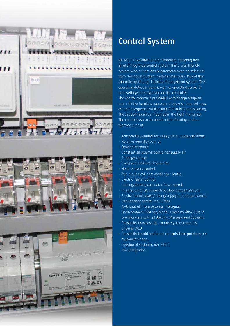
Control System
BA AHU is available with preinstalled, preconfigured & fully integrated control system. It is a user friendly system where functions & parameters can be selected from the inbuilt Human machine interface (HMI) of the controller or through building management system. The operating data, set points, alarms, operating status & time settings are displayed on the controller.The control system is preloaded with design tempera-ture, relative humidity, pressure drops etc., time settings & control sequence which simplifies field commissioning. The set points can be modified in the field if required.The control system is capable of performing various function such as
• Temperature control for supply air or room conditions.• Relative humidity control• Dew point control• Constant air volume control for supply air• Enthalpy control• Excessive pressure drop alarm• Heat recovery control• Run around coil heat exchanger control• Electric heater control• Cooling/heating coil water flow control• Integration of DX coil with outdoor condensing unit• Fresh/return/bypass/mixing/supply air damper control• Redundancy control for EC fans• AHU shut off from external fire signal• Open protocol (BACnet/Modbus over RS 485/LON) to communicate with all Building Management Systems.• Possibility to access the control system remotely through WEB• Possibility to add additional control/alarm points as per customer’s need• Logging of various parameters• VAV integration
24 | Air handling units
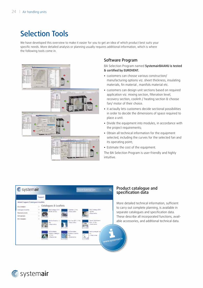
We have developed this overview to make it easier for you to get an idea of which product best suits your specific needs. More detailed analysis or planning usually requires additional information, which is where the following tools come in.
Selection Tools
Software ProgramBA Selection Program named SystemairBAAHU is tested & certified by EUROVENT.
• customers can chosse various construction/ manufacturing options viz. sheet thickness, insulating materials, fin material , manifols material etc.
• customers can design unit sections based on required application viz. mixing section, filteration level, recovery section, coolinh / heating section & choose fan/ motor of their choice.
• it actaully lets customers decide sectional possibilities in order to decide the dimensions of space required to place a unit.
• Divide the equipment into modules, in accordance with the project requirements;
• Obtain all technical information for the equipment selected, including the curves for the selected fan and its operating point;
• Estimate the cost of the equipment.
The BA Selection Program is user-friendly and highly intuitive.
Product catalogue and specification data
More detailed technical information, sufficient to carry out complete planning, is available in separate catalogues and specification data. These describe all incorporated functions, avail-able accessories, and additional technical data.
Air handling units | 25
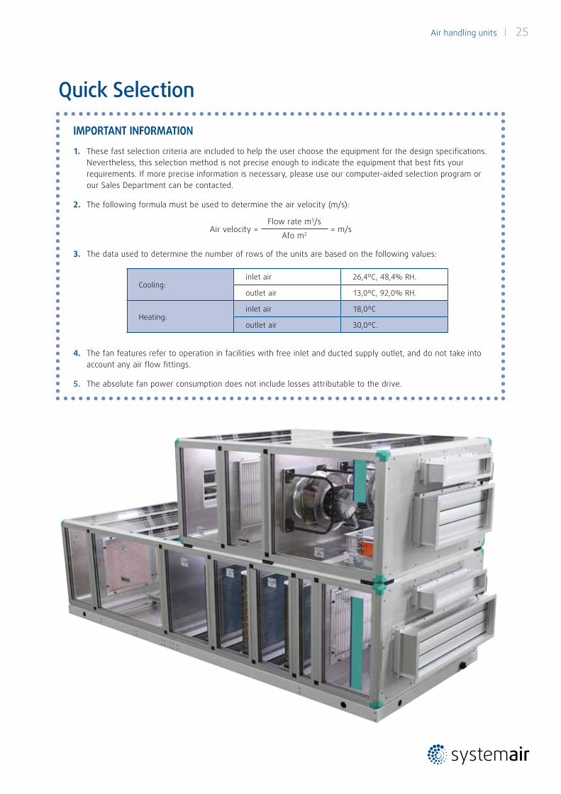
IMPORTANT INFORMATION
1. These fast selection criteria are included to help the user choose the equipment for the design specifications. Nevertheless, this selection method is not precise enough to indicate the equipment that best fits your requirements. If more precise information is necessary, please use our computer-aided selection program or our Sales Department can be contacted.
2. The following formula must be used to determine the air velocity (m/s):
Air velocity = Flow rate m3/s
Afo m2 = m/s
3. The data used to determine the number of rows of the units are based on the following values:
Cooling:inlet air 26,4ºC, 48,4% RH.
outlet air 13,0ºC, 92,0% RH.
Heating: inlet air 18,0ºC
outlet air 30,0ºC.
4. The fan features refer to operation in facilities with free inlet and ducted supply outlet, and do not take into account any air flow fittings.
5. The absolute fan power consumption does not include losses attributable to the drive.
Quick Selection
26 | Air handling units
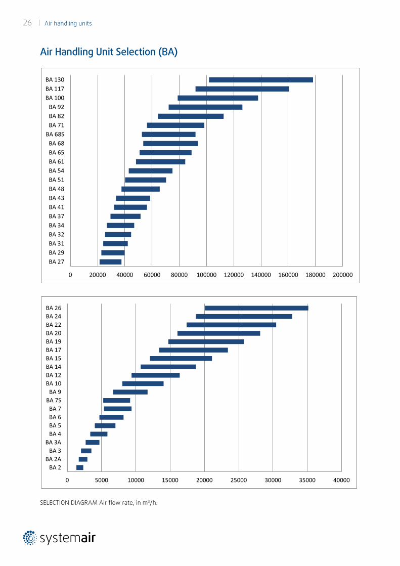
Air Handling Unit Selection (BA)
SELECTION DIAGRAM Air flow rate, in m3/h.
0 20000 40000 60000 80000 100000 120000 140000 160000 180000 200000
BA 27BA 29BA 31BA 32BA 34BA 37BA 41BA 43BA 48BA 51BA 54BA 61BA 65BA 68
BA 68SBA 71BA 82BA 92
BA 100BA 117BA 130
0 5000 10000 15000 20000 25000 30000 35000 40000
BA 2BA 2A
BA 3BA 3A
BA 4BA 5BA 6BA 7
BA 7SBA 9
BA 10BA 12BA 14BA 15BA 17BA 19BA 20BA 22BA 24BA 26
Air handling units | 27
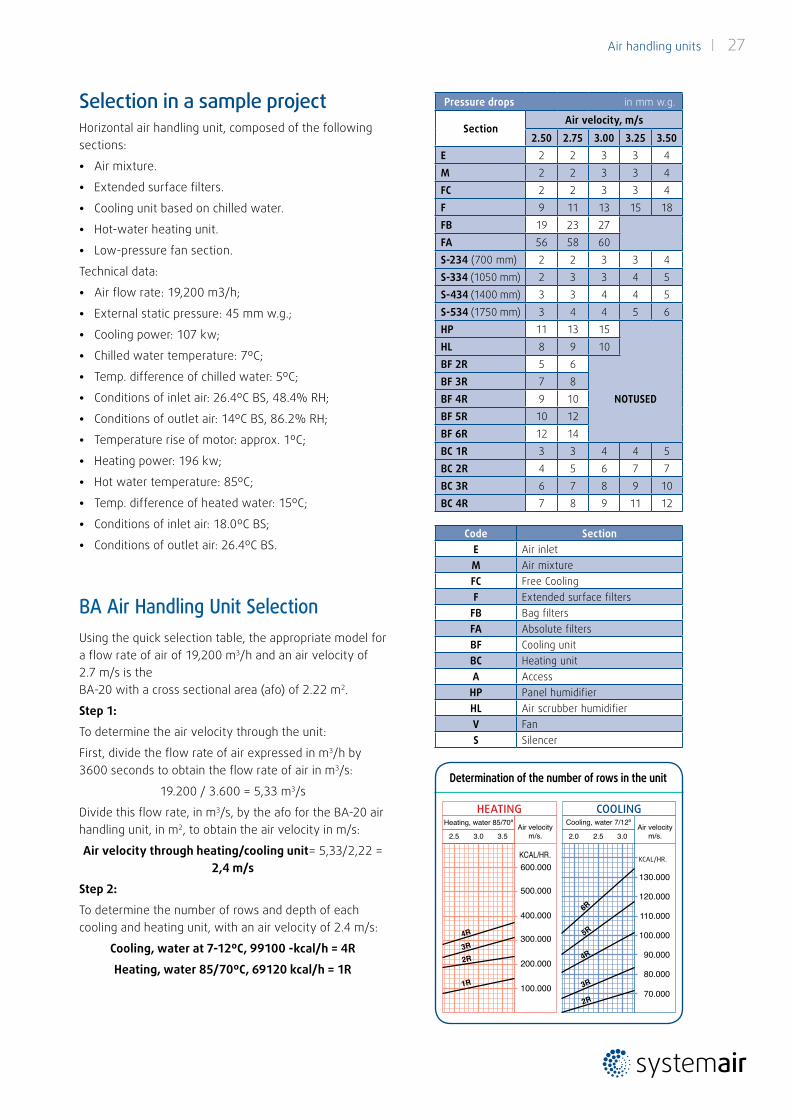
Determination of the number of rows in the unit
Horizontal air handling unit, composed of the following sections:
• Air mixture.
• Extended surface filters.
• Cooling unit based on chilled water.
• Hot-water heating unit.
• Low-pressure fan section.
Technical data:
• Air flow rate: 19,200 m3/h;
• External static pressure: 45 mm w.g.;
• Cooling power: 107 kw;
• Chilled water temperature: 7ºC;
• Temp. difference of chilled water: 5ºC;
• Conditions of inlet air: 26.4ºC BS, 48.4% RH;
• Conditions of outlet air: 14ºC BS, 86.2% RH;
• Temperature rise of motor: approx. 1ºC;
• Heating power: 196 kw;
• Hot water temperature: 85ºC;
• Temp. difference of heated water: 15ºC;
• Conditions of inlet air: 18.0ºC BS;
• Conditions of outlet air: 26.4ºC BS.
BA Air Handling Unit SelectionUsing the quick selection table, the appropriate model for a flow rate of air of 19,200 m3/h and an air velocity of 2.7 m/s is the BA-20 with a cross sectional area (afo) of 2.22 m2.
Step 1:
To determine the air velocity through the unit:
First, divide the flow rate of air expressed in m3/h by 3600 seconds to obtain the flow rate of air in m3/s:
19.200 / 3.600 = 5,33 m3/s
Divide this flow rate, in m3/s, by the afo for the BA-20 air handling unit, in m2, to obtain the air velocity in m/s:
Air velocity through heating/cooling unit= 5,33/2,22 = 2,4 m/s
Step 2:
To determine the number of rows and depth of each cooling and heating unit, with an air velocity of 2.4 m/s:
Cooling, water at 7-12ºC, 99100 -kcal/h = 4R
Heating, water 85/70ºC, 69120 kcal/h = 1R
Selection in a sample project
Heating, water 85/70º Air velocitym/s.2.5 3.0 3.5
KCAL/HR.600.000
500.000
400.000
300.000
200.000
100.000
2R
4R
3R
1R
Cooling, water 7/12º Air velocitym/s.2.0 2.5 3.0
FR/HR.130.000
120.000
110.000
100.000
90.000
80.000
70.000
4R
3R
6R
5R
2R
CALEFACCIÓN ENFRIAMIENTO
Pressure drops in mm w.g.
SectionAir velocity, m/s
2.50 2.75 3.00 3.25 3.50E 2 2 3 3 4M 2 2 3 3 4FC 2 2 3 3 4F 9 11 13 15 18FB 19 23 27FA 56 58 60S-234 (700 mm) 2 2 3 3 4S-334 (1050 mm) 2 3 3 4 5S-434 (1400 mm) 3 3 4 4 5S-534 (1750 mm) 3 4 4 5 6HP 11 13 15HL 8 9 10BF 2R 5 6
NOTUSEDBF 3R 7 8BF 4R 9 10BF 5R 10 12BF 6R 12 14BC 1R 3 3 4 4 5BC 2R 4 5 6 7 7BC 3R 6 7 8 9 10BC 4R 7 8 9 11 12
Code SectionE Air inletM Air mixtureFC Free CoolingF Extended surface filters
FB Bag filtersFA Absolute filtersBF Cooling unitBC Heating unitA Access
HP Panel humidifierHL Air scrubber humidifierV FanS Silencer
HEATING COOLING
KCAL/HR.
28 | Air handling units
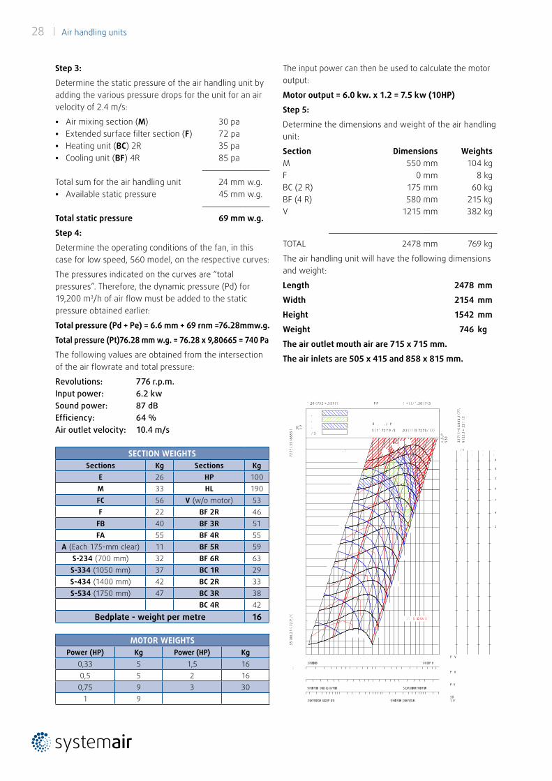
The input power can then be used to calculate the motor output:
Motor output = 6.0 kw. x 1.2 = 7.5 kw (10HP)
Step 5:
Determine the dimensions and weight of the air handling unit:
Section Dimensions WeightsM 550 mm 104 kgF 0 mm 8 kgBC (2 R) 175 mm 60 kgBF (4 R) 580 mm 215 kgV 1215 mm 382 kg
___________________________________
TOTAL 2478 mm 769 kg
The air handling unit will have the following dimensions and weight:
Length 2478 mm
Width 2154 mm
Height 1542 mm
Weight 746 kg
The air outlet mouth air are 715 x 715 mm.
The air inlets are 505 x 415 and 858 x 815 mm.
Step 3:
Determine the static pressure of the air handling unit by adding the various pressure drops for the unit for an air velocity of 2.4 m/s:
• Air mixing section (M) 30 pa• Extended surface filter section (F) 72 pa• Heating unit (BC) 2R 35 pa• Cooling unit (BF) 4R 85 pa
______________
Total sum for the air handling unit 24 mm w.g.• Available static pressure 45 mm w.g.
______________
Total static pressure 69 mm w.g.
Step 4:
Determine the operating conditions of the fan, in this case for low speed, 560 model, on the respective curves:
The pressures indicated on the curves are “total pressures”. Therefore, the dynamic pressure (Pd) for 19,200 m3/h of air flow must be added to the static pressure obtained earlier:
Total pressure (Pd + Pe) = 6.6 mm + 69 rnm =76.28mmw.g.
Total pressure (Pt)76.28 mm w.g. = 76.28 x 9,80665 = 740 Pa
The following values are obtained from the intersection of the air flowrate and total pressure:
Revolutions: 776 r.p.m.Input power: 6.2 kwSound power: 87 dBEfficiency: 64 %Air outlet velocity: 10.4 m/s
SECTION WEIGHTSSections Kg Sections Kg
E 26 HP 100M 33 HL 190FC 56 V (w/o motor) 53F 22 BF 2R 46
FB 40 BF 3R 51FA 55 BF 4R 55
A (Each 175-mm clear) 11 BF 5R 59S-234 (700 mm) 32 BF 6R 63
S-334 (1050 mm) 37 BC 1R 29S-434 (1400 mm) 42 BC 2R 33S-534 (1750 mm) 47 BC 3R 38
BC 4R 42Bedplate - weight per metre 16
MOTOR WEIGHTSPower (HP) Kg Power (HP) Kg
0,33 5 1,5 160,5 5 2 160,75 9 3 30
1 9
/ 5
:
.
:
.
:
2
4
7
0
2
5
8
.
:
* , 5 , P
5 3 0
3 5 ( 6 6 , 2 1 ( 7 2 7 $ / (
7 2 7 $ / 3 5 ( 6 6 8 5 (
' , $ 0 ( 7 5 2 * , 5 $ 1 7 ( : + ( ( / ' , $ 0 ( 7 ( 5 P P $ ' +
.
.
.
/ 5
;
9 R O X P H 3 R U W D W D
9 H O R F L W D D U L D L Q X V F L W D $ L U R X W O H W Y H O R F L W ¥
3 U H V V L R Q H G L Q D P L F D 9 H O R F L W ¥ 3 U H V V X U H
/ H S U H V W D ] L R Q L L Q G L F D W H V L U L I H U L V F R Q R D G L Q V W D O O D ] L R Q H % D V S L U D ] L R Q H 3 H U I R U P D Q F H V K R Z Q L V I R U L Q V W D O O D W L R Q W ¥ S H % I U H H L Q O H W O L E H U D P D Q G D W D F D Q D O L ] ] D W D H Q R Q W H Q J R Q R F R Q W R G L H Y H Q W X D O L G X F W H G R X W O H W D Q G G R H V Q W L Q F O X G H W K H H I I H F W V R I D F F H V V R U L Q H O I O X V V R G D U L D D S S X U W H Q D Q F H V L Q W K H D L U V W U H D P / D S R W H Q ] D D V V R U E L W D Q R Q L Q F O X G H O H S H U G L W H G H O O D W U D V P L V V L R Q H 3 R Z H U U D W L Q J N : G R H V Q W L Q F O X G H G U L Y H O R V V H V / D & H U W L I L F D ] L R Q H $ 0 & $ V L U L I H U L V F H D O O H V R O H S U H V W D ] L R Q L D H U D X O L F K H 7 K H $ 0 & $ & H U W L I L H G 5 D W L Q J V 6 H D O D S S O L H V W R $ L U 3 H U I R U P D Q F H R Q O ¥
. :
P V
3 D
1 P
5 ( 1 ' 7 2 7 9 / $ , 0 3 ( / / ( 5 7 2 7 $ / ( ) )
P K
P V
3 D 1 P
/ : $ L Q G % $
U . J P
3 2 7 ( 1 = $ & 8 6 & , 1 ( 7 7 ,
% ( $ 5 , 1 * 3 2 : ( 5
Air handling units | 29
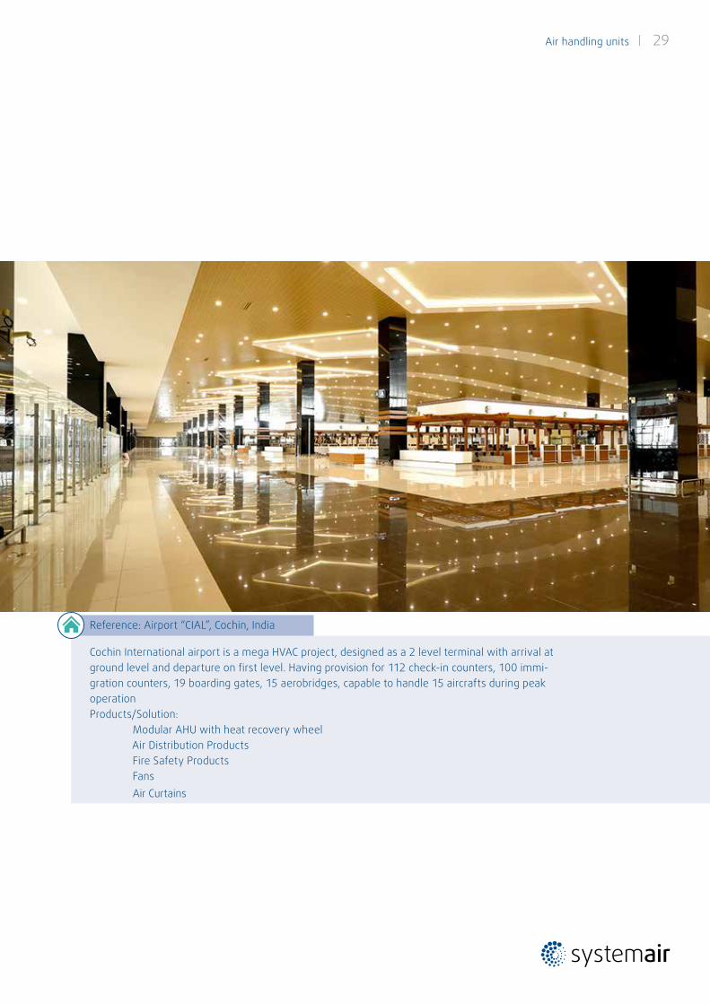
Reference: Airport “CIAL”, Cochin, India
Cochin International airport is a mega HVAC project, designed as a 2 level terminal with arrival at ground level and departure on first level. Having provision for 112 check-in counters, 100 immi-gration counters, 19 boarding gates, 15 aerobridges, capable to handle 15 aircrafts during peak operation Products/Solution: Modular AHU with heat recovery wheel Air Distribution Products Fire Safety Products Fans Air Curtains
30 | Air handling units
ROTATING HEAT EXCHANGER SIZE
Unit Type/
Nomenclature
Panel
ThicknessDim. 2 2A 3 3A 4 5 6 7S 7 9 10 12 14 15 17 19 20 22 24
Panel 25width 874 915 958 1004 1128 1229 1281 - 1430 1430 1559 1625 1625 1765 1846 2000 2154 2405 2405
height 1246 1550 1550 1850 1850 1850 1880 - 1880 2358 2358 2668 2968 2984 2984 2984 2984 3348 3348
Panel 50width 874 915 958 1004 1128 1229 1281 - 1430 1430 1559 1625 1625 1765 1846 2000 2154 2405 2405
height 1246 1550 1550 1850 1850 1850 1880 - 1880 2358 2358 2668 2968 2984 2984 2984 2984 3348 3348
C1V
25Length 2805 2805 2805 2980 2980 2980 2980 - 2980 2980 3330 3330 3330 3330 3565 3740 3740 3740 3740
Weight 394 435 454 565 607 641 668 - 727 824 1049 1178 1312 1392 1592 1748 1837 2045 2080
50Length 2865 2865 2865 2865 2865 2865 3040 - 3040 3040 3215 3390 3565 3390 3565 3565 3740 3740 3740
Weight 409 453 468 573 616 647 742 - 806 964 1069 1221 1423 1442 1643 1732 1895 2113 2148
C2V
25Length 3330 3330 3330 3330 3330 3505 3505 - 3505 3505 3680 3855 3855 3855 4090 4090 4265 4265 4265
Weight 426 476 489 561 605 696 728 - 799 907 1116 1274 1417 1567 1713 1809 1977 2203 2243
50Length 3390 3390 3390 3390 3390 3565 3565 - 3565 3565 3740 3915 3915 3915 4090 4090 4265 4265 4265
Weight 442 495 509 584 629 725 757 - 875 1032 1157 1321 1468 1621 1768 1867 2040 2277 2317
C3V
25Length 3330 3330 3330 3680 3680 3680 3680 - 3680 3680 3855 4030 4030 4030 4265 4265 4440 4440 4440
Weight 422 468 487 598 659 700 752 - 816 916 1076 1226 1329 1444 1645 1717 1895 2109 2144
50Length 3390 3390 3390 3740 3740 3740 3740 - 3740 3740 3915 4090 4090 4090 4265 4265 4440 4440 4440
Weight 439 487 507 623 686 741 781 - 848 953 1116 1272 1378 1497 1699 1774 1957 2181 2216
C4V
25Length 3855 3855 3855 4030 4030 4205 4205 - 4205 4205 4205 4555 4555 4555 4790 4615 4965 4965 4965
Weight 454 509 522 594 657 755 812 - 888 999 1143 1322 1434 1619 1766 1778 2035 2267 2307
50Length 3915 3915 3915 4265 4265 4440 4265 - 4265 4265 4440 4615 4440 4615 4790 4790 4965 4965 4965
Weight 472 529 548 634 699 819 796 - 917 1021 1204 1372 1423 1676 1824 1909 2102 2345 2385
C5V
25Length 3330 3330 3330 3680 3680 3680 3680 - 3680 3680 3855 4030 4030 4030 4265 4265 4440 4440 4440
Weight 436 482 502 615 677 718 770 - 836 938 1098 1250 1341 1518 1659 1731 1910 2125 2160
50Length 3390 3390 3390 3740 3740 3740 3740 - 3740 3740 3915 4090 4090 4090 4265 4265 4440 4440 4440
Weight 453 503 523 640 704 747 801 - 869 976 1140 1298 1392 1511 1714 1789 1972 2198 2233
C6V
25Length 3855 3855 3855 4030 4030 4205 4205 - 4205 4205 4205 4555 4555 4555 4790 4615 4965 4965 4965
Weight 468 523 537 611 675 773 830 - 908 1021 1165 1346 1446 1693 1780 1792 2050 2283 2323
50Length 3915 3915 3915 4265 4265 4440 4265 - 4265 4265 4440 4615 4440 4615 4790 4790 4965 4965 4965
Weight 486 545 564 651 717 825 816 - 938 1044 1228 1398 1437 1690 1839 1924 2117 2362 2402
Dimensions in mm. Weight in kgs.
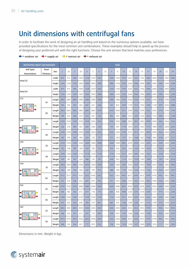
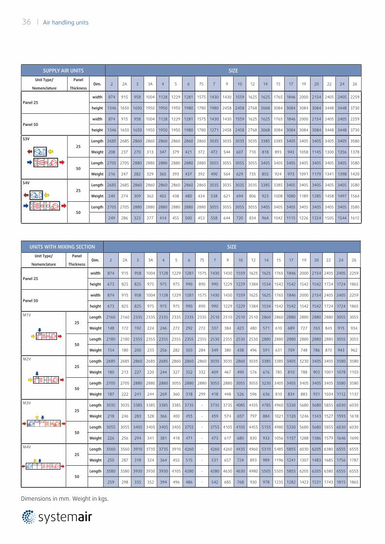
In order to facilitate the work of designing an air handling unit based on the numerous options available, we have provided specifications for the most common unit combinations. These examples should help to speed up the process of designing your preferred unit with the right functions. Choose the unit version that best matches your preferences.
Unit dimensions with centrifugal fans
= outdoor air = supply air = extract air = exhaust air
Air handling units | 31
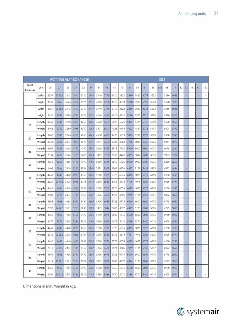
ROTATING HEAT EXCHANGER SIZEPanel
ThicknessDim. 26 27 29 31 32 34 37 41 43 48 51 54 61 65 68S 68 71 82 92 100 117 130
width 2259 2335.5 2412 2412 2710 2744 2710 2770 2710 2822 2850 2822 3078 3232 - 3386 3685 - - - - -
height 3630 3653 3676 4250 3676 3676 4060 4250 4910 4910 5220 5520 5520 5520 - 5520 5520 - - - - -
width 2259 2335.5 2412 2412 2710 2744 2710 2770 2710 2822 2850 2822 3078 3232 - 3386 3685 - - - - -
height 3630 3653 3676 4250 3676 3676 4060 4250 4910 4910 5220 5520 5520 5520 - 5520 5520 - - - - -
25Length 3740 3740 3740 4265 4265 4265 4500 4675 5025 5025 5375 5375 5375 5550 - 5550 5550 - - - - -
Weight 2165 2252 2339 2985 3030 3061 3301 3507 4028 4144 4622 4887 5278 5437 - 5604 6392 - - - - -
50Length 3740 3740 3740 4265 4265 4265 4500 4675 4675 5025 5375 5375 5375 5550 - 5550 5550 - - - - -
Weight 2233 2323 2413 3073 3090 3149 3317 3609 3786 4263 4755 5024 5335 5626 - 6261 6579 - - - - -
25Length 4265 4265 4265 4790 4790 4790 5200 5375 5375 5725 5900 5900 5900 6075 - 6075 6250 - - - - -
Weight 2334 2429 2524 3185 3206 3271 3467 3768 3953 4442 4835 5037 5283 5696 - 5953 6717 - - - - -
50Length 4265 4265 4265 4790 4790 4790 5200 5375 5550 5725 5900 5900 5900 6075 - 6250 6250 - - - - -
Weight 2408 2506 2604 3280 3301 3366 3571 3879 4305 4570 4972 5178 5433 5855 - 6577 6894 - - - - -
25Length 4440 4440 4440 4965 4965 5140 5200 5375 5375 6075 6075 6075 6075 6250 - 6250 6250 - - - - -
Weight 2229 2317.5 2406 3056 3073 3173 3296 3583 3755 4574 4706 4973 5200 5626 - 5926 6491 - - - - -
50Length 4440 4440 4440 4965 4965 5140 5200 5375 5725 6075 6075 6075 6075 6250 - 6250 6250 - - - - -
Weight 2302 2393 2484 3149 3165 3267 3396 3690 4156 4705 4919 5116 5352 5787 - 6092 6669 - - - - -
25Length 4965 4965 4965 5490 5490 5665 5900 6075 5725 6775 6600 6600 6600 6775 - 6775 6950 - - - - -
Weight 2398 2494.5 2591 3256 3249 3383 3462 3844 3680 4872 4919 5123 5205 5885 - 6275 6816 - - - - -
50Length 4965 4965 4965 5490 5490 5665 5900 6075 6600 6775 6600 6600 6600 6775 - 6950 6950 - - - - -
Weight 2477 2576 2675 3356 3376 3484 3650 3960 4675 5012 5136 5270 5450 6016 - 6408 6984 - - - - -
25Length 4440 4440 4440 4965 4965 5140 5200 5375 5375 6075 6075 6075 6075 6250 - 6250 6250 - - - - -
Weight 2245 2325.5 2406 3056 3101 3173 3296 3559 3755 4574 4781 4973 5200 5626 - 5926 6491 - - - - -
50Length 4440 4440 4440 4965 4965 5140 5200 5375 5375 6075 6075 6075 6075 6250 - 6250 6250 - - - - -
Weight 2319 2401.5 2484 3149 3165 3267 3396 3666 3871 4705 4919 5116 5352 5787 - 6092 6669 - - - - -
25Length 4965 4965 4965 5490 5490 5665 5900 6075 5725 6775 6600 6600 6600 6775 - 6775 6950 - - - - -
Weight 2414 2502.5 2591 3256 3277 3383 3462 3820 3680 4872 4994 5123 5205 5885 - 6275 6816 - - - - -
50Length 4965 4965 4965 5490 5490 5665 5900 6075 6250 6775 6600 6600 6600 6775 - 6950 6950 - - - - -
Weight 2494 2584.5 2675 3356 3376 3484 3650 3936 4390 5012 5136 5270 5450 6016 - 6408 6984 - - - - -
Dimensions in mm. Weight in kgs.
32 | Air handling units
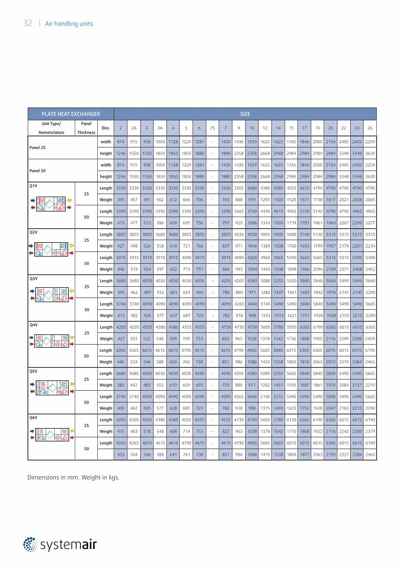
Dimensions in mm. Weight in kgs.
PLATE HEAT EXCHANGER SIZE
Unit Type/
Nomenclature
Panel
ThicknessDim. 2 2A 3 3A 4 5 6 7S 7 9 10 12 14 15 17 19 20 22 24 26
Panel 25width 874 915 958 1004 1128 1229 1281 - 1430 1430 1559 1625 1625 1765 1846 2000 2154 2405 2405 2259
height 1246 1550 1550 1850 1850 1850 1880 - 1880 2358 2358 2668 2968 2984 2984 2984 2984 3348 3348 3630
Panel 50width 874 915 958 1004 1128 1229 1281 - 1430 1430 1559 1625 1625 1765 1846 2000 2154 2405 2405 2259
height 1246 1550 1550 1850 1850 1850 1880 - 1880 2358 2358 2668 2968 2984 2984 2984 2984 3348 3348 3630
Q1V
25Length 3330 3330 3330 3330 3330 3330 3330 - 3330 3505 3680 4380 4380 4555 4615 4790 4790 4790 4790 4790
Weight 395 457 491 562 612 666 706 - 765 888 979 1293 1403 1525 1571 1738 1817 2021 2038 2065
50Length 3390 3390 3390 3390 3390 3390 3390 - 3390 3565 3740 4440 4615 4965 5140 5140 4790 4790 4965 4965
Weight 413 477 513 586 639 695 736 - 797 925 1006 1343 1503 1719 1781 1961 1964 2207 2299 2277
Q2V
25Length 3855 3855 3855 3680 3680 3855 3855 - 3855 4030 4030 4905 4905 5080 5140 5140 5315 5315 5315 5315
Weight 427 498 526 558 610 721 766 - 837 971 1046 1389 1508 1700 1692 1799 1957 2179 2201 2234
50Length 3915 3915 3915 3915 3915 4090 3915 - 3915 4090 4265 4965 4965 5490 5665 5665 5315 5315 5490 5490
Weight 446 519 554 597 652 773 751 - 866 993 1094 1443 1548 1898 1906 2096 2109 2371 2468 2452
Q3V
25Length 3680 3680 4030 4030 4030 4030 4030 - 4205 4205 4380 5080 5255 5430 5840 5840 5840 5490 5490 5840
Weight 395 462 487 552 601 654 693 - 780 880 971 1282 1437 1561 1687 1842 1976 2141 2145 2290
50Length 3740 3740 4090 4090 4090 4090 4090 - 4090 4265 4440 5140 5490 5490 5840 5840 5490 5490 5490 5665
Weight 413 482 505 577 637 687 723 - 782 918 998 1333 1513 1621 1751 1928 1928 2155 2215 2290
Q4V
25Length 4205 4205 4555 4380 4380 4555 4555 - 4730 4730 4730 5605 5780 5955 6365 6190 6365 6015 6015 6365
Weight 427 503 522 548 599 709 753 - 852 963 1038 1378 1542 1736 1808 1903 2116 2299 2308 2459
50Length 4265 4265 4615 4615 4615 4790 4615 - 4615 4790 4965 5665 5840 6015 6365 6365 6015 6015 6015 6190
Weight 446 524 546 588 650 765 738 - 851 986 1086 1433 1558 1800 1876 2063 2073 2319 2384 2465
Q5V
25Length 3680 3680 4030 4030 4030 4030 4030 - 4030 4205 4380 5080 5255 5605 5840 5840 5840 5490 5490 5665
Weight 383 442 483 552 610 659 693 - 750 880 971 1282 1437 1595 1687 1861 1976 2084 2137 2210
50Length 3740 3740 4090 4090 4090 4090 4090 - 4090 4265 4440 5140 5315 5490 5490 5490 5840 5490 5490 5665
Weight 400 462 505 577 628 683 723 - 782 918 998 1315 1493 1625 1752 1928 2047 2163 2215 2290
Q6V
25Length 4205 4205 4555 4380 4380 4555 4555 - 4555 4730 4730 5605 5780 6130 6365 6190 6365 6015 6015 6190
Weight 415 483 518 548 608 714 753 - 822 963 1038 1378 1542 1770 1808 1922 2116 2242 2300 2379
50Length 4265 4265 4615 4615 4615 4790 4615 - 4615 4790 4965 5665 5665 6015 6015 6015 6365 6015 6015 6190
433 504 546 588 641 761 738 - 851 986 1086 1415 1538 1804 1877 2063 2192 2327 2384 2465
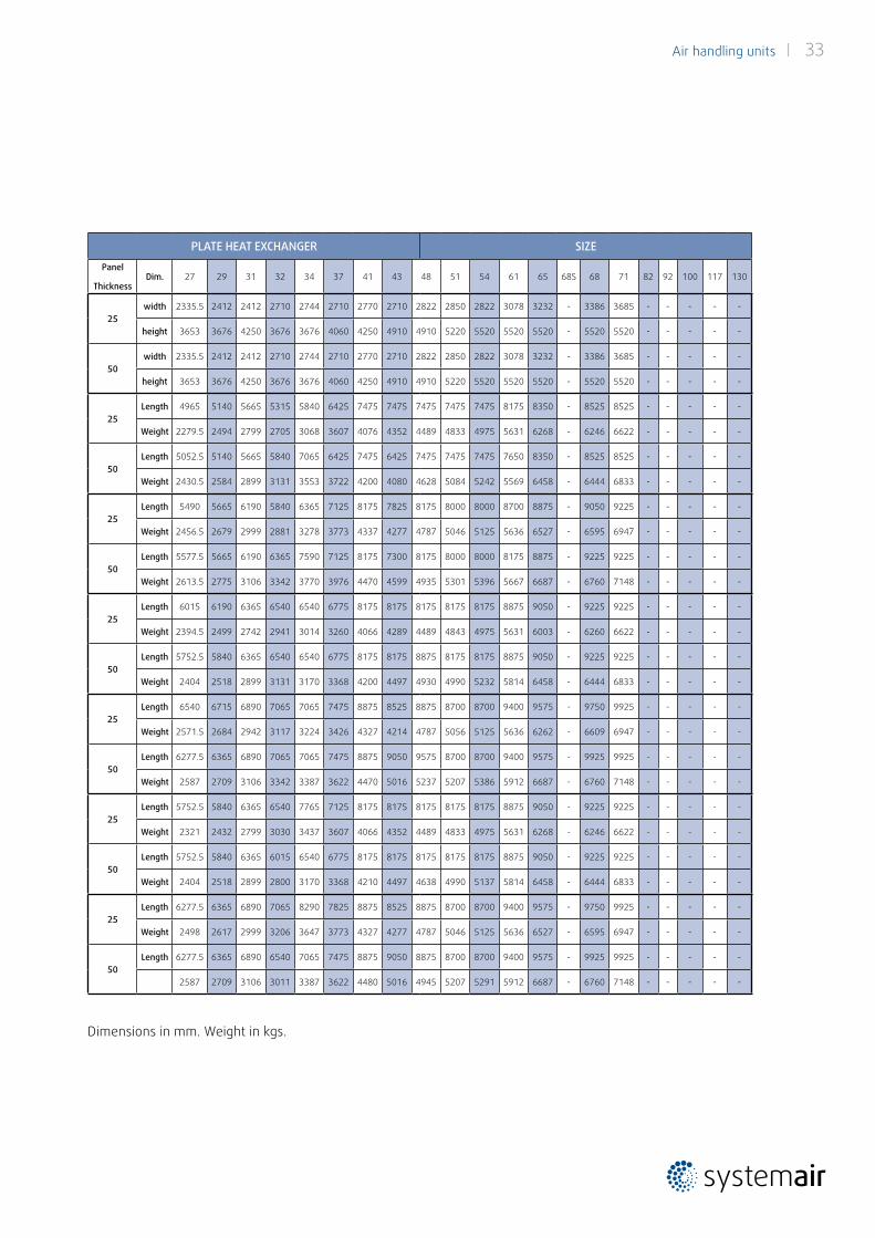
Air handling units | 33
PLATE HEAT EXCHANGER SIZE
Panel
ThicknessDim. 27 29 31 32 34 37 41 43 48 51 54 61 65 68S 68 71 82 92 100 117 130
25width 2335.5 2412 2412 2710 2744 2710 2770 2710 2822 2850 2822 3078 3232 - 3386 3685 - - - - -
height 3653 3676 4250 3676 3676 4060 4250 4910 4910 5220 5520 5520 5520 - 5520 5520 - - - - -
50width 2335.5 2412 2412 2710 2744 2710 2770 2710 2822 2850 2822 3078 3232 - 3386 3685 - - - - -
height 3653 3676 4250 3676 3676 4060 4250 4910 4910 5220 5520 5520 5520 - 5520 5520 - - - - -
25Length 4965 5140 5665 5315 5840 6425 7475 7475 7475 7475 7475 8175 8350 - 8525 8525 - - - - -
Weight 2279.5 2494 2799 2705 3068 3607 4076 4352 4489 4833 4975 5631 6268 - 6246 6622 - - - - -
50Length 5052.5 5140 5665 5840 7065 6425 7475 6425 7475 7475 7475 7650 8350 - 8525 8525 - - - - -
Weight 2430.5 2584 2899 3131 3553 3722 4200 4080 4628 5084 5242 5569 6458 - 6444 6833 - - - - -
25Length 5490 5665 6190 5840 6365 7125 8175 7825 8175 8000 8000 8700 8875 - 9050 9225 - - - - -
Weight 2456.5 2679 2999 2881 3278 3773 4337 4277 4787 5046 5125 5636 6527 - 6595 6947 - - - - -
50Length 5577.5 5665 6190 6365 7590 7125 8175 7300 8175 8000 8000 8175 8875 - 9225 9225 - - - - -
Weight 2613.5 2775 3106 3342 3770 3976 4470 4599 4935 5301 5396 5667 6687 - 6760 7148 - - - - -
25Length 6015 6190 6365 6540 6540 6775 8175 8175 8175 8175 8175 8875 9050 - 9225 9225 - - - - -
Weight 2394.5 2499 2742 2941 3014 3260 4066 4289 4489 4843 4975 5631 6003 - 6260 6622 - - - - -
50Length 5752.5 5840 6365 6540 6540 6775 8175 8175 8875 8175 8175 8875 9050 - 9225 9225 - - - - -
Weight 2404 2518 2899 3131 3170 3368 4200 4497 4930 4990 5232 5814 6458 - 6444 6833 - - - - -
25Length 6540 6715 6890 7065 7065 7475 8875 8525 8875 8700 8700 9400 9575 - 9750 9925 - - - - -
Weight 2571.5 2684 2942 3117 3224 3426 4327 4214 4787 5056 5125 5636 6262 - 6609 6947 - - - - -
50Length 6277.5 6365 6890 7065 7065 7475 8875 9050 9575 8700 8700 9400 9575 - 9925 9925 - - - - -
Weight 2587 2709 3106 3342 3387 3622 4470 5016 5237 5207 5386 5912 6687 - 6760 7148 - - - - -
25Length 5752.5 5840 6365 6540 7765 7125 8175 8175 8175 8175 8175 8875 9050 - 9225 9225 - - - - -
Weight 2321 2432 2799 3030 3437 3607 4066 4352 4489 4833 4975 5631 6268 - 6246 6622 - - - - -
50Length 5752.5 5840 6365 6015 6540 6775 8175 8175 8175 8175 8175 8875 9050 - 9225 9225 - - - - -
Weight 2404 2518 2899 2800 3170 3368 4210 4497 4638 4990 5137 5814 6458 - 6444 6833 - - - - -
25Length 6277.5 6365 6890 7065 8290 7825 8875 8525 8875 8700 8700 9400 9575 - 9750 9925 - - - - -
Weight 2498 2617 2999 3206 3647 3773 4327 4277 4787 5046 5125 5636 6527 - 6595 6947 - - - - -
50Length 6277.5 6365 6890 6540 7065 7475 8875 9050 8875 8700 8700 9400 9575 - 9925 9925 - - - - -
2587 2709 3106 3011 3387 3622 4480 5016 4945 5207 5291 5912 6687 - 6760 7148 - - - - -
Dimensions in mm. Weight in kgs.
34 | Air handling units
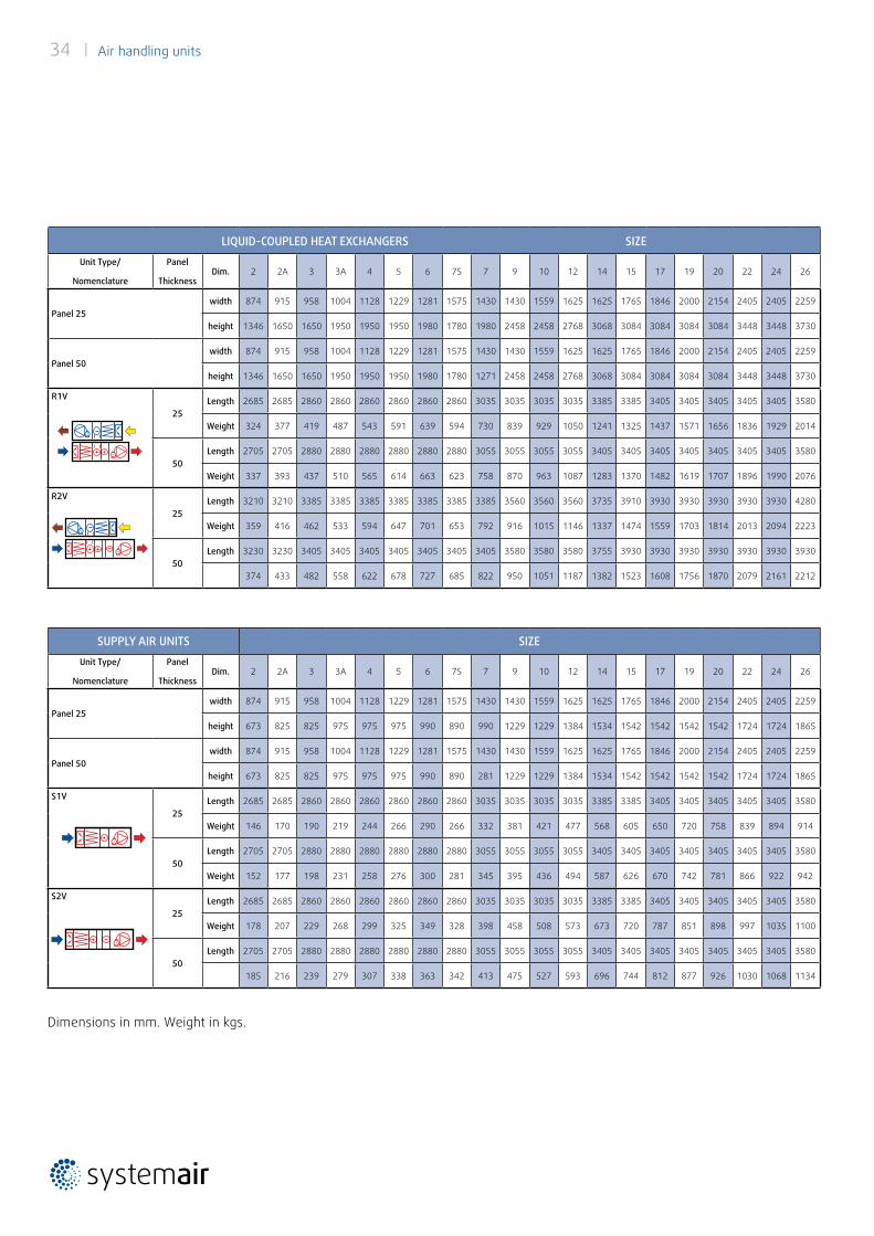
SUPPLY AIR UNITS SIZE
Unit Type/
Nomenclature
Panel
ThicknessDim. 2 2A 3 3A 4 5 6 7S 7 9 10 12 14 15 17 19 20 22 24 26
Panel 25width 874 915 958 1004 1128 1229 1281 1575 1430 1430 1559 1625 1625 1765 1846 2000 2154 2405 2405 2259
height 673 825 825 975 975 975 990 890 990 1229 1229 1384 1534 1542 1542 1542 1542 1724 1724 1865
Panel 50width 874 915 958 1004 1128 1229 1281 1575 1430 1430 1559 1625 1625 1765 1846 2000 2154 2405 2405 2259
height 673 825 825 975 975 975 990 890 281 1229 1229 1384 1534 1542 1542 1542 1542 1724 1724 1865
S1V
25Length 2685 2685 2860 2860 2860 2860 2860 2860 3035 3035 3035 3035 3385 3385 3405 3405 3405 3405 3405 3580
Weight 146 170 190 219 244 266 290 266 332 381 421 477 568 605 650 720 758 839 894 914
50Length 2705 2705 2880 2880 2880 2880 2880 2880 3055 3055 3055 3055 3405 3405 3405 3405 3405 3405 3405 3580
Weight 152 177 198 231 258 276 300 281 345 395 436 494 587 626 670 742 781 866 922 942
S2V
25Length 2685 2685 2860 2860 2860 2860 2860 2860 3035 3035 3035 3035 3385 3385 3405 3405 3405 3405 3405 3580
Weight 178 207 229 268 299 325 349 328 398 458 508 573 673 720 787 851 898 997 1035 1100
50Length 2705 2705 2880 2880 2880 2880 2880 2880 3055 3055 3055 3055 3405 3405 3405 3405 3405 3405 3405 3580
185 216 239 279 307 338 363 342 413 475 527 593 696 744 812 877 926 1030 1068 1134
LIQUID-COUPLED HEAT EXCHANGERS SIZE
Unit Type/
Nomenclature
Panel
ThicknessDim. 2 2A 3 3A 4 5 6 7S 7 9 10 12 14 15 17 19 20 22 24 26
Panel 25width 874 915 958 1004 1128 1229 1281 1575 1430 1430 1559 1625 1625 1765 1846 2000 2154 2405 2405 2259
height 1346 1650 1650 1950 1950 1950 1980 1780 1980 2458 2458 2768 3068 3084 3084 3084 3084 3448 3448 3730
Panel 50width 874 915 958 1004 1128 1229 1281 1575 1430 1430 1559 1625 1625 1765 1846 2000 2154 2405 2405 2259
height 1346 1650 1650 1950 1950 1950 1980 1780 1271 2458 2458 2768 3068 3084 3084 3084 3084 3448 3448 3730
R1V
25Length 2685 2685 2860 2860 2860 2860 2860 2860 3035 3035 3035 3035 3385 3385 3405 3405 3405 3405 3405 3580
Weight 324 377 419 487 543 591 639 594 730 839 929 1050 1241 1325 1437 1571 1656 1836 1929 2014
50Length 2705 2705 2880 2880 2880 2880 2880 2880 3055 3055 3055 3055 3405 3405 3405 3405 3405 3405 3405 3580
Weight 337 393 437 510 565 614 663 623 758 870 963 1087 1283 1370 1482 1619 1707 1896 1990 2076
R2V
25Length 3210 3210 3385 3385 3385 3385 3385 3385 3385 3560 3560 3560 3735 3910 3930 3930 3930 3930 3930 4280
Weight 359 416 462 533 594 647 701 653 792 916 1015 1146 1337 1474 1559 1703 1814 2013 2094 2223
50Length 3230 3230 3405 3405 3405 3405 3405 3405 3405 3580 3580 3580 3755 3930 3930 3930 3930 3930 3930 3930
374 433 482 558 622 678 727 685 822 950 1051 1187 1382 1523 1608 1756 1870 2079 2161 2212
Dimensions in mm. Weight in kgs.
Air handling units | 35
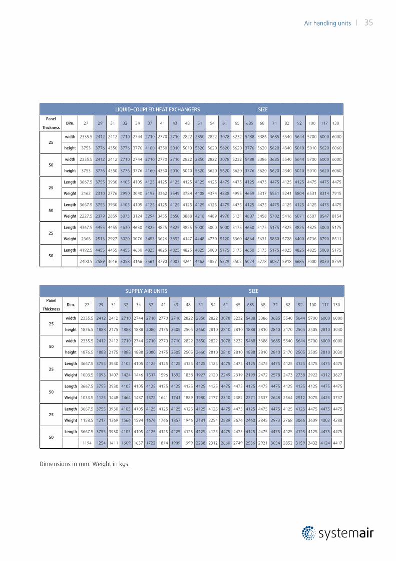
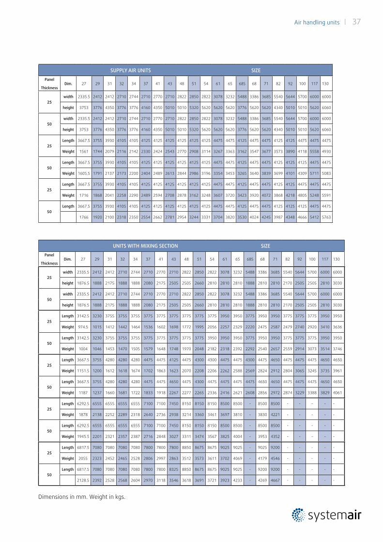
SUPPLY AIR UNITS SIZE
Panel
ThicknessDim. 27 29 31 32 34 37 41 43 48 51 54 61 65 68S 68 71 82 92 100 117 130
25width 2335.5 2412 2412 2710 2744 2710 2770 2710 2822 2850 2822 3078 3232 5488 3386 3685 5540 5644 5700 6000 6000
height 1876.5 1888 2175 1888 1888 2080 2175 2505 2505 2660 2810 2810 2810 1888 2810 2810 2170 2505 2505 2810 3030
50width 2335.5 2412 2412 2710 2744 2710 2770 2710 2822 2850 2822 3078 3232 5488 3386 3685 5540 5644 5700 6000 6000
height 1876.5 1888 2175 1888 1888 2080 2175 2505 2505 2660 2810 2810 2810 1888 2810 2810 2170 2505 2505 2810 3030
25Length 3667.5 3755 3930 4105 4105 4125 4125 4125 4125 4125 4125 4475 4475 4125 4475 4475 4125 4125 4475 4475 4475
Weight 1003.5 1093 1407 1424 1446 1517 1596 1692 1838 1927 2120 2249 2319 2199 2472 2578 2473 2738 2922 4312 3627
50Length 3667.5 3755 3930 4105 4105 4125 4125 4125 4125 4125 4125 4475 4475 4125 4475 4475 4125 4125 4125 4475 4475
Weight 1033.5 1125 1448 1464 1487 1572 1641 1741 1889 1980 2177 2310 2382 2271 2537 2648 2564 2912 3075 4423 3737
25Length 3667.5 3755 3930 4105 4105 4125 4125 4125 4125 4125 4125 4475 4475 4125 4475 4475 4125 4125 4475 4475 4475
Weight 1158.5 1217 1369 1566 1594 1676 1766 1857 1946 2181 2254 2589 2676 2460 2845 2973 2768 3066 3609 4002 4288
50Length 3667.5 3755 3930 4105 4105 4125 4125 4125 4125 4125 4125 4475 4475 4125 4475 4475 4125 4125 4125 4475 4475
1194 1254 1411 1609 1637 1722 1814 1909 1999 2238 2312 2660 2749 2536 2921 3054 2852 3159 3432 4124 4417
LIQUID-COUPLED HEAT EXCHANGERS SIZE
Panel
ThicknessDim. 27 29 31 32 34 37 41 43 48 51 54 61 65 68S 68 71 82 92 100 117 130
25width 2335.5 2412 2412 2710 2744 2710 2770 2710 2822 2850 2822 3078 3232 5488 3386 3685 5540 5644 5700 6000 6000
height 3753 3776 4350 3776 3776 4160 4350 5010 5010 5320 5620 5620 5620 3776 5620 5620 4340 5010 5010 5620 6060
50width 2335.5 2412 2412 2710 2744 2710 2770 2710 2822 2850 2822 3078 3232 5488 3386 3685 5540 5644 5700 6000 6000
height 3753 3776 4350 3776 3776 4160 4350 5010 5010 5320 5620 5620 5620 3776 5620 5620 4340 5010 5010 5620 6060
25Length 3667.5 3755 3930 4105 4105 4125 4125 4125 4125 4125 4125 4475 4475 4125 4475 4475 4125 4125 4475 4475 4475
Weight 2162 2310 2776 2990 3040 3193 3362 3549 3784 4108 4374 4838 4995 4659 5317 5551 5241 5804 6531 8314 7915
50Length 3667.5 3755 3930 4105 4105 4125 4125 4125 4125 4125 4125 4475 4475 4125 4475 4475 4125 4125 4125 4475 4475
Weight 2227.5 2379 2859 3073 3124 3294 3455 3650 3888 4218 4489 4970 5131 4807 5458 5702 5416 6071 6507 8547 8154
25Length 4367.5 4455 4455 4630 4630 4825 4825 4825 4825 5000 5000 5000 5175 4650 5175 5175 4825 4825 4825 5000 5175
Weight 2368 2513 2927 3020 3076 3453 3626 3892 4147 4448 4730 5120 5360 4864 5631 5880 5728 6400 6736 8790 8511
50Length 4192.5 4455 4455 4455 4630 4825 4825 4825 4825 4825 5000 5175 5175 4650 5175 5175 4825 4825 4825 5000 5175
2400.5 2589 3016 3058 3166 3561 3790 4003 4261 4462 4857 5329 5502 5024 5778 6037 5918 6685 7000 9030 8759
Dimensions in mm. Weight in kgs.
36 | Air handling units
UNITS WITH MIXING SECTION SIZE
Unit Type/
Nomenclature
Panel
ThicknessDim. 2 2A 3 3A 4 5 6 7S 7 9 10 12 14 15 17 19 20 22 24 26
Panel 25width 874 915 958 1004 1128 1229 1281 1575 1430 1430 1559 1625 1625 1765 1846 2000 2154 2405 2405 2259
height 673 825 825 975 975 975 990 890 990 1229 1229 1384 1534 1542 1542 1542 1542 1724 1724 1865
Panel 50width 874 915 958 1004 1128 1229 1281 1575 1430 1430 1559 1625 1625 1765 1846 2000 2154 2405 2405 2259
height 673 825 825 975 975 975 990 890 990 1229 1229 1384 1534 1542 1542 1542 1542 1724 1724 1865
M1V
25Length 2160 2160 2335 2335 2335 2335 2335 2335 2510 2510 2510 2510 2860 2860 2880 2880 2880 2880 3055 3055
Weight 148 172 192 224 246 272 292 272 337 384 423 480 571 610 689 727 763 843 915 934
50Length 2180 2180 2355 2355 2355 2355 2355 2355 2530 2355 2530 2530 2880 2880 2880 2880 2880 2880 3055 3055
Weight 154 180 200 233 256 282 303 284 349 380 438 496 591 631 709 748 786 870 943 962
M2V
25Length 2685 2685 2860 2685 2685 2860 2860 2860 3035 3035 2860 3035 3385 3385 3405 3230 3405 3405 3580 3580
Weight 180 213 227 220 244 327 352 332 409 467 490 576 676 785 810 788 903 1001 1078 1103
50Length 2705 2705 2880 2880 2880 3055 2880 2880 3055 2880 3055 3055 3230 3405 3405 3405 3405 3405 3580 3580
Weight 187 222 241 244 269 360 318 299 418 448 526 596 636 810 834 883 931 1034 1112 1137
M3V
25Length 3035 3035 3385 3385 3385 3385 3735 - 3735 3735 4085 4435 4785 4960 5330 5680 5680 5855 6030 6030
Weight 218 246 283 328 366 400 455 - 459 574 657 797 884 1021 1120 1246 1343 1527 1593 1618
50Length 3055 3055 3405 3405 3405 3405 3755 - 3755 4105 4105 4455 5155 4980 5330 5680 5680 5855 6030 6030
Weight 226 256 294 341 381 418 471 - 473 617 680 830 933 1056 1157 1288 1386 1579 1646 1690
M4V
25Length 3560 3560 3910 3735 3735 3910 4260 - 4260 4260 4435 4960 5310 5485 5855 6030 6205 6380 6555 6555
Weight 250 287 318 324 364 455 515 - 531 657 724 893 989 1196 1241 1307 1483 1685 1756 1787
50Length 3580 3580 3930 3930 3930 4105 4280 - 4280 4630 4630 4980 5505 5505 5855 6205 6205 6380 6555 6555
259 298 335 352 394 496 486 - 542 685 768 930 978 1235 1282 1423 1531 1743 1815 1865
SUPPLY AIR UNITS SIZE
Unit Type/
Nomenclature
Panel
ThicknessDim. 2 2A 3 3A 4 5 6 7S 7 9 10 12 14 15 17 19 20 22 24 26
Panel 25width 874 915 958 1004 1128 1229 1281 1575 1430 1430 1559 1625 1625 1765 1846 2000 2154 2405 2405 2259
height 1346 1650 1650 1950 1950 1950 1980 1780 1980 2458 2458 2768 3068 3084 3084 3084 3084 3448 3448 3730
Panel 50width 874 915 958 1004 1128 1229 1281 1575 1430 1430 1559 1625 1625 1765 1846 2000 2154 2405 2405 2259
height 1346 1650 1650 1950 1950 1950 1980 1780 1271 2458 2458 2768 3068 3084 3084 3084 3084 3448 3448 3730
S3V
25Length 2685 2685 2860 2860 2860 2860 2860 2860 3035 3035 3035 3035 3385 3385 3405 3405 3405 3405 3405 3580
Weight 208 237 270 313 347 379 421 372 472 544 607 710 818 893 943 1058 1145 1300 1356 1378
50Length 2705 2705 2880 2880 2880 2880 2880 2880 3055 3055 3055 3055 3405 3405 3405 3405 3405 3405 3405 3580
Weight 216 247 282 329 365 393 437 392 490 564 629 735 855 924 973 1091 1179 1341 1398 1420
S4V
25Length 2685 2685 2860 2860 2860 2860 2860 2860 3035 3035 3035 3035 3385 3385 3405 3405 3405 3405 3405 3580
Weight 240 274 309 362 402 438 480 434 538 621 694 806 923 1008 1080 1189 1285 1458 1497 1564
50Length 2705 2705 2880 2880 2880 2880 2880 2880 3055 3055 3055 3055 3405 3405 3405 3405 3405 3405 3405 3580
249 286 323 377 414 455 500 453 558 644 720 834 964 1042 1115 1226 1324 1505 1544 1612
Dimensions in mm. Weight in kgs.
Air handling units | 37
SUPPLY AIR UNITS SIZE
Panel
ThicknessDim. 27 29 31 32 34 37 41 43 48 51 54 61 65 68S 68 71 82 92 100 117 130
25width 2335.5 2412 2412 2710 2744 2710 2770 2710 2822 2850 2822 3078 3232 5488 3386 3685 5540 5644 5700 6000 6000
height 3753 3776 4350 3776 3776 4160 4350 5010 5010 5320 5620 5620 5620 3776 5620 5620 4340 5010 5010 5620 6060
50width 2335.5 2412 2412 2710 2744 2710 2770 2710 2822 2850 2822 3078 3232 5488 3386 3685 5540 5644 5700 6000 6000
height 3753 3776 4350 3776 3776 4160 4350 5010 5010 5320 5620 5620 5620 3776 5620 5620 4340 5010 5010 5620 6060
25Length 3667.5 3755 3930 4105 4105 4125 4125 4125 4125 4125 4125 4475 4475 4125 4475 4475 4125 4125 4475 4475 4475
Weight 1561 1744 2079 2116 2142 2330 2424 2543 2770 2908 3114 3267 3363 3162 3547 3677 3573 3890 4118 5558 4930
50Length 3667.5 3755 3930 4105 4105 4125 4125 4125 4125 4125 4125 4475 4475 4125 4475 4475 4125 4125 4125 4475 4475
Weight 1605.5 1791 2137 2173 2200 2404 2489 2613 2844 2986 3196 3354 3453 3265 3640 3839 3699 4101 4309 5711 5083
25Length 3667.5 3755 3930 4105 4105 4125 4125 4125 4125 4125 4125 4475 4475 4125 4475 4475 4125 4125 4475 4475 4475
Weight 1716 1868 2041 2258 2290 2489 2594 2708 2878 3162 3248 3607 3720 3423 3920 4072 3868 4218 4805 5248 5591
50Length 3667.5 3755 3930 4105 4105 4125 4125 4125 4125 4125 4125 4475 4475 4125 4475 4475 4125 4125 4125 4475 4475
1766 1920 2100 2318 2350 2554 2662 2781 2954 3244 3331 3704 3820 3530 4024 4245 3987 4348 4666 5412 5763
UNITS WITH MIXING SECTION SIZE
Panel
ThicknessDim. 27 29 31 32 34 37 41 43 48 51 54 61 65 68S 68 71 82 92 100 117 130
25width 2335.5 2412 2412 2710 2744 2710 2770 2710 2822 2850 2822 3078 3232 5488 3386 3685 5540 5644 5700 6000 6000
height 1876.5 1888 2175 1888 1888 2080 2175 2505 2505 2660 2810 2810 2810 1888 2810 2810 2170 2505 2505 2810 3030
50width 2335.5 2412 2412 2710 2744 2710 2770 2710 2822 2850 2822 3078 3232 5488 3386 3685 5540 5644 5700 6000 6000
height 1876.5 1888 2175 1888 1888 2080 2175 2505 2505 2660 2810 2810 2810 1888 2810 2810 2170 2505 2505 2810 3030
25Length 3142.5 3230 3755 3755 3755 3775 3775 3775 3775 3775 3775 3950 3950 3775 3950 3950 3775 3775 3775 3950 3950
Weight 974.5 1015 1412 1442 1464 1536 1602 1698 1772 1995 2056 2257 2329 2220 2475 2587 2479 2740 2920 3410 3636
50Length 3142.5 3230 3755 3755 3755 3775 3775 3775 3775 3775 3950 3950 3950 3775 3950 3950 3775 3775 3775 3950 3950
Weight 1004 1046 1453 1470 1505 1579 1648 1748 1970 2048 2182 2318 2392 2292 2540 2657 2559 2914 3073 3514 3746
25Length 3667.5 3755 4280 4280 4280 4475 4475 4125 4475 4300 4300 4475 4475 4300 4475 4650 4475 4475 4475 4650 4650
Weight 1151.5 1200 1612 1618 1674 1702 1863 1623 2070 2208 2206 2262 2588 2569 2824 2912 2804 3065 3245 3735 3961
50Length 3667.5 3755 4280 4280 4280 4475 4475 4650 4475 4300 4475 4475 4475 4475 4650 4650 4475 4475 4475 4650 4650
Weight 1187 1237 1660 1681 1722 1833 1918 2267 2277 2265 2336 2416 2621 2608 2856 2972 2874 3229 3388 3829 4061
25Length 6292.5 6555 6555 6555 6555 7100 7100 7450 8150 8150 8150 8500 8500 - 8500 8500 - - - - -
Weight 1878 2138 2252 2289 2318 2640 2736 2938 3214 3360 3461 3697 3810 - 3830 4221 - - - - -
50Length 6292.5 6555 6555 6555 6555 7100 7100 7450 8150 8150 8150 8500 8500 - 8500 8500 - - - - -
Weight 1945.5 2201 2321 2357 2387 2716 2848 3027 3311 3474 3567 3825 4004 - 3953 4352 - - - - -
25Length 6817.5 7080 7080 7080 7080 7800 7800 7800 8850 8675 8675 9025 9025 - 9025 9200 - - - - -
Weight 2055 2323 2452 2465 2528 2806 2997 2863 3512 3573 3611 3702 4069 - 4179 4546 - - - - -
50Length 6817.5 7080 7080 7080 7080 7800 7800 8325 8850 8675 8675 9025 9025 - 9200 9200 - - - - -
2128.5 2392 2528 2568 2604 2970 3118 3546 3618 3691 3721 3923 4233 - 4269 4667 - - - - -
Dimensions in mm. Weight in kgs.
38 | Air handling units
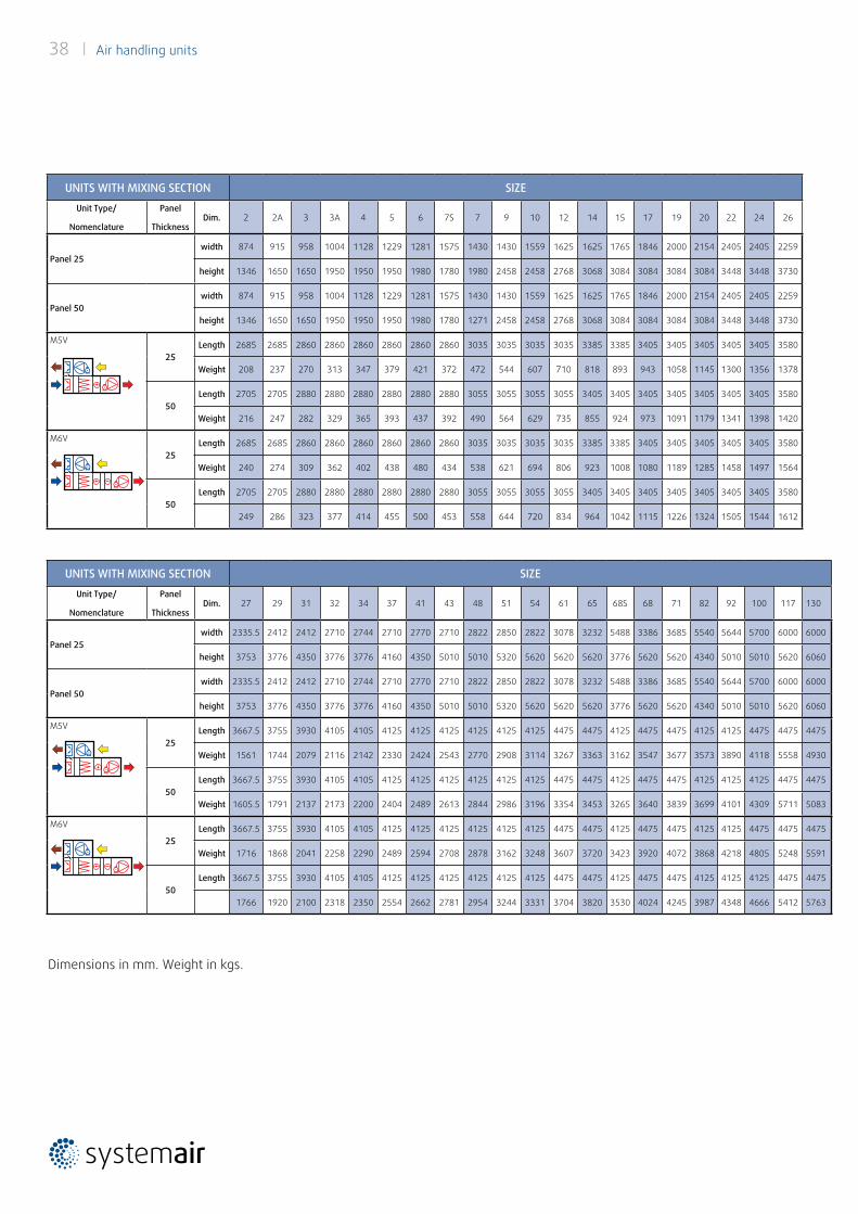
UNITS WITH MIXING SECTION SIZE
Unit Type/
Nomenclature
Panel
ThicknessDim. 27 29 31 32 34 37 41 43 48 51 54 61 65 68S 68 71 82 92 100 117 130
Panel 25width 2335.5 2412 2412 2710 2744 2710 2770 2710 2822 2850 2822 3078 3232 5488 3386 3685 5540 5644 5700 6000 6000
height 3753 3776 4350 3776 3776 4160 4350 5010 5010 5320 5620 5620 5620 3776 5620 5620 4340 5010 5010 5620 6060
Panel 50width 2335.5 2412 2412 2710 2744 2710 2770 2710 2822 2850 2822 3078 3232 5488 3386 3685 5540 5644 5700 6000 6000
height 3753 3776 4350 3776 3776 4160 4350 5010 5010 5320 5620 5620 5620 3776 5620 5620 4340 5010 5010 5620 6060
M5V
25Length 3667.5 3755 3930 4105 4105 4125 4125 4125 4125 4125 4125 4475 4475 4125 4475 4475 4125 4125 4475 4475 4475
Weight 1561 1744 2079 2116 2142 2330 2424 2543 2770 2908 3114 3267 3363 3162 3547 3677 3573 3890 4118 5558 4930
50Length 3667.5 3755 3930 4105 4105 4125 4125 4125 4125 4125 4125 4475 4475 4125 4475 4475 4125 4125 4125 4475 4475
Weight 1605.5 1791 2137 2173 2200 2404 2489 2613 2844 2986 3196 3354 3453 3265 3640 3839 3699 4101 4309 5711 5083
M6V
25Length 3667.5 3755 3930 4105 4105 4125 4125 4125 4125 4125 4125 4475 4475 4125 4475 4475 4125 4125 4475 4475 4475
Weight 1716 1868 2041 2258 2290 2489 2594 2708 2878 3162 3248 3607 3720 3423 3920 4072 3868 4218 4805 5248 5591
50Length 3667.5 3755 3930 4105 4105 4125 4125 4125 4125 4125 4125 4475 4475 4125 4475 4475 4125 4125 4125 4475 4475
1766 1920 2100 2318 2350 2554 2662 2781 2954 3244 3331 3704 3820 3530 4024 4245 3987 4348 4666 5412 5763
UNITS WITH MIXING SECTION SIZE
Unit Type/
Nomenclature
Panel
ThicknessDim. 2 2A 3 3A 4 5 6 7S 7 9 10 12 14 15 17 19 20 22 24 26
Panel 25width 874 915 958 1004 1128 1229 1281 1575 1430 1430 1559 1625 1625 1765 1846 2000 2154 2405 2405 2259
height 1346 1650 1650 1950 1950 1950 1980 1780 1980 2458 2458 2768 3068 3084 3084 3084 3084 3448 3448 3730
Panel 50width 874 915 958 1004 1128 1229 1281 1575 1430 1430 1559 1625 1625 1765 1846 2000 2154 2405 2405 2259
height 1346 1650 1650 1950 1950 1950 1980 1780 1271 2458 2458 2768 3068 3084 3084 3084 3084 3448 3448 3730
M5V
25Length 2685 2685 2860 2860 2860 2860 2860 2860 3035 3035 3035 3035 3385 3385 3405 3405 3405 3405 3405 3580
Weight 208 237 270 313 347 379 421 372 472 544 607 710 818 893 943 1058 1145 1300 1356 1378
50Length 2705 2705 2880 2880 2880 2880 2880 2880 3055 3055 3055 3055 3405 3405 3405 3405 3405 3405 3405 3580
Weight 216 247 282 329 365 393 437 392 490 564 629 735 855 924 973 1091 1179 1341 1398 1420
M6V
25Length 2685 2685 2860 2860 2860 2860 2860 2860 3035 3035 3035 3035 3385 3385 3405 3405 3405 3405 3405 3580
Weight 240 274 309 362 402 438 480 434 538 621 694 806 923 1008 1080 1189 1285 1458 1497 1564
50Length 2705 2705 2880 2880 2880 2880 2880 2880 3055 3055 3055 3055 3405 3405 3405 3405 3405 3405 3405 3580
249 286 323 377 414 455 500 453 558 644 720 834 964 1042 1115 1226 1324 1505 1544 1612
Dimensions in mm. Weight in kgs.
Air handling units | 39
40 | Air handling units
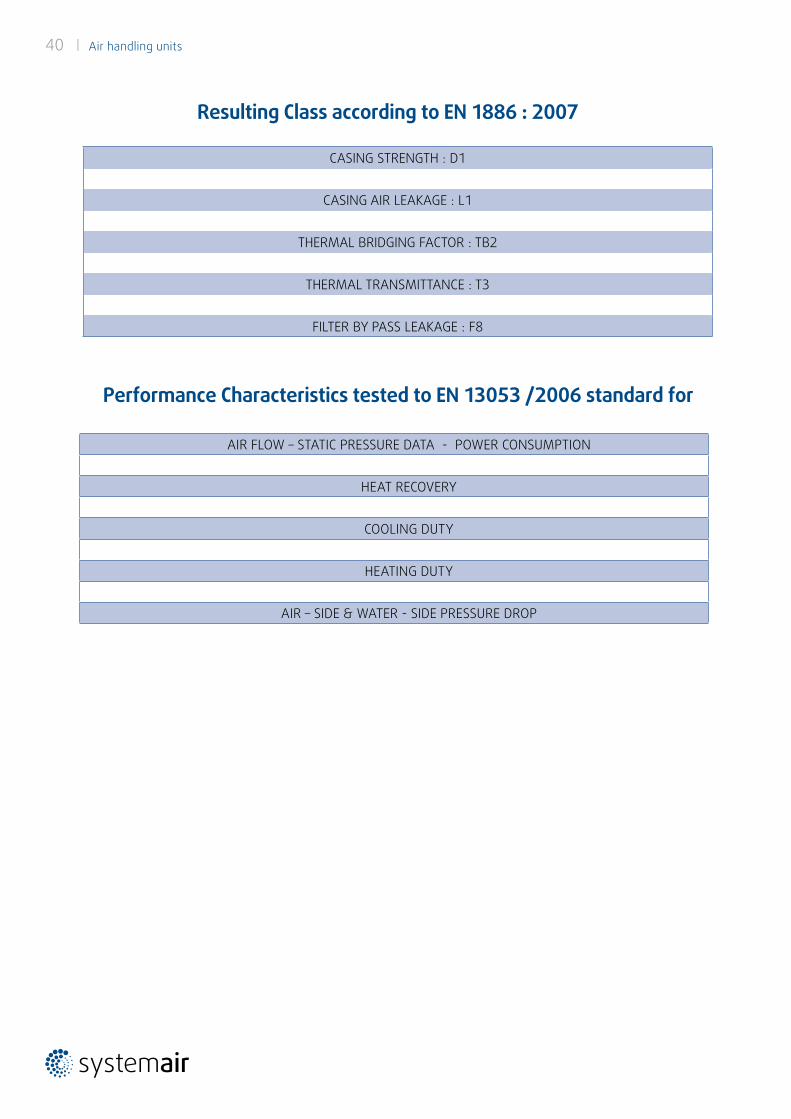
CASING STRENGTH : D1
CASING AIR LEAKAGE : L1
THERMAL BRIDGING FACTOR : TB2
THERMAL TRANSMITTANCE : T3
FILTER BY PASS LEAKAGE : F8
Resulting Class according to EN 1886 : 2007
Performance Characteristics tested to EN 13053 /2006 standard for
AIR FLOW – STATIC PRESSURE DATA - POWER CONSUMPTION
HEAT RECOVERY
COOLING DUTY
HEATING DUTY
AIR – SIDE & WATER - SIDE PRESSURE DROP
Air handling units | 41
EUROVENT CERTITA CERTIFICATION SAS au capital de 100 000 € - 48-50 rue de la Victoire 75009 Paris - FRANCE Tel. : 33 (0)1 75 44 71 71 - 513 133 637 RCS Paris - SIRET 513 133 637 000 35 - TVA FR 59513133637
S06 D06 TEMPLATE_ECP_RANGE_REV1.0
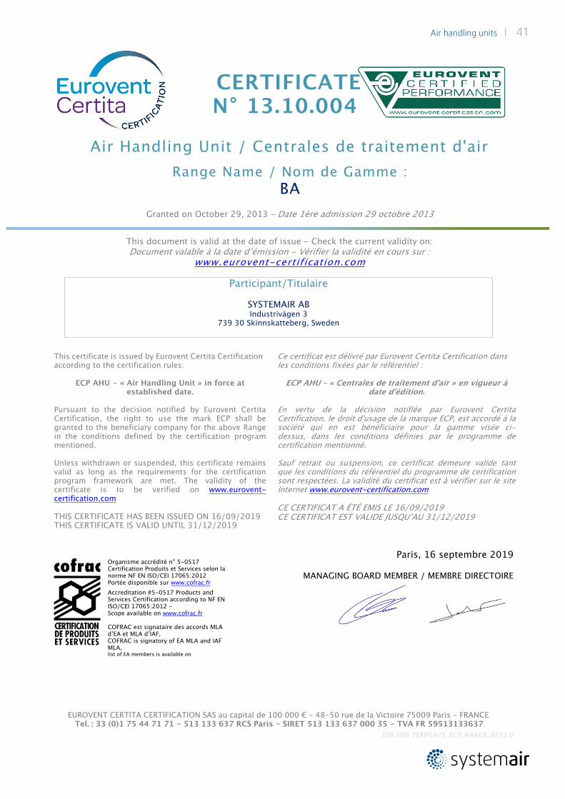
CERTIFICATE N° 13.10.004
Air Handling Unit / Centrales de traitement d'airRange Name / Nom de Gamme :
BAGranted on October 29, 2013 - Date 1ère admission 29 octobre 2013
This document is valid at the date of issue - Check the current validity on: Document valable à la date d’émission - Vérifier la validité en cours sur :
www.eurovent-certification.comParticipant/Titulaire
SYSTEMAIR ABIndustrivägen 3
739 30 Skinnskatteberg, Sweden
This certificate is issued by Eurovent Certita Certification according to the certification rules:
ECP AHU - « Air Handling Unit » in force at established date.
Pursuant to the decision notified by Eurovent Certita Certification, the right to use the mark ECP shall be granted to the beneficiary company for the above Range in the conditions defined by the certification program mentioned.Unless withdrawn or suspended, this certificate remains valid as long as the requirements for the certification program framework are met. The validity of the certificate is to be verified on www.eurovent-certification.comTHIS CERTIFICATE HAS BEEN ISSUED ON 16/09/2019 THIS CERTIFICATE IS VALID UNTIL 31/12/2019
Ce certificat est délivré par Eurovent Certita Certification dans les conditions fixées par le référentiel :
ECP AHU – « Centrales de traitement d'air » en vigueur à date d’édition.
En vertu de la décision notifiée par Eurovent Certita Certification, le droit d'usage de la marque ECP, est accordé à la société qui en est bénéficiaire pour la gamme visée ci-dessus, dans les conditions définies par le programme de certification mentionné.Sauf retrait ou suspension, ce certificat demeure valide tant que les conditions du référentiel du programme de certification sont respectées. La validité du certificat est à vérifier sur le site Internet www.eurovent-certification.comCE CERTIFICAT A ÉTÉ EMIS LE 16/09/2019CE CERTIFICAT EST VALIDE JUSQU’AU 31/12/2019
Paris, 16 septembre 2019 MANAGING BOARD MEMBER / MEMBRE DIRECTOIRE
Organisme accrédité n° 5-0517 Certification Produits et Services selon la norme NF EN ISO/CEI 17065:2012 Portée disponible sur www.cofrac.frAccreditation #5-0517 Products and Services Certification according to NF EN ISO/CEI 17065:2012 –Scope available on www.cofrac.frCOFRAC est signataire des accords MLA d’EA et MLA d’IAF, COFRAC is signatory of EA MLA and IAF MLA, list of EA members is available on
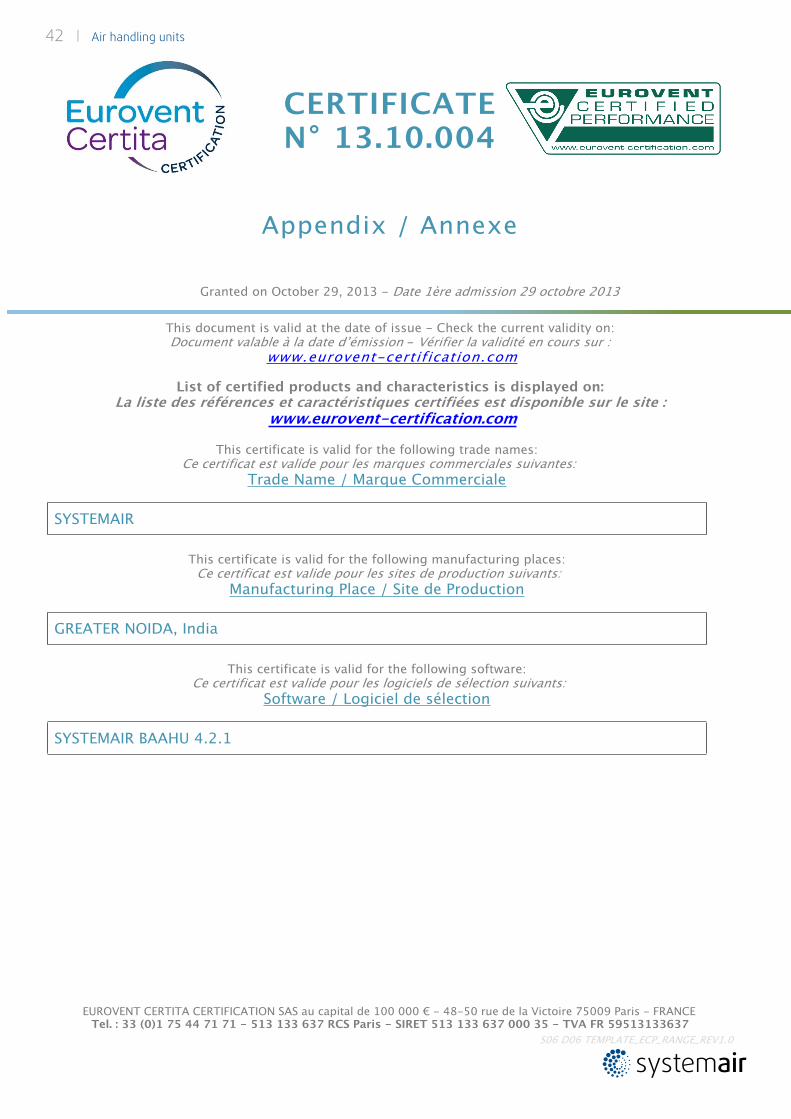
CERTIFICATE N° 13.10.004
Appendix / Annexe
Granted on October 29, 2013 - Date 1ère admission 29 octobre 2013
This document is valid at the date of issue - Check the current validity on:Document valable à la date d’émission - Vérifier la validité en cours sur :
www.eurovent-certification.comList of certified products and characteristics is displayed on:
La liste des références et caractéristiques certifiées est disponible sur le site : www.eurovent-certification.com
EUROVENT CERTITA CERTIFICATION SAS au capital de 100 000 € - 48-50 rue de la Victoire 75009 Paris - FRANCE Tel. : 33 (0)1 75 44 71 71 - 513 133 637 RCS Paris - SIRET 513 133 637 000 35 - TVA FR 59513133637
S06 D06 TEMPLATE_ECP_RANGE_REV1.0
This certificate is valid for the following trade names: Ce certificat est valide pour les marques commerciales suivantes:
Trade Name / Marque Commerciale
SYSTEMAIR
This certificate is valid for the following manufacturing places: Ce certificat est valide pour les sites de production suivants:
Manufacturing Place / Site de Production
GREATER NOIDA, India
This certificate is valid for the following software: Ce certificat est valide pour les logiciels de sélection suivants:
Software / Logiciel de sélection
SYSTEMAIR BAAHU 4.2.1
42 | Air handling units
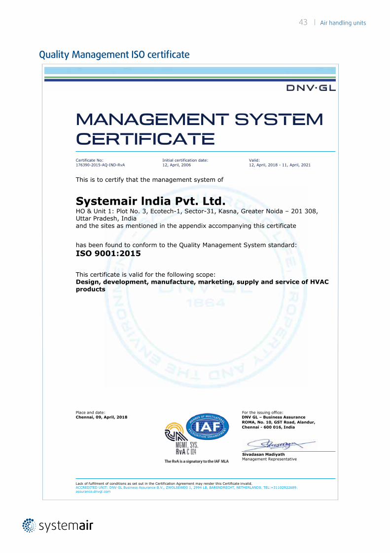
43 | Air handling units
Quality Management ISO certificate
MANAGEMENT SYSTEM CERTIFICATE Certificate No:176390-2015-AQ-IND-RvA
Initial certification date: 12, April, 2006
Valid:12, April, 2018 - 11, April, 2021
This is to certify that the management system of
Systemair lndia Pvt. Ltd.HO & Unit 1: Plot No. 3, Ecotech-1, Sector-31, Kasna, Greater Noida – 201 308, Uttar Pradesh, Indiaand the sites as mentioned in the appendix accompanying this certificate
has been found to conform to the Quality Management System standard:ISO 9001:2015
This certificate is valid for the following scope:Design, development, manufacture, marketing, supply and service of HVAC products
Place and date: For the issuing office:Chennai, 09, April, 2018 DNV GL – Business Assurance
ROMA, No. 10, GST Road, Alandur, Chennai - 600 016, India
Sivadasan MadiyathManagement Representative
Lack of fulfilment of conditions as set out in the Certification Agreement may render this Certificate invalid.ACCREDITED UNIT: DNV GL Business Assurance B.V., ZWOLSEWEG 1, 2994 LB, BARENDRECHT, NETHERLANDS. TEL:+31102922689.assurance.dnvgl.com
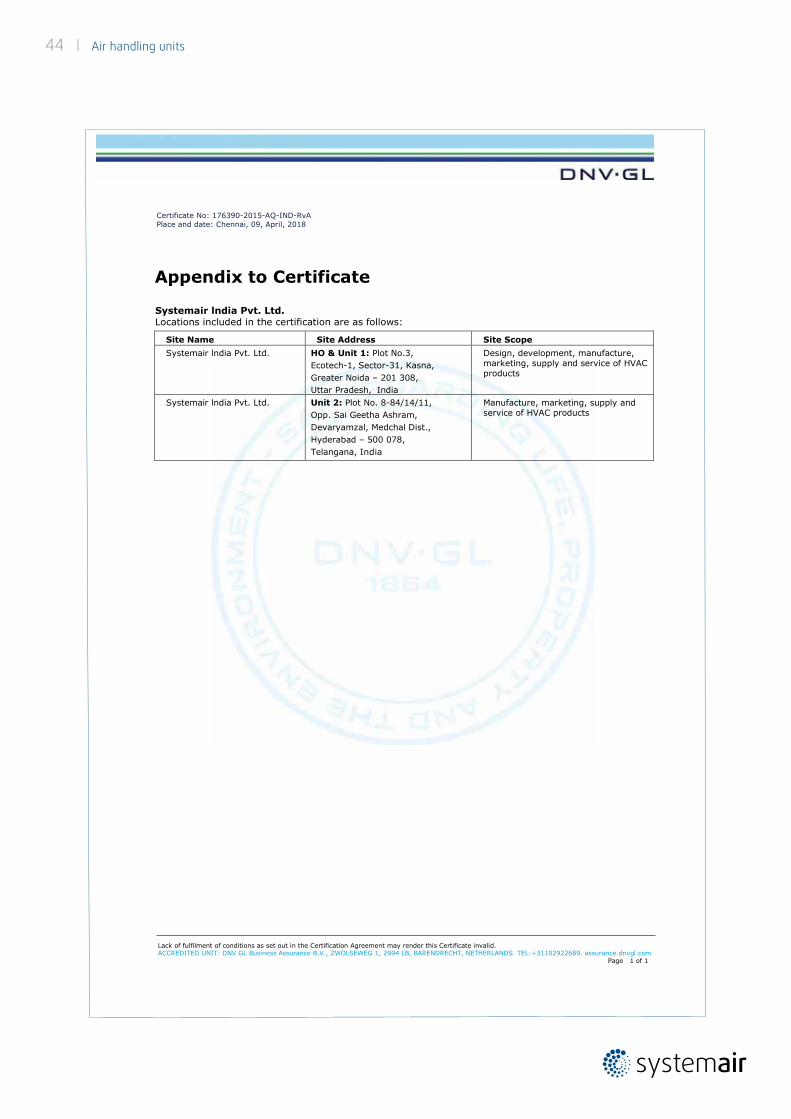
Certificate No: 176390-2015-AQ-IND-RvA Place and date: Chennai, 09, April, 2018
Appendix to Certificate
Systemair lndia Pvt. Ltd.Locations included in the certification are as follows:
Site Name Site Address Site ScopeSystemair lndia Pvt. Ltd. HO & Unit 1: Plot No.3,
Ecotech-1, Sector-31, Kasna, Greater Noida – 201 308, Uttar Pradesh, India
Design, development, manufacture, marketing, supply and service of HVAC products
Systemair lndia Pvt. Ltd. Unit 2: Plot No. 8-84/14/11,Opp. Sai Geetha Ashram,Devaryamzal, Medchal Dist.,Hyderabad – 500 078,Telangana, India
Manufacture, marketing, supply and service of HVAC products
Lack of fulfilment of conditions as set out in the Certification Agreement may render this Certificate invalid.ACCREDITED UNIT: DNV GL Business Assurance B.V., ZWOLSEWEG 1, 2994 LB, BARENDRECHT, NETHERLANDS. TEL:+31102922689. assurance.dnvgl.com
Page 1 of 1
44 | Air handling units
Few of our valued customersPharmaceuticals / Clean Room
1 ACG-Pithampur2 ACME Formulation-Baddi3 Actoverco-Iran4 Agila Specialities Pvt. Ltd.5 Ahlcon Parenterals India Ltd.6 Akorn India Pvt. Ltd.7 Aleor Dermaceuticals Ltd.8 Alkem Laboratories, Baddi9 Alpha Pharma Healthcare (I) Pvt. Ltd.-Thane
10 Apotex11 Ashrae Clean Room, Hy’bad12 Atra Pharmaceuticals13 Avantis Pharma14 BCG Vaccine Laboratories-Tamilnadu15 Bengal Chemical, Kolkata16 Biocon Pharma17 Biocon SDN BHD-Malaysia18 Biological E Limited-Hyderabad19 BSL / German Remedies Ltd., Goa20 Cipla Limited-Bengaluru/Pune/Sikkim21 Cosmo Laboratories, Ludhiana22 Dhanuka Laboratories Ltd.23 Dr. Actoverco-Iran24 Dr. Reddy’s Laboratories25 East African (India) Overseas26 E-Biological, Pune27 EISAI Pharmaceuticals India Pvt. Ltd.-Vizag28 Elysium Pharmaceuticals Limited29 Emami Limited- Dongari/ Vapi 30 Emami Research Park31 Fresenius Kabi Oncology Ltd.32 Goa Formulation Ltd.33 Gufic-Ahmedabad34 HBL Limited-Tamilnadu35 Hellios Pharma, Baddi 36 Hindustan Liver Limited37 Hospira, Vishakhapatnam38 HPL Pharmaceutical, Bangladesh39 Immacule-Nalagarh40 Innova Captab, Baddi41 INTAS Pharmaceuticals, Ahmedabad
42 IPCA Laboratories Ltd.43 Jodas Expoim Pvt. Ltd.-Hyderabad44 Johnsons & Johnsons Ltd.45 Life Pharma-Dubai46 Mankind Pharma Limited47 Marck Parentrals 48 Martin &Harris Labs Ltd.49 Mayer Organics Pvt. Ltd., 50 Medical Cyclotron Centre-Kolkata51 MICO, B’lore 52 Morepan Lab. Baddi 53 Mylan Laboratories54 Nabros Pharma Pvt. Ltd.55 Neon Pharma56 Nicolas Piramal, Mumbai57 Okasa Remedies Daman58 Optimus Pharma-Hyderabad59 Pan Pharma, Baroda60 Parsan Oversease (P) Limited61 Perrigo API India Pvt. Ltd.62 Pfizer, Mumbai63 Project at Myanmar64 Ranbaxy Laboratory-Dewas,Toansa,Baddi,
Mohali, Poanta Sahib65 Sangre-La Pharma66 Scott Edil Adv. Reseach Lab & Education Ltd.67 Sekh Saria Chemicals68 Sequent Pharma69 Serum Institute-Pune70 Shree Ji Laboratory Pvt. Ltd.71 Sidmak Laboratories (I) Pvt.Ltd.72 Stelis Biopharma-Bangalore73 Sudair Pharma74 Sun Pharma Sikkim-II & Dadra75 Sunpharma-Basaka76 Swiss Garnier Genexiaa Sciences-Sikkim77 Syngene International Ltd.78 Teva-Gajraula, Malanpur79 Torrent Pharmaceuticals Ltd., Dahej, Baddi,
Ahmedabad, Indrad
Air handling units | 45
80 Troikaa Pharmaceuticals Ltd.81 Unichem Laboratories-Pithampur, Roha82 USV Ltd., Baddi, Mumbai, Daman83 Vitane-Iran84 Watson Pharma Limited85 West Pharma86 Wockhardt Ltd.
Industrial
1 Amway India Enterprises Pvt. Ltd.2 Apollo Tyres3 Asian Paints Ltd., Mumbai4 BARC-Mysore5 BHEL, Bhopal6 Bosch Ltd.7 British High Commission8 CGPL, Mundra9 Colgate, Baddi
10 ETA/Warner Lambert 11 Exxon Co./ Voltas Ltd., Bangalore12 Godrej Hospital, Mumbai13 HB Estate, Gurgaon14 IEML, NOIDA15 IGIB, NewDelhi16 IOCL, Barauni ,Bihar17 IOCL, Faridabad18 IOCL, Medinipur, WB19 JMI, New Delhi20 JRRCRL-Jaipur21 Mars International India Pvt. Ltd.22 MES-Manesar, Jabalpur, Shimla23 NABARD, Lucknow 24 NCBS, Bangalore25 Oberoi Airport Services, New Delhi26 Om Kar Builder27 Paradip Refinery IOCL28 Price Water House, Calcutta29 Procter & Gamble, Singapore30 Punj Lloyd Ltd., Gurgaon 31 Rajwest Power Plant
32 SAIL IISCO-Burnpur33 SBC, Hyderabad34 Scott Edil Advance Research Lab & Edu. Ltd.35 Sekhsaria Chemicals36 Serum Institute, Pune37 Texas Instrument, B’lore38 Thermax Solar Power Plant, Jaisalmer39 Tmcb-2 Bombay Dyeing40 Unitech Hi-Tech Structures Limited.-Kolkata41 Vacmet India Ltd.42 Warner Lambert
Hospital
1 AIIMS, New Delhi 2 Alexis Hospital-Nagpur3 Apollo Hospital4 Apollo Reach Hospital-Trichy5 Cancer Hospital-Bathinda6 Centre for Digestive & Kidney Disease, Mumbai
7 Dhanalakshmi Srinivasan Medical College & Hospital
8 Dr. L.H. Hiranandani Hospital, 9 EPR Centre (Vitane)
10 Escorts Heart Institute11 ESIC Hospitals
12Eternal Healthcare Centre & Research Insti-tute Pvt. Ltd., Jaipur
13 Fortis Hospital, New Delhi14 Godrej Hospital-Mumbai15 Hiranandani Hospital-Mumbai16 Jaypee Medical Center17 Krishna Heart Institute, Amedabad18 Manipal Medical Institute, Nepal19 Mata Chanan Devi Hospital 20 Max Hospital, Shalimar Bagh, New Delhi21 Sanjay Gandhi Hospital, New Delhi 22 Shillong Hospital23 Sir Ganga Ram Hospital, New Delhi24 Tata Memorial Cancer Hospital-Vizag25 Trauma Center, New Delhi26 Udgir Hospital27 West Bengal Hospital
46 | Air handling units
Commercial Office
1 Amanora Park Town-Pune2 American Embassy School, New Delhi3 Amity-Noida4 Anjaneya Building-Bangalore5 Ansal Plaza Mall, Ghaziabad 6 British High Commission7 BSL/Eagelton –The Golf Village, Bangalore8 BSNL, New Delhi 9 Callnet India Pvt. Ltd.
10 Cargo Complex, New Delhi11 Cyber Park, Gurgaon12 Cyber Walk, Manesar13 Daksh Call Centre, Gurgaon 14 DHL Airfreight, Gurgaon15 Era Infra Engineering Limited16 Global Business Park, Gurgaon17 Godrej IT Park, Mumbai18 Golden Heights, Bangalore19 IIL, Hyderabad20 IIT, Kanpur21 IIT-Mumbai22 Inorbit Mall-Pune, Malad, Mumbai, Vasi23 I-Park, Gurgaon (Amendment)24 ISRO, Lucknow 25 Jaipur Central Developers P. Ltd.26 Jaipur Stock Exchange27 Jindal Saw, Gurgaon28 JMI-New Delhi29 Khalsa Heritage, Punjab30 LIC Mumbai31 LMT School of Management, Punjab32 Lodha I Think-Mumbai33 Manjeera Mall34 Market City, Kurla35 Mind Space Club, Mumbai36 Mind Space, Hyderabad 38 Motherson Corporate Office, Noida39 MTNL Mumbai40 New District Court-Chandigarh41 Orchid Agora, Gurgaon 42 Orchid Square, Gurgaon 43 Parinee, Mumbai
Hotels
1 Aakriti Hotel, Greater Noida2 Bharat Hotel Limited, Jaipur3 Botanix Resorts-Gurgaon4 Dusit Devrana Hotel, New Delhi-I5 Fortune Hotel, Gurgaon 6 Ganapath Hotel-Mysore7 Garden-Galeria8 Goa Hotels (Hyatt Goa) HRW9 Grand Hyatt, Goa
10 Grand Hyatt-Cochin11 Hotel Hyatt Regency, Calcutta12 Hotel Intercontinental-Dhaka13 Hotel Kaniska, New Delhi 14 Hotel Marriott, New Delhi15 Hotel Shang RE-LA16 Hotel Udaivilas, Udaipur17 Hotel Yak & Yeti, Nepal18 Hyatt Andaz-New Delhi19 IBIS hotel, New Delhi20 ITC Gardenia-Bangalore21 ITC Green Bharat22 ITC Ltd., Gurgaon 23 Jas Hotel at Amritsar24 JW Marriot25 KBJ Grand-Varanasi26 Kenwood Hotel, Mumbai27 Lemon Tree Hotel, Hyderabad28 Malsi Hotel, Dehradun29 MBD Hotels, Jalandhar30 Novotel Hotel, Gurgaon31 Piccadily Hotels Pvt. Ltd.32 Powai Plaza, Mumbai 33 Radisson Hotel-Guwahati34 Raj Chopra Mussoorie Hotel35 Royal Orchid Hotel at Jaipur36 Sheraton Hotel-Gr. Noida, New Delhi, Jaipur37 Taj-Bangalore, Kolkata, Mumbai, Hyderabad38 The Oberoi39 Tip Top Hotel-Pune40 Today Hotel 41 Waves Hospitality Pvt. Ltd.42 Westin Hotel-Gurgaon
Air handling units | 47
44 Park View Business Tower45 Parliament Library, New Delhi46 Pothys Textiles, Chennai47 Power Finance Corporation48 Prasar Bharti, New Delhi 49 PSP Projects Pvt. Ltd.-Gandhinagar50 Punj Lloyd-Gurgaon51 Raheja Building, 1A52 RITES Ltd., Gurgaon 53 Ritnand Balved Education Foundation,
Lucknow54 Seawoods-Navi Mumbai55 Shopat Mantri, Bengaluru56 Shri Guru Ram Das Institute of Dental Sci-
ence & Research57 SRMT Mall-Kakinada58 Star TV India-Mumbai59 Thimphu Tech Park, Bhutan60 TOD-Hyderabad61 TG Arla Dairy Products Lftz Enterprises-
Nigeria62 Unitech Business Park, Gurgaon 63 Vatika-Tech Park, City, Hospitality64 Vipul Business Park-Gurgaon65 Voltas / TCS Salt Lake, Calcutta66 WHO, Delhi 67 Windsor, Mumbai 68 YKK India
Infrastructure
1 Bangabandhu military museum, Bangladesh2 Cochin International Airport Ltd.3 Delhi Metro Rail Corporation4 Shivaji Stadium, New Delhi5 TN Assembly Building6 Rashtrapati Bhawan7 DU Commom Wealth Games8 Airport Authority of India9 IAAI Guwahati Airport, Calcutta
10 ULCC Infrastructure (P) Ltd.11 Hyderabad International Airport12 Delhi International Airport
IT / ITES
1 Accenture Services, Bengaluru2 ARN IT Park, Greater Noida3 CIS Udyog Vihar, Gurgaon4 Cognizant Technology Service, Chennai5 Computer Associates, B’lore
6 E-Serve International, Mumbai7 Hughes Software, Gurgaon 8 I Gate-Pune9 Infosys Ltd., Bengaluru, Mangalore, Pune,
Trivenderum10 IT Square, Greater Noida11 Net Apps-Bangalore12 Oxygen at Noida13 Phillips Software, Bangalore 14 Phoenix Infocity Pv.t Ltd.15 Pune Embassy Projects Pvt. Ltd.,16 S.P. Infocity, Manesar17 Tata Teleservices, New Delhi 18 TCS Salt Lake-Calcutta19 TCS, Bangalore 20 Tidel Park, Chennai21 Wipro Limited
Technical Assistance & Customer Care Services
Systemair India provides to all customers a Technical Assistance Service by highly qualified and exprienced team having specialization in both Industrial and comfort facilities. We also offer a service for commissioning and technical advice for the equipment supplied to our valued customers. Kindly feel free to contact us or request a quote for such services.
www.systemair.in
Tel. +91 (0120) 476 3100 / 3140
48 | Air handling units
48 | Air handling units
Syst
emai
r IN
/ A
HU
/ 09
/ 20
18
www.systemair.in
SYSTEMAIR INDIA (Head office & Manufacturing Plant India)
LEED Platinum campusPlot No.03, ECOTECH I, Sector-31, Kasna, Greater Noida, U.P - 201308.Tel: +91 120 4763 100 Fax: +91 120 4763 101
NORTH & EXPORT
NoidaA-19, First Floor, Sector-64 Noida, U.P 201307Tel: +91 120 4639 700
EAST
Kolkata92/2A Bidhan Nagar Road, Kolkata, West Bengal -700067 Tel: +91 983 0420 473
WEST
MumbaiOffice No. G 16, Neo Corporate Plaza, RamChandra Lane Ext., Kanchpada, Malad West, Mumbai-400064Tel: +91 08108124863
PuneOffice No 7B , B wing Manorama Apartments Lane no 7, Prabhat Road, Pune-411004 Tel: +91 9823987810
Ahmedabad138/1655, Karnavati Appartment, Paras Nagar, Sola Road, Naranpura, Ahmedabad-380063 Tel: +91 9624 448 912 / 9823987810
SOUTH
HyderabadPlot No. 8-84/14/11; Opp. Sai Geetha Ashram; Devaryamzal, Medchal Dist, Hyderabad 500078Tel:+91 40 40176398 / 9686454434
Bengaluru40 Sindhoora, MLA Layout, Block 4, RMV 2nd Stage,Bengaluru, Karnataka - 560094 Tel: +91 80 2341 6922 / 9686454434
Cochin53/1690 B, 2nd Floor. Meppullil Building, Vyttila Ernakulam , Kerala -682019 Tel: +91 904 8181 300 / 9686454434
ChennaiTel: +91 9686454434