Failure codes fendt 900 Vario 09 2007
201
description
Failure codes fendt 900 Vario 09 2007
Transcript of Failure codes fendt 900 Vario 09 2007

7/17/2019 Failure codes fendt 900 Vario 09 2007
http://slidepdf.com/reader/full/failure-codes-fendt-900-vario-09-2007 1/201

7/17/2019 Failure codes fendt 900 Vario 09 2007
http://slidepdf.com/reader/full/failure-codes-fendt-900-vario-09-2007 2/201

7/17/2019 Failure codes fendt 900 Vario 09 2007
http://slidepdf.com/reader/full/failure-codes-fendt-900-vario-09-2007 3/201

7/17/2019 Failure codes fendt 900 Vario 09 2007
http://slidepdf.com/reader/full/failure-codes-fendt-900-vario-09-2007 4/201

7/17/2019 Failure codes fendt 900 Vario 09 2007
http://slidepdf.com/reader/full/failure-codes-fendt-900-vario-09-2007 5/201
1 2 / 1 9 9 9
0 0 0 0
0 0 0 0 0 1
B
f
1 / 5 8
C a pi t el
D o c u-N o.
I n d ex
D a t e
V er s i on
P a g e
V ar i o
T r a c t or s- F a ul t C o d e s
FCT_InitPage
Faultcode
Id code Brief description Description Consequences Link
0.0.11 A021;A022
ECU, EDC;ECU, EMR
EDC / EMR bus fault.Fault in ECU
Tractor can be drivenusing accelerator.
Programming errors inECU.
Fault message, norestrictions.
0.0.12 A008 Vario terminal Bus fault No functions available,no display
Power supply for CAbus is in circuit boarA013; fuse F039, F0
0.0.13 A004 Control console Bus fault No functions available,no display
Power supply for CAbus is in circuit boarA013; fuse F040, F0
0.0.14 A009 Transmission controlunit
Bus fault No functions available,no display
Power supply for CAbus is in circuit boarA013; fuse F040, F0
0.0.15 A001,A002
4WD engagement;Diff. lock engagement
Bus fault No functions available,no display
Power supply for CAbus is in circuit boarA013; fuses F040, F
0.0.16 A001,A002
Rear PTO Bus fault No functions available,no display
Power supply for CAbus is in circuit boarA013; fuses F040, F
0.0.17 A001,A002
Front PTO Bus fault No functions available,no display
Power supply for CAbus is in circuit boarA013; fuses F040, F
0.0.18 A005,A014
Rear EPC Bus fault No functions available,no display
Power supply for CAbus is in circuit boarA013; fuses F040, F
0.0.19 A002 Front power lift Bus fault No functions available,no display

7/17/2019 Failure codes fendt 900 Vario 09 2007
http://slidepdf.com/reader/full/failure-codes-fendt-900-vario-09-2007 6/201
1 2 / 1 9 9 9
0 0 0 0
0 0 0 0 0 1
B
f
2 / 5 8
C a pi t el
D o c u-N o.
I n d ex
D a t e
V er s i on
P a g e
V ar i o
T r a c t or s
- F a ul t C o d e s
0.0.1A A002,Y015,Y016,Y017,Y018,Y019
ECU, enhanced control,electric auxiliary controlvalves
Bus fault No functions available,no display
Power supply for CAbus is in circuit boaA013; fuses F040, F
0.0.1B A002 ECU, enhanced control TeachIn bus faulty -Master (Variotronic TI)('Teach-in data transferfault')
Emergency mode
0.0.1E ECU, Neumaier Bus fault Neumaierreversing system
Neumaier Systemdoesn't work
0.0.1F A034 Joystick Joystick bus fault ('Driveswitch data transferfault')
Emergency operation,no auxiliary valveoperation
Power supply for CAbus is in circuit boaA013; fuse F047
0.0.20 A007 Instrument cluster CAN Bus fault betweenA007 instrument clusterand tractor electronics
No functions available,no display Power supply for CAbus is in circuit boaA013; fuses F040, F
0.1.50 A007 Instrument cluster VDO instrument clusterEEPROM notprogrammed
Malfunctions ininstrument cluster
0.1.51 B012 Engine oil pressuresensor
Sensor fault, wiring fault No monitoring 'Instrument cluster'circuit diagram
12 V supply fault A013 fuse 24
0.1.54 B019 Compressed air tankpressure sensor
Sensor fault, wiring fault No display 'Instrument cluster'circuit diagram
12 V supply fault A013 fuse 25
0.1.55 S036 Hydraulic oil levelsensor
Sensor fault, wiring fault No monitoring 'Spool valves 1' circdiagram
0.1.56 B005,A021,A022
Temperature sensorengine temp. (=water),(ECU,EDC / EMR)
Sensor fault, wiring fault No monitoring 'Instrument cluster'circuit diagram
Faultcode
Id code Brief description Description Consequences Link

7/17/2019 Failure codes fendt 900 Vario 09 2007
http://slidepdf.com/reader/full/failure-codes-fendt-900-vario-09-2007 7/201
1 2 / 1 9 9 9
0 0 0 0
0 0 0 0 0 1
B
f
3 / 5 8
C a pi t el
D o c u-N o.
I n d ex
D a t e
V er s i on
P a g e
V ar i o
T r a c t or s- F a ul t C o d e s
0.1.57 B006,
A022
Sensor, charge airtemperature,ECU, EMR
Sensor fault, wiring fault No monitoring Circuit diagram:"Instrument cluster"(F400, F700); "EDCcontrol" (F900); "EMengine control (F7/8Vario)
0.1.59 B007;B034
Fuel level sensor Sensor fault, wiring fault No display 'Instrument cluster'circuit diagram
1.1.01,poss.
B038orB055
EDC / EMR foot throttlerotary position sensor(yellow), combi-sensor
Signal too high, signaltoo low, signal missingfor longer than 2000 ms
Chapter 2000 Reg.B(EDC fault or EMR fault)
'EDC Engine contro'EMR Engine controcircuit diagram
1.1.03 B029,B038orB055
EST foot throttle rotaryposition sensor EST(red), EDC foot throttlerotary position sensor(yellow), combi-sensor
B029 and B038 do notmatch, no match B055 -combi-sensor (PIN 3 toPIN 6)
Restricted operatingmode, Chapter 2000Reg.B (EDC fault orEMR fault)
'EDC Engine contro'EMR Engine controcircuit diagram
1.1.04 A002 ECU, enhanced control Tractor ManagementSystem (TMS)checksum error
Tractor ManagementSystem (TMS) doesn'tfunction
1.1.05 A021;A022
EDC control module Engine configurationcould not be read fromthe EDC / EMR - controlunit
TMS is disengaged 'EDC Engine contro'EMR Engine controcircuit diagram
1.1.7E B035 Hand throttle rotaryposition sensor
Signal out of range Restricted operatingmode, Chapter 2000Reg.B (EDC fault orEMR fault)
'EDC Engine contro'EMR Engine controcircuit diagram
8.5 V supply fault Fuse 26
1.1.7F A004 Control console Electrical fault in handthrottle memory keys(EDC/EMR). Nocommunication withcontrol console.
Last speed setting isretained. Engine speedcan be changed usinghand throttle oraccelerator.
Faultcode
Id code Brief description Description Consequences Link

7/17/2019 Failure codes fendt 900 Vario 09 2007
http://slidepdf.com/reader/full/failure-codes-fendt-900-vario-09-2007 8/201
1 2 / 1 9 9 9
0 0 0 0
0 0 0 0 0 1
B
f
4 / 5 8
C a pi t el
D o c u-N o.
I n d ex
D a t e
V er s i on
P a g e
V ar i o
T r a c t or s
- F a ul t C o d e s
1.1.9E A002,A004
ECU, enhanced controlControl console(B035 - sensor, handthrottle)
CAN connection(enhanced control Bus);A002 - ECU (enhancedcontrol) to A004 - ECU(control console) faulty
Restricted operatingmode, Chapter 2000Reg.B (EDC fault orEMR fault)
'EDC Engine contro'EMR Engine controcircuit diagram
1.1.9F A034 Drive switch(memory buttons)
A034 - Drive switch(memory buttons) faulty
/ CAN connection(enhanced control BUS):A002 ECU (enhancedcontrol) to A034 - Driveswitch faulty
Restricted operatingmode, Chapter 2000Reg.B (EDC fault orEMR fault)
'EDC Engine contro'EMR Engine contro'Transmission Bus','Enhanced control Bcircuit diagram
1.1.A0 A021 EDC control module EDC control module(A021) cannot beidentified, EOLprogramming error
Torque is limitedaccording to faultgrading. Chapter 2000Reg.B (EDC fault or
EMR fault)
'EDC Engine contro'EMR Engine controcircuit diagram
1.1.A1 A002,
A021,
A022
ECU (enhancedcontrol),EDC engine controlmodule,EMR engine controlmodule
CAN enhanced controlmodule (A002) - Enginecontrol module(A021/A022) connectionfault
Chapter 2000 Reg.B(EDC fault or EMR fault)
"Transmission Bus"circuit diagram
1.1.B0 CAN-buscommunicationrestricted
1.1.E0 A002,
B035
A002 - ECU (enhancedcontrol) ;Sensor hand throttleEDC / EMR
EEPROM checksum iswrong
Restricted operatingmode, Chapter 2000Reg.B (EDC fault orEMR fault)
'EDC Engine contro'EMR Engine controcircuit diagram
Faultcode
Id code Brief description Description Consequences Link

7/17/2019 Failure codes fendt 900 Vario 09 2007
http://slidepdf.com/reader/full/failure-codes-fendt-900-vario-09-2007 9/201
1 2 / 1 9 9 9
0 0 0 0
0 0 0 0 0 1
B
f
5 / 5 8
C a pi t el
D o c u-N o.
I n d ex
D a t e
V er s i on
P a g e
V ar i o
T r a c t or s- F a ul t C o d e s
1.2.01 B041 Sensor, EMR (camshaft) Signal error, gap tocamshaft sprocket toowide, cable connectionbroken
B042 - EMR sensor(crankshaft) takes overrpm control, no effect ontractor driving mode.Note: If both sensorsfail (B041, B042), thediesel engine dies
see also Chapter 20Reg. B - EMRtroubleshooting plan
1.2.02 B042 Sensor, EMR(crankshaft)
Signal error, gap toflywheel too wide, cableconnection broken
B041 - EMR sensor(camshaft ) takes overrpm control, no effect ontractor driving mode.Note: If both sensorsfail (B041, B042), thediesel engine dies
see also Chapter 20Reg. B - EMRtroubleshooting plan
1.2.04 B041,B042
Sensor, EMR camshaft / crankshaft
Overspeed shutoff Engine stop; tractor in'Push' mode, check
B041/B042 wiring,Y035 - check EMRactuator
see also Chapter 20Reg. B - EMR
troubleshooting plan
1.2.05 B038orB055
Sensor, foot throttleEMR;combi-sensor
Signal too high / signaltoo low
Error message, no effecton tractor driving mode.
see also Chapter 20Reg. B - EMRtroubleshooting plan
1.2.07 B053 Sensor, charge airtemperature / boostpressure (EMR)
Boost pressure signalerror. Signal out of range
The A022 - ECU, EMRuses a substitute valueto calculate the quantityinjected, or reduced
output of the tractor.Check the sensor cableconnection, replace thesensor
see also Chapter 20Reg. B - EMRtroubleshooting plan
Faultcode
Id code Brief description Description Consequences Link

7/17/2019 Failure codes fendt 900 Vario 09 2007
http://slidepdf.com/reader/full/failure-codes-fendt-900-vario-09-2007 10/201
1 2 / 1 9 9 9
0 0 0 0
0 0 0 0 0 1
B
f
6 / 5 8
C a pi t el
D o c u-N o.
I n d ex
D a t e
V er s i on
P a g e
V ar i o
T r a c t or s
- F a ul t C o d e s
1.2.09 B048 Sensor, watertemperature (EMR)
Signal out of range if necessary, reduceoutput, stop engine,check sensor cableconnection, replacesensor
see also Chapter 20Reg. B - EMRtroubleshooting plan
1.2.10 B053 Sensor, charge airtemperature / boostpressure (EMR)
Charge air temperaturesignal error, signal toohigh, signal too low
The A022 - ECU, EMRuses a substitute valueto calculate the quantityinjected, or reducedoutput of the tractor.Check the sensor cableconnection, replace thesensor
see also Chapter 20Reg. B - EMRtroubleshooting plan
1.2.13 G001,G003,G001,
A021
Battery 1,battery 2,alternator, engine
control module (EDC)
Fault in EDC controlmodule power supply
No enginepowerChapter 2000Reg.B (EDC fault)
"Power supply" circdiagram
1.2.17 Engine speed too high(EDC)
Poor driving (e.g. drivingdownhill)
Chapter 2000 Reg.B(EDC fault)
1.2.18 A020 Pump control unit(injection pump) (EDC)needle movementsensor
Injection start systemdeviation
Reduced power,Chapter 2000 Reg.B(EDC fault)
Check fuel supply,primary pressure,interior pressure ofpump
1.2.1A B026 Needle movementsensor NBF (EDC)
Signal fault Chapter 2000 Reg.B(EDC fault)
'EDC control' circuitdiagram
1.2.1F A021 Engine control unit(EDC)
CAN message: faultbetween engine control
module and connectedelectrical system
Chapter 2000 Reg.B(EDC fault)
'EDC control modul'transmission bus' c
diagram
1.2.21 A002 Enhanced controlmodule, transmissionbus (EDC)
Fendt ECU notconnected or CANconnection totransmission businterrupted.
Chapter 2000 Reg.B(EDC fault) Chapter9000 Reg.E (Can Bus)
'EDC control modul'transmission bus','enhanced control bcircuit diagrams
Faultcode
Id code Brief description Description Consequences Link

7/17/2019 Failure codes fendt 900 Vario 09 2007
http://slidepdf.com/reader/full/failure-codes-fendt-900-vario-09-2007 11/201
1 2 / 1 9 9 9
0 0 0 0
0 0 0 0 0 1
B
f
7 / 5 8
C a pi t el
D o c u-N o.
I n d ex
D a t e
V er s i on
P a g e
V ar i o
T r a c t or s- F a ul t C o d e s
1.2.23 A002 Enhanced controlmodule (EDC)
CAN communicationfault between enhancedcontrol module (A002)and EDC
Chapter 2000 Reg.B(EDC fault) Chapter9000 Reg.E (Can Bus)
'Transmission bus','EDC engine controcircuit diagram
1.2.25 K020 Ub30 EDC relay Contact does not open,ground contact
Battery can discharge,Chapter 2000 Reg.B(EDC fault)
'EDC control' circuitdiagram
1.2.2A A002,
A021
Enhanced controlmodule,EDC control module,transmission bus,enhanced control bus(EDC)
CAN message fault fromenhanced controlmodule (A002) to EDCcontrol module (A021),'Engine brake function'
Engine brakenon-operational,Chapter 2000 Reg.B(EDC fault)
'EDC engine contro'transmission bus','engine brake' circudiagrams
1.2.2B A002,
A021
Enhanced controlmodule,EDC control module,
transmission bus,enhanced control bus(EDC)
CAN message fault fromenhanced controlmodule (A002) to EDC
control module (A021),'Engine brake function'
Engine brakenon-operational,Chapter 2000 Reg.B
(EDC fault)
'EDC engine contro'transmission bus','engine brake' circu
diagrams
1.2.2C A002,
A021
Enhanced controlmodule,EDC control module,transmission bus,enhanced control bus(EDC)
CAN message fault fromenhanced controlmodule (A002) to EDCcontrol module (A021),'Engine brake function'
Engine brakenon-operational,Chapter 2000 Reg.B(EDC fault)
'EDC engine contro'transmission bus','engine brake' circudiagrams
1.2.2D A002,
A021
Enhanced controlmodule,engine control module,transmission bus (EDC)
CAN signal fault fromenhanced controlmodule (A002) to EDCcontrol module (A021)
Chapter 2000 Reg.B(EDC fault), Chapter9000 Reg.E (Can Bus)
'EDC engine contro'transmission bus' cidiagram
1.2.2E A002,
A021
Enhanced controlmodule,engine control module,transmission bus (EDC)
CAN signal fault fromenhanced controlmodule (A002) to EDCcontrol module (A021)
Chapter 9000 Reg.E(Can Bus)
'EDC engine contro'transmission bus' cidiagram
Faultcode
Id code Brief description Description Consequences Link

7/17/2019 Failure codes fendt 900 Vario 09 2007
http://slidepdf.com/reader/full/failure-codes-fendt-900-vario-09-2007 12/201
1 2 / 1 9 9 9
0 0 0 0
0 0 0 0 0 1
B
f
8 / 5 8
C a pi t el
D o c u-N o.
I n d ex
D a t e
V er s i on
P a g e
V ar i o
T r a c t or s
- F a ul t C o d e s
1.2.31 A022,B048
ECU, EMR2 ;Sensor, watertemperature
Coolant temperaturewarning thresholdexceeded
After a delay period (andcoolant temperatureremains too high),reduce engine output --clean the radiator, checkcoolant level, checkB048 sensor
see also Chapter 20Reg. B - EMRtroubleshooting plan
1.2.32 A022,B053
ECU, EMR2 ;Sensor, charge airtemperature / boostpressure
Charge air temperaturewarning thresholdexceeded
After a delay (and if thecharge air temperatureremains too high),engine power is reducedClean radiator, test B053- Sensor
see also Chapter 20Reg. B - EMRtroubleshooting plan
1.2.35 A022,B041,B042
ECU, EMR2 ;Sensor, EMR (camshaft)Sensor, EMR
(crankshaft)
Engine speed too high(for example in 'push'operation)
The control rod isbrought to zero deliveryposition. When speed
falls below the recoverythreshold, controlpasses back to the A022- ECU
see also Chapter 20Reg. B - EMRtroubleshooting plan
1.2.38 A021 Engine control module(EDC)
Fault in operation ofEDC control module,'Engine stop'
Reduced power,Chapter 2000 Reg.B(EDC fault)
"EDC engine contro"power supply" circudiagram
1.2.41 A022 ;B048
ECU, EMR2 ;Sensor, watertemperature
Coolant temperaturehas gone over shutoffthreshold
Clean radiator, checkcoolant lever, testsensor
also refer to Chapte2000 Reg. B - EMRtroubleshooting,Chapter 9000 Reg.
1.2.42(DEU-TZEMR)
A022,B053
ECU, EMR2 ;Sensor, charge airtemperature / boostpressure
Charge air temperaturehas gone below shutoffthreshold
Clean radiator, testsensor
see also Chapter 20Reg. B - EMRtroubleshooting plan
1.2.42(MANEDC)
A020 Pump control unit(injection pump) (EDC)
Injection pump (pumpcontrol unit), fueltemperature too high(overheating)
Chapter 2000 Reg.B(EDC fault)
'EDC control' circuitdiagram
Faultcode
Id code Brief description Description Consequences Link
7/17/2019 Failure codes fendt 900 Vario 09 2007
http://slidepdf.com/reader/full/failure-codes-fendt-900-vario-09-2007 13/201
1 2 / 1 9 9 9
0 0 0 0
0 0 0 0 0 1
B
f
9 / 5 8
C a pi t el
D o c u-N o.
I n d ex
D a t e
V er s i on
P a g e
V ar i o
T r a c t or s- F a ul t C o d e s
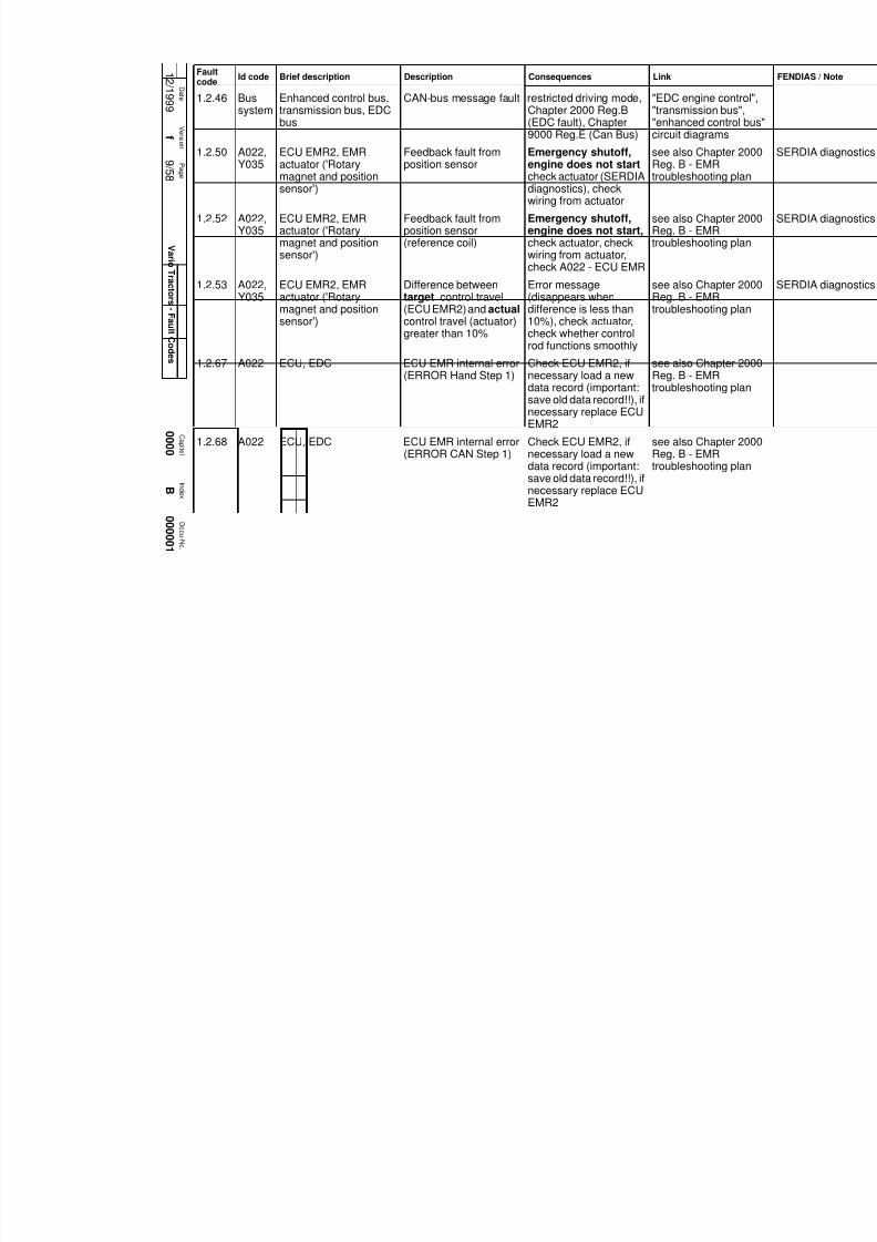
1.2.46 Bussystem
Enhanced control bus,transmission bus, EDCbus
CAN-bus message fault restricted driving mode,Chapter 2000 Reg.B(EDC fault), Chapter9000 Reg.E (Can Bus)
"EDC engine contro"transmission bus","enhanced control bcircuit diagrams
1.2.50 A022,Y035
ECU EMR2, EMRactuator ('Rotarymagnet and positionsensor')
Feedback fault fromposition sensor
Emergency shutoff,engine does not startcheck actuator (SERDIAdiagnostics), checkwiring from actuator
see also Chapter 20Reg. B - EMRtroubleshooting plan
1.2.52 A022,Y035
ECU EMR2, EMRactuator ('Rotarymagnet and positionsensor')
Feedback fault fromposition sensor(reference coil)
Emergency shutoff,engine does not start,check actuator, checkwiring from actuator,check A022 - ECU EMR
see also Chapter 20Reg. B - EMRtroubleshooting plan
1.2.53 A022,Y035
ECU EMR2, EMRactuator ('Rotary
magnet and positionsensor')
Difference betweentarget control travel
(ECU EMR2) and actualcontrol travel (actuator)greater than 10%
Error message(disappears when
difference is less than10%), check actuator,check whether controlrod functions smoothly
see also Chapter 20Reg. B - EMR
troubleshooting plan
1.2.67 A022 ECU, EDC ECU EMR internal error(ERROR Hand Step 1)
Check ECU EMR2, ifnecessary load a newdata record (important:save old data record!!), ifnecessary replace ECUEMR2
see also Chapter 20Reg. B - EMRtroubleshooting plan
1.2.68 A022 ECU, EDC ECU EMR internal error(ERROR CAN Step 1)
Check ECU EMR2, ifnecessary load a newdata record (important:save old data record!!), ifnecessary replace ECUEMR2
see also Chapter 20Reg. B - EMRtroubleshooting plan
Faultcode
Id code Brief description Description Consequences Link

7/17/2019 Failure codes fendt 900 Vario 09 2007
http://slidepdf.com/reader/full/failure-codes-fendt-900-vario-09-2007 14/201
1 2 / 1 9 9 9
0 0 0 0
0 0 0 0 0 1
B
f
1 0 / 5 8
C a pi t el
D o c u-N o.
I n d ex
D a t e
V er s i on
P a g e
V ar i o
T r a c t or s
- F a ul t C o d e s
1.2.70 A022 ECU, EDC CAN Bus controller fault possible reduced enginerunning characteristics--- check transmissionbus terminating resistors(A013 - circuit board,A009 - actuator unit),check ECU EMR2
also refer to Chapte2000 Reg.B (EMRTroubleshooting),Chapter 9000 Reg.(Can Bus)
1.2.71 A022,X810
ECU, EMR2 ;diagnostics socket
CAN interface fault possible reduced enginerunning characteristics--- check transmissionbus terminating resistors(A013 - circuit board,A009 - actuator unit),check ECU EMR2
see also Chapter 20Reg. B - EMRtroubleshooting plan
1.2.74 A022;A002
CAN bus, wiring (EMR) Cable broken, shortcircuit or serious CAN
bus fault; CAN buspassive
Running of engine maybe reduced
see also Chapter 20Reg. B - EMR
troubleshooting plan
1.2.76 A022 ECU EMR2 Parameter settingsincorrect
Emergency, enginedoes not start ---Switch ignition OFF thenON, check again, if errorreappears --> replaceECU EMR2
see also Chapter 20Reg. B - EMRtroubleshooting plan
1.2.77 A022 ECU EMR2 continuous monitoring ofprogram memorydelivers an error
Emergency, enginedoes not start ---Switch ignition OFF thenON, check again, if error
reappears --> replaceECU EMR2
see also Chapter 20Reg. B - EMRtroubleshooting plan
Faultcode
Id code Brief description Description Consequences Link

7/17/2019 Failure codes fendt 900 Vario 09 2007
http://slidepdf.com/reader/full/failure-codes-fendt-900-vario-09-2007 15/201
1 2 / 1 9 9 9
0 0 0 0
0 0 0 0 0 1
B
f
1 1 / 5 8
C a pi t el
D o c u-N o.
I n d ex
D a t e
V er s i on
P a g e
V ar i o
T r a c t or s- F a ul t C o d e s
1.2.78 A022 ECU EMR2 continuous monitoring ofprogram memorydelivers an error
Emergency, enginedoes not start ---Switch ignition OFF thenON, check again, if errorreappears --> replaceECU EMR2
see also Chapter 20Reg. B - EMRtroubleshooting plan
1.2.80 A022,Y035
ECU EMR2,EMR actuator
Voltage supply to EMRactuator out of allowedrange
Error message(disappears again whenthe current is in thenormal range), turnignition OFF and ONagain, recheck, if erroroccurs again --> replaceECU EMR2
also refer toChapter 2000 Reg. EMR Troubleshootinchecking cableharness
1.2.81 B038or B
055
EDC foot throttle rotaryposition sensor (yellow),
combi-sensor
Signal fault Chapter 2000 Reg.B(EDC fault)
'EDC control' circuitdiagram
1.2.82 A020 Pump control unit(injection pump) (EDC)
Fault in high-pressuresolenoid valve actuationtime
Engine stalls, Chapter2000 Reg.B (EDC fault)
'EDC control' circuitdiagram
1.2.83 A022 ECU EMR2 Reference voltage 1 forY035 - actuator out ofallowed range
Error message(disappears whencurrent is back in normalrange), substitute value5 VDC, check voltagesupply to ECU EMR2,switch ignition OFF thenON, if error reappears
--> replace ECU EMR2
see also Chapter 20Reg. B - EMRtroubleshooting plan
Faultcode
Id code Brief description Description Consequences Link

7/17/2019 Failure codes fendt 900 Vario 09 2007
http://slidepdf.com/reader/full/failure-codes-fendt-900-vario-09-2007 16/201
1 2 / 1 9 9 9
0 0 0 0
0 0 0 0 0 1
B
f
1 2 / 5 8
C a pi t el
D o c u-N o.
I n d ex
D a t e
V er s i on
P a g e
V ar i o
T r a c t or s
- F a ul t C o d e s
1.2.84(DEU-TZEMR)
A022 ECU EMR2 Reference voltage 2 forY035 - actuator out ofpermissible range
Error message(disappears whencurrent is back in normalrange), substitute value5 VDC, check voltagesupply to ECU EMR2,switch ignition OFF thenON, if error reappears--> replace ECU EMR2
see also Chapter 20Reg. B - EMRtroubleshooting plan
1.2.84(MANEDC)
B025 EDC speed sensor Signal fault Reduced power,Chapter 2000 Reg.B(EDC fault)
'EDC control' circuitdiagram
1.2.85(DEU-TZEMR)
A022 ECU EMR2 Reference voltage 4 forY035 - actuator out ofpermissible range
Error message(disappears whencurrent is back in normalrange), substitute value
5 VDC, check voltagesupply to ECU EMR2,switch ignition OFF thenON, if error reappears--> replace ECU EMR2
see also Chapter 20Reg. B - EMRtroubleshooting plan
1.2.85(MANEDC)
B028 Boost pressure sensor(EDC)
Signal fault Reduced power,Chapter 2000 Reg.B(EDC fault)
'EDC control' circuitdiagram
1.2.86 A022 ECU EMR2 Temperature in ECUEMR2 too high
Error message(disappears whentemperature is back innormal range), switch
ignition OFF then ON, iferror reappears -->replace ECU EMR2
see also Chapter 20Reg. B - EMRtroubleshooting plan
Faultcode
Id code Brief description Description Consequences Link

7/17/2019 Failure codes fendt 900 Vario 09 2007
http://slidepdf.com/reader/full/failure-codes-fendt-900-vario-09-2007 17/201
1 2 / 1 9 9 9
0 0 0 0
0 0 0 0 0 1
B
f
1 3 / 5 8
C a pi t el
D o c u-N o.
I n d ex
D a t e
V er s i on
P a g e
V ar i o
T r a c t or s- F a ul t C o d e s
1.2.87(DEU-TZEMR)
A022 ECU EMR2 Atmospheric pressuresensor in ECU EMR2faulty
Error message(disappears whenpressure is back innormal range), switchignition OFF then ON, iferror reappears -->replace ECU EMR2
see also Chapter 20Reg. B - EMRtroubleshooting plan
1.2.87(MANEDC)
B027 Water temperaturesensor (EDC)
Signal fault Reduced power,Chapter 2000 Reg.B(EDC fault)
'EDC control' circuitdiagram
1.2.89 A020 Pump control unit(injection pump)
Electronic volumecontroller fault
Engine won't start,Chapter 2000 Reg.B(EDC fault)
'EDC control' circuitdiagram
1.2.90 A022 ECU EMR2 Incorrect parameter(EEPROM reading, orchecksum error)
Engine does not start,switch ignition OFF thenON, if error reappears
--> replace ECU EMR2
see also Chapter 20Reg. B - EMRtroubleshooting plan
1.2.91 B025 EDC speed sensor Signal fault Reduced power,Chapter 2000 Reg.B(EDC fault)
'EDC control' circuitdiagram
1.2.92 A020A021
Engine control module,pump control unit(injection pump) (EDC)
Engine stop via 'Injectedvolume = 0' faulty, seeChapter 2710 Reg. A'Engine stop'
Reduced power,Chapter 2000 Reg.B(EDC fault)
'EDC control' circuitdiagram
1.2.93 A022 ECU EMR2 internal processing errorin ECU EMR2 (batchoverflow)
Emergency shutoff,engine does not start,switch ignition OFF then
ON, if error reappears--> load new data recordin ECU EMR2(important: save old datarecord!!) if errorreappears --> replaceECU EMR2
see also Chapter 20Reg. B - EMRtroubleshooting plan
Faultcode
Id code Brief description Description Consequences Link

7/17/2019 Failure codes fendt 900 Vario 09 2007
http://slidepdf.com/reader/full/failure-codes-fendt-900-vario-09-2007 18/201
1 2 / 1 9 9 9
0 0 0 0
0 0 0 0 0 1
B
f
1 4 / 5 8
C a pi t el
D o c u-N o.
I n d ex
D a t e
V er s i on
P a g e
V ar i o
T r a c t or s
- F a ul t C o d e s
1.2.94 A022 ECU EMR2 internal processing errorin ECU EMR2
Emergency shutoff,engine does not start,switch ignition OFF thenON, if error reappears--> load new data recordin ECU EMR2(important: save old datarecord!!) if errorreappears --> replaceECU EMR2
see also Chapter 20Reg. B - EMRtroubleshooting plan
1.2.96 A021 Engine control modulemonitoring unit (EDC)
Fault in EDC controlmodule monitoring unit(A021)
Engine stalls, Chapter2000 Reg.B (EDC fault)
'EDC control' circuitdiagram
1.2.99 A020A021
Engine control moduleand pump control unit(injection pump) (EDC)
Engine stop via powermonitor within EDCcontrol module, Chapter
2710 Reg.A 'EngineStop'.
Reduced power,Chapter 2000 Reg.B(EDC fault)
'EDC control' circuitdiagram
1.2.9B A020,A021
Engine control module,pump control unit(injection pump) (EDC)
Engine stop via enginestop solenoid valve,Chapter 2710 Reg.AEngine Stop
Reduced power,Chapter 2000 Reg.B(EDC fault)
'EDC control' circuitdiagram
1.2.A2 K021 Relay "solenoid valveshut-off" (EDC)
Engine stop via relayK021, Chapter 2710Reg.A Engine Stop
Reduced power,Chapter 2000 Reg.B(EDC fault)
'EDC control' circuitdiagram
1.2.A6 A021,A020
Engine control module,pump control unit(injection pump) (EDC)
Engine stop, fault insignal processing inEDC control module
Reduced power,Chapter 2000 Reg.B(EDC fault)
'EDC control' circuitdiagram
1.2.A8 A021 Engine control module(EDC)
Fault in barometricpressure sensor
Chapter 2000 Reg.B(EDC fault)
1.2.A9 A020 Pump control unit(injection pump) (EDC)
Fault identified duringself-diagnostic test
Reduced power, enginewon't start, Chapter2000 Reg.B (EDC fault)
Faultcode
Id code Brief description Description Consequences Link

7/17/2019 Failure codes fendt 900 Vario 09 2007
http://slidepdf.com/reader/full/failure-codes-fendt-900-vario-09-2007 19/201
1 2 / 1 9 9 9
0 0 0 0
0 0 0 0 0 1
B
f
1 5 / 5 8
C a pi t el
D o c u-N o.
I n d ex
D a t e
V er s i on
P a g e
V ar i o
T r a c t or s- F a ul t C o d e s
1.2.B1 A021,A020
Engine control module,pump control unit(injection pump) (EDC)
EDC CAN message:fault between EDCcontrol module andpump control unit
Reduced power,Chapter 2000 Reg.B(EDC fault)
'EDC control' circuitdiagram
1.2.B2 A020 Pump control unit(injection pump) (EDC)
Fault identified duringself-diagnostic test
Reduced power,Chapter 2000 Reg.B(EDC fault)
1.2.B3 A020 Pump control unit(injection pump) (EDC)
Fault in pump controlunit power supply.Chapter 2710 Reg.A'Engine stop'.
Engine stalls, enginewon't start, Chapter2000 Reg.B (EDC fault)
'EDC control' circuitdiagram
1.2.B4 A020A021
Engine control module,pump control unit(injection pump) (EDC)
CAN message: faultbetween pump controlunit and engine controlmodule
Engine idling, Chapter2000 Reg.B (EDC fault)
'EDC control' circuitdiagram
1.2.B5 A020 Pump control unit(injection pump) (EDC) Fault during pumpcontrol unitself-diagnostic test(EEPROM checksum)
Reduced power,Chapter 2000 Reg.B(EDC fault)
1.2.B6 A020 Pump control unit(injection pump) (EDC)
Fault during pumpcontrol unitself-diagnostic test(EEPROM status)
Reduced power,Chapter 2000 Reg.B(EDC fault)
1.2.B7 A020,B025
Pump control unit(injection pump), enginespeed sensor (EDC)
Fault in speed signal topump control unit, signalprocessing fault in pumpcontrol unit
Reduced power,Chapter 2000 Reg.B(EDC fault)
'EDC control' circuitdiagram
1.2.B9 A020 Pump control unit(injection pump) (EDC)
Fault during injectionpump self-diagnostictest (RAM fault)
Engine stops. Chapter2000 Reg.B (EDC fault)
Faultcode
Id code Brief description Description Consequences Link

7/17/2019 Failure codes fendt 900 Vario 09 2007
http://slidepdf.com/reader/full/failure-codes-fendt-900-vario-09-2007 20/201
1 2 / 1 9 9 9
0 0 0 0
0 0 0 0 0 1
B
f
1 6 / 5 8
C a pi t el
D o c u-N o.
I n d ex
D a t e
V er s i on
P a g e
V ar i o
T r a c t or s
- F a ul t C o d e s
1.2.C1 A020 Pump control unit(injection pump) (EDC)
Fault during pumpcontrol unitself-diagnostic test(solenoid valve outputstage)
Chapter 2000 Reg.B(EDC fault)
Fault only whenstarting - checkbatteries
1.2.C3 A021,A020
Engine control module,pump control unit(injection pump) (EDC)
CAN message: faultbetween engine controlmodule and pumpcontrol unit when enginestarts
Engine idling (720 rpm),Chapter 2000 Reg.B(EDC fault)
'EDC control' circuitdiagram
1.2.C4 A020 Pump control unit(injection pump) (EDC)
Fault in CANcommunication to pumpcontrol unit
Engine idling (720 rpm),Chapter 2000 Reg.B(EDC fault)
'EDC control' circuitdiagram
1.2.C5 A021,A020
Engine control module,pump control unit(injection pump) (EDC)
Fault in engine stop viaengine stop solenoidvalve, Chapter 2710
Reg.A Engine Stop
Reduced power,Chapter 2000 Reg.B(EDC fault)
'EDC control' circuitdiagram
1.2.C7 A020 Pump control unit(injection pump) (EDC)
Pump speed sensorfault (IWZ signal)
Engine stops. Chapter2000 Reg.B (EDC fault)
Fault only whenstarting - checkbatteries
1.2.C8 A021,B026,B028
EDC CAN BUS,engine control module,needle movementsensor, boost pressuresensor (EDC)
Engine control module:injection quantitycalculation inaccurate
Engine stalls, Chapter2000 Reg.B (EDC fault)
'EDC control' circuitdiagram
1.2.C9 A020 Pump control unit(injection pump) (EDC)
Fault during pumpcontrol unit
self-diagnostic test(solenoid valve outputstage)
Chapter 2000 Reg.B(EDC fault)
Fault only whenstarting - check
batteries
1.2.CA A020 Pump control unit(injection pump) (EDC)
Injection controller out ofrange
Reduced power,Chapter 2000 Reg.B(EDC fault)
Check primary presand interior pressurpump
Faultcode
Id code Brief description Description Consequences Link

7/17/2019 Failure codes fendt 900 Vario 09 2007
http://slidepdf.com/reader/full/failure-codes-fendt-900-vario-09-2007 21/201
1 2 / 1 9 9 9
0 0 0 0
0 0 0 0 0 1
B
f
1 7 / 5 8
C a pi t el
D o c u-N o.
I n d ex
D a t e
V er s i on
P a g e
V ar i o
T r a c t or s- F a ul t C o d e s
1.2.CB A021,A020
Engine control module,pump control unit(injection pump) (EDC)
Fault in CANcommunication to pumpcontrol unit
Engine idling,Chapter 2000 Reg.B(EDC fault)
'EDC control' circuitdiagram
1.2.CD A021,
A020
Engine control module,
pump control unit(injection pump) (EDC)
Fault in propagation time
of CAN communicationbetween pump controlunit and EDC controlmodule
Reduced power,
Chapter 2000 Reg.B(EDC fault)
1.2.DE A002,A021
Enhanced controlmodule, engine controlmodule (EDC)
Propagation time ofCAN communicationmissing
Restricted operatingmode, Chapter 2000Reg.B (EDC fault)
1.2.E0 A021,A002
Engine control module,enhanced controlmodule (EDC)
Fault during CANcommunication betweenEDC control module andenhanced controlmodule
Chapter 2000 Reg.B(EDC fault) Chapter9000 Reg.E (Can Bus)
'EDC engine contro'transmission bus' cidiagram
1.2.E1 Fault in speed signal(B014 - sensor,accumulator shaft, B015- sensor - bevel pinion)or PTO is driving engine(running on)
Fault display,Chapter 2000 Reg.B(EDC fault)
2.1.E0 A002,A034
ECU, enhanced controlJoystick
CAN communicationfault between ECUenhanced control anddrive switch
Emergency operation --check enhanced controlbus (Chapter 9000Reg.E)
2.1.EE ISO/LBS implement Fault in LBS ECU Mounted implement can
no longer be operatedvia joystick controls orterminal.
2.1.EF ISO/LBS implement Limited operation ofimplement, dependingon manufacturer
For fault descriptionplease see implememanufacturer's litera
Faultcode
Id code Brief description Description Consequences Link

7/17/2019 Failure codes fendt 900 Vario 09 2007
http://slidepdf.com/reader/full/failure-codes-fendt-900-vario-09-2007 22/201
1 2 / 1 9 9 9
0 0 0 0
0 0 0 0 0 1
B
f
1 8 / 5 8
C a pi t el
D o c u-N o.
I n d ex
D a t e
V er s i on
P a g e
V ar i o
T r a c t or s
- F a ul t C o d e s
3.1.01 A004 Control console Internal RAM, EEPROMfaults
Functions switched off: -button panel, - digital / analogue inputs, - LEDactuation
Fit new control cons
3.1.02 A004 Control console Internal RAM, EEPROMfaults
Functions switched off: -button panel, - digital / analogue inputs, - LEDactuation
Fit new control cons
3.1.03 A004 Control console Internal RAM, EEPROMfaults
Functions switched off: -button panel, - digital / analogue inputs, - LEDactuation
Fit new control cons
3.1.04 A004 Control console Internal RAM, EEPROMfaults
Functions switched off: -button panel, - digital / analogue inputs, - LEDactuation
Fit new control cons
3.1.05 A004 Control console Internal 8.5 V fault,keypad fault
Functions switched off: -button panel, - digital / analogue inputs, - LEDactuation
Fit new control cons
3.1.06 A004 Control console External 8.5 V fault Functions switched off: -button panel, - digital / analogue inputs, - LEDactuation
Fit new control cons
4.1.01 A003,A034
Acceleration ramp I-IV Signal fault Continuation inemergency modepossible
8.5 V supply fault A013 fuse 5
4.1.03 Neumaier reverse drivefacility clutch pedalpotentiometer
Signal fault Continuation inemergency modepossible
8.5 V supply fault A013 fuse 9
Faultcode
Id code Brief description Description Consequences Link

7/17/2019 Failure codes fendt 900 Vario 09 2007
http://slidepdf.com/reader/full/failure-codes-fendt-900-vario-09-2007 23/201
1 2 / 1 9 9 9
0 0 0 0
0 0 0 0 0 1
B
f
1 9 / 5 8
C a pi t el
D o c u-N o.
I n d ex
D a t e
V er s i on
P a g e
V ar i o
T r a c t or s- F a ul t C o d e s
4.1.04 B017 Clutch pedal rotaryposition sensor
Signal fault Loss of enhancedcontrol / function in finalspeed control; cruisecontrol does notfunction, TMS isswitched off
'Transmission contrcircuit diagram
8.5 V supply fault A013 fuse 8
4.1.05 B039 High pressure sensor II(push detection)
Signal fault Loss of enhancedcontrol functions duringdrive operation ( no'active parking function')
12 V supply fault A013 fuse 2
4.1.06(withmech.
engin-econtr-ol)
B018 Target engine speedposition sensor
Signal fault Continuation inemergency modepossible
'Transmission contrcircuit diagram
8.5 V supply fault A013 fuse 14
4.1.06(forEDC orEMR)
B029orB055
EST foot throttle rotaryposition sensor (red),combi-sensor
Signal fault Restricted operation (nohand throttle, nomemory keys)
'EDC control' circuitdiagram
8.5 V supply fault A013 fuse 17
4.1.07 B008 Transmission drivepressure high-pressuresensor
Signal fault Shifting from drivingmode 1 to 2 notpossible, TMS isswitched off
'Transmission contrcircuit diagram
8.5 V supply fault A013 fuse 3
4.1.08 B016 Actual speed rangeposition sensor
Signal fault Not possible to changebetween driving modes;current driving mode ismaintained
'Transmission contrcircuit diagram
8.5 V supply fault A013 fuse 13
Faultcode
Id code Brief description Description Consequences Link

7/17/2019 Failure codes fendt 900 Vario 09 2007
http://slidepdf.com/reader/full/failure-codes-fendt-900-vario-09-2007 24/201
1 2 / 1 9 9 9
0 0 0 0
0 0 0 0 0 1
B
f
2 0 / 5 8
C a pi t el
D o c u-N o.
I n d ex
D a t e
V er s i on
P a g e
V ar i o
T r a c t or s
- F a ul t C o d e s
4.1.20 A002,A034
ECU, enhanced controlJoystick
Accelerator pedalrelease pot. ('Slideswitch') not calibrated orEEPROM checksumerror
Driving in acceleratorpedal mode not possible
4.1.21 S045 'Reverse operationsensor' solenoid switch
Signal fault
4.1.22 A034 Joystick Accelerator pedalrelease pot. ('Slideswitch') faulty
Accelerator pedal modenot functioning
4.1.23 A003,A034
Joystick 'cruise controlON'
Signal fault Continuation inemergency modepossible
'Transmission contrcircuit diagram
4.1.24 S015 Hand brake solenoidswitch
Signal fault Hand brake automaticmode not available
'Transmission contrcircuit diagram
4.1.25 A003,A034
Joystick 'Rapidreversing'
Signal fault Continuation inemergency modepossible
'Transmission contrcircuit diagram
4.1.26 A034 Joystick Joystick signal'accelerator pedal mode'faulty
Accelerator pedal modenot functioning
4.1.27 A034 Joystick Rapid reverse button(F/R rocker) fault
F/R rocker in the armrestnot functioning
(joystick lock)
4.1.28 A009 Transmission controlunit, F/R incrementalencoder
Signal fault Continuation inemergency modepossible
'Transmission contrcircuit diagram
4.1.29 A003,A034
Joystick 'Rest position' Signal fault Continuation inemergency modepossible
'Transmission contrcircuit diagram
4.1.2A B015 Bevel pinion direction(=direction of travel) Hallsensor
Signal fault Continuation inemergency modepossible
'Transmission contrcircuit diagram
Faultcode
Id code Brief description Description Consequences Link

7/17/2019 Failure codes fendt 900 Vario 09 2007
http://slidepdf.com/reader/full/failure-codes-fendt-900-vario-09-2007 25/201
1 2 / 1 9 9 9
0 0 0 0
0 0 0 0 0 1
B
f
2 1 / 5 8
C a pi t el
D o c u-N o.
I n d ex
D a t e
V er s i on
P a g e
V ar i o
T r a c t or s- F a ul t C o d e s
4.1.2B A003,A034
Button for driving modeselection
Signal fault Actual driving mode ismaintained; switching isnot possible
'Transmission contrcircuit diagram
4.1.2C A003,
A034
Button to toggle
between 'Neutral / Active stationary mode'
Signal fault Continuation in
emergency modepossible
'Transmission contr
circuit diagram
4.1.2D S014orS061
'Rapid reversing' controlon control stalk
Signal fault Rapid reversing stillpossible via joystick
'Transmission contrcircuit diagram
4.1.2E A003,A034
'v+ transmission control'(joystick forwards)
Signal fault Continuation inemergency modepossible
'Transmission contrcircuit diagram
4.1.2F A003 'v- transmission control'(joystick to rear)
Signal fault Continuation inemergency modepossible
'Transmission contrcircuit diagram
4.1.30 MS 'Emergency mode hatch'solenoid switch
Signal fault Continuation inemergency modepossible
4.1.31 B014 Hall sensor foraccumulator shaftdirection (partially alsodefined by 'Hydrostat')
Signal fault Continuation inemergency modepossible
'Transmission contrcircuit diagram
4.1.32 A003,A034
'Activating key' within joystick
Signal fault Continuation inemergency modepossible
'Transmission contrcircuit diagram
4.1.33 'Automatic maximum
output control' key onmembrane keypad
Signal fault Function not available
4.1.34 'Cruise control' key onmembrane keypad
Signal fault Function not available
4.1.35 'Store reversetransmission ratio' keyon membrane keypad
Signal fault Function not available
Faultcode
Id code Brief description Description Consequences Link

7/17/2019 Failure codes fendt 900 Vario 09 2007
http://slidepdf.com/reader/full/failure-codes-fendt-900-vario-09-2007 26/201
1 2 / 1 9 9 9
0 0 0 0
0 0 0 0 0 1
B
f
2 2 / 5 8
C a pi t el
D o c u-N o.
I n d ex
D a t e
V er s i on
P a g e
V ar i o
T r a c t or s
- F a ul t C o d e s
4.1.36 'Rear PTO automatic'key on membranekeypad
Signal fault Function not available
4.1.37 'Front PTO automatic'
key on membranekeypad
Signal fault Function not available
4.1.38 'Store forwardtransmission ratio' keyon membrane keypad
Signal fault Function not available
4.1.41 B011 Engine speed Hallsensor 2
Signal fault Continuation inemergency modepossible
'Transmission contrcircuit diagram
12 V supply fault A013 fuse 2
4.1.42 B014 Hall sensor foraccumulator shaft speed
(partially also defined by'Hydrostat')
Signal fault Continuation inemergency mode
possible
'Transmission contrcircuit diagram
8.5 V supply fault A013 fuse 16
4.1.44 B010 Engine speed Hallsensor 1
Signal fault Continuation inemergency modepossible
'Transmission contrcircuit diagram
12 V supply fault A013 fuse 4
4.1.45 B015 Bevel pinion speed(=travel speed) Hallsensor
Signal fault Continuation inemergency modepossible
'Transmission contrcircuit diagram
8.5 V supply fault A013 fuse 7
4.1.50 S017 'Transmission oil filterclogged' switch
Filter clogged No further indication ofclogging
'Transmission contrcircuit diagram
Faultcode
Id code Brief description Description Consequences Link

7/17/2019 Failure codes fendt 900 Vario 09 2007
http://slidepdf.com/reader/full/failure-codes-fendt-900-vario-09-2007 27/201
1 2 / 1 9 9 9
0 0 0 0
0 0 0 0 0 1
B
f
2 3 / 5 8
C a pi t el
D o c u-N o.
I n d ex
D a t e
V er s i on
P a g e
V ar i o
T r a c t or s- F a ul t C o d e s
4.1.53 B009 Thermo switch 'Transmission oiltemperature more than110°C'
Continuing to drive willcause transmissiondamage!
'Transmission contrcircuit diagram
4.1.56 S017 'Transmission oil filter
clogged' switch
Signal fault No further display! 'Transmission contr
circuit diagram
4.1.58 Transmission slipmonitor
Transmission outputspeed deviates by morethan 30% from setpoint
may occur at extremelylow temperatures inisolated cases; repeatedoccurrence undernormal conditionsresults in a rise in oiltemperature andtransmissiondamage;TMS isswitched off
Fault not active if -turboclutch functionon - clutch is depres
4.1.59 'Emergency operation'actuation
Emergency operationactivated manuallywithout apparent reason
Fault in emergencymode
4.1.61 Y002 'Shifting from speedrange 2 to 1' solenoidvalve
Actuation fault Continuation inemergency modepossible
'Transmission contrcircuit diagram
4.1.62 Y003 'Shifting from speedrange 1 to 2' solenoidvalve
Actuation fault Continuation inemergency modepossible
4.1.63 Y005 'Speed governor'solenoid valve (=limitingangle of rotation ofactuator shaft)
Actuation fault Possible to continue atmax. 30 km/h
'Transmission contrcircuit diagram
4.1.64 Y004 Turboclutch solenoidvalve
PWM actuation fault 'Transmission contrcircuit diagram
Faultcode
Id code Brief description Description Consequences Link

7/17/2019 Failure codes fendt 900 Vario 09 2007
http://slidepdf.com/reader/full/failure-codes-fendt-900-vario-09-2007 28/201
1 2 / 1 9 9 9
0 0 0 0
0 0 0 0 0 1
B
f
2 4 / 5 8
C a pi t el
D o c u-N o.
I n d ex
D a t e
V er s i on
P a g e
V ar i o
T r a c t or s
- F a ul t C o d e s
4.1.65 Y006;
Y051
'Engine brake' solenoidvalve;Relay cardan brake
Actuation fault
4.1.66 K051,
Y053
Relay, active parking
function,solenoid valve, activeparking function
Relay faulty, solenoid
valve faulty, signaltransmission faulty
No active parking
function
"Engine brake and
active parking functcircuit diagram
4.1.67 K051 Relay, active parkingfunction
Relay test not required,relay contacts (Pin 3 / 5)stuck.
No active parkingfunction.
'Engine brake and aparking function' cirdiagram
4.1.70 A004 'Cruise control 1' key Key fault Cruise control cannot beactivated
'Transmission contrcircuit diagram
Bus fault from A004 totransmission controlmodule
4.1.71 A004 'Cruise control 2' key Key fault Cruise control cannot beactivated
'Transmission contrcircuit diagram
Bus fault from A004 totransmission controlmodule
4.1.72 S017 'Transmission oil filterclogged' switch
Signal fault No further display ormonitoring, possiblytransmission damage
'Transmission contrcircuit diagram
4.1.73 B033 'Discharge oiltemperature' sensor
Signal fault No further display ormonitoring, possiblytransmission damage
'Transmission contrcircuit diagram
4.1.74 S015 'Hand brake ON/OFFsensor' solenoid switch
Signal fault TMS is switched off 'Transmission contrcircuit diagram
4.1.75 S045 'Reverse operationsensor' solenoid switch
Signal fault 'Transmission contrcircuit diagram
4.1.76 S047 Engine brakeplunger-operated switch
Signal fault TMS is switched off 'Transmission contrcircuit diagram
Faultcode
Id code Brief description Description Consequences Link

7/17/2019 Failure codes fendt 900 Vario 09 2007
http://slidepdf.com/reader/full/failure-codes-fendt-900-vario-09-2007 29/201
1 2 / 1 9 9 9
0 0 0 0
0 0 0 0 0 1
B
f
2 5 / 5 8
C a pi t el
D o c u-N o.
I n d ex
D a t e
V er s i on
P a g e
V ar i o
T r a c t or s- F a ul t C o d e s
4.1.77 A034 Joystick Switch, accelerationramp I ... IV faulty
Only acceleration rate IIIavailable
4.1.78 S053 Seat switch Signal fault from seatswitch
Selection of direction oftravel is disabled in
accelerator pedal modewhen vehicle isstationary (the tractordriver must re-activatethe selection of directionof travel)
4.1.7E B035 Setpoint engine speedEDC/EMR rotaryposition sensor, 'handthrottle potentiometer'
Signal fault 'EDC control' circuitdiagram
4.1.7F A003,A034
Memory key MIN/ MAXsetpoint engine speed
EDC/EMR
Signal fault 'EDC control' circuitdiagram
4.1.81 B010B011
Engine speed Hallsensor 1/2
Plausibility error(=speeds do not match)
Continuation inemergency modepossible
'Transmission contrcircuit diagram
4.1.82 B014B015B016
Drive collector shaft rpmHall sensor / drivingmode detection bevelpinion sensor
Plausibility error(=speeds do not match)
Continuation inemergency modepossible
'Transmission contrcircuit diagram
4.1.83 B014B015
Accumulator shaft/bevelpinion speed Hall sensor
Plausibility error(=speeds do not match)
Continuation inemergency mode
possible
'Transmission contrcircuit diagram
4.1.84 A003orA034
Joystick switch (V, R,VR, cruise control,default position)
Plausibility error(=signals do not matchlogically)
Continuation inemergency modepossible
'Transmission contrcircuit diagram
Faultcode
Id code Brief description Description Consequences Link

7/17/2019 Failure codes fendt 900 Vario 09 2007
http://slidepdf.com/reader/full/failure-codes-fendt-900-vario-09-2007 30/201
1 2 / 1 9 9 9
0 0 0 0
0 0 0 0 0 1
B
f
2 6 / 5 8
C a pi t el
D o c u-N o.
I n d ex
D a t e
V er s i on
P a g e
V ar i o
T r a c t or s
- F a ul t C o d e s
4.1.85 B010 Engine speed Hallsensor 1
Engine speed sensordoes not supplyplausible speed curves.Output speed increaseor decrease is outsidelimits.
Continuation inemergency modepossible
'Transmission contrcircuit diagram
4.1.86 B008,B039
High pressure sensor I(transmission drivepressure) ; Highpressure sensor II (pushdetection)
Plausibility errorbetween B008 sensorand B039 sensor
Loss of enhancedcontrol when driving('Active parking functionnot functioning'), TMS isswitched off
4.1.87 S061 Switch, rapid reverse onthe steering wheeladjustment
Plausibility error at the F / R switch, rapid reverse
F / R switch notfunctioning, rapidreverse on the steeringwheel adjustment lever,S061- switch,
Check rapid reverseChapter 9000 Reg.
4.1.88 A034 Joystick Plausibility error at theON / OFF key of theaccelerator pedal mode
Key not functioning
4.1.90 A001A004
Cruise control 1 - datacommunication
Data communicationfault
Key not available
4.1.91 A001A004
Cruise control 2 - datacommunication
Data communicationfault
Key not available
4.1.92 A001A002
Brake pedal left / right,data communication
Data communicationfault
Automatic cruise controlnot available
4.1.93 A001A002
Brake pedal left, datacommunication
Data communicationfault
Automatic cruise controlnot available
4.1.94 A034 Joystick CAN communicationfault between A002 -ECU, enhanced controland A034 - joystick
Joystick functionslimited.
Faultcode
Id code Brief description Description Consequences Link

7/17/2019 Failure codes fendt 900 Vario 09 2007
http://slidepdf.com/reader/full/failure-codes-fendt-900-vario-09-2007 31/201
1 2 / 1 9 9 9
0 0 0 0
0 0 0 0 0 1
B
f
2 7 / 5 8
C a pi t el
D o c u-N o.
I n d ex
D a t e
V er s i on
P a g e
V ar i o
T r a c t or s- F a ul t C o d e s
4.1.A0 A009 Transmission controlunit
Actuation fault intransmission controlmodule
Continuation inemergency modepossible
4.1.A1 A009 Transmission control
unit
Turn angle is not
reached within 2seconds.
Continuation in
emergency modepossible
Mechanical test: Ch
smooth adjustmentaction in emergencyoperation
4.1.A2 A009A001orA002
Transmission controlunit
CAN-bus actuation fault Continuation inemergency modepossible
Chapter 9000 Reg. Testing CAN - BUS
4.1.A3 A009 Transmission controlunit
Fault or logical error inincremental sensorsignal (actual positionsignal)
Continuation inemergency modepossible
4.1.A4 A009 Transmission controlunit
Fault or logical error inECU signal.
Continuation inemergency modepossible
4.1.A5 A009 Transmission controlunit
Initial reference (=zeroposition) could not bereached during ignition'ON'
Continuation inemergency modepossible
4.1.A6 A009 Transmission controlunit
Reference point signalfault during operation
Continuation inemergency modepossible
4.1.B0 all Bus users Initialisation error Restricted CAN-busdata communication
Chapter 9000 Reg. Testing CAN BUS
4.1.B1 Y001Y002
Speed range control Illogical speed rangeoperation (=fatal error)
Continuation inemergency modepossible
Faultcode
Id code Brief description Description Consequences Link

7/17/2019 Failure codes fendt 900 Vario 09 2007
http://slidepdf.com/reader/full/failure-codes-fendt-900-vario-09-2007 32/201
1 2 / 1 9 9 9
0 0 0 0
0 0 0 0 0 1
B
f
2 8 / 5 8
C a pi t el
D o c u-N o.
I n d ex
D a t e
V er s i on
P a g e
V ar i o
T r a c t or s
- F a ul t C o d e s
4.1.B2 A002 ECU, enhanced control Fault in EPROMprogramming (drivingmode selector I / II)
Range cannot bechanged while driving.
4.1.B3 A002 ECU, enhanced control Fault in EPROM
programming (rapidreversing rampparameters)
Rapid reversing possible
with standard values.
4.1.B4 B010 Sensor, engine 1 Input parameter valuesfor plausibilitymonitoring are incorrect.
Standard parametersare stored, plausibilitymonitoring systemremains functional.
4.1.B5 A002 ECU, enhanced control Checksum error rampparameter, rapid reversefor Tractor ManagementSystem (TMS)
4.1.B6 Equipment 'Neumaierreverse drive facility' Neumaier reverse drivefacility has failed or isfaulty
4.1.E0 Y004 Turboclutchcharacteristic
Wrong characteristicstored
Continuation inemergency modepossible
4.1.E1 A002 ECU, enhanced control Pressure regulatorcontrol parameters intractive power control(ML - transmissionadjustment) notplausible or read
incorrectly4.1.E2 A002 ECU, enhanced control Pressure regulator
control parameters intractive power controlnot plausible (B008 / B039) or readincorrectly.
Faultcode
Id code Brief description Description Consequences Link

7/17/2019 Failure codes fendt 900 Vario 09 2007
http://slidepdf.com/reader/full/failure-codes-fendt-900-vario-09-2007 33/201
1 2 / 1 9 9 9
0 0 0 0
0 0 0 0 0 1
B
f
2 9 / 5 8
C a pi t el
D o c u-N o.
I n d ex
D a t e
V er s i on
P a g e
V ar i o
T r a c t or s- F a ul t C o d e s
4.1.E3 A002 ECU, enhanced control Checksum errorparameter foraccelerator pedal mode
TMS is switched off
4.1.E4 A002 ECU, enhanced control Checksum error
parameter for activeparking function
4.1.E8 Equipment 'Neumaierreverse drive facility'
Checksum error onclutch pedalpotentiometer onNeumaier reverse drivefacility or clutchcalibration faulty
4.1.E9 B016 Values for shift fromrange II to I outsidetolerances
Shifting only possiblewhen stationary
4.1.EA A002 Internal fault (RAM / EEPROM) Continuation inemergency modepossible
4.1.EB B016 Speed range operation No calibration or driftedvalues
Continuation inemergency modepossible
4.1.EC B029,B038orB055
Specified engine speedrotary position sensor('accelerator pedal')combi-sensor
No calibration or driftedvalues
Continuation inemergency modepossible
4.1.ED B017 Clutch pedal rotaryposition sensor
No calibration or driftedvalues
Continuation inemergency modepossible
4.1.EE A002 Transmissioncharacteristic
No calibration or driftedvalues
Continuation inemergency modepossible
Faultcode
Id code Brief description Description Consequences Link

7/17/2019 Failure codes fendt 900 Vario 09 2007
http://slidepdf.com/reader/full/failure-codes-fendt-900-vario-09-2007 34/201
1 2 / 1 9 9 9
0 0 0 0
0 0 0 0 0 1
B
f
3 0 / 5 8
C a pi t el
D o c u-N o.
I n d ex
D a t e
V er s i on
P a g e
V ar i o
T r a c t or s
- F a ul t C o d e s
4.1.EF A002 Turboclutchcharacteristic
No calibration or driftedvalues
Continuation inemergency modepossible
4.1.FF A001A002
Transmission e-box Internal fault (RAM / EEPROM)
Continuation inemergency modepossible
5.1.00 A002 ECU, enhanced control EEPROM checksumerror
5.1.31 A004 4WD 100% key Key/A004 signal fault Other functions remainactive
'4WD / Diff. Lock' cidiagram
Bus fault A004 / A002
5.1.32 A004 4WD automatic key Key/A004 signal fault Other functions remainactive
'4WD / Diff. Lock' cidiagram
Bus fault A004 / A002
5.1.33 Y009 4WD clutch solenoidvalve
Actuation fault 4WD engages '4WD / Diff. Lock' cidiagram
5.1.34 B047 Proximity sensor -steering angle sensor 1
Signal / switch fault 4WD/diff. lock automaticsystem out of order
'4WD / Diff. Lock' cidiagram
5.1.35 B047 Proximity sensor -steering angle sensor 2
Signal / switch fault 4WD/diff. lock automaticsystem out of order
'4WD / Diff. Lock' cidiagram
5.1.51 A004 Diff. lock 100% key Key/A004 signal fault Other functions remainactive
'4WD / Diff. Lock' cidiagram
Bus fault A004 / A002
5.1.52 A004 Diff. lock automaticsystem key Key/A004 signal fault Other functions remainactive '4WD / Diff. Lock' cidiagram
Bus fault A004 / A002
5.1.53 Y010 Diff. lock solenoid valve Actuation fault Diff. lock disengages '4WD / Diff. Lock' cidiagram
Faultcode
Id code Brief description Description Consequences Link

7/17/2019 Failure codes fendt 900 Vario 09 2007
http://slidepdf.com/reader/full/failure-codes-fendt-900-vario-09-2007 35/201
1 2 / 1 9 9 9
0 0 0 0
0 0 0 0 0 1
B
f
3 1 / 5 8
C a pi t el
D o c u-N o.
I n d ex
D a t e
V er s i on
P a g e
V ar i o
T r a c t or s- F a ul t C o d e s
5.1.54 S006 Left brake pedalsolenoid switch
Signal fault Differential lockautomatic mode nolonger available, TMS isswitched off
'4WD / Diff. Lock' cidiagram
5.1.55 S005 Right brake pedalsolenoid switch
Signal fault Differential lockautomatic mode nolonger available, TMS isswitched off
'4WD / Diff. Lock' cidiagram
5.1.61 B003 Suspension positionsensor
Signal fault No further functionsavailable, suspensionremains in last position.Continuation withoutsuspension possible
'Suspension' circuitdiagram
8.5 V supply fault A013 fuse 18
5.1.62 Y014 'Raise' suspension
solenoid valve
12V supply fault No further functions
available, suspensionremains in last position.Continuation withoutsuspension possible
'Suspension' circuit
diagram
5.1.63 Y013 'Lower' suspensionsolenoid valve
12V supply fault No further functionsavailable, suspensionremains in last position.Continuation withoutsuspension possible
'Suspension' circuitdiagram
5.1.64 A004 'Suspension ON' key Fault in signal from keyto A004
Suspension notoperational.Continuation without
suspension possibleFault in bus signal fromA004 to A002
'CAN/enhanced conbus' circuit diagram
Faultcode
Id code Brief description Description Consequences Link

7/17/2019 Failure codes fendt 900 Vario 09 2007
http://slidepdf.com/reader/full/failure-codes-fendt-900-vario-09-2007 36/201
1 2 / 1 9 9 9
0 0 0 0
0 0 0 0 0 1
B
f
3 2 / 5 8
C a pi t el
D o c u-N o.
I n d ex
D a t e
V er s i on
P a g e
V ar i o
T r a c t or s
- F a ul t C o d e s
5.1.65 A004 'Suspension OFF / Lock'key
Fault in signal from keyto A004
Suspension notoperational.Continuation withoutsuspension possible
Fault in bus signal fromA004 to A002
'CAN/enhanced conbus' circuit diagram
5.1.66 Y012 Valve, chargesuspension
Actuation fault Suspension moves to'Lock' status.
5.1.6E B003 Suspension positionsensor
Incorrect calibration Suspension notoperational
5.1.8D A002 ECU, enhanced control Checksum error oldconfig data
Limited enhancedcontrol operation
5.1.8F A002 ECU, enhanced control Checksum error oldautomatic mode
sequence data
Limited enhancedcontrol operation
5.1.91 A003,A034
'Rear automatic ON / OFF' key in joystick
Signal fault Rear automatic notfunctioning
5.1.93 A003,A034
'Front automatic ON / OFF' key in joystick
Signal fault Front automatic notfunctioning
5.1.95 A003,A034
'Automatic functionsSTOP' key in joystick
Signal fault Automatic stop notfunctioning
5.1.98 S025 LS pumppressure-operatedswitch
Minimum pressure is notreached
Valve may lock orquantity may be reduced
El. valves 1"circuitdiagram", also referChapter 9000 Reg.
5.1.99 S026 Auxiliary pump flowmonitor Minimum quantity is notreached Control valve quantityautomatically reduced to20 l/min.
El. valves 1'circuitdiagram', also refer Chapter 9000 Reg.
5.1.99 S025,S026
LS pumppressure-operatedswitch, auxiliary pumpflow monitor
Short to ground in thesignal line
No monitoring for eitherpump.
El. valves 1'circuitdiagram', also refer Chapter 9000 Reg.
Faultcode
Id code Brief description Description Consequences Link

7/17/2019 Failure codes fendt 900 Vario 09 2007
http://slidepdf.com/reader/full/failure-codes-fendt-900-vario-09-2007 37/201
1 2 / 1 9 9 9
0 0 0 0
0 0 0 0 0 1
B
f
3 3 / 5 8
C a pi t el
D o c u-N o.
I n d ex
D a t e
V er s i on
P a g e
V ar i o
T r a c t or s- F a ul t C o d e s
5.1.9A S026 Auxiliary pump flowmonitor
Switch faulty (doesn'tclose / is open evenwithout oil volume)
Plausibility error (wrongvoltage value / Ohmvalue)
El. valves 1'circuitdiagram', also refer Chapter 9000 Reg.
5.1.9B S025,S026
LS pumppressure-operatedswitch, auxiliary pumpflow monitor
While engine is running,interruption betweenconnector and e-box orconnector and flowcontroller
No monitoring El. valves 1'circuitdiagram', also refer Chapter 9000 Reg.
Already before ignitionON, interruptionbetween e-box andconnector (the samewhen both componentsare disconnected)
No monitoring El. valves 1'circuitdiagram', also refer Chapter 9000 Reg.
5.1.9E S034 Engine coolant levelswitch
Coolant level too low Major engine damage! 'Instrument cluster'circuit diagram
5.1.9F S034 Engine coolant levelswitch
Signal fault No further monitoring 'Instrument cluster'circuit diagram
5.1.B0 A002 ECU, enhanced control CAN-buscommunicationrestricted
5.1.FF A002 ECU, enhanced control Internal fault(RAM / EEPROM)
6.1.01 A004 Rear PTO ON / OFF keyin cab
Key / A004 signal fault PTO disengages 'PTO's' circuit diagra
Bus fault A004 / A002
6.1.02 S020 Right external 'RearPTO ON / OFF'pushbutton
Signal fault PTO can be engaged bypressing emergency keyin cab for 5 seconds.
'PTO's' circuit diagra
Faultcode
Id code Brief description Description Consequences Link

7/17/2019 Failure codes fendt 900 Vario 09 2007
http://slidepdf.com/reader/full/failure-codes-fendt-900-vario-09-2007 38/201
1 2 / 1 9 9 9
0 0 0 0
0 0 0 0 0 1
B
f
3 4 / 5 8
C a pi t el
D o c u-N o.
I n d ex
D a t e
V er s i on
P a g e
V ar i o
T r a c t or s
- F a ul t C o d e s
6.1.03 S019 Left external 'Rear PTOON / OFF' pushbutton
Signal fault PTO can be engaged bypressing emergency keyin cab for 5 seconds.
'PTO's' circuit diagr
6.1.04 Y008 Rear PTO clutch
solenoid valve
Actuation fault PTO disengages 'PTO's' circuit diagr
6.1.05 B021 Hall speed sensor atrear PTO clutch
Signal fault PTO can be engaged bypressing emergency keyin cab for 5 seconds.
'PTO's' circuit diagr
12 V supply fault A013 fuse 33
6.1.06 A004 Rear PTO speedselector key 1
Key / A004 signal fault
Bus fault A004 / A002
6.1.07 A004 Rear PTO speedselector key 2
Signal fault
Bus fault A004 / A0026.1.08 Y026 Rear PTO speed 1
solenoid valveActuation fault
6.1.09 Y027 Rear PTO speed 2solenoid valve
Actuation fault
6.1.0A A004 'Active' key (only NAversion)
Key / A004 signal fault PTO cannot be engaged
6.1.10 B020 Hall speed sensor onrear PTO stub shaft
Signal fault PTO can be engaged bypressing emergency keyin cab for 5 seconds.
12 V supply fault A013 fuse 326.1.11 A004 Rear PTO automatic
mode keySignal fault PTO disengages,
automatic mode OFF'PTO's' circuit diagr
6.1.15 A004 NEUTRAL speedselector key
Key / A004 signal fault PTO speed cannot bemodified or selected
'PTO's' circuit diagr
6.1.16 A004 540 rpm speed selectorkey
Key / A004 signal fault PTO speed cannot bemodified or selected
'PTO's' circuit diagr
Faultcode
Id code Brief description Description Consequences Link

7/17/2019 Failure codes fendt 900 Vario 09 2007
http://slidepdf.com/reader/full/failure-codes-fendt-900-vario-09-2007 39/201
1 2 / 1 9 9 9
0 0 0 0
0 0 0 0 0 1
B
f
3 5 / 5 8
C a pi t el
D o c u-N o.
I n d ex
D a t e
V er s i on
P a g e
V ar i o
T r a c t or s- F a ul t C o d e s
6.1.17 A004 750 rpm speed selectorkey
Key / A004 signal fault PTO speed cannot bemodified or selected
'PTO's' circuit diagra
6.1.18 A004 1000 rpm speed selectorkey
Key / A004 signal fault PTO speed cannot bemodified or selected
'PTO's' circuit diagra
6.1.1A Y026 Rear PTO speed 540solenoid valve
Actuation fault PTO cannot be engaged 'PTO's' circuit diagra
6.1.1B Y027Not900
Rear PTO speed 750solenoid valve
Actuation fault PTO cannot be engaged 'PTO's' circuit diagra
6.1.1B Y026Only900
Rear PTO speed 750solenoid valve
Actuation fault PTO cannot be engaged 'PTO's' circuit diagra
6.1.1C Y028Not900
Rear PTO speed 1000solenoid valve
Actuation fault PTO cannot be engaged 'PTO's' circuit diagra
6.1.1C Y027Only900
Rear PTO speed 1000solenoid valve
Actuation fault PTO cannot be engaged 'PTOs' circuit diagra
6.1.41 A004 Rear PTO ON / OFF key(in cab)
has been pressed formore than 30 seconds,mechanical or electricalfault in key.
Speed selection movesto neutral, nopreselection possible
'PTOs' circuit diagra
6.1.42 S020 Right external 'RearPTO ON / OFF'pushbutton
has been pressed formore than 30 seconds,mechanical or electricalfault in key.
No speed selection,PTO cannot be engaged
'PTOs' circuit diagra
6.1.43 S019 Left external 'Rear PTOON / OFF' pushbutton
has been pressed formore than 30 seconds,mechanical or electricalfault in key.
No speed selection,PTO cannot be engaged
'PTOs' circuit diagra
Faultcode
Id code Brief description Description Consequences Link

7/17/2019 Failure codes fendt 900 Vario 09 2007
http://slidepdf.com/reader/full/failure-codes-fendt-900-vario-09-2007 40/201
1 2 / 1 9 9 9
0 0 0 0
0 0 0 0 0 1
B
f
3 6 / 5 8
C a pi t el
D o c u-N o.
I n d ex
D a t e
V er s i on
P a g e
V ar i o
T r a c t or s
- F a ul t C o d e s
6.1.45 B021 Hall speed sensor atrear PTO clutch
Speed selection inneutral, clutch notengaged, B021 showsspeed, clutch discpackage does notseparate, PTO brakenon operational
Activating speedsremains possible, press'Engage PTO' key formore than 5 seconds(emergency mode).
'PTOs' circuit diagra
Speed is selected,clutch 100% engaged,clutch speed deviates bymore than 20% fromengine speed. Clutch isslipping.
Activating speedsremains possible, press'Engage PTO' key formore than 5 seconds(emergency mode).
'PTOs' circuit diagra
Speed of PTO clutch isslower than PTO stubspeed
Activating speedsremains possible, press'Engage PTO' key for
more than 5 seconds(emergency mode).
'PTOs' circuit diagra
6.1.4A A004 'Active' key (only NAversion)
has been pressed formore than 30 seconds,mechanical or electricalfault in key.
No PTO operationpossible
Faultcode
Id code Brief description Description Consequences Link

7/17/2019 Failure codes fendt 900 Vario 09 2007
http://slidepdf.com/reader/full/failure-codes-fendt-900-vario-09-2007 41/201
1 2 / 1 9 9 9
0 0 0 0
0 0 0 0 0 1
B
f
3 7 / 5 8
C a pi t el
D o c u-N o.
I n d ex
D a t e
V er s i on
P a g e
V ar i o
T r a c t or s- F a ul t C o d e s
6.1.50 B020 Rear PTO stub shaftHall speed sensor
Speed at PTO stub shaft> 1300 rpm, signal faultin Hall sensor ( B020 orB021)
Activating speedsremains possible, press'Engage PTO' key formore than 5 seconds(emergency mode).
'PTOs' circuit diagra
Selected speed isactive, speed at stub islower than clutch speed,power supply fault toHall sensor B020, speedselection solenoid valve(Y026, Y027, Y028)stuck in 'OFF' position.
Electric speed selectionremains possible, press'Engage PTO' key formore than 5 seconds(emergency mode). Incase of a faulty solenoidvalve, correspondingspeed cannot beengaged.
'PTOs' circuit diagra
6.1.55 A004 NEUTRAL speedselector key
has been pressed formore than 30 seconds,
mechanical or electricalfault in key.
All speeds can beselected and engaged.
Neutral cannot beselected.
'PTOs' circuit diagra
6.1.56 A004 540 rpm speed selectorkey
has been pressed formore than 30 seconds,mechanical or electricalfault in key.
As long as '540' isselected, engagementcan occur. '1000' and'750' can be selected,press 'Engage PTO' keyfor longer than 5seconds. '540' cannot beselected.
'PTOs' circuit diagra
6.1.57 A004 750 rpm speed selectorkey
has been pressed formore than 30 seconds,
mechanical or electricalfault in key.
As long as '750' isselected, engagement
can occur. '1000' and'540' can be selected,press 'Engage PTO' keyfor longer than 5seconds. '750' cannot beselected.
'PTOs' circuit diagra
Faultcode
Id code Brief description Description Consequences Link

7/17/2019 Failure codes fendt 900 Vario 09 2007
http://slidepdf.com/reader/full/failure-codes-fendt-900-vario-09-2007 42/201
1 2 / 1 9 9 9
0 0 0 0
0 0 0 0 0 1
B
f
3 8 / 5 8
C a pi t el
D o c u-N o.
I n d ex
D a t e
V er s i on
P a g e
V ar i o
T r a c t or s
- F a ul t C o d e s
6.1.58 A004 1000 rpm speed selectorkey
has been pressed formore than 30 seconds,mechanical or electricalfault in key.
As long as '1000' isselected, engagementcan occur. '750' and'540' can be selected,press 'Engage PTO' keyfor longer than 5seconds. '1000' cannotbe selected.
'PTOs' circuit diagra
6.1.60 B020B021
PTO stub shaft Hallspeed sensor B020, Hallspeed sensor on PTOclutch B021
Actual speed of stubshaft differs by morethan plus / minus 12%from setpoint speed ofPTO clutch. Solenoidvalve (Y026, Y027,Y028) wrongly wired orseized. Mechanical faultin speed selector. Signal
fault at Hall sensor(B020, B021)
Electric speed selectionremains possible, press'Engage PTO' key formore than 5 seconds(emergency mode). Incase of a faulty solenoidvalve, correspondingspeed cannot beengaged.
'PTOs' circuit diagra
6.1.A1 A004 Rear PTO 'ON' key Communication fault 'PTOs' circuit diagra
6.1.AA A004 'Active' key (only NAversion)
Communication fault
6.1.B0 A004 CAN-buscommunicationrestricted
Rear PTOnon-operational
6.1.B5 A004 NEUTRAL speedselector key
Communication fault
6.1.B6 A004 540 rpm speed selectorkey
Communication fault
6.1.B7 A004 750 rpm speed selectorkey
Communication fault
6.1.B8 A004 1000 rpm speed selectorkey
Communication fault
Faultcode
Id code Brief description Description Consequences Link

7/17/2019 Failure codes fendt 900 Vario 09 2007
http://slidepdf.com/reader/full/failure-codes-fendt-900-vario-09-2007 43/201
1 2 / 1 9 9 9
0 0 0 0
0 0 0 0 0 1
B
f
3 9 / 5 8
C a pi t el
D o c u-N o.
I n d ex
D a t e
V er s i on
P a g e
V ar i o
T r a c t or s- F a ul t C o d e s
6.1.E0 A002 ECU, enhanced control Checksum errorparameter currentcontrol for speedselector
6.1.E1 A002 ECU, enhanced control Checksum error PTOparametrisation
7.1.01 A004 Front PTO ON / OFF key Key / A004 signal fault 'PTOs' circuit diagra
Bus fault A004 / A002
7.1.02 S041 'Release front PTObrake' externalpushbutton
Signal fault 'PTOs' circuit diagra
7.1.03 Y034 'Release brake' frontPTO solenoid valve
Actuation fault 'PTOs' circuit diagra
7.1.04 Y011 'PTO clutch' front PTOsolenoid valve
Actuation fault
7.1.05 B002 Front PTO Hall speedsensor
Signal fault 'PTOs' circuit diagra
12 V supply fault A013 fuse 22
7.1.06 S042 Front PTO speedsensor 1 solenoid switch
Signal fault Service Training ML(X 990.005.023.027
7.1.07 S042 Front PTO speedsensor 2 solenoid switch
Signal fault Service Training ML(X 990.005.023.027
7.1.08 S042 Front PTO speedsensor 3 solenoid switch
Signal fault Service Training ML(X 990.005.023.027
7.1.09 A004 Front PTO automaticmode key
Key / A004 signal fault 'PTOs' circuit diagra
Bus fault A004 / A002
7.1.0A A004 'Active' key(only NA version)
Key / A004 signal fault
Bus fault A004 / A002
Faultcode
Id code Brief description Description Consequences Link

7/17/2019 Failure codes fendt 900 Vario 09 2007
http://slidepdf.com/reader/full/failure-codes-fendt-900-vario-09-2007 44/201
1 2 / 1 9 9 9
0 0 0 0
0 0 0 0 0 1
B
f
4 0 / 5 8
C a pi t el
D o c u-N o.
I n d ex
D a t e
V er s i on
P a g e
V ar i o
T r a c t or s
- F a ul t C o d e s
7.1.41 A004 Front PTO 'ON' key Plausibility error, keyhas been pressed formore than 30 seconds
7.1.42 S041 'Release brake' key Plausibility error, key
has been pressed formore than 30 seconds
7.1.4A A004 'Active' key (only NAversion)
Plausibility error, keyhas been pressed formore than 30 seconds
7.1.A1 A004 Front PTO 'ON' key Communication fault
7.1.A2 Communication fault
7.1.AA A004 'Active' key (only NAversion)
Communication fault
8.1.43 A004 Automatic function(switching from controlconsole to joystick)
Fault in switch/A004contact
Switching not possible 'Electrohydraulic polift control' circuitdiagram
CAN (K-bus) faultA004 / A005
8.3.11 A005,A014,Y 021
Rear EPC, 'Raise'function
Fault in signal line tovalve
Control locked 'Electrohydraulic polift control' circuitdiagram
Solenoid valve faulty
E-box fault
8.3.12 Y021 Rear EPC, 'Lower'function
Fault in signal line tovalve
Control locked 'Electrohydraulic polift control' circuitdiagram
Solenoid valve faulty
E-box fault
Faultcode
Id code Brief description Description Consequences Link

7/17/2019 Failure codes fendt 900 Vario 09 2007
http://slidepdf.com/reader/full/failure-codes-fendt-900-vario-09-2007 45/201
1 2 / 1 9 9 9
0 0 0 0
0 0 0 0 0 1
B
f
4 1 / 5 8
C a pi t el
D o c u-N o.
I n d ex
D a t e
V er s i on
P a g e
V ar i o
T r a c t or s- F a ul t C o d e s
8.3.14 S029 'Raise' rear power liftexternal pushbutton,cab, left rear
Signal line fault, key fault Control locked 'Electrohydraulic polift control' circuitdiagram
8.3.15 S030 'Lower' rear power lift
external pushbutton,cab, left rear
Signal line fault Control locked 'Electrohydraulic po
lift control' circuitdiagram
8.3.16 A005,A014
E-box rear power lift,ECU, OBE
Stable voltage < 1 volt Control locked 'Electrohydraulic polift control' circuitdiagram
8.3.17 A005,A014
E-box rear power lift,ECU, OBE
Supply voltage >18 volt Control locked 'Electrohydraulic polift control' circuitdiagram
8.3.18 S027 'Raise' rear power liftexternal pushbutton,cab, right rear
Signal line fault Control locked 'Electrohydraulic polift control' circuitdiagram
Key fault
8.3.19 S028 'Lower' rear power liftexternal pushbutton,cab, right rear
Signal line fault Control locked 'Electrohydraulic polift control' circuitdiagram
Key fault
8.3.21 Rotary control for'Position/traction hybridcontrol' for rear EPC
Signal fault
8.3.22 B030 Rear EPC positionsensor
Signal fault Control locked 'Electrohydraulic polift control' circuitdiagram
Fault in 9.5 V supply toA005
8.3.23 A004 Rear EPC 'Depthcontrol' setpoint setting
Signal line fault Control locked
8.3.24 Rear power lift 'lift heightlimit' rotary control
Signal fault Control locked
Faultcode
Id code Brief description Description Consequences Link

7/17/2019 Failure codes fendt 900 Vario 09 2007
http://slidepdf.com/reader/full/failure-codes-fendt-900-vario-09-2007 46/201
1 2 / 1 9 9 9
0 0 0 0
0 0 0 0 0 1
B
f
4 2 / 5 8
C a pi t el
D o c u-N o.
I n d ex
D a t e
V er s i on
P a g e
V ar i o
T r a c t or s
- F a ul t C o d e s
8.3.26 External position sensorfor rear power lift
Signal line fault Control locked 'Electrohydraulic polift control' circuitdiagram
Sensor out of position
Sensor fault
8.3.28 A004 Control console ECU Fault in rear EPC quicklift switch
'Raise'and 'Lower' onlypossible via externalbuttons.
'Electrohydraulic polift control' circuitdiagram
8.3.31 B031 Rear EPC rightdraft-sensing pin
Signal line fault Restricted control qualitywith traction control
'Electrohydraulic polift control' circuitdiagram
9.5 V supply fault
Sensor fault
8.3.32 B032 Rear EPC left draught
sensing pin
Signal line fault Restricted control quality
with traction control
'Electrohydraulic po
lift control' circuitdiagram
Fault in 9.5 V supply toA005
Sensor fault
8.3.34 Rear power lift 'Loweringspeed' rotary control
Signal fault Cannot be changed
8.3.35 Rear power lift'Operating mode' rotarycontrol
Signal fault Cannot be changed
8.3.38 Rear power lift pressuresensor Signal fault, pressuresensor fault Control is continued
8.3.39 Rear power lift 'Rapidlowering / Hitch lift'switch
Signal fault Control is continued
Faultcode
Id code Brief description Description Consequences Link

7/17/2019 Failure codes fendt 900 Vario 09 2007
http://slidepdf.com/reader/full/failure-codes-fendt-900-vario-09-2007 47/201
1 2 / 1 9 9 9
0 0 0 0
0 0 0 0 0 1
B
f
4 3 / 5 8
C a pi t el
D o c u-N o.
I n d ex
D a t e
V er s i on
P a g e
V ar i o
T r a c t or s- F a ul t C o d e s
8.3.40 A004 Rear power lift quick liftswitch
Fault in switch / A004 contact
Raising and loweringonly via external controls
'Electrohydraulic polift control' circuitdiagram
CAN (K-Bus) fault
A004 / A0058.3.41 A004 Rear power lift rapid lift
controlFault in switch/A004contact
Rapid lowering systemnot functioning
'Electrohydraulic polift control' circuitdiagram
CAN (K-Bus) faultA004 / A005
8.3.42 A004 Rear EPC, hitch function Fault in switch/A004contact
Hitch function notoperational
'Electrohydraulic polift control' circuitdiagram
CAN (K-bus) faultA004 / A005
8.3.43 A004 Automatic function(switching from controlconsole to joystick)
Fault in switch/ A004 contact
Switching not possible 'Electrohydraulic polift control' circuitdiagram
CAN fault A004 / A005
8.3.50 B031draug-htsensin-g pin
Rear EPC right draughtsensing pin
Draught sensing pin isoverloaded as a result oftwisting lift in upperrange (90-100% liftheight) due to too tightsetting
Fault code will not bestored
'Electrohydraulic polift control' circuitdiagram
8.3.51 B032
draug-htsensin-g pin
Rear EPC left draught
sensing pin
Draught sensing pin is
overloaded as a result oftwisting lift in upperrange (90-100% liftheight) due to too tightsetting
Fault code will not be
stored
'Electrohydraulic po
lift control' circuitdiagram
9.1.50 Y019 Spool valve fault Valve cannot beidentified via bus line.
No valve operationavailable
Signal flow diagramA002 CAN II pin 4 a
Faultcode
Id code Brief description Description Consequences Link

7/17/2019 Failure codes fendt 900 Vario 09 2007
http://slidepdf.com/reader/full/failure-codes-fendt-900-vario-09-2007 48/201
1 2 / 1 9 9 9
0 0 0 0
0 0 0 0 0 1
B
f
4 4 / 5 8
C a pi t el
D o c u-N o.
I n d ex
D a t e
V er s i on
P a g e
V ar i o
T r a c t or s
- F a ul t C o d e s
9.1.51 Y019 Spool valve fault EEPROM inconsistent Valve moves into neutralposition
9.1.52 Spool valve fault Supply voltage > 8 volts Valve moves into neutralposition
9.1.53 Y019 Spool valve fault Supply voltage> 18 volts
Valve moves into neutralposition
9.1.54 Y019 Spool valve fault Main piston travel tooshort due to drop ofcontrol pressure below22 bar
Valve moves into neutralposition
Test control pressurM5, test diaphragmaccumulator,test RV7/ FP
Hydraulic oiltemperature too low
9.1.55 Y019 Spool valve fault Overvoltage (> 45 volts) Valve moves into neutralposition
9.1.56 Y019 Spool valve fault Magnet output stagefault within spool valve
Valve moves into neutralposition
9.1.57 Y019 Spool valve fault Internal position sensorfault
Valve moves into neutralposition
9.1.58 Y019 Spool valve fault Main piston cannotreturn to neutral positionbecause of oilcontamination.
Manual actuation mnot have play, slidermust go into the midposition by itself
9.1.59 Y019 Spool valve fault Main piston cannotreturn to neutral positionwhen switched onbecause of oil
contamination.
9.1.5A Y019 Spool valve fault Main piston deflectedtoo far
Valve moves into neutralposition
9.1.5B Y019 Spool valve fault Floating position is notreached
Valve moves into neutralposition
Faultcode
Id code Brief description Description Consequences Link

7/17/2019 Failure codes fendt 900 Vario 09 2007
http://slidepdf.com/reader/full/failure-codes-fendt-900-vario-09-2007 49/201
1 2 / 1 9 9 9
0 0 0 0
0 0 0 0 0 1
B
f
4 5 / 5 8
C a pi t el
D o c u-N o.
I n d ex
D a t e
V er s i on
P a g e
V ar i o
T r a c t or s- F a ul t C o d e s
9.1.5C Y019 Spool valve fault Floating position hasbeen set manually
No consequences
9.1.5F Y019 Spool valve fault Setpoint messagemissing
Valve moves into neutralposition
Configuration messagemissing
Setpoint message is notplausible
Configuration messageis not plausible
Potentiometer or PWMfault
9.1.A0 A002 ECU, enhanced control EEPROM fault whilestoring
Set values (enhancedcontrols) are not stored.
9.1.A1 A002 ECU, enhanced control EEPROM fault whileloading
Set values (enhancedcontrols) cannot beread.
9.1.B0 B040 Position sensor Not calibrated No position controlavailable
9.1.B1 B040 Position sensor Signal fault No position controlavailable
'Spool valves 2' circdiagram
8.5 V supply fault A013 fuse 11
9.1.B2 A004 Depth control setpointpotentiometer
Not calibrated Setpoint cannot be set
9.1.B3 A004 Depth control setpointpotentiometer Switch / A004 signalfault Setpoint cannot be set
9.1.C0 A004 Control console Not available or bus notconnected
9.1.C1 A004 Automatic (switchingfrom control console toarmrest)
Key fault
Faultcode
Id code Brief description Description Consequences Link

7/17/2019 Failure codes fendt 900 Vario 09 2007
http://slidepdf.com/reader/full/failure-codes-fendt-900-vario-09-2007 50/201
1 2 / 1 9 9 9
0 0 0 0
0 0 0 0 0 1
B
f
4 6 / 5 8
C a pi t el
D o c u-N o.
I n d ex
D a t e
V er s i on
P a g e
V ar i o
T r a c t or s
- F a ul t C o d e s
9.1.C2 A004 Valve locked Key fault
9.1.C3 A004 Floating position Key fault
9.1.C4 A004 'Lift' quick lift switch Key fault
9.1.C5 A004 'Lower' quick lift switch Key fault9.1.C69.1.C79.1.C89.1.C99.1.CA
A004 Control console CAN-bus fault Malfunctions whichcannot be furtherspecified
9.1.D0 S021 'Raise' front power liftexternal pushbutton
Key fault Non-operational 'Spool valves 2' circdiagram
9.1.D1 S022 'Lower' front power liftexternal pushbutton
Key fault Non-operational 'Spool valves 2' circdiagram
9.1.D2 S021,
S022
External button front
power lift 'raise', externalbutton front power lift'lower'
Button double operation
(button possibly stuck)
'Spool valves 2' circ
diagram
9.3.11 Rear EPC, 'Raise'function
Fault in signal line tovalve
Control locked
Solenoid valve faulty
E-box fault
9.3.12 Front EPC, 'Lower'function
Fault in signal line tovalve
Control locked
Solenoid valve faulty
E-box fault
9.3.14 Pushbutton ext. frontpower lift "raise"
Signal line fault, key fault Control locked
9.3.15 Pushbutton ext. frontpower lift 'lower'
Signal line fault Control locked
Faultcode
Id code Brief description Description Consequences Link

7/17/2019 Failure codes fendt 900 Vario 09 2007
http://slidepdf.com/reader/full/failure-codes-fendt-900-vario-09-2007 51/201
1 2 / 1 9 9 9
0 0 0 0
0 0 0 0 0 1
B
f
4 7 / 5 8
C a pi t el
D o c u-N o.
I n d ex
D a t e
V er s i on
P a g e
V ar i o
T r a c t or s- F a ul t C o d e s
9.3.17 Battery Supply voltage >18 volt Control locked
9.3.21 Rotary control for'position/traction hybrid
control' for front EPC
Signal fault
9.3.22 Front EPC rotaryposition sensor
Signal fault Control locked
9.3.23 Front EPC 'Depthcontrol' setpoint setting
Signal line fault Control locked
9.3.24 Front power lift 'liftheight limit' rotarycontrol
Signal fault Control locked
9.3.26 External position sensorfor front power lift
Signal line fault Control locked
9.3.28 Quick lift switch, front Fault in front EPC quicklift switch
'Raise' and 'Lower' onlypossible via externalbuttons.
9.3.34 Front power lift'Lowering speed' rotarycontrol
Signal fault Cannot be changed
A.1.10 Y015 Spool valve fault, valve 1 Valve cannot berecognised by valve bus
No valve operationavailable
Signal flow diagramA002 CAN II pin 4 a
A.1.11 Y015 Spool valve fault, valve 1 EEPROM inconsistent Valve moves into neutralposition
A.1.12 Y015 Spool valve fault, valve 1 Supply voltage < 8 volts Valve moves into neutral
positionA.1.13 Y015 Spool valve fault, valve 1 Supply voltage
> 18 voltsValve moves into neutralposition
Faultcode
Id code Brief description Description Consequences Link

7/17/2019 Failure codes fendt 900 Vario 09 2007
http://slidepdf.com/reader/full/failure-codes-fendt-900-vario-09-2007 52/201
1 2 / 1 9 9 9
0 0 0 0
0 0 0 0 0 1
B
f
4 8 / 5 8
C a pi t el
D o c u-N o.
I n d ex
D a t e
V er s i on
P a g e
V ar i o
T r a c t or s
- F a ul t C o d e s
A.1.14 Y015 Spool valve fault, valve 1 Main piston travel tooshort due to drop ofcontrol pressure below22 bar
Valve moves into neutralposition
Test control pressurM5, test diaphragmaccumulator, test RFP
Hydraulic oiltemperature too low
A.1.15 Y015 Spool valve fault, valve 1 Overvoltage (> 45 volts) Valve moves into neutralposition
A.1.16 Y015 Spool valve fault, valve 1 Magnet output stagefault within spool valve
Valve moves into neutralposition
A.1.17 Y015 Spool valve fault, valve 1 Internal position sensorfault
Valve moves into neutralposition
A.1.18 Y015 Spool valve fault, valve 1 Main piston cannotreturn to neutral positionbecause of oil
contamination.
Undefined anduncontrolled functionscan occur, DANGER!
Manual actuation mnot have play, slidemust go into the mid
position by itself
A.1.19 Y015 Spool valve fault, valve 1 Main piston cannotreturn to neutral positionwhen switched onbecause of oilcontamination.
A.1.1A Y015 Spool valve fault, valve 1 Main piston deflectedtoo far
Valve moves into neutralposition
A.1.1B Y015 Spool valve fault, valve 1 Floating position is notreached
Valve moves into neutralposition
A.1.1C Y015 Spool valve fault, valve 1 Floating position has
been set manually
No consequences
Faultcode
Id code Brief description Description Consequences Link

7/17/2019 Failure codes fendt 900 Vario 09 2007
http://slidepdf.com/reader/full/failure-codes-fendt-900-vario-09-2007 53/201
1 2 / 1 9 9 9
0 0 0 0
0 0 0 0 0 1
B
f
4 9 / 5 8
C a pi t el
D o c u-N o.
I n d ex
D a t e
V er s i on
P a g e
V ar i o
T r a c t or s- F a ul t C o d e s
A.1.1F Y015 Spool valve fault, valve 1 Setpoint message ismissing or not plausible
Valve moves into neutralposition
Configuration messageis missing or not
plausiblePotentiometer or PWMfault
A.1.20 Y016 Spool valve fault, valve 2 Valve cannot berecognised by valve bus
No valve operationavailable
Signal flow diagramA002 CAN II pin 4 a
A.1.21 Y016 Spool valve fault, valve 2 EEPROM inconsistent Valve moves into neutralposition
A.1.22 Y016 Spool valve fault, valve 2 Supply voltage < 8 volts Valve moves into neutralposition
A.1.23 Y016 Spool valve fault, valve 2 Supply voltage> 18 volts
Valve moves into neutralposition
A.1.24 Y016 Spool valve fault, valve 2 Main piston travel tooshort due to drop ofcontrol pressure below22 bar
Valve moves into neutralposition
Test control pressurM5, test diaphragmaccumulator,test RV7/ FP
Hydraulic oiltemperature too low
A.1.25 Y016 Spool valve fault, valve 2 Overvoltage (> 45 volts) Valve moves into neutralposition
A.1.26 Y016 Spool valve fault, valve 2 Magnet output stagefault within spool valve
Valve moves into neutralposition
A.1.27 Y016 Spool valve fault, valve 2 Internal position sensorfault
Valve moves into neutralposition
A.1.28 Y016 Spool valve fault, valve 2 Main piston cannotreturn to neutral positionbecause of oilcontamination.
Undefined anduncontrolled functionscan occur, DANGER!
Manual actuation mnot have play, slidermust go into the midposition by itself
Faultcode
Id code Brief description Description Consequences Link

7/17/2019 Failure codes fendt 900 Vario 09 2007
http://slidepdf.com/reader/full/failure-codes-fendt-900-vario-09-2007 54/201
1 2 / 1 9 9 9
0 0 0 0
0 0 0 0 0 1
B
f
5 0 / 5 8
C a pi t el
D o c u-N o.
I n d ex
D a t e
V er s i on
P a g e
V ar i o
T r a c t or s
- F a ul t C o d e s
A.1.29 Y016 Spool valve fault, valve 2 Main piston cannotreturn to neutral positionwhen switched onbecause of oilcontamination.
A.1.2A Y016 Spool valve fault, valve 2 Main piston deflectedtoo far
Valve moves into neutralposition
A.1.2B Y016 Spool valve fault, valve 2 Floating position is notreached
Valve moves into neutralposition
A.1.2C Y016 Spool valve fault, valve 2 Floating position hasbeen set manually
No consequences
A.1.2F Y016 Spool valve fault, valve 2 Setpoint message ismissing or not plausible
Valve moves into neutralposition
Configuration messageis missing or not
plausible
Potentiometer or PWMfault
A.1.30 Y017 Spool valve fault, valve 3 Valve cannot berecognised by valve bus
No valve operationavailable
Signal flow diagramA002 CAN II pin 4 a
A.1.31 Y017 Spool valve fault, valve 3 EEPROM inconsistent Valve moves into neutralposition
A.1.32 Y017 Spool valve fault, valve 3 Supply voltage < 8 volts Valve moves into neutralposition
A.1.33 Y017 Spool valve fault, valve 3 Supply voltage
> 18 volts
Valve moves into neutral
positionA.1.34 Y017 Spool valve fault, valve 3 Main piston travel too
short due to drop ofcontrol pressure below22 bar
Valve moves into neutralposition
Test control pressurM5, test diaphragmaccumulator, test RFP
Hydraulic oiltemperature too low
Faultcode
Id code Brief description Description Consequences Link

7/17/2019 Failure codes fendt 900 Vario 09 2007
http://slidepdf.com/reader/full/failure-codes-fendt-900-vario-09-2007 55/201
1 2 / 1 9 9 9
0 0 0 0
0 0 0 0 0 1
B
f
5 1 / 5 8
C a pi t el
D o c u-N o.
I n d ex
D a t e
V er s i on
P a g e
V ar i o
T r a c t or s- F a ul t C o d e s
A.1.35 Y017 Spool valve fault, valve 3 Overvoltage (> 45 volts) Valve moves into neutralposition
A.1.36 Y017 Spool valve fault, valve 3 Magnet output stagefault within spool valve
Valve moves into neutralposition
A.1.37 Y017 Spool valve fault, valve 3 Internal position sensorfault
Valve moves into neutralposition
A.1.38 Y017 Spool valve fault, valve 3 Main piston cannotreturn to neutral positionbecause of oilcontamination.
Undefined anduncontrolled functionscan occur, DANGER!
Manual actuation mnot have play, slidermust go into the midposition by itself
A.1.39 Y017 Spool valve fault, valve 3 Main piston cannotreturn to neutral positionwhen switched onbecause of oilcontamination.
A.1.3A Y017 Spool valve fault, valve 3 Main piston deflectedtoo far
Valve moves into neutralposition
A.1.3B Y017 Spool valve fault, valve 3 Floating position is notreached
Valve moves into neutralposition
A.1.3C Y017 Spool valve fault, valve 3 Floating position hasbeen set manually
No consequences
A.1.3F Y017 Spool valve fault, valve 3 Setpoint message ismissing or not plausible
Valve moves into neutralposition
Configuration messageis missing or notplausible
Potentiometer or PWMfault
A.1.40 Y018 Spool valve fault, valve 4 Valve cannot berecognised by valve bus
No valve operationavailable
Signal flow diagramA002 CAN II pin 4 a
A.1.41 Y018 Spool valve fault, valve 4 EEPROM inconsistent Valve moves into neutralposition
Faultcode
Id code Brief description Description Consequences Link

7/17/2019 Failure codes fendt 900 Vario 09 2007
http://slidepdf.com/reader/full/failure-codes-fendt-900-vario-09-2007 56/201
1 2 / 1 9 9 9
0 0 0 0
0 0 0 0 0 1
B
f
5 2 / 5 8
C a pi t el
D o c u-N o.
I n d ex
D a t e
V er s i on
P a g e
V ar i o
T r a c t or s
- F a ul t C o d e s
A.1.42 Y018 Spool valve fault, valve 4 Supply voltage < 8 volts Valve moves into neutralposition
A.1.43 Y018 Spool valve fault, valve 4 Supply voltage> 18 volts
Valve moves into neutralposition
A.1.44 Y018 Spool valve fault, valve 4 Main piston travel tooshort due to drop ofcontrol pressure below22 bar
Valve moves into neutralposition
Test control pressurM5, test diaphragmaccumulator,test RV7/ FP
Hydraulic oiltemperature too low
A.1.45 Y018 Spool valve fault, valve 4 Overvoltage (> 45 volts) Valve moves into neutralposition
A.1.46 Y018 Spool valve fault, valve 4 Magnet output stagefault within spool valve
Valve moves into neutralposition
A.1.47 Y018 Spool valve fault, valve 4 Internal position sensorfault
Valve moves into neutralposition
A.1.48 Y018 Spool valve fault, valve 4 Main piston cannotreturn to neutral positionbecause of oilcontamination.
Undefined anduncontrolled functionscan occur, DANGER!
Manual actuation mnot have play, slidermust go into the midposition by itself
A.1.49 Y018 Spool valve fault, valve 4 Main piston cannotreturn to neutral positionwhen switched onbecause of oilcontamination.
A.1.4A Y018 Spool valve fault, valve 4 Main piston deflected
too far
Valve moves into neutral
position
A.1.4B Y018 Spool valve fault, valve 4 Floating position is notreached
Valve moves into neutralposition
A.1.4C Y018 Spool valve fault, valve 4 Floating position hasbeen set manually
No consequences
Faultcode
Id code Brief description Description Consequences Link

7/17/2019 Failure codes fendt 900 Vario 09 2007
http://slidepdf.com/reader/full/failure-codes-fendt-900-vario-09-2007 57/201
1 2 / 1 9 9 9
0 0 0 0
0 0 0 0 0 1
B
f
5 3 / 5 8
C a pi t el
D o c u-N o.
I n d ex
D a t e
V er s i on
P a g e
V ar i o
T r a c t or s- F a ul t C o d e s
A.1.4F Y018 Spool valve fault, valve 4 Setpoint message ismissing or not plausible
Valve moves into neutralposition
Configuration messageis missing or not
plausiblePotentiometer or PWMfault
A.1.A0 A002 E-box EEPROM fault whilestoring
A.1.A1 A002 E-box EEPROM fault whileloading
A.1.A2 More valves connectedthan registered viaend-of-lineprogramming. Program.
Not all valves can beoperated
A.1.B0 A003,A034
Crossgate lever Not calibrated Valves cannot beoperated
A.1.B1 A003,A034
Crossgate lever X-axis signal fault Valves cannot beoperated
'Spool valves 1' circdiagram
A.1.B2 A003,A034
Crossgate lever Y-axis signal fault Valves cannot beoperated
'Spool valves 1' circdiagram
A.1.B3 A003,A034
Crossgate lever X and Y axis signal fault;crossgate lever missing
Valves cannot beoperated
'Spool valves 1' circdiagram
A.1.B4 A003,A034
Crossgate lever Zero position signals ofX- and Y-axes are not
identical to the 'Restposition' signal(=plausibility check)
Valves cannot beoperated
'Spool valves 1' circdiagram
A.1.B5 A003,A034
Crossgate lever 'Rest position' signalfault
Valves cannot beoperated
'Spool valves 1' circdiagram
A.1.C0 A004 Control console Not available or bus notconnected
Faultcode
Id code Brief description Description Consequences Link

7/17/2019 Failure codes fendt 900 Vario 09 2007
http://slidepdf.com/reader/full/failure-codes-fendt-900-vario-09-2007 58/201
1 2 / 1 9 9 9
0 0 0 0
0 0 0 0 0 1
B
f
5 4 / 5 8
C a pi t el
D o c u-N o.
I n d ex
D a t e
V er s i on
P a g e
V ar i o
T r a c t or s
- F a ul t C o d e s
A.1.C1 A004 Automatic (switchingfrom control console toarmrest)
Key fault
A.1.C2 A004 Valve locked Key fault
A.1.C3 A004 Control console Floating position keyfaulty
No floating position
A.1.C4 A004 Control console Time function key faulty No time function
A.1.C5 A004 Switching function Key fault
A.1.C6A.1.C7A.1.C8A.1.C9
A.1.CA
A004 Control console CAN-bus fault Malfunctions whichcannot be furtherspecified
A.1.CB A034 Joystick CAN joystick notavailable. (CAN busfault)
Valves cannot beoperated.
A.1.CC A002,A034
ECU, enhanced control, joystick
CAN communicationfault ECU and joystick.
Limited valve operation
A.1.D1 A003,A034
Joystick button for spoolvalve 3 Raising / Lowering
Key fault No valve operationavailable
A.1.D3 A003,A034
Joystick button for spoolvalve 4 Raising /
Lowering
Key fault No valve operationavailable
A.1.D4 S023 Release for externaloperation / position offront power lift
Solenoid switch or signalfault
Impossible to switchmode from hydraulicconnection to frontpower lift
'Spool valves 1' circdiagram
Faultcode
Id code Brief description Description Consequences Link

7/17/2019 Failure codes fendt 900 Vario 09 2007
http://slidepdf.com/reader/full/failure-codes-fendt-900-vario-09-2007 59/201
1 2 / 1 9 9 9
0 0 0 0
0 0 0 0 0 1
B
f
5 5 / 5 8
C a pi t el
D o c u-N o.
I n d ex
D a t e
V er s i on
P a g e
V ar i o
T r a c t or s- F a ul t C o d e s
A.1.D5 S022 'Lower' externalpushbutton
No valve operationavailable
'Spool valves 1' circdiagram
A.1.D6 S021 External 'Raise'pushbutton
No valve operationavailable
'Spool valves 1' circdiagram
A.1.D7 S036 Hydraulic oil levelsensor
Break in cable or sensordisconnected
No further monitoring 'Spool valves 1' circdiagram
A.1.D9 S036 Hydraulic oil levelsensor
Tank is empty All valves are locked 'Spool valves 1' circdiagram
A.1.DA B022 'Kickout'
pressure-operatedswitch (only in NAmodel)
Switch fault 'Kickout' function not
available
'Spool valves 1' circ
diagram
A.1.DB Hydraulic oil tankcharacteristicimplausible.
Incorrect tank display
A.1.DD S021,S022
External button 'raise',external button 'lower',
Button double operation(button possibly stuck)
No valve operationavailable
'Spool valves 2' circdiagram
A.1.F0 Y032 Control pressuresolenoid valve
Fault in electricactuation system orsolenoid valve.
Valves in neutralposition
'Spool valves 1' circdiagram
A.1.F1 Y033MVV
'Flush valve' solenoid 12V supply fault No oil heating duringstart-up process for LSpump at low ambienttemperature
'Suspension' circuitdiagram
Faultcode
Id code Brief description Description Consequences Link

7/17/2019 Failure codes fendt 900 Vario 09 2007
http://slidepdf.com/reader/full/failure-codes-fendt-900-vario-09-2007 60/201
1 2 / 1 9 9 9
0 0 0 0
0 0 0 0 0 1
B
f
5 6 / 5 8
C a pi t el
D o c u-N o.
I n d ex
D a t e
V er s i on
P a g e
V ar i o
T r a c t or s
- F a ul t C o d e s
A.1.F2 Y032 Control pressuresolenoid valve
current too high(short to ground)
Valves in neutralposition
'Spool valves 1' circdiagram
A.1.F3 Y032 Control pressuresolenoid valve
break in wiring Valves in neutralposition
'Spool valves 1' circdiagram
A.1.FA S067 External valve actuationbutton 'raise'
Button faulty; signal linefaulty
External valve actuationno longer possible
'Spool valves 1' circdiagram
A.1.FB S068 External valve actuationbutton 'lower'
Button faulty; signal linefaulty
External valve actuationno longer possible
'Spool valves 1' circdiagram
A.1.FC S067;S068
External valve actuationbutton 'raise' / 'lower'
Button double operation(button possibly stuck)
External valve actuationno longer possible
'Spool valves 1' circdiagram
B.1.11 A002 ECU, enhanced control Electrical fault in TIautomatic operation(user teach-in fault(ECU or sensor))
Teach-in does notfunction
See also Chapter 9Reg. A - Principle oVariotronic TI opera('Teach-in')
B.1.12 A002,A008
ECU enhanced control,terminal
Electrical fault in TIautomatic operation(user teach-in fault(ECU or sensor))
Teach-in does notfunction
See also Chapter 9Reg. A - Principle oVariotronic TI opera('Teach-in')
B.1.13 A002 ECU, enhanced control Electrical fault in TIautomatic operation
Teach-in does notfunction
See also Chapter 9Reg. A - Principle oVariotronic TI opera('Teach-in')
B.1.14 A002 ECU, enhanced control Electrical fault in TIautomatic operation
Teach-in does notfunction
See also Chapter 9Reg. A - Principle oVariotronic TI opera('Teach-in')
B.1.21 A002 ECU, enhanced control CAN Bus -Communication fault inTI automatic operation
Teach-in does notfunction
See also Chapter 9Reg. A - Principle oVariotronic TI opera('Teach-in')
Faultcode
Id code Brief description Description Consequences Link

7/17/2019 Failure codes fendt 900 Vario 09 2007
http://slidepdf.com/reader/full/failure-codes-fendt-900-vario-09-2007 61/201
1 2 / 1 9 9 9
0 0 0 0
0 0 0 0 0 1
B
f
5 7 / 5 8
C a pi t el
D o c u-N o.
I n d ex
D a t e
V er s i on
P a g e
V ar i o
T r a c t or s- F a ul t C o d e s
B.1.22 A002,A008
ECU enhanced control,terminal
CAN Bus -Communication faultbetweenA008 - Terminal andTeach-in (program run)
Teach-in does notfunction
See also Chapter 9Reg. A - Principle oVariotronic TI opera('Teach-in')
B.1.23 A002,A004
ECU enhanced control,control console
CAN Bus -Communication faultbetween A004 - Controlconsole and Teach-in(program run)
Teach-in does notfunction
See also Chapter 9Reg. A - Principle oVariotronic TI opera('Teach-in')
B.1.24 A002,A034
ECU enhanced control,drive switch
CAN Bus -Communication faultbetween A034 - Driveswitch and Teach-in(program run)
Teach-in does notfunction
See also Chapter 9Reg. A - Principle oVariotronic TI opera('Teach-in')
B.1.41 A002 ECU, enhanced control 'Internal communication
Teach-in' error counteroverflow
Teach-in does not
function
See also Chapter 9
Reg. A - Principle oVariotronic TI opera('Teach-in')
B.1.42 A002,A008
ECU enhanced control,terminal
Error counter overflowbetweenA008 - Terminal andTeach-in (program run)
Teach-in does notfunction
See also Chapter 9Reg. A - Principle oVariotronic TI opera('Teach-in')
B.1.43 A002,A004
ECU enhanced control,control console
Error counter overflowbetween A004 - Controlconsole and Teach-in(program run)
Teach-in does notfunction
See also Chapter 9Reg. A - Principle oVariotronic TI opera('Teach-in')
B.1.44 A002,A034
ECU enhanced control,drive switch
Error counter overflowbetween A304 - Driveswitch and Teach-in(program run)
Teach-in does notfunction
See also Chapter 9Reg. A - Principle oVariotronic TI opera('Teach-in')
Faultcode
Id code Brief description Description Consequences Link

7/17/2019 Failure codes fendt 900 Vario 09 2007
http://slidepdf.com/reader/full/failure-codes-fendt-900-vario-09-2007 62/201
1 2 / 1 9 9 9
0 0 0 0
0 0 0 0 0 1
B
f
5 8 / 5 8
C a pi t el
D o c u-N o.
I n d ex
D a t e
V er s i on
P a g e
V ar i o
T r a c t or s
- F a ul t C o d e s
B.1.B0 A002 ECU, enhanced control Read error duringTeach-in (program run)
Teach-in does notfunction
See also Chapter 9Reg. A - Principle oVariotronic TI opera('Teach-in')
B.1.B4 A002 ECU, enhanced control Teach-in error - workingstorage function
Teach-in does notfunction --- Switchignition OFF then ON, iferror occurs again--> load new band edgeprogramming in ECUEnhanced Control; iferror occurs again--> replace ECUEnhanced Control
F.1.00 A034 Joystick Initialisation error inreading EEPROM
Check A034 - driveswitch with FENDIAS
diagnostics programF.1.B0 A034 Joystick Routing data GD false
F.1.F0 A034 Joystick Diagnosis / filter datachecksum error
F.1.FF A034 Joystick Byte address checksumerror
Faultcode
Id code Brief description Description Consequences Link

7/17/2019 Failure codes fendt 900 Vario 09 2007
http://slidepdf.com/reader/full/failure-codes-fendt-900-vario-09-2007 63/201

7/17/2019 Failure codes fendt 900 Vario 09 2007
http://slidepdf.com/reader/full/failure-codes-fendt-900-vario-09-2007 64/201

7/17/2019 Failure codes fendt 900 Vario 09 2007
http://slidepdf.com/reader/full/failure-codes-fendt-900-vario-09-2007 65/201
Service Training
4 0 0 ..1 0 0 1 -
7 2 4 .
.1 0 0 1 -
7 3 1 ..1 0 0 1 -
4 0 1 ..1 0 0 1 -
7 2 5 ..1 0 0 1 -
4 0 2 ..1 0 0 1 -
7 2 6 ..1 0 0 1 -
4 0 3 ..1 0 0 1 -
7 2 7 ..1 0 0 1 -
4 0 4
1 0 0 1 -
7 2 9
1 0 0 1 -
0 0 0 0 BT 0 0 0 4 3 4
V er s i on1
2 0 / 0 9 / 2 0 0 7
3
0000 -OVERALL SYSTEM/TRACTORB - FaultsError codetableCOM III
Fault
code
DIN brief description Cause Consequences Reference
0.0.11 A002 - ECU, enhanced control Data transfer A002 restricted
to A051
Tractor can be driven
using the foot throttle
Wiring diagram
Sheet 22 / 6
0.0.12 A008 - Terminal Bus fault No functions availa-ble, no display Wiring diagramSheet 22 / 6
0.0.13 A004 - ECU, control panel Bus fault No functions availa-
ble, no display
Wiring diagram
Sheet 22 / 6
0.0.14 A009 - Actuator unit Bus fault No functions availa-
ble, no display
Wiring diagram
Sheet 22 / 6
0.0.15 A002 - ECU, enhanced control Bus fault; 4WD differential
lock switch
No functions availa-
ble, no display
Wiring diagram
Sheet 22 / 6
0.0.16 A002 - ECU, enhanced control Rear PTO bus fault No functions availa-
ble, no display
Wiring diagram
Sheet 22 / 6
0.0.17 A002 - ECU, enhanced control Front PTO bus fault No functions availa-
ble, no display
Wiring diagram
Sheet 22 / 6
0.0.18 A014 - ECU, EPC OBE Bus fault No functions availa-
ble, no display
Wiring diagram
Sheet 22 / 6
0.0.1A A002 - ECU, enhanced control
Y015 - Auxiliary control valveY016 - Auxiliary control valve
Y017 - Auxiliary control valve
Y018 - Auxiliary control valve
Y019 - Auxiliary control valve
Bus fault No functions availa-
ble, no display
Wiring diagram
Sheet 22 / 6Sheet 26

7/17/2019 Failure codes fendt 900 Vario 09 2007
http://slidepdf.com/reader/full/failure-codes-fendt-900-vario-09-2007 66/201
4 0 0 ..1 0 0 1 -
7 2 4 .
.1 0 0 1 -
7 3 1 ..1 0 0 1 -
4 0 1 ..1 0 0 1 -
7 2 5 ..1 0 0 1 -
4 0 2 ..1 0 0 1 -
7 2 6 ..1 0 0 1 -
4 0 3 ..1 0 0 1 -
7 2 7 ..1 0 0 1 -
4 0 4
1 0 0 1 -
7 2 9
1 0 0 1 -
0 0 0 0 BT 0 0 0 4 3 4
V er s i on1
2 0 / 0 9 / 2 0 0 7
4
0.0.1B A002 - ECU, enhanced control Teach-in bus fault – master
(Variotronic TI) ("teach-in data
transfer faulty")
Emergency mode Wiring diagram
Sheet 22 / 6
0.0.1E ECU, Neumaier Neumaier reversing system
bus fault
Neumaier system not
functioning
0.0.1F A034 - Driving switch, CAN bus Driving switch bus fault (driv-
ing switch data transfer faulty)
Emergency opera-
tion, auxiliary control
valve not functioning
Wiring diagram
Sheet 22 / 6
0.0.20 A007 - Instrument panel CAN bus fault between A007
and tractor electronics
No functions availa-
ble, no display
Wiring diagram
Sheet 22 / 6
0.1.50 A007 - Instrument panel VDO instrument panel EEP-
ROM not programmed
Malfunctions in in-
strument panel
0.1.54 B019 - Sensor, compressed air sup-
ply
Sensor faulty,
Signal line fault
No display Wiring diagram
Sheet 24
12 V supply fault A013 fuse 25
0.1.55 S036 - Switch, hydraulic oil level in-
dicator
Sensor faulty,
Signal line fault
No monitoring Wiring diagram
Sheet 26
0.1.56 B089 - Temperature sensor, Deutz Sensor faulty,
Signal line fault
No monitoring Wiring diagram
Sheet 36
0.1.57 B092 - Sensor, charge air pressure/
temperature
Sensor faulty,
Signal line fault
No monitoring Wiring diagram
Sheet 36
0.1.59 B034 - Immersed tube sensor (fuel) Sensor faulty,
Signal line fault
No display Wiring diagram
Sheet 24
1.1.01 B055 - Sensor, foot throttle Signal too high, signal too low,
no signal for longer than 2000
ms
Chapter 2000 Reg.B
(EDC fault)
Wiring diagram
Sheet 35
Faultcode
DIN brief description Cause Consequences Reference

7/17/2019 Failure codes fendt 900 Vario 09 2007
http://slidepdf.com/reader/full/failure-codes-fendt-900-vario-09-2007 67/201
Service Training
4 0 0 ..1 0 0 1 -
7 2 4 .
.1 0 0 1 -
7 3 1 ..1 0 0 1 -
4 0 1 ..1 0 0 1 -
7 2 5 ..1 0 0 1 -
4 0 2 ..1 0 0 1 -
7 2 6 ..1 0 0 1 -
4 0 3 ..1 0 0 1 -
7 2 7 ..1 0 0 1 -
4 0 4
1 0 0 1 -
7 2 9
1 0 0 1 -
0 0 0 0 BT 0 0 0 4 3 4
V er s i on1
2 0 / 0 9 / 2 0 0 7
5
1.1.03 B055 - Sensor, foot throttle No match B055 combination
sensor (PIN 3 to PIN 6)
Restricted operating
mode, Chapter 2000
Reg.B (EDC fault)
Wiring diagram
Sheet 35
1.1.04 A002 - ECU, enhanced control Tractor Management System
(TMS) checksum error
TMS is switching off
1.1.05 A051 - ECU, engine control unit
(EDC 7).
Not able to read off engine
configuration from EDC con-
trol unit
TMS is switching off Wiring diagram
Sheet 35
1.1.06 A002 - ECU, enhanced control EST memory could not be re-
served
TMS non-operable
1.1.07 A002 - ECU, enhanced control Motor parameter checksum
incorrect
Driving possible in
emergency operat-
ing mode
1.1.7E B035 - Sensor, hand throttle Signal too high, signal too low. Restricted operating
mode, Chapter 2000
Reg.B (EDC fault)
Wiring diagram
Sheet 33
Faulty 8.5 V supply Fuse 26
1.1.7F A034 - Driving switch, CAN bus Hand throttle memory keys
defective (electrical fault). No
communication with EST.
Last RPM speed is re-
tained. Engine RPM
speed can be
changed using hand
or foot throttle.
1.1.9E A002 - ECU, enhanced control
A004 - ECU, control panel
CAN connection (enhanced
control BUS): A002 to A004
ECU faulty
Restricted operating
mode, Chapter 2000
Reg.B (EDC fault)
Wiring diagram
Sheet 22 / 23
1.1.9F A034 - Driving switch, CAN bus A034 driving switch (memory
keys) defective;
CAN connection A002 ECU to
A034 faulty
Restricted operating
mode, Chapter 2000
Reg.B (EDC fault)
Wiring diagram
Sheet 22 / 23
Faultcode
DIN brief description Cause Consequences Reference

7/17/2019 Failure codes fendt 900 Vario 09 2007
http://slidepdf.com/reader/full/failure-codes-fendt-900-vario-09-2007 68/201
4 0 0 ..1 0 0 1 -
7 2 4 .
.1 0 0 1 -
7 3 1 ..1 0 0 1 -
4 0 1 ..1 0 0 1 -
7 2 5 ..1 0 0 1 -
4 0 2 ..1 0 0 1 -
7 2 6 ..1 0 0 1 -
4 0 3 ..1 0 0 1 -
7 2 7 ..1 0 0 1 -
4 0 4
1 0 0 1 -
7 2 9
1 0 0 1 -
0 0 0 0 BT 0 0 0 4 3 4
V er s i on1
2 0 / 0 9 / 2 0 0 7
6
1.1.A0 A051 - ECU, engine control unit
(EDC 7).
Wrong engine control unit
(A051), wrong EOL program-
ming
Torque limited follow-
ing fault grading.
Chapter 2000 Reg.B
(EDC fault)
1.1.A1 A002 - ECU, enhanced control
A051 - ECU, engine control unit
(EDC 7).
CAN enhanced control mod-
ule (A002) connection to en-
gine control unit (A051) faulty
Chapter 2000 Reg.B
(EDC fault)
Wiring diagram
Sheet 28
1.1.B0 A050 - ECU, basic control unit
A051 - ECU, engine control unit
(EDC 7).
CAN bus communication and
function restricted
restricted engine
function
1.1.E0 A002 - ECU, enhanced control EEPROM checksum is incor-
rect
Restricted operating
mode, Chapter 2000
Reg.B (EDC fault)
If the following errors occur (1.2...), they must be deleted in the engine control unit following error
1.2.00 A051 - ECU, engine control unit
(EDC 7).
Original error, Deutz
1.2.01 G001 - Battery 1 (12 VDC) Input, battery,
battery voltage outside
setpoint range
Start not possible
1.2.02 B092 - Sensor, charge air pressure/
temperature
Boost pressure sensor,
break in wiring or short circuit.
Charge pressure
outside setpoint range
Reduced power Wiring diagram
Sheet 36
1.2.03 B092 - Sensor, charge air pressure/
temperature
Sensor
Charge air temperature, break
in wiring or short circuit.
Charge air temperature above
setpoint value
Reduced power Wiring diagram
Sheet 36
Faultcode
DIN brief description Cause Consequences Reference

7/17/2019 Failure codes fendt 900 Vario 09 2007
http://slidepdf.com/reader/full/failure-codes-fendt-900-vario-09-2007 69/201
Service Training
4 0 0 ..1 0 0 1 -
7 2 4 .
.1 0 0 1 -
7 3 1 ..1 0 0 1 -
4 0 1 ..1 0 0 1 -
7 2 5 ..1 0 0 1 -
4 0 2 ..1 0 0 1 -
7 2 6 ..1 0 0 1 -
4 0 3 ..1 0 0 1 -
7 2 7 ..1 0 0 1 -
4 0 4
1 0 0 1 -
7 2 9
1 0 0 1 -
0 0 0 0 BT 0 0 0 4 3 4
V er s i on1
2 0 / 0 9 / 2 0 0 7
7
1.2.04 B089 - Temperature sensor, Deutz Coolant temperature sensor:
break in wiring or short circuit.
Coolant temperature outside
setpoint area
Wiring diagram
Sheet 36
1.2.06 B085 - Camshaft speed
B088 - Crankshaft speed
Camshaft sensor defective or
signal absent;
Crankshaft sensor defective
or signal absent; RPM signals
from camshaft/crankshaft out
of phase
Starting possible after
prolonged unsuc-
cessful attempt, en-
gine runs "rough"
Wiring diagram
Sheet 36
1.2.07 B091 - Sensor, water in fuel Fuel filter/water sedimentor
sensor, brake in wiring or
short circuit
Water level above setpoint
range
Drain water from fuel
filter
Wiring diagram
Sheet 36
1.2.08 B087 - Fuel low pressure Brake in wiring or short circuitFuel low pressure outside set-
point rage
Check fuel system,possibly air in system
or fuel filter clogged
Wiring diagramSheet 36
1.2.0A B035 - Sensor, hand throttle Break in wiring or short cir-
cuit, signal from idle sensor
not plausible
1.2.0E B090 - Sensor, oil pressure Brake in wiring or short circuit.
Oil pressure outside of set-
point range
Wiring diagram
Sheet 36
1.2.12 S002 - Switch, ignition Pin 50,
Ignition starter switch sticking
Wiring diagram
Sheet 7
1.2.13 A051 - ECU, engine control unit
(EDC 7).
Travel speed above setpoint
range, signal fault
1.2.14 B055 - Sensor, foot throttle Brake in wiring or short circuit
Signal does not match idle
sensor signal
Speed maintained,
can be used by hand
throttle by increasing
speed briefly
Wiring diagram
Sheet 35
Faultcode
DIN brief description Cause Consequences Reference

7/17/2019 Failure codes fendt 900 Vario 09 2007
http://slidepdf.com/reader/full/failure-codes-fendt-900-vario-09-2007 70/201
4 0 0 ..1 0 0 1 -
7 2 4 .
.1 0 0 1 -
7 3 1 ..1 0 0 1 -
4 0 1 ..1 0 0 1 -
7 2 5 ..1 0 0 1 -
4 0 2 ..1 0 0 1 -
7 2 6 ..1 0 0 1 -
4 0 3 ..1 0 0 1 -
7 2 7 ..1 0 0 1 -
4 0 4
1 0 0 1 -
7 2 9
1 0 0 1 -
0 0 0 0 BT 0 0 0 4 3 4
V er s i on1
2 0 / 0 9 / 2 0 0 7
8
1.2.21 K063 - Heater flange relay Brake in wiring or short circuit Pre-heater inoperable Wiring diagram
Sheet 36
1.2.22 K063 - Heater flange relay Break in wiring or incorrectly
connected
Pre-heater inoperable Wiring diagram
Sheet 36
1.2.23 S047 - Switch, engine brake Brake in wiring or short circuit Wiring diagram
Sheet 9
1.2.24 Y006 - Solenoid valve, engine brake Faulty valve, faulty actuation Wiring diagram
Sheet 36
1.2.25 Y006 - Solenoid valve, engine brake Brake in wiring or short circuit Wiring diagram
Sheet 36
1.2.27 G001 - Battery 1 (12 VDC) Short circuit to battery or
earth
Start not possible
1.2.2C K008 - Relay, starter lockout Brake in wiring or short circuit Start not possible Wiring diagram
Sheet 7
1.2.30 B004 - Vacuum switch (air filter) Pressure loss above setpoint
range
Clean/replace air filter Wiring diagram
Sheet 35
1.2.34 S034 - Switch, coolant level Coolant outside of setpoint
level
Check coolant level Wiring diagram
Sheet 35
1.2.37 A051 - ECU, engine control unit
(EDC 7).
Fan speed above setpoint
range
1.2.3A A051 - ECU, engine control unit
(EDC 7).
Misfiring
1.2.50 Y091 - Dispensing unit (fuel) Dispensing unit not connect-ed, short circuit to battery or
earth
Message that the en-gine will stop after ap-
prox. 5 minutes is
displayed
Wiring diagramSheet 36
Faultcode
DIN brief description Cause Consequences Reference

7/17/2019 Failure codes fendt 900 Vario 09 2007
http://slidepdf.com/reader/full/failure-codes-fendt-900-vario-09-2007 71/201
Service Training
4 0 0 ..1 0 0 1 -
7 2 4 .
.1 0 0 1 -
7 3 1 ..1 0 0 1 -
4 0 1 ..1 0 0 1 -
7 2 5 ..1 0 0 1 -
4 0 2 ..1 0 0 1 -
7 2 6 ..1 0 0 1 -
4 0 3 ..1 0 0 1 -
7 2 7 ..1 0 0 1 -
4 0 4
1 0 0 1 -
7 2 9
1 0 0 1 -
0 0 0 0 BT 0 0 0 4 3 4
V er s i on1
2 0 / 0 9 / 2 0 0 7
9
1.2.51 Mechanical rail pressure limiting
valve
Rail pressure limiting valve
was opened
Message that the en-
gine will stop after ap-
prox. 5 minutes is
displayed
1.2.52 B086 - Rail pressure sensor Brake in wiring or short circuit Message that the en-
gine will stop after ap-
prox. 5 minutes is
displayed
Wiring diagram
Sheet 36
1.2.53 B086 - Rail pressure sensor Rail pressure outside setpoint
range
Message that the en-
gine will stop after ap-
prox. 5 minutes is
displayed
Wiring diagram
Sheet 36
1.2.54 B086 - Rail pressure sensor Rail pressure monitoring de-
activated
1.2.60 A051 - ECU, engine control unit(EDC 7). Misfiring on several cylinders
1.2.61 A051 - ECU, engine control unit
(EDC 7).
Misfiring on cylinder 1
1.2.62 A051 - ECU, engine control unit
(EDC 7).
Misfiring on cylinder 2
1.2.63 A051 - ECU, engine control unit
(EDC 7).
Misfiring on cylinder 3
1.2.64 A051 - ECU, engine control unit
(EDC 7).
Misfiring on cylinder 4
1.2.65 A051 - ECU, engine control unit(EDC 7).
Misfiring on cylinder 5
1.2.66 A051 - ECU, engine control unit
(EDC 7).
Misfiring on cylinder 6
Faultcode
DIN brief description Cause Consequences Reference

7/17/2019 Failure codes fendt 900 Vario 09 2007
http://slidepdf.com/reader/full/failure-codes-fendt-900-vario-09-2007 72/201
4 0 0 ..1 0 0 1 -
7 2 4 .
.1 0 0 1 -
7 3 1 ..1 0 0 1 -
4 0 1 ..1 0 0 1 -
7 2 5 ..1 0 0 1 -
4 0 2 ..1 0 0 1 -
7 2 6 ..1 0 0 1 -
4 0 3 ..1 0 0 1 -
7 2 7 ..1 0 0 1 -
4 0 4
1 0 0 1 -
7 2 9
1 0 0 1 -
0 0 0 0 BT 0 0 0 4 3 4
V er s i on1
2 0 / 0 9 / 2 0 0 7
1 0
1.2.70 A051 - ECU, engine control unit
(EDC 7).
Start of injection period in cyl-
inder 1 outside setpoint range
or absent.
1.2.71 A051 - ECU, engine control unit
(EDC 7).
Start of injection period in cyl-
inder 2 outside setpoint range
or absent.
1.2.72 A051 - ECU, engine control unit
(EDC 7).
Start of injection period in cyl-
inder 3 outside setpoint range
or absent.
1.2.73 A051 - ECU, engine control unit
(EDC 7).
Start of injection period in cyl-
inder 4 outside setpoint range
or absent.
1.2.74 A051 - ECU, engine control unit
(EDC 7).
Start of injection period in cyl-
inder 5 outside setpoint range
or absent.
1.2.75 A051 - ECU, engine control unit
(EDC 7).
Start of injection period in cyl-
inder 6 outside setpoint range
or absent.
1.2.78 A051 - ECU, engine control unit
(EDC 7).
Short circuit in cylinder bank 1
injector valves
1.2.79 A051 - ECU, engine control unit
(EDC 7).
Break in wiring of cylinder
bank 1 injector valves
1.2.7A A051 - ECU, engine control unit
(EDC 7).
Short circuit in cylinder bank 2
injector valves
1.2.7B A051 - ECU, engine control unit(EDC 7).
Break in wiring of cylinderbank 2 injector valves
1.2.7C A051 - ECU, engine control unit
(EDC 7).
Short circuit or break in wiring
to injector valve 1
1.2.7D A051 - ECU, engine control unit
(EDC 7).
Short circuit or break in wiring
to injector valve 2
Faultcode
DIN brief description Cause Consequences Reference

7/17/2019 Failure codes fendt 900 Vario 09 2007
http://slidepdf.com/reader/full/failure-codes-fendt-900-vario-09-2007 73/201
Service Training
4 0 0 ..1 0 0 1 -
7 2 4 .
.1 0 0 1 -
7 3 1 ..1 0 0 1 -
4 0 1 ..1 0 0 1 -
7 2 5 ..1 0 0 1 -
4 0 2 ..1 0 0 1 -
7 2 6 ..1 0 0 1 -
4 0 3 ..1 0 0 1 -
7 2 7 ..1 0 0 1 -
4 0 4
1 0 0 1 -
7 2 9
1 0 0 1 -
0 0 0 0 BT 0 0 0 4 3 4
V er s i on1
2 0 / 0 9 / 2 0 0 7
1 1
1.2.7E A051 - ECU, engine control unit
(EDC 7).
Short circuit or break in wiring
to injector valve 3
1.2.7F A051 - ECU, engine control unit
(EDC 7).
Short circuit or break in wiring
to injector valve 4
1.2.80 A051 - ECU, engine control unit
(EDC 7).
Short circuit or break in wiring
to injector valve 5
1.2.81 A051 - ECU, engine control unit
(EDC 7).
Short circuit or break in wiring
to injector valve 6
1.2.90 Y094 - Actuator unit, AGR (exhaust
gas recirculation)
Short circuit to battery, earth,
break in wiring or short circuit
1.2.B0 A051 - ECU, engine control unit
(EDC 7).
CAN message, no throttle
pedal or outside setpoint
range
Wiring diagram
Sheet 36
1.2.B1 A051 - ECU, engine control unit(EDC 7).
CAN message, no controlfunction mode
Wiring diagramSheet 36
1.2.B2 A051 - ECU, engine control unit
(EDC 7).
CAN message, no engine pro-
tection mechanism
Wiring diagram
Sheet 36
1.2.B3 A051 - ECU, engine control unit
(EDC 7).
CAN message, no pre-heater
or engine command
Wiring diagram
Sheet 36
1.2.B4 A051 - ECU, engine control unit
(EDC 7).
CAN-message missing Wiring diagram
Sheet 36
1.2.B5 A051 - ECU, engine control unit
(EDC 7).
CAN-message missing Wiring diagram
Sheet 36
1.2.B6 A051 - ECU, engine control unit
(EDC 7).
CAN-message missing Wiring diagram
Sheet 36
Faultcode
DIN brief description Cause Consequences Reference

7/17/2019 Failure codes fendt 900 Vario 09 2007
http://slidepdf.com/reader/full/failure-codes-fendt-900-vario-09-2007 74/201
4 0 0 ..1 0 0 1 -
7 2 4 .
.1 0 0 1 -
7 3 1 ..1 0 0 1 -
4 0 1 ..1 0 0 1 -
7 2 5 ..1 0 0 1 -
4 0 2 ..1 0 0 1 -
7 2 6 ..1 0 0 1 -
4 0 3 ..1 0 0 1 -
7 2 7 ..1 0 0 1 -
4 0 4
1 0 0 1 -
7 2 9
1 0 0 1 -
0 0 0 0 BT 0 0 0 4 3 4
V er s i on1
2 0 / 0 9 / 2 0 0 7
1 2
1.2.B7 A051 - ECU, engine control unit
(EDC 7).
CAN-message missing Wiring diagram
Sheet 36
1.2.B8 A051 - ECU, engine control unit
(EDC 7).
CAN-message missing Wiring diagram
Sheet 36
1.2.B9 A051 - ECU, engine control unit
(EDC 7).
CAN-message missing Wiring diagram
Sheet 36
1.2.BA A051 - ECU, engine control unit
(EDC 7).
CAN-message missing Wiring diagram
Sheet 36
1.2.BB A051 - ECU, engine control unit
(EDC 7).
CAN-message missing Wiring diagram
Sheet 36
1.2.BC A051 - ECU, engine control unit
(EDC 7).
CAN-message missing Wiring diagram
Sheet 36
1.2.BD A051 - ECU, engine control unit
(EDC 7).
CAN-message missing Wiring diagram
Sheet 36
1.2.BE A051 - ECU, engine control unit
(EDC 7).
CAN-message missing Wiring diagram
Sheet 36
1.2.BF A051 - ECU, engine control unit
(EDC 7).
CAN-message missing Wiring diagram
Sheet 36
1.2.C0 A051 - ECU, engine control unit
(EDC 7).
CAN-message missing Wiring diagram
Sheet 36
1.2.C1 A051 - ECU, engine control unit
(EDC 7).
CAN bus times out with at
least one sent message
Wiring diagram
Sheet 36
Faultcode
DIN brief description Cause Consequences Reference

7/17/2019 Failure codes fendt 900 Vario 09 2007
http://slidepdf.com/reader/full/failure-codes-fendt-900-vario-09-2007 75/201
Service Training
4 0 0 ..1 0 0 1 -
7 2 4 .
.1 0 0 1 -
7 3 1 ..1 0 0 1 -
4 0 1 ..1 0 0 1 -
7 2 5 ..1 0 0 1 -
4 0 2 ..1 0 0 1 -
7 2 6 ..1 0 0 1 -
4 0 3 ..1 0 0 1 -
7 2 7 ..1 0 0 1 -
4 0 4
1 0 0 1 -
7 2 9
1 0 0 1 -
0 0 0 0 BT 0 0 0 4 3 4
V er s i on1
2 0 / 0 9 / 2 0 0 7
1 3
1.2.C2 A051 - ECU, engine control unit
(EDC 7).
CAN bus A, break in wiring or
short circuit
Possible to drive with
foot throttle/throttle
pedal
Wiring diagram
Sheet 35
1.2.C3 A051 - ECU, engine control unit
(EDC 7).
CAN bus B, break in wiring or
short circuit
Possible to drive with
foot throttle/throttle
pedal
Wiring diagram
Sheet 36
1.2.C4 A051 - ECU, engine control unit
(EDC 7).
CAN bus C, break in wiring or
short circuit
Possible to drive with
foot throttle/throttle
pedal
Wiring diagram
Sheet 36
1.2.D0 A051 - ECU, engine control unit
(EDC 7).
Faulty external pressure sen-
sor
1.2.D1 A051 - ECU, engine control unit
(EDC 7).
Faulty engine control unit
1.2.D2 A051 - ECU, engine control unit
(EDC 7).
EEPROM memory access
1.2.D3 A051 - ECU, engine control unit
(EDC 7).
Injector valve (Chip)
faulty
1.2.D4 A051 - ECU, engine control unit
(EDC 7).
Injector valve (Chip)
faulty
1.2.D5 A051 - ECU, engine control unit
(EDC 7).
Faulty engine control
1.2.D6 A051 - ECU, engine control unit
(EDC 7).
Engine monitoring system
overloaded
1.2.D7 A051 - ECU, engine control unit(EDC 7).
Incorrect voltage for internal 5V reference source 1
1.2.D8 A051 - ECU, engine control unit
(EDC 7).
Incorrect voltage for internal 5
V reference source 2
1.2.D9 A051 - ECU, engine control unit
(EDC 7).
Incorrect voltage for internal 5
V reference source 3
Faultcode
DIN brief description Cause Consequences Reference

7/17/2019 Failure codes fendt 900 Vario 09 2007
http://slidepdf.com/reader/full/failure-codes-fendt-900-vario-09-2007 76/201
4 0 0 ..1 0 0 1 -
7 2 4 .
.1 0 0 1 -
7 3 1 ..1 0 0 1 -
4 0 1 ..1 0 0 1 -
7 2 5 ..1 0 0 1 -
4 0 2 ..1 0 0 1 -
7 2 6 ..1 0 0 1 -
4 0 3 ..1 0 0 1 -
7 2 7 ..1 0 0 1 -
4 0 4
1 0 0 1 -
7 2 9
1 0 0 1 -
0 0 0 0 BT 0 0 0 4 3 4
V er s i on1
2 0 / 0 9 / 2 0 0 7
1 4
1.2.DB A051 - ECU, engine control unit
(EDC 7).
Faulty serial communication
interface
2.1.E0 A002 - ECU, enhanced control
A034 - Driving switch, CAN bus
CAN communication be-
tween A002 and A034 faulty
Emergency opera-
tion -- check en-
hanced control bus
(Chapter 9000 Reg.E)
2.1.EE ISO/LBS mounted implement ISO/LBS job computer failed Mounted implement
can no longer be op-
erated via joystick
controls or terminal.
For fault descriptio
please refer to im
plement manufac-
turer's
documentation
2.1.EF ISO/LBS mounted implement ISO/LBS job computer failed Restricted operation
of mounted imple-
ment, depending on
manufacturer
For fault descriptio
please refer to im
plement manufac-
turer's
documentation
3.1.01 A004 - ECU, control panel Internal RAM, EEPROM faults Functions switched
off:
– Keypad, - digital /
analogue inputs,
– LED actuation
Replace control pa
el
3.1.02 A004 - ECU, control panel Internal RAM, EEPROM faults Functions switched
off:
– Keypad, - digital /
analogue inputs,
- LED actuation
Replace control pa
el
3.1.03 A004 - ECU, control panel Internal RAM, EEPROM faults Functions switchedoff:
– Keypad, - digital /
analogue inputs,
- LED actuation
Replace control pael
Faultcode
DIN brief description Cause Consequences Reference

7/17/2019 Failure codes fendt 900 Vario 09 2007
http://slidepdf.com/reader/full/failure-codes-fendt-900-vario-09-2007 77/201
Service Training
4 0 0 ..1 0 0 1 -
7 2 4 .
.1 0 0 1 -
7 3 1 ..1 0 0 1 -
4 0 1 ..1 0 0 1 -
7 2 5 ..1 0 0 1 -
4 0 2 ..1 0 0 1 -
7 2 6 ..1 0 0 1 -
4 0 3 ..1 0 0 1 -
7 2 7 ..1 0 0 1 -
4 0 4
1 0 0 1 -
7 2 9
1 0 0 1 -
0 0 0 0 BT 0 0 0 4 3 4
V er s i on1
2 0 / 0 9 / 2 0 0 7
1 5
3.1.04 A004 - ECU, control panel Internal RAM, EEPROM faults Functions switched
off:
– Keypad, - digital /
analogue inputs,
- LED actuation
Replace control pa
el
3.1.05 A004 - ECU, control panel Internal 8.5 V fault, keypad
fault
Functions switched
off:
– Keypad, - digital /
analogue inputs,
- LED actuation
Replace control pa
el
3.1.06 A004 - ECU, control panel External 8.5 V fault Functions switched
off:
– Keypad, - digital /
analogue inputs,
- LED actuation
Replace control pa
el
4.1.03 Neumaier reversing system – clutchpedal potentiometer
Signal fault Continuation in emer-gency mode possible
Faulty 8.5 V supply A013 fuse 9
4.1.04 B017 - Sensor, clutch pedal Signal fault Loss of enhanced
control/function in fi-
nal speed control; no
Tempomat cruise
control function, TMS
is switched off
Wiring diagram
Sheet 29
Faulty 8.5 V supply A013 fuse 8
4.1.05 B039 - Sensor, high-pressure 2 Signal fault Loss of enhancedcontrol functions in
operating mode (no
"active hold function")
Wiring diagramSheet 29
12 V supply fault A013 fuse 2
Faultcode
DIN brief description Cause Consequences Reference

7/17/2019 Failure codes fendt 900 Vario 09 2007
http://slidepdf.com/reader/full/failure-codes-fendt-900-vario-09-2007 78/201
4 0 0 ..1 0 0 1 -
7 2 4 .
.1 0 0 1 -
7 3 1 ..1 0 0 1 -
4 0 1 ..1 0 0 1 -
7 2 5 ..1 0 0 1 -
4 0 2 ..1 0 0 1 -
7 2 6 ..1 0 0 1 -
4 0 3 ..1 0 0 1 -
7 2 7 ..1 0 0 1 -
4 0 4
1 0 0 1 -
7 2 9
1 0 0 1 -
0 0 0 0 BT 0 0 0 4 3 4
V er s i on1
2 0 / 0 9 / 2 0 0 7
1 6
4.1.06 B055 - Sensor, foot throttle Signal fault Restricted operation
(no hand throttle, no
memory keys)
Wiring diagram
Sheet 35
Faulty 8.5 V supply A013 fuse 17
4.1.07 B008 - Sensor, high-pressure 1 Signal fault Travel range switch-
ing from 1 to 2 not
possible, TMS
switched off
Wiring diagram
Sheet 29
Faulty 8.5 V supply A013 fuse 3
4.1.08 B016 - Sensor, travel range detec-
tion
Signal fault Travel range switch-
ing not possible; cur-
rent travel range is
retained
Wiring diagram
Sheet 29
Faulty 8.5 V supply A013 fuse 13
4.1.20 A002 - ECU, enhanced control Accelerator pedal release po-
tentiometer ("slide switch")
not calibrated or EEPROM
checksum error
Driving in accelerator
pedal mode not pos-
sible
4.1.22 A034 - Driving switch, CAN bus Accelerator pedal release po-
tentiometer ("slide switch")
faulty
Throttle pedal mode
inoperable
4.1.23 A034 - Driving switch, CAN bus Signal fault
("Tempomat cruise control
on")
Continuation in emer-
gency mode possible
Wiring diagram
Sheet 29
4.1.25 A034 - Driving switch, CAN bus Signal fault
("Quick reverse")
Continuation in emer-
gency mode possible
Wiring diagram
Sheet 29
4.1.26 A034 - Driving switch, CAN bus Driving switch signal "throttle
pedal mode" faulty
Throttle pedal mode
inoperable
Faultcode
DIN brief description Cause Consequences Reference

7/17/2019 Failure codes fendt 900 Vario 09 2007
http://slidepdf.com/reader/full/failure-codes-fendt-900-vario-09-2007 79/201
Service Training
4 0 0 ..1 0 0 1 -
7 2 4 .
.1 0 0 1 -
7 3 1 ..1 0 0 1 -
4 0 1 ..1 0 0 1 -
7 2 5 ..1 0 0 1 -
4 0 2 ..1 0 0 1 -
7 2 6 ..1 0 0 1 -
4 0 3 ..1 0 0 1 -
7 2 7 ..1 0 0 1 -
4 0 4
1 0 0 1 -
7 2 9
1 0 0 1 -
0 0 0 0 BT 0 0 0 4 3 4
V er s i on1
2 0 / 0 9 / 2 0 0 7
1 7
4.1.28 A009 - Actuator unit
VR incremental encoder
Signal fault Continuation in emer-
gency mode possible
Wiring diagram
Sheet 29
4.1.29 A034 - Driving switch, CAN bus joy-
stick "centre position"
Signal fault Continuation in emer-
gency mode possible
Wiring diagram
Sheet 29
4.1.2A B015 - Sensor, bevel pinion (= travel
direction)
Signal fault Continuation in emer-
gency mode possible
Wiring diagram
Sheet 29
Faulty 8.5 V supply A013 fuse 7
4.1.2B A034 - Driving switch, CAN bus Signal fault Current travel range
remains applied; fur-
ther switching not
possible
Wiring diagram
Sheet 29
4.1.2C A034 - Driving switch, CAN bus Signal fault Continuation in emer-
gency mode possible
Wiring diagram
Sheet 29
4.1.2D S061 - Switch, quick reverse Signal fault Quick reverse still
possible via joystick
Wiring diagram
Sheet 29
4.1.2E A034 - Driving switch, CAN bus "v+ transmission adjustment"
(joystick forwards)
Signal fault
Continuation in emer-
gency mode possible
Wiring diagram
Sheet 29
4.1.2F A034 - Driving switch, CAN bus "v- transmission adjustment"
(joystick to rear)
Signal fault
Continuation in emer-
gency mode possible
Wiring diagram
Sheet 29
4.1.31 B014 - Sensor, hydrostatic collect-
ing shaft (= travel direction)
Signal fault Continuation in emer-
gency mode possible
Wiring diagram
Sheet 29
Faulty 8.5 V supply A013 fuse 16
4.1.32 A034 - Driving switch, CAN bus "Activation button" on joystick
Signal fault
Continuation in emer-
gency mode possible
Wiring diagram
Sheet 29
4.1.42 B014 - Sensor, hydrostatic collect-
ing shaft (= RPM)
Signal fault Continuation in emer-
gency mode possible
Wiring diagram
Sheet 29
Faultcode
DIN brief description Cause Consequences Reference

7/17/2019 Failure codes fendt 900 Vario 09 2007
http://slidepdf.com/reader/full/failure-codes-fendt-900-vario-09-2007 80/201
4 0 0 ..1 0 0 1 -
7 2 4 .
.1 0 0 1 -
7 3 1 ..1 0 0 1 -
4 0 1 ..1 0 0 1 -
7 2 5 ..1 0 0 1 -
4 0 2 ..1 0 0 1 -
7 2 6 ..1 0 0 1 -
4 0 3 ..1 0 0 1 -
7 2 7 ..1 0 0 1 -
4 0 4
1 0 0 1 -
7 2 9
1 0 0 1 -
0 0 0 0 BT 0 0 0 4 3 4
V er s i on1
2 0 / 0 9 / 2 0 0 7
1 8
Faulty 8.5 V supply A013 fuse 16
4.1.44 B010 - Sensor, engine speed Signal fault Continuation in emer-
gency mode possible
Wiring diagram
Sheet 29
12 V supply fault A013 fuse 4
4.1.45 B015 - Sensor, bevel pinion (= travel
speed)
Signal fault Continuation in emer-
gency mode possible
Wiring diagram
Sheet 29
Faulty 8.5 V supply A013 fuse 7
4.1.50 S017 - Switch, transmission oil con-
tamination
Filter clogged No further indication
of clogging
Wiring diagram
Sheet 29
4.1.53 B009 - Discharge temperature "Transmission oil temperature
above 110°C"
transmission dam-
age if journey is con-
tinued!
Wiring diagram
Sheet 29
4.1.58 Transmission slip monitor Transmission output speed
deviates by more than 30%
from setpoint value
May occur at ex-
tremely low tempera-
tures in isolated
cases; repeated oc-
currence under nor-
mal conditions
causes a rise in oil
temperature and fur-
ther transmission
damage; TMS is
switched off
Fault not active
when turbo-clutch
(TC) function is on
clutch depressed,
4.1.59 "Emergency operation" actuation Emergency operation activat-
ed manually without apparent
reason
Fault in emergency mode
4.1.61 Y002 - Solenoid valve, travel range I
"switching from travel range 2 - 1"
Actuation fault Continuation in emer-
gency mode possible
Wiring diagram
Sheet 29
Faultcode
DIN brief description Cause Consequences Reference

7/17/2019 Failure codes fendt 900 Vario 09 2007
http://slidepdf.com/reader/full/failure-codes-fendt-900-vario-09-2007 81/201
Service Training
4 0 0 ..1 0 0 1 -
7 2 4 .
.1 0 0 1 -
7 3 1 ..1 0 0 1 -
4 0 1 ..1 0 0 1 -
7 2 5 ..1 0 0 1 -
4 0 2 ..1 0 0 1 -
7 2 6 ..1 0 0 1 -
4 0 3 ..1 0 0 1 -
7 2 7 ..1 0 0 1 -
4 0 4
1 0 0 1 -
7 2 9
1 0 0 1 -
0 0 0 0 BT 0 0 0 4 3 4
V er s i on1
2 0 / 0 9 / 2 0 0 7
1 9
4.1.62 Y003 - Solenoid valve, travel range
II "switching from travel range 1 – 2"
Actuation fault Continuation in emer-
gency mode possible
4.1.63 Y005 - Solenoid valve, speed gover-
nor (= restriction of actuator shaft ro-
tation angle)
Actuation fault Possible to continue
at max. 30 km/h
Wiring diagram
Sheet 29
4.1.64 Y004 - Solenoid valve, turbo-clutch PWM actuation fault Wiring diagram
Sheet 29
4.1.65 Y053 - Active hold function sole-
noid valve
Actuation fault No active hold func-
tion
Wiring diagram
Engine brake – sta
tionary control
4.1.66 K051 - Relay, active hold function
Y053 - Active hold function sole-
noid valve
Relay faulty, solenoid valve
faulty, signal line faulty
No active hold func-
tion
Wiring diagram
Engine brake – sta
tionary control
4.1.67 K051 - Relay, active hold function Relay test unsuccessful, relay
contacts (pin 3 / 5) stuck.
No active hold func-
tion
Wiring diagram
Engine brake and
tive hold function
4.1.68 A002 - ECU, enhanced control
A009 - Actuator unit
Transmission characteristic
shifted in neutral point
4.1.70 A004 - ECU, control panel Faulty button
"Tempomat cruise control 1"
button
Tempomat cruise
control cannot be ac-
tivated
Wiring diagram
Sheet 29
4.1.71 A004 - ECU, control panel Faulty button
"Tempomat cruise control 2"
button
Tempomat cruise
control cannot be ac-
tivated
Wiring diagram
Sheet 29
4.1.72 S017 - Switch, transmission oil con-tamination
Signal fault No further display ormonitoring, possibly
transmission damage
Wiring diagramSheet 29
4.1.73 B009 - Discharge temperature Signal fault No further display or
monitoring, possibly
transmission damage
Wiring diagram
Sheet 29
Faultcode
DIN brief description Cause Consequences Reference

7/17/2019 Failure codes fendt 900 Vario 09 2007
http://slidepdf.com/reader/full/failure-codes-fendt-900-vario-09-2007 82/201
4 0 0 ..1 0 0 1 -
7 2 4 .
.1 0 0 1 -
7 3 1 ..1 0 0 1 -
4 0 1 ..1 0 0 1 -
7 2 5 ..1 0 0 1 -
4 0 2 ..1 0 0 1 -
7 2 6 ..1 0 0 1 -
4 0 3 ..1 0 0 1 -
7 2 7 ..1 0 0 1 -
4 0 4
1 0 0 1 -
7 2 9
1 0 0 1 -
0 0 0 0 BT 0 0 0 4 3 4
V er s i on1
2 0 / 0 9 / 2 0 0 7
2 0
4.1.74 S015 - Switch, hand brake
"OPEN/CLOSED" detection
Signal fault TMS is switched off Wiring diagram
Sheet 29
4.1.76 S047 - Switch, engine brake Signal fault TMS is switched off Wiring diagram
Sheet 29
4.1.77 A034 - Driving switch, CAN bus Acceleration ramp I ... IV
switch faulty
Only acceleration rate
III available
4.1.78 S053 - Switch, driver seat Signal from seat switch faulty Selection of direction
of travel is disabled in
accelerator pedal
mode when vehicle is
stationary (the driver
must re-activate the
selection of direction
of travel)
4.1.82 B014 - Sensor, hydrostatic collect-ing shaft
B015 - Sensor, bevel pinion
B016 - Sensor, travel range detec-
tion
Plausibility error (=speeds donot match) Continuation in emer-gency mode possible Wiring diagramSheet 29
4.1.83 B014 - Sensor, hydrostatic collect-
ing shaft
B015 - Sensor, bevel pinion
Plausibility error (=speeds do
not match)
Continuation in emer-
gency mode possible
Wiring diagram
Sheet 29
4.1.84 A034 - Driving switch, CAN bus Plausibility error (F, R, FR,
Tempomat cruise control, de-
fault positions do not match)
Continuation in emer-
gency mode possible
Wiring diagram
Sheet 29
4.1.85 B010 - Sensor, engine speed Engine speed sensor doesnot report plausible speed
curves. Output speed in-
crease or decrease outside
limits.
Continuation in emer-gency mode possible
Wiring diagramSheet 29
Faultcode
DIN brief description Cause Consequences Reference

7/17/2019 Failure codes fendt 900 Vario 09 2007
http://slidepdf.com/reader/full/failure-codes-fendt-900-vario-09-2007 83/201
Service Training
4 0 0 ..1 0 0 1 -
7 2 4 .
.1 0 0 1 -
7 3 1 ..1 0 0 1 -
4 0 1 ..1 0 0 1 -
7 2 5 ..1 0 0 1 -
4 0 2 ..1 0 0 1 -
7 2 6 ..1 0 0 1 -
4 0 3 ..1 0 0 1 -
7 2 7 ..1 0 0 1 -
4 0 4
1 0 0 1 -
7 2 9
1 0 0 1 -
0 0 0 0 BT 0 0 0 4 3 4
V er s i on1
2 0 / 0 9 / 2 0 0 7
2 1
4.1.86 B008 - Sensor, high-pressure 1
B039 - Sensor, high-pressure 2
Plausibility error between
B008 sensor (transmission
drive pressure) and B039 sen-
sor (push detection)
Loss of enhanced
control when driving
("no active hold func-
tion"), TMS switched
off
4.1.87 S061 - Switch, quick reverse Plausibility error at VR switch,
quick reverse
VR switch inoperable,
quick reverse on
steering wheel ad-
justment lever, S061
switch,
Check quick rever
Chapter 9000 Reg
4.1.88 A034 - Driving switch, CAN bus Plausibility error at the ON/
OFF button of the accelerator
pedal mode
Button not function-
ing
4.1.89 B009 - Discharge temperature Plausibility error, transmission
temperature
Sensor or wiring
faulty
4.1.94 A034 - Driving switch, CAN bus CAN communication fault be-
tween A002 ECU, enhanced
control and A034 joystick
Driving switch func-
tions limited.
4.1.A1 A009 - Actuator unit Turn angle is not reached
within 2 seconds.
Continuation in emer-
gency mode possible
Mechanical check
check smooth ad-
justment action in
emergency mode
4.1.A2 A009 - Actuator unit CAN bus actuation fault Continuation in emer-
gency mode possible
Check CAN bus,
Chapter 9000 Reg
4.1.A3 A009 - Actuator unit Fault or logic error in incre-mental sensor signal (actual
position signal)
Continuation in emer-gency mode possible
4.1.A4 A009 - Actuator unit Fault or logical error in EST
signal.
Continuation in emer-
gency mode possible
Faultcode
DIN brief description Cause Consequences Reference
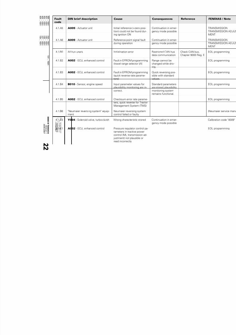
7/17/2019 Failure codes fendt 900 Vario 09 2007
http://slidepdf.com/reader/full/failure-codes-fendt-900-vario-09-2007 84/201
4 0 0 ..1 0 0 1 -
7 2 4 .
.1 0 0 1 -
7 3 1 ..1 0 0 1 -
4 0 1 ..1 0 0 1 -
7 2 5 ..1 0 0 1 -
4 0 2 ..1 0 0 1 -
7 2 6 ..1 0 0 1 -
4 0 3 ..1 0 0 1 -
7 2 7 ..1 0 0 1 -
4 0 4
1 0 0 1 -
7 2 9
1 0 0 1 -
0 0 0 0 BT 0 0 0 4 3 4
V er s i on1
2 0 / 0 9 / 2 0 0 7
2 2
4.1.A5 A009 - Actuator unit Initial reference (=zero posi-
tion) could not be found dur-
ing ignition ON
Continuation in emer-
gency mode possible
4.1.A6 A009 - Actuator unit Reference point signal fault
during operation
Continuation in emer-
gency mode possible
4.1.B0 All bus users Initialisation error Restricted CAN bus
data communication
Check CAN bus,
Chapter 9000 Reg
4.1.B2 A002 - ECU, enhanced control Fault in EPROM programming
(travel range selector I/II)
Range cannot be
changed while driv-
ing.
4.1.B3 A002 - ECU, enhanced control Fault in EPROM programming
(quick reverse rate parame-
ters)
Quick reversing pos-
sible with standard
values.
4.1.B4 B010 - Sensor, engine speed Input parameter values for
plausibility monitoring are in-
correct.
Standard parameters
are stored, plausibility
monitoring system
remains functional.
4.1.B5 A002 - ECU, enhanced control Checksum error rate parame-
ters, quick reverse for Tractor
Management System (TMS)
4.1.B6 "Neumaier reversing system" equip-
ment
Neumaier reversing system
control failed or faulty
4.1.E0 Y004 - Solenoid valve, turbo-clutch Wrong characteristic stored Continuation in emer-
gency mode possible
4.1.E1 A002 - ECU, enhanced control Pressure regulator control pa-
rameters in tractive power
control (ML transmission ad-
justment) not plausible or
read incorrectly
Faultcode
DIN brief description Cause Consequences Reference
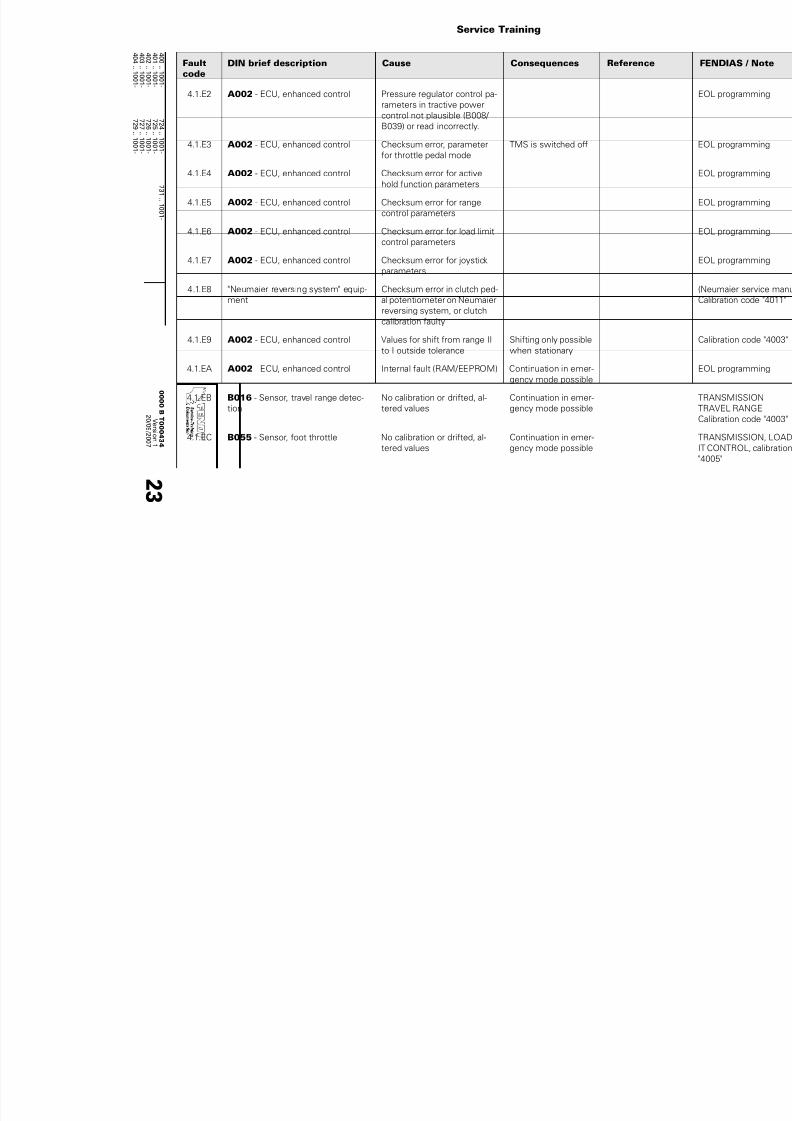
7/17/2019 Failure codes fendt 900 Vario 09 2007
http://slidepdf.com/reader/full/failure-codes-fendt-900-vario-09-2007 85/201
Service Training
4 0 0 ..1 0 0 1 -
7 2 4 .
.1 0 0 1 -
7 3 1 ..1 0 0 1 -
4 0 1 ..1 0 0 1 -
7 2 5 ..1 0 0 1 -
4 0 2 ..1 0 0 1 -
7 2 6 ..1 0 0 1 -
4 0 3 ..1 0 0 1 -
7 2 7 ..1 0 0 1 -
4 0 4
1 0 0 1 -
7 2 9
1 0 0 1 -
0 0 0 0 BT 0 0 0 4 3 4
V er s i on1
2 0 / 0 9 / 2 0 0 7
2 3
4.1.E2 A002 - ECU, enhanced control Pressure regulator control pa-
rameters in tractive power
control not plausible (B008/
B039) or read incorrectly.
4.1.E3 A002 - ECU, enhanced control Checksum error, parameter
for throttle pedal mode
TMS is switched off
4.1.E4 A002 - ECU, enhanced control Checksum error for active
hold function parameters
4.1.E5 A002 - ECU, enhanced control Checksum error for range
control parameters
4.1.E6 A002 - ECU, enhanced control Checksum error for load limit
control parameters
4.1.E7 A002 - ECU, enhanced control Checksum error for joystick
parameters
4.1.E8 "Neumaier reversing system" equip-
ment
Checksum error in clutch ped-
al potentiometer on Neumaier
reversing system, or clutch
calibration faulty
4.1.E9 A002 - ECU, enhanced control Values for shift from range II
to I outside tolerance
Shifting only possible
when stationary
4.1.EA A002 - ECU, enhanced control Internal fault (RAM/EEPROM) Continuation in emer-
gency mode possible
4.1.EB B016 - Sensor, travel range detec-
tion
No calibration or drifted, al-
tered values
Continuation in emer-
gency mode possible
4.1.EC B055 - Sensor, foot throttle No calibration or drifted, al-
tered values
Continuation in emer-
gency mode possible
Faultcode
DIN brief description Cause Consequences Reference

7/17/2019 Failure codes fendt 900 Vario 09 2007
http://slidepdf.com/reader/full/failure-codes-fendt-900-vario-09-2007 86/201
4 0 0 ..1 0 0 1 -
7 2 4 .
.1 0 0 1 -
7 3 1 ..1 0 0 1 -
4 0 1 ..1 0 0 1 -
7 2 5 ..1 0 0 1 -
4 0 2 ..1 0 0 1 -
7 2 6 ..1 0 0 1 -
4 0 3 ..1 0 0 1 -
7 2 7 ..1 0 0 1 -
4 0 4
1 0 0 1 -
7 2 9
1 0 0 1 -
0 0 0 0 BT 0 0 0 4 3 4
V er s i on1
2 0 / 0 9 / 2 0 0 7
2 4
4.1.ED B017 - Sensor, clutch pedal No calibration or drifted, al-
tered values
Continuation in emer-
gency mode possible
4.1.EE A002 - ECU, enhanced control No calibration or drifted, al-
tered values
Continuation in emer-
gency mode possible
4.1.EF A002 - ECU, enhanced control No calibration or drifted, al-
tered values
Continuation in emer-
gency mode possible
4.1.F0 A002 - ECU, enhanced control Incorrect checksum for trans-
mission calibration parame-
ters
Transmission calibra-
tion not possible
4.1.FF A002 - ECU, enhanced control Internal fault (RAM/EEPROM) Continuation in emer-
gency mode possible
5.1.00 A002 - ECU, enhanced control EEPROM checksum error
5.1.31 A004 - ECU, control panel
4WD 100% button
Faulty signal, button/A004 Other functions re-
main active
Wiring diagram
Sheet 33
5.1.32 A004 - ECU, control panel
Auto 4WD button
Faulty signal, button/A004 Other functions re-
main active
Wiring diagram
Sheet 33
5.1.33 Y009 - Solenoid valve, 4WD Actuation fault 4WD engages Wiring diagram
Sheet 33
5.1.34 B094 - Sensor, steering angle (4WD
differential lock)
Signal/switch fault 4WD/differential lock
auto system inopera-
ble
Wiring diagram
Sheet 33
5.1.35 B094 - Sensor, steering angle (4WD
differential lock)
Signal/switch fault 4WD/differential lock
auto system inopera-
ble
Wiring diagram
Sheet 33
5.1.51 A004 - ECU, control panel
Differential lock 100% button
Faulty signal, button/A004 Other functions re-
main active
Wiring diagram
Sheet 33
Faultcode
DIN brief description Cause Consequences Reference

7/17/2019 Failure codes fendt 900 Vario 09 2007
http://slidepdf.com/reader/full/failure-codes-fendt-900-vario-09-2007 87/201
Service Training
4 0 0 ..1 0 0 1 -
7 2 4 .
.1 0 0 1 -
7 3 1 ..1 0 0 1 -
4 0 1 ..1 0 0 1 -
7 2 5 ..1 0 0 1 -
4 0 2 ..1 0 0 1 -
7 2 6 ..1 0 0 1 -
4 0 3 ..1 0 0 1 -
7 2 7 ..1 0 0 1 -
4 0 4
1 0 0 1 -
7 2 9
1 0 0 1 -
0 0 0 0 BT 0 0 0 4 3 4
V er s i on1
2 0 / 0 9 / 2 0 0 7
2 5
5.1.52 A004 - ECU, control panel
Differential lock auto system button
Faulty signal, button/A004 Other functions re-
main active
Wiring diagram
Sheet 33
5.1.53 Y010 - Solenoid valve, differential
lock (rear)
Actuation fault Differential lock dis-
engages
Wiring diagram
Sheet 33
5.1.54 S006 - Switch, left brake Signal fault Differential lock auto
system no longer
available, TMS
switched off
Wiring diagram
Sheet 33
5.1.55 S005 - Switch, right brake Signal fault Differential lock auto
system no longer
available, TMS
switched off
Wiring diagram
Sheet 33
5.1.61 B003 - Sensor, front axle suspen-
sion position
Signal fault No further functionali-
ty, suspension re-
mains in last position.Further travel without
suspension possible
Wiring diagram
Sheet 31
Faulty 8.5 V supply A013 fuse 18
5.1.62 Y014 - Raise suspension solenoid
valve
12 V actuation faulty No further functionali-
ty, suspension re-
mains in last position.
Further travel without
suspension possible
Wiring diagram
Sheet 31
5.1.63 Y013 - Pressure cut-off valve, sus-
pension
12 V actuation faulty No further functionali-
ty, suspension re-
mains in last position.Further travel without
suspension possible
Wiring diagram
Sheet 31
5.1.64 A004 - ECU, control panel
"Suspension ON" button
Fault in signal from button to
A004
Suspension not oper-
ational. Further travel
without suspension
possible
Faultcode
DIN brief description Cause Consequences Reference

7/17/2019 Failure codes fendt 900 Vario 09 2007
http://slidepdf.com/reader/full/failure-codes-fendt-900-vario-09-2007 88/201
4 0 0 ..1 0 0 1 -
7 2 4 .
.1 0 0 1 -
7 3 1 ..1 0 0 1 -
4 0 1 ..1 0 0 1 -
7 2 5 ..1 0 0 1 -
4 0 2 ..1 0 0 1 -
7 2 6 ..1 0 0 1 -
4 0 3 ..1 0 0 1 -
7 2 7 ..1 0 0 1 -
4 0 4
1 0 0 1 -
7 2 9
1 0 0 1 -
0 0 0 0 BT 0 0 0 4 3 4
V er s i on1
2 0 / 0 9 / 2 0 0 7
2 6
5.1.65 A004 - ECU, control panel
"Suspension OFF/Lock" button
Fault in signal from button to
A004
Suspension not oper-
ational. Further travel
without suspension
possible
5.1.6E B003 - Sensor, front axle suspen-
sion position
Incorrect calibration Suspension not oper-
ational
5.1.8D A002 - ECU, enhanced control Checksum error old config.
data
Limited enhanced
control operation
5.1.8F A002 - ECU, enhanced control Checksum error old auto sys-
tem sequence data
Limited enhanced
control operation
5.1.91 A034 - Driving switch, CAN bus Signal fault from "Rear auto-
matic system ON/OFF" button
on joystick
Rear automatic sys-
tem not functioning
5.1.93 A034 - Driving switch, CAN bus Signal fault from "Front auto-
matic system ON/OFF" button
on joystick
Front automatic sys-
tem not functioning
5.1.95 A034 - Driving switch, CAN bus Signal fault from "Automatic
function STOP" button on joy-
stick
Automatic stop not
functioning
5.1.98 S025 - Switch, LS pump pressure
monitor
Minimum pressure not
reached
Valves may lock or
flow may be reduced
Wiring diagram
Sheet 26
See also Chapter
9000 Reg. E
5.1.99 S026
- Switch, steering pump flow
controller
Minimum flow not reached Control valve flow au-
tomatically reduced
to 20 l/min.
Wiring diagram
Sheet 26
See also Chapter
9000 Reg. E
Faultcode
DIN brief description Cause Consequences Reference

7/17/2019 Failure codes fendt 900 Vario 09 2007
http://slidepdf.com/reader/full/failure-codes-fendt-900-vario-09-2007 89/201
Service Training
4 0 0 ..1 0 0 1 -
7 2 4 .
.1 0 0 1 -
7 3 1 ..1 0 0 1 -
4 0 1 ..1 0 0 1 -
7 2 5 ..1 0 0 1 -
4 0 2 ..1 0 0 1 -
7 2 6 ..1 0 0 1 -
4 0 3 ..1 0 0 1 -
7 2 7 ..1 0 0 1 -
4 0 4
1 0 0 1 -
7 2 9
1 0 0 1 -
0 0 0 0 BT 0 0 0 4 3 4
V er s i on1
2 0 / 0 9 / 2 0 0 7
2 7
5.1.9A S026 - Switch, steering pump flow
controller
Switch faulty (no longer clos-
es/remains open even with-
out oil flow)
Plausibility error (in-
correct voltage value/
Ohm value)
Wiring diagram
Sheet 26
See also Chapter
9000 Reg. E
5.1.9B S025 - Switch, LS pump pressure
monitor
Faulty pressure switch No monitoring Wiring diagram
Sheet 26
See also Chapter
9000 Reg. E
5.1.9D B091 - Sensor, water in fuel Water in fuel Drain container Wiring diagram
Sheet 36
5.1.9E S034 - Switch, coolant level Level too low Engine damage! Wiring diagram
Sheet 24
5.1.9F S034 - Switch, coolant level Signal fault No further monitoring Wiring diagramSheet 24
5.1.B0 A002 - ECU, enhanced control CAN bus communication re-
stricted
5.1.FD A002 - ECU, enhanced control CAN3 component could not
be initialised
ISO bus may not be
fully functioning
5.1.FF A002 - ECU, enhanced control Internal fault (RAM/EEPROM)
6.1.01 A004 - ECU, control panel
Rear PTO button in cab ON/OFF
Signal fault, button/A004 PTO disengages Wiring diagram
Sheet 32
6.1.02 S020 - Switch (external), rear right
PTO
Signal fault PTO can be engaged
by pressing emergen-cy button in cab for 5
seconds
Wiring diagram
Sheet 32
6.1.03 S019 - Switch (external), rear left
PTO
Signal fault PTO can be engaged
by pressing emergen-
cy button in cab for 5
seconds
Wiring diagram
Sheet 32
Faultcode
DIN brief description Cause Consequences Reference

7/17/2019 Failure codes fendt 900 Vario 09 2007
http://slidepdf.com/reader/full/failure-codes-fendt-900-vario-09-2007 90/201
4 0 0 ..1 0 0 1 -
7 2 4 .
.1 0 0 1 -
7 3 1 ..1 0 0 1 -
4 0 1 ..1 0 0 1 -
7 2 5 ..1 0 0 1 -
4 0 2 ..1 0 0 1 -
7 2 6 ..1 0 0 1 -
4 0 3 ..1 0 0 1 -
7 2 7 ..1 0 0 1 -
4 0 4
1 0 0 1 -
7 2 9
1 0 0 1 -
0 0 0 0 BT 0 0 0 4 3 4
V er s i on1
2 0 / 0 9 / 2 0 0 7
2 8
6.1.04 Y008 - Solenoid valve, rear PTO
(clutch)
Actuation fault PTO disengages Wiring diagram
Sheet 32
6.1.05 B021 - Sensor, rear PTO speed
(clutch)
Signal fault PTO can be engaged
by pressing emergen-
cy button in cab for 5
seconds
Wiring diagram
Sheet 32
12 V supply fault A013 fuse 33
6.1.0A A004 - ECU, control panel "Active"
button (only NA version)
Button signal fault PTO cannot be en-
gaged
6.1.10 B020 - Sensor, rear PTO speed
(stub shaft)
Signal fault PTO can be engaged
by pressing emergen-
cy button in cab for 5
seconds
Wiring diagram
Sheet 32
12 V supply fault A013 fuse 32
6.1.11 A004 - ECU, control panel
Rear PTO auto mode button
Signal fault PTO disengages, au-
tomatic mode OFF
Wiring diagram
Sheet 32
6.1.15 A004 - ECU, control panel
Speed selector button NEUTRAL
Button signal fault PTO speed cannot be
modified or selected
Wiring diagram
Sheet 32
6.1.16 A004 - ECU, control panel
Speed selector button 540 rpm
Button signal fault PTO speed cannot be
modified or selected
Wiring diagram
Sheet 32
6.1.17 A004 - ECU, control panel
Speed selector button 750 rpm
Button signal fault PTO speed cannot be
modified or selected
Wiring diagram
Sheet 32
6.1.18 A004 - ECU, control panel
Speed selector key 1000 rpm
Button signal fault PTO speed cannot be
modified or selected
Wiring diagram
Sheet 32
6.1.1A Y026 - Solenoid valve, rear PTO,
stage I
Actuation fault PTO cannot be en-
gaged
Wiring diagram
Sheet 32
6.1.1B Y027 - Solenoid valve, rear PTO,
stage II
Actuation fault PTO cannot be en-
gaged
Wiring diagram
Sheet 32
Faultcode
DIN brief description Cause Consequences Reference

7/17/2019 Failure codes fendt 900 Vario 09 2007
http://slidepdf.com/reader/full/failure-codes-fendt-900-vario-09-2007 91/201
Service Training
4 0 0 ..1 0 0 1 -
7 2 4 .
.1 0 0 1 -
7 3 1 ..1 0 0 1 -
4 0 1 ..1 0 0 1 -
7 2 5 ..1 0 0 1 -
4 0 2 ..1 0 0 1 -
7 2 6 ..1 0 0 1 -
4 0 3 ..1 0 0 1 -
7 2 7 ..1 0 0 1 -
4 0 4
1 0 0 1 -
7 2 9
1 0 0 1 -
0 0 0 0 BT 0 0 0 4 3 4
V er s i on1
2 0 / 0 9 / 2 0 0 7
2 9
6.1.1C Y028 - Solenoid valve, rear PTO,
stage III
Actuation fault PTO cannot be en-
gaged
Wiring diagram
Sheet 32
6.1.41 A004 - ECU, control panelECU,
control panel Rear PTO ON/OFF but-
ton (in cab)
has been pressed for more
than 30 seconds, mechanical
or electrical fault in button
Speed selection
moves to "neutral", no
preselection possible
Wiring diagram
Sheet 32
6.1.42 S020 - Switch (external), rear right
PTO
has been pressed for more
than 30 seconds, mechanical
or electrical fault in button
No speed selection,
PTO cannot be en-
gaged
Wiring diagram
Sheet 32
6.1.43 S019 - Switch (external), rear left
PTO
has been pressed for more
than 30 seconds, mechanical
or electrical fault in button
No speed selection,
PTO cannot be en-
gaged
Wiring diagram
Sheet 32
6.1.45 S021 - Switch (external), raise front
power lift
Speed selection in neutral,
PTO clutch not engaged,
B021 shows speed, PTO
clutch disc package does notseparate, PTO brake not oper-
ational
elec. speed selection
remains possible,
press PTO clutch ON/
OFF button for atleast 5 seconds
(emergency mode)
Wiring diagram
Sheet 32
Speed is selected, PTO clutch
100% engaged, PTO clutch
speed deviates by more than
20% from engine speed. PTO
clutch disc package slipping.
elec. speed selection
remains possible,
press PTO clutch ON/
OFF button for at
least 5 seconds
(emergency mode)
PTO clutch speed is below
PTO stub speed
elec. speed selection
remains possible,
press PTO clutch ON/
OFF button for atleast 5 seconds
(emergency mode)
6.1.4A A004 - ECU, control panel
"Active" button (only NA version)
Button has been pressed for
more than 30 seconds, me-
chanical or electrical fault.
No PTO operation
possible
Faultcode
DIN brief description Cause Consequences Reference

7/17/2019 Failure codes fendt 900 Vario 09 2007
http://slidepdf.com/reader/full/failure-codes-fendt-900-vario-09-2007 92/201
4 0 0 ..1 0 0 1 -
7 2 4 .
.1 0 0 1 -
7 3 1 ..1 0 0 1 -
4 0 1 ..1 0 0 1 -
7 2 5 ..1 0 0 1 -
4 0 2 ..1 0 0 1 -
7 2 6 ..1 0 0 1 -
4 0 3 ..1 0 0 1 -
7 2 7 ..1 0 0 1 -
4 0 4
1 0 0 1 -
7 2 9
1 0 0 1 -
0 0 0 0 BT 0 0 0 4 3 4
V er s i on1
2 0 / 0 9 / 2 0 0 7
3 0
6.1.50 B020 - Sensor, rear PTO speed
(stub shaft)
PTO stub shaft speed > 1300
rpm, signal fault in Hall sensor
(B020 or B021)
elec. speed selection
remains possible,
press PTO clutch ON/
OFF button for at
least 5 seconds(emergency mode)
Wiring diagram
Sheet 32
Electric speed selection pos-
sible, press PTO clutch ON/
OFF button for at least 5 sec-
onds (emergency mode). In
the event of a faulty solenoid
valve, the corresponding
speed cannot be engaged.
elec. speed selection
remains possible,
press PTO clutch ON/
OFF button for at
least 5 seconds
(emergency mode)
Wiring diagram
Sheet 32
6.1.55 A004 - ECU, control panel
Speed selector button NEUTRAL
has been pressed for more
than 30 seconds, mechanical
or electrical fault in button
All speeds can be se-
lected and engage-
ment is possible.
Neutral button cannot
be selected.
Wiring diagram
Sheet 32
6.1.56 A004 - ECU, control panel
Speed selector button 540 rpm
has been pressed for more
than 30 seconds, mechanical
or electrical fault in button
Engagement possi-
ble, provided "540" is
selected. "1000" and
"750" selectable,
press PTO clutch but-
ton for longer than 5
secs. "540" not se-
lectable.
Wiring diagram
Sheet 32
6.1.57 A004 - ECU, control panel
Speed selector button 750 rpm
has been pressed for more
than 30 seconds, mechanicalor electrical fault in button
Engagement possible
provided "750" is se-lected. "1000" and
"540" selectable,
press PTO clutch but-
ton for longer than 5
secs. "750" not se-
lectable.
Wiring diagram
Sheet 32
Faultcode
DIN brief description Cause Consequences Reference

7/17/2019 Failure codes fendt 900 Vario 09 2007
http://slidepdf.com/reader/full/failure-codes-fendt-900-vario-09-2007 93/201
Service Training
4 0 0 ..1 0 0 1 -
7 2 4 .
.1 0 0 1 -
7 3 1 ..1 0 0 1 -
4 0 1 ..1 0 0 1 -
7 2 5 ..1 0 0 1 -
4 0 2 ..1 0 0 1 -
7 2 6 ..1 0 0 1 -
4 0 3 ..1 0 0 1 -
7 2 7 ..1 0 0 1 -
4 0 4
1 0 0 1 -
7 2 9
1 0 0 1 -
0 0 0 0 BT 0 0 0 4 3 4
V er s i on1
2 0 / 0 9 / 2 0 0 7
3 1
6.1.58 A004 - ECU, control panel
Speed selector key 1000 rpm
has been pressed for more
than 30 seconds, mechanical
or electrical fault in button
Engagement possible
provided "1000" is se-
lected. "750" and
"540" selectable,
press PTO clutch but-ton for longer than 5
secs. "1000" not se-
lectable.
Wiring diagram
Sheet 32
6.1.60 B020 - Sensor, rear PTO speed
(stub shaft)
B021 - Sensor, rear PTO speed
(clutch)
The actual speed of the PTO
stub (corrected by the trans-
mission rate) differs from the
specified speed of the PTO
clutch by more than 12%. So-
lenoid valve (Y026, Y027,
Y028) incorrectly wired or
stuck. Mechanical fault in
speed selector. Signal fault inHall sensor (B020, B021)
Electric speed selec-
tion remains possi-
ble, press "Engage
PTO" button for more
than 5 seconds
(emergency mode).
In case of a faulty so-
lenoid valve, corre-
sponding speedcannot be engaged.
Wiring diagram
Sheet 32
6.1.A1 A004 - ECU, control panel
Rear PTO "ON" button
Communication fault Wiring diagram
Sheet 32
6.1.AA A004 - ECU, control panel
"Active" button (only NA version)
Communication fault
6.1.B0 A004 - ECU, control panel CAN bus communication re-
stricted.
Rear PTO non-opera-
tional
6.1.B5 A004 - ECU, control panel
Speed selector button NEUTRAL
Communication fault
6.1.B6 A004 - ECU, control panelSpeed selector button 540 rpm
Communication fault
6.1.B7 A004 - ECU, control panel
Speed selector button 750 rpm
Communication fault
6.1.B8 A004 - ECU, control panel
Speed selector key 1000 rpm
Communication fault
Faultcode
DIN brief description Cause Consequences Reference

7/17/2019 Failure codes fendt 900 Vario 09 2007
http://slidepdf.com/reader/full/failure-codes-fendt-900-vario-09-2007 94/201
4 0 0 ..1 0 0 1 -
7 2 4 .
.1 0 0 1 -
7 3 1 ..1 0 0 1 -
4 0 1 ..1 0 0 1 -
7 2 5 ..1 0 0 1 -
4 0 2 ..1 0 0 1 -
7 2 6 ..1 0 0 1 -
4 0 3 ..1 0 0 1 -
7 2 7 ..1 0 0 1 -
4 0 4
1 0 0 1 -
7 2 9
1 0 0 1 -
0 0 0 0 BT 0 0 0 4 3 4
V er s i on1
2 0 / 0 9 / 2 0 0 7
3 2
6.1.E0 A002 - ECU, enhanced control Checksum error, parameter
current control for speed se-
lector
6.1.E1 A002 - ECU, enhanced control Checksum error, PTO parame-
terisation
7.1.01 A004 - ECU, control panel
Button, front PTO ON/OFF
Signal fault, Wiring diagram
Sheet 32
7.1.04 Y011 - Solenoid valve, front PTO
(clutch)
Actuation fault
7.1.05 B002 - Sensor, front PTO speed Signal fault Wiring diagram
Sheet 32
12 V supply fault A013 fuse 22
7.1.09 A004 - ECU, control panel
Front PTO "Automatic mode" button
Signal fault, Wiring diagram
Sheet 32
7.1.0A A004 - ECU, control panel
"Active" button (only NA version)
Signal fault,
7.1.41 A004 - ECU, control panel
Front PTO "ON" button
Plausibility error, button has
been pressed for more than
30 seconds
7.1.4A A004 - ECU, control panel
"Active" button (only NA version)
Plausibility error, button has
been pressed for more than
30 seconds
7.1.A1 A004 - ECU, control panel
Front PTO "ON" button
Communication fault
7.1.AA A004 - ECU, control panel
"Active" button (only NA version)
Communication fault
8.1.43 A004 - ECU, control panel
Automatic function (switching from
control panel to joystick)
Faulty button Switching not possi-
ble
Wiring diagram
Sheet 25
Faultcode
DIN brief description Cause Consequences Reference

7/17/2019 Failure codes fendt 900 Vario 09 2007
http://slidepdf.com/reader/full/failure-codes-fendt-900-vario-09-2007 95/201
Service Training
4 0 0 ..1 0 0 1 -
7 2 4 .
.1 0 0 1 -
7 3 1 ..1 0 0 1 -
4 0 1 ..1 0 0 1 -
7 2 5 ..1 0 0 1 -
4 0 2 ..1 0 0 1 -
7 2 6 ..1 0 0 1 -
4 0 3 ..1 0 0 1 -
7 2 7 ..1 0 0 1 -
4 0 4
1 0 0 1 -
7 2 9
1 0 0 1 -
0 0 0 0 BT 0 0 0 4 3 4
V er s i on1
2 0 / 0 9 / 2 0 0 7
3 3
8.3.11 A014 - ECU, EPC OBE E-box fault
(raise output)
Control barred and
locked
Wiring diagram
Sheet 25
8.3.12 A014 - ECU, EPC OBE E-box fault
(lower output)
Control barred and
locked
Wiring diagram
Sheet 25
8.3.14 S029 - Switch (external), raise rear
power lift, left
Signal line fault
Faulty button
Control barred and
locked
Wiring diagram
Sheet 25
8.3.15 S030 - Switch (external), lower rear
power lift, left
Signal line fault
Faulty button
Control barred and
locked
Wiring diagram
Sheet 25
8.3.16 A014 - ECU, EPC OBE Voltage < 1 V Control barred and
locked
Wiring diagram
Sheet 25
8.3.17 A014 - ECU, EPC OBE Supply voltage >18 V Control barred and
locked
Wiring diagram
Sheet 25
8.3.18 S027 - Switch (external), raise rear
power lift, right
Signal line fault, button faulty Control barred and
locked
Wiring diagram
Sheet 25
8.3.19 S028 - Switch (external), lower rear
power lift, right
Signal line fault, button faulty Control barred and
locked
Wiring diagram
Sheet 25
8.3.22 B030 - Sensor, rear power lift posi-
tion
Signal fault Control barred and
locked
Wiring diagram
Sheet 25
Supply of 10.0 V from A014
faulty
8.3.23 A004 - ECU, control panel
Specified value setting for rear pow-
er lift "Depth control"
Signal line fault Control barred and
locked
8.3.26 External position sensor for rear
power lift
Signal line fault
Sensor out of position
Sensor faulty
Control barred and
locked
Wiring diagram
Sheet 25
Faultcode
DIN brief description Cause Consequences Reference

7/17/2019 Failure codes fendt 900 Vario 09 2007
http://slidepdf.com/reader/full/failure-codes-fendt-900-vario-09-2007 96/201
4 0 0 ..1 0 0 1 -
7 2 4 .
.1 0 0 1 -
7 3 1 ..1 0 0 1 -
4 0 1 ..1 0 0 1 -
7 2 5 ..1 0 0 1 -
4 0 2 ..1 0 0 1 -
7 2 6 ..1 0 0 1 -
4 0 3 ..1 0 0 1 -
7 2 7 ..1 0 0 1 -
4 0 4
1 0 0 1 -
7 2 9
1 0 0 1 -
0 0 0 0 BT 0 0 0 4 3 4
V er s i on1
2 0 / 0 9 / 2 0 0 7
3 4
8.3.28 A004 - ECU, control panel Fault in rear EPC quick lift
switch
"Raise" and "Lower"
only possible via ex-
ternal buttons.
Wiring diagram
Sheet 25
8.3.31 B031 - Sensor, right draught sens-
ing pin
Signal line fault
Sensor faulty
Supply of 10.0 V from A014
faulty
Limited performance
during traction con-
trol
Wiring diagram
Sheet 25
8.3.32 B032 - Sensor, left draught sensing
pin
Signal line fault
Sensor faulty
Supply of 10.0 V from A014
faulty
Limited performance
during traction con-
trol
Wiring diagram
Sheet 25
8.3.33 A014 - ECU, EPC OBE
G001 - Battery 1 (12 VDC)
Battery voltage < 11.0 V Control barred and
locked
Wiring
diagram
Sheet 25
8.3.40 A004 - ECU, control panelRear power lift quick lift switch Switch faulty Raising and loweringonly via external con-
trols
Wiring diagramSheet 25
CAN (K bus) fault A004/A014
8.3.41 A004 - ECU, control panel
Rear power lift quick entry button
Faulty button Quick entry not func-
tioning
Wiring diagram
Sheet 25
CAN (K bus) fault A004/A014
8.3.42 A004 - ECU, control panel
Rear EPC, hitch function
Faulty button Hitch function not op-
erational
Wiring diagram
Sheet 25
CAN (K bus) fault A004/A014
8.3.43 A004 - ECU, control panel
Automatic function (switching from
control panel to joystick)
Faulty button Switching not possi-
ble
Wiring diagram
Sheet 25
CAN (K bus) fault A004/A014
Faultcode
DIN brief description Cause Consequences Reference

7/17/2019 Failure codes fendt 900 Vario 09 2007
http://slidepdf.com/reader/full/failure-codes-fendt-900-vario-09-2007 97/201
Service Training
4 0 0 ..1 0 0 1 -
7 2 4 .
.1 0 0 1 -
7 3 1 ..1 0 0 1 -
4 0 1 ..1 0 0 1 -
7 2 5 ..1 0 0 1 -
4 0 2 ..1 0 0 1 -
7 2 6 ..1 0 0 1 -
4 0 3 ..1 0 0 1 -
7 2 7 ..1 0 0 1 -
4 0 4
1 0 0 1 -
7 2 9
1 0 0 1 -
0 0 0 0 BT 0 0 0 4 3 4
V er s i on1
2 0 / 0 9 / 2 0 0 7
3 5
8.3.50 B031 - Sensor, right draught sens-
ing pin
Draught sensing pin is over-
loaded by stress on the lifting
gear in the upper range (90-
100% lift height) due to the
setting being too narrow.
Fault code will not be
stored
Wiring diagram
Sheet 25
8.3.51 B032 - Sensor, left draught sensing
pin
Draught sensing pin is over-
loaded by stress on the lifting
gear in the upper range (90-
100% lift height) due to the
setting being too narrow.
Fault code will not be
stored
Wiring diagram
Sheet 25
9.1.50 Y019 - Auxiliary control valve No signal from valve via bus
line.
No valve operation
available
Wiring diagram
Sheet 28
9.1.51 Y019 - Auxiliary control valve EEPROM inconsistent Valve moves into neu-
tral position
9.1.52 Y019 - Auxiliary control valve Supply voltage < 8 V Valve moves into neu-tral position
9.1.53 Y019 - Auxiliary control valve Supply voltage > 18 V Valve moves into neu-
tral position
9.1.54 Y019 - Auxiliary control valve Main piston travel too short
due to drop of control pres-
sure below 22 bar
Valve moves into neu-
tral position
Check control pre
sure M5, check di
phragm
accumulator, chec
RV7/FP
Hydraulic oil temperature too
low
9.1.55 Y019 - Auxiliary control valve Overvoltage (> 45 V) Valve moves into neu-
tral position
9.1.56 Y019 - Auxiliary control valve Output fault at control valve
magnet
Valve moves into neu-
tral position
9.1.57 Y019 - Auxiliary control valve Internal position sensor fault Valve moves into neu-
tral position
Faultcode
DIN brief description Cause Consequences Reference

7/17/2019 Failure codes fendt 900 Vario 09 2007
http://slidepdf.com/reader/full/failure-codes-fendt-900-vario-09-2007 98/201
4 0 0 ..1 0 0 1 -
7 2 4 .
.1 0 0 1 -
7 3 1 ..1 0 0 1 -
4 0 1 ..1 0 0 1 -
7 2 5 ..1 0 0 1 -
4 0 2 ..1 0 0 1 -
7 2 6 ..1 0 0 1 -
4 0 3 ..1 0 0 1 -
7 2 7 ..1 0 0 1 -
4 0 4
1 0 0 1 -
7 2 9
1 0 0 1 -
0 0 0 0 BT 0 0 0 4 3 4
V er s i on1
2 0 / 0 9 / 2 0 0 7
3 6
9.1.58 Y019 - Auxiliary control valve Main piston cannot return to
neutral position due to oil con-
tamination.
Manual actuation,
actuator must not
have any play, act
tor must move to t
centre position byself
9.1.59 Y019 - Auxiliary control valve Main piston cannot return to
neutral position when
switched on due to oil con-
tamination.
9.1.5A Y019 - Auxiliary control valve Main piston deflected too far Valve moves into neu-
tral position
9.1.5B Y019 - Auxiliary control valve Floating position is not
reached
Valve moves into neu-
tral position
9.1.5C Y019 - Auxiliary control valve Floating position has been de-flected manually No consequences
9.1.5F Y019 - Auxiliary control valve Specified value message
missing
Valve moves into neu-
tral position
Configuration message miss-
ing
Specified value message is
not plausible
Configuration message is not
plausible
Potentiometer or PWM fault
9.1.A0 A002 - ECU, enhanced control EEPROM fault while saving Set values (enhanced
controls) not stored.
9.1.A1 A002 - ECU, enhanced control EEPROM fault while loading Set values (enhanced
controls) cannot be
read.
Faultcode
DIN brief description Cause Consequences Reference

7/17/2019 Failure codes fendt 900 Vario 09 2007
http://slidepdf.com/reader/full/failure-codes-fendt-900-vario-09-2007 99/201
Service Training
4 0 0 ..1 0 0 1 -
7 2 4 .
.1 0 0 1 -
7 3 1 ..1 0 0 1 -
4 0 1 ..1 0 0 1 -
7 2 5 ..1 0 0 1 -
4 0 2 ..1 0 0 1 -
7 2 6 ..1 0 0 1 -
4 0 3 ..1 0 0 1 -
7 2 7 ..1 0 0 1 -
4 0 4
1 0 0 1 -
7 2 9
1 0 0 1 -
0 0 0 0 BT 0 0 0 4 3 4
V er s i on1
2 0 / 0 9 / 2 0 0 7
3 7
9.1.B0 B040 - Sensor, front power lift posi-
tion
Not calibrated No position control
available
9.1.B1 B040 - Sensor, front power lift posi-
tion
Signal fault No position control
available
Wiring diagram
Sheet 27
8.5 V supply fault A013 fuse 11
9.1.B2 A004 - ECU, control panel
Depth control specified value poten-
tiometer
Not calibrated Specified value can-
not be set
9.1.B3 A004 - ECU, control panel
Depth control specified value poten-
tiometer
Signal fault, Specified value can-
not be set
9.1.C0 A004 - ECU, control panel
Control panel
Not available or bus not con-
nected
9.1.C1 A004 - ECU, control panelAutomatic system (switching from
control panel/joystick)
Faulty button
9.1.C2 A004 - ECU, control panel
Valve locking
Faulty button
9.1.C3 A004 - ECU, control panel
Floating position
Faulty button
9.1.C4 A004 - ECU, control panel
"Raise" quick lift switch
Faulty button
9.1.C5 A004 - ECU, control panel
"Lower" quick lift switch
Faulty button
9.1.C6
9.1.C7
9.1.C8
9.1.C9
9.1.CA
A004 - ECU, control panel CAN bus faulty Unspecified malfunc-
tions
Faultcode
DIN brief description Cause Consequences Reference

7/17/2019 Failure codes fendt 900 Vario 09 2007
http://slidepdf.com/reader/full/failure-codes-fendt-900-vario-09-2007 100/201
4 0 0 ..1 0 0 1 -
7 2 4 .
.1 0 0 1 -
7 3 1 ..1 0 0 1 -
4 0 1 ..1 0 0 1 -
7 2 5 ..1 0 0 1 -
4 0 2 ..1 0 0 1 -
7 2 6 ..1 0 0 1 -
4 0 3 ..1 0 0 1 -
7 2 7 ..1 0 0 1 -
4 0 4
1 0 0 1 -
7 2 9
1 0 0 1 -
0 0 0 0 BT 0 0 0 4 3 4
V er s i on1
2 0 / 0 9 / 2 0 0 7
3 8
9.1.D0 S021 - Switch (external), raise front
power lift
Faulty button Function non-opera-
ble
Wiring diagram
Sheet 27
9.1.D1 S022 - Switch (external), lower
front power lift
Faulty button Function non-opera-
ble
Wiring diagram
Sheet 27
9.1.D2 S021 - Switch (external), raise front
power liftS022 - Switch (external),
lower front power lift
Double button operation (but-
ton possibly stuck)
Wiring diagram
Sheet 27
A.1.10 Y015 - Auxiliary control valve No signal from valve to valve
bus
No valve operation
available
Wiring diagram
Sheet 28
A.1.11 Y015 - Auxiliary control valve EEPROM inconsistent Valve moves into neu-
tral position
A.1.12 Y015 - Auxiliary control valve Valve moves into neu-
tral position
A.1.13 Y015 - Auxiliary control valve Supply voltage > 18 V Valve moves into neu-tral position
A.1.14 Y015 - Auxiliary control valve Main piston travel too short
due to drop of control pres-
sure below 22 bar
Valve moves into neu-
tral position
Check control pre
sure M5, check di
phragm
accumulator, chec
RV7/FP
Hydraulic oil temperature too
low
A.1.15 Y015 - Auxiliary control valve Overvoltage (> 45 V) Valve moves into neu-
tral position
A.1.16 Y015 - Auxiliary control valve Output fault at control valve
magnet
Valve moves into neu-
tral position
A.1.17 Y015 - Auxiliary control valve Internal position sensor fault Valve moves into neu-
tral position
Faultcode
DIN brief description Cause Consequences Reference

7/17/2019 Failure codes fendt 900 Vario 09 2007
http://slidepdf.com/reader/full/failure-codes-fendt-900-vario-09-2007 101/201
Service Training
4 0 0 ..1 0 0 1 -
7 2 4 .
.1 0 0 1 -
7 3 1 ..1 0 0 1 -
4 0 1 ..1 0 0 1 -
7 2 5 ..1 0 0 1 -
4 0 2 ..1 0 0 1 -
7 2 6 ..1 0 0 1 -
4 0 3 ..1 0 0 1 -
7 2 7 ..1 0 0 1 -
4 0 4
1 0 0 1 -
7 2 9
1 0 0 1 -
0 0 0 0 BT 0 0 0 4 3 4
V er s i on1
2 0 / 0 9 / 2 0 0 7
3 9
A.1.18 Y015 - Auxiliary control valve Main piston cannot return to
neutral position due to oil con-
tamination.
Valve may cause un-
controlled functions,
DANGER!
Manual actuation,
actuator must not
have any play, act
tor must move to t
centre position byself
A.1.19 Y015 - Auxiliary control valve Main piston cannot return to
neutral position when
switched on due to oil con-
tamination.
A.1.1A Y015 - Auxiliary control valve Main piston deflected too far Valve moves into neu-
tral position
A.1.1B Y015 - Auxiliary control valve Floating position is not
reached
Valve moves into neu-
tral position
A.1.1C Y015 - Auxiliary control valve Floating position has been de-flected manually without result
A.1.1F Y015 - Auxiliary control valve Specified value message is
missing or not plausible
Valve moves into neu-
tral position
Configuration message is
missing or not plausible
Potentiometer or PWM fault
A.1.20 Y016 - Auxiliary control valve No signal from valve to valve
bus
No valve operation
available
Wiring diagram
Sheet 28
A.1.21 Y016 - Auxiliary control valve EEPROM inconsistent Valve moves into neu-
tral position
A.1.22 Y016 - Auxiliary control valve Valve moves into neu-
tral position
A.1.23 Y016 - Auxiliary control valve Supply voltage > 18 V Valve moves into neu-
tral position
Faultcode
DIN brief description Cause Consequences Reference

7/17/2019 Failure codes fendt 900 Vario 09 2007
http://slidepdf.com/reader/full/failure-codes-fendt-900-vario-09-2007 102/201
4 0 0 ..1 0 0 1 -
7 2 4 .
.1 0 0 1 -
7 3 1 ..1 0 0 1 -
4 0 1 ..1 0 0 1 -
7 2 5 ..1 0 0 1 -
4 0 2 ..1 0 0 1 -
7 2 6 ..1 0 0 1 -
4 0 3 ..1 0 0 1 -
7 2 7 ..1 0 0 1 -
4 0 4
1 0 0 1 -
7 2 9
1 0 0 1 -
0 0 0 0 BT 0 0 0 4 3 4
V er s i on1
2 0 / 0 9 / 2 0 0 7
4 0
A.1.24 Y016 - Auxiliary control valve Main piston travel too short
due to drop of control pres-
sure below 22 bar
Valve moves into neu-
tral position
Check control pre
sure M5, check di
phragm
accumulator, chec
RV7/FP
Hydraulic oil temperature too
low
A.1.25 Y016 - Auxiliary control valve Overvoltage (> 45 V) Valve moves into neu-
tral position
A.1.26 Y016 - Auxiliary control valve Output fault at control valve
magnet
Valve moves into neu-
tral position
A.1.27 Y016 - Auxiliary control valve Internal position sensor fault Valve moves into neu-
tral position
A.1.28 Y016 - Auxiliary control valve Main piston cannot return to
neutral position due to oil con-
tamination.
Valve may cause un-
controlled functions,
DANGER!
Manual actuation,
actuator must not
have any play, act
tor must move to t
centre position by
self
A.1.29 Y016 - Auxiliary control valve Main piston cannot return to
neutral position when
switched on due to oil con-
tamination.
A.1.2A Y016 - Auxiliary control valve Main piston deflected too far Valve moves into neu-
tral position
A.1.2B Y016 - Auxiliary control valve Floating position is not
reached
Valve moves into neu-
tral position
A.1.2C Y016 - Auxiliary control valve Floating position has been de-
flected manually
without result
A.1.2F Y016 - Auxiliary control valve Specified value message is
missing or not plausible
Valve moves into neu-
tral position
Faultcode
DIN brief description Cause Consequences Reference

7/17/2019 Failure codes fendt 900 Vario 09 2007
http://slidepdf.com/reader/full/failure-codes-fendt-900-vario-09-2007 103/201
Service Training
4 0 0 ..1 0 0 1 -
7 2 4 .
.1 0 0 1 -
7 3 1 ..1 0 0 1 -
4 0 1 ..1 0 0 1 -
7 2 5 ..1 0 0 1 -
4 0 2 ..1 0 0 1 -
7 2 6 ..1 0 0 1 -
4 0 3 ..1 0 0 1 -
7 2 7 ..1 0 0 1 -
4 0 4
1 0 0 1 -
7 2 9
1 0 0 1 -
0 0 0 0 BT 0 0 0 4 3 4
V er s i on1
2 0 / 0 9 / 2 0 0 7
4 1
Configuration message is
missing or not plausible
Potentiometer or PWM fault
A.1.30 Y017 - Auxiliary control valve No signal from valve to valvebus
No valve operationavailable
Wiring diagramSheet 28
A.1.31 Y017 - Auxiliary control valve EEPROM inconsistent Valve moves into neu-
tral position
A.1.32 Y017 - Auxiliary control valve Valve moves into neu-
tral position
A.1.33 Y017 - Auxiliary control valve Supply voltage > 18 V Valve moves into neu-
tral position
A.1.34 Y017 - Auxiliary control valve Main piston travel too short
due to drop of control pres-
sure below 22 bar
Valve moves into neu-
tral position
Check control pre
sure M5, check di
phragmaccumulator, chec
RV7/FP
Hydraulic oil temperature too
low
A.1.35 Y017 - Auxiliary control valve Overvoltage (> 45 V) Valve moves into neu-
tral position
A.1.36 Y017 - Auxiliary control valve Output fault at control valve
magnet
Valve moves into neu-
tral position
A.1.37 Y017 - Auxiliary control valve Internal position sensor fault Valve moves into neu-
tral position
A.1.38 Y017 - Auxiliary control valve Main piston cannot return to
neutral position due to oil con-
tamination.
Valve may cause un-
controlled functions,
DANGER!
Manual actuation,
actuator must not
have any play, act
tor must move to t
centre position by
self
Faultcode
DIN brief description Cause Consequences Reference

7/17/2019 Failure codes fendt 900 Vario 09 2007
http://slidepdf.com/reader/full/failure-codes-fendt-900-vario-09-2007 104/201
4 0 0 ..1 0 0 1 -
7 2 4 .
.1 0 0 1 -
7 3 1 ..1 0 0 1 -
4 0 1 ..1 0 0 1 -
7 2 5 ..1 0 0 1 -
4 0 2 ..1 0 0 1 -
7 2 6 ..1 0 0 1 -
4 0 3 ..1 0 0 1 -
7 2 7 ..1 0 0 1 -
4 0 4
1 0 0 1 -
7 2 9
1 0 0 1 -
0 0 0 0 BT 0 0 0 4 3 4
V er s i on1
2 0 / 0 9 / 2 0 0 7
4 2
A.1.39 Y017 - Auxiliary control valve Main piston cannot return to
neutral position when
switched on due to oil con-
tamination.
A.1.3A Y017 - Auxiliary control valve Main piston deflected too far Valve moves into neu-
tral position
A.1.3B Y017 - Auxiliary control valve Floating position is not
reached
Valve moves into neu-
tral position
A.1.3C Y017 - Auxiliary control valve Floating position has been de-
flected manually
without result
A.1.3F Y017 - Auxiliary control valve Specified value message is
missing or not plausible
Valve moves into neu-
tral position
Configuration message is
missing or not plausible
Potentiometer or PWM fault
A.1.40 Y018 - Auxiliary control valve No signal from valve to valve
bus
No valve operation
available
Wiring diagram
Sheet 28
A.1.41 Y018 - Auxiliary control valve EEPROM inconsistent Valve moves into neu-
tral position
A.1.42 Y018 - Auxiliary control valve Valve moves into neu-
tral position
A.1.43 Y018 - Auxiliary control valve Supply voltage > 18 V Valve moves into neu-
tral position
A.1.44 Y018 - Auxiliary control valve Main piston travel too short
due to drop of control pres-
sure below 22 bar
Valve moves into neu-
tral position
Check control pre
sure M5, check di
phragm
accumulator, chec
RV7/FP
Faultcode
DIN brief description Cause Consequences Reference

7/17/2019 Failure codes fendt 900 Vario 09 2007
http://slidepdf.com/reader/full/failure-codes-fendt-900-vario-09-2007 105/201
Service Training
4 0 0 ..1 0 0 1 -
7 2 4 .
.1 0 0 1 -
7 3 1 ..1 0 0 1 -
4 0 1 ..1 0 0 1 -
7 2 5 ..1 0 0 1 -
4 0 2 ..1 0 0 1 -
7 2 6 ..1 0 0 1 -
4 0 3 ..1 0 0 1 -
7 2 7 ..1 0 0 1 -
4 0 4
1 0 0 1 -
7 2 9
1 0 0 1 -
0 0 0 0 BT 0 0 0 4 3 4
V er s i on1
2 0 / 0 9 / 2 0 0 7
4 3
Hydraulic oil temperature too
low
A.1.45 Y018 - Auxiliary control valve Overvoltage (> 45 V) Valve moves into neu-
tral position
A.1.46 Y018 - Auxiliary control valve Output fault at control valve
magnet
Valve moves into neu-
tral position
A.1.47 Y018 - Auxiliary control valve Internal position sensor fault Valve moves into neu-
tral position
A.1.48 Y018 - Auxiliary control valve Main piston cannot return to
neutral position due to oil con-
tamination.
Valve may cause un-
controlled functions,
DANGER!
Manual actuation,
actuator must not
have any play, act
tor must move to t
centre position by
self
A.1.49 Y018 - Auxiliary control valve Main piston cannot return to
neutral position when
switched on due to oil con-
tamination.
A.1.4A Y018 - Auxiliary control valve Main piston deflected too far Valve moves into neu-
tral position
A.1.4B Y018 - Auxiliary control valve Floating position is not
reached
Valve moves into neu-
tral position
A.1.4C Y018 - Auxiliary control valve Floating position has been de-
flected manually
without result
A.1.4F Y018 - Auxiliary control valve Specified value message ismissing or not plausible
Valve moves into neu-tral position
Configuration message is
missing or not plausible
Potentiometer or PWM fault
Faultcode
DIN brief description Cause Consequences Reference

7/17/2019 Failure codes fendt 900 Vario 09 2007
http://slidepdf.com/reader/full/failure-codes-fendt-900-vario-09-2007 106/201
4 0 0 ..1 0 0 1 -
7 2 4 .
.1 0 0 1 -
7 3 1 ..1 0 0 1 -
4 0 1 ..1 0 0 1 -
7 2 5 ..1 0 0 1 -
4 0 2 ..1 0 0 1 -
7 2 6 ..1 0 0 1 -
4 0 3 ..1 0 0 1 -
7 2 7 ..1 0 0 1 -
4 0 4
1 0 0 1 -
7 2 9
1 0 0 1 -
0 0 0 0 BT 0 0 0 4 3 4
V er s i on1
2 0 / 0 9 / 2 0 0 7
4 4
A.1.50 S053 - Switch, driver seat Seat not "loaded" when steer-
ing is activated
A.1.51 B094 - Sensor, steering angle (4WD
differential lock)
Despite the steering valve be-
ing open, the steering angle
sensor produces no fresh val-
ues within 1 second
Steering angle se
sor mechanical fau
no hydraulic oil in t
steering valve
A.1.52 B094 - Sensor, steering angle (4WD
differential lock)
Invalid calibration values for
steering angle sensor in EEP-
ROM
A.1.53 A058 - Top Dock (Autoguide) Top Dock bus fault No signal from Top
Dock to transmission
bus
Top Dock voltage
supply
A.1.55 A057 - ECU, steering controller (Au-
toguide)
An EEPROM description fault
has occurred
A.1.56 A057 - ECU, steering controller (Au-
toguide)
An EEPROM reading fault has
occurred
A.1.57 A057 - ECU, steering controller (Au-
toguide)
The EEPROM contains invalid
data
A.1.5A A057 - ECU, steering controller (Au-
toguide)
Invalid EEPROM parameters
for the steering control regula-
tor
Invalid data set
A.1.5B A057 - ECU, steering controller (Au-
toguide)
Invalid EEPROM parameters
for the steering control regula-
tor
Invalid data set
A.1.5C A057 - ECU, steering controller (Au-
toguide)
Invalid EEPROM parameters
for the steering control regula-
tor
Invalid data set
Faultcode
DIN brief description Cause Consequences Reference

7/17/2019 Failure codes fendt 900 Vario 09 2007
http://slidepdf.com/reader/full/failure-codes-fendt-900-vario-09-2007 107/201
Service Training
4 0 0 ..1 0 0 1 -
7 2 4 .
.1 0 0 1 -
7 3 1 ..1 0 0 1 -
4 0 1 ..1 0 0 1 -
7 2 5 ..1 0 0 1 -
4 0 2 ..1 0 0 1 -
7 2 6 ..1 0 0 1 -
4 0 3 ..1 0 0 1 -
7 2 7 ..1 0 0 1 -
4 0 4
1 0 0 1 -
7 2 9
1 0 0 1 -
0 0 0 0 BT 0 0 0 4 3 4
V er s i on1
2 0 / 0 9 / 2 0 0 7
4 5
A.1.5D A057 - ECU, steering controller (Au-
toguide)
Invalid frequency for steering
control regulator, entered as
EEPROM parameters
Invalid data set
A.1.5E A057 - ECU, steering controller (Au-
toguide)
Supply voltage < 10.1 VDC Wiring diagram
Sheet 39
A.1.5F A057 - ECU, steering controller (Au-
toguide)
Internal fault
A.1.60 Fault only possible in calibration
mode
Autoguide is active and cali-
bration of the steering valve is
started at the same time or
calibration is restarted al-
though it has not yet finished
Successful calibration
indicated by OK
Restart calibration
A.1.61 Fault only possible in calibration
mode
The value of the steering an-
gle sensor has not changed al-
though the valve is 100%open
Steering angle se
sor mechanical fau
no hydraulic oil in tsteering valve
A.1.62 Fault only possible in calibration
mode
Although the steering should
be moved to the left during
calibration, a steering move-
ment to the right was detect-
ed.
Repeat calibration,
paying attention to
the sideways free-
dom of movement of
the front wheels
A.1.63 Fault only possible in calibration
mode
The steering wheel was
moved during calibration
Repeat calibration
A.1.64 Y087 - Steering valve block, Au-
toguide
The steering valve has not yet
been calibrated
A.1.65 Y087 - Steering valve block, Au-
toguide
Unidentified fault in the steer-
ing valve
Check the steering
valve
A.1.66 Y087 - Steering valve block, Au-
toguide
Wiring of the position sensor
in the steering valve either
broken or short-circuited
Check the steering
valve, or replace
steering head
Faultcode
DIN brief description Cause Consequences Reference

7/17/2019 Failure codes fendt 900 Vario 09 2007
http://slidepdf.com/reader/full/failure-codes-fendt-900-vario-09-2007 108/201
4 0 0 ..1 0 0 1 -
7 2 4 .
.1 0 0 1 -
7 3 1 ..1 0 0 1 -
4 0 1 ..1 0 0 1 -
7 2 5 ..1 0 0 1 -
4 0 2 ..1 0 0 1 -
7 2 6 ..1 0 0 1 -
4 0 3 ..1 0 0 1 -
7 2 7 ..1 0 0 1 -
4 0 4
1 0 0 1 -
7 2 9
1 0 0 1 -
0 0 0 0 BT 0 0 0 4 3 4
V er s i on1
2 0 / 0 9 / 2 0 0 7
4 6
A.1.67 Y087 - Steering valve block, Au-
toguide
Steering valve monitoring er-
ror message
A.1.68 Y087 - Steering valve block, Au-
toguide
Steering valve status mes-
sage not received within the
specified time
CAN bus fault in the
transmission bus
Wiring diagram
Sheet 39
A.1.69 Y087 - Steering valve block, Au-
toguide
Supply voltage > 32 V Wiring diagram
Sheet 39
A.1.6A Y087 - Steering valve block, Au-
toguide
Supply voltage < 10 V Wiring diagram
Sheet 39
A.1.6B Y087 - Steering valve block, Au-
toguide
Steering actuator cannot
reach neutral
(during operation)
Mechanical fault on
steering actuator or
position sensor
A.1.6C Y087 - Steering valve block, Au-
toguide
Actuator not in neutral during
"RUNUP"
(same at switch on)
Mechanical fault on
steering actuator or
position sensor
A.1.6D Y087 - Steering valve block, Au-
toguide
Actuator position greater than
reference position
Mechanical fault on
steering actuator or
position sensor
A.1.70 B094 - Sensor, steering angle (4WD
differential lock)
Break in steering sensor sig-
nal line
Check signal line Wiring diagram
Sheet 33 / 39
A.1.71 A057 - ECU, steering controller
(Autoguide)Y087 - Steering valve
block, Autoguide
Break in the steering valve
electrical supply line
Check the steering
valve electrical supply
line
Wiring diagram
Sheet 38 / 39
A.1.72 Y099 - Solenoid valve, pilot pres-
sure (Autoguide)
Break in the electrical supply
line to the pilot pressure sole-noid valve
Wiring diagram
Sheet 39
A.1.74 S088 - Switch, Autoguide pressure Break in the pressure switch
signal line
Wiring diagram
Sheet 39
A.1.80 B094 - Sensor, steering angle (4WD
differential lock)
Short circuit in steering angle
sensor supply
Wiring diagram
Sheet 33 / 39
Faultcode
DIN brief description Cause Consequences Reference

7/17/2019 Failure codes fendt 900 Vario 09 2007
http://slidepdf.com/reader/full/failure-codes-fendt-900-vario-09-2007 109/201
Service Training
4 0 0 ..1 0 0 1 -
7 2 4 .
.1 0 0 1 -
7 3 1 ..1 0 0 1 -
4 0 1 ..1 0 0 1 -
7 2 5 ..1 0 0 1 -
4 0 2 ..1 0 0 1 -
7 2 6 ..1 0 0 1 -
4 0 3 ..1 0 0 1 -
7 2 7 ..1 0 0 1 -
4 0 4
1 0 0 1 -
7 2 9
1 0 0 1 -
0 0 0 0 BT 0 0 0 4 3 4
V er s i on1
2 0 / 0 9 / 2 0 0 7
4 7
A.1.82 Y099 - Solenoid valve, pilot pres-
sure (Autoguide)
Short circuit in supply line or
pilot pressure solenoid valve
wiring break
Wiring diagram
Sheet 39
A.1.84 S088 - Switch, Autoguide pressure Short-circuit in the supply line
of the pressure switch signal
line
Wiring diagram
Sheet 39
A.1.85 B094 - Sensor, steering angle (4WD
differential lock)
S088 - Switch, Autoguide pressure
Short circuit in the voltage
supply for the steering angle
sensor and pressure switch
Wiring diagram
Sheet 39
A.1.90 B094 - Sensor, steering angle (4WD
differential lock)
Short circuit in steering angle
sensor earth
Wiring diagram
Sheet 33 / 39
A.1.91 A057 - ECU, steering controller (Au-
toguide)
Y087 - Steering valve block, Au-
toguide
Short circuit in steering valve
block voltage supply earth
Wiring diagram
Sheet 39
A.1.92 Y099 - Solenoid valve, pilot pres-
sure (Autoguide)
Short circuit in pilot pressure
solenoid valve earth
Wiring diagram
Sheet 39
A.1.94 S088 - Switch, Autoguide pressure Short circuit in pressure
switch signal line earth
Wiring diagram
Sheet 39
A.1.95 A057 - ECU, steering controller (Au-
toguide)
B094 - Sensor, steering angle (4WD
differential lock)
S088 - Switch, Autoguide pressure
Short circuit in earth of volt-
age supply for steering angle
sensor and pressure switch
Wiring diagram
Sheet 39
A.1.A0 A002
- ECU, enhanced control EEPROM fault while saving
A.1.A1 A002 - ECU, enhanced control EEPROM fault while loading
A.1.A2 More valves connected than
registered via EOL program-
ming
Not all valves can be
actuated
Faultcode
DIN brief description Cause Consequences Reference

7/17/2019 Failure codes fendt 900 Vario 09 2007
http://slidepdf.com/reader/full/failure-codes-fendt-900-vario-09-2007 110/201
4 0 0 ..1 0 0 1 -
7 2 4 .
.1 0 0 1 -
7 3 1 ..1 0 0 1 -
4 0 1 ..1 0 0 1 -
7 2 5 ..1 0 0 1 -
4 0 2 ..1 0 0 1 -
7 2 6 ..1 0 0 1 -
4 0 3 ..1 0 0 1 -
7 2 7 ..1 0 0 1 -
4 0 4
1 0 0 1 -
7 2 9
1 0 0 1 -
0 0 0 0 BT 0 0 0 4 3 4
V er s i on1
2 0 / 0 9 / 2 0 0 7
4 8
A.1.B0 A034 - Driving switch, CAN bus
Crossgate lever
Not calibrated Valves cannot be op-
erated
A.1.B1 A034 - Driving switch, CAN bus
Crossgate lever
X axis signal fault Valves cannot be op-
erated
Wiring diagram
Sheet 26
A.1.B2 A034 - Driving switch, CAN bus
Crossgate lever
Y axis signal fault Valves cannot be op-
erated
Wiring diagram
Sheet 26
A.1.B3 A034 - Driving switch, CAN bus
Crossgate lever
X and Y axis signal fault;
crossgate lever missing
Valves cannot be op-
erated
Wiring diagram
Sheet 26
A.1.B4 A034 - Driving switch, CAN bus
Crossgate lever
Zero position signals of X and
Y axes are not identical to the
"centre position" signal (=plau-
sibility check)
Valves cannot be op-
erated
Wiring diagram
Sheet 26
A.1.B5 A034 - Driving switch, CAN bus
Crossgate lever
"Centre position" signal fault Valves cannot be op-
erated
Wiring diagram
Sheet 26
A.1.C0 A004 - ECU, control panel Not available or bus not con-
nected
A.1.C1 A004 - ECU, control panel Automatic system (switching
from control panel/joystick)
button faulty
A.1.C2 A004 - ECU, control panel Valve locking button faulty
A.1.C3 A004 - ECU, control panel Floating position button faulty No floating position
A.1.C4 A004 - ECU, control panel Time function button faulty No time function
A.1.C5 A004 - ECU, control panel Switching function button
faulty
Faultcode
DIN brief description Cause Consequences Reference

7/17/2019 Failure codes fendt 900 Vario 09 2007
http://slidepdf.com/reader/full/failure-codes-fendt-900-vario-09-2007 111/201
Service Training
4 0 0 ..1 0 0 1 -
7 2 4 .
.1 0 0 1 -
7 3 1 ..1 0 0 1 -
4 0 1 ..1 0 0 1 -
7 2 5 ..1 0 0 1 -
4 0 2 ..1 0 0 1 -
7 2 6 ..1 0 0 1 -
4 0 3 ..1 0 0 1 -
7 2 7 ..1 0 0 1 -
4 0 4
1 0 0 1 -
7 2 9
1 0 0 1 -
0 0 0 0 BT 0 0 0 4 3 4
V er s i on1
2 0 / 0 9 / 2 0 0 7
4 9
A.1.C6
A.1.C7
A.1.C8
A.1.C9
A.1.CA
A004 - ECU, control panel CAN bus faulty Unspecified malfunc-
tions
A.1.CB A034 - Driving switch, CAN bus CAN joystick not available.
(CAN bus faulty)
Valves cannot be op-
erated
A.1.CC A002 - ECU, enhanced control
A034 - Driving switch, CAN bus
ECU and joystick CAN com-
munication faulty.
Restricted valve oper-
ation
A.1.D1 A034 - Driving switch, CAN bus Control valve 3 Raise/Lower
button faulty
No valve operation
available
A.1.D3 A034 - Driving switch, CAN bus Control valve 4 Raise/Lower
button faulty
No valve operation
available
A.1.D4 S023 - Switch (external), lock front
power lift
Solenoid switch or
Signal fault
Switching operating
mode from hydraulic
connection to front
power lift not possi-
ble
Wiring diagram
Sheet 26
A.1.D5 S022 - Switch (external), lower
front power lift
Faulty button, signal fault No valve operation
available
Wiring diagram
Sheet 26
A.1.D6 S021 - Switch (external), raise front
power lift
Faulty button, signal fault No valve operation
available
Wiring diagram
Sheet 26
A.1.D7 S036 - Switch, hydraulic oil level in-
dicator
Break in wiring or sensor dis-
connected
No further monitoring Wiring diagram
Sheet 26
A.1.D9 S036 - Switch, hydraulic oil level in-
dicator
Tank is empty All valves are locked Wiring diagram
Sheet 26
Faultcode
DIN brief description Cause Consequences Reference

7/17/2019 Failure codes fendt 900 Vario 09 2007
http://slidepdf.com/reader/full/failure-codes-fendt-900-vario-09-2007 112/201
4 0 0 ..1 0 0 1 -
7 2 4 .
.1 0 0 1 -
7 3 1 ..1 0 0 1 -
4 0 1 ..1 0 0 1 -
7 2 5 ..1 0 0 1 -
4 0 2 ..1 0 0 1 -
7 2 6 ..1 0 0 1 -
4 0 3 ..1 0 0 1 -
7 2 7 ..1 0 0 1 -
4 0 4
1 0 0 1 -
7 2 9
1 0 0 1 -
0 0 0 0 BT 0 0 0 4 3 4
V er s i on1
2 0 / 0 9 / 2 0 0 7
5 0
A.1.DA S022 - Switch (external), lower
front power lift
Switch faulty "Kickout" function not
available
Wiring diagram
Sheet 26
A.1.DB S036 - Switch, hydraulic oil level in-
dicator
Hydraulic oil tank characteris-
tic implausible.
Incorrect level indicat-
ed
A.1.DC Auxiliary control unit Prio volume greater than
pump volume
A.1.DD S021 - Switch (external), raise front
power lift
S022 - Switch (external), lower
front power lift
Double button operation (but-
ton possibly stuck)
No valve operation
available
Wiring diagram
Sheet 27
A.1.F0 Y032 - Control pressure solenoid
valve
Fault in electric actuation or in
solenoid valve.
Valves in neutral posi-
tion
Wiring diagram
Sheet 26
A.1.F1 Y033 - Solenoid valve, hydraulic oil
preheater
12 V actuation faulty No oil heating during
LS pump start-up at
low temperatures
Wiring diagram
Sheet 31
A.1.F2 Y032 - Control pressure solenoid
valve
Electric current too high
(earth connection)
Valves in neutral posi-
tion
Wiring diagram
Sheet 26
A.1.F3 Y032 - Control pressure solenoid
valve
Break in wiring Valves in neutral posi-
tion
Wiring diagram
Sheet 26
A.1.FA S067 - Switch (external), valve actu-
ation, raise
Button faulty, signal line faulty External valve actua-
tion no longer possi-
ble
Wiring diagram
Sheet 26
A.1.FB S068 - Switch (external), valve actu-
ation, lower
Button faulty, signal line faulty External valve actua-
tion no longer possi-
ble
Wiring diagram
Sheet 26
A.1.FC S067 - Switch (external), valve actu-
ation, raise
S068 - Switch (external), valve actu-
ation, lower
Double button operation (but-
ton possibly stuck)
External valve actua-
tion no longer possi-
ble
Wiring diagram
Sheet 26
Faultcode
DIN brief description Cause Consequences Reference

7/17/2019 Failure codes fendt 900 Vario 09 2007
http://slidepdf.com/reader/full/failure-codes-fendt-900-vario-09-2007 113/201
Service Training
4 0 0 ..1 0 0 1 -
7 2 4 .
.1 0 0 1 -
7 3 1 ..1 0 0 1 -
4 0 1 ..1 0 0 1 -
7 2 5 ..1 0 0 1 -
4 0 2 ..1 0 0 1 -
7 2 6 ..1 0 0 1 -
4 0 3 ..1 0 0 1 -
7 2 7 ..1 0 0 1 -
4 0 4
1 0 0 1 -
7 2 9
1 0 0 1 -
0 0 0 0 BT 0 0 0 4 3 4
V er s i on1
2 0 / 0 9 / 2 0 0 7
5 1
B.1.11 A002 - ECU, enhanced control Electrical fault in automatic TI
function (user teach-in fault
(ECU or sensor))
Teach-in not
operational
See also Chapter
9700 Reg. A - Prin
ples of Variotronic
operation
B.1.12 A002 - ECU, enhanced control
A008 - Terminal
Electrical fault in automatic TI
function (electrical fault in ter-
minal setting)
Teach-in not
operational
See also Chapter
9700 Reg. A - Prin
ples of Variotronic
operation
B.1.13 A002 - ECU, enhanced control Electrical fault in automatic TI
function
Teach-in not
operational
See also Chapter
9700 Reg. A - Prin
ples of Variotronic
operation
B.1.14 A002 - ECU, enhanced control Electrical fault in automatic TI
function
Teach-in not
operational
See also Chapter
9700 Reg. A - Prin
ples of Variotronic
operation
B.1.21 A002 - ECU, enhanced control CAN bus communication er-
ror in automatic TI function
Teach-in not
operational
See also Chapter
9700 Reg. A - Prin
ples of Variotronic
operation
B.1.22 A002 - ECU, enhanced control
A008 - Terminal
CAN bus communication er-
ror between A008 terminal
and teach-in (program run)
Teach-in not
operational
See also Chapter
9700 Reg. A - Prin
ples of Variotronic
operation
B.1.23 A002 - ECU, enhanced control
A004 - ECU, control panel
CAN bus communication er-
ror between A004 control
panel and teach-in (programrun)
Teach-in not
operational
See also Chapter
9700 Reg. A - Prin
ples of Variotronicoperation
B.1.24 A002 - ECU, enhanced control
A034 - Driving switch, CAN bus
CAN bus communication er-
ror between A034 driving
switch and teach-in (program
run)
Teach-in not
operational
See also Chapter
9700 Reg. A - Prin
ples of Variotronic
operation
Faultcode
DIN brief description Cause Consequences Reference

7/17/2019 Failure codes fendt 900 Vario 09 2007
http://slidepdf.com/reader/full/failure-codes-fendt-900-vario-09-2007 114/201
4 0 0 ..1 0 0 1 -
7 2 4 .
.1 0 0 1 -
7 3 1 ..1 0 0 1 -
4 0 1 ..1 0 0 1 -
7 2 5 ..1 0 0 1 -
4 0 2 ..1 0 0 1 -
7 2 6 ..1 0 0 1 -
4 0 3 ..1 0 0 1 -
7 2 7 ..1 0 0 1 -
4 0 4
1 0 0 1 -
7 2 9
1 0 0 1 -
0 0 0 0 BT 0 0 0 4 3 4
V er s i on1
2 0 / 0 9 / 2 0 0 7
5 2
B.1.41 A002 - ECU, enhanced control "Internal communication
teach-in" error counter over-
flow
Teach-in not
operational
See also Chapter
9700 Reg. A - Prin
ples of Variotronic
operation
B.1.42 A002 - ECU, enhanced control
A008 - Terminal
Error counter overflow be-
tween A008 terminal and
teach-in (program run)
Teach-in not
operational
See also Chapter
9700 Reg. A - Prin
ples of Variotronic
operation
B.1.43 A002 - ECU, enhanced control
A034 - Driving switch, CAN bus
Error counter overflow be-
tween A004 control panel and
teach-in (program run)
Teach-in not
operational
See also Chapter
9700 Reg. A - Prin
ples of Variotronic
operation
B.1.44 A002 - ECU, enhanced control
A034 - Driving switch, CAN bus
Error counter overflow be-
tween A034 driving switch
and teach-in (program run)
Teach-in not
operational
See also Chapter
9700 Reg. A - Prin
ples of Variotronic
operation
B.1.B0 A002 - ECU, enhanced control Read error during teach-in
(program run)
Teach-in not
operational
See also Chapter
9700 Reg. A - Prin
ples of Variotronic
operation
B.1.B4 A002 - ECU, enhanced control Teach-in error in working stor-
age function
Teach-in not opera-
tional --- Switch igni-
tion OFF and ON, if
error re-occurs --> re-
load EOL program-
ming in ECU,
enhanced control; if
error re-occurs --> re-
place ECU, enhanced
control
F.1.00 A034 - Driving switch, CAN bus Initialisation error in reading
EEPROM
Check A034 driving
switch with FENDIAS
diagnostics program
Faultcode
DIN brief description Cause Consequences Reference

7/17/2019 Failure codes fendt 900 Vario 09 2007
http://slidepdf.com/reader/full/failure-codes-fendt-900-vario-09-2007 115/201
Service Training
4 0 0 ..1 0 0 1 -
7 2 4 ..1 0 0 1 -
7 3 1 ..1 0 0 1 -
4 0 1 ..1 0 0 1 -
7 2 5 ..1 0 0 1 -
4 0 2 ..1 0 0 1 -
7 2 6 ..1 0 0 1 -
4 0 3 ..1 0 0 1 -
7 2 7 ..1 0 0 1 -
4 0 4
1 0 0 1 -
7 2 9
1 0 0 1 -
0 0 0 0
BT 0 0 0 4 3 4
V er s i on1
2 0 / 0 9 / 2 0 0 7
5 3
F.1.B0 A034 - Driving switch, CAN bus GD routing data incorrect
F.1.F0 A034 - Driving switch, CAN bus Diagnostics/filter data check-
sum error
F.1.FF A034 - Driving switch, CAN bus Byte address checksum error
Faultcode
DIN brief description Cause Consequences Reference

7/17/2019 Failure codes fendt 900 Vario 09 2007
http://slidepdf.com/reader/full/failure-codes-fendt-900-vario-09-2007 116/201

7/17/2019 Failure codes fendt 900 Vario 09 2007
http://slidepdf.com/reader/full/failure-codes-fendt-900-vario-09-2007 117/201

7/17/2019 Failure codes fendt 900 Vario 09 2007
http://slidepdf.com/reader/full/failure-codes-fendt-900-vario-09-2007 118/201

7/17/2019 Failure codes fendt 900 Vario 09 2007
http://slidepdf.com/reader/full/failure-codes-fendt-900-vario-09-2007 119/201
1 2 . 0 6 .2 0 0 6
0 0 0 0
0 0 0 0 2 2
B
b
1 / 2 1
C a pi t el
D o c u-N o.
I n d ex
D a t e
V er s i on
P a g e
V ar i o
T r a c t or s- F a ul t C o d e s
FCT_InitPage
Faultcode
Id code Brief description Description Consequences Link
00.0.01 A002 ECU, enhanced control Bus error EDC/EMR,speed setpoint to EDCmissing
Engine malfunction El circuit diagram"Electronics voltagesupply"
00.0.04 A002 ECU, enhanced control Bus error transmission,
setpoint to actuatormissing
No functions available, no
display
El circuit diagram
'Electronics voltagesupply'
00.0.05 A002 ECU, enhanced control Bus error 4WD/diff. No functions available, nodisplay
El circuit diagram'Electronics voltagesupply'
00.0.06 A002 ECU, enhanced control Bus error rear PTO No functions available, nodisplay
El circuit diagram'Electronics voltagesupply'
00.0.07 A002 ECU, enhanced control Bus error front PTO Does not function, nodisplay
El circuit diagram'Electronics voltagesupply'
00.0.08 A024 ECU, EPC B Bus error rear EPC Does not function, nodisplay El circuit diagram"Electronic lifting geacontrol"
00.0.15 A002 ECU, enhanced control Bus error FA suspension Does not function, nodisplay
El circuit diagram'Electronics voltagesupply'
00.0.16 A024 ECU, EPC B Bus fault rear EPCautomatic mode.
Does not function, nodisplay
El circuit diagram'Electronic lifting geacontrol'
00.0.1E A007 Instrument panel Bus error output fromEDC on instrumentcluster
Does not function, nodisplay
El circuit diagram'Electronics voltagesupply'
00.1.4D A007 Instrument cluster Checksum menu icons(24x24), memory ininstrument cluster faulty
Display error ininstrument cluster
00.1.4E A007 Instrument cluster Checksum warning icons(64x64), memory ininstrument cluster faulty
Display error ininstrument cluster

7/17/2019 Failure codes fendt 900 Vario 09 2007
http://slidepdf.com/reader/full/failure-codes-fendt-900-vario-09-2007 120/201
1 2 . 0 6 .2 0 0 6
0 0 0 0
0 0 0 0 2 2
B
b
2 / 2 1
C a pi t el
D o c u-N o.
I n d ex
D a t e
V er s i on
P a g e
V ar i o
T r a c t or s
- F a ul t C o d e s
00.1.4F A007 Instrument cluster Checksum GD table,memory in instrumentcluster faulty
Display error ininstrument cluster
00.1.50 A007 Instrument cluster VDO instrument cluster
EEPROM notprogrammed
Malfunctions in
instrument cluster
00.1.54 B019 Compressed air tankpressure sensor
Sensor fault, wiring fault Compressed air indicatordoes not function
'Instrument cluster' cdiagram
12 V supply fault
00.1.59 B007 Fuel level sensor Sensor fault, wiring fault No display 'Instrument cluster' cdiagram
00.1.71 A036 Control panel, Enter key Enter key Key does not function. 'Instrument cluster' cdiagram
00.1.72 A036 Control panel, Esc key Esc key Key does not function. 'Instrument cluster' cdiagram
00.1.73 A036 Control panel, Up key Up key Key does not function. 'Instrument cluster' cdiagram
00.1.74 A036 Control panel, Down key Down key Key does not function. 'Instrument cluster' cdiagram
00.1.75 A036 Control panel, Enter key Enter key pressed >30s Key does not function orrelease key.
'Instrument cluster' cdiagram
00.1.76 A036 Control panel, Esc key Esc key pressed >30s Key does not function orrelease key.
'Instrument cluster' cdiagram
00.1.77 A036 Control panel, Up key Up key pressed >30s Key does not function orrelease key.
'Instrument cluster' cdiagram
00.1.78 A036 Control panel, Down key Down key pressed >30s Key does not function orrelease key.
'Instrument cluster' cdiagram
01.1.01 B055 Rotary position sensor,combi-sensor - footthrottle pedal
Signal too high, signal toolow, signal missing forlonger than 2000 ms
Chapter 2000 Reg. B 'EDC control' circuitdiagram
01.1.03 B055 Rotary position sensor,combi-sensor - footthrottle pedal
No congruence B055 -combi-sensor (PIN 3 toPIN 6)
limited driving operation,Chapter 2000 Reg.B
'EDC control' circuitdiagram
Faultcode
Id code Brief description Description Consequences Link

7/17/2019 Failure codes fendt 900 Vario 09 2007
http://slidepdf.com/reader/full/failure-codes-fendt-900-vario-09-2007 121/201
1 2 . 0 6 .2 0 0 6
0 0 0 0
0 0 0 0 2 2
B
b
3 / 2 1
C a pi t el
D o c u-N o.
I n d ex
D a t e
V er s i on
P a g e
V ar i o
T r a c t or s- F a ul t C o d e s
01.1.04 A002 ECU, enhanced control Checksum error TMS TMS driving not possible
01.1.06 A002 ECU, enhanced control Memory could not bereserved in EST.
01.1.07 A051 ECU, engine control unit Checksum engine
parameter incorrect
01.1.7D B055 Rotary position sensor,combi-sensor - footthrottle pedal
Idle switch faulty 'EDC control' circuitdiagram
01.1.7F A036 Control console Hand throttle memorykeys faulty (electric fault).No communication withcontrol console.
Last speed setting isretained. Engine speedcan be changed usinghand throttle or footthrottle.
01.1.A0 A051 EDC control module Wrong engine control unit(A051), wrong EOLprogramming, enginemodel does not matchtractor model
Torque is limitedaccording to fault grading.Chapter 2000 Reg. B
'EDC control' circuitdiagram
01.1.A1 A002,A051
ECU (enhanced control),engine control unit EDC
CAN connectionenhanced control module(A002) - engine controlunit (A051) faulty
Chapter 2000 Reg. B 'Transmission bus', 'Eengine control' circuidiagram
01.1.B0 A002 ECU, enhanced control CAN-bus communicationrestricted
Engine function is limited 'EDC control' circuitdiagram
04.1.01 A036 Acceleration ramp switchfaulty.
Signal fault Continuation inemergency modepossible
8.5 V supply fault A013 fuse 4
04.1.04 B017 Clutch pedal rotaryposition sensor
Signal fault Loss of enhanced control / functions in the finalspeed control; cruisecontrol does not function,TMS is switched off
'Transmission controcircuit diagram
8.5 V supply fault A013 fuse 3
Faultcode
Id code Brief description Description Consequences Link

7/17/2019 Failure codes fendt 900 Vario 09 2007
http://slidepdf.com/reader/full/failure-codes-fendt-900-vario-09-2007 122/201
1 2 . 0 6 .2 0 0 6
0 0 0 0
0 0 0 0 2 2
B
b
4 / 2 1
C a pi t el
D o c u-N o.
I n d ex
D a t e
V er s i on
P a g e
V ar i o
T r a c t or s
- F a ul t C o d e s
04.1.05 B039 High pressure sensor II(push detection)
Signal fault TMS is switched off
8.5 V supply fault A013 fuse 15
04.1.07 B008 High pressure sensor,
transmission drivepressure
Signal fault Transmission peak loads
are no longer monitored
'Transmission contro
circuit diagram
8.5 V supply fault A013 fuse 10
04.1.23 A036 Joystick 'cruise controlON'
Signal fault Continuation inemergency modepossible
'Transmission controcircuit diagram
04.1.24 S015 Hand brake solenoidswitch
Signal fault Hand brake automaticmode not available
'Transmission controcircuit diagram
04.1.26 A036 Pedal mode key Signal fault Pedal mode does notfunction
04.1.28 A009 Transmission control unit,F/R incremental encoder
Signal fault Continuation inemergency modepossible
'Transmission controcircuit diagram
04.1.29 A036 Joystick 'Rest position' Signal fault Continuation inemergency modepossible
'Transmission controcircuit diagram
04.1.2 A B015 Bevel pinion direction(=direction of travel) Hallsensor
Signal fault Continuation inemergency modepossible
'Transmission controcircuit diagram
8.5 V supply fault A013 fuse 2
04.1.2C A036 Button to toggle between'Neutral / Active stationarymode'
Signal fault Continuation inemergency modepossible
'Transmission controcircuit diagram
04.1.2D S061 'Rapid reversing' controlon control stalk
Signal fault Rapid reversing stillpossible via joystick
'Transmission controcircuit diagram
04.1.2E A036 'v+ transmission control'(joystick forwards)
Signal fault Continuation inemergency modepossible
'Transmission controcircuit diagram
Faultcode
Id code Brief description Description Consequences Link

7/17/2019 Failure codes fendt 900 Vario 09 2007
http://slidepdf.com/reader/full/failure-codes-fendt-900-vario-09-2007 123/201
1 2 . 0 6 .2 0 0 6
0 0 0 0
0 0 0 0 2 2
B
b
5 / 2 1
C a pi t el
D o c u-N o.
I n d ex
D a t e
V er s i on
P a g e
V ar i o
T r a c t or s- F a ul t C o d e s
04.1.2F A036 'v- transmission control'(joystick to rear)
Signal fault Continuation inemergency modepossible
'Transmission controcircuit diagram
04.1.31 B014 Hall sensor for
accumulator shaftdirection (partially alsodefined by 'Hydrostat')
Signal fault Continuation in
emergency modepossible
'Transmission contro
circuit diagram
8.5 V supply fault A013 fuse 1
04.1.32 A002,A036
'Activating key' within joystick
Signal fault Continuation inemergency modepossible
'Transmission controcircuit diagram
04.1.3 A S070 Range/idle switch Transmission neutralsleeve. Switch faulty,transmission calibrationno longer possible
Transmission calibrationno longer possible
'Transmission controcircuit diagram
04.1.42 B014 Hall sensor foraccumulator shaft speed(partially also defined by'Hydrostat')
Signal fault Continuation inemergency modepossible
'Transmission controcircuit diagram
8.5 V supply fault A013 fuse 1
04.1.44 B010 Engine speedHall sensor 1
Signal fault Continuation inemergency modepossible
'Transmission controcircuit diagram
12 V supply fault A013 fuse 11
04.1.45 B015 Bevel pinion speed(=travel speed) Hallsensor
Signal fault Continuation inemergency modepossible
'Transmission controcircuit diagram
8.5 V supply fault A013 fuse 2
04.1.50 S017 'Transmission oil filterclogged' switch
Filter clogged No further indication ofclogging
'Transmission controcircuit diagram
04.1.53 B009 Thermo switch 'Transmission oiltemperature more than110°C'
Continuing to drivedamages thetransmission !
'Transmission controcircuit diagram
Faultcode
Id code Brief description Description Consequences Link

7/17/2019 Failure codes fendt 900 Vario 09 2007
http://slidepdf.com/reader/full/failure-codes-fendt-900-vario-09-2007 124/201
1 2 . 0 6 .2 0 0 6
0 0 0 0
0 0 0 0 2 2
B
b
6 / 2 1
C a pi t el
D o c u-N o.
I n d ex
D a t e
V er s i on
P a g e
V ar i o
T r a c t or s
- F a ul t C o d e s
04.1.58 A002,A009,B014
Transmission slip monitor Transmission outputspeed deviates from thesetpoint by more than30%, clutch on actuatormay be faulty
Under extremely lowtemperatures, singleoccurrences are possible;repeated occurrencesunder normal conditionscause oil overheating andother damage to thetransmission, TMS isswitched off
Fault not active if -turboclutch function - clutch is depressed
04.1.64 Y004 Turboclutch solenoidvalve
PWM actuation fault 'Transmission controcircuit diagram
04.1.72 S017 'Transmission oil filterclogged' switch
Signal fault No further display ormonitoring, possiblytransmission damage
'Transmission controcircuit diagram
04.1.73 B009 'Discharge oiltemperature' sensor
Signal fault No further display ormonitoring, possiblytransmission damage
'Transmission controcircuit diagram
04.1.78 S053 Seat switch Signal fault from seatswitch
Travel direction selectionis deactivated in pedalmode if vehicle isstationary (must bereactivated)
El circuit diagram "Secompressor sockets"
04.1.79 H007 Buzzer reverse travel Output for reverse travelalerter is not in order(current > 2500 mA orshort circuit)
'Transmission controcircuit diagram
04.1.82 B014,B015
Accumulator shaft rpmHall sensor / bevel pinion
sensor
Plausibility error (=speedsdo not match)
Continuation inemergency mode
possible
'Transmission controcircuit diagram
04.1.83 B014,B015
Accumulator shaft/bevelpinion speed Hall sensor
Plausibility error (=speedsdo not match)
Continuation inemergency modepossible
'Transmission controcircuit diagram
04.1.84 A002,A036
Joystick switch (V, R, VR,cruise control, defaultposition)
Plausibility error (=signalsdo not match logically)
Continuation inemergency modepossible
'Transmission controcircuit diagram
Faultcode
Id code Brief description Description Consequences Link

7/17/2019 Failure codes fendt 900 Vario 09 2007
http://slidepdf.com/reader/full/failure-codes-fendt-900-vario-09-2007 125/201
1 2 . 0 6 .2 0 0 6
0 0 0 0
0 0 0 0 2 2
B
b
7 / 2 1
C a pi t el
D o c u-N o.
I n d ex
D a t e
V er s i on
P a g e
V ar i o
T r a c t or s- F a ul t C o d e s
04.1.85 B010 Engine speedHall sensor 1
Engine speed sensordoes not supply plausiblespeed curves. Outputspeed increase ordecrease is outside limits.
Continuation inemergency modepossible
'Transmission controcircuit diagram
04.1.87 S061 Switch, rapid reverse onthe steering wheeladjustment
Plausibility error at the F / R switch, rapid reverse
F / R switch notfunctioning, rapid reverseon the steering wheeladjustment lever, S061-switch,
Check rapid reverseChapter 9000 Reg. E
04.1.89 A007,B009
Switch, oil temperature Plausibility errortransmission temperature
Temperature sensor orwiring faulty
04.1.8 A B017,S074
Sensor, clutch pedal Plausibility error electricalclutch pedal (TC line doesnot open when clutchpedal is actuated)
'Transmission controcircuit diagram
04.1.A1 A009 Transmission control unit Turn angle is not reachedwithin 2 seconds.
Continuation inemergency modepossible
Check transmissioncontrol unit Chapter 9Reg. E
04.1.A2 A009,A002
Transmission control unit CAN-bus actuation fault Continuation inemergency modepossible
Chapter 9000 Reg. ETesting CAN BUS
04.1.A3 A009 Transmission control unit Fault or logical error inincremental sensor signal(actual position signal)
Continuation inemergency modepossible
'Transmission controcircuit diagram
04.1.A4 A009 Transmission control unit Fault or logical error inECU signal.
Continuation inemergency modepossible
'Transmission controcircuit diagram
04.1.A5 A009 Transmission control unit Initial reference (=zeroposition) could not bereached during ignition'ON'
Continuation inemergency modepossible
'Transmission controcircuit diagram
04.1.A6 A009 Transmission control unit Reference point signalfault during operation
Continuation inemergency modepossible
Faultcode
Id code Brief description Description Consequences Link

7/17/2019 Failure codes fendt 900 Vario 09 2007
http://slidepdf.com/reader/full/failure-codes-fendt-900-vario-09-2007 126/201
1 2 . 0 6 .2 0 0 6
0 0 0 0
0 0 0 0 2 2
B
b
8 / 2 1
C a pi t el
D o c u-N o.
I n d ex
D a t e
V er s i on
P a g e
V ar i o
T r a c t or s
- F a ul t C o d e s
04.1.B0 A002 all Bus users Initialisation error Only limited CAN busfunction possible
04.1.B2 A002 ECU, enhanced control EPROM programmingfaulty
04.1.B3 A002 ECU, enhanced control Fault in EPROMprogramming (rapidreversing rampparameters)
Rapid reversing possiblewith standard values.
04.1.B4 A002 ECU, enhanced control Input parameter valuesfor plausibility monitoringare incorrect.
Standard parameters arestored, plausibilitymonitoring systemremains functional.
04.1.B5 A002 ECU, enhanced control Checksum error rampparameter, rapid reversefor Tractor ManagementSystem (TMS)
04.1.E0 A002 Turboclutch characteristic Wrong characteristicstored
Continuation inemergency modepossible
04.1.E1 A002 ECU, enhanced control Pressure regulator controlparameters in tractivepower control (ML -transmission adjustment)not plausible or readincorrectly
04.1.E2 A002 ECU, enhanced control Pressure regulator controlparameters in tractivepower control not
plausible (B008 / B039) orread incorrectly.
04.1.E3 A002 ECU, enhanced control Checksum errorparameter for pedal mode
TMS is switched off
04.1.E6 A002 ECU, enhanced control Checksum parameterload limit control incorrect
Faultcode
Id code Brief description Description Consequences Link

7/17/2019 Failure codes fendt 900 Vario 09 2007
http://slidepdf.com/reader/full/failure-codes-fendt-900-vario-09-2007 127/201
1 2 . 0 6 .2 0 0 6
0 0 0 0
0 0 0 0 2 2
B
b
9 / 2 1
C a pi t el
D o c u-N o.
I n d ex
D a t e
V er s i on
P a g e
V ar i o
T r a c t or s- F a ul t C o d e s
04.1.EA A002 ECU, enhanced control Internal fault (RAM / EEPROM)
Continuation inemergency modepossible
04.1.EC B055 Engine speed setpoint
('foot throttle') rotaryposition sensor;combi-sensor
No calibration or drifted
values
Continuation in
emergency modepossible
04.1.ED B017 Clutch pedal rotaryposition sensor
No calibration or driftedvalues
Continuation inemergency modepossible
04.1.EE A002 Transmissioncharacteristic
No calibration or driftedvalues
Continuation inemergency modepossible
04.1.EF A002 Turboclutch characteristic No calibration or drifted
values
Continuation in
emergency modepossible
04.1.FF A002 ECU, enhanced control Internal fault (RAM / EEPROM)
Continuation inemergency modepossible
05.1.00 A002 ECU, enhanced control EEPROM checksum error
05.1.33 Y009 4WD clutch solenoidvalve
Actuation fault 4WD engages '4WD / Diff. Lock' circdiagram
05.1.51 A036 Diff. lock 100% key Signal from key is faulty Other functions remainactive
'4WD / Diff. Lock' circdiagram
05.1.53 Y010 Diff. lock solenoid valve Actuation fault Diff. lock disengages '4WD / Diff. Lock' circdiagram
Faultcode
Id code Brief description Description Consequences Link

7/17/2019 Failure codes fendt 900 Vario 09 2007
http://slidepdf.com/reader/full/failure-codes-fendt-900-vario-09-2007 128/201
1 2 . 0 6 .2 0 0 6
0 0 0 0
0 0 0 0 2 2
B
b
1 0 / 2 1
C a pi t el
D o c u-N o.
I n d ex
D a t e
V er s i on
P a g e
V ar i o
T r a c t or s
- F a ul t C o d e s
05.1.61 B003 Suspension positionsensor
Signal fault No further functionsavailable, suspensionremains in last position.Continuation withoutsuspension possible
'Suspension' circuitdiagram
8.5 V supply fault A013 fuse 5
05.1.62 Y014 'Raise' suspensionsolenoid valve
12V control fault No further functionsavailable, suspensionremains in last position.Continuation withoutsuspension possible
'Suspension' circuitdiagram
05.1.63 Y013 'Lower' suspensionsolenoid valve
12V control fault No further functionsavailable, suspensionremains in last position.Continuation withoutsuspension possible
'Suspension' circuitdiagram
05.1.64 A036 'Suspension ON' key Signal from key is faulty Suspension notoperational. Continuationwithout suspensionpossible
05.1.66 Y012 Valve, charge suspension Actuation fault Suspension moves to'Lock' status.
05.1.6E B003 Suspension positionsensor
Incorrect calibration Suspension notoperational
05.1.9D A051,B091
Sensor, water separator Water in fuel Drain water from tank Circuit diagram 'Deuengine control'
05.1.B0A002 ECU, enhanced control CAN-bus communicationrestricted
05.1.FF A002 ECU, enhanced control Internal fault (RAM / EEPROM)
06.1.01 A036 Rear PTO ON / OFF keyin cab
Key signal fault PTO disengages 'PTO's' circuit diagra
Faultcode
Id code Brief description Description Consequences Link

7/17/2019 Failure codes fendt 900 Vario 09 2007
http://slidepdf.com/reader/full/failure-codes-fendt-900-vario-09-2007 129/201
1 2 . 0 6 .2 0 0 6
0 0 0 0
0 0 0 0 2 2
B
b
1 1 / 2 1
C a pi t el
D o c u-N o.
I n d ex
D a t e
V er s i on
P a g e
V ar i o
T r a c t or s- F a ul t C o d e s
06.1.02 S020 Right external 'Rear PTOON / OFF' pushbutton
Signal fault PTO can be engaged bypressing emergency keyin cab for 5 seconds.
'PTO's' circuit diagra
06.1.03 S019 Left external 'Rear PTO
ON / OFF' pushbutton
Signal fault PTO can be engaged by
pressing emergency keyin cab for 5 seconds.
'PTO's' circuit diagra
06.1.04 Y008 Rear PTO clutch solenoidvalve
Actuation fault PTO disengages 'PTO's' circuit diagra
06.1.10 B020 Hall sensor on rear PTOstub shaft
Signal fault PTO can be engaged bypressing emergency keyin cab for 5 seconds.
12 V supply fault A013 fuse 13
06.1.11 A036 Rear PTO automaticmode key
Signal fault PTO disengages,automatic mode OFF
'PTO's' circuit diagra
06.1.15 A036 NEUTRAL speed selector
key
Key signal fault PTO speed cannot be
modified or selected
'PTO's' circuit diagra
06.1.1 A Y026 Rear PTO speed 540solenoid valve
Actuation fault PTO cannot be engaged 'PTO's' circuit diagra
06.1.1B Y027 Rear PTO speed 750solenoid valve
Actuation fault PTO cannot be engaged 'PTO's' circuit diagra
06.1.1C Y028 Rear PTO speed 1000solenoid valve
Actuation fault PTO cannot be engaged 'PTO's' circuit diagra
06.1.41 A036 Rear PTO ON / OFF key(in cab)
has been pressed formore than 30 seconds,mechanical or electricalfault in key.
Speed selection moves toneutral, no preselectionpossible
'PTO's' circuit diagra
06.1.42 S020 Right external 'Rear PTOON / OFF' pushbutton
has been pressed formore than 30 seconds,mechanical or electricalfault in key.
No speed selection, PTOcannot be engaged
'PTO shafts' circuitdiagram
06.1.43 S019 Left external 'Rear PTOON / OFF' pushbutton
has been pressed formore than 30 seconds,mechanical or electricalfault in key.
No speed selection, PTOcannot be engaged
'PTO shafts' circuitdiagram
Faultcode
Id code Brief description Description Consequences Link

7/17/2019 Failure codes fendt 900 Vario 09 2007
http://slidepdf.com/reader/full/failure-codes-fendt-900-vario-09-2007 130/201
1 2 . 0 6 .2 0 0 6
0 0 0 0
0 0 0 0 2 2
B
b
1 2 / 2 1
C a pi t el
D o c u-N o.
I n d ex
D a t e
V er s i on
P a g e
V ar i o
T r a c t or s
- F a ul t C o d e s
06.1.50 B020 Hall sensor,rear PTO stub shaft
Speed at PTO stubgreater than 1300 rpm,signal fault on Hall sensorB020
Activating speedsremains possible, pressPTO clutch ON/OFF keyfor more than 5 seconds(emergency operatingmode).
'PTO shafts' circuitdiagram
Selected speed is active,speed at stub is lowerthan clutch speed, powersupply fault to Hall sensorB020, speed selectionsolenoid valve (Y026,Y027, Y028) stuck in'OFF' position.
Electric speed selectionremains possible, press'PTO clutch ON/OFF' keyfor more than 5 seconds(emergency operatingmode). In case of a faultysolenoid valve,corresponding speedcannot be engaged.
'PTO shafts' circuitdiagram
06.1.60 B020,B010
Hall sensor, PTO stubspeed B020, Hall sensor,
engine speed B010
Actual speed of stub shaftdiffers by more than plus /
minus 12% from enginespeed setpoint. Solenoidvalve (Y026, Y027, Y028)wrongly wired or seized.Mechanical fault in speedselector. Signal fault atHall sensor (B020, B010)
Electric speed selectionremains possible, press
'PTO clutch ON/OFF' keyfor more than 5 seconds(emergency operatingmode). In case of a faultysolenoid valve,corresponding speedcannot be engaged.
'PTO shafts' circuitdiagram
06.1.E0 A002 ECU, enhanced control Checksum errorparameter current controlfor speed selector
06.1.E1 A002 ECU, enhanced control Checksum error PTOparametrisation
07.1.01 A036 Front PTO ON / OFF key Key signal fault 'PTO shafts' circuitdiagram
07.1.04 Y011 'PTO clutch' front PTOsolenoid valve
Actuation fault
Faultcode
Id code Brief description Description Consequences Link

7/17/2019 Failure codes fendt 900 Vario 09 2007
http://slidepdf.com/reader/full/failure-codes-fendt-900-vario-09-2007 131/201
1 2 . 0 6 .2 0 0 6
0 0 0 0
0 0 0 0 2 2
B
b
1 3 / 2 1
C a pi t el
D o c u-N o.
I n d ex
D a t e
V er s i on
P a g e
V ar i o
T r a c t or s- F a ul t C o d e s
07.1.05 B002 Front PTO Hall sensor Signal fault 'PTO shafts' circuitdiagram
12 V supply fault A013 fuse 14
07.1.41 A036 Front PTO 'ON' key Plausibility error, key has
been pressed for morethan 30 seconds
Front PTO does not
function
08.1.11 Y021 Rear power lift, 'raise'function
Solenoid valve 'raise'faulty
Control locked Circuit diagram'Electrohydraulic liftingear control'
08.1.12 Y022 Rear power lift, ' lower'function
Solenoid valve 'lower'faulty
Control locked Circuit diagram'Electrohydraulic liftingear control'
08.1.13 Y021,Y022
Power lift Solenoid valve shortcircuit pin 2 to 6 or pin 14to 6
Control locked Circuit diagram'Electrohydraulic liftingear control'
08.1.14 S027,S029
Raise button, rear powerlift,
Raise button Control locked Circuit diagram'Electrohydraulic liftingear control'
08.1.15 S028,S030
Lower button, rear powerlift,
Lower button Control locked Circuit diagram'Electrohydraulic liftingear control'
08.1.16 A024 ECU, EPC B Ub_Stab / sensor supply Control locked Circuit diagram'Electrohydraulic liftingear control'
08.1.17 A024,G002
ECU, EPC B; generator Ub+ > 18 Volt Control locked Circuit diagram'Electrohydraulic liftingear control'
08.1.18 S072 Quick lift switch,ECU, EPC B
Quick lift switch faulty Control locked Circuit diagram'Electrohydraulic liftingear control'
08.1.22 A024,B030
Rotary position sensor,rear power lift "positionsensor"
Position sensor_signal Control locked Circuit diagram'Electrohydraulic liftingear control'
Faultcode
Id code Brief description Description Consequences Link

7/17/2019 Failure codes fendt 900 Vario 09 2007
http://slidepdf.com/reader/full/failure-codes-fendt-900-vario-09-2007 132/201
1 2 . 0 6 .2 0 0 6
0 0 0 0
0 0 0 0 2 2
B
b
1 4 / 2 1
C a pi t el
D o c u-N o.
I n d ex
D a t e
V er s i on
P a g e
V ar i o
T r a c t or s
- F a ul t C o d e s
08.1.23 A024,A035
Setpoint potentiometer,rear power lift
Setpointpotentiometer_signal
Control locked Circuit diagram'Electrohydraulic liftingear control'
08.1.24 A024,
A035
Limit position
potentiometer, rear powerlift
Upper limit position
potentiometer
Control locked Circuit diagram
'Electrohydraulic liftingear control'
08.1.25 S071 Switch, rapid lowering Rapid lowering shortcircuit Ub+
Control locked Circuit diagram'Electrohydraulic liftingear control'
08.1.26 S048 Switch, EPC lock Rigid drawbar, shortcircuit ground
Control locked Circuit diagram'Electrohydraulic liftingear control'
08.1.31 B031 Right draft sensing pin,rear power lift
Draft sensing pin_right Reduced controlperformance
Circuit diagram'Electrohydraulic liftingear control'
08.1.32 B032 Left draft sensing pin, rearpower lift
Draft sensing pin_left Reduced controlperformance
Circuit diagram'Electrohydraulic liftingear control'
08.1.34 A035 Rotary switch, rear powerlift, "lowering speed"
Lower potentiometer Changes cannot be made Circuit diagram'Electrohydraulic liftingear control'
8.1.36 A035 Rotary switch, rear powerlift, 'mixed control'
Mix potentiometer Changes cannot be made Circuit diagram'Electrohydraulic liftingear control'
08.1.37 S027,S029
External button raise leftand right, rear power lift
Button raise lineinterruption
Reduced controlperformance
Circuit diagram'Electrohydraulic liftingear control'
08.1.38 S028,S030
External button lower leftand right, rear power lift
Button lower lineinterruption
Reduced controlperformance
Circuit diagram'Electrohydraulic liftingear control'
08.1.50 B031 Right draft sensing pin,rear power lift
Draft sensing pin rightoverload
Reduce load on draftsensing pin
Circuit diagram'Electrohydraulic liftingear control'
Faultcode
Id code Brief description Description Consequences Link

7/17/2019 Failure codes fendt 900 Vario 09 2007
http://slidepdf.com/reader/full/failure-codes-fendt-900-vario-09-2007 133/201
1 2 . 0 6 .2 0 0 6
0 0 0 0
0 0 0 0 2 2
B
b
1 5 / 2 1
C a pi t el
D o c u-N o.
I n d ex
D a t e
V er s i on
P a g e
V ar i o
T r a c t or s- F a ul t C o d e s
08.1.51 B032 Left draft sensing pin, rearpower lift
Draft sensing pin leftoverload
Reduce load on draftsensing pin
Circuit diagram'Electrohydraulic liftingear control'
08.1.A0 A024 ECU, EPC B Checksum incorrect
08.1.A1 A024 ECU, EPC B Checksum incorrect
08.1.B0 B030 Position sensor, rearpower lift
Position sensor notcalibrated
Position setting no longerpossible
Circuit diagram'Electrohydraulic liftingear control'
08.1.B2 A035 Rotary switch, setpointsetting
Setpoint potentiometernot calibrated
Setpoint can no longer beset
Circuit diagram'Electrohydraulic liftingear control'
01.1.E0 A002,B035
A002 - ECU (enhancedcontrol) ; EDC / EMRhand throttle sensor
EEPROM checksum iswrong
limited driving operation,Chapter 2000 Reg.B
'EDC control' circuitdiagram
1E.1.00 A051 EDC engine control unit Undefined error Read error out with
SERDIA1E.1.01 G001 Battery Battery input, battery
voltage outside targetrange.
Starting not possible
1E.1.02 B092 Boost pressure sensor Boost pressure sensor,cable break or shortcircuit. Boost pressureoutside target range
Reduced performance Circuit diagram 'Deutengine control'
1E.1.03 B092 Boost pressure sensor Charge air temperaturesensor, cable break orshort circuit. Charge airtemperature above target
range
Reduced performance Circuit diagram 'Deutengine control'
1E.1.04 B089 Coolant - temperaturesensor
Coolant temperaturesensor, cable break orshort circuit. Coolanttemperature outsidetarget range
Circuit diagram 'Deutengine control'
Faultcode
Id code Brief description Description Consequences Link

7/17/2019 Failure codes fendt 900 Vario 09 2007
http://slidepdf.com/reader/full/failure-codes-fendt-900-vario-09-2007 134/201
1 2 . 0 6 .2 0 0 6
0 0 0 0
0 0 0 0 2 2
B
b
1 6 / 2 1
C a pi t el
D o c u-N o.
I n d ex
D a t e
V er s i on
P a g e
V ar i o
T r a c t or s
- F a ul t C o d e s
1E.1.06 B085,B088
Camshaft speed sensor,crankshaft speed sensor
Camshaft speed signal,shaft faulty or signalmissing; crankshaftspeed signal faulty ormissing;camshaft/crankshaftspeed signals out ofphase
Irregular running Circuit diagram 'Deuengine control'
1E.1.07 B091 Water separator sensor Fuel filter sensor/waterseparator, cable break orshort circuit, water levelhigher than target range
Drain water from fuel filter Circuit diagram 'Deuengine control'
1E.1.08 B087 Fuel low pressure sensor Cable break or shortcircuit. Fuel low pressurebelow target range
Check fuel system, maybe air in system or filterclogged
Circuit diagram 'Deuengine control'
1E.1.0A B035 Hand throttle sensor Cable break or shortcircuit. Signal from handthrottle implausible
Circuit diagram'EDCcontrol'
1E.1.0E B090,B093
Sensor, engine oilpressure
Cable break or shortcircuit. Oil pressureoutside target range
Circuit diagram 'Deuengine control'
1E.1.12 S002 Ignition switch Pin 50, engine startswitch hangs
Circuit diagram'EDCcontrol'
1E.1.13 A051 ECU, engine control unit(EDC7)
Driving speed abovetarget range, signal faulty
Circuit diagram'EDCcontrol'
1E.1.14 B055 Foot throttle sensor Cable break or shortcircuit. Signal notplausible with signal from
foot throttle sensor
Speed is maintained, canbe taken over with handthrottle by briefly
increasing speed
Circuit diagram'EDCcontrol'
1E.1.21 K063 Heater relay Cable break or shortcircuit
Preheating system doesnot function
Circuit diagram 'Deuengine control'
1E.1.22 K063 Heater relay Cable break or incorrectlyconnected
Preheating system doesnot function
Circuit diagram 'Deuengine control'
1E.1.23 S047 Engine brake Cable break or shortcircuit
Circuit diagram'EDCcontrol'
Faultcode
Id code Brief description Description Consequences Link

7/17/2019 Failure codes fendt 900 Vario 09 2007
http://slidepdf.com/reader/full/failure-codes-fendt-900-vario-09-2007 135/201
1 2 . 0 6 .2 0 0 6
0 0 0 0
0 0 0 0 2 2
B
b
1 7 / 2 1
C a pi t el
D o c u-N o.
I n d ex
D a t e
V er s i on
P a g e
V ar i o
T r a c t or s- F a ul t C o d e s
1E.1.24 Y006 Engine brake flap valve Valve faulty Circuit diagram 'Deutengine control'
1E.1.25 Y006 Engine brake flap valve Cable break or shortcircuit
Circuit diagram 'Deutengine control'
1E.1.26 Y024 Air-conditioningcompressor magneticclutch
Cable break or shortcircuit
Circuit diagram 'Deutengine control'
1E.1.27 G001 Battery Short circuit to battery orshort to ground
Starting not possible
1E.1.2C K065 Start relay Cable break or shortcircuit
Starting not possible
1E.1.30 B004 Air filter Pressure loss abovetarget range
Clean/change air filter Circuit diagram'EDCcontrol'
1E.1.34 S034 Switch, coolant level Coolant outside of
specified range
Check coolant level Circuit diagram'EDC
control'1E.1.37 A051 ECU, engine control unit
(EDC7)Fan speed outside ofspecified range
Clean/change air filter Circuit diagram'EDCcontrol'
1E.1.3A A051 ECU, engine control unit(EDC7)
Misfire
1E.1.50 A091 Metering unit Metering unit valve notconnected, short circuit tobattery or short to ground
Error message appearsstating that the engine willstop in approx. 5 minutes
Circuit diagram'EDCcontrol'
1E.1.51 B086 Rail pressure sensor, railpressure limiting valve
Rail pressure limitingvalve opening failure.
an error message isdisplayed stating that theengine will stop in approx.
5 minutes1E.1.52 B086 Rail pressure sensor Cable break or short
circuitan error message isdisplayed stating that theengine will stop in approx.5 minutes
Circuit diagram 'Deutengine control'
1E.1.53 B086 Rail pressure sensor Rail pressure outsidetarget range
Error message appearsstating that the engine willstop in 4 minutes
Circuit diagram 'Deutengine control'
Faultcode
Id code Brief description Description Consequences Link

7/17/2019 Failure codes fendt 900 Vario 09 2007
http://slidepdf.com/reader/full/failure-codes-fendt-900-vario-09-2007 136/201
1 2 . 0 6 .2 0 0 6
0 0 0 0
0 0 0 0 2 2
B
b
1 8 / 2 1
C a pi t el
D o c u-N o.
I n d ex
D a t e
V er s i on
P a g e
V ar i o
T r a c t or s
- F a ul t C o d e s
1E.1.54 B086 Rail pressure sensor Compression test active Rail pressure monitoringis deactivated
Circuit diagram 'Deuengine control'
1E.1.60 A051 ECU, engine control unit(EDC7)
Misfire detected inmultiple cylinders
1E.1.61 A051 ECU, engine control unit(EDC7)
Misfire detected incylinder 1.
1E.1.62 A051 ECU, engine control unit(EDC7)
Misfire detected incylinder 2.
1E.1.63 A051 ECU, engine control unit(EDC7)
Misfire detected incylinder 3.
1E.1.64 A051 ECU, engine control unit(EDC7)
Misfire detected incylinder 4.
1E.1.70 A051 ECU, engine control unit(EDC7)
Begin of injection periodin cylinder 1 outsidetarget range or missing
1E.1.71 A051 ECU, engine control unit(EDC7)
Begin of injection periodin cylinder 2 outsidetarget range or missing
1E.1.72 A051 ECU, engine control unit(EDC7)
Begin of injection periodin cylinder 3 outsidetarget range or missing
1E.1.73 A051 ECU, engine control unit(EDC7)
Begin of injection periodin cylinder 4 outsidetarget range or missing
1E.1.78 A051 ECU, engine control unit(EDC7)
Injectors of cylinder bank1 short circuit
Cylinder shut-off
1E.1.79 A051 ECU, engine control unit(EDC7)
Injectors of cylinder bank1 cable break
Cylinder shut-off
1E.1.7C A051 ECU, engine control unit(EDC7)
Short circuit or cablebreak to injector 1
Injection failure
1E.1.7D A051 Injector 2 Short circuit or cablebreak to injector 2
Injection failure
Faultcode
Id code Brief description Description Consequences Link

7/17/2019 Failure codes fendt 900 Vario 09 2007
http://slidepdf.com/reader/full/failure-codes-fendt-900-vario-09-2007 137/201
1 2 . 0 6 .2 0 0 6
0 0 0 0
0 0 0 0 2 2
B
b
1 9 / 2 1
C a pi t el
D o c u-N o.
I n d ex
D a t e
V er s i on
P a g e
V ar i o
T r a c t or s- F a ul t C o d e s
1E.1.7E A051 Injector 3 Short circuit or cablebreak to injector 3
Injection failure
1E.1.7F A051 ECU, engine control unit(EDC7)
Short circuit or cablebreak to injector 4
Injection failure
1E.1.90 Y094 Exhaust gas recirculationactuator
Short circuit to battery,short to ground, cablebreak or short circuit
Reduced performance Circuit diagram 'Deutengine control'
1E.1.B0 A051 ECU, engine control unit(EDC7)
CAN message speedcontrol lever missing orabove target range.
Circuit diagram'EDCcontrol'
1E.1.B1 A051 ECU, engine control unit(EDC7)
CAN message functionmode control missing
Circuit diagram'EDCcontrol'
1E.1.B2 A051 ECU, engine control unit(EDC7)
CAN message engineprotection missing
Circuit diagram'EDCcontrol'
1E.1.B3 A051 ECU, engine control unit
(EDC7)
CAN message preheat
and engine commandmissing
Circuit diagram'EDC
control'
1E.1.B4 A051 ECU, engine control unit(EDC7)
CAN message missing Circuit diagram'EDCcontrol'
1E.1.B5 A051 ECU, engine control unit(EDC7)
CAN message missing Circuit diagram'EDCcontrol'
1E.1.B6 A051 ECU, engine control unit(EDC7)
CAN message missing Circuit diagram'EDCcontrol'
1E.1.B7 A051 ECU, engine control unit(EDC7)
CAN message missing Circuit diagram'EDCcontrol'
1E.1.B8 A051 ECU, engine control unit
(EDC7)
CAN message missing Circuit diagram'EDC
control'1E.1.B9 A051 ECU, engine control unit
(EDC7)CAN message missing Circuit diagram'EDC
control'
1E.1.BA A051 ECU, engine control unit(EDC7)
CAN message missing Circuit diagram'EDCcontrol'
1E.1.BB A051 ECU, engine control unit(EDC7)
CAN message missing Circuit diagram'EDCcontrol'
Faultcode
Id code Brief description Description Consequences Link

7/17/2019 Failure codes fendt 900 Vario 09 2007
http://slidepdf.com/reader/full/failure-codes-fendt-900-vario-09-2007 138/201
1 2 . 0 6 .2 0 0 6
0 0 0 0
0 0 0 0 2 2
B
b
2 0 / 2 1
C a pi t el
D o c u-N o.
I n d ex
D a t e
V er s i on
P a g e
V ar i o
T r a c t or s
- F a ul t C o d e s
1E.1.BC A051 ECU, engine control unit(EDC7)
CAN message missing Circuit diagram'EDCcontrol'
1E.1.BD A051 ECU, engine control unit(EDC7)
CAN message missing Circuit diagram'EDCcontrol'
1E.1.BE A051 ECU, engine control unit(EDC7)
CAN message missing Circuit diagram'EDCcontrol'
1E.1.BF A051 ECU, engine control unit(EDC7)
CAN message missing Circuit diagram'EDCcontrol'
1E.1.C0 A051 ECU, engine control unit(EDC7)
CAN message missing Circuit diagram'EDCcontrol'
1E.1.C1 A051 ECU, engine control unit(EDC7)
CAN bus timeout in atleast one of the sentmessages
Circuit diagram'EDCcontrol'
1E.1.C2 A051 ECU, engine control unit(EDC7)
CAN bus A, cable breakor short circuit
Driving with foot throttle ispossible
Circuit diagram'EDCcontrol'
1E.1.C3 A051 ECU, engine control unit(EDC7)
CAN bus B, cable breakor short circuit
Driving with foot throttle ispossible
Circuit diagram'EDCcontrol'
1E.1.C4 A051 ECU, engine control unit(EDC7)
CAN bus C, cable breakor short circuit
Driving with foot throttle ispossible
Circuit diagram'EDCcontrol'
1E.1.D0 A051 ECU, engine control unit(EDC7)
Ambient pressure sensorfaulty
1E.1.D1 A051 ECU, engine control unit(EDC7)
Engine control unit faulty
1E.1.D2 A051 ECU, engine control unit(EDC7)
EEPROM memoryaccess
1E.1.D3 A051 ECU, engine control unit(EDC7)
Injector (chip) faulty
1E.1.D4 A051 ECU, engine control unit(EDC7)
Injector (chip) faulty
1E.1.D5 A051 ECU, engine control unit(EDC7)
Engine control faulty
Faultcode
Id code Brief description Description Consequences Link

7/17/2019 Failure codes fendt 900 Vario 09 2007
http://slidepdf.com/reader/full/failure-codes-fendt-900-vario-09-2007 139/201
1 2 . 0 6 .2 0 0 6
0 0 0 0
0 0 0 0 2 2
B
b
2 1 / 2 1
C a pi t el
D o c u-N o.
I n d ex
D a t e
V er s i on
P a g e
V ar i o
T r a c t or s- F a ul t C o d e s
1E.1.D6 A051 ECU, engine control unit(EDC7)
Watchdog counterexceeds maximum
Circuit diagram'EDCcontrol'
1E.1.D7 A051 ECU, engine control unit(EDC7)
Wrong voltage of internal5V reference source 1
Circuit diagram 'Deutengine control'
1E.1.D8 A051 ECU, engine control unit(EDC7)
Wrong voltage of internal5V reference source 2
Circuit diagram 'Deutengine control'
1E.1.D9 A051 ECU, engine control unit(EDC7)
Wrong voltage of internal5V reference source 3
Circuit diagram 'Deutengine control'
1E.1.DB A051 ECU, engine control unit(EDC7)
Serial communicationinterface faulty
Circuit diagram'EDCcontrol'
Faultcode
Id code Brief description Description Consequences Link
7/17/2019 Failure codes fendt 900 Vario 09 2007
http://slidepdf.com/reader/full/failure-codes-fendt-900-vario-09-2007 140/201

7/17/2019 Failure codes fendt 900 Vario 09 2007
http://slidepdf.com/reader/full/failure-codes-fendt-900-vario-09-2007 141/201
Service Training
9 1
9 ..1
0 0 1 -
9 3 4 ..1 0
0 1 -
9 2 2 ..1
0 0 1 -
9 2
5 ..1
0 0 1 -
9 2
8 ..1
0 0 1 -
9 3 1
1 0 0 1 -
0 0 0 0 BT 0 0 0 0 0 2
V er s i on
3
2 1 / 0 9 / 2 0 0 7
3
0000 -OVERALL SYSTEM/TRACTORB - FaultsFault Code Table FENDT900Vario –COM III
Fault
code
DIN brief description Cause Consequences Reference
00.0.01 A050 - ECU, basic control unit Bus fault EDC, no speed set-
ting to EDC
Engine malfunction
00.0.02 A008 - Terminal Terminal bus fault, does not
report to bus
00.0.03 A039 - MFA, multifunction armrest Multifunction armrest bus
fault, does not report to bus
00.0.04 A050 - ECU, basic control unit Transmission bus fault,
no setpoint value to actuator
unit
Functions non-opera-
tional,
no display
00.0.05 A050 - ECU, basic control unit Bus fault AR/Diff. Functions non-opera-
tional,
no display
00.0.06 A050 - ECU, basic control unit Bus fault, rear PTO Functions non-opera-
tional,
no display
00.0.07 A050 - ECU, basic control unit Bus fault, front PTO Function non-opera-
ble,
no display
00.0.08 A050 - ECU, basic control unit Bus fault, rear EPC Function non-opera-
ble,
no display
00.0.09 A050 - ECU, basic control unit Bus fault, front EPC
00.0.0A A050 - ECU, basic control unit Bus fault, el. valve
00.0.0B A050 - ECU, basic control unit Bus fault, teach-in function
00.0.0F A038 - ECU, central electrical sys-
tem
Bus fault, central electrical
system

7/17/2019 Failure codes fendt 900 Vario 09 2007
http://slidepdf.com/reader/full/failure-codes-fendt-900-vario-09-2007 142/201
9 1
9 ..1
0 0 1 -
9 3 4 ..1 0
0 1 -
9 2 2 ..1
0 0 1 -
9 2
5 ..1
0 0 1 -
9 2
8 ..1
0 0 1 -
9 3 1
1 0 0 1 -
0 0 0 0 BT 0 0 0 0 0 2
V er s i on
3
2 1 / 0 9 / 2 0 0 7
4
00.0.10 A050 - ECU, basic control unit Bus fault, air conditioning sys-
tem
00.0.15 A050 - ECU, basic control unit Bus fault, VA suspension Function non-opera-
ble,
no display
00.0.16 A050 - ECU, basic control unit EPC CAN bus fault
Auto mode
Function non-opera-
ble,
no display
00.0.17 A050 - ECU, basic control unit Bus fault, Vario control unit
00.0.18 A050 - ECU, basic control unit Bus fault, electro-hydraulic
steering (EHL)
00.0.19 A050 - ECU, basic control unit Bus fault, ISO task
00.0.1E A050 - ECU, basic control unit Bus fault, EDC7 reports incor-
rectly to instrument panel
00.0.1F A050 - ECU, basic control unit Bus fault, fault management
00.1.4D A007 - Instrument panel Checksum
Menu images (24x24), faulty
instrument panel memory
Display fault in instru-
ment panel
00.1.4E A007 - Instrument panel Checksum
Menu images (64x64), faulty
instrument panel memory
Display fault in instru-
ment panel
00.1.4F A007 - Instrument panel Checksum GD table Display fault in instru-
ment panel
00.1.50 A007 - Instrument panel VDO instrument panel EEP-
ROM not programmed
Malfunctions in in-
strument panel
Faultcode
DIN brief description Cause Consequences Reference

7/17/2019 Failure codes fendt 900 Vario 09 2007
http://slidepdf.com/reader/full/failure-codes-fendt-900-vario-09-2007 143/201
Service Training
9 1
9 ..1
0 0 1 -
9 3 4 ..1 0
0 1 -
9 2 2 ..1
0 0 1 -
9 2
5 ..1
0 0 1 -
9 2
8 ..1
0 0 1 -
9 3 1
1 0 0 1 -
0 0 0 0 BT 0 0 0 0 0 2
V er s i on
3
2 1 / 0 9 / 2 0 0 7
5
00.1.54 B060 - Sensor, compressed air unit
pressure
Sensor faulty
Signal fault
Function non-opera-
ble
Compressed air dis-
play
Circuit diagram
Sheet 12
12 V supply
faulty
00.1.55 B084 - Sensor, hydraulic oil level Sensor faulty
Signal fault
00.1.59 B034 - Immersed tube sensor (fuel) Sensor faulty,
Signal fault
No display Circuit diagram
Sheet 12
00.1.5A B019 - Sensor, compressed air sup-
ply
Sensor faulty
Signal fault
00.1.71 A037 - Control panel, dashboard left Enter button Button non-operable
00.1.72 A037 - Control panel, dashboard left ESC button Button non-operable
00.1.73 A037 - Control panel, dashboard left Up button Button non-operable
00.1.74 A037 - Control panel, dashboard left Down button Button non-operable
00.1.75 A037 - Control panel, dashboard left Enter button pressed > 30s Button non-operable
or button released
00.1.76 A037 - Control panel, dashboard left Esc button pressed > 30s Button non-operable
or button released
00.1.77 A037 - Control panel, dashboard left Up button pressed > 30s Button non-operable
or button released
00.1.78 A037 - Control panel, dashboard left Down button pressed > 30s Button non-operable
or button released
00.1.A7 B060 - Sensor, compressed air unit
pressure
Compressed air supply 1,
overpressure
Circuit diagram
Sheet 12
00.1.A8 B060 - Sensor, compressed air unit
pressure
Compressed air supply 1, vac-
uum
Circuit diagram
Sheet 12
Faultcode
DIN brief description Cause Consequences Reference

7/17/2019 Failure codes fendt 900 Vario 09 2007
http://slidepdf.com/reader/full/failure-codes-fendt-900-vario-09-2007 144/201
9 1
9 ..1
0 0 1 -
9 3 4 ..1 0
0 1 -
9 2 2 ..1
0 0 1 -
9 2
5 ..1
0 0 1 -
9 2
8 ..1
0 0 1 -
9 3 1
1 0 0 1 -
0 0 0 0 BT 0 0 0 0 0 2
V er s i on
3
2 1 / 0 9 / 2 0 0 7
6
00.1.A9 B019 - Sensor, compressed air sup-
ply
Compressed air supply 2,
overpressure
Circuit diagram
Sheet 12
00.1.AA B019 - Sensor, compressed air sup-
ply
Compressed air supply 2, vac-
uum
Circuit diagram
Sheet 12
01.1.01 B055 - Sensor, foot throttle Signal too high,
Signal to low,
No signal for longer than 2000
ms
Circuit diagram
Sheet 21
01.1.03 B055 - Sensor, foot throttle (red side) to A050 ECU, basic
control unit
(yellow side) to A051 ECU, en-
gine
No concordance
Circuit diagram
Sheet 21
01.1.04 A050 - ECU, basic control unit Checksum errorTMS No TMS drivepossible
01.1.05 A051 - ECU, engine control unit
(EDC 7).
Not able to read-off engine
configuration from EDC con-
trol unit
TMS non-operable
01.1.06 A050 - ECU, basic control unit Memory in EXT could
not be reserved
TMS non-operable
01.1.07 A051 - ECU, engine control unit
(EDC 7).
Checksum
Incorrect engine parameters
Travel in emergency
mode possible
01.1.08 A051 - ECU, engine control unit
(EDC 7).
Checksum of Power Boost pa-
rameter incorrect
Overall engine power
reduction to 70%
01.1.30 B083 - Immobiliser control No ignition key taught in Start not possible Teach in vehicle
01.1.31 B083 - Immobiliser control Invalid transponder data from
ignition key
Cannot start with this
key
Use taught-in k
01.1.32 B083 - Immobiliser control Ignition key without trans-
ponder recognised
Cannot start with this
key
Use taught-in k
Faultcode
DIN brief description Cause Consequences Reference

7/17/2019 Failure codes fendt 900 Vario 09 2007
http://slidepdf.com/reader/full/failure-codes-fendt-900-vario-09-2007 145/201
Service Training
9 1
9 ..1
0 0 1 -
9 3 4 ..1 0
0 1 -
9 2 2 ..1
0 0 1 -
9 2
5 ..1
0 0 1 -
9 2
8 ..1
0 0 1 -
9 3 1
1 0 0 1 -
0 0 0 0 BT 0 0 0 0 0 2
V er s i on
3
2 1 / 0 9 / 2 0 0 7
7
01.1.34 B083 - Immobiliser control No response from immobilis-
er control
01.1.35 B083 - Immobiliser control Immobiliser control is in
"ready for teach-in" mode,
A051 (EDC) is not
01.1.36 B083 - Immobiliser control No immobilisation communi-
cation exchange with A051
(EDC)
01.1.37 B083 - Immobiliser control Performance curve not sent to
A051 (EDC)
01.1.38 B083 - Immobiliser control Performance curve not availa-
ble
01.1.39 B083 - Immobiliser control Equipment data not available New activation
01.1.3A U001 - Immobiliser aerial Aerial faulty, signal line faulty
01.1.3E B083 - Immobiliser control A050 (ECU basic) equipment
features cannot be read
Speed governor and
4WD engage when
braking
01.1.3F B083 - Immobiliser control A050 (ECU basic) equipment
features do not match
Speed governor and
4WD engage when
braking
01.1.7A A039 - MFA, multifunction armrest
Cruise control button MAX (on joy-
stick)
Electrical fault TMS is switched off
01.1.7B A039 - MFA, multifunction armrestCruise control button MIN (on joy-
stick)
Electrical fault TMS is switched off
01.1.7C A039 - MFA, multifunction armrest
TMS button
Electrical fault TMS is switched off
Faultcode
DIN brief description Cause Consequences Reference

7/17/2019 Failure codes fendt 900 Vario 09 2007
http://slidepdf.com/reader/full/failure-codes-fendt-900-vario-09-2007 146/201
9 1
9 ..1
0 0 1 -
9 3 4 ..1 0
0 1 -
9 2 2 ..1
0 0 1 -
9 2
5 ..1
0 0 1 -
9 2
8 ..1
0 0 1 -
9 3 1
1 0 0 1 -
0 0 0 0 BT 0 0 0 0 0 2
V er s i on
3
2 1 / 0 9 / 2 0 0 7
8
01.1.7E A039 - MFA, multifunction armrest
Potentiometer, hand throttle
Electrical fault
01.1.9A A039 - MFA, multifunction armrest Communication fault with
cruise control button MIN
TMS is switched off CAN bus
01.1.9B A039 - MFA, multifunction armrest Communication fault with
cruise control button MAX
TMS is switched off CAN bus
01.1.9C A039 - MFA, multifunction armrest Communication fault with
TMS button
TMS is switched off CAN bus
01.1.9E A039 - MFA, multifunction armrest Communication error to hand
throttle potentiometer
01.1.A0 A051 - ECU, engine control unit
(EDC 7).
Engine type does not match
entered tractor type
Torque reduction Circuit diagram
Sheet 21
01.1.A1 A050 - ECU, basic control unit
A051 - ECU, engine control unit(EDC 7).
CAN connection fault
EDC fails to report
Engine does not start Circuit diagram
Sheet 5 or she
01.1.B0 A050 - ECU, basic control unit
A051 - ECU, engine control unit
(EDC 7).
CAN bus communication
restricted
restricted
Engine function
Circuit diagram
Sheet 5 or she
01.2.C0 A039 - MFA, multifunction armrest Warning message "Seat
switch with active TMS"
01.1.E0 A050 - ECU, basic control unit EEPROM: Checksum incor-
rect for hand throttle
Hand throttle not
working
01.1.F1 A051 - ECU, engine control unit
(EDC 7).
Power reduction in EDC
01.1.F2 A051 - ECU, engine control unit
(EDC 7).
Manipulation protection mes-
sage not available
02.1.E0 A050 - ECU, basic control unit
A039 - MFA, multifunction armrest
Faulty CAN communication
between e-box and CAN joy-
stick
Faultcode
DIN brief description Cause Consequences Reference

7/17/2019 Failure codes fendt 900 Vario 09 2007
http://slidepdf.com/reader/full/failure-codes-fendt-900-vario-09-2007 147/201
Service Training
9 1
9 ..1
0 0 1 -
9 3 4 ..1 0
0 1 -
9 2 2 ..1
0 0 1 -
9 2
5 ..1
0 0 1 -
9 2
8 ..1
0 0 1 -
9 3 1
1 0 0 1 -
0 0 0 0 BT 0 0 0 0 0 2
V er s i on
3
2 1 / 0 9 / 2 0 0 7
9
02.1.EE A050 - ECU, basic control unit Error message from LBS job
controller
02.1.EF A050 - ECU, basic control unit Internal tractor GD error mes-
sage
03.1.01 A039 - MFA, multifunction armrest Faulty hardware (e.g. RAM
without flash)
Function non-opera-
ble
03.1.02 A039 - MFA, multifunction armrest Incorrect checksum for the
first 128 bytes in the EEPROM
Function non-opera-
ble
03.1.03 A039 - MFA, multifunction armrest Software error Function non-opera-
ble
03.1.08 A039 - MFA, multifunction armrest Invalid parameters for flashing
in EEPROM
03.1.09 A039 - MFA, multifunction armrest Invalid parameters for bright-
ness setting in the EEPROM
03.1.18 A039 - MFA, multifunction armrest Invalid parameters for acceler-
ation rate
Uses predefined val-
ues
03.1.20 A039 - MFA, multifunction armrest Invalid parameter for cross-
gate lever
Uses predefined val-
ues
03.1.30 A039 - MFA, multifunction armrest Invalid parameters for linear
module (valve rockers)
Uses predefined val-
ues
03.1.40 A039 - MFA, multifunction armrest Invalid parameters for hand
throttle and throttle pedal
speed range
Uses predefined val-
ues
03.1.50 A039 - MFA, multifunction armrest Invalid parameters for FRONT
power lift module
Uses predefined val-
ues
03.1.60 A039 - MFA, multifunction armrest Invalid parameters for REAR
power lift module
Uses predefined val-
ues
Faultcode
DIN brief description Cause Consequences Reference

7/17/2019 Failure codes fendt 900 Vario 09 2007
http://slidepdf.com/reader/full/failure-codes-fendt-900-vario-09-2007 148/201
9 1
9 ..1
0 0 1 -
9 3 4 ..1 0
0 1 -
9 2 2 ..1
0 0 1 -
9 2
5 ..1
0 0 1 -
9 2
8 ..1
0 0 1 -
9 3 1
1 0 0 1 -
0 0 0 0 BT 0 0 0 0 0 2
V er s i on
3
2 1 / 0 9 / 2 0 0 7
1 0
04.1.04 B017 - Sensor, clutch pedal Sensor faulty,
Signal fault
Loss of enhanced
control/function in fi-
nal speed control;
No cruise control
function,TMS is switched off
Circuit diagram
Sheet 6
Faulty 8.5 V supply
04.1.05 B039 - Sensor, high-pressure 2 Sensor faulty,
Signal fault
TMS is switched off Circuit diagram
Sheet 6
04.1.06 B055 - Sensor, foot throttle Faulty switch,
Signal fault
Emergency mode if
throttle pedal mode is
active, TMS is
switched off
Circuit diagram
Sheet 21
04.1.07 B008 - Sensor, high-pressure 1 Sensor faulty,
Signal fault
Peak loads in the
transmission are nolonger monitored,
TMS is switched off
Circuit diagram
Sheet 6
Faulty 8.5 V supply
04.1.08 B016 - Sensor, travel range detection Sensor faulty,
Signal fault
TMS is switched off Circuit diagram
Sheet 6
04.1.19 A050 - ECU, basic control unit Error on reading-in throttle
pedal parameters
04.1.20 A039 - MFA, multifunction armrest EEPROM checksum incorrect
or not calibrated
Throttle pedal mode
not possible, TMS is
switched off
04.1.21 S045 - Switch, reversing driver stand Faulty switch,
Signal fault
Circuit diagram
Sheet 6
04.1.22 A039 - MFA, multifunction armrest Throttle pedal resolution po-
tentiometer faulty,
Signal fault
TMS is switched off
Faultcode
DIN brief description Cause Consequences Reference

7/17/2019 Failure codes fendt 900 Vario 09 2007
http://slidepdf.com/reader/full/failure-codes-fendt-900-vario-09-2007 149/201
Service Training
9 1
9 ..1
0 0 1 -
9 3 4 ..1 0
0 1 -
9 2 2 ..1
0 0 1 -
9 2
5 ..1
0 0 1 -
9 2
8 ..1
0 0 1 -
9 3 1
1 0 0 1 -
0 0 0 0 BT 0 0 0 0 0 2
V er s i on
3
2 1 / 0 9 / 2 0 0 7
1 1
04.1.23 A039 - MFA, multifunction armrest Joystick signal "Tempomat
cruise control ON" faulty
Continuation in emer-
gency mode possible
Circuit diagram
Sheet 5
04.1.24 S080 - Switch, hand brake Faulty switch,
Signal fault
Hand brake auto
mode not available
Circuit diagram
Sheet 6
04.1.25 A039 - MFA, multifunction armrest Joystick signal "F/R quick re-
verse" faulty
TMS is switched off
04.1.26 A039 - MFA, multifunction armrest Accelerator pedal mode but-
ton faulty,
Signal fault
Throttle pedal mode
inoperable
04.1.27 B014 - Sensor, hydrostatic collecting
shaft
Sensor faulty,
Signal fault
04.1.28 A009 - Actuator unit
VR incremental encoder
Faulty path signal Continuation in emer-
gency mode possible
Circuit diagram
Sheet 6
04.1.29 A039 - MFA, multifunction armrest Joystick signal "park position"faulty
TMS is switched off
04.1.2A B015 - Sensor, bevel pinion Sensor faulty,
Signal fault
Continuation in emer-
gency mode possible
Circuit diagram
Sheet 6
04.1.2B A039 - MFA, multifunction armrest
Button, travel range selection I/II
Faulty button,
Signal fault
04.1.2C A039 - MFA, multifunction armrest
Neutral/Active Stationary button
Faulty button,
Signal fault
Continuation in emer-
gency mode possible
04.1.2D S079 - Switch, steering column
"Quick reverse" button on control stalk
Faulty forward travel signal TMS is switched off Circuit diagram
Sheet 6
04.1.2E S079 - Switch, steering column
"Quick reverse" button on control stalk
Faulty reverse travel signal TMS is switched off Circuit diagram
Sheet 6
04.1.2F A039 - MFA, multifunction armrest
Joystick
Faulty joystick signal "v-" (joy-
stick back)
Continuation in emer-
gency mode possible
Circuit diagram
04.1.31 B014 - Sensor, hydrostatic collecting
shaft
Sensor faulty,
Signal fault
Continuation in emer-
gency mode possible
Circuit diagram
Sheet 6
Faultcode
DIN brief description Cause Consequences Reference

7/17/2019 Failure codes fendt 900 Vario 09 2007
http://slidepdf.com/reader/full/failure-codes-fendt-900-vario-09-2007 150/201
9 1
9 ..1
0 0 1 -
9 3 4 ..1 0
0 1 -
9 2 2 ..1
0 0 1 -
9 2
5 ..1
0 0 1 -
9 2
8 ..1
0 0 1 -
9 3 1
1 0 0 1 -
0 0 0 0 BT 0 0 0 0 0 2
V er s i on
3
2 1 / 0 9 / 2 0 0 7
1 2
04.1.32 A039 - MFA, multifunction armrest
Joystick activation button
Faulty button, signal fault Continuation in emer-
gency mode possible
Circuit diagram
04.1.33 A039 - MFA, multifunction armrest Faulty joystick signal "v+" (joy-
stick forward)
Continuation in emer-
gency mode possible
Circuit diagram
04.1.42 B014 - Sensor, hydrostatic collecting
shaft
Sensor faulty,
Signal fault
Continuation in emer-
gency mode possible
Circuit diagram
Sheet 6
Faulty 8.5 V supply
04.1.44 B010 - Sensor, engine speed Sensor faulty,
Signal fault
Continuation in emer-
gency mode possible
Circuit diagram
Sheet 6
12 V supply fault
04.1.45 B015 - Sensor, bevel pinion
(=travel speed)
Sensor faulty,
Signal fault
Continuation in emer-
gency mode possible
Circuit diagram
Sheet 6
Faulty 8.5 V supply
04.1.50 S017 - Switch, transmission oil con-
tamination
Filter clogged No further indication
of clogging
Circuit diagram
Sheet 6
04.1.53 B009 - Discharge temperature "Transmission oil temperature
more than 110°C"
transmission dam-
age if journey is con-
tinued!
Circuit diagram
Sheet 6
04.1.56 S017 - Switch, transmission oil con-tamination Sensor faulty,Signal line fault Circuit diagramSheet 6
Faultcode
DIN brief description Cause Consequences Reference

7/17/2019 Failure codes fendt 900 Vario 09 2007
http://slidepdf.com/reader/full/failure-codes-fendt-900-vario-09-2007 151/201
Service Training
9 1
9 ..1
0 0 1 -
9 3 4 ..1 0
0 1 -
9 2 2 ..1
0 0 1 -
9 2
5 ..1
0 0 1 -
9 2
8 ..1
0 0 1 -
9 3 1
1 0 0 1 -
0 0 0 0 BT 0 0 0 0 0 2
V er s i on
3
2 1 / 0 9 / 2 0 0 7
1 3
04.1.58 A050 - ECU, basic control unit
A009 - Actuator unit
B014 - Sensor, hydrostatic collecting
shaft
B015 - Sensor, bevel pinion
Transmission slip monitor
Transmission output speed
deviates by more than 30%
from setpoint value
May occur at ex-
tremely low tempera-
tures in isolated
cases; repeated oc-
currence under nor-mal conditions
causes a rise in oil
temperature and fur-
ther transmission
damage; TMS is
switched off
Fault not active
bo-clutch (TK) f
tion is on - clut
depressed,
check clutch frotuator unit
04.1.61 A050 - ECU, basic control unit
Y002 - Solenoid valve, travel range I
Faulty valve actuation, travel
range I
Circuit diagram
Sheet 6
04.1.62 A050 - ECU, basic control unit
Y003 - Solenoid valve, travel range II
Faulty valve actuation, travel
range II
Circuit diagram
Sheet 6
04.1.63 A050 - ECU, basic control unitY005 - Solenoid valve, speed gover-
nor
Faulty valve actuation, mech.speed governor
Circuit diagramSheet 6
04.1.64 A050 - ECU, basic control unit
Y004 - Solenoid valve, turbo-clutch
Faulty solenoid valve actua-
tion, turbo-clutch
TK valve cannot be
actuated manually,
i.e. tractor must not
be driven!
Circuit diagram
Sheet 6
04.1.65 A050 - ECU, basic control unit
Y053 - Active hold function solenoid
valve
Faulty stationary function ac-
tuation, low side brake
Fault on earth side to
solenoid valve
Circuit diagram
Sheet 6
04.1.66 A050 - ECU, basic control unit
Y053 - Active hold function solenoidvalve
Faulty actuation of stationary
function, high side brake
Fault on + side to so-
lenoid valve
Circuit diagram
Sheet 6
04.1.67 A050 - ECU, basic control unit
Y053 - Active hold function solenoid
valve
Self-test on brake stationary
function failed
Check electrical cir-
cuit,
relay poss. incorrect
Circuit diagram
Sheet 6
Faultcode
DIN brief description Cause Consequences Reference

7/17/2019 Failure codes fendt 900 Vario 09 2007
http://slidepdf.com/reader/full/failure-codes-fendt-900-vario-09-2007 152/201
9 1
9 ..1
0 0 1 -
9 3 4 ..1 0
0 1 -
9 2 2 ..1
0 0 1 -
9 2
5 ..1
0 0 1 -
9 2
8 ..1
0 0 1 -
9 3 1
1 0 0 1 -
0 0 0 0 BT 0 0 0 0 0 2
V er s i on
3
2 1 / 0 9 / 2 0 0 7
1 4
04.1.68 A050 - ECU, basic control unit
Y053 - Active hold function solenoid
valve
Faulty residual current, high to
low side brake stationary
function
External power
source present
Circuit diagram
Sheet 6
04.1.70 A039 - MFA, multifunction armrest
Cruise control button, C1
Faulty button,
Signal fault
04.1.71 A039 - MFA, multifunction armrest
Cruise control button, C2
Faulty button,
Signal fault
04.1.76 S047 - Switch, engine brake Sensor faulty,
Signal fault
TMS is switched off Circuit diagram
Sheet 21
04.1.77 A039 - MFA, multifunction armrest
Joystick acceleration rate I…IV
Signal fault No emergency mode,
rate III only in the
case of a fault
04.1.78 S053 - Switch, driver seat Faulty switch,
Signal fault
TMS is switched off
04.1.79 A050 - ECU, basic control unit Output for reverse warning
signal not OK
(Current > 2500 mA or short
circuit)
04.1.82 A050 - ECU, basic control unit
B014 - Sensor, hydrostatic collecting
shaft
B015 - Sensor, bevel pinion
Plausibility error
(=speeds do not match)
Continuation in emer-
gency mode possible
Circuit diagram
Sheet 6
04.1.83 A050 - ECU, basic control unit
B014- Sensor, hydrostatic collecting
shaft
B015 - Sensor, bevel pinion
Plausibility error
(=speeds do not match)
Continuation in emer-
gency mode possible
Circuit diagram
Sheet 6
04.1.84 A039 - MFA, multifunction armrest
Joystick switch (V, R, VR, cruise con-
trol, default position)
Plausibility error
(=signals do not match)
Continuation in emer-
gency mode possible
Faultcode
DIN brief description Cause Consequences Reference

7/17/2019 Failure codes fendt 900 Vario 09 2007
http://slidepdf.com/reader/full/failure-codes-fendt-900-vario-09-2007 153/201
Service Training
9 1
9 ..1
0 0 1 -
9 3 4 ..1 0
0 1 -
9 2 2 ..1
0 0 1 -
9 2
5 ..1
0 0 1 -
9 2
8 ..1
0 0 1 -
9 3 1
1 0 0 1 -
0 0 0 0 BT 0 0 0 0 0 2
V er s i on
3
2 1 / 0 9 / 2 0 0 7
1 5
04.1.85 B010 - Sensor, engine speed Engine speed sensor does not
report plausible speed curves.
Output speed increase or de-
crease outside limits.
Continuation in emer-
gency mode possible
Circuit diagram
Sheet 6
04.1.86 B008 - Sensor, high-pressure 1
B039 - Sensor, high-pressure 2
Plausibility error in both pres-
sure sensors
TMS is switched off Circuit diagram
Sheet 6
04.1.87 S079 - Switch, steering column Plausibility error at VR switch,
quick reverse
VR switch inoperable,
quick reverse on
steering wheel ad-
justment lever, S061
switch,
Check quick re
Chapter 9000 R
04.1.89 B009 - Discharge temperature Plausibility error, transmission
temperature
Circuit diagram
Sheet 6
04.1.94 A039 - MFA, multifunction armrest
A050 - ECU, basic control unit
Faulty CAN communication
between e-box and CAN joy-stick
04.1.A1 A009 - Actuator unit Turn angle is not reached with-
in 2 seconds.
Continuation in emer-
gency mode possible
Mechanical che
check smooth
justment action
emergency mo
04.1.A2 A009 - Actuator unit
A050 - ECU, basic control unit
CAN bus actuation fault Continuation in emer-
gency mode possible
Check CAN bu
Chapter 9000 R
04.1.A3 A009 - Actuator unit Fault or logical error in incre-
mental sensor signal (actual
position signal)
Continuation in emer-
gency mode possible
Circuit diagram
Sheet 5/6
04.1.A4 A009 - Actuator unit Fault or logical error in EST
signal.
Continuation in emer-
gency mode possible
Circuit diagram
Sheet 5/6
04.1.A5 A009 - Actuator unit Initial reference (=zero posi-
tion) could not be found during
ignition ON
Continuation in emer-
gency mode possible
Circuit diagram
Sheet 5/6
Faultcode
DIN brief description Cause Consequences Reference

7/17/2019 Failure codes fendt 900 Vario 09 2007
http://slidepdf.com/reader/full/failure-codes-fendt-900-vario-09-2007 154/201
9 1
9 ..1
0 0 1 -
9 3 4 ..1 0
0 1 -
9 2 2 ..1
0 0 1 -
9 2
5 ..1
0 0 1 -
9 2
8 ..1
0 0 1 -
9 3 1
1 0 0 1 -
0 0 0 0 BT 0 0 0 0 0 2
V er s i on
3
2 1 / 0 9 / 2 0 0 7
1 6
04.1.A6 A009 - Actuator unit Reference point signal fault
during operation
Continuation in emer-
gency mode possible
Circuit diagram
Sheet 5/6
04.1.B0 All bus users Initialisation error
TEACH-IN error
Restricted CAN bus
data communication
Check CAN bu
Chapter 9000 R
04.1.B1 A050 - ECU, basic control unit Fatal error, range change (e.g.
valve fault)
TEACH-IN error
Emergency mode
04.1.B2 A050 - ECU, basic control unit Fault in EPROM programming
(travel range selector I/II)
Range cannot be
changed while driv-
ing.
04.1.B3 A050 - ECU, basic control unit Fault in EPROM programming
(quick reverse rate parame-
ters)
Quick reversing possi-
ble with standard val-
ues.
04.1.B5 A050 - ECU, basic control unit Checksum error rate parame-
ters, quick reverse for Tractor
Management System (TMS)
TMS is switched off
04.1.B7 B009 - Discharge temperature Incorrect checksum
04.1.CB A039 - MFA, multifunction armrest Warning message "Travel
range potentiometer under
excessive pressure"
04.1.CF A050 - ECU, basic control unit Internal error, A050 basic op-
erating system
04.1.E0 A050 - ECU, basic control unit
Y004 - Solenoid valve, turbo-clutch
Turbo-clutch characteristic
read incorrectly
Continuation in emer-
gency mode possible
04.1.E1 A050 - ECU, basic control unit Pressure regulator control pa-
rameters in tractive power
control (ML transmission ad-
justment) not plausible or read
incorrectly
Faultcode
DIN brief description Cause Consequences Reference

7/17/2019 Failure codes fendt 900 Vario 09 2007
http://slidepdf.com/reader/full/failure-codes-fendt-900-vario-09-2007 155/201
Service Training
9 1
9 ..1
0 0 1 -
9 3 4 ..1 0
0 1 -
9 2 2 ..1
0 0 1 -
9 2
5 ..1
0 0 1 -
9 2
8 ..1
0 0 1 -
9 3 1
1 0 0 1 -
0 0 0 0 BT 0 0 0 0 0 2
V er s i on
3
2 1 / 0 9 / 2 0 0 7
1 7
04.1.E2 A050 - ECU, basic control unit Pressure regulator control pa-
rameters in tractive power
control not plausible (B008/
B039) or read incorrectly.
04.1.E3 A050 - ECU, basic control unit Checksum error, parameter
for throttle pedal mode
Emergency mode
TMS is switched off
04.1.E4 A050 - ECU, basic control unit Checksum error, electronic
cardan brake parameters
04.1.E5 A050 - ECU, basic control unit Checksum error, range con-
trol, faulty speed limiting valve
etc.
Range control not
possible
04.1.E6 A050 - ECU, basic control unit Incorrect checksum, load limit
control parameters
Emergency mode,
transmission
04.1.E7 A050 - ECU, basic control unit Incorrect checksum, joystick
parameters
Possible to drive with
default values
04.1.E9 A050 - ECU, basic control unit Incorrect parameters, range
control addresses 950-994
04.1.EA A050 - ECU, basic control unit Error in checksum parameter
for transmission teeth
number
Continuation in emer-
gency mode possible
04.1.EB B016 - Sensor, travel range detection Checksum error or
no range control calibration
04.1.EC B055 - Sensor, foot throttle No calibration or
drifted, changed values
Continuation in emer-
gency mode possible
04.1.ED B017 - Sensor, clutch pedal No calibration or
drifted, changed values
Continuation in emer-
gency mode possible
Faultcode
DIN brief description Cause Consequences Reference

7/17/2019 Failure codes fendt 900 Vario 09 2007
http://slidepdf.com/reader/full/failure-codes-fendt-900-vario-09-2007 156/201
9 1
9 ..1
0 0 1 -
9 3 4 ..1 0
0 1 -
9 2 2 ..1
0 0 1 -
9 2
5 ..1
0 0 1 -
9 2
8 ..1
0 0 1 -
9 3 1
1 0 0 1 -
0 0 0 0 BT 0 0 0 0 0 2
V er s i on
3
2 1 / 0 9 / 2 0 0 7
1 8
04.1.EE A050 - ECU, basic control unit
Transmission characteristic
No calibration or
drifted, changed values
Continuation in emer-
gency mode possible
04.1.EF A050 - ECU, basic control unit
Turbo-clutch characteristic
No calibration or
drifted, changed values
Continuation in emer-
gency mode possible
04.1.F0 A050 - ECU, basic control unit Checksum parameter for
transmission calibration incor-
rect
Transmission cannot
be calibrated
04.1.F1 A050 - ECU, basic control unit Checksum parameter for sta-
tionary control incorrect
Emergency mode
05.1.31 A039 - MFA, multifunction armrest
4WD 100% button
Sensor faulty,
Signal fault
05.1.32 A039 - MFA, multifunction armrest
Auto 4WD button
Sensor faulty,
Signal fault
05.1.33 Y009 - Solenoid valve, 4WD Actuation fault 4WD engages Circuit diagram
Sheet 6
05.1.34 B067 - Sensor, steering angle Sensor faulty,
Signal fault
Circuit diagram
Sheet 9
05.1.51 A039 - MFA, multifunction armrest
Diff. lock 100% button
Faulty signal, button/A004 Other functions re-
main active
Faulty bus A004/A002
05.1.52 A039 - MFA, multifunction armrest
Diff. lock auto system button
Sensor faulty,
Signal fault
05.1.53 Y010 - Solenoid valve, differential
lock (rear)
Actuation fault Diff. lock disengages Circuit diagram
Sheet 6
05.1.54 S006 - Switch, left brake Faulty switch,
Signal fault
TMS is switched off Circuit diagram
Sheet 6
Faultcode
DIN brief description Cause Consequences Reference

7/17/2019 Failure codes fendt 900 Vario 09 2007
http://slidepdf.com/reader/full/failure-codes-fendt-900-vario-09-2007 157/201
Service Training
9 1
9 ..1
0 0 1 -
9 3 4 ..1 0
0 1 -
9 2 2 ..1
0 0 1 -
9 2
5 ..1
0 0 1 -
9 2
8 ..1
0 0 1 -
9 3 1
1 0 0 1 -
0 0 0 0 BT 0 0 0 0 0 2
V er s i on
3
2 1 / 0 9 / 2 0 0 7
1 9
05.1.55 S005 - Switch, right brake Faulty switch,
Signal fault
TMS is switched off Circuit diagram
Sheet 6
05.1.56 A050 - ECU, basic control unit Checksum error, 4WD/Diff pa-
rameters
No auto mode possi-
ble
05.1.57 A050 - ECU, basic control unit Checksum error, calibration
data
No auto mode possi-
ble
05.1.58 S087 - Switch, brake wearing, left Sensor faulty,
Signal fault
Circuit diagram
Sheet 11
05.1.59 S086 - Switch, brake wearing, right Sensor faulty,
Signal fault
Circuit diagram
Sheet 11
05.1.5A S087 - Switch, brake wearing, left Brake pad worn Circuit diagram
Sheet 11
05.1.5B S086 - Switch, brake wearing, right Brake pad worn Circuit diagram
Sheet 11
05.1.8D A050 - ECU, basic control unit Checksum error, old auto con-
fig data
05.1.8F A050 - ECU, basic control unit Checksum error, old auto
mode sequence data
05.1.91 A039 - MFA, multifunction armrest
Button, rear auto mode
Faulty button,
Signal fault
05.1.93 A039 - MFA, multifunction armrest
Button, front auto mode
Faulty button,
Signal fault
05.1.95 A039 - MFA, multifunction armrestButton, auto mode stop Faulty button,Signal fault
05.1.97 S075 - Switch, guard rail pump flow
monitor
Flow monitor reports guard
rail pump failure
During forward travel
and at speeds higher
than 18 km/h, u must
be > 1.1 V
Circuit diagram
Sheet 7
Faultcode
DIN brief description Cause Consequences Reference

7/17/2019 Failure codes fendt 900 Vario 09 2007
http://slidepdf.com/reader/full/failure-codes-fendt-900-vario-09-2007 158/201
9 1
9 ..1
0 0 1 -
9 3 4 ..1 0
0 1 -
9 2 2 ..1
0 0 1 -
9 2
5 ..1
0 0 1 -
9 2
8 ..1
0 0 1 -
9 3 1
1 0 0 1 -
0 0 0 0 BT 0 0 0 0 0 2
V er s i on
3
2 1 / 0 9 / 2 0 0 7
2 0
05.1.98 S025 - Switch, LS pump pressure
monitor
Oil pressure below 8 bar
Circuit diagram
Sheet 7
05.1.99 S026 - Switch, steering pump flowcontroller
Flow monitor reports constantdisplacement pump failure
At speeds higher than>1000 rpm, u must
be > 1.1 V
05.1.9A S026 - Switch, steering pump flow
controller
Plausibility check of constant
displacement pump flow
monitor
When engine is OFF,
u must be < 1.1 V
Circuit diagram
Sheet 7
05.1.9B S025 - Switch, LS pump pressure
monitor
Faulty pressure switch
Circuit diagram
Sheet 7
05.1.9C S075 - Switch, guard rail pump flow
monitor
Plausibility check on
guard rail pump flow monitor
When stationary and
during reverse travel,
u must be < 1.1 V
Circuit diagram
Sheet 7
05.1.9D B091 - Sensor, water in fuel Water in fuel Drain container Circuit diagram
Sheet 22
05.1.B1 S026 - Switch, steering pump flow
controller
Plausibility check on
Constant displacement pump
flow monitor
When engine is OFF,
u must be < 1.1 V
Circuit diagram
Sheet 7
05.1.B2 S075 - Switch, guard rail pump flow
monitor
Plausibility check on
guard rail pump flow monitor
When stationary and
during reverse travel,
u must be < 1.1 V
Circuit diagram
Sheet 7
06.1.01 A039 - MFA, multifunction armrest
Button in cab, rear PTO
Signal fault,
Faulty button
PTO disengages
Faulty bus
06.1.02 S020 - Switch (external), rear right
PTO
Faulty button,
Signal fault
PTO can be engaged
by pressing emergen-
cy button in cab for 5
seconds
Circuit diagram
Sheet 10
Faultcode
DIN brief description Cause Consequences Reference

7/17/2019 Failure codes fendt 900 Vario 09 2007
http://slidepdf.com/reader/full/failure-codes-fendt-900-vario-09-2007 159/201
Service Training
9 1
9 ..1
0 0 1 -
9 3 4 ..1 0
0 1 -
9 2 2 ..1
0 0 1 -
9 2
5 ..1
0 0 1 -
9 2
8 ..1
0 0 1 -
9 3 1
1 0 0 1 -
0 0 0 0 BT 0 0 0 0 0 2
V er s i on
3
2 1 / 0 9 / 2 0 0 7
2 1
06.1.03 S019 - Switch (external), rear left
PTO
Faulty button,
Signal fault
PTO can be engaged
by pressing emergen-
cy button in cab for 5
seconds
Circuit diagram
Sheet 10
06.1.04 Y008 - Solenoid valve, rear PTO
(clutch)
Actuation fault PTO disengages Circuit diagram
Sheet 10
06.1.05 B021 - Sensor, rear PTO speed
(clutch)
Sensor faulty,
Signal fault
Circuit diagram
Sheet 10
06.1.10 B020 - Sensor, rear PTO speed (stub
shaft)
Sensor faulty,
Signal fault
PTO can be engaged
by pressing emergen-
cy button in cab for 5
seconds
Circuit diagram
Sheet 10
12 V supply fault
06.1.11 A039 - MFA, multifunction armrest
Rear PTO auto mode button
Faulty button, signal fault PTO disengages,
Auto mode OFF
06.1.13 B020 - Sensor, rear PTO speed (stub
shaft)
Overspeed warning Circuit diagram
Sheet 10
06.1.15 A039 - MFA, multifunction armrest
Speed selector button NEUTRAL
Signal fault, button/A004 PTO speed cannot be
modified or selected
06.1.16 A039 - MFA, multifunction armrest
Speed preselection button 540
Faulty button, signal fault
06.1.17 A039 - MFA, multifunction armrest
Speed preselection button 750
Faulty button, signal fault
06.1.18 A039 - MFA, multifunction armrestSpeed preselection button 1000
Faulty button, signal fault
06.1.1A Y026 - Solenoid valve, rear PTO,
stage I
Speed rate 540
Actuation fault PTO cannot be en-
gaged
Circuit diagram
Sheet 10
Faultcode
DIN brief description Cause Consequences Reference

7/17/2019 Failure codes fendt 900 Vario 09 2007
http://slidepdf.com/reader/full/failure-codes-fendt-900-vario-09-2007 160/201
9 1
9 ..1
0 0 1 -
9 3 4 ..1 0
0 1 -
9 2 2 ..1
0 0 1 -
9 2
5 ..1
0 0 1 -
9 2
8 ..1
0 0 1 -
9 3 1
1 0 0 1 -
0 0 0 0 BT 0 0 0 0 0 2
V er s i on
3
2 1 / 0 9 / 2 0 0 7
2 2
06.1.1B Y026 - Solenoid valve, rear PTO,
stage I
Speed rate 750
Actuation fault PTO cannot be en-
gaged
Circuit diagram
Sheet 10
06.1.1C Y027 - Solenoid valve, rear PTO,
stage II
Speed rate 1000
Actuation fault PTO cannot be en-
gaged
Circuit diagram
Sheet 10
06.1.41 A039 - MFA, multifunction armrest
Rear PTO ON/OFF button (in cab)
has been pressed for more
than 30 seconds, mechanical
or electrical fault in button
Speed selector
moves to "Neutral",
no preselection possi-
ble
06.1.42 S020 - Switch (external), rear right
PTO
has been pressed for more
than 30 seconds, mechanical
or electrical fault in button
No preselection pos-
sible,
PTO cannot be en-
gaged.
Circuit diagram
Sheet 10
06.1.43 S019 - Switch (external), rear leftPTO has been pressed for morethan 30 seconds, mechanical
or electrical fault in button
No preselection pos-sible,
PTO cannot be en-
gaged.
Circuit diagramSheet 10
06.1.45 B020 - Sensor, rear PTO speed (stub
shaft)
Plausibility error Circuit diagram
Sheet 10
06.1.50 B020 - Sensor, rear PTO speed (stub
shaft)
PTO stub shaft speed > 1300
rpm, signal fault in Hall sensor
(B020 or B021)
Speed selection re-
mains possible, press
"Engage PTO" button
for more than 5 sec-
onds (emergency
mode)
Circuit diagram
Sheet 10
Faultcode
DIN brief description Cause Consequences Reference

7/17/2019 Failure codes fendt 900 Vario 09 2007
http://slidepdf.com/reader/full/failure-codes-fendt-900-vario-09-2007 161/201
Service Training
9 1
9 ..1
0 0 1 -
9 3 4 ..1 0
0 1 -
9 2 2 ..1
0 0 1 -
9 2
5 ..1
0 0 1 -
9 2
8 ..1
0 0 1 -
9 3 1
1 0 0 1 -
0 0 0 0 BT 0 0 0 0 0 2
V er s i on
3
2 1 / 0 9 / 2 0 0 7
2 3
Selected speed is active, stub
speed lower than clutch
speed, power supply fault to
B020 Hall sensor, speed se-
lection solenoid valve (Y026,Y027) stuck in "OFF" position
Electric speed selec-
tion remains possible,
press "Engage PTO"
button for more than
5 seconds (emergen-cy mode). In case of a
faulty solenoid valve,
corresponding speed
cannot be engaged.
Circuit diagram
Sheet 10
06.1.55 A039 - MFA, multifunction armrest
Speed preselection button neutral
has been pressed for more
than 30 seconds, mechanical
or electrical fault in button
No preselection pos-
sible
06.1.56 A039 - MFA, multifunction armrest
Speed preselection button 540
has been pressed for more
than 30 seconds, mechanical
or electrical fault in button
No preselection pos-
sible
06.1.57 A039 - MFA, multifunction armrestSpeed preselection button 750
has been pressed for morethan 30 seconds, mechanical
or electrical fault in button
No preselection pos-sible
06.1.58 A039 - MFA, multifunction armrest
Speed preselection button 1000
has been pressed for more
than 30 seconds, mechanical
or electrical fault in button
No preselection pos-
sible
06.1.60 B020 - Sensor, rear PTO speed (stub
shaft)
The actual speed of the PTO
stub (corrected by the trans-
mission rate) differs from set-
point speed of PTO clutch by
more than 12%. Solenoid
valve (Y026, Y027) incorrectly
wired or seized. Mechanical
fault in speed selector. Signal
fault in Hall sensor (B020,
B021)
Electric speed selec-
tion remains possible,
press "Engage PTO"
button for more than
5 seconds (emergen-
cy mode). In case of a
faulty solenoid valve,
corresponding speed
cannot be engaged.
Circuit diagram
Sheet 10
06.1.81 A039 - MFA, multifunction armrest
Button, REAR PTO
Counter error
Faultcode
DIN brief description Cause Consequences Reference

7/17/2019 Failure codes fendt 900 Vario 09 2007
http://slidepdf.com/reader/full/failure-codes-fendt-900-vario-09-2007 162/201
9 1
9 ..1
0 0 1 -
9 3 4 ..1 0
0 1 -
9 2 2 ..1
0 0 1 -
9 2
5 ..1
0 0 1 -
9 2
8 ..1
0 0 1 -
9 3 1
1 0 0 1 -
0 0 0 0 BT 0 0 0 0 0 2
V er s i on
3
2 1 / 0 9 / 2 0 0 7
2 4
06.1.95 A039 - MFA, multifunction armrest
Button neutral, REAR PTO
Counter error
06.1.96 A039 - MFA, multifunction armrest
Button 540, REAR PTO
Counter error
06.1.97 A039 - MFA, multifunction armrest
Button 750, REAR PTO
Counter error
06.1.98 A039 - MFA, multifunction armrest
Button 1000, REAR PTO
Counter error
06.1.A1 A039 - MFA, multifunction armrest
Button, REAR PTO
Communication fault
06.1.B0 A039 - MFA, multifunction armrest
REAR PTO
Initialisation error on commu-
nication driver
CAN bus communica-
tion restricted
06.1.B5 A039 - MFA, multifunction armrest
Button, speed selector N, REAR PTO
Communication fault
06.1.B6 A039 - MFA, multifunction armrest
Button, speed selector 540, REAR
PTO
Communication fault
06.1.B7 A039 - MFA, multifunction armrest
Button, speed selector 750, REAR
PTO
Communication fault
06.1.B8 A039 - MFA, multifunction armrest
Button, speed selector 1000, REAR
PTO
Communication fault
06.1.C0 A050 - ECU, basic control unit Warning: 540 stub shaft atrate 1000
06.1.C1 B015 - Sensor, bevel pinion Switch-on speed not reached
for PTO/power lift auto mode
Circuit diagram
Sheet 6
Faultcode
DIN brief description Cause Consequences Reference

7/17/2019 Failure codes fendt 900 Vario 09 2007
http://slidepdf.com/reader/full/failure-codes-fendt-900-vario-09-2007 163/201
Service Training
9 1
9 ..1
0 0 1 -
9 3 4 ..1 0
0 1 -
9 2 2 ..1
0 0 1 -
9 2
5 ..1
0 0 1 -
9 2
8 ..1
0 0 1 -
9 3 1
1 0 0 1 -
0 0 0 0 BT 0 0 0 0 0 2
V er s i on
3
2 1 / 0 9 / 2 0 0 7
2 5
06.1.E0 A050 - ECU, basic control unit Checksum error, parameter
current control for speed se-
lector
06.1.E1 A050 - ECU, basic control unit Checksum error, PTO parame-
terisation
Use default values
06.1.E2 A050 - ECU, basic control unit Error in checksum PW rise of
rear PTO
Use default values
06.1.E3 A050 - ECU, basic control unit Checksum error, for PW of
PTO
Use default values
06.1.E4 A050 - ECU, basic control unit Checksum error, over/under
step counter of PTO
Use default values
06.1.E5 A050 - ECU, basic control unit Checksum error, speed limit
sensor after rear PTO clutch
Use default values
06.1.E6 A050 - ECU, basic control unit Checksum error, pulses perrevolution for shuttle stub
shaft
Use default values
06.1.E7 A050 - ECU, basic control unit Checksum error for tempera-
ture limits and switching
times of rear PTO
Use default values
06.1.E8 A050 - ECU, basic control unit Checksum error, masks for
showing/hiding diagnostics on
front and rear PTOs
Use default values
07.1.01 A039 - MFA, multifunction armrest
Button, front PTO ON/OFF
Signal fault, button/A004
Bus fault A004/A002
07.1.04 Y011 - Solenoid valve, front PTO
(clutch)
Actuation fault Circuit diagram
Sheet 11
07.1.05 B002 - Sensor, front PTO speed Sensor faulty,
Signal fault
Circuit diagram
Sheet 10
Faultcode
DIN brief description Cause Consequences Reference

7/17/2019 Failure codes fendt 900 Vario 09 2007
http://slidepdf.com/reader/full/failure-codes-fendt-900-vario-09-2007 164/201
9 1
9 ..1
0 0 1 -
9 3 4 ..1 0
0 1 -
9 2 2 ..1
0 0 1 -
9 2
5 ..1
0 0 1 -
9 2
8 ..1
0 0 1 -
9 3 1
1 0 0 1 -
0 0 0 0 BT 0 0 0 0 0 2
V er s i on
3
2 1 / 0 9 / 2 0 0 7
2 6
12 V supply fault
07.1.09 A039 - MFA, multifunction armrest
Button, auto front PTO
Sensor faulty,
Signal fault
07.1.10 B002 - Sensor, front PTO speed Overspeed warning Circuit diagramSheet 10
07.1.41 A039 - MFA, multifunction armrest
Front PTO "ON" button
Plausibility error, button has
been pressed for more than
30 seconds
Front PTO inoperable
07.1.81 A039 - MFA, multifunction armrest
Cab button, FRONT PTO
Counter error
07.1.A1 A039 - MFA, multifunction armrest
Cab button, FRONT PTO
Communication fault
07.1.B0 A050 - ECU, basic control unit Communication driver initiali-
sation error; CAN bus commu-nication restricted
CAN bus communica-
tion restricted
07.1.C1 B015 - Sensor, bevel pinion Switch-on speed not reached
for PTO/power lift auto mode
Circuit diagram
Sheet 6
07.1.E1 A050 - ECU, basic control unit Checksum error, front PTO pa-
rameterisation
Use default values
07.1.E2 A050 - ECU, basic control unit Error in checksum PW rise of
front PTO
Use default values
07.1.E3 A050 - ECU, basic control unit Checksum error, PW of front
PTO
Use default values
07.1.E4 A050 - ECU, basic control unit Checksum error, over/under
step counter of front PTO
Use default values
08.1.22 B030 - Sensor, rear power lift posi-
tion
Sensor faulty,
Signal fault
No control possible,
operable via external
button only
Circuit diagram
Sheet 7
Faultcode
DIN brief description Cause Consequences Reference

7/17/2019 Failure codes fendt 900 Vario 09 2007
http://slidepdf.com/reader/full/failure-codes-fendt-900-vario-09-2007 165/201
Service Training
9 1
9 ..1
0 0 1 -
9 3 4 ..1 0
0 1 -
9 2 2 ..1
0 0 1 -
9 2
5 ..1
0 0 1 -
9 2
8 ..1
0 0 1 -
9 3 1
1 0 0 1 -
0 0 0 0 BT 0 0 0 0 0 2
V er s i on
3
2 1 / 0 9 / 2 0 0 7
2 7
08.1.23 A039 - MFA, multifunction armrest
Setpoint value potentiometer, rear
power lift
Faulty setpoint value potenti-
ometer
Signal fault
Setpoint values can-
not be set
Only position control
possible
08.1.24 External sensor, rear power lift Faulty external sensor,
Signal fault
No control possible,
operable via external
button only
08.1.31 B031 - Sensor, right draught sensing
pin
Faulty draught sensing pin
Signal fault
Only position control
possible
Circuit diagram
Sheet 7
08.1.32 B032 - Sensor, left draught sensing
pin
Draught sensing pin faulty,
signal corrupt or short circuit -
Only position control
possible
Circuit diagram
Sheet 7
08.1.33 B031 - Sensor, right draught sensing
pin
Warning, draught sensing pin,
right overloaded
Warning message
only
Circuit diagram
Sheet 7
08.1.34 B032 - Sensor, left draught sensing
pin
Warning left draught sensing
pin overloaded or short circuit
+
Warning message
only
Circuit diagram
Sheet 7
08.1.40 S029 - Switch (external), raise rear
power lift, left
Faulty button, signal fault Button inoperable un-
til next trouble-free
cold start
Circuit diagram
Sheet 7
08.1.41 S030 - Switch (external), lower rear
power lift, left
Faulty button, signal fault Button inoperable un-
til next trouble-free
cold start
Circuit diagram
Sheet 7
08.1.42 S027 - Switch (external), raise rear
power lift, right
Faulty button, signal fault Button inoperable un-
til next trouble-free
cold start
Circuit diagram
Sheet 7
08.1.43 S028 - Switch (external), lower rear
power lift, right
Faulty button, signal fault Button inoperable un-
til next trouble-free
cold start
Circuit diagram
Sheet 7
08.1.44 A039 - MFA, multifunction armrest
stop button, rear power lift
Faulty button, signal fault Button inoperable un-
til next trouble-free
cold start
Faultcode
DIN brief description Cause Consequences Reference

7/17/2019 Failure codes fendt 900 Vario 09 2007
http://slidepdf.com/reader/full/failure-codes-fendt-900-vario-09-2007 166/201
9 1
9 ..1
0 0 1 -
9 3 4 ..1 0
0 1 -
9 2 2 ..1
0 0 1 -
9 2
5 ..1
0 0 1 -
9 2
8 ..1
0 0 1 -
9 3 1
1 0 0 1 -
0 0 0 0 BT 0 0 0 0 0 2
V er s i on
3
2 1 / 0 9 / 2 0 0 7
2 8
08.1.45 A039 - MFA, multifunction armrest
Transport button, SAH rear power lift
Faulty button, signal fault Button inoperable un-
til next trouble-free
cold start
08.1.46 A039 - MFA, multifunction armrest
Control button, SAH rear power lift
Faulty button, signal fault Button inoperable un-
til next trouble-free
cold start
08.1.47 A039 - MFA, multifunction armrest
Quick entry button, SAH rear power
lift
Faulty button, signal fault Button inoperable un-
til next trouble-free
cold start
08.1.48 A039 - MFA, multifunction armrest
Button, rear power lift
Communication fault (previ-
ously 99)
Button inoperable un-
til next trouble-free
cold start
08.1.49 Y055 - Rear pressure compensator
lock valve
Faulty valve Valve moves to neu-
tral and locks
Circuit diagram
Sheet 7
08.1.4A Y062 - Solenoid valve, field pressure
control (REAR)
Faulty valve Valve moves to neu-
tral and locks
Circuit diagram
Sheet 7
08.1.4B A039 - MFA, multifunction armrest
Button, auto rear power lift
Faulty button (output via
Teach-in)
No auto mode
08.1.A0 Y077 - EHR cut-off valve, rear A050 ECU, basic control unit
EEPROM error when saving
08.1.A1 Y077 - EHR cut-off valve, rear A050 ECU, basic control unit
EEPROM error when reading
08.1.A2 Y077 - EHR cut-off valve, rear EEPROM error (valve) Valve moves to neu-
tral and locks
08.1.A3 Y077 - EHR cut-off valve, rear RAM_Test Valve moves to neu-
tral and locks
Pilot pressure OFF
08.1.A4 Y077 - EHR cut-off valve, rear Flash_Test Valve moves to neu-
tral and locks
Pilot pressure OFF
Faultcode
DIN brief description Cause Consequences Reference

7/17/2019 Failure codes fendt 900 Vario 09 2007
http://slidepdf.com/reader/full/failure-codes-fendt-900-vario-09-2007 167/201
Service Training
9 1
9 ..1
0 0 1 -
9 3 4 ..1 0
0 1 -
9 2 2 ..1
0 0 1 -
9 2
5 ..1
0 0 1 -
9 2
8 ..1
0 0 1 -
9 3 1
1 0 0 1 -
0 0 0 0 BT 0 0 0 0 0 2
V er s i on
3
2 1 / 0 9 / 2 0 0 7
2 9
08.1.A5 Y077 - EHR cut-off valve, rear Incorrect valve code (SA/DA)
for selecting EOL
Valve moves to neu-
tral and locks
08.1.B0 B030 - Sensor, rear power lift posi-
tion
Position sensor not calibrated
(code 8002)
No control possible,
operable only via ex-
ternal button
08.1.B2 A039 - MFA, multifunction armrest
Setpoint value potentiometer, rear
power lift
Setpoint value potentiometer
not calibrated (code 8001)
Setpoint values can-
not be set, only posi-
tion control possible
08.1.B3 External sensor, rear power lift External sensor not calibrated Default values are
used
08.1.C0 A039 - MFA, multifunction armrest MFA not fitted No auto mode possi-
ble, operable only via
external button
08.1.C1 A054 - Terminal Terminal not fitted Configuration cannot
be changed
08.1.F0 Y077 - EHR cut-off valve, rear Valve does not report to CAN
bus
No actuation possible
08.1.F2 Y077 - EHR cut-off valve, rear Undervoltage (where U < 8V) Valve moves to neu-
tral and locks
08.1.F3 Y077 - EHR cut-off valve, rear Overvoltage, safe (where U >
18 V)
Valve moves to neu-
tral and locks
08.1.F4 Y077 - EHR cut-off valve, rear Valve actuator falls short (fre-
quent cause: brief control
pressure dips or oil too vis-
cous at very low tempera-tures)
Valve moves to neu-
tral and locks
08.1.F5 Y077 - EHR cut-off valve, rear High overvoltage (> 45V) Valve moves to neu-
tral and locks
08.1.F6 Y077 - EHR cut-off valve, rear Final stage error (pilot control
solenoid valve)
Valve moves to neu-
tral and locks
Faultcode
DIN brief description Cause Consequences Reference

7/17/2019 Failure codes fendt 900 Vario 09 2007
http://slidepdf.com/reader/full/failure-codes-fendt-900-vario-09-2007 168/201
9 1
9 ..1
0 0 1 -
9 3 4 ..1 0
0 1 -
9 2 2 ..1
0 0 1 -
9 2
5 ..1
0 0 1 -
9 2
8 ..1
0 0 1 -
9 3 1
1 0 0 1 -
0 0 0 0 BT 0 0 0 0 0 2
V er s i on
3
2 1 / 0 9 / 2 0 0 7
3 0
08.1.F7 Y077 - EHR cut-off valve, rear Position pickup sensor error Valve moves to neu-
tral and locks
Pilot pressure OFF
08.1.F8 Y077 - EHR cut-off valve, rear Valve actuator does not return
to neutral position (frequent
cause: valve actuator mechan-
ically jams (pilot control or
main actuator) caused by con-
tamination in hydraulics area)
Valve remains deflect-
ed when engine is on,
valve locks, pilot pres-
sure OFF
08.1.F9 Y077 - EHR cut-off valve, rear Valve actuator not in neutral
position when switched on
(frequent cause: valve actua-
tor mechanically jams (pilot
control or main actuator)
caused by contamination in
hydraulics area)
Valve remains deflect-
ed when engine is on,
valve locks, pilot pres-
sure OFF
08.1.FA Y077 - EHR cut-off valve, rear Valve actuator deflected too
far
Valve moves to neu-
tral and locks
08.1.FB Y077 - EHR cut-off valve, rear Floating position is not
reached (dto. A.1.X4)
Valve moves to neu-
tral and locks
08.1.FC Y077 - EHR cut-off valve, rear Manual actuation (occurs
when a valve is deflected
from its neutral position)
Valve locked, pilot
pressure OFF
08.1.FD Y077 - EHR cut-off valve, rear Pilot control actuator jams Valve locked, pilot
pressure OFF
08.1.FF Y077 - EHR cut-off valve, rear No setpoint message Valve moves to neu-tral and locks
08.1.FF Y077 - EHR cut-off valve, rear No configuration message. Valve moves to neu-
tral and locks
08.1.FF Y077 - EHR cut-off valve, rear Setpoint message not plausi-
ble
Valve moves to neu-
tral and locks
Faultcode
DIN brief description Cause Consequences Reference

7/17/2019 Failure codes fendt 900 Vario 09 2007
http://slidepdf.com/reader/full/failure-codes-fendt-900-vario-09-2007 169/201
Service Training
9 1
9 ..1
0 0 1 -
9 3 4 ..1 0
0 1 -
9 2 2 ..1
0 0 1 -
9 2
5 ..1
0 0 1 -
9 2
8 ..1
0 0 1 -
9 3 1
1 0 0 1 -
0 0 0 0 BT 0 0 0 0 0 2
V er s i on
3
2 1 / 0 9 / 2 0 0 7
3 1
08.1.FF Y077 - EHR cut-off valve, rear Implausible config. message Valve moves to neu-
tral and locks
08.1.FF Y077 - EHR cut-off valve, rear Potentiometer/PWM error Valve moves to neu-
tral and locks
09.1.22 B040 - Sensor, front power lift posi-
tion
Sensor faulty,
Faulty signal line
No control possible,
operable only via ex-
ternal button
Circuit diagram
Sheet 7
09.1.23 A039 - MFA, multifunction armrest
Setpoint potentiometer, front power
lift
Faulty potentiometer, signal
fault
Setpoint values can-
not be set, only posi-
tion control possible
09.1.40 S021 - Switch (external), raise front
power lift
Faulty button, signal fault Button inoperable un-
til next trouble-free
cold start
Circuit diagram
Sheet 7
09.1.41 S022 - Switch (external), lower front
power lift
Faulty button, signal fault Button inoperable un-
til next trouble-free
cold start
Circuit diagram
Sheet 7
09.1.44 A039 - MFA, multifunction armrest
Stop button, front power lift
Faulty button, signal fault Button inoperable un-
til next trouble-free
cold start
09.1.45 A039 - MFA, multifunction armrest
Transport button, SAH front power lift
Faulty button, signal fault Button inoperable un-
til next trouble-free
cold start
09.1.46 A039 - MFA, multifunction armrest
Control button, SAH front power lift
Faulty button, signal fault Button inoperable un-
til next trouble-free
cold start
Faultcode
DIN brief description Cause Consequences Reference

7/17/2019 Failure codes fendt 900 Vario 09 2007
http://slidepdf.com/reader/full/failure-codes-fendt-900-vario-09-2007 170/201
9 1
9 ..1
0 0 1 -
9 3 4 ..1 0
0 1 -
9 2 2 ..1
0 0 1 -
9 2
5 ..1
0 0 1 -
9 2
8 ..1
0 0 1 -
9 3 1
1 0 0 1 -
0 0 0 0 BT 0 0 0 0 0 2
V er s i on
3
2 1 / 0 9 / 2 0 0 7
3 2
09.1.47 A039 - MFA, multifunction armrest
Quick entry button, SAH front power
lift
Faulty button, signal fault Button inoperable un-
til next trouble-free
cold start
09.1.48 A039 - MFA, multifunction armrest
Button, front power lift
Button, communication fault
(previously 99)
Button inoperable un-
til next trouble-free
cold start
09.1.49 Y021 - Front pressure compensator
lock valve (SA-DA switchover),
Faulty lock valve, pressure
compensator
Valve moves to neu-
tral and locks
Circuit diagram
Sheet 7
09.1.4A Y022 - Field pressure control sole-
noid valve (front),
Faulty pressure-limiting valve Valve moves to neu-
tral and locks
Circuit diagram
Sheet 7
09.1.4B A039 - MFA, multifunction armrest
Button, auto front power lift
Button, auto front power lift
faulty (output via Teach-in)
09.1.A0 Y070 - EHR cut-off valve, front A050 basic control unit EEP-
ROM error when saving
09.1.A1 Y070 - EHR cut-off valve, front A050 basic control unit EEP-
ROM error when reading
09.1.A2 Y070 - EHR cut-off valve, front EEPROM error (valve) Valve moves to neu-
tral and locks
09.1.A3 Y070 - EHR cut-off valve, front RAM_Test Valve moves to neu-
tral and locks
Pilot pressure OFF
09.1.A4 Y070 - EHR cut-off valve, front Flash_Test Valve moves to neu-
tral and locksPilot pressure OFF
09.1.A5 Y070 - EHR cut-off valve, front Incorrect valve code (SA/DA)
for selecting EOL
Faultcode
DIN brief description Cause Consequences Reference

7/17/2019 Failure codes fendt 900 Vario 09 2007
http://slidepdf.com/reader/full/failure-codes-fendt-900-vario-09-2007 171/201
Service Training
9 1
9 ..1
0 0 1 -
9 3 4 ..1 0
0 1 -
9 2 2 ..1
0 0 1 -
9 2
5 ..1
0 0 1 -
9 2
8 ..1
0 0 1 -
9 3 1
1 0 0 1 -
0 0 0 0 BT 0 0 0 0 0 2
V er s i on
3
2 1 / 0 9 / 2 0 0 7
3 3
09.1.B0 B040 - Sensor, front power lift posi-
tion
Position sensor not calibrated
(code 9002)
No control possible,
operable only via ex-
ternal button
Circuit diagram
Sheet 7
09.1.B2 A039 - MFA, multifunction armrest
Setpoint potentiometer, front power
lift
Setpoint value potentiometer
not calibrated (code 9001)
Setpoint values can-
not be set, only posi-
tion control possible
09.1.C0 A039 - MFA, multifunction armrest MFA not fitted No auto mode possi-
ble, operable only via
external button
09.1.C1 A054 - Terminal Terminal not fitted Configuration cannot
be changed
09.1.CE A007 - Instrument panel Visual temperature limit warn-
ing
FC 09.1.E8
09.1.CF A007 - Instrument panel Visual temperature limit warn-
ing
FC 09.1.E8
09.1.E0 Y070 - EHR cut-off valve, front Valve does not report to CAN
bus
Valve moves to neu-
tral and locks
09.1.E2 Y070 - EHR cut-off valve, front Undervoltage (where U < 8V) Valve moves to neu-
tral and locks
09.1.E3 Y070 - EHR cut-off valve, front Overvoltage, safe (where U >
18 V)
Valve moves to neu-
tral and locks
09.1.E4 Y070 - EHR cut-off valve, front Valve actuator falls short (fre-quent cause: brief control
pressure dips or oil too vis-
cous at very low tempera-
tures)
Valve moves to neu-tral and locks
09.1.E5 Y070 - EHR cut-off valve, front High overvoltage (> 45V) Valve moves to neu-
tral and locks
Faultcode
DIN brief description Cause Consequences Reference

7/17/2019 Failure codes fendt 900 Vario 09 2007
http://slidepdf.com/reader/full/failure-codes-fendt-900-vario-09-2007 172/201
9 1
9 ..1
0 0 1 -
9 3 4 ..1 0
0 1 -
9 2 2 ..1
0 0 1 -
9 2
5 ..1
0 0 1 -
9 2
8 ..1
0 0 1 -
9 3 1
1 0 0 1 -
0 0 0 0 BT 0 0 0 0 0 2
V er s i on
3
2 1 / 0 9 / 2 0 0 7
3 4
09.1.E6 Y070 - EHR cut-off valve, front Final stage error (pilot control
solenoid valve)
Valve moves to neu-
tral and locks
09.1.E7 Y070 - EHR cut-off valve, front Position pickup sensor error Valve moves to neu-
tral and locks
Pilot pressure OFF
09.1.E8 Y070 - EHR cut-off valve, front Valve actuator does not return
to neutral position (frequent
cause: valve actuator mechan-
ically jams (pilot control or
main actuator) caused by con-
tamination in hydraulics area)
Valve remains deflect-
ed when engine is on,
valve locks, pilot pres-
sure OFF
09.1.E9 Y070 - EHR cut-off valve, front Valve actuator not in neutral
position when switched on
(frequent cause: valve actua-
tor mechanically jams (pilot
control or main actuator)caused by contamination in
hydraulics area)
Valve remains deflect-
ed when engine is on,
valve locks, pilot pres-
sure OFF
09.1.EA Y070 - EHR cut-off valve, front Valve actuator deflected too
far
Valve moves to neu-
tral and locks
09.1.EB Y070 - EHR cut-off valve, front Floating position is not
reached (dto. A.1.X4)
Valve moves to neu-
tral and locks
09.1.EC Y070 - EHR cut-off valve, front Manual actuation (occurs
when a valve is deflected
from its neutral position)
Valve locked, pilot
pressure OFF
09.1.ED Y070 - EHR cut-off valve, front Pilot control actuator jams Valve locked, pilotpressure OFF
09.1.EF Y070 - EHR cut-off valve, front No setpoint message Valve moves to neu-
tral and locks
Pilot pressure OFF
Faultcode
DIN brief description Cause Consequences Reference

7/17/2019 Failure codes fendt 900 Vario 09 2007
http://slidepdf.com/reader/full/failure-codes-fendt-900-vario-09-2007 173/201
Service Training
9 1
9 ..1
0 0 1 -
9 3 4 ..1 0
0 1 -
9 2 2 ..1
0 0 1 -
9 2
5 ..1
0 0 1 -
9 2
8 ..1
0 0 1 -
9 3 1
1 0 0 1 -
0 0 0 0 BT 0 0 0 0 0 2
V er s i on
3
2 1 / 0 9 / 2 0 0 7
3 5
09.1.EF Y070 - EHR cut-off valve, front No configuration message. Valve moves to neu-
tral and locks
Pilot pressure OFF
09.1.EF Y070 - EHR cut-off valve, front Setpoint message not plausi-
ble
Valve moves to neu-
tral and locks
Pilot pressure OFF
09.1.EF Y070 - EHR cut-off valve, front Implausible config. message Valve moves to neu-
tral and locks
Pilot pressure OFF
0A.1.A0 Auxiliary control units EEPROM fault while saving Valve moves to neu-
tral and locks
0A.1.A1 Auxiliary control units EEPROM fault while loading Valve moves to neu-
tral and locks
0A.1.A2 Auxiliary control units More valves connected than
registered via EOL program-
ming
0A.1.B5 A039 - MFA, multifunction armrest Joystick centre position detec-
tion faulty (electrical fault)
Valve position not
functioning,
lock valve
0A.1.B6 A039 - MFA, multifunction armrest Linear module 1 (rocker) not
calibrated
Valve position not
functioning
0A.1.B7 A039 - MFA, multifunction armrest Faulty linear module 1 (rocker) Valve position not
functioning,
lock valve
0A.1.B8 A039 - MFA, multifunction armrest Linear module 2 (rocker) notcalibrated
Valve position notfunctioning
0A.1.B9 A039 - MFA, multifunction armrest Faulty linear module 2 (rocker) Valve position not
functioning,
lock valve
Faultcode
DIN brief description Cause Consequences Reference

7/17/2019 Failure codes fendt 900 Vario 09 2007
http://slidepdf.com/reader/full/failure-codes-fendt-900-vario-09-2007 174/201
9 1
9 ..1
0 0 1 -
9 3 4 ..1 0
0 1 -
9 2 2 ..1
0 0 1 -
9 2
5 ..1
0 0 1 -
9 2
8 ..1
0 0 1 -
9 3 1
1 0 0 1 -
0 0 0 0 BT 0 0 0 0 0 2
V er s i on
3
2 1 / 0 9 / 2 0 0 7
3 6
0A.1.BA A039 - MFA, multifunction armrest Linear module 3 (rocker) not
calibrated
Valve position not
functioning
0A.1.BB A039 - MFA, multifunction armrest Faulty linear module 3 (rocker) Valve position not
functioning,
lock valve
0A.1.BC A039 - MFA, multifunction armrest Linear module 4 (rocker) not
calibrated
Valve position not
functioning
0A.1.BD A039 - MFA, multifunction armrest Faulty linear module 4 (rocker) Valve position not
functioning,
lock valve
0A.1.C0 A039 - MFA, multifunction armrest MFA not fitted No auto mode,
Valve locked
0A.1.C1 A039 - MFA, multifunction armrest
A050 - ECU, basic control unit
MFA GD fault in button used
by hydraulics
Valve locked
0A.1.C2 A039 - MFA, multifunction armrest Faulty MFA button (total lock) Total lock not possi-
ble,
valves locking
0A.1.C5 A039 - MFA, multifunction armrest Faulty MFA button (switching
function)
No switching function
possible, switching
function maintained
prior to error
0A.1.CA A050 - ECU, basic control unit Steering axle checksum incor-
rect
Steering axle deacti-
vation
0A.1.CB A050 - ECU, basic control unit Steering axle active
0A.1.CE Auxiliary control units 0x81: Valve actuator does not
return to neutral
Valve remains deflect-
ed when engine is on,
valve locks, pilot pres-
sure OFF
0A.1.CF Auxiliary control units 0x25: Floating position is not
reached
Valve moves to neu-
tral and locks
Faultcode
DIN brief description Cause Consequences Reference
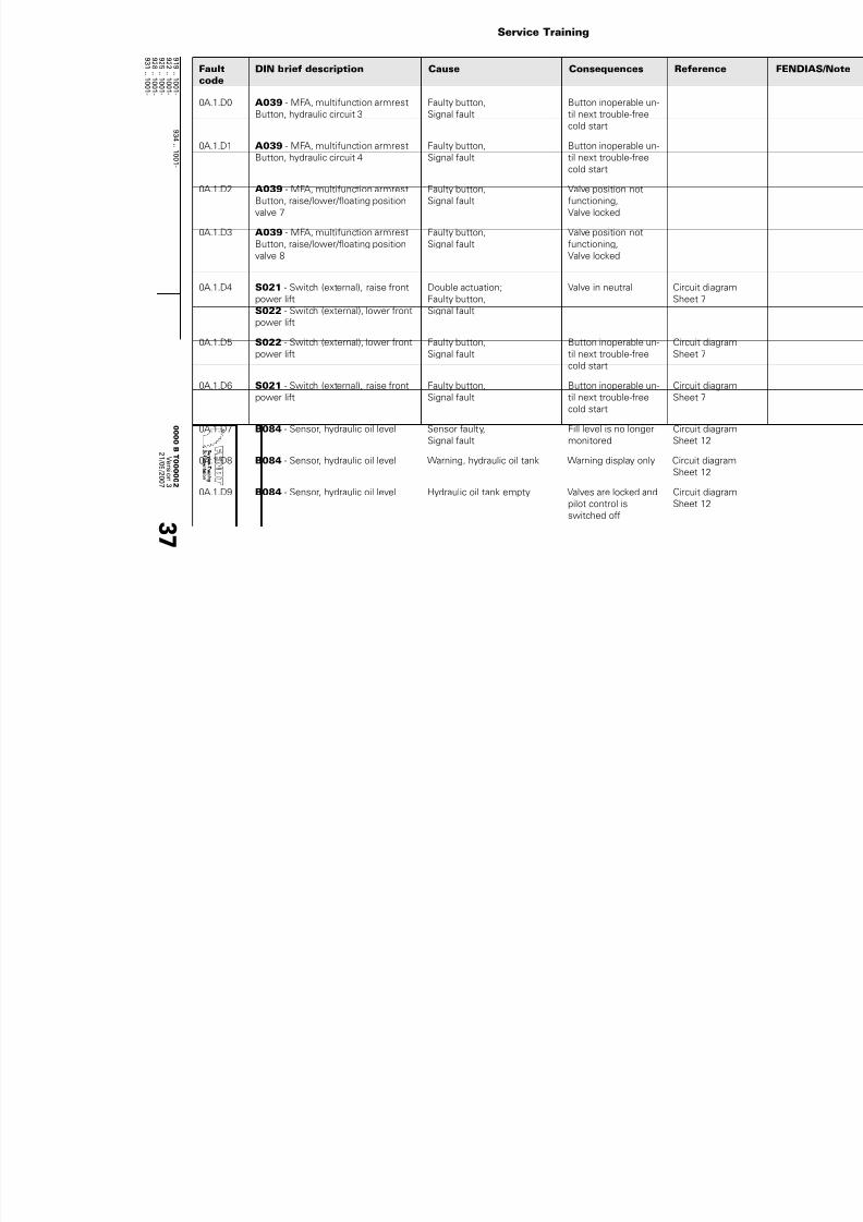
7/17/2019 Failure codes fendt 900 Vario 09 2007
http://slidepdf.com/reader/full/failure-codes-fendt-900-vario-09-2007 175/201
Service Training
9 1
9 ..1
0 0 1 -
9 3 4 ..1 0
0 1 -
9 2 2 ..1
0 0 1 -
9 2
5 ..1
0 0 1 -
9 2
8 ..1
0 0 1 -
9 3 1
1 0 0 1 -
0 0 0 0 BT 0 0 0 0 0 2
V er s i on
3
2 1 / 0 9 / 2 0 0 7
3 7
0A.1.D0 A039 - MFA, multifunction armrest
Button, hydraulic circuit 3
Faulty button,
Signal fault
Button inoperable un-
til next trouble-free
cold start
0A.1.D1 A039 - MFA, multifunction armrest
Button, hydraulic circuit 4
Faulty button,
Signal fault
Button inoperable un-
til next trouble-free
cold start
0A.1.D2 A039 - MFA, multifunction armrest
Button, raise/lower/floating position
valve 7
Faulty button,
Signal fault
Valve position not
functioning,
Valve locked
0A.1.D3 A039 - MFA, multifunction armrest
Button, raise/lower/floating position
valve 8
Faulty button,
Signal fault
Valve position not
functioning,
Valve locked
0A.1.D4 S021 - Switch (external), raise front
power liftS022 - Switch (external), lower front
power lift
Double actuation;
Faulty button,Signal fault
Valve in neutral Circuit diagram
Sheet 7
0A.1.D5 S022 - Switch (external), lower front
power lift
Faulty button,
Signal fault
Button inoperable un-
til next trouble-free
cold start
Circuit diagram
Sheet 7
0A.1.D6 S021 - Switch (external), raise front
power lift
Faulty button,
Signal fault
Button inoperable un-
til next trouble-free
cold start
Circuit diagram
Sheet 7
0A.1.D7 B084 - Sensor, hydraulic oil level Sensor faulty,
Signal fault
Fill level is no longer
monitored
Circuit diagram
Sheet 12
0A.1.D8 B084 - Sensor, hydraulic oil level Warning, hydraulic oil tank Warning display only Circuit diagram
Sheet 12
0A.1.D9 B084 - Sensor, hydraulic oil level Hydraulic oil tank empty Valves are locked and
pilot control is
switched off
Circuit diagram
Sheet 12
Faultcode
DIN brief description Cause Consequences Reference

7/17/2019 Failure codes fendt 900 Vario 09 2007
http://slidepdf.com/reader/full/failure-codes-fendt-900-vario-09-2007 176/201
9 1
9 ..1
0 0 1 -
9 3 4 ..1 0
0 1 -
9 2 2 ..1
0 0 1 -
9 2
5 ..1
0 0 1 -
9 2
8 ..1
0 0 1 -
9 3 1
1 0 0 1 -
0 0 0 0 BT 0 0 0 0 0 2
V er s i on
3
2 1 / 0 9 / 2 0 0 7
3 8
0A.1.DA B013 - Sensor, hydraulic oil tempera-
ture
Warning, hydraulic tempera-
ture sensor too high
Warning display only Circuit diagram
Sheet 12
0A.1.DB B013 - Sensor, hydraulic oil tempera-
ture
Hydraulic temperature sensor
too high
Circuit diagram
Sheet 12
0A.1.DC B013 - Sensor, hydraulic oil tempera-
ture
Warning, hydraulic tempera-
ture sensor not plausible
Warning display only Circuit diagram
Sheet 12
0A.1.DD B063 - Pressure switch, filter con-
tamination (hydraulic circuit)
Filter clogged Warning display only Circuit diagram
Sheet 7
0A.1.DE B063 - Pressure switch, filter con-
tamination (hydraulic circuit)
Faulty button, signal fault Warning display only Circuit diagram
Sheet 7
0A.1.DF Auxiliary control units Prio volume greater than
pump volume
0A.1.EC Trailer brake valve ABV: bypass output 2 high
fault
0A.1.ED Trailer brake valve ABV: bypass output 2 low fault
0A.1.EE Trailer brake valve ABV: bypass output 4 high
fault
0A.1.EF Trailer brake valve ABV: bypass output 4 low fault
0A.1.F0 Y032 - Control pressure solenoid
valve
Short circuit Ub + No valve actuation
possible
Circuit diagram
Sheet 7
0A.1.F2 Y032 - Control pressure solenoid
valve
Current too high, faulty valve
(short circuit to earth)
No valve actuation
possible
Circuit diagram
Sheet 7
0A.1.F3 Y032 - Control pressure solenoid
valve
Break in wiring No valve actuation
possible
Circuit diagram
Sheet 7
0A.1.F4 Y021 - Raise solenoid valve, (front
power lift),
Short circuit to earth, short cir-
cuit to UB or brake in wiring
No raising possible Circuit diagram
Sheet 7
0A.1.F5 Y022 - Lower solenoid valve, (front
power lift),
Short circuit to earth, short cir-
cuit to UB or brake in wiring
No lowering possible Circuit diagram
Sheet 7
Faultcode
DIN brief description Cause Consequences Reference

7/17/2019 Failure codes fendt 900 Vario 09 2007
http://slidepdf.com/reader/full/failure-codes-fendt-900-vario-09-2007 177/201
Service Training
9 1
9 ..1
0 0 1 -
9 3 4 ..1 0
0 1 -
9 2 2 ..1
0 0 1 -
9 2
5 ..1
0 0 1 -
9 2
8 ..1
0 0 1 -
9 3 1
1 0 0 1 -
0 0 0 0 BT 0 0 0 0 0 2
V er s i on
3
2 1 / 0 9 / 2 0 0 7
3 9
0A.1.F6 Y060 - Hydraulic oil pre-heater sole-
noid valve (rear)
Actuation fault No further valve heat-
ing possible
Circuit diagram
Sheet 7
0A.1.F7 Y061 - Hydraulic oil pre-heater sole-
noid valve (front)
Actuation fault No further valve heat-
ing possible
Circuit diagram
Sheet 7
0A.1.F8 Y084 - Control pressure increase so-
lenoid valve in Power Beyond mode
Actuation fault No control pressure
increase possible
Circuit diagram
Sheet 7
0A.1.FA S067 - Switch (external), valve actua-
tion, raise
Faulty button, signal fault Button inoperable un-
til next trouble-free
cold start
Circuit diagram
Sheet 7
0A.1.FB S068 - Switch (external), valve actua-
tion, lower
Faulty button, signal fault Button inoperable un-
til next trouble-free
cold start
Circuit diagram
Sheet 7
0A.1.FC S067 - Switch (external), valve actua-
tion, raise
S068 - Switch (external), valve actua-
tion, lower
Double actuation, faulty but-
ton, signal fault
Circuit diagram
Sheet 7
0A.1.FD Y082 - Lower link stabiliser I sole-
noid valve
Fault with locking No locking possible Circuit diagram
Sheet 9
0A.1.FE Y083 - Lower link stabiliser II sole-
noid valve
Fault with opening No opening possible Circuit diagram
Sheet 9
X stands for the valve number, e.g. 0A.1.10 = position 1 valve does not report to CAN or 0A.1.37 = posit
position 3 valve
0A.1.X0 Y071 - Control valve
Y072 - Control valve
Y074 - Control valveY075 - Control valve
Y076 - Control valve
Y078 - Control valve
Y079 - Control valve
Y080 - Control valve
Valve does not report to CAN
bus (X= valve number)
Valve moves to neu-
tral and locks
Circuit diagram
Sheet 8
Faultcode
DIN brief description Cause Consequences Reference

7/17/2019 Failure codes fendt 900 Vario 09 2007
http://slidepdf.com/reader/full/failure-codes-fendt-900-vario-09-2007 178/201
9 1
9 ..1
0 0 1 -
9 3 4 ..1 0
0 1 -
9 2 2 ..1
0 0 1 -
9 2
5 ..1
0 0 1 -
9 2
8 ..1
0 0 1 -
9 3 1
1 0 0 1 -
0 0 0 0 BT 0 0 0 0 0 2
V er s i on
3
2 1 / 0 9 / 2 0 0 7
4 0
0A.1.X1 Y071 - Control valve
Y072 - Control valve
Y074 - Control valve
Y075 - Control valve
Y076 - Control valveY078 - Control valve
Y079 - Control valve
Y080 - Control valve
EEPROM inconsistent Valve moves to neu-
tral and locks
Circuit diagram
Sheet 8
0A.1.X2 Y071 - Control valve
Y072 - Control valve
Y074 - Control valve
Y075 - Control valve
Y076 - Control valve
Y078 - Control valve
Y079 - Control valve
Y080 - Control valve
Undervoltage (where U < 8V) Valve moves to neu-
tral and locks
Circuit diagram
Sheet 8
0A.1.X3 Y071 - Control valve
Y072 - Control valve
Y074 - Control valve
Y075 - Control valve
Y076 - Control valve
Y078 - Control valve
Y079 - Control valve
Y080 - Control valve
Overvoltage, safe (where U >
18 V)
Valve moves to neu-
tral and locks
Circuit diagram
Sheet 8
0A.1.X4 Y071 - Control valve
Y072 - Control valve
Y074 - Control valve
Y075 - Control valve
Y076 - Control valveY078 - Control valve
Y079 - Control valve
Y080 - Control valve
Valve actuator falls short (fre-
quent cause: brief control
pressure dips or oil too vis-
cous at very low tempera-
tures)
Valve moves to neu-
tral and locks
Circuit diagram
Sheet 8
Faultcode
DIN brief description Cause Consequences Reference

7/17/2019 Failure codes fendt 900 Vario 09 2007
http://slidepdf.com/reader/full/failure-codes-fendt-900-vario-09-2007 179/201
Service Training
9 1
9 ..1
0 0 1 -
9 3 4 ..1 0
0 1 -
9 2 2 ..1
0 0 1 -
9 2
5 ..1
0 0 1 -
9 2
8 ..1
0 0 1 -
9 3 1
1 0 0 1 -
0 0 0 0 BT 0 0 0 0 0 2
V er s i on
3
2 1 / 0 9 / 2 0 0 7
4 1
0A.1.X5 Y071 - Control valve
Y072 - Control valve
Y074 - Control valve
Y075 - Control valve
Y076 - Control valveY078 - Control valve
Y079 - Control valve
Y080 - Control valve
High overvoltage (> 45V) Valve moves to neu-
tral and locks
Circuit diagram
Sheet 8
0A.1.X6 Y071 - Control valve
Y072 - Control valve
Y074 - Control valve
Y075 - Control valve
Y076 - Control valve
Y078 - Control valve
Y079 - Control valve
Y080 - Control valve
Final stage error (pilot control
solenoid valve)
Valve moves to neu-
tral and locks
Circuit diagram
Sheet 8
0A.1.X7 Y071 - Control valve
Y072 - Control valve
Y074 - Control valve
Y075 - Control valve
Y076 - Control valve
Y078 - Control valve
Y079 - Control valve
Y080 - Control valve
Position pickup sensor error Valve moves to neu-
tral and locks
Circuit diagram
Sheet 8
0A.1.X8 Y071 - Control valve
Y072 - Control valve
Y074 - Control valve
Y075 - Control valve
Y076 - Control valveY078 - Control valve
Y079 - Control valve
Y080 - Control valve
Valve actuator does not return
to neutral position (frequent
cause: valve actuator mechan-
ically jams (pilot control or
main actuator) caused by con-tamination in hydraulics area)
Valve remains deflect-
ed when engine is on;
valve locks,
Pilot pressure OFF
Circuit diagram
Sheet 8
Faultcode
DIN brief description Cause Consequences Reference

7/17/2019 Failure codes fendt 900 Vario 09 2007
http://slidepdf.com/reader/full/failure-codes-fendt-900-vario-09-2007 180/201
9 1
9 ..1
0 0 1 -
9 3 4 ..1 0
0 1 -
9 2 2 ..1
0 0 1 -
9 2
5 ..1
0 0 1 -
9 2
8 ..1
0 0 1 -
9 3 1
1 0 0 1 -
0 0 0 0 BT 0 0 0 0 0 2
V er s i on
3
2 1 / 0 9 / 2 0 0 7
4 2
0A.1.X9 Y071 - Control valve
Y072 - Control valve
Y074 - Control valve
Y075 - Control valve
Y076 - Control valveY078 - Control valve
Y079 - Control valve
Y080 - Control valve
Valve actuator not in neutral
position when switched on
(frequent cause: valve actua-
tor mechanically jams (pilot
control or main actuator)caused by contamination in
hydraulics area)
Valve remains deflect-
ed when engine is on;
valve locks,
Pilot pressure OFF
Circuit diagram
Sheet 8
0A.1.XA Y071 - Control valve
Y072 - Control valve
Y074 - Control valve
Y075 - Control valve
Y076 - Control valve
Y078 - Control valve
Y079 - Control valve
Y080 - Control valve
Valve actuator deflected too
far
Valve moves to neu-
tral and locks
Circuit diagram
Sheet 8
0A.1.XB Y071 - Control valve
Y072 - Control valve
Y074 - Control valve
Y075 - Control valve
Y076 - Control valve
Y078 - Control valve
Y079 - Control valve
Y080 - Control valve
Floating position is not
reached (dto. A.1.X4)
Valve moves to neu-
tral and locks
Circuit diagram
Sheet 8
0A.1.XC Y071 - Control valve
Y072 - Control valve
Y074 - Control valve
Y075 - Control valve
Y076 - Control valveY078 - Control valve
Y079 - Control valve
Y080 - Control valve
Manual actuation (occurs
when a valve is deflected
from its neutral position)
All valve positions, no
function;
Valve locked,
Pilot pressure OFF
Circuit diagram
Sheet 8
Faultcode
DIN brief description Cause Consequences Reference

7/17/2019 Failure codes fendt 900 Vario 09 2007
http://slidepdf.com/reader/full/failure-codes-fendt-900-vario-09-2007 181/201
Service Training
9 1
9 ..1
0 0 1 -
9 3 4 ..1 0
0 1 -
9 2 2 ..1
0 0 1 -
9 2
5 ..1
0 0 1 -
9 2
8 ..1
0 0 1 -
9 3 1
1 0 0 1 -
0 0 0 0 BT 0 0 0 0 0 2
V er s i on
3
2 1 / 0 9 / 2 0 0 7
4 3
0A.1.XD Y071 - Control valve
Y072 - Control valve
Y074 - Control valve
Y075 - Control valve
Y076 - Control valveY078 - Control valve
Y079 - Control valve
Y080 - Control valve
Pilot control actuator jams Valve locked,
Pilot pressure OFF
Circuit diagram
Sheet 8
0A.1.XE Y071 - Control valve
Y072 - Control valve
Y074 - Control valve
Y075 - Control valve
Y076 - Control valve
Y078 - Control valve
Y079 - Control valve
Y080 - Control valve
RAM or FLASH test fault Valve moves to neu-
tral and locks, pilot
pressure OFF
Circuit diagram
Sheet 8
0A.1.XF Y071 - Control valve
Y072 - Control valve
Y074 - Control valve
Y075 - Control valve
Y076 - Control valve
Y078 - Control valve
Y079 - Control valve
Y080 - Control valve
No setpoint message Valve moves to neu-
tral and locks
Pilot pressure OFF
Circuit diagram
Sheet 8
0A.1.XF Y071 - Control valve
Y072 - Control valve
Y074 - Control valve
Y075 - Control valve
Y076 - Control valveY078 - Control valve
Y079 - Control valve
Y080 - Control valve
No configuration message. Valve moves to neu-
tral and locks
Pilot pressure OFF
Circuit diagram
Sheet 8
Faultcode
DIN brief description Cause Consequences Reference

7/17/2019 Failure codes fendt 900 Vario 09 2007
http://slidepdf.com/reader/full/failure-codes-fendt-900-vario-09-2007 182/201
9 1
9 ..1
0 0 1 -
9 3 4 ..1 0
0 1 -
9 2 2 ..1
0 0 1 -
9 2
5 ..1
0 0 1 -
9 2
8 ..1
0 0 1 -
9 3 1
1 0 0 1 -
0 0 0 0 BT 0 0 0 0 0 2
V er s i on
3
2 1 / 0 9 / 2 0 0 7
4 4
0A.1.XF Y071 - Control valve
Y072 - Control valve
Y074 - Control valve
Y075 - Control valve
Y076 - Control valveY078 - Control valve
Y079 - Control valve
Y080 - Control valve
Setpoint message not plausi-
ble
Valve moves to neu-
tral and locks
Pilot pressure OFF
Circuit diagram
Sheet 8
0A.1.XF Y071 - Control valve
Y072 - Control valve
Y074 - Control valve
Y075 - Control valve
Y076 - Control valve
Y078 - Control valve
Y079 - Control valve
Y080 - Control valve
Implausible config. message Valve moves to neu-
tral and locks
Pilot pressure OFF
Circuit diagram
Sheet 8
0A.1.XF Y071 - Control valve
Y072 - Control valve
Y074 - Control valve
Y075 - Control valve
Y076 - Control valve
Y078 - Control valve
Y079 - Control valve
Y080 - Control valve
Potentiometer/PW error Valve moves to neu-
tral and locks
Pilot pressure OFF
Circuit diagram
Sheet 8
0B.2.00 A050 - ECU, basic control unit
TEACH-IN
Warning message when en-
gine speed < 400 for se-
quence start at TEACH-IN
0B.2.01 A050 - ECU, basic control unitTEACH-IN
Warning message on canceldue to seat switch no longer
being pressed
0B.2.02 A050 - ECU, basic control unit
TEACH-IN
Warning message if speed is
too high at the start of a se-
quence
Faultcode
DIN brief description Cause Consequences Reference
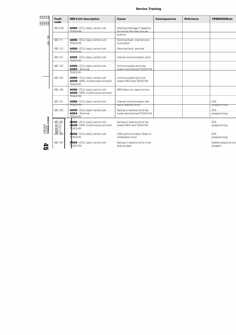
7/17/2019 Failure codes fendt 900 Vario 09 2007
http://slidepdf.com/reader/full/failure-codes-fendt-900-vario-09-2007 183/201
Service Training
9 1
9 ..1
0 0 1 -
9 3 4 ..1 0
0 1 -
9 2 2 ..1
0 0 1 -
9 2
5 ..1
0 0 1 -
9 2
8 ..1
0 0 1 -
9 3 1
1 0 0 1 -
0 0 0 0 BT 0 0 0 0 0 2
V er s i on
3
2 1 / 0 9 / 2 0 0 7
4 5
0B.2.03 A050 - ECU, basic control unit
TEACH-IN
Warning message if speed is
too low at the start of a se-
quence
0B.1.11 A050 - ECU, basic control unit
TEACH-IN
Electrical fault, internal com-
munication
0B.1.12 A050 - ECU, basic control unit
TEACH-IN
Electrical fault, terminal
0B.1.21 A050 - ECU, basic control unit
TEACH-IN
Internal communication error
0B.1.22 A050 - ECU, basic control unit
A054 - Terminal
TEACH-IN
Communication error be-
tween terminal and TEACH-IN
0B.1.23 A050 - ECU, basic control unit
A039 - MFA, multifunction armrest
TEACH-IN
Communication error be-
tween MFA and TEACH-IN
0B.1.25 A050 - ECU, basic control unit
A039 - MFA, multifunction armrest
TEACH-IN
MFA does not report to bus
0B.1.41 A050 - ECU, basic control unit
TEACH-IN
Internal communication sav-
ing or read-out error
0B.1.42 A050 - ECU, basic control unit
A054 - Terminal
TEACH-IN
Saving or read-out error be-
tween terminal and TEACH-IN
0B.1.43 A050 - ECU, basic control unit
A039 - MFA, multifunction armrestTEACH-IN
Saving or read-out error be-
tween MFA and TEACH-IN
0B.1.B0 A050 - ECU, basic control unit
TEACH-IN
CAN communication Teach-In
initialisation error
0B.1.B1 A050 - ECU, basic control unit
TEACH-IN
Saving or read-out error in se-
quence data
Faultcode
DIN brief description Cause Consequences Reference

7/17/2019 Failure codes fendt 900 Vario 09 2007
http://slidepdf.com/reader/full/failure-codes-fendt-900-vario-09-2007 184/201
9 1
9 ..1
0 0 1 -
9 3 4 ..1 0
0 1 -
9 2 2 ..1
0 0 1 -
9 2
5 ..1
0 0 1 -
9 2
8 ..1
0 0 1 -
9 3 1
1 0 0 1 -
0 0 0 0 BT 0 0 0 0 0 2
V er s i on
3
2 1 / 0 9 / 2 0 0 7
4 6
0B.1.B2 A050 - ECU, basic control unit
TEACH-IN
EEPROM checksum error, ini-
tialising sequence data stor-
age
0B.1.B3 A050 - ECU, basic control unit "No memory available for se-
quence data or configuration/
sequence data do not match"
0B.1.B4 A050 - ECU, basic control unit
TEACH-IN
Configuration wizard: error
with writing or reading set-
tings and parameters on trac-
tor start-up/end or formula
management
0F.1.01 E066 - Brake and tail light left Function non-operable Brake light, left
dipped for night driv-
ing
Circuit diagram
Sheet 13/14
0F.1.02 E067 - Brake and tail light right Function non-operable Brake light, rightdipped for night driv-
ing
Circuit diagramSheet 13/14
0F.1.03 E055 - Wide vehicle marker lights,
left
Function non-operable Circuit diagram
Sheet 14
0F.1.04 E054 - Wide vehicle marker lights,
right
Function non-operable Circuit diagram
Sheet 14
0F.1.05 E098 - Drive headlight (main beam),
right
E100 - Drive headlight (main beam),
left
Function non-operable Auto switchover to
additional headlight
Circuit diagram
Sheet 13
0F.1.06 E099 - Drive headlight (dipped
beam), right
E101 - Drive headlight (dipped
beam), left
Function non-operable Auto switchover to
additional headlight
Circuit diagram
Sheet 13
0F.1.07 E003 - H4 additional headlight, right
E004 - H4 additional headlight, left
Function non-operable Auto switchover to
front headlight
Circuit diagram
Sheet 13
Faultcode
DIN brief description Cause Consequences Reference

7/17/2019 Failure codes fendt 900 Vario 09 2007
http://slidepdf.com/reader/full/failure-codes-fendt-900-vario-09-2007 185/201
Service Training
9 1
9 ..1
0 0 1 -
9 3 4 ..1 0
0 1 -
9 2 2 ..1
0 0 1 -
9 2
5 ..1
0 0 1 -
9 2
8 ..1
0 0 1 -
9 3 1
1 0 0 1 -
0 0 0 0 BT 0 0 0 0 0 2
V er s i on
3
2 1 / 0 9 / 2 0 0 7
4 7
0F.1.08 E003 - H4 additional headlight, right
E004 - H4 additional headlight, left
Function non-operable Auto switchover to
front headlight
Circuit diagram
Sheet 13
0F.1.09 E089 - Direction direction indicator,
front left
Function non-operable Circuit diagram
Sheet 15
0F.1.0A E088 - Direction direction indicator,
front right
Function non-operable Circuit diagram
Sheet 15
0F.1.0B E064 - Rear direction indicator, left Function non-operable Circuit diagram
Sheet 16
0F.1.0C E065 - Rear direction indicator, right Function non-operable Circuit diagram
Sheet 16
0F.1.10 M003 - Wiper pump, front Function non-operable Circuit diagram
Sheet 17
0F.1.11 M005 - Wiper pump, rear Function non-operable Circuit diagram
Sheet 17
0F.1.12 A038 - ECU, central electrical sys-
tem
Faulty nozzle heater (planned
although not yet fitted in
X900)
0F.1.13 A038 - ECU, central electrical sys-
tem
Position warning light, termi-
nal 58 faulty
0F.1.15 A036 - Control panel, dashboard
right
Function non-operable
0F.1.16 A037 - Control panel, dashboard left Function non-operable
0F.1.17 E066 - Brake and tail light left Function non-operable Tail lamp, leftswitched for day driv-
ing
Circuit diagramSheet 13/14
0F.1.18 E067 - Brake and tail light right Function non-operable Tail lamp, right
switched for day driv-
ing
Circuit diagram
Sheet 13/14
Faultcode
DIN brief description Cause Consequences Reference

7/17/2019 Failure codes fendt 900 Vario 09 2007
http://slidepdf.com/reader/full/failure-codes-fendt-900-vario-09-2007 186/201
9 1
9 ..1
0 0 1 -
9 3 4 ..1 0
0 1 -
9 2 2 ..1
0 0 1 -
9 2
5 ..1
0 0 1 -
9 2
8 ..1
0 0 1 -
9 3 1
1 0 0 1 -
0 0 0 0 BT 0 0 0 0 0 2
V er s i on
3
2 1 / 0 9 / 2 0 0 7
4 8
0F.1.19 A038 - ECU, central electrical sys-
tem
Sensor supply voltage too
high or too low
0F.1.1A A038 - ECU, central electrical sys-
tem
Main supply voltage too high
or too low
0F.1.1B A038 - ECU, central electrical sys-
tem
Processor supply voltage too
high or too low
0F.1.1D M002 - Front wiper motor Function non-operable Circuit diagram
Sheet 16
0F.1.1E M004 - Rear wiper motor Function non-operable Circuit diagram
Sheet 16
0F.1.1F M010 - Fuel pump Function non-operable Circuit diagram
Sheet 17
0F.1.20 A050 - ECU, basic control unit
A007 - Instrument panel
Communication problem: no
information from instrumentpanel
0F.1.21 A050 - ECU, basic control unit Checksum error over address
range: 0-128d
0F.1.22 A050 - ECU, basic control unit Checksum error over address
range for diagnostic parame-
ters
0F.1.23 A050 - ECU, basic control unit Communication problem: no
information from transmission
(engine speed, theo. speed,
reverse operation)
0F.1.24 A050 - ECU, basic control unit Communication problem: no
information from enhanced
controls (brake)
0F.1.25 A050 - ECU, basic control unit
A039 - MFA, multifunction armrest
Communication problem: no
information from MFA (Hydr3
button, Hydr4 button)
Faultcode
DIN brief description Cause Consequences Reference

7/17/2019 Failure codes fendt 900 Vario 09 2007
http://slidepdf.com/reader/full/failure-codes-fendt-900-vario-09-2007 187/201
Service Training
9 1
9 ..1
0 0 1 -
9 3 4 ..1 0
0 1 -
9 2 2 ..1
0 0 1 -
9 2
5 ..1
0 0 1 -
9 2
8 ..1
0 0 1 -
9 3 1
1 0 0 1 -
0 0 0 0 BT 0 0 0 0 0 2
V er s i on
3
2 1 / 0 9 / 2 0 0 7
4 9
0F.1.26 A050 - ECU, basic control unit Communication problem: no
information from EHL task
(steering angle)
0F.1.27 A038 - ECU, central electrical sys-
tem
Checksum error over address
range for central electrical sys-
tem parameters
0F.1.28 A038 - ECU, central electrical sys-
tem
Error on reading from EEP-
ROM during initialisation
0F.1.29 A039 - MFA, multifunction armrest
Button, hydraulic circuit 3
Faulty button, signal line fault
0F.1.2A A039 - MFA, multifunction armrest
Button, hydraulic circuit 4
Faulty button, signal line fault
0F.1.2B A038 - ECU, central electrical sys-
tem
Function non-operable
0F.1.2C A038 - ECU, central electrical sys-
tem
Valve for left reverse operation
support inoperable
0F.1.2D A038 - ECU, central electrical sys-
tem
Valve for right reverse opera-
tion support inoperable
0F.1.2E M002 - Front wiper motor Warning (end position timed
out)
Wiper tries to restart
0F.1.2F A038 - ECU, central electrical sys-
tem
Initialisation error
0F.1.30 M004 - Rear wiper motor Warning (end position timed
out)
Wiper tries to restart
0F.2.0D A038 - ECU, central electrical sys-
tem
Direction indicator, left trailer
socket faulty
0F.2.0E A038 - ECU, central electrical sys-
tem
Direction indicator, right trailer
socket faulty
Faultcode
DIN brief description Cause Consequences Reference
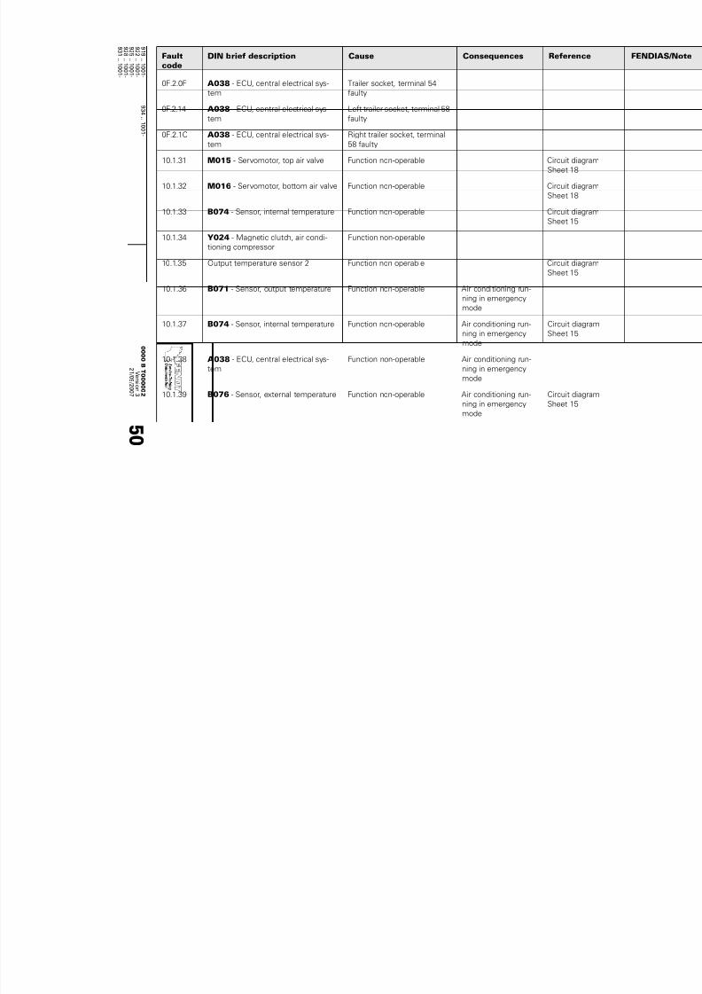
7/17/2019 Failure codes fendt 900 Vario 09 2007
http://slidepdf.com/reader/full/failure-codes-fendt-900-vario-09-2007 188/201
9 1
9 ..1
0 0 1 -
9 3 4 ..1 0
0 1 -
9 2 2 ..1
0 0 1 -
9 2
5 ..1
0 0 1 -
9 2
8 ..1
0 0 1 -
9 3 1
1 0 0 1 -
0 0 0 0 BT 0 0 0 0 0 2
V er s i on
3
2 1 / 0 9 / 2 0 0 7
5 0
0F.2.0F A038 - ECU, central electrical sys-
tem
Trailer socket, terminal 54
faulty
0F.2.14 A038 - ECU, central electrical sys-
tem
Left trailer socket, terminal 58
faulty
0F.2.1C A038 - ECU, central electrical sys-
tem
Right trailer socket, terminal
58 faulty
10.1.31 M015 - Servomotor, top air valve Function non-operable Circuit diagram
Sheet 18
10.1.32 M016 - Servomotor, bottom air valve Function non-operable Circuit diagram
Sheet 18
10.1.33 B074 - Sensor, internal temperature Function non-operable Circuit diagram
Sheet 15
10.1.34 Y024 - Magnetic clutch, air condi-
tioning compressor
Function non-operable
10.1.35 Output temperature sensor 2 Function non-operable Circuit diagram
Sheet 15
10.1.36 B071 - Sensor, output temperature Function non-operable Air conditioning run-
ning in emergency
mode
10.1.37 B074 - Sensor, internal temperature Function non-operable Air conditioning run-
ning in emergency
mode
Circuit diagram
Sheet 15
10.1.38 A038 - ECU, central electrical sys-
tem
Function non-operable Air conditioning run-
ning in emergencymode
10.1.39 B076 - Sensor, external temperature Function non-operable Air conditioning run-
ning in emergency
mode
Circuit diagram
Sheet 15
Faultcode
DIN brief description Cause Consequences Reference

7/17/2019 Failure codes fendt 900 Vario 09 2007
http://slidepdf.com/reader/full/failure-codes-fendt-900-vario-09-2007 189/201
Service Training
9 1
9 ..1
0 0 1 -
9 3 4 ..1 0
0 1 -
9 2 2 ..1
0 0 1 -
9 2
5 ..1
0 0 1 -
9 2
8 ..1
0 0 1 -
9 3 1
1 0 0 1 -
0 0 0 0 BT 0 0 0 0 0 2
V er s i on
3
2 1 / 0 9 / 2 0 0 7
5 1
10.1.3A A053 - ECU, air conditioning control Checksum error, air condition-
ing (Adr 1000d- 1125)
Default parameters
are read from flash
10.1.3B A053 - ECU, air conditioning control Overheating protection or
anti-blocking mechanism
faulty
10.1.3C B073 - Sensor, solar (irradiation) Function non-operable Default parameters
are used
Circuit diagram
Sheet 15
10.1.3D A053 - ECU, air conditioning control Function non-operable
10.1.3E A053 - ECU, air conditioning control
S035 - Switch, high-pressure/low-
pressure (air conditioning system)
Malfunction
15.1.62 Y065 - Raise suspension solenoid
valve
Function non-operable Circuit diagram
Sheet 9
15.1.63 Y064 - Suspension load pressure so-lenoid valve
Inoperable (in X900, this is aproportional valve with PWM
actuation)
Circuit diagramSheet 9
15.1.64 A039 - MFA, multifunction armrest
Button, raise suspension (VA suspen-
sion)
Faulty button, signal fault
15.1.65 A039 - MFA, multifunction armrest
Lock suspension button, FA suspen-
sion
Faulty button, signal fault
15.1.66 Y012 - Solenoid valve, load suspen-
sion
Function non-operable Circuit diagram
Sheet 7
15.1.67 B066 - Sensor, wheel position (left) Sensor faulty,
Signal fault
Circuit diagram
Sheet 9
15.1.68 B068 - Sensor, wheel position (right) Sensor faulty,
Signal fault
Circuit diagram
Sheet 9
Faultcode
DIN brief description Cause Consequences Reference

7/17/2019 Failure codes fendt 900 Vario 09 2007
http://slidepdf.com/reader/full/failure-codes-fendt-900-vario-09-2007 190/201
9 1
9 ..1
0 0 1 -
9 3 4 ..1 0
0 1 -
9 2 2 ..1
0 0 1 -
9 2
5 ..1
0 0 1 -
9 2
8 ..1
0 0 1 -
9 3 1
1 0 0 1 -
0 0 0 0 BT 0 0 0 0 0 2
V er s i on
3
2 1 / 0 9 / 2 0 0 7
5 2
15.1.69 Y063 - Wobble stabiliser solenoid
valve
Function non-operable Circuit diagram
Sheet 9
15.1.6A Y067 - Lock suspension solenoid
valve
Solenoid valve faulty, actua-
tion fault
Circuit diagram
Sheet 9
15.1.6B Y067 - Lock suspension solenoid
valve
Solenoid valve faulty,
Actuation fault
Circuit diagram
Sheet 9
15.1.6C B066 - Sensor, wheel position (left)
B068 - Sensor, wheel position (right)
Position sensor not calibrated Circuit diagram
Sheet 9
15.1.6D A050 - ECU, basic control unit Checksum error, suspension
15.1.6E B066 - Sensor, wheel position (left)
B068 - Sensor, wheel position (right)
Plausibility error Circuit diagram
Sheet 9
18.1.01 A039 - MFA, multifunction armrest
Autoguide
Diagnostics button, partial ac-
tivation in MFA
18.1.02 A039 - MFA, multifunction armrest
Autoguide
Diagnostics button, full activa-
tion in MFA
18.1.03 A039 - MFA, multifunction armrest MFA fails to report
18.1.06 S053 - Switch, driver seat Diagnostics, seat switch
18.1.07 Y085 - Steering switch-off (Autogu-
ide) solenoid valve
Diagnostics, steering wheel
shut-off valve
Circuit diagram
Sheet 9
18.1.08 Y086 - Steering switch-off (Autogu-
ide) solenoid valve
Diagnostics, pilot pressure
valve
Circuit diagram
Sheet 9
18.1.1A B067 - Sensor, steering angle Diagnostics, steering angle
sensor
18.1.1C B067 - Sensor, steering angle Invalid calibration values for
steering angle sensor in EEP-
ROM
18.1.2A B081 - Steering wheel sensor (360°) Diagnostics, steering wheel
sensor
Faultcode
DIN brief description Cause Consequences Reference

7/17/2019 Failure codes fendt 900 Vario 09 2007
http://slidepdf.com/reader/full/failure-codes-fendt-900-vario-09-2007 191/201
Service Training
9 1
9 ..1
0 0 1 -
9 3 4 ..1 0
0 1 -
9 2 2 ..1
0 0 1 -
9 2
5 ..1
0 0 1 -
9 2
8 ..1
0 0 1 -
9 3 1
1 0 0 1 -
0 0 0 0 BT 0 0 0 0 0 2
V er s i on
3
2 1 / 0 9 / 2 0 0 7
5 3
18.1.2C B081 - Steering wheel sensor (360°) Invalid calibration values for
steering wheel sensor in EEP-
ROM
18.1.30 Y087 - Steering valve block, Autogu-
ide
Unknown error from steering
valve
18.1.31 Y087 - Steering valve block, Autogu-
ide
Error with supply voltage from
steering valve
18.1.32 Y087 - Steering valve block, Autogu-
ide
Warning for steering valve ac-
tuator position
18.1.33 Y087 - Steering valve block, Autogu-
ide
Error with steering valve actu-
ator position
18.1.34 Y087 - Steering valve block, Autogu-
ide
Error with steering valve actu-
ation
18.1.35 Y087 - Steering valve block, Autogu-ide
Error with steering valve hard-ware
18.1.36 Y087 - Steering valve block, Autogu-
ide
Warning for steering valve
FLASH, E²PROM and soft-
ware
18.1.37 Y087 - Steering valve block, Autogu-
ide
Error with steering valve
FLASH, E²PROM and soft-
ware
18.1.3A Y087 - Steering valve block, Autogu-
ide
No response from valve
18.1.3B Y087 - Steering valve block, Autogu-ide
Steering valve does not returnto neutral on switch-off
18.1.3C Y087 - Steering valve block, Autogu-
ide
Invalid calibration values for
steering valve in EEPROM
18.1.4A A050 - ECU, basic control unit Communication with TopDock
interrupted
Last steering com-
mand is retained
Faultcode
DIN brief description Cause Consequences Reference

7/17/2019 Failure codes fendt 900 Vario 09 2007
http://slidepdf.com/reader/full/failure-codes-fendt-900-vario-09-2007 192/201
9 1
9 ..1
0 0 1 -
9 3 4 ..1 0
0 1 -
9 2 2 ..1
0 0 1 -
9 2
5 ..1
0 0 1 -
9 2
8 ..1
0 0 1 -
9 3 1
1 0 0 1 -
0 0 0 0 BT 0 0 0 0 0 2
V er s i on
3
2 1 / 0 9 / 2 0 0 7
5 4
18.1.4C A050 - ECU, basic control unit Invalid settings (BSAC) for
controller in EEPROM
18.1.5C A050 - ECU, basic control unit Invalid parameters for control-
ler in EEPROM
18.1.66 Y087 - Steering valve block, Autogu-
ide
Wire for flow measurement
broken or short circuited
18.1.69 Y087 - Steering valve block, Autogu-
ide
Supply voltage over 32 V
18.1.6A Y087 - Steering valve block, Autogu-
ide
Supply voltage below 10 V
18.1.6B Y087 - Steering valve block, Autogu-
ide
Actuator cannot reach neutral
18.1.6C Y087 - Steering valve block, Autogu-
ide
Actuator not in neutral during
"RUNUP"
18.1.6D Y087 - Steering valve block, Autogu-
ide
Actuator position greater than
reference position
18.1.7F Y087 - Steering valve block, Autogu-
ide
EHL system error
18.2.05 S053 - Switch, driver seat Seat not "loaded" when steer-
ing is activated
18.2.40 A050 - ECU, basic control unit Warning message when at-
tempting to fully activate —
no BSAC connection
18.2.70 Y087 - Steering valve block, Autogu-
ide
Warning message when ISO
is inactive
If the following errors occur (1E.1…) they must be deleted in the engine control unit following error corre
1E.1.00 A051 - ECU, engine control unit
(EDC 7).
Original error, Deutz
Faultcode
DIN brief description Cause Consequences Reference

7/17/2019 Failure codes fendt 900 Vario 09 2007
http://slidepdf.com/reader/full/failure-codes-fendt-900-vario-09-2007 193/201
Service Training
9 1
9 ..1
0 0 1 -
9 3 4 ..1 0
0 1 -
9 2 2 ..1
0 0 1 -
9 2
5 ..1
0 0 1 -
9 2
8 ..1
0 0 1 -
9 3 1
1 0 0 1 -
0 0 0 0 BT 0 0 0 0 0 2
V er s i on
3
2 1 / 0 9 / 2 0 0 7
5 5
1E.1.01 G001 - Battery 1 (12 VDC) Input, battery,
battery voltage outside
setpoint range
Start not possible
1E.1.02 B092 - Sensor, charge air pressure/
temperature
Sensor, boost pressure,
break in wiring or short circuit.
Charge pressure
outside setpoint range
Reduced power Circuit diagram
Sheet 22
1E.1.03 B092 - Sensor, charge air pressure/
temperature
Sensor
Charge air temperature, break
in wiring or short circuit.
Charge air temperature above
setpoint value
Reduced power Circuit diagram
Sheet 22
1E.1.04 B089 - Temperature sensor, Deutz Sensor, coolant temperature:
break in wiring or short circuit.
Coolant temperature outside
setpoint area
Circuit diagram
Sheet 22
1E.1.06 B085 - Camshaft speed
B088 - Crankshaft speed
Camshaft sensor faulty or no
signal;
Crankshaft sensor faulty or no
signal; camshaft/crankshaft
speed signals out of phase
Starting possible after
prolonged unsuc-
cessful attempt, en-
gine runs "rough"
Circuit diagram
Sheet 22
1E.1.07 B091 - Sensor, water in fuel Fuel filter/water sedimentor
sensor, brake in wiring or
short circuit
Water level above setpoint
range
Drain water from fuel
filter
Circuit diagram
Sheet 22
1E.1.08 B087 - Fuel low pressure Brake in wiring or short circuitFuel low pressure outside set-
point rage
Check fuel system,possibly air in system
or fuel filter clogged
Circuit diagramSheet 22
1E.1.0A A039 - MFA, multifunction armrest
Potentiometer, hand throttle
Brake in wiring or short circuit
Idle sensor signal not plausi-
ble
Faultcode
DIN brief description Cause Consequences Reference

7/17/2019 Failure codes fendt 900 Vario 09 2007
http://slidepdf.com/reader/full/failure-codes-fendt-900-vario-09-2007 194/201
9 1
9 ..1
0 0 1 -
9 3 4 ..1 0
0 1 -
9 2 2 ..1
0 0 1 -
9 2
5 ..1
0 0 1 -
9 2
8 ..1
0 0 1 -
9 3 1
1 0 0 1 -
0 0 0 0 BT 0 0 0 0 0 2
V er s i on
3
2 1 / 0 9 / 2 0 0 7
5 6
1E.1.0E B090 - Sensor, oil pressure Brake in wiring or short circuit.
Oil pressure outside of set-
point range
Circuit diagram
Sheet 22
1E.1.0F B079 - Sensor (combined), engine oil
temperature/engine oil level
Sensor faulty,
Signal fault
Circuit diagram
Sheet 21
1E.1.12 S002 - Switch, ignition Pin 50,
Ignition starter switch sticking
Circuit diagram
Sheet 15
1E.1.13 A051 - ECU, engine control unit
(EDC 7).
Travel speed above setpoint
range, signal fault
1E.1.14 B055 - Sensor, foot throttle Brake in wiring or short circuit
Signal does not match idle
sensor signal
Speed maintained,
can be used by hand
throttle by increasing
speed briefly
Circuit diagram
Sheet 21
1E.1.21 K063 - Heater flange relay Brake in wiring or short circuit Pre-heater inoperable Circuit diagram
Sheet 22
1E.1.22 K063 - Heater flange relay Break in wiring or incorrectly
connected
Pre-heater inoperable Circuit diagram
Sheet 22
1E.1.23 S047 - Switch, engine brake Brake in wiring or short circuit Circuit diagram
Sheet 21
1E.1.24 Y006 - Solenoid valve, engine brake Faulty valve, faulty actuation
1E.1.25 Y006 - Solenoid valve, engine brake Brake in wiring or short circuit
1E.1.26 Y024 - Magnetic clutch, air condi-tioning compressor
Brake in wiring or short circuit
1E.1.27 G001 - Battery 1 (12 VDC) Short circuit to battery or
earth
Start not possible
Faultcode
DIN brief description Cause Consequences Reference

7/17/2019 Failure codes fendt 900 Vario 09 2007
http://slidepdf.com/reader/full/failure-codes-fendt-900-vario-09-2007 195/201
Service Training
9 1
9 ..1
0 0 1 -
9 3 4 ..1 0
0 1 -
9 2 2 ..1
0 0 1 -
9 2
5 ..1
0 0 1 -
9 2
8 ..1
0 0 1 -
9 3 1
1 0 0 1 -
0 0 0 0 BT 0 0 0 0 0 2
V er s i on
3
2 1 / 0 9 / 2 0 0 7
5 7
1E.1.2C K065 - Starter relay Brake in wiring or short circuit Start not possible Circuit diagram
Sheet 21
1E.1.30 B004 - Vacuum switch (air filter) Pressure loss above setpoint
range
Loss of power
Clean/replace air filter
Circuit diagram
Sheet 21
1E.1.34 S034 - Switch, coolant level Coolant outside of setpoint
level
Check coolant level Circuit diagram
Sheet 21
1E.1.37 A051 - ECU, engine control unit
(EDC 7).
Fan speed exceeds target
range
1E.1.3A A051 - ECU, engine control unit
(EDC 7).
Misfiring
1E.1.50 Y091 - Dispensing unit (fuel) Dispensing unit not connect-
ed, short circuit to battery or
earth
Message that the en-
gine stops after ap-
prox. 5 minutes
appears
Circuit diagram
Sheet 22
1E.1.51 B086 - Rail pressure sensor
Pressure-limiting valve, mechanical
rail pressure
Cut-off valve, rail pressure
fails to open
Message that the en-
gine stops after ap-
prox. 5 minutes
appears
1E.1.52 B086 - Rail pressure sensor Brake in wiring or short circuit Message that the en-
gine stops after ap-
prox. 5 minutes
appears
Circuit diagram
Sheet 22
1E.1.53 B086 - Rail pressure sensor Rail pressure outside setpoint
range
Message that the en-
gine stops after ap-
prox. 5 minutes
appears
Circuit diagram
Sheet 22
1E.1.54 B086 - Rail pressure sensor Compression test active Rail pressure moni-
toring deactivated
1E.1.60 A051 - ECU, engine control unit
(EDC 7).
Misfiring on several cylinders
Faultcode
DIN brief description Cause Consequences Reference

7/17/2019 Failure codes fendt 900 Vario 09 2007
http://slidepdf.com/reader/full/failure-codes-fendt-900-vario-09-2007 196/201
9 1
9 ..1
0 0 1 -
9 3 4 ..1 0
0 1 -
9 2 2 ..1
0 0 1 -
9 2
5 ..1
0 0 1 -
9 2
8 ..1
0 0 1 -
9 3 1
1 0 0 1 -
0 0 0 0 BT 0 0 0 0 0 2
V er s i on
3
2 1 / 0 9 / 2 0 0 7
5 8
1E.1.61 A051 - ECU, engine control unit
(EDC 7).
Misfiring on cylinder 1
1E.1.62 A051 - ECU, engine control unit
(EDC 7).
Misfiring on cylinder 2
1E.1.63 A051 - ECU, engine control unit
(EDC 7).
Misfiring on cylinder 3
1E.1.64 A051 - ECU, engine control unit
(EDC 7).
Misfiring on cylinder 4
1E.1.65 A051 - ECU, engine control unit
(EDC 7).
Misfiring on cylinder 5
1E.1.66 A051 - ECU, engine control unit
(EDC 7).
Misfiring on cylinder 6
1E.1.70 A051 - ECU, engine control unit
(EDC 7).
Start of injection period in cyl-
inder 1 outside setpoint rangeor absent.
1E.1.71 A051 - ECU, engine control unit
(EDC 7).
Start of injection period in cyl-
inder 2 outside setpoint range
or absent.
1E.1.72 A051 - ECU, engine control unit
(EDC 7).
Start of injection period in cyl-
inder 3 outside setpoint range
or absent.
1E.1.73 A051 - ECU, engine control unit
(EDC 7).
Start of injection period in cyl-
inder 4 outside setpoint range
or absent.
1E.1.74 A051 - ECU, engine control unit
(EDC 7).
Start of injection period in cyl-
inder 5 outside setpoint range
or absent.
1E.1.75 A051 - ECU, engine control unit
(EDC 7).
Start of injection period in cyl-
inder 6 outside setpoint range
or absent.
Faultcode
DIN brief description Cause Consequences Reference

7/17/2019 Failure codes fendt 900 Vario 09 2007
http://slidepdf.com/reader/full/failure-codes-fendt-900-vario-09-2007 197/201
Service Training
9 1
9 ..1
0 0 1 -
9 3 4 ..1 0
0 1 -
9 2 2 ..1
0 0 1 -
9 2
5 ..1
0 0 1 -
9 2
8 ..1
0 0 1 -
9 3 1
1 0 0 1 -
0 0 0 0 BT 0 0 0 0 0 2
V er s i on
3
2 1 / 0 9 / 2 0 0 7
5 9
1E.1.78 A051 - ECU, engine control unit
(EDC 7).
Short circuit in cylinder bank 1
injector valves
Cylinder switch-off
1E.1.79 A051 - ECU, engine control unit
(EDC 7).
Break in wiring of cylinder
bank 1 injector valves
Cylinder switch-off
1E.1.7A A051 - ECU, engine control unit
(EDC 7).
Short circuit in cylinder bank 2
injector valves
Cylinder switch-off
1E.1.7B A051 - ECU, engine control unit
(EDC 7).
Break in wiring of cylinder
bank 2 injector valves
Cylinder switch-off
1E.1.7C A051 - ECU, engine control unit
(EDC 7).
Short circuit or break in wiring
to injector valve 1
Injection failure
1E.1.7D A051 - ECU, engine control unit
(EDC 7).
Short circuit or break in wiring
to injector valve 2
Injection failure
1E.1.7E A051 - ECU, engine control unit
(EDC 7).
Short circuit or break in wiring
to injector valve 3
Injection failure
1E.1.7F A051 - ECU, engine control unit
(EDC 7).
Short circuit or break in wiring
to injector valve 4
Injection failure
1E.1.80 A051 - ECU, engine control unit
(EDC 7).
Short circuit or break in wiring
to injector valve 5
Injection failure
1E.1.81 A051 - ECU, engine control unit
(EDC 7).
Short circuit or break in wiring
to injector valve 6
1E.1.90 Y094 - Actuator unit, AGR (exhaust
gas recirculation)
Short circuit to battery, earth,
break in wiring or short circuit
Reduction in power
1E.1.B0 A051 - ECU, engine control unit(EDC 7). CAN message, no throttlepedal or outside setpoint
range
Circuit diagramSheet 21
1E.1.B1 A051 - ECU, engine control unit
(EDC 7).
CAN message, no control
function mode
Circuit diagram
Sheet 21
1E.1.B2 A051 - ECU, engine control unit
(EDC 7).
CAN message, no engine pro-
tection mechanism
Circuit diagram
Sheet 21
Faultcode
DIN brief description Cause Consequences Reference

7/17/2019 Failure codes fendt 900 Vario 09 2007
http://slidepdf.com/reader/full/failure-codes-fendt-900-vario-09-2007 198/201
9 1
9 ..1
0 0 1 -
9 3 4 ..1 0
0 1 -
9 2 2 ..1
0 0 1 -
9 2
5 ..1
0 0 1 -
9 2
8 ..1
0 0 1 -
9 3 1
1 0 0 1 -
0 0 0 0 BT 0 0 0 0 0 2
V er s i on
3
2 1 / 0 9 / 2 0 0 7
6 0
1E.1.B3 A051 - ECU, engine control unit
(EDC 7).
CAN message, no pre-heater
or engine command
Circuit diagram
Sheet 21
1E.1.B4 A051 - ECU, engine control unit
(EDC 7).
No Tempomat cruise control
CAN message
Circuit diagram
Sheet 21
1E.1.B5 A051 - ECU, engine control unit
(EDC 7).
No engine temperature CAN
message
Circuit diagram
Sheet 21
1E.1.B6 A051 - ECU, engine control unit
(EDC 7).
No switch outputs CAN mes-
sage
Circuit diagram
Sheet 21
1E.1.B7 A051 - ECU, engine control unit
(EDC 7).
No speedometer signal CAN
message
Circuit diagram
Sheet 21
1E.1.B8 A051 - ECU, engine control unit
(EDC 7).
CAN-message missing Circuit diagram
Sheet 21
1E.1.B9 A051 - ECU, engine control unit
(EDC 7).
CAN-message missing Circuit diagram
Sheet 21
1E.1.BA A051 - ECU, engine control unit
(EDC 7).
CAN-message missing Circuit diagram
Sheet 21
1E.1.BB A051 - ECU, engine control unit
(EDC 7).
CAN-message missing Circuit diagram
Sheet 21
1E.1.BC A051 - ECU, engine control unit
(EDC 7).
CAN-message missing Circuit diagram
Sheet 21
1E.1.BD A051 - ECU, engine control unit
(EDC 7).
CAN-message missing Circuit diagram
Sheet 21
1E.1.BE A051 - ECU, engine control unit(EDC 7). CAN-message missing Circuit diagramSheet 21
1E.1.BF A051 - ECU, engine control unit
(EDC 7).
CAN-message missing Circuit diagram
Sheet 21
1E.1.C0 A051 - ECU, engine control unit
(EDC 7).
CAN-message missing Circuit diagram
Sheet 21
Faultcode
DIN brief description Cause Consequences Reference

7/17/2019 Failure codes fendt 900 Vario 09 2007
http://slidepdf.com/reader/full/failure-codes-fendt-900-vario-09-2007 199/201
Service Training
9 1
9 ..1
0 0 1 -
9 3 4 ..1 0
0 1 -
9 2 2 ..1
0 0 1 -
9 2
5 ..1
0 0 1 -
9 2
8 ..1
0 0 1 -
9 3 1
1 0 0 1 -
0 0 0 0 BT 0 0 0 0 0 2
V er s i on
3
2 1 / 0 9 / 2 0 0 7
6 1
1E.1.C1 A051 - ECU, engine control unit
(EDC 7).
CAN bus times out with at
least one sent message
Circuit diagram
Sheet 21
1E.1.C2 A051 - ECU, engine control unit
(EDC 7).
CAN bus A, break in wiring or
short circuit
Possible to drive with
foot throttle/throttle
pedal
Circuit diagram
Sheet 21
1E.1.C3 A051 - ECU, engine control unit
(EDC 7).
CAN bus B, break in wiring or
short circuit
Possible to drive with
foot throttle/throttle
pedal
Circuit diagram
Sheet 21
1E.1.C4 A051 - ECU, engine control unit
(EDC 7).
CAN bus C, break in wiring or
short circuit
Possible to drive with
foot throttle/throttle
pedal
Circuit diagram
Sheet 21
1E.1.D0 A051 - ECU, engine control unit
(EDC 7).
Faulty external pressure sen-
sor
1E.1.D1 A051 - ECU, engine control unit
(EDC 7).
Faulty engine control unit
1E.1.D2 A051 - ECU, engine control unit
(EDC 7).
EEPROM memory access
1E.1.D3 A051 - ECU, engine control unit
(EDC 7).
Faulty injector valve (chip)
1E.1.D4 A051 - ECU, engine control unit
(EDC 7).
Faulty injector valve (chip)
1E.1.D5 A051 - ECU, engine control unit
(EDC 7).
Faulty engine control
1E.1.D6 A051 - ECU, engine control unit(EDC 7).
Engine monitoring systemoverloaded
1E.1.D7 A051 - ECU, engine control unit
(EDC 7).
Incorrect voltage for internal 5
V reference source 1
1E.1.D8 A051 - ECU, engine control unit
(EDC 7).
Incorrect voltage for internal 5
V reference source 2
Faultcode
DIN brief description Cause Consequences Reference

7/17/2019 Failure codes fendt 900 Vario 09 2007
http://slidepdf.com/reader/full/failure-codes-fendt-900-vario-09-2007 200/201
9 1
9 ..1
0 0 1 -
9 3 4 ..1 0
0 1 -
9 2 2 ..1
0 0 1 -
9 2
5 ..1
0 0 1 -
9 2
8 ..1
0 0 1 -
9 3 1
1 0 0 1 -
0 0 0 0
BT 0 0 0 0 0 2
V er s i on
3
2 1
/ 0 9 / 2 0 0 7
6 2
1E.1.D9 A051 - ECU, engine control unit
(EDC 7).
Incorrect voltage for internal 5
V reference source 3
1E.1.DB A051 - ECU, engine control unit
(EDC 7).
Faulty serial communication
interface1E.1.F0 A051 - ECU, engine control unit
(EDC 7).
Manipulation protection
Torque envelope curve manip-
ulation detected
Reduction in power
Faultcode
DIN brief description Cause Consequences Reference

7/17/2019 Failure codes fendt 900 Vario 09 2007
http://slidepdf.com/reader/full/failure-codes-fendt-900-vario-09-2007 201/201