Failure Analysis & Design of 500 Bedded Ladies Hostel at ... · software package staad pro. ......
7
International Journal of Innovative Research in Engineering & Management (IJIREM) ISSN: 2350-0557, Volume-5, Issue-2, March-2018 Copyright © 2018. Innovative Research Publications. All Rights Reserved 76 Failure Analysis & Design of 500 Bedded Ladies Hostel at Cutm, Bhubaneswar ABSTRACT To analyze and design a Multistoried building by using a software package staad pro. For analyzing a multi storied building one has to consider all the possible loadings and see that the structure is safe against all possible loading conditions. There are several methods for analysis of different frames like kani’s method, cantilever method, portal method, Matrix method. The present project deals with the analysis of a multi storeyed residential building of G+4. We conclude that staad pro is a very powerful tool which can save much time and is very accurate in Designs. STAAD. Pro has a very interactive user interface which allows the users to draw the frame and input the load values and dimensions. Then according to the specified criteria assigned it analyses the structure and designs the members with reinforcement details for RCC frames. We continued with our work with some more multi-storeyed 2-D and 3-D frames under various load combinations. Our final work was the proper analysis and design of a G + 4 3-D RCC frame under various load combinations. Key words: Analysis, Beam, column, Design, Multi- storied 1. INTRODUCTION Reinforced concrete buildings consist of floor slab, beams, columns and walls continuously placed to form rigid monolithic systems. Such a continuous system leads to grater redundancy, reduced moments and distributes the load more evenly .the floor slab resets on a system of interconnected beams. The beams may span between columns, or one side beam and side column, or between cross beams. A building frame is a three-dimensional structure or a space structure. It may be possible to idealize such a structure as a system of interconnected two –dimensional vertical frames may be analyzed independently of each other. In case it is not possible to idealize a building as a series of mutually perpendicular 2D frames, it needs to analyze as a 3D space frame. The first few floors may be used for car parking and the upper floors may be used for residential or office purpose. The ground floor plan may be different than those of the upper floors. The floor plan of first floor to top floor, or one or two floors below may be the same.The top one or few more floors may be different than the middle floors. Before proceeding for the design of a multistoried building, there is a need to very carefully study architectural drawings and geotechnical report of the site.A building frame consists of number of bays and storey. A multi-storey, multi-paneled frame is a complicated statically intermediate structure. A design R.C building of G+4 storey frame work is taken up. The building in plan consists of columns built monolithically forming a network. The size of building is 26910 sqft.The design is made using software on structural analysis design (staad-pro). The building subjected to both the vertical loads as well as horizontal loads. The vertical load consists of dead load of structural components such as beams, columns, slabs etc and live loads. The horizontal load consists of the wind forces thus building is designed for dead load, live load and wind load as per [1]IS 875. The building is designed as two dimensional vertical frame and analyzed for the maximum and minimum bending moments and shear forces by trial and error methods as per [2] IS 456-2000. The help is taken by software available in institute and the computations of loads, moments and shear forces and obtained from this software. [8] Pilli and menon studied the compressive strength characteristics in buildings [9] Jain revised the study of high rise building by laws 2. EXPERIMENATAL DETAILS Analysis and design up to failure condition of beams and column. Generating structural framing plan. Creating model in STAAD PRO. Application of loads on the member. Analysis of the structure. Design the structure (manual design). MIX DESIGN FOR FOUNDATION Mix design is the science of determining the relative proportion of ingredients of concrete to achieve desired properties in the most economical way. The mix design for M25 grade for pile foundations are provided here is for reference purpose only. 2.1 Material Testing Specific gravity of cement= 2.63 Specific gravity of fine aggregate= 2.89 Specific gravity of coarse aggregate= 2.70 Grading of fine aggregate= zone III 2.2 Required Material a) GRADE DESIGNATION=M25 b) TYPE OF CEMENT=RAMCO(PPC) CEMENT c) TARGET STRENGTH=31.6 N/MM2(IS 10262) d) W/C RATIO=0.45(IS 456 Table5) e) WATER CONTENT=197 KG (IS 10262 Table2) f) CEMENT CONTENT= 437.7KG g) VOLUME OF FINE AGGREGATE=0.415 h) VOLUME OF COARSE AGGREGATE=0.585 Dipteemayee Jena Centurion University of Technology & Management, Bhubaneswar India [email protected] Dr. Manoj Kumar Rath, Corresponding Author Centurion University of Technology & Management, Bhubaneswar India [email protected]
Transcript of Failure Analysis & Design of 500 Bedded Ladies Hostel at ... · software package staad pro. ......
International Journal of Innovative Research in Engineering & Management (IJIREM)
ISSN: 2350-0557, Volume-5, Issue-2, March-2018
Copyright © 2018. Innovative Research Publications. All Rights Reserved 76
Failure Analysis & Design of 500 Bedded Ladies Hostel
at Cutm, Bhubaneswar
ABSTRACT To analyze and design a Multistoried building by using a
software package staad pro. For analyzing a multi storied building one has to consider all the possible loadings and see that the structure is safe against all possible loading conditions. There are several methods for analysis of different frames like kani’s method, cantilever method, portal method, Matrix method. The present project deals with the analysis of a multi storeyed residential building of G+4. We conclude that staad pro is a very powerful tool which can save much time
and is very accurate in Designs. STAAD. Pro has a very interactive user interface which allows the users to draw the frame and input the load values and dimensions. Then according to the specified criteria assigned it analyses the structure and designs the members with reinforcement details for RCC frames. We continued with our work with some more multi-storeyed 2-D and 3-D frames under various load combinations. Our final work was the proper analysis and
design of a G + 4 3-D RCC frame under various load combinations.
Key words: Analysis, Beam, column, Design, Multi-
storied
1. INTRODUCTION Reinforced concrete buildings consist of floor slab, beams, columns and walls continuously placed to form rigid monolithic systems. Such a continuous system leads to grater
redundancy, reduced moments and distributes the load more evenly .the floor slab resets on a system of interconnected beams. The beams may span between columns, or one side beam and side column, or between cross beams. A building frame is a three-dimensional structure or a space structure. It may be possible to idealize such a structure as a system of interconnected two –dimensional vertical frames may be analyzed independently of each other. In case it is not possible to idealize a building as a series of mutually perpendicular 2D
frames, it needs to analyze as a 3D space frame. The first few floors may be used for car parking and the upper floors may be used for residential or office purpose. The ground floor plan may be different than those of the upper floors. The floor plan of first floor to top floor, or one or two floors below may be the same.The top one or few more floors may be different than the middle floors. Before proceeding for the design of a multistoried building, there is a need to very carefully study
architectural drawings and geotechnical report of the site.A building frame consists of number of bays and storey. A multi-storey, multi-paneled frame is a complicated statically intermediate structure. A design R.C building of G+4 storey
frame work is taken up. The building in plan consists of columns built monolithically forming a network. The size of building is 26910 sqft.The design is made using software on structural analysis design (staad-pro). The building subjected to both the vertical loads as well as horizontal loads. The
vertical load consists of dead load of structural components such as beams, columns, slabs etc and live loads. The horizontal load consists of the wind forces thus building is designed for dead load, live load and wind load as per [1]IS 875. The building is designed as two dimensional vertical frame and analyzed for the maximum and minimum bending moments and shear forces by trial and error methods as per [2] IS 456-2000. The help is taken by software available in
institute and the computations of loads, moments and shear forces and obtained from this software. [8] Pilli and menon studied the compressive strength characteristics in buildings [9] Jain revised the study of high rise building by laws
2. EXPERIMENATAL DETAILS Analysis and design up to failure condition of beams
and column.
Generating structural framing plan.
Creating model in STAAD PRO.
Application of loads on the member.
Analysis of the structure.
Design the structure (manual design).
MIX DESIGN FOR FOUNDATION Mix design is the science of determining the relative proportion of ingredients of concrete to achieve desired properties in the most economical way. The mix design for M25 grade for pile foundations are provided here is for reference purpose only.
2.1 Material Testing Specific gravity of cement= 2.63
Specific gravity of fine aggregate= 2.89
Specific gravity of coarse aggregate= 2.70
Grading of fine aggregate= zone III
2.2 Required Material a) GRADE DESIGNATION=M25 b) TYPE OF CEMENT=RAMCO(PPC) CEMENT c) TARGET STRENGTH=31.6 N/MM2(IS 10262) d) W/C RATIO=0.45(IS 456 Table5) e) WATER CONTENT=197 KG (IS 10262 Table2) f) CEMENT CONTENT= 437.7KG g) VOLUME OF FINE AGGREGATE=0.415 h) VOLUME OF COARSE AGGREGATE=0.585
Dipteemayee Jena
Centurion University of Technology &
Management, Bhubaneswar India
Dr. Manoj Kumar Rath, Corresponding Author
Centurion University of Technology & Management, Bhubaneswar
India

Failure Analysis & Design of 500 Bedded Ladies Hostel at Cutm, Bhubaneswar
Copyright © 2018. Innovative Research Publications. All Rights Reserved 77
2.3 Mix Design Calculation (a) Volume of concrete=1m3 (b) Volume of cement = Mass of cement /Specific gravity of cement×1/1000 =437.77/2.7 × 1/1000 =0.162m3 (c) Volume of water = Mass of water / specific gravity o water
× 1 /1000=197/1 × 1/1000 =0.197m3 (d) Volume of all aggregate = [a-(b + c )] = [1-(0.162+0.197)] = 0.641m3 (e) Mass of coarse aggregate = d× volume of coarse aggregate × specific gravity of c.a×1000 = 0.641×0.585×2.7×1000 = 1012.45kg (f) Mass of fine aggregate= d× volume of fine aggregate×
specific gravity of fine aggregate
=0.415×0.641×2.89×1000= 768.78kg (g) Cement required=437.77kg (h) Water required=197kg/m3 (i) Water cement ratio=0.45 (j) fine aggregate=768.78kg (k) coarse aggregate=1012.45kg Grade designation = 1:1.75:2.31
Mix Proportion for Trial Volume of concrete = 0.15×0.15×0.15= 0.003375m3 Cement required= 1.47×1.54 = 2.275kg Fine aggregate required = 2.57×1.54 = 3.957kg Coarse aggregate required = 3.39×1.54 = 5.22kg Water required =0.66×1.54 = 1.02kg
2.4 Compressive Strength Test Compressive strength at 7days= 20.99 N/MM2
Compressive strength at 28 days= 25.4 N/MM2
2.5 Tensile Strength Test Tensile testing is most often carried out at a material testing laboratory. The ASTM D638 is among the most common tensile testing protocols. The most common testing machine used in tensile testing is the universal testing machine. This type of machine has two crossheads one is adjusted for the
length of the specimen and the other is driven to apply tension to the test specimen. The machine must have the proper capabilities for the test specimen being tested.
Fig 1: Tensile Strength Test
3. WORKINGWITH STADDPRO Our project involves analysis and design of multi-storeyed [G + 4] using a very popular designing software STAAD Pro. We have chosen STAAD Pro because of its following advantages: 1.easy to use interface,
2. Conformation with the Indian Standard Codes, 3. Versatile nature of solving any type of problem, 4. Accuracy of the solution. STAAD.Pro features a state-of-the-art user interface, visualization tools, powerful analysis and design engines with advanced finite element and dynamic analysis capabilities. From model generation, analysis and design to visualization and result verification, STAAD.Pro is the professional’s
choice for steel, concrete, timber, aluminium and cold-formed steel design of low and high-rise buildings, culverts, petrochemical plants, tunnels, bridges, piles and much more.To perform an accurate analysis a structural engineer must determine such information as structural loads, geometry, support conditions, and materials properties. The results of such an analysis typically include support reactions, stresses and displacements. This information is then compared
to criteria that indicate the conditions of failure. Advanced structural analysis may examine dynamic response, stability and non-linear behaviour. The minimum requirements pertaining to the structural safety of buildings are being covered by way of laying down minimum design loads which have to be assumed for dead loads, imposed loads, and other external loads, the structure would be required to bear. Strict conformity to loading standards recommended in this code, it
is hoped, will not only ensure the structural safety of the buildings which are being designed.
3.1 About the Project This project which is going on in Bhubaneswar comprises of development of residential towers along with other necessary utilities. This document pertains to the structural designs carried out for a part of above said residential township project for various structures. The development is in the
seismic Zone – III. The basic wind speed at location of the development is 50 m/s. SBC of soil according to soil investigations is 200 KN/m2. The design parameters considered are as per Indian Standard Code of practice.
3.2 Statement of the Project Design data shall be as follows: Live load :2.0 KN/m2 Floor finish : 1.0 KN/m2
Weight of partitions :2.0 KN/m2 Location : Bhubaneswar city(Zone -III) Depth of foundation below ground : 2.5m Safe bearing capacity (SBC) of the soil:200 KN/m2 Storey height : 3 m, Floors :Stilt+G+ 4 upper floors. Ground beams :To be provided at 100 mm below G.L. Plinth level : 0.6 m
Walls : 250 mm thick brick masonry walls only at periphery.
Material Properties
Concrete All components unless specified in design: M25 grade all
Steel HYSD reinforcement of grade Fe 415 confirming to IS: 1786 is used throughout.
3.3 Material Constants The material constants are: modulus of elasticity (E); weight density (DEN); Poisson's ratio (POISS); co-efficient of thermal expansion (ALPHA), Composite Damping Ratio, and

International Journal of Innovative Research in Engineering & Management (IJIREM)
ISSN: 2350-0557, Volume-5, Issue-2, March-2018
Copyright © 2018. Innovative Research Publications. All Rights Reserved 78
beta angle (BETA) or coordinates for any reference (REF) point. E value for members must be provided or the analysis will not be performed. Weight density (DEN) is used only when self weight of the structure is to be taken into account. Poisson's ratio (POISSON) is used to calculate the shear modulus (commonly known as G) by the formula,
G = 0.5 x E/ (1 + POISSON) If Poisson's ratio is not provided, STAAD will assume a value for this quantity based on the value of E. Coefficient of thermal expansion (ALPHA) is used to calculate the expansion of the members if temperature loads are applied. The temperature unit for temperature load and ALPHA has to be the same.
3.4 Load Considered 3.4.1 Dead Load The loads realized due to the following has been considered
Self weight of structural members
Wall load
Unknown partition
Floor finish
Dead loads consists of the permanent construction material loads compressing the roof, floor, wall, and foundation system, including claddings finishes and fixed equipment. Dead load is the total load of all of the components of the building that generally do not change over time, such as the steel columns, concrete floors, bricks, roofing material etc.
The Dead Loads
RCC : 25kN/m3 PCC : 24 kN/m3
Brick masonry : 19 kN/m3 Floor finishes : 1 kN/m3
Fig 2: Self weight of the structure
Fig 3: Floor load of the structure
3.4.2 LIVE LOAD These loads are not permanent or moving loads. The following loads includes in this type of loading: imposed loads(fixed) weight of the fixed seating in auditoriums, fixed machinery, partition walls these loads through fixed in positions cannot be relieved upon to act permanently
throughout the life of the structure. Imposed loads (not fixed) these loads change either in magnitude or position very often such as the traffic loads, weight of the furniture etc.
The Live Loads On floors : 4 kN/m2 On roofs : 3.5 kN/m2
Fig 4: Live load of the structure
3.4.3 Earthquake Load This load has been taken into account by specifying the zone
in which the building is located. Table 2 shows the details of
the earthquake parameters as the earthquake zone is
concerned.
Table 1: Earthquake Parameters
Zone III
Response Reduction Factor (RF) 3
Importance Factor (I) 1

Failure Analysis & Design of 500 Bedded Ladies Hostel at Cutm, Bhubaneswar
Copyright © 2018. Innovative Research Publications. All Rights Reserved 79
Rock and Soil Factor (SS) 3
Type of structures 1
Damping Ratio (DM) 5
Fig 5: Seismicload along x direction
3.4.4 WIND LOAD When calculating the wind load on individual structural elements such as roofs and walls, and individual cladding units and their fittings, it is essential to take account of the pressure difference between opposite faces of such elements or units. For clad structures, it is, therefore, necessary to know
the internal pressure as well as the external pressure. Then the wind load, F, acting in a direction normal to the individual structural element or cladding unit is: F = (Cpe –Cpi) A Pd Where, Cpe= external pressure coefficient, Cpi = internal pressure-coefficient, A = surface area of structural or cladding unit, and Pd = design wind pressure element.
Table 2: Basic Wind Speed at 10m Height for some
Important Cities/Towns [4] (IS 875-1987)
City/Town Basic Wind Speed (m/s)
Bhubaneswar 50
3.4.5 Load Combination The structure has been analyzed for load combinations considering all the previous loads in proper ratio. In the first case a combination of self-weight, dead load, live load and wind load was taken in to consideration. In the second combination case instead of wind load seismic load was taken into consideration. 1DL+1LL
1DL+1SL(X)
1DL+1SL(-X)
1DL+1SL(Z)
1DL+1SL(-Z)
1DL+0.8LL+0.8SL(X)
1DL+0.8LL+0.8SL(-X)
1DL+0.8LL+0.8SL(Z)
1DL+0.8LL+0.8SL(-Z)
1.5DL+1.5LL
1.5DL+1.5SL(X)
1.5DL+1.5SL(-X)
1.5DL+1.5SL(Z)
1.5DL+1.5SL(-Z)
1.2DL+1.2LL+1.2SL(X)
1.2DL+1.2LL+1.2SL(-X)
1.2DL+1.2LL+1.2SL(Z)
1.2DL+1.2LL+1.2SL(-Z)
Where,
DL= Dead load
LL= live load
SL(X)=Seismic load along x direction
SL(Z)= Seismic load along z direction
Fig 6: Load Combination
3.4.6 Joint Loads Joint loads, both forces and moments, may be applied to any free joint of a structure. These loads act in the global
coordinate system of the structure. Positive forces act in the positive coordinate directions. Any number of loads may be applied on a single joint, in which case the loads will be additive on that joint.
3.5 Design Parameters The program contains a number of parameters that are needed to perform design as per [3]IS: 13920. It accepts all
parameters that are needed to perform design as per IS: 456. Over and above it has some other parameters that are required only when designed is performed as per IS: 13920. Default parameter values have been selected such that they are frequently used numbers for conventional design requirements. These values may be changed to suit the particular design being performed by this manual contains a complete list of the available parameters and their default
values. It is necessary to declare length and force units as
International Journal of Innovative Research in Engineering & Management (IJIREM)
ISSN: 2350-0557, Volume-5, Issue-2, March-2018
Copyright © 2018. Innovative Research Publications. All Rights Reserved 80
Millimetre and Newton before performing the concrete design.
3.5.1 Beam Design Beams are designed for flexure, shear and torsion. If required the effect of the axial force may be taken into consideration.
For all these forces, all active beam loadings are rescanned to identify the critical load cases at different sections of the beams. For design to be performed as per IS: 13920 the width of the member shall not be less than 200mm. Also the member shall preferably have a width-to depth ratio of more than 0.3.
3.5.2 Design for Flexure Design procedure is same as that for [6] IS: 456. However
while designing following criteria are satisfied as per IS: 13920 1.The minimum grade of concrete shall preferably be M25. 2.Steel reinforcements of grade Fe415 or less only shall be used. 3. The minimum tension steel ratio on any face, at any section, is given by: Pmin = 0.24vfck/fy The maximum steel ratio on any face, at any section, is given
by Pmax = 0.025. 4. The positive steel ratio at a joint face must be at least equal to half the negative steel at that face. 5. The steel provided at each of the top and bottom face, at any section, shall at least be equal to one-fourth of the maximum negative moment steel provided at the face of either joint.
3.5.3 Design for Shear The Shear force to be resisted by vertical hoops is guided by the IS 13920:1993 revision. Elastic sagging and hogging moments of resistance of the beam section at ends are considered while calculating shear force. Plastic sagging and hogging moments of resistance can also be considered for shear design if plastic parameter is mentioned in the input file. Shear reinforcement is calculated to resist both shear forces and torsional moments.
3.5.4 Column Design Columns are designed for axial forces and biaxial moments per IS 456:2000. Columns are also designed for shear forces. All major criteria for selecting longitudinal and transverse reinforcement as stipulated by [6] IS: 456 have been taken care of in the column design of STAAD. Been satisfied to incorporate provisions of IS: 13920 1. The minimum grade of concrete shall preferably be M25.
2. steel reinforcements of grade Fe415 are less only shall be used. 3. The minimum dimension of column member shall not be less than 200 mm. For columns having unsupported length exceeding 4m, the shortest dimension of column shall not be less than 300mm 4. The ratio of the shortest cross-sectional dimension to the perpendicular dimension shall preferably be not less than 0.
5. The spacing of hoops shall not exceed half the least lateral dimension of the column, except where special confining reinforcement is provided. 6. Special confining reinforcement shall be provided over a length lo from each joint face, towards mid span, and on either side of any section, where flexural yielding may occur. The length lo shall not be less than a) larger lateral dimension of the member at the section where yielding occurs, b) 1/6 of
clear span of the member, and c) 450 mm. 7. The spacing of hoops used as special confining reinforcement shall not exceed ¼ of minimum member dimension but need not be less than 75 mm nor > 100 mm.
4. DESIGN AND FAILUREANALYSIS
RESULTS Some of the sample analysis and design results have been shown below:
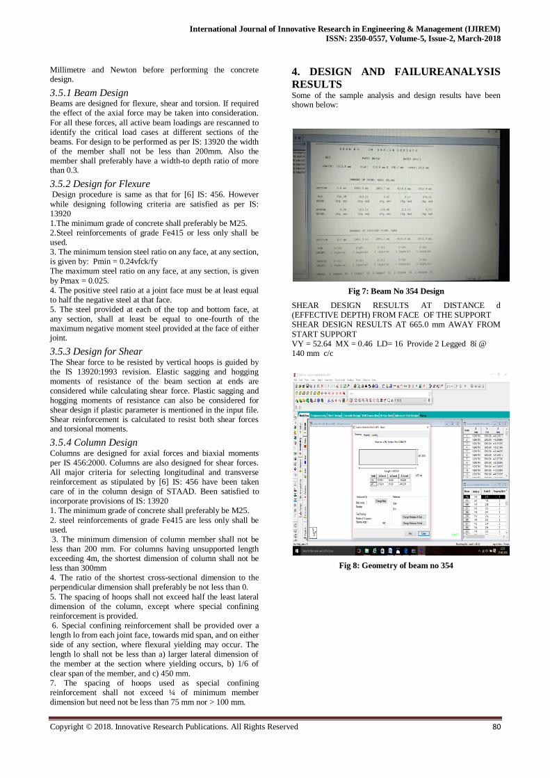
Fig 7: Beam No 354 Design
SHEAR DESIGN RESULTS AT DISTANCE d (EFFECTIVE DEPTH) FROM FACE OF THE SUPPORT SHEAR DESIGN RESULTS AT 665.0 mm AWAY FROM
START SUPPORT VY = 52.64 MX = 0.46 LD= 16 Provide 2 Legged 8í @ 140 mm c/c
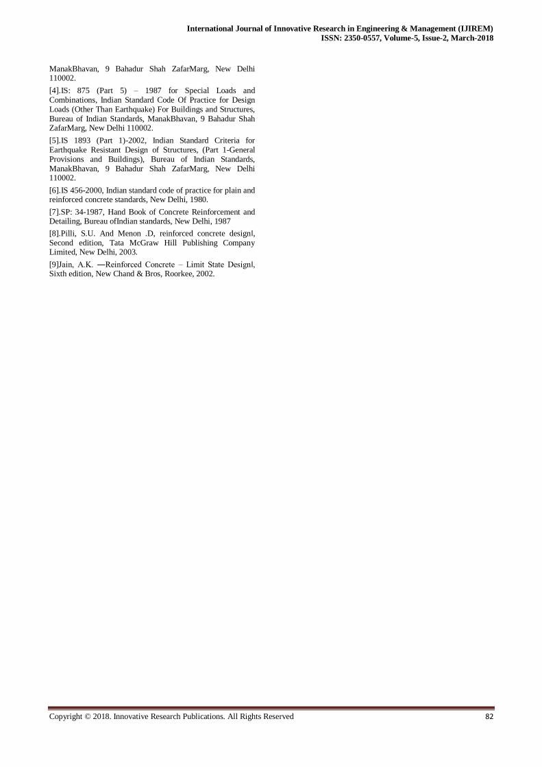
Fig 8: Geometry of beam no 354

Failure Analysis & Design of 500 Bedded Ladies Hostel at Cutm, Bhubaneswar
Copyright © 2018. Innovative Research Publications. All Rights Reserved 81
Fig 9: Bending moment along z direction
Fig 10: Stress at any section
Fig 11: No of Beam Failure
Fig 12: No Of Column Failure
Fig 13: Failure Due to Live Load
5. CONCLUSION This project is mainly concentrated with the failure analysis and design of multi-storied residential building with all possible cases of the loadings using STAAD. Pro. Due to changes in properties and loading system the members of the structure may be failed.
REFERNCES
[1].IS: 875 (Part 1) – 1987 for Dead Loads, Indian Standard Code Of Practice for Design Loads (Other Than Earthquake) For Buildings and Structures, Bureau of Indian Standards, ManakBhavan, 9 Bahadur Shah ZafarMarg, New Delhi 1100 02.
[2].IS: 875 (Part 2) – 1987 for Imposed Loads, Indian Standard Code Of Practice for Design Loads (Other Than Earthquake) For Buildings and Structures, Bureau of Indian Standards, ManakBhavan, 9 Bahadur Shah ZafarMarg, New Delhi 110002.
[3].IS: 875 (Part 3) – 1987 for Wind Loads, Indian Standard Code Of Practice for Design Loads (Other Than Earthquake) For Buildings And Structures, Bureau of Indian Standards,
0
20
40
60
80
100
120
fc20
fe415
fc15
fe415
fc15
fe250
fc20
fe250
No Of
Beam
Failure
Strength Of Beam
FAILURE OF BEAM
0
10
20
30
40
50
60
70
80
fc20
fe415
fc15
fe415
fc15
fe250
fc20
fe250
No Of
Column
Failure
Strength Of Column
FAILURE OF COLUMN
0
5
10
15
20
25
30
-5 0 -15 -20 -25
No Of
Member
Live Load Intensity
FAILURE DUE TO LIVE LOAD
International Journal of Innovative Research in Engineering & Management (IJIREM)
ISSN: 2350-0557, Volume-5, Issue-2, March-2018
Copyright © 2018. Innovative Research Publications. All Rights Reserved 82
ManakBhavan, 9 Bahadur Shah ZafarMarg, New Delhi 110002.
[4].IS: 875 (Part 5) – 1987 for Special Loads and Combinations, Indian Standard Code Of Practice for Design Loads (Other Than Earthquake) For Buildings and Structures, Bureau of Indian Standards, ManakBhavan, 9 Bahadur Shah ZafarMarg, New Delhi 110002.
[5].IS 1893 (Part 1)-2002, Indian Standard Criteria for Earthquake Resistant Design of Structures, (Part 1-General Provisions and Buildings), Bureau of Indian Standards, ManakBhavan, 9 Bahadur Shah ZafarMarg, New Delhi 110002.
[6].IS 456-2000, Indian standard code of practice for plain and reinforced concrete standards, New Delhi, 1980.
[7].SP: 34-1987, Hand Book of Concrete Reinforcement and Detailing, Bureau ofIndian standards, New Delhi, 1987
[8].Pilli, S.U. And Menon .D, reinforced concrete design‖, Second edition, Tata McGraw Hill Publishing Company Limited, New Delhi, 2003.
[9]Jain, A.K. ―Reinforced Concrete – Limit State Design‖, Sixth edition, New Chand & Bros, Roorkee, 2002.