STAAD Pro V8i
140
STAAD.Pro V8i (SELECTseries 3) Release Report 20.07.08 DAA039020-1/0002 Last updated: 10 October 2011
-
Upload
vivek-gosavi -
Category
Documents
-
view
251 -
download
8
description
Guide
Transcript of STAAD Pro V8i

STAAD.Pro
V8i (SELECTseries 3)
Release Report 20.07.08
DAA039020-1/0002Last updated: 10 October 2011


Copyright InformationTRADEMARK NOTICE
Bentley, the "B" Bentley logo, STAAD.Pro are registered or nonregistered trademarks of BentleySytems, Inc. or Bentley Software, Inc. All other marks are the property of their respective owners.
COPYRIGHT NOTICE© 2011, Bentley Systems, Incorporated. All Rights Reserved.
Including software, file formats, and audiovisual displays; may only be used pursuant to applicablesoftware license agreement; contains confidential and proprietary information of Bentley Systems,Incorporated and/or third parties which is protected by copyright and trade secret law and maynot be provided or otherwise made available without proper authorization.
AcknowledgmentsWindows, Vista, SQL Server, MSDE, .NET, DirectX are registered trademarks of MicrosoftCorporation.
Adobe, the Adobe logo, Acrobat, the Acrobat logo are registered trademarks of Adobe SystemsIncorporated.
RESTRICTED RIGHTS LEGENDSIf this software is acquired for or on behalf of the United States of America, its agencies and/orinstrumentalities ("U.S. Government"), it is provided with restricted rights. This software andaccompanying documentation are "commercial computer software" and "commercial computersoftware documentation," respectively, pursuant to 48 C.F.R. 12.212 and 227.7202, and "restrictedcomputer software" pursuant to 48 C.F.R. 52.227-19(a), as applicable. Use, modification,reproduction, release, performance, display or disclosure of this software and accompanyingdocumentation by the U.S. Government are subject to restrictions as set forth in this Agreementand pursuant to 48 C.F.R. 12.212, 52.227-19, 227.7202, and 1852.227-86, as applicable.Contractor/Manufacturer is Bentley Systems, Incorporated, 685 Stockton Drive, Exton, PA 19341-0678.
Unpublished - rights reserved under the Copyright Laws of the United States and Internationaltreaties.
END USER LICENSE AGREEMENTTo view the End User License Agreement for this product, review: eula_en.pdf.
Release Report 20.07.08 — i


Table of Contents
Section 1 STAAD.Pro V8i (SELECTseries 3) vIntroduction v
AD.2007-08.1 Features Affecting the General Program v
AD.2007-08.2 Features Affecting the Pre-Processor x
AD.2007-08.3 Features Affecting the Analysis and Design Engine xvi
AD.2007-08.4 Features Affecting Post Processing xxii
Section 2 STAAD.Pro V8i (SELECTseries 2) 1Introduction 1
AD.2007-07.1 Features Affecting the General Program 1
AD.2007-07.2 Features Affecting the Analysis and Design Engine 4
AD.2007-07.3 Features Affecting Post Processing 23
AD.2007-07.3.2 RC Designer 24
AD.2007-07.4 Additional Features 31
Section 3 STAAD.Pro V8i (SELECTseries 1) 33Introduction 33
AD.2007-06.1 Features Affecting the General Program 33
AD.2007-06.2 Features Affecting the Analysis and Design Engine 37
AD.2007-06.3 Features Affecting the RAM Connection Design Mode 54
AD.2007-06.4 Features Affecting the Piping Mode 55
Section 4 STAAD.Pro V8i 61Introduction 61
AD.2007-05.1 Features Affecting the Analysis and Design Engine 61
AD.2007-05.1.1 Geometric Nonlinear Analysis 62
AD.2007-05.1.2 IS 800:2007 65
AD.2007-05.1.3 Eurocode 3 Includes National Annex 70
AD.2007-05.1.4 Eurocode 8 72
AD.2007-05.1.5 AIJ Concrete Design Update 77
AD.2007-05.2 Features Affecting the Concrete Design Mode 77
AD.2007-05.2.1 RC Designer Member and Envelope Import 78
Section 5 STAAD.Pro V8i(release 20.07.04) 79
Release Report 20.07.08 — iii

Introduction 79
AD.V8i.0 New Features Affecting the General Program 79
AD.V8i.0 New Features Affecting the General Program 80
AD.V8i.0 New Features Affecting the General Program 87
AD.V8i.1 Features Affecting the Pre-Processor (Modeling Mode) 91
AD.V8i.1 Features Affecting the Pre-Processor (Modeling Mode) 91
AD.V8i.1 Features Affecting the Pre-Processor (Modeling Mode) 92
AD.V8i.1 Features Affecting the Pre-Processor (Modeling Mode) 95
AD.V8i.1 Features Affecting the Pre-Processor (Modeling Mode) 97
AD.V8i.2 Features Affecting the Analysis and Design Engine 98
AD.V8i.2 Features Affecting the Analysis and Design Engine 98
AD.V8i.2 Features Affecting the Analysis and Design Engine 99
AD.V8i.2 Features Affecting the Analysis and Design Engine 102
AD.V8i.3 Features Affecting the Post-Processing (Results Mode) 103
AD.V8i.3 Features Affecting the Post-Processing (Results Mode) 103
AD.V8i.3 Features Affecting the Post-Processing (Results Mode) 104
Technical Support 109
Index 111
iv — STAAD.Pro V8i (SELECTseries 3)

STAAD.Pro V8i What's New in Release 20.07.05 – v
Section 1
STAAD.Pro V8i (SELECTseries 3)
IntroductionThe Software Release Report for STAAD.Pro V8i SELECTseries 3 contains detailed information onadditions and changes that have been implemented since the release of STAAD.Pro V8i SELECTseries 2(release 20.07.07) This document should be read in conjunction with all other STAAD.Pro manuals,including the Revision History document.
AD.2007-08.1 Features Affecting the General Program
This section describes features that have been added that affect the general behavior of the STAAD.Proapplication.
AD.2007-08.1.1 ISM Integration
STAAD.Pro is now capable of transferring data to and from Bentley's Integrated Structural Modelingtechnology by means of the StructLink utility.

vi – STAAD.Pro V8i What's New in Release 20.07.05
What is ISM?
Bentley’s Integrated Structural Modeling (ISM) is a technology for sharing structural engineering projectinformation among structural modeling, analysis, design, drafting and detailing applications. ISM issimilar to Building Information Modeling (BIM), but focuses on the information that is important in thedesign, construction and modification of the load bearing components of buildings, bridges and otherstructures.
Purpose
There are two related purposes for ISM:
1. The transfer of structural information between applications.
2. The coordination of structural information between applications.
To provide for the first purpose (transferring information), ISM provides a means of defining, storing,reading and querying ISM Repositories.
To provide for the second purpose (coordination of information), ISM additionally provides capabilities todetect differences between ISM Repositories and to selectively (based on user selection) update either anISM Repository or an application’s data to provide a user-controlled level of consistency between the twodata sets.
ISM and Application Data
ISM is not intended to store all of the information that all of its client applications contain. Rather, it isintended to store and communicate a consensus view of data that is common to two or more of its clientapplications, such as STAAD.Pro.
The client application continues to hold and maintain its own private copy of project data. Some of theapplication data will duplicate that of the associated ISM Repository. The application data may evenconflict with that in the ISM Repository. The client application (or you as its user) may decide that aconflict gives the best data for client application’s and ISM’s different uses.
The program provided by ISM for accepting or rejecting model data changes is called StructuralSynchronizer. Structural Synchronizer provides you with a powerful set of tools for moving data betweenthe applications used in your workflow. Even relatively small structural models have enormous amounts ofdata and ISM allows you to re-use this data with ease. Care must be taken that only the data you wanttransferred between applications is sent, though.
When accepting changes made by client applications to an ISM Repository, some attention must be paidto changes are actually being made. A small change in a client application can have unintendedrepercussions if accepted. A repository is intended to represent the data that is common to the clientapplications. Some client application models will use only a subset of the repository data but changesmade to them can affect the entire repository if these changes are accepted when a repository updateaction is performed.
Let's take a look at an extended example of a multi-story, concrete building with a post-tensioned slabs:

STAAD.Pro V8i What's New in Release 20.07.05 – vii
l The architect on the project sends a Revit® model of the building to the structural engineer. FromRevit®, an ISM Repository is created. The lateral structure will be analyzed and designed using RAMElements while RAM Concept will be used to design the slabs.
l The engineer imports the floor and roof slabs into multiple RAM Concept files (each file representsone slab). The 5000 psi (35 MPa) concrete mix used for the slabs at all levels is found to be inad-equate for the roof slab. The roof slab is changed to use a 6000 psi (40 MPa) concrete mix.
l An update to the repository from RAM Concept is performed from the roof-level Concept file. ISMdetects the addition of the 6000 psi (40 MPa) mix, the removal of the 5000 psi (35 MPa) mix, andthe change in the setting of the roof slab material.
l An inspection of the change management Differencing Window will reveal the material propertiesof all of the slabs (on other levels) that used the 5000 psi (35 MPa) mix have been cleared. RAM Con-cept’s deletion of the 5000 psi (35 MPa) mix is correct in the scope of the roof slab, but this is caus-ing unexpected changes elsewhere.
l These were not the intended changes the engineer wished to make. To cause the correct changes tobe made, the engineer must reject the deletion of the 5000 psi (35 MPa) mix and reject the materialproperty changes in all of the slabs except the one at the roof level.
Overview of Sync ISM tools
A client application can send structural data to and from an ISM Repository through a set of Sync ISMtools. These tools allow you to both create and update client application models as well as ISMrepositories. Further, these flexible tools allow you to begin models and move data as your workflowdictates.
These tools are accessed by a sub-menu item found in ISM supported client applications.
When any of these tools are selected, the corresponding Windows Open or Save dialog box opens to selectan ISM repository for use. The Change Management environment is used with the update tools tocoordinate which changes are to be reflected in the models and repository.
You may review the history of changes made to an ISM Repository by using the View Repository Historytool. This tool also allows you to undo any changes made to a repository file.
Hint: It is recommend that you save your client application file before and after performing any SyncISM operation.
If you need to … … use this tool Description
Create a new ISM Repository froman existing client application model Create to
Repository
Transfers the currentmodel opened inclient application andgenerates a new ISMRepository. This is themost common way inwhich an ISM Repos-itory is initially
Sync ISM Tools in File > ISM submenu

viii – STAAD.Pro V8i What's New in Release 20.07.05
If you need to … … use this tool Description
created.
Create a new client applicationmodel from an existing ISM Repos-itory
New fromRepository
Creates a new clientapplication modelfrom an existing ISMRepository. This isused to transfer modeldata into other toolsused for your work-flow.
Update an existing repository toreflect changes made in a clientapplication model
Update toRepository
Coordinates changesmade to the model inthe client applicationand coordinate someor all of those changeswith an existing ISMRepository.
Update an existing client appli-cation model to reflect changes inan ISM Repository
Update fromRepository
Updates your clientapplication's modelwith some or all of thechanges which havebeen made to the ISMRepository.
AD.2007-08.1.2 Export to SACS
A new macro is included with STAAD.Pro which is used to export the current STAAD.Pro model to aSACS model, which can be opened in the SACS system Interactive Modeling program.
(Structural Analysis Computer System) is a finite element structural analysis suite of programs for theoffshore and civil engineering industries.
Exporting a STAAD model to a SACS input file
1. Open a input file in STAAD.Pro.
2. Select either
Tools > User Tools > STAAD to SACS Export
or
STAAD to SACS Export from the User Tools tool drop-down menu.
The Export STAAD Model to SACS dialog box opens.

STAAD.Pro V8i What's New in Release 20.07.05 – ix
Export STAAD Model to SACS dialog box
3. Type a file path and file name for the SACS Model file (file extension .INP) to which you want toexport the STAAD.Pro model data.
Hint: Click […] to open a Windows Save As… dialog box.
4. (Optional) Type a Title to use for the model in SACS.
5. Click OK.
A confirmation dialog box opens with the status of the export.
AD.2007-08.1.5 European Cold Formed Sections per EN10219-2
Sections defined in the publication, EN10219-2:1997 Cold formed welded structural hollow sections of non-alloy and fine grained structural steel. Part 2: Tolerances, dimensions and sectional properties have beenadded to library of cross sections available in the program.
The following section profiles are included as separate tables in the program:
l Table 6: Circular Hollow Sections (CHS)
l Table 7: Square Hollow Sections (SHS)
l Table 8: Rectangular Hollow Sections (RHS)
Specifying a European cold formed section
1. Select the General | Property page.
The Properties - Whole Structure dialog box opens.
2. In the Properties - Whole Structure dialog box, click Section Database.
The Section Profile Tables dialog box opens.
3. Select the Coldformed Steel tab.
4. Select one of the tables available in the European Cold Formed section.
5. Select an entry from the Select Profile list.

x – STAAD.Pro V8i What's New in Release 20.07.05
6. Click Add.
The section is now added to the Section tab in the Properties - Whole Structure dialog box and canbe assigned to members..
AD.2007-08.1.6 Japanese JIS Hollow Sections
The catalog of available Japanese hot rolled steel sections has been expanded to include the hollowsections from JIS publications.
l JIS G3444:2005 Design Standard for Steel Structures - Based on Allowable Stress Concept definesproperties for circular hollow sections and are classed as ‘General pipe sections’. The existing PIPEtable has been updated to ensure that it is consistent with this table.
l JIS G3475:2005 Design Standard for Steel Structures - Based on Allowable Stress Concept definesproperties for circular hollow sections and are classed as ‘Architectural pipe sections’. A new tablefor these Circular Hollow (CHS) will be added.
l JIS G3466:2005 Design Standard for Steel Structures - Based on Allowable Stress Concept definesproperties for square and rectangular hollow sections. These will be added to the existing JapaneseSections database as two new tables: Rectangular Hollow (RHS) and Square Hollow (SHS)
Refer to Section 12C.4 of the International Design Codes manual for additional details on using the Built-in Japanese Steel Section Library.
Specifying a Japanese hollow section
1. Select the General | Property page.
The Properties - Whole Structure dialog box opens.
2. In the Properties - Whole Structure dialog box, click Section Database.
The Section Profile Tables dialog box opens.
3. Select the Steel tab.
4. Select one of the tables available in the Japanese section: Pipe, Rectangular Hollow, Square Hollow,or Circular Hollow.
5. Select an entry from the Select Profile list.
6. Click Add.
The section is now added to the Section tab in the Properties - Whole Structure dialog box and canbe assigned to members..
AD.2007-08.2 Features Affecting the Pre-ProcessorThis section describes features that have been added that affect the pre-processor section of the program,also known as the Modeling Mode.
STAAD.Pro V8i What's New in Release 20.07.05 – xi
AD.2007-08.2.1 Wind Load Generation per ASCE 7-10
Wind loads intensity values may now be automatically generated per the 2010 edition of SEI/ASCE 7 usingthe ASCE-7: Wind Load dialog in the user interface. This dialog allows you to generate a wind loadingpattern based on the parameters used in this specification.
The primary change in wind load evaluation between the 2002 and 2010 editions of the ASCE 7specification involve the method of calculating the force coefficient, Cf, for solid freestanding walls andsolid signs. The formula provided in the commentary related to Figure 6-20 in the specification is used:
Cf = {1.563 + 0.008542ln(x) - 0.06148·y + 0.009011[ln(x)]2 - 0.2603·y2 - 0.08393·yln(x)}/0.85
Where:
x = B/s
y = s/h
Generating a wind load intensity per ASCE 7-10
1. Add a wind load definition to the model.
2. Select this definition in the Load & Definition dialog box and click Add.
The Add New: Wind Definition dialog box opens.
3. On the Intensity tab, select the as Custom in the drop-down list and click Calculate as per ASCE-7.
The ASCE-7: Wind Load dialog box opens.
4. On the Common Data tab, select 2010 as the ASCE 7 - edition.
5. Specify or set the parameters needed to define the load.
Click Apply prior to selecting a different dialog tab to update the dialog for the specifiedparameters.
6. Click OK.
AD.2007-08.2.2 Single Mass Model
A new load type, mass, is available for reference load cases. This is used to create a single mass model forall dynamic loads (i.e., seismic, response spectrum, time history, etc.). This load case can be used forseismic loads in lieu of a weight table, reducing repetitive data entry for analysis methods which wouldrequire the same data.
Refer to Section 5.31.6 of the Technical Reference manual for additional details.
Adding a mass model reference load
A mass model reference load is added in the same way as any other reference load, but with the LoadingType set to Mass.

xii – STAAD.Pro V8i What's New in Release 20.07.05
1. Either
select Commands > Loads > Definitions > Reference Load
or
select the Definitions > Reference Load Definitions section of the Load & Definition dialog boxand click Add.
The Add New: Reference Load Definition dialog box opens.
2. (Optional) Type a reference load identification number in the Number field.
Hint: This number is incremented by one from any previously defined reference loads andtypically does not need to be changed.
3. Select Mass as the Loading Type.
4. (Optional) Type a label in the Title field.
For example, you may want to label the reference by typing Mass Model.
5. Click Add.
The dialog box closes and a new reference load definition is added to the input file.
Adding mass loads to the mass model reference load
1. Select the mass Reference Load Case in the Load & Definition dialog box.
2. Click Add.
The Add New: Reference Load Items dialog box opens.
3. Select the type of load you want to add from the tree.
4. Specify load parameters (e.g., magnitude, direction, etc.).
5. Click Add.
6. Repeat steps 3 through 5 to add additional loads.
7. Click Close.
Using the mass model reference load in a seismic load
1. Select a previously defined Seismic Definition in the Load & Definition dialog box.
2. Click Add.
The Add New: Seismic Definitions dialog box opens.
3. Select the Reference Load leaf on the left panel.
4. Select the Reference Load case in the Available Load Cases list and click >.
5. Click Add.
6. Click Close.

STAAD.Pro V8i What's New in Release 20.07.05 – xiii
AD.2007-08.2.1 Eurocode Load Combination Generator
A new macro has been included with the program to generate load combinations for the Strength limitstate per Eurocode – Basis of structural design, BS EN 1990:2002+A1:2005.
The load combination generator is capable of creating load combinations per equations 6.10, 6.10a, or 6.10bfound in Cl. 6.4.3.2.
These equations specify the following combinations of loads:
γ G γ P γ Q γ ψ Q+ + +j G j k j p Q k i Q k≥ 1 , , , 1 , 1 > 1 , 1 0, 1 , 1Σ Σ
(6.10)
Alternatively, for the strength limit state, the less favorable of equations 6.10a and 6.10b may be used:
γ G γ P γ ψ Q γ ψ Q+ + +j G j k j p Q k i Q k≥ 1 , , , 1 0, 1 , 1 > 1 , 1 0, 1 , 1Σ Σ
(6.10a)
ξ γ G γ P γ Q γ ψ Q+ + +j
j G j k j p Q k i Q k≥ 1 , , , 1 , 1 > 1 , 1 0, 1 , 1Σ Σ
(6.10b)
Where:
Gk = Permanant actionsP = Prestress actionsQk = Variable actions
Note: The effects in each of the above equations are always additive. If any effect is negative (that is,would reduce the final sum), its effect is taken as zero.
Generating load combinations per Eurocode 0
1. Open a input file in STAAD.Pro.
2. Select either
Tools > User Tools > Euro Code Load Combination Generator
or
Euro Code Load Combination Generator from the User Tools tool drop-down menu.
The Eurocode Combination Generator dialog box opens.
Eurocode Combination Generator dialog box

xiv – STAAD.Pro V8i What's New in Release 20.07.05
3. Select the Equation Number to use for the generation of load combinations.
4. (Optional) Specify a Start Combination Number.
5. (Optional) Specify load Factors for use in the combination equations.
Factor title Equation notation
Permanent Actions, Gamma G γG
Pre Stress Actions, Gamma P γP
Variable Actions, Gamma Q γQ
Permanent Action Reduction Factor, Xi ξ
Variable Action Combination Factor, Psi 0 ψ0
Note: The default values are taken from those provided in EC0.

STAAD.Pro V8i What's New in Release 20.07.05 – xv
6. (Optional) Click Table A1.1 to select one of the recommended values for the Permanent ActionReduction Factor, Psi (ψ0).
7. Click Categories to specify in which load action classification each STAAD.Pro load category is tobe assigned.
Action Included Loads
(None) Loads of this type will not be included in generated load com-binations.
Permanent Gk (permanent) By default, Dead loads are included.
Hint: You may also want to include Mass or Gravity load.
Variable Q (variable) By default, Live, Roof Live, Wind, and Snow areincluded.
Hint: You may also want to include loads such as Seismic,Temperature, etc.
Pre Stress P (prestress) No loads are included by default in this category.
Hint: As STAAD.Pro does not use a load category forprestressing forces, a less-common load category such asImperfection can be used for this action.
8. Click Generate Combinations.
A confirmation dialog box opens with the status of the export. Load cases are generated with theselection equation and load case number in the title.
AD.2007-08.2.4 Rigid Floor Diaphragms
A new feature has been added to easily model a rigid floor diaphragm without the need to specify amaster joint at each. When specified, this command directs the engine to perform the following:
a. calculate the center of mass for each rigid diaphragm (where master joint is to be located)considering the mass model of the structure. The mass must be modeled using the new massreference load feature.
b. create, internally, an analytical node at the center of mass location to be included during analysis(unless a master node is specified) if an existing analytical node exists at this point, then theexisting joint is used in lieu of creating a new joint.
c. search all nodes available within a diaphragm and add them as slave nodes; with the master nodelocated at the center of mass for the diaphragm (or at the specified master node)
Refer to Section 5.28.2 of the Technical Reference manual for additional details.

xvi – STAAD.Pro V8i What's New in Release 20.07.05
AD.2007-08.3 Features Affecting the Analysis and Design Engine
The following section describes the new features that have been added to the analysis and design engineand existing features that have been updated or modified.
AD.2007-08.3.1 API 2A WSD 21st Ed. Update
Joint checking for tubular members per the American Petroleum Institute 2A-WSD code has beenupdated to the 21st Edition (December 2000) of that code, including errata and supplements 1 to 3 (latest:Supplement 3 - March 2008). Additionally, the process of joint design has been simplified.
Note: Only simple joints and overlapping joints will be considered by the program. Other type such asgrouted joints, joints with ring stiffeners etc are not be considered.
The clauses/sections in the API code that have been dealt with are:
l 4.2.1 Material strength
l 4.2.3 Minimum Capacity
l 4.2.4 Joint Classification
l 4.3 Simple joints
l 4.4 Overlapping joints
Refer to Section 22 of the International Design Codes manual for additional information on themethodology used.
External Joint Data File
In previous versions, the LEG design parameter was used to direct the program to generate a separate jointdata file or to check a user-specified file. This file is now automatically generated or checked as needed.
As the API code allows for mixed joint types, the PUNCH column in the input file has been replaced withK, X, and Y columns which are used to designate fractional contributions of each joint class. Similarly,overlapping joints are indicated by using a negative value for the GAP between braces and the membernumber of the overlapping member in the OB column (replaces THETAT used in previous versions).
If the FILENAME.PUN file is not detected in the same folder as the current STAAD input file (where"FILENAME" is the same as the .STD file), then the program assumes this is the initial joint design and thisfile is created. If, however, this file is detected, the program assumes that the that the joint design hasbeen performed at least once and will use this file to perform the joint checks.

STAAD.Pro V8i What's New in Release 20.07.05 – xvii
Checking tubular member joints per API
The checking of joints is an iterative process done by means of an automatically generated text file.
1. Model a structure as you normally would.
Note: Only circular pipe members are considered.
Hint: Using TRUSS specifications helps to reduce analysis time.
2. In the Steel Design - Whole Structure dialog box, select API as the design code.
3. (Optional) Specify the factor of safety used for joint checks using the new FSJ design parameter.
4. (Optional) Specify all other necessary design parameters.
The LEG parameter is no longer used to generate or check joint data files.
5. Specify CODE CHECK or SELECT MEMBER commands as needed and perform the analysis.
If this the FILENAME.PUN file is not detected in the same folder as the input file, the programassumes this is the first time the structure is being analyzed and generates this input file withdefault data for the detected joints. Each joint is assumed to be a Y joint by default.
6. Modify the default joint data in the FILENAME.PUN as needed to describe the actual jointconditions.
A text editor can be used to make changes to this file. Be sure to save changes once complete.
7. Re-analyze the STAAD input file.
Joint check results follow the steel design output.
8. Repeat steps 3 through 7 as needed to make changes in the structure.
AD.2007-08.3.2 Shear Buckling per EC3
The design code checks performed per Eurocode 3 have been updated to include checks for shear bucklingin I Sections and PFC Sections. Eurocode 3 – Part 1 (EN 1993-1-1:2005) states in Cl.6.2.6 that the checks forShear buckling are to be based on the procedure in EN 1993-1-5. STAAD.Pro performs checks based on themethods Section 5 of EN 1993-1-5:2006.
In the case of an unstiffened web, the program will check the unstiffened web capacity. If the demand dueto applied loads is greater than this capacity, the program will calculate a suitable spacing for transversestiffener plates in order to meet the demand.
In the case of a web with transverse stiffeners, the program will check the capacity of the web consideringthe provided stiffener spacing. The program will consider both the buckling capacity of the web as well asthe flange. If the demand due to applied loads is greater than this capacity, the program will calculate areduced stiffener spacing for transverse stiffener plates in order to meet the demand.
Note: Only transverse stiffeners are taken into account. The effect of any longitudinal stiffeners isignored.

xviii – STAAD.Pro V8i What's New in Release 20.07.05
The distance between transverse stiffeners is specified by the STIFF parameter, in the current units oflength. If no value is specified, the program assumes a spacing equal to either the member length or depthof beam, whichever is greater.
The output file provides recommendations on the evaluation of stiffeners (e.g., adding stiffeners at aspacing or increasing the web thickness).
Refer to Section 7C.5.3 of the International Design Codes manual for additional information.
AD.2007-08.3.3 IS800:2007 Working Stress Method
The IS:800-2007 Steel code was deviated in concept from its -1984 version (based on Working StressMethod) and introduced the Limit State Method of Design. The entire 2007 version of the code is devotedto the Limit State Method of Design, except Chapter 11. This Chapter comprises of a couple of pages andhas the guideline for the Design of Steel sections as per working stress method (WSM). The approach ofthis new working stress method is different from its earlier version and utilizes the concept of SectionSlenderness and Section Classification.
At the time of first implementation of this code in STAAD.Pro, the working stress method was kept out-of-scope as the primary need of the industry was the Limit State Method. However, with the time, thedemand of the working stress method gradually increases. Some of the design sectors, more specificallythe PEB Industry, use WSM widely. To cater the needs of the industry, it was later decided by theProduct Management Team to include WSM of IS:800-2007 in STAAD.Pro.
The program now includes design per the Working Stress Method (WSM) methodology in addition toLimit State method for design of steel structures per IS800:2007.
Some minor corrections to the Limit State Design option have also been made.
Specifying a design using IS 800:2007 Working Stress Method
1. In the Modeling mode, select the Design | Steel tab.
The Steel Design - Whole Structure dialog box opens.
2. In the Current Code drop-down menu, select IS800 2007 WSD.
3. Click Define Parameters….
The Design Parameters dialog box opens.
4. Click Add.
This will insert the following commands into the STAAD input file:
CODE IS800 WSD
AD.2007-08.3.4 Surface Element Selfweight
A new surface load has been added to include the self weight of surface elements. This command can beused to calculate and include the weight of surface elements in the analysis of a structure. The

STAAD.Pro V8i What's New in Release 20.07.05 – xix
Adding a surface selfweight load via the Graphical Interface
1. Select the General | Load & Definition page.
The Load & Definition dialog box opens.
2. Select the load case to which you wish to add a surface selfweight load by expanding the Load Casedetails entry.
3. Click Add.
The Add New: Load Items dialog box opens.
4. Select the Surface Loads > Selfweight Load tab.
5. (Optional) Select a Direction.
The global Y direction is the default.
6. (Optional) Type a load Factor.
7. Click Add.
The SSELFWT command, along with direction and factor, are added to the load case.
8. Assign the load as you would any other load item.
Refer to Section 5.32.9.2 of the Technical Reference Manual for additional details on theSSELFWEIGHT command.
AD.2008-06.2.3 Eurocode 3 National Annex
Two additional country's National Annex to Eurocode 3 have been incorporated into the Steel designmodule in STAAD.Pro: Singapore and Beglium. As with the other National Annexes to EC-3, thisimplementation will make use of the NA parameter.

xx – STAAD.Pro V8i What's New in Release 20.07.05
AD.2007-08.3.5.1 Belgian National Annex to Eurocode 3 (EN 1993-1-1:2005)
The Belgian National Annex document referred to is “NBN EN 1993-1-1:2005”.
When the Belgian National Annex to EC3 is used for design, the output section title is revised to includethe Belgian National Annex (National Annex to NBN-EN 1993-1-1). Additionally, the partial safety factorsused are included in the output and are as specified in the Belgian NA. The value for C1 and k factors usedin the calculation of the elastic critical moment are also included in the report.
Note: For additional information, please refer to Section 7D.10 and Section 7C. of the InternationalDesign Codes manual.
Specifying a design using the Belgian NA to EC3
1. In the Modeling mode, select the Design | Steel tab.
The Steel Design - Whole Structure dialog box opens.
2. In the Current Code drop-down menu, select EN 1993-1-1:2005.
3. Click Define Parameters….
The Design Parameters dialog box opens.
4. Select the NA parameter in the list box.
5. Select the option for (8) Belgium.
6. Click Add.
This will insert the following commands into the STAAD input file:

STAAD.Pro V8i What's New in Release 20.07.05 – xxi
CODE EN 1993-1-1:2005
NA 8
AD.2007-08.3.5.2 Singaporean National Annex to Eurocode 3 (EN 1993-1-1:2005)
The Singaporean National Annex document referred to is “SS EN 1993-1-1:2005”.
When the Singaporean National Annex to EC3 is used for design, the output section title is revised toinclude the Singaporean National Annex (National Annex to SS-EN 1993-1-1). Additionally, the partialsafety factors used are included in the output and are as specified in the Singaporean NA. The value for C1and k factors used in the calculation of the elastic critical moment are also included in the report.
Note: For additional information, please refer to Section 7D.9 and Section 7C. of the InternationalDesign Codes manual.
Specifying a design using the Belgium NA to EC3
1. In the Modeling mode, select the Design | Steel tab.
The Steel Design - Whole Structure dialog box opens.
2. In the Current Code drop-down menu, select EN 1993-1-1:2005.
3. Click Define Parameters….
The Design Parameters dialog box opens.
4. Select the NA parameter in the list box.
5. Select the option for (7) Singapore.
6. Click Add.
This will insert the following commands into the STAAD input file:
CODE EN 1993-1-1:2005
NA 7
AD.2007-08.3.6 EC3 Slender Circular Hollow Sections
Slender circular hollow (pipe) sections may now be designed per Eurocode 3 (EN 1993-1-6:2007).
Eurocode 3 – Part 1 (EN 1993-1-1:2005)—hereafter EC3-6—states in Cl. 6.2.2.5 (5) that the design of slendercircular hollow sections is to be based on the procedure in EN 1993-1-6. EC3 6 deals with the design ofshell structures. EC3-6 does not, however, specify additional or modified safety factors. Therefore, thedefault safety factors from EN 1993-1-1 are used.
Note: You can change these values through the GM0, GM1, and GM2 design parameters.
The program checks the plastic and buckling limit states for primary stresses based on the stress designmethod described in EC3-6.
xxii – STAAD.Pro V8i What's New in Release 20.07.05
Refer to Section 7C.5.6 in the International Design Codes manual for details on the methodology andcalculations used in this design.
AD.2007-08.3.7 User Defined Section for EC3
The feature to design user-provided table (UPT) general sections has now been introduced steel membersdesigned per Eurocode 3 (EN 1993-1-1:2005). However, rather than assuming that the section will behavelike an I section, you are given the option of choosing the 'section-type' he would like to design themember for.
This is achieved through the introduction of a new design parameter, GST, that has the following values:
0. I-Section (Default)
1. Single Channel
2. Rectangular Hollow Section
3. Circular Hollow Section
4. Angle Section
5. Tee Section
Unless specified using the GST parameter, a general section will be assumed to be an I- Section.
Note: This parameter will be ignored if assigned to any section other than a General Section.
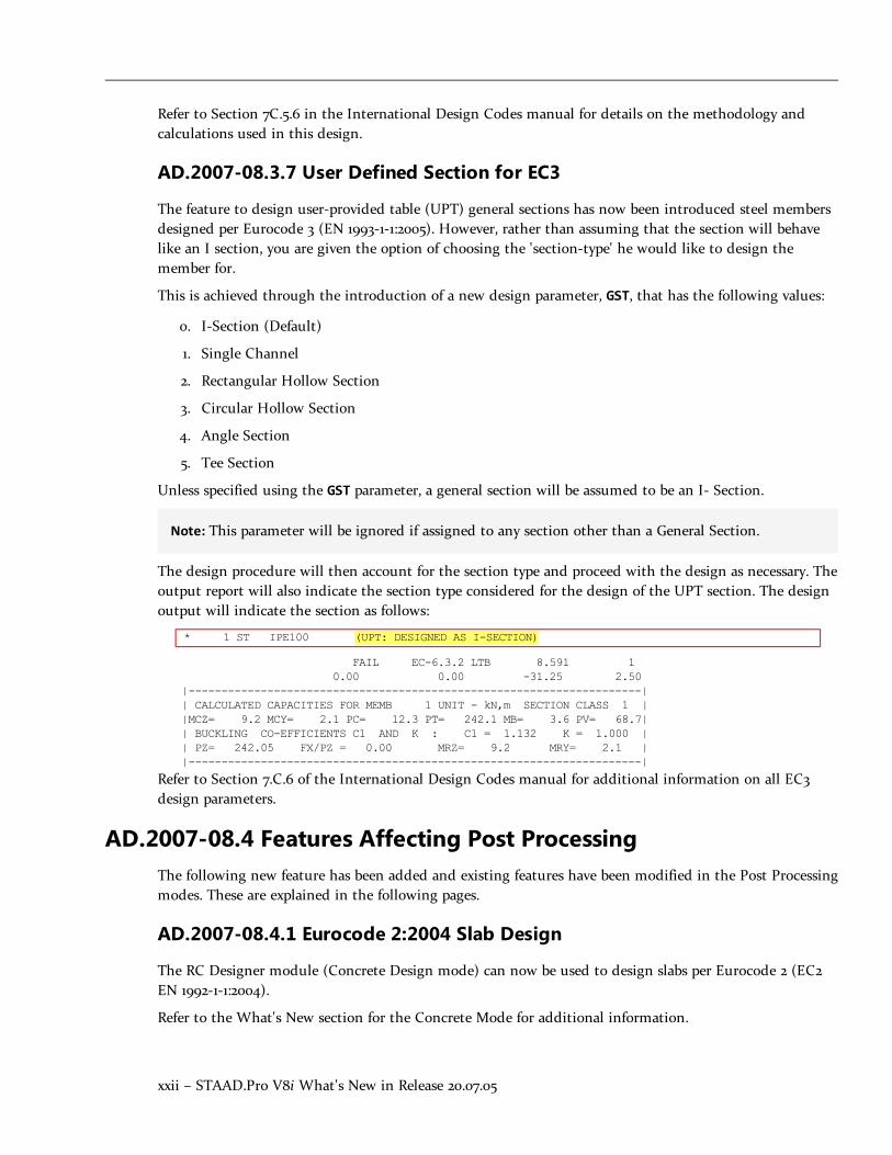
The design procedure will then account for the section type and proceed with the design as necessary. Theoutput report will also indicate the section type considered for the design of the UPT section. The designoutput will indicate the section as follows:
* 1 ST IPE100 (UPT: DESIGNED AS I-SECTION)
FAIL EC-6.3.2 LTB 8.591 10.00 0.00 -31.25 2.50
|---------------------------------------------------------------------|| CALCULATED CAPACITIES FOR MEMB 1 UNIT - kN,m SECTION CLASS 1 ||MCZ= 9.2 MCY= 2.1 PC= 12.3 PT= 242.1 MB= 3.6 PV= 68.7|| BUCKLING CO-EFFICIENTS C1 AND K : C1 = 1.132 K = 1.000 || PZ= 242.05 FX/PZ = 0.00 MRZ= 9.2 MRY= 2.1 ||---------------------------------------------------------------------|
Refer to Section 7.C.6 of the International Design Codes manual for additional information on all EC3design parameters.
AD.2007-08.4 Features Affecting Post ProcessingThe following new feature has been added and existing features have been modified in the Post Processingmodes. These are explained in the following pages.
AD.2007-08.4.1 Eurocode 2:2004 Slab Design
The RC Designer module (Concrete Design mode) can now be used to design slabs per Eurocode 2 (EC2EN 1992-1-1:2004).
Refer to the What's New section for the Concrete Mode for additional information.
STAAD.Pro V8i What's New in Release 20.07.05 – 1
Section 2
STAAD.Pro V8i (SELECTseries 2)
IntroductionThe Software Release Report for STAAD.Pro V8i (SELECTseries 2) contains detailed information onadditions and changes that have been implemented since the release of STAAD.Pro V8i (SELECTseries 1)(release 20.07.06) This document should be read in conjunction with all other STAAD.Pro manuals,including the Revision History document.
AD.2007-07.1 Features Affecting the General Program
This section describes features that have been added that affect the general behavior of the STAAD.Proapplication.

2 – STAAD.Pro V8i What's New in Release 20.07.05
AD.2007-07.1.1 Academic Licensing
In order to ensure that the next generation of engineer that emerges from the higher education system isup to speed using our applications, Bentley has a policy of providing software to Universities and Collegesat a favorable rate.
Students can now use STAAD.Pro under an Academic License, which is obtained through a SELECTaccount. Contact your regional engineer or visit Bentley.com to obtain a license.
Note:When using an Academic License, the program window title bar and About window indicatethis. Similarly, all output (Analysis files and Reports generated from STAAD.Pro) are marked as"Academic License User."
Warning: The Advanced Analysis Engine is not available when using the program under an AcademicLicence.
AD.2007-07.1.2 StructLink and PipeLink Plug-ins
Two plug-ins are available to you when installing STAAD.Pro V8i (SELECTseries 2): StructLink andPipeLink.
l StructLink is a utility used for the bi-direction exchange of data between STAAD.Pro and ProSteelV8i.
l PipeLink is an all new utility used for the exchange of pipe stress model data between STAAD.Proand AutoPIPE V8i. Refer to section AD.2007-07.3.4 for additional the bi-directional data exchangecapabilities made available through this utility.
Note: During the installation of STAAD.Pro V8i, select the option to install additional programs andutilities in order to have these two utilities installed.
Refer to the documentation included with these plug-ins for additional information on their use.
AD.2007-07.1.3 Structural Dashboard Integration
Bentley's Structural Dashboard is now integrated into STAAD.Pro V8i.
Description
Bentley's Structural Dashboard V8i is a free utility application which allows you to manage workflows andproject files as well as keep up to date with latest products, news, and Be Communities happenings. Thisprogram can now be accessed from within STAAD.Pro and will launch whenever STAAD.Pro is started toassist you in managing your entire project workflow.
When STAAD.Pro is first launched after installing Structural Dashboard, a welcome dialog opens to allowyou to set the automatic launch option. To launch the program and continue allowing it to launch

STAAD.Pro V8i What's New in Release 20.07.05 – 3
whenever a Bentley Structural program starts, leave the option selected and click the OK button.Otherwise, you can de-select this option before proceeding.
Launch Structural Dashboard on program startup
Set this option to open the Structural Dashboard application whenever STAAD.Pro is opened.
Hint: This setting can be changed at any time from within the Structural Dashboard program.
Show me this dialog on startup
Set this option to display this dialog whenever STAAD.Pro is opened.
Hint: This setting can be changed at any time from the Configure Program dialog File Optionstab.
> To launch Structural Dashboard from STAAD.Pro
1. Select File > Structural Dashboard….
The Bentley Structural Dashboard V8i program opens.

4 – STAAD.Pro V8i What's New in Release 20.07.05
Note: If Structural Dashboard has not been installed, this menu item is inactive. You candownload the program from http://www.bentley.com/en-US/Promo/ISM/downloads/.
Note: Refer to Section 2.3.1 of the User Interface Manual for additional help in using the StructuralDashboard with STAAD.Pro.
AD.2007-07.2 Features Affecting the Analysis and Design Engine
The following section describes the new features that have been added to the analysis and design engineand existing features that have been updated or modified.
Note: Items labelled with an asterisk (*) were added in the QA&R release of V8i (SELECTseries 2)(Build 20.07.07.31).

STAAD.Pro V8i What's New in Release 20.07.05 – 5
AD.2007-07.2.1 Time History Spectrum Enhancements
Purpose
New options have been added to the spectrum input for a Time History definition which allow you tooutput time history input data, a Response Spectrum for a Time History load, or to use frequency-spectrum pairs. These options can be added by modifying the input command file.
Description
Two new output options are available for reporting time history input and synthetic time history groundacceleration data used by the program for a time history load with the spectrum generation option. Youcan control the amount of output generated (as this can be quite large) as well.
A new option has also been added to allow you to instruct the program to use frequency-spectra pairs inlieu of period-spectra pairs for the time history spectrum input.
> To output time history data
1. Create a structure with a time history definition using the Spectrum function option, eitherthrough the STAAD.Pro Editor or the Graphical Interface.
2. Select the STAAD Editor tool from the File toolbar.
or
Select Edit > Edit Input Command File…
The STAAD Editor window opens.
3. After the DEFINE TIME HISTORY command, in the SPECTRUM options, add the command THPRINTf18.
Where f18 directs the program to output either the beginning and last 54 data points (f18 = 1) orthe entire curve (f18 = 2) or a select number of beginning and last data points (f18 ≥ 10).
4. Save the command input file and exit the STAAD Editor window to return to the STAAD.Prographical interface.
5. Run the analysis as you normally would.
The Spectrum Input Parameters are included in the STAAD Output (.ANL) file along with theTime History Output (limited to the f18 value specified).
> To generate spectrum output for a time history
1. Create a structure with a time history definition using the Spectrum function option, eitherthrough the STAAD.Pro Editor or the Graphical Interface.
2. Select the STAAD Editor tool from the File toolbar.
or
Select Edit > Edit Input Command File…

6 – STAAD.Pro V8i What's New in Release 20.07.05
The STAAD Editor window opens.
3. After the DEFINE TIME HISTORY command, in the SPECTRUM options, add the command SPRINTf19.
Where f19 represents an integer value after the SPRINT command to instruct the program to onlyoutput the beginning and last number of values equal to this integer.
4. Save the command input file and exit the STAAD Editor window to return to the STAAD.Prographical interface.
5. Run the analysis as you normally would.
A summary of the Spectrum input and the curve points are included in the STAAD Output (.ANL)file.
> To use the Frequency-Spectra pairs in a Time History load
1. Create a structure with a time history definition using the Spectrum function option, eitherthrough the STAAD.Pro Editor or the Graphical Interface.
2. Select the STAAD Editor tool from the File toolbar.
or
Select Edit > Edit Input Command File…
The STAAD Editor window opens.
3. After the DEFINE TIME HISTORY command, in the SPECTRUM options, add the command FREQ.
4. Save the command input file and exit the STAAD Editor window to return to the STAAD.Prographical interface.
5. Run the analysis as you normally would.
Note: Refer to Section 5.31.4 of the Technical Reference Manual for additional information on usingthe updated options-spec for the Spectrum input option.
AD.2007-07.2.2 Response Spectrum Signed Results and IMR Load Cases
Purpose
Two methods to produce signed response spectrum results have been added to the STAAD.Pro analysisengine. The Dominant and Sign commands may be used in the input file to produce signed output.Additionally, STAAD.Pro now includes an option to automatically generate new load cases based on aspecified number of modes from the response spectrum.
Signed Results
STAAD.Pro can now assign a mathematical sign (positive or negative) to the modal results by one of twomeans. The first method allows you to select a DOMINANT mode, the sign of which will then be appliedto all other modes. The second method will produce signed values for all results. The sum of squares of

STAAD.Pro V8i What's New in Release 20.07.05 – 7
positive values from the modes are compared to sum of squares of negative values from the modes. If thenegative values are larger, the result is given a negative sign.
Individual Modal Response Case Generation
The Individual Modal Response (IMR) load cases are simply the mode shape scaled to the magnitude thatthe mode has in this spectrum analysis case before it is combined with other modes. If the IMR parameteris entered, then STAAD will create load cases for the first specified number of modes for this responsespectrum case (i.e., if five is specified then five load cases are generated, one for each of the first fivemodes). Each case will be created in a form like any other primary load case.
The results from an IMR case can be viewed graphically or through the print facilities. Each mode cantherefore be assessed as to its significance to the results in various portions of the structure. Perhaps one ortwo modes could be used to design one area/floor and others elsewhere. You can use subsequent loadcases with Repeat Load combinations of these scaled modes and the static live and dead loads to formresults that are all with internally consistent signs (unlike the usual response spectrum solutions). Youcan also use the Repeat Load capability to combine the modal applied loads vector with the static loadingsand solve statically with P-Delta or tension only.
The modal accelerations are multiplied by the nodal masses to produce equivalent static lateral forces foreach modal load case.
Note:When the IMR option is entered for a Spectrum case, then a Perform Analysis & Change mustbe entered after each such Spectrum case.

8 – STAAD.Pro V8i What's New in Release 20.07.05
Figure - Updated Response Spectra dialog containing controls for generating signed results and IMR load cases

STAAD.Pro V8i What's New in Release 20.07.05 – 9
> To add Signed results to a Response Spectrum
1. Select Commands > Loading > Load Commands.
or
Select the General | Load & Definition page and then click the New… button.
The Create New Load Items dialog opens.
2. Select the Response Spectra tab.
3. Select the Code you wish to use.
Note: See below for using IMR generation options. All other parameters are same as previousversions.
4. Select the option to use the Dominant Mode No. to assign the same sign as the selected mode toall modes.
5. (Optional) Select to provide Signed results to
Note: Selecting this option will not use the Dominant Mode No., but rather will create signedvalues for all results by comparing the sum of the squares values for positive and negative valuesto determine the governing sign.
6. Click the Add button to add this response spectrum load.
> To add Individual Modal Response results to a Response Spectrum
1. Select Commands > Loading > Load Commands.
or
Select the General | Load & Definition page and then click the New… button.
The Create New Load Items dialog opens.
2. Select the Response Spectra tab.
3. Select the Code you wish to use.
Note: See above for options to add signed results. All other parameters are same as previousversions.
Note: The Individual Modal Response case generation is not available for SNiP II code responsespectra.
4. Select the option to Generate load cases for … to individual modal response load cases.
5. (Optional) Specify the number of modes for which load cases will be generated.

10 – STAAD.Pro V8i What's New in Release 20.07.05
Note: Selecting this option will not use the Dominant Mode No., but rather will create signedvalues for all results by comparing the sum of the squares values for positive and negative valuesto determine the governing sign.
6. (Optional) Specify a beginning load case number for the first primary load case generated from theIMR.
7. Click the Add button to add this response spectrum load.
Refer to section 5.32.10.1 of the Technical Reference Manual for additional information on the newparameters available to the SPECTRUM commands.
AD.2007-07.2.3 Design of Class 4 Steel Sections per S16-01
Purpose
An update to the Canadian Steel Design code has been added for the design of Class 4 (slender) steelsections per CAN/CSA-S16-01. Previous versions of STAAD.Pro were capable of designing Section Classes 1,2, or 3.
Description
The design of slender Class 4 steel sections does not require any different actions or input. The analysisengine will determine if a section meets the criteria for a Class 4 section and then perform the necessarychecks, if design checks have been requested for that member.
Methodology
Refer to Section 3B.6 "Member Resistances" of the International Codes Manual for a detailed description ofthe methodology used in STAAD.Pro for performing the design of Class 4 sections per S16-01. Averification problem using this feature has also been added to Section 3B.10.
AD.2007-07.2.4 Von Mises Stresses per AIJ 2002 and 2005
Purpose
Design per AIJ (Japanese) steel design codes has been updated to include checking members in accordancewith Von Mises stress criteria in AIJ 2005. This check is a requirement for the design of steel structures innuclear power plants in Japan.
Description
The von Mises stress equation is calculated when the new MISES parameter has been set to a value of 1 (thedefault value of 0 does not check this condition). The calculated forces and moments are combined perthe von Mises stress criteria.

STAAD.Pro V8i What's New in Release 20.07.05 – 11
> To specify a von Mises stress check in an AIJ 2002 or AIJ 2005 design
1. Create a model with steel members.
2. Select either AIJ 2002 or AIJ 2005 for the Current Code on the Design | Steel page.
3. Click the Define Parameters… button.
The Design Parameters dialog opens.
4. Select the MISES tab in the parameters list.
5. Select option 1 to instruct STAAD.Pro to perform the von Mises stress check as part of the steeldesign.
6. Click the Add button to add this parameter.
7. Close the Design Parameters dialog.
8. Assign the MISES parameter to members as needed, just as you would any other design parameter.
How the von Mises check results are included in the output depends on the level of detail (TRACKparameter) selected:
Track 0 or 1 The von Mises stress is reported if this ratio is the critical con-dition.
Track 2 The value for fm = √(σx2 + 3 τxy
2) (numerator in the von Misesstress ratio equation) is displayed in the Stresses output cat-egory. When the von Mises check ratio is the critical con-dition, the value of the ratio is reported.
Track 4 Used for deflection checks only. Von Mises checks are notreported.
Methodology
Refer to section 10B.10(A) or 10B.4(B) "Von Mises Stresses Check" of the International Codes Manual for adetailed description of the methodology used in STAAD.Pro for performing von Mises stress checks perAIJ 2002 or 2005.
AD.2007-07.2.5 NORSOK N-004 Tubular Steel Design
Purpose
The design of tubular steel (European round pipe sections) members per NORSOK N-004 Rev 2, October2004 has been included in STAAD.Pro. The program will perform the member design for ultimate limitstates (and optional deflection checks for serviceability). The tubular joints can also be automaticallygenerated and checked per the code.
12 – STAAD.Pro V8i What's New in Release 20.07.05
Description
The NORSOK code has been added to the steel design code list available in STAAD.Pro. Selecting thiscode allows you to assign parameters, including defining the water level above the origin (for calculatinghydrostatic pressure) or the
Note: N-004 refers to the superseded version of Eurocode 3 (DD ENV 1993-1-1) in several places. Insuch cases, the corresponding clause from the latest version of EC-3 (EN 1993-1-1:2005) has been usedin the STAAD.Pro implementation.
> To perform a member design per the NORSOK N-004 code
1. Create a model with steel tubular members.
Warning: The Norsok code only supports pipe sections. Errors will be presented in sections otherthan pipe members are used.
2. Select NORSOK for the Current Code on the Design | Steel page.
3. Click the Define Parameters… button.
The Design Parameters dialog opens.
4. Specify parameters as required.
Note: The height of water level above the origin is specified using the HYD parameter.Alternatively, the PSD parameter may be used to define the water pressure.
5. Close the Design Parameters dialog.
6. Assign the torsion-related parameters to members as needed, just as you would any other designparameter.
> To perform a joint check per the NORSOK N-004 code
1. Add the CHECK JOINT command to a new PARAMETER manually in the STAAD.Pro input file usingthe Editor.
2. Perform an preliminary design by selecting Analyze > Run Analysis….
The program creates an external text file titled FILENAME_JOINTS.NGO which contains theautomatically generated chord and brace definitions associated with the nodes included in theCHECK JOINT command. All joints are classified as Y by default.
3. Open the text file using a text editor program (i.e., Notepad or STAAD Editor).
4. Manually edit the joint classifications as needed.
5. (Optional) Edit the Brace and Chord definitions as needed.

STAAD.Pro V8i What's New in Release 20.07.05 – 13
Note: The Brace and Chord members at each joint are assumed based on the relative crosssection dimensions. Lengths of Chord and Brace members are taken as the analytical beammember length.
6. Save the text file and the re-analyze the structure
Methodology
Refer to section 19B of the International Codes Manual for a detailed description of the methodology usedin STAAD.Pro for performing steel tube member design per NORSOK N-004.
AD.2007-07.2.6 EC3 Torsion Design
Purpose
Design per EC3 [EN 1993-1-1:2005] has been enhanced to include the design of members subject to torsion.You may select to have the program execute basic or detailed torsion stress checks. Torsion design checkscan be performed on I-sections, H-Sections, Channel sections, and structural hollow sections (RHS, SHS,CHS).
Note: The default behavior is to neglect torsion. The new TORSION parameter must be set to either 1(basic) or 2 (detailed) to perform torsion design.
> To include torsion design for EC3 steel design members
1. Create a model with steel members.
2. Select EN 1993-1-1:2005 for the Current Code on the Design | Steel page.
3. Click the Define Parameters… button.
The Design Parameters dialog opens.
4. Select the TOR(sion) tab in the parameters list.
5. Select either option 1 (von Mises check excluding warping effects) or option 2 (detailed checksincluding warping effects) to include design for torsion and click the Add button to add thisparameter.
6. Specify the loading and support conditions of members subject to torsion using the CMT tab in theparameters list and click the Add button to add this parameter.
7. (Optional) For the cases of a concentrated torque (CMT = 2,3, or 6) somewhere along the memberlength (other the default of mid-span), specify the location of the torque using the ALH tab in theparameters list and click the Add button to add this parameter.
8. (Optional) Specify the effective length of members for torsion using the EFT tab in the parameterslist and click the Add button to add this parameter.
9. Close the Design Parameters dialog.

14 – STAAD.Pro V8i What's New in Release 20.07.05
10. Assign the torsion-related parameters to members as needed, just as you would any other designparameter.
Description
Torsion design in EC3 is given in Cl. 6.2.7 of EN 1993-1-1:2005. Therefore, this clause is used primarily forthis implementation.
EN 1993-1-1:2005 does not deal with members subject to the combined effects of torsion and lateraltorsional buckling. However, EN 1993-1-6 considers such a condition in Appendix A. Therefore, STAAD.prouses Appendix A of EN 1993-1-6 to check for members subject to combined torsion and LTB.
The following clauses from EC3 are then considered:
l Cl. 6.2.7(1)
l Cl. 6.2.7(9)
l Cl. 6.2.7(5)
l EC-3 -6 App A
When torsion design is included (TOR = 1 or 2), then the EC3 design output includes the followingsections:
l Basic (TORSION = 1) - The ratio calculated for stress interaction per EC-6.2.7(5) is displayed foreach load case, along with the calculated values of axial force, shear in Y and Z, Bending about Yand Z, and torsion.
l Detailed (TORSION = 2) - The additional clauses viz. 6.2.7(1), 6.2.7(9) and EC3-6 A-1 will beincluded in the output. The stress interaction ratio per each is displayed for each load case, alongwith the calculated force and moment values used. Additional torsion calculation details are pro-vided as well.
Note: If Torsion design is selected for a member which does not have any torsional moment, awarning is displayed in the output.
Methodology
Refer to section 5B.5(B).4 "Design of Torsionally Loaded Members" of the International Codes Manual for adetailed description of the methodology used in STAAD.Pro for performing torsion stress checks per EC3.
AD.2007-06.2.3 Eurocode 3 National Annex
Two additional country's National Annex to Eurocode 3 have been incorporated into the Steel designmodule in STAAD.Pro: Finland and Poland. As with the other National Annexes to EC-3, thisimplementation will make use of the NA parameter.

STAAD.Pro V8i What's New in Release 20.07.05 – 15
AD.2007-06.2.3.2 Finnish National Annex to Eurocode 3 (EN 1993-1-1:2005)
The Finnish National Annex document referred to is “National Annex to Standard SFS-EN 1993-1-1”.
> To Initiate a EC3-Finnish NA Steel Design
1. In the Modeling mode, click the Design > Steel tab.
2. In the Current Code drop-down menu, select EN 1993-1-1:2005.
3. Click the Define Parameters… button.
The Design Parameters dialog opens.
4. Select the NA parameter in the list box.
5. Select the option for (5) Finland.
6. Click the Add button.
This will insert the following commands into the STAAD input file:
CODE EN 1993-1-1:2005
NA 5
Note: For additional information, please refer to the International Design Codes manual, sections5B.(B) "Steel Design to Eurocode 3" and 5B.(C) "EC3 National Annexes."
When the Finnish National Annex to EC3 is used for design, the output section title is revised to includethe Finnish National Annex (National Annex to SFS-EN 1993-1-1). Additionally, the partial safety factorsused are included in the output and are as specified in the Finnish NA. The value for C1 and k factorsused in the calculation of the elastic critical moment are also included in the report.

16 – STAAD.Pro V8i What's New in Release 20.07.05
AD.2007-06.2.3.2 Polish National Annex to Eurocode 3 (EN 1993-1-1:2005)
The Polish National Annex document referred to is “National Annex to Standard PN-EN 1993-1-1”.
> To Initiate a EC3-Polish NA Steel Design
1. In the Modeling mode, click the Design > Steel tab.
2. In the Current Code drop-down menu, select EN 1993-1-1:2005.
3. Click the Define Parameters… button.
The Design Parameters dialog opens.
4. Select the NA parameter in the list box.
5. Select the option for (6) Poland.
6. Select the new PLG parameter in the list box.
Note: This parameter is used to select if additional checks per clause 6.3.3 will be performed fordesigns using the Polish National Annex.
7. Click the Add button.
This will insert the following commands into the STAAD input file:
CODE EN 1993-1-1:2005
NA 6
Note: For additional information, please refer to the International Design Codes manual, sections5B.(B) "Steel Design to Eurocode 3" and 5B.(C) "EC3 National Annexes."
When the Polish National Annex to EC3 is used for design, the output section title is revised to includethe Polish National Annex (National Annex to PN-EN 1993-1-1). Additionally, the partial safety factors usedare included in the output and are as specified in the Polish NA. The value for C1 and k factors used inthe calculation of the elastic critical moment are also included in the report.
AD.2007-07.2.8 AS4100 Physical Member Design
Purpose
The workflow for design steel members per AS 4100:1998 has been updated to incorporate the use ofphysical members. Physical members are groups composed of a series of analytical beam elements of thesame section and which are colinear (analytical beams are the beams used in modeling in STAAD.Pro).Using physical beams allows you to design for the actual conditions of the structure and assignspecifications based on the true conditions of a steel member.
Some of the physical member design updates apply to design codes other than AS 4100, such as checks inthe STAAD.Pro analysis engine for physical member overlapping and colinearity. These checks were

STAAD.Pro V8i What's New in Release 20.07.05 – 17
previously made in the graphical interface but now they will checked again in the engine in the event youhave manually generated the STAAD.Pro input file.
Description
The physical member mode is initiated through the Toggle Physical Member mode tool found in theSteel Design toolbar (which docked on the left hand side of the screen by default). This "mode" is usedwhen modeling the structure and any parameter or specification added while this tool is toggled on willthen only be available for physical member groups.
Hint: Command entries in the tree, material properties, and specifications will be designated with"(Physical)" when added in this mode.
Physical members are then formed or selected using the tools in the Steel Design toolbar. Refer to "UsingPhysical Members for Design" in Section 1.4 of the Graphical User Interface manual for additionalinformation.
Physical Member Restraints
A new parameter has been added for AS 4100 physical members to describe the bracingconditions/locations on a physical member. This parameter describes where the restraint is located alongthe length of the physical member and the type of restraint on the top or bottom flange.

18 – STAAD.Pro V8i What's New in Release 20.07.05
> To manually add physical member restraints
Hint: The restraint details can be automatically generated using a new Place Restraints on PhysicalMembers item found in the Tools menu. Refer to section 2.3.4 of the STAAD.Pro Graphical UserInterface manual for additional information on using this feature.
1. Create a STAAD.Pro model with steel members.
2. Select the Design | Steel page.
3. Form one or more physical members in the model.
4. Select AS4100 as the Current Code.
5. Click the Define Parameters… button.
The Design Parameters dialog opens.
6. Select the PBRACE item in the parameters list.
7. For each brace point, specify a fraction of the total physical member length in the Brace Locationcell.

STAAD.Pro V8i What's New in Release 20.07.05 – 19
8. Select the type of restraint present for the top or bottom flange.
Note: Only top or bottom flange restraints can be described using a single PBRACE command.If both top and bottom bracing is added in the Design Parameters dialog, this will generatetwo new command lines in the input file.
9. Click the Add button.
The new command appears in the tree as a child element of the current design parameter set.
10. Assign the torsion-related parameters to members as needed, just as you would any other designparameter.
The PBRACE specification is tagged as (Physical), and therefore can only be assigned to physicalmembers (PMEMBER groups).
Engine Physical Member Validation
When creating physical members, the STAAD.Pro graphical interface will check to ensure that theanalytical members included in a physical member definition are both interconnected and colinear.However, it is not uncommon for input files to be generated outside of the STAAD.Pro graphicalenvironment. Thus, these checks are now performed by the STAAD.Pro Analysis & Design engine againwhen an analysis is performed. You will be alerted if either condition is not met.
Hint: The analytical members contained in a physical member definition must be colinear (or, all lyingin a straight line). Each adjacent analytical member must be within 5° of one another to meet thiscondition.
Refer to section 1B.8 "Design Parameters" of the International Codes Manual for additional informationusing the new SGR (steel grade) and LHT (load height position) design parameters for steel design perAS4100. Refer to section 1B.12 "Physical Member Design" for additional information on using thePBRACE parameter and performing the design of physical members per AS4100.
AD.2007-07.2.9 SNiP Steel Design Update
Purpose
Several minor enhancements have been made to STAAD.Pro regarding steel design per the SNiP 2.23-81code.
Description
The following corrections and enhancements were made to the SNiP 2.23-81 steel design codeimplementation in STAAD.Pro:
l PHI and NIU factors messages extensions explaining different design results cases
l Additional bending check for non axial compression/ tension with small eccentricity

20 – STAAD.Pro V8i What's New in Release 20.07.05
l Compressed steel member design by weakened section
l Full Check by combinations envelope for different sections of each steel member. Print of Analysisresults for each member section
l Additional parameters for Steel grade by EС3 ir EN 10025-2 steel tables
l Correction of other minor bugs and errors
AD.2007-07.2.10 Geometric Nonlinear Analysis Cycle Control
Purpose
You are now able to limit the analysis cycle using a displacement limit control. These controls can befound on the Analysis/Print Commands dialog Nonlinear Analysis tab or input manually in the inputcommand file.
Description
The displacement limit control allows you to select a nodal displacement degree of freedom be monitoredduring a geometric nonlinear analysis. A target displacement is set and, if the number of load steps set istwo or greater, the analysis will proceed step-by-step until the target displacement is met or exceeded.This provides you with an additional, practical means of limiting the number of steps used in aGNL analysis.
> To specify a GNL analysis with a target displacement
1. Select the Analysis/Print page.
or
Select Commands > Analysis > Non-linear Analysis…
The Perform Nonlinear Analysis dialog opens (or opens in the Analysis/Print Commands dialogNonlinear Analysis tab).
2. Specify at least two Load Steps.
3. Specify a Node number for the program to monitor during each load step.
If node was selected prior to opening the dialog, then click the […] button to use that node.
4. Select a DOF (degree of freedom) which will be monitored for the specified Node.
5. Specify a Target Value for the selected DOF.
6. Click the Add button to add this analysis command to the input command file.
Note: Refer to Section 5.37.8 of the Technical Reference Manual for additional details on using theGNL Analysis Cycle Control.

STAAD.Pro V8i What's New in Release 20.07.05 – 21
AD.2007-07.2.11 Jindal Steel Section Database
A number of Jindal Power & Steel Limited (JPSL) catalog sections have been added to the sectiondatabase.
> To add a section from the available JPSL catalog
1. Select the General | Property page.
2. In the Properties - Whole Structure dialog, click Section Database.
The Section Profile Tables dialog opens.
3. On the Steel tab, select the Jindal entry in the table families list.
4. Select the table, section, and type specification.
5. Click Add.
AD.2007-07.2.12* Design per ASME NF 3000 2004 Code
The design of steel sections according to the requirements in the American Society of MechanicalEngineers (ASME) specifications, Rules for the Construction of Nuclear Power Plant Components, SectionIII – Subsection NF has been implemented per the 2004 edition of this code and the Design | Steel pagehas been updated to allow the design parameters to be defined and assigned.
To perform a steel design per ASME NF 3000 2004
Use the following procedure to specify post analysis steel design code checking requirements for the ASMENF code.
1. Create a model with steel members.
2. Select ASME NF3000 2004 for the Current Code on the Design | Steel page.
3. Click Define Parameters….
The Design Parameters dialog opens.
4. Specify parameters as required.
5. Close the Design Parameters dialog.
6. Assign parameters to members as needed.
7. Select Analysis > Run Analyze (or press CTRL+F5).
For more information on the technical requirements of this design code, including the full set ofparameters and default values, refer to Section 18D. of the International Design Codes Manual.
Note: The STAAD Nuclear Code pack is required to perform designs per an ASME NF 3000 code.

22 – STAAD.Pro V8i What's New in Release 20.07.05
AD.2007-07.2.13* Update to ANSI AISC N690 1984 & 1994 Codes
Four new Stress Limit Coefficients (SLC) parameters have been added for designs per ANSI/AISC N6901984/1994 codes.
These parameters, SFC, SFT, SMZ, and SMY, all default to 1.0 and are used to control the interactionequations in Section Q1.6 of the ANSI/AISC N690 1984/1994 codes.
Equations Q1.6-1a, Q1.6-1b, Q1.6-2 and Q1.6-3 of code ANSI/AISC N690 1994 will be rewritten as follows:
l Members subjected to both axial compression and bending stresses are proportioned to satisfyequation Q1.6-1a:
SFC·fa/Fa + SMY·Cmyfby/[(1 - fa/F'ey)Fby] + SMZ·Cmzfbz/[(1 - fa/F'ez)Fbz] ≤ 1.0
and Q1.6-1b
SFC·fa/(0.6·Fy) + SMY·fby/Fby + SMZ·fbz/Fbz ≤ 1.0
when, fa/Fa > 0.15, as per section Q1.6.1 of the code.
l Otherwise, equation Q1.6-2 must be satisfied:
SFC·fa/Fa + SMY·fby/Fby + SMZ·fbz/Fbz ≤ 1.0
l Members subjected to both axial tension and bending stress are proportioned to satisfy equation Q1.6-1b:
SFT·fa/(0.6·Fy) + SMY·fby/Fby + SMZ·fbz/Fbz ≤ 1.0
Refer to Section 17B.2.6 of the International Design Codes Manual for additional information on using theANSI N690 1984 and 1994 codes.
AD.2007-07.2.14* Load Combination Enhancements
It is now possible to refer to a previously defined load combination within a new load combination. Forexample, a SRSS combination of individual response spectrum cases can now be referenced in a loadcombination along with dead load, live load, etc.
There are no changes to the input file syntax. Load combination definitions may now refer to
There is no limit to the amount of load combination "nesting" which can be done in STAAD, other thanthe total limit of load cases and load combinations allowed by the program.
Refer to Section 5.35 of the Technical Reference Manual for additional information on using LoadCombinations.
AD.2007-07.2.15* Enhancement to Maximum Number of Response Spec-trum Load Cases
STAAD.Pro now supports up to 50 response spectrum load cases, instead of the previous limit of four.
Refer to Section 5.32.10.1 of the Technical Reference Manual for additional information on using ResponseSpectra.

STAAD.Pro V8i What's New in Release 20.07.05 – 23
AD.2007-07.3 Features Affecting Post ProcessingSeveral new features have been added and existing features have been modified in the Post Processingmodes. These are explained in the following pages.
AD.2007-07.3.1 RAM Connection V8i (SELECTseries 1) Support
Purpose
The enhancements included in Bentley's RAM Connection V8i (releases 6 and 7) are now available inSTAAD.Pro. This includes new connection types, new codes, and design for seismic loads.
Description
Some of the new features and enhancements include:
l Now compatible with versions of RAM Connection V8i up through release 7.0 (SELECTseries 3).
l British Design Code - Connection design per BS5950-1:2000 (British standard) has been added. Thiscode can now be selected along side AISC codes.
l AISC Seismic Provisions - The seismic provisions of AISC 341-05 have now been added for con-nections per AISC codes.
l Seismic Frame Management - A new Seismic Frames page has been added to assign the lateral seis-mic resisting system classification to frames for connection design. This page is also used to addplastic hinge locations to beam members.
l Base Plate Design is now available for AISC (ASD & LRFD) connections. Column base plates areavailable in the Smart Connections dialog and Column-Brace gusset base plates are available in theGusset Connections dialog.
l The RAM Material dialog has been expanded to accommodate for various materials from differentcountries. UK steel, bolt, and weld types have been added, as well as concrete and anchor boltmaterials for US base plate design.
Note: A notification message may be displayed when selecting the RAM Connection mode thatyou need to provide some additional material properties.
l Several new selection methods have been added to the Select > By Joints > sub-menu.
l Reports have been enhanced with code references and display of formulas used.
Note: Refer to the What's New section in the RAM Connection mode Help for additional informationon using these features.

24 – STAAD.Pro V8i What's New in Release 20.07.05
AD.2007-07.3.2 RC DesignerSeveral new features have been added and existing features have been modified in the RC Designer mode.These are explained in the following pages.
AD.2007-07.3.2.1 ACI 318 Metric
A new design code has been added for beams, columns, and slab element designs in the RC Designmodule for the metric version of ACI 318-05.
ACI 318M-05 is the standard published by the American Concrete Institute which describes the equationsto be used for metric design. It differs from the normal ACI 318-05 standard in that it has been convertedto a “soft metric” form, where conversions have been applied to the numbers used in the formulae and tothe bar sizes, and then some rounding has been done. This means that the bars to be used are the same aswith US customary units, but they are quoted to the nearest millimeter.
Note: Refer to Section 3.4.1(B) of the RC Designer manual for additional information.
Note: A valid license for the U.S. Design Codes (Standard) package is required to use this feature.
> To create a ACI 318M-05 Design Brief for columns or beams
1. Open a model in RC Designer.
2. Select the Groups/Briefs Page in the page control.
3. Click the New Brief button at the bottom of the Design Briefs table.
The New Design Brief dialog opens.
4. Enter a title in the B# field.
5. Select ACI 318M-05 in the Design Code list.
6. Select the appropriate Design Type (either Beam or Column).
7. Click the OK button.
The corresponding ACI 318M-05 Beam Brief or ACI 318M-05 Column Brief dialog opens, dependingon the choice made above.
8. Specify parameters as needed.
Note: The design briefs are identical to those for ACI 318-05 checks with all entries being inputin "soft" metric units as indicated.
9. Click the OK button.

STAAD.Pro V8i What's New in Release 20.07.05 – 25
AD.2007-07.3.2.2 GB50010
Purpose
Concrete beam and column design per the GB 50010-2002 code is now available.
Description
The GB50010 checks are initiated by selecting this code for the design brief and selecting the appropriateparameters. Refer to Sections 3.4.14 and 4.5.3.14 of the Concrete Design Mode help for additionalinformation on using this new feature.
Note: A valid license for the Asian Design Codes package is required to use this feature.
> To create a GB50010 Design Brief for columns or beams
1. Open a model in RC Designer.
2. Select the Groups/Briefs Page in the page control.
3. Click the New Brief button at the bottom of the Design Briefs table.
The New Design Brief dialog opens.
4. Enter a title in the B# field.
5. Select GB50010 in the Design Code list.
6. Select the appropriate Design Type (either Beam or Column).
7. Click the OK button.
The corresponding GB50010 Beam Brief or GB50010 Column Brief dialog opens, depending on thechoice made above.
8. Specify parameters as needed.
9. Click the OK button.
AD.2007-07.3.2.3 IS456 with Seismic Design per IS13920
Purpose
Design of columns and beams per IS 456 is now performed per the 2000 edition of that code. The optionto perform additional reinforcement detailing checks for seismic conditions per IS 13920:1993 is also nowavailable. This code is used for the ductile detailing of reinforced concrete structures subjected to seismicforces
Description
The IS456 checks are initiated by selecting this code for the design brief and selecting the appropriateparameters. Additional seismic checks per IS 13920 are specified by selecting this option on the design brief

26 – STAAD.Pro V8i What's New in Release 20.07.05
General tab. Refer to Sections 3.4.10 and 4.5.3.10 of the Concrete Design Mode help for additionalinformation on using this new feature.
Note: A valid license for the Indian Design Codes package is required to use this feature.
> To create an IS456 Design Brief for columns or beams
1. Opens a model in RC Designer.
2. Select the Groups/Briefs Page in the page control.
3. Click the New Brief button at the bottom of the Design Briefs table.
The New Design Brief dialog opens.
4. Enter a title in the B# field.
5. Select IS456 in the Design Code list.
6. Select the appropriate Design Type (either Beam or Column).
7. Click the OK button.
The corresponding IS456 Beam Brief or IS456 Column Brief dialog opens, depending on the choicemade above.
8. Specify parameters as needed.
9. Select the option to Check for IS 13920 on the General tab to perform additional seismic design.
Note: See the following procedure for designing for IS 13920.
10. Click the OK button.
> Design longitudinal and shear reinforcement in beams per IS13920
1. In the IS456 Beam Design Brief dialog General tab, select the Check for IS13920 option.
2. Perform a beam design.
3. Select the Earthquake page.
4. Select the appropriate load case is selected to perform the seismic checks to allow for a strongcolumn-weak beam mechanism.
The program internally calculates the moment capacities of the beams and columns framing into ajoint and assign a ‘pass/fail’ status depending on the corresponding beam and column capacities atthat joint for the direction under consideration.
5. Select the Earthquake | Reinforcement page to review the status of the IS 13920 design.
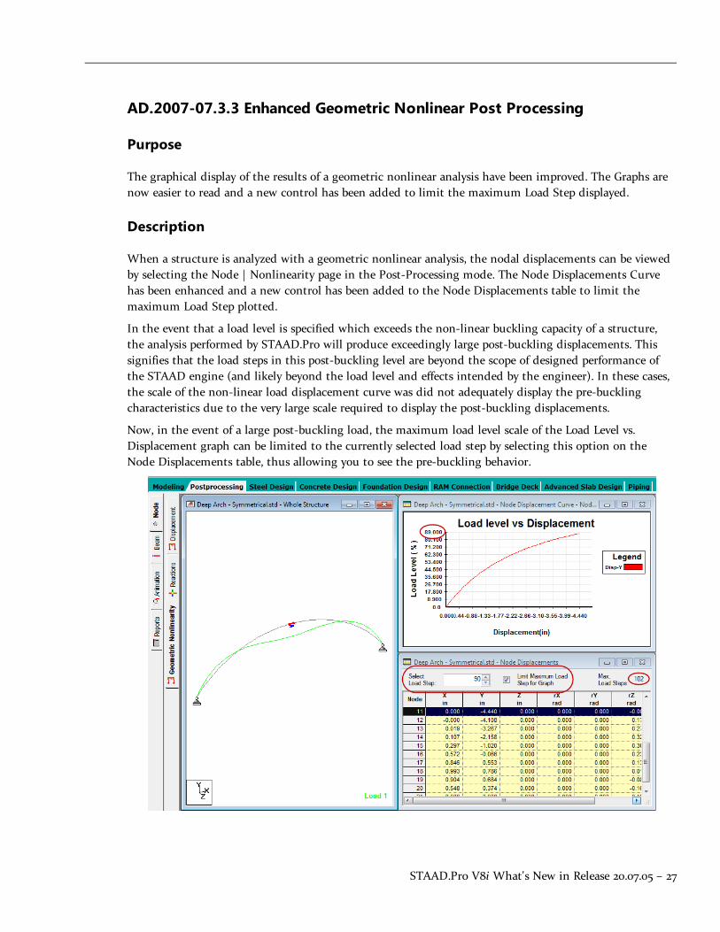
STAAD.Pro V8i What's New in Release 20.07.05 – 27
AD.2007-07.3.3 Enhanced Geometric Nonlinear Post Processing
Purpose
The graphical display of the results of a geometric nonlinear analysis have been improved. The Graphs arenow easier to read and a new control has been added to limit the maximum Load Step displayed.
Description
When a structure is analyzed with a geometric nonlinear analysis, the nodal displacements can be viewedby selecting the Node | Nonlinearity page in the Post-Processing mode. The Node Displacements Curvehas been enhanced and a new control has been added to the Node Displacements table to limit themaximum Load Step plotted.
In the event that a load level is specified which exceeds the non-linear buckling capacity of a structure,the analysis performed by STAAD.Pro will produce exceedingly large post-buckling displacements. Thissignifies that the load steps in this post-buckling level are beyond the scope of designed performance ofthe STAAD engine (and likely beyond the load level and effects intended by the engineer). In these cases,the scale of the non-linear load displacement curve was did not adequately display the pre-bucklingcharacteristics due to the very large scale required to display the post-buckling displacements.
Now, in the event of a large post-buckling load, the maximum load level scale of the Load Level vs.Displacement graph can be limited to the currently selected load step by selecting this option on theNode Displacements table, thus allowing you to see the pre-buckling behavior.

28 – STAAD.Pro V8i What's New in Release 20.07.05
AD.2007-07.3.4 AutoPIPE V8i (SELECTseries 2) and PipeLink support
Overview
STAAD.Pro is now capable of two-way data exchange with AutoPIPE via a new PipeLink utility.Additionally, the tools for transferring loads between the pipe model and the structural model have beenenhanced such that you can now select, update, and remove loads to be applied to the structural model.
Note: For details on the updates to Bentley AutoPIPE V8i, refer to the documentation included withthat product.
Description
Some of the new features and enhancements include:
l The integration between STAAD.Pro and AutoPIPE has been enhanced to allow bi-directional trans-fer of data between STAAD.Pro and AutoPIPE. This is accomplished through a new plug-in pro-gram called PipeLink, which is used to generate common database files for use in bothAutoPIPE and STAAD.Pro.
l The system now allows pipe models to be imported from a number of databases and these modelsmay all be stored locally. Work is then peformed on the active model.
l The loading transfer process has been significantly revised. The mappings between the pipe loadingsand the generated structure loadings are recorded so that these structure loadings may be revisedor removed rather than the previous once-only method. Further, loads can now be modifiedindividually.
l The program now connects pipe supports – rather than pipe nodes – to the structure. This allowsboth node and support labels to be used. This allows additional filters in the connection wizardand also allows STAAD.Pro to import multiple supports at a single support node.
l Pipe supports are now graphically displayed with icons which reflect the nature of the pipe support.The display of these icons, along with other pipe model elements, can be controlled through a newtab in the Diagrams dialog.
l A new section of the online documentation has been added for the Piping mode. This can befound Section 7 of the STAAD.Pro User Interface help.
Refer to the What's New in the Piping Mode section for additional information on using these new andupdated features.
AD.2007-07.3.5 Transverse IRC Loading in STAAD.Beava
Overview
For the specific bridge width, IRC (Indian Road Congress) chapter 6-2000, table 2, clause 207.4 defines therules to combine the live loads. This new feature allows you to either use these IRC live load rules or usean iterative, custom method. If the IRC rule option is selected, this function uses the appropriate live

STAAD.Pro V8i What's New in Release 20.07.05 – 29
loads and number of design lanes and the generates all the possible load combinations as stated for thisparticular bridge width. Otherwise, you can select a specific live load and design lane to generatecombinations.
Description
Loading rules per IRC Chapter 6 are applied in much the same way as previous codes. The definedroadway for the selected deck(s) is divided into design lanes and the selected load class is applied to thestructure achieve the specified actions.
> To specify loading per IRC Chapter 6
1. Open an analyzed bridge model in the Bridge Deck mode.
2. Create Deck and Roadway definitions.
3. Generate influence surfaces for the structure.
4. Select Loading > Run Load Generator….
The Load Generation Parameters dialog General tab opens.
5. Select IRC Chapter 3 for the Design Code and select the appropriate Limit State.
The <code> tab updates to display IRC Loading.
6. Select the IRC Loading tab.
7. Select the appropriate Loading Class.
Note: Combinations of the AA, B, and 70R vehicles have been added to the included vehicledefinitions. These may be reviewed in the Vehicle Database dialog.
8. (Optional) Specify an impact factor or modify the Multiple Presence Factors as needed.

30 – STAAD.Pro V8i What's New in Release 20.07.05
9. Specify the decks for consideration on the Decks tab and the load effects to dictate load placementon the Node Displacements, Support Reactions, Plate Center Stresses, and Beam End Forces tabs.
10. Click the OK button.
The program places the selected loads in design lanes to produce the maximum or minimumeffects requested. A text file containing a summary of the generated loads and corresponding effectsis opened in a text editor for review.
AD.2007-07.3.6 STAAD.foundation V8i Integration
Overview
The export of support geometry and reactions to STAAD.foundation V8i can now be initiated from withinSTAAD.Pro using the Foundation Design mode. This feature is similar to the Import STAAD.Pro Filecapability included in STAAD.foundation.
Description
When selected, the Foundation Mode opens the Foundation page which contains a view of the wholestructure and the Foundation Design Options dialog.
From here, you can select to include all supports, you can graphically select supports, or you can specify alist of support numbers for exporting to a STAAD.foundation project. Similarly, the load cases from theanalysis are listed for inclusion in the STAAD.foundation project.
Hint:Models containing a large number of supported nodes or load cases may result in slowperformance on older computer hardware. Exporting a limited set of data can be used to improveperformance in STAAD.foundation in these cases.
Planned future enhancements also include the export of mat foundations modeled in STAAD.Pro fordesign in STAAD.foundation.
Refer to Section 6 of the Graphical User Interface manual for more information on using the FoundationMode.
AD.2007-07.3.7 Additional Section Databases in RAM Connection mode
Steel section databases for the following countries are now available for use when design connection inRAM Connection mode:
l Indian
l European
l Japanese
l Australian

STAAD.Pro V8i What's New in Release 20.07.05 – 31
Note: Connection design is only performed per the US and British codes available inRAM Connection.
AD.2007-07.4 Additional FeaturesThe following features have yet to undergo testing and are presented "as is."
Note: Items labeled with an asterisk (*) were added in the QA&R release of V8i (SELECTseries 2)(Build 20.07.07.32).
Beta Features
The following features have yet to undergo testing and are presented "as is."
l (None)
AD.2007-07.4.1* Design of Class 4 "Slender" Sections in IS800:2007
The design of slender classified sections (only rolled or welded I sections) per IS:800-2007 has been addedto STAAD.Pro.
The IS:800-2007 code does not provide any clear guidelines about what method should be adopted for thedesign of slender section. The "Flange Only" concept has been adopted where it is assumed that flexure istaken by the flanges alone and the web will resist shear with adequate shear buckling resistance. Thismeans that the flange elements must be non-slender with slender web element to qualify for slendersection that can be designed. If any of the flanges become slender, the design will not be performed forBending and a warning message is displayed.
Refer to Section 9E of the International Design Codes manual for additional information on the designprocedures used for slender sections for IS800:2007 as well as a verification example problem.


Section 3
STAAD.Pro V8i (SELECTseries 1)
IntroductionThe Software Release Report for STAAD.Pro V8i (SELECTseries 3)contains detailed information onadditions and changes that have been implemented since the release of STAAD.Pro V8i (release20.07.05) This document should be read in conjunction with all other STAAD.Pro manuals,including the Revision History document.
AD.2007-06.1 Features Affecting the General Program
This section describes features that have been added that affect the general behavior of theSTAAD.Pro application.
Release Report 20.07.08 — 33

AD.2007-06.1.1 CIS/2 Translator Update
Purpose
The STAAD.Pro tool to import and export models with the CIS/2 translator has been enhancedfor the transfer of models into 3D modeling, such as Intergraph SmartPlant® 3D (SP3D).
Description
The CIS/2 (CimSteel Integration Standard, Version 2) allows for the transfer of steel models usinga prescribed data standard in the STEP (Part 21) format. These files can contain different modelsincluding analysis models. In previous versions of STAAD, CIS/2 files could not be imported intoan existing STAAD file. The import process has now been updated so that new STAAD input filescan be created or existing input files updated from a CIS/2 file.
STAAD will retain all relevant information generated by SP3D - including the object IDs (GUIDs)- when importing CIS/2 files. Further modeling operation will be done in STAAD which includesspecial purpose load generations, analysis, design and member selections and modifications. Youmay then export out to a CIS/2 STEP file and retain all information inherited from SP3D STEPfile and addition/deletion/modification information performed in STAAD.
Using import and export of STEP files in SP3D, further modification can be made in SP3D andthe STAAD model can be updated its model. Only geometry, member properties, boundarycondition information are within the update scope of STAAD. While updating the STAAD modelno other information will be considered. This round-trip process can be repeated an unlimitednumber of times
Additionally, two new VBS Macros have been included in the User Tools to aide in theverification of model integrity before and after update operations using the Import dialog. Thesemay be found in the User Tools drop-down menu in the File toolbar or under Tools > User Tools.
> Importing or Updating with CIS/2 Files
The initial structural model will be created in your external 3D modeling software and exportedas a CIS/2 STEP file, consisting of both analytical and physical model definitions. Limited loadmodeling can be done in some modeling software - such as SmartPlant® 3D - before the initialexport.
1. In STAAD.Pro, select File > Import…
The Import dialog opens.
34 — STAAD.Pro V8i (SELECTseries 3)
Chapter — 3
AD.2007-06.1 Features Affecting the General Program

2. Select either to Create new model from CIS/2 model or Update mode from CIS/2 model.
Note: The option to Create new model from CIS/2 model will only be available in anempty STAAD.Pro project. For STAAD.Pro projects with model content, the option toupdate will be available.
3. Click the Import button.
The Cis2Link dialog opens.
4. Click the Import Model button.
Note: If you are updating an existing STAAD model, the button changes to displayUpdate STAAD Model.
The data is read and the import progress is reported in the log window. Click the Save LogFile button to save this information to a text file.
Section 3 STAAD.Pro V8i (SELECTseries 1)
AD.2007-06.1 Features Affecting the General Program
Release Report 20.07.08 — 35

5. Click the Close button.
The model data has been imported into your STAAD project.
> Export to CIS/2 Files
1. Select File > Export…
The Export dialog opens
2. Select the CIS/2 format.
3. Click the Export button.
The Cis2Link dialog opens.
4. Click the Export Model button.
The data export progress is displayed in the log window. Click the Save Log File button tosave this information to a text file.
5. Click the Close button.
36— STAAD.Pro V8i (SELECTseries 3)
Chapter — 3
AD.2007-06.1 Features Affecting the General Program
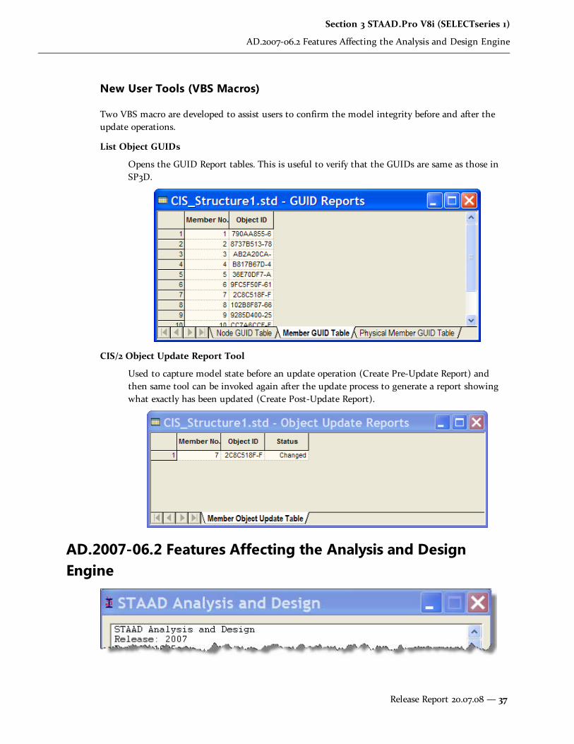
New User Tools (VBS Macros)
Two VBS macro are developed to assist users to confirm the model integrity before and after theupdate operations.
List Object GUIDs
Opens the GUID Report tables. This is useful to verify that the GUIDs are same as those inSP3D.
CIS/2 Object Update Report Tool
Used to capture model state before an update operation (Create Pre-Update Report) andthen same tool can be invoked again after the update process to generate a report showingwhat exactly has been updated (Create Post-Update Report).
AD.2007-06.2 Features Affecting the Analysis and DesignEngine
Section 3 STAAD.Pro V8i (SELECTseries 1)
AD.2007-06.2 Features Affecting the Analysis and Design Engine
Release Report 20.07.08 — 37

The following section describes the new features that have been added to the analysis and designengine and existing features that have been updated or modified.
AD.2007-06.2.1 ANSI/AISC N690-1994 Design Code
Purpose
For steel design, STAAD compares the actual stresses with the allowable stresses as defined by the"ANSI/AISC N690-1984: Nuclear Facilities - Steel Safety-Related Structures for Design,Fabrication, and Erection."
Description
The parameter CODE AISC N690 1984 is used to initiate code checking per ANSI/AISC N690-1984.
The full details for this code - including parameters, commands, and technical background - arein the International Design Code manual section 17B "ANSI/AISC N690-1984 Code".
> Use the ANSI/AISC N690 1984 code
1. In the modeling mode, select the Design page and Steel material sub-page.
2. Select AISC N690 1984 in the Current Code drop-down list.
AD.2007-06.2.2 Update to Russian Concrete Design
The Russian SNiP concrete design routines have been updated to accommodate newreinforcement and concrete class definitions. In order that these new classes can be assigned tomembers that are to be designed, the following changes have taken place in the RCL, BCL andRHS parameters.
Refer to the International Codes Manual, section 12A "Russian Codes – Concrete Design perRussian Code (SNiP 2.03.01-84*)" for additional information.
Additionally a few other minor updates have been incorporated to ensure axial tension is ignoredin column design and that the provided area of steel in both directions is not less than theminimum.
Note: STAAD.Pro supports design of concrete beams and columns to Russian SP52 code issupported in the interactive RC Designer module (Concrete Design Mode in the GUI). Formore details of the RC Designer see the RC Designer manual found in the AdditionalModules section of the online help. For details on the SP52 details see "AD.2007-1001.4.1 Beamand Column Designs to the Russian Concrete Code SP52."
38— STAAD.Pro V8i (SELECTseries 3)
Chapter — 3
AD.2007-06.2 Features Affecting the Analysis and Design Engine

> Select reinforcement or concrete class definitions
1. In the modeling mode, select the Design page and Concrete material sub-page.
2. Select SNiP 2.03 01-84 in the Current Code drop-down list.
3. Click the Define Parameters button below the model outline panel.
4. The RCL, BCL, and RSH parameters have the new definitions available. Refer to theInternational Codes Manual for additional information.
Reinforcement Class for longitudinal reinforcement (RCL):
Section 3 STAAD.Pro V8i (SELECTseries 1)
AD.2007-06.2 Features Affecting the Analysis and Design Engine
Release Report 20.07.08 — 39
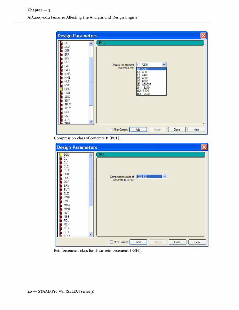
Compression class of concrete B (BCL):
Reinforcement class for shear reinforcement (RSH):
40 — STAAD.Pro V8i (SELECTseries 3)
Chapter — 3
AD.2007-06.2 Features Affecting the Analysis and Design Engine

AD.2007-06.2.3 Eurocode 3 National Annex
Two country's National Annex to Eurocode 3 have been incorporated into the Steel design modulein STAAD.Pro: United Kingdom and France. As with the other National Annexes to EC-3, thisimplementation will make use of the NA parameter.
Section 3 STAAD.Pro V8i (SELECTseries 1)
AD.2007-06.2 Features Affecting the Analysis and Design Engine
Release Report 20.07.08 — 41

Warning: The GB1 parameter (which, in fact was common to the base EC-3 and was areminiscent of the previous DD ENV implementation of EC-3) has been removed. Hence anylegacy STAAD files that have the GB1 Parameter defined will need to be revised to take outthis parameter as it is no longer valid as per the latest EN1993.
AD.2007-06.2.3.1 United Kingdom National Annex to Eurocode 3 (EN1993-1-1:2005)
The UK National Annex document referred to is “NA to BS EN 1993-1-1:2005”.
> To Initiate a EC3-UK NA Steel Design
1. In the Modeling mode, click the Design > Steel tab.
2. In the Current Code drop-down menu, select EN 1993-1-1:2005.
3. Click the Define Parameters button. The Design Parameters dialog opens.
4. Select the NA parameter in the list box.
5. Select the option for (1) United Kingdom.
6. Click Add.
This will insert the following command into the STAAD input file:
CODE EN 1993-1-1:2005
NA 1
For additional information, please refer to the International Design Codes manual, sections 5B.(B)"Steel Design to Eurocode 3" and 5B.(C) "EC3 National Annexes."
AD.2007-06.2.3.2 French National Annex to Eurocode 3 (EN 1993-1-1:2005)
The French National Annex document referred to is “Annexe Nationale a la NF EN 1993-1-1:2005”.
> To Initiate a EC3-French NA Steel Design
1. In the Modeling mode, click the Design > Steel tab.
2. In the Current Code drop-down menu, select EN 1993-1-1:2005.
3. Click the Define Parameters button. The Design Parameters dialog opens.
4. Select the NA parameter in the list box.
5. Select the option for (4) France.
6. Click Add.
This will insert the following command into the STAAD input file:
42— STAAD.Pro V8i (SELECTseries 3)
Chapter — 3
AD.2007-06.2 Features Affecting the Analysis and Design Engine

CODE EN 1993-1-1:2005
NA 4
For additional information, please refer to the International Design Codes manual, sections 5B.(B)"Steel Design to Eurocode 3" and 5B.(C) "EC3 National Annexes."
AD.2007-06.2.4 Chinese Static Seismic Loading
Purpose
A simplified base shear method of the seismic load generation for the Chinese code has beenadded to STAAD.Pro V8i.
This set of commands may be used to define and generate static equivalent seismic loads as perChinese specifications GB50011-2001. This load uses a static equivalent approach, similar to thatfound in the UBC. Depending on this definition, equivalent lateral loads will be generated in thehorizontal direction(s).
Description
The seismic load generator can be used to generate lateral loads in the X and Z directions for Y upand the X and Y directions for Z up; where Y up or Z up is the vertical axis parallel to the directionof gravity loads (see the SET Z UP command).
Note: All vertical coordinates of the floors above the base must be positive and the vertical axismust be perpendicular to the floors.
This method of seismic load generation is limited in use to buildings not taller than 40 meters,with deformations predominantly due to shear, and a rather uniform distribution of mass andstiffness in elevation. Alternately, for buildings modeled as a single-mass system, a simplifiedmethod such as this base shear method, may be used.
> Adding GB50011-2001 Seismic Loading
1. Click on the General | Load & Definitions page in the Modeling mode.
2. Select Definitions > Seismic Definitions.
3. Click the Add button.
The Add New: Seismic Definitions dialog opens.
Section 3 STAAD.Pro V8i (SELECTseries 1)
AD.2007-06.2 Features Affecting the Analysis and Design Engine
Release Report 20.07.08 — 43
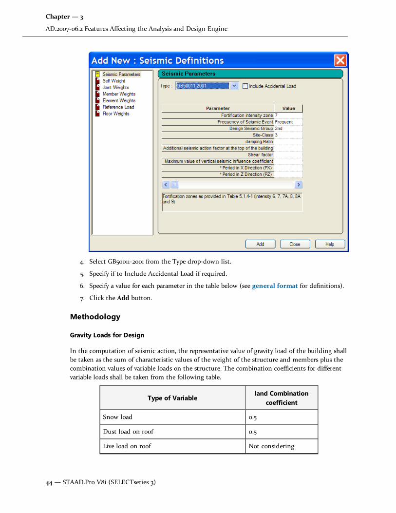
4. Select GB50011-2001 from the Type drop-down list.
5. Specify if to Include Accidental Load if required.
6. Specify a value for each parameter in the table below (see general format for definitions).
7. Click the Add button.
Methodology
Gravity Loads for Design
In the computation of seismic action, the representative value of gravity load of the building shallbe taken as the sum of characteristic values of the weight of the structure and members plus thecombination values of variable loads on the structure. The combination coefficients for differentvariable loads shall be taken from the following table.
Type of Variableland Combination
coefficient
Snow load 0.5
Dust load on roof 0.5
Live load on roof Not considering
44 — STAAD.Pro V8i (SELECTseries 3)
Chapter — 3
AD.2007-06.2 Features Affecting the Analysis and Design Engine
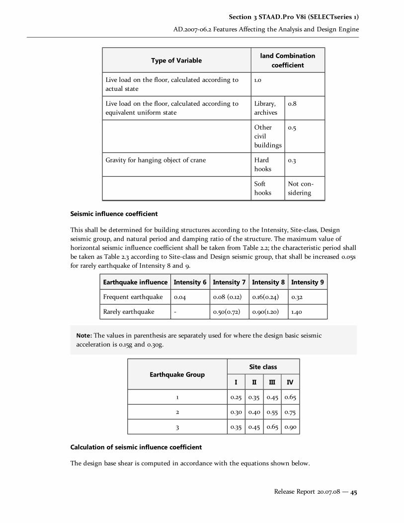
Type of Variableland Combination
coefficient
Live load on the floor, calculated according toactual state
1.0
Live load on the floor, calculated according toequivalent uniform state
Library,archives
0.8
Othercivilbuildings
0.5
Gravity for hanging object of crane Hardhooks
0.3
Softhooks
Not con-sidering
Seismic influence coefficient
This shall be determined for building structures according to the Intensity, Site-class, Designseismic group, and natural period and damping ratio of the structure. The maximum value ofhorizontal seismic influence coefficient shall be taken from Table 2.2; the characteristic period shallbe taken as Table 2.3 according to Site-class and Design seismic group, that shall be increased 0.05sfor rarely earthquake of Intensity 8 and 9.
Earthquake influence Intensity 6 Intensity 7 Intensity 8 Intensity 9
Frequent earthquake 0.04 0.08 (0.12) 0.16(0.24) 0.32
Rarely earthquake - 0.50(0.72) 0.90(1.20) 1.40
Note: The values in parenthesis are separately used for where the design basic seismicacceleration is 0.15g and 0.30g.
Earthquake GroupSite class
I II III IV
1 0.25 0.35 0.45 0.65
2 0.30 0.40 0.55 0.75
3 0.35 0.45 0.65 0.90
Calculation of seismic influence coefficient
The design base shear is computed in accordance with the equations shown below.
Section 3 STAAD.Pro V8i (SELECTseries 1)
AD.2007-06.2 Features Affecting the Analysis and Design Engine
Release Report 20.07.08 — 45

The damping adjusting and forming parameters on the building seismic influence coefficientcurve (Fig.2.1) shall comply with the following requirements:
A. The damping ratio of building structures shall select 0.05 except otherwise provided, thedamping adjusting coefficient of the seismic influence coefficient curve shall select 1.0, andthe coefficient of shape shall conform to the following provisions:
a. Linear increase section, whose period (T) is less than 0.1 s;
b. Horizontal section, whose period form 0. is thought to characteristic period, shallselect the maximum value (αmax);
c. Curvilinear decrease section, whose period from characteristic period thought to 5times of the characteristic period, the power index (γ) shall choose 0.9.
d. Linear decrease section, whose period from 5 times characteristic period thought to6s, the adjusting factor of slope (η1) shall choose 0.02.
Figure 2.1 Seismic influence coefficient curve
B. When the damping adjusting and forming parameters on the seismic influence coefficientcurve shall comply with the following requirements:
a. The power index of the curvilinear decrease section shall be determined accordingto the following equation E2.1
E2.1
Where:
γ- the power index of the curvilinear decrease section;
ξ- the damping ratio.
b. The adjusting factor of slope for the linear decrease section shall be determinedfrom following equation:
η1=0.02+(0.05-ζ)/8 E2.2
Where:
46— STAAD.Pro V8i (SELECTseries 3)
Chapter — 3
AD.2007-06.2 Features Affecting the Analysis and Design Engine

η1- the adjusting factor of slope for the linear decrease section, when itis less than 0, shall equal 0.
c. The damping adjustment factor shall be determined according to the followingequation:
E2.3
Where:
η2- the damping adjustment factor, when it is smaller than 0.55 shallequal 0.55.
Calculation of horizontal seismic action
When the base shear force method is used, only one degree of freedom may be considered for eachstory; the characteristic value of horizontal seismic action of the structure shall be determined bythe following equations (Fig. 2.2):
E2.4
E2.5
E2.6
Figure 2.2 Calculation of horizontal seismic action
Section 3 STAAD.Pro V8i (SELECTseries 1)
AD.2007-06.2 Features Affecting the Analysis and Design Engine
Release Report 20.07.08 — 47

Where:
FEk- characteristic value of the total horizontal seismic action of the structure.
α1- horizontal seismic influence coefficient corresponding to the fundamentalperiod of the structure, which shall be determined by using Clause 2.3. Formultistory masonry buildings and multi-story brick buildings with bottom-framesor inner-frames, the maximum value of horizontal seismic influence coefficientshould be taken.
Geq- equivalent total gravity load of a structure. When the structure is modeled as asingle-mass system, the representative value of the total gravity load shall be used;and when the structure is modeled as a multi-mass system, the 85% of therepresentative value of the total gravity load may be used.
Fi— characteristic value of horizontal seismic action applied on mass i-th .
Gi, Gj— representative values of gravity load concentrated at the masses of i-th andj-th respectively, which shall be determined by Clause 2.1.
Hi,Hj - calculated height of i-th and j-th from the base of the building respectively.
δn— additional seismic action factors at the top of the building; for multi-storyreinforced concrete buildings, it may be taken using Table 2.4; for multi-story brickbuildings with inner-frames, a value of 0.2 may be used; no need to consider forother buildings
ΔFn - additional horizontal seismic action applied at top of the building.
Table 2.4 Additional seismic action factors at top of the building
Tg (s) T1 > 1.4Tg T1≤1.4Tg
≤0.35 0.08T1+0.07 0.0
<0.35 ≈ 0.55 0.08T1+0.01
>0.55 0.08T1-0.02
Table 2.4 - Additional seismic action factors at top of thebuilding
Note: T, is the fundamental period of the structure.
The horizontal seismic shear force at each floor level of the structure shall comply with therequirement of the following equation:
E2.7
Where:
48— STAAD.Pro V8i (SELECTseries 3)
Chapter — 3
AD.2007-06.2 Features Affecting the Analysis and Design Engine

VEki- the floor i-th shear corresponding to horizontal seismic action characteristicvalue.
λ- Shear factor, it shall not be less than values in Table 2.5; for the weak location ofvertical irregular structure, these values shall be multiplied by the amplifying factorof 1.15.
Gj- the representative value of gravity load in floor j-th of the structure.
StructuresIntensity
7Intensity
8Intensity
9
structures with obvious torsion effect orfundamental period is less than 3.5s
0.16(0.024)
0.032(0.048)
0.064
Structures with fundamental period greaterthan 5.0s
0.012(0.018)
0.024(0.032)
0.040
Table 2.5 Minimum seismic shear factor value of the floor level
Note:1. The values may be selected through interpolation method for structures whosefundamental period is between 3. 5s and 5s.
2. Values in the brackets are used at the regions with basic seismic acceleration as 0.15gand 0.30g respectively.
Calculation of vertical seismic action:
For tall buildings for Intensity 9, the characteristic value of vertical seismic action shall bedetermined by the following equations (figure 2.3). The effects of vertical seismic action at floorlevel may be distributed in proportion of representative value of gravity load acting on themembers, which should multiply with the amplified factor 1.5:
E2.8
E2.9
Where:
FEvk - characteristic value of the total vertical seismic actions of the structure.
Fv - characteristic value of vertical seismic action at the level of mass i-th.
αvmax- maximum value of vertical seismic influence coefficient, which may be takenas 65% of the maximum value of the horizontal seismic influence coefficient.
Section 3 STAAD.Pro V8i (SELECTseries 1)
AD.2007-06.2 Features Affecting the Analysis and Design Engine
Release Report 20.07.08 — 49

Geq- equivalent total gravity load of the structure, which may be taken as 75% ofthe representative value of the total gravity load of the structure.
Figure 2.3 Sketch for the computation of vertical seismic action
Complementarities:
1. Structures having the oblique direction lateral-force-resisting members and the obliqueangel to major orthogonal axes is greater than 150, the horizontal seismic action along thedirection of each lateral-force-resisting member shall he considered respectively. So wecould consider this though the item, the action of the oblique member could be mul-tiplied by this factor as design force.
2. Eccentricity: similar to UBC code. The eccentricity value of gravity center on each floorshould be ei = ±0.05Li,where:
ei - Eccentricity value of gravity center on i-th floor.
Li, - maximum width of calculated story of the building.
3. Structures having obviously asymmetric mass and stiffness distribution, the torsion effectscaused by both two orthogonal horizontal direction seismic action shall be considered; andother structures, it is permitted that a simplified method, such as adjusting the seismiceffects method, to consider their seismic torsion effects.
So we may use the to decide which whether torsion effects should be considered.
General Format
The following general format should be used to generate loads in a particular direction.
DEFINE GB (ACCIDENTAL) LOAD
INTENSITY { 6 | 7 | 7A | 8 | 8A | 9 } { FREQUENT | RARE } GROUP { 1 | 2 | 3} SCLASS { 1 | 2 | 3 | 4 } (DAMP f1) (DELN f2) (SF f3) (AV f4) (PX f5) (PZ f6)
Where:
50 — STAAD.Pro V8i (SELECTseries 3)
Chapter — 3
AD.2007-06.2 Features Affecting the Analysis and Design Engine

l INTENSITY is the Fortification Intensity (ref. table 5.1.4-1)
l Frequency of seismic action, as specified by either FREQUENT or RARE (ref. table 5.1.2-2)
l GROUP is Design Seismic Group (ref. table 5.1.4-2)
l SCLASS is Site-Class (ref. table 5.1.4-2)
l f1 = damping ratio (default = 0.05 for 5% damping)
l f2 = δn , Additional seismic action factor at the top of the building (default as calculatedfrom Table 5.2.1)
l f3 = Shear Factor λ, Minimum seismic shear factor of the floor (default as calculated fromTable 5.2.5)
l f4 = maximum value of vertical seismic influence coefficient α(v,max) (default=0.0) (ref. sec-tion 5.3)
As a fraction of total vertical load is to be considered such as 0.75Geq, specify the product of thefactor on maximum horizontal seismic influence factor and factor of total gravity load as f4. Forinstance,
l α(v,max) = 0.65αmaxAnd
l Gv,eq = 0.75Geq
l Specify f4 as (0.65*0.75) i.e. equal to 0.4875
l f5 and f6 = optional time period along two horizontal direction (X and Y, respectively).
To apply the load in any load case, following command would be used
LOAD CASE 1
GB LOAD X factor
Example
Example output:
******************************************************************-***********
* *
* EQUIV. SEISMIC LOADS AS PER SEISMIC DESIGN CODE FOR BUILDINGS*
* (GB50011-2001) OF CHINA ALONG X*
* T CALCULATED = 0.252 SEC. T USER PROVIDED = 1.200 SEC.*
Section 3 STAAD.Pro V8i (SELECTseries 1)
AD.2007-06.2 Features Affecting the Analysis and Design Engine
Release Report 20.07.08 — 51

* T USED = 1.200 SEC.*
* MAX. HORIZONTAL SEISMIC INFLUENCE COEFFICIENT = 0.240*
* CHARACTERISTIC PERIOD = 0.750 SEC.*
* DAMPING RATIO = 0.030 POWER INDEX (GAMMA) = 0.931*
* DAMPING ADJUSTMENT FACTOR (ETA2) = 1.180*
* ADJUSTING FACTOR (ETA1) = 0.022*
* HORIZONTAL SEISMIC INFLUENCE COEFFICIENT (ALPHA1) = 0.183(18.288%) *
* MINIMUM SHEAR FACTOR AS PER SEC. 5.2.5 (LAMBDA) = 0.050 (5.000%) *
* TOTAL HORIZONTAL SEISMIC ACTION =*
* = 0.183 X 285.529 = 52.218 KIP*
* DESIGN BASE SHEAR = 0.750 X 52.218*
* = 39.164 KIP*
* ADDITIONAL SEISMIC ACTION FACTOR (DELTAN) = 0.020*
* VERTICAL SEISMIC INFLUENCE COEFFICIENT (ALPHA,VMAX) = -0.108*
* TOTAL VERTICAL SEISMIC ACTION =*
* = -0.108 X 285.529 = -30.837 KIP*
* TOTAL DESIGN VERTICAL LOAD = 0.750 X -30.837*
* = -23.128 KIP*
52— STAAD.Pro V8i (SELECTseries 3)
Chapter — 3
AD.2007-06.2 Features Affecting the Analysis and Design Engine

**
******************************************************************-***********
CHECK FOR MINIMUM LATERAL FORCE AT EACH FLOOR [GB50011-2001:5.2.5]
LOAD - 1 FACTOR - 0.750
FLOOR LATERAL GRAVITY LAMBDA LAMBDAADJUSTMENT
HEIGHT (KIP ) LOAD (KIP ) LOAD (KIP ) (%) MIN(%) FACTOR
------------- ----------- ------------ ------ -----------------
30.000 23.406 79.045 29.61 5.001.00
20.000 19.208 180.888 10.62 5.001.00
10.000 9.604 282.731 3.40 5.001.47
JOINT LATERAL TORSIONAL VERTICALLOAD - 1
LOAD (KIP ) MOMENT (KIP -FEET) LOAD (KIP ) FACTOR -0.750
----- ------- --------- -----------
17 FX 0.541 MY 0.000 FY -0.221
18 FX 0.663 MY 0.000 FY -0.271
19 FX 0.663 MY 0.000 FY -0.271
20 FX 0.541 MY 0.000 FY -0.221
21 FX 0.663 MY 0.000 FY -0.271
Section 3 STAAD.Pro V8i (SELECTseries 1)
AD.2007-06.2 Features Affecting the Analysis and Design Engine
Release Report 20.07.08 — 53

22 FX 0.785 MY 0.000 FY -0.321
23 FX 0.785 MY 0.000 FY -0.321
24 FX 0.663 MY 0.000 FY -0.271
25 FX 0.663 MY 0.000 FY -0.271
26 FX 0.785 MY 0.000 FY -0.321
27 FX 0.785 MY 0.000 FY -0.321
28 FX 0.663 MY 0.000 FY -0.271
29 FX 0.541 MY 0.000 FY -0.221
30 FX 0.663 MY 0.000 FY -0.271
31 FX 0.663 MY 0.000 FY -0.271
32 FX 0.541 MY 0.000 FY -0.221
----------- ----------- ----------------
TOTAL = 10.602 0.000 -0.221AT LEVEL 10.000 FEET
AD.2007-06.3 Features Affecting the RAM Connection DesignMode
Several new features have been added and existing features have been modified in the RAMConnection Design Mode. These are explained in the following pages.
Note: Full use of the RAM Connection Mode requires access to a valid RAM Connectionlicense. If you do not possess a license, contact your Bentley account manager to have itadded to your SELECT licenses. Without a valid license, only a small subset of the full rangeof available RAM connections can be utilized.
54 — STAAD.Pro V8i (SELECTseries 3)
Chapter — 3
AD.2007-06.3 Features Affecting the RAM Connection Design Mode

AD.2007-06.3.1 RAM Connection V8i support
Purpose
The enhancements included in Bentley's RAM Connection V8i (release 5.5) are now available inSTAAD.Pro. Additionally, the connection assignment and design process has been streamlinedwithin STAAD.Pro. Now, joints and connections can be automatically assigned for a set of selectedmembers and connection designs can be grouped together. Additionally, when a connection isedited using the RAM Connection pad, those changes will be saved in the STAAD.Pro modeldesign.
Description
Connections are designed in the newly updated RAM Connection Mode by creating ‘Joints’, fromthe geometry, section properties and forces resulting from the analysis and assigning a design briefmade up of connection templates. A suitable connection design, if one is available, will be reportedonce you have selected the appropriate connection templates.
In previous releases of STAAD.Pro, you were able to only select and assign a connection toindividual joints. Now, any number of joints may be selected and designed. Further, connectiondesign is performed automatically for you once appropriate templates have been selected for theselected joints. These enhancements greatly reduce the time required for connection design inmodels of all sizes.
Hint: The selected load envelope is now used for all connection designs, instead of per designbrief as in previous versions of STAAD.Pro.
For additional information on using this mode, refer to the RAM Connection mode manual,found in the Additional Modules section of the STAAD.Pro Online Help.
AD.2007-06.4 Features Affecting the Piping Mode
STAAD.Pro can utilize the pipe layout and reactions created in the applications ADLPipe orAutoPipe. The pipe model can be imported in the Piping Mode. The following describes themethod of using the Piping Mode and features recently added to this mode.
AD.2007-06.4.1 AutoPIPE Integration Enhancements
Overview
An enhancement to how pipe/structure connections are assigned has been made to the Pipingmodule. A new Support Connection Wizard is available to allow you to add multiple supports tothe entire model or a subset of a model, based on some general parameters.
Section 3 STAAD.Pro V8i (SELECTseries 1)
AD.2007-06.4 Features Affecting the Piping Mode
Release Report 20.07.08 — 55
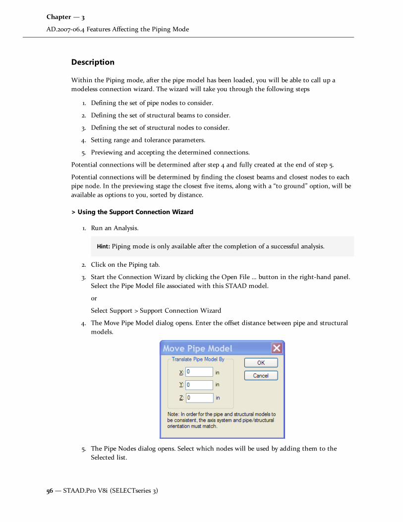
Description
Within the Piping mode, after the pipe model has been loaded, you will be able to call up amodeless connection wizard. The wizard will take you through the following steps
1. Defining the set of pipe nodes to consider.
2. Defining the set of structural beams to consider.
3. Defining the set of structural nodes to consider.
4. Setting range and tolerance parameters.
5. Previewing and accepting the determined connections.
Potential connections will be determined after step 4 and fully created at the end of step 5.
Potential connections will be determined by finding the closest beams and closest nodes to eachpipe node. In the previewing stage the closest five items, along with a “to ground” option, will beavailable as options to you, sorted by distance.
> Using the Support Connection Wizard
1. Run an Analysis.
Hint: Piping mode is only available after the completion of a successful analysis.
2. Click on the Piping tab.
3. Start the Connection Wizard by clicking the Open File … button in the right-hand panel.Select the Pipe Model file associated with this STAAD model.
or
Select Support > Support Connection Wizard
4. The Move Pipe Model dialog opens. Enter the offset distance between pipe and structuralmodels.
5. The Pipe Nodes dialog opens. Select which nodes will be used by adding them to theSelected list.
56— STAAD.Pro V8i (SELECTseries 3)
Chapter — 3
AD.2007-06.4 Features Affecting the Piping Mode

The filtering options are All, Connected and Unconnected (relating to whether aconnection to the STAAD.Pro model has been defined). When support type information isavailable the filter will be expanded to include these as well.
6. The Structure Beams dialog opens. Select which structure elements will be used by addingthem to the Selected list.
The filtering options are implemented with two combo boxes, one for the category and oneto identify the subset within that category. Available filtering options are All, Group, Viewand Property.
7. The Structure Node dialog opens. Select which structure nodes will be used by adding
Section 3 STAAD.Pro V8i (SELECTseries 1)
AD.2007-06.4 Features Affecting the Piping Mode
Release Report 20.07.08 — 57

them to the Selected list.
The filtering options are implemented with two combo boxes, one for the category and oneto identify the subset within that category. Available filtering options are All, Group andView.
8. The Parameters dialog opens. Here you will set some parameters so the wizard canestablish pipe connections.
See "Parameter Page / Connection Finder" on page 59 for additional details on thesesettings.
58— STAAD.Pro V8i (SELECTseries 3)
Chapter — 3
AD.2007-06.4 Features Affecting the Piping Mode

9. The results of the Wizard will be displayed in the final dialog. Review these results and ifchanges are necessary, you may click the < Back button. Otherwise, click the Finish buttonto accept.
The results will be presented in a table with columns for pipe node id and for the structuralitem it is to be connected to. This second column will provide a drop list allowing the userto choose either ‘No connection’ or one of up to 5 closest items. The items will be listedwith the closest at the top. The initial state will be the closest item or ‘Ground’, if no goodmatches were found.
Parameter Page / Connection Finder
The connection finding routine runs in two parts. First looking at beams (length of perpendicularfrom beam) and then looking at nodes (straight line length). The five closest found connectablepoints are saved to be presented on the results page. In order to provide control over theconnection finder, several parameters are available to you for editing. The default values ofdistance-based parameters will depend on the base unit of STAAD.Pro.
General
l Max. Range: double: default 2m / 6’ : Potential connections beyond Max. Range will be dis-carded.
l Insert nodes into beams at connection points: default true : This parameter effects the con-nection of the structures rather the point finding algorithm. If set true a new node will becreated at each intermediate beam point and the connection made to that rather than tothe beam itself. If the algorithm finds new node points within “End Tolerance” of eachother then only one new node will be added.
Section 3 STAAD.Pro V8i (SELECTseries 1)
AD.2007-06.4 Features Affecting the Piping Mode
Release Report 20.07.08 — 59
Beam
l End Tolerance : double : default 5cm /2” : To allow for differences in precision and to avoidvery short beam breaks this parameter will determine at what distance from the node theperpendicular will be considered to be at the node itself.
l Allow Non-Perpendicular Connection at End Nodes: Boolean : default true: This is onlyreally relevant if the node subset does not explicitly include the nodes at the end ofmembers in the beam subset. If set ‘true’ the beam end nodes will be included in the nodesearch. If set ‘false’ the end nodes of a given beam will only be considered for connectionsperpendicular to the beam, unless they have been explicitly added to the node subset.
This page has no effect on structure diagrams. The connection finding routine is run whenadvancing from this page.
Note: Pipe-structure links are not part of the undo system. Nodes created at the end of thewizard will be removed by an undo but the links are not changed.
Export STAAD.Pro Structure to AutoPipe
A piping engineer who needs to consider the steelwork as their structural supports may need toimport the STAAD model into AutoPipe. A macro is now available in STAAD.Pro to facilitatethis. It will create an .NTL file which is used by AutoPipe. The file will contain just the supportframe data.
The Macro, called TOAUTOPIPEPUB.VBS, is located in the folder C:\SProV8i\STAAD\Plugins(where C:\SProV8i\ is the drive and folder where your copy of STAAD.Pro was installed).
60 — STAAD.Pro V8i (SELECTseries 3)
Chapter — 3
AD.2007-06.4 Features Affecting the Piping Mode

Section 4
STAAD.Pro V8i
IntroductionThe latest What's New document for STAAD.Pro V8i contains detailed information on additionsand changes that have been implemented since the release of STAAD.Pro V8i (2007 build 04). This document should be read in conjunction with all other STAAD.Pro manuals, including theRevision History document.
AD.2007-05.1 Features Affecting the Analysis and DesignEngine
The following section describes the new features have been added to the analysis and designengine and existing features that have been updated or modified.
Release Report 20.07.08 — 61

AD.2007-05.1.1 Geometric Nonlinear Analysis
Purpose
The range of analysis options has been supplemented with a new solution to account fornonlinear effects of moderate displacement and small strain. This solution holds for where theelement distortion is small and small rotations are assumed.
Description
Note: The nonlinear analysis command is secured with the Advanced Analysis Enginepackage.
To invoke a nonlinear analysis:
1. Select the Modeling | Analysis/Print page.
2. If the Analysis/Print Commands dialog does not appear, click the Define Commands…button.
3. Click on the Nonlinear Analysis tab.
4. Set the Nonlinear Analysis Parameters and Print Options (see table below).
5. Click the Add button to add the nonlinear analysis command to the model.
6. Click the Close button to dismiss the Analysis/ Print Commands dialog.
62— STAAD.Pro V8i (SELECTseries 3)
Chapter — 4
AD.2007-05.1 Features Affecting the Analysis and Design Engine

The first analysis step must be stable, otherwise use ARC control to prevent instability. Theprocedure does not use follower loads. Loads are evaluated at the joints before the first step; thenthose loads translate with the joint but do not rotate with the joint. Equilibrium is computed inthe displaced position.
Note: The old NONLINEAR nn ANALYSIS command will adopt the new procedure unless aSET command is used. If a SET command is entered this will invoke the old procedure forbackward compatibility.
General Format
The format of the nonlinear analysis command is such that two data sets are required:
1) Initiate Command
The command is initiated with the line:
PERFORM NONLINEAR ANALYSIS
Section 4 STAAD.Pro V8i
AD.2007-05.1 Features Affecting the Analysis and Design Engine
Release Report 20.07.08 — 63

2) Specify Options
The following table describes the parameters available for nonlinear analysis:
Parameter Name Default Value Description
ARC 0.0 Displacement control. Value isthe absolute displacement limitfor the first analysis step. If max.displacement is greater than thislimit, ARC will calculate a newstep size for the first step and anew value for STEPS. Valueshould be in current lengthunits.
ARC = 0 indicates nodisplacement control.
ITERATION 100 Max. Number of iterations toachieve equilibrium in thedeformed position to the tol-erance specified.
TOLERANCE 0.0001 inch For convergence, two successiveiteration results must have alldisplacements the same withinthis tolerance. Value entered isin current units.
STEPS 1 Number of load steps. Load isapplied in stages if entered. Onemeans that all of the load isapplied in the first step.
REBUILD 1 Frequency of rebuilds of thetangent K matrix per load step &iteration.
0= once per load step
1= every load step & iteration
Geometric Nonlinear Analysis parameters
64 — STAAD.Pro V8i (SELECTseries 3)
Chapter — 4
AD.2007-05.1 Features Affecting the Analysis and Design Engine

Parameter Name Default Value Description
KG 0 This parameter controls whetherthe geometric stiffness, KG, isadded to the stiffness matrix, K.“KG” or “KG 1” -> Use K+KG forthe stiffness matrix. (Default)
“KG 0” -> Do not use KG.
PRINT none Standard STAAD analysis printoptions. See Perform Analysisdocumentation.
Nonlinear entities such as tension/compression members, multilinear springs, gaps, etc. are notsupported when using a nonlinear analysis. Additionally, nonlinear analysis does not account forpost-buckling stiffness of members.
AD.2007-05.1.2 IS 800:2007
Purpose
The Indian Bureau of Standards has released a new version of the design code for the design ofsteel structures, known as IS 800:2007. This replaces the previous version of the code (alsosupported in STAAD.Pro), IS 800:1984, which was versified again in 1998. This is a new approach tosteel design and is based on the limit state design rather than a stress based design of the oldcode.
The Steel Design section has been enhanced to include design per IS 800:2007. Both sectionchecking and selection routines are supported.
Description
The design will follow the same process as used by all other steel design codes currently availablein the STAAD engine. The design of each member is controlled through a set of parameters thathave been added to the GUI Steel Design Dialog under the title IS 800:2007.
The design engine will allow all standard section database sections and User Table sections to bedesigned.
The design process followed:
1. Check slenderness
2. Check classification
3. Check tension forces
4. Check compression forces
5. Check bending Forces
6. Check interaction
The results will be:
Section 4 STAAD.Pro V8i
AD.2007-05.1 Features Affecting the Analysis and Design Engine
Release Report 20.07.08 — 65

1. output to the ANL file
2. available in the member query
3. available in the post processing mode in the Design Results table
For the list of parameters and commands including the default values, please refer to the tablebelow.
Note: The IS 800:2007 design is secured using the STAAD Indian Design Code Pack.
To invoke the new IS 800:2007 code for steel member design
1. From the Steel Design tab, select IS800 2007 from the current code list.
2. Click the Define Parameters… button to launch the Design Parameters dialog.
3. Set and add code parameter as required (see table below).
4. Click the Close button to dismiss the dialog.
General Format
The format of the IS 800:2007 is as follows:
PARAMETERS
CODE IS800 LSD
KY 1.5 MEMB 3 7 TO 11
PROFILE ISWB400 MEMB 1 2 23
TRACK 1 ALL
66— STAAD.Pro V8i (SELECTseries 3)
Chapter — 4
AD.2007-05.1 Features Affecting the Analysis and Design Engine

Design Parameters
ParameterName
DefaultValue
Description
ALPHA 0.8 A Factor, based on the end-connection type, controlling the Rupture Strength of the NetSection
0.6 = For one or two bolts
0.7 = For three bolts
0.8 = For four or more bolts
(as per Section 6.3.3)
ATG None(Mandatoryfor BlockShearcheck)
Minimum Gross Area in Tension from the bolthole to the toe of the angle, end bolt line,perpendicular to the line of the force.
This parameter is applicable only when DBS = 1.0(as per Section 6.4.1).
ATN None(Mandatoryfor BlockShearcheck)
Minimum Net Area in Tension from the bolthole to the toe of the angle, end bolt line,perpendicular to the line of the force.
This parameter is applicable only when DBS = 1.0(as per Section 6.4.1).
AVG None(Mandatoryfor BlockShearcheck)
Minimum Gross Area in shear along bolt lineparallel to external force.
This parameter is applicable only when DBS = 1.0(as per Section 6.4.1).
AVN None(Mandatoryfor BlockShearcheck)
Minimum Net Area in shear along bolt lineparallel to external force.
This parameter is applicable only when DBS = 1.0(as per Section 6.4.1).
BEAM 1.0 0.0 = design at ends and those locations specified
Indian Steel Design IS 800:2007 Parameters
Section 4 STAAD.Pro V8i
AD.2007-05.1 Features Affecting the Analysis and Design Engine
Release Report 20.07.08 — 67

ParameterName
DefaultValue
Description
by the SECTION command.
1.0 = design at ends and at every 1/12th pointalong member length (default).
CAN 0.0 Beam Type -
0.0 = non-cantilever beams forbending check and deflectioncheck
1.0 = cantilever beam
(as per section 8.2.1.2)
CMX 0.9 Equivalent uniform moment factor for LateralTorsional Buckling(as per Table 18, section 9.3.2.2)
CMY
CMZ
0.9 Cm value in local Y & Z axes
(as per Section 9.3.2.2)
DBS 0.0 Check for Design against Block Shear:
0.0 = Design against Block Shearwill NOT be performed.
1.0 = Design against Block Shearwill be performed.
If DBS = 1.0, Non-Zero Positive values of AVG, AVN,ATG, and ATN must be supplied to calculate BlockShear Strength, Tdb.
DFF None(Mandatory
fordeflectioncheck)
"Deflection Length" / Maximum allowable localdeflection.
DJ1 Start Jointof member
Joint No. denoting starting point for calculationof "Deflection Length".
68— STAAD.Pro V8i (SELECTseries 3)
Chapter — 4
AD.2007-05.1 Features Affecting the Analysis and Design Engine
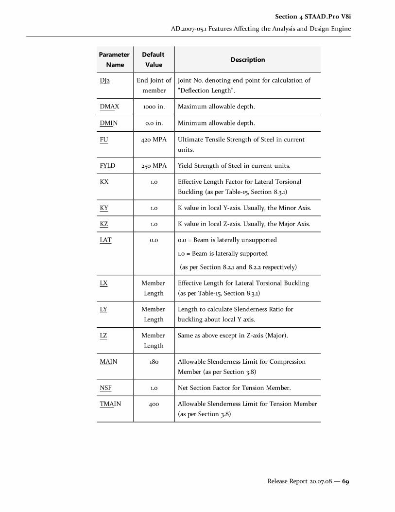
ParameterName
DefaultValue
Description
DJ2 End Joint ofmember
Joint No. denoting end point for calculation of"Deflection Length".
DMAX 1000 in. Maximum allowable depth.
DMIN 0.0 in. Minimum allowable depth.
FU 420 MPA Ultimate Tensile Strength of Steel in currentunits.
FYLD 250 MPA Yield Strength of Steel in current units.
KX 1.0 Effective Length Factor for Lateral TorsionalBuckling (as per Table-15, Section 8.3.1)
KY 1.0 K value in local Y-axis. Usually, the Minor Axis.
KZ 1.0 K value in local Z-axis. Usually, the Major Axis.
LAT 0.0 0.0 = Beam is laterally unsupported
1.0 = Beam is laterally supported
(as per Section 8.2.1 and 8.2.2 respectively)
LX MemberLength
Effective Length for Lateral Torsional Buckling(as per Table-15, Section 8.3.1)
LY MemberLength
Length to calculate Slenderness Ratio forbuckling about local Y axis.
LZ MemberLength
Same as above except in Z-axis (Major).
MAIN 180 Allowable Slenderness Limit for CompressionMember (as per Section 3.8)
NSF 1.0 Net Section Factor for Tension Member.
TMAIN 400 Allowable Slenderness Limit for Tension Member(as per Section 3.8)
Section 4 STAAD.Pro V8i
AD.2007-05.1 Features Affecting the Analysis and Design Engine
Release Report 20.07.08 — 69

ParameterName
DefaultValue
Description
PROFILE None Used in member selection.
See Section 5.47.1 of the TechnicalReference Manual for details.
PSI 1.0 Ratio of the Moments at the ends of the laterallyunsupported length of the beam
0.8 = where Factored AppliedMoment and Tension can varyindependently
1.0 = For any other case.
(as per Section 9.3.2.1)
RATIO 1.0 Permissible ratio of the actual to allowablestresses.
TRACK 0 Controls the levels of detail to which results arereported.
0 = Minimum detail
1 = Intermediate detail level
2 = Maximum detail
Note: *Top and Bottom represent the positive and negative side of the local Y axis (local Zaxis if SET Z UP is used).
AD.2007-05.1.3 Eurocode 3 Includes National Annex
Purpose
A number of countries that have signed up to the replace their current steel design standardswith the Eurocode, EN 1993-1-1:2005, known commonly as Eurocode 3, have published theirNational Annex documents. These documents make small changes to the base document andSTAAD.Pro has been updated to incorporate some of these National Annex documents. Currently,the Dutch and Norwegian National Annexes have been added to the STAAD.Pro engine.
Description
A new parameter, NA, that sets the default material gamma factors and any additional changesoutlined in the country specific National Annex such as specific equations or methods.
70 — STAAD.Pro V8i (SELECTseries 3)
Chapter — 4
AD.2007-05.1 Features Affecting the Analysis and Design Engine

The output file printout has been updated to indicate which National Annex (if any) has beenused in a code check / select process. (For all TRACK settings)
Note: This Eurocode 3 design code is secured using the ‘Eurocode Design’ code pack.
In order to include additional check specified by a National Annex:
1. From the Modeling > Design > Steel tab, select EN 1993-1-1:2005 from the current code list.
2. Click the Define Parameters… button to launch the Design Parameters dialog.
3. Select the parameter NA from the list.
4. Select the radio button for the National Annex you wish to use; or leave as Basic in order touse EC3 without additional checks.
5. Click the Add button to add the NA parameter to the code check.
6. Click Close to dismiss the dialog once parameter definitions are complete.
A design performed to the new Eurocode 3 National Annex is displayed in the output file (*.ANL)with the following header, in addition to the base EC3 output:
Section 4 STAAD.Pro V8i
AD.2007-05.1 Features Affecting the Analysis and Design Engine
Release Report 20.07.08 — 71

Note: The previous, development edition of Eurocode 3 is included as the Code EN3 DD.
General Format
The format of the Eurocode 3 National Annex is as follows:
CODE EN 1993-1-1:2005
NA f1
{Code parameters: See Eurocode 3 in International Codes section}
Where: f1 represents the number designation for a specific country's National Annex:
NA Value Country
0 None. This value representsusing the base code only, withno national annex changes oradditions (default).
1 British (currently inactive inSTAAD.Pro)
2 Dutch
3 Norwegian
Numerical code for Eurocode National Annex
AD.2007-05.1.4 Eurocode 8
Purpose
Eurocode 8: Part 1 [EN 1998-1-1:2004] contains specific requirements and recommendations forbuilding structures that are to be constructed in seismic regions. Essentially, these fundamental
72— STAAD.Pro V8i (SELECTseries 3)
Chapter — 4
AD.2007-05.1 Features Affecting the Analysis and Design Engine

requirements have been provided to ensure that the structures can sustain the seismic loadswithout collapse and also – where required – avoid suffering unacceptable damage and cancontinue to function after an exposure to a seismic event.
As with all Eurocodes, a National Annex Document should accompany the use of Eurocode 8 ineach of the European nations.
Description
a) Structure Modeling
To perform the geometry checks per Eurocode 8, STAAD.Pro must first calculate the center ofmass for each defined floor. Specifying a response spectrum loading accomplishes this.
Note: The EC8 response spectrum load must be specified in the model in order to perform anyfurther checks, design, or detailing per Eurocode 8.
From the Modeling > General > Load & Definition tab:
1. Select the load case where the EC8 seismic response spectrum definition will be added.
2. Click Add… to open the Add New Load Items box.
3. Select Response Spectra > Response Spectrum in the Load Items list.
4. Choose EURO (EC8) - 2004 from the Code list.
5. Set Response Spectrum options.
6. Click Add to add the new response spectrum to the current load case.
Section 4 STAAD.Pro V8i
AD.2007-05.1 Features Affecting the Analysis and Design Engine
Release Report 20.07.08 — 73

See also 5.32.10.1.2 Response Spectrum Specification per Eurocode 8.
Note: Floor height is determined by the program as a joint where one or more beams framein a column.
b) Analysis
All the analysis methods for design and evaluation of the performance of a structure mentionedin Eurocode, as listed in the following, have already been implemented in STAAD.Pro:
l Linear static (called “Lateral force method”)
l Linear modal response spectrum analysis
l Non-linear static analysis (push-over analysis)
l Non-linear dynamic analysis(Time-history analysis)
Note: In order to make use of the EC8 response spectrum load, a linear modal responsespectrum analysis should be used. This is required to locate the center of mass which isneeded to perform the associated geometry checks.
74 — STAAD.Pro V8i (SELECTseries 3)
Chapter — 4
AD.2007-05.1 Features Affecting the Analysis and Design Engine

Loads are distributed by element stiffness to all members during analysis. Thus, for the purposes ofEurocode 8, all members are assumed to be "primary seismic" elements.
Note: Eurocode 8 requires the use of cracked section stiffness when considering concretebuildings, which however is lacking in the current analysis engine. This can be overcome byusing a section reduction factor as suggested in the code. The current version of STAAD.Prohas a “section reduction factor” that can be used for this purpose.
c) Post-Processing
New Post-Processing Mode “Earthquake” Added
The “Earthquake” mode has been provided to allow the user to check if the structure conforms tothe basic geometric recommendations made in EC8. This mode is in addition to the normal postprocessing mode which gives the various analysis results. These checks are intended to give theuser a ‘feel’ for the structure and are not mandatory to proceed to the design phase.
This mode will be activated only if the analysis has been successful and if user has the rightprivileges to access the EC8 module.
Note: The program assumes y as vertical and that seismic forces act in the global x and zdirections.
These Earthquake > Eurocode 8 checks have been further classified into the following tabs:
l Stiffness Checks - This set of checks is to enables you to judge whether the stiffness char-acteristics of the structure meet the recommendations set by EC 8. This implementationwill:
i. Display the center of mass and center of stiffness graphically for each floor to informyou of some inherent eccentricities and their variation along the height of the build-ing.
ii. Calculate the total stiffness of every story in each direction and provide you with aratio of the stiffnesses in the two directions. This aides you to judge whether thestructure conforms to the condition in EC8 that the stiffness should be similar inboth directions.
iii. Check to see if there are any soft stories in the structure and will highlight them inthe GUI. A soft story is defined as a story that has a stiffness in a particular directionthat is less than 70% of the stiffness of the story above.
Section 4 STAAD.Pro V8i
AD.2007-05.1 Features Affecting the Analysis and Design Engine
Release Report 20.07.08 — 75

Note: The stiffness of only the vertical elements are considered while working out the totalstiffness of a storey in a particular direction as the seismic loads are primarily resisted by thevertical elements in a structure.
l Plan regularity - This set of checks is to enable you to be able to classify the building asbeing 'regular in plan.' Checks will be performed and the results will be displayed graph-ically in the GUI. The program primarily checks for the main three plan regularity con-ditions set out in EC-8 viz.
i. Checks for re-entrant corners in floor slabs – The program performs checks on eachfloor slab and reports whether the condition set out in EC-8 for re-entrant cornershas been satisfied.
ii. Check for slenderness of structure – The program calculates a ‘slenderness ratio’ forthe structure based on the maximum dimensions on plan and reports whether theEC-8 criteria are satisfied.
iii. Checks for torsional radius: - The program calculates the torsional radius for eachfloor and checks against the conditions set out in EC-8.
l Elevation Regularity - This set of checks is to enable the user to be able to classify the build-ing as a 'regular in elevation' structure. Checks will be performed and the results will bedisplayed graphically in the GUI.
d) Member Design
Perform basic design per EC2
A preliminary design per Eurocode 2 must be made for all concrete members prior to detailingand design per Eurocode 8. Once this is completed, click on the Earthquake tab in the RCDesigner module. The Collapse Check Setup dialog will launch.
Seismic Design and Detailing per EC8
76— STAAD.Pro V8i (SELECTseries 3)
Chapter — 4
AD.2007-05.1 Features Affecting the Analysis and Design Engine

1. With EC8 - 2004 selected in the Design Code list, specify the National Annex. Currently,only the UK Annex is available.
2. Specify Medium (DCM) or High (DCH) in the Ductility level list. Low ductility (DCL) doesnot require additional Eurocode 8 checks and therefore is not included.
3. Specify the load case containing seismic loads for use with design checks.
4. Specify the Structural Type in the list. Currently, only Framed/ Dual/Coupled Wall Systemsare supported in RC Designer.
5. Select if you wish to Check reinforcement for detailing rules for ductility per EC8.
6. Specify a Curvature ductility factor to be used for column checks. If not specified, thedefault value is taken as unity (1).
7. Click Check Now to perform all design and detailing checks.
In order for EC8 checks to be performed, a member must have passed all EC2 checks in the initialdesign step. To also help identify issues in design or detailing, if one step of checks fails for amember, further checks will not be performed on that member.
The program will first check that all materials in the design brief are satisfactory. Then, momentcapacity of beams and columns are evaluated and compared. EC8 stipulates that columns musthave a moment capacity of 1.30 times the sum of the moment capacity of beams framing at thatjoint. This ensures beams are the initial failure mode.
Note: Deflection checks are performed for individual members only.
AD.2007-05.1.5 AIJ Concrete Design Update
Purpose
An old version of Japanese concrete code based on the AIJ standard for structural calculation ofReinforced Concrete Structures (1985 edition) was previously implemented in STAAD Pro batchmode design. Recently, critical errors in the column design and beam design were discovered andcorrected. In addition, the AIJ concrete design has been udpated to incorporate the latest AIJstandard for structural calculation of Reinforced Concrete Structures (1991 edition). .
Description
Generally, this implementation will be invisible to the user. The 1985 edition of the AIJ has beencompletely replaced by the 1991 edition for the design of concrete members per the AIJ. Theexisting commands as described in the International Codes section of this document are applicableto the 1991 edition.
AD.2007-05.2 Features Affecting the Concrete Design Mode
Section 4 STAAD.Pro V8i
AD.2007-05.2 Features Affecting the Concrete Design Mode
Release Report 20.07.08 — 77

An existing feature has been modified in the RC Designer section of the program, also known asthe Concrete Design mode. This is explained in the following pages.
AD.2007-05.2.1 RC Designer Member and Envelope Import
Purpose
The ability to create physical members in STAAD.Pro has been introduced since the originalimplementation of the RC Designer. Previously these members did not get carried through intothe RC Designer, thus requiring the extra step of re-creating these members, and possibleconfusion if the same member numbers were not used.
Similarly, load case/combination envelopes were not carried through into the RC Designer,requiring extra care in identifying which load cases were being considered when examining theoutput.
The physical member definitions are now passed through to the RC Designer along with theother structural data from STAAD.Pro. Envelope definitions are also carried through andexamined to see if they contain any dynamic loading for which it may be inappropriate to use theanalysis results directly.
Description
Generally, this implementation is invisible to the user. Physical member assignments made in theSTAAD.Pro Modeling mode will be carried over to the RC Designer (Concrete Design mode). Ifexisting designs are re-examined, the user may be warned if member numbers or constitution (interms of beam elements included) differ between the STAAD.Pro Modeling mode and the RCDesigner definitions, and the option is given to delete the RC Designer members with theirresults. For envelopes, the user is prompted if the envelope numbers or constitution differbetween RC Designer and STAAD.Pro Modeling mode.
Additionally, a warning may be presented to the user is any envelope incorporates a dynamic loadcase. This is because the dynamic load cases in STAAD.Pro only produce positive values formoments and forces, even though it is understood that the loading actually reverses. Concretedesign based on an envelope of positive forces only would be seriously under-reinforced.
78— STAAD.Pro V8i (SELECTseries 3)
Chapter — 4
AD.2007-05.2 Features Affecting the Concrete Design Mode

STAAD.Pro V8i What's New in Release 20.07.05 – 79
Section 5
STAAD.Pro V8i(release 20.07.04)
IntroductionThe Software Release Report for STAAD.Pro V8i contains detailed information on additions and changesthat have been implemented since the release of STAAD.Pro 2007 build 03. This document should be readin conjunction with all other STAAD.Pro manuals, including the Revision History document.
AD.V8i.0 New Features Affecting the General Program
This section describes features that have been added that affect the general behavior of the STAAD.Proapplication.

80 – STAAD.Pro V8i What's New in Release 20.07.05
AD.V8i.0 New Features Affecting the General Program
AD.V8i.0.1 ProjectWise Integration
ProjectWise is an engineering project team collaboration system which is used to help teams improvequality, reduce rework, and meet project deadlines. One of the major pieces of functionality provided byProjectWise is an Integration Server which allows data to be managed and shared across a distributedenterprise.
STAAD.Pro has been enhanced so that the model STD data file can be managed on a ProjectWise server.
Description
Four integration functionalities have been added. These are
l Open a STAAD model from a ProjectWise repository.
l Save a local STAAD model into a ProjectWise repository.
l Update an existing model from ProjectWise.
l Review model properties (meta-data) which has been opened from a ProjectWise repository.
Note that access to all of these functionalities is available from ProjectWise sub-menu under the generalFile menu described below.
ProjectWise repository
Installation and management of a ProjectWise server is beyond the scope of this document and should beobtained from the ProjectWise installation.
ProjectWise client
A local ProjectWise client should be installed which allows access to ProjectWise repositories.
STAAD.Pro
When STAAD.Pro is launched, the option to open and check out a STAAD.Pro STD file from aProjectWise repository is made available from the Project Tasks on the Start Page thus:-

STAAD.Pro V8i What's New in Release 20.07.05 – 81
This is also available from the File menu while still on the Start Page prior to opening a model:-
If a suitable ProjectWise client is not installed, then the link on the Start Page is shown as unavailablewith a red line through the icon thus:-
Login
As authentication is required to access files stored on a ProjectWise repository, a login dialog allows therequired details to be entered either with specific user credentials or by using the current windows logincredentials thus:-
Files that are accessed from a ProjectWise server are ‘Checked Out’ and stored locally during theSTAAD.Pro session until the file is closed and then it is returned to the server.
Opening a STAAD Model from a ProjectWise repository
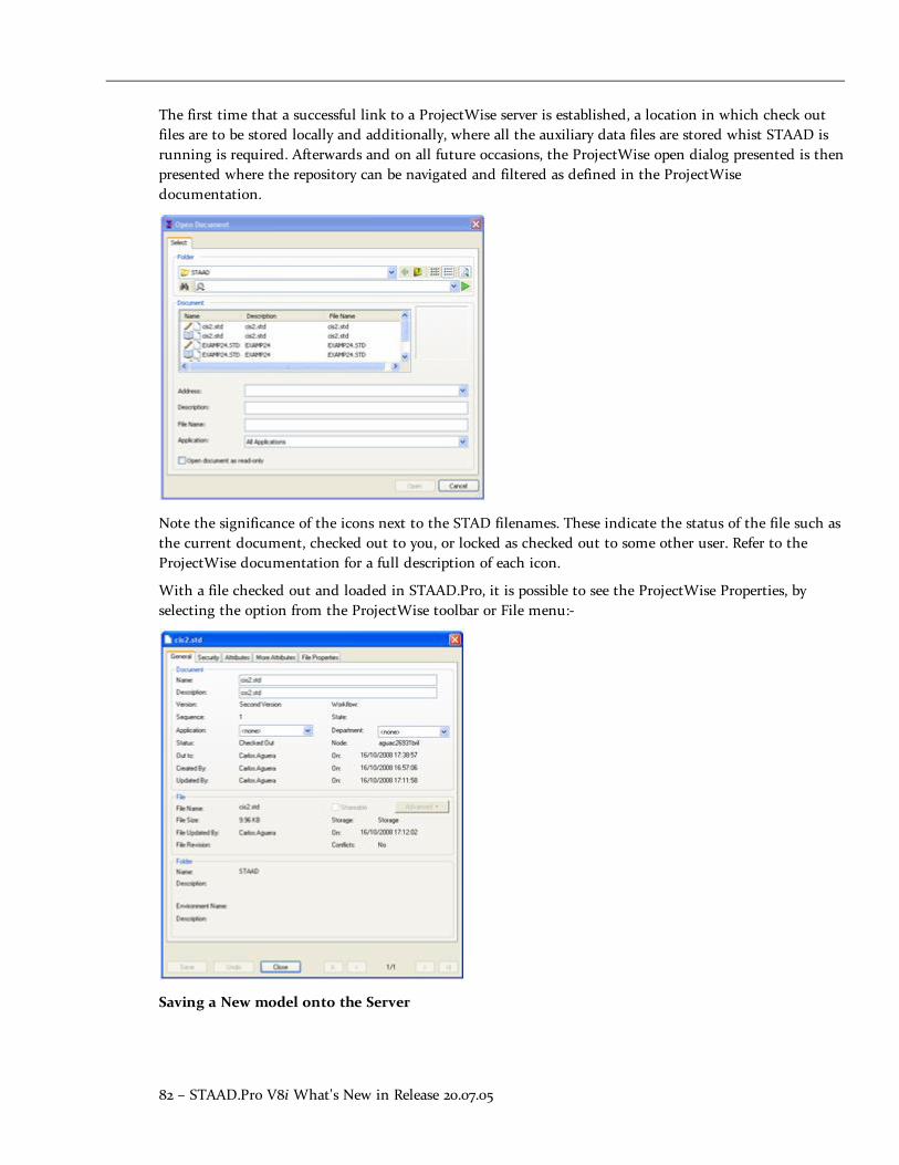
82 – STAAD.Pro V8i What's New in Release 20.07.05
The first time that a successful link to a ProjectWise server is established, a location in which check outfiles are to be stored locally and additionally, where all the auxiliary data files are stored whist STAAD isrunning is required. Afterwards and on all future occasions, the ProjectWise open dialog presented is thenpresented where the repository can be navigated and filtered as defined in the ProjectWisedocumentation.
Note the significance of the icons next to the STAD filenames. These indicate the status of the file such asthe current document, checked out to you, or locked as checked out to some other user. Refer to theProjectWise documentation for a full description of each icon.
With a file checked out and loaded in STAAD.Pro, it is possible to see the ProjectWise Properties, byselecting the option from the ProjectWise toolbar or File menu:-
Saving a New model onto the Server
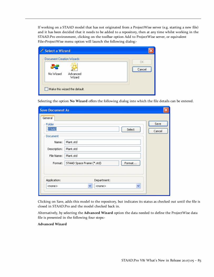
STAAD.Pro V8i What's New in Release 20.07.05 – 83
If working on a STAAD model that has not originated from a ProjectWise server (e.g. starting a new file)and it has been decided that it needs to be added to a repository, then at any time whilst working in theSTAAD.Pro environment, clicking on the toolbar option Add to ProjectWise server, or equivalentFile>ProjectWise menu option will launch the following dialog:-
Selecting the option No Wizard offers the following dialog into which the file details can be entered.
Clicking on Save, adds this model to the repository, but indicates its status as checked out until the file isclosed in STAAD.Pro and the model checked back in.
Alternatively, by selecting the Advanced Wizard option the data needed to define the ProjectWise datafile is presented in the following four steps:-
Advanced Wizard
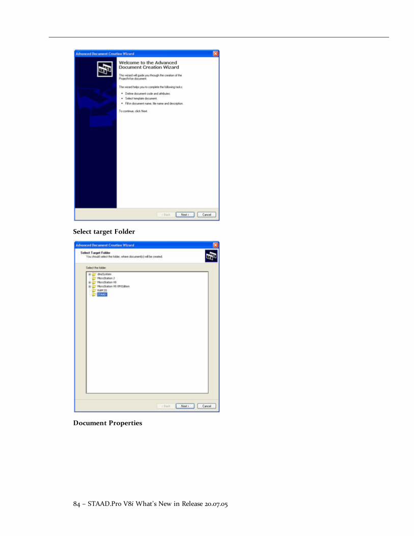
84 – STAAD.Pro V8i What's New in Release 20.07.05
Select target Folder
Document Properties

STAAD.Pro V8i What's New in Release 20.07.05 – 85
Create the document
Creates the document and marks it as checked out until the file is closed and checked in to the server.
Saving changes of a Checked Out model Back on the Server
When a model is checked out from a ProjectWise server, selecting Save or Save As, only maintains a localcopy of the model. There are two methods available to update a checked out model. Firstly, during aSTAAD.Pro session, it is possible at any time to save any changes back on the server by selecting theUpdate Server Copy icon from the ProjectWise toolbar or from the File>ProjectWise menu.

86 – STAAD.Pro V8i What's New in Release 20.07.05
First save updates to the file locally. If not, then this will be prompted. Then the following dialog isdisplayed which allows a comment to be added to this model, thus:-
The file remains checked out and can be continued to be worked on.
The second method is automatically generated when a checked out model is closed. This launches theCheck In dialog that displays the file(s) that are to be checked in and provides four actions:-
Check In
This copies the local version of the STAAD model back to the server and releases it so that it isavailable for others to modify. If the option Create New Version is selected, then a new copy of thefile is created on the server which becomes the current version of the model. The status of thechecked out model is changed to read only on the server and can be used as a reference to a stagein the development of the model.
Update Server Copy

STAAD.Pro V8i What's New in Release 20.07.05 – 87
This updates the model on the server with the current local model, but does not change its statuswhich remains as checked out.
Free
This changes the status of the model as checked in which allows other users to take control andcheck out the model, but does not update the server model. Thus local changes will be discarded
Cancel
This cancels any change to the status of the model or the model itself on the server.
Menu
The commands that drive the ProjectWise integration are defined in the main File menu thus:-
File>ProjectWise>
The Add... command is available when using a locally opened (not checked out fromProjectWise), which allows the current model to be saved into a ProjectWise repository.
The Open… command is available when a suitable ProjectWise client has been installed to allowaccess to a repository from which to check out a STD file.
The Update Server Copy command is available when working on a checked out file and thechanges made on the model can be
Toolbar
A new toolbar named ProjectWise has been added that duplicates the commands from theFile>ProjectWise menu, thus:-
Notes:
1. For more details on ProjectWise refer to the ProjectWise client installation documentation.
2. This functionality requires access to a version V8i or greater of ProjectWise.
AD.V8i.0 New Features Affecting the General Program
AD.V8i.0.2 CIS/2 Update
The STAAD.Pro tool to import and export models with the CIS/2 translator has been enhanced to workwith international models and transferring models into 3D modeling such as SmartPlant 3D.

88 – STAAD.Pro V8i What's New in Release 20.07.05
Description
The CIS/2 (CimSteel Integration Standard, Version 2) allows for the transfer of steel models using aprescribed data standard in the STEP (Part 21) format. These files can contain different models includinganalysis models. The STAAD.Pro CIS/2 translator only operates on the analysis model within the file.Whilst STAAD.Pro has supported a wide range of the steel sections that this standard can support, thisenhancement allows a far greater range of sections to be imported/exported with this tool.
Import
The CIS/2 import can be initiated after starting a new model and before creating any model data,selecting the menu option,
File>Import…
Selecting the CIS/2 option and clicking on the ‘Import’ button allows selection of a suitable STEP file.This file is a text file and will be similar to the following extract:
ISO-10303-21;HEADER;/* Generated by software containing ST-Developer* from STEP Tools, Inc. (www.steptools.com)*/ FILE_DESCRIPTION(/* description */ ('CIS2 Export File'),/* implementation_level */ '2;1');FILE_NAME(/* name */ 'model',/* time_stamp */ '2007-01-08T17:00:33+00:00',/* author */ (''),/* organization */ (''),/* preprocessor_version */ 'ST-DEVELOPER v9',/* originating_system */ 'STAAD.Pro 2007',/* authorisation */ '');FILE_SCHEMA (('STRUCTURAL_FRAME_SCHEMA'));ENDSEC;DATA;#10=LOAD_COMBINATION_OCCURRENCE(1.39999997615814,#13,#264);#11=LOAD_COMBINATION_OCCURRENCE(1.39999997615814,#13,#265);#12=LOAD_COMBINATION_OCCURRENCE(1.60000002384186,#13,#266);#13=LOADING_COMBINATION('ULS',$,#2511);#14=LOAD_ELEMENT_DISTRIBUTED_CURVE_LINE(#265,'Member19UDLLoad1',$,#1089,$,$,.F.,.GLOBAL_LOAD.,.TRUE_LENGTH.,#214,#214,#64);#15=LOAD_ELEMENT_DISTRIBUTED_CURVE_LINE(#265,'Member20UDLLoad1',$,#1090,

STAAD.Pro V8i What's New in Release 20.07.05 – 89
Once a file has been selected, the data is ready to be imported with the CIS/2 import tool thus:-
Clicking the Import button then runs the model import where the CIS/2 file is processed and the analysismodel data is extracted to form the STAAD.Pro model.
Note that as the CIS/2 file is being processed, a log file which identifies the data that has been utilized inthe STAAD model is produced and displayed which can be saved as a text file for future reference.
Export
The CIS/2 Export is available for any model that has been created as an option in the menu itemFile>Export…

90 – STAAD.Pro V8i What's New in Release 20.07.05
Selecting the CIS/2 option and clicking on the ‘Export’ button allows the definition of a suitable STEPfilename and folder to locate it. Once again the CIS/2 tool is presented, this time with an Export Modelbutton at the bottom which when clicked creates the STP file.
Once again, when the export has completed, the user can save the log file which is produced as the modelis converted into the STEP format.

STAAD.Pro V8i What's New in Release 20.07.05 – 91
Enhancements
The STAAD.Pro CIS/2 import now recognizes sections defined from standard databases such as thosedefined in Japanese, British, Indian, Australian and European tables.
The import/export has been enhanced to support the ability of STAAD.Pro to create double sections, suchas back to back angles and channels or double wide flange sections. Additionally, it now supports thecreation of T sections which are defined in STAAD.Pro as a wide flange section that is split at mid height.
Although CIS/2 has been developed for the processing of steel models, the STAAD.Pro translator will nowsupport the transfer of prismatic properties normally associated with concrete sections. This means thatsections defined as PRISMATIC in a STAAD.Pro model will be included in exported STP file and can beimported if they exist.
AD.V8i.1 Features Affecting the Pre-Processor (Modeling Mode)
Several new features have been added and existing features have been modified in the pre-processorsection of the program, also known as the Modeling Mode. These are explained in the following pages.
AD.V8i.1 Features Affecting the Pre-Processor (Modeling Mode)
AD.V8i.1.1 ASME NF Steel Design Codes
The design of steel sections according to the requirements in the American Society of MechanicalEngineers (ASME) specifications, Rules for the Construction of Nuclear Power Plant Components, SectionIII – Subsection NF has been implemented and the steel design page has been updated to allow thedesign parameters to be defined and assigned.
The design requirements for the following years have been added:-
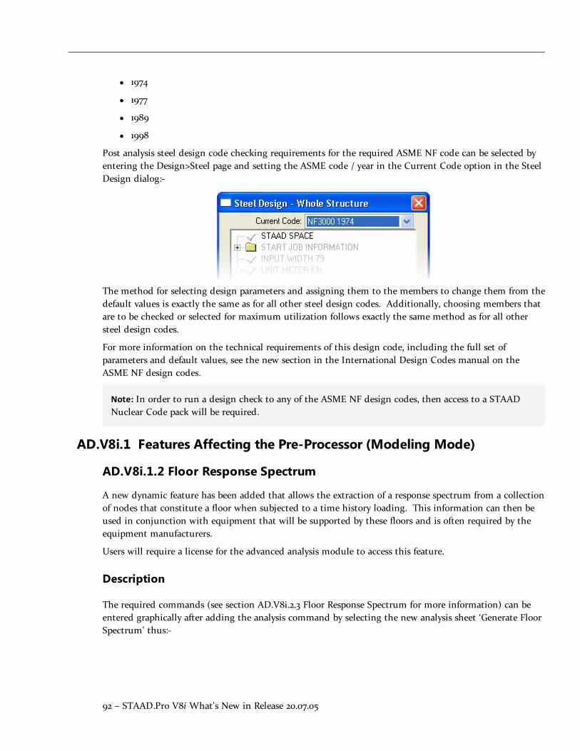
92 – STAAD.Pro V8i What's New in Release 20.07.05
l 1974
l 1977
l 1989
l 1998
Post analysis steel design code checking requirements for the required ASME NF code can be selected byentering the Design>Steel page and setting the ASME code / year in the Current Code option in the SteelDesign dialog:-
The method for selecting design parameters and assigning them to the members to change them from thedefault values is exactly the same as for all other steel design codes. Additionally, choosing members thatare to be checked or selected for maximum utilization follows exactly the same method as for all othersteel design codes.
For more information on the technical requirements of this design code, including the full set ofparameters and default values, see the new section in the International Design Codes manual on theASME NF design codes.
Note: In order to run a design check to any of the ASME NF design codes, then access to a STAADNuclear Code pack will be required.
AD.V8i.1 Features Affecting the Pre-Processor (Modeling Mode)
AD.V8i.1.2 Floor Response Spectrum
A new dynamic feature has been added that allows the extraction of a response spectrum from a collectionof nodes that constitute a floor when subjected to a time history loading. This information can then beused in conjunction with equipment that will be supported by these floors and is often required by theequipment manufacturers.
Users will require a license for the advanced analysis module to access this feature.
Description
The required commands (see section AD.V8i.2.3 Floor Response Spectrum for more information) can beentered graphically after adding the analysis command by selecting the new analysis sheet ‘Generate FloorSpectrum’ thus:-

STAAD.Pro V8i What's New in Release 20.07.05 – 93
This command should follow immediately the definition of the analysis and will require defined groupsof nodes which need to be defined first.
The following displays the layout of this sheet:-
Note that the each line of settings constitutes one floor which can have one or more floor groupsassigned. The resulting response spectra will be based on the collective responses of all the nodes in theselected groups.
Once the required options have been set, click on the Add button to add the command set to the modelwhich should appear in the Analysis Window thus:-

94 – STAAD.Pro V8i What's New in Release 20.07.05
Once the command has been added and the file saved, the analysis can be run which will generate a newsub-page in the Post-Processing Mode in the Dynamics Page called Floor Spectrum:-

STAAD.Pro V8i What's New in Release 20.07.05 – 95
Entering this page, STAAD.Pro will display the floor spectrum thus:-
To change graphs to that of another selection of node groups or damping ratio, then
select the required set from the drop list in the Response Spectrum Table.
The graph is initially set to display the results on a log/log graph. This can be changed to a linear graphby right clicking on the graph and selecting the ‘Linear Graph’ option. Additionally, the calculated pointson the graph can be added by again right clicking on the graph and selecting the option ‘Show Points’.
The data that has defined the graph can also be exported to a text file and used in a third partyapplication by right clicking on the graph and selecting the option ‘Save Data in Text File…’
AD.V8i.1 Features Affecting the Pre-Processor (Modeling Mode)
AD.V8i.1.3 Russian Wind Loading
The wind loading as defined in the design code SNiP 2.01.07–85 “Loads and Actions” added in this versionof STAAD.Pro can be added graphically to the model by modifications in the Loads Page.
Description
There are two areas where the graphical user interface has been updated:

96 – STAAD.Pro V8i What's New in Release 20.07.05
Wind Load Definition dialog box
The dialog has been updated to allow the entry of the required parameters for a Russian Wind Loaddefinition thus:-
This will create a definition which can be added to a wind load case.
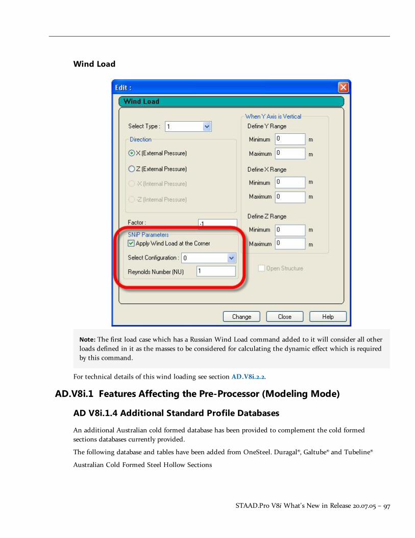
STAAD.Pro V8i What's New in Release 20.07.05 – 97
Wind Load
Note: The first load case which has a Russian Wind Load command added to it will consider all otherloads defined in it as the masses to be considered for calculating the dynamic effect which is requiredby this command.
For technical details of this wind loading see section AD.V8i.2.2.
AD.V8i.1 Features Affecting the Pre-Processor (Modeling Mode)
AD V8i.1.4 Additional Standard Profile Databases
An additional Australian cold formed database has been provided to complement the cold formedsections databases currently provided.
The following database and tables have been added from OneSteel. Duragal®, Galtube® and Tubeline®
Australian Cold Formed Steel Hollow Sections

98 – STAAD.Pro V8i What's New in Release 20.07.05
Circular Hollow Sections:
l Galtube Plus®, 26.9mm to 76.1mm diameter
l Tubeline, grades C250L0 (AS1163) and 350L0 (AS1163), 21.3mm to 457.0mm
Rectangular Hollow Sections
l Duragal®, grade C450L0 (AS1163), 50x20mm to 150x50mm
l Galtube Plus®, grade C350L0, 50x20mm to 75x25mm
l Tubeline®, grade C350L0 (AS1163), 50x20mm to 250x150mm
Square Hollow Sections
l Duragal®, grade C450L0 (AS1163), 20x20mm to 100x100mm
l Galtube Plus®, grade C350L0, 20x20mm to 65x65mm
l Tubeline®, grade C350L0 (AS1163), 13x13mm to 250x250mm
AD.V8i.2 Features Affecting the Analysis and Design Engine
The following section describes the new features have been added to the analysis and design engine andexisting features that have been updated or modified.
AD.V8i.2 Features Affecting the Analysis and Design Engine
AD.V8i.2.1 ASME NF
The design of steel sections according to the requirements in the American Society of MechanicalEngineers (ASME) specifications, Rules for the Construction of Nuclear Power Plant Components, SectionIII – Subsection NF has been implemented and the steel design page has been updated to allow thedesign parameters to be defined and assigned.
The design requirements for the following years have been added:-
l 1974
l 1977
l 1989
l 1998
For the list of parameters and commands including the default values, please refer to the InternationalDesign Codes manual, section 16.

STAAD.Pro V8i What's New in Release 20.07.05 – 99
For each steel member that is checked, the following checks are performed according to the clauses forthat year:-
1. Slenderness check
2. Tension
3. Compression
4. Bending (a) About major axis, (b) About major axis
5. Shear
6. Combined Stresses
AD.V8i.2 Features Affecting the Analysis and Design Engine
AD.V8i.2.2 Russian Wind Loading
The wind loading commands have been enhanced to allow the creation of wind loading as defined in thein Russia by the design code SNiP 2.01.07–85 “Loads and Actions”.
The basic quantity in the wind loading is the characteristic (normative in Russian terminology) windpressure. The reference wind velocity pressure corresponds to a 10-minute time-averaged velocity pressureat 10-metres height in a flat terrain, based on a 5-year return period. This wind pressure is the staticcomponent of the wind load. The total wind pressure consists of static and fluctuating components. If thestructure is sufficiently flexible, according to the code provisions, the dynamic structural response to thefluctuating wind component must be taken into account.
The updated wind loading commands automatically perform both the aerodynamic and structural loadanalysis of vibration-susceptible buildings and structures.
The wind loading commands have been updated to support the wind loading as defined in the Russiandesign code. This requires the creation of the following commands.
General Format
There are three parts to creating a Russian wind load on a STAAD Model.
Definition of the wind load requirements
This should occur before the definition of the first load case
DEFINE WIND LOAD
TYPE j
SNIP PRESSURE f1 TERRAIN { A | B | C } CLASSIFICATION { 1 | 2 | 3 }
EXPOSURE e1 { JOINT joint-list | YRANGE f2 f3 }
Repeat EXPOSURE command up to 98 times.
Where:
j = wind load system type number (integer)

100 – STAAD.Pro V8i What's New in Release 20.07.05
f1 = the characteristic value of wind pressure, always positive. All values of the pressurewithin the range of corresponding SNiP table are valid.
TERRAIN is terrain roughness category:
A. Costal Zone
B. Urban
C. Large City according to the SNiP classification.
CLASSIFICATION:
1. for prismatic building structures,
2. for general concrete structures,
3. for general open framed steel structures.
e1, e2 … em = multiplying wind pressure influence areas. For stick-type structures withcompact members aligned along the vertical line (e.g, chimneys, elevated water tanks),influence areas are set to unity, and exposure factors are aerodynamic diameters of members.
joint-list = Joint list associated with Exposure Factor (joint numbers or “TO” or “BY”) orenter only a group name.
If the command EXPOSURE is not specified or if a joint is not listed in an Exposure, the exposure factor forthose joints is chosen as 1.0.
Application of the wind load definition within a load case
Each load case which is to include a Russian wind load specification should include the following:
LOAD i
WIND LOAD { X | Z } (f) ( OBLIQUE ) CONFIGURATION if ( NU fNU )
TYPE j { XRANGE f1 f2 | YRANGE f1 f2 | ZRANGE f1 f2 | LIST member-list | ALL }
Where:
X or Z defines the wind direction
f = wind pressure factor. A negative value is used to define a reverse wind direction
if = configuration parameter for prismatic buildings, range 0-12;
0. prismatic building structure - Rectangular building- Outstanding architecturaldetails on the left façade.
1. prismatic building structure - Rectangular building- Both side façades are smooth
2. prismatic building structure - Rectangular building- Outstanding architecturaldetails on the right façade
3. prismatic building structure - Rectangular building- Outstanding architecturaldetails on both side façades

STAAD.Pro V8i What's New in Release 20.07.05 – 101
4. prismatic building structure - Rectangular building- Triangular building
5. prismatic building structure - Rectangular building- Rhombic building
6. prismatic building structure - Rectangular building- Number of vertices of polygonalbuilding, not more than 12
7. prismatic building structure - Less than 3 — rectangular building
8. prismatic building structure - 3 — triangular
9. prismatic building structure - 4 — rhombic
10. prismatic building structure - More than 4 — polygonal
11. framed RC structure
12. lattice steel structure
it is ignored for non-building structures, but cannot be omitted from the command
fNU = wind pressure correlation coefficient. If parameter is omitted or is exactly 1, acomputed value is used instead. For rectangular buildings, the correlation coefficient isalways calculated automatically, thus any specified value will be ignored.
Additionally, as part of the load force is determined from the dynamic behavior of themodel, the first load case that includes a Russian Wind Load specification also needs toinclude all the masses that can cause the structure to vibrate from which a dynamic analysiswill be used to extract the mode shapes.
Note: This in effect becomes a dynamic load case, thus if the effects of these forces are tobe combined with the effects of static load cases, then this should be done using aLOAD COMBINATION which references the required load case results with theappropriate factors.
Cut-Off Frequency or Mode Shape
As the analysis will requires extraction of eigen solutions to determine the dynamic effects of the windloading, the number of modes to be used will also affect the results. Thus setting the command CUT OFFFREQUENCY or CUT OFF MODE should be considered and specified as required prior to the definitionof the load cases.
If the cut-off command is omitted, six mode shapes are computed by default.
For more information on these commands, see the Technical Reference manual section 5. 30.1 Cut-OffFrequency, Mode Shapes or Time.
Example
DEFINE WIND LOAD
TYPE 1
SNIP PRESSURE 0.38 TERRAIN A CLASSIFICATION 1
EXP 0.5 JOINT 1 3 5 7 9 11

102 – STAAD.Pro V8i What's New in Release 20.07.05
*
LOAD 1 LOADTYPE WIND TITLE WIND LOAD IN THE +VE X DIRECTION
WIND LOAD X 1 CONFIG 0 NU 1 TYPE 1
* MASS MODEL REQUIRED IN FIRST WIND LOAD CASE
JOINT LOAD
3 TO 6 FZ 62.223
9 TO 12 FZ 62.223
*
LOAD 2 LOADTYPE WIND TITLE WIND LOAD IN THE –VE X DIRECTION
WIND LOAD X -1 CONFIG 0 NU 1 TYPE 1
* NO MASS MODEL OR ADDITIONAL LOADS IN THIS LOAD CASE
*
LOAD 3 LOADTYPE WIND TITLE WIND LOAD IN THE +VE Z DIRECTION
WIND LOAD Z 1 CONFIG 0 NU 1 TYPE 1
* NO MASS MODEL OR ADDITIONAL LOADS IN THIS LOAD CASE
*
LOAD 4 LOADTYPE WIND TITLE WIND LOAD IN THE –VE Z DIRECTION
WIND LOAD Z -1 CONFIG 0 NU 1 TYPE 1
* NO MASS MODEL OR ADDITIONAL LOADS IN THIS LOAD CASE
*
LOAD 10 LOADTYPE DEAD TITLE SELFWEIGHT LOAD CASE
SELF Y -1 ALL
*
LOAD COMBINATION 100 WIND PLUS SELFWEIGHT
1 1.0 10 1.0
Notes
a. This command cannot be used with models that have been defined with the SET Z UP command.
b. For more information on wind loading see sections 5.31.3 Definition of Wind Load and 5.32.12 Gen-eration of Loads of the Technical Reference Manual.
AD.V8i.2 Features Affecting the Analysis and Design Engine
AD.V8i.2.3 Floor Response Spectrum
The following commands have been added in order to allow the response spectrum of floors to beextracted from a time history analysis.

STAAD.Pro V8i What's New in Release 20.07.05 – 103
This command is used to specify the calculation of floor and/or joint spectra from time history results. The Floor Response Spectrum command must immediately follow an analysis command. That analysiscan only contain a single time history load case.
Refer to Section 5.32.10.3 of the Technical Reference manual details on the GENERATE FLOOR SPECTRUMcommand.
AD.V8i.3 Features Affecting the Post-Processing (Results Mode)
Several new features have been added and existing features have been modified in the post-processingsection of the program, also known as the Results Mode. These are explained in the following pages.
AD.V8i.3 Features Affecting the Post-Processing (Results Mode)
AD.V8i.3.1 Time History Animation
In order to visualize the displacement that occurs on a model during the application of a time historyload, a new toolbar icon has been added which allows the displacement at a specific time instance to bedisplayed.
The results toolbar has been updated to include a new option which is activated when the displacementdiagram icon has been clicked and the current load case contains time history loading:
For a time history load case the displacement that is displayed will be defined by the time instanceentered in the above edit box. Alternatively the time can be set from a sliding scale by clicking on thebutton with the down arrow icon which displays the following option setting:

104 – STAAD.Pro V8i What's New in Release 20.07.05
The slider scale is based on the overall time for which the time history analysis has been performed.
The displacement is produced at the time at which the slider arrow is dragged to and the mouse buttonreleased.
If the Apply Immediately option is selected, then the application will attempt to render the displacementdiagram dynamically as the slider is dragged up and down the scale of time. For large models this mayprove to be too demanding on the graphics system and left un-checked which means that thedisplacement diagram will be produced at the time step at which the slider arrow is released.
Note that the displacement diagram will be set to the scale as defined in the Scales sheet in the StructureDiagrams dialog box.
Additionally note that it is possible to view the time v displacement of individual nodes b clicking on theDynamics>Time-Disp in the post processing mode which is only available for models that include timehistory.
AD.V8i.3 Features Affecting the Post-Processing (Results Mode)
AD.V8i.3.2 Enhanced Plate Stress Results
In order to provide additional understanding of stress distribution in finite element models, STAAD.Prohas expanded the sets of results that can be reported for each element both in the Plate Centre StressTable and graphically using the Plate Stress Contour.
To view the results data of plate elements, enter the Post Processing (Results) Mode, and click on thePlate Contour Page on the left menu.
Plate Centre Stress Table
The new Combined Stresses sheet in the Plate Centre Stress table provides resolved stresses for the top(positive local Z) and bottom (negative local Z axis) surface for each plate element, referred to as the TopCombined Stresses and Bottom Combined Stresses respectively.

STAAD.Pro V8i What's New in Release 20.07.05 – 105
Note that if the sheet title Combined Stresses is not visible on the top of the table, then click on the rightarrows displayed on the left of the table header to scroll the table sheets which will display the title.
The combined stresses are calculated thus:
Top:
SXtop = SX + MX/S
SYtop = SY + MY/S
SXYtop = SXY + MXY/S
Bottom:
SXbottom = SX + MX/S
SYbottom = SY + MY/S
SXYbottom = SXY - MXY/S
Where:
S = t2/6 t
t = average plate thickness
Plate Stress Contour
The Plate Stress Contour sheet of the Diagrams dialog has been enhanced to allow visualization of thesestresses. The six new stress results are available in the Stress Type pull down menu thus:

106 – STAAD.Pro V8i What's New in Release 20.07.05
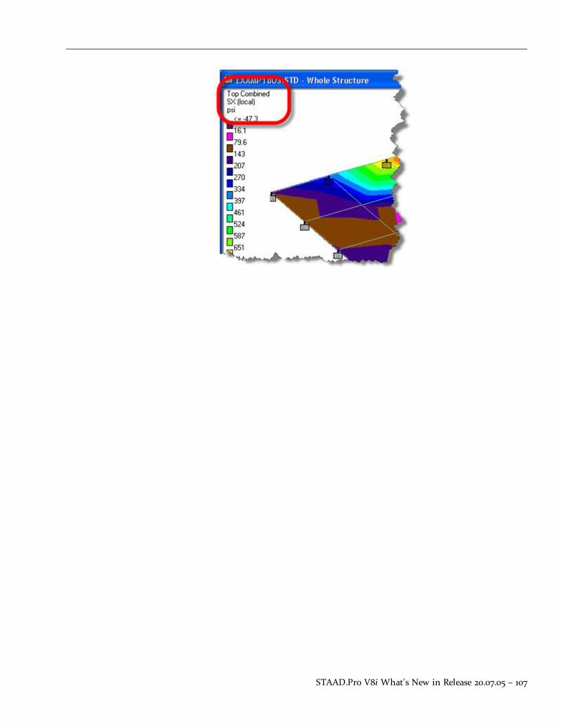
STAAD.Pro V8i What's New in Release 20.07.05 – 107


Technical SupportThese resources are provided to help you answer support questions:
l Service Ticket Manager — http://www.bentley.com/serviceticketmanager — Create andtrack a service ticket using Bentley Systems' online site for reporting problems or suggestingnew features. You do not need to be a Bentley SELECT member to use Service Ticket Man-ager, however you do need to register as a user.
l Knowledge Base — http://appsnet.bentley.com/kbase/— Search the Bentley Systemsknowledge base for solutions for common problems.
l FAQs and TechNotes — http://-communities.bentley.com/Products/Structural/Structural_Analysis___Design/w/Stru-ctural_Analysis_and_Design__Wiki/structural-product-technotes-and-faqs.aspx—Here you can find detailed resolutions and answers to the most common questions postedto us by you.
l Ask Your Peers — http://communities.bentley.com/forums/5932/ShowForum.aspx—Post questions in the Be Community forums to receive help and advice from fellow users.
Release Report 20.07.08 — 109

110 — (Undefined variable: Primary.ProductName)
Chapter 6

Index: 2.3 Floor Response Spectrum – Eigen
Index2
2.3 Floor Response Spectrum 92
A
Actions 95
AD.V8i.1.3 Russian Wind Loading 95
Add 80
Add button 93
Advanced Wizard 83
Although CIS 91
Analysis Window 93
Annexe Nationale a la NF EN 1993-1-1 200542
ANSI/AISCN690-1994
38
ASME 91, 98
setting 92
ASME NF 91
Australian 91, 97
Australian Cold Formed Steel Hollow Sections97
AutoPIPE 55
B
Belgium National Annex xx
C
Check In 86
Check In dialog 86
launches 86
Checked Out 81
Chinese Response Spectrum 43
Chinese Static Seismic Loading 43
CimSteel Integration Standard 88
CimSteel Integration Standard, Version 234
Circular Hollow Sections 98
CIS 87
Selecting 88
CIS/2 34
CIS2 Export File 88
Clicking 88
Import button 89
Construction 91, 98
Rules 91, 98
Containing 88
Corresponds 99
10 99
Create New Version 86
Created as 89
Creates 90
STP file 90
Current Code 92
Cut-Off Frequency 101
CUT OFF FREQUENCY 101
CUT OFF MODE 101
D
DATA 88
Databases such 91
Design 91
entering 92
Developer 88
Document Properties 84
Drive 87
Duragal 97
During 81
Dynamics Page 94
E
EC3 Torsion Design 13
Eigen 101
111 — STAAD.Pro V8i (SELECTseries 3)

Index: ENDSEC – OneSteel
ENDSEC 88
Entering 92
Design 91
Eurocode 3 xx, xxi, 15-16, 42
European 91
EXPORT 87
Export Model button 90
F
File menu 80
FILE_DESCRIPTION 88
FILE_NAME 88
Finnish National Annex 15-16
Floor Spectrum 92
Folder 84
French National Annex 42
Functionalities 80
G
Galtube 97
GB50011-2001 43
Generate Floor Spectrum 92
Generation 102
GLOBAL_LOAD 88
H
HEADER 88
I
Implementation_level 88
IMPORT 87
Import button 89
Clicking 88
Inc 88
Include 100
Indian 91
Integration Server 80
International Design Codes 92, 98
refer 98
J
Japanese 91
L
Launches 86
Check In dialog 86
Linear Graph 95
Link 81
LOAD_COMBINATION_OCCURRENCE88
LOAD_ELEMENT_DISTRIBUTED_CURVE_LINE88
LOADING_COMBINATION 88
Loads 95
Generation 102
Loads Page 95
M
Meta-data 80
Minute 99
Mode 91
Modeling 91
Model STD 80
Modeling 91
Mode 91
N
NA to BS EN 1993-1-1 2005 42
New
Saving 82
No Wizard 83
NU 99
Nuclear Power Plant Components 91,98
O
OneSteel 97
Release Report 20.07.08 — 112

Index: Opening – STAAD
Opening 81
STAAD Model 80
Originating_system 88
P
Post 94
Pre 91
Preprocessor_version 88
PRISMATIC 91
Processing Mode 94
Processor 91
Project Tasks
Start Page 80
ProjectWise 80
Add 80
drive 87
link 81
Refer 82
ProjectWise menu 83
ProjectWise Properties 82
ProjectWise repository is 80
R
RAM Connection 55
Rectangular Hollow Sections 98
Refer 82, 98
International Design Codes 98
Repository
Create New vii, viii
Update viii, viii
Response Spectrum
Chinese 43
Rules 91
Construction 91, 98
Russian
include 100
Russian Concrete Design 38
Russian Wind Load 95
S
Save As 85
Save Data 95
Saving 82
selecting 82
See 82, 101
ProjectWise Properties 82
Technical Reference 101
Selecting 82, 88
Advanced Wizard 83
Save 80
Update Server Copy icon 85
SELF 102
Selfweight 102
Server 80
Back 83
Setting 92
ASME 91
Show Points 95
Singaporean National Annex xxi
SmartPlant 3D 87
SNiP 99
SNiP 2.03.01-84 38
Square Hollow Sections 98
ST
containing 88
STAAD
during 81
working 83
113— STAAD.Pro V8i (SELECTseries 3)

Index: STAAD Model – Working
STAAD Model 80
Opening 81
STAD 82
Start Page 80
Static Seismic Loading
Chinese 43
STD file 80
Steel 91
STEP 88
STEP (Part 21) 34
STEP file 88
STEP Tools 88
STP file 90
creates 90
STRUCTURAL_FRAME_SCHEMA 88
Subsection NF 91, 98
Support Connection Wizard 56
T
Technical Reference 101
see 101
Technical Reference Manual 101
TERRAIN 99
Text File 95
Time 99
Time_stamp 88
TRUE_LENGTH 88
U
UK National Annex 42
ULS 88
Update Server Copy 85
Update Server Copy icon 85
selecting 82
V
Version 88
W
Whilst STAAD 88
WIND LOAD 95
Working 83
Release Report 20.07.08 — 114

Bentley Systems, Incorporated
685 Stockton Drive, Exton, PA 19341 USA
+1 (800) 236-8539
www.bentley.com