s.e. Electronics, Electronics & Telecommunication) 2008 Course
1
Faculty of Engineering
Revised Syllabus for
S.E (E&TC/Electronics)
(2012 Course)
(W.e.f. from June: 2013)
University of Pune

2
Course Structure for S.E. (Electronics/Electronics & Telecommunication Engineering)
2012 Course (w.e.f. June-2013)
SEMESTER-I
Subject Code Subject
Teaching Scheme Hrs/Week
Examination Scheme
Marks
Lect Tut Pr Theory Online
Tw Pr Or Theory Paper
Total
204181 Signals & Systems 4 1 - 50 25 - - 50 125
204182 Electronic Devices & Circuits
4 - 2 50 - 50 - 50 150
204183 Network Theory 3 1 - 50 25 - - 50 125
204184 Data structures & Algorithms
4 - 2 50 - - 50 50 150
204185 Digital Electronics 4 - 2 50 - 50 - 50 150
204186 Electronic Measuring Instruments & Tools
1 - 2 - 50 - - - 50
Total 20 2 8 250 100 100 50 250 750
SEMESTER-II
Subject Code Subject
Teaching Scheme Hrs/Week
Examination Scheme
Marks
Lect Tut Pr Theory Online
Tw Pr Or Theory Paper
Total
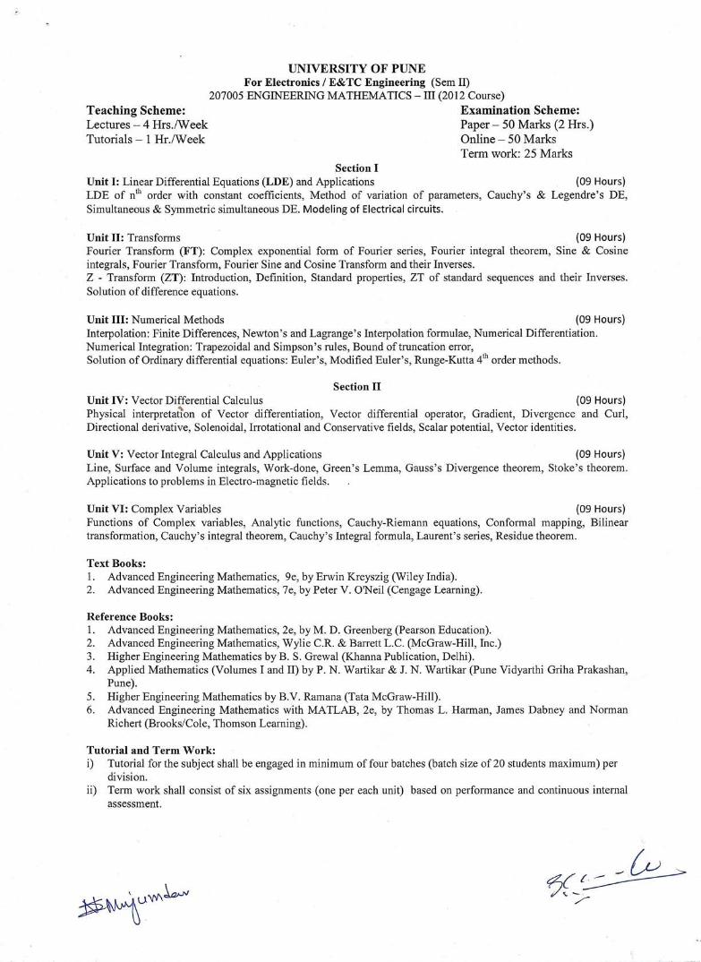
207005 Engineering Maths-III 4 1 - 50 25 - - 50 125
204187 Integrated Circuits 3 - 2 50 - 50 - 50 150
204188 Control Systems 3 1 - 50 25 - - 50 125
204189 Analog Communication 4 - 2 50 - 50 - 50 150
204190 Computer Organization 3 - - 50 - - - 50 100
204191 Object Oriented Programming
2 - 2 - 25 - 50 - 75
204192 Soft Skills 1 - 2 - 25 - - - 25
Total 20 2 8 250 100 100 50 250 750
Dr. D S Bormane Chairman, BOS(Electronics) University of Pune, Pune
3
204181 Signals and Systems
Teaching Scheme:
Lectures: 4 Hrs/ Week
Tutorial : 1 Hr/Week
Examination Scheme:
Theory Online : 50 Marks
Theory Paper : 50 Marks
Term work: 25
Course Objectives and Outcomes:
The concept and theory of signals and systems are needed in almost all electronics and
telecommunication engineering fields and in many other engineering and scientific disciplines as
well. The main objective of this course is to lay the foundation for further studies in areas such
as communication, signal processing, and control systems etc. This course will explore the basic
concepts of signals and systems.
Having successfully completed this course, the student will be able to:
1. Understand the basic signals and their classification, perform operations on signals.
2. Understand and identify the systems based on their properties
3. Understand, identify the system based on their properties in terms impulse response and
also solve the convolution integral and sum.
4. Understand, and resolve the signals in frequency domain using Fourier series and Fourier
transform. Find the amplitude spectrum, phase spectrum of the various signals and also
systems. Analyze the system in frequency domain.
5. Understand, and resolve the signals in complex frequency domain using Laplace
Transform. Analyze the system in s – domain. Characterize the system in s- domain.
Apply Laplace transforms to analyze electrical circuits.
6. Understand, apply and determine the correllogram, auto correlation, cross correlation,
energy spectral density, and power spectral density of discrete and continuous signals.
Carry out the system analysis and inter play between frequency and time domain.
7. Understand the basic concept of probability, random variables and random signals.
Calculate the CDF, PDF and probability of a given event. Calculate the mean, mean
square, variance and standard deviation for given random variables using pdf.

4
Unit I : Introduction to Signals and Systems 10L
Definition of signals and systems, communication and control systems as examples,
Classification of signals: Continuous time and discrete time, even, odd, periodic and non
periodic, deterministic and non deterministic, energy and power.
Operations on signals: Amplitude scaling, addition, multiplication, differentiation, integration
(Accumulator for DT), time scaling, time shifting and folding, precedence rule.
Elementary signals: exponential, sine, step, impulse and its properties, ramp, rectangular,
triangular, signum, sinc.
Systems: Definition, Classification: linear and non linear, time variant and invariant, causal and
non-causal, static and dynamic, stable and unstable, invertible.
Unit II : System Analysis 8L
System modeling: Input output relation, impulse response, block diagram, integro-differential
equation. Definition of impulse response, convolution integral, convolution sum, computation of
convolution integral using graphical method for unit step to unit step, unit step to exponential,
exponential to exponential and unit step to rectangular, rectangular to rectangular only.
Computation of convolution sum. Properties of convolution, system interconnection, system
properties in terms of impulse response, step response in terms of impulse response.
Unit III : System Analysis in Frequency Domain using Fourier Transform 6L
Definition and necessity of CT and DT Fourier series and Fourier transforms. Analogy between
CTFS, DTFS and CTFT, DTFT. CT Fourier series, CT Fourier transform and its properties,
problem solving using properties, amplitude spectrum, phase spectrum of the signal and system.
Interplay between time and frequency domain using sinc and rectangular signals. Limitations of
FT and need of LT and ZT.
Unit IV : System Analysis in Frequency Domain using Laplace Transform 6L
Definition and its properties, ROC and pole zero concept. Application of Laplace transforms to
the LTI system analysis. Inversion using duality, numerical based on properties. Signal analysis
5
using LT.
Unit V : Correlation and Spectral Density 6L
Definition of Correlation and Spectral Density, correllogram, analogy between correlation,
covariance and convolution, conceptual basis, auto-correlation, cross correlation, energy/power
spectral density, properties of correlation and spectral density, inter relation between correlation
and spectral density.
Unit VI : Probability, Random Variables and Random Signals 6L
Experiment, sample space, event, probability, conditional probability and statistical
independence. Random variables: Continuous and Discrete random variables, cumulative
distributive function, Probability density function, properties of CDF and PDF. Statistical
averages, mean, moments and expectations, standard deviation and variance. Probability models:
Uniform, Gaussian, Binomial. Evolution and definition of random signal through probability via
random variable.
Text Books :
1. Simon Haykins and Barry Van Veen, “Signals and Systems”, 2nd Edition, Wiley India.
2. Simon Haykins, “ An Introduction to Analog and Digital Communications”, Wiley India
Reference Books :
1. Mrinal Mandal and Amir Asif, Continuous and Discrete Time Signals and Systems,
Cambridge University Press, 2007
2. Charles Phillips, “Signals , Systems and Transforms” , 3rd Edition, Pearson Education.
3. Peyton Peebles, “Probability, Random Variable, Random Processes”, 4 th Edition, Tata
Mc Graw Hill.
4. Luis F. Chaparro, Signals and Systems using MATLAB, Academic Press an imprint of
Elsevier Inc, 2011
5. M.J.Roberts and Govind Sharma, “Fundamentals of Signals and Systems”,2nd edition,Mc
Graw Hill,2010

6
Signals and Systems
(Tutorial Assignments) Tutorials must be conducted batch wise. Batch size should not be more than 20 students.
The main objective of this tutorial is to focus on the outcomes defined in the theory syllabus by
solving the following assignments based on paper work.
1 A) Sketch and write defining mathematical expression for the following signals in CT and DT
a) Unit Step.
b) Rectangular
c) Exponential
d) Signum
e) Sine
f) Sinc
g) Triangular
h) Unit Impulse.
i) Unit Ramp
B) Classify and find the respective value for the above signals
a) Periodic / Non Periodic
b) Energy / Power /Neither
2 Take any two CT and DT signals and perform the following operation Amplitude scaling,
addition, multiplication, differentiation, integration (accumulator for DT), time scaling,
time shifting and folding
3 Express any two system mathematical expressions in input output relation form and
determine whether each one of them is, Memory less, Causal, Linear, Stable, Time in
variant, Invertible
4 Express any two system mathematical expressions in impulse response form and
determine whether each one of them is, Memory less, Causal, Linear, Stable, Time in
variant, Invertible

7
5 State and prove the properties of CT Fourier Transform. Take rectangular and sinc signal
as examples and demonstrate the applications of CTFT properties. And also demonstrate
the interplay between the time and frequency domain
6 State and prove the properties of CT Laplace Transform. Take any example of a system in
time domain and demonstrate the application of LT in system analysis
7 A) Find the following for the given energy signal
a) Autocorrelation
b) Energy from Autocorrelation
c) Energy from definition
d) Energy Spectral Density directly
e) ESD from Autocorrelation
B) Find the following for the given power signal
a) Autocorrelation
b) Power from Autocorrelation
c) Power from definition
d) Power Spectral Density directly
e) PSD from Autocorrelation
8 A) List and Explain the properties of CDF & PDF, Suppose a certain random variable has the
CDF
10
1000
100
02
xx
x
kkxxFX
Evaluate k, Write the corresponding PDF and find the values of P(X 5) and P 75 X
(This is only an example. Various Probability functions may be given)
B) Find mean ,mean square , standard deviation , variance of X
when xuaexf axX
with a>0
(This is only an example. Various Probability functions may be given)
8
204182 Electronic Devices And Circuits
Teaching Scheme:
Lectures: 4 Hrs/ Week
Practical: 2 Hrs/Week
Examination Scheme:
Theory Online : 50 Marks
Theory Paper : 50 Marks
Practical: 50 Marks
Course Objectives and Outcomes:
The objective of the course is to introduce the students to semiconductor devices (such as BJT,
MOSFET) and their characteristics, analysis, operation, circuits and applications.
Having successfully completed this course, the student will be able to:
1. Understand and apply basic and semiconductor principles to the device to observe its
performance.
2. Comply and verify parameters after exciting devices by any stated method.
3. Simulate electronics circuits using computer simulation software to obtain desired results.
4. Understand and verify simulated circuit with hardware implementation.
5. Implement hardwired circuit to test performance and application for what it is being designed.
6. Analyze and model BJT and MOSFET for small signal.
7. Understand and apply concept of feedback to improve stability of circuits.
8. Understand behavior of transistors at low and high frequency.
Unit I : Bipolar Junction Transistors DC Circuits 6L
The Operating Point, Bias Stability, Self Bias or Emitter Bias, Stabilization against Variations
in ICO, VBE and β, General Remarks on Collector – Current Stability, Bias Compensation
Techniques, Thermal Runaway, Thermal Stability.
Unit II : BJT at Low Frequencies 8L
Two Port Devices and the Hybrid Model, Transistor Hybrid Model, Small Signal Amplifier
Performance in terms of h-parameters, exact analysis of BJT CE, Comparison of CE, CC & CB
Amplifier’s performance parameters, High Input Impedance Transistor Circuits
9
Unit-III Frequency Response of Amplifiers & BJT at High Frequency 8L
Frequency Response of an Amplifier, Step Response of an Amplifier, Bandpass of Cascaded Stages, RC-Coupled Amplifier, Low-Frequency Response of an RC-Coupled Stage, The Hybrid-π Common-Emitter Transistor Model, Hybrid-π Conductances, The Hybrid-π Capacitances, The CE Short-Circuit Current Gain, Current Gain with Resistive Load
Unit IV : Feedback amplifiers and Oscillators 8L
The Feedback Concept, The Transfer gain with Feedback, General Characteristics of Negative-Feedback Amplifiers, Topologies of Negative-Feedback, Summery of Effect of Negative-Feedback on Gain, Input Resistance , Output Resistance & Bandwidth of Amplifier, Sinusoidal Oscillators, The Transistor Phase-Shift Oscillator, A General form of LC Oscillator Circuit, Transistor Hartley & Colpitts Oscillator
Unit V : Large Signal Low Frequency Amplifiers 6L
Power BJTs, Classification of Amplifies, Class A Large-Signal Amplifiers, Second –Harmonic Distortion, The Transformer-Coupled Audio Power Amplifier & it’s Efficiency, Class B Amplifiers, Class B Push-Pull & Complementary-Symmetry Amplifier, Class AB Operation
Unit VI : E-MOSFET’s DC & AC Circuits 8L
Non-ideal voltage current characteristics of EMOSFET. Biasing of EMOSFET Common source circuit, Load Line & Modes of operation, DC Analysis, constant current source biasing. Small Signal Parameters, Small Signal Equivalent Circuit, Analysis of CS amplifier. Introduction to Bi-CMOS Technology. The E-MOSFET internal capacitances and high frequency model.
Text Books :
1. Millman, Halkias, “Integrated Electronics- Analog and Digital Circuits and Systems”, 2nd
TMH.
2. Donald Neamaen, “Electronic Circuit Analysis and Design”, 3rd Edition, TMH.
10
List of Experiments:
Exp no.
Name of experiment Practical
Turns
1 Build and test a sensing circuit for slotted disc using photo diode/ Optocoupler [H 21 A 1] in RPM indicator.
Identify the terminal of optical device. Relevance of slot and speed. Measure RPM using oscilloscope/frequency counter.
1
2 Transistor as a switch to drive LED, relay and single seven segment display (common Anode) use BC547.
Measure IC and VCEsat for each drive. To find critical input current required to operate switch (On/Off). Justification for why CB and CC configuration are not preferred as an
electronic switch.
1
3 Verify DC operating point for a single stage BJT in CE configuration.
Calculate values biasing resistors (R1,R2,RE) to operate BJT at a certain VCEQ & ICQ
Build the circuit with these components Measure VCEQ, ICQ, IBQ and VBEQ Compare measured quantities with theoretical values
2
4 Build and test single stage CE amplifier.
Use the circuit build in Experiment No. 3 Connect coupling and emitter bypass capacitors To measure the voltage gain, input resistance (Ri), output
Resistance (Ro) of the amplifier. Verify phase difference between input and output voltage. To measure the bandwidth using square wave testing.
1
5 Simulate a Single stage BJT amplifier (CE, CB and CC) for given 1
Reference Books :
1. David A.Bell, “Electronic Devices and Circuits”, 5th Edition, Oxford press
2. Boylstad, Nashlesky, “Electronic Devices and Circuits Theory”, 9th Edition, PHI, 2006.
3. Sedra Smith, “Microelectronics Circuits, 5th Edition, Oxford, 1999.

11
specifications.(DC & AC Analysis)
Implement the circuit build in Experiment No. 4 in simulation software.
To measure the voltage gain (AV), input resistance (Ri), output Resistance (RO) of the CE, CB and CC amplifier.
To observe and print input and output waveforms to understand the phase difference in each configuration.
6 Simulate frequency response of single stage CE amplifier (use same circuit)
To study the effect of coupling capacitor and bypass capacitor on low frequency response.
To study effect of external shunting capacitor on high frequency response (To restrict bandwidth).
To understand dominant RC circuit for fL and fH.
1
7 Voltage-Series feedback amplifier
To identify topology of feedback with proper justification. To measure voltage gain, input resistance, output resistance and
bandwidth (using square wave testing) for without feedback. To measure voltage gain, input resistance, output resistance and
bandwidth (using square wave testing) for with feedback. To verify the improvement in various parameters as per the derived
equations.
2
8 Simulation of current shunt feedback amplifier
To identify topology of feedback with proper justification. To measure current gain, input resistance, output resistance and
bandwidth for without feedback. To measure current gain, input resistance, output resistance and
bandwidth for with feedback. To verify the improvement in various parameters as per the derived
equations.
1
9 Simulation of transistorized oscillator
Implement the Phase shift oscillator. Verify Barkhausen criteria. Implement the crystal oscillator (series / parallel resonance circuit). To observe the output voltage waveform. To calculate frequency of oscillation theoretically and practically.
1
10 Build & Test transistorized oscillator 1

12
Implement the LC (Colpitts / Hartley) oscillator. Verify Barkhausen criteria. To observe the output voltage waveform. To calculate frequency of oscillation theoretically and practically.
11 Complementary Symmetry push pull amplifier
To verify DC condition To understand class of operation. To calculate the percentage conversion efficiency. To calculate power dissipation of both transistor. To observe and elimination of crossover distortion.
1
12 MOSFET as a switch (CD4007C)
NMOS switch with Ohmic load.
CMOS inverter.
Realization of NAND using PMOS and NMOS.
1
Note: Conduct Experiment 7 OR 8 and 9 OR 10.
13
204183 Network Theory
Teaching Scheme:
Lectures: 3 Hrs/ Week
Tutorial : 1 Hr/Week
Examination Scheme:
Theory Online : 50 Marks
Theory Paper : 50
Term work: 25
Course Objectives and Outcomes:
The objective of the course is to introduce the student to fundamentals of Network theory including its
concepts, initial and final conditions of components, transient ant steady state response, network
theorems, two-port network, network parameters, resonance and LC filters. With this the students
will have the knowledge of how to evaluate and analyze any complex network.
Having successfully completed this course, the student will be able to:
1. Understand, Analyze the basic AC and DC circuits using KCL,KVL and network Theorems
2. Determine the voltages, currents, power and impedances at various nodes and loops using all
the simplification techniques.
3. Understand and apply graph theory to solve network equations
4. Understand, and calculate the initial conditions of RL, RC circuits
5. Formulate, solve the differential equations for RL, RC, and RLC circuits and carry out the
transient analysis.
6. Understand, identify and analyze the series, parallel resonance circuits, calculate the
bandwidth, selectivity, Q-factor also.
7. Understand, analyze and design prototype LC filters and Resistive attenuators.
8. Characterize; model the network in terms of all network parameters and analyze.
8. Understand and formulate the network transfer function in s-domain and pole, zero concept.
Unit I : Basic Circuit Analysis and Simplification Techniques 8L
Kirchoff’s Current and Voltage Laws, Independent and dependent sources and their interconnection,
and power calculations.
Network Analysis: Mesh, Super mesh, Node and Super Node analysis. Source transformation and
source shifting.
Network Theorems: Superposition, Thevenin’s, Norton’s and Maximum Power Transfer Theorems,
14
Millers Theorem and its dual.(AC circuit analysis for all the topics of this unit)
Unit II : Graph Theory and Network Equations 5L
Network graph, tree, co-tree, and loops. Incidence matrix, tie-set, cut-set matrix. Formulation of
equilibrium equations in matrix form, solution of resistive networks and principle of duality
Unit III : Transient Analysis of Basic RC, RL and RLC Circuits 6L
Initial conditions, source free RL and RC circuits, properties of exponential response, Driven RL and
RC circuits, Natural and Forced response of RL and RC circuits. Introduction to Source free and
driven series RLC circuit. Over damped and Under damped series RLC circuit.
Unit IV : Frequency Selective Networks 6L
Significance of Quality factor.
Series Resonance: Impedance, Phase angle variations with frequency, Voltage and current variation
with frequency, Bandwidth, Selectivity. Effect of Rg on BW & Selectivity. Magnification factor.
Parallel resonance: Resonant frequency and admittance variation with frequency, Bandwidth and
selectivity. General case: Resistance present in both branches.
Comparison and applications of series and parallel resonant circuits.
Unit V : Filters and Attenuators 6L
Classifications: Symmetrical and Asymmetrical networks.
Properties of two port Network: Symmetrical Networks (T and only). Z0 and γ in terms of circuit
components.
Asymmetrical Networks: Image Impedance and Iterative Impedance (L-Section only).
Filters: Filter fundamentals, Constant K-LPF, HPF, BPF and BSF, introduction to concept of m-
derived LPF and HPF, Terminating half sections, and composite filters. (Derivation and design of m-
derived filters is not expected).
Attenuators: Introduction to Neper and Decibel. Symmetrical T and type attenuators.

15
Unit VI : Two Port Network Parameters and Functions 6L
Terminal characteristics of network: Z, Y, h, ABCD Parameters; Reciprocity and Symmetry
conditions, Applications of the parameters. Application of Laplace Transforms to circuit analysis.
Network functions for one port and two port networks, Pole-zeros of network functions and network
stability.
Text Books :
1. William H Hayt, Jack E Kimmerly and Steven M.Durbin, Engineering Circuit Analysis, Tata
McGraw Hill
2. D Roy Choudhury, Networks and Systems, New Age International Publishers
Reference Books :
1. John D. Ryder, Network Lines and Fields by, PHI
2. M. E. Van Valkenburg, Network Analysis, PHI / Pearson Education, 3rd Edition. Reprint 2002
3. Franklin F. Kuo, Network analysis and Synthesis, , Wiley International Edition
4. B.Somanahan Nair and S.R.Deepa, “ Network analysis and Synthesis “ Elsevier ,2012
16
Network Theory
(Tutorial Assignments) Tutorials must be conducted batch wise. Batch size should not be more than 20 students.
The main objective of this tutorial is to focus on the outcomes defined in the theory syllabus by
solving the following assignment based on paper work.
1 Determine the following using KCL,KVL, node, loop analysis and circuit simplification
techniques
1. Currents through various given branches
2. Voltages across the given branches
3. Power absorbed or delivered by a given component
(Various network involving resistors, inductors, capacitors, dependent and independent
current and voltages sources may be given and students are expected to analyze the
network and determine the above. Analysis of AC, and DC both is expected)
2 Determine the following using Network Theorems. One problem statement on each
theorem.
1. Currents through various given branches
2. Voltages across the given branches
3. Power absorbed or delivered by a given component
(Various network involving resistors, inductors, capacitors, dependent and independent
current and voltages sources may be given and students are expected to analyze the
network and determine the above. Analysis of AC, and DC both is expected)
3 Carry out the following analysis of a given network.
1. Draw relevant network graph, tree, co-tree, and loops.
2. Formulate incidence matrix, tie-set, cut-set matrix whichever is applicable.
3. Formulate equilibrium equations in matrix form, and solve.
4. Find the duality.
(One problem on each technique is expected)
17
4 1. Formulate differential equation for RL and RC circuits and solve for current and
voltages by determining initial conditions for driven and source free conditions.
2. Carry out the transient analysis and determine the voltage, current expressions for
a given network involving RL, RC, RLC
(One problem statement on each combination, source free and driven RL, RC,
series RLC network)
5 A. Analyze the series and parallel resonant circuits and derive the equations of Q-
factor, resonance frequency, bandwidth, impedance, and selectivity.
B. Determine Q-factor, resonance frequency, bandwidth, impedance, and selectivity
for a given problem. (One problem on series and parallel resonant circuit each)
6 A. Analyze the LC low pass, high pass, band pass and band stop by deriving cut off
frequency, impedance, and draw the frequency response in terms of impedance
curves.
B. Design prototype constant K – Low, High, Band pass, band stop filters for given
specification. (One problem on each type of filter)
7 Formulate the z, y, h, ABCD parameters and find the conditions for Reciprocity and
Symmetry conditions.
8 Determine the z, y, h, ABCD parameters for a given network
9 Analyze the given network using Laplace Transform and find the network transfer
function
18
204184 Data Structures & Algorithms
Teaching Scheme:
Lectures: 4 Hrs/ Week
Practical : 2 Hrs/Week
Examination Scheme:
Theory Online : 50 Marks
Theory Paper : 50 Marks
Oral: 50 Marks
Course Objectives & Outcomes:
This course provides an introduction to the theory, practice and methods of data structures and
algorithm design. Students will learn elementary data structures such as stacks, queues, linked lists,
trees and graphs in C language, and the algorithms designed for manipulating these data structures. The
objective of this course is to introduce students to both data structures and algorithm design.
Having successfully completed this course, the student will be able to:
a. Choose the data structures that effectively model the information in a problem.
b. Judge efficiency trade-offs among alternative data structure implementations or combinations.
c. Apply algorithm analysis techniques to evaluate the performance of an algorithm and to
compare data structures.
d. Implement and know when to apply standard algorithms for searching and sorting.
e. Design, implement, test, and debug programs using a variety of data structures including lists,
stacks, queues, hash tables, binary tree structures, search trees, heaps, graphs.
Unit I: Introduction to Algorithm & Program Design 8L
Basic Terminology; Elementary data organization, Data Structures, Data structure operations, Abstract
Data Type.
Algorithm: Complexity, Time Space Tradeoff, Algorithmic Notations, Control Structures, Complexity
of Algorithms, Sub-algorithms, Functions in C: Passing by value, recursive functions, Local & Global
Variables, Arrays: Arrays in C and various operations. Searching Algorithms: Algorithms for
Sequential Search, Indexed Sequential Search, Binary Search.

19
Unit II: Arrays, records and Pointers 8L
Sorting Algorithms: Selection sort, Bubble sort, Insertion Sort.
Multidimensional Arrays, Representation of polynomials using arrays.
Strings: Basic Terminology, Strings as ADT, and string operations.
Pointers: Basic concepts, Pointer declaration & initialization, Pointer to a pointer, Functions &
Pointers, Array of pointers, Arrays & Pointers: Dynamic memory management.
Records: Structures in C, Comparison with arrays as a data structure. Array of structures, Pointers and
structures, Polynomial representation using array of structures, Unions, Bitwise operators.
Unit III: Linked Lists 7L
Singly Linked Lists: Concept, Linked List as ADT, Representation of Linked list in Memory,
Traversing a linked list, Searching a linked list, Memory Allocation; Garbage collection, Insertion into
Linked list, Deletion from a linked list, Header Linked List, Representation of polynomial, Circularly
Linked list, Doubly Linked List.
Unit IV: Stacks, Queues, Recursion 7L
Stacks: Concept, Array representation of stacks, Linked representation of stacks, Stack as ADT,
Arithmetic expressions; Polish notation. Application of stacks: Recursion, Implementation of
recursive procedures by stacks.
Queues: Concept, Array representation of queues, Linked representation of queues, Queue as ADT,
Circular queues, Dequeues, Priority queues. Application of queues: Categorizing data, Simulation of
queues.
Unit V: Trees 7L
Binary Trees: Concept & Terminologies, Representation of Binary Tree in memory, Traversing a
binary tree, Traversal algorithms using stacks, Header Nodes; Threads, Binary Search Trees (BST),
Searching and inserting in BST, Deleting in a BST, Balanced Binary Trees.
Application of Trees: Expression Tree, Game Trees.
Unit VI: Graphs 7L
Graphs: Graph theory terminology, Sequential representation of graphs; Adjacency matrix, Path
matrix, Linked representation of a graph, Operations on graph, Traversing a graph, Topological
sorting, Spanning trees; Minimum Spanning tree, Kruskal’s Algorithm, Prim’s Algorithm.
20
Text Books:
1. Seymour Lipschutz, Data Structure with C, Schaum’s Outlines, Tata McGrawHill
2. Yashavant Kanetkar, Data Structures Through C, BPB Publication, 2nd Edition
Reference books:
1. E Balgurusamy - Programming in ANSI C, Tata McGraw-Hill (Third Edition)
2. Yedidyah Langsam, Moshe J Augenstein, Aaron M Tenenbaum – Data structures using C and
C++ - PHI Publications ( 2nd Edition ).
3. Ellis Horowitz, Sartaj Sahni- Fundamentals of Data Structures – Galgotia Books source.
4. Data Structures using C , ISRD Group, Mc Graw Hill
List of Practical:
Write Programs in C to implement
1. Searching methods-Linear & Binary
2. Sorting Methods-Bubble, Selection & Insertion.
3. Data base Management using array of structure with operations Create, display, Modify,
Append, Search and sort.
4. Polynomial addition using array of structure.
5. Singly linked list with operations Create, Insert, Delete, Search.
6. Stack using arrays & Linked Lists.
7. Queue using array & Linked Lists.
8. Evaluation of postfix expression (input will be postfix expression)
9. Binary search tree: Create, search, recursive traversals.
10. Graph using adjacency Matrix with BFS & DFS traversals.

21
204185 Digital Electronics
Teaching Scheme:
Lectures: 4 Hrs/ Week
Practical : 2 Hrs/week
Examination Scheme:
Theory Online : 50 Marks
Theory Paper : 50Marks
Practical: 50 Marks
Course Objectives and Outcomes:
The concept and theory of digital Electronics are needed in almost all electronics and
telecommunication engineering fields and in many other engineering and scientific disciplines as well.
The main objective of this course is to lay the foundation for further studies in areas such as
communication, VLSI, computer, microprocessor etc. One of the most important reasons for the
unprecedented growth of digital electronics is the advent of integrated circuit. This course will explore
the basic concepts of digital electronics.
Having successfully completed this course, the student will be able to:
1. Understand the basic logic gates and various variable reduction techniques of digital logic
circuit in detail.
2. Understand, identify and design combinational and sequential circuits
3. Design and implement hardware circuit to test performance and application for what it is being
designed.
4. Simulate and verify using computer simulation software to obtain desired result.
5. Understand and verify simulated circuit model with hardware implementation.
Unit I: Digital Logic Families 8L
Classification of logic families, Characteristics of digital ICs-Speed of operation, power dissipation,
figure of merit, fan in, fan out, current and voltage parameters, noise immunity, operating temperatures
and power supply requirements.TTL logic. Operation of TTL NAND gate, active pull up, wired AND,
open collector output, unconnected inputs. Tri-State logic. CMOS logic – CMOS inverter, NAND,
NOR gates, unconnected inputs, wired logic , open drain output. Interfacing CMOS and TTL.
Comparison table of Characteristics of TTL, CMOS, ECL, RTL, I2L, DCTL.
22
Unit II : Combinational Logic Design 8L
Standard representations for logic functions, k map representation of logic functions (SOP m POS
forms), minimization of logical functions for min-terms and max-terms (upto 4 variables), don’t care
conditions, Design Examples: Arithmetic Circuits, BCD - to – 7 segment decoder, Code converters.
Adders and their use as subtractions, look ahead carry, ALU, Digital Comparator, Parity
generators/checkers, Multiplexers and their use in combinational logic designs, multiplexer trees,
Demultiplexers and their use in combinational logic designs, Decoders, demultiplexer trees.
Introduction to Quine McCluskey method.
Unit III : Sequential Logic Design 8L
1 Bit Memory Cell, Clocked SR, JK, MS J-K flip flop, D and T flip-flops. Use of preset and clear
terminals, Excitation Table for flip flops. Conversion of flip flops. Application of Flip flops: Registers,
Shift registers, Counters (ring counters, twisted ring counters), Sequence Generators, ripple counters,
up/down counters, synchronous counters, lock out, Clock Skew, Clock jitter. Effect on synchronous
designs.
Unit IV : State Machines 8L
Basic design steps- State diagram, State table, State reduction, State assignment, Mealy and Moore
machines representation, Implementation, finite state machine implementation, Sequence detector.
Unit V : Programmable Logic Devices and Semiconductor Memories- 6L
Programmable logic devices: Detail architecture, Study of PROM, PAL, PLA, Designing
combinational circuits using PLDs. General Architecture of FPGA and CPLD
Semiconductor memories: memory organization and operation, expanding memory size, Classification
and characteristics of memories, RAM, ROM, EPROM, EEPROM, NVRAM, SRAM,DRAM,
Unit VI : Introduction to HDLs 7L
Library, Entity, Architecture, Modeling styles, Data objects, Concurrent and sequential statements,
Design examples, using VHDL for basic combinational and sequential circuits, Attributes (required for
23
List of Experiments
All the following Practicals are mandatory.
1 Verify four voltage and current parameters for TTL and CMOS (IC 74LSXX, 74HCXX),
(Refer Data-Sheet).
2 Study of IC-74LS153 as a Multiplexer. (Refer Data-Sheet).
Design and Implement 8:1 MUX using IC-74LS153 & Verify its Truth Table.
Design & Implement the given 4 variable function using IC74LS153. Verify its Truth-
Table.
3 Study of IC-74LS138 as a Demultiplexer/ Decoder (Refer Data-Sheet).
practical) (Test benches and FSM excluded).
Text Books :
1. R.P. Jain , “Modern digital electronics” , 3rd edition , 12threprint TMH Publication, 2007.
2. Stephen Brown, “Fundamentals of digital logic design with VHDL” 1stedition, TMH
Publication 2002
Reference Books :
1. A. Anand Kumar, “Fundamentals of digital circuits” 1stedition, PHI publication, 2001
2. Wakerly Pearon, “Digital Design: Principles and Practices”, 3rdedition, 4threprint, Pearon
Education, 2004
3. J. Bhaskar, “VHDL Primer” 3rd Edition.PHI Publication.
4. Mark Bach, “Complete Digital Design”, Tata MCGraw Hill, 2005.
5. Volnei Pedroni, “ Digital: Electronics and Design with VHDL”, Elsevier
24
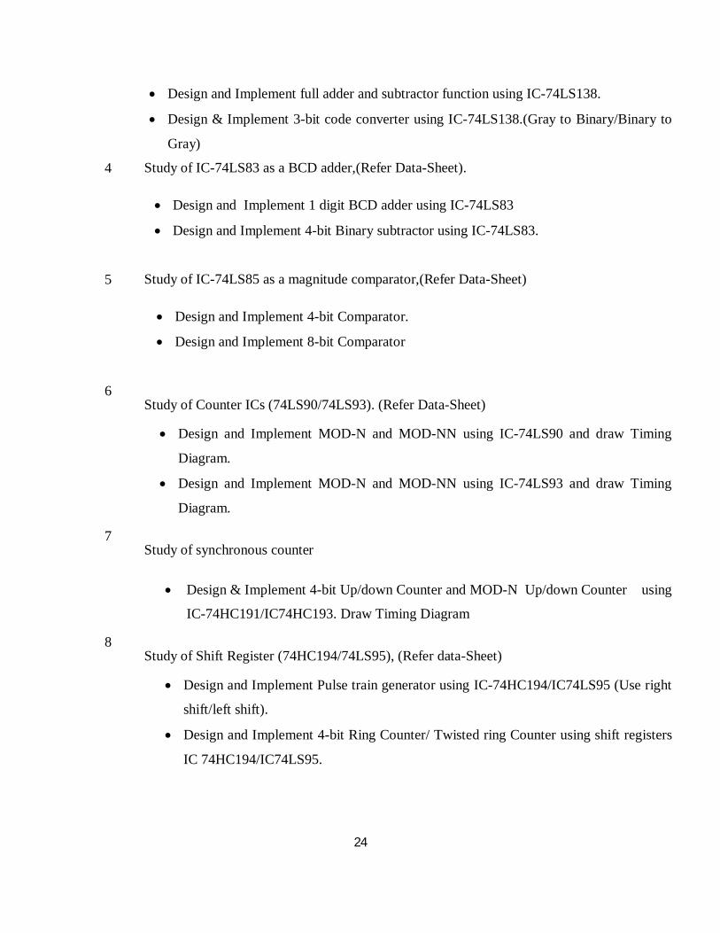
Design and Implement full adder and subtractor function using IC-74LS138.
Design & Implement 3-bit code converter using IC-74LS138.(Gray to Binary/Binary to
Gray)
4 Study of IC-74LS83 as a BCD adder,(Refer Data-Sheet).
Design and Implement 1 digit BCD adder using IC-74LS83
Design and Implement 4-bit Binary subtractor using IC-74LS83.
5 Study of IC-74LS85 as a magnitude comparator,(Refer Data-Sheet)
Design and Implement 4-bit Comparator.
Design and Implement 8-bit Comparator
6 Study of Counter ICs (74LS90/74LS93). (Refer Data-Sheet)
Design and Implement MOD-N and MOD-NN using IC-74LS90 and draw Timing
Diagram.
Design and Implement MOD-N and MOD-NN using IC-74LS93 and draw Timing
Diagram.
7 Study of synchronous counter
Design & Implement 4-bit Up/down Counter and MOD-N Up/down Counter using
IC-74HC191/IC74HC193. Draw Timing Diagram
8 Study of Shift Register (74HC194/74LS95), (Refer data-Sheet)
Design and Implement Pulse train generator using IC-74HC194/IC74LS95 (Use right
shift/left shift).
Design and Implement 4-bit Ring Counter/ Twisted ring Counter using shift registers
IC 74HC194/IC74LS95.

25
9
Write, simulate and verify, VHDL Code for four bit logical and arithmetic operations for
ALU.
Behavioral modeling
Dataflow modeling
10 D FF and JK FF (With Synchronous and asynchronous reset input)
(Use Behavioral modeling)
Write, simulate and verify, VHDL Code for D flip flop using Synchronous
/asynchronous reset input
Write, simulate and verify, VHDL Code for JK flip flop using asynchronous set
/reset Input
11 Four bit ripple counter. (Use data flow/Structural modeling)
Write, simulate and verify, VHDL code for four bit ripple up counter
Write, simulate and verify VHDL code for four bit ripple up/down Counter using
mode control.

26
204186 Electronic Measuring Instruments and Tools
Teaching Scheme:
Lectures: 1 Hr/ Week
Practical: 2 Hrs/Week
Examination Scheme:
Term work : 50 Marks
Course Objectives and Outcomes:
Many advanced electronic measuring instruments are being innovated and introduced in the market. It
is essential for an electronics engineer to know the functions, specifications and make the
measurements on many of the instruments. The main objective of this course is to introduce and
expose the students to various measuring instrument, their block diagram, specifications and
applications.
Having successfully completed this course, the student will be able to:
1. Understand fundamental of measurements of various electrical parameters.
2. Aware and identify the control panels of measuring and generating instruments.
3. Understand and describe specifications, features and capabilities of electronic instruments.
4. Select appropriate instrument for the measurement of electrical parameter professionally.
5. Finalize the specifications of instrument and select an appropriate instrument for given
measurement.
6. Make the required measurement using various instruments.
Following list of experiments is broad based on block diagram, specifications, features, various
measurement capabilities and applications of various essential instruments that are being used in E &
T/C engineering professionally. It is expected that teaching faculty will explore these instruments in
detail in respective laboratory sessions. Prominent specifications of the instrument should be listed and
attached in file/journal.
List of Practicals (Any Ten)
1. Carry out Statistical Analysis of Digital Voltmeter
Calculate mean, standard deviation, average deviation, and variance.
Calculate probable error.
27
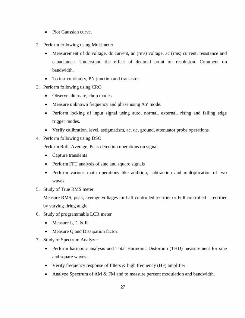
Plot Gaussian curve.
2. Perform following using Multimeter
Measurement of dc voltage, dc current, ac (rms) voltage, ac (rms) current, resistance and
capacitance. Understand the effect of decimal point on resolution. Comment on
bandwidth.
To test continuity, PN junction and transistor.
3. Perform following using CRO
Observe alternate, chop modes.
Measure unknown frequency and phase using XY mode.
Perform locking of input signal using auto, normal, external, rising and falling edge
trigger modes.
Verify calibration, level, astigmatism, ac, dc, ground, attenuator probe operations.
4. Perform following using DSO
Perform Roll, Average, Peak detection operations on signal
Capture transients
Perform FFT analysis of sine and square signals
Perform various math operations like addition, subtraction and multiplication of two
waves.
5. Study of True RMS meter
Measure RMS, peak, average voltages for half controlled rectifier or Full controlled rectifier
by varying firing angle.
6. Study of programmable LCR meter
Measure L, C & R
Measure Q and Dissipation factor.
7. Study of Spectrum Analyzer
Perform harmonic analysis and Total Harmonic Distortion (THD) measurement for sine
and square waves.
Verify frequency response of filters & high frequency (HF) amplifier.
Analyze Spectrum of AM & FM and to measure percent modulation and bandwidth.

28
8. Study of Frequency Counter
Carry out measurements through different modes of measurement.
Measure frequency, time, ratio, events & pulse width.
9. Calibration of Digital Voltmeter (DVM)
Calibrate DVM for dc voltage, ac voltage and dc current.
10. Study function generator/Arbitrary waveform generator
Generate signal of required amplitude, frequency, duty cycle, offset etc.
Generate special signals such as noise, ECG, sweep, burst, AM, FM, PM etc.
31
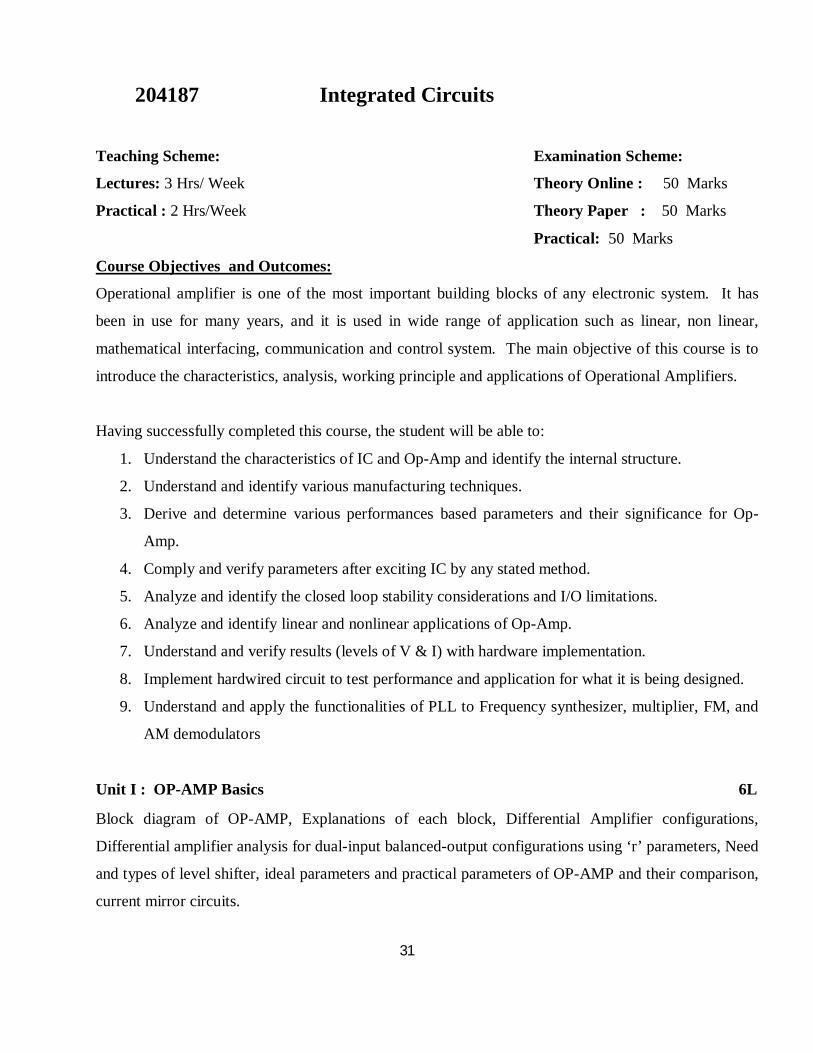
204187 Integrated Circuits
Teaching Scheme:
Lectures: 3 Hrs/ Week
Practical : 2 Hrs/Week
Examination Scheme:
Theory Online : 50 Marks
Theory Paper : 50 Marks
Practical: 50 Marks
Course Objectives and Outcomes:
Operational amplifier is one of the most important building blocks of any electronic system. It has
been in use for many years, and it is used in wide range of application such as linear, non linear,
mathematical interfacing, communication and control system. The main objective of this course is to
introduce the characteristics, analysis, working principle and applications of Operational Amplifiers.
Having successfully completed this course, the student will be able to:
1. Understand the characteristics of IC and Op-Amp and identify the internal structure.
2. Understand and identify various manufacturing techniques.
3. Derive and determine various performances based parameters and their significance for Op-
Amp.
4. Comply and verify parameters after exciting IC by any stated method.
5. Analyze and identify the closed loop stability considerations and I/O limitations.
6. Analyze and identify linear and nonlinear applications of Op-Amp.
7. Understand and verify results (levels of V & I) with hardware implementation.
8. Implement hardwired circuit to test performance and application for what it is being designed.
9. Understand and apply the functionalities of PLL to Frequency synthesizer, multiplier, FM, and
AM demodulators
Unit I : OP-AMP Basics 6L
Block diagram of OP-AMP, Explanations of each block, Differential Amplifier configurations,
Differential amplifier analysis for dual-input balanced-output configurations using ‘r’ parameters, Need
and types of level shifter, ideal parameters and practical parameters of OP-AMP and their comparison,
current mirror circuits.
32
Unit II : OP-AMP IC Technology 6L
Different manufacturing technology, features of each technology, types, symbol and ideal equivalent
circuit of OP-AMP, frequency response, transient response, stability of OP-AMP, frequency
compensation, Effect of temperature on parameters, Noise, Noise model of OP-AMP.
Unit III : Linear Applications of OP-AMP 6L
Inverting and Non-inverting amplifier, voltage follower, voltage scaling, difference amplifier, Ideal
integrator, errors in ideal integrator, practical integrator, frequency response of practical integrator,
applications of integrator, Ideal differentiator, errors in ideal differentiator, practical differentiator,
frequency response of practical differentiator, applications of differentiator, Requirements of
Instrumentation amplifier, 3 OP-AMP Instrumentation amplifier, Instrumentation amplifier
applications.
Unit IV : Non-linear Applications of OP-AMP 6L
Comparator, characteristics of comparator, applications of comparator, Schmitt trigger
(symmetrical/asymmetrical), Square wave generator, triangular wave generator, Problems in basic
rectifier, Need of precision rectifier, Half wave , Full wave precision rectifiers, peak detectors, sample
and hold circuits.
Unit V : Converters using OP-AMP 6L
V-F and F-V converter, I-V and V-I converter, Current amplifier, DAC, types of DAC, characteristics,
specifications, advantages and disadvantages of each type of DAC, ADC, types of ADC,
characteristics, specifications, advantages and disadvantages of each type of ADC.
Unit VI : Special Purpose ICs 6L
PLL types block diagram of PLL, function and types of each block, characteristics/parameters of PLL,
and different applications of PLL.
Voltage Regulator: Block diagram of adjustable three terminal positive and negative regulators
(317,337). Typical connection diagram, current boosting. Low drop out voltage regulators.
33
List of Experiments:
1 Measure op-amp parameters and compare with the specifications.
Measure input bias current, input offset current and input offset voltage.
Measure slew rate (LM/UA741C and LF356)
Measure CMRR
Compare the result with datasheet of corresponding Op Amp.
2 Design, build and test integrator (LF356).
Design Integrator for given fa.
Verify practical and theoretical frequencies fa and fb.
Observe output waveform at fa and fb for Sine and Square wave input.
Plot frequency response for integrator. 3 Design, build and test differentiator (LF356).
Design differentiator for given fa.
Verify practical and theoretical frequencies fa and fb.
Observe output waveform at fa and fb for Sine and Square wave input.
Text Books :
1. Ramakant A. Gaikwad, “Op Amps and Linear Integrated Circuits”, Pearson Education
2. Salivahanan and Kanchanabhaskaran, “Linear Integrated Circuits”, TMH
Reference Books :
1. George Clayton and Steve Winder, “Operational Amplifiers”, Newnes
2. Sergio Franco, “Design with Operational Amplifiers and Analog Integrated Circuits”, TMH
3. Bali,”Linear Integrated Circuits”, Mc Graw Hill
4. Gray, Hurst, Lewise, Meyer, “Analysis & Design of Analog Integrated Circuits, Wiley
Publications.
34
Plot frequency response for differentiator. 4 Design, build and test three Op-amp instrumentation amplifier for typical application
(Ex: temperature measurement)
Implement Wheatstone bridge and balance for null condition.
Calibrate bridge for 0ºC and room temperature.
Set gain of IA amplifier to calibrate circuit for variation in temperature.
Note: Any similar application using IA.
5 Design, build and test precision half & full wave rectifier.
To understand the concept of super diode.
To implement inverting and non-inverting half wave rectifier.
To implement inverting and non-inverting full wave rectifier.
Plot input and output waveforms.
6 Design, build and test Comparator and Schmitt trigger.
Design of Schmitt trigger circuit for given specifications.
Implementations of Schmitt trigger using Op-Amp (LF356).
Without external reference voltage.
With external reference voltage source.
With clamped output.( using Zener diodes; without external reference voltage)
Verification of effect of Vref on output waveforms and hysteresis.
Observe voltage waveforms and hysteresis.
Calculate UTP, LTP and hysteresis theoretically and practically.
7 Design, build and test Sample and hold circuit
Design sample and hold circuit for given specifications.
Implementation S &H using Op-amp(Any one 741,356 or LF 398)
Plot original signal, S&H signal, and Capacitor droop.
Observe the effect of increase in input frequency on sampled output.
8 Design, build and test PLL and any one application.
Study PLL IC 565.
35
Find the free running frequency.
Find lock range and capture range.
9 2 bit DAC and 2 bit ADC.
A) Design and implement 2bit R-2R ladder DAC.
Measure and verify output voltage practically and theoretically.
Calculate resolution, step size and few more specification.
B) Design and implement 2bit flash type ADC.
Verify operation of comparators and priority encoder individually.
Calculate no.of comparator, resolution, full scale voltage range etc.
10 Design, build and test square & triangular wave generator.
Design of Square wave generator for given specifications.
Implementation of circuit using Op-Amp for different duty cycles (LF356).
Verification of effect of slew rate on output waveforms.
Observe voltage waveforms of output and timing capacitor.
Calculate frequency of output waveform theoretically and practically.
Optional Experiments
1 Verify and understand practically virtual ground and virtual short concept in inverting
and non inverting configuration.
2 Design and implement Wien bridge oscillator using Op-Amp.
3 Plot DC transfer characteristics of emitter coupled differential amplifier.
4 Study effect of emitter resistance and constant current source on figure of merit (CMRR)
of emitter coupled differential amplifier.
5 Design and implement V-I converter.
6 Any experiment based on application of Op-Amp
Note:
First 10 experiments are compulsory. Any additional experiment from optional list.
36
204188 Control Systems
Teaching Scheme:
Lectures: 3 Hrs/ Week
Tutorial : 1 Hr/Week
Examination Scheme:
Theory Online : 50 Marks
Theory Paper : 50 Marks
Term work: 25 Marks
Course Objectives and Outcomes:
The concept and theory of control systems are needed in almost all electronics and telecommunication
engineering fields and in many other engineering and scientific disciplines as well. The main
objective of this course is to introduce and give an exposure to the students the fundamentals of
control systems, various components in the control system, time domain, frequency domain analysis
and also the system stability analysis. This course would also provide the basis for control system
analysis using state space analysis and finally the digital control systems and their applications.
Having successfully completed this course, the student will be able to:
1. Model a physical system and express its internal dynamics and input-output relationships by
means of block diagrams, mathematical model and transfer functions.
2. Understand and explain the relationships between the parameters of a control system and its
stability, accuracy, transient behavior.
3. Identify the parameters that the system is sensitive to. Determine the stability of a system and
parameter ranges for a desired degree of stability.
4. Plot the Bode, Nyquist, Root Locus diagrams for a given control system and identify the
parameters and carry out the stability analysis.
5. Determine the frequency response of a control system and use it to evaluate or adjust the
relative stability,
6. Design a P, PD, PI, or PID controller based on the transient and steady state response criteria.
7. Model and analyze the control systems using state space analysis.
37
Unit I : Basics of Control Systems 6L
Introduction , Types of Control Systems : Open loop & Closed loop , Feed back Control System,
Effect of Feed Back , Modeling of Simple Electrical & Mechanical Systems Using Differential
Equations, Concept of Transfer Function , Characteristics Equation, Poles and Zeros , Block Diagram
Algebra ,Control system Components : A.C. & D.C. Servomotors , Stepper Motor
Unit II : Time Domain Analysis 6L
Type and Order of the Control Systems , Types of Standard Inputs , Response of First Order System to
Step, Ramp and Parabolic Inputs , Response of Second Order System to Step Input ,
Time Domain Specifications of Second Order Systems, Steady State Error and Error Coefficients,
Effects of addition of Poles and Zeros
Unit III : Stability 6L
Concept of Stability , Absolute ,Relative , Marginal and Unstable Stability analysis in S Plane ,
Dominant Poles and Zeros , Routh-Hurwitz Criterion , Concept of Root Locus
Unit IV : Frequency Domain Analysis 6L
Need of Frequency Domain Analysis , Correlation between Time & Frequency Domain , Frequency
Domain Specifications , Bandwidth , Bode Plot , Construction of Bode Plot , Gain and Phase Margin ,
Determination of Relative Stability , Nyquist Stability Criterion, Relative Stability Using Nyquist
Criterion
Unit V : State Space Analysis 6L
Advantages of State Space Analysis over Classical Control , Concept of State , State Variables and
State Model , State Space Representation using State Model, State Transition Matrix and its
properties, Solution of State Equations for LTI System , Concept of Controllability and Observability
38
Unit VI : Digital Control Systems 6L
Introduction, Advantages over analog control system, Sampled Data Control System, Transfer
Function of Digital Control System, Step Response (First & Second Order Systems only), Introduction
to Digital PID Controller, Introduction to PLC: Block schematic, PLC addressing, any one application
of PLC using Ladder diagram. Concept of Offset ,P, PI , PD and PID Characteristics
Text Books :
1. Katsuhiko Ogata, Modern Control Engineering, Fifth Edition, PHI Learning Private Limited,
New Delhi, 2010
2. I.J. Nagrath , M.Gopal, Control Systems Engineering, Fifth Edition, New Age International
Publishers, New Delhi, 2007
Reference Books :
1. Curtis D Johnson, Process Control Instrumentation Technology, Eighth Edition, PHI Private
Limited, New Delhi, 2011
2. Richard C. Drof , Robert N. Bishop, Modern Control Systems, Addison Wesley Publishing
Company, 2001
3. B.C.Kuo, Digital Control Systems, Second Edition, Oxford University Press, New York, 1992
39
Control Systems
(Tutorial Assignments) Tutorials must be conducted batch wise. Batch size should not be more than 20 students.
The main objective of this tutorial is to focus on the outcomes defined in the theory syllabus by
solving the following assignment based on paper work. Paper work is compulsory for all assignments;
however it is desirable, few assignments may also be implemented using appropriate software.
Assignment to be given on the following topics.
1. Find overall transfer function of the system using block diagram algebra.
2. Find determine the stability of a system using Routh Hurwitz Criterion, marginal value of K
and frequency of sustained oscillations.
3. Construct the root locus and comment on the stability.
4. Find the time domain specifications of the given system.
5. Find the steady state error and error coefficients of the type 0, 1 and 2 systems for step, ramp
and parabolic inputs.
6. Find frequency domain specifications of the system.
7. Draw Bode Plot, find PM and GM and Comment on the stability. Also, find transfer function
of the system from given Bode plot.
8. Find stability of the system using Nyquist Criteria.
9. Write State space model of the system and solution.
10. Find State Transition Matrix for given system and verify the properties of the same.
11. Find the Transfer Function of a Digital System.
12. Find the response of first and second order Digital Systems for Step Input.
13. Study the Digital PID Controller with reference to response time, steady state error and offset.

40
204189 Analog Communication
Teaching Scheme:
Lectures: 4 Hrs/ Week
Practical: 2 Hrs/ Week
Examination Scheme:
Theory Online : 50 Marks
Theory Paper : 50 Marks
Practical: 50 Marks
Course objectives and Outcomes:
The basic objective of this is course is to introduce the students to analog communication, AM, FM
modulation techniques, their analysis, bandwidth calculations, receivers. It also focuses on the
performance analysis of analog communications systems under the presence of noise and finally
introduces the pulse and digital modulation techniques.
Having successfully completed this course, the student will be able to:
3. Understand and identify the fundamental concepts and various components of analog
communication systems.
4. Understand, analyze and explain various analog modulation schemes.
5. Understand the performance of analog communications systems under the presence of noise.
6. Understand and apply concepts and techniques from Fourier analysis and circuit analysis to
communication systems.
7. Develop the ability to compare and contrast the strengths and weaknesses of various
communication systems
8. Analyze Basic communications systems and their performance under the presence of noise
9. Describe various pulse and digital modulation techniques.
Unit I : Amplitude (Linear) Modulation 8L
Base band & Carrier communication, Generation of AM (DSBFC) and its spectrum, Power relations
applied to sinusoidal signals, DSBSC – multiplier modulator, Non linear generation, switching
modulator, Ring modulator & its spectrum, Modulation Index. SSBSC, ISB & VSB, their generation
methods & Comparison, AM Broadcast technical standards (Only Analytical treatment)
41
Unit II : Angle(Exponential) Modulation 8L
Instantaneous frequency, Concept of Angle modulation, frequency spectrum, Narrow band & wide band
FM, Modulation index, Bandwidth, Phase Modulation, Bessel’s Function and its mathematical analysis,
Generation of FM (Direct & Indirect Method), Comparison of FM and PM.
Unit III : AM and FM Receivers 8L
Block diagram of AM and FM Receivers, Super heterodyne Receiver, Performance Characteristics:
Sensitivity, Selectivity, Fidelity, Image Frequency Rejection and IFRR. Tracking, Mixers. AM
Detection: Rectifier detection, Envelope detection; Demodulation of DSBSC: Synchronous detection;
Demodulation of SSBSC: Envelope detection; FM Detection using PLL.
Unit IV : Noise 6L
Sources of Noise, Types of Noise, White Noise, Thermal noise, shot noise, partition noise, Low
frequency or flicker noise, burst noise, avalanche noise, Signal to Noise Ratio, SNR of tandem
connection, Noise Figure, Noise Temperature, Friss formula for Noise Figure, Noise Bandwidth.
Unit V : Behavior of Analog Systems in Presence of Noise 6L
Base band systems, Amplitude modulated systems- DSBSC, SSBSC & AM, Angle modulated systems-
phase modulation, frequency modulation, Threshold in angle modulation, Pre emphasis & De emphasis
in FM, Comparison of performance of AM & FM systems.
Unit VI : Pulse Analog modulation 6L
Band limited & time limited signals, Narrowband signals and systems, Sampling theorem in time
domain, Nyquist criteria, Types of sampling- ideal, natural, flat top, Aliasing & Aperture effect. PAM
PWM & PPM. Pulse Code Modulation – Generation & reconstruction
Text Books :
1. B. P. Lathi , “Modern Digital and Analog. Communication Systems”, 3rd Edition, Oxford
University Press
2. Dennis Roddy & Coolen, “Electronic Communication”,4th Edition, Prentice Hall
42
Analog Communication (Practical) 1. Study of Class C Single Tuned amplifier to demonstrate AM Generation
2. A) AM Generation (DSB-FC): Calculation of modulation index by graphical method, Power
of AM Wave for different modulating signal.
B) Envelope Detector - Practical diode detector, Observe effect of change in RC time constant
which leads to diagonal and negative clipping
3. Generation of DSB-SC with the help of Balanced Modulator IC1496/1596 & its detection
4. SSB modulator using Filter method, phase shift method & its detection
5. AM transmitter: Measure Total power of transmitter with the help of Spectrum Analyzer or
Wattmeter, Observe variation in total power by varying modulating signal level
6. A) Frequency modulator using varactor diode and NE 566 VCO, calculation of modulation
index
B) FM demodulator using such as IC 565 ( PLL based)
7. Study of FM Transmitter; observe output waveform using Spectrum Analyzer and see the
effect of Eigen values on carrier power.
8. Measurement of Performance Characteristics of Receiver: Sensitivity, Selectivity, Fidelity.
9. Verification of Sampling Theorem, PAM Techniques, (Flat top & Natural sampling), Effect
of variable sampling rate, filter cutoff, reconstruction of original signal using Interpolation
Filter. Aliasing Effect in frequency domain.
Following assignments may be performed using suitable software (Any Two)
1. Generate AM waveform for given modulation index, signal frequency and carrier
frequency.
2. Generate FM waveform for given signal amplitude and carrier frequency.
Reference Books :
1. Simon Haykin, “Communication Systems”, 4th Edition, John Wiley & Sons
2. Taub & Schilling, “Principles of Communication Systems”, Tata McGraw-Hill
3. George Kennedy, “Electronic Communication Systems” 5th Edition, McGraw-Hill
4. Frenzel, “Principles of Electronic Communication Systems”3rd Edition, Tata McGraw-Hill

43
3. Prove sampling Theorem. Reconstruct the analog signal from its samples. Observe aliasing
effect by varying sampling frequency.
Note: 1.Transmitter and Receiver experiments are mandatory and to be carried out at Radio
Frequency (Preferably above 500 KHz).
2. A visit to Broadcasting Station is desirable.

44
204190 Computer Organization
Teaching Scheme:
Lectures: 3 Hrs/ Week
Examination Scheme:
Theory Online : 50 Marks
Theory Paper : 50 Marks
Course Objectives and Outcomes:
Computer has become an integral part across all the branches of engineering. It is essential for an
electronics and telecommunication engineering student to know the fundamental concepts of computer
organization and its architecture. In spite of the variety and pace of change in the computer field,
certain fundamental concepts apply consistently throughout. The objective of this course is to provide a
thorough discussion of the fundamentals of computer organization and architecture and to relate these
contemporary computer organization, architecture and design issues.
Having successfully completed this course, the student will be able to:
1. Understand and describe the basic structure of a computer, machine instruction and their
execution.
2. Understand and analyze performance issues in computer system.
3. Understand, apply and carry out binary arithmetic operations such as high speed addition,
multiplier including the algorithms
4. Understand, and explain the instruction execution, internal functions of processor and control
unit design.
5. Understand and describe the various way of communication with I/O devices and standard I/O
interfaces.
6. Understand and describe the memory organization and hierarchical memory system.
7. Understand and explain the various aspects of 8086 (16 bit microprocessor) processor as a case
study.
Unit I : Basic Structure of Computer 6L
Computer types, Functional units - input unit; output unit; ALU; control unit; memory unit, Basic
operational concepts, Bus structure, Software, Performance – processor clock; basic performance
equation; pipelining and superscalar; operation; clock rate; instruction set: CISC & RISC;
45
Multiprocessors & Multi computers, Historical perspective (generations of a computer).
Unit II : Arithmetic Unit 6L
Addition and subtraction of signed binary numbers, Design of fast adders, Multiplication of positive
numbers, Signed Operand Multiplication, Booths Algorithm, Fast multiplication, Integer Division,
Floating point Numbers and Operations, IEEE standards, Floating point arithmetic.
Unit III : Control Unit 8L
Single Bus Organization - register Transfer; performing an arithmetic or logic operation; fetching and
storing word from/to memory; execution of complete instruction; branch instruction, Multi-bus
organization, Hardwired Control- Design methods – state table and classical method, A complete
processor, Micro-programmed Control- microinstructions, micro- program sequencing, wide branch
addressing, microinstructions with next address field, perfecting microinstructions, emulation.
Unit IV : Input-Output Organization 6L
I/O Organization- accessing I/O devices, Interrupts- interrupt hardware, enabling and disabling
interrupts, handling multiple requests, controlling devices, exceptions, interface circuits, Direct memory
access – bus arbitration, Buses- Synchronous; asynchronous, Interface circuits- parallel; serial, Standard
I/O- PCI, SCSI, USB.
Unit V : Memory Organization 6L
Memory Hierarchy, Semiconductor RAM memories- internal organization of memory chips; static
memories; asynchronous and synchronous DRAM; Structure of larger memories, Cache memory,
Virtual Memories.
Unit VI : Microprocessor 8L
The 8086 microprocessor, architecture of 8086, Pin diagram, Programming model of 8086, Logical to
physical addressing, Addressing modes, Interrupt structure.

46
Text Books :
1. C. Hamacher, V. Zvonko, S. Zaky, “Computer Organization”, McGraw Hill, 2002, 5th edition.
2. Douglas Hall, “Microprocessors & Interfacing”, McGraw Hill, Revised 2nd Edition, 2006.
Reference Books :
1. J. Hays, “Computer Architecture and Organization”, 2nd Edition, McGraw-Hill, 1988 ISBN 0–
07–100479–3
2. Stallings William, “Computer Organization and Architecture: Principles of structure and
function”, 2nd Ed, Maxwell Macmillan Editions, 1990 ISBN 0 – 02 –946297 – 5.
3. John Uffenbeck, “The 8086/88 Family: Design, Programming & Interfacing”, PHI.
4. Liu, Gibson, “Microcomputer Systems: The 8086/88 Family”, 2nd Edition, PHI, 2005.

47
204191 Object Oriented Programming
Teaching Scheme:
Lectures: 2 Hrs/ Week
Practical : 2 Hr/Week
Examination Scheme:
Oral : 50 Marks
Term work : 25 Marks
Course Objectives:
The objective of this course is to learn object oriented concepts and build object oriented programming
application using C++ and Java. Its main objective is to teach the basic concepts and techniques which
form the object oriented programming paradigm
Having successfully completed this course, the student will be able to:
1. Justify the philosophy of object-oriented design and the concepts of encapsulation, abstraction,
inheritance, and polymorphism;
2. Design, implement, test, and debug simple programs in an object-oriented programming
language.
3. Describe how the class mechanism supports encapsulation and information hiding.
4. Design, implement, and test the implementation of “is-a” relationships among objects using a
class hierarchy and inheritance.
5. Compare and contrast the notions of overloading and overriding methods in an object-oriented
language.
Unit I: Object Oriented Programming and Basics of C++ 4L
Principles of Object-Oriented Programming, Beginning with C++, Tokens, Expressions and Control
Structures, Functions in C++.
Unit II: Classes and Objects in C++ 4L
Classes and Objects, Constructors and Destructors.

48
Unit III: Operator Overloading, Inheritance and Polymorphism in C++ 4L
Operator Overloading and Type Conversions, Inheritance: Extending Classes, Pointers, Virtual
Functions and Polymorphism.
Unit IV: Object Oriented Programming and Basics of Java 3L
Java Evolution, Overview of Java Language, Constants, Variables, and Data Types, Operators and
Expressions, Decision making.
Unit V: Classes and Objects in Java 4L
Classes, Objects and Methods, Arrays Strings and Vectors.
Unit VI: Interfaces: Multiple Inheritance in Java 3L
Defining interfaces, Extending interfaces, Implementing interfaces, Accessing interface variables.
Text Books:
1. E Balagurusamy, “Object Oriented Programming Using C++ and JAVA”, Tata McGraw-Hill
Reference books:
1. Bjarne Stroustrup, “C++ Programming Language”, Pearson Education
2. H.M.Dietel and P.J.Dietel, “Java How to Program” Pearson Education/PHI, Sixth Edition
3. Robert Lafore, “Object-Oriented Programming in C++ “,Pearson Education India , (4th
Edition)
4. Herbert Schildt , “Java : The Complete Reference” Tata McGraw-Hill (7th Edition)
5. Yeshwant Kanetkar “Let us C++”, BPB Publications
List of Practical 1. Write a program in C++ to sort the numbers in an array using separate functions for read,
display, sort and swap. The objective of this assignment is to learn the concepts of input,
output, functions, call by reference in C++.

49
2. Write a program in C++ to perform following operations on complex numbers Add, Subtract,
Multiply, Divide, Complex conjugate. Design the class for complex number representation and
the operations to be performed. The objective of this assignment is to learn the concepts classes
and objects
3. Write a program in C++ to implement Stack. Design the class for stack and the operations to be
performed on stack. Use Constructors and destructors. The objective of this assignment is to
learn the concepts classes and objects, constructors and destructors.
4. Write a program in C++ to perform following operations on complex numbers Add, Subtract,
Multiply, Divide. Use operator overloading for these operations. The objective of this
assignment is to learn the concepts operator overloading.
5. Write a program in C++ to implement database of persons having different profession e,g.
engineer, doctor, student, laborer etc. using the concept of multiple inheritance. The objective
of this assignment is to learn the concepts of inheritance.
6. Write a program in Java to implement a Calculator with simple arithmetic operations such as
add, subtract, multiply, divide, factorial etc. using switch case and other simple java statements.
The objective of this assignment is to learn Constants, Variables, and Data Types, Operators
and Expressions, Decision making statements in Java.
7. Write a program in Java with class Rectangle with the data fields width, length, area and
colour. The length, width and area are of double type and colour is of string type. The methods
are get_length(), get_width(), get_colour() and find_area(). Create two objects of Rectangle and
compare their area and colour. If the area and colour both are the same for the objects then
display “ Matching Rectangles”, otherwise display “ Non-matching Rectangle”.
8. Write Programs in Java to sort i) List of integers ii) List of names. The objective of this
assignment is to learn Arrays and Strings in Java
9. Write a Program in Java to add two matrices. The objective of this assignment is to learn
Arrays in Java
10. Write a program in Java to create a player class. Inherit the classes Cricket_player,
Football_player and Hockey_player from player class. The objective of this assignment is to
learn the concepts of inheritance in Java
50
204192 Soft Skills
Teaching Scheme:
Lectures: 1 Hrs/ Week
Practical : 2 Hr/Week
Examination Scheme:
Term work : 25 Marks
Course Objectives and Outcomes
The objective of this course to help the students to develop as team member, leader and all round
professional in the long run. This course would focus on over all personality development of the
student and to improve his technical writing and documentation.
Having successfully completed this course, the student will be able to:
1. Communicate, interact and present his ideas to the other professionals.
2. Understand and aware of importance, role and contents of soft skills through
instructions, knowledge acquisition, demonstration and practice.
3. Have right attitudinal and behavioral aspects, and build the same through activities.
4. Possess right professional and social ethical values.
UNIT I: Self Awareness and self Development 2L
Self-Assessment, Self-Awareness, Perceptions and Attitudes, Positive Attitude, Values and Belief
Systems, Self-Esteem, Self appraisal, Personal Goal setting, Career Planning, Personal success
factors, Handling failure, Emotional Intelligence, Lateral thinking, Depression and Habit, relating
SWOT analysis & goal setting, prioritization.
UNIT II: Communication Skill 2L
Importance of communication, Aspects of communication, communication through words,
communication through body language, communication through technology, Oral communication,
Listening Skills, Group Discussion and Interview Skills, Presentation skills: preparing the
presentation, performing the presentation, Written communication: Reading comprehension, précis

51
writing, Business and technical reports, Styles, Business correspondence, Memorandum writing,
Notice, Agenda and Minutes, Research papers and articles, Advertising and job Description,
Mechanics of Manuscript preparation.
UNIT III: Interpersonal relationship 3L
Team work, Team effectiveness, Group discussion, Decision making - Team Communication.
Team, Conflict Resolution, Team Goal Setting, Team Motivation Understanding Team
Development, Team Problem Solving, Building the team dynamics, Multicultural Diversity and
Socialising
UNIT IV: Leadership Skills 2L
Leaders: their skills, roles, and responsibilities. Vision, Empowering and delegation, motivating
others, organizational skills, team building, Organizing and conducting meetings, decision making,
giving support, Vision, Mission, Coaching, Mentoring and counselling, Appraisals and feedback,
conflict, Power and Politics, Public Speaking.
UNIT V: Other Skills 2L
Managing Time, Managing Stress, Meditation. Improving personal memory, Study skills that include
Rapid Reading, Notes Taking, Self learning, Complex problem solving and creativity, listening skills
and speaking skills, Corporate and Business Etiquettes.
Unit VI: Ethics in Engineering Practice and Research 3L
Introduction to ethical reasoning and engineer ethics, Right and responsibilities regarding
Intellectual property, workplace rights and responsibilities, Central Professional Responsibilities of
Engineers, Responsibility for environment.
52
Term Work/Assignments
1. SWOT analysis
2. Personal & Career Goal setting – Short term & Long term
3 Presentation Skill
4. Letter/Application/Notice/Agenda/Minutes writing
5. Report writing
6. Listening skills using Language laboratory
7. Group discussion
8. Resume writing
9. Team Activity
10. Public Speaking
* Perform any 8 exercises out of above 10 with exercise no. 6 as compulsory.
Text Books:
1. Developing Communication Skill : Krishna Mohan, MeeraBanerji,- MacMillan India Ltd.
2. B N Ghosh, : Managing Soft Skills for Persanality Development " Mc Graw Hill 3. Ethics in Engineering Practice and Research: Caroline Whitbeck, Cambridge University press
4. A Course In Communication Skills : Kiranmai Dutt , Cambridge University press
5. English for Business Communication : Simon Sweeney , Cambridge University Press
6. Basics Of Communication In English : Francis Sounderaj, MacMillan India Ltd.
7. Group Discussions and Interview Skills : Priyadarshi Patnaik , Cambridge University Press 8. Professional Presentations : Malcolm Goodale, Cambridge University Press
9. An Introduction to Professional English And Soft Skills : Das , Cambridge University Press
10. A practical course in Effective English speaking skills , G.K.Gangal, PHI Publication
11. A practical course in Effective English writing skills , G.K.Gangal, PHI Publication
Reference Books:
1. A course in Listening and Speaking Vol I &Vol II, V.Sasikumar, P. Kiranmai, Geetha Rajeevan,
Cambridge University Press
2. A Handbook For English Language Laboratories : E. Sureshkumar , Cambridge University Press.

53
3. Cambridge English For Job Hunting : ColmDownes, Cambridge University Press
4. Communication Skills : Sanjay Kumar and Pushpa Lata , Oxford University Press
5. Personality Development and Group Discussions: Barun K. Mitra, Oxford University Press
6. The Complete Letter Writter :MacMillan India Ltd.
7. Simple Ways To Manage Stress :PramodBatra, MacMillan India Ltd.
8. You Can Win ( New Edition with CD ): Shiv Khera , MacMillan India Ltd.
9. Rob Younge’s Insider Guide To Successful Interviews , MacMillan India Ltd.
10. Study Writing – A Course In Writing Skills : Hamp-Lyons &Heasley, Cambridge University Press
11. Essential Grammar in Use with Answers - With CD : Raymond Murphy, Cambridge University Press
12. E Writing – 21st Century Tools for Effective Communication :Booher , MacMillan India Ltd.
13. Creative English Communication : Krishnaswamy , MacMillan India Ltd.
14. NASSCOM-Global Business Foudation Skills: Cambridge University Press
15. Time management from inside out: Julie Morgenstern, Owl Books (NY),ISBN-139780805075908
16. The Ace of Soft Skills: Attitude, Communication and Etiquette for Success: Gopalaswamy
Ramesh, Mahadevan Ramesh , Pearson Education


![[4362]-170B S.E. (Electronics/E&Tc) Electronic Circuit and ...](https://static.fdocuments.in/doc/165x107/61687e79d394e9041f6feef6/4362-170b-se-electronicseamptc-electronic-circuit-and-.jpg)