FACSIMILE SETS AN/TXC-1, -1A -1B, -1C, AND -1D · and maintenance of Facsimile Sets AN/TXC-1, 1A,...
297
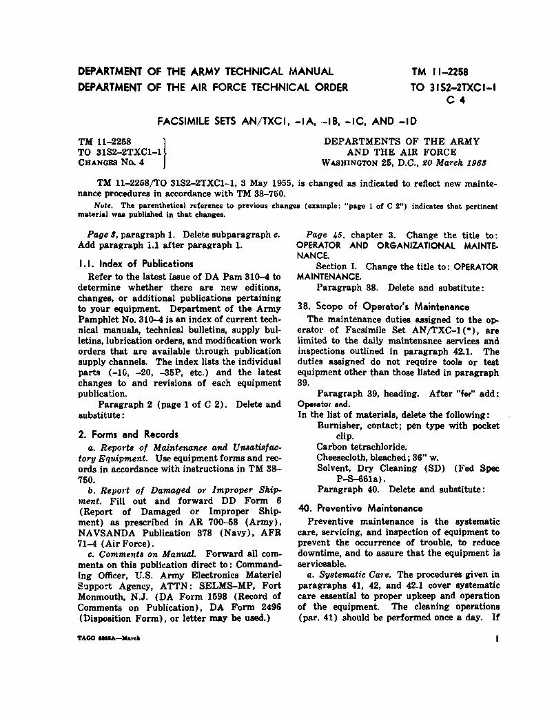
TO31S2-2TXC1-1 TM11-2258 DEPARTMENT OF THE ARMY TECHNICAL MANUAL DEPARTMENT OF THE AIR FORCE TECHNICAL ORDER FACSIMILE SETS AN/TXC-1, -1A -1B, -1C, AND -1D This copy is a reprint which includes current pages from Changes IN FORCE 1.4.5.6.7 DEPARTMENTS OF THE ARMY AND THE AIR FORCE MAY 1955
Transcript of FACSIMILE SETS AN/TXC-1, -1A -1B, -1C, AND -1D · and maintenance of Facsimile Sets AN/TXC-1, 1A,...

TO31S2-2TXC1-1
TM11-2258
DEPARTMENT OF THE ARMY TECHNICAL MANUAL
DEPARTMENT OF THE AIR FORCE TECHNICAL ORDER
F A C S I M I L E S E T S
A N / T X C - 1 , - 1 A
-1B, -1C, AND -1D
This copy is a reprint which includes current
pages from Changes I N F O R C E 1 . 4 . 5 . 6 . 7
D E P A R T M E N T S O F T H E A R M Y A N D T H E A I R F O R C E
MAY 1955

DANGEROUS
W A R N I N G
V O L T A G E S EXIST IN THIS
EQUIPMENT
Be careful when working on the 450-volt plate and power supplycircuits, or on the 115-volt ac line connections. Voltages as highas 1,250 volts ac are developed in the rectifier unit. Voltages upto 1,000 volts ac are developed in the transceiver.
DON’T TAKE CHANCES

C H A N G E
No. 7
Changes in force: C 1, C 4, C 5, C 6, and C 7TM 11-2258
C 7
HEADQUARTERSDEPARTMENT OF THE ARMYWASHINGTON , DC 19 February 1974
FACSIMILE SETSAN/TXC-1, -1A, -1B, -1C, AND -1D
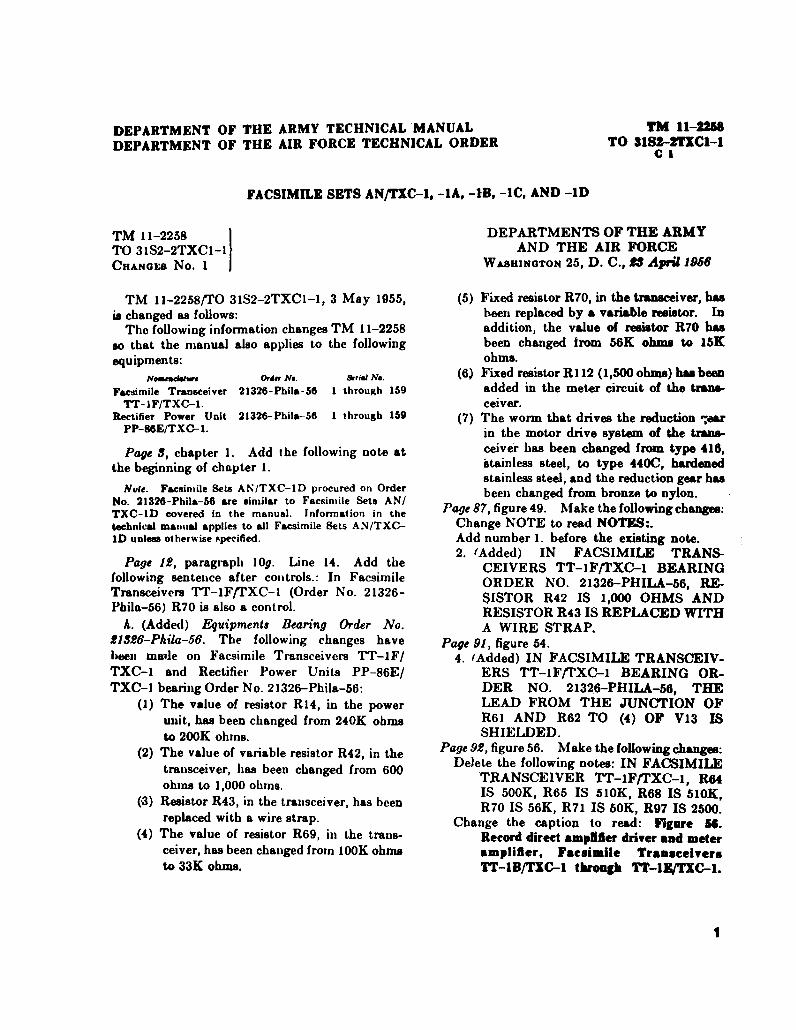
TM 11-2258, 3 May 1955, is changed as follows:Page 3. Paragraph 2 is superseded as follows:
2. Forms and Records
a. Reports of Maintenance and UnsatisfactoryEquipment. Maintenance forms, records, andreports which are to be used by maintenancepersonnel at all maintenance levels are listed inand prescribed by TM 38-750.
b. Report of Packaging and Handling Deficien-cies. Fill out and forward DD Form 6 (Report ofPackaging and Handling Deficiencies) as pre-scribed in AR 700-58 (Army)/NAVSUP PUB 378(Navy)/AFR 71-4 (Air Force)/MCO P4030.29(Marine Corps), DSAR 4145.8.
c. Discrepancy in Shipment Report (DISREP)(SF 361). Fill out and forward Discrepancy in
Shipment Report (DISREP) (SF 361) as prescribedin AR 55-38(Army)/NAVSUPINST 4610.33/AFM75-18/MCO P4610.19A (Marine Corps), and DSAR4500.15.
2.1. Reporting of Errors
The reporting of errors, omissions, and recom-mendations for improving this publication by theindividual user is encouraged. Reports should besubmitted on DA Form 2028 (RecommendedChanges to Publications) and forwarded direct toCommander, US Army Electronics Command,ATTN: AMSEL-MA-C Fort Monmouth, NJ 07703.
Page 6. Paragraph 6.1 is added after paragraph6.
6.1. Items Comprising an Operable Equipment
FSN
5995-161-8710
5995-164-6558
QTY
1
1
Nomenclature, part No., and Mfr code
NOTEThe part number is followed by the applicable 5-digitFederal supply code for manufacturers (FSCM) identifiedin SB 708-42 and used to identify manufacturer, dis-tributor, or Government agency, etc.
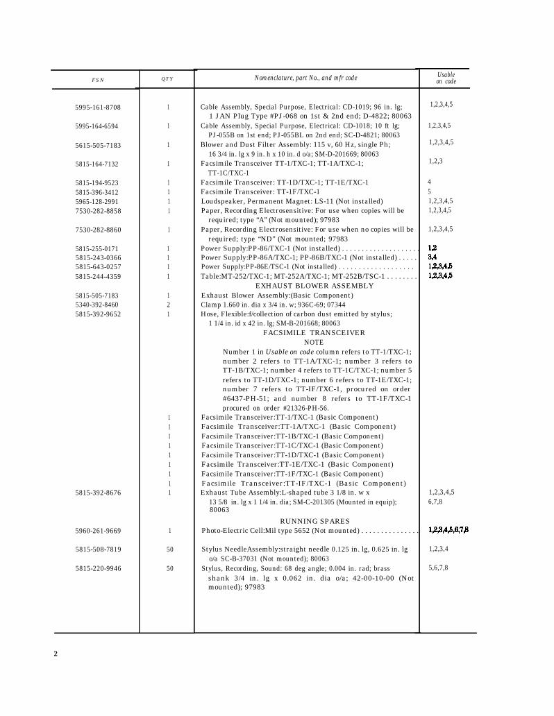
NOTENumber 1 in the Usable on code column refers toAN/TXC-1; number 2 refers to AN/TXC-1A; number 3refers to AN/TXC-1B; number 4 refers to AN/TXC-1C; andnumber 5 refers to AN/TXC-1D.ITEMS COMPRISING AN OPERABLE EQUIPMENT
Cable Assembly, Power, Electrical 2 cond; 8 1/2 in. lg;one PL-55 on 1st end; 2 Mueller Electric alligator clips type"Pee-Wee” #45 on 2nd end #90-37-03; 97983
Cable Assembly, Power, Electrical: 1 cond; 5 ft 9 3/4 in. lgo/a incl terms; 1 GE Plug Part #1346 on 1st end 2 MuellarElectric alligator clips part #60S on 2nd end #90-37-02;97983
Usableon code
1,2,3,4,5
1,2,3,4,5
1
FSN
5995-161-8708 1,2,3,4,5
5995-164-6594
5615-505-7183 1,2,3,4,5
5815-164-7132 1,2,3
5815-194-95235815-396-34125965-128-29917530-282-8858
7530-282-8860
5815-255-01715815-243-03665815-643-02575815-244-4359
5815-505-71835340-392-84605815-392-9652
5815-392-8676
5960-261-9669
5815-508-7819
5815-220-9946
QTY
1
1
1
1
1111
1
1111
121
111111111
1
50
50
Nomenclature, part No., and mfr code
Cable Assembly, Special Purpose, Electrical: CD-1019; 96 in. lg;1 JAN Plug Type #PJ-068 on 1st & 2nd end; D-4822; 80063
Cable Assembly, Special Purpose, Electrical: CD-1018; 10 ft lg;PJ-055B on 1st end; PJ-055BL on 2nd end; SC-D-4821; 80063
Blower and Dust Filter Assembly: 115 v, 60 Hz, single Ph;16 3/4 in. lg x 9 in. h x 10 in. d o/a; SM-D-201669; 80063
Facsimile Transceiver TT-1/TXC-1; TT-1A/TXC-1;TT-1C/TXC-1
Facsimile Transceiver: TT-1D/TXC-1; TT-1E/TXC-1Facsimile Transceiver: TT-1F/TXC-1Loudspeaker, Permanent Magnet: LS-11 (Not installed)Paper, Recording Electrosensitive: For use when copies will be
required; type “A” (Not mounted); 97983Paper, Recording Electrosensitive: For use when no copies will be
required; type “ND’’ (Not mounted; 97983Power Supply:PP-86/TXC-1 (Not installed) . . . . . . . . . . . . . . . . . . . .Power Supply:PP-86A/TXC-1; PP-86B/TXC-1 (Not installed) . . . . .Power Supply:PP-86E/TSC-1 (Not installed) . . . . . . . . . . . . . . . . . . .Table:MT-252/TXC-1; MT-252A/TXC-1; MT-252B/TSC-1 . . . . . . . .
EXHAUST BLOWER ASSEMBLYExhaust Blower Assembly:(Basic Component)Clamp 1.660 in. dia x 3/4 in. w; 936C-69; 07344Hose, Flexible:f/collection of carbon dust emitted by stylus;
1 1/4 in. id x 42 in. lg; SM-B-201668; 80063FACSIMILE TRANSCEIVER
NOTENumber 1 in Usable on code column refers to TT-1/TXC-1;number 2 refers to TT-1A/TXC-1; number 3 refers toTT-1B/TXC-1; number 4 refers to TT-1C/TXC-1; number 5refers to TT-1D/TXC-1; number 6 refers to TT-1E/TXC-1;number 7 refers to TT-IF/TXC-1, procured on order#6437-PH-51; and number 8 refers to TT-1F/TXC-1procured on order #21326-PH-56.
Facsimile Transceiver:TT-1/TXC-1 (Basic Component)Facsimile Transceiver:TT-1A/TXC-1 (Basic Component)Facsimile Transceiver:TT-1B/TXC-1 (Basic Component)Facsimile Transceiver:TT-1C/TXC-1 (Basic Component)Facsimile Transceiver:TT-1D/TXC-1 (Basic Component)Facsimile Transceiver:TT-1E/TXC-1 (Basic Component)Facsimile Transceiver:TT-1F/TXC-1 (Basic Component)Facsimile Transceiver:TT-IF/TXC-1 (Basic Component)Exhaust Tube Assembly:L-shaped tube 3 1/8 in. w x
13 5/8 in. lg x 1 1/4 in. dia; SM-C-201305 (Mounted in equip);80063
RUNNING SPARESPhoto-Electric Cell:Mil type 5652 (Not mounted) . . . . . . . . . . . . . . .
Stylus NeedleAssembly:straight needle 0.125 in. lg, 0.625 in. lgo/a SC-B-37031 (Not mounted); 80063
Stylus, Recording, Sound: 68 deg angle; 0.004 in. rad; brassshank 3/4 in. lg x 0.062 in. dia o/a; 42-00-10-00 (Notmounted); 97983
Usableon code
1,2,3,4,5
451,2,3,4,51,2,3,4,5
1,2,3,4,5
1,2,3,4,56,7,8
1,2,3,4
5,6,7,8
2

Page 7, paragraph 7. Change “Table of Compo- 11.1 Expendable Consumable Itemsnents” to read “Components and Dimensions.”
Page 14. After paragraph 11 add:A list of expendable consumable items requiredfor operation appear in table I.1.
Table 1.1. Expendable Consumable Supplies and Material
The supplies and material listed in this table are required for operation of this equipment and are authorized to be requisitioned by SB700-50. The FSN or the applicable unit of issue required can be found in appropriate supply catalogs. The FSCM is used as an elementin item identification to designate manufacturer or distributor or Government agency, etc., and is identified in SB 708-42.
Item Description Ref. No. FSC
1
and FSCM
Carbon, Granular:activated carbon 1/2 lb can 130-00-00-04 68102 Paper, Recording, Electrosensitive:for use when no ND 7530
copies will be required 979833 Paper, Recording, Electrosensitive:for use when copies A 7530
will be required 97983
Page 200. Appendix III is superseded as follows:
APPENDIX IllBASIC ISSUE ITEMS LIST (BIIL) AND ITEMS TROOP
INSTALLED OR AUTHORIZED LIST (ITIAL)
Section I. INTRODUCTION
1. ScopeThis appendix lists only basic issue items requiredby the crew/operator for installation, operation,and maintenance of Facsimile Sets AN/TXC-1,1A, -1B, -1C, and -1D.
2. General
This Basic Issue Items and Items Troop Installedor Authorised List is divided into the followingsections:
a. Basic Issue Items List-Section II. A list, inalphabetical sequence, of items which are fur-nished with and which must be turned in with theend item.
b. Items Troop Installed or Authorized List-Section III. Not applicable.
3. Explanation of Columns
The following provides an explanation of columnsfound in the tabular listings:
a. Illustration. This column is divided as follows:(1) Figure Number. Indicates
number of the illustration in whichshown.
(2) Item Number. Not applicable
the figurethe item is
b. Federal Stock Number. Indicates the Federalstock number assigned to the item and will be usedfor requisitioning purposes.
c. Part Number. Indicates the primary numberused by the manufacturer (individual, company,firm, corporation, or government activity), whichcontrols the design and characteristics of the itemby means of its engineering drawings, specifica-tions standards, and inspection requirements, toidentify an item or range of items.
d. Federal Supply Code for Manufacturer(FSCM). The FSCM is a 5-digit numeric code usedto identify the manufacturer, distributor, orGovernment agency, etc., and is identified in SB708-42.
e. Description. Indicates the Federal item nameand a minimum description required to identifythe item.
f. Unit of Measure (U/M). Indicates the standardof basic quantity of the listed item as used inperforming the actual maintenance function. Thismeasure is expressed by a two-character al-phabetical abbreviation (e.g., ea, in., pr, etc.) Whenthe unit of measure differs from the unit of issue,
3

the lowest unit of issue that will satisfy the basic issue item furnished with the equipment.required units of measure will be requisitioned. h. Quantity Authorized (Items Troop Installed
g. Quantity Furnished With Equipment (Basic or Authorized Olny). Indicatea the quantity of theIssue Items Only). Indicates the quantity of the item authorized to be used with the equipment.
Section II. BASIC ISSUE ITEMS LIST
(1)Illustration
(A)Fig.no.
(B)Itemno.
(2)Federal
stocknumber
5815-652-8557
5815-406-0794
6810-630-0355
(3)
Partnumber
96-00-22
96-15-22
MIL-AN#V-3
(4)
FSCM
97983
97983
96906
(5)
Description
Usableon code
FACSIMILETRANSCEIVER
COVER, DUST 34 1/2 in.lg x 18 1/2 in. w x 10 1/2 in.h (Mounted in equip)
RECTIFIERPOWER UNIT
COVER, POWER SUP-PLY:12 1/2 in. lg x 10 1/2in. w x 10 in. h (Mountedin equip)
EXHAUST BLOWERASSEMBLY
BAG:Filter cloth construc-tion; used as dust bag inexhaust system
(6)Unitof
meas
EA
EA
EA
(7)Qtyfurnwith
equip
1
1
4
4

By Order of the Secretary of the Army:
Official:VERNE L. BOWERSMajor General, United States ArmyThe Adjutant General
Distribution:Active Army:
USASA (2)CNGB (1)ACSC-E (2)Dir of Trans (1)COE (1)TSG (1)USAARENBD (1)USAMB (10)AMC (1)MICOM (2)TECOM (2)TRADOC (2)ARADCOM (2)ARADCOM Rgn (2)Os Maj Comd (4)LOGCOMD (3)USACC (4)
C R E I G H T O N W . A B R A M S
General, United States ArmyChief of Staff
USACC-Europe (5)USACDCEC (10)HISA (ECOM) (18)MDW (1)Armies (2)Corps (2)Instl (2) except
Ft Gordon (10)Ft Huachuca (10)Ft Carson (5)Svc Colleges (1)USASESS (20)USASCS (10)USAINTS (3)USAADS (2)USAFAS (2)USAARMS (2)USAIS (2)USAES (2)AD (2) except
SAAD (30)
ARNG: State AG (3).USAR: None.For explanation of abbreviations used, see AR 310-50.
LBAD (14)TOAD (14)ATAD (10)
Gen Dep (2)Sig Sec, Gen Dep (2)Sig Dep (2)USASATC&S (2)APG (2)ATS (1)MAAG (1)WRAMC (1)USARMIS (1)USAERDAA (1)USAERDAW (1)Sig FLDMS (1)Ft Richardson (ECOM Oft) (2)Units org under fol TOE (1 ea.):
711-3511-3711-9511-9711-9811-9911-11711-12711-13711-14711-15811-34511-500(AA-AC)1729-13429-1363754-12,54-2254-202
5


TM 9-213.
TM 38-750
TM 9-213


TECHNICAL MANUAL
No. 11-2258TECHNICAL ORDER
No. 31S2-2TXC1-1
CHAPTER 1.Section I.
II.CHAPTER 2.
Section I.II.
III.IV.
CHAPTER 3.Section I.
II.III.IV.
V.CHAPTER 4.
Section I.II.
CHAPTER 5.Section I.
II.III.
CHAPTER 6.Section I.
II.III.IV.
V.VI.
CHAPTER 7.
Section I.II.
INDEX -----
FACSIMILE
INTRODUCTIONGeneral
*TM 11-2258/TO 31S2-2TXC1-1
DEPARTMENTS OF THE ARMY ANDTHE AIR FORCE
W ASHINGTON 25, D, C., 3 May 1955
SETS AN/TXC-1, -1A, -1B, -1C, and -1D
Paragraph1,2
Description and data. ---------------------------------------------------------- 3-11OPERATIONService upon receipt of Facsimile Set AN/TXC-1(*)--------------------------------- 12-20Controls and instruments -------------------------------------------------------- 21,22Operation under usual conditions -------------------------------------------------- 23-33Operation under unusual conditions --------------------------------------------- 34-37ORGANIZATIONAL MAINTENANCEOrganizational tools and equipment ----------------------------------------------- 38,39Preventive maintenance services ------------------------------------------------- 40-43Lubrication --------------------------------------------------------------------- 44-47Weatherproofing ---------------------------------------------------------------- 48-53Troubleshooting at organizational maintenance level --------------------------------- 54-58AUXILIARY EQUIPMENTConverter CV-2C/TX -------------------------------------------------------------- 59,60Exciter Unit O-5B/FR ----------------------------------------------------------- 61-64THEORYGeneral ------------------------------------------------------------------------ 65-68Facsimile Transceiver TT-1(*)/TXC-1 -------------------------------------------- 69-79Rectifier Power Unit PP-86(*)/TXC-1. ------------------------------------------- 80-82FIELD MAINTENANCETroubleshooting at field maintenance level - - - - - - - - - - - - - - - - - - - - - - ---- 83-86Trouble analysis-- - - - - - - - - - - - - - - - - - - - - - - - - - - - - - - - - - - - - - - - - - - - - - - - - - - - -87-102Repair and adjustments --------- -------------------------------------------------- 103-123Emergency repairs and operation--------------------------------------------------------------------------- 124-134Disassembly and lubrication of equipment at field maintenance level . . . . . . . . . . . . . . . . 135-139Final testing . . . . . . . . . . . . . . . . . . . . . . . . . . . . . . . . . . . . . . . . . . . . . . . . . . . . . . . . . . . . . . . . . . 140-142SHIPMENT AND LIMITED STORAGE AND DEMOLITION TO PREVENT
ENEMY USEShipment and limited storage . . . . . . . . . . . . . . . . . . . . . . . . . . . . . . . . . . . . . . . . . . . . . . . . . . . 143,144Demolition of materiel to prevent enemy use . . . . . . . . . . . . . . . . . . . . . . . . . . . . . . . . . . . . . 145,146
33-12
15-2324
29-4044
4545,4649,5050-5252-54
5859-61
64-7172-100
102-104
108-110110-144144-173173-175176-177
178
200200
225-229
*This manual supersedes TM 11-2258, 15 December 1947, including C 1, 29 June 1950.
1

Figure 1. Facsimile sets AN/TXC-1, -1A, -1B, and -1C
2

CHAPTER 1
INTRODUCTION
Section I. GENERAL
1. Scope
a. This manual contains instructions for theinstallation, operation, maintenance, and repair ofFacsimile Set AN/TXC-1(*) (figs. 1 and 2).Descriptions of and data for Facsimile Set AN/TXC-1(*) and auxiliary equipment also areincluded.
b. Official nomenclature followed by the symbol(*) is used to indicate all models of the item ofequipment included in this manual. FacsimileSet AN/TXC-1 (*) refers to Facsimile Sets AN/TXC-1, -1A, -1B, -1C, and -1D. FacsimileTransceiver TT-1(*)/TCX-1 refers to FacsimileTransceivers TT-1/TXC-1, TT-1A/TXC-1, TT-1B/TXC-1, TT-1C/TXC-1, TT-1D/TXC-1, TT-1E/TXC-1, and TT-1 F/TXC-1; Rectifier PowerUnit PP-86(*)/TXC-1 refers to Rectifier PowerUnits PP-86/TXC-1, PP-86A/TXC-1, PP-86B/TXC-1, and PP-86E/TXC-1; Table MT-252(*)/TXC-1 refers to Tables MT-252/TXC-1,MT-252A/TXC-1, and MT-252B/TXC-1.
c. Forward comments on this publication direct-ly to: Commanding Officer, The Signal CorpsPublications Agency, Fort Monmouth, NewJersey, ATTN: Standards Division.
2. Forms and RecordsThe following forms will be used for reporting
unsatisfactory conditions of Army equipment andin performing preventive maintenance.
a. DD Form 6 (Report of Damaged or Im-proper Shipment) will be filled out and forwardedas prescribed in SR 745-45-5 (Army) and AFR-71-4 (Air Force).
b. DA Form 468 (Unsatisfactory EquipmentReport) will be filled out and forwarded to theOffice of the Chief Signal Officer as prescribed inSR 700-45-5.
c. DD Form 535 (Unsatisfactory Report) willbe filled out and forwarded to CommandingGeneral, Air Materiel Command, Wright-Patter-son Air Force Base, Dayton, Ohio as prescribedin SR 700-45-5 and AF TO 00-35 -54.
d. DA Form 11-238 (Operator First EchelonMaintenance Check List for Signal Corps Equip-ment-Radio Communication, Direction Finding,Carrier, Radar) will be prepared in accordancewith instructions on the back of the form (fig. 24).
e. DA Form 11-239 (Second and Third EchelonMaintenance Check List for Signal Corps Equip-ment-Radio Communication, Direction Finding,Carrier, Radar), will be prepared in accordancewith instructions on the back of the form (fig. 25).
f. Use other forms and records as authorized.
Section Il. DESCRIPTION AND DATA
3. Purpose and Use
Facsimile Set AN/TXC-1(*) is an electro-mechanical-optical facsimile set of the revolvingdrum type for the transmission and reception ofpage copy. It is used for transmission of maps,photographs, sketches, and printed or handwrittentext over regular voice communication channels,either wire or radio, between fixed stations.Although colored copy may be transmitted, thereproduction is always in black, white, and inter-mediate shades of gray. Received copy is-recorded
either directly on chemically coated paper orphotographically in either negative or positiveform. The equipment will transmit or receivea page of copy 12 by 18 inches in 20 minutes;Facsimile Sets AN/TXC-1D, -1E, and -1F haveprovisions for transmitting or receiving copy athalf speed. When set for half-speed operation,they will transmit or receive one page of copyin 40 minutes. Principal components of FacsimileSet AN/TXC-1(*) (figs. 1 and 2) are FacsimileTransceiver TT-1(*)/TXC-1 which serves eitheras transmitter or receiver (depending on the setting
3

of a front panel selector switch) and RectifierPower Unit PP-86(*)/TXC-1 (fig. 3) whichsupplies operating power to the transceiver anddust removal blower and operates from analternating-current (ac) source of 115 volts at 60cycles per second (cps).
4. Application of Facsimile Set AN/TXC-1(*)
Facsimile Set AN/TXC-1(*) may be used witheither wire or radio communication circuits.
a. Wire Circuits. When used with wire lines,the facsimile transceiver can be connected directlyto the line by one of several input and outputterminals of various impedances and levels. Thetransceiver also can be connected to the linethrough a coupling coil, which may be coupledmagnetically to the receiver of a conventional
telephone handset or which may be coupledinductively to certain types of lines that have noringing or signaling circuits. An amplitude-modulated (am.) 1,800-cycle carrier is transmittedand received.
b. Radio Circuits. When used with radio com-munication circuits, the facsimile transceiver canbe connected in several ways with auxiliaryequipment to produce different types of radiosignals.
(1) Subcarrier amplitude modulation (SCAM),When transmitting, the facsimile trans-ceiver is connected to the microphonecircuit of a conventional am radiotele-phone transmitter to produce an amradio signal. When receiving, the out-put of a conventional am radio receiver
Figure 2. Facsimile set AN/TXC-1D.
4

is connected to the input of the facsimiletransceiver.
(2) Subcarrier frequency modulation (SCFM).When the facsimile transceiver is con-nected to such auxiliary equipment asConverter CV-2(*)/TX, the converteroutput is fed into a conventional amradiotelephone transmitter and the radiosignals are described as narrow bandsubcarrier frequency modulation. Theradio signals consist of a radio-frequency(rf) carrier modulated by a constant-amplitude audio signal, the frequency ofwhich is varied to carry facsimile intelli-gence. When this system is used forreceiving, a conventional am radioreceiver, the same converter, and thesame facsimile transceiver are used.The converter changes the subcarrierfm signals back to am signals, which arerequired for operation of the transceiver.
(3) Frequency-shijt modulation. When Fac-simile Transceiver TT-1(*)/TXC-1 isused with two auxiliary equipments,
Converter CV-2C/TX and Exciter UnitO-5B/FR (earlier models must be modi-fied) frequency-shift signals can be trans-mitted over a conventional continuous-wave (cw) radio transmitter. Whentransmitting, the am output of FacsimileTransceiver TT-1(*)/TXC-1 is fed intothe converter. A varying direct-current(dc) output is taken from the converterand fed into frequency-shift ExciterUnit O-5B/FR. The output of theexciter unit excites the cw transmitterand a frequency-shift radio signal istransmitted. When receiving, a stableam communication receiver with acrystal-controlled, high-frequency (hf)oscillator and the converter are used toconvert the frequency-shift signals to amsignals. When using receivers that donot use crystal-controlled conversion, thestable output of additional auxiliaryequipment Frequency Meter BC-221 isrequired and is used with Converter CV-2C/TX to receive frequency-shift signals.
Figure 3. Rectifier power units PP-86/TXC-1, PP-86A/TXC-1, or PP-86B/TXC-1, cover removed.
5

5. Technical Characteristics
a. Facsimile Transceiver TT-1(*)/TXC-1.
Type of equipment. . . . .Functions. . . . . . .. . . . .
Type of copy . . . . . . . . . . . . .Maximum size of copy . . . Size of scanning spot . . . . . .Type of recording. . . . . . .
Drum diameter . . . . . . Speed of drum:
Rotation .. . . . . . . . . .
Lateral movement . . . . .
Scanning lines per inch.Index of cooperation.. .Number of tubes . . . ...
Weight(lb)
Audio carrier frequency.Type of modulation.......Frequency bandwidth .....Frequency band limits .. ..Drum speed control . . . . .
339
Signals levels:Input, (for reception...Output (for transmis-
sion).
Rotating drum type.Transmitting or receiving
signals.Page.12 by 18 11/16 inches.1/96 inch.Direct, or photographic posi-
tive or negative.6 inches.
1 revolution per second inthe -1, -1A, -1B, and -1Cmodels; ½ or 1 revolutionper second in the -1D,-1Ei and -1F models.
12 inches in 20 minutes in –1,-1A,-1B,and-1C models;12 inches in 20 minutes or40 minutes in -1D, -1E,and-1F models.
96.576.18 in -1, -1A, -1B, and -1C
models; 19 in -1D, -1E,and -1F models.
1,800 cps.Am.1,800 cps maximum.900 to 2,700 cps.Synchronous motor con-
trolled by 1,800-cps forkoscillator, or 900-cps mul-tivibrator (or external au-dio source).
-45 to 0 dbm.0 to +26 dbm.
b. Rectifier Power unit PP-86(*)/TXC-1.Number of tubes .........Input requirements:
Power source ........
Signal source ........
Output:Unregulated plate sup-
ply.Filament supply .......Start motor supply . ..Exciter lamp supply ...
Dust removal blower...
6. Packaging Data
7.
100 to 130 v, 50 to 65 cps;250 w; at 115 v.
1,800 cps from fork oscil-lator.
450 v at 270 ma.
6.5 V, ac at 6.25 amperes.115 v, ac at .5 ampere.Regulated 6 v, 1,800 cps at
2.74 amperes, ±.1 v.115 v, 60 cps, 3 amperes.
When packaged for export shipment, the com-ponents of Facsimile Set AN/TXC-1(*) are placedin water-vaporproofed containers and are packedin four wooden crates. Typical packaging pro-cedure of Facsimile Transceiver TT-1 (*)/TXC-1is shown in figure 7. The size, weight, and volumeof each crate are indicated in the following chart:
Note. Items may be packaged in a manner differentfrom that shown, depending on the supply channel.
BoxNo.
1 of 4
2 of 4
3 of 4
4 of 4
Contents
Facsimile Trans-ceiver TT-1(*)/TXC-1 and spareparts.
Rectifier PowerUnit PP-86(*)/TXC-1 and spareparts.
Photographic Equip-ment PH-549/TXC-1.
Table MT-252(*)/TXC-1.
Dimensions(in.)
40½ x 15½ x22½.
17½ x 15 x15¼.
40 x 26 x 26
40 x 26 x 41
Volume(cu ft)
8.1
2.3
15.6
11.5
218
89
137
6

7. Table of Components(figs 1-6)
(*)
(*)(*)
(*)(*)(*)
(*)(*)
(*)(*)(*)(*)(*)
(*)
(*)(*)
(*)(*)
(*)
Facsimile set
( * )
(*)(*)(*)(*)
(*)(*)(*)(*)(*)(*)(*)(*)(*)(*)
(*)
(*)
(*)(*)
(*)
(*)
(*)(*)(*)(*)(*)
(*)(*)
(*)(*)
(*)(*)(*)(*)
(*)
(*)
(*)
(*)
(*)(*)
(*)
(*)(*)(*)(*)(*)(*)(*)(*)(*)
(*)(*)(*)
(*)(*)(*)(*)
(*)(*)(*)
(*)(*)
(*)(*)(*)(*)
(*)(*)(*)
(*)(*)
(*)(*)
(*)(*)
(*)(*)(*)(*)
(*)
(*)(*)(*)
Component
Facsimile Transceiver TT-1/TXC-1 Facsimile Transceiver TT-1A/TXC-1Facsimile Transceiver TT-1B/TXC-1 or TT
1C/TCC-1.Facsimile Transceiver TT-1D/TXC-1 or TT
1E/TXC-1.Facsimile Transceiver TT-1F/TXC-1Rectifier Power Unit PP-86(*)/TXC-1Photographic Equipment PH-549/TXC-1Table MT-252(*)/TXC-1Paper, direct recordingPaper, direct recording, hectograph processCord CD-1018C o r d C D - 1 0 1 9Cable assembly, special purposeCable assembly, special purpose, electricalClips, alligatorCoupler, induction, UCCover, dust (transceiver)Cover, dust (power unit)Loudspeaker LS-11L a m p L M - 5 2Weighing scale 2 to 24 ounces (avoirdupois)S c r e w d r i v e rWrench, Allen #6W r e n c h , T L - 5 0 7 / UTM 11-2258Tube extractorFuse, 3 amperesBlower and dust filter assembly including filter
bag.Can of activated carbonFlexible hoseHose clamps
RequiredNo.
111
1
111111111121111111112165
212
Height(in.)
10 ¼10 ¼10 ¼
10 ¼
10 ¾9
32
4 ¼
Depth(in.)
17 5/8
17 5/8
17 5/8
17 5/8
17 5/8
10
22
2
4 2
Length(in.)
34 5/8
34 5/8
34 5/8
34 5/8
34 5/8
12
3 7
1209666
6
6
4
2½
Volume(cu ft)
3.53.53.5
3. 5
3 . 562
4.7
Unitweight
(lb)
858585
85
85488386
18
Note. This list is for information only. See appropriate supply publications for information pertaining to requisi-tioning of spare parts.
8. Description of Componentsa. Facsimile Transceiver TT-1(*)/TXP-1. All
models of Facsimile Transceiver TT-1(*)/TXC-1are similar in size, weight, and appearance. Theydiffer slightly in the number of operating controlsand in certain circuit features. The transceiveris mounted on a steel chassis 345/8 inches long,175/8 inches deep, and 10¾ inches high. Tubularguards, 1 inch in diameter, are welded to each endof the chassis to serve as carrying handles and toprotect the equipment when it is turned on its
side, back, or top for inspection and repair.Mounted to the chassis are the motor assembly,bearings that support the lead screw and drum,fork oscillator unit, regulator unit, signal andphasing circuit components, transmitting opticalsystem, receiving optical system, indicatingmeters, and various other components. Thepower supply connection plug and the panel sup-porting the operating controls and terminal panelalso are mounted on the chassis. Operating con-trols are located on a sloping portion of the front
7

panel, behind the drum. The terminal panel forinput and output connections is on the right sideof the panel assembly. An output jack for con-necting an external speaker in the voice commu-nication (talk-back) circuit is located on the leftside of the panel assembly on all transceiver unitsexcept Facsimile Transceiver TT-1/TXC-1 (referto note in g below). The transceiver is providedwith a metal base cover, which is attached to thechassis with machine screws and which has fourmetal supporting feet. Metal covers that protectthe motor and clutch assembly and the rear, side,and top of the transceiver are held in place withslide fasteners. A canvas cover is provided toprotect the transceiver from dust when it is not inuse. Facsimile Transceiver TT-1F/TXC-1 hasan exhaust duct that runs from the vicinity of thestylus to the right rear of the chassis.
b. Rectifer Power Unit PP-86(*)/TXC-1. Therectifier power unit (fig. 3) is constructed on ametal chassis 12 inches long by 10 inches wide by2½ inches high (some chassis are 3 inches high).All components are mounted on top of the chassis.The chassis is shielded and protected by a metalventilated top cover and by a bottom cover platewith four metal feet. Two cables emerge froman opening in the top cover; one is a power cablefor connecting to the ac line, and the other is apower cable that is terminated in a Jones plugattached to the transceiver. The rectifier powerunit is provided with a canvas cover for protectionduring shipping. Rectifier Power Unit PP-86E/TXC-1 has a receptacle (J10) with a ground studfor the dust removal blower power cord. Thefuse holder which housed the spare fuse in allformer models of the rectifier power unit now isused for the 3 amp 3AG dust removal blowerfuse (XF4, fig. 156).
Caution: Do not leave the cover on the powerunit during operation or components will overheat.
c. Table MT-252(*)/TXC-1. The collapsiblemetal table (fig. 1) furnished with each facsimileset is 32 inches high, 22 inches deep, and 37 incheslong. It can be disassembled by removing themetal screws in the legs and side braces. Thetable has a masonite top on which FacsimileTransceiver TT-1(*)/TXC-1 is mounted. A bot-tom shelf supports Rectifier Power Unit PP-86(*)/TXC-1 and auxiliary equipments ConverterCV-2(*)/TX and Exciter Unit 0-5(*)/FR (whenused). A hole in the top of the table permitseasy connection of the power cable plug to thetransceiver. It also permits passage of the flexible
8
hose for the dust removal system from the ducton the transceiver to the blower and canisterassembly which is clamped to the bottom shelfand right-hand leg brace of the table (fig. 2). Ametal drawer is provided for storing a supply ofrecording paper.
d. Photographic Equipment (fig. 4). Photo-graphic Equipment PH-549/TXC-1 is suppliedwith Facsimile Transceiver AN/TXC-1*. Thisequipment consists of one thermometer, fourBottles PH-22, and four trays.
e. Cords and Leads. The following cords andleads (fig. 5) are furnished with Facsimile SetAN/TXC-1(*):
(1) Cord CD-1018, a 10-foot, two-conductor,
(2)
(3)
(4)
shielded, rubber-jacketed cord, term-nated at each end with Plug PL-55. Itis used in making input connections tothe transceiver.Cord CD-1019 an 8-foot, three-conductor,shielded, rubber-jacketed cord, termi-nated at each end with Plug PL-68. Itis used in making output connectionsfrom the transceiver.A 5½-foot test lead terminated on oneend with a two-prong plug that fits the1V and 6V jacks on the coupling coil(fig. 6), and on the other end with twoalligator clips. It is used in makinginput and output connections to thetransceiver when a high-level signal isrequired for certain types of wire lines.A 6-inch test lead a two-conductor cordterminated at one end with PL-55, andat the other end with two alligator clips.It is used in connecting a wire line intothe RADIO RCVR jack during receptionof high-level signals.
f. UC Coupling Unit. This coupling unit (fig.6) is used to make input and output connectionsto the transceiver through a telephone receiver,and is supplied with a phosphor-bronze clamp forholding it in place on the telephone handset. Theprimary impedance is 600 ohms and matches theoutput of the transceiver. The full 10-ohmsecondary provides an open-circuit output of 6volts; the secondary also has a 2-ohm tap thatprovides an open-circuit voltage of 1 volt. Thesecondary terminates in two female type plugs forselection of the desired level. This unit is notused with Facsimile Transceiver TT-1F/TXC-1.
g. Loudspeaker LS-11 (fig. 5). This loud-speaker is used in the talk-back circuit of Facsimile

Figure 4. Photographic equipment PH-549/TXC-1.
Sets AN/TXC-1B, -1C, and -1D, and also inFacsimile Set AN/TXC-1A when modified accord-ing to MWO SIG 11-375B-(1), Modification ofFacsimile Set AN/TXC-1A to Provide anExternal Loudspeaker (par. 11).
Note. Facsimile Set AN/TXC-1 contains no talk-backcircuit. MWO SIG 11-2258-1, Modification of FacsimileSets AN/TXC-1 to Provide an Audible Signaling Device,gives instructions for connecting a jack to add a loud-speaker to Facsimile Set AN/TXC-1. The tones thatprecede a facsimile transmission will then be audible tothe receiving operator. This external speaker is of thepermanent magnetic type, 4 inches in diameter, with a250-ohm output transformer to match the impedance ofthe transceiver talk-back circuit. The speaker and trans-former are contained within a steel box which is 45/8 incheshigh, 45/8 inches wide, and 2 inches deep. This box isfitted with a mounting clamp.
h. Recording Paper (fig. 5). Two special typesof direct recording paper are furnished for use withFacsimile Transceiver TT-1(*)/TXC-1.
(1)
(2)
Teledeltos paper or Timefax NDA is usedin direct recording. They are dry paperswith dark undercoating and light topcoating. The coating is burned off by aspark from the transceiver stylus duringthe direct recording operation. Thepaper furnished is 12 inches by 1811/16
inches in size. Four packages, each con-taining 250 sheets of Teledeltos grade H,or Timefax NDA, are furnished. Thispaper is nonduplicating.Timefax A paper is used in the directrecording process when multiple copies
of the received pictures are to be madewith a hectograph pad. This is aspecially prepared paper containing adye coating with a high-resistance outercoating that is burned by the spark fromthe transceiver stylus. The paper fur-nished is 12 inches by 1811/16 inches insize. Two packages, each containing250 sheets, are furnished.
9. Running SparesRunning spares are supplied with Facsimile Set
AN/TXC-1(*) and are packed in the crate thatcontains the component in which they are used.Spares are supplied for all normally expendableitems such as tubes, pilot lamps, and fuses. Thefollowing is a list of the items supplied:
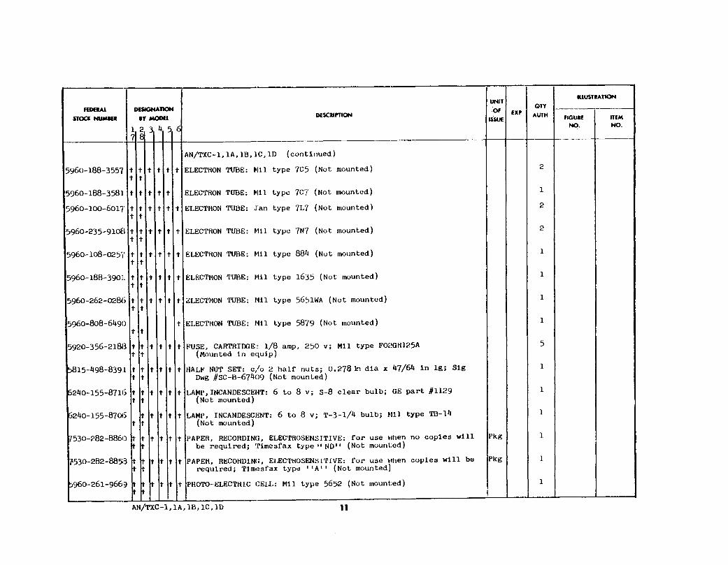
1 tube, type 1B461 tube, type 1B471 tube, type 6AC5GT/G3 tubes, type 7C51 tube, type 7C73 tubes, type 7L72 tubes, type 7N71 tube, type 7S71 tube, type 5Z31 tube, type 8842 tubes, type RMA R1130B2 tubes, type 16351 tube, type 16454 tubes, type 56511 tube, type 56521 tube, type 5879
9

Figure 5. Facsimile set AN/TXC-1*, accessories.
100 styluses12 fuses, 1/8-ampere5 fuses, 3-ampere6 fuses, 5-ampere6 lamps, 6 to 8 volts2 sets split nuts1 reduction worm gear*1 motor shaft worm gear*1 worm gear taper screw*4 filter bags1 can of activated carbon
10. Differences in ModelsFacsimile Sets AN/TXC-1, -1A, -1B, -1C, and
-1D are similar in purpose, operation, and ap-
*Gears not replaceable in Facsimile Sets AN/TXC-1, -1A, and -1B.
10
pearance. The later models (1A, 1B, 1C, and 1D)include a number of improvements which arelisted in a through g below and in table I.
a. Fork Oscillator Unit. This unit is unsealedin Facsimile Set AN/TXC-1, serial numbers upto 105, on Order No. 2695-MPD-45. Startingwith serial number 105, a sealed fork oscillatorunit is used in the transceiver of the remainingmodels of Facsimile Set AN/TXC-1 and in allmodels of Facsimile Sets AN/TXC-1A, -1B, -1C,and -1D. The sealed fork unit includes a revisedtube line-up. The fork is sealed against changesin pressure and humidity. Details of both sealedand unsealed units are given in paragraphs 69and 70. The two units are interchangeable elec-trically and mechanically.

Figure 6. UC coupling coil.
b. Talk-Back Circuit. Facsimile Set AN/TXC-1includes no talk-back circuit. Communication be-tween transmitting and receiving operators is bymeans of external telephones, which may use thesame wire or radio circuit as the facsimile equip-ment. All models of Facsimile Set AN/TXC-1Aoriginally were produced with a built-in loud-speaker serving as both microphone and loud-speaker, the change-over of function being accom-plished by a STANDBY-MON-TALK switch onthe front panel. All models of Facsimile SetAN/TXC-1A modified by MWO SIG 11-375B-(1)contain a jack into which an external LoudspeakerLS-11 may be plugged to improve the quality ofvoice communication. Refer to figure 165 fordetails of this modification. All models of Fac-simile Sets AN/TXC-1B, -1C, and -1D have onlythe external Loudspeaker LS-11. The built-inspeaker and speaker transformer used in FacsimileTransceiver TT-1A/TXC-1 have been eliminated.The STANDBY-MON-TALK switch is used onFacsimile Sets AN/TXC-1A, -1B, -1C, and -1D.
c. Synchronous Motor. Motors on all fourequipments are interchangeable mechanically,but motor parts are not interchangeable. All aresynchronous motors, controlled by an 1,800-cpssignal generated in the fork oscillator unit, and
are increased in power by the motor amplifiertubes. Facsimile Transceivers TT-1B/TXC-1through TT-1F/TXC-1 each use an induction-type start motor that operates from a 115-volt,60-cps source supplied by Rectifier Power Unit,PP-86A/TXC-1, PP-86B/TXC-1, or PP-86E/TXC-1. Facsimile Transceivers TT-1/TXC-1and TT-1A/TXC-1 originally used start motorsthat operated from a 9-volt, 60-cps supply,applied when the START button on the trans-ceiver is pressed. Starting voltage for thesemotors was supplied by Rectifier Power UnitPP-86/TXC-1. All of the 9-volt KBA-1 motorsin Facsimile Transceivers TT-1/TXC-1 andTT-1A/TXC-1 were replaced with 115-volt acinduction-type KBA-2 motors similar to thoseused in the later models, and Rectifier PowerUnit PP-86/TXC-1 was modified to supply the115-volt starting voltage. These modificationswere accomplished by application of MWOSIG 11-2258-2, Modification of Facsimile SetsAN/TXC-1 and AN/TXC-1A to Eliminate Motorand Tube Failure and to Improve VoltageRegulation.
d. Resistance and Capacitance Values. Valuesof resistors and capacitors in Facsimile SetAN/TXC-1 were based on old standards. The
11

value of numerous individual components haschanged slightly in Facsimile Sets AN/TXC-1A,-1B, -1C, and -1D to conform with AmericanWar Standards values. In most cases, the differ-ences are less than the plus or minus 10 percenttolerances of the components, and are of nosignificance.
e. Rectifier Power Unit PP-86(*)/TXC-1.Rectifier Power Unit PP-86/TXC-1, a componentof Facsimile Sets AN/TXC-1 and AN/TXC-1A,will operate Facsimile Transceiver TT-1/TXC-1or TT-1A/TXC-1, but will not operate FacsimileTransceiver TT-1B/TXC-1, TT-1C/TXC-1, TT-1D/TXC-1, TT-1E/TXC-1, or TT-1F/TXC-1,unless modified. Rectifier Power Units PP-86A/TXC-1 and PP-86B/TXC-1 will operateFacsimile Sets AN/TXC-1 through AN/TXC-1C.Rectifier Power Unit PP-86E/TXC-1 will operateall models of the transceiver and has provision forsupplying power for the dust removal blowersupplied with Facsimile Set AN/TXC-1D.
f. Table MT-252A/TXC-1. Tables MT-252A/TXC-1 and MT-252B/TXC-1 are the same si eas Table MT-252/TXC-1. The construction andmethod of dismantling the three models differslightly.
g. Transceiver Differences. Facsimile Trans-ceiver TT-1F/TXC-1 is similar to FacsimileTransceiver TT-1E/TXC-1 as listed in table I,except in the following respects. In the -1F model,an automatic stop circuit is incorporated tode-energize the synchronous drive motor andground the amplified facsimile signal at the endof drum travel. A duct has been placed to helpremove dust from the vicinity of the stylus duringthe record direct operation. The paper clamp bar isplastic insulated to reduce spurious rf radiationgenerated as the stylus passes across the clampbar. This model includes R64, R71, R107, andR318 controls. Differences in Facsimile Trans-ceivers TT-1/TXC-1 through TT-1E/TXC-1are listed in table I.
11. Modifications
Certain parts of Facsimile Set AN/TXC-1(*)and Rectifier Power Unit PP-86/TXC-1 have beenmodified as listed below. To determine whetheror not the equipment in use has been modified,indications will be shown by markings on modifiedequipment or by the schematic diagrams foundon the bottom plates of transceivers and rectifierpower units.
12
a. MWO SIG 11-375B-(1) (fig. 165).(1) The purpose of this modification is to
provide an external loudspeaker forFacsimile Transceiver AN/TXC-1A.
(2) The talk-back circuit is the part modified.b. MWO SIG 11-2258-1.
(1) The purpose of this modification is tomake audible to the receiving operatorthe tones that precede a facsimile trans-mission. This is accomplished by re-wiring the existing standby circuit toinclude a loudspeaker in Facsimile SetAN/TXC-1.
(2) The receiving and standby circuits aremodified.
c. MWO SIG 11-2258-2 (fig. 163).(1) The purposes of this modification are:
(a)
(b)
(c)
(d)
To- eliminate motor failure by provid-ing a new and improved type motor.To install a meter and a control forproper motor current indication andadjustment.
To prevent possible failure of amplifiertubes by installing a voltage droppingresistor and replacing tubes type6AG5GT/G with tubes type 1635.To prevent fluctuation of the inputsignal to the motor power tubes byincorporating an adjustment control,indicating meter, and new regulatinglamp in the regulated B voltagecircuit.
(2) Facsimile Transceivers TT-1/TXC-1 and-1A and Rectifier Power Unit PP-86/TXC-1 are the major items affected.
d. MWO SIG 11-2258-3.(1)
(2)
The purpose of this modification is toprovide a replaceable worm and gear,when the worm and worm gear becomeworn out, and when it is necessary toreplace the decoupling springs betweenthe synchronizing and start rotors withsprings of improved design.Facsimile motor model KBA-1 is themajor item affected.
e. MWO SIG 11-2258-5.(1)
(2)
The purpose of this modification is toprovide an improved type motor and newmounting studs to be used on FacsimileTransceiver TT-1C/TXC-1 as made byEspey.Facsimile Transceiver TT-1C/TXC-1 isthe major item affected.
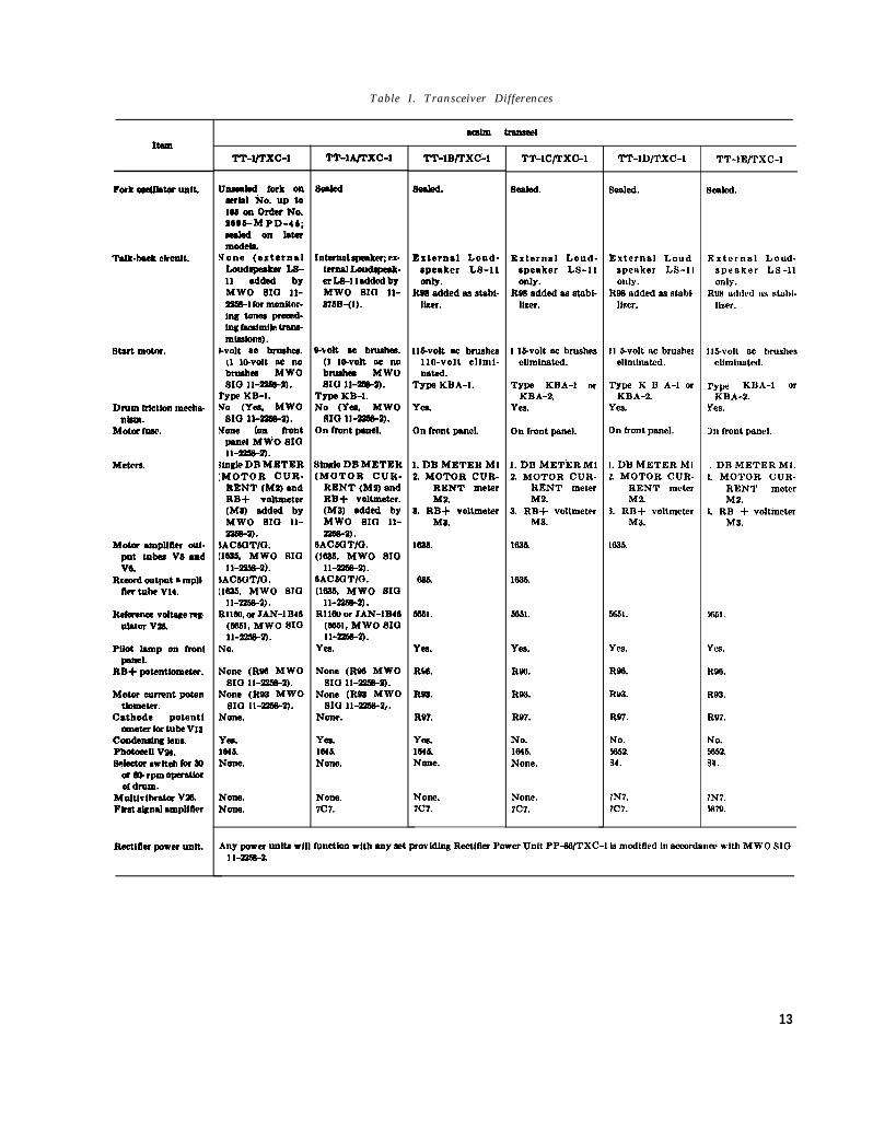
Table I. Transceiver Differences
Item
Fork omtfMor unit.
Tdk-tmek Clreatt.
Stwt motor.
Dmm frlettmr meelmrtbrrr.
Motor frmv.
Mders.
Mow UX@ittW out.fnx tubes W andV6.
Rmrrd output ● mpli.n- tube V14.
Refemelee Voltsge rerUfsitnr V26.
Pilot hmp on frmrlpnnel.
RB+ potentiometer.
Motor -nt potartfometer.
Cathode potentlometer for tube V18
Ctmdermlng brmPbOtOmff V24.Sefectcr IWltob for 60
or 60 rpm ofnmttmof drum.
Multlvlfwstor V26.Ftrat slgnaf urtplftlvr
Rr$tltler power unit.
Tlwrxc-1
Unxeded fork onsertd No. UP to
106 on Order No.2606-M PD-46;eededonfatermodeb.
None (externalbrrd~ LS-11 edded byMWO S10 11-22tR-1 for monltOr-Jng tomw preeed-tng famlmlfe trrms-mlxdlmw).
)-volt ~0 brudmx.(1 m-volt ee nobruxbes MWOSIG 11-2256-2).
TYV KB-I.No (Yes, MWO
S10 11-226%2).None (rm front~el MWO SIO11-2256-2).
3tnfrfe DB METER[MOTOR CUR-
RENT (MO andRB+ voltmeter(Ms) added hyMWO S10 11-226s-2).
bAC30T/O.[1623, MWO S10
I 1-2263-2).~AC60T/O.[1633, MWO S10
11-226s-2) .R1lKI, or JAN-1 B46
(6s51, MWO S1011-22!6-2).
No.
None (R96 MWOsIa 11-22s+2).
None (RW MWOSro II-2238-2).
None.
Yva.164s.None.
None.None.
TT-1A/Txc-1
Internel afremkeq ex.terns] Loudefre8k-sr L+] 1 added byIKwo SI13 n-rfm-(1).
Wok ec brushes.(f lkvolt no nobrushed MWOSlu 11-26s-2).
Tw KB-I.No (Yes, MWO
SIO lf-z6S-2).On front peael.
Sincb DB METER(MOTOR CUR-
RENT (Mo andRB+ voltmeter.(M8) added byMWO SIG 11--2).
6AC60T\0.(1s25, MWO f41a
11-Z5S-2).6AC60T/O.(1633, MWO S10
11-225s-2) .R116u or JAN-IB46
(6661, MWO S101 1-2256-2).
Yea.
None (R96 MWO810 H26s-2).
None (RP2 MWOsxa 11-2266-2,.
None.
Yes.1s45.None.
None.7C7.
TT-1If/TXC-1
Beded.
Externsl Loud.speaker LS-11only.
JW6 odded M stQhl-IIxer.
Ilbvolt w bmsha1111-volt ollnli-mted.
TYW KBA-1.
Yes.
On frnnt fmnel.
1. DB METER Ml2. MOTOR CUR-
RENT mrterM2.
& RB+ voltmoterM%
1636.
5S61.
red.
R4S.
R92.
RW.
Yes.ls4&None.
None.7C7.
TT-1C/TXC-1
seared.
External Loud-speaker LS-11only.
R96 sdded ss stabl-Uxer.
1 I&volt sc brushesolimlnoted.
Type KBA-1 orKBA-2.
Ym.
On front psnel.
1. DIf METERM12. MOTOR CUR-
RENT meterM2.
3. RB+ voltmeterM3.
1626.
1635.
5661.
Yes
RtNJ.
Rfr3.
R97.
No.1645.None.
Nom.7C7.
TT-1D/TXC-1
sealed.
External Loudspeaker LS-11only.
RPS ridded os stnbiIIzcr.
11 Molt w brushesollmlnutid.
Type K II A-1 orKBA-2.
Ye9.
on front fmnel.
1. DE METER Mlk MOTOR CUR-
RENT meterM2.
1. RB+ voltmeterM3.
1025.
5651.
YE%
R96.
Rv3.
R97.
No.R352.!34.
7N7.7C7.
TT-1E/TXC-1
%2&d.
External Loud-speaker LS-11only.
RL18 mirk!d 11S stobi-Iiwr.
Il$volt w brushescllmhmted.
TYfW KIJA-1 orK14A-2.
Yes.
h front psnel.
1. Dlf METER Ml.L MOTOR CUR-
RENT materM2.
1. RB + voltmeterM3.
56’51.
Yes.
R913.
R93.
R97.
No.5652.Y4.
7N7.Sam
Any power unltd will functbn with any aet provldfng Reetifler Power Unit PP-SG/TXC-l is modified In acsordarm with MWO S101 I-2X8-2.
13

f. MWO SIG 11-2258-6 (fig. 162).(1) The purpose of this modification is to pro-
vide an exhaust system for the removalof dust and odors when recording onTeledeltos or Timefax A paper.
(2) Facsimile Sets AN/TXC-1, -1A, -1B,and -1C are the major items affected.
(b)
g. MWO SIG 11-2258-7 (fig. 170).(1) The purposes of this modification are:
(a) To eliminate excessive wear of the screwand damage to the drum by providing
automatic stop actuates a relay thatremoves the power to the synchronousmotor and grounds the input to thesignal amplifier when the drum reachesthe end of travel.
To eliminate shock hazard by providinga protective guard and insulatingsleeves for the synchronous motorterminals.
(2) Facsimile Sets AN/TXC-1, -1A, -1B,an automatic end of copy stop. The and -1C are the major items affected.
14

C H A P T E R 2
O P E R A T I O N
Section I. SERVICE
12. Siting
Facsimile Set AN/TXC-1(*)
UPON RECEIPT
is intended forfixed station installation. Choose a location with-in the station so that connections can be madeconveniently to the wire communication lines anda power source of 115 volts at 60 cps. If a radiocircuit is to be used for facsimile transmission, thetransceiver should be situated no less than 4 feetfrom the radio transmitter, auxiliary equipment,or power lines, to prevent extraneous noise orhum pick-up that may affect transmission or re-ception of satisfactory copy. If the equipment isto be used to transmit copy, place it so that thesun cannot shine directly on the drum. If thetransceiver is to be used to receive copy by photo-graphic processes, locate it in a darkroom.
13. Uncrating, Unpacking, and CheckingNew Equipment
(fig. 7)Note. For used or reconditioned equipment, refer to
paragraph 20.
Be careful when unpacking or handling theequipment; it is damaged easily when it is notprotected by the packing case. When unpacking,be careful to avoid damaging the packaging ma-terials any more than is absolutely necessary.Store the inside packaging materials in the ship-ping container for future use. Unpack and checkthe equipment as follows:
a. Cut the steel straps.b. Remove the nails with a nail puller. Re-
move the top of the shipping container. Avoidprying with a crowbar or other tool.
c. Lift the packaged equipment from the boxand carefully remove the fiberboard box, the mois-ture-vaporproof barrier, and other packaging ma-terial. Figure 7 shows typical packing for exportof the Facsimile Transceiver TT-1(*)/TXC-1.
OF FACSIMILE SET AN/TXC-1(*)
Caution: Be careful not to damage the bottlesand thermometers packed in the crate that con-tains Photographic Equipment PH-549/TXC-1.
d. If the equipment has been in storage for along period, check lubrication of the motor beforeoperating.
14. Installation of Facsimile SetA N / T X C - 1 ( * )
a. Removal of Drum Chock. Before makingconnections to the facsimile set, remove the drumchock from its position under the lead screw di-rectly beneath the engaging lever. Unfasten thetwo machine screws that hold the cap of the chockto the top of the lead screw (fig. 8). Unfasten thetwo machine screws that hold the chock to thetransceiver chassis. Slide the chock toward thefront of the transceiver at right angles to the leadscrew.
Caution: Do not slide the drum chock alongthe length of the lead screw because aluminumchips from the chock may lodge in the threads.
b. Cord Connections oj Facsimile Set AN/TXC-1(*). Before making any connections, check to seethat all tubes are in their proper locations inFacsimile Transceiver TT-1(*)/TXC-1 and Recti-fier Power Unit PP-86(*)/TXC-1 (figs. 9 and 10).
Note.the front
(1)
(2)
Make sure that the power ON-OFF switch onpanel of the transceiver is set at OFF.
Connect the multiconductor cord of therectifier power unit to the transceiver byinserting the plug into the receptacle atthe right-hand end of the transceiverchassis.
Connect the ac plug on the two-conductorpower cord of the rectifier power unit toa 115-volt, 60-cps outlet.
15
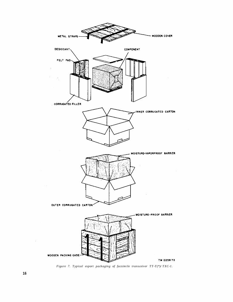
Figure 7. Typical export packaging of facsimile transceiver TT-T(*)/TXC-1.
16

TM 2258-42
TM 2258-74
Figure 8. Drum chock in place on facsimile transceiver.
Figure 9. Location of tubes, facsimile transceiver TT-1(*)/TXC-1.
17

TM 2258-75
Figure 10. Location of tubes, rectifier power unitPP-86(*)/TXC-1.
(3) Connect the ac plug on the exhaustblower power cord to the 115-volt,3-ampere outlet on the chassis of therectifier power unit.
Caution: When replacing fuses, make surenot to use them in a circuit with a currentrating above the specified value of the fuse.
c. Terminal Panel (fig. 144). The terminalpanel located on the right end of the facsimiletransceiver is used for connecting the facsimileequipment to the communication circuit.
(1)
(2)
(3)
18
PHONES jack (J1) (figs. 141 and 168).This is a two-circuit jack that receives atype PJ-055B plug. It is connectedthrough a resistor attenuation networkto the primary of T7, the audio-frequency(af) input matching transformer (1:1ratio) used for coupling between the lineand the transceiver. It may be used formonitoring the line.RADIO RCVR jack (J2). This is a two-circuit jack wired in parallel with thePHONES jack, and may be used with atype PJ-055B plug as an input connec-tion to the transceiver.LINE binding posts. These posts serveas input and output connections for thetransceiver. When the selector switch isin either the RECORD PHOTO orRECORD DIRECT position, the LINEposts are connected to the primary of
(4)
(5)
(6)
(7)
input transformer T7. The center bind-ing post, marked REC C T (fig. 168),connects directly to the center tap of theprimary of T7 at all times. When theselector switch is in TRANSMIT posi-tion, and the DB METER indication is+2 decibels (db), the two outside LINEbinding posts are connected through 300-ohm resistors from secondary No. 2 ofoutput transformer T2. They will fur-nish the standard 0 decibel referred to 1milliwatt in 600 ohms (dbm) signal (.78volt to a 600-ohm load) for connectionto commercial wire lines.CARBON MIKE jack (J4). This is athree-circuit jack. It is an output con-nection that receives a type PJ-068 plug,commonly furnished with carbon micro-phones and is connected to one-half ofsecondary No. 2 of output transformerT2. When the selector switch is onTRANSMIT, secondary No. 2 of trans-former T2 is connected to the LINEbinding posts.RADIO XMTR jack (J3). This is a jackconnected in parallel with the CARBONMIKE jack. It is used as a transceiveroutput, connection to the radio transmit-ting circuit. The output level is .4 voltinto a 100-ohm load.LINE JACK (J5). This two-circuit po-larized jack requires a special plug. Itserves as the high-level input and outputconnector for the transceiver. Thepolarized plug of the UC coupling coilfits this jack. When the selector switchis set at TRANSMIT, the LINE JACKis connected across secondary No. 1 ofoutput transformer T2, and provides anoutput of 15.15 volts into a 600-ohm line(+26 dbm). One side of the LINEJACK, labeled GND, is always at groundpotential and is connected to the trans-ceiver frame. When the selector switch isset at RECORD PHOTO or RECORDDIRECT, the LINE JACK is con-nected to the secondary of transceiverinput transformer T7.MOTOR JACK (J6). This three-circuitjack receives a type plug that permitsbreaking into the 1,800-cycle signal cir-cuit, between the motor amplifier bufferstage of the fork oscillator unit and the

motor amplifier driver stage of the trans-ceiver for test purposes or for supplyingan external signal to the motor amplifier.The drum of Facsimile TransceiversTT-1D/TXC-1, TT-1E/TXC-1, andTT-1F/TXC-1 can be operated at anyspeed from 30 revolutions per minute(rpm) to approximately 100 rpm byconnecting an external signal of approx-imately 26 to 35 volts root mean square(rms), with a source impedance of 20,000ohms or less, to the sleeve and ring of aplug and inserting it into MOTOR JACKJ6. It may be necessary to ground theexternal generator to Facsimile Trans-ceiver TT-1D/TXC-1, TT-1E/TXC-1,or TT-1F/TXC-1 for satisfactory op-eration of the motor circuit. The motorspeed control switch, S4 (30 to 60 rpm),should be in the 60RPM position forexternal signal frequencies above 1,200cps, and in the 30RPM position for fre-quencies below 1,200 cps.
(8) ( ND post. Directly below the LINEbinding posts is a GND post connectedto the frame of the transceiver.
d. Mounting Dust Removal Blower Unit. Placethe dust removal blower unit on the right-handend of the shelf of Table MT-252(*)/TXC-1 asshown in figure 2. Be sure that the blower unitis resting firmly on the shelf and against the crossbrace before tightening the thumbscrews locatedon the channels. Remove the canister by loosen-ing. the swivel thumbscrew. Remove the paperbag from the canister and put activated carbon inthe space between the inner and outer tubes.Shake the canister well to pack the carbon downand fill to within one-half inch of the top. Replacethe paper bag in the canister, making sure thatthe flange projection lies uniformly along the topsurface. Spread the paper bag so that it staysclose to the inside of the inner tube. Replace thecanister by sliding it into and around the threenuts used as guides. Tighten the swivel thumb-screw until the canister is held firmly in place.Do not overtighten the thumbscrew since it willtend to distort the assembly. Clamp the flexiblehose to the exhaust tube with one of the hoseclamps provided and secure tightly. Slide thefree end of the flexible hose through the slot in thetable and clamp it to the blower unit with theother hose clamp.
15. Connections to Wire Lines
Several distances can be obtained over voicewire line circuits for a given line loss. The max-imum distance that can be covered for a givenline loss generally depends on the type of wire linefacility used. The wire circuits used to transmitfacsimile signals must be of better quality thanthose suitable for voice transmission. The methodof connection used depends on the. type of circuit,the loss and faults in the circuit, type of terminalequipment used, and the frequency characteristicsof the line.
a. The facsimile signal delivered by FacsimileTransceiver TT-1(*)/TXC-1 is an am 1,800-cpscarrier, and the circuit used is capable of passingboth the upper and lower sideband frequencies,900 to 2,700 cps, as flat as possible for satisfactoryreproduction. The impedances of all the circuitsalong the line should be matched to avoid re-flections. When the circuit distance is long, thereceived signal is reflected back to the sendingstation and is reflected again over the line to thereceiving station. This causes two images toappear on the received copy. Echo suppressors,which allow transmission in only one direction,may be used in the circuit to overcome these effects.On short high-speed circuits, the echoes produceno undesirable effects.
b. It is important that the signal level at thereceiving station be constant, especially whenreceiving photographic copy, since instantaneouschanges as small as ¼ db in signal level will causea noticeable change in the shading of the recordedpicture. However, an increase or decrease of 1to 2 db is permissible if the change occurs gradu-ally during the transmission of an entire picture.
c. Delay in the line will cause different fre-quency components of the facsimile signal to bedisplaced. This results in a distorted picture.Delay correcting networks may be used to equalizefrequency transmission rates. A high signal tonoise ratio is desirable to eliminate dark streaks(noise) or spots on the recording.
d. Transmitting signal levels are explained in(1) through (4) below.
(1) A +26 dbm output signal (0 dbm=1 mil-liwatt (mw) in 600-ohms), approximately15 volts, is available at LINE JACK J5for transmission of facsimile signals oversingle field wire circuits made up of WireW-110-B or WD-1/TT. The line mustbe long enough to attenuate the signal
19

(2)
(3)
(4)
20
down to -10 dbm or lower to preventoverloading the receiving transceiver.If more than one circuit is brought intothe same terminal controlling the trans-mission of facsimile signals, cross talktests should be made before operation ofthe facsimile circuit is begun with +26dbm going into the line.Transmission over open-wire telegraphlines is sometimes practical, withoutdanger of cross talk into dispatcher cir-cuits, with a +26 dbm signal going intothe line. As a further precaution againstcross talk in this type circuit, transposi-tion of the wires at ¼-, ½-, or 2/3-mileintervals would be advantageous.A line that has low-loss characteristicsmay furnish a received signal which ishigher than the LINE binding post inputof the transceiver can accept for satis-factory reproduction. This is indicatedby the necessity of setting the GAINcontrol near zero to obtain the standard+2 db indication required for properoperation of the transceiver. When thiscondition is encountered, for receivingonly, connect the line to a plug and insertthe plug into the jack on the transceivermarked RADIO RCVR. To reducehum, connect a wire from the GND ter-minal to the REC CT terminal. Leavethe plug out of the RADIO RCVR jackexcept when receiving copy. When trans-mitting, the line must be reconnected tothe LINE terminals.
For transmission over a single commercialwire line, the standard 0 dbm (.78 volt)signal is available at the LINE terminalson Facsimile Transceiver TT-1(*)/TXC-1 when the GAIN control (figs. 13through 16) on the front, panel is adjustedfor a reading of +2 db on the DBMETER.
Caution: When operating into AT&T(American Telephone and TelegraphCo.) lines (fig. 11), do not apply morethan 0 dbm to the line since these circuitsare adjusted for proper operation forinputs at this level. To limit the signalapplied to their lines, AT&T requiresthat a 104A or 105A coupling coil beconnected between the facsimile equip-ment and the line. These coils limit the
amount of signal voltage that can be ap-plied to the line and, in effect, place aheavy load across the line when the inputsignal goes above 0 dbm.
(a)
(b)
(c)
If more than one commercial line isbeing supplied by Facsimile Trans-ceiver TT-1(*)TXC-1, the outputlevel at the LINE terminals will dropdown below 0 dbm.If only two lines are being fed, the out-put at the LINE terminals can bebrought up to 0 dbm by shunting re-sistors R84 and R85 (fig. 169) (inseries with the LINE terminals) with300-ohm resistors.
If more than two lines are being fed,the output at the LINE terminals maybe brought up to 0 dbm by shuntingR84 and R85 with resistors that havea lower value than 300 ohms. Ineither case, the final adjustment shouldbe reached with a DB METER readingof +2 db.Note. If a DB METER is not available for
measuring the input at the coupling coils,temporary connections can be made to theDB METER in Facsimile Transceiver TT-1(*)/TXC-1. The regular connections to themeter must be removed after setting theGAIN control for a normal output readingof +2 db on the DB METER. Eight dbmust he added to the meter reading whenmeasuring the signal voltage present across thecoupling coil because the DB METER inFacsimile Transceivcr TT-1(*)/TXC-1 is cali-brated at the old reference level of 6 mw into a600-ohm line. For 0 dbm at the coupling coil,the meter therefore will read -8 db. Ifmeasuring with a vacuum-tube voltmeter, thecorrect reading is .78 volt.
e. Use of UC Coupling Coil (fig. 6). When in-ductive coupling to a telephone line is required,use the UC coupling coil furnished with FacsimileSet AN/TXC-1(*) except with Facsimile SetAN/TXC-1D. This coupling (feed) coil is de-signed to fit over the receiver of the handset usedon Telephone EE-8 and other telephone handsets(fig. 12). The coil is fitted into place and theplug at the end of the cord from the UC couplingcoil is connected to the polarized LINE JACK(J5) on the transceiver terminal strip. Approxi-mately 30 db is lost when using this method ofconnection. When using a line of Wire W-110-Bor WD-1/TT between transceivers, if there signalvoltage is required than that obtained by using

TM 2258-79
Figure 11. Facsimile installation, private line antisidetone station connectors.
the magnetic coupling connector on the UCcoupling coil, connect the telephone line directlyto the 1V connector on the coupling coil. If thecircuit loss is exceptionally high, the connectormarked 6V on the coupling coil may be used,provided, the line loss is at least 18 dbm beforereaching the first telephone exchange or repeater.
Warning: Do not use the coupling coil outputsmarked 1V or 6V with any commercial or com-mon battery circuits, or any circuit that uses sig-naling or ringing.
16. Talking Circuits
Facsimile Transceivers TT-1A/TXC-1 throughTT-1F/TXC-1 have built-in talk-back circuitfacilities and permit communication betweentransmitting and receiving operators over thesame circuit used for facsimile signals. Thisfacility is controlled by the STANDBY-MON-TALK switch (S5) on the front panel. However,
when using Facsimile Transceiver TT-1/TXC-1,external telephones must be used at each end ofthe circuit. Facsimile operation is also possibleover blind circuits, on prearranged schedules,without voice communication.
17. Radio Circuit Considerations
a. Subcarrier Amplitude Modulation (SCAM).The average amplitude variations of the facsimilesignal change in proportion to the average densi-ties of the picture being scanned. Slight ampli-tude variations in the received signal, other thanthose caused by the components of the facsimilesignal, also will cause objectionable distortion inthe received copy. This is especially noticeablewhen receiving photographic material. Whentransmitting black and white copy only, consider-able changes in amplitude can be tolerated, al-though distortion, caused by amplitude varia-tions in the received signal, will appear in the
2 1

Figure 12. UC coupling coil attached to telephone headsets.
Copy.(1)
(2)
(3)
form of inconsistent lineweights throughout the
For hf transmission (below 40 mc), theeffects of fading must be taken into con-sideration. If transmission is by groundwave only, over short distances, circuitscan be established for satisfactory re-production of both photographic andblack and white copy by utilization ofsuitable transmitting power levels. Thechannel bandwidth must be sufficient topass the full frequency range (both upperand lower sidebands, 900 to 2,700 cps)produced by the facsimile transceiver.When transmission is by both ground andsky wave, the effects of fading mustagain be taken into consideration. Trans-mitted picture elements arriving at thereceiving station, via the ground wave,may be out of phase with the samepicture element arriving via the skywave. This causes a change in the in-stantaneous signal level and consequentdeterioration of the received copy.Compensation may be made to reducethe effects of fading by reducing thespeed of transmission. Facilities forhalf-speed operation are provided onFacsimile Transceivers TT-1D/TXC-1,TT-1E/TXC-1, and TT-1F/TXC-1 byreducing the speed of rotation of thescanning drum from 60 rpm to 30 rpm.
b. Subcarrier Frequency Modulation (SCFM).Both photographic and black and white copy can
22
be transmitted over regular very-high-frequency(vhf) or ultra-high-frequency (uhf) fm radio cir-cuits by merely connecting Facsimile TransceiverTT-1(*)/TXC-1 to the input and output termi-nals of the radio equipment. The received signalsmust be of sufficient strength to keep the limitercircuits of the fm receiver saturated at all times.Details for this type connection using ConverterCV-2C/TX are given in paragraph 60.
c. Frequency-Shift Transmission. To eliminatethe effects of signal fading and to reduce the effectsof interference and noise, a frequency-shift circuitusing a regular cw transmitter is used. In thissystem, the amplitude variations of the facsimilesignals are converted into frequency variations,and the facsimile signal components are trans-mitted over a regular cw radio channel as propor-tional shifts in frequency rather than changes inamplitude. At the receiver, a crystal-controlledoscillator is heterodyned with the incoming fre-quency-shift signals to produce corresponding afvariations, and an af discriminator is used toconvert the signal into the amplitude variationsrequired for operation of Facsimile TransceiverTT-1(*)/TXC-1. Details for this type connec-tion using Converter CV-2C/TX and ExciterUnit O-5B/FR are given in paragraph 61.
18. Connections to Radio CircuitsWhen Facsimile Transceiver TT-1(*)/TXC-1
is to operate in a conventional am radio transmit-ting and receiving circuit (SCAM), make connec-tions as follows:
a. Plug one end of Cord CD-1018 into thetransceiver RADIO RCVR jack (J2). Plug the

other end into the phones output jack of the radioreceiver. This is the receiving connection.
b. Plug one end of Cord CD-1019 into theRADIO XMTR jack (J3) on the transceiver.Plug the other end into the microphone jack ofthe radio transmitter. This is the transmittingconnection.
c. Plug the radio carbon microphone into theCARBON MIKE jack (J4) of the transceiver.
d. Plug the radio headset into the PHONESjack (J1) on the transceiver. The radio transmit-ter and receiver may be operated normally forradio voice communication while the transceiverselector switch is set at either the SET RANGE orSTANDBY position.
e. If the radio receiver output is too low for thetransceiver, check the label on the small circulartag screwed to the terminal board between theRADIO RCVR and PHONES jack. Ordinarily,the tag will read 2,500 ohms (this indicates theimpedance at which the transceiver input circuitis set to match the phones circuit output of theconventional radio receiver). Some radio receivercircuits have a 250-ohm output. Connection of a250-ohm receiver output to the 2,500-ohm trans-ceiver input will be indicated by a failure to get asufficiently high reading on the transceiver DBMETER, even though the transceiver GAINcontrol (R59, R60) may be set at maximum andthe monitored signal may sound loud in the head-set plugged into the PHONES jack. To changethe transceiver input to match a 250-ohm receiveroutput circuit, proceed as follows:
(1) Remove the back cover of the trans-
(2)
(3)(4)
ceiver to gain access to the terminalboard mounted inside the transceiver onthe metal brace near the DB METER.Connect a wire between terminals 1 and2 of the terminal board to short-circuitresistor R79 (fig. 168).Remove the wire which is soldered toterminal 3, and solder it to terminal 4.This places resistor R82 in the circuit.Replace the transceiver rear cover.Remove the two screws that hold theround tag in place on the outside terminalboard. Turn the tag over so that theexposed side reads 250 ohms. Replacethe screws.
Note. To avoid pick-up while receiving, itmay be necessary to connect the GNI) bindingpost to one of the LINE binding posts or to theREC C T binding post. Remove this connec-tion when transmitting.
f. If the facsimile transceiver output is too highfor the radio transmitter input circuit, reduce thegain of the radio transmitter preamplifier. Atemporary alternative, for example, is to set upthe facsimile transceiver in the normal manner,then reduce its maximum output by turning theGAIN control until the maximum meter reading is-4 db.
19. Darkroom Installation
When Facsimile Set AN/TXC-1(*) is used forphotographic reception of copy, install the equip-ment in a large, well-ventilated darkroom fromwhich all light is excluded. A large sink and run-ning water are necessary.
a. Safelight. Install a safelight equipped witha Wratten series OA filter, or its equivalent.This gives a yellowish green light. Locate thelight approximately 5 feet from both the trans-ceiver and the sink.
b. Additional Equipment. In addition to Pho-tographic Equipment PH-549/TXC-1 which issupplied with Facsimile Set AN/TXC-1(*), thefollowing equipment is desirable:
1 electric print dryer.1 gross each of contact printing paper, single
weight, 12 inches by 18¾ inches, contrastF1, F2, F3, and F4, Eastman Kodak orequal.
2 dozen each, contact printing paper, contrastF0 and F5.
1 contact printer, 18 inches by 22 inches.1 darkroom clock with sweep second hand.1 squeegee, 10 inches long.2 or more ferrotype plates, chrome, to fit
electric dryer.2 print tongs.
20. Service upon Receipt of Used orReconditioned Equipment
a. Follow the instructions in paragraph 13 foruncrating, unpacking, and checking the equip-ment.
b. Check equipment for tags or other indicationspertaining to modifications (par. 11) or otherchanges. If any changes in the wiring (other thanthe modifications listed in paragraph 11) havebeen made, note the change on the schematicdiagram in this manual.
c. Check and lubricate the equipment as in-structed in paragraphs 44 through 47.
d. Perform the installation and connection pro-cedures outlined in this section.
23

Section Il. CONTROLS
21. GeneralAll electrical operating controls of Facsimile
Set AN/TXC-1(*) are located on the sloping frontpanel of Facsimile Transceiver TT-1(*)/TXC-1(figs, 13, 14 and 16). Two mechanical controls,the drum-engaging lever, and the clamp-bar con-trol knob are located on the drum and its controlmechanism. Controls are the same for all fac-simile transceivers, except for minor differences
AND INSTRUMENTS
required by changes in the talk-back circuit, thedrum speed circuit, and the starting and phasingcircuits on certain models. Input and outputconnections are located on the right-hand end ofthe transceiver.
22. Controls and Their UsesThe following chart lists the controls of Fac-
simile Transceiver AN/TXC-1(*) and indicatestheir functions.
a. Panel Controls.
Function
Power ON-OFF switch (S2) --------------
STANDBY-MON-TALK switch (S5) (Notincluded in Facsimile Transceiver TT-1/TXC-1).
Selector switch (S1)---------------------
Makes and breaks one side of the 110-volt, 60-cycle ac line circuit whichfeeds the primary of transformer T11, located in Rectifier Power UnitPP-86(*)/TXC-1. In the ON position, plate, filament, and screenvoltages are applied to all tubes in the facsimile set. Power is madeavailable for starting and operating the synchronous motor, subject tochanges made by the selector switch (S1) and STANDBY-MON-TALKswitch (S5).
In the STANDBY (upper) position, it connects the loudspeaker in thecircuit and permits the operator to monitor the communication channel.If both the STANDBY-MON-TALK switch (S5) and the selectorswitch (S1) are in the STANDBY positions, the synchronous motor willnot operate. This position is used to receive voice communicationswhen it is not necessary to have the motor running.
Warning: When using Facsimile Transceivers TT-1B/TXC-1through TT-1F/TXC-1, the motor may run at a nonsynchronous speedin any switch position. When the motor is running at synchronousspeed, the drum will revolve ½ or 1 revolution each second, and therespective 900- or 1,800-cycle audible tones will be heard coming fromthe motor laminations.
In the MON (middle) position, it connects the loudspeaker and permitsthe operator to monitor the communication channel. The motor issupplied power and may be started and run at synchronous speed.This is the normal position for receiving voice communications whenphasing the transmitting and receiving equipments preparatory tosending and receiving facsimile copy.
In the TALK (lower) position, the loudspeaker becomes the microphoneof a voice intercommunication system. The switch must be held in theTALK position; if pressure is released, it will snap back to the MONposition. The TALK position is used when talking to the facsimileoperator on the other end of the circuit.
Note. The talk-back circuit operates only when the selector switch (S1) is at STANDBY.
Caution: The talk-back circuit will not function over a radio circuitthat uses Converter CV-2C/TX, TM 11-2252A, unless the converteris bypassed for voice communication.
This control determines the function of the transceiver. Positions andfunctions are as follows:
Position Function
T R A N S M I T - - - - - The facsimile transmitting circuit is estab-lished. Impulses representing elements ofthe facsimile copy are sent out over thefacsimile circuit to the receiver. This is thenormal operating position when the trans-ceiver is actually transmitting copy. Inthis position, the switch also closes the radiotransmitter relay circuit associated withCARBON MIKE jack J4.
24

Control
Selector switch (S1)-Continued
START button (S4) (Facsimile Trans-ce ivers TT-1 /TXC-1, TT-1A/TXC-1,TT-1B/TXC-1, TT-1C/TXC-1 and TT-1D/TXC-1 only).
PHASE button (S3) (Facsimile Trans-ce ivers TT-1 /TXC-1, TT-1A/TXC-1,TT-1B/TXC-1, TT-1C/TXC-1 and TT-1D/TXC-1 only).
START-PHASE switch (S3) (FacsimileTransceivers TT-1D/TXC-1, TT-1E/TXC-1, and TT-1F/TXC-1 only).
Function
SET RANGE The transmitting circuit is established butimpulses are not sent over the line.
This position is used when the operator isengaged in setting the contrast range (wedge)for transmitting a specific piece of copy.
Note. Since the transceiver is disconnected from the linewhen the selector switch is at SET RANGE, some methodmust be used to avoids disconnect when operating with acommercial line. A telephone set across the line or a specialtelephone key will hold the line (fig. 11). A dry line, onenot normally used with signaling, will not be rung off.
STANDAY. . . . . . . . . . . . The tubes are kept ready for operation of thetransceiver. This is the normal setting
RECORD PHOTO...
RECORD DIRECT.
during the periods when copy is not actuallybeing transmitted or received.
. . The receiving circuit is established to use therecorder lamp, which causes recording ofreceived copy on photographic paper. Thisswitch position is, used to set the gain andphase the receiving transceiver. A raisedportion of the selector switch name plateenables the operator to set the switch atRECORD PHOTO in the darkroom.
. The receiving circuit is established to use thestylus instead of the recording lamp. Thestylus causes recording of received copy ondirect recording paper or other electro-sensitive paper. Moving the selector switchto RECORD DIRECT position mechani-tally moves the stylus into contact with thepaper on the drum.
Note. In the TRANSMIT, RECORD PHOTO, andRECORD DIRECT positions, automatic end-of-copystop relay K1 remains energized if limit switch S8 hasbeen thrown. It is necessary to switch to STANDBY orSET RANGE to reenergize relay K1 in Facsimile Trans-ceiver TT-1F/TXC-1.
This is a nonlocking, multipole, push-button switch. When pressed, thisbutton momentarily applies power to the start winding of the motorand the motor is operated above its normal operating speed. When theSTART button is released, the motor slows down to its normal operatingspeed and continues to operate at that speed.
Caution: The motor of Facsimile Transceiver TT-1B/TXC-1 orTT-1C/TCX-1 is at synchronous speed only when the 1,800-cycle tonecan be heard from the motor laminations.
This is a nonlocking, multipole, push-button switch. The receiving oper-ator presses this button to energize the phasing circuit of the receivingtransceiver, while the transmitting operator is sending phasing pulses.The operation assures that both transmitting and receiving drums arein the same position at the same instant. Once the relatively shortphasing operation is completed, the machines will remain synchronizedbecause both drums are driven by motors running at the same speed.
In Facsimile Transceivers TT-1D/TXC-1, TT-1E/TXC-1, and TT-1F/TXC-1, the functions of the START switch (S4 in previous models)and the PHASE switch (S3 in previous models) have beeh combined intoone, which is START-PHASE switch S3 (fig. 15). It is a three-position,nonlocking, lever-type switch which is spring-loaded to return to neutralwhen released from the START or PHASE position. The operatorthrows the START-PHASE switch to the START position momen-tarily to apply power to the start winding to bring the motor above thenormal operating speed. When switch S3 is released, the 1,800 cps is
25

Control Function
START-PHASE, switch (S3) (FacsimileTransceivers TT-1D/TXC-1, TT-1E/T X C - 1 , a n d T T - 1 F . T X C - 1 O n l y ) -Continued
30RPM-60RPM (motor speed control)switch (S4) (fig. 138) (Facsimile Trans-ceivers TT-1D/TXC-1, TT-1E/TXC-1,and TT-1F/TXC-1 only).
CONTRAST control (R45) - - - - - - - - - - - -
G A I N c o n t r o l ( R 5 9 a n d R 6 0 ) . . .
DB METER (M1) . . . . . . . . . . . . . . . . . . . . .
MOTOR ON-MOTOR OFF switch. (Addedon Facsimile Transceiver TT-1/TXC-1only by MWO SIG 11-2258-1).
SPEAKER jack. (Added on FacsimileTransceiver TT-1/TXC-1 by MWO SIG11–2258–1).
RB meter (M3) (fig. 138). . . . . .MOTOR CURRENT meter (M2) -- ----
applied to the synchronous winding of the motor causing the motor tolock in at its normal operating speed. The receiving operator throwsthe START-PHASE switch to the PHASE position to energize thephasing circuit of the receiving transceiver while the transmitting oper-ator is sending phase pulses. When the relatively short phasing opera-tion is completed, the machines remain Synchronized because bothdrums are driven by motors running at the same speed.
Caution: The motor of Facsimile Transceiver TT-1D/TXC-1,TT-1E/TXC-1, or TT-1F/TXC-1 is at synchronous speed only whenthe 1,800-cycle tone can be heard from the motor laminations.
Used in the 30RPM position to provide half-speed operation of the record-ing drum when transmitting over long radio circuits under adverse re-ceiving conditions, and in the 60RPM position for normal operation.
A calibrated potentiometer which adjusts the contrast range (differencebetween minimum and maximum signal level of the transmitted signal)by adjusting the magnitude of currents in the photocell bridge circuit.This control is operated only by the transmitting operator, althoughthe setting he makes is determined partially by the request of the re-ceiving operator. The dial on this control is numbered from 1 to 100,and the ranges for transmitting positive and negative are indicated.
A dual potentiometer which serves to control the level of the signal han-dled by the transceiver. It does not change the contrast range.
The front panel DB METER serves as a guide in setting GAIN andCONTRAST controls. It is calibrated in db with reference to 0 powerlevel of 6 mw in 600 ohms. Line power levels are commonly expressedin terms of dbm, decibels with reference to 0 power level of 1 mw in 600ohms. The DB METER on this equipment does not register the trueline signal level in either db or dbm. When the facsimile transceiverselector switch is at TRANSMIT and the DB METER indicates plus2 db, the resultant power dissipated in a 600-ohm resistive load con-nected across the LINE binding posts is 1 mw (.78 volt), representingthe standard 0 dbm reference. When the facsimile transceiver is re-ceiving, there is no fixed relationship between line power and db powerand DB METER reading, because meter readings depend on the settingof the GAIN control. In paragraph 5, input and output signal levelsfor the transceiver are expressed in true line dbm. Elsewhere in thismanual, however, the term db is used merely to express the relativelevel readings of the DB METER, not to indicate line levels in dbm.
Used for setting the transmitting contrast (wedge) range.This meter may be temporarily disconnected from the circuit, and may be
used to measure dbm (at 0 dbm =1 mw into 600 ohms) directly, provid-ing 8 db is added to the meter reading when so used.
Provides a means for turning off the motor when the selector switch is inthe STANDBY position.
Permits connecting an xternal loudspeak to the transceiver so that themaximum and minimum signals for setting contrast will be audible tothe receiving operator.
Provides continuous check on regulated 250-volt supply.Connected in series with motor voltage supply for setting proper motor
current.Note. Meters M2 and M3 were added to Facsimile Transceivers TT-1/TXC-1 and TT-1A/
TXC-1 by MWO SIG 11-2258-2.
26

Figure 13. Controls, facsimile transceiver TT-1/TXC-1.
Figure 14. Controls, facsimile transceiver TT-1A/TXC-1 through TT-1C/TXC-1.
27

Figure 15. Controls, facsimile transceiver TT-1D/TXC-1 and TT-1E/TXC-1.
b. Drum Controls. Two mechanical controlsare located on the drum mechanism.
(1) The clamp bar control knob (fig. 17) islocated on the right side of the rotatingdrum. It is used to open and shut theclamps that hold copy to the drum andcan be operated only when the motor isnot running and the drum is not rotating.This knob has three positions:
(a)
(b)
(c)
(2)
28
Center position (both sides of the clampsare fastened). This is the normaloperating position when copy or record-ing paper is securely fastened to thedrum during either transmitting orreceiving.
Counterclockwise position (clamp is openon the side toward the operator). Theclamping bar is at the top of the drum.This position is used only momentarily,while inserting copy and preparing tofasten it to the drum.
Clockwise position (clamp is open on theside away from the operator). Theclamping bar is at the top of the drum.This position also is used only momen-tarily, while fastening copy to thedrum.
The drum engaging lever (fig. 16) islocated on the left side of the drum.It is used to engage the half nuts on therotating drum with the lead screw,
causing the drum to travel from right toleft during the scanning process. Thisposition is used during the actual trans-mitting or receiving of copy. When thelever is pushed away from the operator,it disengages the drum from the leadscrew so that the drum rotates but doesnot travel from right to left. The dis-engaged position is used at all timeswhen copy is not actually being trans-mitted or received.
Warning: On Facsimile TransceiversTT-1/TXC-1 and TT-1A/TXC-1, theguide arm of the engaging mechanismmay leave its track on the chassis of thetransceiver if the drum is pushed to thefar left with the protective housingremoved from the motor and clutch.If this occurs, the drum will not feedproperly on the lead screw. In FacsimileTransceivers TT-1B/TXC-1 and TT-1C/TXC-1, a machine screw providesa stop to prevent the guide arm fromleaving the track.
c. End-of-copy Limit Switch (S8). A pressure-sensitive switch is mounted on the left-handbearing block of Facsimile Transceiver TT-1F/TXC-1 (fig. 16). The drum, in its extreme left-hand excursion, will actuate this switch. Thiscauses power to be removed from the synchronousdrive motor and the amplified facsimile signal will

Figure 16. Controls, facsimile transceiver TT-1F/TXC-1.
be diverted to ground. It is therefore not neces- supplied with Facsimile Set AN/TXC-1D. Thissary for the operator to be with the equipment switch is located on the blower and canister sup-at the end of a transmission. porting bracket (fig. 2) and should be thrown to
d. Blower Switch (S9). A toggle ON-OFF the ON position only when the equipment is usedswitch is provided for the dust removal blower for direct recording.
Section Ill. OPERATION UNDER USUAL CONDITIONS
Note. The operating instructions in this section are based on the use of a voice communication circuit betweentransmitting and receiving operators. Blind circuits, however, in which transmission and reception of facsimile copy arecompleted on prearranged schedules, are feasible without voice communication. Experienced operators will find numeroussatisfactory ways of saving time by varying the operating procedures described in this section.
23. PreparationsBefore operating Facsimile Set AN/TXC-1(*),
determine the type of circuit being used, wire orradio, and all types of transmission and receptiondesired; this will affect the operating procedure.
a. Index of Cooperation. Transmitting andreceiving equipments at each end of the circuitshould have the same index of cooperation, thesame speed, and a recording system responsive tothe modulated signal of the transmitter. Theindex of cooperation is equal to the scanning drumdiameter times the pitch (lines per inch scanned);thus, the index of cooperation of FacsimileTransceiver TT-1(*)/TXC-1 is equal to 6 (drumdiameter in inches) 96 (lines per inch) = 576.
Satisfactory operation may be obtained eventhough the indexes of cooperation are not exactlythe same. Differences of as much as 5 or 10 per-cent are generally not noticeable in photographicor message copy. The indexes of cooperationmay differ by as much as 50 percent for weathermap work or other line illustrations withoutaffecting the usability of the received copy. Themaximum speed tolerance between the trans-mitting and receiving scanning drums of FacsimileTransceivers TT-1(*)/TXC-1 is .00033 percent.The table below lists the standards applicable inpresent day military and commercial wire andradiophoto facsimile circuits.
29

Standard Index Speed(rpm)
Facsimile Transceiver TT-1(*)/TXC-1 . .. 576 60Facsimile Transceiver FX-1-( ) . . . . . . . . . 264 90Acme .... . . . . . . . . . . . . . . . .. 290 100Associated Press . . . . . . . . . . . . . . . . . . . . . . . . 380 100CCIT and CCIR (Consultive Committee
on International Telegraph and Consul-tive Committee on International Radio). 264 90
CCIT and CCIR . . . . . . . . . . . . . . . .. . . . 352 60International News Service . . . . . . . . . . . . . 264 90Western Union . . . . . . . . . . . . . . . . . . . . . . 254 180
b. Circuits.(1)
(2)
If a wire circuit is used between a trans-mitting transceiver and a receiving trans-ceiver, be certain that connections arecorrect for the quality of line (par. 15).If a radio circuit is used, and ConverterCV-2C/TX is in the circuit betweenfacsimile transceiver and radio transmit-ter, the transceiver talk-back circuit willnot function.
c. Type of Transmission. Adjustment of thetransmitting transceiver will depend on the typeof transmission being made and the type of re-ceiving process in use. Coordination is necessarybetween transmitting and receiving operators.Transmission can be either positive or negative.In positive transmission, black portions of thecopy are transmitted as high-level signals whichprint at the receiving end as black (fig. 21). Innegative transmissions, white portions of the copyare transmitted as high-level signals which printon the negative (fig. 21). The relative signallevels are indicated by the DB METER on thetransceiver. The kind of copy being sent and theuse to be made of the copy at the receiving enddetermine whether transmissions should be nega-tive or positive.
d. Type of Reception.(1)
(2)
30
Direct recording. When the time elementis important, use the direct recordingmethod. Slight loss of detail and fidelityof half tones (shades of gray betweenwhite and black) must be tolerated. Copyreceived on Teledeltos or Timefax NDApaper is ready for immediate use; copyreceived on Time fax A paper permitsmaking duplicates by the gelatin padmethod (par. 29) in a very short time.Positive photographic recording. Whenonly one copy is needed and when finer
24.a.
(3)
detail and better half-tone reproductionthan that obtained by direct recordingare necessary, use the positive photo-graphic recording method. Copy re-ceived by this method requires photo-graphic processing before it can be used.Negative photographic recording. Whenmaximum quality of a photograph isrequired, use the negative photographicrecording method. Copy received bythis method requires photographic proc-essing and positive prints can be madefrom the negative.
Preliminary Transmitting OperationsInitial Operation.(1) Cut the copy to be transmitted to a size
(2)
(3)
(4)
no larger than 12 by 18 5/8 inches. Keepthe actual message for transmission to 12x 17½ inches for both photographic anddirect recording.Fasten captions on the copy to be trans-mitted with scotch tape or write themon the copy with either ink or pencil.Throw the power ON-OFF switch of thetransceiver to the ON position. Turnthe selector switch to the SET RANGEposition. Wait for the high-pitched1,800-cycle tone. (There is no audibletone when the selector switch is inSTANDBY position and the STAND-BY-MON-TALK switch is in theSTANDBY position.) Normally, a 10-minute warm-up period should be allowedbefore transmitting. The dust removalblower ON-OFF switch should be in OFFposition when the equipment is in use asa transmitter.Press backward on the engaging lever,on the left end of the drum mechanism,to disengage the drum from the leadscrew. Push the drum to the right-handend of the lead screw. Turn the drumso the clamping bar is on top.
b. Placing Copy on Drum (fig. 17).(1) Raise one edge of the clamp bar by turn-
ing the knob on the right end of the drumto its clockwise position. Place thelower edge of the copy, face up, underthe rear edge of the clamp bar. Turnthe knob to its counterclockwise positionto set the clamp and open its other edge.Revolve the drum, wrapping the copy

(2)
Figure 17. Loading drum with direct recording paper.
around it. Insert the loose edge of the 2258-6 and on Facsimile Transceivercopy under the clamp. Pull the copy TT-1F/TXC-1.tightly around the drum with a wiping b. Setting GAIN and CONTRAST controls.motion of the hand. Set the clamp by (1)turning the clamping bar knob backto its center position.Make certain that there are no bulgesin the copy. If the copy is too small tofit around the drum and into the clamp-ing bar, fasten it to the drum withscotch tape.
25. Transmitting Positive for Direct Recording (2)In transmitting positive for reception on Tele-
deltos, Timefax NDA, or Timefax A paper,proceed as follows:
a. Preparations.(1) Allow the transceiver to warm up. Load
the drum as outlined in paragraph 24. (3)(2) Be sure the selector switch is on the SET
RANGE position. Place the dust re- (4)moval blower switch in the OFF positionon equipment modified by MWO 11-
Place the whitest portion of the copy inline with the scanning beam. Set theGAIN control at 65. Adjust the CON-TRAST control until the meter indicatesa minimum. Check the meter readingand move the drum slightly backwardand forward while examining a differentwhite portion of the copy to be sure thewhitest spot is used.Move the drum so that the blackestportion of the copy is illuminated bythe spot of light. Be sure the blackestportion actually is used by again rotatingthe drum slightly backward and forwardwhile checking the meter.Adjust the GAIN control so that themeter indicates +2 db.Return to the whitest portion of the copyand readjust the CONTRAST controlfor a minimum reading on the meter.
31

(5)
(6)
(7)
32
Repeat the procedures in (2), (3), and (8)(4) above until the final adjustments ofGAIN and CONTRAST controls givemeter readings differing by at least 15db between the blackest and whitestportions of the copy. The maximumreading (on black copy) should notexceed +2 db.If the UC coupling coil is used to couplethe transceiver output to a telephonecircuit, an additional adjustment must bemade at this point. With a +2 db meterreading, indicating maximum trans-mitted signal, turn the selector switch tothe TRANSMIT position. Listen closelyin the telephone earpiece, and slowlyrotate the coupling coil on the telephoneheadset until the loudest tone is heard.Be sure that the coupling coil is at least2 feet from the transceiver, power supply,and other electrical equipment to preventmagnetic pick-up of interference.When using any model of the transceiverexcept TT-1/TXC-1, set the selectorswitch at STANDBY. Operate theSTANDBY-MON-TALK switch momen-tarily to TALK and inform the receivingoperator that maximum and minimumsignals will be sent. This will permit thereceiving operator to make proper ad-justments on the transceiver being usedfor reception. Release the STANDBY-MON-TALK switch and it will snap backto MON position. This enables thetransmitting operator to hear the re-receiving operator’s acknowledgment.When using Facsimile Transceiver TT-1/TXC-1, external telephones must beused for voice communications betweenoperators. However, if no external voicecommunication circuit is available, withFacsimile Transceiver TT-1/TXC-1 mod-ified by MWO SIG 11-2258-1 being usedat the receiving end, the maximum andminimum signals can be heard by thereceiving operator when the selector.switch on the receiving transceiver is setto STANDBY. When operating blind,this would be a signal for the receivingoperator to turn the selector switch toone of the record positions for setting thecontrast of his machine.
Turn the selector switch to the TRANS-MIT position and, with the spot of lighton the blackest portion of the copy, trans-mit a maximum signal for approximately15 seconds. This should be enough timefor the receiving operator to adjust thecontrols on his set; then alternately sendmaximum and minimum signals (with thespot of light alternately on the blackestand whitest portions of the copy) forabout 5 seconds each, so that the receiv-ing operator can check the contrast setup by the transmitting operator. Aftersome experience, this procedure can beshortened on subsequent transmissionsover the same circuit by sending onlyminimum signals for receiver adjustment.
c. Transmitting Phasing Pulses.(1) Move the drum so that the spot of light
(2)
shines directly on the raised phasing ringat the left end of the drum (fig. 17). TheSTANDBY-MON-TALK switch may bein the MON or STANDBY position, andthe selector switch is at SET RANGE.Operate the START switch and hold itengaged until the motor starts and thedrum picks up speed to slightly morethan 60 rpm, which is the normal oper-ating speed. (Do not race the motor;2 to 4 revolutions of the drum should besufficient.) Release the START switch.The drum will slow down to a synchro-nous speed of 60 rpm as indicated by the1,800-cycle audible tone from the motorlaminations.
Warning: The motors of FacsimileTransceivers TT-1B/TXC-1 throughTT-1F/TXC-1 may run at nonsynchro-nous speed. It is at synchronous speedonly when the 1,800-cycle tone can beheard from the motor laminations.If the drum stops, repeat the startingoperation. When the light shines on thewhite phasing spot of the phasing ring,phasing pulses are transmitted. This isindicated by a flicking of the DB METEReach time the light shines on the phasingspot. Look through the clutch windowand make sure the drum is driven by thestop arm driving the dog trip arm (fig.20). This condition should take placeautomatically after 5 to 10 revolutions ofthe drum. If the stop arm is not driving

the dog trip arm, false phasing may result.To correct this condition, exert a gentlefriction, with the fingers against thephasing ring on the drum, until the stoparm catches up with the dog trip arm.(Facsimile Transceivers TT-1B/TXC-1,TT-1C/TXC-1, TT-1D/TXC-1, TT-1E/TXC-1, and TT1F/TXC-1 have adrum friction mechanism which makesthis step unnecessary.) Switch to theTRANSMIT position and send about 25phasing pulses.
d. Transmitting Copy. If the receiving operatordoes not request more phasing pulses, proceed totransmit copy as follows:
(1) Turn the selector switch to the TRANS-MIT position. Pull forward the knurledengaging lever on the left end of the drummechanism to engage the half nuts of thedrum feed mechanism with the leadscrew. This will cause the drum to moveslowly from right to left on the shaft.
Note. If the transmitter picture is smallerthan 12 inches in width, the drum may be movedto the left by grasping the housing (do not touchthe drum) and sliding the drum so that the lightfalls on the left edge of the copy. The phasingwill not be upset as long as the drum is nottouched.
(2) When all copy has moved past the scan-ning beam, turn the selector switch toSTANDBY. This will stop the motor inthe unmodified Facsimile TransceiverTT-1/TXC-1. In Facsimile TransceiverTT-1/TXC-1, modified by MWO SIG11-2258-1, the MOTOR OFF-MOTORON switch must also be operated to theMOTOR OFF position. If FacsimileTransceiver TT-1A/TXC-1, TT-1B/TXC-1, TT-1C/TXC-1, TT-1D/T X C - 1 , T T - 1 E / T X C - 1 , o r T T -1F/TXC-1 is being used, the motor willcontinue to run until the STANDBY-MON-TALK switch also is operated tothe STANDBY position. Remove thecompleted copy from the drum. If morepictures are to be transmitted, proceedfrom the start. Set up a new contrast andgain setting for the new copy, and repeatthe phasing procedure. If no more copyis to be transmitted immediately, leavethe selector switch at STANDBY. Whenclosing down, throw the power ON-OFFswitch to the OFF position.
Caution: The phasing procedure mustalways be repeated after the transmittingor receiving drum is stopped before trans-mitting another picture.
26. Transmitting Positive for Positive,Photographic Recording
When transmitting positive for positive photo-graphic reception, follow the procedure outlinedin the preceding paragraph for transmitting posi-tive for direct recording.
a. With the CONTRAST control set to approx-imately 30 (never over 45 on the dial for positivetransmissions), set the GAIN control (on theblackest portion) for the +2 db reading. How-ever, when setting the CONTRAST control forthe whitest portion of the copy, slowly turn thecontrol only until the DB METER indicates -13db. Do not set it for a minimum reading. Do notturn the CONTRAST control so far that the meterindication passes -13 db and dips to a lower read-ing, then rises again to -13 db. This type ofadjustment will cause reversal of tones on thereceived copy.
Note. When setting the CONTRAST control of Fac-simile Transceiver TT-1/TXC-1, -1A/TXC-1, and -1B/TXC-1 for receiving, adjust it to read only -8 db insteadof -13 db on the DB METER.
b. If it is not possible to obtain the -13 dbreading, recheck the setting of the GAIN controland readjust the CONTRAST control as in aabove.
c. The minimum reading on the whitest portionshould be -13 db; the maximum reading on theblackest portion should not exceed +2 db. Checkthe final GAIN and CONTRAST control adjust-ments by slowly cutting off the light from theexciter lamp. When this is done, the DB METERindication should rise from -13 db to +2 dbwithout going to a value of less than -13 db. Ifthe 15 db wedge setting cannot be obtained, checkthe exciter lamp adjustment.
27. Transmitting NegativeWhen transmitting negative for reception on
film, proceed as follows:a. Preparations. Make the same initial prepa-
rations as in transmitting positive. Be sure theselector switch is on SET RANGE.
b. Setting GAIN and CONTRAST Controls.(1) Set the GAIN control to 65. (Never set
below 50 when transmitting negative.)Set the CONTRAST control to 100.
33
(2) Turn the drum so that the blackest por-tion of the copy is illuminated by thespot of light. Carefully turn the CON-TRAST control to a lower setting untilthe meter indicates -6 db. Check themeter reading. Move the drum back-ward and forward slightly while examin-ing a different black portion of the copyto be sure the blackest spot is used.
Caution: Do not turn the CON-TRAST control so far that the meterpasses -6 db, and dips to a lower readingbefore rising again to -6 db.
(3) Move the drum so that the whitest por-
(4)
(5)
tion of the copy is illuminated by thespot of light. Adjust the GAIN controluntil the meter indicates +2 db. Besure the whitest portion of the copyactually is being used by again rotatingthe drum backward and forward slightlywhile checking the meter.Return to the blackest portion of the copyand readjust the CONTRAST controlfor a -6 db reading on the meter.Repeat the procedure in (2), (3), and (4)above until- the final adjustment of theGAIN and CONTRAST controls givemeter readings differing by 8 db betweenthe whitest and blackest portions of thecopy. The maximum reading (on whitecopy) must not exceed +2 db. As afinal check, slowly cut off the light fromthe exciter lamp; the DB METER indi-cation should go from +2 db to -6 dbwithout going to a value of less than-6 db.
c. Other Steps. Other steps in the procedurefor transmitting negative are the same as fortransmitting positive.
28. Receiving on Teledeltos or TimefaxNDA Paper (Direct Process)
Direct process recording on Teledeltoe or Time-fax NDA paper does not require reception in adarkroom and provides a single received copywhich can be used immediately without processing.
a. Preparation.(1) Wrap the direct process paper around the
drum with the white side of TimefaxNDA or the metallic side of Teledeltostoward the drum. The drum loadingoperation is essentially the same as fortransmitting (par. 24).
34
(2)
(3)
Caution: Hands should be clean anddry. Do not get finger marks on theglazed surface of the paper.Warm up the transceiver as outlinedin paragraph 24a(3).
Warning: It is possible to overheat orbum out recorder lamp E2 (fig. 168)when setting the GAIN control. Tem-porarily remove it from the circuit bydisconnecting the plug at the rear of thehousing in which the recorder lamp ismounted.Operate the dust removal blower switchto ON in equipment modified by MWO11-2258-6 and in Facsimile TransceiverTT-1F/TXC-1.
b. Adjustment of GAIN Control.(1 )
(2)
(3)
Turn the selector switch to the RECORDPHOTO position. This makes the fac-simile transceiver capable of receivingsignals without operating the stylus.If the UC coupling coil is being used(coupled to a telephone receiver), directthe transmitting operator to send a maxi-mum signal. When the maximum signalis received, adjust the GAIN controluntil the DB METER indicates nearzero; then rotate the coupling coil on theearpiece to the position that gives themaximum DB METER reading. Besure the coupling coil is at least 2 feetfrom the transceiver, power supply, andother electrical equipment.While the transmitting operator is alter-nately sending maximum and minimumsignals, adjust the GAIN control on thereceiving transceiver so that the DBMETER indicates from +2 to +4 db onthe steady maximum tone. (The testsetting can be learned by experience.)Note the difference on the receivingtransceiver DB METER between maxi-mum and minimum signal levels. If thecircuit is functioning properly, this dif-ference will be the same as the differenceestablished at the transmitting transceiverwithin 2 db.
Note. The CONTRAST control is not partof the receiving circuit and does not have to beadjusted when operating the receiver.
c. Phasing Receiver.(1) Be sure the STANDBY-MON-TALK
switch is at MON. Operate the START

switch and hold it engaged until themotor starts and the drum picks up speedto slightly more than 60 rpm. Releasethe switch. The drum will slow down toits synchronous speed at 60 rpm.
Warning: The motors of FacsimileTransceivers TT-1B/TXC-1, TT-1C/TXC-1, TT-1D/TXC-1, TT-1E/TXC-1, and TT-1F/TXC-1 may run at a non-synchronous speed. It is at synchronousspeed only when the 1,800-cycle tone canbe heard from the motor laminations.If the drum stops, repeat the startingoperation.The transmitting operator will send ap-proximately 25 phasing pulses. Theseare indicated at the receiver by a momen-tary dip on the DB METER whichoccurs once for each revolution of thedrum. Be sure to wait for 10 to 15pulses during which the transmittingmachine comes into proper phase; thenoperate the PHASE switch and hold itengaged for about 6 to 10 pulses. Thephasing pulses actually bring the stoparm on the clutch mechanism into phase,and from 5 to 10 more revolutions of thestop arm may be required before the drumfalls into phase. The drum is not phaseduntil the stop arm is driving the dog triparm (figs. 18, 19, and 20). When usingFacsimile Transceivers TT-1/TXC-1 andTT-1A/TXC-1, which have not beenmodified according to MWO SIG 11-2258-2, check for this condition by look-ing at the clutch mechanism through thewindow on the clutch housing. If thedrum is not being driven by the stoparm driving the dog trip arm after 10revolutions following the release of thePHASE switch, exert a gentle frictionwith the fingers against the phasing ringon the drum until the stop arm catchesup with the dog trip arm. ModifiedFacsimile Transceivers TT-1/TXC-l andTT-1A/TXC-1 and Facsimile Trans-ceivers TT-1B/TXC-1, TT-1C/TXC-1,TT-1D/TXC-1, TT-1E/TXC-1, andTT-1F/TXC-1 have a drum frictionmechanism which automatically phasesthe drum.
not break in to ask the transmitting operatorfor more phasing pulses, it may be possible tophase the receiving machine as follows. Watchthe DB METER for the periodic pips thatoccur once each second, representing the pulsessent when the transmitting machine scans theclamp bar. Gradually stop the drum so thatthe clamp bar is facing the stylus or recorderlamp barrel by applying pressure with thefingers. Release the drum in synchronizationwith the pips observed on the DB METER.There is a good chance that the drum will bephased properly and a suitable picture will berecorded.
d. Receiving Copy.(1) If the receiving transceiver is phased
properly, wait for transmission of thepicture signals to start. When thesesignals start, as indicated by irregularfluctuations of the DB METER, engagethe drum to the feed mechanism- b ypulling the feed engaging lever forward,turn the selector switch to RECORD
Note. If the receiving operator misses thephasing pulses and is on a circuit where he can- Figure 18. Clutch assembly, start of phasing.
35

Figure 19. Clutch assembly, during phasing.
(2)
DIRECT to engage the stylus and re-ceive the copy.
Caution: Be careful when breakinginto the circuit to talk to the transmittingoperator. On some circuits with severalstations on a network, an attempt totalk will spoil reception at the otherstations.When the complete picture has been re-ceived, turn the selector switch to theSTANDBY position. Stop the motor,using the procedure outlined in para-graph 25d(2), and remove the copy. Ifmore traffic is on hand, attach a newsheet of direct recording paper to thedrum. Proceed from the start, set thewedge with the new transmitting levels,and repeat the phasing procedure. Ifall traffic has been cleared, throw thepower ON-OFF switch to the OFF
Figure 20. Clutch assembly, phasing completed. position.36

29. Duplicating Process UsingTimefax A Paper.
Timefax A paper is a specially prepared record-ing paper which is used when multiple copies of afacsimile recording are required. The receivedcopy acts as the master copy and is applied to ahectograph or gelatin pad from which additionalcopies are made. Timefax A paper has a high-resistance, light-colored, bluish top coating, whichis burned away by the current from the stylus toexpose the dye in the undercoating, just as thecarbon undercoating of Teledeltos paper is ex-posed. The master copy as obtained is impressedon the gelatin pad for a sufficient time to transferthe exposed dye to the gelatin. Duplicate copiesare then made by transferring the dye in the gela-tin to a suitable coated hectograph paper. Forshort runs (10 to 15 copies), Times Dyeprint paperor Ditto HiSpeed paper should be used. Whenmore copies are required, a long run paper shouldbe used which does not pickup the dye so rapidly.Recording on Timefax paper is quicker than photo-graphic paper methods, but the definition is notas sharp. The quality of the multiple copiesdepends on the condition of the gelatin pad, theamount of time the master copy is impressed onthe gelatin pad, the amount of time duplicatingcopy paper is left on the pad, and the recordinglevel used in making the master copy.
a. Recording. Recording on Timefax A paperis similar to recording by the direct process methodon Teledeltos or Timefax NDA paper. Place thepaper on the recording drum with the coated sideout and follow the procedure outlined in paragraph28. Do not judge the master copy by its appear-ance, but rather by is performance on the gelatinpad. The master copy need not be black and dis-tinct. Set the transceiver GAIN control so thatthe meter indicates approximately +2 db on theblack (maximum) signal for the original trial.Increase the setting if necessary, but avoid toohigh a setting. For beat results, the printing levelshould be maintained as high as possible withoutcausing destruction or thinning out of the dye.Usually the level is +3 db or +4 db. Excessivegain will cause excessive smoking at the stylus andwill destroy the transfer dye in the undercoating.Do not change the setting of the GAIN controlduring the recording period.
b. Use of Gelatin Pad for Duplicating. Forsatisfactory results, the gelatin pad must be suffi-ciently conditioned by moistening so that the sur-face of the pad presents a slimy, slightly slippery,
but not sticky or excessively wet appearance. Ifthe gelatin is too dry, there will be insufficienttransfer of dye from the master and the copy maystick to the pad. If the surface is too wet, thedye in the master will run and blur the recording.After the master copy has been received on Timefax A paper, proceed as follows for making dupli-cate copies:
(1)
(2)
Prepare the gelatin pad for use by mois-tening, with a damp sponge and allow thegelatin to absorb the water for about 1minute. Avoid puddles. Wipe off theexcess water with a piece of absorbentpaper, or a sponge that has been squeezedthoroughly. Repeat the moistening pro-cedure until the surface of the pad ap-pears in the condition outlined insubparagraph b above. Apply a littlewater at a time until the surface staysmoist.
Caution: Ordinary tap water may beused unless it is bacteria-infested, inwhich case the gelatin will deteriorateslowly. To prevent this, add a specially-prepared germicide solution to the water.Fold back one comer of the master copyto facilitate its subsequent removal with.out scratching or scoring the pad. Placethe master copy face down on the padwith a wiping action (do not slide) sothat it makes perfect contact over its en-tire area. Leave the master copy on thepad or roll approximately 1 minute. Ex-perience will prove whether more or lesstime is required. If the master copy isnot left in contact with the gelatin padlong enough, there will be insufficienttransfer of dye from the master, andcopies will be faint and poorly defined.An the time of impression is increased,more dye will be transferred but it willpenetrate farther into the gelatin, result-ing in very little improvement in thebrightness of duplicate copies. An ex-cessive transfer of dye will result in areduction of the total number of impres-sions that can be made with the mastercopy. After 1 minute has elapsed, checkthe impression made on the pad by care-fully lifting one corner of the master offthe gelatin. If more time is required,replace the master for a few more seconds.
37

(3)
(4)
When a satisfactory impression is ob-tained, peel the master from the pad.Make duplicate copies by followingordinary hectograph procedure. Pressthe copy paper down firmly and even-ly on the impression in the gelatin,then peel it off. Fifteen or 20 brilliantcopies can be made on short-run high-speed paper from a good impression.If more copies are desired, make anotherimpression from the master, and use along-run paper which does not pick upthe dye, so rapidly. If the copy is notpressed on the gelatin impression longenough, there will be insufficient transferof dye on the paper, and the copies willbe faint. Increasing the duplicatingtime improves the brillance of the mul-tiple copies by drawing more dye fromthe gelatin, but limits the total numberof copies to be made from that impres-sion. Ordinarily, 2 or 3 seconds shouldbe sufficient for the first multiple copy.Increase the time by 1 or 2 seconds witheach succeeding multiple copy.After running copy, and before usinganother section of the pad, wipe the sec-tion used during the previous run with adamp sponge to hasten fading of theimpression and to replenish the moistureabsorbed during the run. This sectionwill ordinarily be ready for re-use aftera period of 24 hours. Lift the mastercopy from the gelatin without allowingit to slide. File the master copy, with-out folding; in a cool, dry place; it may.be used for another impression.
30. Receiving Photographic Recording
Receiving technique for photographic recordingis similar to that for direct recording, except thatoperations must be performed in a darkroom.
a. Loading Drum. Use photographic paper,Royal Bromide F-1, for normal positive recording.
Use 1020 paper (or Aero enlarging paper), contrastNo. 1, for positive recording when no shrinkage ofthe print can be tolerated. Use Eastman trans-mission photographic film, type A, for negativerecording.
(1) Turn the selector switch on the facsimiletransceiver to the STANDBY positionand make initial preparations.
38
(2)
(3)
(4)
Turn off all lights in the darkroom exceptthe safelight.Open the box of photographic paper,remove a single sheet, and close the box.Load the drum in the same manner as forloading with direct recording paper, butbe sure to leave approximately one-fourthinch of space between the phasing ringand the paper.
Note. If film is used, place a sheet of blackpaper between the drum and the dull tide of thefilm to prevent reflections.
b. Receiving Copy. Adjust the GAIN controland phase the transceiver as outlined in paragraph28 for direct recording. In this. position, theselector switch is on RECORD PHOTO, and thephotographic paper or film may be ruined if thelight of the recorder lamp falls on the paper.Care must be taken to perform these operationswith the drum at the far right side of the leadscrew, so that the light from the recorder lamp fallsonly on the aluminum drum (fig. 17). When thesignal starts, leave the selector switch in theRECORD PHOTO position. Move the drum tothe left approximately ¼ inch until the beam fromthe recorder lamp shines on the extreme left-handedge of the photographic paper. Engage thedrum feed mechanism. Turn off the safelight.Turn it on occasionally to permit checking of thetransceiver operation.
Warning: Light through the type OA filterwill fog type A transmission film under prolongedexposure. Therefore, whenever possible, set upthe receiving transceiver before putting on thefilm. Phase the machine quickly, and turn offthe safesight as quickly as possible.
Note. If the recorder lamp socket has been disconnectedWhen setting the GAIN control, reconnect it beforerecording.
31. Piece-by-Piece TransmissionWhen the entire picture to be transmitted can-
not be handled in a single transmission, it must besent piece-by-piece. A copy as large as 12 by 18inches can be received either on direct recordingor photographic recording. For piece-by-piecetransmission, cut the original copy into sectionsso that the entire picture can be recorded in theminimum number of transmissions. Procedurefor piece-by-piece transmission is the same as fortransmitting several successive pictures, with thefollowing exceptions:
a. During the first contact, the transmittingoperator informs the receiving operator that the

transmission will be piece-by-piece, and statesthe number of pieces.
b. In establishing desired contrast range andgain setting for the transmissions, the transmittingoperator uses the phasing ring and the phasingspot to send maximum and minimum signal levels.The transmitting operator does not use the darkestand lightest portions of the picture. This wouldcause each piece of the complete picture to be re-corded with different over-all densities.
c. Once the transmitting GAIN and CON-TRAST controls and the receiving GAIN controlare set correctly, they are not changed until thelast of the piece-by-piece copy has been received.The receiving drum must be rephased to the trans-mitting drum before the start of each picture.
32. Photographic Processinga. Developer and Hypo Solutions. Mix devel-
oper and hypo solutions according to instructionson the containers of powder. Mix developer DK-60A for film or developer D-72 for photographicpaper. The same type of hypo is used for fixingboth film and paper.
b. Darkroom Operations. Keep all lights exceptthe safelight turned off until the photographiccopy has been fixed in hypo. Arrange three traysbeside the sink so that they are lighted by the safe-light. Put developer in the left-hand tray, cleanwater in the middle tray, and hypo in the right-hand tray. Be sure that there is enough solution(at least ½ inch) in each tray to cover the copybeing processed.
(1) Negative (film). Use DK-60A solution,full strength, for developer. Check thetemperature of the developer with thethermometer. It must be between 60°F. and 80° F. for satisfactory results.
Caution: Development will be slowedby temperatures below 70° F. andaccelerated by temperatures above 70° F.For consistent results, temperature ofdevelopers should be maintained at 68°F. by use of heat or ice. Immersingdeveloper tray in another large tray ofwater at proper temperature will holdfor a sufficient time to permit develop-ment of several negatives.
(a) Immerse the exposed film in thedeveloper tray. Agitate the solution.
Watch the film as the picture begins toform. After detail is noticed in thelight portions of the lighter side of the
film, continue developing for 3 or 4minutes. Total development time isabout 5 minutes at 70° F. Place thefilm in the middle tray for 5 seconds;then place it in the hypo tray.
(b) After all cloudy white portions of thefilm have cleared, lights may be turnedon for a few minutes. Leave the filmin the hypo for at least 15 minutes,then wash it for at least 15 minutes inrunning water. After the film hasbeen washed, hang it up to dry; usewooden clips.
Caution: When handling film, becareful to avoid getting finger marks,scratches, or dust on the emulsion.Keep wash water and tray solutions asnear the same temperature as possible.Never use warm water to wash film; itremoves the emulsion from the filmbase.
Note. For black and white copy such asmaps or messages, use developer D-72 mixed1 to 1 instead of DK-60A. This will reducethe developing time. If rushed, fixing andwashing time can be reduced if it is not neces-sary to preserve the film. The film must beclear before it is removed from the hypo.Use of D-72 solution is not recommended forphotographic work requiring detail in high-lights and shadows.
(2) Positive (paper). Use one part of D-72solution mixed with two parts of waterfor developer. Be sure the temperatureof the developer is between 60° and 80° F.
(a) Place the paper in the developing trayand watch the picture begin, to form.When the desired density has beenobtained (after 1½ minutes), removethe picture from the developer andplace it in the wash water in the middletray.
(b) After about 5 seconds, remove the pic-ture from the washing tray and im-merse it in the hypo. The lightsmay be turned on after the paper hasbeen in the hypo for about a minute.Leave the paper in the hypo for atleast 10 minutes, then wash it inrunning water for 15 minutes.
(c) If Royal Bromide paper is used, placethe paper face down on a ferrotypeplate and force out the excess water
39

with a squeegee. Put the ferrotypeplate on a dryer until the copy is dry.
(d) If Aero enlarging paper or 1020 is used,dry the paper between two blotters,not on the ferrotype plate.
c. Common Photographic Faults (figs. 21, 22, and23). The following table lists common photo-graphic faults and their causes:
ItemNo.
Fault
1.
2.
3.
4.
5.
6.
7.
8.
9.
Print too dark
Print too light Receiving operator
Gray whites through-out picture.
Gray granular appear-ance.
Brown or green tones
Brown and red stains
Round white spots
White deposits on sur-face of prints.
Blisters on surface
10. Yellow stains
Cause
Overdevelopment; developertoo warm. Contact print-exposure too great; negativetoo weak or too thin.
Underdevelopment; developerexhausted, developer toocold. Contact print-expo-sure not sufficient; negativetoo dense.
Developer too cold; long de-velopment; paper fogged.
Underexposed contact printand long development; oldpaper; paper kept in dampplace.
Developer solution too cold,badly discolored, exhausted,or contaminated.
Developer exhausted; printsnot moved about enoughduring fixing.
Air bubbles on the surface ofthe paper. Prints not movedabout enough during devel-opment and fixing.
Milky fixer solutions; incorrectmixing or impure chemicals.
Print creased or broken whilewashing; temperature dif-ference between solutionsand wash water too great.
Insufficient washing betweendeveloping and fixing; longdevelopment; print not keptmoving when first immereedin fixer; iron in wash water,probably from rusty pipes;print exposed to air too muchwhile developing, especiallyin warm weather. To rem-edy, try using fresh developersolution.
33. Operator CoordinationThe following is a summary of the joint and
individual operations required of both transmit-ting and receiving operators for the satisfactorytransmission and reception of facsimile copy.
12
34
5
6
7
8
9
Both operators
Check equipment connections.Turn transceiver power ON-OFF switches to the
ON position.Establish voice communication (radio or wire).Decide what method of transmission and reception
is required.
Transmitting Operator
Places copy on transmit-ter drum.
Sate wedge at 8 db fornegative reception, 15db for positive photo-graphic reception, ormaximum usable con-trast for direct record-ing paper.
Sends maximum signal,then maximum andminimum signals.
Sends phasing signals
Sends copy
Places recording paperon receiver drum.
Adjusts GAIN controlfor proper receivinglevel and checks con-trast.
Operates PHASE switchto phase receiver.
Receives copy.
4 0

Figure 21.
4 1

F i g u r e 2 2 .
42
Operating faults.
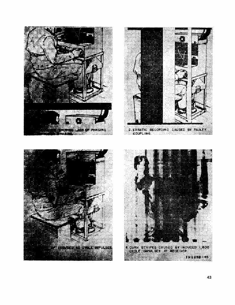
43

Section IV. OPERATION UNDER UNUSUAL CONDITIONS
34. GeneralThe operation of Facsimile Set AN/TXC-1(*)
may be difficult in regions where extreme cold,heat, humidity and moisture, sand conditions,etc., prevail. In the following paragraphs, instruc-tions are given on procedures for minimizing theeffect of these unusual operating conditions.
35. Operation in Arctic ClimatesSubzero temperatures and climatic conditions
associated with cold weather affect the efficientoperation of equipment. Instructions and pre-cautions for operation under such adverse condi-tions follow:
a. Handle the equipment carefully.b. Keep the equipment warm and dry. Do not
allow the temperature of the fork oscillator unitto go below +32° F. Although the fork oscillatoris a sealed unit, extreme changes in temperaturewill cause the 1,800-cps output of the fork oscil-lator to change, resulting in objectionable skewon the received copy. Changes in the RB +voltage also will affect the output frequency of thefork oscillator. If the set is not in a heated in-closure, construct an insulated box for the set.Keep resistor heaters (if available) turned on, pro-vided this does not overtax the power supply. Ifthis method is impracticable, keep the filament ofvacuum tubes lighted constantly, unless this alsoovertaxes the power supply. Maintain the tem-perature of the developer solutions as close aspossible to +68° F.
c. Locate the equipment inside a heated in-closure where there is no danger of a cold draftstriking the glass tubes when a door is opened.A sudden draft of cold air often is sufficient toshatter the glass envelope of a heated tube. Ifthe inclosure is so constructed that this precautionis impossible, place a blanket or some barrier be-tween the source of the draft and the equipment.
d. When equipment which has been exposed tothe cold is brought into a warm room, the equip-ment will sweat and the lenses will become foggedwith moisture condensation. This will continueuntil the equipment reaches room temperature.When the equipment has reached room tempera-ture, dry it thoroughly. This condition also arises
when equipment warms up during the day aftere x p o s u r e d u r i n g a c o l d n i g h t .
36. Operation in Tropical ClimatesFor operation in tropical climates, the equip-
ment may be installed in tents, huts or, when nec-essary, in underground dugouts. When equip-ment is installed below ground or when it is set upin swampy areas, moisture conditions are moreacute. Ventilation is usually very poor, and thehigh relative humidity causes condensation ofmoisture on the equipment whenever the tempera-ture of the equipment becomes lower than thesurrounding air. To minimize this condition, placelighted electric bulbs under the equipment.
37. Operation in Desert Climates
a. Conditions similar to those encountered intropical climates often prevail in desert areas.Use the same measures to insure proper operationof the equipment.
b. The main problem arising with equipmentoperation in desert areas is the large amount ofsand, dust, or dirt which enters the moving partsof the equipment such as motor and drum, leadscrew, etc. The ideal preventive precaution is tohouse the equipment in a dustproof shelter.Since such a building seldom is available andwould require air conditioning, the next best pre-caution is to make the building in which theequipment is located as dustproof as possible withavailable materials. Hang wet sacking over thewindows and doom; cover the inside walls withheavy paper. Secure the side walls of tents withsand to prevent their flapping in the wind.
c. Never tie power cords, signal cords, or otherwiring connections to either the inside or the out-side of tents. Desert areas are subject to suddenwind squalls which may jerk the connections looseor break the lines.
d. Keep the equipment as free of dust as pos-sible. Make frequent preventive maintenancechecks (pars. 40-43). Pay particular attention tothe condition of the lubrication of the equipment.Excessive amounts of dust, sand, or dirt that comeinto contact with oil and grease result in grit,which will damage the equipment.
44

CHAPTER 3
ORGANIZATIONAL MAINTENANCE
Section I. ORGANIZATIONAL TOOLS AND EQUIPMENT
38. Tools Used With Facsimile SetA N / T X C - 1 ( * )
The following organizational maintenance toolsare used with Facsimile Set AN/TXC-1(*):
1 Tube Puller TL-201 (fig. 73).1 Screwdriver TL-467/U: 2½" blade, 5/32"
tip, 5" lg o/a; w/2 blades.1 Screwdriver, 4-inch blade; 3/16 inch wide by
.032 inch thick bit.1 Screwdriver TL-359/U; 6" lg blade; 11¾”
lg o/a.1 Weighing Scale (for checking clutch tension)
8-24 ounce.1 Wrench TL-567/U, Allen type, hexagonal
key for No. 5 set screws.1 Allen wrench, for No. 6 Allen set screws.
39. Materials Required for OrganizationalMaintenance of Facsimile SetA N / T X C - 1 ( * )
The tools and materials listed below are notsupplied with Facsimile Set AN/TXC-1(*) butare required for maintaining the equipment andmay be secured through regular supply channels.
Abrasive, crocus cloth; 9” x 11” sheetBrush, cleaning; ½” w x 527/32 lgBrush, oval; sash; 1“ x 9¾” lgBrush TL-72: camel’s hair; ½” w; flatBurnisher, contact; pen type with pocket clipCarbon tetrachlorideCheesecloth, bleached; 36” wCleaner, lens; Kodak 1-oz bottleCleaning pasteLens tissue, 3“ x 5“Orangewood stickPaper, sand; #0000Polish, metal; pasteSolvent, Dry Cleaning (SD) (Fed spec P-S-661a)
Section Il. PREVENTIVE MAINTENANCE SERVICES
40. Definition of Preventive MaintenancePreventive maintenance is work performed on
equipment (usually when the equipment is not inuse) to keep it in good working order so that break-downs and needless interruptions in service will bekept to a minimum. Preventive maintenancediffers from trouble shooting and repair since itsobject is to prevent certain types of trouble fromoccurring.
41. General Preventive MaintenanceTechniques
00 sandpaper to remove corrosionexcept on or near mechanical parts, such as plugs.
b. Use a clean, dry, lint-free cloth or a dry brushfor cleaning.
(1)
(2)
If necessary, except for electrical contacts,moisten the cloth or brush with solvent(SD); then wipe the parts dry with acloth.Clean electrical contacts with a clothmoistened with carbon tetrachloride;then wipe them dry with a dry cloth.
Caution: Repeated contact of carbontetrachloride with the skin or prolongedbreathing of the fumes is dangerous.Make sure adequate ventilation is pro-vided.
c. Clean carbon deposits from the face of thedrum with a clean cloth dampened with water.Use only enough water to moisten the cloth. Donot wet the lead screw or the adjacent surfaces.
45

After cleaning, dry the drum thoroughly andpolish it with a clean, dry cloth.
d. Clean the stylus assembly with a soft bristlebrush. Do not disturb the adjustment. Use asoft brush to clean the transmitter lens adjacentto the stylus assembly. Avoid touching thelamps with the bare fingers.
e. Clean the drum shaft, and keyway, and theguide rail with a cloth dampened in solvent (SD).Wipe them dry with a clean lint-free cloth. Usea small, stiff brush dipped in solvent (SD) toclean the lead-screw threads while the motor isrunning. Wipe it dry with a clean, lint-free cloth.Apply a small amount of oil to the lead screw.
f. Clean rust and corrosion from photographictrays with fine sandpaper or emery cloth. If theprotective coating has worn off and the trays arecorroded, replace the trays if possible. In anemergency, corroded trays may be coated withparaffin or wax. Warm the tray so that theparaffin or the wax will flow.
g. To clean the drum feed mechanism, removethe four screws in the retaining ring (figs. 117 and118) and slide the cam plate and retaining ringfree of the feed mechanism. Do not drag thering over the threads of the lead screw. Removethe half nut retainer plug and slide the half nutand spring from the holder. Remove and cleanonly one half nut at a time so there will be nomistake in restoring it to the proper holder.Clean the holder, half nut, and spring with a smallbrush dipped in solvent (SD). Dry thoroughlywith a clean, lint-free cloth. Clean the cam platewith a cloth dampened with solvent (SD), anddry thoroughly with a clean, lint-free cloth.Reassemble in the reverse procedure of disassem-bly; see that the half nut retaining plugs areflush with the outer edge of the holder. Thisprovides proper tension for the spring, and allowsclearance for the drum cam plate.
h. If available, a vacuum cleaner may be usedto remove dust from inaccessible places. Becareful or mechanical damage from the air blastmay result.
i. Check the motor current daily. It should bebetween 60 and 70 on the motor current meter.
j. For further information on preventive main-tenance techniques, refer to TB SIG 178, Preven-tive Maintenance Guide for Radio CommunicationEquipment.
42. Use of Preventive Maintenance Forms(figs. 24 and 25)
a. The decision as to which items on DA Forms11-238 and 11-239 are applicable to this equip-ment is a tactical decision to be made in the caseof first echelon maintenance by the communicationofficer/chief or his designated repreaentative, andin the case of second and third echelon mainte-nance, by the individual making the inspection.Instructions for the use of each form appear onthe reverse side of the form.
b. Circled items in figures 24 and 25 are par-tially or totally applicable to Facsimile SetAN/TXC-1(*) and Rectifier Power Unit PP-86(*)/TXC-1. References in the ITEM blockare to paragraphs in the text which containadditional maintenance information.
43. Performing Preventive MaintenancePerform the following preventive maintenance
operations at the intervals indicated, unless theseintervals are reduced by the local commander.
Caution: Tighten screws, bolts, and nutscarefully. Fittings tightened beyond the pressurefor which they are designed will be broken ondamaged.
a. External Preventive Maintenance.(1)
(2)
(3)
(4)
(5)
(6)
(7)(8)
Check for completeness and satisfactorycondition of the equipment and the spareparts (pars. 6 and 7).Check the site for the location and instal-lation of the equipment for normaloperation (par. 12).Remove dirt, dust, moisture, and corro-sion from the carrying handles, motorcover, equipment cover, binding posts,base, and drum.Inspect the motor housing and equipmentcover for rust, indentures, scratches, andperfect fit. Inspect the fuses for suit-ability and seating.Check the engaging lever and clamp baron the drum for positive action (fig. 117).Inspect the START PHASE, ON-OFF,30RPM-60RPM, and the STANDBY-MON-TALK switches for positive action(figs. 13 through 16).
Check for normal operation.Inspect, clean, and tighten the GAINand CONTRAST controls, and the cableconnections (figs. 148, 149, and 150).
46

TM2258-87
Figure 24. DA Form 11-238.
4 7

TM2258-88
Figure 25. DA Form 11-239.
4 8
(9) Inspect the speaker case for rust,scratcher dirt, and moisture. Tightenall screws (fig. 5).
(10) Inspect the speaker cord for breaks,frayed insulation, dirt, and moisture.Inspect the plug and all connections(fig. 5).
(11) Inspect cabling for mildew, tears, andfraying.
(12) Inspect for looseness of accessible itemssuch as switches, jacks, knobs, trans-formers, motor mount, and drum (figs.127 through 137).
(13) Inspect and clean the DB METERwindow and the clutch window.
(14) Remove dirt, dust, and grease from thelead screw and meters (fig. 119).
(15) Lubricate the equipment in accordancewith instructions contained in the lubri-cation order (par. 44). Inspect theweatherproofing (pars. 48-53).
b. Internal Preventive Maintenance.Caution: Disconnect all power before per-
forming the following operations. Upon comple-tion, reconnect power and check for satisfactoryoperation.
(1)
(2)
(3)
Inspect electron tubes for loose envelopesand cracked sockets (figs. 9 and 10):clean them carefully.Inspect fixed capacitors for leaks, bulges,and discoloration (figs. 129 and 130).Inspect resistors for cracks, chipping,
(4)
(5)
(6)
(7)
(8)
(9)
Inspect terminals of large fixed capacitorsand resistors for corrosion, dirt, and loosecontacts.
Clean and tighten switches and interiorsof chassis not readily accessible (figs. 134-137).Inspect terminal blocks for loose connec-tions, cracks, and breaks.
Remove dirt and grease from the motor.Inspect the mounting screws and wireconnections. Lubricate the equipmentin accordance with applicable Depart-ment of the Army Lubrication Order(par. 44).
Clean and tighten connections for trans-formers, chokes, potentiometers, andrheostats (figs. 134-137).
Inspect transformers, chokes, and all con-trols for overheating.
(10) Inspect for worn or loose parts.
(11) Check the moistureproofing and fungi-proofing (par. 48).
(12) Check for corrosion at all soldered con-nections. Inspect all wiring.
(13) Clean all key type switches. Inspectthe contacts for proper contact and burnspots.
(14) Inspect and clean the lenses and lampsin the optical systems. Check the lens
blistering, discoloration, and moisture(figs. 129 and 130).
assemblies for looseness (figs. 120, 121,and 122).
Section Ill. LUBRICATION
44. Department of the Army LubricationOrders
Department of the Army lubrication orders areillustrated, numbered, and dated cards or decalco-mania labels that prescribe approved organiza-tional lubrication instructions for mechanicalequipment which requires lubrication by usingorganizations. Current available lubrication or-ders are listed in the latest issue of DA Pamphlet310-4, Index of Technical Manuals, TechnicalRegulations, Technical Bulletins, Supply Bulle-tins, Lubrication Orders, and Modification WorkOrders. Lubrication orders should be requisi-tioned in conformance with instructions and listsin DA Pamphlet 310-4.
a. Compliance with Department of the ArmyLubrication Orders. Instructions contained inlubrication orders are mandatory and supersedeall conflicting lubrication instructions of an earlierdate. Applicable lubrication orders which areavailable must be obtained and carried with theequipment at all times, and fully complied with.Difficulties experienced in obtaining and comply-ing with such orders will be reported throughtechnical channels.
b. Location of Department of the Army Lubrica-tion Order. Lubrication Order 11-2258, FacsimileSets AN/TXC-1, AN/TXC-1A, AN/TXC-1B,AN/TXC-1C, and AN/TXC-1D, is located on thetop right side of the chassis base of Facsimile
49

Transceiver TT-1(*)/TXC-1 under the lead screwshaft.
45. Approved Lubricants for FacsimileSet AN/TXC-1(*)
The following chart lists the lubricating ma-terials necessary when servicing Facsimile SetAN/TXC-1(*).
Symbol Standard nomenclature
PL Special Oil, Lubricating, Preservative, Special.G L Grease, Aircraft and Instruments.OCW Oil, Clock and Watch.
46. Lubrication TechniquesClean the parts thoroughly before applying
lubricant. Be sure that the parts are free of dirt,dust, corrosion, and old lubricants. The followingparagraph outline the methods, procedure, andmaterials to be used when cleaning equipmentpreparatory to lubrication. The instructions areapplicable in common to Facsimile Sets AN/TXC-1, -1A, -1B, -1C, and -1D unless otherwise noted.For additional information on cleaning, refer toparagraphs 40 through 43 for preventive mainte-n a n c e .
a. Lead Screw, Guide Rail, Drum Shaft, and Key-way (fig. 26). Disassembly is not required forcleaning and lubricating these items. Thoroughlyclean the parts as outlined in paragraph 41e.Lubricate as outlined in LO 11-2258 (fig. 26).
b. Secondary Clutch (fig. 26). No parts need beremoved or any adjustments disturbed to cleanthe dog latch cam plate. Clean the cam platewith a lint-free cloth dampened with solvent (SD).Any portion which cannot be reached easily canbe cleaned by covering an orangewood stick withthe dampened cloth. Dry thoroughly with alint-free cloth. Lubricate according to LO 11-2258(fig. 26).
c. Motor Worm and Gear (fig. 26). Clean themotor worm and gear with a lint-free cloth damp-ened with solvent (SD). Clean in between theteeth by covering an orangewood stick with thedampened cloth and running it between the teeth.Dry with a lint-free cloth. Lubricate accordingto LO 11-2258 (fig. 26). To perform this operationon Facsimile Sets AN/TXC-1B and -1C, firstremove the gear case cover.
47. Lubrication under Unusual Conditions
The lubricants listed in paragraph 45 may beused in all temperature. The intervals listed inthe lubrication order (fig. 26) are based on 8-hournormal daily use. When the equipment is usedmore than 8 hours daily, or is used in tropicalclimates, lubricate it more often. For example,if the equipment is in use 16 to 20 hours daily,lubricate after each 3 hours of operation. Thelubrication periods can be determined by frequentinspection of all lubrication points.
Section IV. WEATHERPROOFING
48. Weatherproofing Proceduresa. Genaral. When electronic equipment is
operated under the severe climatic conditionswhich prevail in the tropical, arctic, or desertregions, it requires special treatment and mainte-nance. Fungus growths, insects, dust, corrosion,salt spray, excessive moisture, and extremetemperatures are harmful to most materials.
b. Tropical Maintenance. Because fungusgrowth, insects, corrosion, salt spray, and excessivemoisture affect most materials in a harmfulmanner, a special moistureproofing and fungi-proofing treatment is used and, if properly applied,it provides a reasonable degree of protection.Refer to TB SIG 13 (Moistureproofing and Fungi-proofing Signal Corps Equipment), and TB SIG 72(Tropical Maintenance of Ground Signal Equip-ment) for detailed descriptions of the varnish-
50
spray method of applying moistureproofing andfungiproofing and the supplies and equipmentrequired for this treatment. The followingproblems may be encountered:
(1) Resistors, capacitors, coils, chokes, trans-
(2)
(3)
(4)
former windings, etc., fail because of theeffects of fungus growth and excessivemoisture.Electrolytic action often visible in theform of corrosion takes place in resistors,coils, chokes, transformer windings, etc.,and eventually causes breakdown.
Hook-up wire insulation and cable insula-tion break down. Fungus growth accel-erates deterioration.Moisture forms electrical paths on ter-minal boards and insulating strips, andcauses flashovers and cross talk.

LO 11-2258
Figure 26.
51

49. Moistureproofing and FungiproofingAfter Repairs
If the coating of protective varnish is puncturedor broken during repair, and if a complete treat-ment is not needed to reseal the equipment, applya brush coat to the affected part. Be sure thebreak is sealed completely.
50. WinterizationSpecial precautions are necessary to prevent
poor performance or total operational failure ofequipment in subzero temperatures. Most signalequipment can be used in winter if difficultiescommon in low temperatures are anticipated andprecautions are taken to prevent them. For oper-ational purposes, place the equipment in heatedrooms whenever possible. Take measures to keepthe temperature of the fork oscillator unit above+32° F. Refer to TB SIG 66 (Winter Main-tenance of Signal Equipment), and TB SIG 219(Operation of Signal Equipment at Low Temper-atures) for complete information. The followingproblems may be encountered:
a. Steel shrinks and becomes brittle in subzerotemperatures.
b. Glass is especially susceptible to sudden tem-perature changes. The difference between a low airtemperature and the warmth of a man’s breathmay be sufficient to shatter a lens.
c. Pure rubber resists cold weather well, butcertain types of synthetic rubber are unreliableand become brittle.
d. Canvas freezes and loses its pliability in coldweather.
e. Lubricants become stiff, causing the movingparts to stick and dry.
51. RustproofingSignal Corps equipment operated in desert
localities is affected by the extremely high temper-atures and the amount of dirt, dust, sand, andother foreign matter in the air. Keep such ele-ments from filtering into lubricated parts. Coverthe equipment when it is not in use. Thorough
cleanliness is imperative. Instead of merelyadding new lubricants at regular intervals, when-ever practicable clean and lubricate all movingparts. If it is possible, inspect and clean theequipment daily. In any case, inspect the airfilters and similar protective devices every dayand clean them whenever necessary. Refer toTB SIG 75 (Desert Maintenance of Ground SignalEquipment). Some of the problems encounteredare the following:
a. Lubricants become thin and drain rapidlyfrom moving metal and fiber parts.
b. Foreign matter, such as dirt, dust, and sand,acts as an abrasive. This causes excessive wear,clogging of air cleaners, and impeding of the flowof air.
52. Lubrication
The effects of extreme cold and heat on materialsand lubricants are explained in TB SIG 69(Lubrication of Ground Signal Equipment). Ob-serve all precautions outlined in TB SIG 69 andpay strict attention to all lubrication orders whenoperating the equipment under conditions ofextreme cold or heat.
53. Rustproofing and Painting
a. When the finish on the transceiver and powerunit chassis or the table has been badly scarredor damaged, rust and corrosion can be preventedby touching up bared surfaces. Use No. 00 orNo. 000 sandpaper to clean the surface to the baremetal until a bright smooth finish is obtained.
Caution: Do not use steel wool. Minuteparticles frequently enter the equipment and causeharmful internal shorting or grounding of circuits.
b. When a touch-up job is necessary, apply paintwith a small brush. Remove rust from the caseby cleaning corroded metal with solvent (SD).In severe cases, it may be necessary to use solvent(SD) to soften the rust and to use sandpaper tocomplete the preparation for painting. Paint usedwill be authorized and consistent with existingregulations.
Section V. TROUBLESHOOTING AT ORGANIZATIONAL MAINTENANCE LEVEL
54. General is based on the performance of the equipment anda. The troubleshooting and repairs that can the use of the senses in determining such troubles
be performed at the organizational maintenance as burned-out tubes, cracked insulators, etc.level (operators and repairmen) are necessarily b. Paragraphs 55 through 58 help in determininglimited in scope by the tools, test equipment, which component is at fault and in localizing thereplaceable parts issued, and by the existing fault in that component to the defective stage ortactical situation. Accordingly, troubleshooting items such as a tube or fuse.
52

55. Visual Inspection
a. Before making operational tests, examinethe equipment for one or more of the followingdefects:
(1)(2)(3)(4)(5)(6)(7)
(8)
Tubes out of sockets.Tubes 1oose in sockets.Broken exciter lamp.Damage to lead screw.Blown rectifier power supply fuse.Blown motor fuse.Worn, broken, or disconnected cords orplugs.Wires broken because of excessive vibra-tion.
b. When failure is encountered and the causein not immediately apparent, check as many ofthe above items as is practicable before startinga detailed examination of the component parts ofthe system. If possible, obtain information fromthe operator of the equipment regarding perform-ance at the time trouble occurred.
56. Sectionalization of Trouble to Component
Sectionalization consists of determining whetherthe trouble is in the transceiver or the powersupply.
a. Operate the set and observe its performance.Refer to the equipment performance check list(par. 58) for normal operating indications.
b. If the entire equipment is dead, the troubleis undoubtedly in Rectifier Power Unit PP-86(*)/TXC-1. Check the fuse (figs. 158 through 161)and interconnecting cable.
c. If a tone is not heard in the motor lamina-tions, and the exciter lamp does not light, thetrouble is probably in the fork oscillator unit, orthe trouble may be in the lamp amplifier sectionof Rectifier Power Unit PP-86(*)/TXG1. Checktubes V17 through V21 and V23.
d. Use procedure similar to the simple checks
given in a through c above to isolate trouble toa particular init.
57. Troubleshooting by Using EquipmentPerformance Check List
a. General. The equipment performance checklist (par. 58) will help the operator to determinewhether Facsimile Set AN/TXC-1(*) is function-ing properly. The check list gives the item to bechecked, the conditions under which the item ischecked, the normal indications and tolerancesof correct operation, and the corrective measuresthe repairman can take. To use this list, followthe items in numerical sequence.
b. Action or Condition. For some items, theinformation given in the action or conditioncolumn consists of the settings of various switchesand controls under which the item is to be checked.For other items, it represents an action that mustbe taken to check the normal indication given inthe normal indications column.
c. Normal Indications. The normal indica-tions listed include the visible and audible signsthat the operator will perceive when the itemsare checked. If the indications are not normal,the repairman should apply the recommendedcorrective measures.
d. Correction Measures. The corrective meas-ures listed are those the operator can make with-out turning in the equipment for repairs. Refer-ence in the table to a paragraph in chapter 6indicates that the trouble cannot be correctedduring operation and that troubleshooting byan experienced repairman is required. If the setis completely inoperative or if the recommendedcorrective measures do not yield results, trouble-shooting is necessary. If the situation requiresthat communication be maintained, and if theset is not completely inoperative, the operatormust maintain the set in operation as long as it ispossible to do so.
53

58. Equipment Performance Checklist
ItemNo.
12
8
4
5
6
7
8
9
Item Action or condition
Power ON-OFF switch.. Turn to OFF position.Selector switch Set to SET RANGE posi-
tion.Drum Disengage; move drum
to extreme right.Connections to line Make connections for
wire or radio circuit asdescribed in paragraphs15 and 18.
Connection to power Jones plug connected tosource. transceiver recptacle.
Communication Establish communicationwith other station.
Method of recording Arrange method of record-ing with operator atother station.
Copy Place copy on scanningdrum.
Normal indications
Power ON-OFF switch Turn to ON position Allow to warm up at least10 minutes. An 1,800ops tone is heard in themotor laminations.Pilot light and exciterlamp light.
Corrective measures
Check fuse in RectfierPower Unit PP-86(*)/TXC-1. Check V21through V23. CheckV1 through V6.
54

a. Facsimile Transceicer TT-1*/TXC-1 (Transmitting).
Item
—!tsmNo.—
10
11
12
13
14
18
16
17
CONTRAST and GAINcontrols.
selector switch ---------
Maximum and minimumsignals.
Motor ----------------
Phasing pulees ---------
Phasing check ----------
Transmitting copy --.--
Stopping transceiver----,
Action or condition
Adjust for proper con-trast and correct out-put.
Turn to TRANSMITpoi4ition.
Send maximum signal for15 seconds, then sendm~ximum and mini-mum signals for 5 sec-onds each.,
Operate START switch- -
Move drum so light shineson phasing ring.Transmit about 25phasing pulses.
Receiving operator mayaak for phasing check.
Engage drum feed mech-anism.
Operate selector switchto STANDBY. Ah30
operate MOTOR ON-MOTOR OFF switchon Facsimile Trans-ceiver TT-1/TXC-l toMOTOR OFF. Dis-engage drum feedmechanism.
Normal Indications
DB METER indicatescorrect contrast (pars.25 and 26).
DB METER indicatescorrect contrast. Re-ceiving operator checkscontraat and sets GAINcontrol.
Motor starts and drivesdrum. MOTOR CUR-RENT meter (M2)indicates between 70 to76 milliamperes.
Pointer of DB METERwill flick once for eachrevolution of drum.Stop arm driving dogtrip arm (fig. 14).
----------------------
Scanning drum moves toleft along lead screw.
Drum stops---.---_----
Corrective rne=ures
Check adjustment of ex-citer lamp. ReadjustCONTRAST controland reset GAIN.Check balance (R42).Check V1O, Vll, V12,and V13.
Same as item 10. Sendsignali until reeeivingoperator is ready.
Check motor fuse. Read-just motor currentpotentiometer R93 (fig.169 and par. 71).
Check V4, V5, and V6.Check tubes V15. and V 16.
Check tube V25 forglow. Check RB+meter M3 for correctvoltage, and adjust RB +potentiometer for read-ing of 250 volts.
Send more phasing pulses.
Check if selector switch isat TRANSMIT. Checkfor dirt on letid screwthreads, Check condi-tion of half nuts.
Check position ofST AN D13Y-MON -TALK switch; must alsobe at STANDBY,
55

b. Facsimile Transceiver TT-1*TXC-1 (Receiving, Direct Recording).
[tmNo,
18
19
m21
22
a2
B4—
MO
Dimot reoording paper..
Seletir mdtoh.... . . . . .
Blower mvitoh . . . . . . . . .GAIN oontrol ---------
Phasing ---------------
Raoetting copy --------
Mopping trmuweiver . . . .
AOUO?I or ooadltloo
FMttM to mmnning drum
Turn to RECORD DI-RECT,
Turn to ON-----------COntaot transmitting op-
erator to oheok signallevele. When trans-mitting operator sendsmaximum eigml, ad-juet GAIN oontrol forproper reading on DBMETER. Cheek con-tmet on maximum andmlnhnum eignkb.
Wrt motor and phaeetrhmeiver.
Turn eeleotor mvitoh toRECORD DIRECT;engage drum feedmeolmniem,
Same aaetep 17.. -------
Normal kIdlouIoM
Metdlio or Imokeide to-werd drum. No wrin-kles in pnpero
Blower motor operatea.Di!?erenoe in msximum
end minimum shouldbe *me Ae at transmit-ting sktion within 2db.
Drum rotates, 900 ope or1,800 ope tone heudfrom motar lamine-tione.
Drum moves ta the left810ng lead aorews,&ylua reoorde; slighttinge of emoke emittedat stylus.
S8meeaotep 17---------
OonwtIve mauum
Releese meording ~perand refaeten to drum,
Cheek tubes V1O, Vll,V12, and V14. Cheekline if poenible. (If r~dio oirouit is being used,eheok for proper re-oeiver output imped-anoe matoh (par. I&).)
Cheek motcw fuee. Cheekfor looked-up oluteh.cheek tubee in fork-oeeiUetOr unit. cheektubee V4, V5, snd V6,looee Jonee plug, andV26.
Cheek copy, replaoe stylueif neoeseary (par, 118).Remove foreign mstterfrom lead sorew. Ex-amine lmlf-nuts.
Uune ae step 17.
56
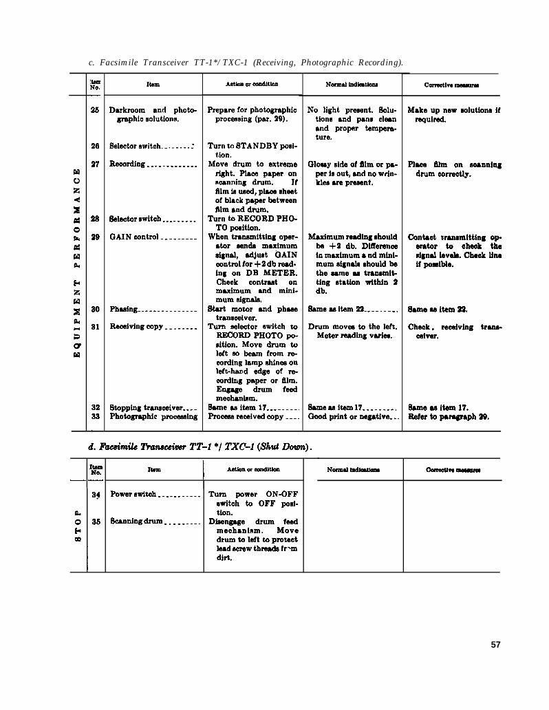
c. Facsimile Transceiver TT-1*/TXC-1 (Receiving, Photographic Recording).
[Nte
—
25
26
27
28
29
30
31
3233—
Item
Dsrkroom and photm-graphio solutions.
Selector awitoh.. . . . . . . .
Recording -------------
Seleotor owitah ---------
GAIN oontrol ---------
Phming-..------------
Reoejving copy --------
Stopping trancoeiver----Photographic prooeaeing
Aotlom or woditlom
Prepare for photographicprocessing (par. 29).
Turn w STANDBY posi-tion.
Move drum to extremeright. Place paper onmanning drum. Iffilm ic used, plaoa sheetof black paper betweenfilm and drum,
Turn to RECORD PHO-TO pmition.
When transmitting oper-ator sendo maximumsignal, adjust i3AINoontrol for +2 db read-ing on DB METER.Cheek oontraat onmaximum and mini-mum signala.
Start momr and phasetransceiver.
Turn seleotor switch w-RD PHOTO pO-nitjon. Move drum toleft 00 beam from *cording lamp chines onleft-hand edge of re-cording paper or film.Engage drum feedmeohanimm.
Same acitem 17---------Prooecc reoehwd copy ----
No light precent. Solu-tione and pans cleanand proper tempera-ture.
(31OMIY aide of film or pa-per is out, bnd no wfin-klcs arc pracant,
Maximum reading shouldbe +2 db. Differencein maximum ● nd mini-mum signdc ohould bethe came aa trmmmit-tlng etation within 2db.
Sftmeaa Nam22--- . . . . . .
Drum movec to the left.Meter reading varies,
Same aai@m 17- . . . . . . . .Good print or negative-..
d. F&mile llwweiver TT-1 */ TXC-l (Shut Down).
It&II
——
Item I Aotkm or aondltlonI
Power stitch -----------
Soanning drum ---------
Turn power ON-OFFswitch to OFF posi-tion.
Disengage drum feedmechaninm. Movedrum to left to protaotlead aorew threado fr*mdirt.
Normal Indlmtlom Oorreouve ~
Make up new solutiono ifrequired,
Plaea film on soannlngdrum oorreotly.
Contaot wmamitting op.erator to oheek thedgnal leveh. Chaok llneif poaclble,
Same ae item 22.
Cheek. reeaiving trana-oeiver.
Same ae item 17.Refer to paragraph 29,
Normal lodiaMoIu Uormouw maMnm8
57

CHAPTER 4
AUXILIARY EQUIPMENT
Section I. CONVERTER CV-2C/TX
59. Block Diagram(fig. 27)
Converter CV-2C/TX is an electronic devicewhich is used between the facsimile transceiverand the radio circuit in transmission and receptionof facsimile signals by the subcarrier frequencymodulation (SCFM) method. Figure 27 is ablock diagram that shows Converter CV-2C/TXconnected in an am SCFM application. Whentransmitting, the converter changes 1,800-cps amsignals from the facsimile transceiver into fre-quency-modulated voice-frequency signals whichmodulate a conventional radiotelephone trans-mitter. The transmitted signal consists of a rfcarrier on which is superimposed a constant levelaf modulation. The frequency of the af modula-tion is varied in accordance with the facsimilesignals. When receiving, the radio signal is pickedUp by a conventional am communication receiver.The receiver output, which is fed into the con-verter, consists of voice-frequency signals. Theconverter changes these signals into am signals,which are fed to the receiving facsimile transceiver.This type of circuit is less affected by fading andinterference than transmissions using conventionalam. Complete information on Converter CV-2C/TX is contained in TM 11-2252A.
60. Applicationa. Connections. Locate Facsimile Transceiver
TT-1(*)/TXC-1 and Converter CV-2C/TX sothat the front panel controls of both units can beoperated easily. The tuning eye on the frontpanel of the converter must be in view.
(1) Normal operation.(a) Insert the input cord of Converter
(b)
(c)
(d)
(e)
(f)
CV-2C/TX into the LINE jack on theright-hand end of Facsimile Transcei-ver TT-1(*)/TXC-1.Insert the connector plug of the acpower cord into the socket (PS1) onthe rear panel of the converter.
Insert the plug on the other end of theac cord into a 115-volt, 60-cps, acsource.Insert one end of Cord CD1019 intothe RADIO XMTR jack on the frontpanel of the converter and the otherend to the carbon microphone input ofthe radio transmitter.
Strap the GND and adjacent LINEterminal on the terminal board at therear of the converter.
Plug one end of Cord CD-1018 into theRADIO REC. jack (J5) on the front
Figure 27. Am-SCFM transmission and reception of facsimile signals, block diagram.
58

panel of the converter. Plug the otherend of this cord into the high-levelaudio output termination on the radioreceiver.
Note. When Converter CV-2C/TX isused in a radio facsimile circuit, the talk-backcircuit of Facsimile Transceiver TT-1(*)/TXC-1 is inoperative. However, carbonMicrophone T-17 (or equivalent) and Head-set HS-30 (or equivalent) are plugged intothe converter CARBON MIC. and MONI-TOR jacks, respectively, for voice com-munication and transmitter control.
(2) Remote operation of radio transmitter.If the radio transmitter is remotelylocated, use shielded two-conductor cablein place of Cord CD-1019 to connect itto the radio transmitter.
(a)
(b)
If the distance is great, connection tothe radio transmitter must be madefrom the LINE terminals at the rear ofthe converter. Remove the strapthat connects the GND terminal andthe adjacent LINE terminal, and usea telephone line or field wire to connectthe output of the converter to theradio transmitter.In either case, the line must be limitedto a length which will provide equalmodulation of the radio transmitter atthe 1,500- or 3,000-cps shift limits.
Note. The microphone plugged into theconverter cannot be used when connectionis made from the LINE terminals. A sepa-rate line to the transmitter must be usedunder these conditions.
b. Transmitting. Adjust Facsimile Trans-ceiver TT-1(*)/TXC-1 in accordance with thetype transmission to be made. Refer to para-graph 17.
(1) Operate power ON-OFF switch S4 tothe ON position, REC.-SEND switchS1 to the SEND position, SET MIN.-SET MAX. switch S5 to SET MAX.,SEND-STANDBY switch S6 to STAND-
(2)
(3)
(4)
(5)
(6)
(7)
(8)
BY, and 1500 2300-1800 3000 switchS2 to 1500 2300 position.With maximum signal being delivered byFacsimile Transceiver TT-1(*)/TXC-1,adjust FREQ. ADJ. control R2 formaximum closure of the tuning eye onConverter CV-2C/TX (+2 db readingon the DB METER).Operate the SET MIN.-SET MAX.switch to the SET MIN. position.Set Facsimile Transceiver TT-1(*)/TXC-1 to deliver minimum signal. Thetuning eye on the converter should beat maximum closure. If not, adjust thetransceiver CONTRAST control for max-imum closure.Return the SET MIN.-SET MAX.switch to the SET MAX. position.The tuning eye should be maximumclosure with a +2 db reading on theDB METER. If not, readjust theFREQ. ADJ. control.Operate the SEND-STANDBY switchto the SEND position.Adjust SEND GAIN control R21 onConverter CV-2C/TX far proper modu-lation of the transmitter.The transceiver and converter now areadjusted properly. Proceed as outlinedin paragraph 23c and d.
c. Receiving.(1) Operate REC.-SEND switch S1 to the
REC. position.(2) Tune in the carrier signal (maximum
indication on receiver). Adjust the rfand audio controls for a clear signal withminimum background noise.
(3) When the transmission begins (maximumand minimum signals), adjust FacsimileTransceiver TT-1(*)/TXC-1 for normaloperation as outlined in paragraph 28.
(4) If correct contrast cannot be obtained,increase the radio receiver audio outputby advancing the audio gain control.
Section Il. EXCITER UNIT O-5B/FR
61. General The exciter unit is used with Converter CV-Exciter Unit O-5B/FR is an electronic device 2C/TX to permit transmission of frequency-shift
which is used in place of the oscillator section of a facsimile signals over a cw radiotelegraph trans-cw transmitter to excite the transmitter with mitter when using Facsimile Set AN/TXC-1(*).frequency-shift signals according to a varying dc Complete information on Exciter Unit O-5B/FRor audio voltage which is fed into the exciter unit, is contained in TM 11-2205A.
59

Note. Exciter Unit O-5/FR or O-5A/FR can be usedwith Converter CV-2/TX or CV-2A/TX after minorchanges have been made in the circuit. Complete infor-mation on Exciter Units O-5/FR and O-5A/FR is con-tained in TM 11-2205.
62. RF Oscillator O-86/FRTRF Oscillator O-86/FRT is similar to Exciter
Unit O-5/FR or O-5A/FR that already has beenmodified for use with Converter CV-2/TX orCV-2A/TX. It can be used in place of ExciterUnit O-5/FR or O-5A/FR without modification.Refer to TM 11-2205 for complete information onRF Oscillator O-86/FRT.
63. ApplicationFigure 28 is a block diagram which shows how
Converter CV-2C/TX and Exciter Unit O-5B/FRare used in frequency-shift transmission and recep-tion of facsimile signals.
a. Transmitting. When transmitting, the 1,800-cycle am signals from Facsimile TransceiverTT-1(*)/TXC-1 are fed into Converter CV-2C/TX, where they are rectified. The output fromthe converter is in the form of a varying dcsignal that represents the envelope of the modu-lated, 1,800-cycle carrier. This varying dc signalis applied to the oscillator control tube in Exciter
Figure 28. Frequency-shift transmission and reception of facsimile signals, block diagram.
60

Unit O-5B/FR. The output of the exciter unitis a frequency-shift rf signal which shifts aboveand below a center frequency by an amountproportional to the varying dc signal producedby rectification of the 1,800-cps signal. Thisserves as the rf excitation for the cw transmitter.The transmitter output is a frequency-shift signal,shifting a total of 800 cycles between picture whiteand picture black; 400 cycles above and 400 cyclesbelow the assigned carrier frequency (a total of1,200 cps, ±600 cycles under the old shift limits)(fig. 29). Frequency-shift transmissions are ad-vantageous because they are affected less byfading and interference than transmissions usingconventional am and, in addition, the rf channelwidth required is less than when using am SCFM.
b. Receiving. When receiving frequency-shiftfacsimile signals, a conventional communicationreceiver that has a crystal-controlled temperaturecompensated hf oscillator and a stabilized beat-frequency oscillator should be used. Radio Re-ceiver R-390/URR or Radio Receivers BC-779,BC-794, and BC-1004 modified in accordancewith MWO SIG 11-866-4, Modification of RadioReceivers BC-779-(*), BC-794-(*) and BC-1004-(*) to provide for improved stability of the highfrequency oscillator circuit, are suitable in thisapplication. However, a conventional receivermay be used to pick up the frequency-shift radiosignal with a stable rf signal applied to its inputfrom Frequency Meter BC-221. Therefore, thebeat-frequency oscillator will not be required. Inboth methods, the incoming signal is heterodynedwith the local oscillator signal to produce an outputin the af range swinging from 1,500 to 2,300 cpsor from 1,800 to 3,000 cps, depending on whichshift limit is used (fig. 29). These fm voice-frequency signals are applied to the input ofConverter CV-2C/TX which converts them intoam af signals which are fed into the input of thereceiving facsimile transceiver.
64. Operation
After the equipments have been connected asshown in figure 28, apply the following operatinginstructions when using an 800-cps shift (1,500 to2,300 cps). Detailed instructions for connectingand adjusting Exciter Unit O-5B/FR are given inTM 11-2205A. Audio Oscillator TS-382A/U andElectronic Multimeter TS-505/U may be used toassist in properly setting up the equipment foroperation.
a. Setting Controls. The following proceduresets the controls of the facsimile transceiver, thethe converter, and the exciter unit to produce therequired carrier shift:
(1)
(2)
(3)
With maximum signal of +2 db from thefacsimile transceiver, adjust the exciterunit and the FREQ. ADJ. (R2) controlof the converter so that the transmitteroutput frequency is 400 cps above theassigned carrier frequency. Check byusing Audio oscillator TS-382A/U andtuning for zero beat.With minimum signal from the facsimiletransceiver, adjust the facsimile trans-ceiver until the transmitter output is 400cps below the assigned carrier frequency.This will require adjustment of theCONTRAST and GAIN controls of thefacsimile transceiver. While adjustingtransceiver controls, check again to besure that the maximum transceiver signalis maintained at +2 db. Do not makeany further frequency control adjust-ments on the exciter unit or the con-verter. Use Audio Oscillator TS-382A/Uto see that the change from minimumfacsimile signal to maximum facsimilesignal increases the transmitter outputfrequency by 800 cps. To do this, leavethe oscillator tuned as described in (1)above, and measure the frequency of thebeat note produced by the beating of theoscillator signal with the transmitteroutput signal. Use the beat note methodto measure the frequency of this 800-cyclenote either on a direct reading af meteror by comparison with an 800-cycle signalfrom an audio oscillator.To check the accuracy of the adjustmentsand to assist the receiving operator inadjusting the station, send a series ofmaximum and minimum level signals(high- and low-frequency signals), fol-lowed by a series of phasing pulses. Re-peat this sequence two or three timesbefore actually transmitting the copy.
Note. Allow at least ½-hour warm-up periodbefore making operating adjustments.
b. Transmitting. Negative transmission of fac-simile copy is preferable, although copy may betransmitted either negative or positive. The
61

controls of the facsimile transceiver are used intheir normal manner to select either positive ornegative transmission as required. In either case,adjust the system so that a minimum amplitudesignal · output from the facsimile transceiverproduces the lowest output frequency fromexciter Unit O-5B/FR and a maximum amplitudesignal output from the facsimile transceiverproduces the highest output frequency fromExciter Unit O-5B/FR. The frequency and fre-quency deviation at the output of Exciter UnitO–5B/FR will be multiplied by the radio trans-mitter frequency multipliers, but the transmitteroutput frequency must be kept to a maximumfrequency swing of 800 cps. This requires thatthe transmitter output frequency be 400 cps belowthe assigned carrier frequency when a minimumfacsimile signal is sent, and 400 cps above theassigned carrier frequency when a maximumfacsimile signal is sent. The actual outputfrequency of the transmitter will vary betweenthese two extremes from instant to instant inaccordance with the brightness or darkness of thetransmitted copy being scanned on the facsimiletransceiver drum. The following chart shows theactual transmitter output frequencies for min-mum and maximum facsimile signals (when theassigned rf carrier is 7,500 kilocycles (kc)), wheneither positive or negative facsimile transmissionsare being made:
Assigned carrier Amplitude of fac- Tranmitter outputfrequency simile signal
7,500 kc M i n i m u m 7 , 4 9 9 . 6 k c .
7 ,500 kc M a x i m u m 7 , 5 0 0 . 4 k c .
c. Receiving (fig. 29). The receiving stationmust be adjusted so that the highest received fre-quency is interpreted as a maximum amplitudesignal at the receiving facsimile transceiver, andthe lowest received frequency is interpreted as aminimum amplitude signal at the receiving fac-simile transceiver. To obtain this desired rela-tionship, the output of the receiver hf oscillatormust be on the hf side of the received rf signal.This will produce an af beat note (2,300 cps) atthe receiver output when the received rf signal isat its lowest frequency, and a low-frequency beatnote (1,500 cps) at the output of the receiver whenthe received rf signal is at its highest frequency.The received carrier frequencies are the same asthose assumed for the transmitting station, and
62
they produce the desired facsimile signals at theinput of the facsimile transceiver. The receivedcarrier swings over a total of 800 cycles and normalheterodyning action of the beat-frequency oscil-lator in the receiver produces a receiver outputwhich varies from 2,300 to 1,500 cps. The low-pass filter in Converter CV-2C/TX changes the2,300-cps signal into a minimum amplitude outputsignal and the 1,500-cps signal into a maximumamplitude signal. Received carrier frequenciesbetween the low extremity (7,499.6 kc) and thehigh extremity (7,500.4 kc) produce amplitudes inbetween minimum and maximum, which the re-ceiving facsimile transceiver prints as intermediateshades of gray between black and white. If thereceiver hf oscillator output is set to the low sideof the received carrier, the received picture toneswill be reversed. A positive transmission will bereceived as a negative, and vice versa.
Frequency of Frequency ofreceiver receiver hf
Frequency of Amplitude of re-receiver covered facsmile
carrier oscillator output signal
7 , 4 9 9 . 6 k c 7 , 5 0 1 . 9 k c 2 , 3 0 0 c p s M i n i m u m .
7 , 5 0 0 . 4 k c 7,501.9 kc 1 , 5 0 0 c p s M a x i m u m .
(1) When using receivers that do not usecrystal-controlled conversion, front-endinsertion of a highly stable heterodyningsignal is a necessity for satisfactory re-sults. The constant frequency output ofFrequency Meter BC-221 is ideal as asubstitute for crystal-controlled hf oscil-lator injection. The following proceduresets Frequency Meter BC-221 to the highside of the received carrier:
(a)
(b)
(c)
(d)
Tune in the facsimile signal and zerobeat the frequency meter to this signal.
Reduce the receiver rf gain control fora reading of approximately 1 on thereceiver S-meter.
Couple the output of Frequency MeterBC-221 to the receiver at the receiverantenna terminal.
Without disturbing the receiver rf gaincontrol, adjust the injection level byadjusting the coupling to the receiverfor a full-scale reading on the receiverS-meter (direct coupling, although notrecommended, may be necessary).
Note. The exact level will vary slightlyfor different receivers and can be determinedbest by the overall performance of thesystem.

(e)
( f )
Figure 29. Receiver rf relationships during reception of frequency-shift facsimile transmissions.
With the transmitting operator sendinga steady minimum signal (7,499.6 kcin this example), adjust FrequencyMeter BC-221 until the af output sig-nal from the radio receiver is exactly2,300 cps. Check to see that the fre-quency meter is tuned 2,300 cps (2.3kc) above the incoming signal (to7,501.9 kc in this example). Checkthis by varying the frequency meterdial through zero beat and by turningit to the highest frequency setting ofthe two settings that will produce a2,300-cps receiver output signal.Check the accuracy of the 2,300-cpssignal either on a direct reading afmeter or by comparing it with thesignal from an audio oscillator.With the transmitting operator sendinga steady maximum signal (7,500.4 kcin this example), and without changingthe setting of the frequency meter, thereceiver output signal should be ex-actly 1,500 cps. This can be checkedwith the direct reading af meter or by
(g)
(h)
comparison with the signal from anaudio oscillator.
Note. The facsimile transceiver producesan audible oscillation which is highly accu-rate. This can be used for checking the1,800-cycle signal from the receiver when the1,800- to 3000-cps shift limit is used.
Check the accuracy of the adjustmentsby listening to the series of maximumsignals, minimum signals, and phasingpulses which the transmitter operatorwill repeat two or three times.When phasing pulses are being receivedon positive transmissions (maximumsignal on black), the radio receiver out-put will be a steady 1,500-cps tone,interrupted onoe each second by a2,300-cps pulse. On negative trans-missions, during phasing, the radio re-ceiver output will be a steady 2,300-cpstone, interrupted once each second bya 1,500-cps pulse.
(2) Set up Facsimile Transceiver TT-1(*)/TXC-1 as outlined in paragraph 28.
63

CHAPTER 5
THEORY
Section I. GENERAL
65. Fundamentals of Facsimile EquipmentFacsimile equipment is used to transmit images
over an electrical communication system, Theseimages, called pictures or copy in facsimile ter-minology, may be maps, photographs, sketches,typewritten or printed text, or handwriting.
a. Operation Performed. The image that servesas facsimile copy or picture cannot be transmittedinstantly in its entirety. The three operationsnecessary to transmit and record the picture areas follows:
(1)
(2)
(3)
The breaking up of the picture in anorderly manner into a large number ofelemental areas of varying shades. Thisprocess is called scanning and is accom-plished by the facsimile transmitter.Transmission of electrical signals, repre-senting these individual elemental areas,to the facsimile receiver. Facsimilesignals are transmitted over wire andradio circuits.The interpreting of these electrical sig-nals and the rebuilding and recording ofthe original picture from them. Thisreversal of the transmitter scanningprocess is accomplished by the facsimilereceiver. The receiving transceiver mustbe accurately synchronized with thetransmitting transceiver to assure satis-factory reproduction.
b. Facsmimile Set AN/TXC-1( *). Facsimile SetAN/TXC-1(*) performs the basic operationsoutlined in a above in the following manner:
(1) The picture to be transmitted is mountedon a cylindrical drum, which revolves atthe rate of 1 revolution per second, inFacsimile Transceivers TT-1/TXC-1,TT-1A/TXC-1, TT-1B/TXC-1 andTT-1C/TXC-1. In Facsimile Sets AN/TXC-1C and -1D (Facsimile Trans-ceiver TT-1D/TXC-1, TT-1E/TXC-1,
64
(2)
(3)
or TT-1/XC-1), the drum rotates atthe rate of ½ revolution per second or 1revolution per second, depending on thesetting of motor speed control switch(30RPM-60RPM) S4. The drum travelsfrom right to left along a lead screw atthe rate of 12½ inches in 20 minutes whenrevolving at 1 revolution per second, andat the rate of 12½ inches in 40 minuteswhen revolving at ½ revolution per sec-ond. Light from an exciter lamp illu-minates a small area of the picture beingscanned and is reflected back through anaperture to a photocell. During thetransmission of a complete picture, thislight traverses every portion of the pic-ture as the drum slowly spirals past thefixed lighted area.At any instant, the amount of light re-flected back to the photocell is a measureof the lightness or darkness of the tinyspot of picture which is being scanned.A photocell transforms varying amountsof light into corresponding electricalsignals, which are amplified and trans-mitted over the facsimile circuit.Electrical signals received by the fac-simile receiver are amplified and serveto actuate a recording mechanism whichmakes a permanent record, spot by spot,on the recording paper on the syn-chronized receiver drum until the com-plete original picture is reproduced.Facsimile Set AN/TXC-1(*) reproduceseither photographically, with a controlledlight source shining on photographicpaper film, or directly, with a stylus thatburns a white protective coating fromspecially prepared recording paper. Syn-chronization is obtained by constantlydriving both receiving and transmitting

drums with synchronous motors operat-ing at identical speeds. Phasing is ac-complished by transmitting a series ofphasing pulses just prior to each facsimiletransmission. These pulses operate aclutch mechanism which phases the re-ceiving drum to the transmitting drum.
66. Block Diagrams
Figures 30, 31 and 32 show the various stages ofFacsimile Set AN/TXC-1(*).
a. Electrical Circuits. The complete electricalcircuit of Facsimile Set AN/TXC-1(*), includingFacsimile Transceiver TT-1(*)/TXC-1 and Rec-tifier Power Unit PP-86(*)/TXC-1, may bebroken down by functions into the following eightprincipal circuits:
(1) Signal source at 1,800 cycles. The forkoscillator unit (V1, V2, and V3) generatesa steady 1,800-cycle audio signal for usein several other circuits (figs. 30 and 34).
(2) Photocell bridge modulator. The photo-cell bridge modulator circuit (V24), builtaround a type 1645 photocell tube (type5652 in Facsimile Transceivers TT-1D/TXC-1, TT-1E/TXC-1, and TT-1F/TXC-1), is used on transmission only.It amplitude modulates the 1,800-cyclesignal in accordance with variations inlight intensity of the small portion of thetransmitted copy being scanned at anyinstant.
(3) Signal amplifier circuit. The signal am-plifier circuit (V10, V11, V12, V13, andV14) amplifies the 1,800-cycle am signal(figs. 51 through 54). One-half of V13is used to drive V14 on direct recordingsonly. The other half of V13 is con-nected as a meter amplifier for operationof the DB METER. On transmission,the photocell bridge modulator feeds thesignal amplifier circuit, which feeds theline. On reception, the signal on the lineis fed to the signal amplifier circuit whichdrives either the stylus for direct record-ing or the recorder lamp for photorecording. Tubes V10, V11, and V12also are used in the talk-back circuit.
(4) Phasing circuit. The phasing circuit(V15 and V16) is used only for phasingthe facsimile receiver. A series of phas-ing pulses from the transmitter actuatea clutch mechanism and phase the
receiving drum to the transmitting drum(par. 77).
(5) Motor circuit. The motor circuit (V4,V5, and V6) amplifies the 1,800-cyclesignal from the fork oscillator unit anddrives the synchronous motor at a con-stant speed. A multivibrator stage, V26,has been incorporated into FacsimileTransceivers TT-1D/TXC-1, TT-1E/TXC-1, and TT-1F/TXC-1 to providefor half-speed operation of the syn-chronous motor (par. 71).
(6) B+ regulator circuit. The B+ regulatorcircuit (V7, V8, V9, and V25) provides aclosely regulated voltage of 260 voltsfrom the rectifier power supply of 450volts. Regulated B+ voltage is used oncritical transceiver circuits.
(7) Rectifier power supply. The high-voltagepower supply rectifier (V22 in RectifierPower Unit PP-86(*)/TXC-1) providesunregulated +450 volts. Power trans-former T11 supplies 6.3-volt ac for thetransceiver and power unit tube fila-ments. Starting voltage for the syn-chronous motor and the blower in modi-fied sets and Facsimile TransceiverTT-1F/TXC-1, is obtained directly fromthe ac line. Rectifier Power Unit PP-86E/TXC-1 also supplies 115-volts acfor the dust filter blower operation.
(8) Exciter lamp supply. The exciter lampsupply (V17, V18, V19, V20, V21, andV23) in Rectifier Power Unit PP-86(*)/TXC-1 amplifies and regulates the 1,800-cycle signal voltage from the forkoscillator unit to provide a steady poten-tial for the transceiver exciter lamp,which illuminates the transmitted copywith a constant brilliancy.
b. Mechanical System. The mechanical systemof the facsimile transceiver (figs. 31 and 32) con-sists of a synchronous motor which drives therotating drum through a clutch arrangement.Operation of the clutch during phasing is describedin paragraph 77.
c. Transmitting. Figure 31 shows the functionsof the various stages of the facsimile set whentransmitting. The picture being transmitted isattached to the rotating drum, on which the con-denser lens system focuses light originating at theexciter lamp. Varying amounts of light arereflected back through the objective lens and
65

Figure 30.
66

Figure 31.
67

Figure 32.
68

aperture to the photocell and bridge modulatorwhere varying light intensities are converted intovarying electrical signals. These signals ampli-tude modulate the 1,800-cycle carrier signal sup-plied from the fork oscillator unit. This modu-lated signal is amplified in the voltage amplifier.The level is established at this point by the GAINcontrol and is indicated on the DB METER.The signal is boosted further by the power ampli-fier before going out on the line. The fork oscil-lator unit, in addition to furnishing the carriersignal to the photocell bridge modulator, suppliesan 1,800-cycle voltage which is amplified in theexciter lamp amplifier circuit of Rectifier PowerUnit PP-86(*)/TXC-1. The output of thiscircuit supplies 6 volts at 1,800 cycles to theexciter lamp to maintain it at a constant brilliancy.Another portion of the 1,800-cycle fork oscillatoroutput is amplified in the motor amplifier circuitfor operation of the synchronous motor whichdrives the drum at a constant speed. The voltageregulator supplies a regulated +250 volts to thecritical transceiver circuits.
d. Receiving. Functions of the various stagesin the receiving transceiver are shown in figure 32.The signal from the line is set to the proper operat-ing level by the GAIN control, then amplified inthe voltage amplifier and the power amplifier.The DB METER, driven by the meter amplifier,indicates the relative level of the signal being usedfor recording. The power amplifier drives eitherthe recorder lamp for photographic recording, orthe recording stylus for direct recording. Anotherconnection from the power amplifier sends phasing
pulses to the phase amplifier circuit, which oper-ates the phase magnet and clutch during the phas-ing process just before each picture transmission.The fork oscillator unit serves a single purpose onreceiving. It generates an 1,800-cycle signalwhich is amplified to operate the synchronousmotor at the same speed as the motor in the trans-mitting transceiver.
e. Multivibrator. Facsimile Transceivers TT-1D/TXC-1, TT-1E/TXC-1, and TT-1F/TXC-1contain a multivibrator circuit which is used onlywhen operation at half-normal speed (30 drumrpm) is desired. The multivibrator is switchedinto the motor circuit by operation of motor speedcontrol switch (30RPM-60RPM) S4. For half-speed operation the 1,800-cycle signal voltagefrom the fork oscillator unit locks in the 900-cyclemultivibrator, the output of which is applied tothe synchronous winding of the motor throughthe synchronous motor amplifier. Motor cur-rent is indicated on the MOTOR CURRENTmeter. Application of an external signal voltagein the MOTOR JACK permits operation of therecording drum at any speed between 30 and100 rpm.
j. Talk-Back Circuit (fig. 33). The talk-backcircuit is included in all models of the transceiverexcept Facsimile Transceiver TT-1/TXC-1, andis energized when the selector switch is at STAND-BY, For normal reception of voice over thiscircuit, the STANDBY-MON-TALK switch isat MON (if the motor is to be in operation) or atSTANDBY (if the motor is not to be in operation).In either of these positions, the signal from the
Figure 33. Talk-back circuit, block diagram.
69

line is amplified by three audio stages, V10, V11,and V12, before it reaches the loudspeaker. TheGAIN control is in the voice circuit. When theSTANDBY-MON-TALK switch is at TALK, theloudspeaker becomes a microphone, and the signalis amplified by V10, V11, and V12 before it isfed to the line.
67. Stage NamesFacsimile Sets AN/TXC-1, -1A, and -1B use
25 electron tubes, 18 of which are located in thefacsimile transceiver and 7 of which are located
in the rectifier power unit. Facsimile Sets AN/TXC-1C and -1D use 26 tubes, 19 of which arelocated in the facsimile transceiver and 7 of whichare located in the rectifier power unit. The follow-ing chart shows the stage number, type tube used,and the functional name of the stage.
a. Facsimile Transceiver TT-1(*)/TXC-1.(1) Fork oscillator unit (unsealed).
Note. Unsealed fork oscillator units areused only in Facsimile Transceivers TT-1/TXC-1 and TT-1A/TXC-1, up to serial num-ber 105.
Facsimile transceiver
symbol
T T
Stage nameTT-1/TXC-1
TT-1E/TXC-1TT-1A/TXC-1 TT-1/TXC-1 TT-1C/TXC-1 TT-1D/TXC-1
TT-1F/TXC-1
V1 Fork input amplifier ---------- 7L7 7L7 -------------------- --------------------V2 Fork driver ------------------ 7C5 7C5 -------------------- --------------------~8 Motor amplifier bu!fer--.-----
Modulator buffer ------------- }7N7 7N7 -------------------- --------------------
(2) Fork oscillator unit (sealed).
Fuulrnlb t?UWCdV@?
m!qmbol stage name
TT+TXC-1TT-lE@mXC-l
TT-1A/Txc-1 TT-lB/TXGl m-1cfrxc-1 lYWD/TXC-1TT-lF/TX(H
V1 &3eoond fork amplifier --------- 7L7 7L7
{
7L7 7L7 7L7 7L7V2 Fork input ampli6er ----------
1Fork dfiver ------------------ 7N7 7N7 7N7 7N7 7N7 7N7
{~a Motor amplifier buiTer-----.--
Modulatcr buffer ------------- }7N7 7N7 7N7 7N7 7N7 7N7
R e f
(3) Motor circuit.
msymbol
V4 Motot amplifier driver--------V5, Motor amptifler output -------V6
V26 Multivibratir ----------------
(4) B+ voltage regulator.
Faalmlb hIUWiVW-——
TT-lE/t/JtGlTT-1/TXC-l TT-lAI’TXC-1 T’GIB/TXCH TT-lCITXC-1 TT-1Dfl’XC-1
TT-1F/1’XC-l
7C5 7C5 7C5 7C5 7C5 7C56AC5GT/G 6AC5GT/G 1635 1635 1635 1635
-------------- -------- ---------------- ---------- I 7N7 7N7
Faalmlk tmmoeiver
wWrnbel 8* lmrne
TT-1/TXC-lTT-1E/Txc-1
TT-lAITXC-1 TT-1B/TXC-1 ‘r’l-lC/TXGl TT-lD/TXCH%TT-lF xc-1
—. —.
v?, Voltage regulator output -----. 7C5 7C5 7C5 7C5 7C5 7C5V8V9 Control voltage amplifier ------ 7L7 7L7 7L7 7L7 7L7 7L7
V!25 Reference volt~ regulator---- 1 B46 1B46 5651 5651 5651 5651
70

(5) Signal circuit.
FadnUe trarmmiver
RefSpmbd
Stage nameTT-1/TXC-l TT-1A/TXC-1 TT-1BmXC-1
V!MVloVllV12
V13
V14
PhoWcell -------------------- 1645First signal amplifier ---------- 7C7Second signal amplifier -------- 7L7Third signal amplifier- .------- 7C5
[Record direct amplifier driver--[Mebr amplifier --------------
7N7
Record output amplifier ------- 6AC5GT/G
16457C77L77C5
7N7
6AC5GT/G
16457C77L77C5
7N7
1635
rT-1c/Txc-1
16457C77L77C5
7N7
1635
(6) Phasing circuit.
TT-HCI’CI’XC-1PT-lD/TXC-I
TT-1F/TXC-1
56527C77L77C5
7N7
1635
565258797L77C5
7N7
1635
9Y%$OI
V15V16
Facsirnlle trnnsmlver
8twe nameTT-1/TXC-l
Pulw amplifier --------------- 7L7Ttig~rtuk ----------------- 884
TT-1A/TXC-1 TT-1B/TXC-1 TT-lC/TXC-
7L7 7147 7L7884 884 884
TT-1E/?/XC-1TT-1D/TXC-1
TT-1F/TXC-1
71.7 7L7884 884
b. Rectifier Power Unit PP-86*/TXC-1.(1) Exciter lamp supply.
RsfRcctukw power unit
Stage nameSprrrbolPP-s6/Txc-l PP-SSA/TXC-l
V17
V18
V19,V20V21V23
First lamp amplifier -------------------------------
{
7s7kmp driver --------------------------------------Vol*mgulatir rectifier -------------------------- }
7N7
Lamp output amplifier ------------------------------ 7C5
Control voltage amplifier ---------------------------- 7L7Reference voltage regulator ------------------------- 1 B47
7s7
7N7
7C5
7L75651
PP-SSB/TXC-l
7s7
7N7
7C5
7L75651
PP-S6E/TXC-l
7s7
7N7
7C5
7L75651
(2) High-voltage power supply.
R8fRwtlibr power unit
symbolStage name —
PP-SS/TXC-l PP-Si3A/TXC-l PP-SSB/TXC-l PP-s8EITXC-I——
V22 Power supply rectifier ----------------------------- 5Z3 5Z3 5Z3 5Z3
68. Partial Schematic Diagrams were made in later models of equipment to conform
The partial schematic diagrams that show com-with American War Standards values. Theseslight differences in values are not significant,
ponents of individual stages of the facsimile however, because the changes in most cases aretransceiver and rectifier power unit are applicable within the tolerance of the components. Forto all models of equipment unless otherwise noted. exact component values, refer to the completeSlight changes in resistor and capacitor values schematic diagrams (figs. 163 through 169).
71
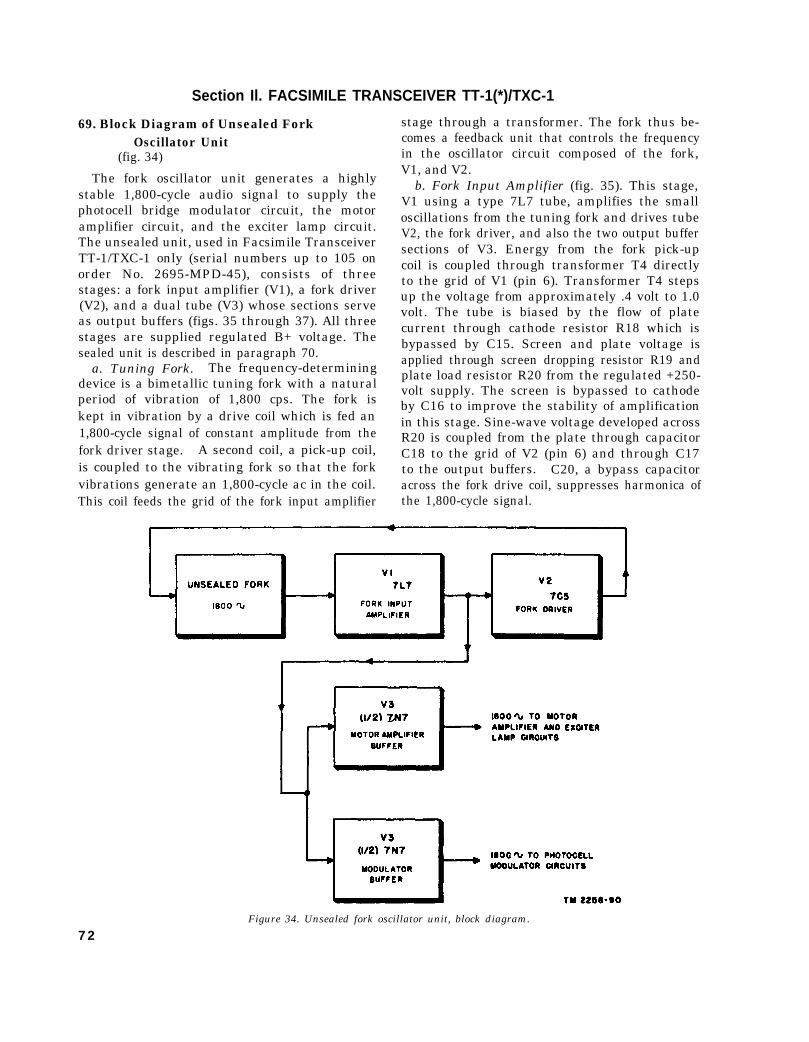
Section Il. FACSIMILE TRANSCEIVER TT-1(*)/TXC-1
69. Block Diagram of Unsealed ForkOscillator Unit
(fig. 34)
The fork oscillator unit generates a highlystable 1,800-cycle audio signal to supply thephotocell bridge modulator circuit, the motoramplifier circuit, and the exciter lamp circuit.The unsealed unit, used in Facsimile TransceiverTT-1/TXC-1 only (serial numbers up to 105 onorder No. 2695-MPD-45), consists of threestages: a fork input amplifier (V1), a fork driver(V2), and a dual tube (V3) whose sections serveas output buffers (figs. 35 through 37). All threestages are supplied regulated B+ voltage. Thesealed unit is described in paragraph 70.
a. Tuning Fork. The frequency-determiningdevice is a bimetallic tuning fork with a naturalperiod of vibration of 1,800 cps. The fork iskept in vibration by a drive coil which is fed an1,800-cycle signal of constant amplitude from thefork driver stage. A second coil, a pick-up coil,is coupled to the vibrating fork so that the forkvibrations generate an 1,800-cycle ac in the coil.This coil feeds the grid of the fork input amplifier
stage through a transformer. The fork thus be-comes a feedback unit that controls the frequencyin the oscillator circuit composed of the fork,V1, and V2.
b. Fork Input Amplifier (fig. 35). This stage,V1 using a type 7L7 tube, amplifies the smalloscillations from the tuning fork and drives tubeV2, the fork driver, and also the two output buffersections of V3. Energy from the fork pick-upcoil is coupled through transformer T4 directlyto the grid of V1 (pin 6). Transformer T4 stepsup the voltage from approximately .4 volt to 1.0volt. The tube is biased by the flow of platecurrent through cathode resistor R18 which isbypassed by C15. Screen and plate voltage isapplied through screen dropping resistor R19 andplate load resistor R20 from the regulated +250-volt supply. The screen is bypassed to cathodeby C16 to improve the stability of amplificationin this stage. Sine-wave voltage developed acrossR20 is coupled from the plate through capacitorC18 to the grid of V2 (pin 6) and through C17to the output buffers. C20, a bypass capacitoracross the fork drive coil, suppresses harmonica ofthe 1,800-cycle signal.
Figure 34. Unsealed fork oscillator unit, block diagram.
7 2

c. Fork Driver (fig : 36). This stage (V2), usinga type 7C5 tube, amplifies the output of V1 andsupplies feedback energy to the drive coil whichkeeps the fork vibrating. One of the requirementsfor frequency stability is 8 constant output fromthis stage to the fork drive coil. The grid isdriven so hard that variations in amplitude atthe input have practically no effect on the output.The output from the plate of V1 is coupled to thegrid of V2 (pin 6) through C18, with R23 servingas the grid return. Cathode resistor R24 andvariable resistor R25 are left unbypaseed toprovide degenerative feedback in this stage,giving a stabilizing effect on the output. ResistorR25 is variable to permit minor adjustments infrequency of the fork oscillator to compensatefor extreme variations in temperature, or changesin value of circuit components. The plate andscreen are connected together for triode operation.Plate voltage is applied through plate load resistorR26 from the regulated +250-volt supply. Theoutput voltage developed across R26 is coupledback to the fork drive coil through capacitor C19.
d. Fork Output Buffer (fig. 37). This stage(V3), using a type 7N7 dual triode, consists of twobuffer amplifiers fed by the fork input amplifierV1, and supplies an 1,800-cycle signal to themotor amplifier stage V4, the exciter lamp ampli-fier circuit in Power Supply PP-86(*)/TXC-1,and the photocell bridge modulator circuit (fig.
48). The buffer action prevents load variationsfrom affecting the fork oscillator.
(1)
(2)
Motor amplifier buffer. Pins 2, 3, and 4of tube V3 comprise the motor amplifierbuffer. The grid receives 1,800-cycleenergy from the plate of V1 throughcoupling capacitor C17 and limitingresistor R21. Resistor R27 serves asthe grid return and the grid is bypassedfor high frequencies by C21. Cathoderesistor R28 is left unbypassed to pro-vide degeneration. Plate voltage is ap-plied to pin 3 from the regulated +250-volt supply through plate load resistorR23. Output from the plate is coupledthrough C23 to the motor amplifierdriver stage (V4) via the MOTORJACK. Capacitor C23 also couples1,800-cycle energy to the exciter lampamplifier circuit in Rectifier Power UnitPP-86(*)/TXC-1 through pin 9 ofplug P1 . A connection from C23 tosection 3 of selector switch S1 short-circuits the 1,800-cycle supply to themotor circuit and the exciter lampcircuit when the switch is in the STAND-BY position.Modulutor buffer. Pins 5, 6, and 7 oftube V3 comprise the modulator buffer.The grid also receives 1,800-cycle energy
Figure 35. Fork input amplifier, unsealed fork oscillator unit.
73

Figure 36. Fork driver, unsealed fork oscillator unit.
from the plate of V1 through couplingcapacitor C17 and limiting resistor R22.Resistor R30 is the grid resistor, and thegrid is bypassed for high frequenciesby C22. Plate voltage is applied topin 6 from the regulated +250-voltsupply through plate load resistor R31.Output from the plate is applied to thephotocell bridge modulator circuitthrough blocking capacitor C24 andoutput coupling transformer T5. Theoutput coupling circuit includes a low-pass filter which eliminates harmonics ofthe 1,800-cycle frequency and deliversa sine-wave output to the modulator.Components of this low-pass filter in-clude hf shunt capacitors C25 and C26,an audio choke, a capacitor, and anoutput transformer. A connection tosection 2 of selector switch S1 short-circuits the input of T5, removing 1,800-cycle energy from the photocell circuitwhen the selector switch is in theSTANDBY, RECORD PHOTO, orRECORD DIRECT position.
Figure 37. Output buffers, unsealed fork oscillator unit.
74
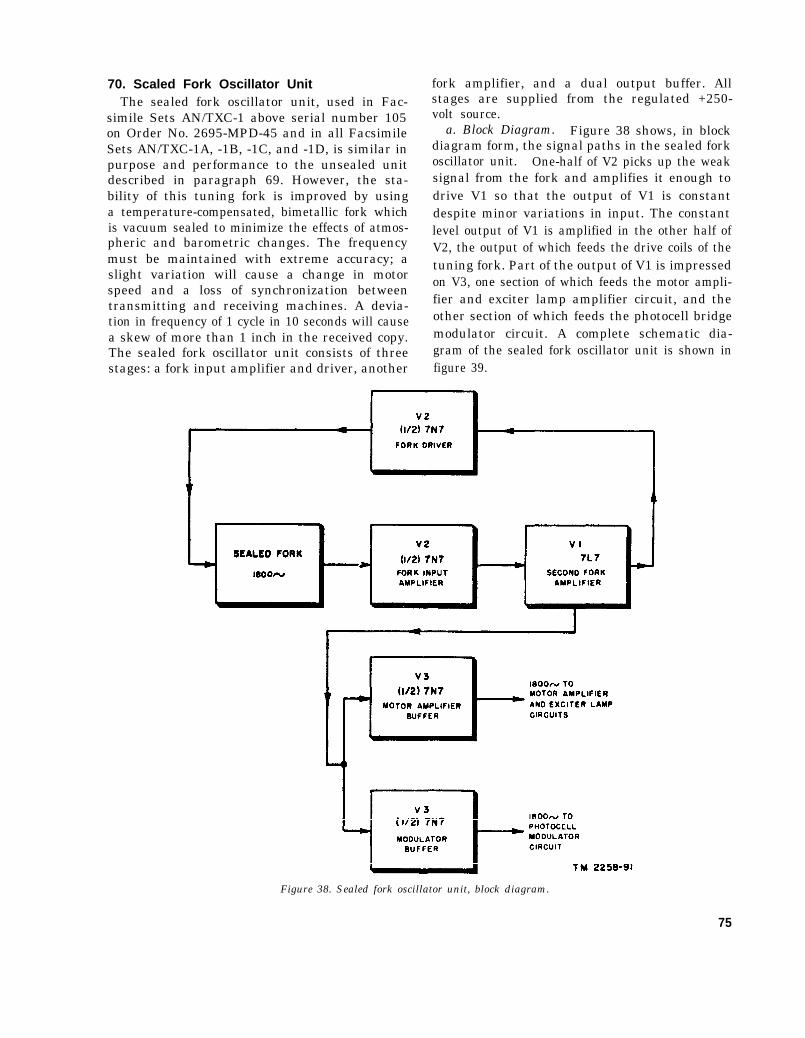
70. Scaled Fork Oscillator UnitThe sealed fork oscillator unit, used in Fac-
simile Sets AN/TXC-1 above serial number 105on Order No. 2695-MPD-45 and in all FacsimileSets AN/TXC-1A, -1B, -1C, and -1D, is similar inpurpose and performance to the unsealed unitdescribed in paragraph 69. However, the sta-bility of this tuning fork is improved by usinga temperature-compensated, bimetallic fork whichis vacuum sealed to minimize the effects of atmos-pheric and barometric changes. The frequencymust be maintained with extreme accuracy; aslight variation will cause a change in motorspeed and a loss of synchronization betweentransmitting and receiving machines. A devia-tion in frequency of 1 cycle in 10 seconds will causea skew of more than 1 inch in the received copy.The sealed fork oscillator unit consists of threestages: a fork input amplifier and driver, another
fork amplifier, and a dual output buffer. Allstages are supplied from the regulated +250-volt source.
a. Block Diagram. Figure 38 shows, in blockdiagram form, the signal paths in the sealed forkoscillator unit. One-half of V2 picks up the weaksignal from the fork and amplifies it enough todrive V1 so that the output of V1 is constantdespite minor variations in input. The constantlevel output of V1 is amplified in the other half ofV2, the output of which feeds the drive coils of thetuning fork. Part of the output of V1 is impressedon V3, one section of which feeds the motor ampli-fier and exciter lamp amplifier circuit, and theother section of which feeds the photocell bridgemodulator circuit. A complete schematic dia-gram of the sealed fork oscillator unit is shown infigure 39.
Figure 38. Sealed fork oscillator unit, block diagram.
75

b. Fork Input Amplifier Fork Driver (fig. 39).Dual triode tube V2 (7N7) serves as the fork inputamplifier and fork driver.
(1)
(2)
Fork input amplifier. Pins 2, 3, and 4comprise the fork input amplifier whichis fed 1,800-cycle energy generated in thepick-up coil by the vibrating fork. Re-sistor R302 is the unbypassed cathode re-sistor. Plate voltage is applied to pin 3from the regulated +250-volt supplythrough plate load resistor R301. Theoutput developed across the resistor iscoupled to the grid (pin 6) of the secondfork amplifier V1 (7L7) through couplingcapacitor C304.Fork driver. Pins 5, 6, and 7 comprise thefork driver. Input to the grid (pin 5) isreceived from the plate of V1 throughcoupling capacitor C303 and series re-sistor R305. Limiting resistor R305 andgrid resistor R306 serve, as a voltagedivider for the input to this section ofV2, Regulated +250 volts is suppliedthrough plate load resistor R307. Out-put from the plate is coupled throughC301 to the drive coil which keeps thefork oscillating. The cathode circuitconsists of two unbypassed resistors:fixed resistor R303 and variable resistorR304. Adjust R304 to compensate forminor changes in the frequency of thefork.
c. Second Fork Amplifier (fig. 39). Second forkamplifier V1 (7L7) is an amplifying link in theoscillator circuit composed of the fork, the inputamplifier, the second fork amplifier, and the forkdriver. The grid (pin 6) is fed from the plate(pin 3) of V2 through coupling capacitor C304.The grid voltage is developed across resistor R313.Cathode resistor R310 is bypassed by C306.Screen voltage is supplied through dropping re-sistor R311 and the screen is bypassed to cathodeby C305. The plate load resistor is R312 and the1,800-cycle output from the plate (pin 2) is coupledto the fork driver through C303 and limiting re-sistor R305, Part of the output of V1 is appliedto the dual buffer output stage V3 through limitingresistor R314.
d. Fork Ooutput Amplifier (fig. 39). The forkoutput stage V3 is a 7N7 dual triode tube. It con-sists of two buffer amplifiers, fed by second forkamplifier V1. This tube supplies an 1,800-cyclesignal to motor amplifier stage V4, the exciter
76
lamp amplifier circuit, and the photoed bridgemodulator circuit.
(1) Motor amplifier buffer. Triode section 5,6, and 7 of V3 is the motor amplifierbuffer. Its grid receives 1,800-cycleenergy from the plate circuit of V1through coupling capacitor C303 andlimiting resistor R314. The grid resistoris a combination of R315 and R318, withthe grid of the second section of V3 fedfrom a tap between these resistors.Capacitor C310 is an hf bypass for thegrid. Resistor R316 is the unbypassedcathode resistor. The signal at the platedeveloped across load resistor R308 iscoupled through C302 to motor ampli-fier stage V4 via the MOTOR JACKand control switch S4, and also to theexciter lamp amplifier circuit of RectifierPower Unit PP-86(*)/TXC-1.Note. In Facsimile Transceivers TT-1D/
T X C - 1 , T T - 1 E / T X C - 1 , a n d T T - 1 F / T X C -1, the motor amplifier buffer output is cou-pled to motor amplifier stage V4 throughthe motor speed control switch S4 permittingselection of either the 900-cycle output of themultivibrator (half-speed operation), or the1,800-cycle fork unit output. The selectedoutput is applied to the grid of V4 throughMOTOR JACK J6. In Facsimile TranceiverTT-1B/TXC-1, a connection to IIIR of selectorswitch S1C short-circuits the 1,800-cycle motorcircuit and exciter lamp supply when the selectorswitch and the STANDBY-MON-TALK switchare both at STANDBY. In Facsimile Trans-ceiver TT-1C/TXC-1, a connection to the frontof IIIR of selector switch S1C opens the B+circuit in the motor lead, and the connection tothe back of contact IIIR of the selector switchshort-circuits the 1,800-cycle exciter lamp circuitsupply when the selector and STANDBY-MON-TALK switches are at STANDBY. (Refer tofigure 167.) In Facsimile Transceivers TT-1D/TXC-1, TT-1E/TXC, and TT-1F/TXC-1 themotor is stopped by short-circuiting to groundthe grid of motor amplifier tube V4 through thecontacts of the STANDBY-MON-TALK switchand section 6 of the selector switch when bothswitches are operated at the STANDBY position.The exciter lamp supply is short-circuited toground through section 2 with the selector switchat STANDBY.
(2) Modulator buffer. Triode section 2, 3, and4 of V3 is the modulator buffer. Its grid(pin 4) receives the 1,800-cycle energydeveloped across R318, as explained in(1) above. Resistor R317 is the unby-passed cathode resistor. The plate

Figure 39. Sealed fork oscillator unit, schematic diagram.
circuit energy developed across load RECORD PHOTO or the RECORDresistor R309 is coupled through C309 DIRECT position in Facsimile Trans-to the low-pass filter and output trans- ceiver TT-1/TXC-1 (also in the STAND-former T5. Capacitor C308 across the BY position in Facsimile Transceiversinput and C307 across the output and T5 TT-1A/TXC-1 through TT-F/TXC-1).form part of a filter network whichreduces the hf components of the signal. 71. Motor Amplifier Driver and Output Stages
A connection to section IIR of the selector (V4, V5, and V6)switch short-circuits the input and output (figs. 40-46)to T5. This connection removes the Stages V4, V5, and V6 amplify the 1,800-cycle1,800-cycle energy from the photocell signal supplied by the fork oscillator unit, andcircuit when the selector switch is in the furnish ac power to operate the synchronous
77

motor. Input to the motor amplifier stage V4is approximately 25 volts. The voltage acrossthe motor, however, may be as high as 1,000 volts.
a. Motor Amplifier Driver.(1) Facsimile Transceivers TT-1/TXC-1 and
TT-1A/TXC-1 (fig. 40). The 1,800-cycle signal of the fork oscillator unit isapplied to the grid of the motor amplifierdriver stage V4 (7C5). This signal isapplied through terminal 5 of the forkoscillator terminal board through MO-TOR JACK J6 and is applied to avoltage divider consisting of R34, R35,and R36. Normally, the junction be-tween resistors R35 and R36 is shortedto ground so that R36 is out of the cir-cuit. The voltage across R35 is appliedto the tube control grid (pin 6). Duringthe phasing operation, however, R36becomes part of the voltage divider, andthe voltage to the grid of tube V4 isincreased. Increasing the input to V4results in increasing the drive on parallelmotor amplifier tubes V5 and V6, fur-nishing additional power to the synchro-nous motor. During the phasing oper-ation, the motor requires additionalpower because of the additional loadcreated by friction in the clutch mecha-
nism. During normal operation, withthe PHASE switch released, cathodecurrent of V4 flows through the phasingmagnet coil associated with trigger tubeV16 and also through the series resistorcombination, R66 and R67 (stage V13),which is in parallel with this coil. (Referto figures 48 and 49 and the over-allschematic diagrams of Facsimile Trans-ceivers TT-1/TXC-1 and TT-1A/TXC-1 (figs. 163 and 164).) The flow ofcurrent through the coil holds the arma-ture against the phasing magnet so thatit does not actuate the clutch mechanismused in the phasing operation. The flowof current through R67 adds to the bias oftube V13, which requires bias beyond thecut-off value. During the phasing opera-tion, the phasing magnet is disconnectedfrom the cathode circuit of V4, and thearmature is released. To compensatefor the removal of the phasing magnetcoil from the cathode circuit, resistor R40is connected in parallel with the seriescombination, R66 and R67, during thephasing operation. Capacitor C27 is thecathode bypass capacitor for tube V4.Screen and plate voltage is applied fromthe +450-volt supply through screen
Figure 40. Motor amplifier driver, facsimile transceivers, TT-1/TXC-1 and TT-1A/TXC-1.
78

(2)
dropping resistor R37 and through drop-ping resistor R38 and the primary wind-ing of class B driver transformer T1.The screen is not bypassed to ground.Facsimile Transceivers TT-1B/TXC-1 andTT-1C/TXC-1 (fig. 41). The motoramplifier driver circuit of FacsimileTransceiver TT-1B/TXC-1 or TT-1C/TXC-1 is similar to that described in(1) above for earlier models of the equip-ment, except that the grid and cathodecircuits of tubes V4 have been redesigned.Potentiometer R93 has been added to thegrid circuit of V4 so that proper adjust-ment may be made of the input to V4which, in turn, affects the drive of stagesV5 and V6. Resistor R93, located onMOTOR CURRENT meter M2, is ad-justed for proper motor current readingon this meter. Cathode current of V4 inFacsimile Transceiver TT-1B/TXC-1 orTT-1C/TXC-1 flows through the seriescombination of R66, control R97, andR67 of V13 in parallel with the phasingmagnet coil. Refer to paragraph 75 fordetails of V13 cathode circuit.
Note. The value of R66 is changed from 1,500ohms to 750 ohms in the motor amplifier driverstage of Facsimile Transceivers TT-1B/TXC-1and TT-1C/TXC-1 to compensate for the ad-dition of R97 to the cathode circuit of V13.
(3) Facsimile Transceivers TT-1D/TXC-1,TT-1E/TXC-1 and TT-1F/TXC-1 (fig.42). The motor amplifier driver circuitof Facsimile Transceivers TT-1D/TXC-1, TT-1E/TXC-1, and TT-1F/TXC-1(fig. 42) is the same as that of the 1Band 1C model transceivers, except for thefollowing changes which allow for a 900-cps signal at half-speed operation:
(a) Speed control switch (30RPM-60RPM), S4, in series with the 1,800-cps fork output to V4, and a multi-vibrator-t ype oscillator have beenadded. In the 60RPM position, the1,800-cps fork output is coupled di-rectly to the grid of V4 throughMOTOR JACK J6. For half-speedoperation of the scanning drum(30RPM), the 1,800-cps fork signallocks in the 900-cps multivibrator(V26, 7N7), the output of which isapplied to the grid of V4 throughMOTOR JACK J6.
(b) Capacitor C62 has been added to theplate circuit of V4 as an ac bypass.
(c) Capacitor C61 has been added betweenR34 and R93 to ground to improve the900-cps waveshape. To stop the motorduring standby periods, the grid of V4(pin 6) is short-circuited to ground
Figure 41. Motor amplifier driver, Facsimile Transceivers TT-1B/TXC-1 and TT-1C/TXC-1.79

Figure 42.
80

Figure 43. Multivibrator and motor amplifier driver Facsimile Transceiver TT-1F/TXC-1.
through the contacts of STANDBY- is common to both circuits. The motorMON-TALK switch S5 and selector current is a series of dc pulses that reoccurswitch S1 when both are operated to 1,800 times per second, since tubes V5 andthe STANDBY positions. V6 conduct only on the positive half-
b. Motor Amplifier Output Stage (figs. 44 through cycles of the 1,800-cycle input wave.46). In unmodified Facsimile Transceivers TT-1/ Choke T6 is not a part of the series-TXC-1 and TT-1A/TXC-1 (fig. 44), V5 and V6 resonant circuit; its ac impedance is highare type 6AC5GT/G tubes (type 1635 tubes when and it may be considered a device forthese units are modified in accordance with MWO shunt-feeding stages V5 and V6. Volt-SIG 11-2258-2). Refer to a(2) above and figure age across the synchronous motor wind-38. Tubes V5 and V6 are connected in parallel in ing and across T6 is approximately equalall models of the equipment and serve as single- and may rise as high as 1,000 volts.ended, zero-bias, Class B, power amplifier tubes Capacitor C30, by limiting transients,whose output drives the synchronous motor. prevents high peak voltages that might
(1) Facsimile Transceivers TT-1/TXC-1 andTT-1A/TXC-1 (fig. 44). Input to thegrids (pin 5) of V5 and V6 is applied fromV4 through transformer T1. The platecircuit of V5 and V6 consists of twoparts; a dc circuit to supply plate currentto the tubes and a series-resonant circuitat 1,800 cycles to power the motor. Thedc circuit consists of the synchronousmotor winding and choke T6. Theseries-resonant circuit consists of twoseries capacitors, C28 and C29, and thesynchronous motor winding, which isshunted by capacitor C30 to limit tran-sients. The synchronous motor winding
break down insulation if the motorwinding. In Facsimile TransceiverTT-1A/TXC-1, MOTOR FUSE F1 hasbeen added in the plate circuit of tubesV5 and V6. Capacitor C31 preventsarcing at the START switch contacts.Normally, the +450-volt circuit to theplates of V5 and V6 is completed throughthe START switch contacts, but whenthe START switch is operated to ener-gize the separate start windings, thesynchronous winding of the motor is dis-connected and the plates of V5 and V6are not energized.
81

Figure 44. Motor amplifier output stage, facsimile
(2) Facsimile Transceivers TT-1B/TXC-1and TT-1C/TXC-1 (fig. 45). Thesemodels operate the same as FacsimileTransceivers TT-1/TXC-1 and TT-1A/TXC-1 except for the following changes:
(a)
(b)
Bypass capacitor C31 in parallel withresistor R95 is placed across MOTORFUSE F1. MOTOR CURRENTmeter M2 indicates necessary adjust-ments of the motor current.Series resistor R39 limits the motor cur-rent, and bypass capacitor C60 keepsthis part of the circuit at ac groundpotential. A connection from R39 toSTART switch S4 stops the motor inFacsimile Transceiver TT-1C/TXC-1when selector switch (S1) is operatedto the STANDBY position. Thisconnection is made through the frontsection of S1, disconnecting the +450-volt supply from the motor circuitwhen the selector switch is operated tothe STANDBY position.
Transceivers TT-1/TXC-1 and TT-1A/TXC-1.
(3)
(4)
Facsimile Transceivers TT-1D/TXC-1.TT-1E/TXC-1, and TT-1F/TXC-1 (fig.46). In Facsimile Transceivers TT-1D/TXC-1, TT-1E/TXC-1, and TT-1F/TXC-1, MOTOR CURRENT meter M2is in the cathode circuit instead of theplate circuit of the motor amplifier outputstage. The plate circuit is modified sothat when the 30RPM-60RPM speedchange switch, S4, is in the 60RPMposition, C28 and C29 in series are acrossT6 for 1,800-cycle operation of the syn-chronous motor. When S4 is in the30RPM position, C28 and C29 in seriesare across the synchronous motor andT6 is shorted for 900-cps operation of themotor.Facsimile Ttransceiver TT-1F/TXC-1 (fig.46). In this model of the transceiver,capacitor C69 has been added to preventinterned arcing in motor amplifier tubesV5 and V6 by reducing peak voltages inthe 60RPM position.
82

Figure 45. Motor amplifier output stage, Facsimile Transceivers TT-1B/TXC-1 and TT-1C/TXC-1.
72. Multivibrator(V26 in Facsimile TransceiversTT-1D/TXC-1, TT-1E/TXC-1, andTT-1F/TXC-1 only)(figs. 42 and 43)
Tube V26 operates as a multivibrator. In thiscircuit, a portion of the output of one section of the7N7 tube is fed into the input circuit of the othersection. While one section conducts, the other sec-tion is cut off. The fork unit 1,800-cps output isfed to the plates of the 7N7 through C65 and R99.The values of C66, C67, R103, and R104, togetherwith the internal capacitances of the tube, deter-mine the frequency and rate at which each sectionconducts. The output is taken from the plate(pin 3) through C64. The multivibrator naturaloutput (output without synchronization signal) isslightly less than 900 cps; the 1,800-cps signallocks it at exactly 900 cps. Switch S4 selectseither the multivibrator output or the fork unitoutput directly and applies it through MOTOR
JACK J6 to the grid of motor amplifier drivertube V4.
73. Synchronous Motor
a. General. The synchronous motor in FacsimileTransceiver TT-1(*)/TXC-1 is held at a constantspeed of 60 rpm by the 1,800-cycle power suppliedby the plate circuit of motor amplifier outputtubes V5 and V6. A worm gear on the motorshaft is meshed with a gear which drives the leadscrew at 60 rpm through the clutch mechanism.The motors originally used in Facsimile Trans-ceivers TT-1/TXC-1 and TT-1A/TXC-1operated on 9-volt, 60-cps, ac, which was suppliedby Rectifier Power Unit PP-86/TXC-1. Thesemotors have been replaced with 115-volt acoperated motors, and the circuitry of the trans-ceiver and rectifier unit has been modified accord-ing to MWO SIG 11-2258-2. Facsimile Trans-ceivers TT-1B/TXC-1 through TT-1F/TXC-1contain motors that operate on 115-volt, 60-cps.
83

Figure 46. Motor amplifier outstage, Facsimile Transceivers TT-1D/TXC-1, TT-1E/TXC-1, and TT-1F/TXC-1.
ac. Operation of the motors is similar in allmodels of the equipment.
b. Stating Circuit. The motor contains aseparate starting coil in Facsimile TransceiversTT-1/TXC-1 through TT-1C/TXC-1 and asynchronous coil. The start section of the motoris a capacitor-start induction type which operateson 115-volt, 60-cps, ac. Pressing the STARTbutton (START-PHASE switch S3 on FacsimileTransceivers TT-1D/TXC-1, TT-1E/TXC-1,and TT-1F/TXC-1) disconnects the synchronousmotor winding and applies 115-volt ac to thestart winding. This voltage is brought up fromthe primary terminals of power transformer T11in the power unit through terminals 2 and 4 ofthe Jones plug and the contacts of the, startingswitch. The switch is held in the START position
84
until the drum speed rises above 60 rpm (3 to 5revolutions of the drum should be sufficient);then the switch is released. Note that the ca-pacitor winding of the start motor is in the circuitat all times. This winding also furnishes part ofthe power for the motor while it is running atsynchronous speed, but the major part of thepower is developed by the synchronous motor,which also controls the speed. Because thiscapacitor winding is in the circuit at all times,it is possible for this motor to run at a nonsyn-chronous speed. The operator must guard againstoperating the transceiver with the motor runningat a nonsynchronous speed. An 1,800- or 900-cycle tone from the motor laminations is the bestassurance that the motor is running at synchronousspeed.

74. Photocell Circuit(figs. 47,48, and 49)
Photocell tube V24 is the heart of the photocellbridge modulator circuit, which is used only ontransmitting. Tube 1645 is used as the photocellin Facsimile Transceivers TT-1/TXC-1 throughTT-1C/TXC-1. Tube 5652 is used as the photo-cell in Facsimile Transceivers TT-1D/TXC-1,TT-1E/TXC-1, and TT-1F/TXC-1. The photo-cell and its associated circuit (fig. 47,48, and 49)cause amplitude modulation of the 1,800-cycle signalsupplied from the fork oscillator unit. Amplitudemodulation follows the lights and shadows onthat portion of the transmitted copy beingscanned. After modulation of the 1,800-cyclesignal is accomplished in the photocell bridgemodulator circuit, the modulated signal is fed tothe grid (pin 6) of V10, the first signal amplifier.Tube V10 and the following signal amplifiers notonly amplify the modulated signal, but use aseries of differentiating circuits (small couplingcapacitors and large grid resistors) to removeundesirable low-frequency signal componentsgenerated in the modulator circuit. Photocelltube 5652 in Facsimile Transceivers TT-1D/TXC-1, TT-1E/TXC-1, and TT-1F/TXC-1 per-mits the use of larger values of coupling capacitorsthan photocell tube 1645, which was used inprevious models. The circuit that uses tube 5652is inherently balanced for the modulating fre-quency, and therefore requires no discriminationagainst low frequencies in its amplifier strip asrequired in previous models.
a. Simplified Bridge Modulator Circuit. Asimplified equivalent of the photocell bridge
Figure 47. Simplified bridge modulator circuit.
modulator circuit is shown in figure 47. In thesimplified circuit, the 1,800-cycle carrier signalfrom the fork oscillator unit is fed to points A andC of the resistance-capacitance bridge. Outputfrom the bridge is the voltage developed acrossR50, between points D and B. This voltage isthe grid to cathode or input voltage of V10. Asmall capacitance (Ct) exists between the cathodeand active anode of V24, and this is effectivelybalanced out by the neutralizing, capacitance(Cn), which is the capacitance existing betweenthe cathode and the second or neutralizing anodewithin the photocell. When the bridge is per-fectly balanced, there is no output of 1,800-cyclesignal to be applied to V10; but when increasedlight shines on the photocell, it causes increasedelectron emission from the cathode, producing aresistive unbalance of the bridge and a greater1,800-cycle signal.
b. Optical System. The light that reaches thephotocell can be determined at any instant by theshade (from white to black) of the small area oftransmitting copy being scanned. Light from theconstant source of illumination (the exciter lampshown in the transmitting block diagram (fig. 31))is concentrated onto a small portion of the copyby the condenser lens system. The illuminatedarea is approximately the size of the filament inthe exciter lamp. The objective lens focuses animage of the illuminated area of copy onto ascreen having a small hole or aperture that permitsonly the light from an area approximately oneninety-sixth of an inch square to pass onto thephotocell in back of the aperture. As the drumand copy move during transmission of a picture,each scanned element of the picture reflects adifferent amount of light back to the photocell.The photocell and bridge modulator circuit changeeach level of light into its equivalent electricalsignal.
c. Schematic Diagram:(1) Facsimile Transceivers TT-1/TXC-1
through TT-1C/TXC-1 (fig. 48). Theoutput of the bridge (the voltage across,R60) is a varying dc signal that consistsof the keying or modulating frequencywhich is superimposed on the 1,800-cyclecarrier frequency. This varying dc sig-nal is always of such polarity that thegrid end of R50 is positive with respect tothe other end. This is caused by the in-creased emission from the photocell whenincreased light strikes it. The conven-
85

Figure 48. Photocell bridge modulator circuit of Facsimile Transcievers TT-1/TXC-1 through TT-1C/TXC-1.
tional modulation envelope, consistingof the 1,800-cycle signal varied in ampli-tude both above and below the zeroaxis, first appears in a distorted form atthe grid of stage V10.
(a)
86
Resistor networks. Between points Aand C, figure 48, where the unmodu-lated 1,800-cycle carrier signal isapplied, are two resistor networks; oneconsists of R41, R42, and R43 in seriesand the other consists of R44, R45,and R46 in series. Resistors R47 andR48 are in series across R45. Thefirst of these networks includes variableresistor R42, which serves as a neutral-izing control and is used in balancingout the capacitive effect of the photo-cell. Its effect on the circuit is the sameas making Cn (fig. 47) variable. ResistorR42 is an alignment control and is lo-cated beneath the chassis of FacsimileTransceivers TT-1/TXC-1 throughTT-1B/TXC-1 (figs. 128 and 129).In Facsimile Transceiver TT-1C/TXC-1, R42 is located on the floatingpanel behind the DB METER. Thiscontrol is used to set the proper valueto balance out the capacitive effect ofthe photocell when the photocell ischanged; it is not used as an operatingcontrol. Capacitor C58 provides ca-
(b)
pacitive reactance to ground for theslide arm of R42, thereby permittingclose adjustment of the null point.Variable resistor R45 (in the secondnetwork across the input of the bridge)is the CONTRAST control, a frontpanel operating control used in settingthe original contrast range at thefacsimile transmitter. This controlmay be adjusted to balance the bridgeon either maximum light (positivetransmission; minimum signal onwhite, maximum on black) or onminimum light (negative transmis-sion; minimum signal on black, maxi-mum on white).Other components. Resistors R47 andR48 are used in place of the proper tapon CONTRAST control R45; theyserve merely to keep point D electri-cally at a predetermined relationshipwith respect to R45. Resistor R49,which may be shunted by R49A, R49B,or R49C, or combinations thereof, is aportion of a voltage divider betweenthe regulated B+ voltage and ground.This divider keeps both anodes of thephotocell at a slight positive potential(.3 to .6 volt) with respect to the photo-cell cathode. This bias extends thelinear portion of the photocell curve

Figure 49. Photocell bridge modulator, Facsimile TranseiversTT-1D/TXC-1, TT-1E/TXC-1, and TT-1F/TXC-1.
(2)
and makes possible the use of an in-creased 1,800-cycle input into thebridge.
Facsimile Transceivers TT-1D/TXC-1,TT-1E/TXC-1, and TT-1F/TXC-1 (fig.49). A type 5652 tube is used as thephotocell in these units. Resistor R49is not used and the regulated +250 voltsis not needed since this tube operateslinearly without the injection of fixedbias. Capacitor C58 is not used sincethe null point can be closely adjustedin these models (because of the operatingcharacteristic of photocell tube 5652)with the slide arm of R42 connecteddirectly to ground. Resistor R50 (fig.52) is the grid resistor of V10, the highside connecting both to the cathode ofthe photocell and to the grid of V10.Its low potential side is returned toground through R47, R48, and R45,when selector switch S1 (section 3) is in theTRANSMIT or SET RANGE position.On other settings of the selector switch,the bridge circuit continuity is inter-rupted.
75. Signal Amplifiers (V10 through V14)(figs. 50 through 54)
Facsimile Transceiver TT-1(*)/TXC-1 has fivestages of signal amplification. Various stages areused for various functions, as determined by thesetting of the selector switch and as illustratedin figure 76. Tubes V10, V11, and V12 are ClassA signal amplifiers. The first half of V13 isoperated as a Class C threshold limiter and servesas a driver for V14, a Class B output amplifier.Tubes V10 and V11 are used for all functions,V12 on TRANSMIT and RECORD PHOTO,V13 on RECORD DIRECT, and V14 on RE-CORD DIRECT and RECORD PHOTO posi-tions. The use of V10, V11, and V12 in the talk-back circuit is explained in paragraph 78.
a. First Signal Amplifier (V10) (figs. 51 and 52).This stage is a high-gain pentode voltage ampli-fier, tube 7C7 (tube 5879 in Facsimile Trans-ceiver TT-1E/TXC-1 and TT-1F/TXC-1), bi-ased for Class A operation and used for both trans-mitting and receiving.
(1) Transmitting. With the selector switchat TRANSMIT or SET RANGE, thegrid of V10 is fed by the photocell bridge
87

(2)
88
Figure 50. Signal amplifiers used in various positions of selector switch, block diagram.
modulator circuit as explained in para-graph 74. Resistor R50 serves as thegrid resistor, across which the modulated1,800-cycle signal is developed and ap-plied to the grid. Cathode bias isdeveloped across R51 and filtered byC32. The screen is fed through R52and bypassed directly to the cathode byC33. Resistor R53 is the plate loadresistor. An amplified modulated 1,800-cycle signal is developed across thisresistor and applied to the grid of tubeV11 through output coupling capacitorC35. Resistor R54 and capacitor C34form a resistance-capacitance decouplingnetwork between the stage and the sourceof regulated B+ plate and screen volt-ages.Receiving. With the selector switch in therecording positions, the bridge modulatoris inactive. The control grid of V10 isconnected through R50 as a series resistorand S1 is connected to the arm on controlR60, that half of the dual GAIN controlwhich serves as an input gain controlacross the secondary of input trans-former T7 (figs. 163 through 169). In-put to the transceiver is either throughthis line-matching transformer (T7) from
the LINE binding posts through section1 of the selector switch, or to the highend of R60 from the LINE JACKthrough section 3 of the switch, depend-ing on the input connections in use (par.15d). The rest of the circuit of V10 isthe same for receiving as for transmitting.
b. Second Signal Amplifier (V11) (fig. 53). Thesecond signal amplifier is a pentode voltage am-plifier tube 7L7, biased for Class A operationand used without circuit changes for bothtransmitting and receiving. The input is fromstage V10 and its output feeds V12 through thetransmitting portion of the dual GAIN control(R59) and also both triode sections of the signalmeter amplifier (V13). The input signal (themodulated 1,800 cycles from V10) is appliedthrough C35 and across grid resistor R55 to thecontrol grid of V11. Capacitor C35 is a low valuecapacitor used to attenuate unwanted low-fre-quency signals from the previous stage. In Fac-simile Transceivers TT-1/TXC-1 through TT-1C/TXC-1, C35 is 100 micromicrofarad (µµf).Cathode bias for Class A operation is developedby current flow through cathode resistor R56,which is bypassed at audio frequencies by C36.In Facsimile Transceiver TT-1D/TXC-1, cou-pling capacitor C35 is increased to 5,100 µµf (thesame as C38) and grid resistor R55 to 470,000

Figure
Figure
51. First ssignal amplifier, Facsimile Transceivers TT-1/TXC-1 through TT-1D/TXC-1, schematic
52. First signal amplifier, Facsimile Transceivers TT-1E/TXC-1 and TT-1F/TXC-1, schematic
diagram.
diagram.
89

Figure 53. Second signal amplifier.
ohms, since the use of tube 5652 as a photocell in (1) Transmitting. With the selector switchthese models precludes the passage of undesired set in the TRANSMIT or SET RANGElow frequencies through the amplifier strip. In position, the control grid of V12 receivesFacsimile Transceiver TT-1E/TXC-1 and TT- the signal coupled from the plate of tube1F/TXC-1, capacitor C35 is 240 µµf. The cathode V11 through C39 and developed acrossof V11 is not bypassed; sufficient signal is im- R59, the transmitting half of the dualpressed on the grid of this tube because of the GAIN control. The slider on R59increased values of coupling capacitor C35 and selects the portion of voltage across thegrid resistor R55 to make it unnecessary to have resistor which is to be applied to theadditional gain by means of cathode bypassing. grid of V12. Resistors R61 and R62 inScreen current is supplied through screen resistor series constitute a voltage divider acrossR57, and the screen is bypassed to ground by the input circuit of V12. Half of theC37. Regulated plate voltage is applied through V12 grid voltage is applied from theR58, the plate load resistor. The amplified junction of R61 and R62 through capac-1,800-cycle signal developed across R58 is applied itor C41 to the grid of the meter amplifierthrough C39 to output GAIN control R59, and half of V13 (figs. 55 and 56). Tube V12through C38 to the grid circuit of the signal am- is biased by cathode current flowingplifier half of dual triode tube V13. through cathode resistor R63, which is
c. Third Signal Amplifier (V12) (fig. 54). The bypassed at audio frequencies by C40.third signal amplifier is a triode-connected, Class Transformer T2 is the output trans-A signal amplifier, using a 7C5 tube, which serves former for stage V12. Plate currentas the transceiver output amplifier on transmitting flows through the primary from the reg-and as a driver stage for V14 (Class B stage) on ulated +250-volt supply. Signal varia-photo recording. Tube V12 is in the facsimile tions at the plate of V12 cause signalsignal circuit only when the selector switch is in voltages to be induced in the twothe TRANSMIT, SET RANGE, or RECORD secondaries of T2. In the TRANSMITPHOTO position. The stage amplifies modulated position of the selector switch only,1,800-cycle signals in both transmitting and re- secondary No. 1 is connected to theceiving functions. The stage is also used in the LINE JACK, one side of which istalk-back circuit of Facsimile Transceivers TT- grounded through section IVL of the se-1A/TXC-1 through TT-1F/TXC-1.
90
lector switch, and secondary No. 2 is

(2)
Figure 54. Third signal amplifier.
connected to the LINE binding poststhrough sections IR and IL and attenu-ator resistors R84 and R85. In the setRANGE position of the selector switch,the LINE binding posts and the LINEJACK are disconnected, and secondaryNo. 1 is short-circuited and grounded.Receiving. When the selector switch isat any other position than TRANSMITor SET RANGE, the low side of R59(the output GAIN control) is un-grounded, removing its effectiveness as again control but still permitting V12 tobe fed by V11. Tube V12 serves as areceived signal amplifier only for photo-graphic recording. With the selectorswitch in RECORD PHOTO position,the plate circuit of V12 is establishedthrough the primary of transformerT2 and through section IVR of the selectorswitch. Secondary No. 2 of T2 is open-circuited, but secondary No. 1 of T2 isin the grid circuit of V14, the outputamplifier for recording. With the selec-tor switch in the RECORD DIRECTposition, the plate circuit of the record
direct amplifier (V13, section 5-6-7) iscompleted through the primary of trans-former T2 and section IVR of the selectorswitch, with secondary No. 1 of T2 con-nected to the grid circuit of V14.
d. Signal Meter Amplifier (V13) (figs. 55 and56). This stage uses dual-triode tube 7N7. Sec-tion 5-6-7 serves as the Class C RECORDDIRECT amplifier-driver stage which drivesstage V14. Pins 2, 3, and 4 serve as the meteramplifier, providing a vacuum-tube voltmeter cir-cuit for measuring input and output signal levelsin decibels.
(1) Record direct amplifier driver. Althoughthe grid (pin 5) of the first section of tubeV13 is fed a modulated 1,800-cycle signalat all times, the stage is operative onlywhen the selector switch is in the REC-ORD DIRECT position. The stage isoperated as a threshold limiter; that is,it is biased considerably beyond cutoffand prevents an output signal until theinput signal reaches a predeterminedlevel. This is advantageous in control-ling the signal used on direct recording.The grid (pin 5) is fed from the plate of
91

Figure 55. Record direct amplifier driver and meter amplifier, Facsmimile Transceivers TT-1/TXC-1 and TT-1A/TXC-1.
Figure 56. Record direct amplifier driver and meter amplifier, Facsimile TransceiversT T - 1 B / T X C - 1 t h r o u g h T T - 1 F / T X C - 1 .
92

V11 through coupling capacitor C38 andlimiting resistor R65. Resistor R65 isin the circuit to prevent the grid fromdrawing current when the plate circuit isnot energized; that is, when the selectorswitch is in some position other than inthe RECORD DIRECT position. Dur-ing operation of the stage, the grid is notfed sufficient signal to drive it positiveand cause grid current to flow throughgrid resistor R64. Bias for the stage(approx. 18 volts) is developed by theflow of cathode current in stage V13 andmotor amplifier stage V4. In FacsimileTransceivers TT-1/TXC-1 and TT-1A/TXC-1, V4 cathode current flowsthrough resistors R66 and R67. Thebias on V13 is the voltage developedacross R67. In Facsimile TransceiversTT-1B/TXC-1 through TT-1F/TXC-1,V4 cathode current flows through resis-tors R66, R67, and R97 (fig. 56). Thebias on V13 is the voltage developedacross R67 and that portion of poten-tiometer R97 which is in the V13 cathodecircuit. Control R97 can be adjustedfor best operation of the stage. Thecathode resistor is bypassed by capacitorC42. Only when the selector switch isin the RECORD DIRECT position isplate current supplied to this section ofV13 through section S1D of the selectorswitch and the primary of transformerT2, which now becomes the Class Bdriver transformer for stage V14.
(2) Meter amplifier. The grid (pin 4) of themeter amplifier tube, triode section 2, 3,and 4 of V13, is fed at all times by thevoltage across R62 in the grid circuit ofstage V12. Capacitor C41 is the inputcoupling capacitor and R68 is the gridresistor for this section of V13. TheDB METER, an ac meter with a self-contained copper-oxide rectifier, receivesits signal from the shunt-fed plate circuitof the stage. The plate is supplied fromthe regulated +250-volt supply throughplate load resistor R69. Capacitor C43couples the modulated 1,800-cycle signalfrom the plate to the meter through R70for the TRANSMIT and SET RANGEpositions of the selector switch and throughR71 for the RECORD PHOTO and
RECORD DIRECT settings of the se-lector switch. This meter is disconnectedin the STANDBY position of the selectorswitch.
e. Record Output Amplifier (V14) (fig. 57).The record output amplifier, V14 (type 1635), aClass B power stage, drives the recorder lamp onthe RECORD PHOTO setting of the selectorswitch, and drives the stylus on the RECORDDIRECT setting of the selector switch. Thesetwo outputs are plate circuit outputs A separate,cathode circuit output is taken during the phasingoperation (when the PHASE switch is operated)and is applied to cathode-driven pulse amplifierstage V15 (par. 74 and fig. 59). Stage V14 isdriven through secondary No. 1 of transformerT2 by stage V12 when the selector switch is in theRECORD PHOTO position and by stage V13 inthe RECORD DIRECT position. A type6AC5GT/G tube was originally used in FacsimileTransceivers TT-1/TXC-1 and TT-1A/TXC-1,but was replaced in these equipments with a type1635 tube (MWO SIG 11-2258-2) because of fre-quent failure.
(1) Record photo (fig. 57). Input to V14 fromsecondary No. 1 of T2 is applied to gridsNo. 4 and 5 in parallel. Plate voltageis applied from the regulated +250-voltsupply through the recorder lamp (E2)and resistor R94 in parallel (modifiedFacsimile Transceivers TT-1/TXC-1 andTT-1A/TXC-1 have resistor R94). Thestage is biased Class B, so that with nosignal input, the recorder lamp producesonly a slight glow. The recorder opticalsystem uses recorder lamp E2, tubeR1130B, which is a neon-filled lamp,capable of converting varying signal in-tensities into varying amounts of light.The lamp is mounted in a housing (A,fig. 121) which opens into an apertureplate and field lens at one end of a lensbarrel. On the other end of the barrelis an objective lens which focuses thelight passing through the aperture to asmall spot on the film or photographicpaper. The recording beam produces ex-posures in accordance with its intensity.
(2) Record direct (fig. 57). Input to V14 inthis position is applied from record directamplifier driver V13 through the selectorswitch. Plate voltage is supplied fromthe unregulated +450-volt supply
93

(3)
94
Figure 57. Record output amplifier, Facsimile Transceiver TT-1(*)/TXC-1.
through the primary of the stylus trans-former T3 and the selector switch. InFacsimile Transceiver TT-1E/TXC-1,resistor R106, and capacitor C68 areadded in series across the selector switch.One aide of the secondary is groundedand the stylus is connected to the highside through an rf suppressor composedof R73, R91, and C44. This suppressorreduces electrical interference from thespark. The audio output voltage causesa spark between the stylus and thegrounded metal drum of the transceiver,burning the white covering from theblack recording paper.Cathode circuit. In normal operation ofstage V14, the cathode is connected di-rectly to ground through contacts of thephasing switch. This permits normalzero-bias operation of the Class B stage.During phasing operations, however, re-sistor R72 is connected into the cathodecircuit of V14 and becomes a couplingresistor between stages V14 and V15.Phasing pulses from the transmitter aretransferred from the output of V14 to theinput of V15.
76. Automatic Stop Circuit (End-of-CopyLimit Switch)
(fig. 58)An automatic stop circuit is incorporated in
Facsimile Transceiver TT-1F/TXC-1 to switchthe amplified facsimile signal to ground and tostop the synchronous motor when the drum reachesthe end of its travel. The circuit operates in allpositions of the selector switch and has a lockingfeature when in the TRANSMIT, RECORDDIRECT, or RECORD PHOTO position. Thestop is intended to prevent unnecessary wear of thehalf nut threads if the machine is left unattendedat the end of a transmission. It prevents marringof the recorded copy by the stylus should theoperator move the drum to the right at the com-pletion of a transmission while the selector switchis in the RECORD DIRECT position and theincoming signal is still on. The circuit consists oflimit switch S8 which is operated by the drumwhen it reaches the end of its travel. It also con-sists of relay K1 which is energized by 115 voltsdc obtained by passing regulated dc voltage(RB+) through dropping resistors R109 andR110.
a. When the transceiver ia operated in theTRANSMIT position and the drum reaches the

Figure 58. Automatic stop circuit, Facsimile Transceiver TT-1F/TXC-1.
end of its travel, limit switch S8 closes. Thisenergizes relay K1. Contacts 5 and 6 open andbreak the tuning fork signal to the grid of themotor amplifier tube (V4). Contacts 3 and 4close and short the output signal to ground.Contacts 1 and 2 close to keep the relay energizedif the drum is moved away from the limit switch.
b. To de-energize relay K1 before the nexttransmission, the selector switch must be turnedto SET RANGE or STANDBY and the drummoved to the right away from limit switch S8.The relay coil is de-energized in these positionssince the path to ground from pin 2 of the relay isopened.
c. When the transceiver is operated in theRECORD PHOTO or RECORD DIRECT posi-tion, the automatic stop circuit functions in thesame manner. The synchronous drive motor isstopped and the signal to record output amplifierV14 is shorted to ground. To de-energize therelay for the next recording, the selector switchis turned to STANDBY and the drum is movedto the right to disengage it from limit switch S8.
77. Phasing Circuit (V15 and V16)The phasing operation is performed jointly by
the transmitting and receiving operator. Thetransmitting operator turns the selector switchof the transmitting transceiver to TRANSMITand causes the scanning system to scan thephasing ring on the scanning drum. A pulse,in the form of an abrupt increase or an abruptdecrease in the amplitude of the 1,800-cyclecarrier signal, is generated by the transmittereach time it scans the white spot on the darkphasing ring (once each second). The transmit-ting operator does not operate the phasing switchon his machine. The receiving operator phaseshis machine to the transmitting machine byturning the selector switch to RECORD PHOTOand by pressing the PHASE button. (In Fac-simile Transceivers TT-1D/TXC-1, TT-1E/TXC-1, and TT-1F/TXC-1, the operator phaseshis machine to the transmitting machine by press-ing the START PHASE switch toward PHASE.)
a. PHASE Switch. The receiver phasing circuit(fig. 59) is operative only when the PHASE
95

Figure 59. Pulse amplifier.
switch is pressed. Pressing this switch makesthe following circuit changes:
(1)
(2)
(3)
(4)
Removes the phasing magnet from thecathode circuit of V4, stopping the flowof holding current through the magnet.The magnet armature then engages thestop arm on the clutch, causing thereceiving drum to rotate slower thanthe transmitting drum.Substitutes R40 in the cathode circuit ofV4 to compensate for the removal of thephasing magnet (par. 71).Disconnects the short circuit across R36in the grid circuit of V4, providingincreased drive to V4 (par. 71).Disconnects the short circuit across R72,coupling stage V14 into stage V15.
b. Electrical Circuit. The phasing pulse re-ceived over the facsimile circuit is amplified bystages V10, V11, V12, and V14 of the receivingtransceiver, and is rectified by the combination
96
of tube V14 and the recorder lamp. The 1,800-cycle component is removed by a filter (C45, C46,C47, and R74) in the input circuit of V15. Thistube amplifies the pulse, which is applied to theinput of thyratron trigger tube V16. Each pulsecauses V16 to arc, pulling the armature to thephasing magnet and releasing the primary clutchstop arm. The transmitter sends the phasingpulse just as the stop arm on the transmittingmachine is passing the phasing magnet. Sincethe receiving stop arm is released by the phasingpulse at this same instant, the transmitting andreceiving transceivers are phased.
c. Pulse Amplifier (V16) (fig. 59). Stage V15uses a type 7L7 tube as a pulse voltage amplifierin an inverted circuit. When the PHASE switchis operated, the pulse voltage developed acrossR72 (cathode resistor of V14) is applied betweenthe cathode and the grid of V15. The cathodeof V15 is at signal input potential, and the gridis at ground potential for signal input. The

phasing pulse (a sudden decrease or increase inthe 1,800-cycle signal) is smoothed into a dcpulse by the filter action of 50-microfarad capaci-tor C45 across R72, C46 between cathode and grid,and C47 between plate and ground. ResistorR74 serves as the grid resistor. Screen current isfed through screen dropping resistor R75, whichis bypassed by C48. The dc pulse developedacross plate load resistor R76 is coupled to thegrid of trigger tube V16 through coupling capaci-tor C49. Both plate and screen are suppliedfrom the regulated +250-volt supply. Refer tofigures 74 and 75 for waveforms.
d. Trigger Tube (V16) (fig. 60). The triggertube is a gas-filled thyratron, type 884 connectedso that each phasing pulse applied to ita gridcauses the tube to arc and energize the phasingmagnet. When the PHASE switch on thetransceiver is operated, the normal holding cur-rent from the cathode circuit of tube V14 isremoved, permitting the magnet armature to en-gage the stop arm on the primary clutch. TubeV16 has a positive potential of 250 volts applieddirectly to ita plate from the regulated +250-voltsupply. In the absence of a phasing pulse, thecathode is approximately 57 volts positive withrespect to ground, being tapped onto the voltagedivider composed of R17 and R78 across theregulated +250-volt supply. Since the tube gridis at ground potential, there being no voltagedrop across grid resistor R77, the grid is effectivelynegative with respect to the positive cathode, andthe tube is nonconductive. Capacitor C50 ischarged 57 volts positive because, in series withthe phasing magnet coil, it is across cathode re-sistor R78. When a phasing pulse on the grid ofV16 causes the tube to arc, the voltage dropacross the tube and across R17 is suddenlyreduced to 16 volts, the characteristic voltagedrop across this tube when it arcs; then thecathode potential suddenly becomes 234 volts,increasing approximately 177 volts in a positivedirection. This sudden change in potential acrossC50 causes sufficient electron flow through thephasing magnet to attract the armature and releasethe stop arm on the clutch; but as soon as thecharge on capacitor C50 is equalized by the cur-rent flow through the phasing magnet, the im-pedance of the cathode circuit again becomesvery high (with R78 serving as a current-limitingresistor) and the tube arc is extinguished. Thenegative grid of the tube then resumes control,keeping the tube nonconductive and the phasing
magnet de-energized until the next phasing pulsearrives. Capacitor C49 and resistor R77 con-stitute a differentiating circuit, serving to sharpenthe peak of the useful positive pulse.
(1)
(2)
Phasing error. The phasing pulses aretransmitted at slightly different timeswhen transmitting for negative and posi-tive reception. When transmitting forpositive reception (maximum signal onblack), a positive voltage large enoughto make V16 arc is developed immedi-ately after scanning of the phasing spot.This is at the instant when the scanningchanges from the white of the phasingspot (minimum signal) to the black ofthe phasing ring (maximum signal).However, when transmitting for negativereception (maximum signal on white),the necessary positive voltage pulse isdeveloped at the very beginning of thescanning of the phasing spot. This isat the instant when the scanning changesfrom the black of the phasing ring (mini-mum signal) to the white of the phasingspot (maximum signal). Therefore, theexact phasing point of positive record-ing is displaced from the exact phasingpoint for negative recording by thelength of the phasing pulse (length ofthe phasing spot on the phasing ring).Correction of error. To divide this errorevenly, the dog trip arm is so positionedthat it splits the two pulses (positiveand negative) evenly on each side of thecenter. The error is then so small onboth positive and negative transmissionsthat no appreciable portion of the pictureis obscured by the image of the clampbar.
e. Clutch Operation (figs. 18, 19, and 20). Whenthe PHASE switch is operated, and before a phas-ing pulse arrives, the holding current normallyapplied to the phasing magnet from the cathodecircuit of V4 is removed. The phasing magnetarmature is released and stops the travel of thestop arm (fig. 18), which is friction driven by themotor through the primary clutch. The stop arm,on which the phasing operation actually is per-formed, normally drives the dog trip arm whichcauses the drum to rotate. However, once thePHASE switch is operated and the stop arm isheld stationary by the phasing magnet armature,the drum is driven at a slower rate by action of the
97

Figure 60.
secondary clutch, which permits intermittentslippage. During a part of each revolution, thedrum is driven by the secondary clutch, the drivebeing active only when the dog latch is engagedin the secondary clutch ring. During the restof each revolution, a cam operating on the doglatch disengages the dog latch from the secondaryclutch ring, permitting the slippage (fig. 19).When a phasing pulse from the transmitting sta-tion energizes the phasing magnet, the phasingmagnet armature is drawn to the magnet, thetravel of the stop arm is no longer impeded, andthe primary clutch resumes rotation. The firstphasing pulse may serve to phase the stop armto the transmitting drum correctly, althoughseveral are allowed. Once the correct phasing isestablished, additional phasing pulses pull thephasing magnet armature out of the way just asthe stop arm approaches it on each revolution.The PHASE switch then can be released. How-ever, the entire phasing operation is not completeuntil the stop arm actually engages the dog triparm (fig. 20). Only then is the receiving drum,as well as the stop arm, phased to the transmittingdrum. For this reason, the operator must allowa few extra revolutions for the stop arm to catchup with the dog trip arm and transfer the drumdrive from the secondary clutch to the primaryclutch before assuming that phasing is complete.
98
Trigger tube.
78. Talk-Back Circuit(figs. 61 and 62)
The talk-back circuit, only on Facsimile Trans-ceivers TT-1A/TXC-1 through TT-1F/TXC-1, iscontrolled by the STANDBY-MON-TALK switchS5) on the front panel. The circuit is operativeonly when the selector switch (S1) is in theSTANDBY position. When the STANDBY-MON-TALK switch is in the TALK position, theloudspeaker plugged into SPEAKER JACK J7becomes a magnetic microphone and transformsspeech sound waves into electrical currents, whichare transferred to the line through the speakertransformer, amplifier stages V10, V11, and V12,and output transformer T2 (figs. 51, 53, and 54).For reception of voice signals with the switch ineither the STANDBY or MON position, the sig-nal from the line is fed through input transformerT7, the GAIN control, amplifier stages V10, V11,and V12, and through the speaker transformer tothe speaker. The STANDBY-MON-TALKswitch makes the following circuit connections:
a. Standby.(1) The LINE binding posts are connected
to the primary of input transformer T7through S1, section 1, and S5.
(2) The LINE JACK is connected to thesecondary of input transformer T7through S1, section 3, and S5.

Figure 61. Talk-back circuit, STANDBY-MON-TALK switch S5 in TALK position, schematic diagram.
Figure 62. Talk-back circuit, STANDBY-MON-TALK switch S5 in STANDBY position, schematic diagram.
99

(3)
(4)
(5)
(6)
(7)
The slider on receiving GAIN control R60connects through S1, section 2, S5, andR50 to the grid of first signal amplifierV10.Tubes V10, V11, and V12 amplify the sig-nal and apply it through switch S1, sec-tion 4, to the primary of T2. SecondaryNo. 1 of T2 is connected through switchS1, section 4, and switch S5 to SPEAKERJACK J7.The 1,800-cycle signal from the fork oscil-lator unit to the motor amplifier circuitis grounded through the exciter lampand filament transformers, and the syn-chronous motor does not operate.Subparagraph (5) above does not applyto Facsimile Transceivers TT-1D/TXC-1, TT-1E/TXC-1, and TT-1F/TXC-1. In these models, the grid of V4is grounded through S1, section 6, andthe synchronous motor does not operate.The PHONES and RADIO RCVR jacks(J1 and J2), permanently connected inparallel across the primary of T7, pro-vide for voice reception when a radio cir-cuit is used.
b. MON (Monitor position). In this position ofthe STANDBY-MON-TALK switch, the sameconnections are completed as in the STANDBYposition, except that the 1,800-cycle supply to themotor amplifier circuit is not grounded, and themotor can operate.
c. TALK.(1)
(2)
(3)
(4)
(5)
100
The LINE binding posts are disconnectedfrom input transformer T7 and connectedto output transformer T2 (secondaryNo. 2), through S1, section 1, S5, and300-ohm dropping resistors R84 and R85,The LINE jack is disconnected from inputtransformer T7 and is connected to out-put transformer T2 (secondary No. 1)through S1, sections 3 and 4, and S5.
The receiving GAIN control R60 is dis-connected from the first signal amplifierV10. No GAIN control is used in thetalking end of the talk-back circuit.
The loudspeaker serves as a microphoneand is connected through SPEAKERJACK J7, switch S5, switch S1, section2, and resistor R50 to the grid of the firstsignal amplifier V10.Tubes V10, V11, and V12 amplify thesignal and apply it to the primary of
(6)
(7)
(8)
transformer T2 through switch S1, sec-tion 4. Secondary No. 1 is connectedthrough S1 section 4, S5, and S1 section 3to LINE JACK J5. Secondary No. 2 isconnected through S5 and S1 section 1to the LINE binding posts.
The 1,800-cycle signal from the fork unitis supplied to the motor amplifier circuit,and the motor can operate.The push-to-talk relay control circuit onthe CARBON MIKE jack is closed toput the transmitter on the air when aradio circuit is used.Resistor R98 (in Facsimile TransceiversTT-1B/TXC-1 through TT-1F/TXC-1only) is disconnected as a shunt acrossR92 and is shunted across the LINEJACK terminals.
79. B+ Voltage Regulators (V7, V8,V9, and V25)
(figs, 63, 64, and 65).
The B+ voltage regulator, located in FacsimileTransceiver TT-1(*)/TXC-1 (figs. 63-65), dropsthe 450-volt dc input from the rectifier power unitto regulated +250 volts for critical transceivercircuits.
a. Two triode-connectad voltage regulator out-put tubes (V7 and V8, type 7C5) (fig. 63) areconnected in parallel with their plates at +450-volt potential and their cathodes at +250-voltpotential. In this way, their plate cathode im-pedance forms a variable series dropping resistorto drop the +450 volts to +250 volts. The valueof this dropping resistor is automatically variedby varying grid bias of the tubes to provide aconstant output voltage. Tube V9, type 7L7, a pentode, control voltage amplifier tube amplifiesvoltage changes in the +250-volt supply and con-trols the grids of regulator tubes V7 and V8. Thegaseous voltage regulator tube (V25) in the cath-ode circuit of V9 provides a constant voltage drop(approx. 70 volts), serving as a reference level forstabilizing the +250-volt output. This tube istype R1160A or R1160B in Facsimile Trans-ceivers TT-1/TXC-1 and TT-1A/TXC-1 andtype 5651 in Facsimile Transceivers TT-1B/TXC-1 through TT-1F/TXC-1. The output voltagemay be stabilized anywhere between +240 and+255 volts, but once established, it will not varymore than 2 volts under normal operating condi-tions.

Figure 63. Voltage regulator output stage, RB+ circuit
b. To understand the functioning of the circuitin Facsimile Transceivers TT-1/TXC-1 and TT-1A/TXC-1, assume that the +250-volt output ofthe regulator suddenly changes to some highervoltage because of line or load changes. The gridbias on tube V9 (fig. 64) is the difference in poten-tial between the cathode and the grid of the tube.In thie circuit, that potential difference consistsof the difference between the voltage drop acrossV25 and the voltage drop across the parallel com-bination, R90 and R90A. This combination ispart of the voltage divider circuit which also in-cludes R89, and is across the regulated +250-voltoutput. However, the voltage drop across R90and R90A is opposite in polarity to that across V25when the cathode grid circuit is considered. Thevoltage drop across R90 and R90A changesapproximately one-third as much as the voltageof the +250-volt supply. The drop across V25 isconstant. Normally, the bias on V9 is about -3volts. When the output voltage rises slightlyabove 250 volts, the bias on tube V9 increases in apositive direction. More positive grid voltage
causes V9 to conduct more current, producing agreater voltage drop across plate load resistorR87. The voltage change at the plate of V9 is ina negative direction, and is greater in magnitudethan the voltage change in a positive direction onthe grid. This increased negative voltage at theplate of V9 is directly applied to the grids of V7and V8, causing their plate cathode impedanceto increase. This increase in impedance dropsthe regulated output voltage back to a normal250 volts.
c. Resistor R86 is the V9 screen resistor and isbypassed to ground by C56 to prevent oscilla-tion. Resistor R90A is in parallel with R90, andits value may be changed to adjust the value ofthe regulated output voltage. Capacitor C57bypasses R89 as a smoothing filter capacitor.Capacitor C55 serves as a smoothing filter capac-itor across the 450-volt input to the voltage regu-lator. Resistor R88 serves as a current limitingresistor in series with V25 to keep it operating inits normal range.
Figure 64. Control voltage amplifier, RB+ circuit, Facsimile Transceivers TT-1/TXC-1 and TT-1A/TXC-1.
101

d. The B+ voltage regulator circuit in Facsim- Potentiometer R96 is located on the regulated B+ile Transceivers TT-1B/TXC-1 through TT-1F/ voltmeter M3 (fig. 65), which is also a componentTXC-1 (fig. 65) operates in the same manner as only of Facsimile Transceivers TT-1B/TXC-1,that described above. However, potentiometer through TT-1F/TXC-1. The value of R88 hasR96 has been inserted into the grid circuit of been modified so that it still provides minimumstage V9 to permit easy control of the output stabilization current for the reference voltagevoltage and to eliminate the necessity of shunting regulator tube V25.R90 with R90A to obtain the correct voltage.
Figure 65. Control voltage amplifier, RB+ circuit, Facsimile Traneceivers TT-1B/TXC-1, TT-1C/TXC-1, TT-1D/TXC-1.TT-1E/TXC-1, and TT-1F/TXC-1.
Section Ill. RECTIFIER POWER UNIT PP-86(*)/TXC-1
80. Block Diagram(fig. 66)
The rectifier power unit serves four purposes:a. Provides unregulated B+ at 450 volts dc
and filament voltage at 6.5 v ac for operation ofthe transceiver for a normal source of 115-volt60-cycle ac.
b. Provides 115-volt 60-cycle ac for startingthe synchronous motor in Facsimile TransceiverTT-1(*)/TXC-1.
c. Provides closely regulated voltage for theexciter lamp (6 volts at 1,800 cycles) from a 1,800-cycle signal supplied by the fork oscillator unit.
d. Rectifier Power Unit PP-86E/TXC-1 alsoprovides 115 volts at 60 cps for the dust removalblower motor.
102
81. Power Supply Rectifier (V22)(fig. 67)
The high-voltage power supply rectifier (V22),located within Rectifier Power Unit PP-86(*)/TXC-1, furnishes +450-volt unregulated dc fortransceiver plate and screen circuits. The +450-volt, unregulated dc also is the source of voltagefor the voltage regulator (V7, V8, V9, and V25)located on the transceiver chassis (par. 80), whichfurnishes regulated +250 volts for critical trans-ceiver circuits. Rectifier V22, type 5Z2, is con-nected in a conventional full-wave rectifier cir-cuit. Transformer T11 changes the 115-volt acinput on the primary side to high voltage for theplates of V22, 5 volts for the filament of V22, 6.5volts for filaments of other tubes in the power

Figure 66. Rectifier power unit PP-86(*)/TXC-1, block diagram.
Figure 67. Rectifier power power supply, part of Rectifier power unit PP-86(*)/TXC-1.
103

supply, and 6.5 volts for the transceiver filaments.The primary of T11 is fused by F2, and the circuitis completed through ON-OFF switch S2 on thetransceiver operating panel. In Rectifier PowerUnit PP-86(*)/TXC-1, the starting voltage forthe transceiver motor is supplied from the linethrough terminals 2 and 4 of the Jones plug whenthe START switch is operated. Two capacitors,C10 and C11, form a high-frequency suppressorat the transformer input. The rectified ac de-livered by V22 is filtered by swinging input chokeT12, choke T13, and filter capacitors C12, C13,and C14. In Rectifier Power Unit PP-86/TXC-1,filter capacitor C13 is in parallel with output filtercapacitor C14 (fig. 66). In Rectifier Power UnitsPP-86A/TXC-1, PP-86B/TXC-1, and PP-86E/TXC-1, C13 is in parallel with first filter capaci-tor C12.
82. Exciter Lamp Supply (V17, V18,V19, V20, V21, V23)
(figs. 68-72)The exciter lamp supply, located in Rectifier
Power Unit PP-86(*)/TXC-1, receives a con-stant-frequency input signal of 1,800 cycles fromthe fork oscillator unit, amplifies and regulates it,and supplies the exciter lamp with an 1,800-cyclesignal which remains steady at 6-volt amplitude.The voltage must be well regulated because the
exciter lamp must maintain constant brilliancy,since it serves as the source of light which is re-flected from the facsimile copy to the photocellduring transmission of a picture. The exciterlamp is illuminated only when selector switch S1is in the TRANSMIT or SET RANGE position.Input voltage is applied to V17, which amplifiesthe signal and applies it to one section of V18.This section of V18 serves as the driver for push-pull class AB1 tubes V19 and V20. The output ofthese tubes is applied to the lamp through onesecondary on T15, and to control voltage ampli-fier circuit V21 and V23, through the other second-ary. Tube V21 varies the amplification of tubeV17 in an automatic voltage-control circuit.
a. First Lamp Amplifier (V17) (fig. 68). The1,800-cycle signal from the motor amplifier buffer(V3, sections 2, 3, and 4) in the fork oscillator unitis applied to the injection grid (pin 4) of V17,type 7S7. This signal is applied through pin 9of the power supply plug, coupling capacitor C2,and the voltage-divider circuit composed of re-sistors R1 and R2. The grid is bypassed toground by C1 to suppress high frequencies. Re-sistor R6 is the unbypassed cathode resistor. Thecontrol voltage to regulate the amplification ofV17 is coupled from control voltage amplifier V21directly to the control grid of tube V17 (pin 6).Capacitor C7 is a smoothing capacitor for the
Figure 68. First lamp amplifier, exciter lamp supply.
104

control voltage. Unregulated B+ voltage is sup-plied to the screen (pin 5) of V17 through resistorR3, which is bypassed to ground by C3, and tothe plate through plate load resistor R4. Theamplified 1,800-cycle voltage developed acrossR4 is applied through coupling capacitor C4 tothe grid (pin 4) of the lamp driver triode section(pins 2, 3, and 4) of V18.
b. Lamp Driver (V18) (fig. 69). The grid (pin4) of the lamp driver section (pins 2, 3, and 4) ofV18, type 7N7, is driven by the voltage from V17,which is applied across grid resistor R5. Capaci-tor C5 serves as a high-frequency suppressor.This section of V18 is biased by the flow of platecurrent through cathode resistor R7, which is by-passed by C6. The primary of transformer T14is the plate load.
c. Voltage Regulator Rectifier (V18) (fig. 69).Secondary No. 1 of transformer T15 and pins 5,6, and 7 of V18, form a dc rectifier for controlvoltage amplifier V21. Plate and grid of thissection of V18 are tied together and form a diodeused as a half-wave rectifier on the 1,800-cyclesignal. The grounded cathode is the positiveterminal of this power supply. Capacitor C9 isacross secondary No. 1 of T15 (fig. 70) to suppresshigh peak voltages.
d. Lamp Output Amplifiers (V19 and V20) (fig.70). The voltage developed across the secondaryof driver transformer T14 drives the grids of push-pull class AB1 tubes V19 and V20, which are C57tubes. This is a power output stage biased by
cathode resistor R16. Screen voltage is applieddirectly from the regulated +250-volt supplythrough pin 10 of the power plug when the selectoris in the TRANSMIT or the SET, RANGEposition. On other settings of the selector switchthe screens are not energized, and there isno output. Output transformer T15 has twosecondaries: one feeding the exciter lamp, and theother driving control voltage amplifier stage V21.
e. Exciter Lamp. The exciter lamp is a 6-voltlamp, which draws approximately 2.75 amperes ofcurrent. It has an incandescent filament whichemits steady light because of its well-regulatedsupply voltage. While 1,800-cycle voltage is ap-plied, thermal inertia of the heavy filament is highand a 3,600-cycle light ripple is present but does
not affect operation in any way.f. Control Voltage Amplifier (V21 and V23)
(figs. 71 and 72). Negative voltage for the opera-tion of V21, 7L7 (the control voltage amplifier)is applied to the cathode through filter droppingresistor R8 and gaseous voltage regulator tubeV23 (type R1160A or 1B47 in unlettered models,type 5651 in later models). The plate of V21is positive with respect to the cathode because itis connected to ground, the positive side of thevoltage source, through plate resistor R11. Re-sistor R12 is the screen resistor. A voltage-dividing network in the grid circuit is composed ofresistors R9, R15, and R14. Resistor R15 isvariable to provide adjustment of the regulatedoutput voltage. Any variations in the voltage are
Figure 69. Lamp driver and voltage regulator rectifier, exciter lamp supply.
105

Figure 70. Lamp output amplifiers, exciter Lamp supply.
Figure 71. Control voltage amplifier, exciter lamp power supply, rectifier power unit PP-86/TXC-1.
106

amplified by tube V21, and applied throughresistor R10 directly to the grid of first lampamplifier V17. If the lamp output voltagebecomes higher than normal, the output atsecondary No. 1 of T15 will increase, and therectified supply voltage for stage V21 will in-crease. The bias on V21 is the voltage developedbetween cathode and grid, across V23, resistorR9, and that portion of R15 between R9 and theslider on R15. However, the voltage acrossV23 (about 70 volts) is opposite to that acrossthe resistors. Consequently, the true bias onV21 is the difference between the voltage de-veloped across V23 and that developed across R9and a portion of R15. When the supply voltageincreases, approximately 70 percent of the in-
crease is developed across R9 and the portion ofR15 and is applied as positive bias to the grid ofV21. The reference voltage across V23 remainsconstant. Tube V21 becomes more conductive,the drop across plate load resistor R11 increases,and the bias applied to the control grid of V17becomes more negative. This reduces ampli-fication of stage V17 and brings the output voltagedown to normal. In Rectifier Power Unit PP-86/TXC-1, tube V23, type R1160 or 1B47, nowis obsolete and is replaced by type 5651 (fig. 72).In Rectifier Power Units PP-86A/TXC-1, PP-86B/TXC-1, and PP-86E/TXC-1 tube V23 istype 5651, which requires a different value of R13to provide minimum stabilization current for thetube and a different value of R9 (fig. 72).
Figure 72. Control voltage amplifier, exciter lamp power supply, rectifier power units PP-86A/TXC-1, PP-86B/TXC-1,and PP-86E/TXC-1.
107

CHAPTER 6
FIELD MAINTENANCENote. This chapter contains information for field maintenance. The amount of repair that can be performed by units
having field maintenance responsibility is limited only by the tools and test equipment available and by the skill of therepairman.
Section I. TROUBLESHOOTING AT FIELD MAINTENANCE LEVEL
Warning: When servicing Facsimile Set AN/TXC-1(*), use extreme care because of the highvoltages exposed. Potentials as high as 1,000 volts at 1,800 cycles ac may be developed in the wd.o.’amplifier circuit. Potentials as high as 1,250 volts at 60 cycles ac and 450 volts dc are developed inRectifier Power Unit PP-86(*)/TXC-1. When measuring high voltages with a probe, try to keep onehand in the pocket. Before touching any part after the voltage has been turned off, short-circuit thepart to ground.
83. Troubleshooting Proceduresa. General. The first step in servicing a defec-
tive facsimile transceiver is to sectionalize the fault.Sectionalization means tracing the fault to a majorcomponent or circuit responsible for abnormaloperation. The second step is to localize the fault.Localization means tracing the fault to the defec-tive part responsible for the abnormal condition.Some faults, such as burned-out resistors, arcing,and shorted transformers, often can be located bysight, smell, and hearing. The majority of faults,however, must be localized by checking voltagesand resistances.
b. Component Sectionalization and Localization.Listed below is a group of tests arranged to simplifyand reduce unnecessary work, and aid in tracing atrouble to a specific component. The simple testsare used first. Those that follow are more compli-cated. Follow the procedure in the sequencegiven. A serviceman must be careful not to causefurther damage to the transceiver while it is beingserviced. In general, the trouble is traced to asection of the transceiver, and the faulty com-ponent in that section is located; then the troubleis remedied. The service procedure is summarizedas follows:
(1)
108
Visual inspection. The purpose of visualinspection (par. 54) is to locate any visibletrouble. Through inspection alone, therepairman frequently may discover thetrouble or determine the circuit in whichthe trouble exists. This inspection isvaluable in avoiding additional damagewhich might occur through needless andimproper serficing methods and in fore-stalling future failures. Figures 129through 151 will aid in identification of
(2)
(3)
(4)
(5)
(6)
(7)
(8)
parts in the facsimile transceivers. Fig-ures 152 through 156 refer to the recti-fier power units.
Resistance measurements. These measure-ments (par. 88) prevent further damageto the transceiver from possible short cir-cuits. Resistor and capacitor color codes(figs. 194 and 195) help in determiningvalues of components.Operational test. The operational test isimportant as it may indicate the locationof trouble. In many instances, the in-formation gained may determine the ex-act nature of the fault. To utilize thisinformation fully, all symptoms must beinterpreted in relation to one another.Troubleshooting chart. The trouble symp-toms listed in this chart (par. 89) will aidgreatly in localizing trouble.Signal tracing. Signal tracing (par. 100)is helpful in troubleshooting as it willisolate the specific circuit at fault.Wiring diagrams (figs. 178 through 193).These diagrams are included as an aid inlocating faulty parts.Schematic diagrams (figs. 163 through171). These schematic diagrams will aidin tracing troubles to individual com-ponents or circuits.Intermittents. In all these tests, the pos-sibility of intermittent conditions shouldnot be overlooked. If present, this typeof trouble often may be made to appearby tapping or jarring the equipment. Itis possible that some external source maycause the trouble. Test wiring for looseconnections and move wires and compo-

nents with an insulated tool, such as afiber rod or a pencil. This may showwhere a faulty connection or componentis located.
84. Troubleshooting Data
?@ Na
128
129
120
lal
laa
m
184
1s5
188
187
laa
189
140
141
142
14s
144
14s146
147
148
149
160
151
Tltto
Facsimile lkmwaivera TT-1/TXC-l and TT-lA/TXGl, bottom view, parta identiflaation.
Faeaimile Transceiver TT-lB/TXGl, bottomview.
Faeaimile Traneoeivar TT-lC/TXGl, bottomview, partIJ identifhation,
Faedmile Trmmeivar TT-lD/TXC-1, bottomview, partd identification.
Faeabnile Trmeoeiver TT-lE/TXGl, bottomview, parta identification.
Facsimile Tranaeeiver TT-lF/TXC-1, bottomview, parta identi!lcation.
Faeahnile TranaoeJver TT-1/TXGl, rear view,parta identification.
Faeaimile Transceiver TT-lB/TXGl, rear view,parts identilloation.
Famimile Trarisoeiver TT-lC/TXGl, rear view,parte identi!laation.
Facsimile Tranaoeivern TT-lD/TXGl and TT-lE/TXC-1, rear view, parte identification.
Faoaimile Traneoaiver TT-lF/TXC-1, rear view,parte identiiioation.
Faodmila Tmnscaivam TT-1/TXC-l and TT-lA/TXGl, regulator panel, bottom view, partaidentitloation.
Faodmile Tranaceivem TT-lD/TXC-1, TT-lE/TXC-1, and TT-lF/TXC-1, regulatorpanel, bottom view, parts identification.
Fambnlle Tmnaoeivar TT-1/TXC-1, rear of frontpanel, parta identilleation.
Faoaimile Tranaeeiver TT-lA/TXGl, rear offront panel, parta i~entiflcation.
Faoaimile Tranmaivam TT-lB/TXGl and TT-lC/TXGl, rear of front panel, p- identi-fication.
Facaimile Traneceivem TT-lD/TXGl, TT-lE/TXG1, and TT:lF/TXGl, rear of frontpanel, parta identlllaation.
Unaaaled fork oacdllator unit, parta identificationSe&d fork oaoiUator unit, Faoaimile sets AN/
TXGI, ANjTXC-lA, and AN/TXC-lB,parte identiilcation.
sealed fork oscillator unit, Faoaimile Sets ANITXC-lC and AN/TXC-lD, parta identi5-cation.
Facsimile Tranacaivar TT-lB/TXGl, top view,parta identi50ation.
Faedmile Tranaoeiver TT-lC/TXGl, top view,parta identification.
Facaimile Tranaoeivem TT-lD/TXGl and TT-lE/TXGl, top view, partn ident~oation.
Facaimile Transceiver TT-lF/TXGl, top view,partIJ identidcation.
TIK. No
1s2
1s3
154
16s
Title
Rectiller Power Unit PP-86/TXGl, bottomview, parta identiiloation.
Rectifier Power Units PP-86/TXC-l and PP-86E/TXGl M furnished on Order No. 21751-P-50, top view, parta identi5cation.
Reoti5ar Power Unit PP-86A/TXC-l M fur-nished on Order No. 21761-P-50, bottom view,partJJ identifloation.
Reotitler Power Unit PP-86B/TXGl, bottomview, parta Identilloation.
85. Tools and Test Equipment Requiredfor Troubleshooting
Note. Final test must be made with photographic trans-missions and receptions. This necessitates the use of adarkroom.
a. The test equipment required for trouble-shooting Facsimile Set AN/TXC-1(*) is listed be-low. The manuals associated with the test equip-ment also are listed.
Tat equljment I Teohnkalm.uat
Teat Sat T8-140/PCM, Signal Generator TM 11-2026EK3-lLVPCM and Decibel Meter ME-22/PciL
Multimeter T&352/U ----------------- TM 11-5S27ticiumoop oa8A/u ----------------- TM 11-1214Eleotronio Multimeter ME-6A/U- .-----’ TM 11-5549Tuti T=tir TV-2/U ------------------ TM 11-2661Headset HS-30( )--------------------Radio Reoeiver R-388/URR ----- ------- TM 11-854Photographic quipment ---------------
b. The tools and equipment required for align-ment and adjustment are listed below.
nom DaJorIptlal
I
Spring Soale -------------- Meaeure up to 82 ouneaa.sorewdrivIW TL-259/U---- 6 inohea long, %-inoh blade.Tuba puller -------------- For tube raplaoement (fig.
78) .PWIVJTL1OS------------ Diagonal pliem, 6 incheo
long.P~emTG126------------ Long-mead pliem, 6 inchka
long.H-ma ----------------- 10 ouncm.Punch aet----------------E-------------------- Rubber.Cloth -------------------- Lint-free.Glyptaloeme nt-----------Magnifying glaea ---------- 4 to lo-power.Solvent, Dry Cleaning Federal SpeoiOcation P-S-
(SD). 661-a, QM imue.I
109

Figure 73. Use of tube puller.
c. Whenever the equipment is serviced, observethe following precautions very carefully:
(1) Be careful when the transceiver cover isremoved; dangerous voltages are exposed.
(2) Careless replacement of parts often makesnew faults inevitable. Note the followingpoints:
(a) Before a part is unsoldered, note theposition of the leads. If the part, suchas a transformer, has a number ofconnections, tag each of the leads to it.
(b) Be careful not to damage or disturbother leads by pulling or pushing themout of the way.
(c) Do not allow drops of solder to failinto the set; they may cause shortcircuits.
(d)
(e)
A carelessly soldered connection maycreate a new fault. It is very importantto make well-soldered joints; a poorlysoldered joint is one of the mostdifficult faults to find.
When a part is replaced, it must beplaced exactly as the original. Giveparticular attention to proper ground-ing when replacing a part. Use thesame grounds in the original wiring.Failure to observe these precautionsmay result in decreased gain or oscilla-tion of the circuit.
86. Checking Filament and B+ Circuitsfor Shorts
a. Filament and B+ voltages are suppliedto the transceiver by Rectifier Power UnitPP-86(*)/TXC-1 through a 12-connector Jonesplug. If there is no B+ or filament voltage inthe transceiver, it is likely that the trouble liesin the rectifier power unit. This may be due to afaulty rectifier tube, an open filter choke, or ashorted filter capacitor. Operating selector switchS1 will aid in determining the circuit at fault.The schematics, the parts identification figures,and the wiring diagrams of Rectifier Power UnitPP-86(*)/TXC-1 and the transceiver will helpto trace the trouble.
b. A trouble in any circuit will be noticed whenfollowing the operating procedures. These troubleswill be indicated in the equipment performancecheck list (par. 58). Normally, use of this pro-cedure will narrow down the trouble to a sectionof the transceiver or power supply. Most of thechecking can be accomplished from the bottomof the chassis. Paragraphs 101 and 121 describethe power supply.
Section Il. TROUBLE ANALYSIS
87. Use of Signal-Tracing Charts
To determine whether a circuit is performingin accordance with the requirements, it is necessaryto measure the signal voltages and, in some cases,to observe the waveforms at various points, usingan oscilloscope and a vacuum-tube voltmeter.Use of signal-tracing charts (figs. 74 through 81)
110
is described where applicable. General conditionsfor signal tracing, unless otherwise directed, are:
a. Set turned on.b. Motor running.c. Input signal sufficient to cause a +2-db
reading on DB METER.d. Selector switch on
positions.one of the recording

Figure 74. Signal-tracing chart, unsealed fork oscillator unit.
Figure 75. Signal-tracing chart, sealed fork oscillator unit.111

Figure 76.
112

Figure 77.
113

Figure 78.
11
4

Figure 79. Signal-tracing chart, multivibrator stage,Facsimile Transceiversand TT-1/TXC-1.
TT-1D/TXC-1, TT-1E/TXC-1Figure 80. Signal-tracing chart, first signal amplifier,
Facsimile Transceivers TT-1E/TXC-1 and TT-1F/T X C - 1 .
Figure 81. Signal-tracing chart, Recfifier Power Unit PP-86(*)/TXC-1.
115

88. Voltage and Resistance Measurements
Follow the voltage and resistance charts (figs.82 through 101) when localizing trouble. Makereadings with the meter connected between thechassis and the indicated socket lug or the com-ponent lug. Make all voltage tests with the tubesin place, the power switch at the ON position and,unless otherwise noted on the chart, with an inputsignal sufficient to cause a reading of +2 on theDB METER. For dc voltage measurements, usea voltmeter with a sensitivity of 1,000 ohms pervolt, and for ac signal measurements, use a vacu-um-tube voltmeter, unless otherwise specified.Line voltage should be 115 volts ac; if it is higheror lower, make allowances in measuring voltages
affected by line voltage. For resistance tests,disconnect the power cord from the ac line andremove the tubes, Make all tests from the bottomof the chassis.
a. The following circuits are affected by higheror lower line voltages within normal limits: fila-ments; unregulated B+; V14 stage when selectorswitch S1 is at RECORD DIRECT: regulatorstages V7, V8, V9, and V21; start motor; startcoil; and motor amplifier stages V4, V5, and V6.
b. The motor amplifier is self-regulating, sothat the motor current varies very little over awide range of line voltages. The effect of the linevoltage on this circuit is complex; in some cases,the motor current or voltage increases as the linevoltage decreases.
116

Figure 82. Voltage measurement chart, stagesV10 through V16, Facsimile Transcievers TT-1/TXC-1 and TT-1A/TXC-1.
117

Figure 83. Voltage measurement chart, stages V10 through V16, Facsimile Transceivers TT-1B/TXC-1, TT-1C/TXC-1,TT-1D/TXC-1, and TT-1E/TXC-1.
118

Figure 84. Voltage measurement chart, V10 through V16, Facsimile Transceiver TT-1F/TXC-1.
119

Figure 85. Voltage measurement chart, first signal amplifier(V10), Facsimile Transceiver TT-1E/TXC-1.
Figure 86. Resistance measurement chart, stages V10 through V16, Facsimile Transceivers TT-1/TXC-1 and TT-1A/TXC-1.
120

Figure 27. Resistance measurement chart, stages V10 through V16, Facsimile Transceivers TT-1B/TXC-1, TT-1C/TXC-1,TT-1D/TXC-1, and TT-1E/TXC-1.
121

Figure 88. Resistance measurement chart V10 through V16, Facsimile Transceiver TT-1F/TXC-1.
122

Figure 89. Resistance measurement chart, first signalamplifier (V10), Facsimile Transceiver TT-1E/TXC-1.
123

Figure 90. Voltage measurement chart, stages V1 through V9, Facsimile Transceiver TT-1/TXC-1 with unsealed for oscil-lator unit; data for stages V4 through V9 also applicable to Facsimile Transceiver TT-1A/TXC-1.
124

Figure 91.1
25

Figure 92. Voltage and resistance measurement chart, stages V1 throughV3, sea!ed fork oscillator unit, Facsimile TransceiverTT-1F/TXC-1.
126

Figure 93. Voltage and resistance measurement chart, stages V4 through V9 and V25, Facsimile Transceivers TT-1B/TXC-1,TT-1C/TXC-1, TT-1D/TXC-1, and TT-1E/TXC-1.
127

Figure 94. Voltage resistance chart, V4 through V9 and V25, Facsimile Transceiver TT-1F/TXC-1.
128

Figure 95. Voltage and resistance measurement chart, multivibrator stage (V26), Facsimile Transceivers TT-1D/TXC-1 andTT-1E/TXC-1.
129

Figure 96. Voltage and resistance measurement chart, multivibrator stage (V26), Facsimile Transceiver TT-1F/TXC-1.
130

Figure 97. Resistance measurement chart, stages V1 to V9, Facsimile Transceiver TT-1/TXC-1 with unsealed fork oscillatorunit; data for stages V4 to V9 also applicable too Facsimile Transceiver TT-1A/TXC-1.
131

Figure 98. Voltage measurement chart, Rectifier Power Unit PP-86/TXC-1.
132

Figure 99. Resistance measurement chart, Rectifier Power Unit PP-86/TXC-1.
133

Figure 100.
13
4
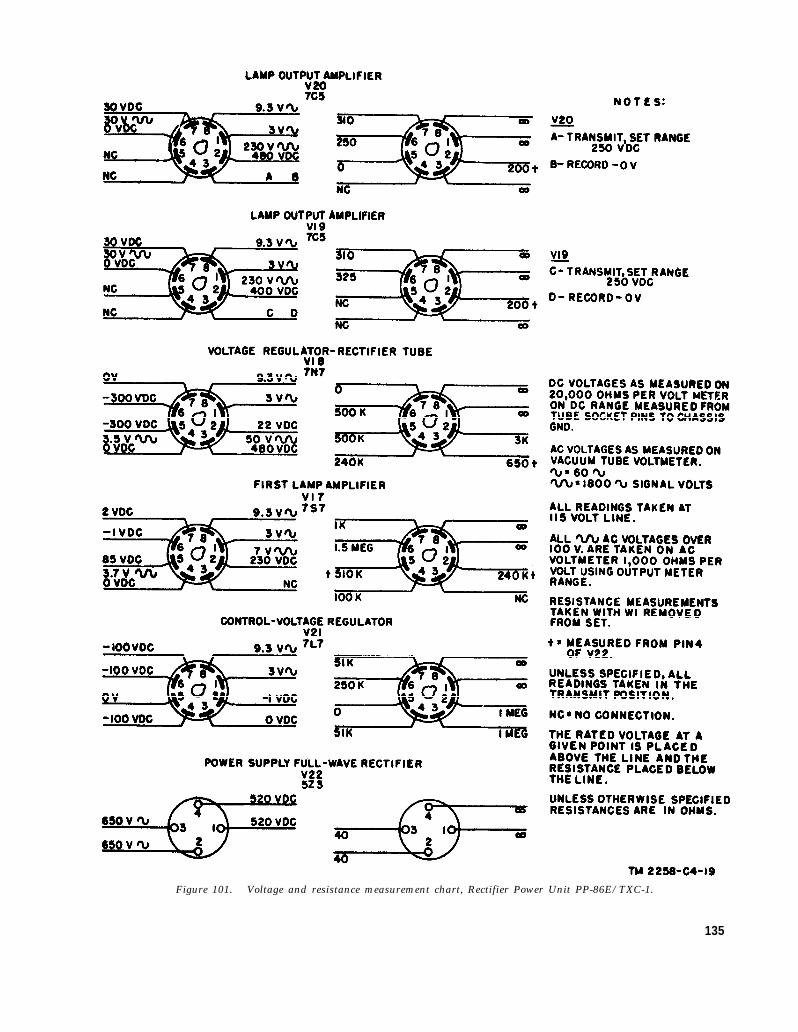
Figure 101. Voltage and resistance measurement chart, Rectifier Power Unit PP-86E/TXC-1.
135

89. Troubleshooting ChartThe following chart is supplied as an aid in
locating trouble in the transceiver and powersupply. This chart lists the symptoms which therepairman observes, either visually or audibly,while making a few simple tests. This chart alsoindicates how to localize trouble to the motorcircuit, voltage regulator circuit, signal circuits,and optical or mechanical abnormalities. Thesignal-tracing charts then can be used to supple-
ment this procedure and to determine the defectivestage. Once the trouble hae been localized to astage or circuit, a tube check and voltage andresistance measurement of this stage or circuitshould be enough to isolate the defective part.Normal voltage and resistance measurements aregiven in figures 82 through 101. Repair andadjustment of the optical and mechanical com-ponents of the transceiver are discussed inparagraphs 103 through 123.
Symptom
1. Drum does not accelerate pact syn.rihronous speed on 8TART.
2. 8ynchronou8 motor does not holesynchronism when phaaing.
3. Phase magnet armature does not re.leaee the stop arm of the clutchwhen a phaeing pulse is receivedon PHA8E.
4. With the START-PHASE switchreleased, phase magnet armaturedoee not lock to allow the stoparm to paes it freely.
5. Armature dose not releaee to engagestop arm on PHASE.
6. Pattern or jagged linee in receivedpictures (fig. 102).
7. Line feed pattern (fig. 104) .,------8. Irregular skew in received copy
(fig. 103).
Probable tmobb
Lack of proper input voltage to starlmotor,
Defective start motor -----------
Lack of motir power --------------
Defective phaae magnet -----------
Not enough electrical power applied to phaee magnet.
Improper clutch adjustment. ----Lack of voltage aoroee cathode reeia-
tore of tubes V4 and V13.Open coil in phaee magnet.
Defective phaee magnet---------.-
Improper aotion of motor thrustbearing.
Defect in lead screw or drumIrregular longitudinal travel of drum.Clutch of transmitter or receiver may
be slipping.
Cormtlon
Check switch and input voltage cirouit.
Check motor for mechanical binding.Check for open winding.
Check clutch adjustment. Check lubri-cation of worm gear and motorbearinge. Motor current may betoo low (par. 91).
Check motor and drum for msehanicafbinding. Cheek aotion of synchro-nous rotor (par. 104c).
Check adjustment of armature baoketopeorew and armature spring. Checkelectrical contacts.
Check pheeing circuit. See paragraph96.
See paragraph 106.Check tube circuits of V4 and %’13.
Check winding.
Check for a weak armature return spring,improper adjustment of PHASEportion of switch contaota, or a bindin the armature pivotc.
Check motor thrust bearing for signs ofwear (par. 104).
See paragraph 90.See paragraph 90.Examine photographic recording with a
magnifying glare. If the individualrecorded element@ areaE are inapproximate alignment, the defeot isin the transmitter system. If theindividual recorded elemental areasfollow the contour of the skew, thetrouble is in the reoorder system.When receiving on direct wordingpaper, observe direotion of skew beforeremoving paper from drum. If right’hand side of copy is skewed to the rearof the maohine, the olutch is slippingin transmitter. Cheek olutoh tension(par. 106). If temion fa oorreet, thedrum or lead screw may be binding.See paragraphs 00 and 107.
1 3 6

Symptom
9. Drum wobble which throws opticalsystem out of focus during aportion of the revolution.
10. Drum fails to feed or remains inone spot for more than 1 revo-lution.
11. Excewively high motor current, asread on MOTOR CURRENTmeter M2, or blown fuse F1.
12. Low motor current. See 11 (above)for method of indication.
13. Received copy shows straight uni-form skew or drift.
14. No output from signal amplifier- . .
15. Low signal amplifier output inTRANSMIT position.
16. Not enough contrast in TRANS-MIT position.
Probable trouble
Bent lead screw or worn bearing indrum.
Damaged half nuts- . . . . . . . . . . . . .
Motor may be short-circuited ------
Defective component in motor am-plifier circuit.
If exciter lamp does not light toits normal brilliancy, a low forkamplifier output is indicated.
Frequency of either transmitter orreceiver fork is off standard.
No input from photocell circuit inTRANSMIT position. No in-put from line in RECORD po-sition. Tubes defective. Trans-mitter optical system groundedto case, short-circuiting R51.
Gain control defective.No plate voltage.
Output load excessive.. . . . . . . . . . . . .
Exciter lamp improperly alined.Dirty lens in optical system.Low voltage across exciter lamp,
Defective photocell, Resistor R42improperly adjusted.
CorrsctlOn
Place a white sheet of paper on drum,adjust for a negative transmissionhaving a 15-db contrast range, andscan the white sheet. Note variationin output level as measured by theDB METER. The level should notvary more than )$ db in a completerevolution. Corrective measures aregiven in paragraph 99. Partial com-pensation for drum wobble can bemade by centering the exciter lamp(par. 109).
Check for binding between drum andlead screw. Examine lead screw witha magnifying glass before replacinghalf nuts.
Check motor for a short circuit. Seeparagraph 91.
See paragraph 91. If trouble persists,refer to tbe signal tracing charts.
Do not change \ubes in the fork am-plifier unit unless absolutely neces.sary. If a tube is removed and foundto be good, replace it in its originalposition. New tubes in the unsealedfork oscillator unit require about 30hours of aging to stabilize; new tubesin tbe sealed unit require about 3hours. Readjustment of R25 (un-sealed unit) or R304 (sealed unit)may be necessary when tubes arereplaced.Measure voltage between terminal 5of the fork terminal board and ground.This should be between 30 and 40volts. If it is not, test for continuityof fork coils. If voltage is correct,trace signal, using figure 74 or 75.If mechanical trouble exists in thefork or its mount, replace the entirefork oscillator unit with a new sealedunit.
See paragraph 92.
See paragraph 93.
See paragraph 9S.
See paragraph 97.
137

Symptom
— .—.
17. Low signed amplifier output inRECORD position.
18. Exciter lamp does not light, orlight is insufficient or flickering.
19. Elemental area rectangles (fig. 123)overlapping one another.
20, Background and fuzziness on directrecordings; poor contrast.
21. Final photographic copy too light..22. Mottled or intermittent reception
on direct recording.
90. Lead Screw and Drum
Prohshle trouble
Low input. Tubes deft, ctive.. _. . . .
Defective lamp. Socket corroded.Not enough input Voltage.Transformer T 15 defcctii’e.
No input signal to V 17.Objective lens of recording optical
system is misalined.Bias toolowon V13 . . . . . . . . . . .
Recorder lamp defective . . . .Stylus needle prrssure too low . . . . .
a. Line Feed Pattern. Line feed pattern (fig.104) may develop as a result of irregular longi-tudinal travel of the drum. If the drum does notadvance uniformly at the rate of 1/96 inch perrevolution, some of the photographically recordedscanning lines will overlay and others will under-lap, thereby creating a blank space between thetwo lines. If the effect is great enough to causenoticeable deterioration in the received copy, cor-rective measures must be taken. The mostcommon cause of trouble is the drum and lead-screw system. First check the arm of the drum-feed engaging mechanism to be sure it is riding onthe guide rail. Install new half nuts as a correc-tive measure. Be sure that the snubber (N, fig.122) is set firmly against the lens barrel. If thisdoes not correct the trouble, make a test recordingby substituting the drum of another machine.Be sure that the test recording is of the same typeand is made by the same method as the one onwhich the line feed pattern proved troublesome.A final test should be made by using both thedrum and the lead screw of another machine.If the line feed trouble remains, the trouble isprobably in the motor or the optical system.
b. Jag or Jitters. These are the terms used todescribe irregular or saw-tooth recording of linesthat should be straight (fig. 102). The trouble isgenerally in the motor or the clutch. It can,however, originate in the drum or the lead screw.To determine whether it is in the drum or thelead screw, first replace the motor with one fromanother machine which is operating satisfactorily,and make a test run. Use a transmission testcopy having straight lines running parallel to theaxis of the drum. The recording of the straight
138
Correction
See paragraph 93,
See paragraph 109.
Align in accordance with instructions in
paragraph 110.Increase size of cathode resistance R!~7
in 500-ohm steps.Replace recorder lamp.Adjust or replace as required.
line should not deviate from its correct positionby more than the width of one recording dot orelemental area. This is approximately one one-hundredth inch. A bind in the drum and thelead-screw system causes jitters which will beaggravated considerably if the synthetic rubberplate is too soft.
Figure 102. Enlarged examples of jitters.
c. Irregular Skew. If the receivced copy showsan irregular skew (fig. 103), it is probable thatthe clutch of the transmitter or receiver motor isslipping. This slippage often can be traced to abind in the drum system. To determine whetherthe defect is in the transmitter or receiver,examine the recorded copy with a magnifyingglass. If the individually recorded elementalareas are in approximate straight alinement, thedefect is in the transmitter system. If they followthe contour of the skew, the trouble is in therecorded system. When receiving on direct re-cording paper, observe the direction of the skewbefore removing the paper from the drum. Ifthe right-hand side of the copy is skewed towardthe rear of the machine, the clutch is slipping in the

Figure 103. Example of irregular skew.
139

Figure 104. Enlarged example of line feed overlay andunderlap.
transmitter. Check the clutch tension as outlinedin paragraph 106. If the tension is correct, takethe necessary measures to eliminate the bind inthe defective drum or lead screw (pars. 107and 108).
91. Motor Amplifier (figs. 40-46)
a. General. The output circuit of the motoramplifier includes choke T6, capacitors C28, C29,and C30, as well as the synchronous motor wind-ing.
Caution: The high voltage at the terminals ofthe synchronous motor, choke T6, and capacitorsC28, C29, and C30 may be dangerous to life.Shut off the power when connecting a meter or anoscilloscope to these components. Do not touchthe meter or the oscilloscope when the power is on.In Facsimile Transceiver TT-1A/TXC-1, do notreplace the motor fuse without discharging capaci-tor C31, or the fuse may blow. In FacsimileTransceivers TT-1B/TXC-1 through TT-1F/TXC-1, wait (a few seconds) for capacitor C31to discharge through resistor R95 before attempt-ing to replace the motor fuse.
b. Low Output. In Facsimile TransceiversTT-1B/TXC-1 through TT-1E/TXC-1, motorcurrent is read directly on MOTOR CURRENTmeter M2. In Facsimile Transceivers TT-1D/TXC-1, TT-1E/TXC-1, and TT-1F/TXC-1, M2should indicate 40 to 60 ma for 30-rpm operation,and 55 to 80 ma for 60-rpm operation.
(1) If the input to the motor amplifier is low,the exciter lamp will not light to fullbrilliancy.
140
(2) If the motor current is between 40 and70 ma for 60-rpm operation, any one orall of tubes V4, V5, and V6 may be,weak.
(3) If the current is less than 40 ma, thetrouble is probably a defective com-ponent.
(4) If motor current is excessively high, themotor may be short-circuited.
(5) If the troubles are not located by theabove checks, follow the signal-tracingcharts.
92. Fork Oscillator Unit
a. Off Frequency. If the received copy shows astraight uniform skew or a drift, the frequencyof either the transmitter or the receiver fork isoff standard.
(1)
(2)
The set under question can be tested byusing it to record radio signals from sta-tion WWV, Washington, D. C. Thesignals include 1 pulse each second.If the fork is adjusted properly, astraight-line pattern parallel to the drumclamp will he recorded.If a signal is available from a facsimiletransceiver having a fork known to bein perfect adjustment, a comparison canbe made with the set under test, andadjustments can be made. Feed theaccurate signal into the transceiver undertest through the 6-volt connection ofthe UC feed coil. Set the selectorswitch at RECORD PHOTO. Adjustthe GAIN control for a meter readingof –2 db. Move the feed coil close tothe synchronous motor. The indentionon the DB METER will rise and fall.The amount to rise and fall will dependon the position of the feed coil with re-spect to the motor. The rate of rise andfall will indicate the off-frequency con-dition of the fork. Adjust control R25in unsealed units, or R304 in sealed unitsuntil the rate of rise and fall drops to lessthan one full swing in 2 minutes.
b. Caues of Frequency Drift.(1)
(2)
Condensation of moisture on the unsealedtuning fork will cause a frequency driftuntil the moisture evaporates.Rusting of the unsealed tuning fork willaffect the frequency.

93.
a.
(3)
(4)
(5)
Slight changes in component values willaffect the frequency.
Deviations from the values shown in thesignal-tracing chart may point to thecause of off-frequency operation.
Low or high RB+ voltage may affect thefrequency.
Signal Amplifier (RECORD PHOTO)(figs. 50 through 54)Signal Tracing. Apply an input signal of
.0015 volt at 1,800 cps to LINE JACK connectorJ5. Connect a voltmeter between the grid andground of V14 with the selector switch at RE-CORD PHOTO and the GAIN control set at 100.Set Signal Generator SG-15/PCM to produce anoutput of 1 volt. Place a 100,000-ohm resistorin series with a 200-ohm resistor across this output.The output across the 200-ohm resistor will beapproximately .002 volt. This is enough to insurean input voltage that will give a test of theamplifier gain. The voltage on the grid ofV14 should be approximately 16 volts. Insome sets, it may be necessary to raise the inputvoltage to obtain the proper reading on the gridof V14. An oscilloscope (placed in the gridcircuit of V14) should show the proper waveforms(figs. 76, 77, and 78). If the voltage and wave-forms are not correct, trace the signal in accord-ance with the signal-tracing chart to localize thetrouble. The performance of stage V14 can bechecked by measuring the current in the recorderlamp circuit. The current should be approxi-mately 35 ma with proper input voltage on thegrid of V14. This current will vary somewhatwith different recording lamps and different tubes.
b. Level Changes. Occasionally, recordings willshow undesirable changes in density. To localizethe trouble, apply a steady tone, free from levelchanges, to the input of the facsimile transceiver,If necessary, connect the test meter across the in-put and watch it for several minutes; be sure thatthere is no change in level more than .2 db;watch the DB METER in the facsimile trans-ceiver for 6 to 10 minutes. Bounce or jar the setin an effort to aggravate the troubles caused bypoor contacts. If the indication on the meterremains steady, it is possible that the level changesare the result of a defective recorder lamp. Re-place the lamp with a new one. Line it up andadjust it in accordance with the instructions inparagraph 110. Take a photographic test on a
steady input signal. As a final check, a testshould be taken at several levels; for example, -4db, -1 db, +4 db, and +2 db. Plus 4 db is notan operating level, but it is possible that defectswill show up quicker when this overload signal isused.
94. DB METER Circuit
a. General. The DB METER circuit is of thevacuum-tube voltmeter type which measures theoutput of the second signal amplifier, V11 (7L7).The circuit of the meter includes resistor R70 orR71, depending on whether the selector switch isin the sending or receiving position.
b. Correct Meter Reading. Resistors R70 andR71 have tolerance values within ±10 percent.If the meter does not indicate correctly, selectresistore within this tolerance range to obtain areasonably exact reading. To determine whetherthe reading is correct with the selector switch inthe TRANSMIT position, measure the outputsignal across the LINE binding posts after con-necting a 600-ohm resistor to these terminals. Areading of 0 dbm across the LINE binding postsshould cause the DB METER in the transceiverto indicate ±2 db. If the reading is correct inthe TRANSMIT position, it will also be correctin the RECEIVE position unless the value of R71has changed. This may be checked by making asimple resistance measurement.
95. Signal Amplifier (RECORD DIRECT)
a. General. When the selector switch is set toRECORD DIRECT, the signal amplifier circuitis changed in the following manner:
(1)
(2)
Tube V12 (7C5) is cut off by opening theplate supply circuit. One section (5, 6,and 7) of V13 (7N7) is switched in andtakes the place of V12. This is done forthe purpose of increasing the contrast onthe RECORD DIRECT position. Thecut-off bias of V13 is supplied in part bybias from the cathode circuit of motoramplifier driver tube V4 (7C5).The output of V14 (1635) is switched totransformer T3. The output of T3delivers the power to the recording stylus.The switching connections include twosets of contacts to reduce the danger of ahigh-voltage flashover. When operatingthrough transformer T3, the plate voltageof tube V14 is +450 volts.
141

b. Low Output. Recordings which are not upto full density may be traced to:
(1) Excessive bias on the cathode, pin 7, ofV13.
(2) Defective transformer T2.(3) Low cathode emission in V14.(4) Flat-faced stylus or accumulation of
carbon on the stylus. Clean the stylusand rotate it 90°.
c. Blurred Recording. When the tungsten wirepoint which is set in the brass body of the stylusbecomes so worn that a reproduction is blurredduring the RECORD DIRECT process, changethe stylus needle. Loosen the spring latch (orscrew) that holds the needle; remove the oldneedle, and replace it with a new one. Locate theneedle so that the point is in contact with the sur-face of the direct recording paper mounted on thedrum when the selector switch is in the RECORDDIRECT position.
d. Poor Contrast. If the recorded copy lackscontrast, and if the transmitted signal has a rangeof 15 db, the trouble may be traced to low biasvoltage on cathode pin 7 of stage V13. Thisvoltage may be increased by raising the value ofR67 in Facsimile Transceivers TT-1/TXC-1 andTT-1A/TXC-1, or by readjusting control R97 inFacsimile Transceivers TT-1B/TXC-1 throughTT-1F/TXC-1. A defective V4 tube also maybe the cause of low bias voltage. When tubes arechanged, the bias on the cathode of V13 should bechecked.
96. Phasing Amplifier
a. No Output. To determine whether V16(884) delivers power to the phase magnet, watchthe tube when receiving phasing pulses. Thereshould be a flash within the tube at each pulsewhile phasing, providing a good phasing signal isbeing received. On Facsimile Transceivers TT-1/TXC-1 and TT-1A/TXC-1, a quick test with noreceived signal can be made by depressing thePHASE button and giving the START buttona short, quick push. A flash within the thyratronshould occur each time the START button isdepressed.
b. Signal Tracing. Connect the transceiverunder test to a second transceiver for the purposeof obtaining a phasing signal. Set the CON-TRAST control of the sending transceiver to pro-duce a 6- to 8-db phasing pulse with the CON-TRAST control in the range for negative trans-missions.
142
(1)
(2)
Connect the oscilloscope between groundand the cathode of V15 (pin 7). Withthe PHASE switch operated, the signalshould appear as indicated on the signal-tracing chart. If it does not, tracetrouble in stage V14.Check the signal at the other pointsindicated in the signal-tracing chart.
c. Phase Magnet. The phase magnet is part ofthe cathode circuit of stage V4 when the PHASEbutton is not depressed. Failure of the phasemagnet to lock when the PHASE button is notdepressed may be traced to stage V4. ResistorR40 is in the cathode circuit of V4 only when thebutton is depressed.
97. Photocell Circuit
a. Signal Tracing. Because of the sensitivenessof the output of the photocell circuit, it is notpractical to make direct measurements with ameter or an oscilloscope. It is convenient to usethe signal amplifier to feed the oscilloscope, whichcan be connected across the LINE terminals.The signal amplifier and meter circuit first mustbe checked for satisfactory operation. If therequired measurements on the DB METER andoscilloscope are not obtained, the circuit should betraced on a stage-to-stage basis as indicated in thesignal-tracing chart. If the photocell has beensubjected to high humidity, it may require replace-ment. Its dc resistance, measured on an ohm-meter when no light is shining on the cell, shouldexceed 10 megohms. Be sure to readjust R42after replacing the photocell with a new one.
b. Output Requirement. Set the GAIN controlat 100 and adjust the CONTRAST control for aminimum meter reading when the scanning beamis on the phasing spot. This is the condition forpositive transmission. The DB METER shouldindicate +2 or +3 db when the scanning beam ison the raised portion of the phasing ring. Theequipment will operate satisfactorily even thoughthe reading is not above 0 db. It is desirable,but not necessary, to have the 2- or 3-db margin.If the output level is not proper, check the align-ment of the optical system; check amplifier stagesV10, V11, and V12; then check the voltage acrossresistors R41, R42, and R43. This should bebetween .4 and .6 volt.
c. Low Contrast. Insufficient contrast when bal-anced on black or white generally can be correctedby the adjustment of resistor R42. Excessivevoltage from the fork unit reduces the contrast

range. The voltage can be reduced by shuntingthe output of the fork unit with a 2,000-ohmresistor. Sometimes, the correction can be madeby increasing the value of R49 (except in Facsim-ile Transceivers TT-1D/TXC-1, TT-1E/TXC-1,and TT-1F/TXC-1). The exact amount of thisincrease can be determined by experiment. Lowcontrast also may be caused by lack of light fromthe exciter lamp (par. 102).
98. Signal Amplifier (TRANSMIT)a. Low Output. The signal amplifier circuit,
with the selector switch in the TRANSMIT posi-tion, is a modification of the signal amplifier circuitwith the selector switch in the RECORD PHOTOposition. In practice, it is generally found thatif the signal amplifier operates correctly in theRECORD PHOTO position, it performs properlywith the switch in the TRANSMIT position. Aquick check to determine whether the input circuithas been properly switched to the photocell circuitis to place a screw driver under the extension ofthe photocell shield pan. Do not let the bladetouch the grid connection or the pan. If theamplifier is performing properly, it breaks intooscillation. In most cases, if the input circuit isopen, oscillations will be present and will be indi-cated by continuous flickering of the DB METER.
b. Signal Compression. Connect the oscillo-scope and DB METER across the LINE termi-nals. The waveform should be sinusoidal be-tween the balance point and +2 db. If the wave-form tends to compress before reaching +2 db,trace through the circuit to localize the trouble.The flattening or compression of the signal maybecaused by low plate voltage, low cathode biasvoltage, low screen voltage, or defective tubes.
99. Signal Amplifier (STANDBY)With the selector switch of Facsimile Trans-
ceiver TT-1/TXC-1 in the STANDBY position,the fork oscillator signal to the motor amplifier iseffectively short-circuited to ground through pin9 of the Jones plug and the exciter lamp and itscircuit. (In all other facsimile transceivers, theSTANDBY-MON-TALK switch (S5) also mustbe at STANDBY.) In Facsimile TransceiverTT-1C/TXC-1, the B+ circuit to the motor isopened when selector switch S1 and STANDBY-MON-TALK switch S5 are both at STANDBY.By short-circuiting the 1,800-cycle signal to themotor amplifier, the power to the synchronousmotor is practically cut off. There is only a small
residual dc flowing in the synchronous motorcoils. Failure of the signal amplifier circuit tooperate properly may be caused by a burned-outexciter lamp or a poor switch contact. The dis-appearance of the characteristic 1,800-cycle tonein the synchronous motor indicates proper opera-tion of the grounding circuit.
100. B+ Voltage Regulatora. Requirements. The B+ voltage regulator
must deliver voltage that does not vary more than2 volts when operating conditions change. Thevoltage may be anywhere between 240 and 255volts dc. The measurements may be made at thebottom end of resistor R88 or R89 on the regulatorpanel terminal strip, or on pins 3 and 6 of stageV16 in Facsimile Transceivers TT-1/TXC-1 andTT-1A/TXC-1. This voltage is measured byRB+ meter M3 in Facsimile Transceivers TT-1B/TXC-1 through TT-1F/TXC-1.
b. Effects of Poor Operation. If the regulatedvoltage is too high, the fork frequency deviatesfrom 1,800 cycles and causes a noticeable drift inthe recorded copy. A low voltage also will resultin a drift and permit the amplifiers to overload ona high signal level. The overloading shows up asflattened high lights when transmitting for nega-tive reception, or flattened shadows when trans-mitting for positive reception. A flickering volt-age regulator may produce level changes and mayoscillate when the line voltage is low. Theoscillations will show up in the recorded copy.
c. Tracing trouble. When trouble is suspectedin the regulator unit, check the output voltagewith the line voltage varying between 100 and 130volts. The ac input frequency may be between 50and 65 cycles. Watch the test voltmeter forseveral minutes when level change trouble is beingtraced. If the voltage takes a jump when the linevoltage is within a few volts of 110, there isdanger of the regulator breaking into oscillationat low line voltages. If it is important to operateat an exact line voltage, it will be necessary to usean accurately calibrated voltmeter to measure theline voltage. Most rectifier-type voltmeters canbe depended on for an accuracy of 5 percent attemperatures between 65° and 100° F. Aboveand below these temperatures, the accurary isgenerally poor. If it is found that the regulatedB+ voltage is not within the correct range, checkthe voltage across regulator lamp V25 (5651).This can be done by measuring the voltagebetween cathode pin 7 of tube V9 (7L7) and
143

ground. Use the 250-volt scale of a voltmeterhaving a resistance of 1,000 ohms per volt orhigher. The voltage across the regulator lampshould be between 82 and 92 volts. If the voltageis found to be correct, test V9 or try a new tube.Weak tubes in stages V7 and V8 maybe responsiblefor a low RB+ voltage. There is a possibilitythat an excessive load is responsible for the lowoutput voltage. If there is reason to suspect this,disconnect the load from the regulator panel andmeasure the open-circuit voltage. If it is neces-sary to trace further, test thethe correct value. Capacitors,must be tested for leakage.
components forespecially C57,
101. Rectifier Power Supplya. General. The term rectifier power unit is
used to describe the complete unit, which includesthe conventional rectifier power supply and theexciter lamp power supply system. In this para-graph, the term rectifier power supply does notinclude the exciter lamp supply system.
b. Tube replacement. Rectifier tube V22 (5Z3)may require replacement after a few hundredhours of operation, especially if the equipment isto operate on low line voltages; that is, 100 to 110volts. A tube selected for hugh emission permitsoperation on voltages between 90 and 100. If
Section Ill. REPAIRS
103. GeneralExcept in cases of simple trouble, do not attempt
to repair mechanical parts such as the motor, thelead screw, the drum, and the tuning fork unlessnew parts are not available. Put replacementsand lead wires in the same physical location as theoriginal. When replacing components in theamplifier system, take into account protectionnecessary because of high voltages.
104. Synchronous Motor Unit(figs. 105, 106, and 107)
Caution: Work on the synchronous motorshould be done in a clean, dry place. Disassembleand assemble motor parts with care, avoidingrisks of scratching and damaging any of themachined surfaces. Be careful not to lose thelower thrust bearing ball (R, fig. 105) when dis-assembling the motor.
a. Top Bearing (B, fig. 105). It is not practicalto replace this bearing in the field. Use solvent(SD) to remove gummed-up oil and grease. After
144
the unregulated B+ voltage falls below 400when the line voltage is 100, the tube emissionis too low for satisfactory operation. Tube V22should be replaced after each 500 transmissions.
102. Exciter Lamp Supply
a. Signal Tracing. For a quick check of satis-factory operation, measure the voltage across theexciter lamp. It should be between 6.1 and 6.3volts at any line voltage between 100 and 130.The measurement is made at the terminal stripin the power supply. The voltage drop to thelamp socket is approximately .2 volt. If thevoltage is not correct, measure the voltage on grid4 of stage V17 (7S7). This should be about 4volts ac, as measured with a vacuum-tube volt-meter. If further signal tracing is necessary,follow the steps shown in the signal-tracing chart.The exciter lamp should be replaced after each 500transmissions.
b. 0utput Transformer T15. When the exciterlamp burns out, the load on transformer T15becomes practically zero, resulting in a very highvoltage across secondary No. 1. There have beentransformer failures as a result of the high voltage.In tracing trouble, consideration must be given tothe probability of failure of this transformer.
AND ADJUSTMENTS
the bearing has been thoroughly cleaned, dry outall traces of the solvent before re-oiling.
b. Lower Bearing (fig. 105). In motors withserial numbers below 1157, do not attempt toreplace the side-wall bearing in the field. Cleanand re-oil. In motors with serial numbers above1157, side-wall bearings (C, fig. 105) are of theball-bearing type. These bearings may be re-placed when defective. If tests indicate thatsynthetic rubber pad P is too soft, replace it.If the pad is too hard, a portion of the center canbe cut away. If bearing ball R is replaced,select one that will not bind on the side wall ofthe bearing.
c. Synchronous Rotor Bearing (D, fig. 105).This bearing cannot be replaced in the field.If the rotor turns too freely on the shaft and doesnot fall into synchronism as it should, the freeoscillating action must be reduced by adding someend thrust. Insert a thin washer (U) betweenthe felt washer (V) and collar (S) Remove thecollar after driving out the taper pin (T) with a

Figure 105.
pin punch having a tip approximately .05 inchin diameter.
d. Commutator (E, fig. 195). Clean the com-mutator with a rubber eraser, preferably onecontaining grit, such as an ink eraser. Do notuse emery or sandpaper.
e. Synchronous Motor Field Coils (F, fig. 105).In emergencies, a defective coil can be discon-nected and the motor operated on three of its fourcoils. The power will be reduced, making itdifficult to phase. Motors with serial numbersabove 1000 have six poles; those below this serialnumber have four poles. The removal of onecoil does not materially reduce the motor power.When ordering replacement parts, be sure to selectthe proper replacement coil. For replacement ofsynchronous motor coils and bushings on syn-chronous motors KBA-1 and KBA-2, use theappropriate Signal Corps Motor Coil ReplacementKit.
f. Lead-In Bushings. Defective lead-in bush-ings are the most common causes of motor coilsburning out. Keep them clean at all times and,when possible, replace then with nylon bushings.Nylon bushings are supplied on KBA-1 motors.Ceramic bushings are supplied on motor KBA-2.Refer to e above for information on replacementbushings.
g. Brushes (C, fig. 109). To replace the brushesin motors supplied with Facsimile TransceiversTT-1/TXC-1 and TT-1A/TXC-1, remove thearmature extension (A) of the start magnet anddisconnect the brush leads from the terminal(H). If the bakelite sleeve (B) is in good con-dition, replace only the carbon brush (C) and its
Synchronous motor, early models.
flexible lead. The brush can be pulled loosefrom the bakelite sleeve. In some cases, it may
be necessary to warm the brush with a solderingiron or soak the brush and tip of the bakelitesleeve in glyptal solvent.
h. Synchronous Motor, Parts Description (fig. 105).
Refsymbol
AB
c
c
D
EF
G
H
I
JK
L
M
No
P
Name of psrt snd description
MOTOR, ac: 1,800-cycle,synchronous.
WICK, felt ------------BEARING, composition:
$&”.BEARING, composition:
%6”.
BEARING, ball: }f” odby ~e” id by ~z” w.
BEARING, composition:%,”.
COMMUTATOR ------COIL, field: 125 ohms---
BRUSH ASSEMBLY,electrical contact.
GEAR: 30 teeth, 40pitch.
SHAFT, synchronousmotor: start motor,worm.
ARMATURE, series type.COIL, series field: 2
ohms.SPRING, synchronous
rotor coupling.SHAFT, drive ----------
BEARING, ball -..... -.PLATE, bottom---- . . . .
RUBBER, synthetic . . . . .
Functlnn
Driver for drum.
Oil reservoir.Top bearing.
Lower bearing on mo-tors below serialNo. 1157.
Lower bearing on mo-tors above serialNo. 1157.
Synchronous rotorbearing.
Reverses current.Synchronous motor
field coils.Supports motor
brushes.Reduction gear.
Motor shaft andworm.
Start armature.Start motor field coil.
Couple rotor to shaft.
Drives clutch assem-bly.
Drive shaft bearings.Thrust bearing re-
tainer.En f-thrust de-
coupling.
145

*f I Name d part and drsmil,l kmsymbol I..—. .—, - ..——— .— —-- -— . . . .- .
QR
R39
s
T
u
v
wx
.
PLATE, thrust ----- . . . . .BEARING, hnll : steel ;
)4” dia.RESISTOR, fixccl : ww ;
7,500 ohms, * I 070; 20w.
COLLAR, thrust: IIISO Ispring anchor.
PIN, taper: 7/0. -
WASHER, bnkelite:thrust.
WASIIER, felt: thrust. . .
ROTOR, Synchronou s...BEARING, hall; steel;
~’ dia.
Vuwl i,,ll_.. .-
Thrust, Ixdl retniner.Thrust Iw:wing.
Volt:igc clroppi[lg rc-.sistor,
Thrust collur :mdspring :tuchor.
Sccurv spring ullclwrto Sluift .
Thrust Ixwrillg fors.vnchromus mtur.
Thrust Ixwrings forsyttchrol]olls rotor.
Synchro]wus rotor.Thrust, bcuriuK for
shnf t twswnhly.
i. Gear (H) (fig. 105). The gear on the driveshaft can be replaced if suitable shop facilities areavailable. Pin the new gear to the shaft with ataper pin. Sometimes, a damaged gear can bemoved along the shaft and pinned in a new placeso that 23 good portion of the gear will mesh withthe worm.
j. Phase Magnet (fig. 108). The armaturereturn spring (H) must produce a strong springaction. Replace the spring if the tension is tooweak. Pivots (F) and (G) must not cause bindsor side play. To adjust the armature backstop(B), set up the transceiver for a receiving teston a phasing signal. Proceed as follows: Withthe PHASE button depressed, back off the ad-justing screw until the armature fails to operate.Screw in the armature back screw until the arma-ture fails to catch the top arm. Return the screw
Figure 106. Synchronous motor, KBA-2.
146

Figure 107. Synchronous motor KBA-2, showing use of spanner wrench.
to a position halfway betweem the two points.The head of the screw is hexagonal so that fractionsof turns can be counted. The armature shouldoperate satisfactorily over a range of approxi-mately 1 turn. If the range is less than 1 turn,the armature return spring may be too tight orthe armature may be binding at the pivots. Ifthe range is greater than 1 turn, the spring may betoo loose.
k. Start Magnet (fig. 109). Poor operation ofthe start magnet in motors with serial numbersbelow 1193 may be caused by the magnet arma-ture rubbing against the motor casting. Thiscan be cleared by loosening the magnet mountingscrews and shifting the frame slightly. Check
the action of the armature and brushes for free-dom from finds. A lug which straddles thearmature spring serves as a backstop to limit theupward movement of the armature. Adjust thisbackstop by bending the lug so that brushes liftapproximately one-sixteenth of an inch off thearmature. Test by pushing the armature down-ward with a pencil and noting the free armaturetravel before the brush springs begin to compress.Motors with serial numbers above 1193 areprovided with a different type backstop whicheliminates this trouble. Motors in FacsimileTransceivers TT-1B/TXC-1 through TT-1F/TXC-1 have no start magnet.
147

l. Phase Magnet, Parts Description (fig. 108).
J!&
A
B
c
D
E
F
(3
H
Num of P8R and detorlptton
PHASE MAGNET ASSEMBLY.
ARMATURE . . . . . . . . . .
SCREW, backstop... - . .
COIL, solenoid: 3,000ohms.
SCREW, sore looating:No, 6-32.
SCREW, nets: No. 3-32
PIVOT ----------------
PIVOT ----------------
SPRING -------------
.—-. —— --
Function
Phase drum,
Atmature ● nd stoplstoh.
Armature baokutopadjwtment.
Eleotromsgnet.
Core position adjust-ment.
Sat sorews for lookingoore in plain,
Fixed armature ful-crum pivot,
Adjustable armaturefulorum pivot.
Armature returnspring.
.—. ——Note. The core locating sorew (D) is not used in the
phaee magnet assembly of Faosimile Transceiver TT-lC/TXC-1.
m. Start Magnet, Parts Description (fig. 109).
netsymbol
A
B
c
D
E
:
H
1
148
Name of ~ and deacrlptkm.. —-—___
START MAGNET AS-SEMBLY.
ARMATURE EXTEN-SION.
BRUSH A8SEMbLYelectrical oontact: mo-tor; includes bruoheu,sleeves, springs, brusharme, and nub,
BRUSH, eleetrioel con-taot.
SPRING, brush . . . . . . . . .
SPRING, ● nature. . . . . .
BACKSTOP, ● rmature. .SCREW, armature ex-
tansiono
SCREW, binding head...
NUT: No. 246. --------
Funotton
Movm brushes in wm-tact with commu-tator.
Brwh actuator,
Brush and brush hold-efn,
Commutator brush,
Brush preanure eon.trol.
Armature returnnprlng.
Arrrmture baokstu)p.Remove brush am-
bly for replace-ment.
Brush pigtdl oon-neotor.
Hold brush aasemblyin plaoe.
Figure 108. Phase magnet.

Figure 109. Start magnet.
105. Replacing Worm and Gear inSynchronous Motor KBA-2
(figs. 110 through 113)Normally, the gear should be replaced when the
worm is replaced. Although the gear may notdisplay excessive wear, it becomes, in time, chargedwith abrasive particles which may cause unduewear on a new worm. Refer to figures 110 through113 before starting replacement. The motor maybe left mounted on the facsimile set during re-placement.
a. Remove the spanner wrench and the topcover plate (four screws) from the gearbox. Re-move the No. 6 Allen setscrew wrench (mountedon clip on gearbox).
b. Insert the No. 6 Allen setscrew wrench inthe taper screw of the worm, and grip the slot withthe spanner wrench (figs. 110 and 113).
c. Loosen the taper screw, remove the Allenwrench and the spanner wrench, and pull theworm gear up out of the motor shaft.
d. Remove the bearing cover plate (four screws).e. Loosen the gear-collar set screw (fig. 113).
f. Remove the bearing, gear collar, and gearfrom the countershaft with finger pressure appliedas shown in figure 112.
g. Remove the gear collar from the gear andplace this collar on the new gear.
h. Slide the assembly (gear collar and new gear)onto the countershaft.
i. Inspect the bearing. Note that on one sideof the bearing the inner race is flush with the out-side race. The inner race is recessed on the otherside of the bearing. Insert the bearing onto thecountershaft with the recessed inner race sidetoward the outside of the gearbox (the side uponwhich the bearing cover plate is mounted). Sincethe inner race rotates with the countershaft, as-sembly in this manner will insure against the innerrace rubbing on the bearing plate when the plateis replaced.
j. Replace the bearing cover plate.k. Center the gear (and the gear collar) on the
countershaft so that the gear is at the hole in themotor shaft that receives the worm.
l. Place the new worm into the motor shaft holeand tighten it with the Allen setscrew wrench andthe spanner wrench. The worm now should bein mesh with the gear.
m. Move the gear (and the gear collar) alongthe countershaft in either direction until it isstopped by the worm. Now move the gear in theother direction along the countershaft until it isstopped by the worm. The distance of lateralmovement of the gear along the shaft allowed bythe worm will be approximately one-sixteenth ofan inch. Moving the gear one-half of this dis-tance from either extreme will center the gear onthe worm.
n. Tighten the gear-collar set screw.o. The new worm must be mounted with partic-
ular orientation to the motor shaft where wormand gear run smoothest. Turn the power on andstart the motor.
Note. There is danger of high-voltage shock when work-ing near the motor with the power on. Use extreme cau-tion when making adjustments described in the rest ofthis paragraph.
p. With the motor running at synchronousspeed, place two fingers of the left hand on thetop of the motor gearbox, one finger above eachcountershaft bearing. The trembling sensationthat will be felt must be minimized to insuresmooth worm and gear operation. (To ascertain
149

Figure 110. Top plate removed from motor.
how much this trembling can be minimized, letthe motor run with no worm in the motor shaftwhile feeling with the fingers on top of the motorgearbox.)
q. Stop the motor. Place the transceiver in theSET RANGE position. In this position, the fieldcoils of the motor will offer enough resistance torotation of the motor shaft to permit the worm,when the taper screw is sufficiently loosened, tobe rotated without, rotating the motor shaft.Loosen the taper screw, using the Allen and span-ner wrenches.
r. Slightly rotate tile worm in the motor shaftand retighten the taper screw.
s. Start the motor and, once again, feel thegearbox above the countershaft bearings to seewhether the trembling has increased or decreased.
t. Repeat the procedures in r and s above; al-ways rotate the worm slightly in the same direc-tion until little or no trembling is felt.
150
u. Check the tightness of both the worm taperscrew and the gear-collar setscrew. Lubricate witha thin film of Grease, Aircraft and Instruments(GL) on the worm and gear.
v. Replace the spanner wrench and the gearboxcover and replace the Allen setscrew wrench in itsclip.
106. Clutch(figs. 114, 115, and 116)
a. Primary Clutch. The primary clutch tensionshould be 12 to 14 ounces. Make a dynamicmeasurement with the motor running and thedrum held stationary by means of a string wrappedaround the drum and attached to the scale (fig.114). To adjust primary clutch tension, stop themotor and loosen the clamp screw (G, figs. 115and 116). The spring retainer (F) can be pushedforward or backward in Facsimile TransceiverTT-1/TXC-l, serial numbers 1 through 90; in

Figure 111. No. 6 setscrew wrench inserted into worm.
all later models, tension is adjusted by turning theretainer on its screw thread.
Warning: Never run the motor with the clampscrew (G) loose, or the gears may be stripped.
b. Secondary Clutch. The secondary clutchtension should be approximately one-half thatof the primary clutch (6 to 7 ounces). In FacsimileTransceivers TT-1D/TXC-1, TT-1E/TXC-1,and TT–1F/TXC-1, the secondary clutch tensionshould be between 3 and 6 ounces. If the second-ary clutch is too loose, the stop arm and dog tripwill come together too rapidly and possibly throwthe motor out of synchronism or slip the primaryClutch. Slipping of the primary clutch duringthe phasing operation will result in out-of-phaserecording. If the secondary clutch tension is tooheavy, the secondary clutch load added to the
primary clutch load may cause the motor to stallduring the phasing operation. Make a staticmeasurement of the secondary clutch tension.With the motor stopped, and the string wrappedaround the drum, pull the string to rotate thedrum while reading the scale. Be sure that themeasurement is taken when the dog latch isengaged with the secondary clutch ring to obtaina correct measurement. The secondary clutchtension is adjusted by means of screws (P, figs. 115and 116). If screws work loose, lock the heads inplace with glyptal after making correct adjust-ments. Before using glyptal, remove all greasewith solvent (SD). If the screws are of the slottedtype, spread the sides slightly by inserting a smallscrew driver or knife into the slot.
151

152
TM 2258-C1-17
Figure 113.
TM 2258-C1-16
Figure 112.

c. Clutch Assembly, Facsimile Sets AN/TXC-1,-1A, and -1B, Parts Description (fig. 115).
Refsymbol
AB
C
D
E
F
G
H
I
J
K
L
M
N
0
P
Name of put and description
CLUTCH ASSEMBLY:Part of countershaftdrive assembly.
ARM, stop.CLUTCH, ring.
RING: composition,clutch plates.
PLUG: composition,clutch,
SPRING --------------
RETAINER, spring----
SCREW, clamp: No. 6-32
RETAINER: clutch as-sembly.
BEARING, clutch ------
PIN, taper: 7/0---------
SCREW: No. 4-40 ftat-head.
PLATE, pressure-- - - - -
SHAFT, drive ---------
CLUTCH: secondary,bearing.
SPRING, secondaryclutch.
SCREWS: No. 4-40 . _.
Function
Holds back drum whilephasing.
Stop arm and driver.Retainer for friction
driver plugs.Driving part of clutch.
Driven part of clutch,
Clutch pressuresprings.
Clutch pressurespring,
Clamps spring retain-er to shaft.
Clutch assembly re-tainer and clutchplate driver.
Hub for clutch as-sembly.
Secures clutch bear-ing to drive shaft.
Holds clutch retain-er to clutch bearing.
Transfers spring pres-sure to clutch.
Drives clutch assem-bly.
Secondary clutchbearing.
Secondary clutch*pressure.
Adjust pressure onsecondary clutch.
Secondary clutchring.
Note. In the clutch assembly ueed on Facsimile Trans-ceiver TT-1C/TXC-1, serial numbers 1-165, Espey partNo. A21.771 replaces parts with reference symbols C and
Figure 114. Method of measuring primary clutch tension, H, shown above.
153

Figure 115. Clutch assembly, Facsimile Sets AN/TXC-1, -1A, and -1B.
d. Clutch Assembly, Facsimile Sets AN/TXC-1C,and AN/TXC–1D, Parts Description (fig. 116).
Ref.symbol
AB
C
D
E
F
G
H
Name of part and description
CLUTCH ASSEMBLY;p/o countershaft driveassembly.
ARM: stop -------------CLUTCH RING --------
RING: composition,clutch plates.
PLUG: composition,clutch.
SPRING ---------------
RETAINER, spring -----
SCREW, clamp: No. 6-32; fillister head.
RETAINER PLATE:clutch assembly.
Function
Holds back drumwhile phasing.
Stop arm and driver.Retainer for friction
driver plugs.Driving part of clutch.
Driven part of clutch.
Clutch pressurespring.
Clutch pressurespring.
Clamps spring re-tainer to shaft.
Clutch assembly re-tainer and clutchplate driver.
.Ref
symbol— . —
1
J
K
L
M
N
0
P
Q
R
Name of part and description
BEARING, clutch ------
PIN, taper -.----------
SCREW: No. 4-40; flat-head.
PLATE, preasure -------
SHAFT, drive ------.--
BEARING, secondaryclutch.
SPRING, secondaryclutch.
SCREW ---------------
RING, secondary clutch-
BEARING, needle- - ---
Function
Hub for clutch as-sembly.
Secures clutch bear-ing to drive shaft.
Holds clutch retainerto clutch bearing.
Transfers spring pres-sure to clutch.
Drives clutch assem-bly.
Secondary clutchbearing.
Secondary clutchpressure.
Adjusta pressure onsecondary clutch.
Secondary clutchrings.
Bearing for clutch as-sembly.
154

TM 2258-C2-9
Figure 116. Clutch assembly, Facsimile Sets AN/TXC-1C and AN/TXC-1D.
e. Lubrication. Erratic clutch tension usuallyindicates the need for lubrication. Refer to paar-graph 136.
f. Alinement of Shaft. For proper operation ofthe clutch and drive assembly, the shaft (M) mustbe in alinement with the lead screw. The up-and-down alinement can be controlled in FacsimileTransceiver TT–1/TXC–l by the mounting screwsof the motor, provided the motor has rubbergrommets in the mounting holes. Motors with-out grommets are machined in a jig and shouldgive no trouble in this respect.
g. Dog Latch Cam Plate. Excessive wear anddamage are caused to the dog latch cam plate bysetting it improperly. The cam plate should beadjusted so that it first begins to trip the doglatch after the dog latch haa traveled approxi-mately one-fourth of an inch past the end of theplate. The plate must engage the dog latch nearthe tip to insure enough leverage. Adjustmentcan be made by sliding the entire dog trip armassembly along the lead screw or by changingshims under the cam plate. The dog latch andtrip arm must operate freely under a light tensionfrom the springs.
107. Drum(figs. 117 and 118)
a. General. The drum of Facsimile Trans-ceiver TT–1(*)/TXC–1 is constructed as illus-trated in figures 117 and 118.
b. Half Nuts. If the half nuts (split nuts) be-come damaged, replacement may be made fromthe spares provided with the equipment. Inolder equipments, each half nut holder is num-bered. Later equipments will accept stock halfnub, and their retainers are lettered A and B.The half nuts must be matched with the corre-spending markings on the retainer.
c. Binding. If the drum tads to bind on thelead screw when it is turned or moved along thelead screw by hand, it is possible that the leadscrew is bent or nicked. A nick in the guide railmay cause binding. Do not blame the drum un-less other repairs fail to solve the trouble. Bindssometimes can be cleared by flushing the drumbearings with solvent (SD) and relubricating withoil (PL Special).
d. Jitters (fig. 102). If the key (B, figs. 117and 118) is too loose and is free to move sidewise,jitters may occur in the recorded copy. If replace-ment parts are not available, a temporary repairmay be made by squeezing the walls of the keyretainer.
e. Tension Adjustment. If phasing troublesoccur in Facsimile Transceivers TT-1B/TXC-1through TT-1F/TXC-1, tighten the drum-tensionadjusting screw one-half turn. This is the upperscrew on the left-hand lead-screw bearing block(fig. 1 19).
f. Removal of Paper Clamp in Facsimile Trans-ceiver TT–1C/TXC-1.
(1) To remove the paper clamp from thedrum, proceed as follows:
(a) Place a blunt instrument, preferably apiece of hard wood, against the left-hand edge of the paper clamp (C,fig. 117) and give it a sharp rap witha hammer.
(b) Slide the paper clamp to the right aboutone-half inch, then lift the clamp outof the drum.
(2) To remove the interred lever assembly,proceed as follows:
(a) Remove the knob on the right-handside of the drum.
(b) Remove the mounting plate and slidethe assembly out of the drum.
155

TM 2258-33
Figure 117. Drum assembly, Facsimile Transceivers TT-1/TXC-1, TT-1A/TXC-1, and TT-1B/TXC-1.
156

TM 2258-C1-2Figure 118. Drum assembly, Facsimile Transceivers TT-1C/TXC-1, TT-1D/TXC-1, TT-1E/TXC-1, and TT-1F/TXC-1.
157

g. Drum Assembly, Parts Description (figs. 117and 118). Ref
symbol
Refsymbol
AB
CD
E
F
G
H
J
Name of part and description
DRUM, facsimile trans-ceiver.
DRUM SLEEVE.. . . . . .KEY------------------
CLAMP, paper and film-CONTROL LEVEL,
paper and film clamp.
LEVER, cam plate -----
RING, phasing ----------
HALF NUTS -----------
RETAINER, half nut---
STOP, drum ------------
Function
Holds, rotates, andspirals copy.
Outside of drum.Drives drum through
contact with key-way in lead screw.
Secures copy to drum.Opens and closes
paper and filmclamp.
Operates cam con-trolling half nuts.
Reflects light duringphasing.
Feed drum along leadscrew.
Mounting for halfnuts and left-handend drum support.
Bumper betweendrum and bearingblock.
108. Lead Screw(fig. 119)
a. Cleaning. Clean the lead screw thoroughlywith solvent (SD). Be careful not to scratchthe threaded portion. After cleaning, inspect forscratches and nicks, using a magnifying glass.If nicks appear in the threaded portion, the threadssometimes may be chased by a skilled machinistworking with a hand tool. Any nicks or dentsin the other portion of the lead screw should beemoothed out with a fine oil stone. Examinationof the lead screw should include an inspectionof the bearing (K, fig. 119). Replace the bearingsthat cause the lead screw to bind.
b. Keyway. Nicks in the keyway will causejitters in the recorded copy. A nick sometimescan be smoothed out with a very fine three-corneredfile; the file mark may be smoothed out with afine stone.
c. Lubrication. After a lead screw has beencleaned, inspected, and repaired, lubricate it asdirected in paragraph 46.
d. Lead Screw, Dog, and Bearing Parts Descrip-tion (fig. 119).
A
B
C
D
E
F
G
H
I
J
K
Name of part and description
LEAD SCREW ASSEM-BLY: lead screw.
LEAD-SCREW PRES-SURE PLATE.
DRIVE DOG ASSEM-BLY.
CAM, dog latoh ---------
BLOCK, bearing: rh----
BLOCK, bearing: 1h. ----
SPRING ---------------
ARM, dog trip -----------
LATCH, dog ------------
PLATE, drum stop ----B-
EARING, ball -------
Function
Rotates and feedsdrum assembly.
End thrust bearing.
coupled lead screw tomotor clutch.
Causes dog latch toto disengage fromclutch.
Supports right-handend of lead screw.
Supports left-handend of lead screw.
Preloads thrust bear-ing.
Drives lead screwfrom primaryclutch.
Drives lead screwfrom secondaryclutch.
Dust shield for bear-ing and drum stop.
Lead-screw bearings.
109. Transmitter Optical Systema. General. Dirt on the lenses or poor adjust-
ment of the optical system will cause insufficientlight on the photocell.. Before tracing trouble,clean and adjust the system in accordance with eand f below. Aline the exciter lamp after each100 transmissions, Refer to figure 120 for trans-mitter optical system used in Facsimile Trans-ceiver TT-1/TXC-1 through TT-1C/TXC-1.Refer to figure 121 for transmitter optical systemused in Facsimile Transceiver TT-1D/TXC-1,TT-1E/TXG-1, and TT-1F/TXC-1.
b. Inspection. The following points in thetransmitter optical system muet be examined fordefects before starting any repair work:
(1)
(2)
Exciter lamp. The exciter lamp may havea poor internal contact which causes it toflicker. Try a second lamp known to begood to determine whether the first lampis at fault. Be sure the lamp is in itaright position and not rotated 180° in thesocket. Check the position each timethe lamp is removed.Socket. Examine the socket for good con-tact. Be sure there is no corrosion.
158

TM 2258-27
Figure 119.
(3)
(4)
(5)
(6)
This can be done by forcing the lamp upand down and sideways with the currenton. If the lamp flickers, repair or re-place the socket. Side play may causethe lamp to go out of focus. Examinethe connections to the socket, especiallythe connection to the shell of the socket.Test the spring in the socket to be surethat it operatea freely to give a strongcontact pressure to the lamp.Socket mounting plate. Examine thescrews that hold the socket mount inplace to be sure that they are set uptightly on the bakelite holder, There isa possibility that the bakelite may haveshrunk away from the screws, causingthem to become loose.Lamp holder bracket assembly. Thebracket assembly must not move when apressure of approximately 10 pounds isapplied by hand. If it does move, springtension (L) under the cam screws (G)and (F) (fig. 120) is too light. The ten-sion may be increased by taking 1 fullturn on the screw. It is possible thatthe spring leaves may be broken. If so,replace them.Condenser lens. Examine the condenserlens for dirt and improper fitting in themount.Objective lens barrel. Inspect the objec-tive lens for dirt and fitting in the mount.The barrel must not be loose in the block.Inspect the lens for defects. It may benecessary to remove the lens barrel. If
(7)
the cement between the elements of thelens appears to be fern-like when exam-ined under a magnifying glass, replacethe lens. If any other defects appearunder examination with a magnifyingglass, replace the lens unless the defectsoccur only at the outer rim of the lens.Photocell socket. Remove the pan underthe photocell and examine the socketconnections.
c. Exciter Lamp Socket. Do not replace theexciter lamp socket with any ordinary type auto-mobile socket. The socket must be constructedwith strong springs behind the contact, and in-sulated with bakelite, not hard rubber.
d. Lamp Bracket. If it is necessary to tightenthe lamp bracket, keep in mind that the eccentricaction of the top screw moves the bracket side-ways, and the eccentric action of the bottom screwraises and lowers the bracket. The center operat-ing position of the screw heads is marked with ared dot. Do not attempt to obtain alinementwith the red dot one-fourth or one-half turn offcenter. The dot should not move more than 45°either side of center. If it is necessary to take upa turn on either the lower or upper cam screw, itmay be necessary to make a partial turn of thesecond cam to obtain a complete revolution of thefirst one. This holds true if one cam is removedto replace a spring. Under emergency conditions,a spring may be replaced with a heavy piece ofrubber that has a thin washer on each side.
e. Condenser Lens. In most cases, the con-denser lens may be cleaned sufficiently for opera-tion by dusting off the top surface and wiping it
159

with a soft cloth. It is this top surface that col-lects most of the dirt. If the lens is fogged on theinside surface, it must be removed for cleaning.The nut is cemented in place with glyptal, whichfirst must be loosened with a solvent such asglyptal thinner or paint remover. Use a formtool as shown in figure 124 to unscrew the nut.Take care not to damage the paper washers.
j. Objective Lens. The objective lens must notbe removed unless it is necessary to make a replace-ment because of a cracked element or because ofbad cementing. Cleaning of the front surfaces ofthe lens may be done without removing the barrel.To remove the objective lens, first remove theentire barrel. In removing the barrel, first loosenthe locking screws of the clamp (R, figs. 120 and121). From sheet metal, form a screwdriver orspanner wrench tool (fig. 124). Do not use asingle pointed screwdriver, as it may slip andscratch the lens. Try to loosen the nut withoutusing solvent (SD), as the solvent will damage thecement between the lens elements. If it is neces-sary to use the solvent, use it very sparingly andkeep the lens barrel in a vertical position with thelens down.
g. Photocell. Do not remove the photocellunless there is good reason to suspect that replace-ment is necessary. If subjected to high humidity,the base of the cell may absorb moisture, makingreplacement of the photocell necessary. Toremove the photocell, take off the cover (D, figs.120 and 121) and eject the cell by lifting theejector rod (E, fig. 120). In replacing the cell,have the single-wire anode in the cell pointing tothe back. After replacing the photocell, be sureto readjust resistor R42, To remove photocellV24 in Facsimile Transceiver TT-1F/TXC-1,take off the cover (D, fig. 121) and the exciterlamp socket assembly (N). Remove the shield(HH, fig. 121) from the bottom and push the tubeout with a screwdriver. Insert a new photocelland replace (D), (N), and (HH). Adjust theexciter as instructed in h below. Adjust variableresistor R42 in the photocell circuit (par. 114 c ).
h. Exciter Lamp and Condenser Optical System.(1) Center the cam screws so the red dot is up.
Set the photocell lens barrel with the dot.or line marker in the top position (U,fig. 120). If the lens barrel has beenremoved, and the focal point is notknown, set the barrel back so that theface of the lens is about one-half inchfrom the surface of the drum. Tighten
the screw in the clamp (R). Wrnp apiece of white paper around the drum,turn on the power, set the selector switchfor TRANSMIT, set the CONTRASTcontrol about five points higher than thebalance point for negative transmission,and set the GAIN control at 100.
(2) Loosen the clamps on the socket andadjust the alinement of the filament;move the socket up and down in theclamp until the maximum meter readingis obtained. If there is no meter reading,adjust the top adjusting cam until thereis a meter reading.
(3) If the alinement of the condenser lenssystem is uncertain, loosen the mountingscrews and move the system laterally formaximum reading. Return the top ad-justing cam screw to center positionand readjust the system for maximumreading.
(4) Loosen the clamp screws that hold thebakelite block to the mounting plate.Swing the block to and from the con-denser lens and lock it in position at thepoint of maximum reading. If the ad-justment is not critical, clamp the blockin the center position. With the drumrotating, readjust the eccentric screwsfor the steadiest signal. If, at any timeduring the procedure, the meter indicatesabove +2, adjust the GAIN control tobring the indication into the rangebetween – 4 and +2.
(5) In Facsimile Transceivers TT-1D/TXC-1, TT-1E/TXC-1, and TT-1F/TXC-l,use the following procedure. Removethe white paper from the drum andwrap an 18' -inch long piece of whitepaper bearing printed or typed matteraround the drum, and position the drumto scan copy with the half nuts dis-engaged. Connect a jumper betweenR41 and R44 and the junction of R43and R46. (This shorts the signal to thephotocell.) Turn the power on and setthe selector switch on TRANSMIT.Set the GAIN control on 50 and startthe motor. Connect a pair of head-phones to plug J1. Loosen the screw(JJ, fig. 121) and move it in its slot untilminimum signal is heard. Lock thescrew (JJ) and remove the jumpers from
160

Figure 120. Transmitter optical system, Facsimile Transceivers TT-1/TXC-1, TT-1A/TXC-1, TT-1B/TXC-1, andTT-1C/TXC-1.
the resistors. There should be a loudmodulated signal in the phonea.
(6) The focus of the exciter lamp is adjustedby loosening the locking screws (O, fig.121) and moving the socket holder (N)until the sharpness of the light spot onwhite paper on the drum is a maximum.The horizontal and vertical position ofthe light spot relative to the lens barrel(Q) is controlled by the knobs (AA) and(II) which can be turned after the lock-nuts (E) and (EE) have been loosened.The desired vertical position of the spotwill be indicated by a dip of the DBMETER as a thin horizontal line drawnon the white paper reaches a point aboutone-third of the way down from the topof the spot. This is done with thetransceiver set for maximum contrast(minimum signal on black).
i. Photocell Lens Barrel. Remove the whitepaper from the drum and replace it with a sheet of
65-line half-tone or very fine print. The 65-linehalf-tone copy may be obtained from large news-paper photographs having light gray or whitebackground. Connect a headset across the lineterminals. If the tone is not loud enough, usethe LINE JACK. Listen to the signal as thedrum rotates; move the lens barrel in and outuntil the sharpest and loudest modulation tonesare heard. To make the modulation tones dis-tinct, the 1,800-cycle carrier can be cut off byshorting terminals 1 and 2 of T5. Keep the lineor indicator (U, figs. 120 and 121) in the top posi-tion. At the point of loudest or sharpest tone,lock the lens barrel in position. Again. set theadjustments of the exciter lamp position with thecam screws. Replace the white sheet on the drumfor a final check. An alternate method of aliningthe photocell lens barrel is to connect an oscillo-scope across the line terminals and move the drumby hand, alternately scanning black and whitecopy. Adjust the lens barrel for maximum con-trast between black and white, as indicated on the
161

oscilloscope. By using a synchronized horizontalsweep on the oscilloscope and letting the motorturn the drum, the wave envelope can be studied.
j. Transmitter Optical System, Facsimile Trans-ceivers TT-1/TXC-1, TT–1A/TXC-1, TT–1B/TXC–1, and TT–1C/TXC-1, Parts Description(fig. 120).. —
Refsymbol— —
A
B
C
D
EF
G
J
K
L
M
N
O
PRS
T
U
162
—— . ..— —Name of part and description Function
— — — —
TRANSMITTER OPTI-CAL SYSTEM.
LENS, objective.. ------
LENS ASSEMBLY-- --.
LAMP, incandescent:Mazda 6-volt, 21 cpauto lamp.
COVER, block ---------
CELL EJECTOR -------SCREW, adjusting: ec-
centric.SCREW, adjusting: ec-
centric.
PLATE, adjusting: forexciter lamp.
BLOCK, cell ------..----
SPRING, leaf compres-sion.
WASHER, adjustingplate. I
HOLDER, socket ------
SCREW, locking- -------
SOCKET, lamp ---------CLAMP -:-..-;---------SCREW, set: lens barrel
focus adjust.CLAMP ----------------
I
INDICATOR SPOT- ---
Scans subject matterfor transmission.
Focuses image ofscanned spot onaperture.
Focuses light fromexciter lamp ontospot to be scanned.
Illuminates spot tobe scanned; exciterlamp.
Cover for photocellchamber.
Removes photocell.Adjusts vertical posi-
tion of exciter lamp.Adjusta horizontal
position of exciterlamp.
Mounts exciter lamp; ) cell block.
Mounts optical sys-tem and supportsphotocell.
Presses exciter lampadjusting plateagainst cell block.
Washer between leafcompression springsand cell block.
Mounts exciter lampsocket to permitvertical adjustmentof socket and ad-justment of dis-tance betweenexciter lamp andcondensing lens.
Locks socket holderin correct focusingposition.
Lamp socket.Clamps lens barrel.Adjusts focus.
Transmits motionfrom adjustmentscrew S to lensbarrel.
Indicates UP positionof lens barrel.
Ref Name of part and descriptionsymbol. — —
v SHIELD, photocell andgrid connection.
w SOCKET PLATE AS-SEMBLY: TTE No.90-01-01-2 includingsocket TTE No.90-01-01-23.
x BLOCK, raising ---------z LENS BARREL AS-
SEMBLY.
I
I
Function—
Shield.
Photocell socket andmouting plate.
Rakes optical system.Scans area of prede-
termined size (ele-mental area) pass-ing light throughaperture to photo-cell.
Note. In the optical system of Facsimile TransceiverTT-1C/TXC-1, the socket with reference symbol P is aMillen .No. 33991 (less mounting bracket).
k. Transmitter Optical System, Facsimile Trans-ceivers TT-1D/TXC-1, TT-1E/TXC–1, and TT–1F/TXC-1, Parts Description (fig. 121).
Refsymbol
A
B
C
D
E
F
G
H
I
J
Name of part and description
TRANSMITTER OPTI-CAL SYSTEM.
LENS, objective. -------
CONDENSER LENSMOUNT ASSEM-BLY.
LAMP, incandescent: 6v, 21 cp, auto lamp,GE Mazda #1129.
COVER, block ----------
LOCKNUT -------------
PLATE, stop -----------
SPRING ---------------
GEAR, eccentric ------------
CLAMP, cable--.-------
PLATE, adjueting: forexciter lamp.
Function
Scans subject matter (for transmieeion.
Focuses image ofscanned spot onaperture.
Focuses light fromexciter lamp ontospot to be seanned.
Illuminates spot tobe scanned; exciterlamp.
Cover for phototubechamber.
Locks the adjustingplate (J).
Limits travel of ec-centric (H).
Maintains eccentric(H) in engagementwith adjusting plate(J) when locknut(E) is backed off.
Converts rotary mo-tion of adjustingknob (AA) to lat-eraf motion of ad-justing plate (J).
Clamp wires to ex-citer lamp.
Mounts exciter lampto cell block.

TM 2258-C2-10
Figure 121. Transmitter optical system, Facsimile Transceivers TT-1D/TXC-1, TT-1E/TXC-1, and TT-1F/TXC-1.
Refsymbol
K
L
M
N
O
PQ
Name of part and description
BLOCK, cell -----------
BRACKET, socketswivel.
WASHER, adjustingplate.
HOLDER, socket- -----
SCREW, locking -------
SOCKET, lamp. .-- . . . .LENS BARREL AS-
SEMBLY.
Function
Mounts optical sys-tem and supportsphototube.
Locks rotary positionof phototube.
Washer between ex-citer lamp adjust-ing plate (J) andeccentric gear (H).
Mounts exciter lampsocket to permitvertical adjustmentof distance betweenexciter lamp andcondenser lens.
Locks socket holderin correct focusingposition.
Exciter lamp socket.Scans area or prede-
termined size (ele-mental area), pass-ing light throughaperture to photo-tube.
Refsymbol
RS
T
UV
W
X
Z
AA
BB
c c
Name of part and description
CLAM P-- . . . . . . . . . . . . .SCREW, set . . . . . . . . . . .
CLAMP . . . . . . . . . . . . . .
ADAPTER ASSEMBLYBEARING . . . . . . . . . . . .
PLATE, adjusting . .._.
WORM ---------------
SPACER --------------
KNOB, adjusting . . . . . . .
STUD, adapter. . . . . . . .
SOCKET -------------
Function
Clamps lens barrel.Adjusts lens barrel
focus.Transmits motion
from adjustingscrew (S) to lensbarrel.
Raises optical system.Bearing support for
adjusting knob(AA).
Support plate forbearing (V).
Drives eccentric gear(H).
Washer between worm(X) and bearing (V).
Knob for adjustinglateral and verticalposition of adjust-ing plate (J).
Raises optical systemto proper level.
Socket for phototube(GG).
163

Refsymbol.- ..- .—
DD
EE
FF
GG
HH
II
JJ
. — —
Name of part and description— . . . . — . . - . —
CLAMP, socket . . . . . . . .
STUD, threaded.. . . . . .
CUSHION . . . . . . . . . . . .
PHOTOTUBE: type 5652.
SHIELD, phototube andgrid connection.
K N O B - - - - - - - - - - - - - - - -
SCREW, locking -------
Function
Calmp for phototubesocket (CC).
Pivot and lockingstuds for eccentricgear (H).
Tube clamp and vi-bration dampener.
Converts fluctuationsin light intensityentering phototubeinto fluctuations inelectrical resistanceto amplitude-mod-ulate a carrier.
Electrostatic shieldfor phototube leads.
Knob for adjustinglateral and horizon-tal position of ad-justing plate (J).
Locks socket holderin correct focusingposition.
—
110. Recorder Optical System(fig. 122)
a. General. Failure to obtain recordings ofsufficient density, in most cases, can be traced toa weak recorder lamp. Check the current thatgoes through the recorder lamp and make a testwith a replacement lamp before suspecting faultsin the optical system.
b. Cleaning Lenses. The lens surfaces, with theexception of the front face of the objective lens(E, fig. 122) are protected. Dust usually can beremoved with a camel’s-hair brush without tam-pering with the adjustments of the optical system.
c. Recorder Lamp Replacement. The recorderlamp can be replaced without removing therecorder lamp optical system from its bracket inthe following manner:
(1)
(2)
(3)
(4)
164
Remove connectors or sockets from therecorder lamp (A).Remove the four screws (B) at the rearof recorder optical system.Remove the pressure plate (C) andsleeve (D).Pull the lamp (A) carefully out of theoptical system. If the lamp comes outwithout the rubber ring (F) around the,bulb, remove the rubber ring from theinside of the optical system.
(5)
(6)
(7)
(8)
(9)
Place the rubber ring (F) on the bulb ofthe new recorder tube and reassemblethe system; leave the four pressure-platescrews loose.Connect the recorder-tube leads to theprongs, the red lead (+) going to theNo. 7 prong which is nearest the aliningprojection. (Most sets have a socket,not individual connectors.)Connect the UC coupling coil to thetransceiver and place the coil near themotor.Turn the selector switchPHOTO.Adjust the GAIN control
to RECORD
and the posi-tion of the UC coupling coil until themeter indicates about +2 db.
(10) Move the drum to the extreme rightand shade the transceiver from directlight; slip a piece of tissue paper or apiece of undeveloped film in front of therecorder optical system, close to theobjective lens. A ring of light should bevisible on the tissue or film. This ringmust be within the field of the lens,preferably in the center. If the light isoff to one edge so that some of the lightis being shut off by the lens barrel or thelight is not visible at all, orient therecorder tube by pressing on the retainercup in different directions to center thering of light well within the confines ofthe objective lens. Once the ring of lightis centered, tighten the plate screwsprogressively and recheck the ring oflight. If there is a clamp under one of
NOTE: LENS J IS OMITTED IN FACSILIE TRANSCEIVERS
TT-1C/TXC-1 , TT-10 /TXC-1 , AND TT-1E/TXC-1
TM 2258-36
Figure 122. Recorder optical system.

the pressure-plate screws, the recorder-tube wires should be placed under theclamp so that they are captive, but freeenough to slip and prevent cutting of theinsulation.
Caution: There are 250 volts dc onthe recorder-tube terminals.
d. Testing Alinement of Recorder Optical System.Set up for photographic reception and make a testrun on photographic paper or film. Recordingfor 1 minute is required at the following levels:-4, –2, 0, and +2 db, Develop the exposedpaper, examine it under a magnifying glass, andnote how the rectangular images stack up on oneanother in sharpness and size (fig. 123). When inproper adjustment, the rectangles just touch oneanother on all four sides. If the rectangularimages are not obvious to the naked eye at 8- to 10-inch distance, the images can be considered satis-factory. If the rectangles are obviously under-sized or oversized, readjust the lens barrel.
e. Alinement of Recorder Optical System. Loosenthe locking ring (I, fig. 122), and turn the adjustingring (G) and lens barrel (H) 2 turns in the proper
direction. If the rectangles are too small, turnthe lens barrel into the housing. If they are toolarge, turn the lens barrel out of the housing andtighten the locking ring. Move the drum to theextreme left and place a thin negative on thedrum so that the negative is perfectly tight andextends one-fourth inch over the right-hand edgeof the drum: keep the emulsion side out. Adjustthe transceiver so that the meter indicates +2.The image of the rectangle should be visible onthe film beyond the edge of the drum. If it is notvisible, remove the motor and clutch cover and
push the drum farther to the left. If the readjust-ment has caused the image to go out of focus,loosen the screw in the clamp (L) which supportsthe optical system. Carefully slide the opticalsystem back and forth until the image is sharp.A magnifying glass is necessary to see the imageclearly. It may be necessary to repeat this imagesize adjustment several times to get satisfactoryresults, Tighten screws and locking rings securelyafter each adjustment. The square image shouldhave two sides parallel to the axis of the drum.When focus adjustment is made, the optical system
Figure 123. Enlarged section of photo recording.
165

~~ ‘ds to turn since it is being moved in and out ofthe clamp The direction of the image, therefore,must be restored to its original position.
f. Recorder Optical System, Parts Description(fig. 122).
Refsymbol
ABC
D
E
F
GH
IJ
K
L
MN
—
Name of part and description— — .
RECORDER L A M PASSEMBLY.
LAMP, recorder ---------S C R E W : 3/8 No. 6-32.PLATE, pressure --------
SLEEVE, lamp base --------
LENS, objective: doubleconvex; Hasting Trip-let 10x.
RING, rubber ---------
RING, knurled ----------BARREL SUBASSEM-
BLY: lens.LOCKNUT ------------LENS, condensing: piano
convex: 18-mm focallength.
PLATE, aperture: forAN/TXC-1.
CLAMP, lamp recorder:zinc diecast.
BLOCK, raising ---- ----SNUBBER - - - - - - - - - - - -
Function—
Recorder optical sys-tem.
Converte signal light.Fastens pressure plate.Clamps lamp base
sleeve.Clamps recorder lamp
in place.Focuses light passing
through apertureonto drum.
Protects recorderlamp.
Adjusts lens barrel.Mounts and shields
objective lens.Locknut.Field lens (eee note).
Light aperture.
SupPorte lamp hous-ing.
Raises optical support.Prevents vibration of
lens barrel.
Note. In Facsimile Transceiver TT-1C/TXC-1, TT-1D/TXC-1, TT-1E/TXC-1, and TT-1F/TXC-1, thislens is omitted, since it is not necessary for proper opera-tion.
111. Motor Amplifier
a. Motor Amplifier Driver V4. Facsimile Trans-ceivers TT-1C/TXC-1 and TT–1A/TXC-1 differfrom Facsimile Transceivers TT-1B/TXC-1through TT-1F/TXC-1 in the grid and cathodecircuits of V4. MWO SIG 11-2258-2 modifiesthe 1 and 1A models to make these circuits thesame as in the later models.
(1) Facsimile Transceivers TT-1/TXC-1 andTT-1A/TXC-1. In these two trans-ceivers, the cathode bias for V4 is de-veloped across resistors R66 and R67 andthe phase magnet coil. The resistors areassociated with V13. The value a: Rf7may be altered to improve the direct re-cording. If this is done, it may be neces-
166
(2)
sary to increase or decrease the value ofR34 to obtain the normal operating cur-rent of 75 to 85 ma in the synchronousmotor. Before changing any resistor,see that the tubes involved are not de-fective and that the resistance of otherresistora in the circuit is correct. Trans-former T1 is a class B driver transformerand may be replaced with any similartransformer that will fit. When makinga replacement, try reversing the directionof current through the primary windingto obtain the maximum current in themotor circuit.Facsimile Transceivers TT-1B/TXC-1through TT-1F/TXC-1. These modelshave control R93, in the input circuit ofV4, which is used to, adjust the motorcurrent to 90 ma as indicated on meterM2. Another control, R97, is locatedin the cathode circuit of V13 so that biasmay be adjusted for best direct record-ing results without changing the valueof R67.
b. Output Stage, V5 and V6. Flashovers mayoccur in the sockets of V5 and V6. Do not scrapeaway the carbonized portion of the sockets. Re-place them with new ones. If the plate circuitbecomes shorted to ground either through thesocket, wiring, or tubes, the motor of FacsimileTransceiver TT–1/TXC-1 will burn out if thepower is left on for more than a few seconds.Motors of Facsimile Transceivers TT-1A/TXC-1through TT-1F/TXC-1 are protected by fuses.In Facsimile Transceiver TT-1F/TXC-1, capaci-tor C69 has been added as a plate bypass capacitorto reduce the high peak voltages on motor ampli-fier tubes V5 and V6 in the 1,800-cycle (60RPM)position of the speed switch. This reduces arcingin the tubes and flashovers in the sockets.
Caution: Under normal operating conditions}
the ac voltage across choke T6 is approximately800 volts. Be careful when testing the circuitwith the power on.
c. Filter. A high-voltage leak in choke T6 orin capacitor C28 or C29 may not interfere withthe operation of the synchronous motor, but willcause disturbances in nearby radio-reoeiving equip-ment. In such cases, replace the choke or capaci-tor. A short to ground in this circuit will causethe synchronous motor or fuse to burn out.
d. MOTOR JACK.. The input circuit includesMOTOR JACK J6 which may develop contact

trouble. Examine the contacts for dirt, corrosion,or pits. The contact pressure is increased bybending the springs with long-nosed pliers.
e. Alignment. With proper voltage on grid 6of tube V4, the direct current in the synchronousmotor should be between 75 and 85 ma in FacsimileSets AN/TXC-1A; and approximately 90 ma inFacsimile Set AN/TXC-1B. In Facsimile SetAN/TXC-1C, motor current should be 40 to 60ma on 30-rpm operation and 55 to 80 ma on 60-rpm operation. If the input voltage is not cor-rect, adjust it by changing R34 in FacsimileTransceivers TT-1/TXC-1 and TT-1A/TXC-1 toa higher or lower value, or adjusting R93 inFacsimile Transceivers TT-1B/TXC-1 throughTT-1F/TXC-1. If the voltage is not correct asindicated by the signal-tracing chart, try changingthe tubes. Make current measurements with themotor running.
112. Fork Oscillator UnitThe fork oscillator unit is designed to supply an
1,800-cycle signal of extreme accuracy. The regu-lated B+ voltage must not vary more than ±5volts. The oscillator unit is calibrated at thefactory; however, small adjustments in frequencymay be made in the field by varying cathode re-sistor R25 of the unsealed unit or R304 of thesealed unit. Enough adjustment is available tocompensate for minor changes caused by agingof tubes, new tubes, and small differences in theRB+ voltage. Since the frequency of the forkoscillator unit is upset easily, it is not practical,in most cases, to make repairs at the installation.
113. Phasing Circuita. General. The phasing circuit is inoperative
except during the phasing operations. Duringphasing operations, the input signal is picked upacross cathode resistor R72 of V14. The signalis rectified by the recorder lamp in the platecircuit.
b. Pulse Filter. The phasing pulse, which isrepresented by a dip or an increase in the steady1,800-cycle signal, is smoothed out into a dc pulseby the action of 50-microfarad smoothing capaci-tor C45.
c. Stage V15. The pulse-amplifier stage, V15,is similar to a normal voltage amplifier. Thesignal is applied to the cathode and the grid isat ground potential. This must be taken intoaccount in tracing trouble, since it is frequently acause of confusion. Capacitor C47, connected
from plate to ground, helps to eliminate the1,800-cycle ripple in the amplifier pulse.
d. Stage V16. As the strength of the pulseincreases, a positive potential is applied to thegrid of thyratron tube V16 (884), causing currentto flow in the plate circuit. The positive voltagedevelops at the beginning of the phasing pulsewhen transmitting for negative reception. Atthis time, the signal level increases, scanning fromblack to white. A positive pulse is generated im-mediately after scanning the phasing pulse whentransmitting for positive reception. At this point,the signal increases when scanning from white toblack. The exact phasing point for negative re-cording is displaced from the exact phasing pointfor a positive recording by the length of the phas-ing pulse. The dog trip arm (fig. 19) must be posi-tioned so that it will split the two pulses (positiveand negative) evenly on each side of center. Theplate of V16 is connected directly to RB+. Platecurrent flow must paas through the cathode cir-cuit. The low impedance path to the cathode isthrough the phase magnet and capacitor C50.Before phasing, one side of C50 is at cathode po-tential and the other side at ground potential.After the capacitor is charged, the impedance ofthe cathode circuit is very high, and the plate cur-rent ceases to flow. If C50 fails, current flows inthe plate circuit at all times. The failure can bedetected by watching for the glow in the tube.The normal bias voltage is controlled by voltagebias resistors R78 and R17. If the phase magnetfails to operate and no discharge glow is noted inV16, try another tube before tracing trouble inthe phase magnet.
114. Photocell Circuita. Resistance and Voltage Measurements. The
balancing anode of the photocell should have be-tween .3 and .6 volt dc, depending on the value ofR49 in Facsimile Transceivers TT-1/TXC-1through TT-1B/TXC-1. With the power turnedoff, measure all resistances. Check potentiometerR45 for good contact between the contact armand resistor. A poor contact in equipment thathas been standing idle for some time may becleared by rapidly rotating the CONTRAST con-trol back and forth 15 or 20 times. Check for agood contact between resistor R42 and the slidingcontact. This can be done by connecting themeter on one side of R42 to the contact and apply-ing a light pressure to the contact ring. Capac-itor C58 usually does not develop trouble because
167

Figure 124. Special tools.
the voltage across it is very low. In FacsimileTransceivers TT-1D/TXC-1, TT-1E/TXC-1, andTT-1F/TXC-1, C58 and R49 have been omitted.The balancing electrode of phototube 5652 hasno dc voltage (figs. 168 and 169).
b. Switching Circuit. Any unbalance in thebridge circuit develops a voltage across R50 whichis applied to the grid of V10. In tracing circuit
168
continuity, section 2 of the selector switch S1 mustbe taken into account.
c. Adjustment and Alinement. With the powerturned on and the selector switch set at TRANS-MIT, adjust the CONTRAST control and R42for the best possible balance with the beam scan-ning the black portion of the phasing strip. Ifit is not possible to obtain a minimum signal of

at least 20 db below the maximum signal (1/10maximum value on the oscilloscope), it is neces-sary to improve the balance. This may requirechanging the photocell or checking the transmit-ting optical system. After proper contrast isobtained between black and white, as adjusted fornegative transmission, set the CONTRAST con-trol for positive transmission and obtain as gooda balance on white as possible. Readjust thebalance by adjusting the sliding contact on R42.If further improvement is necessary, adjust thevalue of R49, except in TT-1D/TXC-1, TT-1E/TXC-1, and TT-1F/TXC-1 models, by changingthe resistor to a higher or lower value. Thebalance on either white or black copy of 20 dbbelow the maximum signal can be obtained byadjusting the CONTRAST control and thesliding contact on R42.
115. Signal Amplifiera. General. The alinement of the signal am-
plifier involves nothing more than step-by-stepchecks of signal voltages and waveforms. Ifthere is any deviation from the voltages in thetracing chart, or if there is any tendency for thesignal to flatten as shown by the oscilloscope,locate the faulty stage and take corrective meas-ures. All parts may be replaced with approxi-mate equivalents, with the exception of trans-former T2. In emergencies, this transformer canbe replaced with a driver transformer designed tooperate into a 6N7 tube or a pair of 6V6 tubes.Such a transformer should have a turns ratio of1 to 1½ for full secondary. Connect one-half ofthe low impedance secondary of the driver trans-former to terminals 1 and 2. Leave the otherhalf of the secondary open. If such an emer-gency replacment is made, low-voltage line ter-minal connections may be obtained by using theUC feed coil.
b. Stylus Transformer. Stylus transformer T3should be replaced with an exact equivalent. Inan emergency, a driver transformer, such as onedesigned to operate into a pair of 6V6 tubes ora single 6N7 tube, will serve the purpose. Thevoltage breakdown rating of the transformershould be above 2,000 volts. The line side shouldbe connected to terminals 1 and 2. A line-to-linetransformer may be used, but the recording willnot be at full density.
116. Selector Switch
a. Wafer Replacement. If a wafer is defective,it is easier to replace the wafer than to replace theentire switch and cable assembly. At the factory,a special socket wrench (fig. 124) is used for re-moving the nuts of the entire switch assembly.Similar socket wrenches can be made easily in thefield. If materials are not available, long-nosedpliers will serve the purpose.
b. Grounding Switch. A leaf switch is actuatedby the selector switch when in the transmittingposition. This switch grounds the tip of theRADIO XMTR jack for the purpose of control-ling the power relays in the radio transmitter.Clean and burnish the springs. If proper opera-tion is not obtained after cleaning the springs,they may be bent for better contact.
c. Sylus Actuating System. After working theswitch, be sure that the adjustments of thestylus actuating system are not upset. If thestroke is too long, make correction by bendingthe actuating arm attached to the selector switch.The stylus holder assembly for Facsimile Trans-ceiver TT-1/TXC-1 through TT-1C/TXC-1 isshown in figures 125 and 126. Figure 127 showsthe stylus holder assembly for Facsimile Trans-ceivers TT-1D/TXC-1, TT-1E/TXC-1, andTT-1F/TXC-1.
d. Stylus Holder Assembly, Facsimile Trans-ceivers TT-1/TXC-1, TT-1A/TXC-1, TT-1B/TXC-1, and TT-1C/TXC-1, Parts Description(figs. 125 and 126).
RefSymbol Name of part and description F u n c t i o n
STYLUS ASSEMBLY Supports stylus nec-dle.
A STYLUS Conducts high volt-age to recordingpaper.
B HOLDER, stylus Holder for stylus A.C S C R E W C l a m p s s t y l u s i n
holder.D P I V O T , f i x e d Left-hand pivot for
stylus shaft.E PIVOT, adjustable Right-hand pivot for
Stylus shaft.F SPRING, bracket Spring support for ad-
justable pivot.G BRACKET ASSEMBLY: Supports pivote.
including fixed pivot.
169

Refsymbol
H
I
J
K
LM
Name of part and description
LEVER, stylus shaft -----
SPRING - - - - - - - - - - - - - - -
I N S U L A T O R , f e e d -through.
DAMPENER -----------
INSULATOR -----------SHAFT, stylus ----------
Function
Rotates stylus shaftto remove needlefrom drum.
Rotates stylus shaftto bring stylus incontact with drum;electrical connec-tion between stylusholder and connect-ing terminal.
Insulates connectionto terminal lug.
Dampens vibration ofneedle holder whenriding over paperclamp of drum.
S u p p o r t s n e e d l eholder.
Figure 125. Stylus holder assembly, Facsimile TransceiversTT-1/TXC-1, TT-1A/TXC-1, and TT-1B/TXC-1.
170
e. Stylus Holder Assembly, Facsimile TransceiversTT-1D/TXC-1 and TT-1E/TXC-1, and TT-1F/TXC-1, Parts Description (fig. 127).
A
BC
D
E
F
G
H
I
J
K
L
M
N
Name of part and description
STYLUS ASSEMBLY--
STYLUS - - - - - - - - - - - - - -
HOLDER, stylus -------PIVOT, adjustable -----
BRACKET ASSEMBLY
SPRING, thrust-------
LEVER, stylus shaft----
SPRING - - - - - - - - - - - - - -
SCREW: No. 2-56-----
SHAFT, stylus ---------
I N S U L A T O R , f e e d -through.
DAMPENER ----------
SPRING, stylus needle-
SCREW: No. 2-56-----
HEX NUT: No. 6-32--
Supports stylus nee-dle.
Conducts high volt-age to recordingpaper.
Holder for stylus A.Left-band pivot for
stylus shaft.Supports pivot and
thrust spring.For adjusting end
play.Rotates stylus shaft
to remove needlefrom drum.
Rotates stylus shaftto bring stylus incontact with drum;electrical connec-tion between stylusholder and connect-ing terminal.
Holds thrust springon bracket assem-bly.
S u p p o r t s n e e d l eholder.
Insulates connectionto terminal lug.
Dampens vibration ofneedle holder whenriding over paperclamp of drum.
Holds stylus needle inneedle holder.
For mounting bracketassembly to frontpanel.
Locks pivot in posi-tion.
117. Replacing Stylus in Facsimile TransceiversTT-1D/TXC-1, TT-1E/TXC-1, and TT-1 F / T X C - 1
(fig. 117)Follow the procedure outlined below when re-
placing the stylus in Facsimile Transceivers TT-1D/TXC-1, TT-1E/TXC-1, and TT-1F/TXC-1.
a.b.c.
Turn the power off.Remove the motor cover.Move the drum to the left as far as it will go.

Figure 126. Stylus holder assembly, Facsimile Transceiver TT-1C/TXC-1.
d. Set the transceiver to the RECORDDIRECT position.
e. Turn the stylus one-fourth turn counter-clockwise, remove, and discard it.
f. Place the new stylus into the holder with theneedle pointing to the right.
g. Push the stylus against the spring in theholder and turn one-fourth turn clockwise until itsnaps into position.
h. Return the transceiver to the STANDBYposition, move the drum to the right, and replacethe motor cover.
118. Adjustment of Stylus Holder in FacsimileTransceivers TT-1D/TXC-1, TT-1E/TXC-1, and TT-1F/TXC-1
There are two adjustments that can be made tothe stylus holder in these models (fig. 127).
a. The pressure exerted by the stylus againstthe drum can be adjusted if difficulty is encoun-tered caused by stylus bounce as the stylus crossesthe paper clamp bar at each revolution of thedrum. The tension of the spring (G) is varied asfollows:
(1) Loosen the screw that clamps the collarto which one end of the spring is attached.
(2) Rotate the collar to increase or decreasethe spring tension.
(3) Retighten the clamping screw.
b. The other adjustment concerns the adjustablepivot (C). This should be advanced enough toplace a small amount of tension on the pivot spring(E) to prevent longitudinal movement of thestylus shaft.
171

Figure 127. Stylus holder assembly, Facsimile TransceiversTT-1D/TXC-1, TT-1E/TXC-1, and TT-1F/TXC-1.
119. DB METER CircuitIf the DB METER readings are not correct,
first try a new 7N7 tube in stage V13. If theresults still are not satisfactory, replace the originaltube. Check the resistance of R61, R62, R68,and R69. If the value of these resistors is foundto be correct within 10 percent, select the valuefor R70 to get the required reading. The valueof R71 should be as specified. The DB METERused with Facsimile Transceivers TT1D/TXC-1and TT-1E/TXC-1 is hermetically sealed. Tozero-adjust the meter, use a 20-watt solderingiron having a small chisel-shaped tip. Insert theheated tinned iron into the slot of the zero cor-rector. When the solder so softens, rotate asnecessary for correct zero setting. Remove thesoldering iron and the seal will solidify. Theinstrument is then ready for use. This procedurewill be used in an emergency only. In FacsimileTransceiver TT-1F/TXC-1, the zero adjust-ment of the DB METER is made with a screw-driver.
120. B+ Voltage Regulatora. Regulator lamp V25 is designated as type
R1160A or 1B46 in unmodified Facsimile Trans-ceivers TT-1/TXC-1 and TT1A/TXC-1, and atype 5651 in the modified unlettered and -Amodels and in Facsimile Transceivers TT-1B/
172
TXC-1 through TT-1E/TXC-1. The voltagerange of the 1B46 or the R1160A is 79 to 85 volts,that of the 5651 is 82 to 92 volts. Both mustbe measured with a high impedance voltmeter.When making a replacement, measure the voltageacross the lamp. If the voltage is not within theproper range, try another lamp.
Caution: Do not remove regulator lamp V25or tube V7 with the power turned on. If this isdone, the RB+ voltage will rise to approximately350 volts and possibly damage some of the com-ponents.
b. Tube V7 is a critical factor in the voltagecontrol. There are times when it may be easierto select a tube for V7 than to select a voltageregulator lamp to produce the desired outputvoltage.
c. Oscillations develop in the regulator circuitat low line voltages; that is, at the point where thevoltage regulator lamp drops out of control.Oscillations sometimes are aggravated by a feed-back condition. Feedback can be remedied byseparating the connections to the screen grid oftube V7 from the connections to the plate and gridof other tubes in the regulator circuit. Replace-ment of V25 may be necessary in some cases.
121. Rectifier Power Supplya. Power Transformer T11. The original trans-
former used in earlier equipment was Kenyontype T246. This transformer may be used as areplacement, but the filament winding feeding thetransceiver unit will be overloaded. The originalT246 has two 6.3-volt, 3-ampere filament wind-ings. The modified transformers have one 6.5-volt, 1.75-ampere filament winding, and one6.5-volt, 6.25-ampere filament winding. The fila-ment windings of a replacement transformer maynot be phased the same as the original. If thephasing is not correct, the motor start voltageacross terminals 5 and 8 of the Jones plug will beabout 3 volts instead of the required 10. Tophase the windings, remove the jumper wire fromthe 1.75-ampere winding. Connect it to theother end of the same winding. For example, ifthe jumper is on the terminal with the green wire,move it to the terminal with the brown and yellowwires.
b. Chokes T12 and T13. These chokes may bereplaced with close equivalents that fit in thespace available.
c. Capacitors C12, C13, and C14. These capaci-tors have a rating of 1,000 volts. In an emergency,

600-volt capacitors may be used, but should bechanged when the correct rated capacitor isavailable.
d. Power Cable. If the power cable or Jonesplug is damaged, a replacement may be madewith a complete cable and plug assembly availableat signal depots. If it is only nicked or scuffed(not beyond insulation) it may be repaired withrubber tape.
122. Hum Balance Control R107
Facsimile Transceiver TT-1F/TXC-1 has ahum balance control, R107. It is connectedacross the filaments of the tubes and is adjustedfor minimum hum. This control is set at thefactory. If readjustment of the control is neces-sary, proceed as follows: With the selector switchset at RECORD PHOTO, connect an oscilloscopebetween pin 3 of V14 and ground. Turn the setON and set the GAIN control at 100 with nosignal input. Set the oscilloscope for a lowsweep rate and observe the 60-cycle hum pips ascontrol R107 is varied. When the hum pipsare at a minimum, R107 is set properly. An acvoltmeter may be used in place of the oscilloscope.Connect the voltmeter between one side of thefilament and ground. Adjust R107 until a read-ing of 3 volts is obtained. Satisfactory record-ing can be made at this level.
123. Exciter Lamp Supply
a. Condition. Set the selector switch to theSET RANGE or TRANSMIT position. Turnthe power on. Measure the exciter lamp voltageat secondary No. 2 on transformer T15 (fig. 158).A regular ac voltmeter will not give an accuratereading of this voltage, which is not a sine wave.First calibrate an oscilloscope to serve as a volt-meter by applying 6.5 volts from one of the fila-ment windings of the facsimile set to the vertical
input terminals of the oscilloscope. Note thedeflection. Without changing the setting of thevertical gain control on the oscilloscope, discon-nect it from the filament supply and connect itacross the exciter lamp supply. The exciter lampvoltage should cause approximately the samepeak deflection on the oscilloscope (90 percent issufficient). With the exciter lamp voltage prop-erly set in this manner, it may be measured on aconventional ac voltmeter and the voltmeterreading recorded as a standard against whichfuture checks may be made. If the exciter lampis lighted, and the voltage across it is slightly low,check output tubes V19 and V20. If the tubesare in good condition, readjust control R15. Ifcorrect voltage cannot be obtained, check theregulator lamp with a vacuum-tube voltmeter,Set the meter on the 250-volt scale and connectacross the regulator lamp (V23) terminals. Thevoltage should be between 82 and 92 volts dc.If the reading is out of this range, replace the tube.If the regulator lamp is in good condition, checktube V21. If the output voltage is below 5 volts ac,check tubes V19 and V20. If the tubes are in goodcondition, check the signal voltage on the grids(pin 6) of V19 and V20. If the grid voltage isnormal or above normal, transformer T15 isdefective. See the signal-tracing chart (fig. 81).This transformer must be replaced with an exactequivalent. The exciter lamp may be checkedby connecting it to a 6-volt battery.
Caution: If the exciter lamp is removed, a re-placement must be made before the power is turnedon. Operation without an exciter lamp maycause damage to transformer T15.
b. Replacement Parts. Control R15 (fig. 158)may be replaced with any close equivalent whichfits into the available space. Transformer T14may be replaced with a conventional drivertransformer having a ratio ranging from 1:1 to1:¼ between primary and one-half of the secondary.
Section IV. EMERGENCY REPAIRS AND OPERATION
124. GeneralEmergency conditions of operation and repair
may require deviation from normal proceduresand standards. This section covers informationrequired for operation under emergency conditionsand for making emergency repairs which will keepthe equipment in operation until full repairs canbe made (figs. 128 through 140, and 145 through195).
125. Emergency Parts Replacements
a. Resistors. All ½-watt resistore may bereplaced with ½- or 1-watt resistors. When mak-ing a replacement, select a resistor having a valueas near as possible to the value specified.
b. Capacitors. Except for capacitors C28 andC29 in the motor circuit and capacitors in theunsealed fork oscillator unit, the capacitance
173

ratings are not critical. Replacements may bemade with approximate equivalent.
c. Transformers and Chokes. Most replacementtransformers are of the hermetically sealed type.These fit into the space provided for the originalunits.
(1)
(2)
(3)
Transformers T1 and T14 are not criti-cal and may be replaced by any one ofseveral types and makes of driver trans-formed stocked by depots. The firstchoice is a transformer designed as adriver transformer for a pair of 6V6tubes or a single 6N7.Transformer T5 may be replaced by aplate-to-line transformer of the ouncertype.Transformers T12 and T13 may bereplaced by similar chokes having acurrent rating of about 250 ma. In anemergency, T12 may be eliminated if theline voltage does not exceed 115 volts.
126. Emergency Transmitting Allowances
a. The specified requirements for contrast callfor a 20-db difference between black and white.In an emergency, a range as low as 4 db will stillpermit the receiving station to record intelligiblephotographic copy. For direct recording, a rangeof 10 db is considered minimum. The transmittedcopy must have extreme range between black andwhite so that the transmitted signal will have themaximum possible range. If the recording is to bemade on film, the receiving operator can assistby setting his equipment for reception of minimumsignal 1 or 2 db above the normal setting. Filmshould be developed in a D-72 developer insteadof a DK-60A. A high-contrast printing papersuch as Azo No. 5 should be used.
b. Under most operating conditions, the fac-simile transceiver will deliver a signal strongenough to feed a wire line or radio set, even thoughthe signal level at the transceiver output is con-siderably lees than the rated minimum. Forexample, if the line is connected to the LINEbinding posts, and it is found that the output levelis only one-half or one-fourth of the specified level,the receiving operator will, in most cases, be ableto make up for the difference by adjusting theGAIN control of the receiving transceiver. If heis unable to do so, the UC coupling coil may beplugged into the LINE JACK and the lineconnected to the 6-volt output of the feed coil.
174
Caution: If there is danger of causing crosstalk into another circuit, do not put more signalonto the line than necessary. The LINE bindingpost output, RADIO XMTR jack output, or the1-volt output of the UC coupling coil will not givean excessive signal. Never put more than a0-dbm signal into a line that feeds a carrier systemunless there is loss in the line between the fac-simile transceiver and the carrier equipment.For example, if there is a 10-dbm loss in the linebetween the transceiver and the carrier equipment,a +10-dbm output at the transceiver will notoverload the carrier equipment.
Note. In transmitting to a nearby receiving station overa line having very little loss, the transmitting operator canreduce the signal by readjusting tbe GAIN control to givea low meter reading (for example-10 db for maximumsignal) after the CONTRAST adjustments have beenmade.
127. Emergency RECORD PHOTOAllowances
a. Normally, the transceiver must be capableof producing a +2db meter reading with a linesignal input of .0035 volt. Under fixed conditions,where it is known that the available signal isconsiderably more than .0035 volt, the equipmentmay be put into service if it does not meet thissensitivity requirement.
b. If the phasing system does not operate overthe normal GAIN control range, the receivingoperator can obtain satisfactory operation byreadjusting the GAIN control during the phasingoperation. For recording, the GAIN control isreset to its normal position. If it is essential thatequipment be used when the phasing system isinoperative, it is usually possible to obtain intel-ligible copy by recording on direct recording paper,cutting the paper at the proper point, and fittingthe picture together. If the recording must bemade on film, fasten the film onto the drum withtransparent Scotch tape. Remove the tape beforedeveloping the film. With skill and practice thedrum can be hand-phased. To do this, hold thedrum by hand (with motor running) with the paperoverlap or film clamp directly in front of the lenssystem. Watch or listen for the phasing pulseand release the drum at the instant the pulse isreceived.
c. If the recorder lamp becomes weak and areplacement lamp is not available, satisfactoryresults may be obtained by using a faster recordingfilm or paper. Be careful to avoid fogging thefilm. A paper which will give the effect of a signal

increase of 2 or 3 db is Eastman 797. This paperwill not give the contrast given by the RoyalBromide F1, but the lack of contrast can becompensated for by having the transmitting oper-ator transmit a signal of greater range betweenblack and white. If the low density of a recordingis the result of fogging of the recording lamp, thefog or sputter usually can be removed partiallyby heating the end of the tube in a flame. Theheating must be done by bringing the temperatureup gradually; the cooling also must be gradual.The heat evaporates the deposited coating.
128. Emergency RECORD DIRECTAllowances
a. If there is no supply of stylus needles,ordinary steel phonograph needles may be used,but they must be replaced often. Steel springwire with a diameter of approximately .010 inchmay be used in an emergency. If the stylusholder has become damaged beyond repair, a lightsteel spring may be mounted in a fixed positionto serve as a stylus.
b. If Teledeltos or Timefax paper is not avail-able, readable copy can be made on black inter-leaving paper used in the packing of transmissionfilm.
129. Radio Interference (TRANSMIT)Under some conditions, a radio transmitter will
feed back into a facsimile transceiver when thetransceiver is set for TRANSMIT. This feed-back condition may occur when the facsimile setis close to the radio transmitter. Feedback maybe caused by circulating currents through theground system or in the general line connections.The feedback is indicated by a short contrastrange when the radio set is turned on. Do notattempt to operate when there is an indication ofradio feedback; it must be eliminated. There isno fixed rule for doing this. In most cases, properisolation may be secured by trying differentcoupling circuits and grounding systems betweenthe facsimile transceiver and the radio modulatorinput circuit.
130. Radio Interference (RECORD DIRECT)Sparking at the recorder stylus sometimes causes
radio interference. Interference in radio receptionmay be reduced by the use of proper groundingsystems. It is sometimes necessary to use acommon ground for the radio receiver and thefacsimile transceiver.
131. Field Wire Operational Troubles
The signal attenuation over field wire such asWire W-110B is very high as compared withcommercial telephone circuits. If only one circuitis involved, make the line connection to the LINEJACK through the test cord provided with alli-gator clips. This permits the satisfactory trans-mission of signals over approximately 25 miles offield line. If there are adjacent circuits, it may notbe possible to operate directly from the LINEJACK, because the facsimile signal will producecross talk. The next best method of feeding theline is to use the UC feed coil and connect theline to the 6-volt receptacle.
Caution: Never connect a commercial tele-phone circuit to the LINE JACK.
132. Loaded Cable Circuit OperationalTroubles
Telephone circuits carried in cables usually haveloading coils inserted in the cable at regular inter-vals to improve the voice transmission character-istics. The insertion of the loading coils producesa distortion effect which is quite noticeable in someof the older type commercial circuits. If thereceived copy shows an out-of-focus or stuttereffect, this degradation in many cases can betraced to delay distortion on the telephone trans-mission line. Under normal operating conditions,nothing can be done to correct this trouble. Theonly remedy is to obtain a better circuit.
133. Recording Paper SubstitutesIf Royal Bromide F1 paper is not available,
the recordings should be made on film and contactprints made from the film. If too much time isrequired for this process, bromide enlarging papersmay be used. Fairly good results can be obtainedfrom photostatic paper. Experiments must bemade to determine the correct DB METERreading for the proper exposure. Most papersrequire a higher signal level than Royal BromideF1. If it is necessary to go up to +4 or +5 dbfor recording, do not attempt to handle half-tonecopy. The shadows will be badly flattened be-cause of the overloading of the amplifier.
134. Use of Old Rectifier Power Unitwith New Transceiver
Rectifier Power Unit PP-86/TXC-1, which is acomponent of Facsimile Sets AN/TXC-1 andAN/TXC-1A, will not operate Facsimile Trans-
175

ceivers TT-1B/TXC-1 through TT-1F/TXC-1. transceivers. Application of MWO SIG 11-2258-No provision is made to connect 115 volts, 60 2 to Rectifier Power Unit PP-86/TXC-1 makescycles ac from the power unit to the transceiver possible the use of this unit with all models of theto start the new motor on the new or modified transceiver.
Section V. DISASSEMBLY AND LUBRICATION OF EQUIPMENT AT FIELDMAINTENANCE LEVEL
135. Lubrication Chart and LubricationDisassemble and lubricate the items listed in the reference.
following chart; use paragraphs 136 through 139,
Item No.(fig. 26)
6789
10
11
12
Lubrication point Lubricant
Secondary clutch dog latch pivot ------------------ PL SPECIALDog tr ip arm pivot - - - - - - - - - - - - - - - - - - - - - - - - - - - - - - PL SPECIALC l u t c h r i n g s - - - - - - - - - - - - - - - - - - - - - - - - - - - - - - - - - - - - OCWPhasemagnet armature pivots -------------------- OCWDrive shaft bearings:
Sealed bearings - - - - - - - - - - - - - - - - - - - - - - - - - - - - - - PL SPECIALUnsealed bearings- - - - - - - - - - - - - - - - - - - - - - - - - - - GL
Lead-screw bearings:Sealed bearings - - - - - - - - - - - - - - - - - - - - - - - - - - - - - - PL SPECIALUnsealed beat ings - - - - - - - - - - - - - - - - - - - - - - - - - - - GL
Motor bearings:AN/TX-1 and -1A, top and bottom bearings. - GLAN/TXC-1 and -1A, top bearing (no disas- PL SPECIAL
sembly required).AN/TXC-1B and -1C - - - - - - - - - - - - - - - - - - - - - - - PL SPECIALSynchronous rotor bearing -------------------- OCW
Order 11-2258 (fig. 26) for
Amount Interval
1 drop ----------- Monthly1 drop ----------- Monthly1 or 2 drops ------ Semiannually½ drop ----------- Semiannually
1 or 2 drops ------ SemiannuallyPack - - - - - - - - - - - - - Semiannually
1 or 2 drops ------ SemiannuallyP a c k - - - - - - - - - - - - - Semiannually
Thin film --------- Weekly1 or 2 drops ------ Weekly
1 or 2 drops------ Monthly1 or 2 drops ------ Monthly
136. Clutch
Disassembly of the clutch for cleaning shouldbe performed only by qualified personnel. Or-ganizational personnel should clean the externalsurfaces of the clutch daily with a lint-free clothslightly dampened in solvent (SD). Dry thor-oughly with a dry, lint-free cloth. Lubricate theclutch in accordance with the chart in paragraph135, items 6, 7, 8, and 9. Clean the clutch in-ternally every 3 months. Refer to figures 115 and116 for location of parts. Use the following pro-cedure to disassemble the clutch for cleaning:
a. Remove the motor from its mountings (par.139) and place it in a convenient position forworking on the clutch.
b. Remove the three screws (P, figs. 115 and116) from the secondary clutch bearing (N). Becareful not to lose the pressure springs (0).
c. Remove the secondary clutch bearing (N) andsecondary clutch ring (Q).
d. Remove the three flathead screws (K) fromthe retainer (H).
176
e. The remaining retainers and plates will slidefree. It will not be necessary to remove the hubfor cleaning purposes; the hub can be cleaned onthe drive shaft.
f. Thoroughly clean all parts with a clean, lint-free cloth dampened in solvent (SD). Dry theparts with a clean, lint-free cloth.
g. Lubricate the rings in accordance with thechart in paragraph 135. To reassemble, reversethe order for disassembly.
h. Run the motor for a few minutes with theclutch stop arm stopped. Wipe off excess oil andadjust the tension of both primary and secondaryclutches (par. 106). Run the motor for at least15 minutes with the clutch locked up. Againmeasure the tension of both clutches. If the ten-sion of the clutches is not stabilized, repeat ad-justments and running-in process.
137. Drive Shaft Bearingsa. Equipment with Sealed Bearings. Disas-
sembly of equipment using sealed bearings (latermodels) is not required for lubrication. Place 1 or

2 drops of oil (PL SPECIAL) on the drive shaftand casing; wipe off the excess oil. Refer to item10 in the lubrication chart.
b. Equipment with Unsealed Bearings. Disas-sembly of the drive shaft of equipment using un-sealed bearings (earlier models) should be per-formed only by qualified personnel. Disassembleas follows:
(1)
(2)
(3)
(4)
(5)
(6)
(7)
Remove the motor from its mountingposts (par. 139).Remove the clutch from the shaft (par.136).
Remove the retainer plate from the clutchend of the shaft and the thrust plate fromthe other end of the shaft.The shaft and bearings will slide free ofthe motor casing. Do not remove thegear from the shaft.Clean the bearings and shaft by flushingor by immersion in solvent (SD). Drythoroughly with a clean, lint-free cloth.Use air pressure, if available, to dry theinterior of the bearings.Repack the bearings with grease (GL) inaccordance with the chart in paragraph135. Wipe off the excess grease.Reassemble in the reverse order of dis-assembly, and make proper adjustments.
138. Lead-Screw Bearingsa. Equipment with Sealed Bearings. Disassem-
bly of equipment with sealed bearings (latermodels) is not required for lubrication. Place 1 or2 drops of oil (PL SPECIAL) on the shaft andcasing; wipe off the excess oil. Refer to item 11 inthe lubrication chart.
b. Equipmenti with Unsealed Bearings. Dis-assembly of the lead screw of equipment using un-sealed bearings (earlier models) should be per-formed only by qualified personnel. Disassembleas follows:
(1)
(2)
(3)
Remove the mounting screws that securethe bearing brackets to the chassis base.Rotate the drum so that the clutch dogtrip arm and dog latch are in a horizontalposition with relation to the chassis base.Release the secondary clutch dog latch.Lift the entire lead-screw and drum as-sembly clear of the chassis. Be carefulnot to damage the lead-screw threads orto bend the shaft. Place the assemblyon a suitable bench for the balance of thecleaning operation.
(4)
(5)
(6)
(7)
Loosen the setscrew that secures the dogtrip arm assembly to the lead-screw shaftand remove the dog trip arm assemblyfrom the shaft.Slide the bearing assemblies free of theshaft, remove the retaining plates, andclean the assemblies by flushing or byimmersion in solvent (SD). The bear-ings need not be removed from themounting brackets for this operation.Dry with a clean, lint-free cloth. USe airpressure, if available, to dry the interiorof the bearings. Repack the bearingswith grease (GL) as outlined in the chartin paragraph 135 and wipe off all excessgrease.Reassemble in the reverse order of dis-assembly. Check all adjustments.
Note. When the dog trip arm assembly isfinally positioned on the lead-screw shaft, thesecondary clutch dog latch should be in linewith the keyway in the lead-screw shaft.
139. Motor
Motors used in unmodified Facsimile SetsAN/TXC-1 and AN/TXC-1A use brushes on thestarting motor and require cleaning and lubrica-tion quarterly. Motors used in Facsimile SetAN/TXC-1B, AN/TXC-1C, and AN/TXC-1Dhave no brushes, and require cleaning and lubri-cation semiannually.
a. Motors in Facsimile Sets AN/TXC-1 andAN/TXC-1A. The following instructions are ap-plicable to the motors which use brushes:
(1) Disassembly. Disassemble as follows:(a)
(b)
(c)
(d)
Remove the four screws that secure themotor to the mounting posts.
If care is taken to avoid undue strain onthe connecting leads, they need not beunsoldered.
Remove the four screws that secure thebottom bell to the motor case and care-fully remove the bell. Be careful notto lose the thrust ball.Carefully withdraw the rotor, rotatingit in a counterclockwise direction as itis being withdrawn.
(2) Cleaning. Clean as follows:(a) Clean the exterior of the motor with a
dry, clean cloth. If necessary, slightlydampen the cloth with solvent (SD).Be careful not to get any of the solventon the coils or windings. Dry all parts
177

thoroughly after using the solvent.Carefully clean the interior with alint-free cloth and a clean, dry, soft-bristle brush. Remove the accumu-lated dirt, carbon dust, and grease fromthe coils and high-voltage terminals.Be careful to clean the portions underthe terminals. Clean the upper endbell.
(b) Clean the commutator with a clean, drycloth. If necessary, the commutatorcan be polished with a piece of crocuscloth or rubber eraser. Do not useemery cloth. Remove dirt, grease, andmetallic particles from the spaces be-tween the segments of the commuta-tor. If the surface of the commutatoris dark, smooth, and highly polished,and the commutation is satisfactory,the commutator surface should be leftalone. This condition should not bemistaken for a burned condition.
(c) Clean the brushes with a clean, lint-freecloth.
(d) Clean the upper motor bearing with acloth dampened in solvent (SD).
(e) Clean the lower bearing with a solvent.(3)
(4)
Lubrication. Lubricate the bearings inaccordance with the chart (par. 135).Before reassembling the motor, coat thebearing with a light film of grease.Between cleaning periods, lubricate byapplying 1 or 2 drops of oil to the topbearing without disassembling the motor.The amount of oil and the frequency ofapplication will depend largely on operat-ing conditions. Be careful not to over-lubricate, as excessive oiling will causegum to form on the commutator.Reassembly. Reassemble the motor byreversing the disassembly procedure.Check for proper alinement with the leadscrew.
b. Motors in Facsimile Sets AN/TXC-1B, AN/TXC-1, and AN/TXC-1D. Instructions for thebrushless motors in Facsimile Sets AN/TXC-1B,AN/TXC-1C, and AN/TXC-1D are similar tothose above, with the exception that instructionsconcerning brushes and commutator do not apply.
Section VI. FINAL TESTING
140. GeneralThis section is intended as a guide to be used in
determining the quality of a repaired FacsimileTransceiver AN/TXC-1(*). The minimum testrequirements outlined in paragraph 142 may beperformed by maintenance personnel with ade-quate test equipment and the necessary skills.Repaired equipment meeting these requirementswill furnish uniformly satisfactory operation.
141. Test Equipment Required forFinal Testing
The items of test equipment required for thefinal testing of the facsimile transceiver are listedbelow. The manuals associated with each itemalso are listed.
Test equipment Technical manual
Electronic Multimeter ME-6A/U -------- TM 11-5549Radio Receiver R-388/URR ------------- TM 11-854Mult imeter TS-352/U - - - - - - - - - - - - - TM 11-5527Test Set TS-140/PCM -----------------Signal Generator SG-15/PCM ---------- TM 11-2096Decibel Meter ME-22/PCM -----------
178
142. Tests
a. Transmitting. Make the following testswith the transceiver operating as a transmitter:
Test Requirement
1. Fork frequency:TRANSMIT position.DB METER at 0.
2. Contrast:TRANSMIT position.
3. Voltage regulation:TRANSMIT position.Balance on black, and
shine light on white.DB METER at 0 with
light shining on white.
4. LINK JACK output into600-ohm load:
TRANSMIT position.DB METER at +2db.
5. LINE binding post outputinto 600-ohm load:
TRANSMIT position.DB METER at +2db.
Maximum deviation fromstandard, 1 cycle in 2minutes.
Minimum wedge of 20 dbfor both positive andnegative settings.
Maximum deviation of 1db on meter while vary-ing power-line voltagebetween 100 volts and130 volts ac, at the rateof about 1 cycle persecond.
Voltage measured across600-ohm load resistor:maximum, 17 volts ac;minimum, 14 volts ac.
Voltage measured across600-ohm load resistor:maximum, .85 volt ac;minimum, .7 volt ac.

Test
6. LINE binding post balance:TRANSMIT position.DB METER at +2 db.600-ohm load resistor
across binding posts.7. RADIO XMTR jack out-
into 100-ohm load:TRANSMIT position.DB METER at +2 db.
Requirement
Voltages measured fromeach binding post toground differ by nomore than 1 db.
Voltage measured across100-ohm load resistor:maximum, .44 volt ac;minimum, .36 volt ac.
b. Receiving. Make the following tests withthe transceiver operating as a receiver:
Test
1. Fork beat:FORK PHOTO position.GAIN at 100.No connections to input
circuits.2. LINE JACK input .0035
volt ac, 1,800 cycles:
RECORD PHOTO posi-tion.
GAIN at 100.
3. LINE binding post input.0035 volt ac, 1,800 cycles:
RECORD PHOTO posi-tion.
GAIN at 100.4. LINE binding post input
balance to REC. C. T.,.0035 volt ac, 1,800 cycles:
RECORD PHOTO posi-tion.
GAIN at 100.
5. RADIO RCVR jack input.14 volt ac, 1,800 cycles:
RECORD PHOTO posi-tion.
GAIN at 100.
Requirement
DB METER gives no in-dication of signal.
D B M E T E R r e a d i n g :maximum, +4 db; min-imum, +1 db.
Recorder lamp currentmeasured on dc milli-ammeter in series withlamp: maximum, 33 ma;minimum, 28 ma.
DB METER readings :maximum, +1 db; min-imum, -1 db.
Connect ground lead ofsignal generator to REC.C. T. post and hot sidealternately to eachLINE binding post .Difference in two read-ings on DB METERshould not exceed 1 db.
D B M E T E R r e a d i n g :maximum, +5 db; min-imum, +2 db.
Test
6. Motor action:RECORD PHOTO posi-
tion.Drum-engaging lever dis-
engaged from leadscrew.
Note. In Facs imi le Trans-ceivers TT-1D/TXC-1, TT-1E/TXC-1, and TT-1F/TXC-1, therector action requirement shouldbe performed at 30 rpm as well asat 60 rpm.
7. RECORD DIRECT:RECORD PHOTO posi-
tion.DB METER at +2 db.LINE JACK input ap-
proximately .005 voltac, 1,800 cycles.
Fasten sheet of Tele-deltos paper to drum.
Start motor.Engage drum to lead
screw.Turn selector switch to
RECORD DIRECT.
Requirement
Set power line voltage at100 volts ac. DepressSTART button untilmotor speed is slightlya b o v e s y n c h r o n o u sspeed, then release but-ton. Motor should lockinto synchronous speedan average of four timesout of five. After severaltrials, depress PHASEbutton while motor isr u n n i n g . P r i m a r yclutch should stop with-out stopping motor. Ifprimary clutch does notrotate when PHASEbutton is released andmotor is running, rotatetop of drum manuallytoward front panel aboutone-half inch, and re-lease. If clutch tensionis too tight or motorcurrent is too low, motorwill stall. Repeat abovetests with power-linevoltage at 115 to 130volts ac.
Stylus should contactdrum and continuouslyrecord at least a darkgray.
179

Figure 128. Facsimile Transceivers TT-1/TXC-1 and TT-1A/TXC-1, bottom view, parts identification.
Figure 129. Facsimile Transceiver TT-1B/TXC-1, bottom view.
180

Figure 130. Facsimile Transceiver TT-1C/TXC-1, botttom view, parts identification.
1 8 1

Facsimile Transceiver TT-1D/TXC-1, bottom view, parts identification.
Figure 132. Facscimile Transceiver TT-1E/TXC-1, bottom view, parts identification.
182

Figure 133.1
83
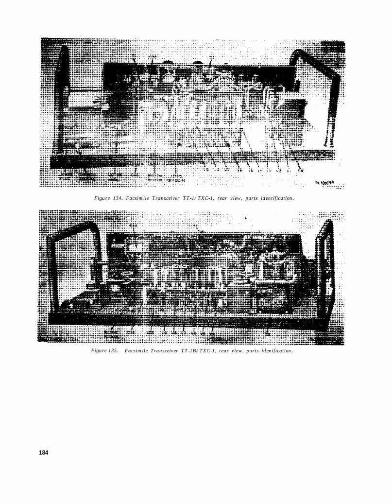
Figure 134. Facsimile Transceiver TT-1/TXC-1, rear view, parts identification.
Figure 135. Facsimile Transceiver TT-1B/TXC-1, rear view, parts idenification.
184

Figure 136.
Figure 137. Facsimile Transceivers TT-1D/TXC-1 and TT-1E/TXC-1, rear view, parts identification.
185

Figure 138. Facsimile Transceiver TT-1F/TXC-1, rear view, parts identification.
Figure 139. Facsimile Transceivers TT-1/TXC-1 and TT-1A/TXC-1, regulator panel,bottom view, parts identification.
186

Figure 140. Facsimile Transceivers TT-1D/TXC-1, TT-1E/TXC-1, and TT-1F/TXC-1,regulator panel, bottom view, parts identification.
Figure 141. Facsimile Transceiver TT-1/TXC-1, rear of front panel, parts identification.
187

Figure 142. Facsimile Transceiver TT-1A/TXC-1, rear of front panel, parts identification.
188

Figure 143. Facsimile Transceivers TT-1B/TXC-1 and TT-1C/TXC-1, rear of front panel, parts identification.
189

Figure 144. Facsimile Transceivers TT-1D/TXC-1, TT-1E/TXC-1, and TT-1F/TXC-1, rear of front panel, partsidentification.
Figure 145. Unsealed fork oscillator unit, parts identification.
190

Figure 146. Sealed fork oscillator unit,and AN/TX C-1B,
Facsimile Sets AN/TXC-1, AN/TXC-1A,
parts identification.
Figure 147. Sealed fork oscillator, Facsimile SetsAN/TXC-1C and AN/TXC-1D, parts identification.
191
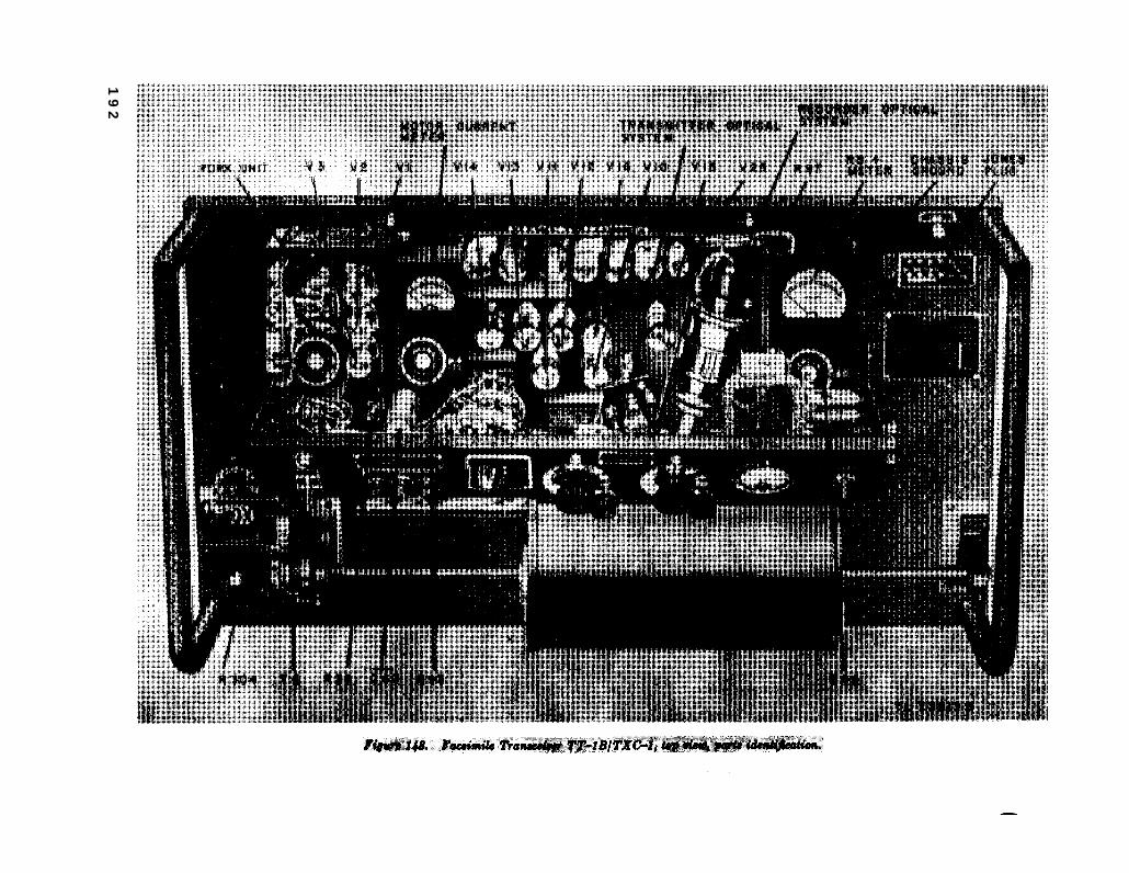
Figure 148.
19
2

Figure 149. Facsimile Transceiver TT-1C/TXC-1, top view, parts identification.
193

TM
2258-C2-15
194

195

Figure 152. Rectifier Power Unit PP-86/TXC-1, bottom view, parts identification.
196

Figure 153. Rectifier Power Unit PP-86A/TXC-1, furnished on Order No. 21751-Phila-50,top view, parts identification. Also Rectifier Power Unit PP-86E/TXC-1
Figure 154. Rectifier Power Unit PP-86A/ TXC-1, furnished on OrderNo. 21761-Phila-50, bottom view, parts identification.
197

Figure 155. Rectifier Power Unit PP-86B/TXC-1, bottom view, parts identification.
198

Figure 156.
199

CHAPTER 7
SHIPMENT AND LIMITED STORAGE AND DEMOLITIONENEMY USE
TO PREVENT
Section I. SHIPMENT AND LIMITED STORAGE
143. Disassembly or limited storage depends on the material avail-Disassembly of Facsimile Set AN/TXC-1(*) able and the conditions under which the equip-
consists of removing cabling between components ment is to be shipped or stored. Cushion theand disconnecting the transmission lines. All con- developer bottles and thermometer adequately.trols should be placed in the off or standby posi- Whenever practicable, place a dehydrating agenttion, and any parts which may become loose dur- such as silica gel inside the boxes. Protect theing shipment should be properly secured to prevent boxes with a waterproof paper barrier. Seal thedamage to the equipment. seams of the paper barrier with waterproof sealing
144. Repacking(fig. 7)
The exact procedure in repacking for
Section II. DEMOLITION
compound or tape. Pack the protected boxes ina padded wooden case, providing at least threeinches of excelsior padding or similar material
shipment between the paper barrier and the packing case.
OF MATERIEL TO PREVENT ENEMY USE
145. General
The demolition procedures outlined in para-graph 146 will prevent the enemy from using orsalvaging this equipment. Demolition of theequipment will be accomplished only upon orderof the commanding officers.
146. Methods of Destruction
a. Smash. Smash the controls, tubes, coils,switches, capacitors, transformers, headsets andbottles; use sledges, axes, handaxes, pickaxes,hammers, crowbars, or heavy tools.
b. Cut. Cut cords, headsets wiring, and otherwiring; use axes, handaxes, or machetes.
c. Burn. Burn cords, resistors, capacitors, wir-ing, and technical manuals; use gasoline, kerosene,oil, flame throwers, or incendiary grenades.
d. Bend. Bend panels, cabinet, chassis, andtable.
e. Explosives. If explosives are necessary, usefirearms, grenades, or TNT.
f. Disposal. Bury or scatter the destroyedparts in slit trenches, fox holes, or other holes,or throw them into streams.
g. Destroy. Destroy everything.
2 0 0

Figure 157.
20
1

Figure 158. Rectifier Power Unit PP-86/TXC-1, schematic diagram.
2 0 2

Figure 159. Rectifier Power Unit PP-86A/TXC-1, furnished previous to Order No. 21751-Phila-50, schematic diagram.
2 0 3

Figure 160.
TM
2258-34
204

Figure 161.
TM
2258-C4-33
205

Figure 162. Modification of a portion of schematic ofRectifier Power Unit PP-86(*)/TXC-1.
2 0 7
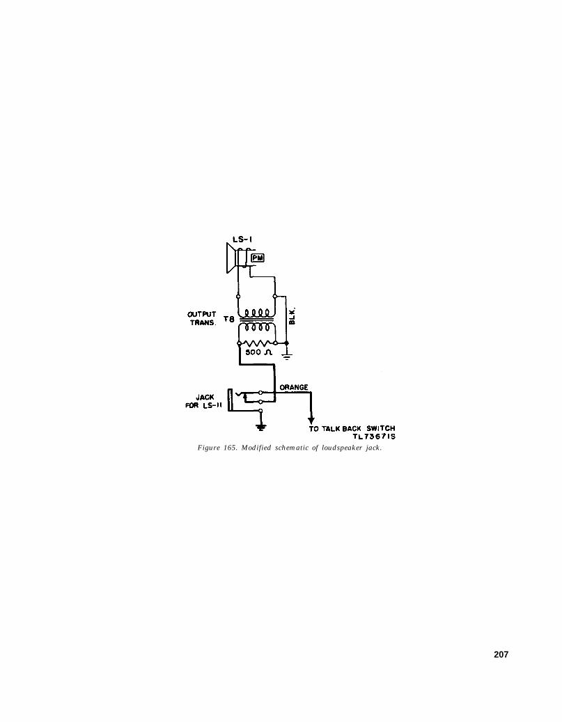
Figure 165. Modified schematic of loudspeaker jack.
207

Figure 170. Automatic stop circuit Facsimile Transceiver TT-1(*)/TXC-1.
2 0 8

Figure 172..
209

Figure 173. Sealed fork oscillator unit, wiring diagram.
210

Figure 174.
TM 2258-C4-32
211

Figure 175.
TM
2258-37
212

TM
2254-C2-32
Figure 176.213

Figure 177.
214

Figure 178. Facsimile Transceivers TT-1/TXC-1 and TT-1A/TXC-1, regulator panel wiring diagram.
215

Figure 179. Facsimile Transceivers TT-1B/TXC-1, TT-1C/TXC-1, TT-1D/TXC-1, and TT-1E/TXC-1, regulator panelwiring diagram.
216

Figure 180. Facsimile Transceiver TT-1F/TXC-1, regulator panel wiring diagram.
217

Figure 182.
218

Figure 189.
219

Figure 190.
220

Figure 191.
221

222Figure 194.

223Figure 195.


INDEX
Para-Para- graphgraph
Application of Facsimile Set AN/TXC-1(* ) - - - - - - - - - - - - - - - - - - - - - - - - - - - - - - -
Auxiliary equipment:Converter CV-2C/TX:
Application:Connections-- - - - - - - - - - -R e c e i v i n g - - - - - - - - - - - - -Transmitting - - - - - - - - - - - - -
Block diagram- - - - - - - - - - - - - - -Exciter Unit O-5B/FR:
Application - - - - - - - - - - - - - - - - - - -General- - - - - - - - - - - - - - - - - - - -Operation- - - - - - - - - - - - - -RF Oscillator O-86/FRT - - - - - - -
27b82f
Block diagrams - - - - - - - - - - - - - - - - - - - - - - -Bridge modulator, simplified - - - - - - - - - - - -Brushes- - - - - - - - - - - - - - - - - - - - - - - - - - - -B+ voltage regulator:
Repair- - - - - - - - - - - - - - - - - - - - - - - - - --Theory---- - - - - - - - - - - - - - - - - - - - - - - -Trouble analysis - - - - - - - - - - - - - - - - - - -
Capacitors:Emergency parts replacements - - - - - -Prevenetive maintenance - - - - - - - -
4
59a59c59b59
63616462
6674a
104g
12079
100
125b43
CARBON MIKE jack - - - - - - - - - - - - - - - - - 14c(4)Carrier shift modulation - - - - - - - - - - - - - - - - 4b(3)Characteristics, technical:
Facsimile Transceiver TT-1(*)/TXC-1- - - - - - - - - - - - - - - - - - - - - - - -
Rectifier Power Unit PP-86(*)/TXC-1- - - - - - - - - - - - - - - - - - - - - - - -
Checking filament and B+ circuits forshorts----- - - - - - - - - - - - - - - - - - - - - - - - - -
Circuits, Facsimile Set AN/TXC-1(*)/- - - -Clamp bar, removal - - - - - - - - - - - - - - - - - - -Clutch:
Disassembly and lubrication - - - - - - - -Operation - - - - - - - - - - - - - - - - - - - - - - - -Parts description:
Fascimile Sets AN/TXC-1, AN/TXC-1A, and AN/TXC-1B - -
Fascimile Set AN/TXC-1C - - - - -Repair and adjustment - - - - - - - - - - - -
Components:Description - - - - - - - - - - - - - - - - - - - - - - -Table - - - - - - - - - - - - - - - - - - - - - - - - - - --
Condenser lens - - - - - - - - - - - - - - - - - - - - - - -Connections:
Connections of Facsimile Set AN/TXC-1(*) - - - - - - - - - - - - - - - - - - - - - -
Radio circuits - - - - - - - - - - - - - - - - - - - - -Terminal panel - - - - - - - - - - - - - - - - - - - -Wire lines - - - - - - - - - - - - - - - - - - - - - - - -
5a
5b
8666a
107f
13b77e
106c106d
106
87
109
14b18
14c15
Page
4
58585858
60596160
6585
151
172100143
1734618
4
6
6
11065
155
1597
153153150
77
158
15221819
CONTRAST control (R45):Description and use - - - - - - - - - - - - - - - -Setting GAIN and CONTRAST con-
trols - - - - - - - - - - - - - - - - Control voltage amplifier - - - - - - - - - - - - - -Controls and their uses:
Facsimile Set AN/TXC-1(*), con-trols - - - - - - - - - - - - - - - - - - - - - - - - ---
General--- - - - - - - - - - - - - - - - - - - - - - - -Converter CV-2C/TX - - - - - - - - - - - - - - - - -Cords and leads - - - - - - - - - - - - - - - - - - - - - - -Coupling coils:
Preventive maintenance - - - - - - - - - - - -UC coupling unit - - - - - - - - - - - - - - - - -Use - - - - - - - - - - - - - - - - ----
22
2221598b
438e
15e
Darkroom:
DB
Installation - - - - - - - - - - - - - -- - - - - - - - - 19Photographic processing:
Common photographic faults - - - - 32cDarkroom operations - - - - - - - -- - - 32bDeveloper and hypo solutions - - - - 32a
Preventive maintenance, photo-graphic equipment - - - - - - -- - - - - - - - 43
METER:Amplifier, theory - - - - - - - - - - - - - - - - 75d(2)Circuit:
Repair and adjustment - - - - - - - - - 119Trouble analysis - - - - - - - - - - - - - - - 94
Preventive maintenance - - - - - - - - - - - 43Demolition:
General - - - - - - - - - - - - - - - - - - - - - - - - - - 145Methods of destruction - - - - - - - - - - - - - 146
Department of the Army Lubrication Or-ders - - - - - - - - - - - - - - - - - - - - - - -------- 44
Description of components:Cords and leads - - - - - - - - - - - - - - - - - - - 8dFacsimile Transceiver TT-1(*)/TXC-
1 - - - -- - - - - - - - - - - - - - - - - --------- 8aLoudspeaker LS-11 - - - - - - - - - - - - - - - - 8fRecording paper - - - - - - - -- - - - - - - - - - - 8gRectifier Power Unit PP-86(*)/TXC-
1 - - - - - - - - - - - - - - - - - - - - - - - - ------ 8bTable MT-252(*)/TXC-1 - - - - - - - - - - 8cUC coupling unit - - - - - - - - - - - - - - - - 8e
Developer and hypo solutions - - - - - - - - - - - - - 32aDifference in models:
Fork oscillator unit - - - - - - - - - - - - - - - - 10aRectifier Power Unit PP-86(*)/TXC-
1 - - - - - - - - -- - - - - - - - - - - - - - ------- 10eResistance and capacitance values - - - - 10dSynchronous motor - - - - - - - - - - - -- - - - 10cTable MT-252A/TXC-1 - - - - - - - - - -- 10fTalk-back circuit - - - - - - - - - - - -- - - - - - 10bTransceiver difference - - - - - - - - - - - - 10g
Page
24
33105
242458
8
468
20
23
403939
46
91
17214146
200200
49
8
788
888
39
10
1111121112
225

Direct recording:Receiving copy of Timefax paper -----Receiving on Teledeltos paper -------Transmitting positive -------------
Disassembly --------------------------Dog latch cam plate --------------------Drum:
Assembly, parts description --------Chock, removal -------------------Controls --------------------------Operation -----------------------Preventive maintenance-----------Repair and adjustment -------------Trouble analysis -------------------
Duplicating process using Timefax A paper-Rustproofing --------------------------
Electrica1 circuits ---------------------Emergency repairs and operation:
Field wire operational trouble --------Loaded cable circuit operational
troubles ------------------------Radio interference:
RECORD DIRECT----------TRANSMIT -----------------RECORD DIRECT allowances-RECORD PHOTO allowances-Recording paper substitutes -----Parts replacements-------------Transmitting allowances --------Use of old rectifier power unit
with new transceiver---------End-of-copy limit switch ---------------Equipment:
Performance check list----------Tools and materials ----------------Tools and test --------------------Uncrating, unpacking, and checking
new equipment ------------------Exciter lamp. (See Transmitter optical
system.)Exciter lamp supply:
Repair and adjustment------------Theory---- - - - - - - - - - - - - - - - - - - - - - - -Trouble analysis------------------
Exciter Unit 0-5B/FR:Application -----------------------Description -----------------------Operation ------------------------RF Oscillator 0-86/FRT-----------
Facsimile Set AN/TXC-1(*):Application -----------------------Block diagram --------------------Controls --------------------------Description of components ----------Differences in models --------------Electrical circuits ------------------Fundamentals ---------------------Interconnections ------------------Modifications ---------------------Packaging data -------------------Purpose and use -------------------
226
Para-graph
282825
143106g
107g14a22b65b43
10790295166
131
132
130129128127133125126
13422c
583985
13
12382
102
63616462
46622
81066
65b14b
1163
Page
343431
200155
15815286446
155138
3752
65
175
175
175175175174175173174
17528
5545
109
15
173104144
60596160
46524
7106564151263
Facsimile Set AN/TXC-1(*)-ContinuedRunning spares -------------------Siting ----------------------------Stage names ----------------------Technical characteristics ---------
Facsimile Set AN/TXC-1:Modifications ---------------------Motor amplifier driver -------------Synchronous motor ------------------Table of components ---------------
Facsimile Set AN/T XC-1A:Modifications ---------------------Motor amplifier driver --------------Synchronous motor ----------------Table of components ---------------
Facsimile Set AN/TXC-1B:Motor amplifier driver------------Synchronous motor ----------------Table of components ---------------
Facsimile Set AN/TXC-1C:Motor amplifier driver --------------Multivibrator ---------------------Synchronous motor -----------------Table of components ---------------
Facsimile Transceiver TT-1 (*)/TXC-1:Description of components ----------Performance check:
Receiving, direct recording -----Receiving, photographic record-
ing --- - - - - - - - - - - - - - - - - - - - - -Transmitting -----------------
Stage names ----------------------Technical characteristics -----------
Field maintenance:Lubrication:
Chart ------------------------Clutch -----------------------Drive shaft bearings---------Lead-screw bearings -----------Motor --- - - - - - - - - - - - - - - - - - - - -
Field wire operational troubles ----------Final testing --------------------------First lamp amplifier -------------------First signal amplifier ------------------Fork oscillator unit:
Differences in models --------------Repair and adjustment ------------
Pa.agraph
91267
5
1171737a
1171737b
71737c
7172737d
8a
58
5858675a
13513613713813913114082a75a
10a112
Theory -------------------------- 69,70Trouble analysis -------------------
Fork oscillator unit (sealed):Fork amplifier driver ---------------Fork output amplifier--------------Second fork amplifier-------------
Fork oscillator unit (unsealed):Fork driver ---------------------Fork input amplifier ------------Fork output buffer ----------------Tuning fork ----------------------
Forms and records ---------------------Frequency shift transmission------------Fundamentals of Facsimile-------------Fuses - - - - - - - - - - - - - - - - - - - - - - - - - - - - - - - -
92
70b70d70c
69c69b69d69a
217c65
14b
Page
91570
6
127883
7
127783
7
7783
7
778383
7
7
55
555570
6
17617617617717717517810487
10167
72, 75140
767676
73727372
3226415

Para-graph
GAIN control (R59 and RH60) ----------- 22Gelatin pad, use of for duplicating ------- 30b
Index of cooperation ------------------- 23aIndividud unit performance ------------ 140Installation:
Connection ---------------------- 14, 15Darkroom------------------------ 19Siting ---------------------------- 12
Jag or jitters -------------------------- 90b
Keyway ------------------------------ 108c
Lamp:Bracket, repair and adjustment ----- 109dDiver --------------------------- 82bSupply:
Repair and adjustment-------- 123Theory----------------------- 82Trouble analysis . . . . . . . . . . . . . 102
Load-screw and drum:Lubrication ----------------------- 46Parts description ------------------ 108eRepair and adjustment ------------- 108Trouble analysis ------------------- 90
LIMIT switch------------------------ 22cLINE binding posts------------------- 14c(3)Line feed pattern ---------------------- 90aLINE jack---------------------------- 14c(6)Loaded cable operational troubles ------ 132Loading drum ----------------------- 24b, 30aLoudspeaker LS-11 -------------------- 8fLubrication:
Approved lubricant for FacsimileSet AN/TXC-1(*)--------------- 45
Department of the Army LubricationOrders ------------------------- 44
Disassembly and lubrication of equip-ment at field maintenance level:
Clutch ----------------------- 136Driver shaft bearings ---------- 137Lead-screw bearings ----------- 138Lubrication chart ------------- 135Motor ----------------------- 139
Techniques ----------------------- 46Unusual conditions ---------------- 47
Mechanical system -------------------- 66bMeter amplifier ---------------------- 75d(2)Models, differences -------------------- 10Modifications:
MWO SIG 11-375B-1------------ 11aMWO SIG 11-2258-1------------ 11bMWO SIG 11-2258-2---------------- 11cMWO SIG 11-2258-3---------------- 11dMWO SIG 11-2258-5--------------- 11eMWO SIG 11-2258-6-------------- 11fMWO SIG 11-2258-7---------------- 11g
Modulator buffer:Sealed fork Oscillator-------------- 70d(2)Unsealed fork oscillator------------ 69d(1)
Moistureproofing and fungiproofing afterrepairs----------------------------- 49
Page2438
29178
15, 192315
138
158
159105
173104144
501581581382818
13818
17530, 38
8
50
49
176176177176177
5050
659110
12121212121414
7673
52
Para-graph
Motor (see also Synchronous motor):Page
Amplifier buffer:Sealed fork Oscillator ---------- 70d(1) 70Unsealed fork oscillator -------- 69d(1) 73
Amplifier driver and output stages- 71 77Amplifier, repair and adjustment--- 91, 111 141, 166Disassembly --------------------- 143 Modification --------------------- 11Preventive maintenance ------------------ - 43Speed control switch (S4)----------- 22Worm and gear lubrication -------------- 46
MOTOR JACK ---------------------- 18c(7)Multivibrator ------------------------- 72MWO SIG 11-375B-1 ---------------- 11aMWO SIG 11-2258-1 ------------------ 11bMWO SIG 11-2258-2--------------- 11eMWO SIG 11-2258-3----------- 11dMWO SIG 11-2258-5--------------- 11eMWO SIG 11-2258-6-------------- 11fMWO SIG 11-2258-7------------------- 11gNegative photographic recording -------- 23d(3)
Objective lens ------------------------- 109fObjective lens barrel ----------------- 109b(6)Operation:
Coordination between operators -----Arctic climates --------------------Desert climates -------------------Photographic processing-----------Piece-by-piece transmission ---------Preparatiom ----------------------Receiving copy on Timefax paper---Receiving on Teledeltos paper ------Receiving, photographic recording---Transmitting, general------------Transmitting negative -------------Transmitting positive for direct re-
coding -------------------------Transmitting positive for positive
photographic recording ----------Tropical climates------------------Under unusual conditions ----------Under usualS conditions -------------
Operator coordination ------------------Optical system:
Preventive maintenance------------Recorder:
Parts description --------------Repair and adjustment--------
Theory---------------------------Transmitter:
3336373231232828292427
25
2636332333
43
110f11074b
Parts description ---------- 109j and kRepair and adjustment --------- 109
Organizational tools and equipment ------ 38Packaging data ----------------------- 6Painting ------------------------------ 53Paper clamp, removal----------------- 107fParts description:
Clutch assembly:Facsimile Sets AN/TXC-1, AN/
TXC-1A, and AN/TXC-1B-- 106cFacsimile Set AN/TXC-1C----- l06d
2001246245023831212121212141430
160158
4044443938293434373033
31
3344402940
46
16616485
16215845
652
155
153153
227

Para-graph
Parts description-ContinuedDrum assembly ---- - - - - - - - - - - - - - - - 107gLead screw, dog, and bearing ------- 108aPhase magnet --------------------- 107bRecorder optical system ------------ 110dStylus holder assembly:
Facsimile Transceivers TT-1/TXG1, TT-1A/TXC-1, TT-1B/TXC-1, and TT-1C/TXC-1-------------------------- 116d
Facsimile Transceivers TT-1D/TXC-1 and TT-1E/TXC-1-- 116e
Synchronous motor ---------------- 104hTransmitter optical system:
Facsimile Sets AN/TXC-1, -1A,and -1B------ - - - - - - - - - - 109j
Facsimile Set AN/TXC-1C- ---- 109kPerformance checklist ----------------- 58Performing preventive maintenance ------ 43Permanent installation ---------------- 18d(1)Phase magnet:
Operation ------------------------ *96cParts description ------------------ 104lRepair and adjustment ---- -------- 104j
PHASE switch ----------------------- 22, 76aPhasing:
Amplifier ------------------------- 96Circuit:
Repair and adjustment --------- 113Theory ----------------------- 77
Error --------------------------- 77d(1)Pulses ---------------------------- 25cReceiver ------------------------- 28c
PHONES jack----------------------- 14c(1)Photocell:
Circuit:Theory ----------------------- 74Trouble analysis --------------- 97
Lens barrel ----------------------- 109iOptical system -------------------- 74bRepair and adjustment ------------- 114Simplified bridge modulator circuit-- 74a
Photographic:Equipment ----------------------- 19Equipment, preventive maintenance- 43Faults --------------------------- 32cProcessing ------------------------ 32Recording ------------------------ 29
Piece-by-piece transmission ------------- 31Placing copy on drum ------------------- 24bPositive photographic recording --------- 23d(2)Power ON-OFF switch (S2)------------ 22Preventive maintenance:
Definition ------------------------ 40External ------------------------- 43aTechniques:
Forms, use ------------------- 42General ---------------------- 41Performing ------------------- 43
Primary clutch ------------------------ 106aPulse amplifier ------------------------ 77c
228
Page
158158155164
169
169145
162162
554623
142148148
24, 94
142
1679597323418
8514216185
16785
234640393738303024
4546
464546
15096
Para-graph
Purpose and use----------------------- 3Radio circuits, connections ------------- 18Radio interference ------------------- 129, 130RADIO RCVR jack ----------------- 18c(2)RADIO XMTR jack -------------------- 18c(5)Receiving :
Photographic recording --------------- 30On Timefax paper ----------------- 28On Teledeltos paper (direct process)- 28
Reception, type---------------------- 23RECORD DIRECT ------------------- 22c(5)Record direct amplifier driver ---------- 75d(1)Record output amplifier------------------- 75eRecorder optical system:
Parts description ------------------ 110fRepair and adjustment -------------- 110Theory--------------------------- 75e(1)
Recording paper------------------------------- 8hRecording paper substitutes ----------- 133RECORD PHOTO-----------22c(4), 133
Page3
221752322
38343429289193
9316493
9175
28, 175Rectifier power supply --------------- 101, 121, 144, 172Rectifier Power Unit PP-86(*)/TXC-1:
Block diagra--------------------Desciption -- - - - - - - - - - - - - - - - - - - -Difference in models ---------------Stage names -----------------------Theory:
Exciter lamp supply -----------Rectifier power supply -------
Use of old rectifier power unit withnew transceiver -----------------
Repacking ----------------------------Repair and adjustments:
B+ voltage regulator --------------Clutch --- - - - - - - - - - - - - - - - - - - - - - - -DB METER circuit --------------Drum ----------------------------Exciter lamp supply ---------------Fork oscillator unit ----------------General - - - - - - - - - - - - - - - - - - - - - - - - - -Lead screw ---- - - - - - - - - - - - - - - - - - - -Motor amplifier -------------------Phasing circuit- - - - - - - - - - - - - - - - - - - -Photocell circuit -------------------Recorder optical system ------------Rectifier power supply -------------Selector switch --------------------Signal amplifier -------------------Synchronous motor unit ------------Transmitter optical system ---------
Replacing stylus in Facsimile TransceiversTT-1D/TXC-1 and TT-1E/TXC-1---
Replacing worm and gear in synchronousmotor KBA-2-----------------------
Resistors:Emergency parts replacements ------Preventive maintenance ------------
RF Oscillator 0-86/FRT ---------------Rotor bearing -------------------------Running spare -----------------------Rustproofing and painting --------------
808b
10e67b
8281
134144
120106119107119112103108111113114110121116115104109
117
105
1254362
104c9
53
1028
1270
104102
175200
172150172155172167144158166167167164172169169144158
170
149
1734660
1449
52

P a r agraph
Safelight - - - - - - - - - - - - - - - - - - - - - - - - - - - - - 19Scope -------------------------------- 1Second fork amplifier ------------------ 70cSecond signal amplifier ---------------- 75bSecondary clutch----------------- 106bSectionalization of trouble to a com-
ponent ----------------------------- 56Selector switch (S1):
Description ----------------------- 22cRepair and adjustment ------------- 116
Service upon receipt of used or recondi-tioned equipment -------------------- 20
SET RANGE ------------------------- 22c(2)Shipment and limited storage
Disassembly ---------------------- 143Repacking ------------------------ 144
Signal amplifierRepair and adjustment------------ 115Theory --------------------------- 75Trouble analysis:
RECORD DIRECT ---------- 95RECORD PHOTO ------------ 93STANDBY ------------------ 99TRANSMIT ----------------- 98
Signal meter amplifier ------------------ 75dSignal tracing:
Charts, use ----------------------- 87Exciter lamp supply --------------- 102aPhasing amplifier ------------------ 96bPhotocell circuit ------------------- 97aSignal amplifier (RECORD PHOTO)- 93a
Siting -------------------------------- 12Spares, running ----------------------- 9Stage names-------------------------- 67STANDBY --------------------------- 22STANDBY-MON-TALK switch (S5) ---- 22Start magnet:
Parts descriptoin ------------------ 104mRepair and adjustment------------- 103k
START-PHASE switch (S3), FacsimileSet AN/TXC-1C -------------------- 22
START switch (S4), Facsimile Sets AN/TXC-1C, AN/TXC-1A, and AN/TXC-1B--- - - - - - - - - - - - - - - - - - - - - - - - - - - - - - - 22
Page23
37683
151
63
28169
2328
200200
16987
141141143143
91
110144142142141
159
702424
148144
24
24Stylus holder assembly---------------- 116d, e 169, 170Stylus transformer --------------------- 116 169Subcarrier amplitude modulation -------- 17a 21Subcarrier frequency modulation.------- 17b 22Switch ------------------------------ 43 46Synchronous motor:
Differences in models -------------- 10c 11Modification ---------------------- 11 12Parts description ------------------ 104h 145Preventive maintenance ------------ 43 46Repair and adjustment------------- 104 144Starting circuit -------------------- 73b 84Theory--------------------------- 73 83
Table MT-252(*)/TXC-1 -------------- 8c 8[AG 413.44 (10 Mar 55)]
Para-graph
Talk-back circuitDescription ----------------------- 66fDifferences models -------------- 10bTheory--------------------------- 78
Talking circuits-------------------------- 16Technical characteristics- ------------- 5Teledeltos paper ----------------------- 8h(1)Temporary installation ---------------- 18d(3)Terminal blocks ----------------------- 35iTerminal panel------------------- 18cTest equipment required for final testing-- 141Tests -------------------------------- 142Third signal amplifier ------------------ 75eTimefax A paper ---------------------- 8h(2)Tools required for organizational mainte-
nance ------------------------------ 39Tools supplied with Facsimile Set AN/
TXC-1(*)- - - - - - - - - - - - - - - - - - - - - - - - - - 38Tools and test equipment --------------- 85Transformers and chokes--------------- 43Transmission, type -------------------- 23TRANSMIT ------------------------- 22Transmitter optical system ------------- 109Transmitting:
Copy ---------------------------- 25dNegative ------------------------- 27Phasing pulses --------------------- 25cPositive for direct recording ------- 25Positive for positive photographic
recording ----------------------- 26Preliminary operations ------------- 24
Trigger tube -------------------------- 77dTropicalization ------------------------ 48Troubleshooting:
Data ----------------------------- 84Chart ---------------------------- 89Equipment performance check list--- 57Procedures ----------------------- 83
Tubes and sockets --------------------- 43Tuning fork -------------------------- 69aUC coupling unit ---------------------- 8eUncrating, unpacking, and checking ----- 13Unusual conditions -------------------- 33Use of gelatin pad for duplicating ------- 30bVisual inspection ---------------------- 55Voltage and resistance measurements ---- 88Voltage regulator (see also B+ voltage
regulator)-------------------------- 79Voltage regulator rectifier -------------- 77eVoice circuits ------------------------- 14d(1)Weatherproofing:
Dustproofing ---------------------- 51Moistureproofing and fungiproofing
after repairs --------------------- 49Procedures ----------------------- 48Rustproofing and painting ---------- 53Tropical maintenance-------------- 48Winterization --------------------- 50
Wire circuits -------------------------- 4aWire lines ---------------------------- 14d
Page
69119821
69
234423
178178
909
45
45109462924
158
33333231
33309750
10913653
1084672
815403853
116
1009719
52
5250525052
419
229

BY ORDER OF THE SECRETARIES OF THE ARMY AND THE AIR FORCE:
OFFICIALJOHN A. KLEIN,
Major General, United States Army,The Adjutant General.
OFFICAL:E. E. TORO,
Colonel, United States Air Force,Air Adjutant General.
DISTRUBUTION:Active Army:
CNGB (1)Tec Svc, DA (1)Tec Svc Bd (1)CONARC (5)CONARC Bd (Incl ea Test Sec)
(1)Army AA Comd (2)OS Maj Comd (5)OS Base Comd (5)Log Comd (5)MDW (1)Armies (5)Corps (2)Tng Div (2)Ft & Cp (2)Gen & Br Svc Sch (5)SigC Sch (25)Gen Depots (2)
M. B. RIDGWAY,General, United States Army,
Chief Of Staff
N. F. TWINING,Chief of Staff, United States Air Force
SigC Sec, Gen Depots (10)SigC Depots (20)POE (2)OS Sup Agencies (2)SigC Fld Maint Shope (3)SigC Lab (5)Mil Dist (1)Units organized under following
TOE’s:7A, Inf Div (2)11-7, Sig Co Inf Div (2)11-15, Sig Bn, Corps or Abn
Corps (2)11-16A, Hq & Hq Co, Sig Bn,
Corps or Abn Corps (2)11-17A, Rad-Msg Cln Opr Co
(2)11-57, Armd Sig Co (2)
Units organised under followingTOE’s-Continued
11-95, Sig Bn-Opr (2)11-99, Msg-CenOpr Co, Sig Bn
(2)11-127, Sig Rep Co (2)11-128A, Sig Depot Co (2)11-500A (AA-Ae), Sig Svc Org
(2)11-557A, Abn Sig Co (2)11-587A Sig Base Maint Co (2)11-592A, Hq & Hq Co, Sig Base
Depot (2)11-597A, Sig Base Depot Co (2)17A Armd Div (2)57, Abn Div (2)
NG: State AG (6): units-same as Active Army except allowance is one copy to each unit.U S A R : N o n e . For explanation of abbreviations used, see SR 320-50-1.
2 3 0

Figure 193. TM 2258-C4-37

Figure 192.

Figure 188.

Figure 187.

Figure 186. Facsimile Transceiver TT-1B/TXC-1, front panel wiring diagram.

Figure 185.

Figure 184.

Figure 183.

Figure 181.

Figure 171.

Figure 169.

Figure 168.

Figure 167.

Figure166.

Figure 164.

Figure 163.


PIN: 015995-000

This fine document...
Was brought to you by me:
Liberated Manuals -- free army and government manuals
Why do I do it? I am tired of sleazy CD-ROM sellers, who take publicly available information, slap “watermarks” and other junk on it, and sell it. Those masters of search engine manipulation make sure that their sites that sell free information, come up first in search engines. They did not create it... They did not even scan it... Why should they get your money? Why are not letting you give those free manuals to your friends?
I am setting this document FREE. This document was made by the US Government and is NOT protected by Copyright. Feel free to share, republish, sell and so on.
I am not asking you for donations, fees or handouts. If you can, please provide a link to liberatedmanuals.com, so that free manuals come up first in search engines:
<A HREF=http://www.liberatedmanuals.com/>Free Military and Government Manuals</A>
– SincerelyIgor Chudovhttp://igor.chudov.com/
– Chicago Machinery Movers