National Ignition Facility SubSystem Design Requirements ...

Facility Requirements

CHAPTER THREECHAPTER THREECHAPTER THREECHAPTER THREE
To properly plan for the future of Marina Municipal Airport, it is necessary to translate fore-cast aviation demand into the speci ic types and quantities of facilities that can adequately serve the identi ied demand. This chapter uses the results of the forecasts presented in Chapter Two, as well as established planning criteria, to determine the airside (i.e., runways, taxiways, navigational aids, marking and lighting) and landside (i.e., hangars, aircraft park-ing apron, and automobile parking) facility requirements.
The objective of this effort is to identify, in general terms, the adequacy of the existing Airport facilities and outline what new facilities may be needed and when these may be needed to accommodate forecast demands. Having established these facility requirements, alternatives for providing them will be evaluated in Chapter Four - Alternatives to determine the most cost-effective and ef icient means for implementation.
The facility requirements at Marina Municipal Airport were evaluated using guidance contained in several Federal Aviation Administration (FAA) publications, including the following:
• Advisory Circular (AC) 150/5300-13A, Airport Design• AC 150/5060-5, Airport Capacity and Delay• AC 150/5325-4C, Runway Length Requirements for Airport Design• AC 150/5360-13 Planning and Design Guidelines for Airport Terminal Facilities,• Federal Aviation Regulation (FAR) Part 77, Objects Affecting Navigable Airspace• FAA Order 5090.3C Field Formulation of the National Plan of Integrated Airport Systems (NPIAS).
3-1 Draft Final - September 2015
AIRPORT MASTER PLAN – Marina Municipal Airport
FACILITY REQUIREMENTS 3-2 DRAFT FINAL – SEPTEMBER 2015
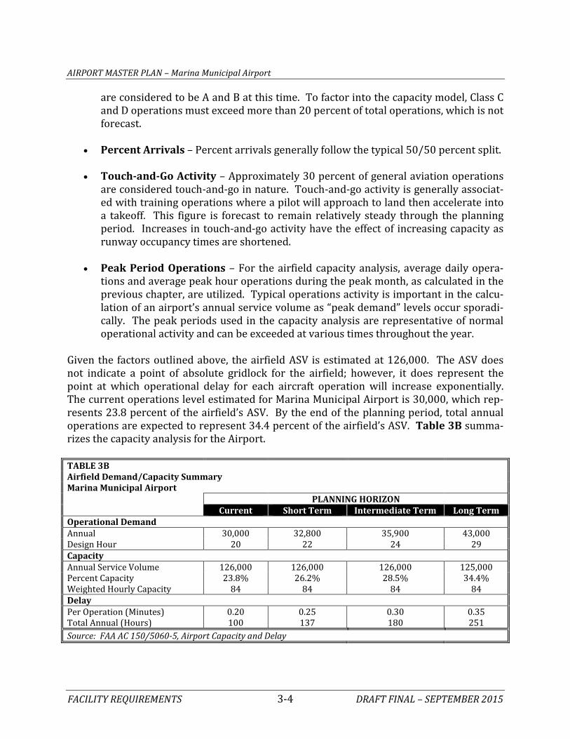
PLANNING HORIZONS An updated set of aviation demand forecasts for Marina Municipal Airport has been estab-lished. These activity forecasts include annual operations, based aircraft, fleet mix, and peaking characteristics. With this information, specific components of the airfield and landside system can be evaluated to determine their capacity to accommodate future de-mand. Cost-effective, efficient, and orderly development of an airport should rely more upon actu-al demand at an airport than on a time-based forecast figure. In order to develop a master plan that is demand-based rather than time-based, a series of planning horizon milestones have been established that take into consideration the reasonable range of aviation de-mand projections. The planning horizons are the Short Term (years 1-5), the Intermediate Term (years 6-10), and the Long Term (years 11-20). It is important to consider that the actual activity at the Airport may be higher or lower than what the annualized forecast portrays. By planning according to activity milestones, the resultant plan can accommodate unexpected shifts or changes in the area’s aviation demand by allowing airport management the flexibility to make decisions and develop fa-cilities according to need generated by actual demand levels. The demand-based schedule provides flexibility in development, as development schedules can be slowed or expedited according to demand at any given time over the planning period. The resultant plan pro-vides airport officials with a financially responsible and needs-based program. AIRFIELD CAPACITY Airfield capacity is measured in a variety of different ways. The hourly capacity measures the maximum number of aircraft operations that can take place in an hour. The airfield annual service volume (ASV) is an annual level of service that is used to define airfield congestion and delay as a runway nears its hourly capacity. The airfield’s calculated ASV is not the point at which gridlock occurs; rather, it is the point at which operational delays become exponential. Aircraft delay is the total delay incurred by aircraft using the airfield during a given timeframe. FAA Advisory Circular 150/5060-5, Airport Capacity and Delay, provides a methodology for examining the operational capacity of an airfield for planning purposes. This analysis takes into account specific factors about the airfield. These various factors are depicted in Exhibit 3A. The following describes the input factors as they relate to the Airport:
• Runway Configuration – The airfield supports a single runway, Runway 11-29, which is 3,483 feet long and 75 feet wide.
• Runway Use – Runway use is controlled by wind and/or airspace conditions. The
direction of takeoffs and landings are generally determined by the speed and direc-

Runway Configuration Runway Use Number of Exits
VMC IMC PVCVisual Meteorological Conditions Instrument Meteorological Conditions Poor Visibility Conditions
Arrivals Departures Total Annual Operations(in thousands)(in thousands)
Touch-and-Go Operations
Category A & B Aircraft(less than 12,000 lbs.)
Category D Aircraft(over 300,000 lbs.)
321
(less than 12,000 lbs.)( , ) (over 300,000 lbs.)( , )
Small Turboprop Twin Piston
Category C Aircraft(12,500 - 300,000 lbs.)
Business Jet
Regional Jet
Commuter
Commercial Jet Wide Body Jets
J F M A M J J A S O N D
7
6
5
4
3
2
1
71.7% 10.8% 17.5%
(example)
Single Engine
Exhibit 3AAIRFIELD CAPACITY FACTORS
VFR - Visual Flight Rules IRF - Instrument Flight Rules

AIRPORT MASTER PLAN – Marina Municipal Airport
FACILITY REQUIREMENTS 3-3 DRAFT FINAL – SEPTEMBER 2015
tion of the wind. It is safest for aircraft to take-off and land into the wind, avoiding a crosswind (wind that is blowing perpendicular to the travel of the aircraft) or tail-wind. It is estimated that Runway 29 accounts for 80 percent of annual activity and Runway 11 accounts for the remaining 20 percent because the primary wind direc-tion is from west to east. Over 70 percent of wind conditions are considered calm, measuring six knots or less, and Runway 29 is the designated calm wind runway so that overflights of residential neighborhoods are reduced.
• Exit Taxiways – Exit taxiways have a significant impact on airfield capacity since
the number and location of exits directly determines the occupancy time of an air-craft on the runway. For Marina Municipal Airport, those taxiway exits (located be-tween 2,000 and 4,000 feet from the runway threshold) count in the capacity de-termination. Landings to Runway 29 count as two exits and landing to Runway 11 count as one exit.
• Weather Conditions – The airport operates under visual flight rules (VFR) 71.7
percent of the time. When cloud ceilings are between 500 and 1,000 feet and visibil-ity is between one and three miles, instrument flight rule (IFR) conditions apply, which is approximately 10.75 percent of the year. Poor visibility conditions (PVC) apply when cloud ceilings are below 500 feet and visibility is below one mile. PVC conditions occur 17.55 percent of the year, primarily due to morning fog conditions. Table 3A summarizes the weather conditions between 2003 and 2013.
TABLE 3A Annual Weather Conditions
Marina Municipal Airport Condition Cloud Ceiling Visibility Observations Percent
Visual (VFR) >1,000' > 3 mi. 86,850 71.70% Instrument (IFR) ≤ 1,000' and > 500' ≤ 3 mi. and Vis > 1 mi. 13,023 10.75% Poor Visibility (PVC) ≤ 500' ≤ 1 mi. 21,258 17.55%
TOTAL 121,131 100.00%
Source: National Oceanic and Atmospheric Administration (NOAA). Ten years of data from the ASOS at Monte-rey Regional Airport from 2003-2013.
• Aircraft Mix – Aircraft mix for the capacity analysis is defined in terms of four air-
craft classes. Classes A and B consist of small and medium-sized propeller and some jet aircraft, all weighing 12,500 pounds or less. These aircraft are associated pri-marily with general aviation activity, but do include some air taxi, air cargo, and commuter aircraft. Class C consists of aircraft weighing between 12,500 and 300,000 pounds, which include most business jets and some turboprop aircraft. Class D aircraft consists of large aircraft weighing more than 300,000 pounds. The Airport does not currently experience operations by Class D aircraft. Class C opera-tions are estimated to be very infrequent primarily because Class C aircraft typically require more runway length. Therefore, for capacity consideration, all operations
AIRPORT MASTER PLAN – Marina Municipal Airport
FACILITY REQUIREMENTS 3-4 DRAFT FINAL – SEPTEMBER 2015
are considered to be A and B at this time. To factor into the capacity model, Class C and D operations must exceed more than 20 percent of total operations, which is not forecast.
• Percent Arrivals – Percent arrivals generally follow the typical 50/50 percent split. • Touch-and-Go Activity – Approximately 30 percent of general aviation operations
are considered touch-and-go in nature. Touch-and-go activity is generally associat-ed with training operations where a pilot will approach to land then accelerate into a takeoff. This figure is forecast to remain relatively steady through the planning period. Increases in touch-and-go activity have the effect of increasing capacity as runway occupancy times are shortened.
• Peak Period Operations – For the airfield capacity analysis, average daily opera-
tions and average peak hour operations during the peak month, as calculated in the previous chapter, are utilized. Typical operations activity is important in the calcu-lation of an airport’s annual service volume as “peak demand” levels occur sporadi-cally. The peak periods used in the capacity analysis are representative of normal operational activity and can be exceeded at various times throughout the year.
Given the factors outlined above, the airfield ASV is estimated at 126,000. The ASV does not indicate a point of absolute gridlock for the airfield; however, it does represent the point at which operational delay for each aircraft operation will increase exponentially. The current operations level estimated for Marina Municipal Airport is 30,000, which rep-resents 23.8 percent of the airfield’s ASV. By the end of the planning period, total annual operations are expected to represent 34.4 percent of the airfield’s ASV. Table 3B summa-rizes the capacity analysis for the Airport. TABLE 3B Airfield Demand/Capacity Summary
Marina Municipal Airport PLANNING HORIZON Current Short Term Intermediate Term Long Term Operational Demand Annual 30,000 32,800 35,900 43,000 Design Hour 20 22 24 29 Capacity Annual Service Volume 126,000 126,000 126,000 125,000 Percent Capacity 23.8% 26.2% 28.5% 34.4% Weighted Hourly Capacity 84 84 84 84 Delay Per Operation (Minutes) 0.20 0.25 0.30 0.35 Total Annual (Hours) 100 137 180 251 Source: FAA AC 150/5060-5, Airport Capacity and Delay
AIRPORT MASTER PLAN – Marina Municipal Airport
FACILITY REQUIREMENTS 3-5 DRAFT FINAL – SEPTEMBER 2015
FAA Order 5090.3B, Field Formulation of the National Plan of Integrated Airport Systems (NPIAS), indicates that improvements for airfield capacity purposes should begin to be considered once operations reach 60 to 75 percent of the annual service volume. This is an approximate level to begin the detailed planning of capacity improvements. At the 80 per-cent level, the planned improvements should be under design or construction. Based on current and projected operations developed for this study, improvements specifically de-signed to enhance capacity are not necessary during the 20-year scope of this Master Plan. AIRFIELD REQUIREMENTS As indicated earlier, airport facilities include both airfield and landside components. Air-field facilities include those facilities that are related to the arrival, departure, and ground movement of aircraft. These components include:
• Runway Design Standards • Runway Design Components • Taxiway Design Standards • Navigational Approach Aids • Lighting, Marking, and Signage
RUNWAY DESIGN STANDARDS The FAA has established several imaginary surfaces to protect aircraft operational areas and keep them free from obstructions. These include the runway safety area (RSA), run-way object free area (ROFA), runway obstacle free zone (ROFZ), and runway protection zone (RPZ). The entire RSA, ROFA, and ROFZ must be under the direct ownership of the airport sponsor to ensure these areas remain free of obstacles and can be readily accessed by maintenance and emergency personnel. RPZs should also be under airport ownership. An alternative to outright ownership of the RPZ is the purchase of avigation easements (acquiring control of designated airspace within the RPZ) or having sufficient land use control measures in plac-es which ensure the RPZ remains free of incompatible development. The various airport safety areas are presented on Exhibit 3B. Dimensional standards for the various safety areas associated with the runway are a func-tion of the type of aircraft using or expected to use the runway as well as the instrument approach capability. As identified in Chapter Two – Forecasts, the current critical design aircraft is classified as B-I. The future design aircraft may transition to those in C-II; there-fore, the design standards for both conditions are examined. Table 3C presents the FAA design standards as they apply to the runway at Airport.

AIRPORT MASTER PLAN – Marina Municipal Airport
FACILITY REQUIREMENTS 3-6 DRAFT FINAL – SEPTEMBER 2015
TABLE 3C Runway Design Standards Marina Municipal Airport Runway 11-29 Current Future RUNWAY CLASSIFICATION Runway Design Code B-I C-II Visibility Minimums 1-mile ½-mile Approach Reference Code D-VI-5000 D-VI-2400 Departure Reference Code D-VI D-VI RUNWAY DESIGN Runway Width 75 100 Runway Shoulder Width 10 10 RUNWAY PROTECTION Runway Safety Area (RSA) Width 120 500 Length Beyond Departure End 240 1,000 Length Prior to Threshold 240 600 Runway Object Free Area (ROFA) Width 400 800 Length Beyond Departure End 240 1,000 Length Prior to Threshold 240 600 Runway Obstacle Free Zone (ROFZ) Width 250 400 Length Beyond End 200 200 Precision Obstacle Free Zone (POFZ) Width NA 800 Length NA 200 Approach Runway Protection Zone (RPZ) Length 1,000 2,500 Inner Width 500 1,000 Outer Width 700 1,750 Departure Runway Protection Zone (RPZ) Length 1,000 1,700 Inner Width 500 500 Outer Width 700 1,010 RUNWAY SEPARATION Runway Centerline to: Holding Position 200 250 Parallel Taxiway 225 400 Aircraft Parking Area 200 500 Note: All dimensions in feet Source: FAA AC 150/5300-13A, Airport Design The current runway length is inadequate for many aircraft that fall within C-II. While the design standards are presented for this runway design code (RDC), they will not likely ap-ply until such a time that the runway is extended to better accommodate the larger aircraft type. In Chapter Four – Alternatives, extension possibilities will be examined and C-II de-sign standards will be applied.

Fence Line
Airport Property LineRunway Safety Area (RSA)Runway Object Free Zone (ROFZ)Runway Obstacle Free Area (ROFA)Runway Protection Zone (RPZ)
Runway 11-29 (3,483’ x 75’)
Reservation Rd.
University Dr.
Neeson Rd.
Research Dr.
Imjin
Rd.
Blan
co R
d.
N
0 1000
Scale in Feet
Photo: Google Earth 5/6/2012
North
LEGEND
Exhibit 3BSAFETY AREAS
AIRPORT MASTER PLAN – Marina Municipal Airport
FACILITY REQUIREMENTS 3-7 DRAFT FINAL – SEPTEMBER 2015
Runway Safety Area (RSA) The RSA is defined in FAA AC 150/5300-13A, Airport Design, as a “surface surrounding the runway prepared or suitable for reducing the risk of damage to airplanes in the event of undershoot, overshoot, or excursion from the runway.” The RSA is centered on the runway and dimensioned in accordance to the approach speed of the critical design aircraft using the runway. The FAA requires the RSA to be cleared and graded, drained by grading or storm sewers, capable of accommodating the design aircraft and fire and rescue vehicles, and free of obstacles not fixed by navigational purpose such as runway edge lights or ap-proach lights. The FAA has placed a higher significance on maintaining adequate RSA at all airports. Un-der Order 5200.8, effective October 1, 1999, the FAA established the Runway Safety Area Program. The Order states, “The objective of the Runway Safety Area Program is that all RSAs at federally-obligated airports…shall conform to the standards contained in Advisory Circular 150/5300-13, Airport Design, to the extent practicable.” Each Regional Airports Division of the FAA is obligated to collect and maintain data on the RSA for each runway at the airport and perform airport inspections. Currently, the RSA for the runway is 120 feet wide as centered on the runway and it ex-tends 240 feet beyond the runway ends. This standard is met at the Airport. In the future, the C-II RSA standard is 500 feet wide and it extends 1,000 feet beyond the runway ends. Runway Object Free Area (ROFA) The ROFA is “a two-dimensional ground area, surrounding runways, taxiways, and tax-ilanes, which is clear of objects except for objects whose location is fixed by function (i.e., airfield lighting).” The OFA does not have to be graded and level like the RSA; instead, the primary requirement for the ROFA is that no object in the OFA penetrates the lateral eleva-tion of the RSA. The ROFA is centered on the runway, extending out in accordance to the critical design aircraft utilizing the runway. The current ROFA standard is 400 feet wide, extending 240 feet beyond the runway ends. This standard is met at the Airport. The dimensions of the ROFA for C-II are 800 feet wide and 1,000 feet beyond the runway ends.

AIRPORT MASTER PLAN – Marina Municipal Airport
FACILITY REQUIREMENTS 3-8 DRAFT FINAL – SEPTEMBER 2015
Runway Obstacle Free Zone (ROFZ) The ROFZ is an imaginary volume of airspace which precludes object penetrations, includ-ing taxiing and parked aircraft. The only allowance for ROFZ obstructions is navigational aids mounted on frangible bases which are fixed in their location by function, such as air-field signs. The ROFZ is established to ensure the safety of aircraft operations. If the ROFZ is obstructed, the airport’s approaches could be removed or approach minimums could be increased. The current ROFZ is 250 feet wide and it extends 200 feet beyond the runway ends. This design standard is met at the Airport. For C-II, the OFZ is 400 feet wide and it extends 200 feet beyond the runway ends. A precision obstacle free zone (POFZ) is further defined for runway ends with a precision approach. The POFZ is 800 feet wide and extends from the runway threshold to a distance of 200 feet. The POFZ is in effect when the following conditions are met:
a) The runway supports a vertically guided approach; b) Reported ceiling is below 250 feet and/or visibility is less than ¾-mile; and c) An aircraft is on final approach within two miles of the runway threshold.
When the POFZ is in effect, a wing of an aircraft holding on a taxiway may penetrate the POFZ; however, neither the fuselage nor the tail may infringe on the POFZ. The POFZ standards do not currently apply to either end of the runway; however, a preci-sion instrument approach may be considered in conjunction with improvements to the runway, which would necessitate consideration of the POFZ. Runway Protection Zones (RPZ) The RPZ is a trapezoidal area centered on the runway, typically beginning 200 feet beyond the runway end. The RPZ has been established by the FAA to provide an area clear of ob-structions and incompatible land uses in order to enhance the protection of people and property on the ground. The RPZ consists of the “central portion of the RPZ” and the “con-trolled activity” area. The central portion of the RPZ extends from the beginning to the end of the RPZ, is centered on the runway, and is the width of the ROFA. The controlled activity area is any remaining portions of the RPZ. The dimensions of the RPZ vary according to the visibility minimums serving the runway and the type of aircraft (design aircraft) oper-ating on the runway.
AIRPORT MASTER PLAN – Marina Municipal Airport
FACILITY REQUIREMENTS 3-9 DRAFT FINAL – SEPTEMBER 2015
While the RPZ is intended to be clear of incompatible objects or land uses, some uses are permitted with conditions and other land uses are prohibited. According to AC 159/5300-13A, the following land uses are permissible within the RPZ:
• Farming that meets the minimum buffer requirements; • Irrigation channels as long as they do not attract birds; • Airport service roads, as long as they are not public roads and are directly con-
trolled by the airport operator; • Underground facilities, as long as they meet other design criteria, such as RSA re-
quirements, as applicable; and • Unstaffed navigational aids (NAVAIDs) and facilities, such as required for airport fa-
cilities that are fixed-by-function in regard to the RPZ. Any other land uses considered within RPZ land owned by the airport sponsor must be evaluated and approved by the FAA Office of Airports. The FAA has published Interim Guidance on Land Uses within a Runway Protection Zone (9.27.2012), which identifies sev-eral potential land uses that must be evaluated and approved prior to implementation. The specific land uses requiring FAA evaluation and approval include:
• Buildings and structures including , but are not limited to: - residences - schools - churches - hospitals or other medical care facilities - commercial/industrial buildings
• Recreational land use (examples include, but are not limited to: golf courses, sports fields, amusement parks, other places of public assembly, etc.)
• Transportation facilities. Examples include, but are not limited to: - Rail facilities - light or heavy, passenger or freight
- Public roads/highways - Vehicular parking facilities • Fuel storage facilities (above and below ground) • Hazardous material storage (above and below ground) • Wastewater treatment facilities • Above-ground utility infrastructure (i.e., electrical substations), including any type
of solar panel installations. The Interim Guidance on Land within a Runway Protection Zone states, “RPZ land use com-patibility also is often complicated by ownership considerations. Airport owner control over the RPZ land is emphasized to achieve the desired protection of people and property on the ground. Although the FAA recognizes that in certain situations the airport sponsor may not fully control land within the RPZ, the FAA expects airport sponsors to take all pos-sible measures to protect against and remove or mitigate incompatible land uses.”

AIRPORT MASTER PLAN – Marina Municipal Airport
FACILITY REQUIREMENTS 3-10 DRAFT FINAL – SEPTEMBER 2015
Currently, the RPZ review standards are applicable to any new or modified RPZ. The fol-lowing actions or events could alter the size of an RPZ, potentially introducing an incom-patibility:
• An airfield project (e.g., runway extension, runway shift); • A change in the critical design aircraft that increases the RPZ dimensions; • A new or revised instrument approach procedure that increases the size of the RPZ;
and/or • A local development proposal in the RPZ (either new or reconfigured).
The Interim Guidance only addresses the introduction of new or modified land uses to an RPZ and proposed changes to the RPZ size or location. Airport sponsors must continue to remove or mitigate the risk of any existing incompatible land uses in the RPZ as practical. While it is still necessary for the airport sponsor to take all reasonable actions to meet the RPZ design standard, FAA funding priority for certain actions, such as relocating existing roads in the RPZ, will be determined on a case-by-case basis. The RPZ serving the approach to Runway 29 remains entirely on airport property; howev-er, an unimproved gravel road does cross the northeast corner of the RPZ. This road pro-vides the only access to two residences located immediately north of airport property. The road also affords access to the FAA ASR-8 Lease Parcel under terms of a lease entered into on January 13, 1999, and to the Department of the Navy to the Doppler Radar Wind Profiler facility, under terms of a Grant of Easement made on October 15, 1996. The RPZ serving Runway 11 is on airport property and it fully meets design standard. The dimensions of the RPZ will change in size if there are changes in the design aircraft and/or the instrument approach capabilities. Table 3D presents the dimensions of the current and potential future RPZs. TABLE 3D Runway Protection Zones
Marina Municipal Airport
Current Condition Potential Future Condition Visibility Minimum 1-mile 1-mile 1-mile ¾-mile ½-mile Airport Reference Code B-I B-II C-II C-II C-II Inner Width 500 500 500 1,000 1,000 Outer Width 700 700 1,010 1,510 1,750 Length 1,000 1,000 1,700 1,700 2,500 All dimensions in feet. Source: FAA AC 150/5300-13A, Airport Design As can be seen from the table, both the length and the width of the RPZs will change if the critical aircraft transitions from B-Ito AAC C. The dimensions also change if the instrument approach capability is improved. These possible changes in the size of the RPZ will be con-sidered in conjunction with possible runway improvements in the Alternatives chapter.
AIRPORT MASTER PLAN – Marina Municipal Airport
FACILITY REQUIREMENTS 3-11 DRAFT FINAL – SEPTEMBER 2015
Runway/Taxiway Separation The design standards for the separation between runways and parallel taxiways are a func-tion of the critical design aircraft and the instrument approach visibility minimum. The separation standard for RDC B-I with 1-mile visibility minimums is 225 feet from the run-way centerline to the parallel taxiway centerline. Taxiway B is separated by 530 feet from the runway, thus meeting design standard. In the future, if the airport transitions to C-II, the runway taxiway separation for a 1-mile instrument approach visibility minimum is 300 feet. If the visibility minimum is lower than ¾-mile, then the separation standard is 400 feet. RUNWAY DESIGN COMPONENTS The adequacy of the existing runway at the Airport has been analyzed from a number of perspectives, including runway orientation, runway length, runway width, and pavement strength. This information will identify the adequacy of the runway system and indicate if improvements to the runway system are necessary. Runway Orientation The Airport is currently served by Runway 11-29 which is 3,483 feet long and is orientated generally in an east to west manner. For the operational safety and efficiency of an airport, it is desirable for the primary runway to be oriented as close as possible to the direction of the prevailing wind to reduce the impact of wind components perpendicular to the direc-tion of travel of an aircraft that is landing or taking off. FAA AC 150/5300-13A, Airport Design, recommends that a crosswind runway be made available when the primary runway orientation provides for less than 95 percent wind coverage for specific crosswind components. The 95 percent wind coverage is computed on the basis of the crosswind component not exceeding 10.5 knots (12 mph) for RDC A-I and B-I, 13 knots (15 mph) for RDC A-II and B-II, and 16 knots (18 mph) for RDC A-III, B-III, C-I through C-III, and D-I through D-III. The National Oceanic Atmospheric Administration (NOAA) National Climatic Data Center captures weather data from certain weather sensors around the country. The closest weather sensor reporting to NOAA is located at Monterey Regional Airport. Ten years of data regarding wind speed and direction was obtained from the Monterey Regional Airport weather sensor and is used to analyze the wind patterns in the region. A total of 121,131 observations of wind speed, direction and visibility were made.

AIRPORT MASTER PLAN – Marina Municipal Airport
FACILITY REQUIREMENTS 3-12 DRAFT FINAL – SEPTEMBER 2015
Runway 11-29 provides 98.23 percent wind coverage for 10.5 knot crosswinds, 99.19 per-cent coverage at 13 knots, and 99.86 percent at 16 knots. Runway 11-29 provides for greater than 95 percent wind coverage in both all-weather and IFR conditions. As a result, a crosswind runway is not required. Exhibit 3C presents the all-weather and instrument flight rule (cloud ceilings of less than 1,000 feet and/or visibility of less than 3 miles) wind rose for the Airport. Runway Length AC 150/5325-4B, Runway Length Requirements for Airport Design, provides guidance for determining runway length needs. A draft revision of this AC is currently available (150/5325-4C) and the FAA is utilizing the draft revision in most cases when evaluating runway length needs for airports. This runway length analysis will consider the recom-mendations from both versions. The determination of runway length requirements for is based on five primary factors:
• Mean maximum temperature of the hottest month • Airport elevation • Runway gradient • Critical aircraft type expected to use the runway • Stage length of the longest nonstop destination (specific to larger aircraft)
The mean maximum daily temperature of the hottest month for the Airport is 68.9 degrees Fahrenheit (F), which occurs in August. The airport elevation is 137 feet above mean sea level (MSL). The gradient of the runway is 0.1 percent which conforms to FAA design standards for gradient. The RDC for Runway 11-29 is B-I). Aircraft stage length can vary, but for planning purposes it is common to utilize increments of 500 miles. There is not a direct relationship between the classification of the design aircraft (e.g., B-II, C-II) and runway length as airplanes operate on a wide variety of available runway lengths. The suitability of the runway length is governed by many factors including elevation, tem-perature, wind, aircraft weight, wing flap settings, runway condition (wet or dry), runway gradient, vicinity airspace obstructions, useful load, and any special operating procedures. Airport sponsors can pursue policies that can maximize the suitability of the runway length. Policies, such as area zoning and height and hazard restricting, can protect an air-port’s runway length. Airport ownership (fee simple or easement) of land leading to the runway ends can reduce the possibility of natural growth or man-made obstructions. Planning of runways should include an evaluation of aircraft types expected to use the air-port, or a particular runway now and in the future. Future plans should be realistic and supported by the FAA-approved forecasts and should be based on the critical design air-craft (or family of aircraft).

NORTH
Exhibit 3CWINDROSE

AIRPORT MASTER PLAN – Marina Municipal Airport
FACILITY REQUIREMENTS 3-13 DRAFT FINAL – SEPTEMBER 2015
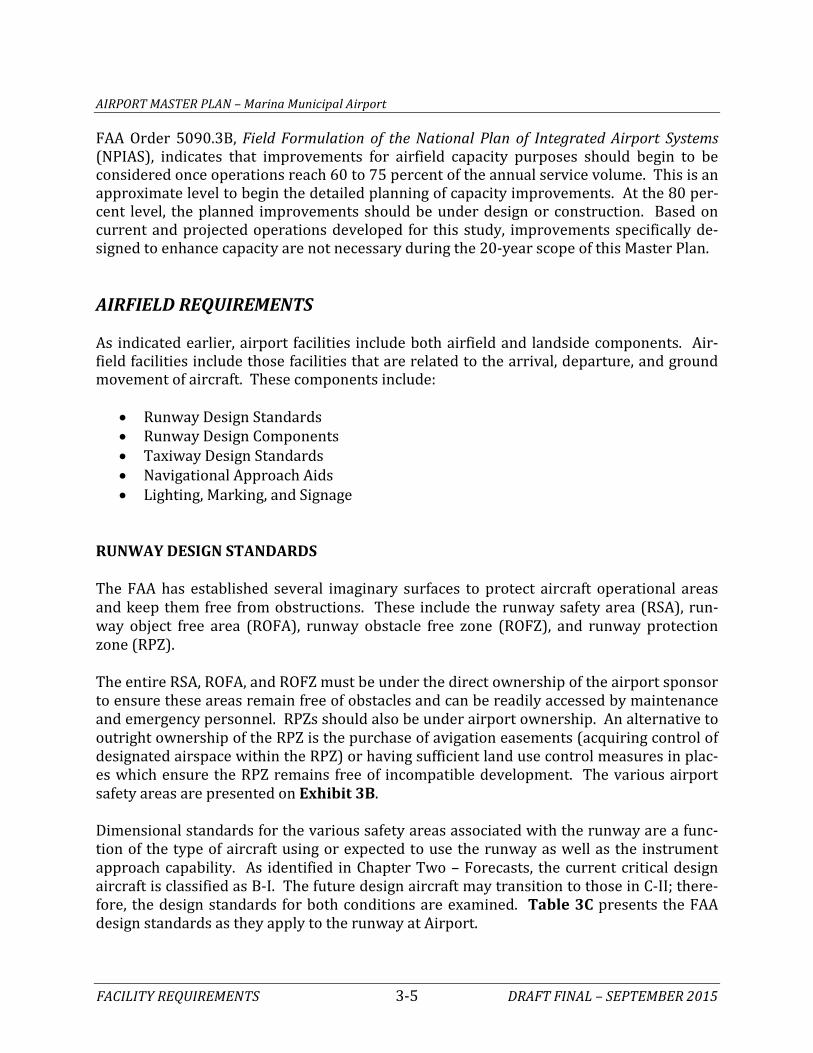
In 2013, the Airport completed a Runway Extension Justification Study. This study conclud-ed that current activity at the Airport justified an immediate 417-foot extension of the runway to 3,900 feet. In the future, the runway was recommended to be incrementally ex-tended first to 5,000 feet and then ultimately to 5,800 feet. The possible need for a 5,000-foot runway was supported by the minimum runway length requirements of the converted A-10 jet which CIRPAS plans to base at the Airport. The ultimate extension to 5,800 feet was based on the needs of business jets under heavy loading conditions. The current ALP for the Airport shows an ultimate runway length of 5,200 feet. The 2008 Airport Master Plan indicates this length was to accommodate large business jets at 60 per-cent useful load with a design aircraft in airport reference code C-II. Current Runway Length Analysis The current and new draft version of the runway length AC provide the same methodology for determining recommended runway lengths for aircraft weighing less than 12,500 pounds (small aircraft). These aircraft conduct the vast majority of operations at the Air-port. According to the AC, to accommodate 95 percent of small aircraft with less than 10 passenger seats, a runway length of 2,900 feet is recommended. To accommodate 100 per-cent of these small aircraft, a runway length of 3,400 feet is recommended. For small air-craft with 10 or more passenger seats, a runway length of 3,900 feet is recommended. To fully accommodate the current critical design aircraft (B-I) for the Airport, a runway length of 3,900 feet is recommended. Exhibit 3D presents the runway length analysis for deter-mining the current need at the Airport. The Alternatives chapter will examine the options for extending the runway to at least 3,900 feet in the short term planning horizon (the next five years). Future Runway Length Analysis The major difference between the current version of the runway length AC and the new draft version is the methodology for determining runway length requirements for general aviation jet powered aircraft. Table 3E presents the runway length recommendations for general aviation jet aircraft based on the current AC. Two categories of general aviation jet aircraft are identified; those making up 75 percent of the national fleet and those making up 100 percent of the national fleet. The 75 percent category includes most small and some medium sized general aviation jets. Examples in-clude Cessna Citation jets (models 500, 510, 525, 550, 560, 650), Lear jets (models 31, 35, 45), Beechjet 400, and Falcon jets (models 10, 20, 50). The 100 percent category includes the remaining medium and all large general aviation jets. Examples include Cessna Citation

AIRPORT MASTER PLAN – Marina Municipal Airport
FACILITY REQUIREMENTS 3-14 DRAFT FINAL – SEPTEMBER 2015
jets (models 650, 680, X), Lear jets (models 55, 60), Hawker jets (models 800XP, 1000, 4000), and Challenger 600s. TABLE 3E Runway Length Requirements
Marina Municipal Airport
Airport Elevation 137 feet above mean sea level
Average High Monthly Temp. 68.9 degrees (August)
Runway Gradient Zero effective runway gradient
Fleet Mix Category
Raw Runway Length from
FAA AC
Runway Length With Gradient
Adjustment
Wet Surface Landing Length for
Jets (+15%)*
Final Runway Length
75% of fleet at 60% useful load 4,568' 4,568' 5,253' 5,300' 100% of fleet at 60% useful load 4,785' 4,785' 5,500' 5,500' 75% of fleet at 90% useful load 5,775' 5,775' 6,641' 6,700' 100% of fleet at 90% useful load 6,906' 6,906' 7,000' 7,000' *Max 5,500' for 60% useful load and max 7,000' for 90% useful load in wet conditions Source: FAA AC 150/5325-4B, Runway Length Requirements for Airport Design. As shown in Table 3E, to accommodate 75 percent of the general aviation jet fleet at 60 percent useful load, a runway length of 5,300 feet is recommended. To accommodate 100 percent at 60 percent useful load, a runway length of 5,500 feet is recommended. To ac-commodate 75 percent of the general aviation jet fleet at 90 percent useful load, a runway length of 6,700 feet is recommended, and for 100 percent at 90 percent useful load, a length of 7,000 feet is recommended. The FAA typically would only consider the 90 per-cent useful load categories if there was an identified specific need such air cargo activity, or specific operators flying heavy loads long distances. The new draft runway length AC no longer utilizes this general methodology and instead suggests using flight planning manuals for each individual aircraft. The flight planning manuals provide performance charts with which specific local conditions can be applied to determine runway length needs. Factors that contribute to runway length determination for general aviation jet aircraft include haul length, climb rates, obstacle clearance needs, flap settings, airport elevation, mean maximum temperature of the hottest month at the airport, dry or wet conditions, and the runway gradient. Exhibit 3E shows the recommended runway length for the most common general aviation jet aircraft as well as several turboprop aircraft. The information was obtained from Ultra-nav software which computes operational parameters for specific aircraft based on the per-formance charts published by the aircraft manufacturer. Following FAA guidance, runway lengths were calculated based on the maximum certified takeoff weight. The table also shows the percent of the useful load available to aircraft operators when taking off from the 3,483-foot long runway at the Airport. The last column shows the recommended run-way length when operating in wet conditions.

AirportElevation (FT)
3000
3000
2000
1000
6000
5000
4000
30 40 50 60 70 80 90 100 110 120
Sea Level
Mean Daily Maximum Temperature of the Hottest Month of the Year
(Degrees F)
Runw
ay L
engt
h (F
T)
Temperature (mean day max hot month) - 68.9º F (20.5 C)Airport Elevation (msl) - 137 feetRecommended Runway Length - 3,900 feet
Representative Airplanes Runway Length Curves
Small Airplanes Having 10 or More Passenger Seats(Excludes Pilot and Copilot)
Source: Advisory Circular 150/5325-4B, Runway Length Recommendations for Airport Design
Raytheon B80 Queen AirRaytheon E90 King AirRaytheon B99 AirlinerRaytheon A100 King Air (Raytheon formerly Beech Aircraft)
Britten-Norman Mark III-I Trilander
Mitsubishi MU-2L
Swearigen Merlin III-ASwearigen Merlin IV-ASwearigen Metro II
Exhibit 3DRUNWAY LENGTH FOR SMALL AIRCRAFT

Takeoff Length Required Maximum Takeoff Available Useful Load Percent Useful Load for Takeoff Length Required at Max Takeoff WeightAircraft AAC/ADG Weight (lbs.) Total Useful Load (lbs.) at OAR (lbs.) 3,483' Runway at OAR at Max Takeoff Weight (ft.) in Wet Conditions (ft.)
Mustang (510) A-I 8,645 3,170 3,170 100% 3,167 3,247
CJ 1 (525) B-I 10,600 3,730 3,671 98% 3,540 3,394
CJ 2 (525A) B-I 12,375 4,575 4,527 99% 3,505 3,924
CJ 3 (525B) B-I 13,870 5,110 5,110 100% 3,250 3,738
Citation Bravo (550) B-II 14,800 5,475 4,799 88% 3,785 4,261
Citation Encore (560) B-II 16,630 6,110 5,910 97% 3,579 5,108
Citation Excel (560XLS) B-II 20,000 7,300 6,961 95% 3,578 3,648
Citation Ultra (560) B-II 16,300 6,275 6,275 100% 3,289 4,246
Citation Sovereign (680) B-II 30,300 11,920 10,586 89% 3,212 4,433
Falcon 10 B-I 18,740 7,540 5,120 68% 4,810 5,270
Falcon 900DX C-II 49,000 23,200 12,180 53% 5,010 5,500
Falcon 2000DX C-II 41,000 17,000 2,978 18% 5,959 6,274
Falcon 7X C-II 70,000 33,400 16,013 48% 5,805 6,142
Beech Premier 1A B-I 12,500 3,900 2,861 73% 4,138 4,584
Beechjet 400A B-I 15,780 5,482 5,482 100% 2,812 3,278
King Air 350 B-II 15,000 5,115 5,115 100% 3,466 3,764
King Air C90B B-II 10,100 3,030 1,282 42% 3,886 3,886
Lear 31A C-I 17,000 5,786 4,940 85% 4,084 4,958
Lear 35A C-I 18,300 7,781 3,685 47% 5,818 6,981
Lear 40 C-I 20,350 6,635 1,380 21% 4,542 4,965
Lear 40XR C-I 21,000 7,050 1,416 20% 4,864 4,968
Lear 45 C-I 20,500 6,610 1,485 22% 4,611 5,162
Lear 45XR C-I 21,500 7,356 1,222 17% 5,179 5,182
Lear 55 C-I 21,500 8,607 3,110 36% 6,505 6,505
Lear 60 C-I 23,500 8,728 2,441 28% 6,042 6,384
Challenger 604 C-II 48,200 21,015 4,324 21% 6,108 6,420
CRJ200 C-II 51,000 20,100 8,182 41% 5,961 6,815
Global 5000 C-III 92,500 41,660 18,508 44% 5,981 6,812
Global Express C-III 93,500 44,700 20,647 46% 6,098 6,517
Global XRS C-III 98,000 46,800 18,249 39% 6,676 6,972
AAC: Aircraft approach category ADG: Aircraft design code OAR: FAA three-digit identifier for Marina Municipal Airport
Source: Ultranav software utilizing aircraft performance charts following FAA Draft AC 150/5325-4C, Runway Length Requirements for Airport Design
Exhibit 3ERUNWAY LENGTH REQUIREMENTS BY AIRCRAFT
Takeoff Length Required

AIRPORT MASTER PLAN – Marina Municipal Airport
FACILITY REQUIREMENTS 3-15 DRAFT FINAL – SEPTEMBER 2015
While most general aviation jets would be capable of operating at the Airport, almost all would have to operate with weight limitations (e.g., less fuel, passengers, cargo). Under maximum takeoff weight five jets would not be weight restricted: the Mustang, the CJ3, the Citation Ultra, the Citation Sovereign, and the Beechjet 400A would not be weight restrict-ed. Under wet conditions, only three jets would not be weight restricted. Two current tenants at the Airport and several potential tenants have indicated that they need additional runway length (see Appendix C). In October 2014, a new tenant leased space in hangar 510 in which to base a Hawker 700A business jet. This aircraft falls in de-sign category C-I. The owner has estimated that the jet will conduct approximately 240 an-nual operations. In March 2015, a Fixed Base Operator (FBO) business submitted a pro-posal to begin operations at the Airport. In their proposal, one of their offerings is business jet maintenance. In April 2015, the Airport received a letter of interest and intent to base charter operations at the Marina Airport based on successful negotiations with the afore-mentioned FBO. The charter operations would include the aforementioned Hawker 700A, multiple Gulfstream business jets with several hundred annual operations anticipated. The existing runway length will restrict the charter operation to a maintenance base only. CIRPAS is a weather research organization affiliated with the U.S. Navy based at the Air-port. CIRPAS owns an A-10 (D-I) jet aircraft which has been reconfigured to meet their weather research mission. CIRPAS desires to base this aircraft at the Airport; however, the current length of the runway is not adequate. CIRPAS has indicated in a letter to the City of Marina, dated August 16, 2012, that they would require a minimum runway length of 5,000 feet. It should be noted that at civilian airports, such as Marina, activity by government af-filiated operators does not contribute to project justification. Runway Length Summary In order to justify a runway extension, the FAA requires documentation of 500 annual itin-erant operations by the aircraft type (critical design aircraft) needing that length. Current-ly, a runway length of 3,900 feet is justified by existing activity. A change in the critical design aircraft to C-II would require documentation of 500 annual operations by aircraft in this design category. The challenge is that most aircraft in this de-sign category do not currently operate at the Airport due to runway length limitations. Recognizing this “chicken-or-egg” problem, the FAA has, in the past, considered commit-ments from operators (in the form of letters) when analyzing justification for runway ex-tensions. Current and potential operators have provided letters indicating a desire for ad-ditional runway length (see Appendix C). This includes the owner of the based Hawker 700A (C-I), the CIRPAS A-10 weather reconnaissance jet (D-I), an FBO operator planning to provide jet maintenance, and a business jet charter operator.

AIRPORT MASTER PLAN – Marina Municipal Airport
FACILITY REQUIREMENTS 3-16 DRAFT FINAL – SEPTEMBER 2015
The Alternatives chapter will consider the feasibility of extending the runway to a length of 5,000 feet to accommodate the needs of current operators. An ultimate runway length of 5,800 feet will also be considered. While, it is the prerogative of the Airport sponsor to plan for and show a runway extension project on the ALP, according to the FAA, such a pro-ject is only eligible for FAA funding participation when the operational threshold is met. Runway Width The runway width standard for B-I is 60 feet, which the Airport exceeds with a current width of 75 feet. If the Airport were to transition to C-II, then the runway width design standard would increase to 100 feet. Widening the runway to 100 feet will be considered in the Alternatives chapter to coincide with the potential extension to 5,000 feet or more. Runway Strength An important feature of airfield pavement is its ability to withstand repeated use by air-craft. The FAA Airport/Facility Directory places the pavement strength for Runway 11-29 at 20,000 pounds single wheel loading (S) and 50,000 pounds dual wheel loading (D). These strength ratings refer to the configuration of the aircraft landing gear. For example, S indicates an aircraft with a single wheel on each landing gear. The strength ratings of a runway do not preclude operations by aircraft that weigh more; however, frequent activity by heavier aircraft can shorten the useful life of that pavement. The strength rating for Runway 11-29 is adequate and should be maintained as long as the Airport is designed for small aircraft. When planning for C-II design standards, the pave-ment strength should be increased to at least 30,000 S and 60,000 D. TAXIWAYS The design standards associated with taxiways are determined by the taxiway design group (TDG) and the airplane design group (ADG) of the critical design aircraft. As deter-mined previously, the TDG is 1A and the ADG is in group I. In the future, the ADG is planned to transition to ADG II while the TDG may transition to either 2 or 3, depending on the specific critical design aircraft. Table 3F presents the various taxiway design stand-ards currently and potentially applicable to the Airport. The table also shows those taxiway design standards related to TDG. The TDG standards are based on the Main Gear Width (MGW) and the Cockpit to Main Gear (CMG) distance of the critical design aircraft expected to use those taxiways. Different taxiway/taxilane pavements can and should be designed to the most appropriate TDG design standards. For those design standards based on the ADG, the airport meets all standards currently. In fact, Parallel Taxiway B is 530 feet from the runway, thus exceeding the design standard for

AIRPORT MASTER PLAN – Marina Municipal Airport
FACILITY REQUIREMENTS 3-17 DRAFT FINAL – SEPTEMBER 2015
separation distance. The current TDG for the Airport is classified as 1A. The taxiways are 50 feet wide at the Airport, which exceeds the current design standard of 25 feet. Ultimate-ly, the critical design aircraft may transition to C-II, which would have a TDG of either 2 or 3 and requiring either 35- or 50-foot wide taxiways. TABLE 3F Taxiway Dimensions and Standards
Marina Municipal Airport STANDARDS BASED ON WINGSPAN ADG I ADG II
Taxiway Protection Taxiway Safety Area (TSA) width 49' 79' Taxiway Object Free Area (TOFA) width 89' 131' Taxilane Object Free Area width 79' 115'
Taxiway Separation Taxiway Centerline to:
Fixed or Movable Object 44.5' 65.5' Parallel Taxiway/Taxilane 70' 105' Taxilane Centerline to:
Fixed or Movable Object 39.5' 57.5' Parallel Taxilane 64' 97'
Wingtip Clearance Taxiway Wingtip Clearance 20' 26' Taxilane Wingtip Clearance 15' 18' STANDARDS BASED ON TDG TDG 1A TDG 2 TDG 3 Taxiway Width Standard 25' 35' 50' Taxiway Edge Safety Margin 5' 7.5' 10' Taxiway Shoulder Width 10' 15' 20' ADG: Airplane Design Group TDG: Taxiway Design Group
Source: FAA AC 150/5300-13A, Airport Design Taxiway Design Considerations FAA AC 150/5300-13A, Airport Design, provides guidance on recommended taxiway and taxilane layouts to enhance safety by avoiding runway incursions. A runway incursion is defined as “any occurrence at an airport involving the incorrect presence of an aircraft, ve-hicle, or person on the protected area of a surface designated for the landing and takeoff of aircraft.” The taxiway system at the Airport generally provides for the efficient movement of aircraft; however, recently published AC 150/5300-13A, Airport Design, provides recommendations for improving taxiway design. The following is a list of the taxiway design guidelines and the basic rationale behind each recommendation:
1. Taxi Method: Taxiways are designed for “cockpit over centerline” taxiing with pavement being sufficiently wide to allow a certain amount of wander. On turns, sufficient pavement should be provided to maintain the edge safety margin from the

AIRPORT MASTER PLAN – Marina Municipal Airport
FACILITY REQUIREMENTS 3-18 DRAFT FINAL – SEPTEMBER 2015
landing gear. When constructing new taxiways, upgrading existing intersections should be undertaken to eliminate “judgmental oversteering,” which is where the pi-lot must intentionally steer the cockpit outside the marked centerline in order to as-sure the aircraft remains on the taxiway pavement.
2. Steering Angle: Taxiways should be designed such that the nose gear steering an-gle is no more than 50 degrees, the generally accepted value to prevent excessive tire scrubbing.
3. Three-Node Concept: To maintain pilot situational awareness, taxiway intersec-tions should provide a pilot a maximum of three choices of travel. Ideally, these are right and left angle turns and a continuation straight ahead.
4. Intersection Angles: Design turns to be 90 degrees wherever possible. For acute angle intersections, standard angles of 30, 45, 60, 120, 135, and 150 degrees are preferred.
5. Runway Incursions: Design taxiways to reduce the probability of runway incur-sions.
• Increase Pilot Situational Awareness: A pilot who knows where he/she is on the airport is less likely to enter a runway improperly. Complexity leads to confusion. Keep taxiway systems simple using the “three node” concept.
• Avoid Wide Expanses of Pavement: Wide pavements require placement of signs far from a pilot’s eye. This is especially critical at runway entrance points. Where a wide expanse of pavement is necessary, avoid direct access to a runway.
• Limit Runway Crossings: The taxiway layout can reduce the opportunity for human error. The benefits are twofold – through simple reduction in the number of occurrences, and through a reduction in air traffic controller workload.
• Avoid “High Energy” Intersections: These are intersections in the middle third of runways. By limiting runway crossings to the first and last thirds of the runway, the portion of the runway where a pilot can least maneuver to avoid a collision is kept clear.
• Increase Visibility: Right angle intersections, both between taxiways and runways, provide the best visibility. Acute angle runway exits provide for greater efficiency in runway usage, but should not be used as runway en-trance or crossing points. A right angle turn at the end of a parallel taxiway is a clear indication of approaching a runway.
• Avoid “Dual Purpose” Pavements: Runways used as taxiways and taxiways used as runways can lead to confusion. A runway should always be clearly identified as a runway and only a runway.
• Indirect Access: Do not design taxiways to lead directly from an apron to a runway. Such configurations can lead to confusion when a pilot typically ex-pects to encounter a parallel taxiway.
• Hot Spots: Confusing intersections near runways are more likely to contrib-ute to runway incursions. These intersections must be redesigned when the
AIRPORT MASTER PLAN – Marina Municipal Airport
FACILITY REQUIREMENTS 3-19 DRAFT FINAL – SEPTEMBER 2015
associated runway is subject to reconstruction or rehabilitation. Other hot spots should be corrected as soon as practicable.
6. Runway/Taxiway Intersections: • Right Angle: Right-angle intersections are the standard for all run-
way/taxiway intersections, except where there is a need for a high-speed ex-it. Right-angle taxiways provide the best visual perspective to a pilot ap-proaching an intersection with the runway to observe aircraft in both the left and right directions. They also provide optimal orientation of the runway holding position signs so they are visible to pilots.
• Acute Angle: Acute angles should not be larger than 45 degrees from the runway centerline. A 30-degree taxiway layout should be reserved for high speed exits. The use of multiple intersecting taxiways with acute angles cre-ates pilot confusion and improper positioning of taxiway signage.
• Large Expanses of Pavement: Taxiways must never coincide with the inter-section of two runways. Taxiway configurations with multiple taxiway and runway intersections in a single area create large expanses of pavement, making it difficult to provide proper signage, marking, and lighting.
7. Taxiway/Runway/Apron Incursion Prevention: Apron locations that allow di-rect access into a runway should be avoided. Increase pilot situational awareness by designing taxiways in such a manner that forces pilots to consciously make turns. Taxiways originating from aprons and forming a straight line across runways at mid-span should be avoided.
• Wide Throat Taxiways: Wide throat taxiway entrances should be avoided. Such large expanses of pavement may cause pilot confusion and makes light-ing and marking more difficult.
• Direct Access from Apron to a Runway: Avoid taxiway connectors that cross over a parallel taxiway and directly onto a runway. Consider a staggered tax-iway layout that forces pilots to make a conscious decision to turn.
• Apron to Parallel Taxiway End: Avoid direct connection from an apron to a parallel taxiway at the end of a runway.
FAA AC 150/5300-13A, Airport Design, states that, “existing taxiway geometry should be improved whenever feasible, with emphasis on designated ‘hot spots’.” To the extent prac-ticable, the removal of existing pavement may be necessary to correct confusing layouts. Taxiways A, C and D lead from an apron area directly to the runway. The Alternatives chapter will consider geometric options to force pilots to make a turn onto the parallel tax-iway prior to turning toward the runway. Any future taxiways planned will also take into consideration the taxiway design standards. Taxilane Design Considerations Taxilanes are distinguished from taxiways in that they do not provide access to or from the runway system directly. Taxilanes typically provide access to hangar areas. As a result,

AIRPORT MASTER PLAN – Marina Municipal Airport
FACILITY REQUIREMENTS 3-20 DRAFT FINAL – SEPTEMBER 2015
taxilanes can be designed to varying design standards depending on the type of aircraft uti-lizing the taxilane. For example, a taxilane leading to a T-hangar area only needs to be de-signed to accommodate those aircraft typically accessing a T-hangar. INSTRUMENT NAVIGATIONAL AIDS Instrument approach procedures are important to extending the availability of an airport into periods of poor weather conditions. To land at an airport, pilots must utilize a pre-scribed instrument approach procedure when the cloud ceiling height is less than 1,000 feet and/or visibility are less than 3 miles. As discussed in Chapter One – Inventory, the Airport has several instrument approach procedures, which allow cloud ceiling heights as low as 503 feet and visibility as low as 1-mile. The instrument procedures are available to operators of aircraft in approach categories A and B only. As an airport currently designed for B-I, the existing instrument approach procedures are appropriate and should be maintained. Airports that are designed around a critical aircraft in approach categories C should have instrument approaches with lower minimums. For these airports, it is common to have cloud ceiling minimums as low as 200 feet and visibility as low as ½-mile. Recent advancements in the accuracy of GPS instrument approaches has led to the possibil-ity of new or improved approach visibility minimums across the country at little or no ex-pense to the airport. Currently, Localizer Performance with Vertical Guidance (LPV) ap-proaches with visibility minimums as low as ¾-mile are being implemented at airports without any additional ground-based navigational aids such as approach lighting systems; however, they are recommended. More sophisticated instrument landing system (ILS) ap-proaches, which can provide 200-foot cloud ceiling height and ½-mile visibility minimums, do require an approach lighting system. For Marina Municipal Airport, consideration will be given to the potential for improved in-strument approaches to both ends of Runway 11-29. Specifically, the impacts of LPV and ILS instrument approaches will be considered in conjunction with the potential transition of the critical design aircraft to C/D-II. VISUAL NAVIGATION AIDS The airport beacon is located atop the decommissioned control tower. The beacon should be maintained; however, a new location should be considered if the tower were to be re-moved. The Alternatives chapter will identify a new location for the airport beacon. As discussed in Chapter One – Inventory, the approach to Runway 29 is equipped with 2-light precision approach path indicator (PAPIs). Pilots interpret the PAPI lights to deter-mine if they are on the proper glide path to the runway. The PAPI should be maintained. If
AIRPORT MASTER PLAN – Marina Municipal Airport
FACILITY REQUIREMENTS 3-21 DRAFT FINAL – SEPTEMBER 2015
the Airport transitions to a C design category, then the more advanced 4-light PAPIs should be considered for both runway ends. Runway end identification lights (REIL) are strobe lights set to either side of a runway to provide rapid identification of the runway threshold. REILs should be installed at runway ends not currently providing an approach lighting system but supporting instrument oper-ations. Since the Airport does not currently provide REILs, they will be considered in the capital improvement program for this Master Plan. The FAA recommends an approach lighting system for instrument approaches with visibil-ity minimums lower than 1-mile and requires one for visibilities lower than ¾-mile. At the current runway length and design standards, an approach lighting system is not planned. If the Airport transitions to the C design category, then an approach lighting system to Run-way 29 will be planned. Because of the infrequency of weather conditions requiring in-strument approaches to Runway 11, an approach lighting system is not planned for this runway end. WEATHER AND COMMNUICATION AIDS The Airport has two lighted windsocks: one located within the segmented circle north of the runway and one located at the north eastern end near the Runway 29 threshold. These wind indicators should be maintained. The Airport also has a lighted wind tee located to the east of the segmented circle. Wind tees are an older technology and new installations have not been undertaken by the FAA for many years. The wind tee should be maintained for its useful life. The Airport is equipped with an Automated Weather Observation System (AWOS). This is an important system that automatically records weather conditions such as wind speed, wind gust, wind direction, temperature, dew point, altimeter setting, visibility, fog/haze condition, precipitation, and cloud height. This information is then transmitted at regular intervals (usually once per hour). Aircraft in the vicinity can receive this information if they have their radio tuned to the correct frequency (134.025 MHz). In addition, pilots and individuals can call a published telephone number and receive the information via an au-tomated voice recording. This system should be maintained through the planning period. The segmented circle, located north of the runway, provides pilots with visual information regarding the airspace traffic pattern. For airports without a 24-hour control tower, a segmented circle is required. The segmented circle at the Airport should be maintained.

AIRPORT MASTER PLAN – Marina Municipal Airport
FACILITY REQUIREMENTS 3-22 DRAFT FINAL – SEPTEMBER 2015
LANDSIDE REQUIREMENTS Landside facilities are those necessary for the handling of aircraft and passengers while on the ground. These facilities provide the essential interface between the air and ground transportation modes. The capacity of the various components of each element was exam-ined in relation to projected demand to identify future landside facility needs. This in-cludes components for general aviation needs such as:
• Aircraft Hangars • Aircraft Parking Aprons • Terminal Building Services • Auto Parking and Access • Airport Support Facilities
HANGARS Utilization of hangar space varies as a function of local climate, security, and owner prefer-ences. The trend in general aviation, whether single or multi-engine aircraft, is toward more sophisticated aircraft (and, consequently, more expensive aircraft); therefore, many aircraft owners prefer enclosed hangar space to outside tie-downs. The demand for aircraft storage hangars is dependent upon the number and type of aircraft expected to be based at the airport in the future. However, hangar construction should be based upon actual demand trends and financial investment conditions. Table 3G presents the current status of aircraft storage availability at the Airport. It is es-timated that there are 17 aircraft storage positions available. This figure does not include aircraft parking positions potentially available in those hangars owned/leased (or planned to be leased) by a single entity. If any of these entities were to add to their aircraft fleet, their hangars would be capable of accommodating them. While a majority of aircraft owners prefer enclosed aircraft storage, a number of based air-craft owners may still tie-down outside (due to the lack of hangar availability, hangar rental rates, and/or operational needs). Therefore, enclosed hangar facilities do not necessarily need to be planned for each based aircraft. At the Airport, most aircraft are stored in a cov-ered facility and outside aircraft tie-down storage is typically temporary. For future plan-ning, 95 percent of based aircraft will be considered to be stored in an enclosed hangar fa-cility. There are three general types of aircraft storage hangars: T-hangars, box hangars, and con-ventional hangars. T-hangars are in the shape of a “T,” intended for the storage of a single small aircraft. There are typically many T-hangar units “nested” within a single structure. There are 24 T-hangar units at the Airport encompassing an estimated 23,500 square feet

AIRPORT MASTER PLAN – Marina Municipal Airport
FACILITY REQUIREMENTS 3-23 DRAFT FINAL – SEPTEMBER 2015
of floor space. For determining future T-hangar needs, a planning standard of 1,200 square feet per based aircraft is utilized. TABLE 3G Current Hangar Capacity
Marina Municipal Airport
Hangar Facility Hangar Type Estimated
Maximum Capacity Current Usage
Current Availability
Hangar 507/CIRPAS Conventional 10 4 NA Hangar 510 Conventional 9 0 NA Hangar 524 Conventional 9 6 3 Hangar 527 Conventional 6 0 NA Hangar 528 Connected Box 2 2 0 Hangar 528 T-Hangar 24 19 5 Hangar 533 Conventional 9 5 4 Hangar 554 Connected Box 18 13 5 TOTAL 87 49 17 NA = not available. These hangars are either owned or leased by a single entity and storage space is not typi-cally available to others. Source: Coffman Associates Box hangars are open-space facilities with no interfering supporting structure. Box hang-ars can vary in size and can either be attached to others or be standalone hangars. Typical-ly, box hangars will house larger multi-engine, turboprop, or jet aircraft. At the Airport, there are 20 box hangar units and a total of approximately 27,200 square feet of floor space. For future planning, a standard of 2,500 square feet per box hangar unit is utilized. Conventional hangars are the familiar large hangars with open floor plans that can store multiple aircraft. At the Airport, there are five large conventional hangars. Hangar num-bers 533 and 524 have a combined capacity of 18 aircraft parking spaces. The remaining three conventional hangars are leased (or intended to be leased) to a single tenant. Con-ventional hangars are estimated to encompass 125,500 square feet of floor space. For fu-ture planning needs, 2,500 square feet per aircraft is utilized for conventional hangars. A portion of executive box and conventional hangars are often utilized primarily for maintenance activities or for office space. A planning standard of 175 square feet per based aircraft is considered for these purposes. Nested T-hangar facilities typically have small storage units on the end as well. Table 3H presents the calculated aircraft storage needs based on the demand forecasts. Assumptions have been made on owner preferences for a hangar type based on trends at general aviation airports. All turboprops, business jets, and helicopters are assumed to be stored in box or conventional hangars. T-hangars are assumed to house single engine pis-ton aircraft and a small portion of multi-engine piston aircraft.

AIRPORT MASTER PLAN – Marina Municipal Airport
FACILITY REQUIREMENTS 3-24 DRAFT FINAL – SEPTEMBER 2015
TABLE 3H General Hangar Needs Marina Municipal Airport
Total Current Supply
Current Supply Less Individually
Leased Conventional
Hangars¹ Short Term
Inter. Term
Long Term
Total Aircraft Storage
Need Based Aircraft 50 50 55 60 70 Aircraft to be Hangared 49 49 52 57 67 Hangar Parking Position Requirements T-Hangar 24 24 19 20 22 0 Box Hangar 20 20 11 14 17 0 Conventional Hangar 43 18 19 21 25 0/6² Hangar Area Requirements (s.f.) T-Hangar 23,500 23,500 22,000 24,000 27,000 3,500 Box Hangar 27,200 27,200 28,000 36,000 42,000 14,800 Conventional Hangar 125,500 41,300 47,000 54,000 63,000 0/21,700² Total Storage Area 176,200 92,000 97,000 114,000 132,000 0/40,000² Maintenance Area 25,500 13,700 9,600 10,500 12,300 0 ¹Conventional hangar buildings (#507, 510, and 527) are owned/leased by a single entity. The number of air-craft stored in these hangars is an individual business decision for these tenants. Approximately 25 conven-tional hangar parking positions and 84,200 square feet may not be available for general public aircraft storage. ²Considers total conventional hangars/Considers only those conventional hangars currently used for bulk air-craft storage. Source: Coffman Associates analysis. Hangar Units There are currently 24 T-hangar positions of which 19 are leased, making five units availa-ble. There are currently 20 box hangar positions available of which 15 are leased, making five units available. Between T-hangars and box hangars, there are 10 units available. Through the long term planning period, the current number of T-hangar and box hangar units is adequate to meet forecast demand. Calculation of conventional hangar space availability can be more challenging because each hangar may have a different function. For example, an aircraft maintenance business which occupies a conventional hangar might not store any aircraft in the hangar. Thus, specific utilization of a hangar can have the net effect of reducing aircraft storage capacity for an airport. However, in the future, that same hangar might be converted to bulk aircraft storage uses, thus increasing aircraft storage capacity. There are three conventional hangars (#507, 510, and 527) owned/leased (or planned to be leased) by individual entities at the Airport. These three hangars total 84,200 square feet of space and have an estimated capacity of 25 aircraft storage spaces. If these totals
AIRPORT MASTER PLAN – Marina Municipal Airport
FACILITY REQUIREMENTS 3-25 DRAFT FINAL – SEPTEMBER 2015
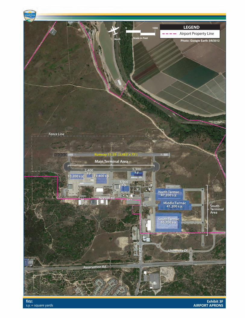
were removed from the current conventional hangar capacity, then there would be 41,300 square feet and 18 units available in conventional hangars. When considering the total estimated number of aircraft parking spaces in conventional hangars, there are enough to meet demand through the long-term planning period. When removing the three individually owned/leased conventional from the calculation, there is a long-term need for six more aircraft storage spaces in conventional hangars. Hangar Area Utilizing industry standard calculations for hangar area, there is a long-term need for an additional 3,500 square feet of T-hangar space. Approximately 14,800 square feet of box hangar space is projected to be needed through the long-term planning period. Up to 40,000 square feet of additional conventional hangar space may be needed depending on how these hangars are utilized in the future. Hangar Need Summary Hangar requirements are general in nature and are based on standard hangar size esti-mates. If a private developer desires to construct or lease a large hangar to house one plane, any extra space in that hangar may not be available for other aircraft. The actual hangar area needs will be dependent on the usage within each hangar. AIRCRAFT PARKING APRON The aircraft parking aprons should provide space for the number of locally based aircraft that are not stored in hangars, transient aircraft, maintenance activity, and circulation. Typically, a main apron is centrally located near the airside entry point, such as the termi-nal building or an FBO facility. Ideally, the main apron is large enough to accommodate transient airport users as well as a portion of locally based aircraft. Often, smaller aprons are available adjacent to FBO hangars and at other locations around an airport. The apron layout at Marina Municipal Airport follows this typical pattern. Being a former military airfield, there are large apron areas at the Airport. Exhibit 3F gen-erally shows apron areas and their size in square yards. In the main terminal area there are approximately 43,200 square yards of aircraft parking apron. The south terminal area encompasses approximately 154,100 square yards of pavement. Industry design standards suggest a methodology by which transient apron requirements can be determined from knowledge of busy-day operations. At Marina Municipal Airport, the number of itinerant spaces required is estimated at 13 percent of the busy-day itiner-ant operations (98 x 0.13 = 13). This results in a current need for 13 itinerant aircraft

AIRPORT MASTER PLAN – Marina Municipal Airport
FACILITY REQUIREMENTS 3-26 DRAFT FINAL – SEPTEMBER 2015
parking spaces. Of these, 10 (approximately 80 percent) should be for small aircraft and three should be for turboprops and business jets. By the long-term planning period, 19 spaces are estimated to be needed, with 15 identified for small aircraft and three for larger planes. A planning criterion of 800 square yards per aircraft was applied to determine future tran-sient apron area requirements for single and multi-engine aircraft. For turboprops and business jets (which can be much larger), a planning criterion of 1,600 square yards per aircraft position was used. The current need for transient apron area is estimated at 12,200 square yards. By the long-term planning period, approximately 17,400 square yards are estimated. For local tie-down needs, an additional ten spaces are identified for maintenance activity. Maintenance activity would include the movement of aircraft into and out of hangar facili-ties and temporary storage of aircraft on the ramp. Calculations indicated that local aircraft tie-down positions are adequate through the long term planning period. Total apron park-ing requirements are presented in Table 3J. TABLE 3J Aircraft Apron Requirements
Marina Municipal Airport
FORECAST
Currently Available
Calculated Need Short Term
Intermediate Term Long Term
Local Apron Positions 170 13 13 13 14 Local Apron Area (s.y.) 23,800 10,200 10,200 10,400 10,800 Transient Apron Positions 50 13 14 15 19 Piston Transient Positions 40 10 11 12 15 Turbine Transient Positions 10 3 3 3 4 Transient Apron Area (s.y.) 19,400 12,200 13,300 14,600 17,400 Total Apron Area (s.y) 43,200 22,400 23,500 25,000 28,200 Source: Coffman Associates analysis TERMINAL BUILDING FACILITIES General aviation terminal facilities have several functions. Space is necessary for a pilots’ lounge, flight planning, concessions, management, and storage. More advanced airports will have leasable space in the terminal building for features such as a restaurant, FBO line services, public meeting facilities, and other needs. This space is not necessarily limited to a single, separate terminal building, but can be included in space offered by FBOs. The methodology used in estimating general aviation terminal facility needs is based on the number of airport users forecast during the design hour. General aviation space require-ments were then based upon providing 120 square feet per design hour itinerant passen-ger. Design hour itinerant passengers are determined by multiplying design hour itinerant
Main Terminal Area
Fence Line
10,200 s.y.
2,400 s.y.
19,400 s.y.
5,900 s.y.
5,300 s.y.
North Tarmac47,200 s.y.
SouthTerminalArea
Middle Tarmac41,200 s.y.
South Tarmac65,700 s.y.
Airport Property Line
Runway 11-29 (3,483’ x 75’)
Reservation Rd.
University Dr.
Neeson Rd.
Imjin
Rd.
0 1000
Scale in FeetPhoto: Google Earth 5/6/2012
North
LEGEND
Exhibit 3FAIRPORT APRONS
Key:s.y. = square yards
AIRPORT MASTER PLAN – Marina Municipal Airport
FACILITY REQUIREMENTS 3-27 DRAFT FINAL – SEPTEMBER 2015
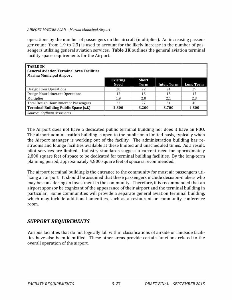
operations by the number of passengers on the aircraft (multiplier). An increasing passen-ger count (from 1.9 to 2.3) is used to account for the likely increase in the number of pas-sengers utilizing general aviation services. Table 3K outlines the general aviation terminal facility space requirements for the Airport. TABLE 3K General Aviation Terminal Area Facilities
Marina Municipal Airport
Existing
Need Short Term Inter. Term Long Term
Design Hour Operations 20 22 24 29 Design Hour Itinerant Operations 12 13 15 17 Multiplier 1.9 2.0 2.1 2.3 Total Design Hour Itinerant Passengers 23 27 31 40 Terminal Building Public Space (s.f.) 2,800 3,200 3,700 4,800 Source: Coffman Associates The Airport does not have a dedicated public terminal building nor does it have an FBO. The airport administration building is open to the public on a limited basis, typically when the Airport manager is working out of the facility. The administration building has re-strooms and lounge facilities available at these limited and unscheduled times. As a result, pilot services are limited. Industry standards suggest a current need for approximately 2,800 square feet of space to be dedicated for terminal building facilities. By the long-term planning period, approximately 4,800 square feet of space is recommended. The airport terminal building is the entrance to the community for most air passengers uti-lizing an airport. It should be assumed that these passengers include decision-makers who may be considering an investment in the community. Therefore, it is recommended that an airport sponsor be cognizant of the appearance of their airport and the terminal building in particular. Some communities will provide a separate general aviation terminal building, which may include additional amenities, such as a restaurant or community conference room. SUPPORT REQUIREMENTS Various facilities that do not logically fall within classifications of airside or landside facili-ties have also been identified. These other areas provide certain functions related to the overall operation of the airport.

AIRPORT MASTER PLAN – Marina Municipal Airport
FACILITY REQUIREMENTS 3-28 DRAFT FINAL – SEPTEMBER 2015
AUTOMOBILE PARKING Planning for adequate automobile parking is a necessary element for any airport. Parking needs can effectively be divided between transient airport users, locally based users, and airport business needs. Transient users include those employed at the airport and visitors, while locally based users primarily include those attending to their based aircraft. A plan-ning standard of 1.9 times the design hour passenger count provides the minimum number of vehicle spaces needed for transient users. Locally based parking spaces are calculated as one-half the number of based aircraft. A planning standard of 315 square feet per vehicle parking space, which includes area needed for circulation and handicap clearances, is utilized to determine total vehicle park-ing area needs. Parking requirements for the Airport are summarized in Table 3L. TABLE 3L Vehicle Parking Requirements
Marina Municipal Airport
Existing Short Term
Intermediate Term Long Term
Design Hour Itinerant Passengers 23 27 31 40 VEHICLE PARKING SPACES Itinerant Spaces 96 51 58 76 Based Spaces 17 28 30 35 Airport Business/Other 424 Individual Business Decision Total Parking Spaces 537 78 88 111 VEHICLE PARKING AREA Itinerant Parking Area (s.f.) 22,500 16,000 18,000 24,000 Based Parking Area (s.f.) 4,600 9,000 9,000 11,000 Airport Business/Other Parking Area (s.f.) 125,800 Individual Business Decision Total Parking Area (s.f.) 152,900 25,000 27,000 35,000 Source: Coffman Associates There appears to be enough designated vehicle parking through the long-term planning period. Parking should be made available in close proximity to the terminal building and airport businesses. In an effort to limit the level of vehicle traffic on the aircraft movement areas, many general aviation airports are providing separate parking in support of facilities with multiple aircraft parking positions, such as T-hangars. Vehicle parking spaces will be considered in conjunction with any additional facility needs in the alternatives chapter. AIRPORT ACCESS ROADS Imjin Road is the entrance road to the Airport, which provides access to the terminal area and the businesses. The Airport entrance road is adequate and it provides access to all ex-

AIRPORT MASTER PLAN – Marina Municipal Airport
FACILITY REQUIREMENTS 3-29 DRAFT FINAL – SEPTEMBER 2015
isting airport facilities. If any new facilities are located in undeveloped areas then new roads would be necessary. Current plans for the business park include additional roads which would provide access to the east side of the north, middle, and south aprons (see Exhibit 1K). The planned business park road system will provide access to additional aviation parcels and it terminates at the north end of the airport business park boundary. The intent of terminating the road sys-tem in this location is to allow for the future possibility of extending this road to the north side of the runway to provide access to any future development. In the Alternatives chapter, the feasibility of extending the airport business park road to the north side of the Airport will be analyzed. Of primary consideration is conformance to airport design standards. For example, any new roads must remain clear of the RSA, ROFA, ROFZ, and RPZ and consider the long-term airport layout (e.g., runway extension). AIRCRAFT RESCUE AND FIREFIGHTING (ARFF) FACILITIES Only those airports that are certificated under Title 14 Code of Federal Regulations (CFR), Part 139, are required to have on-site firefighting capabilities. The Airport is not a Part 139 airport and, therefore, is not required to have on-site firefighting capabilities. Instead, the local fire department responds to Airport emergencies. Some aircraft operators are permitted to use only airports with an on-field ARFF presence. This is common with fractional share, corporate, and some military/government operators. When this is the case, arrangements are made with the City fire department to be at the Airport during these operations. Currently, an agreement is in place between CIRPAS and the Airport to provide on-field ARFF capability when specific operations are planned, typi-cally visits from high ranking Navy personnel. FUEL STORAGE The Airport maintains two static fuel storage tanks on the main terminal area apron. Both tanks have a 12,000-gallon capacity. One is used for Jet A fuel and the other is for 100 low-lead fuel (AvGas). Additional fuel storage capacity should be planned when the Airport is unable to maintain an adequate supply and reserve. While each airport (or FBO) determines their own desired reserve, a 14-day reserve is common for general aviation airports. When additional capaci-ty is needed, it should be planned in 10,000- to 12,000-gallon increments in order to ac-commodate a full fuel tanker truck delivery.
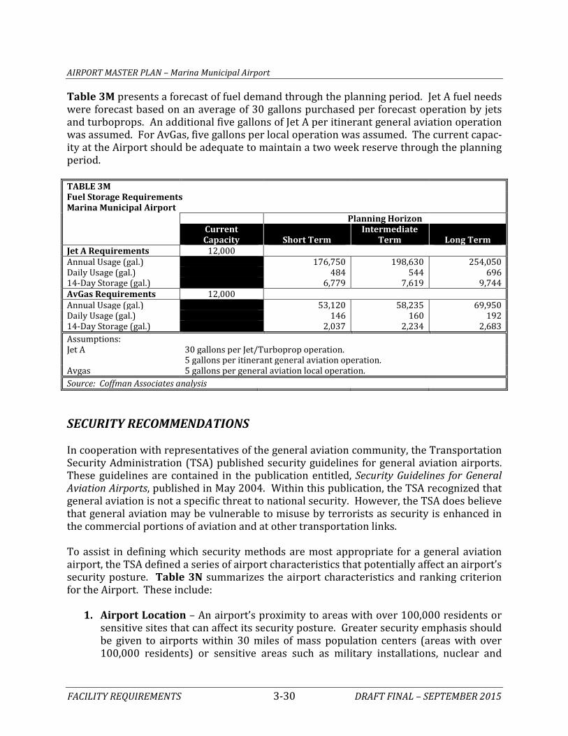
AIRPORT MASTER PLAN – Marina Municipal Airport
FACILITY REQUIREMENTS 3-30 DRAFT FINAL – SEPTEMBER 2015
Table 3M presents a forecast of fuel demand through the planning period. Jet A fuel needs were forecast based on an average of 30 gallons purchased per forecast operation by jets and turboprops. An additional five gallons of Jet A per itinerant general aviation operation was assumed. For AvGas, five gallons per local operation was assumed. The current capac-ity at the Airport should be adequate to maintain a two week reserve through the planning period. TABLE 3M Fuel Storage Requirements
Marina Municipal Airport Planning Horizon
Current Capacity Short Term
Intermediate Term Long Term
Jet A Requirements 12,000 Annual Usage (gal.) 176,750 198,630 254,050 Daily Usage (gal.) 484 544 696 14-Day Storage (gal.) 6,779 7,619 9,744 AvGas Requirements 12,000 Annual Usage (gal.) 53,120 58,235 69,950 Daily Usage (gal.) 146 160 192 14-Day Storage (gal.) 2,037 2,234 2,683 Assumptions:
Jet A 30 gallons per Jet/Turboprop operation. 5 gallons per itinerant general aviation operation. Avgas 5 gallons per general aviation local operation. Source: Coffman Associates analysis SECURITY RECOMMENDATIONS In cooperation with representatives of the general aviation community, the Transportation Security Administration (TSA) published security guidelines for general aviation airports. These guidelines are contained in the publication entitled, Security Guidelines for General Aviation Airports, published in May 2004. Within this publication, the TSA recognized that general aviation is not a specific threat to national security. However, the TSA does believe that general aviation may be vulnerable to misuse by terrorists as security is enhanced in the commercial portions of aviation and at other transportation links. To assist in defining which security methods are most appropriate for a general aviation airport, the TSA defined a series of airport characteristics that potentially affect an airport’s security posture. Table 3N summarizes the airport characteristics and ranking criterion for the Airport. These include:
1. Airport Location – An airport’s proximity to areas with over 100,000 residents or sensitive sites that can affect its security posture. Greater security emphasis should be given to airports within 30 miles of mass population centers (areas with over 100,000 residents) or sensitive areas such as military installations, nuclear and

AIRPORT MASTER PLAN – Marina Municipal Airport
FACILITY REQUIREMENTS 3-31 DRAFT FINAL – SEPTEMBER 2015
chemical plants, centers of government, national monuments, and/or international ports.
2. Based Aircraft – A smaller number of based aircraft increases the likelihood that il-
legal activities will be identified more quickly. Airports with based aircraft weighing more than 12,500 pounds warrant greater security measures.
3. Runways – Airports with longer paved runways are able to serve larger aircraft. Shorter runways are less attractive as they cannot accommodate the larger aircraft which have more potential for damage.
4. Operations – The number and type of operations should be considered in the secu-
rity assessment. TABLE 3N General Aviation Airport Security Measurement Tool Transportation Security Administration Assessment Scale
Security Characteristic Public Use
Airport Marina Municipal
Airport Location Within 20nm of mass population areas¹ 5 5 Within 30nm of a sensitive site² 4 4 Falls within outer perimeter of Class B airspace 3 0 Falls within boundaries of restricted airspace 3 0 Based Aircraft Greater than 101 based aircraft 3 0 26-100 based aircraft 2 2 11-25 based aircraft 1 0 10 or fewer based aircraft 0 0 Based aircraft over 12,500 pounds 3 0 Runways Runway length greater than 5,001 feet 5 0 Runways less than 5,000 feet and greater than 2,001 feet 4 4 Runway length less than 2,000 feet 2 0 Asphalt or concrete runway 1 1 Operations Over 50,000 annual operations 4 0 Part 135 operations (Air taxi and fractionals) 3 0 Part 137 operations (Agricultural aircraft) 3 0 Part 125 operations (20 or more passenger seats) 3 0 Flight training 3 0 Flight training in aircraft over 12,500 pounds 4 0 Rental aircraft 4 0 Maintenance, repair, and overhaul facilities conducting long-term storage of aircraft over 12,500 pounds 4 0
Totals 64 16 ¹ An area with a population over 100,000
² Sensitive sites include military installations, nuclear and chemical plants, centers of government, national monuments, and/or international ports Source: Security Guidelines for General Aviation Airports (TSA 2004)
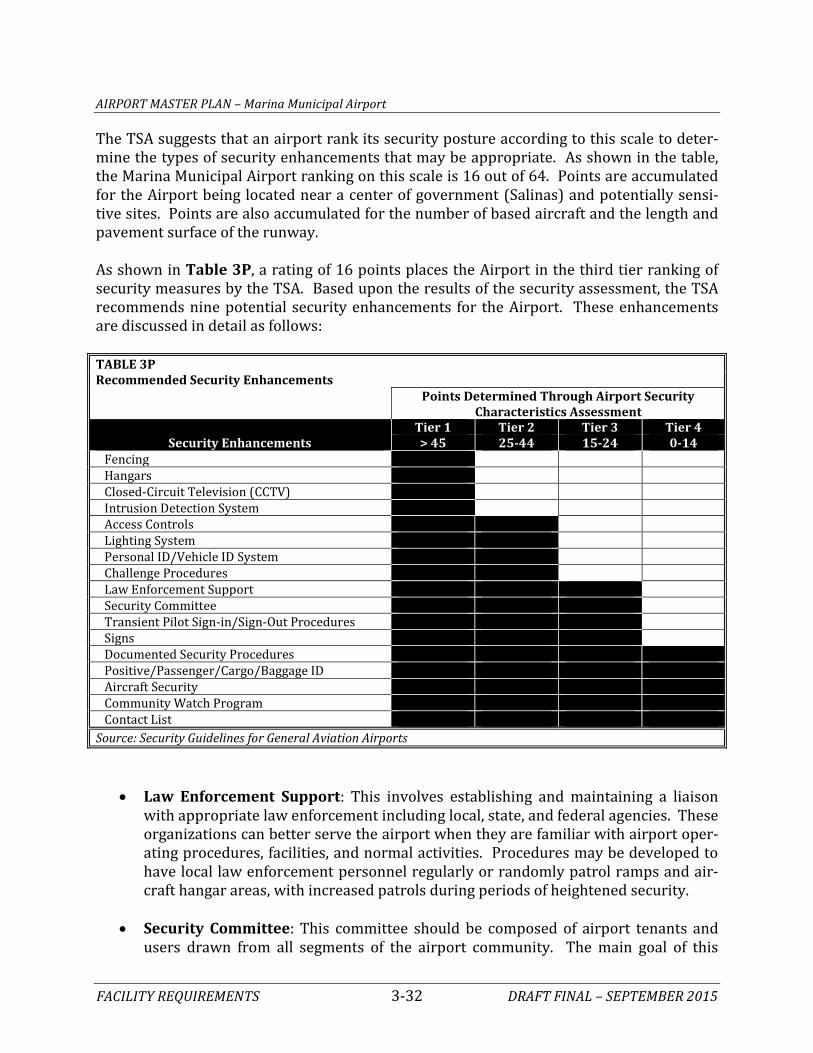
AIRPORT MASTER PLAN – Marina Municipal Airport
FACILITY REQUIREMENTS 3-32 DRAFT FINAL – SEPTEMBER 2015
The TSA suggests that an airport rank its security posture according to this scale to deter-mine the types of security enhancements that may be appropriate. As shown in the table, the Marina Municipal Airport ranking on this scale is 16 out of 64. Points are accumulated for the Airport being located near a center of government (Salinas) and potentially sensi-tive sites. Points are also accumulated for the number of based aircraft and the length and pavement surface of the runway. As shown in Table 3P, a rating of 16 points places the Airport in the third tier ranking of security measures by the TSA. Based upon the results of the security assessment, the TSA recommends nine potential security enhancements for the Airport. These enhancements are discussed in detail as follows: TABLE 3P Recommended Security Enhancements
Points Determined Through Airport Security
Characteristics Assessment
Security Enhancements Tier 1 Tier 2 Tier 3 Tier 4 > 45 25-44 15-24 0-14
Fencing Hangars Closed-Circuit Television (CCTV) Intrusion Detection System Access Controls Lighting System Personal ID/Vehicle ID System Challenge Procedures Law Enforcement Support Security Committee Transient Pilot Sign-in/Sign-Out Procedures Signs Documented Security Procedures Positive/Passenger/Cargo/Baggage ID Aircraft Security Community Watch Program Contact List Source: Security Guidelines for General Aviation Airports
• Law Enforcement Support: This involves establishing and maintaining a liaison with appropriate law enforcement including local, state, and federal agencies. These organizations can better serve the airport when they are familiar with airport oper-ating procedures, facilities, and normal activities. Procedures may be developed to have local law enforcement personnel regularly or randomly patrol ramps and air-craft hangar areas, with increased patrols during periods of heightened security.
• Security Committee: This committee should be composed of airport tenants and
users drawn from all segments of the airport community. The main goal of this

AIRPORT MASTER PLAN – Marina Municipal Airport
FACILITY REQUIREMENTS 3-33 DRAFT FINAL – SEPTEMBER 2015
group is to involve airport stakeholders in developing effective and reasonable se-curity measures and disseminating timely security information.
• Transient Pilot Sign-in/Sign-Out Procedures: This involves establishing proce-
dures to identify non-based pilots and aircraft using their facilities, and implement-ing sign-in/sign-out procedures for all transient operators and associating them with their parked aircraft. Having assigned spots for transient parking areas can help to easily identify transient aircraft on an apron.
• Signs: The use of signs provides a deterrent by warning of facility boundaries as
well as notifying of the consequences for violation.
• Documented Security Procedures: This refers to having a written security plan. This plan would include documenting the security initiatives already in place at the Airport, as well as any new enhancements. This document should consist of airport and local law enforcement contact information, and include utilization of a program to increase airport user awareness of security precautions such as an airport watch program.
• Positive/Passenger/Cargo/Baggage ID: A key point to remember regarding gen-
eral aviation passengers is that the persons boarding these flights are generally bet-ter known to airport personnel and aircraft operators than the typical passenger on a commercial airliner. Recreational general aviation passengers are typically friends, family, or acquaintances of the pilot in command. Charter/ sightseeing pas-sengers typically will meet with the pilot or other flight department personnel well in advance of any flights. Suspicious activities, such as use of cash for flights or probing or inappropriate questions, are more likely to be quickly noted and authori-ties could be alerted. For corporate operations, typically all parties onboard the air-craft are known to the pilots. Airport operators should develop methods by which individuals visiting the airport can be escorted into and out of aircraft movement and parking areas.
• Aircraft Security: The main goal of this security enhancement is to prevent the in-
tentional misuse of general aviation aircraft for criminal purposes. Proper securing of aircraft is the most basic method of enhancing general aviation airport security. Pilots should employ multiple methods of securing their aircraft to make it as diffi-cult as possible for an unauthorized person to gain access to it. Some basic methods of securing a general aviation aircraft include: ensuring that door locks are consist-ently used to prevent unauthorized access or tampering with the aircraft; using keyed ignitions where appropriate; storing the aircraft in a hangar, if available; and locking hangar doors, using an auxiliary lock to further protect aircraft from unau-thorized use (i.e., propeller, throttle, and/or tie-down locks); and ensuring that air-craft ignition keys are not stored inside the aircraft.

AIRPORT MASTER PLAN – Marina Municipal Airport
FACILITY REQUIREMENTS 3-34 DRAFT FINAL – SEPTEMBER 2015
• Community Watch Program: The vigilance of airport users is one of the most prevalent methods of enhancing security at general aviation airports. Typically, the user population is familiar with those individuals who have a valid purpose for be-ing on the airport property. Consequently, new faces are quickly noticed. A watch program should include elements similar to those listed below. These recommenda-tions are not all-inclusive. Additional measures that are specific to each airport should be added as appropriate, including:
- Coordinate the program with all appropriate stakeholders, including airport offi-
cials, pilots, businesses, and/or other airport users. - Hold periodic meetings with the airport community. - Develop and circulate reporting procedures to all who have a regular presence
on the airport. Encourage proactive participation in aircraft and facility security and heightened awareness measures. This should include encouraging airport and line staff to “query” unknowns on ramps, near aircraft, etc.
- Post signs promoting the program, warning that the airport is watched. Include
appropriate emergency phone numbers on the sign. - Install a bulletin board for posting security information and meeting notices. - Provide training to all involved for recognizing suspicious activity and appropri-
ate response tactics.
• Contact List: This involves the development of a comprehensive list of responsible personnel/agencies to be contacted in the event of an emergency procedure. The list should be distributed to all appropriate individuals. Additionally, in the event of a security incident, it is essential that first responders and airport management have the capability to communicate. Where possible, coordinate radio communication and establish common frequencies and procedures to establish a radio communica-tions network with local law enforcement.
FRACTIONAL JET OPERATOR SECURITY REQUIREMENTS The major fractional jet operators have established minimum standards for airports serv-ing their aircraft. These minimum standard documents specify the following general secu-rity requirements: Identification: The Airport should issue unique identification badges for employees who have access to the aircraft operations areas. Unescorted passenger access to the ramp is prohibited.
AIRPORT MASTER PLAN – Marina Municipal Airport
FACILITY REQUIREMENTS 3-35 DRAFT FINAL – SEPTEMBER 2015
Employees: The Airport must conduct FAA-compliant background checks on each employ-ee. The Airport must have pre-employment drug screening. Aircraft Security: Aircraft cannot be left unattended when the ground power unit or auxil-iary power unit is operating. Aircraft must be locked when unattended. Aircraft must be parked in well-lit, highly visible areas with a minimum of six-foot chain link fencing. Secu-rity cameras are preferred. Sightseers or visitors are not allowed access aboard or near air-craft. Facility Security: Visual surveillance of all aircraft operational areas belonging to the Air-port is required. The Airport shall establish controlled access to the aircraft operational areas. The Airport should maintain at least six feet between the safety fence and parked ground equipment. Bushes and shrubs must be less than four feet in height. SECURITY SUMMARY Other security measures may be considered by the Airport as the local need demands and may include full perimeter fencing, hangar availability, closed-circuit television, and intru-sion detection systems to name a few. The security guidelines outlined here are only recommendations and are not regulatory in nature for general aviation airports. As such, there is no specific federal funding eligibility associated with the ranking for the Airport. ADDITIONAL CONSIDERATIONS During the master planning process, it is necessary to address additional local issues that may have an impact on the Airport. Three such issues are: the potential for air cargo activi-ty, skydiving activity, and use of airport property for non-aviation purposes. AIR CARGO POTENTIAL Air cargo is comprised of air freight and air mail. The air cargo industry includes all-cargo commercial carriers, passenger airlines, freight forwarders and customs brokers, and air freight truckers. Air freight is handled by both passenger airlines (belly freight) and all-cargo airlines. Air mail is now handled primarily by a contract carrier (currently FedEx through 2020) for the United States Postal Service, as air mail on passenger airlines is re-stricted to packages of 16 ounces or less. Security restrictions since 9/11 have affected all freight carried in the bellies of passenger airlines. The mail restriction, in addition to the “known shipper” requirements for carrying

AIRPORT MASTER PLAN – Marina Municipal Airport
FACILITY REQUIREMENTS 3-36 DRAFT FINAL – SEPTEMBER 2015
cargo on passenger airlines, has given the all-cargo airlines a competitive advantage, at least in the short term. How future long term requirements develop could affect the indus-try. Many airlines rely on cargo to generate incremental revenue. As restrictions on air freight are refined over time, airlines are likely to become competitive in air freight again. The air cargo industry was deregulated in 1977, one year before passenger airline deregu-lation. Since deregulation, the composition of the carrier group providing cargo services has changed dramatically. Most notable is the emergence of the integrated all-cargo air-lines such as FedEx and UPS. Integrated air carriers are so named because they integrate the functions of traditional all-cargo airlines (airport-to-airport service) and freight for-warders (pickup and delivery services). During the 1990s, the air-cargo industry experienced unprecedented consolidation. Well-known cargo carriers such as Airborne Express, DHL, and Emery Worldwide, as well as several others were acquired by other air cargo carriers. The all-cargo carriers have devel-oped a “hub and spoke” system similar to the passenger airlines. FedEx utilizes the Mem-phis International Airport as its main hub, while UPS utilizes Louisville International Air-port for their main hub. Both of these all cargo carriers have presence at most major air-ports in the country. Freight forwarders are the intermediary between the shippers and cargo carriers, whether it is air, ground, rail, or water. They are an important part of the cargo system as they have the ability to organize cargo transportation efficiently and cost-effectively. The forwarder has the capability to pool shipments to effectively make use of the capacity available. Obviously, belly freight is only handled at airports with passenger service. Airports with commuter or charter-only service generally have only minor belly freight volumes. The in-tegrated carriers typically choose airports based upon what serves their system best. A re-gional or national sort facility is going to consider locations with regard to the market it serves, as well as the presence of a sufficient work force. Today, Oakland International Air-port serves this function as FedEx and UPS operate at the airport. For the past ten years, the integrated air cargo carriers have matured. FedEx and UPS have established a business model where air cargo is delivered to a central hub and trucks dis-tribute cargo over great distances. It has proven economical to utilize trucking over several hundred miles rather than utilize smaller air cargo aircraft to smaller airports. Even during 2008 when fuel and oil prices spiked, there was very little interest by the integrated air cargo operators to expand the air portion of the delivery mechanism. The primary air cargo operators in the region currently utilize Monterey Regional Airport. Both FedEx and UPS subcontract to local air cargo carriers who fly daily deliveries to larger sort facilities in the San Francisco Bay area. Both of these contractors utilize Cessna Cara-van turboprop aircraft. Transfer of this activity to Marina Municipal Airport is considered remote at this time for two primary reasons:
AIRPORT MASTER PLAN – Marina Municipal Airport
FACILITY REQUIREMENTS 3-37 DRAFT FINAL – SEPTEMBER 2015
• Air cargo is time-sensitive as delivery dates for many packages are guaranteed. As a result, it is mission critical that the air cargo carriers be capable of arriving and de-parting in even very poor weather conditions. The instrument approach capability at Monterey Regional Airport permits operations in poor conditions.
• The air cargo operators desire to have various services and amenities available at an airport. This might include terminal services, such as 24-hour pilots’ lounge, flight planning facilities, restaurants, etc. These facilities are available at Monterey Re-gional Airport, but not at Marina Municipal Airport.
SKYDIVING ACTIVITY Marina Municipal Airport supports a significant level of skydiving activity. In fact, aeronau-tical sectional charts indicate this with a small parachute symbol alerting pilots to possible skydiving activity. In these locations, parachutists are free to utilize the airport without additional notification and pilots should be aware of their potential presence. The FAA regulates skydiving activities under Part 105 Parachute Operations of Title 14 of the Code of Federal Regulations, Part 105 (14 CFR 105). Flight operations for skydiving are conducted under Part 91 General Operating and Flight Rules (14 CFR 91). FAA AC 105-2D, Sport Parachuting and AC 90-66A, Recommended Standard Traffic Patterns for Aeronautical Operations at Airports without Operating Control Towers provide additional guidance about aspects of sky diving operations. The FAA’s Airports Compliance Manual (Order 5190.6B) details an airport’s obligation with respect to skydiving and other activities. In addition, the use permit for Skydive Monterey Bay includes adherence to:
• United States Parachute Association (USPA) Basic Safety Requirements; • USPA Skydiver’s Information Manual; • USPA Skydiving Aircraft Operations Manual; • Federal Aviation Regulations (FAR) Part 61 – Certification: Pilots, Flight Instructors,
and Ground Instructors; • FAR Part 65 – Certification: Airmen other than Flight Crewmembers; • FAR Part 119 – Certification: Air Carriers and Commercial Operators; • AC 91-45C – Waivers: Aviation Events – Chapter 6: Waiver Provisions; • 49 CFR Part 830, National Transportation Safety Board, Notification and Reporting of
Aircraft Accidents or Incidents and Overdue Aircraft, and Preservation of Aircraft Wreckage, Mail, Cargo, and Records;
• Letter of Agreement with FAA control tower staff; and • City of Marina Ordinance No. 96-01, “Operating Ordinance for Marina Municipal
Airport.” According to the Airports Compliance Manual, parachute jumping is an aeronautical activity and requests to use an airport for this purpose or to establish a drop zone within the air-

AIRPORT MASTER PLAN – Marina Municipal Airport
FACILITY REQUIREMENTS 3-38 DRAFT FINAL – SEPTEMBER 2015
port boundaries must be evaluated by the airport operators on the same basis as any other aeronautical activity. Airports that accept federal grants, such as Marina Municipal Airport, cannot discriminate against any business conducting aeronautical activities, but reasonable limitations may be implemented to ensure safe operation of the airport including:
• Time Periods for skydiving. • Fees and charges. • Requirements for general liability insurance.
At Marina Municipal Airport, the skydiving operator has agreed to pay a reasonable charge that is not unjustly discriminatory and to comply with all other terms and conditions of a Conditional Airport Use Permit for the Use of the Interim Parachute Drop Zone issued by the City Council Resolution No. 2012-73. The skydiving operator, as a condition of the Conditional Airport Use Permit, provides airport liability insurance that names the Airport owner as an additional insured. As a condition of the Conditional Airport Use Permit the skydiving operator is required to ensure each jumper executes a Release of Liability and Assumption of Risk Agreement. To further quote from the Airports Compliance Manual, “the airport owner is not required to permit this activity if, in his judgment, it creates a safety hazard to the normal operations of aircraft arriving or departing from the airport, nor is the airport owner required to close the airport to provide a safe environment for parachute jumpers.” The FAA Flight Stand-ards and Air Traffic division has the authority to make a final determination of the reason-ableness of any airport owner’s restrictions. Drop Zones A drop zone is a designated landing area clear of obstacles. Drop zone operators are re-quired to contact the FAA Flight Service Station for the latest weather forecast and winds aloft forecast. For intermittent skydiving, the operator files a Notice to Airmen (NOTAM), at least one hour prior to the jump, to alert area pilots of the skydiving activity. For contin-uous skydiving activity, operators may file a permanent NOTAM which are often depicted on aeronautical charts with a parachute symbol. The aeronautical chart covering Marina Municipal Airport includes the parachute symbol. The primary responsibility of the FAA related to skydiving is the protection of air traffic and persons and property on the ground. The FAA considers the Basic Safety Require-ments (BSR) described in the Skydiver’s Information Manual as published by the United States Parachute Association to be industry best practices. The guidelines are widely ac-cepted for use by the industry, parachute centers, and individuals. According to FAA AC 105-2D, Sport Parachuting, airports may designate suitable parachute landing areas; however, at times there may be inadvertent landings in other areas includ-ing on runways, taxiways, clearways, and obstacle-free zones. While landings in these are-

AIRPORT MASTER PLAN – Marina Municipal Airport
FACILITY REQUIREMENTS 3-39 DRAFT FINAL – SEPTEMBER 2015
as are not prohibited, they should not be designated as a primary landing area and should be vacated as soon as practical. The Skydiver’s Information Manual, provides minimum drop zone requirements which are excerpted as follows:
1. Areas used for skydiving should be unobstructed, with the following minimum radi-al distances to the nearest hazard: a. Solo students and A-license holders – 100 meters (328 feet) b. B- and C-license holders and all tandem skydives – 50 meters (164 feet) c. D-license holders – 12 meters (39 feet)
2. Hazards are defined as telephone and power lines, towers, buildings, open bodies of
water, highways, automobiles, and clusters of trees covering more than 3,000 square meters.
3. Manned ground-to-air communications (e.g., radios, panels, smoke, lights) are to be present on the drop zone during skydiving operations.
Currently, the Airport has designated an interim drop zone which is located immediately adjacent to the east end of the north tarmac (see Exhibit 1C). This area is suitable as a drop zone; however, it is planned to be developed for aviation uses in the future as part of the airport business park. As a result other suitable locations will be identified as part of the Alternatives chapter. AIRPORT LAND USE OBLIGATIONS The Airport has accepted grants for capital improvements from the FAA. As such, the air-port sponsor has agreed to certain grant assurances (see Appendix B). Grant assurances related to land use assure that airport property will be reserved for aeronautical purposes. If the airport sponsor wishes to sell (release) airport land or lease airport land for a non-aeronautical purpose (land use change), they must the first secure FAA approval. The Air-port Layout Plan and the Airport Property Map must then be updated to reflect the sale or land use change of the identified property. When the duration of the physical useful life of a specific grant improvement ends, the sponsor is automatically released from its federal obligations for that grant without any formal action from the FAA. The physical useful life of such a facility extends to the time it is serviceable and useable with ordinary day-to-day maintenance. However, airport land acquired with federal assistance under the Airport Improvement Program (AIP) and/or conveyed as surplus or non-surplus property is federally obligated in perpetuity (forever). The Marina Municipal Airport property was conveyed as surplus property and is therefore federally obligated in perpetuity.
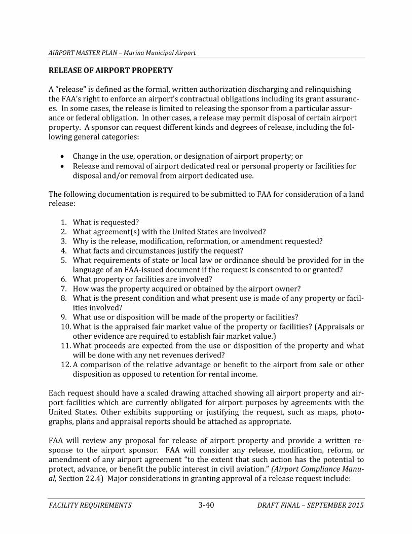
AIRPORT MASTER PLAN – Marina Municipal Airport
FACILITY REQUIREMENTS 3-40 DRAFT FINAL – SEPTEMBER 2015
RELEASE OF AIRPORT PROPERTY A “release” is defined as the formal, written authorization discharging and relinquishing the FAA’s right to enforce an airport’s contractual obligations including its grant assuranc-es. In some cases, the release is limited to releasing the sponsor from a particular assur-ance or federal obligation. In other cases, a release may permit disposal of certain airport property. A sponsor can request different kinds and degrees of release, including the fol-lowing general categories:
• Change in the use, operation, or designation of airport property; or • Release and removal of airport dedicated real or personal property or facilities for
disposal and/or removal from airport dedicated use. The following documentation is required to be submitted to FAA for consideration of a land release:
1. What is requested? 2. What agreement(s) with the United States are involved? 3. Why is the release, modification, reformation, or amendment requested? 4. What facts and circumstances justify the request? 5. What requirements of state or local law or ordinance should be provided for in the
language of an FAA-issued document if the request is consented to or granted? 6. What property or facilities are involved? 7. How was the property acquired or obtained by the airport owner? 8. What is the present condition and what present use is made of any property or facil-
ities involved? 9. What use or disposition will be made of the property or facilities? 10. What is the appraised fair market value of the property or facilities? (Appraisals or
other evidence are required to establish fair market value.) 11. What proceeds are expected from the use or disposition of the property and what
will be done with any net revenues derived? 12. A comparison of the relative advantage or benefit to the airport from sale or other
disposition as opposed to retention for rental income.
Each request should have a scaled drawing attached showing all airport property and air-port facilities which are currently obligated for airport purposes by agreements with the United States. Other exhibits supporting or justifying the request, such as maps, photo-graphs, plans and appraisal reports should be attached as appropriate. FAA will review any proposal for release of airport property and provide a written re-sponse to the airport sponsor. FAA will consider any release, modification, reform, or amendment of any airport agreement “to the extent that such action has the potential to protect, advance, or benefit the public interest in civil aviation.” (Airport Compliance Manu-al, Section 22.4) Major considerations in granting approval of a release request include:
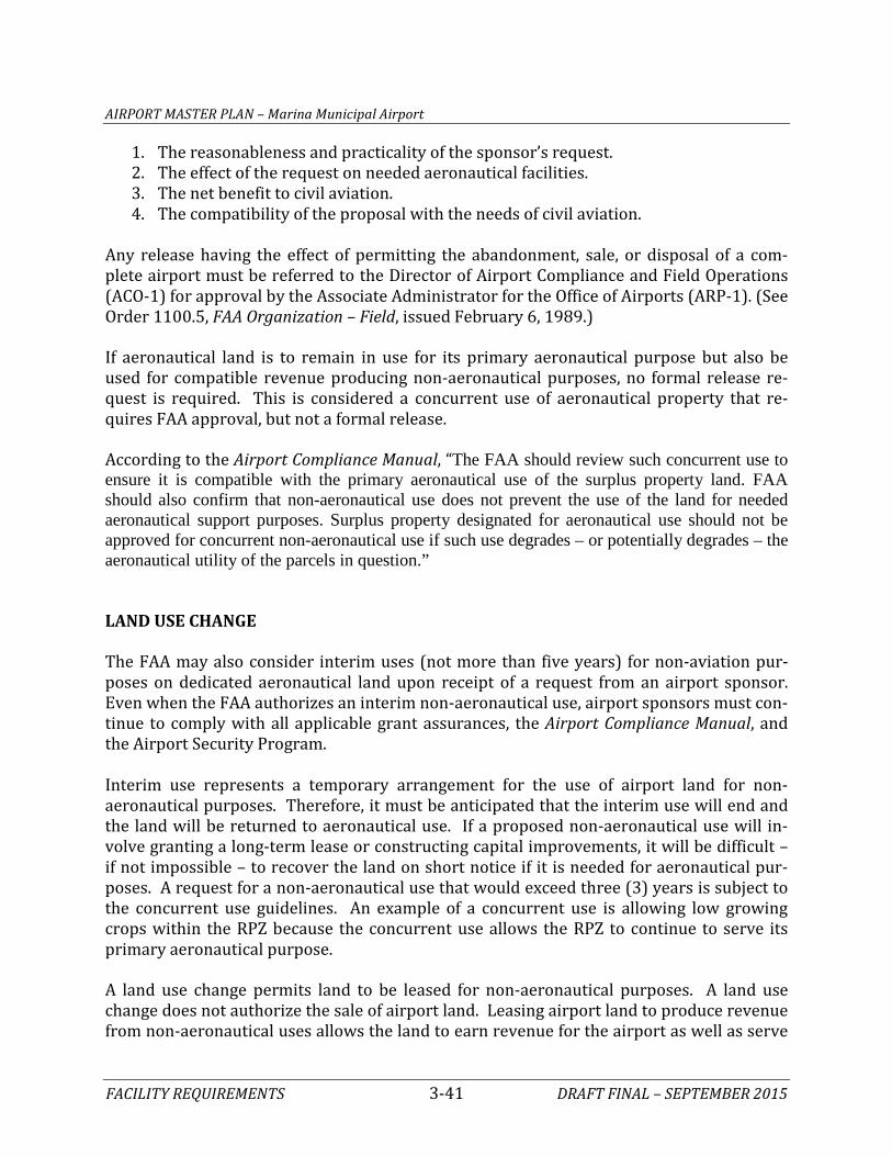
AIRPORT MASTER PLAN – Marina Municipal Airport
FACILITY REQUIREMENTS 3-41 DRAFT FINAL – SEPTEMBER 2015
1. The reasonableness and practicality of the sponsor’s request. 2. The effect of the request on needed aeronautical facilities. 3. The net benefit to civil aviation. 4. The compatibility of the proposal with the needs of civil aviation.
Any release having the effect of permitting the abandonment, sale, or disposal of a com-plete airport must be referred to the Director of Airport Compliance and Field Operations (ACO-1) for approval by the Associate Administrator for the Office of Airports (ARP-1). (See Order 1100.5, FAA Organization – Field, issued February 6, 1989.) If aeronautical land is to remain in use for its primary aeronautical purpose but also be used for compatible revenue producing non-aeronautical purposes, no formal release re-quest is required. This is considered a concurrent use of aeronautical property that re-quires FAA approval, but not a formal release. According to the Airport Compliance Manual, “The FAA should review such concurrent use to ensure it is compatible with the primary aeronautical use of the surplus property land. FAA should also confirm that non-aeronautical use does not prevent the use of the land for needed aeronautical support purposes. Surplus property designated for aeronautical use should not be approved for concurrent non-aeronautical use if such use degrades – or potentially degrades – the aeronautical utility of the parcels in question.” LAND USE CHANGE The FAA may also consider interim uses (not more than five years) for non-aviation pur-poses on dedicated aeronautical land upon receipt of a request from an airport sponsor. Even when the FAA authorizes an interim non-aeronautical use, airport sponsors must con-tinue to comply with all applicable grant assurances, the Airport Compliance Manual, and the Airport Security Program. Interim use represents a temporary arrangement for the use of airport land for non-aeronautical purposes. Therefore, it must be anticipated that the interim use will end and the land will be returned to aeronautical use. If a proposed non-aeronautical use will in-volve granting a long-term lease or constructing capital improvements, it will be difficult – if not impossible – to recover the land on short notice if it is needed for aeronautical pur-poses. A request for a non-aeronautical use that would exceed three (3) years is subject to the concurrent use guidelines. An example of a concurrent use is allowing low growing crops within the RPZ because the concurrent use allows the RPZ to continue to serve its primary aeronautical purpose. A land use change permits land to be leased for non-aeronautical purposes. A land use change does not authorize the sale of airport land. Leasing airport land to produce revenue from non-aeronautical uses allows the land to earn revenue for the airport as well as serve
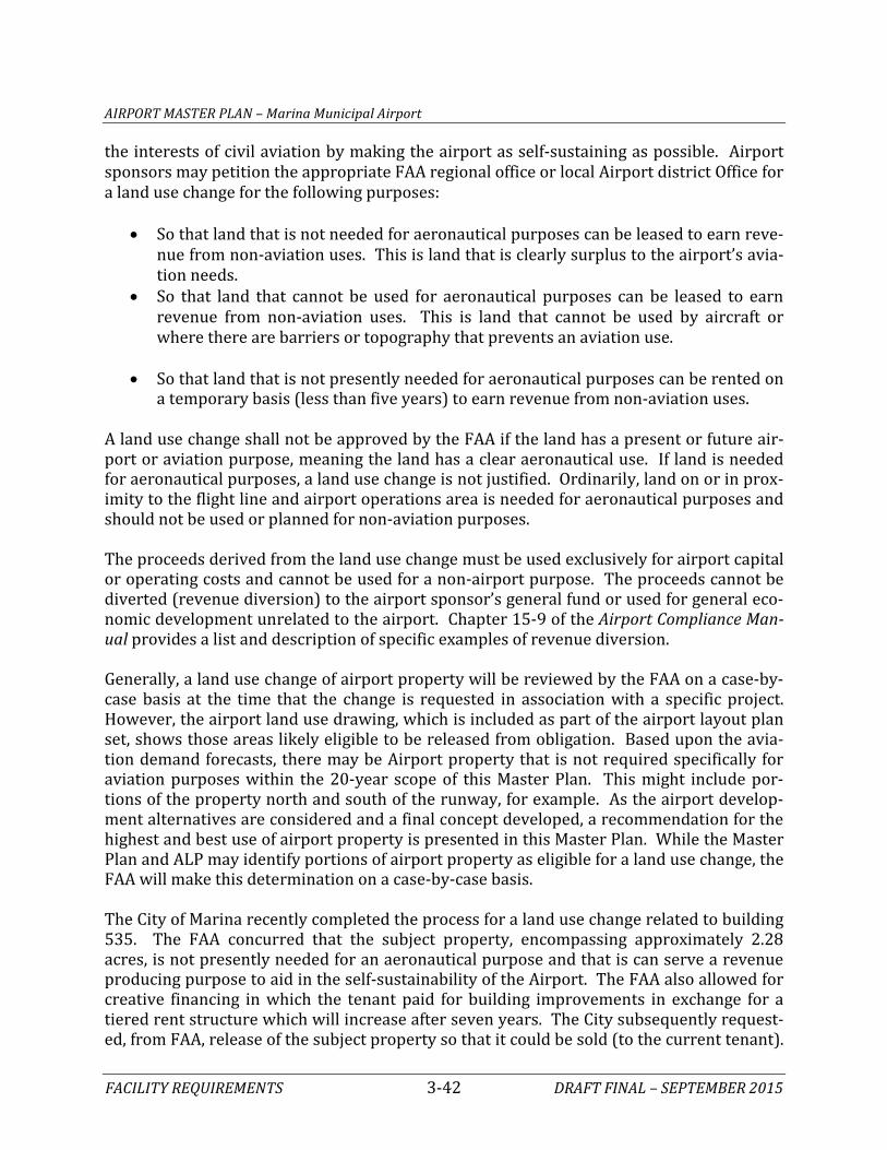
AIRPORT MASTER PLAN – Marina Municipal Airport
FACILITY REQUIREMENTS 3-42 DRAFT FINAL – SEPTEMBER 2015
the interests of civil aviation by making the airport as self-sustaining as possible. Airport sponsors may petition the appropriate FAA regional office or local Airport district Office for a land use change for the following purposes:
• So that land that is not needed for aeronautical purposes can be leased to earn reve-nue from non-aviation uses. This is land that is clearly surplus to the airport’s avia-tion needs.
• So that land that cannot be used for aeronautical purposes can be leased to earn revenue from non-aviation uses. This is land that cannot be used by aircraft or where there are barriers or topography that prevents an aviation use.
• So that land that is not presently needed for aeronautical purposes can be rented on
a temporary basis (less than five years) to earn revenue from non-aviation uses.
A land use change shall not be approved by the FAA if the land has a present or future air-port or aviation purpose, meaning the land has a clear aeronautical use. If land is needed for aeronautical purposes, a land use change is not justified. Ordinarily, land on or in prox-imity to the flight line and airport operations area is needed for aeronautical purposes and should not be used or planned for non-aviation purposes.
The proceeds derived from the land use change must be used exclusively for airport capital or operating costs and cannot be used for a non-airport purpose. The proceeds cannot be diverted (revenue diversion) to the airport sponsor’s general fund or used for general eco-nomic development unrelated to the airport. Chapter 15-9 of the Airport Compliance Man-ual provides a list and description of specific examples of revenue diversion. Generally, a land use change of airport property will be reviewed by the FAA on a case-by-case basis at the time that the change is requested in association with a specific project. However, the airport land use drawing, which is included as part of the airport layout plan set, shows those areas likely eligible to be released from obligation. Based upon the avia-tion demand forecasts, there may be Airport property that is not required specifically for aviation purposes within the 20-year scope of this Master Plan. This might include por-tions of the property north and south of the runway, for example. As the airport develop-ment alternatives are considered and a final concept developed, a recommendation for the highest and best use of airport property is presented in this Master Plan. While the Master Plan and ALP may identify portions of airport property as eligible for a land use change, the FAA will make this determination on a case-by-case basis. The City of Marina recently completed the process for a land use change related to building 535. The FAA concurred that the subject property, encompassing approximately 2.28 acres, is not presently needed for an aeronautical purpose and that is can serve a revenue producing purpose to aid in the self-sustainability of the Airport. The FAA also allowed for creative financing in which the tenant paid for building improvements in exchange for a tiered rent structure which will increase after seven years. The City subsequently request-ed, from FAA, release of the subject property so that it could be sold (to the current tenant).

AIRPORT MASTER PLAN – Marina Municipal Airport
FACILITY REQUIREMENTS 3-43 DRAFT FINAL – SEPTEMBER 2015
This request was denied because the property serves an Airport purpose and it benefits the Airport. The FAA did not identify any justification to release the property from federal ob-ligations. NONCOMPLIANT LAND USES The FAA Airport Compliance Manual offers several specific examples of noncompliant land uses which are excerpted below: Non-Aeronautical Leaseholds The most common improper and noncompliant land uses are situations where non-aeronautical leaseholds are located on designated aeronautical use land without FAA ap-proval or on property not released by FAA, and permitting dedicated aeronautical property to be used for non-aeronautical uses. Examples of typical uses include using hangars to store vehicles or other unrelated items. Other improper land uses found in the past have included using aeronautical land for non-aeronautical purposes such as animal control fa-cilities, non-airport vehicle and maintenance equipment storage, aircraft museums, and municipal administrative offices. (NOTE: Approval of an ALP showing future non-aeronautical land use does not constitute FAA approval for that non-aeronautical use when it may actually occur. The ALP is a planning document only. FAA approval will be required at the time the land is to be used for a non-aeronautical purpose.) Roads and Other Structures A public road built through airport property without FAA approval is a problem if it im-pacts an RSA, Part 77 surfaces, the RPZ, or an OFZ. SUMMARY The intent of this chapter has been to outline the facilities required to meet potential avia-tion demand projected for Marina Municipal Airport for the next 20 years. A summary of these needs is presented on Exhibit 3G. In an effort to provide a more flexible Master Plan, the yearly forecasts from Chapter Two have been converted to planning horizon levels. The short term roughly corresponds to a 5-year time frame, the intermediate term is ap-proximately 10 years, and the long term is 20 years. By utilizing planning horizons, airport management can focus on demand indicators for initiating projects and grant requests ra-ther than on specific dates in the future. Runway 11-29 currently falls within design category B-II (small aircraft). This category in-cludes most piston and turboprop general aviation aircraft. Specifically, the combination of

AIRPORT MASTER PLAN – Marina Municipal Airport
FACILITY REQUIREMENTS 3-44 DRAFT FINAL – SEPTEMBER 2015
the operations by the based King Air A90 (B-I) and the Twin Otter (A-II) justify this classifi-cation. Ultimately, the Airport is planned to accommodate C/D-II design standards. This classification includes most general aviation jets in the national fleet. The analysis presented in this chapter indicates an immediate need for the runway to be extended to a minimum length of 3,900 feet. According to FAA design guidelines this is the length necessary to accommodate operations by all small aircraft, including those with 10 or more passenger seats. Intermediate and long-term planning indicate the runway should be planned to 5,000 feet and then ultimately 5,800 feet in length. Specific documentation of 500 annual itinerant operations by aircraft needing the additional runway length will be necessary prior to extending the runway beyond 3,900 feet in length. On the landside, planning calculations indicate a long term need for additional aircraft hangar space. The Alternatives chapter will identify the appropriate type and location for future hangars. The Airport does not have an FBO or dedicated terminal building. There is an administra-tion building; however, it is only open to the public when City staff is working from this fa-cility, which is on a part-time basis currently. A suitable location for terminal functions will be considered in the Alternatives chapter. This chapter also introduced concepts related to various federal obligations to which the Airport has agreed by accepting both the Airport property as well as subsequent develop-ment grants. Of particular note are the limited allowances for non-aeronautical activities and the restrictions of airport property. The next chapter, Alternatives, will examine potential improvements to the airfield system and the landside. Most of the alternatives discussion will focus on those capital improve-ments that would be eligible for federal grant funds. Other projects of local concern will also be presented such as maintenance or security issues. On the landside, several facility layouts that meet the forecast demands over the next 20 years will be presented. Ultimate-ly, an overall airport layout that presents a vision beyond the 20-year scope of the Master Plan will be included.

Runway 11-29 Runway 11-29 Runway 11-29
Design Aircraft: B-I-1A Design Aircraft: B-II-2 Design Aircraft: C-II-3
RDC: B-I-5000 RDC: B-II-5000 RDC: C-II-2400
3,483' x 75' 3,900'/4,000’/5,000’ x 75' 5,000' or 5,800' x 100'
20-S; 50-D Maintain 30-S; 60-D
Standard RSA, OFA, OFZ, POFZ Maintain Maintain
RPZs under airport ownership Purchase and remove RPZ Purchase and remove RPZ incompatibilities as necessary incompatibilities as necessary
Non-precision markings Maintain Precision markings
MIRL Maintain HIRL
TDG: 1A TDG: 2 TDG: 3
Centerline marking Maintain Maintain
Taxiways are 50' wide Maintain Maintain
MITL Maintain Maintain
AWOS, 2 lighted windsocks, Relocate beacon Maintain wind-tee, segmented circle, beacon
Runway 11-29 Runway 11-29 Runway 11-29
1-mile NPI 1-mile NPI ½-mile Precision Approach
Runway 11-29 Runway 11-29 Runway 11-29
PAPI-2L (Rwy 29) Maintain Upgrade to PAPI-4L (11-29)
Approach Lighting System: None Maintain MALSR (29)
REIL: None Maintain REIL (Rwy 11)
Based Aircraft 50 55 60 70Aircraft to be Hangared Single Engine 41 41 43 49 Multi-Engine 0 1 1 2 Turboprop 3 4 4 5 Jet 1 2 3 4 Helicopter 0 0 1 1Other/Experimental 4 4 5 5Total to be Hangared 49 52 57 66
Hangar Positions T-Hangars Positions 24 19 20 22Box Hangar Positions 20 11 14 17Conventional Hangar Positions1 43/18 19 21 25
Hangar Area T-Hangars (s.f.) 23,500 22,000 24,000 27,000Executive Box Hangar (s.f.) 27,200 28,000 36,000 42,000Conventional Hangar1 (s.f.) 125,500/41,300 47,000 54,000 63,000Maintenance Area (s.f.) 25,500 9,600 10,500 12,300
Aircraft Parking Local Apron Positions 170 13 13 14Local Apron Area (s.y.) 23,800 10,200 10,400 10,800Transient Apron Positions 50 14 15 18 Piston Transient Positions 40 11 12 15 Turbine Transient Positions 10 3 3 4Transient Apron Area (s.y.) 19,400 13,300 14,600 17,400Total Apron Area (s.y) 43,200 23,500 25,000 28,200
Auto Parking Total Spaces 537 78 88 111Total Area (s.f.) 152,900 25,000 27,000 35,000Terminal Building Area (s.f.) 0 3,200 3,700 4,800
RUNWAYSRUNWAYSRUNWAYS
TAXIWAYSTAXIWAYSTAXIWAYS
RDC - Runway Design CodeRSA - Runway Safety AreaOFA - Object Free Area OFZ/POFZ - Obstacle Free Zone/Precision Obstacle Free Zone RPZ - Runway Protection ZoneTDG - Taxiway Design CodePAPI - Precision Approach Path IndicatorREIL - Runway End Identification Lights
MIRL/HIRL - Medium/High Intensity Runway Lighting MITL - Medium Intensity Taxiway LightingAWOS - Automated Weather Observation SystemMALSR - Medium Intensity Approach Lighting System with Runway Alignment Indicator LightsNPI - Non-precision Instrument##-S/D - Runway strength rating in thousands of pounds for Single (S), Dual (D) wheel landing gear.
NAVIGATIONAL AND WEATHER AIDSNAVIGATIONAL AND WEATHER AIDSNAVIGATIONAL AND WEATHER AIDS
VISUAL AIDSVISUAL AIDSVISUAL AIDS
AIRSIDE FACILITY REQUIREMENTS LANDSIDE FACILITY REQUIREMENTS
1Conventional hangar space may be limited due to current leasing arrangements
Base Year (2013) Short Term Intermediate Term Long TermAvailable Short Term Long Term
Exhibit 3GREQUIREMENTS SUMMARY
AIRSIDE FACILITY REQUIREMENTS LANDSIDE FACILITY REQUIREMENTS