CONVENTIONAL FACILITY REQUIREMENTS FOR THE SUPERCONDUCTING ...lss.fnal.gov/conf/C8405242/p43.pdf ·...
18
-43- CONVENTIONAL FACILITY REQUIREMENTS FOR THE SUPERCONDUCTING SUPER COLLIDER Paul Gilbert Parsons Brinckerhoff Background In February, Parsons-Brinckerhoff was charged with the mission of defining the conventional facilities requirements for the SSC reference design. This was to be done on a generic basis, that is, the location criteria was to be such that it could be assigned to any of a number of suitable sites throughout the United States. Certain anomalies must be faced from the outset when developing a physical plant on a non-physical site. Nevertheless, it was possible to develop a plan for the conventional facilities. This was achieved with a great deal of guidance and patience from Jim Sanford of Brookhaven and Tim Toohig of Fermilab. A number of important questions were raised. criteria apply which may relate to the suitability selections? What are some of the loads, some of some of the types of construction, some of materials, some of the labor force needs that must What kind of of future site the services, the types of be determined? The design was developed to a preconceptual level which means in effect, identifying one feasible and economic solution to the conventinal facilities problem in coordination with the technical facilities SSC working group. No significant attempt was made to refine the results, or to optimize them. To start quickly and to build on existing practices, Fermilab, SLAC in California, and Brookhaven on Long Island were used as laboratory models. Site A median site model was developed to deal with the question of a non-physical site. By definition a median site is a location which would represent an attractive location for siting the SSC. It is not a difficult site, nor is it the most favorable site. Instead, it represents those sets of conditions which one would hope to find that constitute the broad middle range of suitability for the siting of an SSC machine. The accelerator is assumed to be a gravitationally horizontal planar ring. While there are options for the machine to be able to somewhat follow terrain variation, such a machine was not a part of the initial mission. Environmental sensitivity was built into the design since, in all cases, such sensitivity is here today in every way. Another goal was to maximize the
Transcript of CONVENTIONAL FACILITY REQUIREMENTS FOR THE SUPERCONDUCTING ...lss.fnal.gov/conf/C8405242/p43.pdf ·...

-43-
CONVENTIONAL FACILITY REQUIREMENTSFOR THE SUPERCONDUCTING SUPER COLLIDER
Paul GilbertParsons Brinckerhoff
Background
In February, Parsons-Brinckerhoff was charged with themission of defining the conventional facilities requirements forthe SSC reference design. This was to be done on a genericbasis, that is, the location criteria was to be such that itcould be assigned to any of a number of suitable sites throughoutthe United States. Certain anomalies must be faced from theoutset when developing a physical plant on a non-physical site.Nevertheless, it was possible to develop a plan for theconventional facilities. This was achieved with a great deal ofguidance and patience from Jim Sanford of Brookhaven and TimToohig of Fermilab.
A number of important questions were raised.criteria apply which may relate to the suitabilityselections? What are some of the loads, some ofsome of the types of construction, some ofmaterials, some of the labor force needs that must
What kind ofof future sitethe services,the types ofbe determined?
The design was developed to a preconceptual level whichmeans in effect, identifying one feasible and economic solutionto the conventinal facilities problem in coordination with thetechnical facilities SSC working group. No significant attemptwas made to refine the results, or to optimize them. To startquickly and to build on existing practices, Fermilab, SLAC inCalifornia, and Brookhaven on Long Island were used as laboratorymodels.
~he Site
A median site model was developed to deal with the questionof a non-physical site. By definition a median site is alocation which would represent an attractive location for sitingthe SSC. It is not a difficult site, nor is it the mostfavorable site. Instead, it represents those sets of conditionswhich one would hope to find that constitute the broad middlerange of suitability for the siting of an SSC machine.
The accelerator is assumed to be a gravitationallyhorizontal planar ring. While there are options for the machineto be able to somewhat follow terrain variation, such a machinewas not a part of the initial mission. Environmental sensitivitywas built into the design since, in all cases, such sensitivityis here today in every way. Another goal was to maximize the

-44-
operating efficiency. These conditions have been integrated on ajust pass basis, into the design that is discussed here.
The median site reflected conditions expected on anattractive site. With the type of capital investment that thefacility represents, it would be foolhardy to set out to locatesuch a machine in an adverse location because of the enormouscost consequences that result. So a favorable site may be takenas synonymous with a realistic site.
The purpose of the preconceptual design is to have a basisto realistically define costs and schedule for the conventionalfacilities. For that reason a demographic character is ascribedto the site. That character involves such points as establishingthe fact that there would be a major regional city withinreasonable driving distance. The city would not only provide thelabor force, housing, and an international airport but alsocultural facilities, university facilities, and other types ofresearch support. These amenities would help make for a suitablelocation for a laboratory with three thousand or so peopleinvolved in this type of intellectual and research activity.Proximity to pUblic services and facilities was important.Electric power supply, natural gas supply, highways, railroads,and other pUblic services had to be given some definition in themedian design. Of course there are costs associated with gettingthe necessary services on to the site. This estimate could beextrapolated to a real site at some time in the future. Aclimate had to be assigned because climate greatly affects theoperating cost and the type of facility required for the SSC.Climate, topography, and geology have a great deal to do with thecost of the facility. For example, a fairly flat site with a lotof rain will have drainage problems and that adds to the cost ofoperation, the cost of construction, and to the difficulty ofconstruction as well. This meant there had to be a realisticcombination of criteria between climate and certain otherphysical characteristics.
Dick Lundy noted that these facilities consume aconsiderable amount of power, perhaps 100 megawatts or more. Theprimary supply thus must not only be sUbtstantial but also shouldbe backed up by a fairly stiff grid. The vast majority of thepower used passes through the system and is then taken off andrejected through cooling towers or other means. Therefore,climate is reflected in the amount of effort and cost that has tobe invested in heat rejection.
Next consider the physical characteristics that were assumedfor the area. As was noted earlier there were three magnetdesigns, A, B, and C, that reflect in three different physicalplant sizes. These would cover an area that may be thirty tofifty miles on a side. However, within that rectangle, thesurface-located components of the Laboratory may only occupyseven hundred acres of land and the sUbsurface facilities may

-45-
require another seven hundred to twelve hundred acres ofsUbsurface easements. Construction easements in an area where acut and cover tunnel was used would require an area approximateto one quarter of a mile wide, centered on the main ringalignment. This means a deep tunnel might be more appropriate ina populated area. Dick Lundy's figure showing the ringsuperimposed on Washington, D.C. illustrates the vast area thatwould be influenced by the siting of the facility.
Rights-of-way an~ real estate represent a majorconsideration for the SSC. There is a natural desire to have aflat site for the SSC. At the same time the median site couldn'tbe unrealistically flat because Mother Nature just didn't arrangeland and climate that way. Some relief has been incorporated andthe relief leads to drainage and to drainage ways. Vegetationpreservation requirements as well as seismicity were considered.The median site was given a seismic characteristic of zone onewhich means that there could be some seismic activity but notsufficient to create a significant design consideration. Inhindsight, the influence of a more restrictive seismic sitingcondition would have little influence on the facility costbecause of the nature of the facilities themselves. A broadrange of geologic types was incorporated in the median site. Airquality and solar access conditions were added since DOEfacilities require that both active and passive solar energyconservation be a consideration. Finally, the Los AlamosLaboratory Site Atlas for the SSC was reviewed. They hadassembled some six or seven preliminary proposals from differentstates that have come forward to indicate that they would bewilling hosts for the SSC. That also provided a certain amountof basic information.
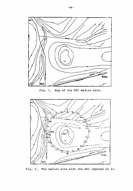
All of this led to the marvelous median site for the SSCshown in Fig. 1. Now the topography and the highways reallydon't exist anywhere except on the drawing and in the minds ofthe creator, but they illustrate the factors that are importantin a reasonable site for the sse. The sort of site illustratedis one where there is a crest in the topography with drainagecoming away from the high ground. Notice that there is aninterstate highway as well as a pUblic service corridor. Thiscorridor contains not only the interstate but also a 230 KV powerline and a railroad right-of-way. Parenthetically, off the mapwhere the branch line railroad joins the main line railroad thereis a natural gas pipeline. Again, that is characteristic of whatone finds today in pUblic utilities. There is a state highwayserving the north-south axis as well as a county road on thesite. There are also various farm roads and other gradedaccesses that are not shown on the site plan but are in factincluded in the utilization of this site when the machine issuperimposed on it. The spirit is to not pave what one doesn'thave to pave when the facility is put into place. Later it willturn out that the access roads that are put in are really minimalin nature and are only to get to those areas where there is ahigh service demand for access.
-46-
Fig. 1. Map of the sse median site.
Fig. 2. The median site with the sse imposed on it.
-47-
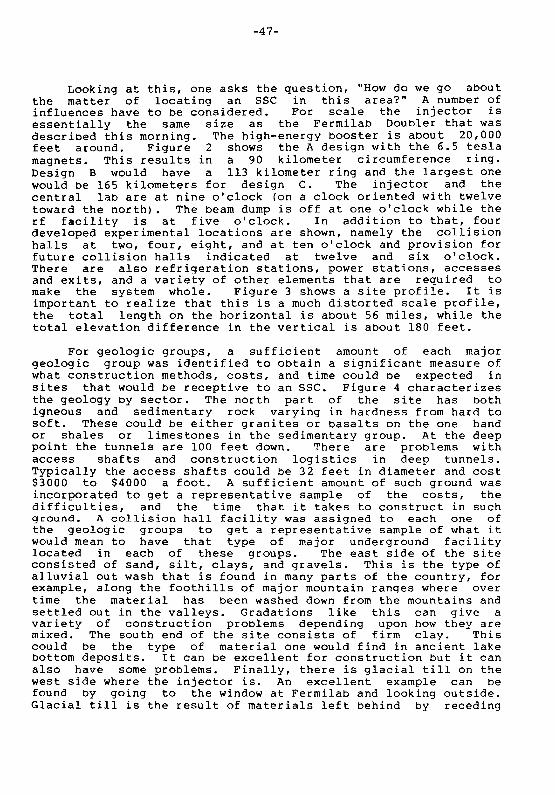
Looking at this, one asks the question, "How do we go aboutthe matter of locating an sse in this area?" A number ofinfluences have to be considered. For scale the injector isessentially the same size as the Fermilab Doubler that wasdescribed this morning. The high-energy booster is about 20,000feet around. Figure 2 shows the A design with the 6.5 teslamagnets. This results in a 90 kilometer circumference ring.Design B would have a 113 kilometer ring and the largest onewould be 165 kilometers for design C. The injector and thecentral lab are at nine o'clock (on a clock oriented with twelvetoward the north). The beam dump is off at one o'clock while therf facility is at five o'clock. In addition to that, fourdeveloped experimental locations are shown, namely the collisionhalls at two, four, eight, and at ten o'clock and provision forfuture cOllision halls indicated at twelve and six o'clock.There are also refrigeration stations, power stations, accessesand exits, and a variety of other elements that are required tomake the system whole. Figure 3 shows a site profile. It isimportant to realize that this is a much distorted scale profile,the total length on the horizontal is about 56 miles, while thetotal elevation difference in the vertical is about 180 feet.
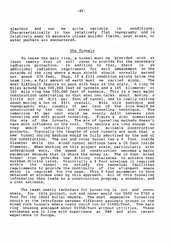
For geologic groups, a sufficient amount of each majorgeologic group was identified to obtain a significant measure ofwhat construction methods, costs, and time could be expected insites that would be receptive to an SSC. Figure 4 characterizes~he geology by sector. The north part of the site has both19neous and sedimentary rock varying in hardness from hard tosoft. These could be either granites or basalts on the one handor shales or limestones in the sedimentary group. At the deeppoint the tunnels are 100 feet down. There are problems withaccess shafts and construction logistics in deep tunnels.Typically the access shafts could be 32 feet in diameter and cost$3000 to $4000 a foot. A sufficient amount of such ground wasincorporated to get a representative sample of the costs, thedifficulties, and the time that it takes to construct in suchground. A collision hall facility was assigned to each one ofthe geologic groups to get a representative sample of what itwould mean to have that type of major underground facilitylocated in each of these groups. The east side of the siteconsisted of sand, silt, clays, and gravels. This is the type ofalluvial out wash that is found in many parts of the country, forexample, along the foothills of major mountain ranges where overtime the material has been washed down from the mountains andsettled out in the valleys. Gradations like this can give avariety of construction problems depending upon how they aremixed. The south end of the site consists of firm clay. Thiscould be the type of material one would find in ancient lakebottom deposits. It can be excellent for construction but it canalso have some problems. Finally, there is glacial till on thewest side where the injector is. An excellent example can befound by going to the window at Fermilab and looking outside.Glacial till is the result of materials left behind by receding

-48-
Nor1h Geological SectorRock Tunnel
EastGeological
Rock SectorCut and Soft Ground
I Cover Tunnel
!1t%:"C:Sff~o 10 20 28
Circumference (Miles)
West GeologicalSector
Cut and Cover
t .;:.: , :.:;.;.:.:.:.:.:·f:·:·:· ,:,·Y:':'l·:·:·:·;t , ·.· ·i } ·.·.·.·.··.·c··. ":':X:" ..:.:.;.f ..:..:..$ ....•.$ j
...............,.".,.,., ",., :::',:, ,.,.,.'.".,.,. """"""""""::·1
565040
Circumference (Miles)
28 30
East Geological SectorSoft Ground Tunnel
South Geological SectorSoil Cut and Cover
Fig. 3. Distorted profile of site to show angulation of themedian site. The elevation difference is on the order of100 feet which the total horizontal axis extends for 56 miles.
North 0e0I0gIc8l Sector
(Type I) 12.0 Miles Soft SheleHard Rod< (Type I) 5.4 Miles
~Ig>eous, Umestone. / ~:Hard Sandstone,ShoIcrete l.i1ing Future / (9 It. 1.0.)
(10 It. 1.0.) CH-12:J/ /-,@ Abort~,,® 0)
.~ ~~CH·l0 @) &~ ® CH-2w_ 0e0I0gIc8l 'b' bel~ 8ector
8ector q.., Oayey Sill wiIh
(Type I) 10.5 Miles ® Sand and GravelCut and Cove< Precast SegmentalGlacial n. Precast l.iling (10 It. 1.0.)Pipe (9 It. 1.0.) a\ fi\ (Type I) 13.1 Miles
CH-8 ~ ~ CH-4 Sottground T'-'Vl8Iing
/
,0 C?utur~~6~~">South QeoIogIcaI SectorSbH to Hard ClayPrecast Pipe (9 HID )(Type I) 14.9 Miles Cut and Cover
Fig. 4. Geologic character and main ring tunnel types.
-49-
glaciers and can be quite variable in conditions.Characteristically it has relatively flat topography and isrelatively easy to excavate unless boulder fields, peat areas, orwater pockets are encountered.
The Tunnels
To house the main ring, a tunnel must be provided with atleast twenty feet of soil cover to provide for the necessaryradiation protection. In addition to that, there is anadditional radiation requirement for soil embankment to theoutside of the ring where a muon shield should normally extendout about 270 feet. Thus, if a fill condition exists below thebeam line, a fair amount of earth must be carried along. Themost difficult feature to work with here is the scale. A ring 56miles around has 300,000 feet of tunnels and a 165 kilometer or103 mile ring has 550,000 feet of tunnels. This is a very majorconstruction undertaking so that when one talks about moving alittle bit of dirt per foot of tunnel, one is really talkingabout moving a lot of dirt overall. With this geologic andtopographic mix, roughly 55 per cent of the site would beconstructed by the cut and cover tunneling technique. Theremaining 45 per cent would be evenly split between rocktunneling and soft ground tunneling. Figure 4 also summarizesthe mix of the tunnels. The mix of tunneling methods doesn'thave much influence on the cost. The sectors are long enough sothey would individually constitute suitable constructionprojects. Typically the lengths of rock tunnels are such that anew tunnel boring machine would be fully amortized by the end ofthe construction. The cut and cover tunnel has a 9 foot insidediameter while the mined tunnel sections have a 10 foot insidediameter. When working on this project scale, particularly withunderground work, the speed of construction becomes a majorparameter because that is where the money is. The 10 foot minedtunnel size provides the driving tolerances to achieve nearmaximum driving rates. Essentially a 9 foot envelope is requiredwithin the tunnel to satisfy the technical facilitiesrequirements to provide the continuity of the alignment spacewhich is required for the beam. This 9 foot parameter is thusObtained at minimum cost by this approach. All of this tunnelinginformation then leads to a construction program, a schedule, anda cost estimate.
The least costly technique for tunneling is cut and coverwhere, for this project, cut and cover would run $600 to $700 afoot for the ideal burial depths. The most expensive tunnelingoccurs at the interfaces between different geologic groups in themined rock tunnels where costs could run to $1600/foot. The mainring housing averaged about $1050/foot without utilities. Theseestimates are in line with experience at PEP and also recentexperience in Europe.

-50-
Figure 5 shows what the cross section might look like forthe cut and cover case. There are several enclosure materialsthat could work but a precast pipe has been used here. It isestimated that 400 feet of pipe a day could be installed in atrench and back filled using a forward projection pipe layingtechnique. That's moving fast, but that's what can be done if acontractor sets up not just a pipeline operation but in fact, aproduction operation.
Observing the tunnel cross section, the primary device inthe enclosure is the beam magnet package which is placed alongthe inside surface of the tunnel, to the right in this view. Theinjector, also in a tunnel, is located on the inside of the mainring with a magnet package mounted along the outside surface ofthe housing. If this were design B, there would be a doublemagnet package. The utilities are kept on one side. Theyinclude a helium gas line, water for heat rejection as well asfire protection, and 480 volt power inside the tunnel. The 480volt power goes into mini power centers that are set out at 100meter intervals. At those points it is broken down into 120volts, a 408 V welding circuit and some other housekeepingcircuits. The other side of the tunnel has communications andfire alarm circuits. This cross section provides for both aplace for a person in a lay down space to work along the beamline, as well as a way of moving about by an electric-poweredcart. Obviously the space inside must be used efficiently. Thesize of the interior space was determined both by considering thesize that would be economic to construct as well as the sizenecessary on a functional basis to provide for what goes oninside the tunnel. Notice that there is sufficient room for twoway traffic.
If a shotcrete lined rock tunnel was used it would not be awater tight tunnel, but it also would not be a wet one. The samegeneral configuration would be used but a 10 foot 1D tunnel wouldbe used to provide the 9 foot clearance envelope. The softground tunnel would be very similar except the tunnel would be ofprecast concrete tunnel liners jacked into place and sealedwithout any further finish. Considering each one of these typesof tunnels from the point of view of the supply of the variousmaterials that will be required and doing some extrapolation oflengths and size, it is clear some very significant supplycontracts will be required to make this project go. Figure 6illustrates what the inside of the tunnel might look like whenall facilities are in place. This is not too different from thephotographs of the existing Fermilab facilities.
Other Underground Features
Around the main ring there's more than just athough the tunnel is the major cost feature.twelve refrigeration compressor stations equally
tunnel, evenThere are alsospaced around

-51-
Fig. 5. Tunnel cross section fortechnique. The inner diameter is 9 feet.
the cut and cover
Fig. 6. Perspective view of the main ring tunnel.

-52-
the ring with shaft accesses to the tunnel. The power suppliesand the refrigeration plants are combined into single stations.There is one radiofrequency facility (rf) in a tunnel enlargementfor boosting the beam energy. There is a single beam dumplocated in a series of short tunnels and underground rooms. Theinjector facility is at the nine o'clock position located in fivemiles of tunnel. There are twenty-four tunnel access and exitpoints around the ring which also provide for ventilati9n andfacilities for moving small equipment in and out. The power isprovided from the 230 KV supply to a major substation at the sitewhere it is broken down and distributed around the ring.
Figure 7 illustrates a typical refrigerator/compressor andpower station. The typical refrigeration station is a 50 foot by132 foot building containing a refrigerator/compressor and apower station. Outside there are a couple of additionalbuildings. There is a shaft going down to the tunnel that hashelium facilities and a dewar in it. There is also a tank farmfor helium storage. The amount of helium that this wholefacility requires is quite remarkable and tests the capacity toproduce it. The shafts at the compressor stations are 26 to 30feet in diameter. The accelerator beam is running on the insideof the tunnel housing so that the passage way is accessible onthe outside. Consequently the egress for people is on theoutside of the tunnel down an 18 to 20 foot diameter shaft.Double 90 degree dog legs are provided for radiation protectionand the cross section is adequate for ventilation of the tunnel.
Figure 8 illustrates a typical collision hall, a very majorunderground facility. The central hall is some 70-75 feet on aside with a 60 foot ceiling, and a forward and a backward areathat are each 40 by 40 feet with a 50 foot ceiling. All of thatis buried underground with at least 20 feet of filIon top of it.There is also a bypass tunnel passageway that allows thefacilities and personnel in the beam housing to move around thecollision hall. There are hatches on the back side of the bypasstunnel by which additional magnets could be lowered down by acherry picker on to a traveler in the tunnel and moved around thering if it was necessary to replace one of the magnets. Many ofthese features have proven to be effective at Fermilab with theBO and DO facilities. There is an assembly area at the samefloor elevation as the collision hall to give space to lay downcomponents in the course of putting together the experiment. Anenormous door, some twenty feet thick, is provided to separatethe two areas. At the next level there is a large assemblybuilding for preparation. Access is through a floor opening tothe assembly area below. All of this is served by a fifty toncrane. There are a series of offices and floors for thecomputing area, computer, other equipment, and personnel space onthe outside bay of the building. The building is about 120 feetby 300 feet, a fairly large enclosure, but sized to thenecessities of one of these research facilities. Recognize thatit would probably be at least ten miles from where the

-53-
Fig. 7. Aerial view of refrigerator and power supply building.
Fig. 8. Aerial view of staging building and cut away ofcollision hall. The staging building is 125 feet x 300 feet.
-54-
experimental area is located to the central laboratory as aresult of the scale of the facility. It could be as much asthirty five miles back to the main laboratory from a collisionhall on the other side of the ring. That means this has to beessentially a self-sustaining operation. There would probably bepeople here who would work here and nowhere else if they workedat the site.
Consideration was given to the fact that these buildings maybe buried at different depths. Each collision hall was treatedin terms of its actual relationship to the geology and thetopography.
The Services
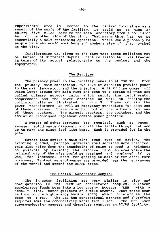
The primary power to the facility comes in at 230 KV. Fromthe primary main sUbstation, two 13.8 KV circuits provide powerto the main laboratory and the injector. A 69 KV line comes offwhich loops around the main ring and goes to a series of what arecalled primary network units which supply the refrigeratorcompressors and the power stations as well as feeding thecollision halls as illustrated in Fig. 9. These contain thepower transformers as well as emergency generators for each oneof these stations. There is nothing out of the ordinary in anyof these systems. The circuit breakers, the switches, and theisolation techniques represent common power practice.
A number of other services are required, such as water,sewage, solid waste disposal, and all the little things that addup to make the place feel like home. Each is provided for in theplan.
Rather than devise a main ring road type of design, theexisting graded, perhaps graveled road services were utilized.This also helps from the standpoint of being as good a neighboras possible by building the machine into an area where theoriginal use of the site could be retained and employed if itwas, for instance, used for grazing animals or for other farmpurposes. Protective enclosures are provided near the entrancesof the tunnel and around the RC/PS areas.
The Central Laboratory Complex
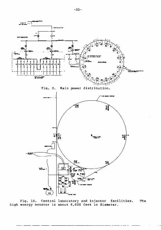
The injector facilities are very similar in size andconfiguration to the Fermilab accelerator complex. A linearaccelerator feeds beam into a low energy booster (LEB) with a"small" ring, three quarters of a mile around. That feeds beamin turn to the high energy booster (HEB) which accelerates thebeam to I TeV. The LEB has conventional magnets and thereforerequires some low conductivity water facilities. The HEB usessuperconducting magnets and therefore requires an RC/PS facility.
-55-
~., c-~
"
MI.............
-E-":1::
Fig. 10. Central laboratory and injector facilities. Thehigh energy booster is about 6,000 feet in diameter.

-56-
The beam is transferred directly from the HEB into the main ringas shown in Fig. 10.
Facilities are required at the central lab campus area toprovide sufficient work space and support for some 3000 people,as shown in Fig. 11. There are six assembly buildings, four shopbuildings, two service support buildings, and various other kindsof support facilities. Figure 12 shows a conceptual rendering ofthe major building for the central office and laboratory space.It is laid out on a simple rectangular plan which readily permitsexpansion. The building is statistically similar to the Fermilabhighrise except that a four story building is considered so thata light steel framing approach can be used which is more economictoday. There are 380,000 square feet or so of space in thisbuilding. Both passive and active solar techniques are employedas a means of exploiting the available solar energy.
The Schedule
Figure 13 shows the schedule, in part, for conventionalconstruction. A period on the order of six years is shown. Adetailed schedule of all of the work to be done was put togetherduring the design study. An obligation curve, Fig. 14, wasdevised from the construction schedule. While it is an ambitiousinvestment program, it is not without precedence in the area ofpUblic works construction. About a quarter of a billion dollarsa year would be put into civil construction. As an example, anumber of transit projects in this country have put that much ormore work in place in a one year period.
For the A design (6.5 tesla magnets) the cost of theconventional facilities was put at about 875 million dollarswhile the B facilities were estimated to be on the order of 1billion dollars and the C facilities would be on the order ofabout 1.4 to 1.5 billion dollars. That is just extrapolating onthe basis of the median site and the unit prices that came out ofthe exercise. Those numbers are being reviewed by DOE and theymay be changed in the final DOE report.
With all this information, it would be possible to startlooking for a site now. Of course, there is still a lot ofdevelopment to be done and that development may result in furtherdefinitions that will modify some of the needs and some of therequirements that will come back into the conventional side.However, it might be prudent to get underway with site selectionsoon. The lead time that it takes to produce the environmentalimpact reports and to go through the site selection process withthe kind of contest that could be generated in that decision willsimply take time. It could well be a time equivalent to the R&Dtime for the technical facilities.

-57-
Fig. 11. Aerial view of the central laboratory campuscomplex. The circle in the foreground is the low energy booster.
r/
Fig. 12. South facade of the central laboratory.

-58-
~ DESCRIP liON 1P;::'r~ YL-pp2 ~ ~ Y"........5 ~
11PV11N1:En_LDI$1fJN R ~
~ rlN"Lb/!~I6N 13 ~!_~~-~~~~~-~~--.----_.
~ CONS71ft/CT/ON If_Nr- C 1,,-..ROvRNCIAlwrR/G...s 1-
I\!>
l10vRNCIE W"TER Z...
I. 2.1./ I~ C__RfRLUNJ.rACILmll
1.3.1.1 !oI~ INncro"r-.cILITlcs..
31---':--"- I;'l: .../. "1.1./ loll 1f"INRJ_Rccr.rRCIL.
I.S-/./ I Ex~"'HrNTIILrl'tCl'" ~~ - ... ....~ ~~~
1."1.1.2·2 ~ 5EGf«'NTIiLLINfNf; ~",,,, - -~ t
/."1.1.2..3 ~ CONCRETe PII'I!I 0," -Q;,
f1,LIESTON£S ~~~~~~t>_~a/7_" rl-.rD">~
~£f1J,i: ffl/f{1U(tfUFINR£IX5I&IV
LEGEND--=-ADVANCE FINAL Z>ESIGN
DETAILED DlSIGH_ ADV£I!TISE _ AWARD
o TSIo4· TUlIMl saltINe MACHINE
Fig. 13. Project planning and scheduling.
900
800
700
!600g~5oo.5-400
300
200
100
o
Yea' 1 Yea' 2 Yea' 3 Yea' 4 Yea' 5 Yea' 6
---r-....I
r-I
r-
r...I
~
IJ
Fig. 14. Obligation curve for the sse project.

Conclusion
The SSC is a feasible project and its future is possible.Its conventional facilities can be designed and constructedefficiently and cost effectively today, using today's men,materials, and methods. Let us hope that the priorities to beset include the SSC.