Fabrication and Design of Structural Members
36
USOO6272447B1 (12) United States Patent (10) Patent N0.2 US 6,272,447 B1 Gavin et al. (45) Date of Patent: Aug. 7, 2001 (54) FABRICATION AND DESIGN OF OTHER PUBLICATIONS STRUCTURAL MEMBERS Levy et al., “Feature—based Design Approach in the Sheet (75) Inventors: Peter Geo?'rey Gavin; Peter Robert Metal Industry”, Proc. 4th Inter. Conf. Computer Integrated Brennan; Thomas William Ellis, all of Man. and Tech, pp. 66—71, Oct. 1994.* Napier (NZ) (List continued on neXt page.) (73) Assignee: Scottsdale Building Systems Limited, Napier (NL) Primary Examiner—Kevin J. Teska Assistant Examiner—Douglas U. Sergent ( * ) Notice: Subject to any disclaimer, the term of this (74) Attorney) Agent) Or Firm_WOrkman, Nydegger & patent is extended or adjusted under 35 Seeley U.S.C. 154(b) by 0 days. (57) ABSTRACT (21) Appl' N05 09/306,082 A method of designing structural members for a building (22) Filed, May 6, 1999 frame using a computer includes the steps of inputting a predetermined plan of the layout and orientation of the (30) Foreign Application Priority Data structural members. This information is then stored. The computer then analyses the stored plan information to pro Oct. 21, 1998 (NZ) ................................................... .. 332446 Vida Speci?cations of length and jointing details for each (51) Int. Cl.7 .................................................... .. G06F 17/50 structural member to enable the structural members made (52) US. Cl. ................................... .. 703/1; 703/6; 700/97; according to speci?cation t9 ?t together to form the frame 700/98; 700/118 The speci?cations of each structural member are outputted (58) Field Of Search ........................ .. 703/1, 6, 7; 700/97, from the Computer In another method of fabricating Struc 700/98, 118, 182; 706/919, 923; 345/964 tural members the members are formed on a forming machine Which also creates the connecting features enabling (56) References Cited the structural members to be assembled as a building frame. A forming machine to fabricate structural members includes U-S~ PATENT DOCUMENTS a memory to store structural member speci?cations of length 4,660,399 4/1987 Suter et a1. .......................... .. 72/181 and jointing features enabling the Structural members to be assembled as a building frame. The forming machine is 5,033,014 * 7/1991 Cawer et a1_ adapted to form each structural member according to the 5,526,628 6/1996 Knudson __ length speci?cation and create the jointing features. In a 5,555,406 * 9/1996 NoZaWa ....... .. method for designing the structural members of building 5,559,708 * 9/1996 TllIIlbllll et al. ..................... .. 292/48 frames a plan of a predetermined layout of the frames including details of frame openings is input into a computer. The layout is analyzed to determine parameter FOREIGN PATENT DOCUMENTS lines and frame opening lines for each frame. The computer program then designs the layout of the orientation of struc tural members for each frame and the plan of the layout and orientation of the structural members for each frame is then output from the computer. 4,858,146 * 8/1989 Shebini .... .. (List continued on neXt page.) 52665/93 12/1993 (AU) . 52666/93 12/1993 (AU) . 0 846 549 A2 12/1997 (EP) . 2 279 594 1/1995 (GB) . WO 87/01977 4/1987 (W0). WO 96/35022 11/1996 (W0) . 14 Claims, 25 Drawing Sheets 0 M30 eachkameimm is by \he an (rammg package use me above Davamners m detemwve mm em langms (or wmm |mntmg - Med, insensd and notched Add completed (we components and the appropriate operatmns 16 0|: Dmduclmh queue Sn!‘ components Into labrlca?nn nrder
-
Upload
amjad-pervaz -
Category
Documents
-
view
12 -
download
0
description
Fabrication and design of structural members
Transcript of Fabrication and Design of Structural Members
USOO6272447B1
(12) United States Patent (10) Patent N0.2 US 6,272,447 B1 Gavin et al. (45) Date of Patent: Aug. 7, 2001
(54) FABRICATION AND DESIGN OF OTHER PUBLICATIONS STRUCTURAL MEMBERS
Levy et al., “Feature—based Design Approach in the Sheet (75) Inventors: Peter Geo?'rey Gavin; Peter Robert Metal Industry”, Proc. 4th Inter. Conf. Computer Integrated
Brennan; Thomas William Ellis, all of Man. and Tech, pp. 66—71, Oct. 1994.* Napier (NZ)
(List continued on neXt page.) (73) Assignee: Scottsdale Building Systems Limited,
Napier (NL) Primary Examiner—Kevin J. Teska Assistant Examiner—Douglas U. Sergent
( * ) Notice: Subject to any disclaimer, the term of this (74) Attorney) Agent) Or Firm_WOrkman, Nydegger & patent is extended or adjusted under 35 Seeley U.S.C. 154(b) by 0 days.
(57) ABSTRACT
(21) Appl' N05 09/306,082 A method of designing structural members for a building (22) Filed, May 6, 1999 frame using a computer includes the steps of inputting a
predetermined plan of the layout and orientation of the (30) Foreign Application Priority Data structural members. This information is then stored. The
computer then analyses the stored plan information to pro Oct. 21, 1998 (NZ) ................................................... .. 332446 Vida Speci?cations of length and jointing details for each
(51) Int. Cl.7 .................................................... .. G06F 17/50 structural member to enable the structural members made
(52) US. Cl. ................................... .. 703/1; 703/6; 700/97; according to speci?cation t9 ?t together to form the frame 700/98; 700/118 The speci?cations of each structural member are outputted
(58) Field Of Search ........................ .. 703/1, 6, 7; 700/97, from the Computer In another method of fabricating Struc 700/98, 118, 182; 706/919, 923; 345/964 tural members the members are formed on a forming
machine Which also creates the connecting features enabling (56) References Cited the structural members to be assembled as a building frame.
A forming machine to fabricate structural members includes U-S~ PATENT DOCUMENTS a memory to store structural member speci?cations of length
4,660,399 4/1987 Suter et a1. .......................... .. 72/181 and jointing features enabling the Structural members to be assembled as a building frame. The forming machine is
5,033,014 * 7/1991 Cawer et a1_ adapted to form each structural member according to the 5,526,628 6/1996 Knudson __ length speci?cation and create the jointing features. In a 5,555,406 * 9/1996 NoZaWa ....... .. method for designing the structural members of building 5,559,708 * 9/1996 TllIIlbllll et al. ..................... .. 292/48 frames a plan of a predetermined layout of the
frames including details of frame openings is input into a computer. The layout is analyzed to determine parameter
FOREIGN PATENT DOCUMENTS lines and frame opening lines for each frame. The computer program then designs the layout of the orientation of struc tural members for each frame and the plan of the layout and orientation of the structural members for each frame is then output from the computer.
4,858,146 * 8/1989 Shebini .... ..
(List continued on neXt page.)
52665/93 12/1993 (AU) . 52666/93 12/1993 (AU) .
0 846 549 A2 12/1997 (EP) . 2 279 594 1/1995 (GB) .
WO 87/01977 4/1987 (W0). WO 96/35022 11/1996 (W0) . 14 Claims, 25 Drawing Sheets
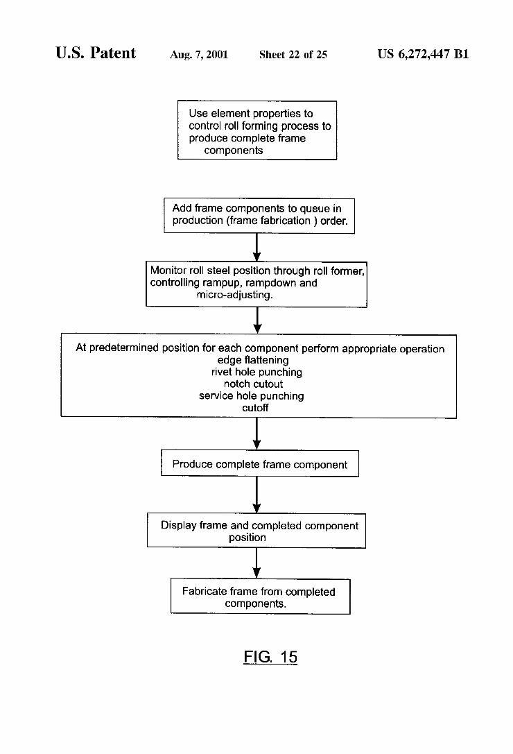
0 M30 eachkameimm is by \he an (rammg package
use me above Davamners m detemwve mm em langms (or wmm |mntmg - Med, insensd
and notched
Add completed (we components and the appropriate operatmns 16 0|:
Dmduclmh queue
Sn!‘ components Into labrlca?nn nrder

US 6,272,447 B1 Page 2
U.S. PATENT DOCUMENTS
5,627,763 * 5/1997 Carlson .................................. .. 703/1
5,651,230 7/1997 Knudson 52/7481 5,689,435 * 11/1997 Umney et al ..... .. 703/1
5,761,674 * 6/1998 Ito ................ .. 707/104
5,940,309 * 8/1999 White et al. 703/1 5,983,010 * 11/1999 Murdock et al. ...................... .. 703/1
* 6,014,503 1/2000 Nagata et al. ......................... .. 703/1
OTHER PUBLICATIONS
Moradi et al., “Geometry—based Part Grouping for Assem bly Planning”, Proc. of the 1997 IEEE Inter. Symp. on Assembly and Task Planning, pp. 281—286, Aug. 1997.* Radack et al., “Positioning Features Within the Rapid Design System”, Systems Engineering, 1991., IEEE International Conference on , 1991 pp.: 38—41, Aug. 1991.* Liu et al., “CAD—Based Automated Machinable Feature Extraction”, 27th ASILOMAR Conf. on Signals, Systems and Computers, vol. 1, pp. 558—562, Nov. 1993.*
Horvath et al., “Generation of Manufacturing Process Model Entities”, Inter. Conf. on Intelligent Processing Systems, vol. 1, pp. 824—828, Oct. 1997.* LaZaro et al., “Automated Design of Maching Fixtures: Tolerance and Sequential Operations”, Intelligent Systems Engineering, vol. 1, Issue 2, pp. 172—184, Winter 1992.* Hoffmann et al., “A Road Map to Solid Modeling”, IEEE Trans. on Visualization and Computer Graphics, vol. 2, No. 1, Mar. 1996, pp. 3—10.* Werkman et al., “Design Fabricator Interpreter System: Evaluating Alternative Connection Con?gurations” Sixth Conf. on Arti?cial Intelligence for Applications, vol. 1, pp. 153—159, May 1990.* Werkman, K.J., “Negotiation in DAI as an Infrastructure Component for Collaborative Enterprises”, Proc. Second Workshop of Enabling Tech: Infra. for Collab. Enterprises, pp. 104—117, Apr. 1993.*
* cited by examiner

U.S. Patent Aug. 7, 2001 Sheet 1 0f 25 US 6,272,447 B1
14
/ M 12 A 13 12
11
F|G.1a
13 11
16 /
14 0/
12 ,/ K10
10
/ 12\ \
11 /
15 15 /16 \ / 0/
15/
14
16 1 / 3 0/
FIG. 1b FIG. 1c

U.S. Patent Aug. 7, 2001 Sheet 2 0f 25 US 6,272,447 B1

U.S. Patent Aug. 7, 2001 Sheet 3 0f 25 US 6,272,447 B1
12L /
M
25/
FIG. 20
U.S. Patent Aug. 7, 2001 Sheet 4 0f 25 US 6,272,447 B1
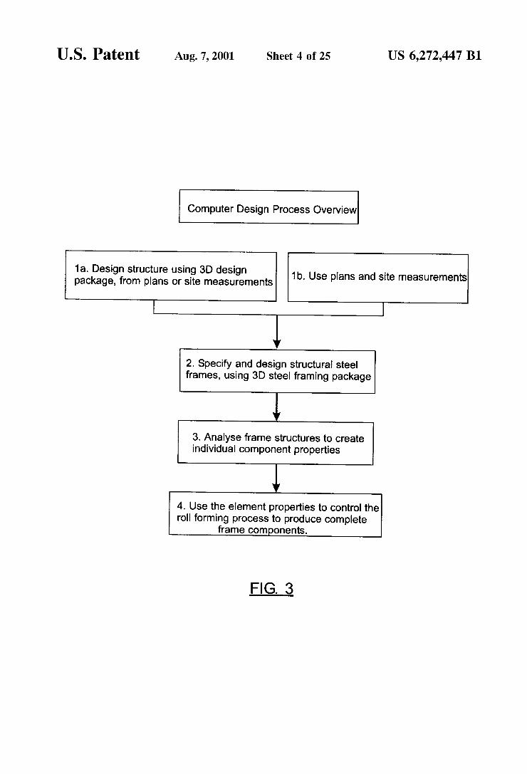
Computer Design Process Overview
1a. Design structure using 3D design package, from plans or site measurements
L |
1b. Use plans and site measurements
Y
2. Specify and design structural steel frames, using 3D steel framing package
1 3. Analyse frame structures to create individual component properties
i 4. Use the element properties to control the roll forming process to produce complete
frame components.
FIG. 3
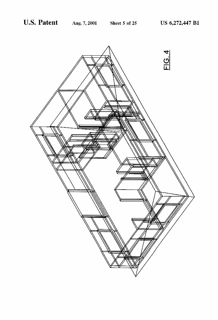
U.S. Patent Aug. 7, 2001 Sheet 5 0f 25 US 6,272,447 B1
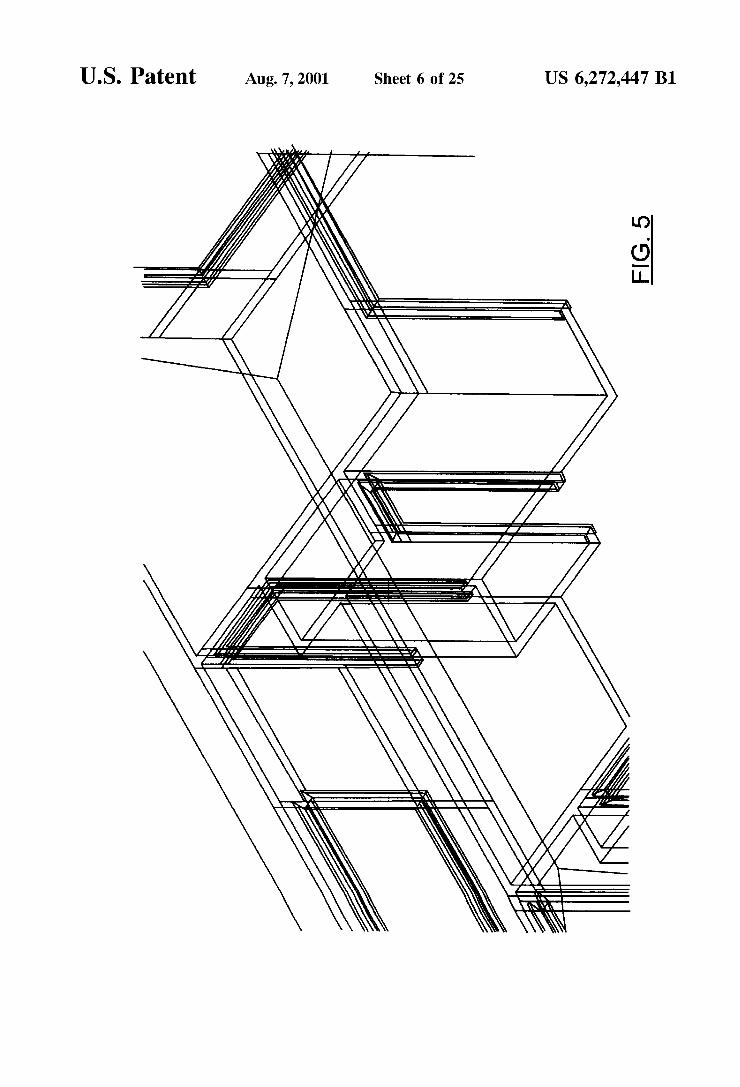
U.S. Patent Au .7 2001 Sheet 6 0f25
/I//
\ 9N
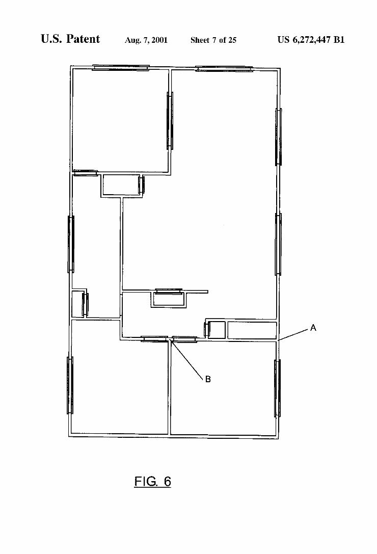
U.S. Patent Aug. 7, 2001 Sheet 7 0f 25 US 6,272,447 B1
I ‘a c»
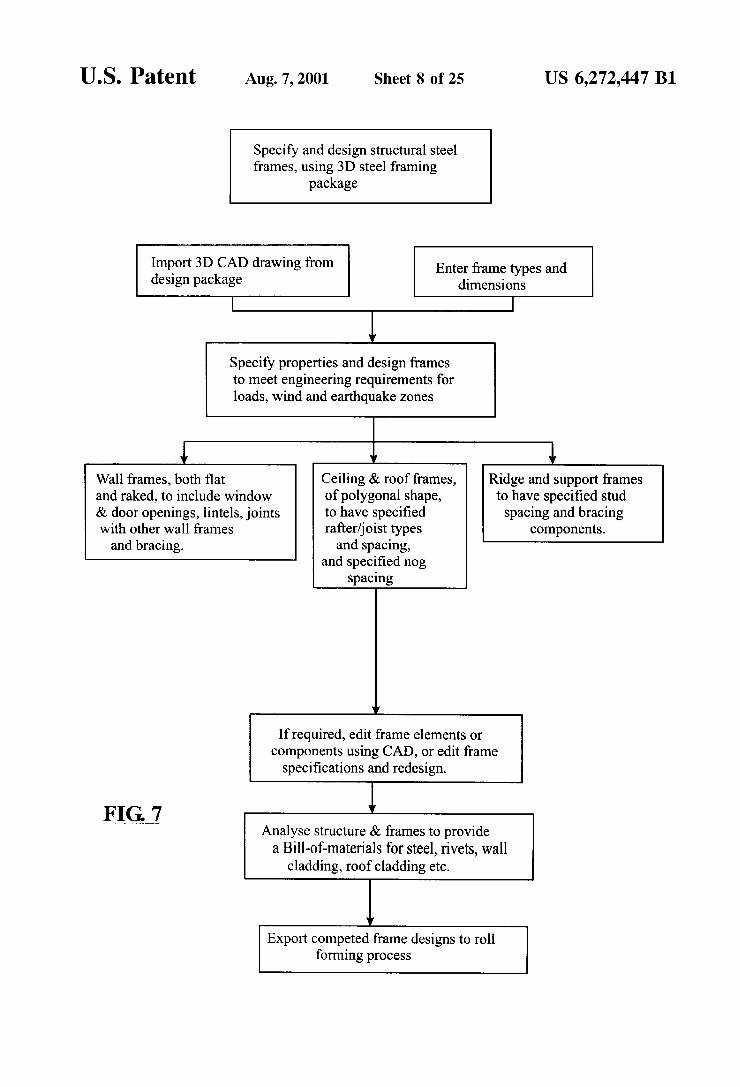
U.S. Patent Aug. 7, 2001 Sheet 8 0f 25 US 6,272,447 B1
Specify and design structural steel frames, using 3D steel framing
package
Import 3D CAD drawing from design package
Enter frame types and dimensions
V
Specify properties and design frames to meet engineering requirements for loads, wind and earthquake Zones
v ‘l v
Wall frames, both ?at Ceiling & roof frames, Ridge and support frames and raked, to include window of polygonal shape, to have speci?ed stud & door openings, lintels, joints to have speci?ed spacing and bracing with other wall frames rafter/joist types components. and bracing. and spacing,
and speci?ed nog spacing
If required, edit frame elements or components using CAD, or edit frame speci?cations and redesign.
V ElGJ Analyse structure & frames to provide a Bill-of-materials for steel, rivets, wall
cladding, roof cladding etc.
V
Export competed frame designs to roll forming process

U.S. Patent Aug. 7, 2001 Sheet 9 0f 25 US 6,272,447 B1
Specify & design structural steel frames, using 3D steel framing software
Import 3D CAD drawing Enter frame types and from design package dimensions
v
Specify properties and design frames to meet engineering requirements for loads, wind and earthquake zones.
/ 1 Wall frames, ?at and raked Ceiling & roof frames Ridge and support frames top plates, to include of polygonal shape to have speci?ed windows & door openings, to speci?ed stud spacing and lintels, joints with other wall rafter / jOiSt Spacing, bracing components. frames and bracing. rafter /joist type
and nog spacing.
V
If required, edit frame elements or components using CAD tools or edit frame speci?cations and rebuild
V
Analyse structure and frames to provide a ‘Bill-of-Materials’ for steel, rivets, wall cladding, etc..
V
Export completed frame designs in graphical form to the roll forming processing
FIG. 7A

U.S. Patent Aug. 7, 2001 Sheet 10 of 25 US 6,272,447 B1
Wall frame design - perimeter & opening analysis for GcadZ
V
Get user input of frame outline footprint in plan view mode. This is limit points from the dxf lines.
V
Scan the dxf lines and determine the vertical height of the frame along the footprint outline.
Som both frane fdoes ( the 3D shcpe on each side of the outlined frdne ),cnd find interseding dxf ‘T R M‘ items that represent the opening ( door & window ) positions md sizes md that reach from one face of the frcrne to the other.
v v
Doors - only one ‘TRIM’ Windows - two ‘TRIM’
item at a point along the items at a point along the frame. This one item frame. One item represents represents the opening height. the top of the opening, the other
the bottom.
v
Use the frame height and opening sizes and positions to design the items that ?ll the frame. Opening details, studs, nogs & braces above lintels
FIG. 7B
U.S. Patent Aug. 7, 2001 Sheet 11 0f 25 US 6,272,447 B1
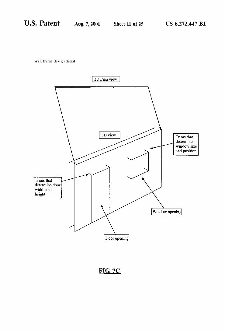
Wall frame design detail
2D Plan view
@Zl Trimsthat determine
4:// window size and position
// Trims that / determine door width and height
Window opening
Door opening
FIG 7C

U.S. Patent Aug. 7, 2001 Sheet 12 of 25 US 6,272,447 B1
Wall frame design-perimeter & opening analysis for gcad3
v
Get user input of frame face vertex points in 3D view mode
l Use the selected vertex coordinates to build a mathematical equation of the wall planes
Scan these planes for intersecting ‘TRIM’ items that represent openings for doors and windows, that go from one face to the other.
Door - One ‘TRIM’ item at Window ' Two ‘TRIM, a given position. Items at any position.
Use the frame plane size and the opening positions to design the frame by adding Opening details, studs, nogs, braces for lintels.
FIG. 7D
U.S. Patent Aug. 7, 2001 Sheet 13 0f 25 US 6,272,447 B1
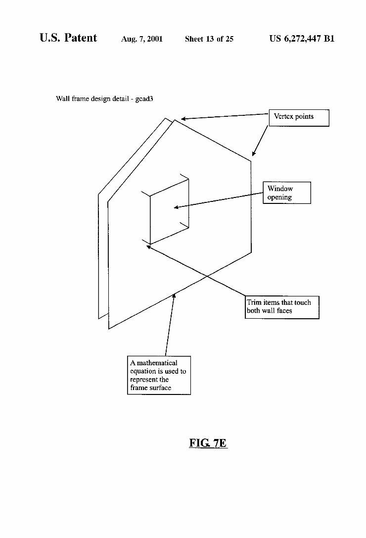
Wall frame design detail - gcad3
<_ Vertex points
Window / .
opening
Trim items that touch both wall faces
/
A mathematical equation is used to represent the frame surface
FIG. 7E
U.S. Patent Aug. 7, 2001 Sheet 14 0f 25 US 6,272,447 B1
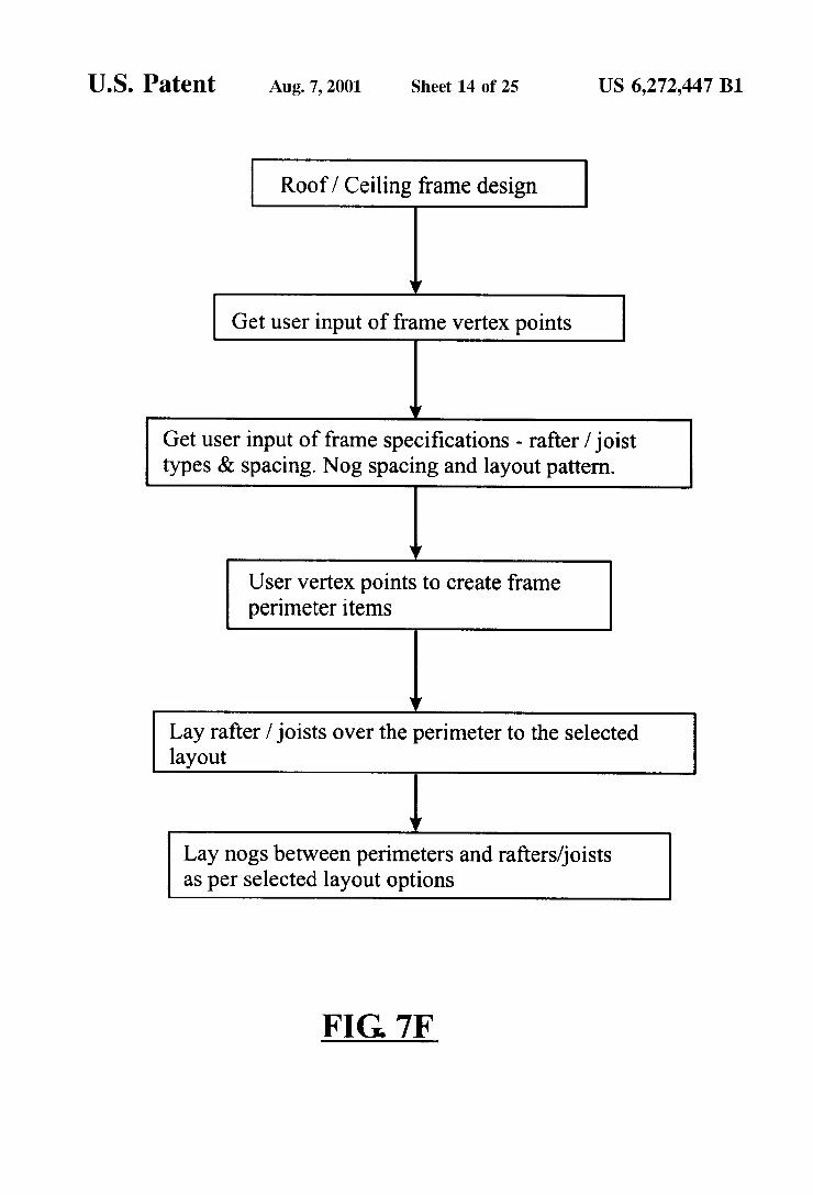
Roof / Ceiling frame design
Get user input of frame vertex points
Get user input of frame speci?cations - rafter / joist types & spacing. Nog spacing and layout pattern.
l User vertex points to create frame perimeter items
Y
Lay rafter / joists over the perimeter to the selected layout
Lay nogs between perimeters and rafters/joists as per selected layout options
FIG. 7F
U.S. Patent Aug. 7, 2001 Sheet 15 0f 25 US 6,272,447 B1
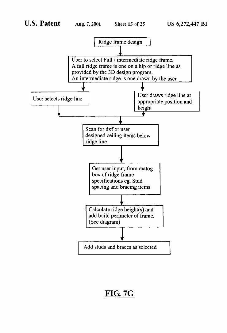
Ridge frame design
1 User to select Full / intermediate ridge frame. A full ridge frame is one on a hip or ridge line as provided by the 3D design program. An intermediate ridge is one drawn by the user
i l User draws ridge line at appropriate position and
1 height i
User selects ridge line
Scan for dxf or user designed ceiling items below ridge line
Get user input, from dialog box of ridge frame speci?cations eg. Stud spacing and bracing items
l Calculate ridge height(s) and add build perimeter of frame. (See diagram)
1 Add studs and braces as selected
FIG. 7G

U.S. Patent Aug. 7, 2001 Sheet 16 0f 25 US 6,272,447 B1
Ridge height calculation
Ridge line I
Ridge frame (Full). Intermediate ridge Height is calculated frame from ridge height
and ceiling position
I
Ceiling frame
FIG. 7H
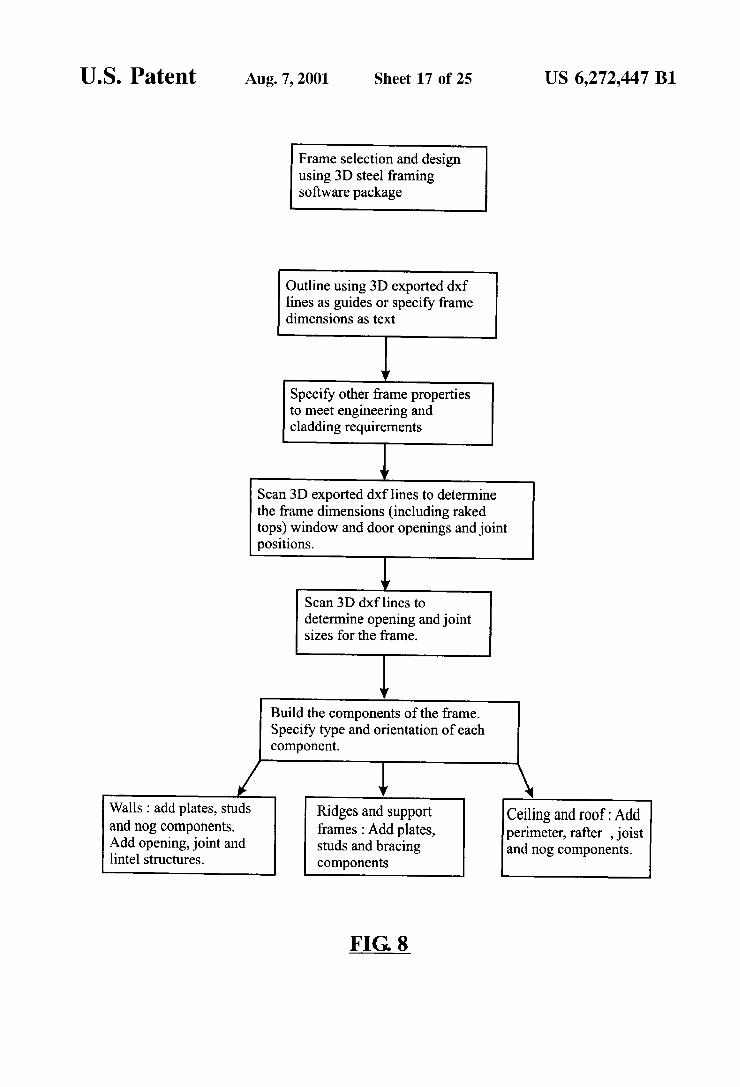
U.S. Patent Aug. 7, 2001 Sheet 17 of 25 US 6,272,447 B1
Frame selection and design using 3D steel framing software package
Outline using 3D exported dxf lines as guides or specify frame dimensions as text
l Specify other frame properties to meet engineering and cladding requirements
1 Scan 3D exported dxf lines to determine the frame dimensions (including raked tops) window and door openings and joint positions.
Scan 3D dxf lines to determine opening and joint sizes for the frame.
l Build the components of the frame. Specify type and orientation of each component.
Walls : add plates, studs and nog components. Add opening, joint and lintel structures.
Ridges and support frames : Add plates, studs and bracing components
Ceiling and roof : Add perimeter, rafter , joist and nog components.
FIG. 8
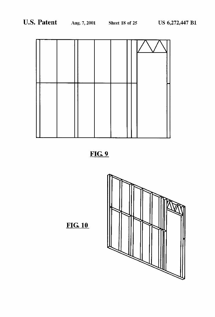
U.S. Patent Aug. 7, 2001 Sheet 18 0f 25 US 6,272,447 B1
AA
FIG. 9
\\F % §§
"LN
\ FIG. 10 >§