F200 Handbook - · PDF fileASL F200 Visit the downloader. F 2 0 0 Menu Clear Enter ... The...
73
Precision Thermometer F200 Issue 3 Operator's Handbook Smart Probe Editor Handbook Firmware Download Quick Start Guide Smart Probe Editor Software Smart Probe Conversion Kit Visit the ASL web site
Transcript of F200 Handbook - · PDF fileASL F200 Visit the downloader. F 2 0 0 Menu Clear Enter ... The...

Precision Thermometer
F200
Issue 3Operator's Handbook
Smart Probe Editor Handbook
Firmware Download
Quick Start Guide
Smart Probe Editor Software
Smart Probe Conversion Kit
Visit the ASL web site

Precision Thermometer
Downloading the latest F200 instrument firmware
This utility will allow you to access the latest firmware for the F200.
Ensure that your computer is connected to the Internet.
Press the button below and follow the instructions on screen.
After you have successfully downloaded the self extracting files to yourcomputer, you must ensure that your F200 is connected to a computer usingthe correct RS232 cable which must be a 9-way female to 9-way female nullmodem type.
You will require a user name and password. Contact thesales office for more information.
ASL
F200
Visit the downloader

F
2
0
0
Menu
Clear
Enter
Ch UnitsHoldA-B Zero
°C
Ω °F
K
o
Precision Thermometer
+27.809CCh1
Units
°C
Ω °F
K
F200 Quick start guide
s
Channel selected Units
UNIT Selects measurement display units: °C, °F, K, Ω
MENU Cycles through the main menu functions of the instrument.
Each subsequent press ofthe unit button cycles the readings between
°C - °F - K - Ω
HOLD Display hold, trigger continuous measurement or hold.
SMART probe is connected
Passive probe is connected
ZERO Nulls the display at the current reading and displays measured values relative to the nulled value.
A-B Relative measurement function displays the difference between the ChA and ChB inputs
CH Selects and displays measurement channel 1 to 8CH Selects and displays measurement channel 1 to 8
CLEAR Clears any data entry errors or min/max statistics
ENTER Saves data entry and returns to previous menu.
TYPES OF PROBE
F200 can accept up to eight thermometer input channels. The 4-wire SMART probes or passive PRTs are connected via the 5-pin DIN sockets located on the instruments top panel for ease of use. SMART probes are automatically detected before each measurement process and are indicated by S on the bottom left hand corner of the display. Passive probes are indicated by a dot.
SMART probes store their calibration data and other useful data in an EEPROM in the probe’s plug which can be plugged into any channel. Passive probes have their calibration data stored in the F200 and can only be used in the channel where you have selected to enter this data.
PASSWORD PROTECTION
User entry to editing the probe calibration (Menu 1) and instrument calibration (Menu 3) are password protected. The user default is 9900, but this can be changed to your own password using any terminal program via the RS232 interface.
THE MENU
Subsequent pressing of the MENU button will cycle the main menu through the top level menu enabling you to configure your F200.
Review/Edit Probe Calibration allows you to review probe calibration and edit probe coefficients. F200 provides 3 standard algorithms for converting resistance to temperature. The choice will depend on the type of PRT and its calibration.
Din (1992):- used for un-calibrated industrial probes with 0.00385 “alpha” value, to provide a conversion of resistance to temperature in accordance with BS EN60751 (ITS90) standard.
CvD coefficients:- Callendar Van Dusen used for calibrated industrial or low “alpha” PRTs of 0.00385.
ITS90 coefficients:- used for calibrated high “alpha” PRTs of nominally 0.003926.
Statistics is a basic statistical utility which allows you to capture maximum and minimum readings. Can be reset to zero.
Options allows you to calibrate the F200 against a fixed value resistor, turn the RS232 communication ON and OFF and to display the version of firmware in your instrument.
Review SMART probe data is only accessible if a SMART probe is connected and allows you to:
View calibration date and calibration due date. View source (calibration house). View probe serial number.
View maximum and minimum temperatures since last calibration. View maximum and minimum temperatures ever.
Set Date/Time allows the real time clock to be set.
Brightness allows the display brightness to be set for different ambient light conditions to suit the user.
Menu 1-
Menu 2 -
Menu 3 -
Menu 4 -
Menu 5 -
Menu 6 -
Pt100
1
23
4
5
Shield
V+
I+ I -
V-
View on 5 pin DIN connector showingthe 4-wire PRT connection.
S
F200 has been designed for ease of use and this quick start should help you to know your instrument. A more comprehensive guide is available in the Operator’s Handbook on CD Rom.

Statistics
Options
SmartProbe
Min = 26.7508 R
Talk only Off
Version: 1 lock : 0Version: 1 lock : 0
Cal date: 07-01-2003
Source:
Serial Number:
Max since cal: 32
Max ever: 32
Max = 100.0401 R
F200 V1.0 16DEC02Password 0000
Min
Cal
Review
Min
On
Cal Type: DinCal Type: Din
Due date: 07-01-2004
ASL
ASL0001
Min since cal: 0
Min ever: 0
Min
<
<
+
+
>
>
Max
VerCom
Max
Off
Max
Enter
Enter
EnterEnter
Enter
Enter
Enter
Enter
Enter
Menu 3
Menu 2Menu 1
Menu 4
Enter Enter EnterEnter Menu
Menu
Menu Menu
Menu
Menu
Menu
Menu
Menu
Menu ClearClear
To return to reading
To return to reading
To return to reading
To return to reading
To return to reading
To return to reading
To return to reading
To return to reading
To return to reading
To return to reading
To return to reading
To return to reading
To return to reading
To return to reading
Only accessible ifSMART probe is
attached
Remains when probe is
re-calibrated.
CalibrationHouse
Enter resistor value
ProbeSerial No
REVIEW / EDIT - Probe Calibration
REVIEW - SMART probe data
OPTIONS - Calibration / Communicate /
Firmware version
STATISTICS - Max/Min
Ch1
Ch1
Ch1
Ch1
Ch1
Coef Ap +3.908300e-03
Coef Ap +3. 908300e -03
Password 0000
A
Din
Ap
Ap
A
<
<
+
+
>
>
>
>
PRT
PRT
PRT
PRT
PRT
Review
B
B
Din
Din
Din
Its90
Its90
Edit
C
Its90
Bp
Bp
C
R0
CvD
Cp
Cp
Dp
Dp
R0
Enter
Enter
Enter
Enter
Enter
Menu
Menu
Menu
Menu
Menu
Menu
Menu
To return to reading
To return to reading
To return to reading
Press twice to return to reading
To return to reading
To return to reading
Select Its90 or CvD
Enter next co-efficient
Select channel
To return to reading
Save changes
Another Channel?
Chan 1
Yes
Yes
No
No
< + >
Attach Ref
Ref ? 100.000000
OK Cancel
Real Time Clock
Date = 28/01/03 Time = 19:58:37
Date
< < + +> >
Time
Menu 5
Enter EnterEnter EnterMenu MenuEnter Enter
To return to reading
To return to reading
SET - Date / Time
Brightness
+
Menu 6
EnterMenu
To return to reading
BRIGHTNESS - Display
F200 Menu Structure

Contents
1 x 5 Pin Smart connector DIN plug
1 x ‘S’ Smart Probe cable identification sleeve
About Smart Probes Smart Probes are like passive probes except for one key advantage, all the probe details, calibration data and probe history are stored within the probe’s plug and not within the measurement instrument. Smart Probes can freely be moved from channel to channel or instrument to instrument without the need to manually enter any data into the measurement instrument.
How Smart Probes Work The connector on a Smart Probes is fitted with a SMART memory device; this device is transparent during temperature measurements. Before each measurement cycle the probe is interrogated, if a Smart Probe is detected an ‘s’ is displayed in the bottom left hand corner of the display. The probe data is read into the measurement instrument for use in the measurement process.
Smart Probe Data Security To maintain a high level of data security the Smart Probe has a built in data lock. If the data lock is set, the Smart Probe data cannot be modified. The state of the data lock can be changed from a PC via the F200 serial communication port using the ASL Smart Probe Editor software. Lock = 0 Probe unlocked data can be modified. Lock = 1 Probe locked data cannot be modified.
Smart Probe Calibration Supervisor To assist in maintaining a valid calibration the instrument checks the Smart Probes next calibration date and compares it with the instruments current date. If the smart probe date is found to have expired the instrument will warn the operator ‘Probe is out of
calibration’.
Smart Probe Working Range Monitor The Smart Probe working range monitor is used to monitor if a smart probe is used outside its specified working range. On completion of each measurement, the new reading is compared with the probe working range. If the new reading is found to be outside the probe working range, the appropriate data fields are updated.
Smart Probe Assembly Procedure To make a Smart Probe you simply have to fit a Smart Connector to your probe assembly. Your Smart connector already has a configured memory device fitted inside. You will need to un-screw the assembly and remove the cable clamp so that you own probe’s cable can be connected to the appropriate pins as shown in the diagram below. Ensure that the “S” Smart Probe identification sleeve is fitted to the cable.
Smart Probe Conversion Kit

Review Edit Smart Probe Data The Smart Probe data can be reviewed or edited in a number of ways. o Review the data from the F200 Smart Probe menu (refer to section 4.1.6. of F200 handbook). o Review or edit the temperature conversion method and coefficients from the F200 channel set up menu (refer to section 4.1.3. of
F200 handbook). o Review or edit the data from a PC via the F200 serial communication port using the ASL Smart Probe Editor software. o Review or edit the data from a PC via the F200 serial communication port using a standard PC serial communication terminal
program (refer to section 7 of F200 handbook).
Smart Probe Data Lock Store the Smart Probe data lock state, maintain a high level of data security. Format SENSe:FRTD:FORmat Store the Smart Probe data format, for use in maintaining future compatibility. Probe ID SENSe:FRTD:IDENtification Store the Smart Probe identification number, 20 characters maximum. Conversion Standard SENSe:FRTD:STANdard Store the required resistance to temperature conversion method, Din, CvD or ITS90. Coefficient Ap, Bp, Cp, Dp, R0.01, Wt, An, Bn SENSe:FRTD:COEFficient Store the required coefficient for use in resistance to temperature conversion.
Conversion Temperature Range Required Coefficients
Din -200#C to 850#C R0, A, B, C.
CvD -200#C to 850#C R0, A, B, C.
ITS90 83.8058K to 273.16K R0.01, An, Bn.
ITS90 273.15K to 961.78#C R0.01, Ap, Bp, Cp, Dp, Wt.
ITS90 273.15K to 660.323#C R0.01, Ap, Bp, Cp.
ITS90 273.15K to 419.527#C R0.01, Ap, Bp.
ITS90 273.15K to 231.928#C R0.01, Ap, Bp.
ITS90 273.15K to 156.59865#C R0.01, Ap.
ITS90 273.15K to 29.7646#C R0.01, Ap.
ITS90 234.3156K to 29.7646#C R0.01, Ap, Bp.
Min working range SENSe:FRTD:RANGe Store the Smart Probe working range minimum value, range 0 to 400 ohms. Max working range SENSe:FRTD:RANGe Store the Smart Probe working range maximum value, range 0 to 400 ohms. Min since last cal Record the minimum value the smart probe exceeded outside its working range since it was last calibrated, automatically reset when the Smart Probe is wiped. Max since last cal Record the maximum value the Smart Probe exceeded outside its working range since it was last calibrated, automatically reset when the Smart Probe is wiped. Min ever Record the minimum value the Smart Probe exceeded outside its working range during its working life, automatically reset when the Smart Probe is wiped. Max ever Record the maximum value the Smart Probe exceeded outside its working range during its working life, automatically reset when the Smart Probe is wiped. Date SENSe:FRTD:CAL:DATE Store the date the Smart Probe was calibrated DD/MM/YYYY. Next Date SENSe:FRTD:CAL:NEXT Store the date the Smart Probe next calibration is due DD/MM/YYYY. Source SENSe:FRTD:CAL:SOURce Store name of the company responsible for the Smart Probe calibration 20 characters maximum. Calibration History SENSe:FRTD:CAL:HISTory? Maintain the calibration history of the Smart Probe. The calibration history is automatically updated
when the next calibration date is updated. The calibration history is cleared when the probe is wiped. Your new Smart Probe has been configure with the following data prior to shipment: Probe ID : Set to Blank Conversion Type Din
Ap 3.908300e-03 Format: 1 Bp -5.775000e-07
Cp -4.183000e-12 Lock: No R0 100.000000 ohms Working Range: Minimum 20 ohms Calibration Date: Set to date the Smart Probe was configured. Maximum 390 ohms Next Date: Set to 1 year from the configured date
Source: Set to Un-Calibrated
Smart Probe Conversion Kit

F200 Smart Probe Editor User Guide
Table of Contents
1 Running the Smart Probe Editor.............................................................................................................. 2
2 Function keys ............................................................................................................................................ 3
2.1 Wipe Probe ............................................................................................................................................. 3
2.2 Read Probe: ............................................................................................................................................ 3
2.3 Write to Probe ......................................................................................................................................... 3
2.4 Save to File ............................................................................................................................................. 3
2.5 Read File................................................................................................................................................. 3
2.6 Print Report ............................................................................................................................................. 3
2.7 Help......................................................................................................................................................... 3
2.8 About ....................................................................................................................................................... 3
2.9 Close ....................................................................................................................................................... 3
3 System........................................................................................................................................................ 3
4 Probe Control............................................................................................................................................. 4
5 Working Range .......................................................................................................................................... 4
6 Coefficients................................................................................................................................................ 5
7 Calibration.................................................................................................................................................. 6
8 Please Enter (Calibration certificate) ...................................................................................................... 7
SMP-14-001 1 Issue 1

F200 Smart Probe Editor User Guide
1 Running the Smart Probe Editor
Select Programs from the system Start menu.
Select Smart_Probe_Editor from the list of applications shown.
Click on Smart_Probe_Editor to run the utility.
The welcome screen will appear briefly followed by the control panel.
SMP-14-001 2 Issue 1
F200 Smart Probe Editor User Guide
2 Function keys
2.1 Wipe Probe
Sets the selected smart probe to default settings and clears the calibration history. The user is prompted “Are you sure you want to wipe the probe?”
2.2 Read Probe:
Reads the selected probe and updates the smart probe edit fields.
2.3 Write to Probe
Updates the selected smart probe with the data from the smart probe editor fields.
2.4 Save to File
Saves the smart probe editor settings to a specified file.
2.5 Read File
Loads the smart probe editor with the settings from a selected file.
2.6 Print Report
Prints the smart probe editor settings to a printer.
2.7 Help
How to use the smart probe editor.
2.8 About
Smart probe editor manufacture and software version.
2.9 Close
Close the application.
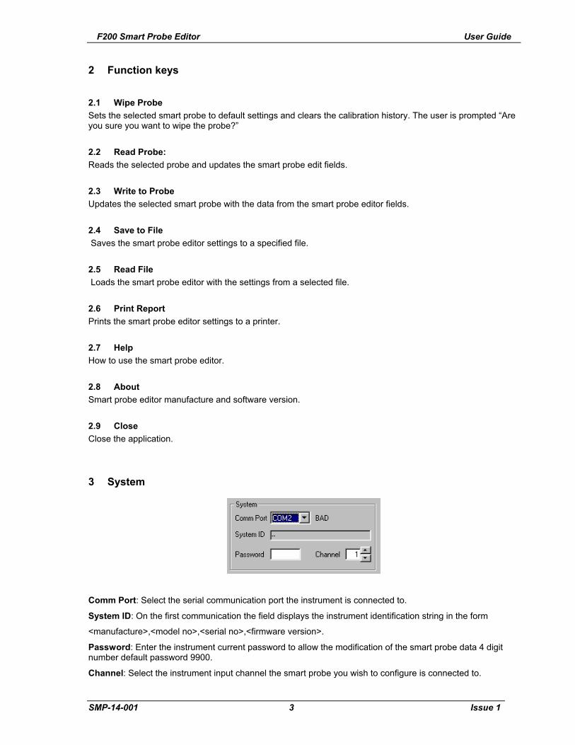
3 System
Comm Port: Select the serial communication port the instrument is connected to.
System ID: On the first communication the field displays the instrument identification string in the form
<manufacture>,<model no>,<serial no>,<firmware version>.
Password: Enter the instrument current password to allow the modification of the smart probe data 4 digit number default password 9900.
Channel: Select the instrument input channel the smart probe you wish to configure is connected to.
SMP-14-001 3 Issue 1

F200 Smart Probe Editor User Guide
4 Probe Control
Probe ID: Enter the serial number of the smart probe 20 characters maximum.
Format: Displays the smart probe data format. Always set to 1.
Lock: Each smart probe has a lock facility, if a smart probe Lock is set to 'Yes' the data in the smart probe can not be modified from the instrument.
5 Working Range
Min: Enter the minimum working range for the smart probe 0 to 400 ohms.
Max: Enter the maximum working range for the smart probe 0 to 400 ohms.
Min since last cal: Displays the minimum value the smart probe exceeded outside its working range since its last calibration, automatically reset each time the smart probe is written to.
Max since last cal: Displays the maximum value the smart probe exceeded outside its working range since its last calibration, automatically reset each time the smart probe is written to.
Min ever: Displays the minimum value the smart probe exceeded outside its working range during its working life, automatically reset each time the smart probe is wiped.
Max ever: Displays the maximum value the smart probe exceeded outside its working range during its working life, automatically reset each time the smart probe is wiped.
SMP-14-001 4 Issue 1

F200 Smart Probe Editor User Guide
6 Coefficients
Conversion type: Select the required resistance to temperature conversion method Din, CvD or ITS90.
Ap, Bp, Cp, Dp, R0.01, Wt, An, Bn
Conversion Temperature Range Required Coefficients
Din -200 C to 850 C R0, A, B, C.
CvD -200 C to 850 C R0, A, B, C.
ITS90 83.8058K to 273.16K R0.01, An, Bn.
ITS90 273.15K to 961.78 C R0.01, Ap, Bp, Cp, Dp, Wt.
ITS90 273.15K to 660.323 C R0.01, Ap, Bp, Cp.
ITS90 273.15K to 419.527 C R0.01, Ap, Bp.
ITS90 273.15K to 231.928 C R0.01, Ap, Bp.
ITS90 273.15K to 156.59865 C R0.01, Ap.
ITS90 273.15K to 29.7646 C R0.01, Ap.
ITS90 234.3156K to 29.7646 C R0.01, Ap, Bp.
SMP-14-001 5 Issue 1

F200 Smart Probe Editor User Guide
7 Calibration
Date: Enter the date the smart probe was calibrated DD/MM/YYYY.
The date is automatically set to the current PC date when the program is launched.
Next Date: Enter the date the smart probe next calibration date is due DD/MM/YYYY.
Source: Enter name of the company responsible for the smart probe calibration 20 characters maximum.
Calibration History: Displays the calibration history after reading the selected smart probe. Calibration history can only be cleared by the Wipe Probe function.
SMP-14-001 6 Issue 1
F200 Smart Probe Editor User Guide
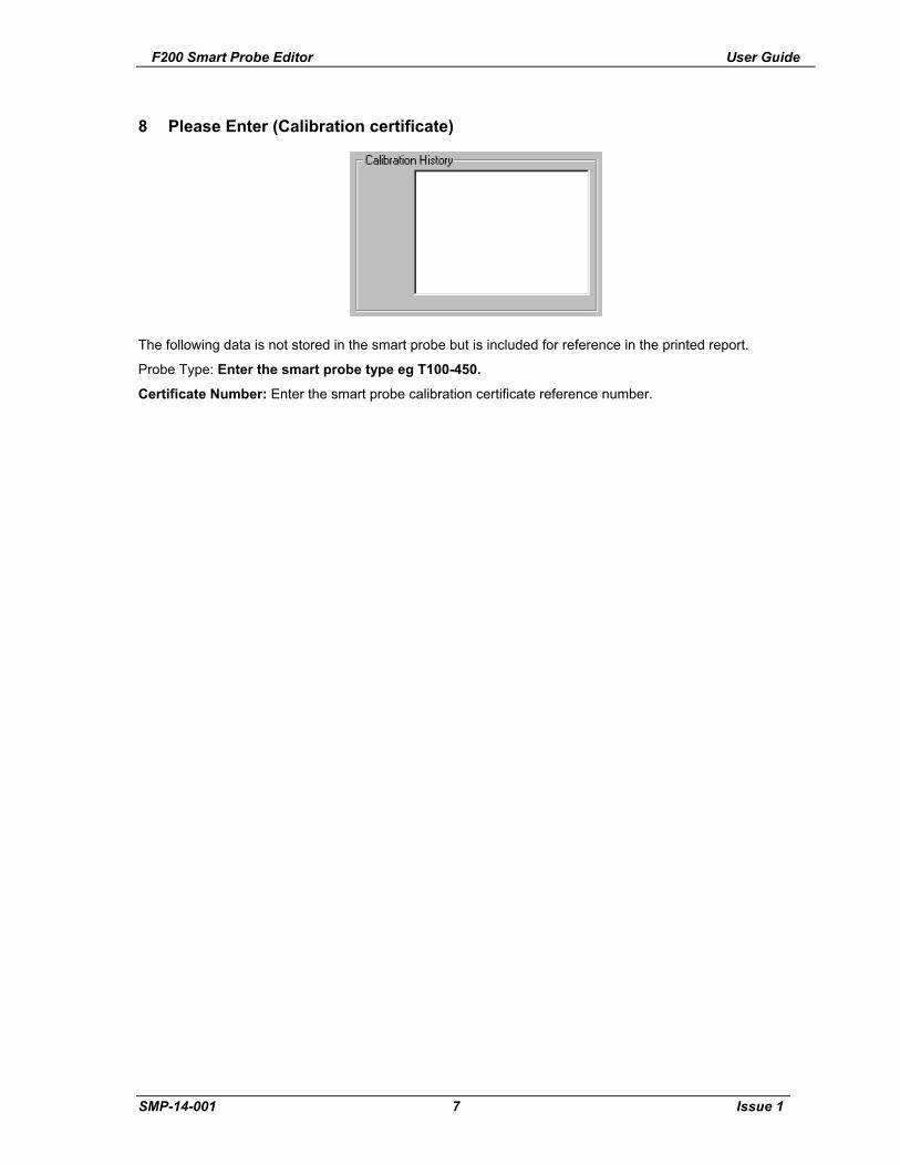
8 Please Enter (Calibration certificate)
The following data is not stored in the smart probe but is included for reference in the printed report.
Probe Type: Enter the smart probe type eg T100-450.
Certificate Number: Enter the smart probe calibration certificate reference number.
SMP-14-001 7 Issue 1

Table of Contents
1. INTRODUCTION....................................................................................................................................1-1
1.1 Overview ............................................................................................................................................1-1
1.2 Definitions and Terminology ..............................................................................................................1-1
1.3 Principles of measurement ................................................................................................................1-2
1.3.1 PRT measurement.........................................................................................................................1-2
2. SETTING UP THE F200 ........................................................................................................................2-1
2.1 Safety information ..............................................................................................................................2-1
2.2 Unpacking the instrument ..................................................................................................................2-1
3. ABOUT THE F200 .................................................................................................................................3-1
3.1 The Front Panel .................................................................................................................................3-1
3.2 About the display screen....................................................................................................................3-1
3.3 The Front Panel keypad.....................................................................................................................3-1
3.4 Thermometer inputs...........................................................................................................................3-3
3.5 Rear panel..........................................................................................................................................3-4
3.5.1 AC Power Input Socket..................................................................................................................3-4
3.5.2 Rating plate....................................................................................................................................3-4
3.5.3 Supply On/Off Switch.....................................................................................................................3-4
3.5.4 RS232 Communication interface connector..................................................................................3-4
3.5.5 Name plate ....................................................................................................................................3-4
4. OPERATING THE F200.........................................................................................................................4-1
4.1 Instrument operating mode ................................................................................................................4-1
4.1.1 Temperature Measurement Mode .......................................................................................4-1
4.1.2 Configuration Mode .......................................................................................................................4-2
4.1.3 Setting up Temperature measurement..........................................................................................4-3
4.1.4 Statistics.........................................................................................................................................4-5
4.1.5 Options...........................................................................................................................................4-5
4.1.6 Smart Probe review .......................................................................................................................4-6
4.1.7 Real Time Clock ............................................................................................................................4-7
4.1.8 Display Brightness.........................................................................................................................4-7
5. INSTRUMENT MEASUREMENT RANGE ............................................................................................5-1
5.1 Instrument measurement working range ...........................................................................................5-1
5.2 Open Circuit Probes...........................................................................................................................5-1
5.3 Measurement Range .........................................................................................................................5-1
6. SMART PROBES ..................................................................................................................................6-1
6.1 About Smart Probes...........................................................................................................................6-1
6.2 How Smart Probes Work ...................................................................................................................6-1
6.3 Smart Probe Data Security ................................................................................................................6-1
6.4 Smart Probe Calibration Supervisor ..................................................................................................6-1
6.5 Smart Probe Working Range Monitor................................................................................................6-1
6.6 Review Edit Data................................................................................................................................6-2
6.7 Smart Probe Data ..............................................................................................................................6-2
7. CALIBRATING THE F200 .....................................................................................................................7-1
F200-14-001 Page 1-1
ASL 2003

Contents
7.1 F200 Instrument calibration ...............................................................................................................7-1
7.1.1 Instrument Calibration Supervisor .................................................................................................7-1
7.2 Equipment ..........................................................................................................................................7-1
7.3 Calibration procedure.........................................................................................................................7-1
8. COMMUNICATIONS INTERFACE........................................................................................................8-1
8.1 Introduction ........................................................................................................................................8-1
8.2 Overview of the RS-232 Serial Interface ...........................................................................................8-1
8.2.1 The RS-232 Connector..................................................................................................................8-2
8.2.2 Pin Connections.............................................................................................................................8-2
8.3 RS-232 Settings .................................................................................................................................8-2
8.3.1 Talk only mode (Auto output) ........................................................................................................8-3
8.3.2 Remote mode (Local lockout)........................................................................................................8-3
8.3.3 Power up state...............................................................................................................................8-3
8.3.4 Communication protocol ................................................................................................................8-3
8.3.5 Programming command syntax.....................................................................................................8-3
8.3.6 Long form short form commands...................................................................................................8-4
8.3.7 Case sensitivity..............................................................................................................................8-4
8.3.8 Command Terminators (CR) or (CR)(LF)......................................................................................8-4
8.3.9 Input Buffer ....................................................................................................................................8-4
8.3.10 Output Data Format...................................................................................................................8-4
8.4 RS-232 Interface Commands ............................................................................................................8-5
8.4.1 SYSTem:REMote ..........................................................................................................................8-5
8.4.2 SYSTem:LOCal .............................................................................................................................8-5
8.4.3 *IDN? .............................................................................................................................................8-5
8.4.4 CAL:DATE <year>,<month>,<day>...............................................................................................8-6
8.4.5 CAL:DATE? ...................................................................................................................................8-6
8.4.6 CAL:NEXTDATE <year>,<month>,<day>.....................................................................................8-6
8.4.7 CAL:NEXTDATE?..........................................................................................................................8-6
8.4.8 System Command Summary.........................................................................................................8-7
8.5 Measurement Command Group ........................................................................................................8-8
8.5.1 CONFigure:CHANnel <channel>...................................................................................................8-8
8.5.2 CONFigure?...................................................................................................................................8-8
8.5.3 FETch? ..........................................................................................................................................8-8
8.5.4 READ?...........................................................................................................................................8-9
8.5.5 MEASure Command......................................................................................................................8-9
8.5.6 MEASure:CHANnel? <channel> ...................................................................................................8-9
8.6 UNIT Command Group ....................................................................................................................8-10
8.6.1 UNIT:TEMPerature <units> .........................................................................................................8-10
8.6.2 UNIT:TEMPerature? ....................................................................................................................8-10
8.7 Trigger Command Group .................................................................................................................8-11
8.7.1 INITiate ........................................................................................................................................8-11
8.7.2 ABORt..........................................................................................................................................8-11
8.7.3 TRIGger:MODE <mode>.............................................................................................................8-11
8.8 System Related Commands ............................................................................................................8-12
8.8.1 SYSTem:PASSword:DEFAult......................................................................................................8-12
8.8.2 SYSTem:PASSword:CENable <password>................................................................................8-12
8.8.3 SYSTem:PASSword:CDISable <password>...............................................................................8-12
8.8.4 SYSTem:PASSword:CENable:STATe? ......................................................................................8-12
8.8.5 SYSTem:PASSword:NEW <current password>,<new password>.............................................8-13
Page 1-2 F200-14-001
ASL 2003

Introduction
8.8.6 SYSTem:BEEPer:IMMediate.......................................................................................................8-13
8.8.7 SYSTem:TIME <hour>,<minute>,<second> ...............................................................................8-13
8.8.8 SYSTem:TIME?...........................................................................................................................8-13
8.8.9 SYSTem:DATE <year>, <month>, <day> ...................................................................................8-14
8.8.10 SYSTem:DATE?......................................................................................................................8-14
8.9 SENSe Command Group.................................................................................................................8-15
8.9.1 SENSe:ZERO:AUTO <mode>.....................................................................................................8-15
8.9.2 SENSe:ZERO:AUTO?.................................................................................................................8-15
8.9.3 SENSe:FRTD:CAL:DATE <year>,<month>,<day>.....................................................................8-15
8.9.4 SENSe:FRTD:CAL:DATE?..........................................................................................................8-16
8.9.5 SENSe:FRTD:CAL:NEXT <year>,<month>,<day>.....................................................................8-16
8.9.6 SENSe:FRTD:CAL:NEXT?..........................................................................................................8-16
8.9.7 SENSe:FRTD:CAL:HISTory? ......................................................................................................8-17
8.9.8 SENSe:FRTD:CAL:SOURce <source>.......................................................................................8-17
8.9.9 SENSe:FRTD:CAL:SOURce? .....................................................................................................8-17
8.9.10 SENSe:FRTD:FORMat <format>............................................................................................8-17
8.9.11 SENSe:FRTD:FORMat? .........................................................................................................8-18
8.9.12 SENSe:FRTD:STANdard <standard>.....................................................................................8-18
8.9.13 SENSe:FRTD:STANdard? ......................................................................................................8-18
8.9.14 SENSe:FRTD:COEFficient <coefficient>,<value> ..................................................................8-19
8.9.15 SENSe:FRTD:COEFficient? <coefficient>..............................................................................8-19
8.9.16 SENSe:FRTD:IDENtification <identification>..........................................................................8-19
8.9.17 SENSe:FRTD:IDENtification? .................................................................................................8-20
8.9.18 SENSe:FRTD:RANGe <rmax>,<rmin> ...................................................................................8-20
8.9.19 SENSe:FRTD:RANGe?...........................................................................................................8-20
8.9.20 SENSe:FRTD:LOCK ...............................................................................................................8-21
8.9.21 SENSe:FRTD:LOCK? .............................................................................................................8-21
8.9.22 Command summary ................................................................................................................8-21
9. OPTIONS AND ACCESSORIES ...........................................................................................................9-1
9.1 Accessories........................................................................................................................................9-1
10. SPECIFICATION .............................................................................................................................10-1
10.1 Resistance thermometer measurement...........................................................................................10-1
10.2 Display .............................................................................................................................................10-1
10.3 Supply ..............................................................................................................................................10-1
10.4 Environmental ..................................................................................................................................10-2
10.5 Dimensions ......................................................................................................................................10-2
10.6 Pt 100 System Accuracy..................................................................................................................10-2
11. CLEANING AND MAINTENANCE..................................................................................................11-1
11.1 Cleaning ...........................................................................................................................................11-1
11.2 Preventive Maintenance ..................................................................................................................11-1
11.3 General Safety Warning...................................................................................................................11-1
12. SERVICE AND WARRANTY ..........................................................................................................12-1
12.1 Technical Support ............................................................................................................................12-1
12.2 Returned Instruments ......................................................................................................................12-1
F200-14-001 Page 1-3
ASL 2003

Contents
This page is intentionally left blank.
Page 1-4 F200-14-001
ASL 2003

1. Introduction
1.1 Overview
The F200 Precision Thermometer is a high accuracy instrument designed for laboratory and industrial
temperature measurement and calibration applications.
Features include:
!" The number of input channel can be expanded from two to eight channels;
!" A large graphic VFD display for excellent viewing of temperature measurement values and
configuration settings;
!" Galvanically isolated RS232C communication interface (4KV isolation) as standard for
automated monitoring and calibration applications;
!" Self calibration against a traceable external standard;
The F200 will operate with all 4-wire Pt100 (100 Ohm) platinum resistance thermometers.
Temperature measurement units are selectable by single front panel key operation;"
"#C, #F, K & $%
Resistance accuracy is better than &4m$' (over full range at +20°C ±2°C) equivalent to temperature
measurement precision of &10mK for Pt100 thermometers. Total system measurement uncertainties
as low as &15mK are possible when the F200 is used with a calibrated reference thermometer.
Overall system accuracy depends on the PRT quality and calibration.
1.2 Definitions and Terminology
i. 0°C = 273.15 K
ii. 1 mK (milli-Kelvin) = 0.001#C (one milli-degree Celsius)
iii. 1 milli-degree C = 0.001#C = 1m#C = 1mK = 1.8m#F
iv. 1 milli-degree F = 0.001#F = 1m#F = 0.56mK = 0.56m#C
v. Alpha, or (, is the temperature coefficient, or temperature sensitivity, of the platinum wire
used in PRTs. In general, the greater the alpha value, the better the PRT thermometer
measurement reproducibility, stability and performance.
vi. Abbreviations for platinum resistance thermometers include:
PRT (Platinum Resistance Thermometer)
Pt100 (PRT with nominally 100$ resistance at 0#C)
RTD (Resistance Temperature Device)
vii. System accuracy refers to the overall, combined accuracy of the F200 and thermometer.
F200-14-001 Page 1-1
ASL 2003

Introduction
General warning symbol. This indicates that a
hazardous condition or general danger may exist. You
must read the relevant sections in the Operator’s
Handbook before operating the instrument.
1.3 Principles of measurement
1.3.1 PRT measurement
The F200 measures the voltage (Vt) developed across the unknown sensor resistance (Rt) and the
voltage (Vs) across a stable internal reference resistance (Rs). The voltages are in proportion to the
resistances so the thermometer resistance is derived from:
Rt = Rs x Vt / Vs
This technique achieves immunity from slow moving time and temperature drift in the electronics, as it
is not affected by voltage measurement gain variations or current source fluctuations.
In the same way that AC resistance measurement eliminates thermal EMFs, switched DC achieves a
similar advantage. Switched DC works by reversing the current flow on alternate measurement cycles
and taking the average value, thereby cancelling any thermal EMF offsets from the measurement.
For PRTs, the relationship between resistance and temperature varies slightly from one PRT to
another. Therefore, no matter how accurately the F200 measures the PRT resistance, if the
relationship between resistance and temperature for a particular PRT is not known, accurate
temperature measurement is not possible.
The F200 uses PRT calibration data to overcome this problem and calculates temperature from
temperature conversion functions stored in either the PRT’s ‘SMART’ connector or the instruments
internal memory. This method enables the F200 accurately to convert resistance to temperature,
uniquely for each PRT used. It is very important therefore that a PRT without ‘SMART’ connector is
used on the correct and properly configured input channel.
The system accuracy is a combination of the F200 accuracy in measuring PRT resistance and the
calibration uncertainty placed on the PRTs by the calibrating laboratory. Using the F200 with PRT
type T100-250-1, this is &0.025#C for temperatures from -50#C to +250#C.
Page 1-2 F200-14-001
ASL 2003

2. Setting up the F200
2.1 Safety information
!" Please read the safety information sheet before operating the F200.
2.2 Unpacking the instrument
When you unpack the F200 thermometer, check that the following items are present before starting to
use the unit:
!" 1x F200 precision thermometer
!" 1x AC power cord
!" 1x Quick-start guide
!" 1x Operator’s handbook on CD
!" 1x Calibration certificate
Please contact the ASL Technical Services Group immediately if any of these items are missing or
damaged.
F200-14-001 Page 2-1
ASL 2003

Setting up the F200
This page is intentionally left blank.
Page 2-2 F200-14-001
ASL 2003

3. About the F200
This section introduces you to the features and functions of the F200 Precision Thermometer.
3.1 The Front Panel
VFD Display
Front panel buttons
Function keys
Figure 3.1- Front Panel
3.2 About the display screen
The large graphic VFD display screen is your direct link to the instrument, presenting you with
information or menus that prompt you on what to do next.
3.3 The Front Panel keypad
The instrument keypad consists of five Function keys and three Menu keys.
In Temperature Measurement Mode the function keys are use to directly control the measurement
operation of the instrument.
F200-14-001 Page 3-1
ASL 2003

Setting up the F200
In Instrument Configuration Mode the function keys operate as soft keys along with the menu keys
to enable the operator to configure the instrument
For a detailed description of how to use the keys to configure and operate the instrument, refer to
Section 5.
Table 3.1 Summary of front panel key functions
Key symbol Description Function
Selecting Input Channels
Ch Select input channel 1 to 8
Selects and displays measurement channel 1 to 8
A-B Select differential measurement
ChA ) ChB
Relative measurement function displays the difference between selected ChA and ChB inputs
Setting up Measurement Options
ZERO Measurement display zero function
Nulls the display at the current reading and displays measured values relative to the nulled value.
HOLD Measurement run/ hold
Display hold, trigger continuous measurement or hold.
UNIT Measurement units
Selects measurement display units: °C, °F,
K, $
Menu Functions
MENU Select Menu options
Cycles through the main menu functions of the instrument.
CLEAR Clear data entry Clears any data entry errors or min/max statistics
ENTER Save entry Saves data entry and returns to previous menu.
Page 3-2 F200-14-001
ASL 2003

Setting up the F200
3.4 Thermometer inputs
The thermometer-input 5 pin DIN sockets are located on the top panel for ease of use. The number of
input channels can easily be expanded from two to eight channels. When the instrument is turned on,
it automatically detects the number of input channels.
Each input channel can accept either a Smart probe or a Passive probe; any combination of probes
can be use together.
The selected input channel is interrogated before each measurement cycle, smart probes are
identified by ‘s’ on the bottom left hand corner of the display, passive probes are identified by a dot ‘.’.
Open circuit thermometer input channels will be reported as ‘No Probe’.
Pt100
1I+
V+
Shield
I-
V-
2
3
4
5 PRT CONNECTION - 4 WIRE(5-pin DIN connector)viewed from top panel
Figure 3.4.1 4-Wire Passive PRT input connection configuration
Pt100
1I+
V+
Shield
I-
V-
2
3
4
5 PRT CONNECTION - 4 WIRE(5-pin DIN connector)viewed from top panel
SMP
Figure 3.4.2 4-Wire SMART Probe PRT input connection configuration
F200-14-001 Page 3-3
ASL 2003

Setting up the F200
3.5 Rear panel
Figure 3.5 - Rear Panel layout, showing all options
3.5.1 AC Power Input Socket
The instrument is fitted with a universal input power supply unit; the AC power input socket accepts 3-
pin IEC320 AC type power connector.
The instrument is protected by an internal T1 amp Anti surge surface mount fuse (case size 1206)
located in a fuse carrier on the front right of the main PCB.
The power lead supplied with the instrument contains a separate ground lead, this ground lead
provides the instrument safety ground, to maintain this safety the instrument must be grounded.
3.5.2 Rating plate
Instrument rating plate, contains the AC voltage range, operating supply frequency range, the
instrument maximum power consumption and instrument serial number.
3.5.3 Supply On/Off Switch
The supply switch is used to switch the instrument On or Off.
Switching the supply Off does not is isolate the instrument, to isolate the instrument make sure the
instrument is disconnected from the AC line and any other equipment.
3.5.4 RS232 Communication interface connector
RS232 communication via a 9 way D type plug is fitted as standard.
3.5.5 Name plate
Instrument nameplate, contains the manufacture name and address details.
Page 3-4 F200-14-001
ASL 2003
4. Operating the F200
4.1 Instrument operating mode
The instrument has two operating modes:
!" the Temperature Measurement Mode which displays channel status information and a
sequence of measurement readings;
!" the Configuration Mode which lets you set up and configure the instrument.
4.1.1 Temperature Measurement Mode
In temperature measurement mode the instrument function is controlled directly from the five function
keys.
4.1.1.1 Selecting thermometer input channel
Press the ‘Ch’ channel key to select the required input channel, the current selected channel number
is displayed on the main display.
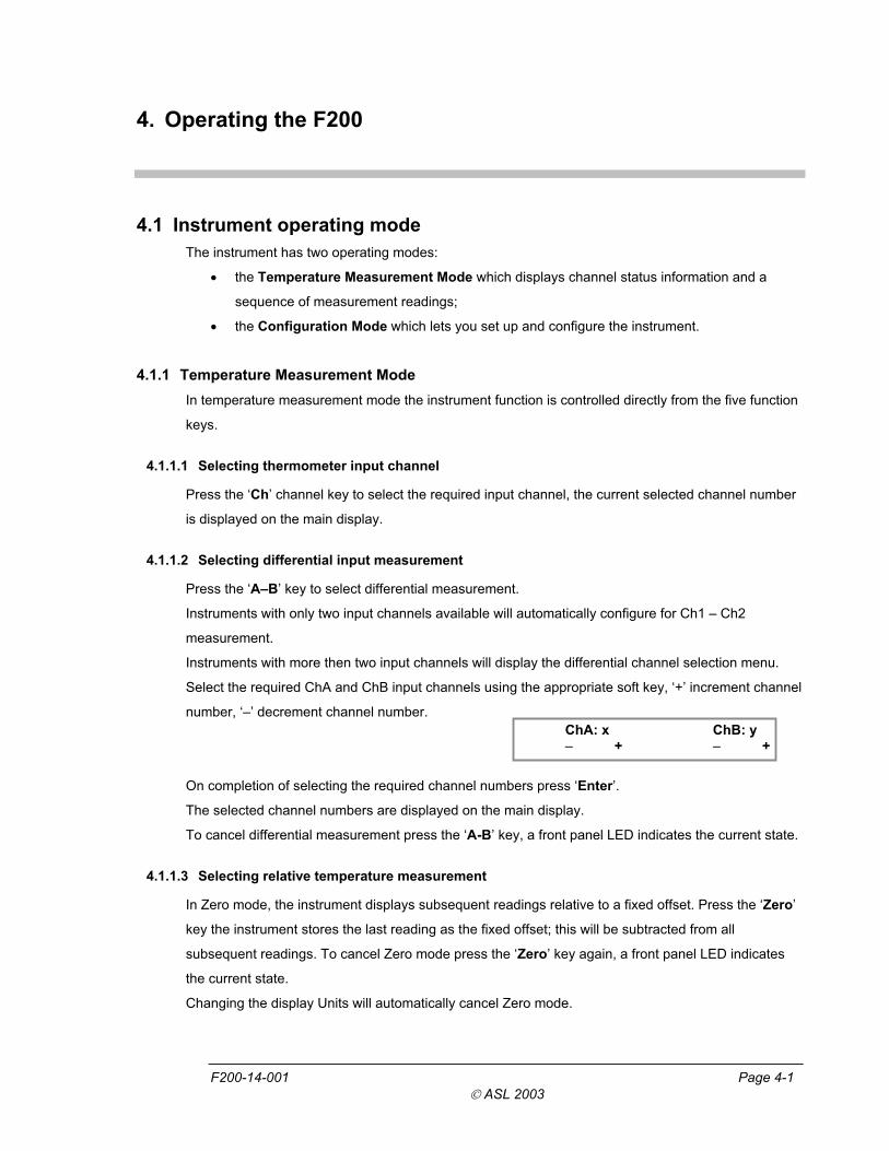
4.1.1.2 Selecting differential input measurement
Press the ‘A–B’ key to select differential measurement.
Instruments with only two input channels available will automatically configure for Ch1 – Ch2
measurement.
Instruments with more then two input channels will display the differential channel selection menu.
Select the required ChA and ChB input channels using the appropriate soft key, ‘+’ increment channel
number, ‘–’ decrement channel number.
ChA: x ChB: y – + – +
On completion of selecting the required channel numbers press ‘Enter’.
The selected channel numbers are displayed on the main display.
To cancel differential measurement press the ‘A-B’ key, a front panel LED indicates the current state.
4.1.1.3 Selecting relative temperature measurement
In Zero mode, the instrument displays subsequent readings relative to a fixed offset. Press the ‘Zero’
key the instrument stores the last reading as the fixed offset; this will be subtracted from all
subsequent readings. To cancel Zero mode press the ‘Zero’ key again, a front panel LED indicates
the current state.
Changing the display Units will automatically cancel Zero mode.
F200-14-001 Page 4-1
ASL 2003

Operating the F200
4.1.1.4 Selecting run/hold mode
In Hold mode the instrument measurement cycle is stopped.
Press the ‘Hold’ key to alternate between Run and Hold mode; a front panel LED indicates the
current state.
4.1.1.5 Selecting Units
Press the ‘Unit’ key to select the required measurement units, Resistance ($), Celsius (°C),
Fahrenheit (°F) or Kelvin (K), the current selected units are displayed on the main display.
Changing the Units will automatically clear the maximum and minimum recorded values in statistics.
4.1.2 Configuration Mode
In configuration mode the instrument function is controlled from the three menu keys and the five
function keys now operating as soft keys. The function of a soft key is indicated on the VFD display
directly above the key.
To enter the instrument configuration mode press the ‘Menu’ key.
The instrument menu structure for ease of use is arranged as a series of top-level menu’s leading to a
series of sub menu’s. To cycle through the top level menus repeatedly press the ‘Menu’ key. To
select the required sub menu, press the appropriate soft key. To exit a sub menu and return to
temperature measurement mode press the ‘Menu’ key.
4.1.2.1 Top level menu
Chx PRT Din Review Edit
Channel configuration menu, review or edit the channel
temperature conversion algorithm and coefficients.
Statistics menu, review or clear maximum and
minimum recorded values. Statistics Min Max
Options Cal Com Ver
Options menu, calibrate the instrument, set talk only
mode or review the instrument firmware issue.
Smart Probe Review
Smart Probe review menu (menu only available if
smart probe detected).
Real Time Clock Date Time
Real Time Clock menu set the real time clock date
and time.
Brightness - +
Brightness menu set the display brightness.
Page 4-2 F200-14-001
ASL 2003
Operating the F200
4.1.3 Setting up Temperature measurement
To enable accurate resistance to temperature conversion to be carried out by the instrument the PRT
characterisation data is required
o temperature conversion algorithm
o temperature conversion algorithm coefficients
The data can be stored in either a smart probe or the instrument internal none-volatile memory, each
thermometer input channel store one set of PRT characterisation data.
4.1.3.1 Temperature measurement with smart probe (s)
If a smart probe is detected on a selected input channel the PRT data is loaded direct from the smart
probe. Smart probe data always takes preference over the instrument channel data but does not over
write the instrument channel data, no other set up is required.
4.1.3.2 Temperature measurement with passive probes (.)
The instrument can store one set of PRT characterisation data for each thermometer input channel.
4.1.3.3 Temperature conversion algorithm
The instrument provides three standard algorithms for converting resistance to temperature. The
choice will depend on the type of PRT and its calibration.
!" Din (1992):- used for un-calibrated industrial PRTs with 0.00385 ‘alpha’ value, to provide a
conversion of resistance to temperature in accordance with BS EN60751 (ITS 90) standard.
!" CvD coefficients:- Callendar Van Dusen used for calibrated industrial or low alpha PRT’s of
0.00385.
!" ITS90 coefficients:- used for calibrated high alpha PRT’s of values 0.003926 to 0.003928.
4.1.3.4 Review Temperature conversion algorithm
Chx PRT Din
Review Edit
Select the required input channel using the ‘Ch’ key.
Select the channel set up menu using the ‘Menu’ key.
The channel number and temperature conversion method are displayed on the first line of the menu.
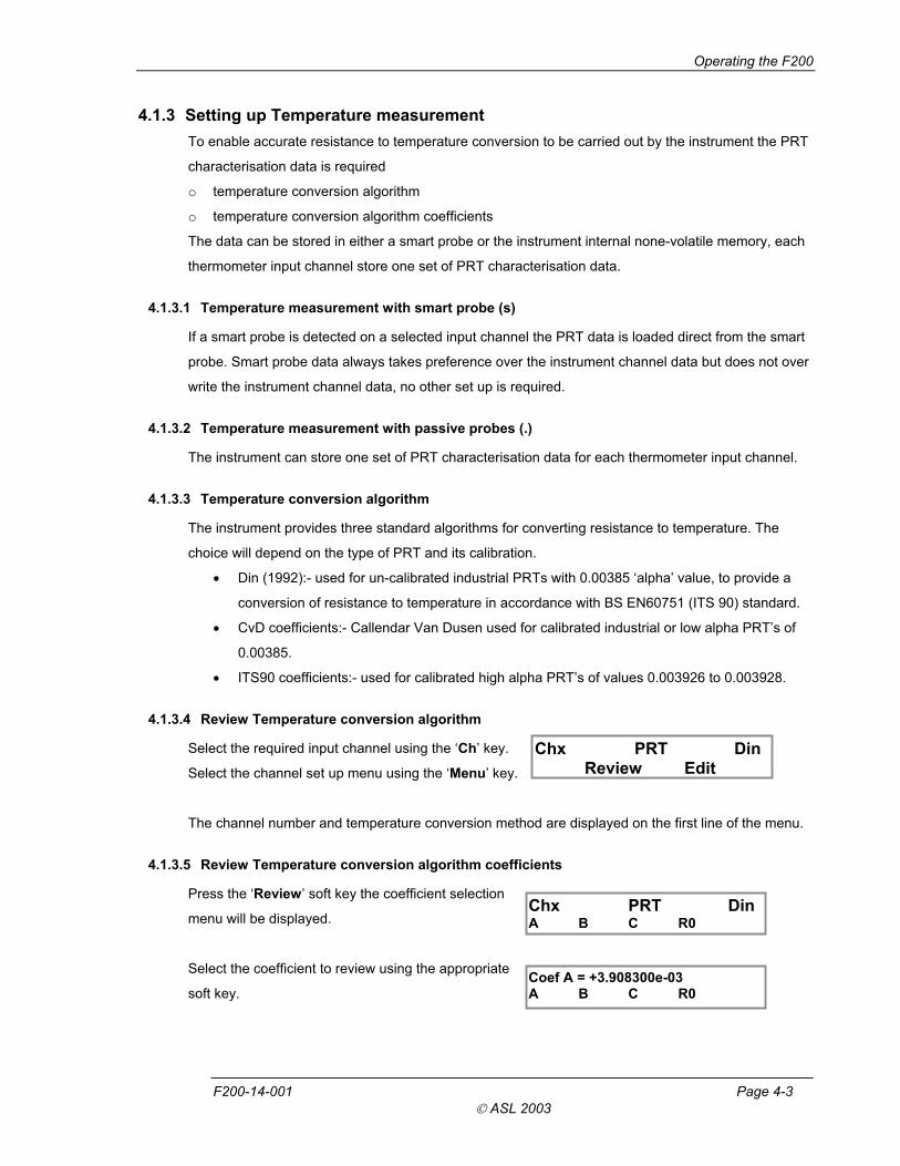
4.1.3.5 Review Temperature conversion algorithm coefficients
Press the ‘Review’ soft key the coefficient selection
menu will be displayed. Chx PRT Din
A B C R0
Select the coefficient to review using the appropriate
soft key. Coef A = +3.908300e-03 A B C R0
F200-14-001 Page 4-3
ASL 2003

Operating the F200
To review the next coefficient press the appropriate soft key.
Select ‘<’ or ‘>’ soft key to scroll between pages (Its90 coefficients only).
Press ‘Menu’ key to exit configuration mode and return to measurement mode.
4.1.3.6 Edit temperature conversion algorithm and coefficients
Select ‘Edit’ from the channel set up using the appropriate
soft key.
Password 0000 < - + >
The password enter menu will be displayed.
Press the ‘<’ or ‘>’ soft key to move the flashing cursor to the required digit.
Press the ‘ ’ or ‘+’ soft key to decrement or increment the flashing digit.
Press the ‘Enter’ key to enter the password (Default password 9900).
Press the ‘Menu’ key to exit configuration mode and return to measurement mode.
On exit from the coefficient edit menu the password protection is reset.
On entering the correct password the resistance to
temperature option menu will be displayed.
Chx PRT Din Din ITS90 CvD
Select the temperature conversion method using the
appropriate soft key, the coefficient selection edit menu
will be displayed.
Chx PRT Din A B C R0
Select the required coefficient to edit using the appropriate
soft key; the coefficient edit menu will be displayed.
Coef A = +3.908300e-03 < - + >
Press the ‘<’ or ‘>’ soft key to move the flashing cursor to the required digit.
Press the ‘ ’ or ‘+’ soft key to decrement or increment the flashing digit.
Press the ‘Enter’ key to select the next coefficient to edit.
Save changes Yes No
Press the ‘Menu’ key, the save changes option menu
will be displayed.
Press the ‘Yes’ soft key to save changes to memory.
Press the ‘No’ soft key to discard the changes.
If a smart probe is detected the changes will be saved in the smart probe, if a passive probe is
detected the changes will be saved into the instrument channel configuration.
The select another channel options menu will be displayed. Another Channel? Yes No
Page 4-4 F200-14-001
ASL 2003

Operating the F200
Press the ‘Yes’ soft key the channel selection menu will be displayed.
Chan 1 < - + >
Press the ‘No’ soft key to exit configuration mode and
return to measurement mode.
Press the ‘ ’ or ‘+’ soft key to decrement or increment the channel number.
Press the ‘Enter’ key to select the input channel and return to the channel set up menu.
4.1.4 Statistics
The instrument automatically records maximum and minimum readings during its operating period.
Statistics Min Max
Select the Statistics menu using the ‘Menu’ key.
Press the ‘Min’ soft key to display the current minimum value.
Press the ‘Max’ soft key to display the current maximum value.
Press the ‘Clear’ key to clear the current statistical values.
Press the ‘Menu’ key to exit configuration mode and return to measurement mode.
The statistical values are also cleared when the units are changed and at power on.
4.1.5 Options
From the Options menu you can select to calibrate the instrument, set the RS232 communication talk
only mode or review the model number, firmware version and instrument serial number.
Options Cal Com Ver
Select the Options menu using the ‘Menu’ key.
4.1.5.1 Calibrate the instrument
Refer to Section 6 to calibrate the instrument.
4.1.5.2 Talk only mode
In Talk only mode the instrument ignores all received serial communication commands, on completion
of each measurement cycle the channel number, measurement value and units are automatically
output over the RS232 serial communication port.
Talk only Off On Off
Select the ‘Com’ soft key; the Talk only selection
menu is displayed.
Press the ‘On’ soft key to set RS232 serial communication Talk only mode on.
Press the ‘Off’ soft key to set RS232 serial communication Talk only mode off.
Press the ‘Menu’ key to exit configuration mode and return to measurement mode.
F200-14-001 Page 4-5
ASL 2003

Operating the F200
4.1.5.3 Firmware Version
Select the ‘Ver’ soft key, the instrument firmware version,
firmware date and instrument serial number are displayed.
V1.1C 6August03 Serial No 1005
Press the ‘Menu’ key to exit configuration mode and return to measurement mode.
Smart Probe review menu option is not available in A-B measurement mode.
4.1.6 Smart Probe review
Smart Probe Review
The smart probe review menu allows the user to quickly
view the smart probe data.
Select the smart probe review menu using the ‘Menu’ key.
Press the ‘Review’ soft key to enter the smart probe
review menu. Version = 1 lock = 0 Cal type : Din
Press the ‘Enter’ key repeatedly to step through the
data review pages.
Version Smart probe data format.
Lock Password protection state.
0 = smart probe data locked can not be changed from the instrument.
1 = smart probe data unlocked can be changed from the instrument.
Cal type Selected method of resistance to temperature conversion algorithm to use, Din,
ITS90 or CvD.
The temperature conversion coefficients can be
reviewed from the channel set up menu.
Cal date: dd-mm-yyyy Due date: dd-mm-yyyy
Cal date Date of the smart probe calibration. Source: ASL Due date Date the smart probe calibration is
next due.
Source Company whom carried out the smart
probe calibration. Serial Number: ASL123456
Max since cal: Min since cal: Serial Number Serial number of the smart probe.
Max since cal Maximum recorded temperature the smart probe has been exposed to since it was
last calibrated (units are in resistance).
Min since cal Minimum recorded temperature the smart probe has been exposed to since it was
last calibrated (units are in resistance).
Page 4-6 F200-14-001
ASL 2003

Operating the F200
Max ever Maximum recorded temperature the smart
probe has been exposed to during its
working life (units are in resistance).
Max ever: Min ever:
Min ever Minimum recorded temperature the smart probe has been exposed to during its
working life (units are in resistance).
Press the ‘Menu’ key at any point to exit configuration mode and return to measurement mode.
4.1.7 Real Time Clock
The instrument maintains the date and time from its internal real time clock.
Select the Real Time Clock menu using the ‘Menu’ key. Real Time Clock Date Time
4.1.7.1 Date Setting
Date = dd/mm/yy < - + > Select the ‘Date’ soft key, the date edit menu showing
the current date will be displayed.
Press the ‘<’ or ‘>’ soft key to move the flashing cursor to the required digit.
Press the ‘ ’ or ‘+’ soft key to decrement or increment the flashing digit.
Press the ‘Enter’ key to save the new date and return to the real time clock menu.
Press the ‘Menu’ key to exit configuration mode and return to measurement mode.
4.1.7.2 Time Setting
Time = hh/mm/ss < - + >
Select the ‘Time’ soft key, the time edit menu showing
the current time will be displayed.
Press the ‘<’ or ‘>’ soft key to move the flashing cursor to the required digit.
Press the ‘ ’ or ‘+’ soft key to decrement or increment the flashing digit.
Press the ‘Enter’ key to save the new time and return to the real time clock menu.
Press the ‘Menu’ key to exit configuration mode and return to measurement mode.
4.1.8 Display Brightness
The intensity of the vacuum fluorescent display can be adjusted to suit the working environment. The
pre-set level is stored in non-volatile memory and recalled at power on.
Select the Brightness menu using the ‘Menu’ key. Brightness - +
Press the ‘ - ‘ soft key to decrease the display brightness.
Press the ‘+’ soft key to increase the display brightness.
Press the ‘Menu’ key to exit configuration mode and return to measurement mode.
F200-14-001 Page 4-7
ASL 2003

Operating the F200
This page is intentionally left blank.
Page 4-8 F200-14-001
ASL 2003

5. Instrument Measurement Range
5.1 Instrument measurement working range
The instrument measurement circuit can detect the following conditions Open Circuit Probe, Over
Range measurement and Under Range measurement.
5.2 Open Circuit Probes
Open circuit input channels and open circuit probes are reported as No Probe on the display and over
the communication interface.
Over Range measurements are reported as O_Range on the display and over the communication
interface.
Under Range measurements are reported as U_Range on the display and over the communication
interface.
5.3 Measurement Range
Measurement Units Conversion Under Range Over Range Units
Resistance None 0 410 ohms
Din90 -201 +851 C
CvD -201 +850 C Temperature
ITS90 -201 +963 C
F200-14-001 Page 5-1
ASL 2003

Smart Probes
This page is intentionally left blank.
Page 5-2 F200-14-001
ASL 2003

6. Smart Probes
6.1 About Smart Probes
Smart probes are like passive probes except for one key advantage, all the probe details, calibration
data and probe history are stored within the probe and not within the measurement instrument.
Smart probes can freely be moved from channel to channel or instrument to instrument without the
need to manually enter any data into the measurement instrument.
6.2 How Smart Probes Work
Each smart probe if fitted with a small none volatile memory device, this device is transparent during
temperature measurements.
Before each measurement cycle the probe is interrogated, if a smart probe is detected an ‘s’ is
displayed in the bottom left hand corner of the display. The probe data is read into the measurement
instrument for use in the measurement process.
6.3 Smart Probe Data Security
To maintain a high level of data security the smart probe has a built in data Lock. If the data lock is
set, the smart probe data cannot be modified.
The state of the data Lock can only be changed from a PC via the F200 serial communication port
using ASL Smart Probe Edit software or a standard PC serial communication terminal program.
Lock = 0 Probe unlocked data can be modified.
Lock = 1 Probe locked data cannot be modified.
6.4 Smart Probe Calibration Supervisor
To assist in maintain a valid calibration the instrument checks the smart probe next calibration date
and compares it with the instruments current date. If the smart probe date is found to have expired
the instrument will warn the operator ‘Probe is out of calibration’.
6.5 Smart Probe Working Range Monitor
The smart probe working range monitor is used to monitor if a smart probe is used outside its
specified working range.
On completion of each measurement, the new reading is compared with the probe working range. If
the new reading is found to be outside the probe working range, the appropriate data fields are
updated.
F200-14-001 Page 6-1
ASL 2003

Smart Probes
6.6 Review Edit Data
The smart probe data can be reviewed or edited in a number of ways
o Review the data from the F200 Smart Probe menu refer to section 4.1.6.
o Review or edit the temperature conversion method and coefficients from the F200 channel
set up menu, refer to section 4.1.3.
o Review or edit the data from a PC via the F200 serial communication port using the ASL
Smart Probe Edit software.
o Review or edit the data from a PC via the F200 serial communication port using a standard
PC serial communication terminal program refer to section 8.
6.7 Smart Probe Data
Lock
Store the smart probe data Lock State, maintain a high level of data security.
Format
SENSe:FRTD:FORmat
Store the smart probe data format, for use in maintaining future compatibility.
Probe ID
SENSe:FRTD:IDENtification
Store the smart probe identification number, 20 characters maximum.
Conversion Standard
SENSe:FRTD:STANdard
Store the required resistance to temperature conversion method, Din, CvD or ITS90.
Coefficient Ap, Bp, Cp, Dp, R0.01, Wt, An, Bn
SENSe:FRTD:COEFficient
Store the required coefficient for use in resistance to temperature conversion.
Conversion Temperature Range Required Coefficients
Din -200#C to 850#C R0, A, B, C.
CvD -200#C to 850#C R0, A, B, C.
ITS90 83.8058K to 273.16K R0.01, An, Bn.
ITS90 273.15K to 961.78#C R0.01, Ap, Bp, Cp, Dp, Wt.
ITS90 273.15K to 660.323#C R0.01, Ap, Bp, Cp.
ITS90 273.15K to 419.527#C R0.01, Ap, Bp.
ITS90 273.15K to 231.928#C R0.01, Ap, Bp.
ITS90 273.15K to 156.59865#C R0.01, Ap.
ITS90 273.15K to 29.7646#C R0.01, Ap.
ITS90 234.3156K to 29.7646#C R0.01, Ap, Bp.
Page 6-2 F200-14-001
ASL 2003
Smart Probes
Min working range
SENSe:FRTD:RANGe
Store the smart probe working range minimum value, range 0 to 400 ohms.
Max working range
SENSe:FRTD:RANGe
Store the smart probe working range maximum value, range 0 to 400 ohms.
Min since last cal
Record the minimum value the smart probe exceeded outside its working range since it was last
calibrated, automatically reset when the smart probe is wiped.
Max since last cal
Record the maximum value the smart probe exceeded outside its working range since it was last
calibrated, automatically reset when the smart probe is wiped.
Min ever
Record the minimum value the smart probe exceeded outside its working range during its working life,
automatically reset when the smart probe is wiped.
Max ever
Record the maximum value the smart probe exceeded outside its working range during its working
life, automatically reset when the smart probe is wiped.
Date
SENSe:FRTD:CAL:DATE
Store the date the smart probe was calibrated DD/MM/YYYY.
Next Date
SENSe:FRTD:CAL:NEXT
Store the date the smart probe next calibration is due DD/MM/YYYY.
Source
SENSe:FRTD:CAL:SOURce
Store name of the company responsible for the smart probe calibration 20 characters maximum.
Calibration History
SENSe:FRTD:CAL:HISTory?
Maintain the calibration history of the smart probe. The calibration history is automatically updated
when the next calibration date is updated. The calibration history is cleared when the probe is wiped.
F200-14-001 Page 6-3
ASL 2003

Smart Probes
This page is intentionally left blank.
Page 6-4 F200-14-001
ASL 2003

7. Calibrating the F200
7.1 F200 Instrument calibration
The dc bridge measurement technique used in the F200 is inherently very stable and linear, better
than & 4 m$ over the full range at +20°C ±2°C (equivalent to & 10 mK with a Pt100 PRT). However
drift of the internal reference resistor will occur with time making periodic re-calibration necessary.
7.1.1 Instrument Calibration Supervisor
To assist in maintain a valid calibration, at power on the instrument next calibration date is compared
with the instrument current date. If the next calibration date is found to have expired the instrument
will warn the operator. Instrument out Of Calibration
Press the ‘No’ soft key to continue if you do not
wish to calibrate the instrument. Calibration Now? Yes No Press the ‘Yes’ soft key to enter the instrument
calibration menu, the password enter menu will
be displayed.
7.2 Equipment
Temperature controlled environment at +20°C ±2°C
Calibrated 400 ohm +/- 10 ohm reference resistor at +/- 1 ppm accuracy.
7.3 Calibration procedure
Place the instrument to be calibrated in a +20°C ±2°C temperature controlled environment for at least
60 minutes.
Select thermometer input channel 1 using the ‘Ch’ key.
Options Cal Com Ver
Set the measurement units to resistance using the
‘Units’ key.
Select the Options menu using the ‘Menu’ key.
Press the ‘Cal’ soft key; the Calibration menu
will be displayed. Calibration
Cal Date
F200-14-001 Page 7-1
ASL 2003

Calibrating the F200
Instrument Calibration Date Review
Press the ‘Date’ soft key, the instrument Calibration Cal Date 27-06-2003 Due Date 27-06-2004 and Calibration Due date will be displayed.
Press the ‘Enter’ key to return to the calibration menu.
Press the ‘Menu’ key to exit configuration mode and return to measurement mode.
Press the ‘Cal’ soft key, the password enter menu
will be displayed. Password 0000 < - + >
Press the ‘<’ or ‘>’ soft key to move the flashing cursor to the required digit.
Press the ‘ ’ or ‘+’ soft key to decrement or increment the flashing digit.
Press the ‘Enter’ key to enter the password (Default password 9900).
Press the ‘Menu’ key to exit configuration mode and return to measurement mode.
On exit from the instrument calibration menu the password protection is reset.
On entering the correct password the instrument will
prompt you to attach the reference resistor to input
channel 1.
Attach Ref OK Cancel
Press the ‘OK’ soft key when the precision reference resistor is connected to channel 1.
The instrument will now measure the reference resistor and display its value to the nearest 100 ohm’s
on the edit menu, from the edit menu enter the actual reference resistor value.
Ref res 400.0000 < - + >
Press the ‘<’ or ‘>’ soft key to move the flashing cursor
to the required digit.
Press the ‘ ’ or ‘+’ soft key to decrement or increment
the flashing digit.
Press the ‘Enter’ key when the actual reference resistor value is correct.
The instrument will calculate the difference between the actual and measured reference resistor
values and apply the correction.
Instrument Calibration Date Setting
(New text and menus add to the end of section 6.3 Calibration procedure)
Cal Date dd/mm/yy < - + >
The instrument will display the Calibration date edit
menu with the instrument current date, to edit the date
Press the ‘<’ or ‘>’ soft key to move the flashing cursor to the required digit.
Page 7-2 F200-14-001
ASL 2003
Smart Probes
Press the ‘ ’ or ‘+’ soft key to decrement or increment the flashing digit.
Press the ‘Enter’ key to save the new date and display the Next Calibration menu.
Press the ‘Menu’ key to exit configuration mode and return to measurement mode.
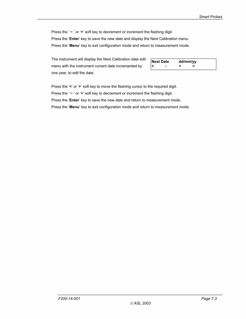
The instrument will display the Next Calibration date edit Next Date dd/mm/yy < - + > menu with the instrument current date incremented by
one year, to edit the date.
Press the ‘<’ or ‘>’ soft key to move the flashing cursor to the required digit.
Press the ‘ ’ or ‘+’ soft key to decrement or increment the flashing digit.
Press the ‘Enter’ key to save the new date and return to measurement mode.
Press the ‘Menu’ key to exit configuration mode and return to measurement mode.
F200-14-001 Page 7-3
ASL 2003

Calibrating the F200
This page is intentionally left blank.
Page 7-4 F200-14-001
ASL 2003

8. Communications Interface
8.1 Introduction
The F200 is fitted with an RS-232 serial communication interface as standard.
8.2 Overview of the RS-232 Serial Interface
This conforms to specification ANSI/EIA/TIA-232-E-1991 Interface Between Data Terminal Equipment
(DTE) and Data Circuit-Terminating Equipment (DCE) employing serial binary data interchange.
Signal levels; MARK (logical ‘1’); -3V to -15V
SPACE (logical ‘0’); +3V to +15V
Data is transferred using the TXD (transmit data) and RXD (receive data) lines.
Data flow control is by the RTS (request to send) and CTS (clear to send) lines to prevent data loss
due to an instrument receiver buffer overflow. RTS is an output from the instrument that indicates its
receiver status. When asserted (low), it indicates that it is ready to receive another character. When
negated (high), the instrument receiver buffer is full and cannot receive another character until the
buffer is processed (if the PC sends one, it may be lost). As soon as space becomes available in the
receiver buffer, RTS is re-asserted to allow the PC to send the next character.
When the instrument detects receipt of a command terminator character, RTS is negated whilst the
command line buffer is read and validated. This is to prevent the PC sending further characters whilst
a command is being validated. Following validation, RTS is re-asserted to permit the next command
to be transmitted by the PC.
CTS is an input to the instrument and controls the transmission of characters. If the PC asserts CTS
(low), then the instrument will transmit the next character from the output buffer (if one is waiting). If
the PC negates CTS (high), then the instrument will not transmit the character, but will wait until CTS
is re-asserted. TXD will remain in the mark (low) condition whilst CTS is negated. Note that changing
CTS during transmission of a character will not disrupt the transmission of that character.
F200-14-001 Page 8-1
ASL 2003

Communications Interface
8.2.1 The RS-232 Connector
RS-232 connection is via a 9-way (plug) D-type connector on the back panel as shown in Figure 8.2.
View towards rear panel
RS232 connector
Figure 8.2 - RS-232 Connector
8.2.2 Pin Connections
Computer Instrument
25-Pin Connector
9-Pin Connector
Function 9-Pin Connector
Function
3 2 Rx 3 Tx
2 3 Tx 2 Rx
7 5 GND 5 GND
6 6 DSR
4 7 RTS 8 CTS
5 8 CTS 7 RTS
To make an RS232 connection, use fully screened cable assemblies to maintain EMC integrity. A 5-
wire (TXD, RXD, GND, RTS, CTS) cross over cable is recommended.
A 3 wire connection (TXD, RXD, GND) is not recommended, but may be implemented by connecting
RTS and CTS together at the instrument end. In this case, the DTE must not send characters too
quickly as this will cause the instrument receive buffer to overflow, leading to lost data.
8.3 RS-232 Settings
The RS232 serial interface command set follows the SCPI format.
Input data flow will be controlled via RTS, CTS lines to prevent input buffer overflow occurring.
The instrument can be set to function in one of two serial communication modes, Talk only mode or
Remote mode.
Page 8-2 F200-14-001
ASL 2003

Communications Interface
8.3.1 Talk only mode (Auto output)
Talk only mode can be set On or Off from the instrument Options menu, its selected state is saved in
the instrument internal none-volatile memory and retrieved at power up.
In talk only mode the instrument ignores all incoming commands and remains under local control.
On completion of each measurement the instrument will automatically output the channel number,
measurement value and units over the RS232 serial interface port.
Talk only mode is useful for outputting data directly to a serial printer without the need for a PC.
8.3.2 Remote mode (Local lockout)
In Remote mode the instrument can only be controlled over the RS232 serial interface port, the
instrument front panel keys are locked out.
To enable Remote mode the instrument must first be set for Remote mode operation.
8.3.3 Power up state
Talk only mode: State recalled from instrument none-volatile memory.
Remote mode: Off.
8.3.4 Communication protocol
Baud rate fixed at 9600
Data bits 8
Stop bit 1
Start bit 1
Parity none
8.3.5 Programming command syntax
The programming command language is based on the SCPI command format. Commands consist of
one or more command words with each command word separated by a colon (:), a question mark (?)
for a command requiring a response, a white space character used to separate the first parameter
from the command words, a list of parameters (<parameter>) with each parameter separated by a
comma (,), followed by a command terminator carriage return (CR) or carriage return line feed
(CR)(LF).
Colon (:) Separates command words.
Question mark (?) Command requires a response.
Comma (,) Separates parameters list.
F200-14-001 Page 8-3
ASL 2003

Communications Interface
8.3.6 Long form short form commands
Command words have a long form and short form version, the short form version is indicated by
upper case characters.
Example:
SYSTem:REMote long form
SYST:REM short form
8.3.7 Case sensitivity
Command words are not case sensitive, you can use upper or lower case characters or any
combination. Example:
SYSTEM:REMOTE = system:remote
8.3.8 Command Terminators (CR) or (CR)(LF)
All commands sent to the instrument must be terminated with a carriage return (CR) character. It is
permitted to send (CR)(LF) to terminate a message; the (LF) is ignored.
8.3.9 Input Buffer
The instrument receives messages into an input buffer and only starts executing commands after
receipt of a command terminator.
8.3.10 Output Data Format
Non-reading queries <80 ASCII character string
Reading Temperature SDDDD.DDD (CR) (LF)
Resistance SDDD.DDDD (CR) (LF)
Talk Only format Chx, SDDDD.DDD, “Units” (CR) (LF)
where Chx = channel number
S = sign ( negative, blank positive)
D = decimal Digit (0-9)
“Units” = selected measurement units C, F, K or R
(CR) = carriage return character
(LF) = linefeed character
Page 8-4 F200-14-001
ASL 2003

Communications Interface
8.4 RS-232 Interface Commands
8.4.1 SYSTem:REMote
Command SYST:REM
SYSTEM:REMOTE
Return None
Function Place the instrument in remote mode for RS232 interface control.
Display rem on the instrument display.
Abort the current measurement cycle.
Clear the last reading from the display.
Clear the output buffer.
Lock out the instrument front panel keys.
Set the trigger mode to Single shot.
Place the instrument in Hold mode.
8.4.2 SYSTem:LOCal
Command SYST:LOC
SYSTEM:LOCAL
Return None
Function Return the instrument to local mode.
Remove rem from the instrument display.
Enable the instrument front panel keys.
Set the instrument in Hold mode.
8.4.3 *IDN?
Command *IDN?
Return <manufacturer>,<model no>,<serial no>,<firmware version>
Parameters <manufacture> ASL
<model no> F200
<serial no> Serial number of the instrument.
<firmware version> Current firmware version and date.
Function Read the instrument’s identification code consisting of the manufacturer
name, instrument model number, instrument serial number, firmware version
and date.
F200-14-001 Page 8-5
ASL 2003

Communications Interface
8.4.4 CAL:DATE <year>,<month>,<day>
Command CAL:DATE <year>,<month>,<day>
Parameters <year> 4 digit numerical string
<month> 1 to 12 for month
<day> 1 to 7 for day
Return -203 Password protected
Protection Password protected command.
Function Enter the instrument calibration date.
8.4.5 CAL:DATE?
Command CAL:DATE?
Return <year>,<month>,<day>
Parameters <year> 4 digit numerical string
<month> 1 to 12 for month
<day> 1 to 7 for day
Function Query the instrument calibration date.
8.4.6 CAL:NEXTDATE <year>,<month>,<day>
Command CAL:NEXTDATE <year>,<month>,<day>
Parameters <year> 4 digit numerical string
<month> 1 to 12 for month
<day> 1 to 7 for day
Return -203 Password protected
Protection Password protected command.
Function Enter the instrument next calibration date. At power up this date is compared
with the instrument current date to determine if the instrument calibration
date has expired.
8.4.7 CAL:NEXTDATE?
Command CAL:NEXTDATE?
Return <year>,<month>,<day>
Parameters <year> 4 digit numerical string
<month> 1 to 12 for month
<day> 1 to 7 for day
Function Query the instrument next calibration date.
Page 8-6 F200-14-001
ASL 2003

Communications Interface
8.4.8 System Command Summary
Command Description
SYSTem:PASSword:DEFAult Sets password to the default value.
SYSTem:PASSword:CENable Enable protected commands.
SYSTem:PASSword:CENable:STATe? Queries the password cenable state.
SYSTem:PASSword:CDISable Disable protected commands.
SYSTem:PASSword:NEW Change the system password.
SYSTem:BEEPer:IMMediate Sounds a single beep immediately.
SYSTem:TIME Sets the internal clock time.
SYSTem:TIME? Queries the internal clock time.
SYSTem:DATE Sets the internal clock date.
SYSTem:DATE? Queries the internal clock date.
CAL:DATE Sets the instrument calibration date.
CAL:DATE? Queries the instrument calibration date.
CAL:NEXTDATE Sets the instrument next calibration date.
CAL:NEXTDATE? Queries the instrument next calibration date.
F200-14-001 Page 8-7
ASL 2003

Communications Interface
8.5 Measurement Command Group
The measurement command group is used to select channels, configure channel parameters and
acquire readings.
8.5.1 CONFigure:CHANnel <channel>
Command CONF:CHAN <channel>
CONFIGURE:CHANNEL <channel>
Return None
Parameters <channel> 1 to 8 single channel measurement
Chx-Chy differential measurement mode.
Function Select the specified channel to be measured without initiating a
measurement, only channels that are available can be selected.
Abort the current measurement cycle.
Clear the last measurement from the display.
Clear the output buffer.
Set the instrument to Hold.
8.5.2 CONFigure?
Command CONF?
CONFIGURE?
Return <channel>,<standard>
Parameters <channel> 1 to 8 single channel measurement.
Chx-Chy differential measurement mode.
<standard> 1 Din90 (EN60751)
2 CvD
3 ITS90
Function Query the current selected channel and its configuration.
8.5.3 FETch?
Command FET?
FETCH?
Return <channel>,<measurement>,<units>
Parameters <channel> 1 to 8 single channel measurement
X-Y differential measurement mode.
<measurement> last measurement value.
<units> currently selected units.
Function Transfer the last reading stored in the instrument’s internal memory by the
INITiate command to the instrument’s output buffer. After reading the
memory is cleared and further FETCh? commands do not return anything
until a fresh INITiate command is sent.
Page 8-8 F200-14-001
ASL 2003
Communications Interface
8.5.4 READ?
Command READ?
Return <channel>,<measurement>,<units>
Parameters <channel> 1 to 8 single channel measurement
X-Y differential measurement mode.
<measurement> last measurement value.
<units> currently selected units.
Function Initiate a measurement of the current selected input channel, the reading is
sent directly to the instrument’s output buffer.
If TRIGger mode is set to SINGle shot, only one reading is taken and the
instrument returns to Hold mode.
If TRIGger mode set to INFinite, continuous readings are taken with all
readings sent to the output buffer.
8.5.5 MEASure Command
The MEASure commands work similar to the CONFigure commands, except that an immediate
measurement is performed with the result being sent to the output buffer.
8.5.6 MEASure:CHANnel? <channel>
Command MEAS:CHAN? <channel>
MEASURE:CHANNEL? <channel>
Parameters <channel> 1 to 8 single channel measurement
Chx-Chy differential measurement mode.
Return <channel>,<measurement>,<units>
Parameters <channel> 1 to 8 single channel measurement
X-Y differential measurement mode.
<measurement> last measurement value.
<units> currently selected units.
Function Abort the current measurement cycle.
Clear the last measurement from the display.
Clear the output buffer.
Select the channel as specified initiate a measurement, the reading is sent
directly to the instrument’s output buffer.
If TRIGger mode is set to SINGle shot, only one reading is taken and the
instrument returns to Hold mode.
If TRIGger mode set to INFinite, continuous readings are taken with all
readings sent to the output buffer.
F200-14-001 Page 8-9
ASL 2003

Communications Interface
8.6 UNIT Command Group The UNIT command group is used to control the instrument global parameters.
8.6.1 UNIT:TEMPerature <units>
Command UNIT:TEMP <units>
UNIT:TEMPERATURE <units>
Parameters <units> C or CEL Degrees Celcius
F or FAR Degrees Fahrenheit
K Degrees Kelvin
R Resistance
Return None
Function Set the global temperature units.
Clear the last measurement from the display.
8.6.2 UNIT:TEMPerature?
Command UNIT:TEMP?
UNIT:TEMPERATURE?
Return <units>
Parameters <units> C or CEL Degrees Celcius
F or FAR Degrees Fahrenheit
K Degrees Kelvin
R Resistance
Function Query the global temperature units.
Page 8-10 F200-14-001
ASL 2003
Communications Interface
8.7 Trigger Command Group The TRIGger commands are used to control the instruments operation.
8.7.1 INITiate
Command INIT
INITIATE
Return None
Function Abort the current measurement cycle.
Clear the last measurement from the display.
Clear the output buffer.
Set the trigger mode to Single shot.
Initiate a single measurement of the current selected input channel without
returning a reading, up date the instrument display with the new reading.
Return the instrument to Hold.
Use the FETCh? command to transfer the reading to the output buffer.
8.7.2 ABORt
Command ABOR
ABORT
Return None
Function Abort the current measurement cycle.
Clear the last measurement from the display.
Clear the input and output buffers.
Set the trigger mode to single shot.
Set the instrument to Hold.
8.7.3 TRIGger:MODE <mode>
Command TRIG:MODE <mode>
TRIGGER:MODE <mode>
Parameters <mode> SINGle Single shot trigger mode
INFinite Infinite trigger mode (Run/Hold)
Return None
Function Set the trigger mode to single shot measurement or infinite measurement.
Setting trigger mode to single shot results in a single measurement when
initiated.
In infinite mode continuous measurement are taken when the Measure? or
Read? commands are sent.
Abort the current measurement cycle.
Clear the last measurement from the display and output buffer.
Set the trigger mode to the state as defined by the command
Set the instrument to Hold.
F200-14-001 Page 8-11
ASL 2003

Communications Interface
8.8 System Related Commands The SYSTem commands are used to control the instrument none-measurement global
parameters.
Protected data Calibration data, smart probe data.
The instrument will return the error code -203 if a password protected command is received that
is currently disabled.
8.8.1 SYSTem:PASSword:DEFAult
Command SYST:PASS:DEFA
SYSTEM:PASSWORD:DEFAULT
Return None
Function Set the instrument password to the default password.
Default password = 9900
8.8.2 SYSTem:PASSword:CENable <password>
Command SYST:PASS:CEN <password>
SYSTEM:PASSWORD:CENABLE <password>
Parameters <password> 4 digit numerical string
Return -221 incorrect password sent
Function Allow the password protected data to be modified.
8.8.3 SYSTem:PASSword:CDISable <password>
Command SYST:PASS:CDIS <password>
SYSTEM:PASSWORD:CDISABLE <password>
Parameters <password> 4 digit numerical string
Return -221 incorrect password sent
Function Prevent the password protected data from being modified.
8.8.4 SYSTem:PASSword:CENable:STATe?
Command SYST:PASS:CEN:STAT?
SYSTEM:PASSWORD:CENABLE:STATE
Return <state>
Parameters <state> 0 Password protected commands disabled
(default at power up).
1 Password protected commands enabled.
Function Query the system command enable state.
Page 8-12 F200-14-001
ASL 2003

Communications Interface
8.8.5 SYSTem:PASSword:NEW <current password>,<new password>
Command SYST:PASS:NEW <current password>,<new password>
SYSTEM:PASSWORD:NEW <current password>,<new password>
Parameters <current password> 4 digit numerical string
<new password> 4 digit numerical string
Return -221
Function Change the system password.
8.8.6 SYSTem:BEEPer:IMMediate
Command SYST:BEEP:IMM
SYSTEM:BEEPER:IMMEDIATE
Return None
Function Sound a single beep immediately.
8.8.7 SYSTem:TIME <hour>,<minute>,<second>
Command SYST:TIME <hour>,<minute>,<second>
SYSTEM:TIME <hour>,<minute>,<second>
Parameters <hour> 0 to 23 set hours
<minute> 0 to 59 set minutes
<second> 0 to 59 set seconds
Return None
Function Set the system calendar/clock time value.
The instrument uses the 24-hour clock format.
8.8.8 SYSTem:TIME?
Command SYST:TIME?
SYSTEM:TIME?
Return <hour>:<minute>:<second>
Parameters <hour> 0 to 23 set hours
<minute> 0 to 59 set minutes
<second> 0 to 59 set seconds
Function Query the system calendar/clock time value.
The instrument uses the 24-hour clock format.
F200-14-001 Page 8-13
ASL 2003
Communications Interface
8.8.9 SYSTem:DATE <year>, <month>, <day>
Command SYST:DATE <year>,<month>,<day>
SYSTEM:DATE <year>,<month>,<day>
Parameters <year> 4 digit numerical string
<month> 1 to 12 set minutes
<day> 1 to 7 set seconds
Return None
Function Set the system calendar/clock date value.
8.8.10 SYSTem:DATE?
Command SYST:DATE?
SYSTEM:DATE?
Return <year>,<month>,<day>
Parameters <year> 4 digit numerical string for year
<month> 1 to 12 for month
<day> 1 to 7 for day
Function Query the system calendar/clock date value.
Page 8-14 F200-14-001
ASL 2003
Communications Interface
8.9 SENSe Command Group The SENSe command group is used to control the instrument measurement parameters.
8.9.1 SENSe:ZERO:AUTO <mode>
Command SENS:ZERO:AUTO <mode>
SENSE:ZERO:AUTO <mode>
Parameters <mode> 1 or ON Auto-zero mode on
0 or OFF Auto-zero mode off
Return None
Function Set the auto-zero mode on or off for relative measurements to a fixed offset.
The Zero mode LED on the instrument front panel indicates the current
selected mode.
8.9.2 SENSe:ZERO:AUTO?
Command SENS:ZERO:AUTO?
SENSE:ZERO:AUTO?
Return <mode>
Parameters <mode> 1 Auto-zero mode ON
0 Auto-zero mode OFF
Function Query the auto-zero mode.
8.9.3 SENSe:FRTD:CAL:DATE <year>,<month>,<day>
Command SENS:FRTD:CAL:DATE <year>,<month>,<day>
SENSE:FRTD:CALIBRATION:DATE <year>,<month>,<day>
Parameters <year> 4 digit numerical string
<month> 1 to 12 for month
<day> 1 to 7 for day
Return -203 Password protected
-222 No smart probe detected
Protection Password protected command.
Function Enter the calibration date to the selected smart probe, save the old
calibration date in history. Clear the max and min recorded values outside
working range since last cal.
F200-14-001 Page 8-15
ASL 2003

Communications Interface
8.9.4 SENSe:FRTD:CAL:DATE?
Command SENS:FRTD:CAL:DATE?
SENSE:FRTD:CALIBRATION:DATE?
Return <year>,<month>,<day>
-222 No smart probe detected
Parameters <year> 4 digit numerical string
<month> 1 to 12 for month
<day> 1 to 7 for day
Function Query the calibration date for the selected smart probe.
8.9.5 SENSe:FRTD:CAL:NEXT <year>,<month>,<day>
Command SENS:FRTD:CAL:NEXT <year>,<month>,<day>
SENSE:FRTD:CALIBRATION:NEXT <year>,<month>,<day>
Parameters <year> 4 digit numerical string
<month> 1 to 12 for month
<day> 1 to 7 for day
Return -203 Password protected
-222 No smart probe detected
Protection Password protected command.
Function Enter the next calibration date to the selected smart probe.
8.9.6 SENSe:FRTD:CAL:NEXT?
Command SENS:FRTD:CAL:NEXT?
SENSE:FRTD:CALIBRATION:NEXT?
Return <year>,<month>,<day>
-222 No smart probe detected
Parameters <year> 4 digit numerical string
<month> 1 to 12 for month
<day> 1 to 7 for day
Function Query the next calibration date for the selected smart probe.
Page 8-16 F200-14-001
ASL 2003

Communications Interface
8.9.7 SENSe:FRTD:CAL:HISTory?
Command SENS:FRTD:CAL:HIST?
SENSE:FRTD:CALIBRATION:HISTORY?
Return <year>,<month>,<day> Provided in a list format x dates long.
-222 No smart probe detected
Parameters <year> 4 digit numerical string
<month> 1 to 12 for month
<day> 1 to 7 for day
Function Query the calibration date history for the selected smart probe.
8.9.8 SENSe:FRTD:CAL:SOURce <source>
Command SENS:FRTD:CAL:SOUR <source>
SENSE:FRTD:CALIBRATION:SOURCE <source>
Parameters <source> 20 byte maximum ASCII string.
Return -203 Password protected
-222 No smart probe detected
Protection Password protected command.
Function Save the calibration source reference code to the selected smart probe.
8.9.9 SENSe:FRTD:CAL:SOURce?
Command SENS:FRTD:CAL:SOUR?
SENSE:FRTD:CALIBRATION:SOURCE?
Return <source>
-203 Password protected
-222 No smart probe detected
Parameters <source> 20 byte maximum ASCII string.
Protection Password protected command.
Function Query the calibration source reference code for the selected smart probe.
8.9.10 SENSe:FRTD:FORMat <format>
Command SENS:FRTD:FORM <format>
SENSE:FRTD:FORMAT <format>
Parameters <format> 1 Smart probe data format 1.
Return -203 Password protected
-222 No smart probe detected
Protection Password protected command.
Function Enter the data code format used for the selected smart probe.
F200-14-001 Page 8-17
ASL 2003
Communications Interface
8.9.11 SENSe:FRTD:FORMat?
Command SENS:FRTD:FORM?
SENSE:FRTD:FORMAT?
Return <format>
-222 No smart probe detected
Parameters <format> 1 Smart probe data format 1.
Function Query the data code format used for the selected smart probe.
8.9.12 SENSe:FRTD:STANdard <standard>
Command SENS:FRTD:STAN <standard>
SENSE:FRTD:STANDARD <standard>
Parameters <standard> 1 Din90 (EN60751)
2 CvD
3 ITS90
Return None
Protection Password protected command.
Function Set the selected channel temperature conversion method.
Smart probe input save to smart probe.
None smart probe input save to instrument internal channel configuration.
8.9.13 SENSe:FRTD:STANdard?
Command SENS:FRTD:STAN?
SENSE:FRTD:STANDARD?
Return <standard>
Parameters <standard> 1 Din90 (EN60751)
2 CvD
3 ITS90
Function Query the selected channel temperature conversion method.
Smart probe input query the smart probe.
None smart probe input query the instrument internal channel configuration.
Page 8-18 F200-14-001
ASL 2003

Communications Interface
8.9.14 SENSe:FRTD:COEFficient <coefficient>,<value>
Command SENS:FRTD:COEF <coefficient>,<value>
SENSE:FRTD:COEFFICIENT <coefficient>,<value>
Parameters <coefficient> Ap, Bp, Cp, Dp, R0, Wt, An or Bn
<value> Scientific notation to six decimal places eg 3.908300e-03
R0 as a decimal to six decimal places eg 100.123456
Return None
Protection Password protected command.
Function Set the selected input channel specified coefficient value.
Smart probe input save to smart probe.
None smart probe input save to instrument internal channel configuration.
8.9.15 SENSe:FRTD:COEFficient? <coefficient>
Command SENS:FRTD:COEF? <coefficient>
SENSE:FRTD:COEFFICIENT? <coefficient>
Parameters <coefficient> Ap, Bp, Cp, Dp, R0, Wt, An, Bn or all
Return <value> Scientific notation to six decimal places eg 3.908300e-03
R0 as a decimal to six decimal places eg 100.123456
Function Query the selected input channel specified coefficient value.
Smart probe input query the smart probe.
None smart probe input query the instrument internal channel configuration.
8.9.16 SENSe:FRTD:IDENtification <identification>
Command SENS:FRTD:IDEN <identification>
SENSE:FRTD:IDENTIFICATION <identification>
Parameters <identification> 20 byte maximum ASCII string
Return -203 Password protected
-222 No smart probe detected
Protection Password protected command.
Function Enter the identification number to the selected smart probe.
F200-14-001 Page 8-19
ASL 2003

Communications Interface
8.9.17 SENSe:FRTD:IDENtification?
Command SENS:FRTD:IDEN?
SENSE:FRTD:IDENTIFICATION?
Return <identification>
-222 No smart probe detected
Parameters <identification> 20 byte maximum ASCII string
Function Query the identification number for the selected smart probe.
8.9.18 SENSe:FRTD:RANGe <rmax>,<rmin>
Command SENS:FRTD:RANG <rmax>,<rmin>
SENSE:FRTD:RANGE <rmax>,<rmin>
Parameters <rmax> 0 to 400 ohm’s
<rmin> 0 to 400 ohm’s
Return -203 Password protected
-222 No smart probe detected
Protection Password protected command.
Function Enter the working range of the selected smart probe.
8.9.19 SENSe:FRTD:RANGe?
Command SENS:FRTD:RANG?
SENSE:FRTD:RANGE?
Return <rmax>,<rmin> smart probe working range
<rmax>,<rmin> recorded value outside working range since last cal
<rmax>,<rmin> recorded value outside working range ever
-222 No smart probe detected
Parameters <rmax> 0 to 400 ohm’s
<rmin> 0 to 400 ohm’s
Protection Password protected command.
Function Query the working range and working history of the smart probe.
Page 8-20 F200-14-001
ASL 2003

Communications Interface
8.9.20 SENSe:FRTD:LOCK
Command SENS:FRTD:LOCK <state>
SENSE:FRTD:LOCK <state>
Parameters <state> 0 Smart probe data unlocked
1 Smart probe data locked
Return -203 Password protected
-222 No smart probe detected
Protection Password protected command.
Function Set the smart probe data protection state, before any smart probe data can
be changed it must first be unlocked.
8.9.21 SENSe:FRTD:LOCK?
Command SENS:FRTD:LOCK?
SENSE:FRTD:LOCK?
Return <state>
Parameters <state> 0 Smart probe data unlocked
1 Smart probe data locked
-222 No smart probe detected
Function Query the smart probe data protection lock state.
8.9.22 Command summary
Measurement command summary
Command Description
CONFigure:CHANnel Select the specified channel.
CONFigure? Query the channel configuration.
FETCh? Fetch a single reading.
READ? Initiate a measurement and fetch a reading.
MEASure:CHANnel? Select the specified channel.
Initiate a measurement and fetch a reading.
Unit command summary
Command Description
UNIT:TEMPerature Sets the temperature units to be used.
UNIT:TEMPerature? Queries the temperature units.
F200-14-001 Page 8-21
ASL 2003

Communications Interface
Trigger command summary
Command Description
INITiate Initiate a single measurement.
ABORt Abort the current measurement.
TRIGger:MODE Sets the trigger mode.
TRIGger:MODE? Queries the trigger mode.
System Command Summary
Command Description
SYSTem:PASSword:DEFAult Sets password to the default value.
SYSTem:PASSword:CENable Enable protected commands.
SYSTem:PASSword:CENable:STATe? Queries the password cenable state.
SYSTem:PASSword:CDISable Disable protected commands.
SYSTem:PASSword:NEW Change the system password.
SYSTem:BEEPer:IMMediate Sounds a single beep immediately.
SYSTem:TIME Sets the internal clock time.
SYSTem:TIME? Queries the internal clock time.
SYSTem:DATE Sets the internal clock date.
SYSTem:DATE? Queries the internal clock date.
Sense Command Summary
Command Description
SENSe:ZERO:AUTO Sets the auto-zero measurement mode.
SENSe:ZERO:AUTO? Queries the auto-zero measurement mode.
SENSe:FRTD:LOCK Set the smart probe data lock state.
SENSe:FRTD;LOCK? Query the smart probe data lock state.
SENSe:FRTD:CAL:DATE Sets the smart probe calibration date.
SENSe:FRTD:CAL:DATE? Queries the smart probe calibration date.
SENSe:FRTD:CAL:NEXT Sets the smart probe next calibration date.
SENSe:FRTD:CAL:NEXT? Queries the smart probe next calibration date.
SENSe:FRTD:CAL:HISTory? Queries the smart probe calibration date history.
SENSe:FRTD:CAL:SOURce Sets the calibration company reference code.
SENSe:FRTD:CAL:SOURce? Queries the calibration company reference code.
SENSe:FRTD:FORMat Sets the data format code in the smart probe.
SENSe:FRTD:FORMat? Queries the data format code in the smart probe.
SENSe:FRTD:STANdard Sets the temperature conversion type.
SENSe:FRTD:STANdard? Queries the temperature conversion type.
SENSe:FRTD:COEFficient Sets the temperature conversion coefficients.
SENSe:FRTD:COEFficient? Queries the temperature conversion coefficients.
SENSe:FRTD:IDENtification Sets the smart probe identification number.
SENSe:FRTD:IDENtification? Queries the smart probe identification number.
SENSe:FRTD:RANGe Sets the smart probe working range.
SENSe:FRTD:RANGe? Queries the smart probe working history.
Page 8-22 F200-14-001
ASL 2003

9. Options and Accessories
9.1 Accessories
The following expansion may be retrofitted to the F200:
Order Suffix Description
F200-2/8 Expansion from 2 to 8 channels
Other options available for the F200 include:
Part Number Description
FA-SMART Smart connector
FA-DIN5 5-pin DIN plug
FA-ADAP-250 Adaptor box to allow connection to spade terminal or free wire terminated PRTs
F200-CAL-A UKAS system calibration at -50, 0, +100 & +250°C
F200-CAL-B UKAS system calibration at -70, 0, +100 & +450°C
FA-SC200 Soft carry case
EXT-C Probe extension cable (DIN/DIN)
A range of standard probes are available:
Order Suffix Description
T100-200-1S 100$ un-calibrated PRT range –50 to +200°C Smart connector
T100-200-1S-NAM 100$"PRT UKAS calibration at –50 to +200°C Smart connector
T100-250-1S 100$ un-calibrated PRT range –50 to +250°C Smart connector
T100-250-1S-NAM 100$"PRT UKAS calibration at –50 to +250°C Smart connector
T100-450-1S 100$ un-calibrated PRT range –70 to +450°C Smart connector
T100-450-1S-NAM 100$"PRT UKAS calibration at –70 to +450°C Smart connector
F200-14-001 Page 9-1
ASL 2003

Options and Accessories
This page is intentionally left blank.
Page 9-2 F200-14-001
ASL 2003

10. Specification
10.1 Resistance thermometer measurement
PRT Characterisation ITS90
Din90 BS EN60751:1996, IEC60751:1983
CvD BSEN1904:1984, IEC751:1983
Resistance measurement range 1 to 400 ohm
Temperature measurement range ITS90 -200 to +962ºC
Din90 -200 to +850ºC
CvD -150 to +850ºC
Display resolution 0.001ºC
Resistance measurement uncertainty ± 4m$"*@ +20°C ±5°C)
Temperature coefficient (resistance measurement) 0.2ppm/°C (0.05mK/°C)
Long term stability (resistance measurement) ± 25ppm (±2.5m$) / year
Temperature measurement uncertainty Pt100 Over -200 to +800ºC ± 0.01ºC
Pt100 sense current 1mA (DC) polarity switchable
User selectable measurement display units R/ºC/ ºF/ K
Input channels 2, 4 or 8 expandable
Input connection 5 pin DIN
Measurement configuration 4 wire
Input impedance >10M"$
Max common and differential mode input voltage ±40VDC, 28Vrms
10.2 Display
User interface, display 128 x 18 High brightness dot graphic VFD display
10.3 Supply
Mains supply voltage range 90 – 264Vac
Power consumption: 30VA max
Supply frequency range 47 - 63Hz
F200-14-001 Page 10-1
ASL 2003

Specification
10.4 Environmental
Storage temperature range -20ºC to +50ºC
Service temperature range 0ºC to +40ºC
Specified operating temperature range +15ºC to +25ºC
Operating relative humidity conditions <80% RH, non-condensing
10.5 Dimensions
Precision Thermometer
215
Thermometer inputs
10
8
72
168
All dimensions in millimetres.
Weight: 1kg (2.2lbs)
10.6 Pt 100 System Accuracy
System accuracy is the combined accuracy of the F200 plus the calibration uncertainty of the PRT.
Accurate figures for the instrument and system with the range of calibrated PRTs available for the
F200 are shown below. These figures are based on a 1 year measurement uncertainty for the F200 of
&4 m$ which is equivalent to &10mK with PT100 PRT
F200 + T100-250-1 PRT (-50°C to +250°C)
-50°C 0°C +100°C +250°C
&20mK &20mK &20mK &20mK
F200 + T100-450 1 PRT (-70°C to +450°C)
-70°C -40°C 0°C +100°C +250°C +450°C
&40mK &20mK &20mK &20mK &20mK &100mK
Page 10-2 F200-14-001
ASL 2003
11. Cleaning and Maintenance
11.1 Cleaning
Make sure the F200 is disconnected from the mains supply before cleaning.
Clean the outside of the instrument with a soft, clean cloth dampened with mild detergent. Do not
allow water to enter the instrument.
WARNING: Never use alcohol or thinners as these will
damage the instrument.
Never use a hard or abrasive brush.
11.2 Preventive Maintenance
WARNING: Inspect the mains supply cable regularly
to ensure that insulation is not damaged.
11.3 General Safety Warning
WARNING: If the F200 is used in a manner not
specified by ASL, then the protection provided by the
instrument may be impaired.
F200-14-001 Page 11-1
ASL 2003

Cleaning and Maintenance
This page is intentionally left blank.
Page 11-2 F200-14-001
ASL 2003

12. Service and Warranty
F200 equipment and accessories, (unless stated otherwise), are covered by a 12 month warranty for
parts and labour from the date of dispatch from ASL. This warranty does not include costs incurred in
returning the equipment to the factory for repair.
12.1 Technical Support
For all technical support, repair, warranty and service inquiries please contact:
Customer Support Group ASL. 275 King Henry’s Drive New Addington Croydon
Surrey CR0 0AE UNITED KINGDOM Telephone: +44 (0)1689 800799 Fax: +44 (0)1689 800405
E-Mail: [email protected] Web Page: www.aslltd.co.uk
12.2 Returned Instruments
All returned goods should be sent carriage paid, insured and packed well, to the above address.
F200-14-001 Page 12-1
ASL 2003

This page is intentionally left blank.
Page 12-2 F200-14-001
ASL 2003