F S/ PKH AVG MODE - Paragon Instrument automation/MR1 MANUAL.pdf · WARRANTY Raytek warrants this...
130
MARATHON SERIES MR1S Marathon High Performance Integrated Ratio Infrared Thermometer Operator’s Manual Rev. C 10/00 56913-1 2C/1C MODE C/F F C 2C 1C S/ PKH AVG ▼ ▲ ∋
-
Upload
phungthuan -
Category
Documents
-
view
220 -
download
0
Transcript of F S/ PKH AVG MODE - Paragon Instrument automation/MR1 MANUAL.pdf · WARRANTY Raytek warrants this...

MA
RATH
ON
SERIES
MR1S
M a r a t h o nHigh PerformanceIntegrated RatioInfrared Thermometer
Operator’s Manual
Rev. C 10/0056913-1
2C/1CMODE
C/F
FC
2C
1C
S/
PKH
AVG
▼
▲ ∋

Internet Address: http://www.raytek.com
Raytek and Thermalert are registered trademarks of Raytek Corp. All other brands or products aretrademarks of their respective owners.
© 2000 Raytek Corporation
WORLDWIDE HEADQUARTERSRaytek Corporation
Box 1820, Santa Cruz, CA 95061-1820
Phone: (831) 458-1110 (800) 227-8074
FAX: (831) 458-1239
BRASILRaytek do Brasil
Phone: 55 15 233 6338
FAX: 55 15 233 6826
MEXICORaytek Mexico
Phone: 52 22 30 4380
FAX: 52 22 30 4438
JAPANRaytek Japan, Inc.
Phone: 81 3 3822 5715
FAX: 81 3 3822 5712
CHINARaytek China Company
Phone: 86 10 6437 0284
FAX: 86 10 6437 0285
EUROPEAN HEADQUARTERSRaytek GmbH
Phone: 49 30 478 0080
FAX: 49 30 471 0251
GREAT BRITAINRaytek UK Ltd.
Phone: 441 908 630800
FAX: 441 908 630900
FRANCERaytek France
Phone: 33 1 64 53 1540
FAX: 33 1 64 53 1544
WARRANTYRaytek warrants this instrument to be free from defects in material and workmanship under nor-mal use and service for the period of two years from date of purchase. This warranty extends onlyto the original purchaser. This warranty shall not apply to fuses, batteries, or any product whichhas been subject to misuse, neglect, accident, or abnormal conditions of operation.
In the event of failure of a product covered by this warranty, Raytek will repair the instrumentwhen it is returned to an authorized Service Facility within two years of the original purchase,provided the warrantor’s examination discloses to its satisfaction that the product was defective.The warrantor may, at its option, replace the product in lieu of repair. With regard to any instru-ment returned within two years of the original purchase, said repairs or replacement will be madewithout charge. If the failure has been caused by misuse, neglect, accident, or abnormal conditionsof operation, repairs will be billed at nominal cost. In such cases, an estimate will be submittedbefore work is started, if requested.
THE FOREGOING WARRANTY IS IN LIEU OF ALL OTHER WARRANTIES, EXPRESSEDOR IMPLIED, INCLUDING BUT NOT LIMITED TO ANY IMPLIED WARRANTY OF MER-CHANTIBILITY, FITNESS, OR ADEQUACY FOR ANY PARTICULAR PURPOSE OR USE.RAYTEK SHALL NOT BE LIABLE FOR ANY SPECIAL, INCIDENTAL OR CONSEQUEN-TIAL DAMAGES, WHETHER IN CONTRACT, TORT, OR OTHERWISE.
SOFTWARE WARRANTYRaytek Corporation does not warrant that the software described herein will function properly inevery hardware and software environment. This software may not work in combination withmodified or emulated versions of DOS operating systems, Windows operating environments,memory-resident software, less than 100% compatible DOS-compatible systems, or with comput-ers with inadequate memory.
Raytek warrants that the program disk is free from defects in material and workmanship, assum-ing normal use, for a period of one year. Except for this warranty, Raytek makes no warranty orrepresentation, either expressed or implied, with respect to this software or documentation,including its quality, performance, merchantability, or fitness for a particular purpose. As a result,this software and documentation are licensed “as is,” and the licensee (i.e., the User) assumes theentire risk as to its quality and performance.
The liability of Raytek under this warranty shall be limited to the amount paid by the User. In noevent shall Raytek be liable for any costs including but not limited to those incurred as a result oflost profits or revenue, loss of use of the computer software, loss of data, the cost of substitute soft-ware, claims by third parties, or for other similar costs.
Raytek software and documentation are copyrighted with all rights reserved. It is illegal to makecopies for another person.


Table of Contents
PART 1 INTRODUCTION
About This Manual ..................................................................................................................2
Where to Start ............................................................................................................................2
1.0 Product Description....................................................................................................3
1.1 Theory of Operation...................................................................................................4
1.1.1 Parially Obscured Targets .......................................................................................41.1.2 Targets Smaller than Field of View........................................................................51.1.3 Low or Changing Emissivities ...............................................................................5
1.2 Accessories...................................................................................................................6
1.3 Options .........................................................................................................................6
1.4 Specifications...............................................................................................................8
1.4.1 Optical........................................................................................................................81.4.2 Thermal......................................................................................................................91.4.3 Operational..............................................................................................................111.4.4 Electrical ..................................................................................................................121.4.5 Physical....................................................................................................................121.4.6 Environmental ........................................................................................................13
1.5 Mechanical .................................................................................................................14
1.5.1 Sensors .....................................................................................................................141.5.2 Accessories and Options .......................................................................................15
1.5.2.1 Fixed Mounting Bracket.....................................................................................151.5.2.2 Air Purge Collar ..................................................................................................161.5.2.3 Polarizing Filter ...................................................................................................161.5.2.4 ThermoJacket and Accessories..........................................................................17
1.5.3 Cables.......................................................................................................................18
1.6 Factory Default Values .............................................................................................19
Marathon MR1S Operator’s Manual Table of Contents

Table of Contents Marathon MR1S Operator’s Manual
PART 2 NON-MULTIDROP INSTALLATION & OPERATION
2.0 Installation .................................................................................................................23
2.1 Preparation ................................................................................................................23
2.1.1 Ambient Temperature ...........................................................................................232.1.2 Atmospheric Quality .............................................................................................242.1.3 Electrical Interference ............................................................................................242.1.4 Sensor Location ......................................................................................................25
2.2 Mechanical Installation ............................................................................................27
2.2.1 Mounting the Sensor .............................................................................................272.2.2 Aiming and Focusing ............................................................................................27
2.3 Electrical Installation................................................................................................28
2.3.1 Power .......................................................................................................................282.3.2 RS-485 Interface Converter ...................................................................................302.3.3 Milliamp Output ....................................................................................................322.3.4 Relay Outputs.........................................................................................................32
2.4 Operation ...................................................................................................................33
2.4.1 The Control Panel ..................................................................................................332.4.2 Set-up .......................................................................................................................34
2.4.2.1 2-Color/1-Color Operation................................................................................342.4.2.2 Modes ...................................................................................................................35
Temperature .........................................................................................................35Slope/Emissivity.................................................................................................35Peak Hold (PKH).................................................................................................37Averaging (AVG).................................................................................................39
2.4.2.3 Setpoint.................................................................................................................402.4.2.4 Deadband .............................................................................................................402.4.2.5 Resetting Factory Defaults.................................................................................40
PART 3 MULTIDROP INSTALLATION & OPERATION
3.0 Multidrop Sensor Installation .................................................................................43
3.1 Multidrop Preparation .............................................................................................43
3.1.1 Ambient Temperature ...........................................................................................433.1.2 Atmospheric Quality .............................................................................................443.1.3 Electrical Interference ............................................................................................443.1.4 Sensor Location ......................................................................................................453.1.5 Multidrop Considerations ....................................................................................47
3.2 Network Communication Setup ............................................................................48
3.2.1 Software Installation..............................................................................................483.2.2 Preparing the Sensors for a 4-Wire Multidrop Installation..............................493.2.3 Preparing the Sensors for a 2-Wire Multidrop Installation..............................54
3.3 Multidrop Mechanical Installation.........................................................................56
3.3.1 Mounting the Sensor .............................................................................................563.3.2 Aiming and Focusing ............................................................................................56
3.4 Multidrop Electrical Installation.............................................................................57
3.4.1 Power .......................................................................................................................583.4.2 RS-485 Interface Converter ...................................................................................593.4.3 Milliamp Output ....................................................................................................613.4.4 Relay Outputs.........................................................................................................613.4.5 2-Wire Electrical Installation.................................................................................623.4.6 4-Wire Electrical Installation.................................................................................63
3.5 Operation ...................................................................................................................64
3.5.1 The Control Panel ..................................................................................................643.5.2 Set-up .......................................................................................................................65
3.5.2.1 2-Color/1-Color Operation................................................................................653.5.2.2 Modes ...................................................................................................................66
Temperature .........................................................................................................66Slope/Emissivity.................................................................................................66Peak Hold (PKH).................................................................................................68Averaging (AVG).................................................................................................70
3.5.2.3 Setpoint.................................................................................................................713.5.2.4 Deadband .............................................................................................................713.5.2.5 Resetting Factory Defaults.................................................................................72
Marathon MR1S Operator’s Manual Table of Contents
Table of Contents Marathon MR1S Operator’s Manual
PART 4 MARATHON SUPPORT SOFTWARE INSTALLATION & USER GUIDES
Software Installation..............................................................................................................74
4.0 Marathon Support Software Programs .................................................................75
4.1 Graphic Setup and Display Program.....................................................................75
4.2 Sensor Network Setup and Display Program ......................................................81
4.3 Marathon Chat Program..........................................................................................85
APPENDICES
Appendix A: Troubleshooting and Maintenance ...............................................................89
A.1 Troubleshooting Minor Problems...........................................................................89
A.2 Fail-safe Operation ...................................................................................................90
A.3 Cleaning the Window ..............................................................................................93
A.4 Changing the Window.............................................................................................94
Appendix B: Programming Guide........................................................................................95
B.1 Introduction...............................................................................................................95
B.2 Protocols Description ...............................................................................................96
B.2.1 Poll Versus Burst Modes .....................................................................................100B.2.2 The Burst Mode ....................................................................................................100
B.3 Remote Versus Manual Considerations ..............................................................101
B.4 Response Time in Setup Mode..............................................................................102
Appendix C: Slope and Emissivity.....................................................................................103
Appendix D: DIN Connector Wiring .................................................................................107
Appendix E: Traceability of Instrument Calibration .......................................................109
Appendix F: CE Conformity for the European Community...........................................111
Glossary ...................................................................................................................................113

Marathon MR1S Operator’s Manual 1
Part 1 Introduction
This section covers manual layout and product information, and it points you in theright direction to install and operate your sensor or sensors in a non-multidrop ormultidrop networked environment.
Topics include...
• About this Manual• Where to Start• Product Description• Product Specifications• Accessories and Options

2 Marathon MR1S Operator’s Manual
ABOUT THIS MANUAL
The Marathon MR1S Operator’s Manual provides detailed information about MarathonSeries™ infrared thermometers and supporting software. It is designed to be used asa reference tool in the installation and operation of your sensor or sensors.
This manual is organized according to the type of process environment you areinstalling into, whether it is a non-multidrop, non-networked installation or a mul-tidrop, networked installation.
• Part 1 discusses manual usage, product descriptions and specifications, andwhat section of the manual, either Part 2 or Part 3, to go to for information oninstallation and operation for your particular environment.
• Part 2 covers the installation and operation Marathon sensors in a non-mul-tidrop, non-networked process environment. If you are using Part 2 as aninstallation and operating guide, you do not need Part 3.
• Part 3 explains the installation, communication setup, and operation of one or upto 32 Marathon sensors in a multidrop network. If you are using Part 3 as aguide, you do not need Part 2.
• Part 4 describes how to use the three supplied Marathon utility programs. Twoprograms can be used in any Marathon sensor environment, one program is for amultidrop network environment only.
• Appendices are made up of a Programming Guide, which lists the communica-tions protocols for Marathon sensors; an Emissivity Guide, which shows exam-ples of emissivity settings for various metals and non-metals; a DIN connectorwiring chart; information on calibration traceability; and data on CE conformityfor the European community.
WHERE TO START
Whether you are planning to install a single sensor, multiple sensors, or an intercon-nected sensor network, you must first prepare for installation. Use the followingguide to go to the section that pertains to your type of installation:
• One Sensor/no Computer–Go to Part 2.
• One Sensor/Computer/non-multidrop–Go to Part 2.
• Each Additional Sensor/Computer/non-multidrop–Go to Part 2.
• One or More Sensors/Computer/future multidrop network–Go to Part 3.
• One or More Sensors/Computer/multidrop network–Go to Part 3.
Marathon MR1S Operator’s Manual 3
1.0 PRODUCT DESCRIPTION
The Thermalert Marathon MR1S series of instruments are 2-color infrared noncontacttemperature measurement systems with variable focus, through-the-lens sighting,and parallax-free optics. They are energy transducers designed to measure accuratelyand repeatedly the amount of heat energy emitted from an object, and then convertthat energy into a measurable electrical signal. Temperature measurements can betaken using either of the following modes:
• 2-color mode– temperatures are determined from the ratio of two separate andoverlapping infrared bands. The 2-color mode is best for measuring the tem-perature of targets that are partially obscured (either intermittently or perma-nently) by other objects, openings, screens, or viewing windows that reduceenergy, and by dirt, smoke, or steam in the atmosphere. The 2-color mode canalso be used on targets that do not completely fill the measurement spot, pro-vided the background is much cooler than the target.
• 1-color mode–for standard temperature measurements. The 1-color mode isbest for measuring the temperature of targets in areas where no sightingobstructions, either solid or gaseous, exist. The 1-color mode is also best wherethe target completely fills the measurement spot and where the background orforeground are higher in temperature than the target.
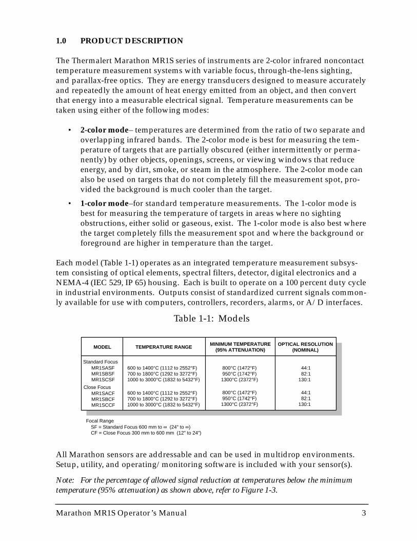
Each model (Table 1-1) operates as an integrated temperature measurement subsys-tem consisting of optical elements, spectral filters, detector, digital electronics and aNEMA-4 (IEC 529, IP 65) housing. Each is built to operate on a 100 percent duty cyclein industrial environments. Outputs consist of standardized current signals common-ly available for use with computers, controllers, recorders, alarms, or A/D interfaces.
Table 1-1: Models
All Marathon sensors are addressable and can be used in multidrop environments.Setup, utility, and operating/monitoring software is included with your sensor(s).
Note: For the percentage of allowed signal reduction at temperatures below the minimumtemperature (95% attenuation) as shown above, refer to Figure 1-3.
MR1SASFMR1SBSFMR1SCSF
MR1SACFMR1SBCFMR1SCCF
800°C (1472°F)950°C (1742°F)1300°C (2372°F)
44:182:1
130:1
800°C (1472°F)950°C (1742°F)1300°C (2372°F)
44:182:1
130:1
600 to 1400°C (1112 to 2552°F)700 to 1800°C (1292 to 3272°F)1000 to 3000°C (1832 to 5432°F)
600 to 1400°C (1112 to 2552°F)700 to 1800°C (1292 to 3272°F)1000 to 3000°C (1832 to 5432°F)
MODEL TEMPERATURE RANGE OPTICAL RESOLUTION(NOMINAL)
MINIMUM TEMPERATURE(95% ATTENUATION)
SF = Standard Focus 600 mm to ∞ (24" to ∞)CF = Close Focus 300 mm to 600 mm (12" to 24")
Standard Focus
Close Focus
Focal Range
4 Marathon MR1S Operator’s Manual
1.1 THEORY OF OPERATION
Two-color ratio technology makes possible accurate and repeatable temperature mea-surements that are free from dependence on absolute radiated energy values. In use,a 2-color sensor determines temperature from the ratio of the radiated energies in twoseparate wavelength bands (colors).
The benefits of 2-color sensors are that accurate measurements can be made under thefollowing conditions:
• When the field of view to the target is partially blocked or obscured.
• When the target is smaller than the sensor’s field of view.
• When target emissivities are low and/or changing by the same factor in bothwavelength bands.
Another benefit is that 2-color sensors measure closer to the highest temperaturewithin the measured spot (spatial peak picking) instead of an average temperature. A2-color sensor can be mounted farther away, even if the target does not fill the result-ing spot size. The convenience is that you are not forced to install the sensor at somespecific distance based upon target size and the sensor’s optical resolution.
1.1.1 Partially Obscured Targets
The radiated energy from a target is, in most cases, equally reduced when objects oratmospheric materials block some portion of the optical field of view. It follows thatthe ratio of the energies is unaffected, and thus the measured temperatures remainaccurate. A 2-color sensor is better than a 1-color sensor in the following conditions:
• Sighting paths are partially blocked (either intermittently or permanently).
• Dirt, smoke, or steam is in the atmosphere between the sensor and target.
• Measurements are made through items or areas that reduce emitted energy,such as grills, screens, small openings, or channels.
• Measurements are made through a viewing window that has unpredictableand changing infrared transmission due to accumulating dirt and/or moistureon the window surface.
• The sensor itself is subject to dirt and/or moisture accumulating on the lenssurface.
Note: 1-color sensors see polluted atmosphere and dirty windows and lenses as a reduction inenergy and give much lower than actual temperature readings.
Marathon MR1S Operator’s Manual 5
1.1.2 Targets Smaller Than Field of View
When a target is not large enough to fill the field of view, or if the target is movingwithin the field of view, radiated energies are equally reduced, but the ratio of theenergies is unaffected and measured temperatures remain accurate. This remains trueas long as the background temperature is much lower than the target’s. The follow-ing examples show where 2-color sensors can be used when targets are smaller thanthe field of view:
• Measuring wire or rod—often too narrow for field of view or moving or vibrat-ing unpredictably. It is much easier to obtain accurate results because sightingis less critical with two-color sensors.
• Measuring molten glass streams—often narrow and difficult to sight consis-tently with single-wavelength sensors.
1.1.3 Low or Changing Emissivities
If the emissivities in both wavelengths (colors) were the same, as they would be forany blackbody (emissivity = 1.0) or greybody (emissivity < 1.0 but constant), thentheir ratio would be 1, and target emissivity would not be an influence. However, innature there is no such thing as a greybody. The emissivity of all real objects changeswith wavelength and temperature, at varying degrees, depending on the material.
When emissivity is uncertain or changing, a 2-color sensor can be more accurate thana 1-color instrument as long as the emissivity changes by the same factor in bothwavelength bands. Note, however, that accurate measurement results are dependenton the application and the type of material being measured. To determine how to use2-color sensors with your application when uncertain or changing emissivities are afactor, please contact your sales representative.
6 Marathon MR1S Operator’s Manual
1.2 ACCESSORIES
A full range of accessories for various applications and industrial environments areavailable (see Figure 1-1). Accessories include items that may be ordered at any timeand added on-site. These include the following:
• Air purge collar• Fixed bracket• Adjustable bracket (included with sensor)• Swivel bracket• Mounting nut• Polarizing filter• Isolated 24 VDC power supply (110 or 220) or switching power supply with
universal input (110/220)• RS-485 to RS-232 interface converter (w/110V or 220V power supply)• 4, 8, 15, 30, or 60 meter (13, 26, 50, 100, or 200 feet) cable (For cable longer than
60 meters (200 feet), contact your sales representative.)• Field Calibration Package
Also available is a ThermoJacket™ (see Figure 1-1) and the following accessories:
• Adjustable mounting bracket• Mounting flange• Adjustable pipe adapter accessory• 305 mm (12 in) stainless steel (#300, schedule 40) sighting tube• 305 mm (12 in) ceramic sighting tube• Sighting tube mounting flange• Blast gate accessory• Focusing tool (to focus unit while in ThermoJacket or if mounted in recess)
Notes: Sensing heads are rated NEMA-4 (IEC 529, IP 65) with conduit adapter accessory andcompression fitting (which prevents liquid from entering through the connector).If you do not have a focusing tool accessory, the sensor must be focused before mount-ing inside a ThermoJacket or air purge collar.
1.3 OPTIONS
Options are items that are factory installed and must be ordered with base modelunits. The following are available:
• Air/water-cooled housing (see Figure 1-1)• NIST certification• Glass window endcap (easy viewing of LEDs) instead of standard endcap
WARNINGPolarizing filter will not fit in glass window endcap. Do not lookthrough the lens at extremely bright objects with your eyes unprotect-ed. Eye damage could occur.

Marathon MR1S Operator’s Manual 7
Fixed Bracket
Swivel BracketSensing Head With Air/Water-CooledHousing Option
Sensing Head
Adjustable Bracket
Mounting Nut
Air Purge Collar
Blast Gate Accessory
Sighting Tube Mounting Flange
ThermoJacket
Mounting Flange
Stainless Steel Sighting Tube
Ceramic Sighting TubeMounting Bracket
Adjustable Pipe Adapter Accessory
PolarizingFilter
Figure 1-1: Accessories and Options
IMPORTANTWhen reading this manual, look into exceptions that may result fromcustomized features. Check with your sales representative whenevera parameter is critical or operation seems abnormal.
8 Marathon MR1S Operator’s Manual
1.4 SPECIFICATIONS
The following sections cover optical, thermal, operational, electrical, and physicalspecifications for each model. (Specifications subject to change without notice.)
1.4.1 Optical
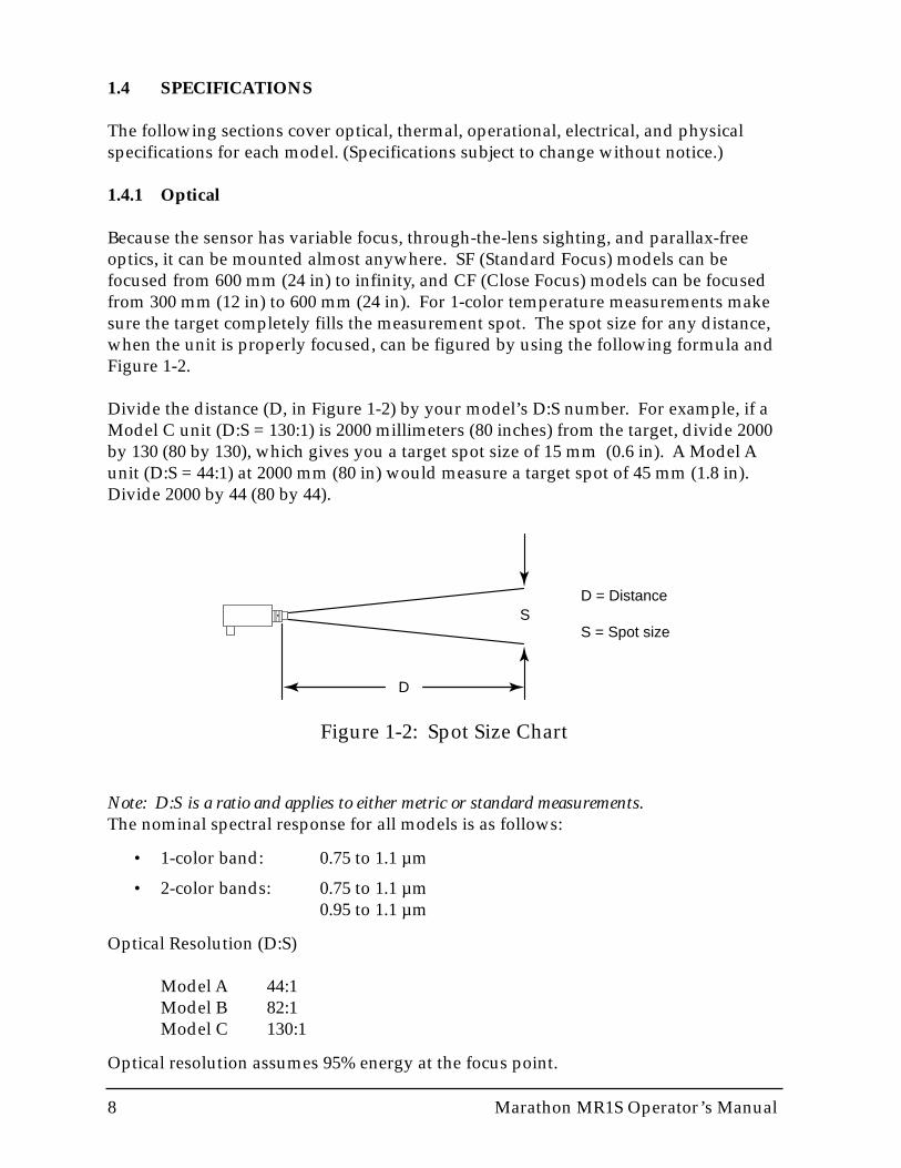
Because the sensor has variable focus, through-the-lens sighting, and parallax-freeoptics, it can be mounted almost anywhere. SF (Standard Focus) models can befocused from 600 mm (24 in) to infinity, and CF (Close Focus) models can be focusedfrom 300 mm (12 in) to 600 mm (24 in). For 1-color temperature measurements makesure the target completely fills the measurement spot. The spot size for any distance,when the unit is properly focused, can be figured by using the following formula andFigure 1-2.
Divide the distance (D, in Figure 1-2) by your model’s D:S number. For example, if aModel C unit (D:S = 130:1) is 2000 millimeters (80 inches) from the target, divide 2000by 130 (80 by 130), which gives you a target spot size of 15 mm (0.6 in). A Model Aunit (D:S = 44:1) at 2000 mm (80 in) would measure a target spot of 45 mm (1.8 in).Divide 2000 by 44 (80 by 44).
D
SD = Distance
S = Spot size
Figure 1-2: Spot Size Chart
Note: D:S is a ratio and applies to either metric or standard measurements.The nominal spectral response for all models is as follows:
• 1-color band: 0.75 to 1.1 µm
• 2-color bands: 0.75 to 1.1 µm0.95 to 1.1 µm
Optical Resolution (D:S)
Model A 44:1Model B 82:1Model C 130:1
Optical resolution assumes 95% energy at the focus point.
Marathon MR1S Operator’s Manual 9
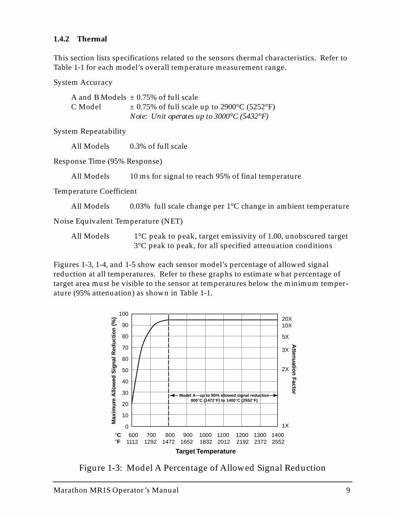
1.4.2 Thermal
This section lists specifications related to the sensors thermal characteristics. Refer toTable 1-1 for each model’s overall temperature measurement range.
System Accuracy
A and B Models ± 0.75% of full scaleC Model ± 0.75% of full scale up to 2900°C (5252°F)
Note: Unit operates up to 3000°C (5432°F)
System Repeatability
All Models 0.3% of full scale
Response Time (95% Response)
All Models 10 ms for signal to reach 95% of final temperature
Temperature Coefficient
All Models 0.03% full scale change per 1°C change in ambient temperature
Noise Equivalent Temperature (NET)
All Models 1°C peak to peak, target emissivity of 1.00, unobscured target 3°C peak to peak, for all specified attenuation conditions
Figures 1-3, 1-4, and 1-5 show each sensor model’s percentage of allowed signalreduction at all temperatures. Refer to these graphs to estimate what percentage oftarget area must be visible to the sensor at temperatures below the minimum temper-ature (95% attenuation) as shown in Table 1-1.
100
90
80
70
60
50
40
30
20
10
0
20X10X
5X
3X
2X
1X
Max
imu
m A
llow
ed S
ign
al R
edu
ctio
n (
%)
Target Temperature
°C°F
600 700 800 900 1000 1100 1200 1300 14001112 1292 1472 1652 1832 2012 2192 2372 2552
Atten
uatio
n Facto
r
Model A—up to 95% allowed signal reduction800°C (1472°F) to 1400°C (2552°F)
Figure 1-3: Model A Percentage of Allowed Signal Reduction
10 Marathon MR1S Operator’s Manual
100
90
80
70
60
50
40
30
20
10
0
20X10X
5X
3X
2X
1X
Max
imu
m A
llow
ed S
ign
al R
edu
ctio
n (
%)
Target Temperature
°C°F
700 800 900 1000 1100 1200 1300 1400 1500 1600 1700 18001292 1472 1652 1832 2012 2192 2372 2552 2732 2912 3092 3272
Atten
uatio
n Facto
r
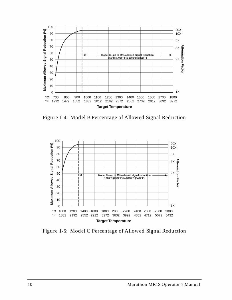
Model B—up to 95% allowed signal reduction950°C (1742°F) to 1800°C (3272°F)
Figure 1-4: Model B Percentage of Allowed Signal Reduction
Figure 1-5: Model C Percentage of Allowed Signal Reduction
100
90
80
70
60
50
40
30
20
10
0
20X10X
5X
3X
2X
1X
Max
imu
m A
llow
ed S
ign
al R
edu
ctio
n (
%)
Target Temperature
°C°F
1000 1200 1400 1600 18001832 2192 2552 2912 3272
2000 2200 2400 2600 28003632 3992 4352 4712 5072
30005432
Atten
uatio
n Facto
r
Model C—up to 95% allowed signal reduction1300°C (2372°F) to 3000°C (5432°F)
Marathon MR1S Operator’s Manual 11
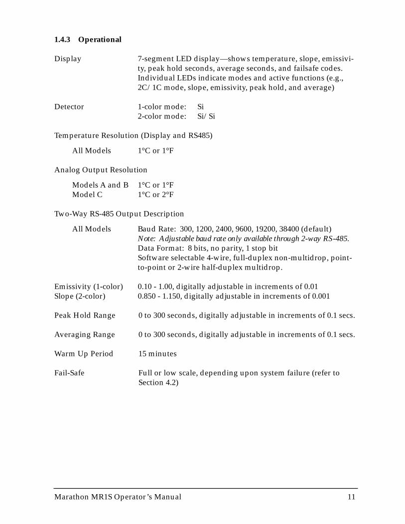
1.4.3 Operational
Display 7-segment LED display—shows temperature, slope, emissivi-ty, peak hold seconds, average seconds, and failsafe codes.Individual LEDs indicate modes and active functions (e.g.,2C/1C mode, slope, emissivity, peak hold, and average)
Detector 1-color mode: Si2-color mode: Si/Si
Temperature Resolution (Display and RS485)
All Models 1°C or 1°F
Analog Output Resolution
Models A and B 1°C or 1°FModel C 1°C or 2°F
Two-Way RS-485 Output Description
All Models Baud Rate: 300, 1200, 2400, 9600, 19200, 38400 (default)Note: Adjustable baud rate only available through 2-way RS-485.Data Format: 8 bits, no parity, 1 stop bitSoftware selectable 4-wire, full-duplex non-multidrop, point-to-point or 2-wire half-duplex multidrop.
Emissivity (1-color) 0.10 - 1.00, digitally adjustable in increments of 0.01Slope (2-color) 0.850 - 1.150, digitally adjustable in increments of 0.001
Peak Hold Range 0 to 300 seconds, digitally adjustable in increments of 0.1 secs.
Averaging Range 0 to 300 seconds, digitally adjustable in increments of 0.1 secs.
Warm Up Period 15 minutes
Fail-Safe Full or low scale, depending upon system failure (refer toSection 4.2)
12 Marathon MR1S Operator’s Manual
1.4.4 Electrical
Power 24 VDC, ± 20%, at 500 mA(Can tolerate up to 100 mV peak to peak of ripple)
Power Consumption maximum of 12 watts
Outputs 0-20 mA/4-20 mA, two-way RS485, relay control for failsafealarm or setpoint
Output Isolation 500 V AC or DC provided by Raytek supplied power supplyaccessory
Max CurrentLoop Impedance 500 ohm
DielectricWithstand Voltage 500 V
Relay Contacts Type: SPDT contact closure (software programmable to NOor NC)
Maximum rating: 48 V, 300 mA AC or DC
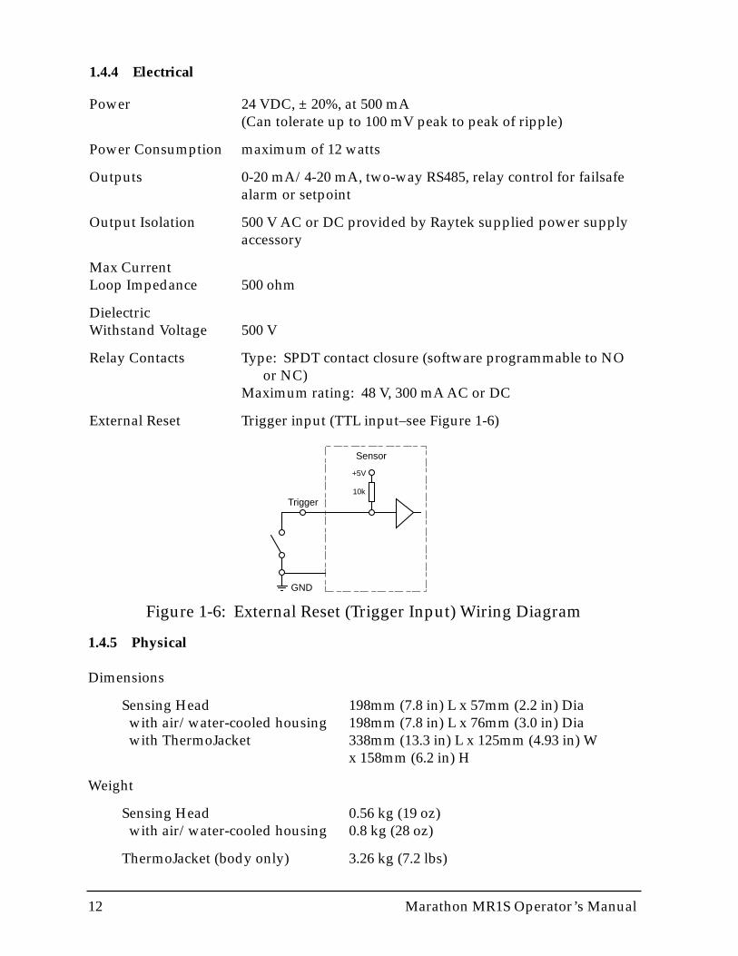
External Reset Trigger input (TTL input–see Figure 1-6)
Sensor
Trigger
GND
+5V
10k
Figure 1-6: External Reset (Trigger Input) Wiring Diagram
1.4.5 Physical
Dimensions
Sensing Head 198mm (7.8 in) L x 57mm (2.2 in) Dia with air/water-cooled housing 198mm (7.8 in) L x 76mm (3.0 in) Dia with ThermoJacket 338mm (13.3 in) L x 125mm (4.93 in) W
x 158mm (6.2 in) H
Weight
Sensing Head 0.56 kg (19 oz) with air/water-cooled housing 0.8 kg (28 oz)
ThermoJacket (body only) 3.26 kg (7.2 lbs)
Marathon MR1S Operator’s Manual 13
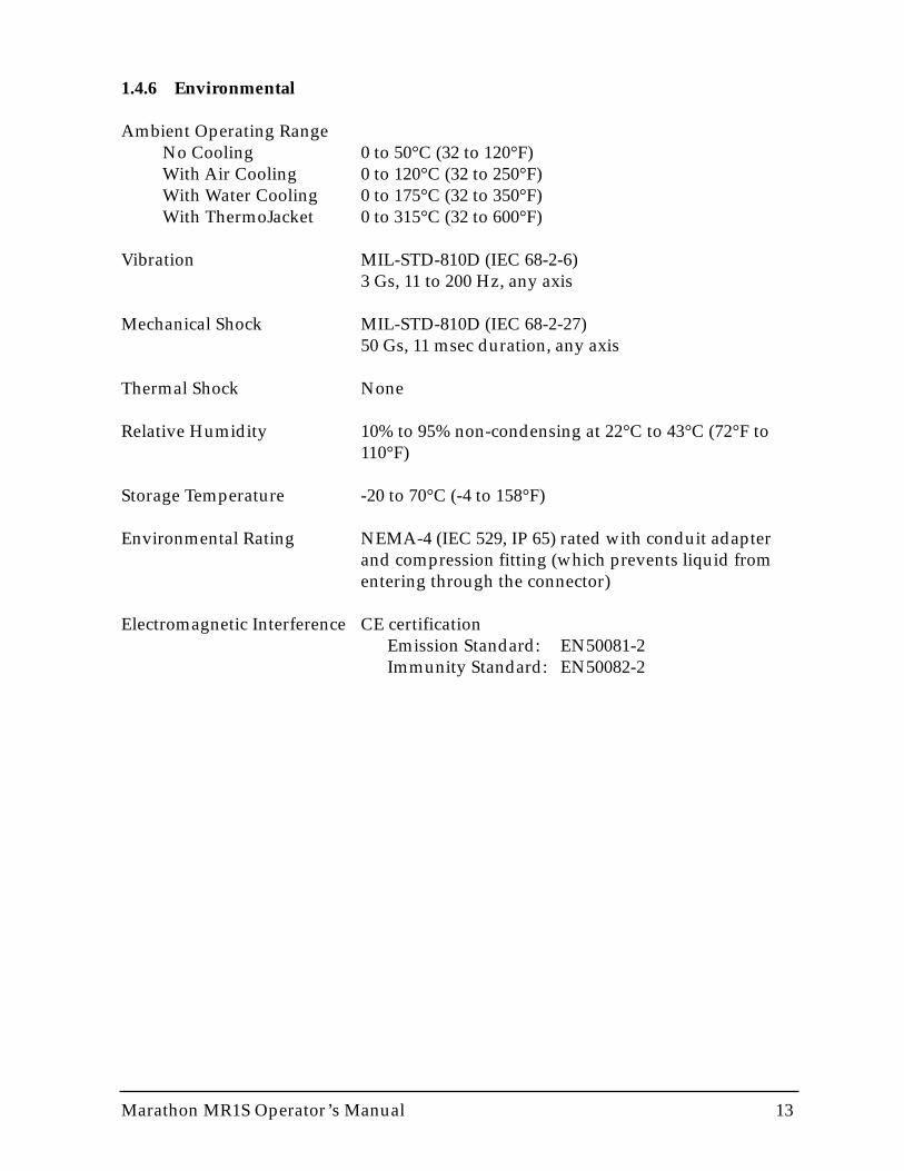
1.4.6 Environmental
Ambient Operating RangeNo Cooling 0 to 50°C (32 to 120°F)With Air Cooling 0 to 120°C (32 to 250°F)With Water Cooling 0 to 175°C (32 to 350°F)With ThermoJacket 0 to 315°C (32 to 600°F)
Vibration MIL-STD-810D (IEC 68-2-6)3 Gs, 11 to 200 Hz, any axis
Mechanical Shock MIL-STD-810D (IEC 68-2-27)50 Gs, 11 msec duration, any axis
Thermal Shock None
Relative Humidity 10% to 95% non-condensing at 22°C to 43°C (72°F to110°F)
Storage Temperature -20 to 70°C (-4 to 158°F)
Environmental Rating NEMA-4 (IEC 529, IP 65) rated with conduit adapterand compression fitting (which prevents liquid fromentering through the connector)
Electromagnetic Interference CE certificationEmission Standard: EN50081-2Immunity Standard: EN50082-2

14 Marathon MR1S Operator’s Manual
1.5 MECHANICAL
Mechanical specifications include measured drawings for the sensor and its acces-sories and options.
1.5.1 Sensors
The following illustrations show dimensions of a standard sensor (Figure 1-7), a sen-sor with the air/water-cooled housing option (Figure 1-8), and the adjustable bracket(supplied–Figure 1-9). Dimensions are listed for your installation convenience.
Figure 1-7: Sensing Head
Ø 57(2.24)
Ø 38(1.5)
Ø 24(.99)
Ø 24(0.95)FOR 3/4 EMT CONDUIT
35(1.38)
Ø 24(0.95)
1 1/2 – 20 UN–2A20(0.79)
48(1.9)
mm (inches)
197(7.76)
161(6.3) 155
(6.1)
20(.8)
16(.63)
Figure 1-8: Sensing Head with Air/Water-Cooled Housing Option
97(3.83)
20(0.79)
28(1.1)
3.3(0.13)
197(7.76)
158(6.22)
57(2.24)
56(2.2)
Ø 76(3)
12(0.47)12
(0.47)
1/8 – 27 NPT (2 PLCS)
Ø 24(0.95)
FOR 3/4 EMT CONDUIT
35(1.38)
Ø 24(0.95)
1 1/2 – 20 UN–2A20(0.79)
48(1.9)
23(0.9)
61(2.4)
mm (inches)
Ø 38(1.5)
Ø 24(.99)
16(.63)
48°119(4.75)94
(3.75)
56 REF(2.25)
Ø 37.5(1.5)
R 31(1.25)
120(4.8)
100(4)
102(4.063)
48°
77(3.063)
93(3.69)
7(.28)
102(4.063)
Ø 6(.25)
mm (inches)
Figure 1-9: Adjustable Bracket
Marathon MR1S Operator’s Manual 15
1.5.2 Accessories and Options
This section defines accessories and options, lists installation considerations, andshows the dimensions for each piece. Note that accessories can be purchased at anytime and added to the sensor(s). Options must be ordered with the unit(s). For pur-chasing information, contact your sales representative.
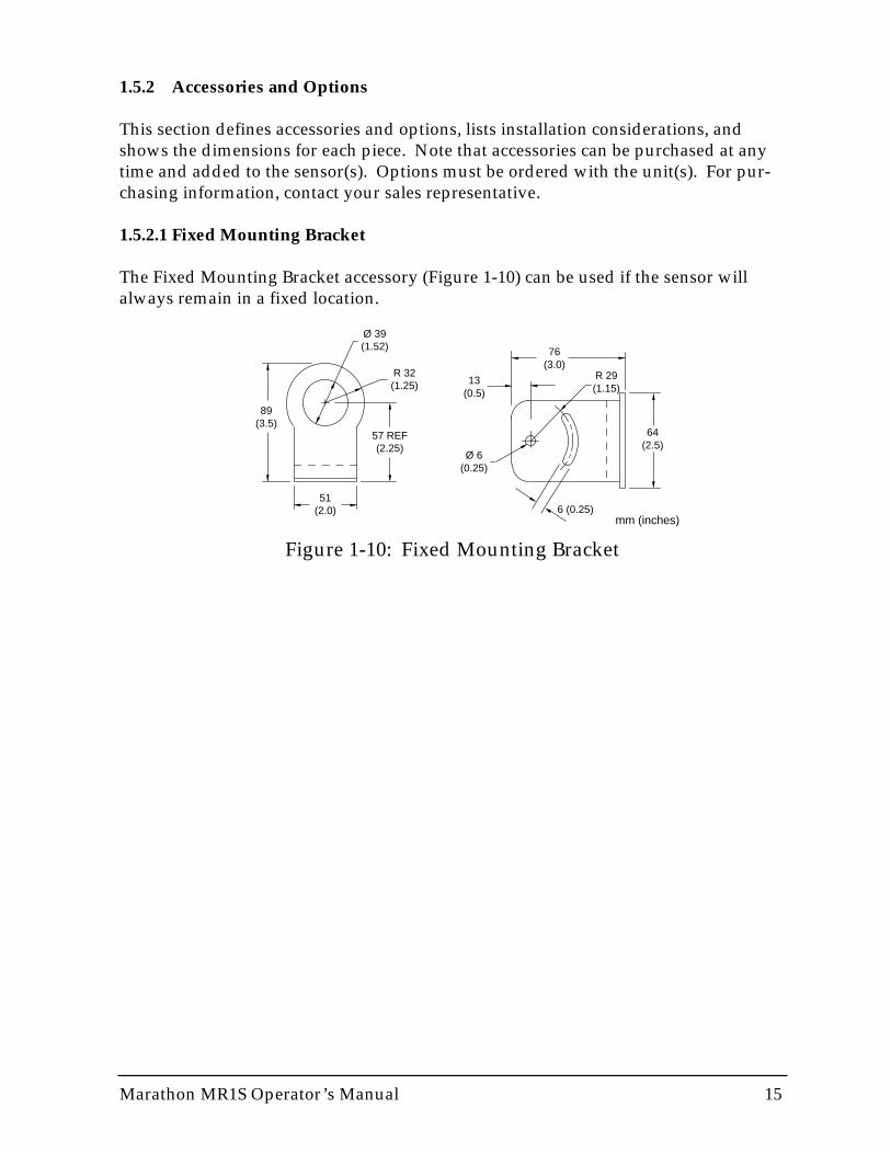
1.5.2.1 Fixed Mounting Bracket
The Fixed Mounting Bracket accessory (Figure 1-10) can be used if the sensor willalways remain in a fixed location.
51(2.0)
89(3.5)
57 REF(2.25)
Ø 39(1.52)
R 32(1.25)
76(3.0)
64(2.5)
R 29(1.15)
Ø 6(0.25)
13(0.5)
6 (0.25)mm (inches)
Figure 1-10: Fixed Mounting Bracket

16 Marathon MR1S Operator’s Manual
Ø 38(1.5)
Ø 63(2.5)
1/8 "27 NPT
38 (1.5)20 UN-2B
1.5"20 UN-2A
(approx. 38mm)
75(3)
22(.875)
25(1)
Figure 1-11: Air Purge Collar
Figure 1-12: Polarizing Filter
3/4 – 24 TPI (9 TPC)18(0.71)
21(0.83)
Ø 24(0.95) mm (inches)
1.5.2.2 Air Purge Collar
The Air Purge Collar accessory (Figure 1-11) is used to keep dust, moisture, airborneparticles, and vapors away from the lens. It can be installed before or after the bracket(see Figure 1-1, Accessories Overview). It must be screwed in fully. Air flows into the1/8” NPT fitting and out the front aperture. Air flow should be a maximum of (0.5 -1.5 liters/sec (1 - 3 cfm). Clean (filtered) or “instrument” air is recommended toavoid contaminants from settling on the lens. Do not use chilled air below 10°C(50°F).
IMPORTANTFocus the instrument before attaching the air purge collar.
1.5.2.3 Polarizing Filter
The Polarizing Filter (Figure 1-12) can be screwed into the viewing port to provide eyeprotection when sighting on bright, high temperature targets. The filter does notaffect measured energy. It is solely for viewing comfort. Rotate the outer portion ofthe filter until you achieve the desired visual attenuation.

Marathon MR1S Operator’s Manual 17
19(0.75)
1/4" NPTAIR PURGE IN
24(0.93)
94(3.7)
25(1)
1/4" UNC X .40 DP2 PLS EACH SIDEADJUSTABLE BRACKETMOUNTING POINTS
1/4" NPTCOOLANT OUT
1/4" NPTCOOLANT IN
130(5.1)
43(1.7)
130(5.1)
99(3.9)
168(6.6)
193(7.6)218
(8.6)337
(13.25)
92(3.63)
125(4.9)
3/4" NPT THRUELECTRICAL CONDUIT
25(1)
3 X Ø 0.31 THRU HOLEw/0.26 WIDE SLOT THRUw/Ø 0.575 CBORE X 0.05 DPON Ø 3.00 BC
Ø 76(3)
158(6.2)
118(4.65)
51(2)
125(4.9)
76(3)
360°ROTATION
30°PIVOT
Ø 92(3.63)
29(1.18)
305(12)
Ø 48(1.9)
1 1/2" NPT
13(0.5)
mm (inches)
Sighting Tube Mounting Flange
Blast Gate Adjustable Pipe Adapter
Adjustable Bracket
Stainless Steel Sighting Tubeand Ceramic Sighting Tube
Mounting Flange
90(3.5)
44(1.75)
Ø 7(0.275)3 plcs
Ø 76(3)
~220(8.75)closed
~115(4.5)
Ø 115(4.5)
1/8" NPT
~41(~1.625)
46(1.75)
46(1.75)
Ø 146(5.75)
1/4–20 THRU3 PLS
5/16–18–UNC3 PLS
10 (0.38) MIN3 PLS
Ø 92(3.63)
29(1.18)
Sighting tubemounting flange
Mounting flanges (2)
1/4–20 THRU3 PLS
Figure 1-13: ThermoJacket and Accessories
1.5.2.4 ThermoJacket and Accessories
The ThermoJacket accessory allows use of sensing heads in ambient temperatures upto 315°C (600°F). The ThermoJacket’s rugged cast aluminum housing completelyencloses the head and provides water cooling and air purging in one unit. Sensingheads can be easily installed or removed from the ThermoJacket housing in its mount-ed position. See the ThermoJacket Operator’s Manual for more information.
18 Marathon MR1S Operator’s Manual
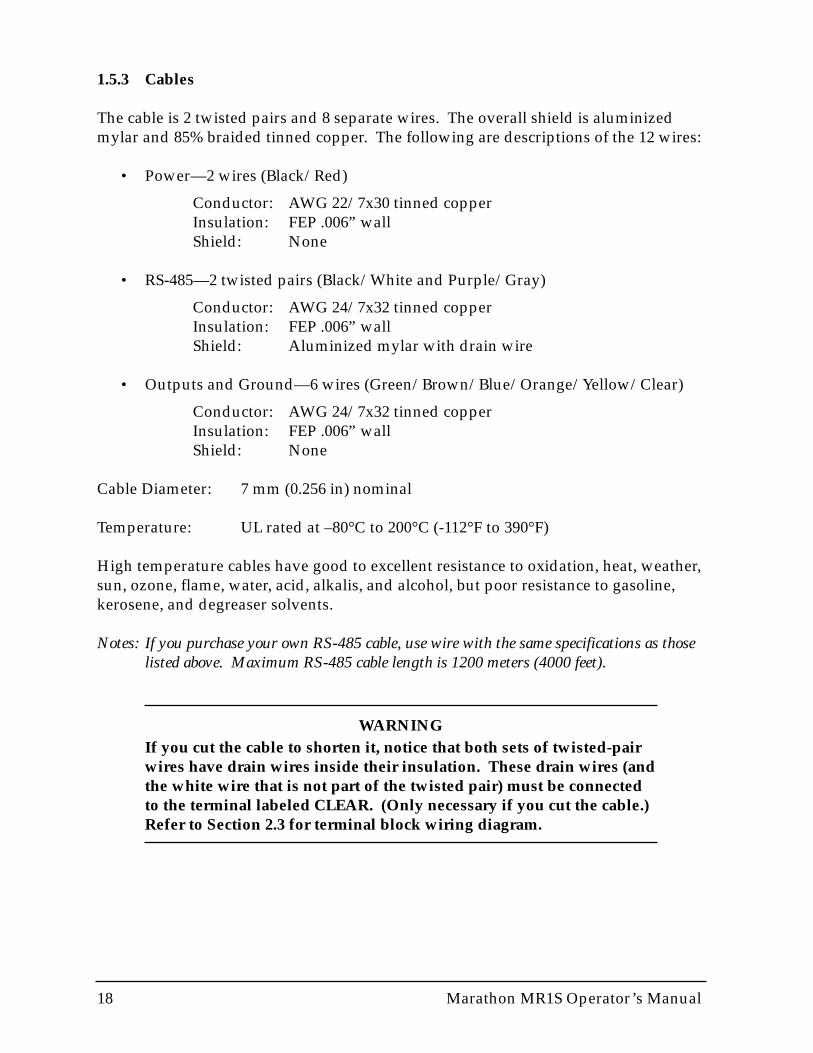
1.5.3 Cables
The cable is 2 twisted pairs and 8 separate wires. The overall shield is aluminizedmylar and 85% braided tinned copper. The following are descriptions of the 12 wires:
• Power—2 wires (Black/Red)
Conductor: AWG 22/7x30 tinned copperInsulation: FEP .006” wallShield: None
• RS-485—2 twisted pairs (Black/White and Purple/Gray)
Conductor: AWG 24/7x32 tinned copperInsulation: FEP .006” wallShield: Aluminized mylar with drain wire
• Outputs and Ground—6 wires (Green/Brown/Blue/Orange/Yellow/Clear)
Conductor: AWG 24/7x32 tinned copperInsulation: FEP .006” wallShield: None
Cable Diameter: 7 mm (0.256 in) nominal
Temperature: UL rated at –80°C to 200°C (-112°F to 390°F)
High temperature cables have good to excellent resistance to oxidation, heat, weather,sun, ozone, flame, water, acid, alkalis, and alcohol, but poor resistance to gasoline,kerosene, and degreaser solvents.
Notes: If you purchase your own RS-485 cable, use wire with the same specifications as thoselisted above. Maximum RS-485 cable length is 1200 meters (4000 feet).
WARNINGIf you cut the cable to shorten it, notice that both sets of twisted-pairwires have drain wires inside their insulation. These drain wires (andthe white wire that is not part of the twisted pair) must be connectedto the terminal labeled CLEAR. (Only necessary if you cut the cable.)Refer to Section 2.3 for terminal block wiring diagram.

Marathon MR1S Operator’s Manual 19
1.6 FACTORY DEFAULT VALUES
Table 1-2 lists the unit’s default values as it is shipped from the factory.
Table 1-2: Factory Defaults
PARAMETER AS SHIPPED FROM FACTORY (DEFAULTS) *
2-color mode, degrees C, TEMP display
1.00
0.0
0.0
38400 baud *
Low end of sensor temperature range **
High end of sensor temperature range **
Burst mode, Default string = UTSI
Controlled by unit, NO function (indicates failsafe alarms)
Controlled by unit, 4-20 mA
Unlocked
Standalone ***
4-wire ***
Display
Emissivity
AVG
PKH
Baud Rate
Temperature Setting for 4 mA
Temperature Setting for 20 mA
Serial Output Transmission Mode
Relay Output Control
Set Output Current
Lockout Switch Panel Access
Communications Mode
RS-485 Mode
Note that the default values can be loaded into the sensor by pressing the ▲ (up) and ▼ (down)buttons together for about 2 seconds or by 2-way instructions. The baud rate will not change from the last value when this is done. Factory defaults can be installed with a 2-way RS-485 command(#XF). Refer to Appendix D for explanations and examples of RS-485 commands.
These parameters can be adjusted both by a 2-way RS-485 command, which allows you to scale the high and low temperature points to suit your application.
Communications Mode and RS-485 Mode, like Baud Rate, are unchanged when the factorydefaults are restored.
*
**
***

20 Marathon MR1S Operator’s Manual

Marathon MR1S Operator’s Manual 21
Part 2 Non-multidrop Installation & Operation
This section explains the installation and operation of a Marathon infrared thermome-ter in a non-multidrop environment. If you are installing one or more sensors usingthese directions, you do not need Part 3. However, if your future plans include set-ting up a multidrop sensor network, consider using Part 3 instead of Part 2 so yourinitial installation will be multidrop ready.
Topics include...
• Preparation• Mechanical Installation• Electrical Installation• Operation

22 Marathon MR1S Operator’s Manual

Marathon MR1S Operator’s Manual 23
2.0 INSTALLATION
The installation process consists of the following:
• Preparation• Mechanical Installation• Electrical Installation
The most important part in the installation process is preparation. Please read Section2.1 thoroughly before proceeding with the mechanical and electrical installations.
2.1 PREPARATION
Sensor location, the configuration, and/or the number of sensors depend on theapplication. Before installing any sensors you need to be aware of the ambient tem-perature of the location, the atmospheric quality of the location (especially for 1-colortemperature measurements), and the possible electromagnetic interference in thatlocation. If you plan to use air purging and/or air or water cooling, you need to haveair and water connections available. Also, wiring and conduit runs must be consid-ered, including computer and controller wiring and connections, if used. The follow-ing subsections cover topics to consider before you install the sensor.
Note: All sensors, whether standard or with the air/water-cooled housing option, are suppliedwith an adjustable bracket and mounting nut. If necessary, the sensor can be mountedthrough a hole, or it can be mounted using a customer-supplied bracket or other acces-sories. (Refer to Part 1, Section 1.1 and 1.2, for an overview of the available accessoriesand options.)
2.1.1 Ambient Temperature
The sensing head is designed to operate in ambient temperatures between 0°C (32°F)and 50°C (120°F). The internal ambient temperature can vary from 10°C (50°F) to68°C (154°F). Internal temperatures outside this range will cause a failsafe error. Inambient conditions above 50°C (120°F), an optional air/water-cooled housing is avail-able to extend the operating range to 120°C (250°F) with air cooling, or 175°C (350°F)with water cooling. When using the water cooled housing, it is strongly recommend-ed to also use the air purge collar to avoid condensation on the lens. In ambient con-ditions up to 315°C (600°F), the ThermoJacket accessory should be used.
When using air or water cooling and air purging, make sure air and water suppliesare installed before proceeding with the sensor installation.
Water and air temperatures for cooling should be 15-30°C (60-86°F) for best perfor-mance. Chilled water or air below 10°C (50°F) is not recommended. For air purgingor air cooling, clean (filtered) or “instrument” air is recommended.

24 Marathon MR1S Operator’s Manual
2.1.2 Atmospheric Quality
Smoke, fumes, dust, and other contaminants in the air, as well as a dirty lens are gen-erally not a problem when using the 2-color mode (as long as the attenuation is equalin both spectral bands). However, if the lens gets too dirty, it cannot detect enoughinfrared energy to measure accurately, and the instrument will indicate a failure (seeSection 4.2). It is good practice to always keep the lens clean. The Air Purge Collarhelps keep contaminants from building up on the lens.
If you use air purging, make sure an air supply is installed before proceeding with thesensor installation.
2.1.3 Electrical Interference
To minimize electrical or electromagnetic interference or “noise,” be aware of the fol-lowing:
• Mount the sensor as far away as possible from potential sources of electricalinterference such as motorized equipment producing large step load changes.
• Use shielded wire for all input and output connections.
• Make sure the shield wire in the sensor cable is earth grounded.
• For additional protection, use conduit for the external connections. Solid con-duit is better than flexible conduit in high noise environments.
• Do not run AC power for other equipment in the same conduit.

Marathon MR1S Operator’s Manual 25
2.1.4 Sensor Location
The Standard Focus sensor can be focused from 600 mm (24 in) to infinity, and theClose Focus sensor can be focused from 300 mm (12 in) to 600 mm (24 in), so sensorplacement can be varied to suit the application. Figure 2-1 shows sensor placementand the various conditions where 2-color temperature measurements can be taken.Note, however, that if the field of view degrades beyond 95%, accuracy also degrades.
IMPORTANTWhen installing the sensor, check for any high-intensity dischargelamps or heaters that may be in the field of view (either backgroundor reflected on a shiny target). Reflected heat sources can cause a 2-color sensor to give erroneous readings.
Figure 2-1: 2-Color Sensor Placement
Minimum distancesensor to target600 mm (24 in)
Emittedenergy
Sighting hole smallerthan sensor's field of view
Emittedenergy
Emittedenergy
Smoke, steam, dust,gas in atmosphere
Emittedenergy
Target smallerthan field of view
and/or moves or vibrates in and out of field of view (e.g., wire)
Dirty lens or dirty sighting window
2-Color temperature measurements can be taken, accurately and repeatedly, in the following conditions:
26 Marathon MR1S Operator’s Manual
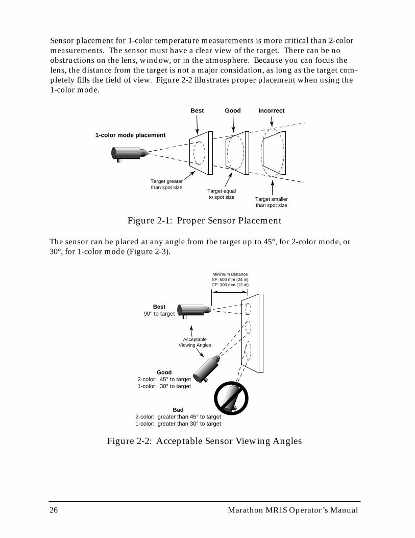
Sensor placement for 1-color temperature measurements is more critical than 2-colormeasurements. The sensor must have a clear view of the target. There can be noobstructions on the lens, window, or in the atmosphere. Because you can focus thelens, the distance from the target is not a major considation, as long as the target com-pletely fills the field of view. Figure 2-2 illustrates proper placement when using the1-color mode.
Best Good Incorrect
Target equalto spot size Target smaller
than spot size
Target greaterthan spot size
1-color mode placement
Figure 2-1: Proper Sensor Placement
The sensor can be placed at any angle from the target up to 45°, for 2-color mode, or30°, for 1-color mode (Figure 2-3).
Best90° to target
Good2-color: 45° to target1-color: 30° to target
Bad2-color: greater than 45° to target1-color: greater than 30° to target
AcceptableViewing Angles
Minimum DistanceSF: 600 mm (24 in)CF: 300 mm (12 in)
Figure 2-2: Acceptable Sensor Viewing Angles
Marathon MR1S Operator’s Manual 27
2.2 MECHANICAL INSTALLATION
After all preparations are complete, you can install the sensor.
2.2.1 Mounting the Sensor
How you anchor the sensor depends on the type of surface and the type of bracketyou are using. As noted before, all sensors, whether standard or with the air/water-cooled housing option, are supplied with an adjustable bracket and mounting nut.You can also mount the sensor through a hole, on a bracket of your own design, or onone of the other available mounting accessories (refer to Part 1). If you are installingthe sensor in a ThermoJacket accessory, you should use the appropriate mountingdevice. (Refer to Part 1 for an overview of ThermoJacket accessories.) If you do nothave the focusing tool accessory, the sensor must be focused before mounting inside aThermoJacket or before attaching an air purge collar.
NOTICEIf you are installing two or more sensors in a multi-drop configura-tion, or if you plan to add to or more sensors at a later date, refer toPart 3 for information on multi-drop installations.
2.2.2 Aiming and Focusing
Once you have the sensor in place, you need to aim and focus it on the target. To aimand focus the sensor, complete the following:
1. Loosen the nuts or bolts of the mounting base. (This can be either a factory-sup-plied accessory or customer-supplied base.)
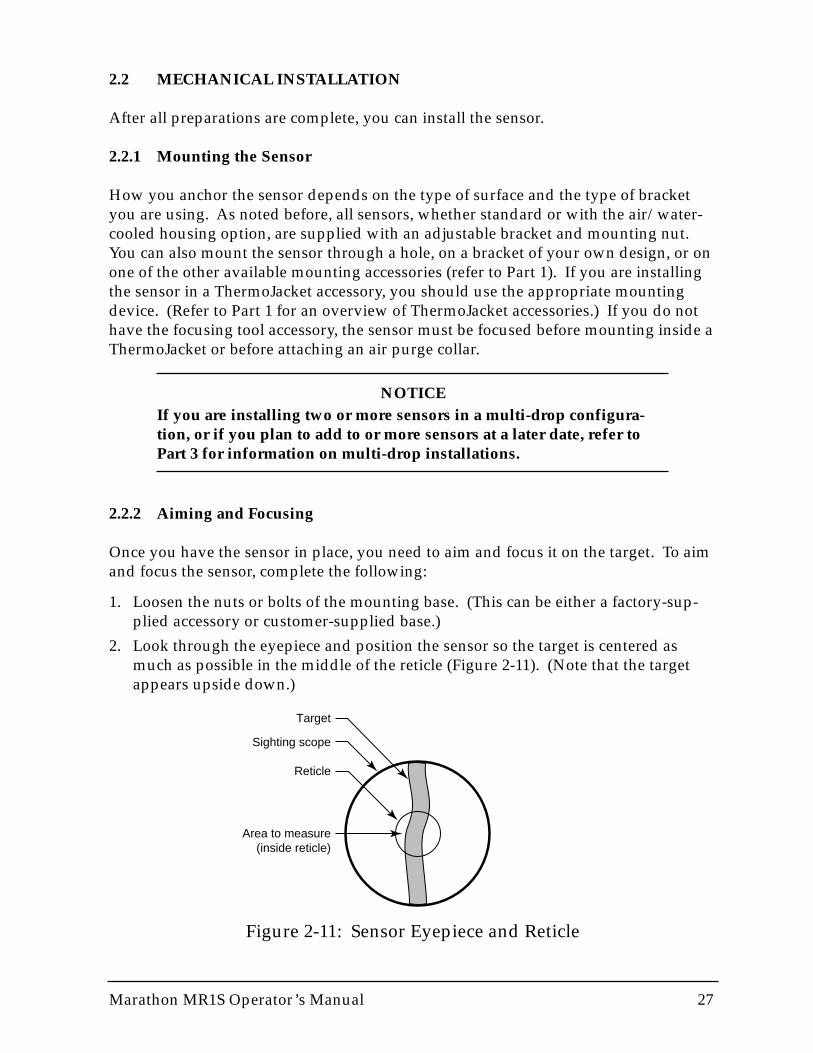
2. Look through the eyepiece and position the sensor so the target is centered asmuch as possible in the middle of the reticle (Figure 2-11). (Note that the targetappears upside down.)
Figure 2-11: Sensor Eyepiece and Reticle
Target
Sighting scope
Reticle
Area to measure(inside reticle)
28 Marathon MR1S Operator’s Manual
3. Turn the lens holder clockwise or counter-clockwise until the target is in focus.
You can tell the lens is focused correctly by moving your eye from side to sidewhile looking through the eyepiece. The target should not move with respect tothe reticle. If it does, keep adjusting the focus until no apparent motion isobserved.
4. Check once more to make sure the target is still centered, and secure the mountingbase. Focusing is complete.
2.3 ELECTRICAL INSTALLATION
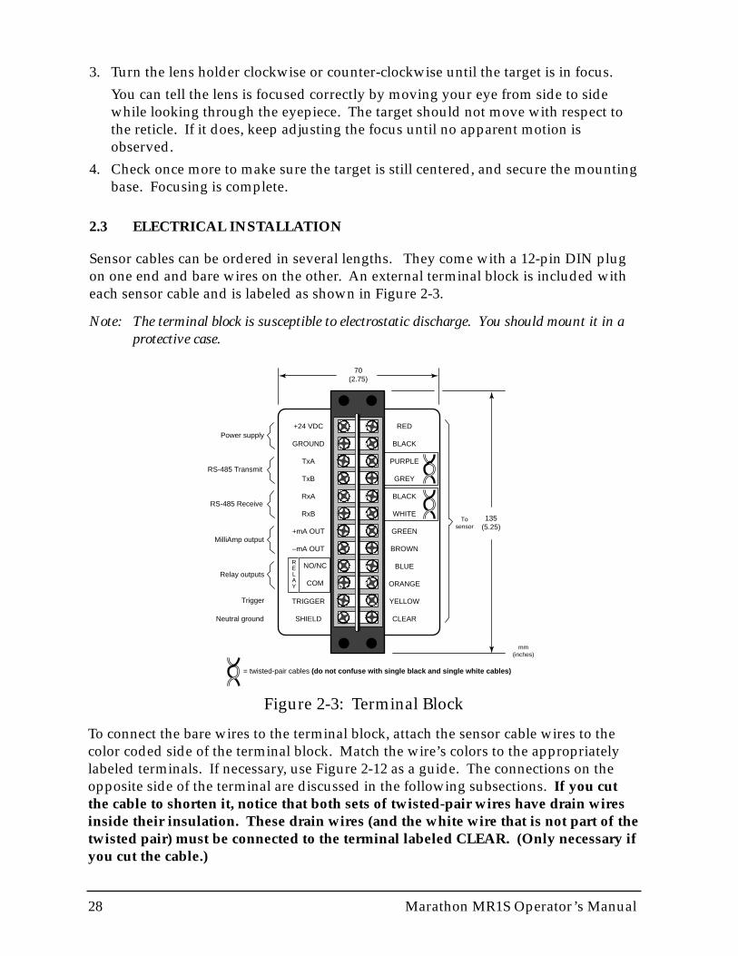
Sensor cables can be ordered in several lengths. They come with a 12-pin DIN plugon one end and bare wires on the other. An external terminal block is included witheach sensor cable and is labeled as shown in Figure 2-3.
Note: The terminal block is susceptible to electrostatic discharge. You should mount it in aprotective case.
Figure 2-3: Terminal Block
+24 VDC
GROUND
TxA
TxB
RxA
RxB
+mA OUT
–mA OUT
TRIGGER
SHIELD
RED
BLACK
PURPLE
GREY
BLACK
WHITE
GREEN
BROWN
BLUE
ORANGE
YELLOW
CLEAR
Power supply
RS-485 Transmit
RS-485 Receive
MilliAmp output
Relay outputs
Neutral ground
Trigger
= twisted-pair cables (do not confuse with single black and single white cables)
To sensor
RELAY
NO/NC
COM
135(5.25)
70(2.75)
mm(inches)
To connect the bare wires to the terminal block, attach the sensor cable wires to thecolor coded side of the terminal block. Match the wire’s colors to the appropriatelylabeled terminals. If necessary, use Figure 2-12 as a guide. The connections on theopposite side of the terminal are discussed in the following subsections. If you cutthe cable to shorten it, notice that both sets of twisted-pair wires have drain wiresinside their insulation. These drain wires (and the white wire that is not part of thetwisted pair) must be connected to the terminal labeled CLEAR. (Only necessary ifyou cut the cable.)
Marathon MR1S Operator’s Manual 29
WARNINGIncorrect wiring can damage the sensor and void the warranty. Beforeapplying power, make sure all connections are correct and secure.
Note: When using conduit for the cable, and when it has a compression fitting installed onthe conduit connection, the sensor head is rated NEMA-4 (IEC 529, IP 65).
IMPORTANTThe sensor cable may be shortened but not lengthened without theappropriate terminal block accessory. Longer cables are availablefrom the factory. Limit power cables to 60 meters (200 feet) or less.RS-485 cables can be extended up to 1200 meters (4000 feet).
Avoid installing the sensor cable in noisy electrical environmentssuch as around electrical motors, switch gear, or induction heaters. Inthese environments, it is recommended to install the cable in conduit.Note that the sensor head is designed to fit conduit directly.
2.3.1 Power
Connections from a 24 VDC (250 mA or higher) power supply attach to the first twoterminals on the terminal strip (as shown in Figure 2-3).
IMPORTANTIsolation is provided only when used with the appropriate Rayteksupplied power supply accessory.
30 Marathon MR1S Operator’s Manual
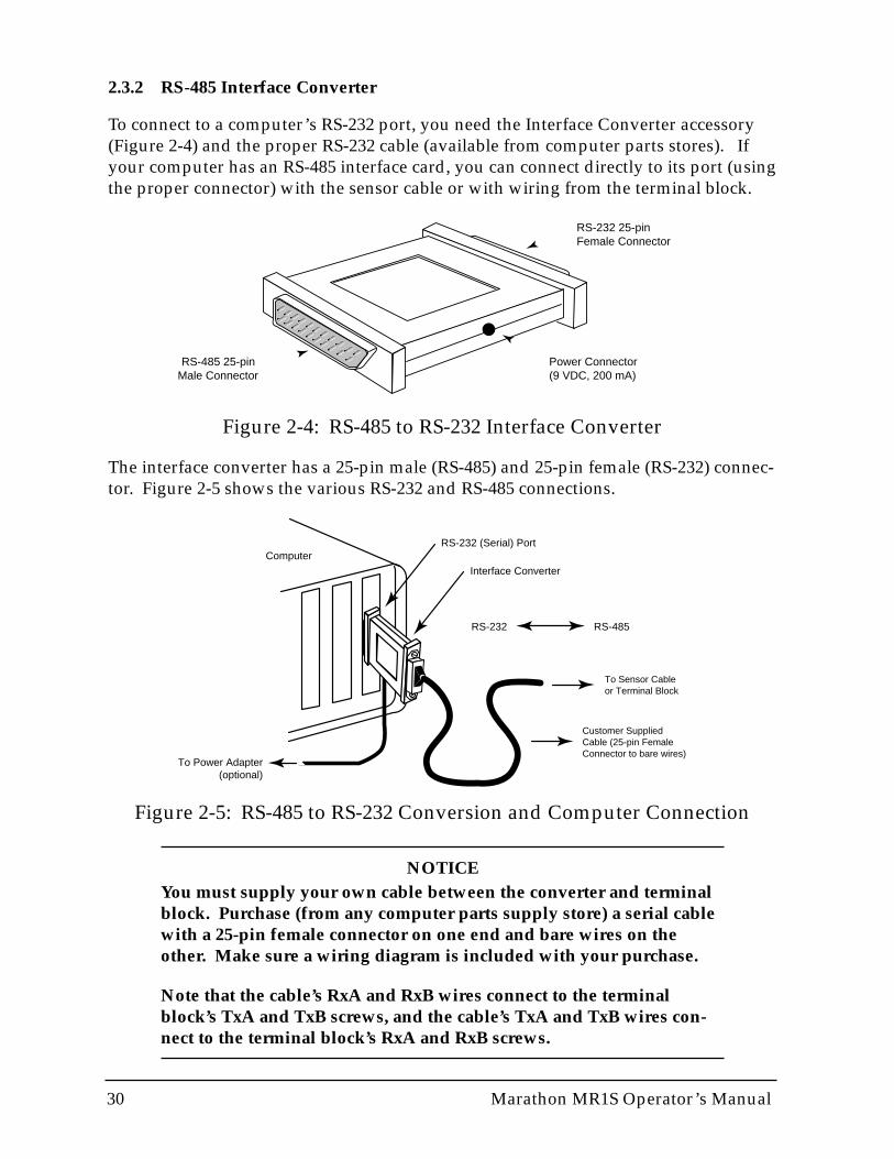
Figure 2-5: RS-485 to RS-232 Conversion and Computer Connection
Interface ConverterComputer
To Power Adapter(optional)
RS-232 (Serial) Port
RS-232 RS-485
To Sensor Cable or Terminal Block
Customer SuppliedCable (25-pin FemaleConnector to bare wires)
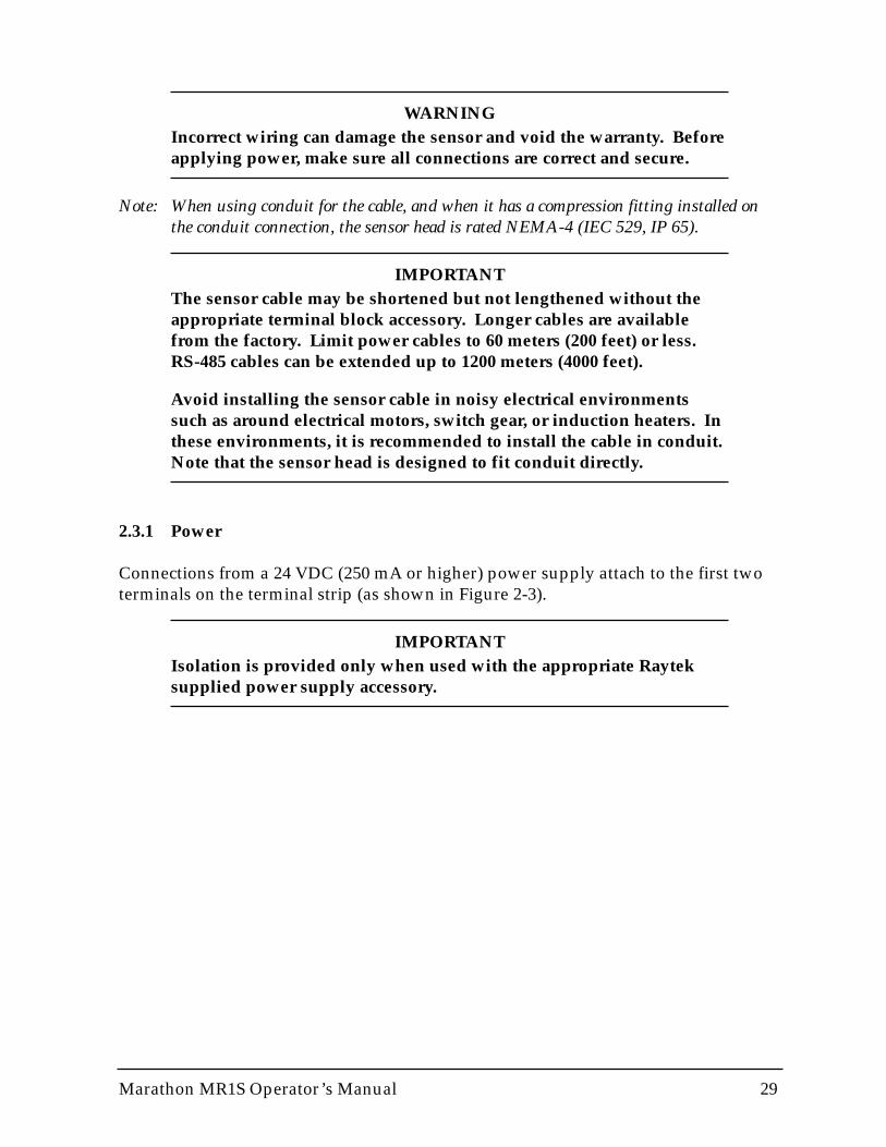
Figure 2-4: RS-485 to RS-232 Interface Converter
Power Connector(9 VDC, 200 mA)
RS-232 25-pin Female Connector
RS-485 25-pin Male Connector
2.3.2 RS-485 Interface Converter
To connect to a computer’s RS-232 port, you need the Interface Converter accessory(Figure 2-4) and the proper RS-232 cable (available from computer parts stores). Ifyour computer has an RS-485 interface card, you can connect directly to its port (usingthe proper connector) with the sensor cable or with wiring from the terminal block.
The interface converter has a 25-pin male (RS-485) and 25-pin female (RS-232) connec-tor. Figure 2-5 shows the various RS-232 and RS-485 connections.
NOTICEYou must supply your own cable between the converter and terminalblock. Purchase (from any computer parts supply store) a serial cablewith a 25-pin female connector on one end and bare wires on theother. Make sure a wiring diagram is included with your purchase.
Note that the cable’s RxA and RxB wires connect to the terminalblock’s TxA and TxB screws, and the cable’s TxA and TxB wires con-nect to the terminal block’s RxA and RxB screws.

Marathon MR1S Operator’s Manual 31
Note: Personal computers can have up to 4 serial ports (RS-232 connections). These are list-ed as COM1, COM2, COM3, and COM4. Usually COM1 and COM2 are the onlyphysical connections on the back of the computer.
Connect the interface converter to an available COM port on your computer. If yourcomputer has a 9-pin serial connector, use a 25-pin to 9-pin adapter between the inter-face converter and the computer.
IMPORTANTOn older computers the COM1 port is used by a pointing device(mouse, trackball, etc.), and sometimes the COM2 port is connected toan external modem or fax/modem (an internal modem can also be setto use COM2). It is possible for two devices to share an interrupt(COM1/COM3 or COM2/COM4); however, they cannot be used at thesame time or your system might “crash.” You can connect the RS-232cable to the same port as, for instance, your modem, but you need tomake sure the modem is inactive while you use the sensor.
The RS-485 output is as follows:
Baud Rate: 300, 1200, 2400, 9600, 19200, 38400 (default)Note: Adjustable baud rate only available through 2-way RS-485.Data Format: 8 bits, no parity, 1 stop bitFour-wire full duplex, point-to-point
For a full description of the RS-485 output string, see Appendix B.
WARNINGIf you are using the converter’s optional power adapter, note the fol-lowing: After connecting the serial cables, attach the adapter plug intothe converter BEFORE plugging the AC adapter into an AC outlet.

32 Marathon MR1S Operator’s Manual
2.3.3 Milliamp Output
The milliamp output is an analog output you can connect directly to a chart recorderor other recording device.
The analog output resolution for A and B models is 1°C or 1°F, C model is 1 °C or 2°F.
The analog output corresponds to either the 2-color or 1-color readings on the display.
Note: The mA output can be forced to a specific value, underrange, or overrange with a 2-way RS-485 command. See Appendix B for details. This feature is useful for testingor calibrating connected equipment.
2.3.4 Relay Outputs
The relay output is used as an alarm for failsafe conditions only. (Refer to Section 4.2for failsafe information.) This corresponds to the currently displayed temperature onthe LED display (2C or 1C).
Note: Since the way you use the relay outputs depends on the application, check with yoursales representative for the best way to use this feature.
Connections can be made to the terminal strip for Normally Open (Relay NO) orNormally Closed (Relay NC). One terminal is common for both (Relay COM).
Note: The relay can be set to either NO (Normally Open) or NC (Normally Closed)with a 2-way RS-485 command depending on compatibility requirements of connect-ed equipment. The relay can be forced on or off via 2-way RS-485 for testing connect-ed equipment. See Appendix B for details.
Marathon MR1S Operator’s Manual 33
2.4 OPERATION
Once you have your sensor(s) positioned and connected properly, the system is readyfor continuous operation. Operation is accomplished either through the back panel orthrough controlling software. A Graphic Setup and Display program is supplied withyour sensor and is covered in Part 4. You can also create custom programs using thecommunications protocols listed in Appendix B.
IMPORTANTMake sure air, water, power, and computer connections are secure.
Avoid taking temperature measurements in bright sunlight. Also, beaware targets with low temperatures (below the sensor’s range) andlow emissivities may not register correctly.
2.4.1 THE CONTROL PANEL
The sensor is equipped with a control panel, which has setting/controlling buttonsand an LED display. The panel is used primarily for setting up the instrument and iscovered over during normal use. Besides displaying the current temperature, theLED can display slope (2-color) or emissivity (1-color), the peak hold setting, and theaverage temperature.
The control panel is protected by the supplied end cap. The sighting hole in the endcap is threaded to accept the polarizing filter accessory (used for sighting/focusing onvery bright targets). An end cap with a larger window, which allows all control panelLEDs to be visible, is available as an option. (You cannot use the polarizing filter withthis option.)
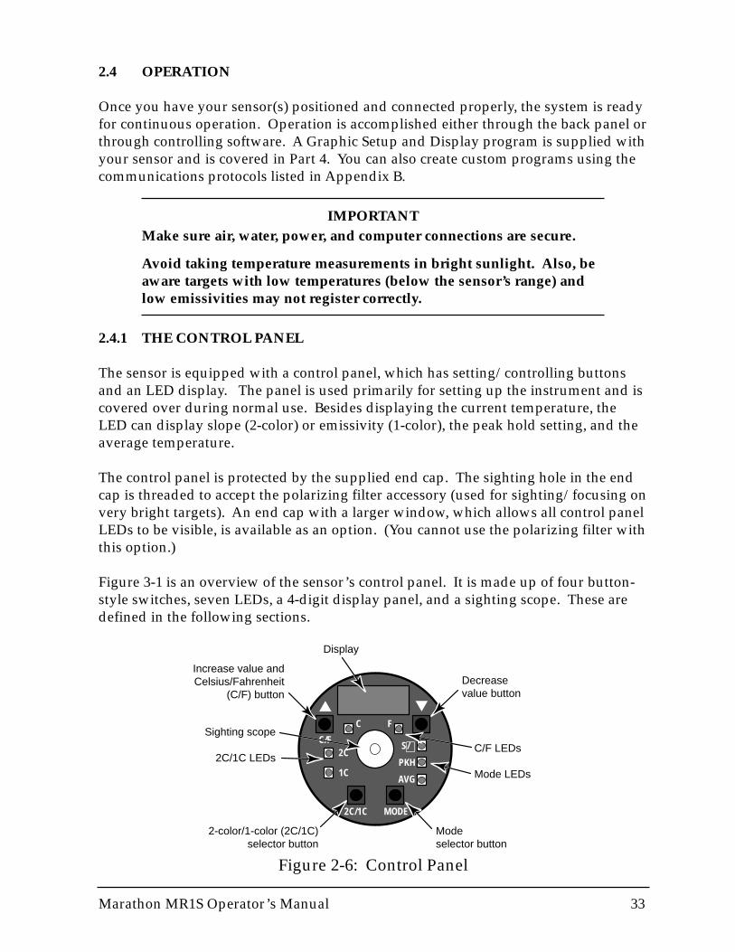
Figure 3-1 is an overview of the sensor’s control panel. It is made up of four button-style switches, seven LEDs, a 4-digit display panel, and a sighting scope. These aredefined in the following sections.
Figure 2-6: Control Panel
2C/1C MODE
C/F
C F
2C
1C
S/
PKH
AVG
▼▲
∋
Decreasevalue button
Mode selector button
Increase value and Celsius/Fahrenheit
(C/F) button
2-color/1-color (2C/1C) selector button
Sighting scope
2C/1C LEDsC/F LEDs
Mode LEDs
Display
34 Marathon MR1S Operator’s Manual
2.4.2 SET-UP
To begin setting up the sensor, first make sure all connections are secure, then turn onthe power supply. Allow the sensor to warm up for 15 minutes before making con-trol panel adjustments. (You can also set up remotely through the 2-way RS-485 con-nection. Refer to Appendix B.)
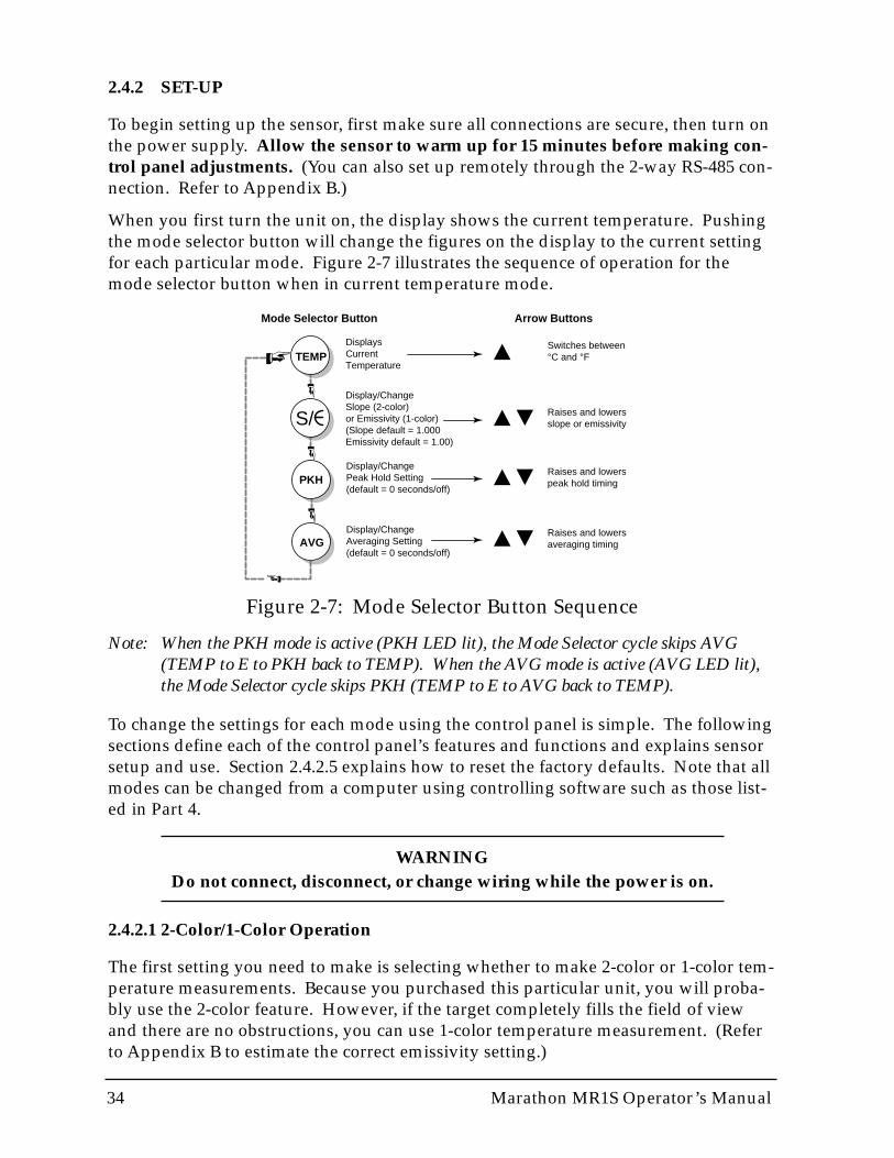
When you first turn the unit on, the display shows the current temperature. Pushingthe mode selector button will change the figures on the display to the current settingfor each particular mode. Figure 2-7 illustrates the sequence of operation for themode selector button when in current temperature mode.
Figure 2-7: Mode Selector Button Sequence
Note: When the PKH mode is active (PKH LED lit), the Mode Selector cycle skips AVG(TEMP to E to PKH back to TEMP). When the AVG mode is active (AVG LED lit),the Mode Selector cycle skips PKH (TEMP to E to AVG back to TEMP).
To change the settings for each mode using the control panel is simple. The followingsections define each of the control panel’s features and functions and explains sensorsetup and use. Section 2.4.2.5 explains how to reset the factory defaults. Note that allmodes can be changed from a computer using controlling software such as those list-ed in Part 4.
WARNINGDo not connect, disconnect, or change wiring while the power is on.
2.4.2.1 2-Color/1-Color Operation
The first setting you need to make is selecting whether to make 2-color or 1-color tem-perature measurements. Because you purchased this particular unit, you will proba-bly use the 2-color feature. However, if the target completely fills the field of viewand there are no obstructions, you can use 1-color temperature measurement. (Referto Appendix B to estimate the correct emissivity setting.)
TEMP
PKH
AVG
Displays Current Temperature
Switches between°C and °F
Raises and lowersslope or emissivity
Display/Change Slope (2-color)or Emissivity (1-color)(Slope default = 1.000Emissivity default = 1.00)
Display/Change Peak Hold Setting(default = 0 seconds/off)
Display/Change Averaging Setting(default = 0 seconds/off)
S/
Raises and lowerspeak hold timing
Raises and lowersaveraging timing
Mode Selector Button Arrow Buttons
Marathon MR1S Operator’s Manual 35
2C/1C Switch
To switch between 2-color and 1-color temperature measurement push the 2C/1Cselector button. A lit LED indicates the active measurement method. (Figure 3-1shows the location of the 2C/1C selector.)
Note: Switching affects the LED display and analog out but not the RS-485 out. Switchingbetween 1C and 2C can also be done with a 2-way RS-485 command. See Appendix Bfor details.
Lockout Mode
The sensor has a remote locking feature that keeps the unit from being accidentallychanged from the control panel. This lockout mode denies access to all the switcheson the control panel. It is available through the RS-485 connection and can beunlocked only by a command from the remote computer. See Appendix B for details.
2.4.2.2 Modes
Pressing the mode selector button (Figure 3-1) cycles you through the four operatingmodes (as shown in Figure 3-2): temperature display mode, Slope/Emissivity displayand adjustment mode, Peak Hold output display and adjustment mode, Average out-put display and adjustment mode, and back to the temperature display mode.
Temperature
The temperature display can be set for either °C or °F by pressing the C/F selectorbutton (▲–up arrow), which also doubles as the Increase Value button for the othermodes. The Decrease Value (▼–down arrow) button is inactive in this mode. A litLED shows you whether the measured temperature is in °C or °F. Note that this set-ting influences the RS-485 output for both target and internal temperatures.
Slope/Emissivity
The slope is an adjustment that compensates for the differences in the emissivity ofthe two spectral ranges. The emissivity is a calculated ratio of infrared energy emittedby an object to the energy emitted by a blackbody at the same temperature (a perfectradiator has an emissivity of 1.00). The slope is preset at the factory at 1.000, and theemissivity is preset at 1.00. For information on determining an unknown emissivity,and for sample emissivities, refer to Appendix B.

36 Marathon MR1S Operator’s Manual
You can set the unit up for either 2-color or 1-color measurements. The 2C/1C selec-tor button on the control panel switches between the two functions. One of the redLEDs above the button, labeled 2C and 1C, will show what function is active.
For 2-color measurements—You need to set the slope for the material being mea-sured. To set the slope, do the following:
1. Press the Mode button until the LED is lit.
The current slope value shows on the display.
2. Press the ▲▲ or ▼▼ (UP or DOWN) button to change the value.
3. Press the Mode button several times until the temperature LED indicator is lit.
The displayed temperature will now be based on the new slope value.
IMPORTANTThe following slope settings are approximate and will vary depend-ing on the metal alloy and surface finish, as well as the application.These are supplied here as examples.
Set the slope to approximately 1.000 for measuring the following metals with oxidizedsurfaces:
• Cobalt • Stainless Steel • Nickel• Iron • Steel
Set the slope to approximately 1.060 for measuring the following metals with smooth,clean, unoxidized surfaces:
• Cobalt • Rhodium • Platinum• Iron • Stainless Steel • Tungsten• Molybdenum • Steel• Nickel • Tantalum
Molten iron also has an approximate slope setting of 1.060.
Unknown Slope—To measure the temperature of objects or materials that are not list-ed above, you will have to set the slope by doing the following (make sure the 2CLED is lit):
1. Take the temperature of the target’s surface.
Use a reliable contact or probe thermometer. If you have to measure several areason the target, use the average of the temperatures for the following steps.
2. Aim the unit at the target.
3. Press the Mode button until the LED is lit.
The current slope value shows on the display.
4. Press the ▲▲ or ▼▼ (UP or DOWN) button to change the value.
S/
∋S/
∋
Marathon MR1S Operator’s Manual 37
5. Press the Mode button several times until the C or F LED indicator is lit.
Compare the displayed temperature to that of the contact or probe thermometer’s.If they are not the same, repeat steps 3 through 5 until they are.
Emissivity—When using the 1-color feature you have to set the emissivity, if neces-sary. The emissivity is preset at the factory at 1.00. If this is acceptable for the type ofsurface you are measuring, no adjustment is necessary. However, if you are unsure ofthe target’s emissivity, refer to Appendix B, which lists the emissivities of many met-als and non-metals. If the material you want to measure is not listed, Appendix B alsoshows how to determine an unknown emissivity.
To change the unit’s emissivity setting, complete the following (make sure the 1C LEDis lit):
1. Press the Mode button until the LED is lit.
The current emissivity value shows on the display.
2. Press the ▲▲ or ▼▼ (UP or DOWN) button to change the value.
3. Press the Mode button several times until the temperature LED is lit.
The displayed temperature will now be based on the new emissivity value.
Note: Slope and emissivity can also be adjusted with a 2-way RS-485 command. SeeAppendix A for details.
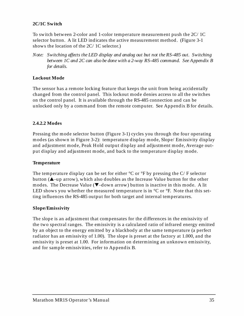
Peak Hold (PKH)
Peak Hold can be useful when a peak temperature reading is desired. For example,use Peak Hold when the background temperature between discrete targets is less thanthat of the target. Figure 2-8 illustrates the Peak Hold output signal.
S/
∋
1000° 750° 1250° 1000°
Hot objects moving ona production line
Standard output signal
Peak hold output signal
Peak hold duration
Figure 2-8: Peak Hold Output Signal Example

38 Marathon MR1S Operator’s Manual
When you activate Peak Hold, the instrument monitors the maximum temperatureseen over a predetermined time interval (duration). Should the unit measure a tem-perature higher than the one it is presently displaying, it immediately updates the dis-play and starts a new time interval. On the other hand, should it see no temperatureabove the one presently displayed, it will hold this value until the duration expires, atwhich time it will update to a new value equal to the highest temperature seen at thetime the interval expired. If the unit measures an intermediate temperature beforemeasuring ambient, and if the last object has passed, the unit will display and outputthe intermediate value for one more duration before ambient is finally displayed.Figure 2-8 illustrates this function. This algorithm prevents large changes in output, adesirable feature for controller applications.
To set and activate Peak Hold, do the following:
1. Press the Mode button until the PKH LED is lit.
2. Press the ▲▲ (UP) button to both set and activate.
The display reads in 0.1 seconds. Set Peak Hold from 0 to 299.9 seconds. If PeakHold is set to 300.0 seconds, a hardware reset is needed to trigger another reading.
3. Press the Mode button until the C or F LED is lit.
If Peak Hold has been activated, the Peak LED will stay lit.
Once Peak Hold is set above 0, it automatically activates. Note that Averaging (AVG)cannot be used concurrently. To deactivate Peak Hold, push the MODE button untilonly the PKH LED indicator is lit and reset to 0 by pushing the ▼ (DOWN) button.
Note: Peak Hold can also be adjusted with a 2-way RS-485 command. See Appendix B fordetails.
Marathon MR1S Operator’s Manual 39
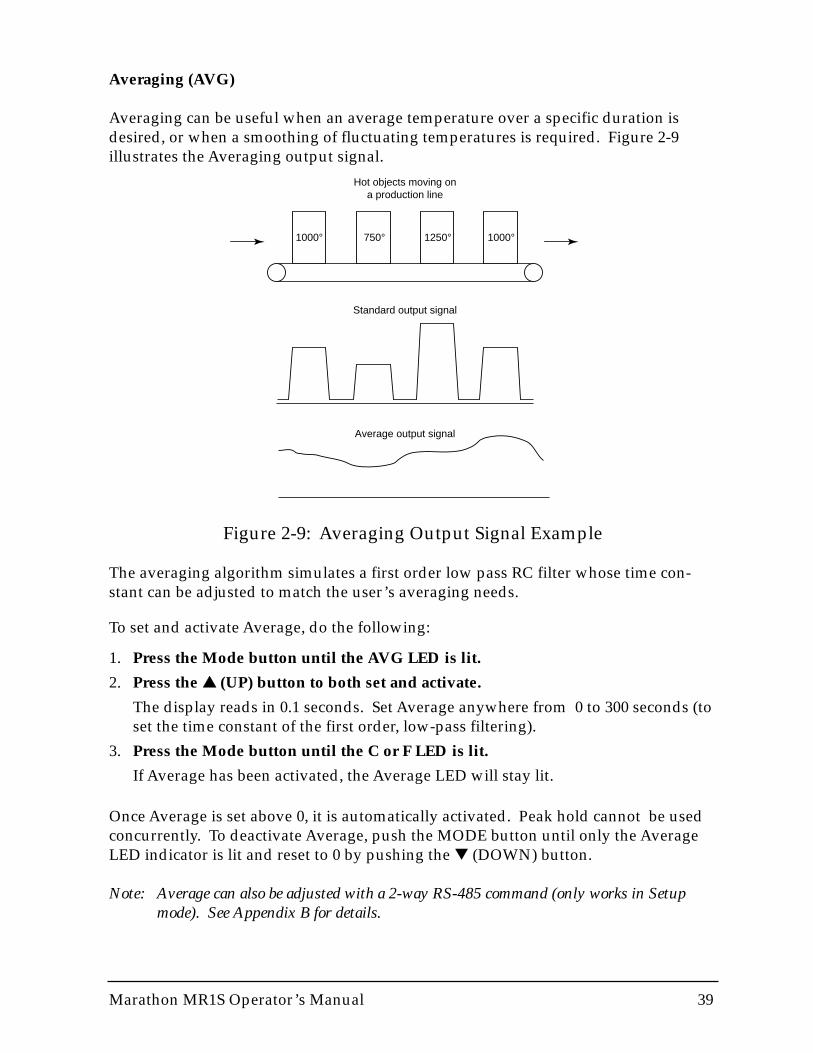
Averaging (AVG)
Averaging can be useful when an average temperature over a specific duration isdesired, or when a smoothing of fluctuating temperatures is required. Figure 2-9illustrates the Averaging output signal.
Figure 2-9: Averaging Output Signal Example
1000° 750° 1250° 1000°
Hot objects moving ona production line
Standard output signal
Average output signal
The averaging algorithm simulates a first order low pass RC filter whose time con-stant can be adjusted to match the user’s averaging needs.
To set and activate Average, do the following:
1. Press the Mode button until the AVG LED is lit.
2. Press the ▲▲ (UP) button to both set and activate.
The display reads in 0.1 seconds. Set Average anywhere from 0 to 300 seconds (toset the time constant of the first order, low-pass filtering).
3. Press the Mode button until the C or F LED is lit.
If Average has been activated, the Average LED will stay lit.
Once Average is set above 0, it is automatically activated. Peak hold cannot be usedconcurrently. To deactivate Average, push the MODE button until only the AverageLED indicator is lit and reset to 0 by pushing the ▼ (DOWN) button.
Note: Average can also be adjusted with a 2-way RS-485 command (only works in Setupmode). See Appendix B for details.
40 Marathon MR1S Operator’s Manual
2.4.2.3 Setpoint
The Setpoint is deactivated by default (alarm mode). Activating and adjusting theSetpoint is accomplished through software. Refer to Appendix B for information onthe sensor’s communication protocols.
Once the Setpoint is activated the relay changes state as the current temperature pass-es the setpoint temperature.
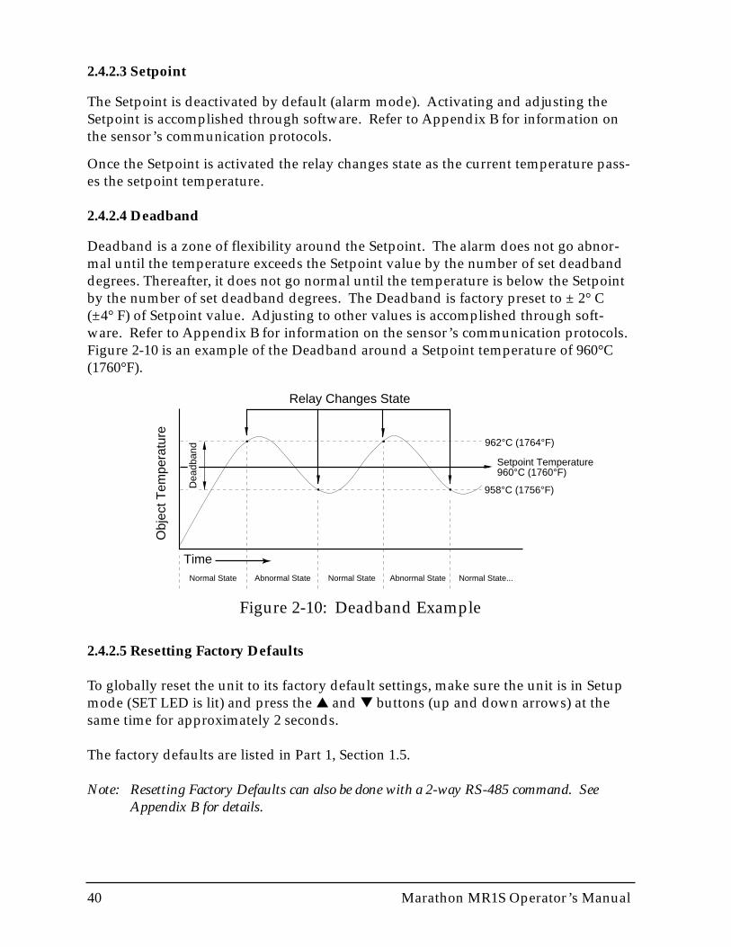
2.4.2.4 Deadband
Deadband is a zone of flexibility around the Setpoint. The alarm does not go abnor-mal until the temperature exceeds the Setpoint value by the number of set deadbanddegrees. Thereafter, it does not go normal until the temperature is below the Setpointby the number of set deadband degrees. The Deadband is factory preset to ± 2° C(±4° F) of Setpoint value. Adjusting to other values is accomplished through soft-ware. Refer to Appendix B for information on the sensor’s communication protocols.Figure 2-10 is an example of the Deadband around a Setpoint temperature of 960°C(1760°F).
Obj
ect T
empe
ratu
re
Time
Relay Changes State
962°C (1764°F)
Setpoint Temperature960°C (1760°F)
958°C (1756°F)
Normal State Normal State Normal State...Abnormal State Abnormal State
Dea
dban
d
Figure 2-10: Deadband Example
2.4.2.5 Resetting Factory Defaults
To globally reset the unit to its factory default settings, make sure the unit is in Setupmode (SET LED is lit) and press the ▲ and ▼ buttons (up and down arrows) at thesame time for approximately 2 seconds.
The factory defaults are listed in Part 1, Section 1.5.
Note: Resetting Factory Defaults can also be done with a 2-way RS-485 command. SeeAppendix B for details.

Marathon MR1S Operator’s Manual 41
Part 3 Multidrop Installation & Operation
This section explains the installation and operation of one or more Marathon infraredthermometers in a multidrop sensor-network environment.
Topics include...
• Preparation• Network Communication Setup• Mechanical Installation• Electrical Installation• Operation

42 Marathon MR1S Operator’s Manual

Marathon MR1S Operator’s Manual 43
3.0 MULTI-DROP SENSOR INSTALLATION
The multi-drop sensor installation consists of the following:
• Preparation• Communication Setup• Mechanical Installation• Electrical Installation
The most important part of the installation process is preparation. An additionalpreparation required for multidrop installations is the Network CommunicationSetup. Preparation and communications setup must be completed before proceedingto the mechanical installation.
3.1 MULTI-DROP PREPARATION
Sensor location, sensor configuration, and/or the number of sensors depend on theapplication. Before installing your sensors, you need to be aware of the ambient tem-perature of the location, the atmospheric quality of the location, and the possible elec-tromagnetic interference in that location. If you plan to use air purging and/or air orwater cooling, you need to have air and water connections available. Also, wiringand conduit runs must be considered, including computer and controller wiring andconnections, if used. The following subsections cover topics to consider before youinstall the sensor.
Note: All sensors, whether standard or with the air/water-cooled housing option, are suppliedwith an adjustable bracket and mounting nut. If necessary, the sensor can be mountedthrough a hole, or it can be mounted using a customer-supplied bracket or other acces-sories. (Refer to Part 1, Section 1.1 and 1.2 for an overview of the available accessoriesand options.)
3.1.1 Ambient Temperature
The sensing head is designed to operate in ambient temperatures between 0°C (32°F)and 50°C (120°F). The internal ambient temperature can vary from 10°C (50°F) to68°C (154°F). Internal temperatures outside this range will cause a failsafe error. Inambient conditions above 50°C (120°F), an optional air/water-cooled housing is avail-able to extend the operating range to 120°C (250°F) with air cooling, or 175°C (350°F)with water cooling. When using the water cooled housing, it is strongly recommend-ed to also use the air purge collar to avoid condensation on the lens. In ambient con-ditions up to 315°C (600°F), the ThermoJacket accessory should be used.
When using air or water cooling and air purging, make sure air and water suppliesare installed before proceeding with the sensor installation.
Water and air temperatures for cooling should be 15-30°C (60-86°F) for best perfor-mance. Chilled water or air below 10°C (50°F) is not recommended. For air purgingor air cooling, clean (filtered) or “instrument” air is recommended.

44 Marathon MR1S Operator’s Manual
3.1.2 Atmospheric Quality
Smoke, fumes, dust, and other contaminants in the air, as well as a dirty lens are gen-erally not a problem when using the 2-color mode (as long as the attenuation is equalin both spectral bands). However, if the lens gets too dirty, it cannot detect enoughinfrared energy to measure accurately, and the instrument will indicate a failure (seeSection 4.2). It is good practice to always keep the lens clean. The Air Purge Collarhelps keep contaminants from building up on the lens.
If you use air purging, make sure an air supply is installed before proceeding with thesensor installation.
3.1.3 Electrical Interference
To minimize electrical or electromagnetic interference or “noise,” be aware of the fol-lowing:
• Mount the sensor as far away as possible from potential sources of electricalinterference such as motorized equipment producing large step load changes.
• Use shielded wire for all input and output connections.
• Make sure the shield wire in the sensor cable is earth grounded.
• For additional protection, use conduit for the external connections. Solid con-duit is better than flexible conduit in high noise environments.
• Do not run AC power for other equipment in the same conduit.
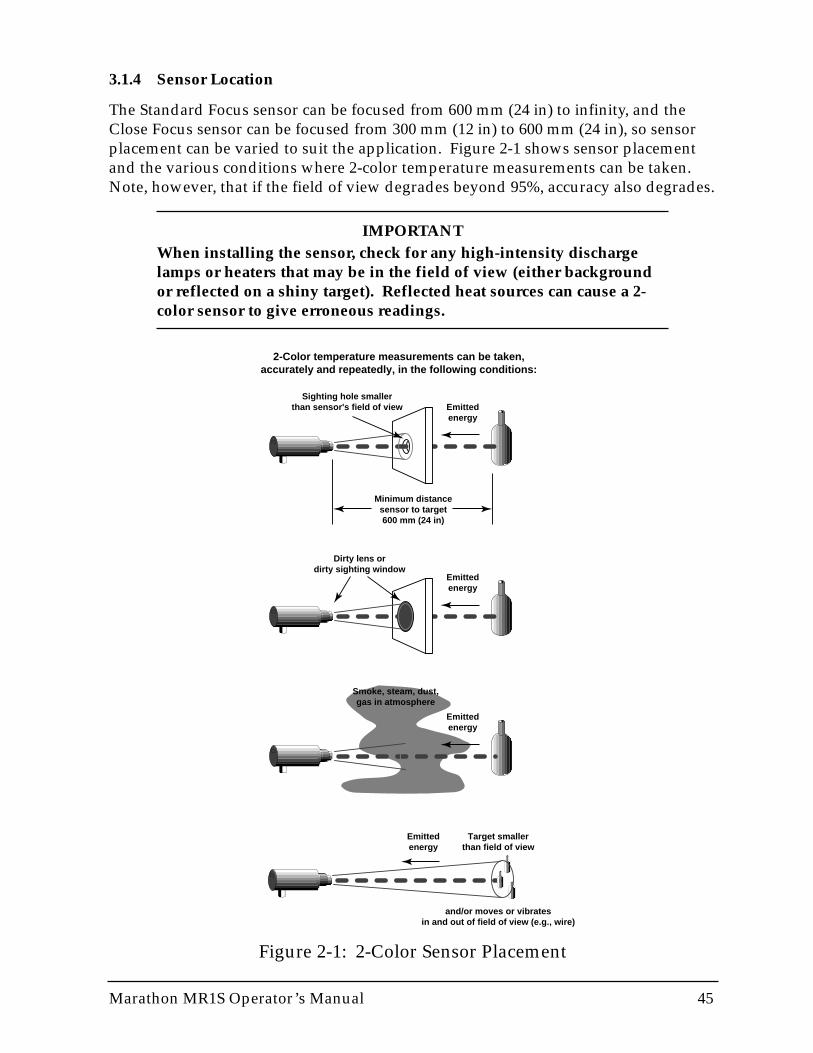
Marathon MR1S Operator’s Manual 45
3.1.4 Sensor Location
The Standard Focus sensor can be focused from 600 mm (24 in) to infinity, and theClose Focus sensor can be focused from 300 mm (12 in) to 600 mm (24 in), so sensorplacement can be varied to suit the application. Figure 2-1 shows sensor placementand the various conditions where 2-color temperature measurements can be taken.Note, however, that if the field of view degrades beyond 95%, accuracy also degrades.
IMPORTANTWhen installing the sensor, check for any high-intensity dischargelamps or heaters that may be in the field of view (either backgroundor reflected on a shiny target). Reflected heat sources can cause a 2-color sensor to give erroneous readings.
Figure 2-1: 2-Color Sensor Placement
Minimum distancesensor to target600 mm (24 in)
Emittedenergy
Sighting hole smallerthan sensor's field of view
Emittedenergy
Emittedenergy
Smoke, steam, dust,gas in atmosphere
Emittedenergy
Target smallerthan field of view
and/or moves or vibrates in and out of field of view (e.g., wire)
Dirty lens or dirty sighting window
2-Color temperature measurements can be taken, accurately and repeatedly, in the following conditions:
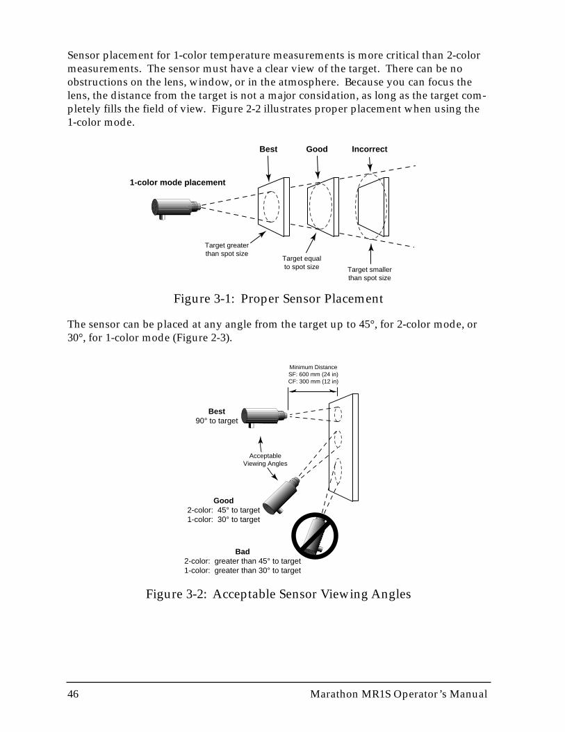
46 Marathon MR1S Operator’s Manual
Sensor placement for 1-color temperature measurements is more critical than 2-colormeasurements. The sensor must have a clear view of the target. There can be noobstructions on the lens, window, or in the atmosphere. Because you can focus thelens, the distance from the target is not a major considation, as long as the target com-pletely fills the field of view. Figure 2-2 illustrates proper placement when using the1-color mode.
Best Good Incorrect
Target equalto spot size Target smaller
than spot size
Target greaterthan spot size
1-color mode placement
Figure 3-1: Proper Sensor Placement
Best90° to target
Good2-color: 45° to target1-color: 30° to target
Bad2-color: greater than 45° to target1-color: greater than 30° to target
AcceptableViewing Angles
Minimum DistanceSF: 600 mm (24 in)CF: 300 mm (12 in)
Figure 3-2: Acceptable Sensor Viewing Angles
The sensor can be placed at any angle from the target up to 45°, for 2-color mode, or30°, for 1-color mode (Figure 2-3).
Marathon MR1S Operator’s Manual 47
3.1.5 Multi-drop Considerations
If you are installing two or more sensors in a multi-drop configuration, please beaware of the following:
• Each Marathon sensor must have a unique “address.” • Sensor setup and addressing must be done before mounting sensor in perma-
nent location.• Each sensor must be set to the same baud rate.• A 200 MHz or faster Pentium-class personal computer is suggested.• If your computer does not have RS-485 communication capabilities, you will
need to attach the RS-485 to RS-232 Converter accessory.
IMPORTANTWhen installing the sensor, check for any high-intensity dischargelamps or heaters that may be in the field of view (either backgroundor reflected on a shiny target). Reflected heat sources can cause erro-neous readings.

48 Marathon MR1S Operator’s Manual
3.2 NETWORK COMMUNICATION SETUP
The following sections cover software installation, preparing your sensors, and howto use the software to give each sensor a unique address. These steps should be com-pleted before installing the sensors in their permanent location.
3.2.1 Software Installation
The software that came with your Marathon sensor(s) consists of four separate pro-grams. These include the Network Communications Setup (covered in this section),the Graphic Setup and Display, the Sensor Network Setup and Display (displays tem-peratures and alarms for up to 32 sensors), and the Chat program (direct communica-tions between the user and the sensor). These programs are covered in Part 4.
Note: You can create your own programs customized to your application by using the com-munications protocols listed in Appendix B.
To install the software on a personal computer running Windows 95, Windows 98, orWindows NT 4.0 (Service Pack 3), complete the following steps:
1. Put Disk 1 in your floppy drive.
2. Click on the Start Button and select Run.
3. Type A:\Install and press the Return/Enter key.
4. Follow the installation instructions.
All necessary programs are installed in the Raytek program group.

Marathon MR1S Operator’s Manual 49
3.2.2 Preparing the Sensors for a 4-Wire Multidrop Installation
Before mounting the sensors in their permanent location, each one must be initializedwith a unique address so communication to and from the sensors and the computercan occur without problems. To set up your computer to initialize the sensors, com-plete the following steps (use Figure 3-3 as a guide):
1. Turn off your computer.
2. Wire a sensor cable to the right side of a terminal block (supplied with each cable),and attach the appropriate power supply and RS-485 cables to the other side.(Refer to Section 2.3, Electrical Installation, for terminal block information.)
3. Plug the RS-485 to RS-232 converter into your computer’s serial port, and plug inthe AC power supply cable if used. (Use the supplied 25-pin to 9-pin adapter ifnecessary.)
Note: This step is not necessary if your computer is equipped with an RS-485 interfacecard
4. Before turning on the computer, make sure the sensor and RS-485 to RS-232adapter power supplies are plugged in.
5. Turn on your computer.
RED
BLACK
PURPLE
GREY
BLACK
WHITE
GREEN
BROWN
BLUE
ORANGE
YELLOW
CLEAR
RELAY
NO/NC
COM
TRIGGER
+24 VDC
GROUND
TxA
TxB
RxA
RxB
+mA OUT
–mA OUT
SHIELD
PowerConnection
To Power Supply
Connectto Sensor
RS-485 4-wire Connection(For 2-Wire, connect
just TxA and TxB)
Customer Supplied Cable(Refer to Manufacture's
Wiring Diagram for TxA, TxB,RxA, and RxB Wire Colors)
RS-485 to RS-232 Converter(needed if computer does nothave an RS-485 adapter card)
From AC Adapter(optional)*
To Available COM Port
Terminal Block
* If there is no power supply connection between the terminal block and the converter, an AC adapter is required.
Figure 3-3: Wiring for 2-Wire Sensor Setup
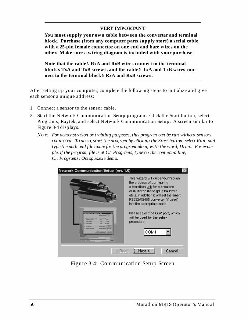
50 Marathon MR1S Operator’s Manual
VERY IMPORTANTYou must supply your own cable between the converter and terminalblock. Purchase (from any computer parts supply store) a serial cablewith a 25-pin female connector on one end and bare wires on theother. Make sure a wiring diagram is included with your purchase.
Note that the cable’s RxA and RxB wires connect to the terminalblock’s TxA and TxB screws, and the cable’s TxA and TxB wires con-nect to the terminal block’s RxA and RxB screws.
After setting up your computer, complete the following steps to initialize and giveeach sensor a unique address:
1. Connect a sensor to the sensor cable.
2. Start the Network Communication Setup program. Click the Start button, selectPrograms, Raytek, and select Network Communication Setup. A screen similar toFigure 3-4 displays.
Note: For demonstration or training purposes, this program can be run without sensorsconnected. To do so, start the program by clicking the Start button, select Run, andtype the path and file name for the program along with the word, Demo. For exam-ple, if the program file is at C:\Programs, type on the command line, C:\Programs\Octopus.exe demo.
Figure 3-4: Communication Setup Screen
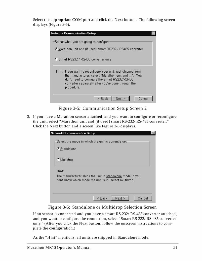
Marathon MR1S Operator’s Manual 51
Select the appropriate COM port and click the Next button. The following screendisplays (Figure 3-5).
3. If you have a Marathon sensor attached, and you want to configure or reconfigurethe unit, select “Marathon unit and (if used) smart RS-232/RS-485 converter.”Click the Next button and a screen like Figure 3-6 displays.
Figure 3-6: Standalone or Multidrop Selection Screen
Figure 3-5: Communication Setup Screen 2
If no sensor is connected and you have a smart RS-232/RS-485 converter attached,and you want to configure the connection, select “Smart RS-232/RS-485 converteronly.” (After you click the Next button, follow the onscreen instructions to com-plete the configuration.)
As the “Hint” mentions, all units are shipped in Standalone mode.
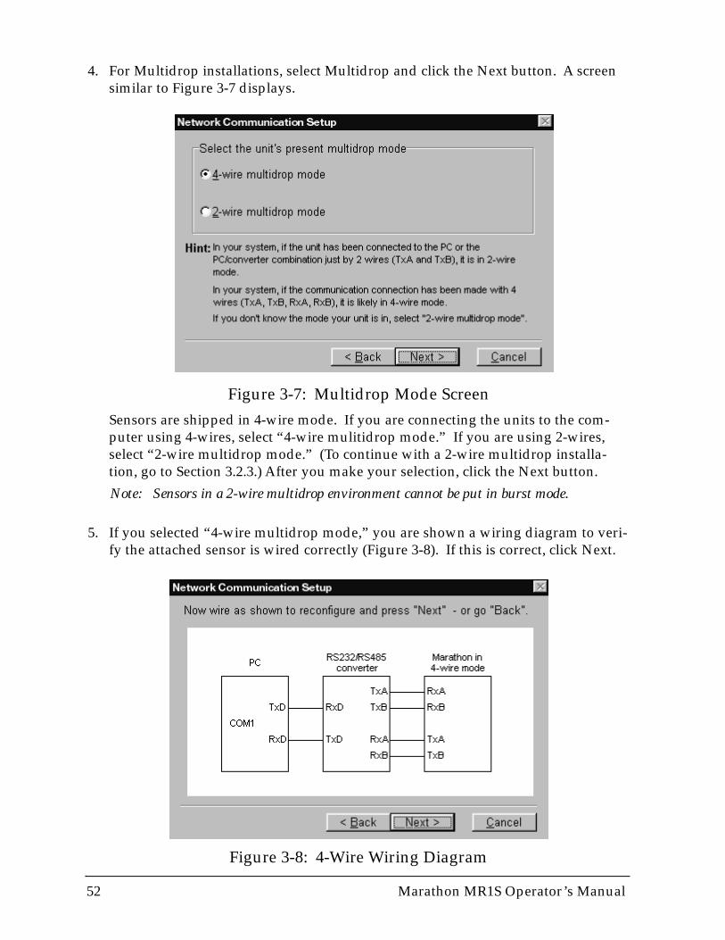
52 Marathon MR1S Operator’s Manual
4. For Multidrop installations, select Multidrop and click the Next button. A screensimilar to Figure 3-7 displays.
Figure 3-8: 4-Wire Wiring Diagram
Figure 3-7: Multidrop Mode ScreenSensors are shipped in 4-wire mode. If you are connecting the units to the com-puter using 4-wires, select “4-wire mulitidrop mode.” If you are using 2-wires,select “2-wire multidrop mode.” (To continue with a 2-wire multidrop installa-tion, go to Section 3.2.3.) After you make your selection, click the Next button.
Note: Sensors in a 2-wire multidrop environment cannot be put in burst mode.
5. If you selected “4-wire multidrop mode,” you are shown a wiring diagram to veri-fy the attached sensor is wired correctly (Figure 3-8). If this is correct, click Next.
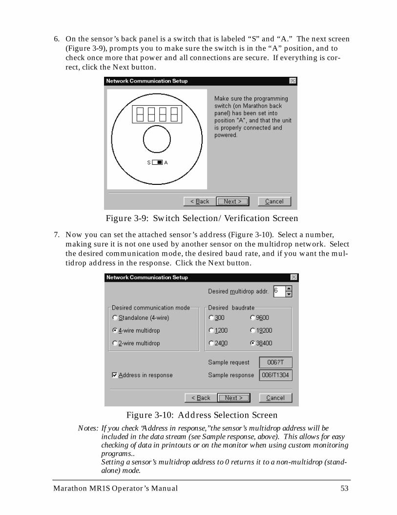
Marathon MR1S Operator’s Manual 53
Notes: If you check “Address in response,” the sensor’s multidrop address will beincluded in the data stream (see Sample response, above). This allows for easychecking of data in printouts or on the monitor when using custom monitoringprograms..Setting a sensor’s multidrop address to 0 returns it to a non-multidrop (stand-alone) mode.
6. On the sensor’s back panel is a switch that is labeled “S” and “A.” The next screen(Figure 3-9), prompts you to make sure the switch is in the “A” position, and tocheck once more that power and all connections are secure. If everything is cor-rect, click the Next button.
7. Now you can set the attached sensor’s address (Figure 3-10). Select a number,making sure it is not one used by another sensor on the multidrop network. Selectthe desired communication mode, the desired baud rate, and if you want the mul-tidrop address in the response. Click the Next button.
Figure 3-9: Switch Selection/Verification Screen
Figure 3-10: Address Selection Screen
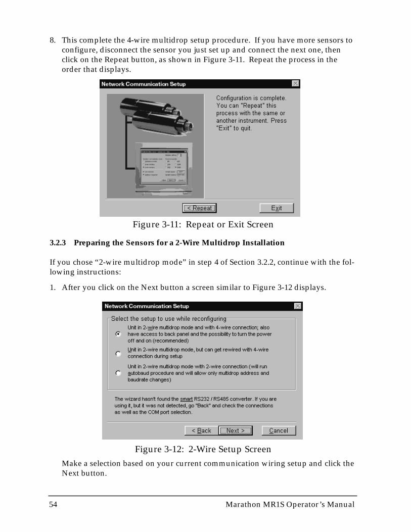
54 Marathon MR1S Operator’s Manual
Figure 3-11: Repeat or Exit Screen
Figure 3-12: 2-Wire Setup Screen
8. This complete the 4-wire multidrop setup procedure. If you have more sensors toconfigure, disconnect the sensor you just set up and connect the next one, thenclick on the Repeat button, as shown in Figure 3-11. Repeat the process in theorder that displays.
3.2.3 Preparing the Sensors for a 2-Wire Multidrop Installation
If you chose “2-wire multidrop mode” in step 4 of Section 3.2.2, continue with the fol-lowing instructions:
1. After you click on the Next button a screen similar to Figure 3-12 displays.
Make a selection based on your current communication wiring setup and click theNext button.
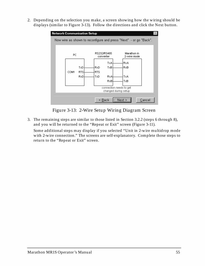
Marathon MR1S Operator’s Manual 55
2. Depending on the selection you make, a screen showing how the wiring should bedisplays (similar to Figure 3-13). Follow the directions and click the Next button.
3. The remaining steps are similar to those listed in Section 3.2.2 (steps 6 through 8),and you will be returned to the “Repeat or Exit” screen (Figure 3-11).
Some additional steps may display if you selected “Unit in 2-wire multidrop modewith 2-wire connection.” The screens are self-explanatory. Complete those steps toreturn to the “Repeat or Exit” screen.
Figure 3-13: 2-Wire Setup Wiring Diagram Screen
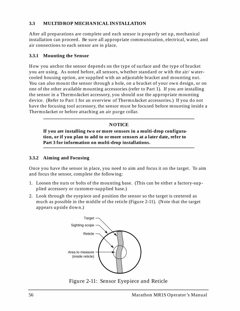
56 Marathon MR1S Operator’s Manual
3.3 MULTIDROP MECHANICAL INSTALLATION
After all preparations are complete and each sensor is properly set up, mechanicalinstallation can proceed. Be sure all appropriate communication, electrical, water, andair connections to each sensor are in place.
3.3.1 Mounting the Sensor
How you anchor the sensor depends on the type of surface and the type of bracketyou are using. As noted before, all sensors, whether standard or with the air/water-cooled housing option, are supplied with an adjustable bracket and mounting nut.You can also mount the sensor through a hole, on a bracket of your own design, or onone of the other available mounting accessories (refer to Part 1). If you are installingthe sensor in a ThermoJacket accessory, you should use the appropriate mountingdevice. (Refer to Part 1 for an overview of ThermoJacket accessories.) If you do nothave the focusing tool accessory, the sensor must be focused before mounting inside aThermoJacket or before attaching an air purge collar.
NOTICEIf you are installing two or more sensors in a multi-drop configura-tion, or if you plan to add to or more sensors at a later date, refer toPart 3 for information on multi-drop installations.
3.3.2 Aiming and Focusing
Once you have the sensor in place, you need to aim and focus it on the target. To aimand focus the sensor, complete the following:
1. Loosen the nuts or bolts of the mounting base. (This can be either a factory-sup-plied accessory or customer-supplied base.)
2. Look through the eyepiece and position the sensor so the target is centered asmuch as possible in the middle of the reticle (Figure 2-11). (Note that the targetappears upside down.)
Figure 2-11: Sensor Eyepiece and Reticle
Target
Sighting scope
Reticle
Area to measure(inside reticle)
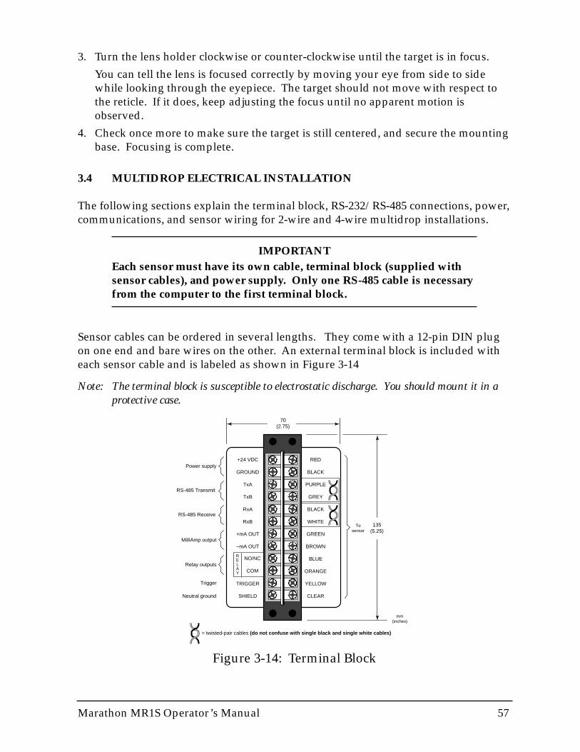
Marathon MR1S Operator’s Manual 57
3. Turn the lens holder clockwise or counter-clockwise until the target is in focus.
You can tell the lens is focused correctly by moving your eye from side to sidewhile looking through the eyepiece. The target should not move with respect tothe reticle. If it does, keep adjusting the focus until no apparent motion isobserved.
4. Check once more to make sure the target is still centered, and secure the mountingbase. Focusing is complete.
3.4 MULTIDROP ELECTRICAL INSTALLATION
The following sections explain the terminal block, RS-232/RS-485 connections, power,communications, and sensor wiring for 2-wire and 4-wire multidrop installations.
IMPORTANTEach sensor must have its own cable, terminal block (supplied withsensor cables), and power supply. Only one RS-485 cable is necessaryfrom the computer to the first terminal block.
Sensor cables can be ordered in several lengths. They come with a 12-pin DIN plugon one end and bare wires on the other. An external terminal block is included witheach sensor cable and is labeled as shown in Figure 3-14
Note: The terminal block is susceptible to electrostatic discharge. You should mount it in aprotective case.
Figure 3-14: Terminal Block
+24 VDC
GROUND
TxA
TxB
RxA
RxB
+mA OUT
–mA OUT
TRIGGER
SHIELD
RED
BLACK
PURPLE
GREY
BLACK
WHITE
GREEN
BROWN
BLUE
ORANGE
YELLOW
CLEAR
Power supply
RS-485 Transmit
RS-485 Receive
MilliAmp output
Relay outputs
Neutral ground
Trigger
= twisted-pair cables (do not confuse with single black and single white cables)
To sensor
RELAY
NO/NC
COM
135(5.25)
70(2.75)
mm(inches)
58 Marathon MR1S Operator’s Manual
To connect the bare wires to the terminal block, attach the sensor cable wires to thecolor coded side of the terminal block. Match the wire’s colors to the appropriatelylabeled terminals. If necessary, use Figure 2-12 as a guide. The connections on theopposite side of the terminal are discussed in the following subsections. If you cutthe cable to shorten it, notice that both sets of twisted-pair wires have drain wiresinside their insulation. These drain wires (and the white wire that is not part of thetwisted pair) must be connected to the terminal labeled CLEAR. (Only necessary ifyou cut the cable.)
WARNINGIncorrect wiring can damage the sensor and void the warranty. Beforeapplying power, make sure all connections are correct and secure.
Note: When using conduit for the cable, and when it has a compression fitting installed onthe conduit connection, the sensor head is rated NEMA-4 (IEC 529, IP 65).
IMPORTANTThe sensor cable may be shortened but not lengthened without theappropriate terminal block accessory. Longer cables are availablefrom the factory. Limit power cables to 60 meters (200 feet) or less.RS-485 cables can be extended up to 1200 meters (4000 feet).
Avoid installing the sensor cable in noisy electrical environmentssuch as around electrical motors, switch gear, or induction heaters. Inthese environments, it is recommended to install the cable in conduit.Note that the sensor head is designed to fit conduit directly.
3.4.1 Power
Connections from a 24 VDC (250 mA or higher) power supply attach to the first twoterminals on the terminal strip (as shown in Figure 2-3).
IMPORTANTIsolation is provided only when used with the appropriate Rayteksupplied power supply accessory.
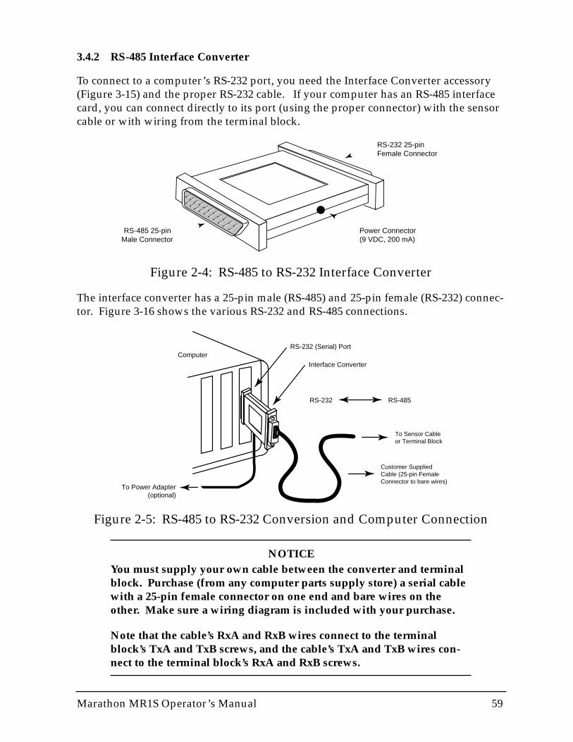
Marathon MR1S Operator’s Manual 59
3.4.2 RS-485 Interface Converter
To connect to a computer’s RS-232 port, you need the Interface Converter accessory(Figure 3-15) and the proper RS-232 cable. If your computer has an RS-485 interfacecard, you can connect directly to its port (using the proper connector) with the sensorcable or with wiring from the terminal block.
The interface converter has a 25-pin male (RS-485) and 25-pin female (RS-232) connec-tor. Figure 3-16 shows the various RS-232 and RS-485 connections.
NOTICEYou must supply your own cable between the converter and terminalblock. Purchase (from any computer parts supply store) a serial cablewith a 25-pin female connector on one end and bare wires on theother. Make sure a wiring diagram is included with your purchase.
Note that the cable’s RxA and RxB wires connect to the terminalblock’s TxA and TxB screws, and the cable’s TxA and TxB wires con-nect to the terminal block’s RxA and RxB screws.
Figure 2-5: RS-485 to RS-232 Conversion and Computer Connection
Interface ConverterComputer
To Power Adapter(optional)
RS-232 (Serial) Port
RS-232 RS-485
To Sensor Cable or Terminal Block
Customer SuppliedCable (25-pin FemaleConnector to bare wires)
Figure 2-4: RS-485 to RS-232 Interface Converter
Power Connector(9 VDC, 200 mA)
RS-232 25-pin Female Connector
RS-485 25-pin Male Connector
60 Marathon MR1S Operator’s Manual
Note: Personal computers can have up to 4 serial ports (RS-232 connections). These are list-ed as COM1, COM2, COM3, and COM4. Usually COM1 and COM2 are the onlyphysical connections on the back of the computer.
Connect the interface converter to an available COM port on your computer. If yourcomputer has a 9-pin serial connector, use a 25-pin to 9-pin adapter between the inter-face converter and the computer.
IMPORTANTOn older computers the COM1 port is used by a pointing device(mouse, trackball, etc.), and sometimes the COM2 port is connected toan external modem or fax/modem (an internal modem can also be setto use COM2). It is possible for two devices to share an interrupt(COM1/COM3 or COM2/COM4); however, they cannot be used at thesame time or your system might “crash.” You can connect the RS-232cable to the same port as, for instance, your modem, but you need tomake sure the modem is inactive while you use the sensor.
The RS-485 output is as follows:
Baud Rate: 300, 1200, 2400, 9600, 19200, 38400 (default)Note: Adjustable baud rate only available through 2-way RS-485.Data Format: 8 bits, no parity, 1 stop bitTwo-wire half-duplex or four-wire full duplex, point-to-point
For a full description of the RS-485 output string, see Appendix B.
WARNINGIf you are using the converter’s optional power adapter, note the fol-lowing: After connecting the serial cables, attach the adapter plug intothe converter BEFORE plugging the AC adapter into an AC outlet.
Marathon MR1S Operator’s Manual 61
3.4.3 Milliamp Output
The milliamp output is an analog output you can connect directly to a chart recorderor other recording device.
The analog output resolution for A and B models is 1°C or 1°F, C model is 1 °C or 2°F.
The analog output corresponds to either the 2-color or 1-color readings on the display.
Note: The mA output can be forced to a specific value, underrange, or overrange with a 2-way RS-485 command. See Appendix B for details. This feature is useful for testingor calibrating connected equipment.
3.4.4 Relay Outputs
The relay output is used as an alarm for failsafe conditions or as a setpoint relay.(Refer to Section 4.2 for failsafe information.) Relay outputs relate to the currentlydisplayed temperatue on the LED display.
Note: Since the way you use the relay outputs depends on the application, check with yoursales representative for the best way to use this feature.
The relay can be set to either NO (Normally Open) or NC (Normally Closed) with a 2-way RS-485 command depending on compatibility requirements of connected equip-ment. The relay can be forced on or off via 2-way RS-485 for testing connected equip-ment. See Appendix B for details.
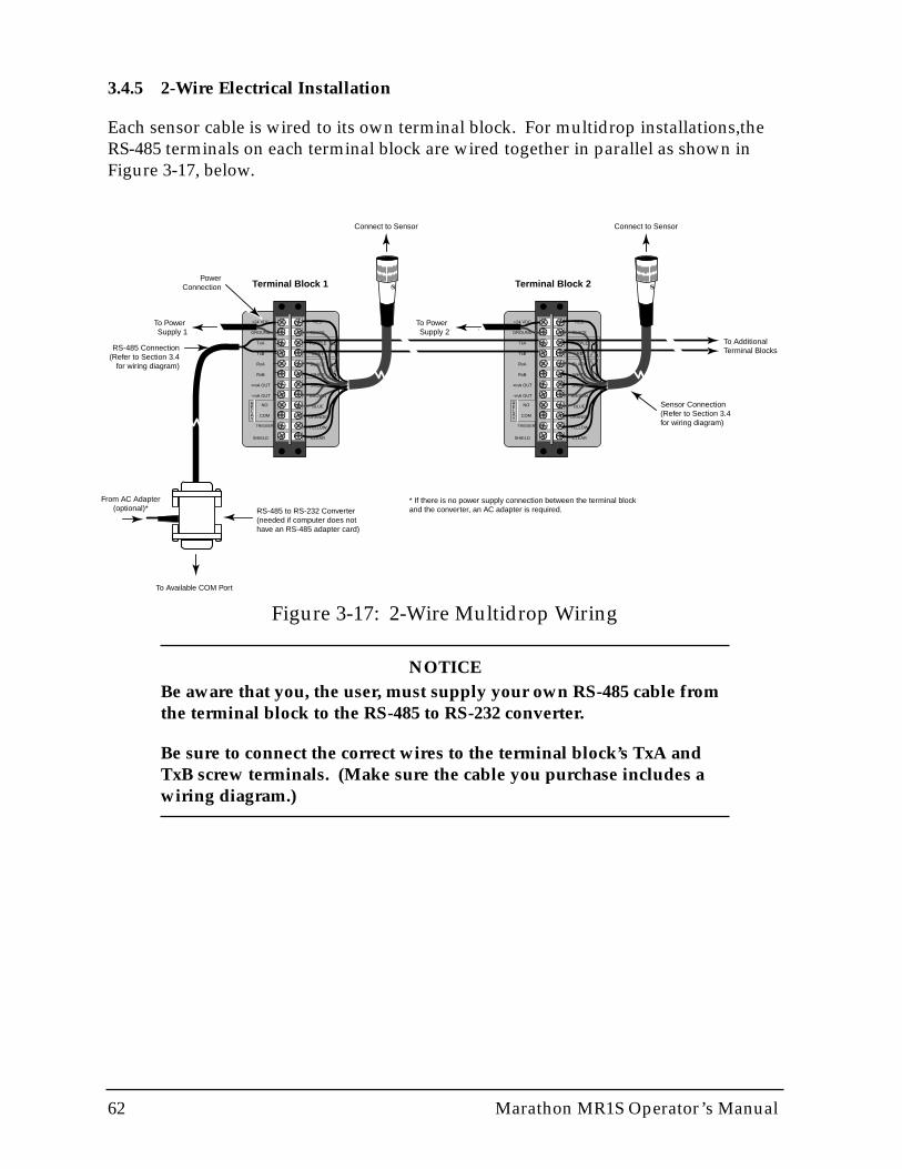
62 Marathon MR1S Operator’s Manual
RED
BLACK
PURPLE
GREY
BLACK
WHITE
GREEN
BROWN
BLUE
ORANGE
YELLOW
CLEAR
RELAY
NO
COM
TRIGGER
+24 VDC
GROUND
TxA
TxB
RxA
RxB
+mA OUT
–mA OUT
SHIELD
RED
BLACK
PURPLE
GREY
BLACK
WHITE
GREEN
BROWN
BLUE
ORANGE
YELLOW
CLEAR
RELAY
NO
COM
TRIGGER
+24 VDC
GROUND
TxA
TxB
RxA
RxB
+mA OUT
–mA OUT
SHIELD
PowerConnection
To Power Supply 1
To Power Supply 2
Connect to Sensor Connect to Sensor
RS-485 Connection(Refer to Section 3.4
for wiring diagram)
Sensor Connection(Refer to Section 3.4for wiring diagram)
RS-485 to RS-232 Converter(needed if computer does nothave an RS-485 adapter card)
From AC Adapter(optional)*
To Available COM Port
To AdditionalTerminal Blocks
Terminal Block 1 Terminal Block 2
* If there is no power supply connection between the terminal blockand the converter, an AC adapter is required.
Figure 3-17: 2-Wire Multidrop Wiring
3.4.5 2-Wire Electrical Installation
Each sensor cable is wired to its own terminal block. For multidrop installations,theRS-485 terminals on each terminal block are wired together in parallel as shown inFigure 3-17, below.
NOTICEBe aware that you, the user, must supply your own RS-485 cable fromthe terminal block to the RS-485 to RS-232 converter.
Be sure to connect the correct wires to the terminal block’s TxA andTxB screw terminals. (Make sure the cable you purchase includes awiring diagram.)
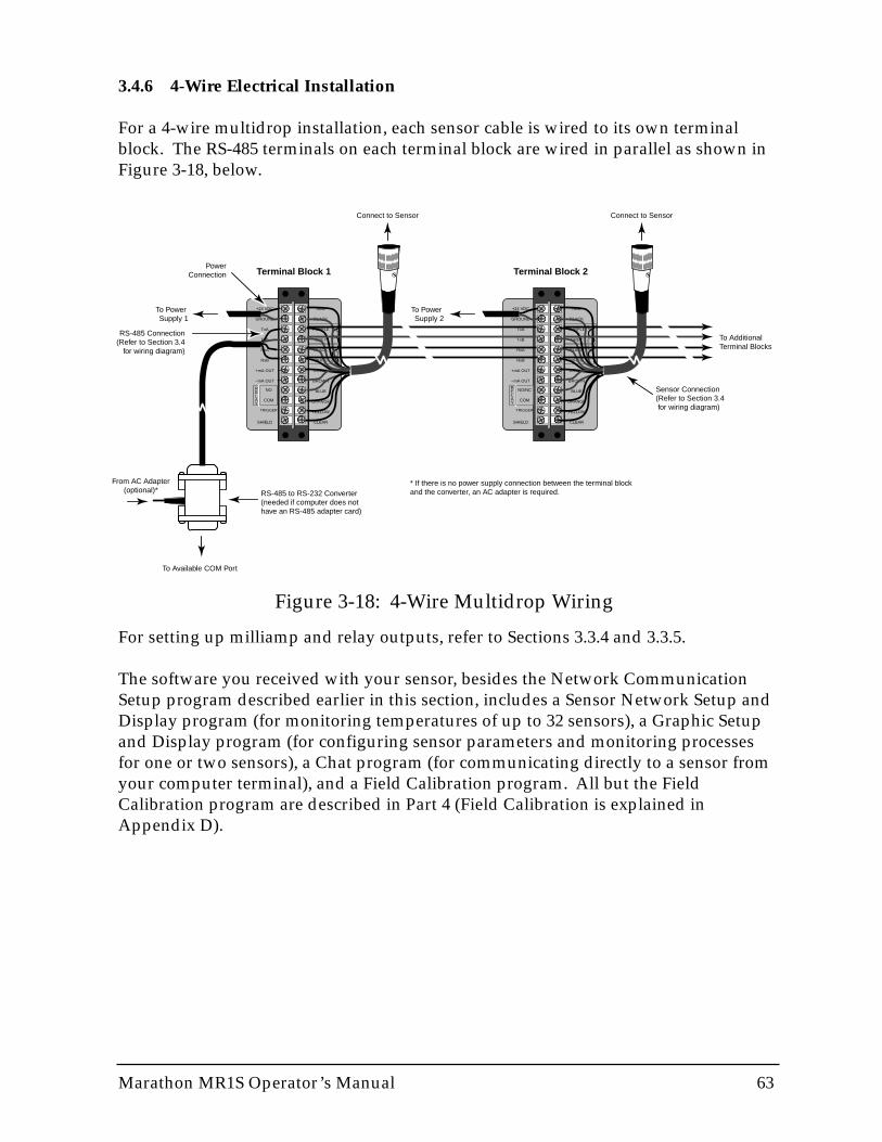
Marathon MR1S Operator’s Manual 63
3.4.6 4-Wire Electrical Installation
For a 4-wire multidrop installation, each sensor cable is wired to its own terminalblock. The RS-485 terminals on each terminal block are wired in parallel as shown inFigure 3-18, below.
For setting up milliamp and relay outputs, refer to Sections 3.3.4 and 3.3.5.
The software you received with your sensor, besides the Network CommunicationSetup program described earlier in this section, includes a Sensor Network Setup andDisplay program (for monitoring temperatures of up to 32 sensors), a Graphic Setupand Display program (for configuring sensor parameters and monitoring processesfor one or two sensors), a Chat program (for communicating directly to a sensor fromyour computer terminal), and a Field Calibration program. All but the FieldCalibration program are described in Part 4 (Field Calibration is explained inAppendix D).
RED
BLACK
PURPLE
GREY
BLACK
WHITE
GREEN
BROWN
BLUE
ORANGE
YELLOW
CLEAR
RELAY
NO
COM
TRIGGER
+24 VDC
GROUND
TxA
TxB
RxA
RxB
+mA OUT
–mA OUT
SHIELD
RED
BLACK
PURPLE
GREY
BLACK
WHITE
GREEN
BROWN
BLUE
ORANGE
YELLOW
CLEAR
RELAY
NO/NC
COM
TRIGGER
+24 VDC
GROUND
TxA
TxB
RxA
RxB
+mA OUT
–mA OUT
SHIELD
PowerConnection
To Power Supply 1
To Power Supply 2
Connect to Sensor Connect to Sensor
RS-485 Connection(Refer to Section 3.4
for wiring diagram)
Sensor Connection(Refer to Section 3.4 for wiring diagram)
RS-485 to RS-232 Converter(needed if computer does nothave an RS-485 adapter card)
From AC Adapter(optional)*
To Available COM Port
To AdditionalTerminal Blocks
Terminal Block 1 Terminal Block 2
* If there is no power supply connection between the terminal blockand the converter, an AC adapter is required.
Figure 3-18: 4-Wire Multidrop Wiring
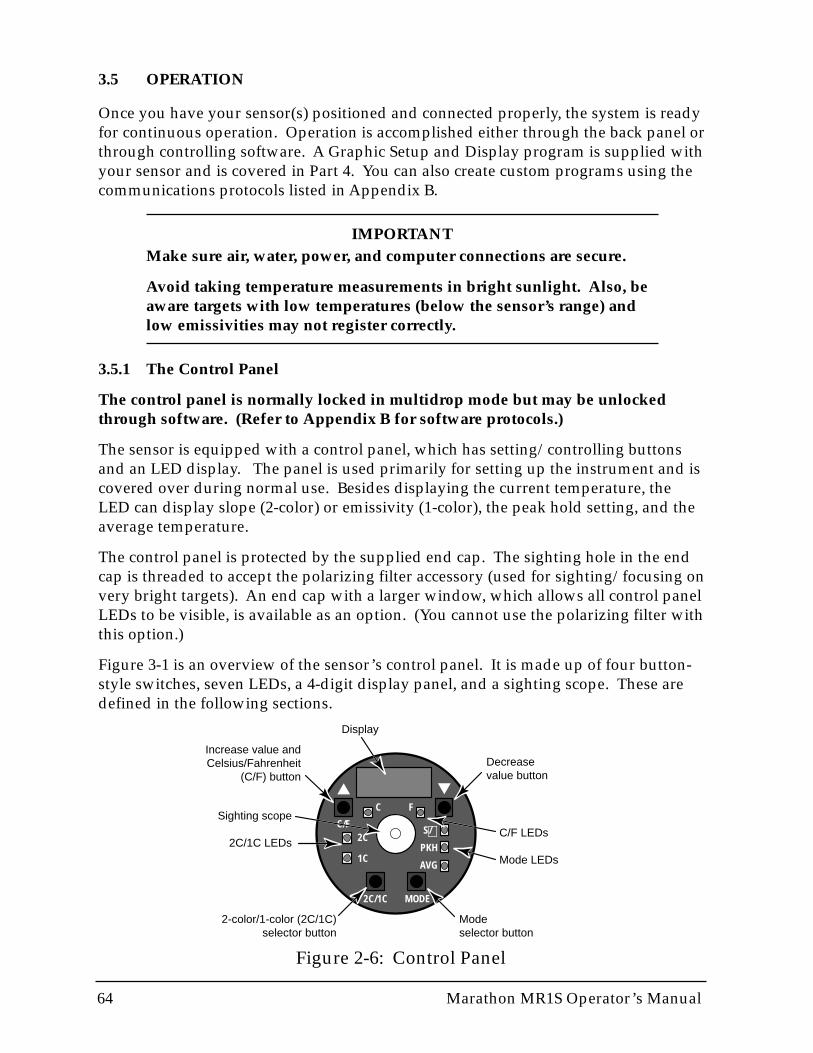
64 Marathon MR1S Operator’s Manual
3.5 OPERATION
Once you have your sensor(s) positioned and connected properly, the system is readyfor continuous operation. Operation is accomplished either through the back panel orthrough controlling software. A Graphic Setup and Display program is supplied withyour sensor and is covered in Part 4. You can also create custom programs using thecommunications protocols listed in Appendix B.
IMPORTANTMake sure air, water, power, and computer connections are secure.
Avoid taking temperature measurements in bright sunlight. Also, beaware targets with low temperatures (below the sensor’s range) andlow emissivities may not register correctly.
3.5.1 The Control Panel
The control panel is normally locked in multidrop mode but may be unlockedthrough software. (Refer to Appendix B for software protocols.)
The sensor is equipped with a control panel, which has setting/controlling buttonsand an LED display. The panel is used primarily for setting up the instrument and iscovered over during normal use. Besides displaying the current temperature, theLED can display slope (2-color) or emissivity (1-color), the peak hold setting, and theaverage temperature.
The control panel is protected by the supplied end cap. The sighting hole in the endcap is threaded to accept the polarizing filter accessory (used for sighting/focusing onvery bright targets). An end cap with a larger window, which allows all control panelLEDs to be visible, is available as an option. (You cannot use the polarizing filter withthis option.)
Figure 3-1 is an overview of the sensor’s control panel. It is made up of four button-style switches, seven LEDs, a 4-digit display panel, and a sighting scope. These aredefined in the following sections.
Figure 2-6: Control Panel
2C/1C MODE
C/F
C F
2C
1C
S/
PKH
AVG
▼▲
∋
Decreasevalue button
Mode selector button
Increase value and Celsius/Fahrenheit
(C/F) button
2-color/1-color (2C/1C) selector button
Sighting scope
2C/1C LEDsC/F LEDs
Mode LEDs
Display
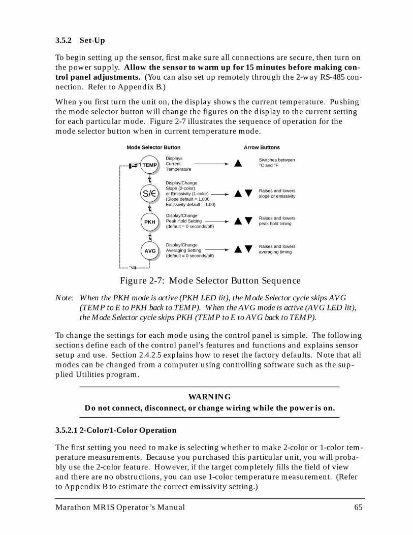
Marathon MR1S Operator’s Manual 65
3.5.2 Set-Up
To begin setting up the sensor, first make sure all connections are secure, then turn onthe power supply. Allow the sensor to warm up for 15 minutes before making con-trol panel adjustments. (You can also set up remotely through the 2-way RS-485 con-nection. Refer to Appendix B.)
When you first turn the unit on, the display shows the current temperature. Pushingthe mode selector button will change the figures on the display to the current settingfor each particular mode. Figure 2-7 illustrates the sequence of operation for themode selector button when in current temperature mode.
Note: When the PKH mode is active (PKH LED lit), the Mode Selector cycle skips AVG(TEMP to E to PKH back to TEMP). When the AVG mode is active (AVG LED lit),the Mode Selector cycle skips PKH (TEMP to E to AVG back to TEMP).
To change the settings for each mode using the control panel is simple. The followingsections define each of the control panel’s features and functions and explains sensorsetup and use. Section 2.4.2.5 explains how to reset the factory defaults. Note that allmodes can be changed from a computer using controlling software such as the sup-plied Utilities program.
WARNINGDo not connect, disconnect, or change wiring while the power is on.
3.5.2.1 2-Color/1-Color Operation
The first setting you need to make is selecting whether to make 2-color or 1-color tem-perature measurements. Because you purchased this particular unit, you will proba-bly use the 2-color feature. However, if the target completely fills the field of viewand there are no obstructions, you can use 1-color temperature measurement. (Referto Appendix B to estimate the correct emissivity setting.)
Figure 2-7: Mode Selector Button Sequence
TEMP
PKH
AVG
Displays Current Temperature
Switches between°C and °F
Raises and lowersslope or emissivity
Display/Change Slope (2-color)or Emissivity (1-color)(Slope default = 1.000Emissivity default = 1.00)
Display/Change Peak Hold Setting(default = 0 seconds/off)
Display/Change Averaging Setting(default = 0 seconds/off)
S/
Raises and lowerspeak hold timing
Raises and lowersaveraging timing
Mode Selector Button Arrow Buttons
66 Marathon MR1S Operator’s Manual
2C/1C Switch
To switch between 2-color and 1-color temperature measurement push the 2C/1Cselector button. A lit LED indicates the active measurement method. (Figure 3-1shows the location of the 2C/1C selector.)
Note: Switching affects the LED display and analog out but not the RS-485 out. Switchingbetween 1C and 2C can also be done with a 2-way RS-485 command. See Appendix Afor details.
Lockout Mode
The sensor has a remote locking feature that keeps the unit from being accidentallychanged from the control panel. (Lockout is the default when in multidrop mode.)This lockout mode denies access to all the switches on the control panel. It is avail-able through the RS-485 connection and can be unlocked only by a command from theremote computer. See Appendix B for details.
3.5.2.2 Modes
Pressing the mode selector button (Figure 3-1) cycles you through the four operatingmodes (as shown in Figure 3-2): temperature display mode, Slope/Emissivity displayand adjustment mode, Peak Hold output display and adjustment mode, Average out-put display and adjustment mode, and back to the temperature display mode.
Temperature
The temperature display can be set for either °C or °F by pressing the C/F selectorbutton (▲–up arrow), which also doubles as the Increase Value button for the othermodes. The Decrease Value (▼–down arrow) button is inactive in this mode. A litLED shows you whether the measured temperature is in °C or °F. Note that this set-ting influences the RS-485 output for both target and internal temperatures.
Slope/Emissivity
The slope is an adjustment that compensates for the differences in the emissivity ofthe two spectral ranges. The emissivity is a calculated ratio of infrared energy emittedby an object to the energy emitted by a blackbody at the same temperature (a perfectradiator has an emissivity of 1.00). The slope is preset at the factory at 1.000, and theemissivity is preset at 1.00. For information on determining an unknown emissivity,and for sample emissivities, refer to Appendix B.
You can set the unit up for either 2-color or 1-color measurements. The 2C/1C selec-tor button on the control panel switches between the two functions. One of the redLEDs above the button, labeled 2C and 1C, will show what function is active.
Marathon MR1S Operator’s Manual 67
For 2-color measurements—You need to set the slope for the material being mea-sured. To set the slope, do the following:
1. Press the Mode button until the LED is lit.
The current slope value shows on the display.
2. Press the ▲▲ or ▼▼ (UP or DOWN) button to change the value.
3. Press the Mode button several times until the temperature LED indicator is lit.
The displayed temperature will now be based on the new slope value.
IMPORTANTThe following slope settings are approximate and will vary depend-ing on the metal alloy and surface finish, as well as the application.These are supplied here as examples.
Set the slope to approximately 1.000 for measuring the following metals with oxidizedsurfaces:
• Cobalt • Stainless Steel • Nickel• Iron • Steel
Set the slope to approximately 1.060 for measuring the following metals with smooth,clean, unoxidized surfaces:
• Cobalt • Rhodium • Platinum• Iron • Stainless Steel • Tungsten• Molybdenum • Steel• Nickel • Tantalum
Molten iron also has an approximate slope setting of 1.060.
Unknown Slope—To measure the temperature of objects or materials that are not list-ed above, you will have to set the slope by doing the following (make sure the 2CLED is lit):
1. Take the temperature of the target’s surface.
Use a reliable contact or probe thermometer. If you have to measure several areason the target, use the average of the temperatures for the following steps.
2. Aim the unit at the target.
3. Press the Mode button until the LED is lit.
The current slope value shows on the display.
4. Press the ▲▲ or ▼▼ (UP or DOWN) button to change the value.
5. Press the Mode button several times until the C or F LED indicator is lit.
Compare the displayed temperature to that of the contact or probe thermometer’s.If they are not the same, repeat steps 3 through 5 until they are.
S/
∋
S/
∋
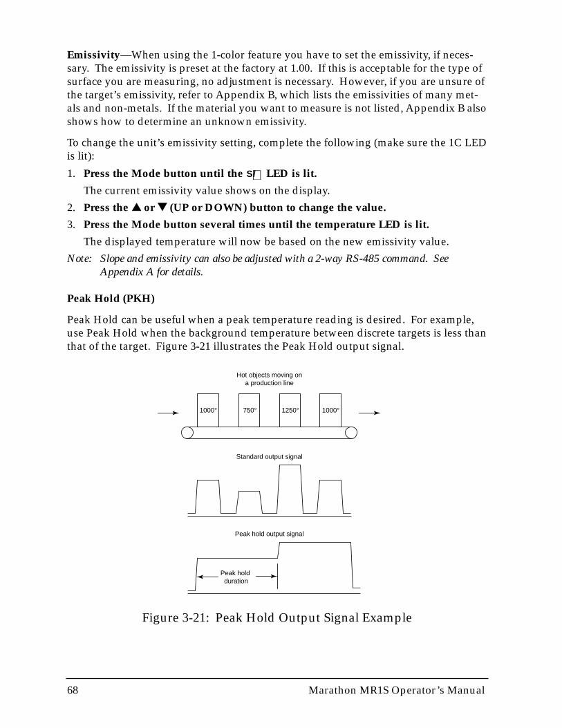
68 Marathon MR1S Operator’s Manual
Emissivity—When using the 1-color feature you have to set the emissivity, if neces-sary. The emissivity is preset at the factory at 1.00. If this is acceptable for the type ofsurface you are measuring, no adjustment is necessary. However, if you are unsure ofthe target’s emissivity, refer to Appendix B, which lists the emissivities of many met-als and non-metals. If the material you want to measure is not listed, Appendix B alsoshows how to determine an unknown emissivity.
To change the unit’s emissivity setting, complete the following (make sure the 1C LEDis lit):
1. Press the Mode button until the LED is lit.
The current emissivity value shows on the display.
2. Press the ▲▲ or ▼▼ (UP or DOWN) button to change the value.
3. Press the Mode button several times until the temperature LED is lit.
The displayed temperature will now be based on the new emissivity value.
Note: Slope and emissivity can also be adjusted with a 2-way RS-485 command. SeeAppendix A for details.
Peak Hold (PKH)
Peak Hold can be useful when a peak temperature reading is desired. For example,use Peak Hold when the background temperature between discrete targets is less thanthat of the target. Figure 3-21 illustrates the Peak Hold output signal.
S/
∋
1000° 750° 1250° 1000°
Hot objects moving ona production line
Standard output signal
Peak hold output signal
Peak hold duration
Figure 3-21: Peak Hold Output Signal Example

Marathon MR1S Operator’s Manual 69
When you activate Peak Hold, the instrument monitors the maximum temperatureseen over a predetermined time interval (duration). Should the unit measure a tem-perature higher than the one it is presently displaying, it immediately updates the dis-play and starts a new time interval. On the other hand, should it see no temperatureabove the one presently displayed, it will hold this value until the duration expires, atwhich time it will update to a new value equal to the highest temperature seen at thetime the interval expired. If the unit measures an intermediate temperature beforemeasuring ambient, and if the last object has passed, the unit will display and outputthe intermediate value for one more duration before ambient is finally displayed.Figure 3-21 illustrates this function. This algorithm prevents large changes in output,a desirable feature for controller applications.
To set and activate Peak Hold, do the following:
1. Press the Mode button until the PKH LED is lit.
2. Press the ▲▲ (UP) button to both set and activate.
The display reads in 0.1 seconds. Set Peak Hold from 0 to 299.9 seconds. If PeakHold is set to 300.0 seconds, a hardware reset is needed to trigger another reading.
3. Press the Mode button until the C or F LED is lit.
If Peak Hold has been activated, the Peak LED will stay lit.
Once Peak Hold is set above 0, it automatically activates. Note that Averaging (AVG)cannot be used concurrently. To deactivate Peak Hold, push the MODE button untilonly the PKH LED indicator is lit and reset to 0 by pushing the ▼ (DOWN) button.
Note: Peak Hold can also be adjusted with a 2-way RS-485 command. See Appendix B fordetails.
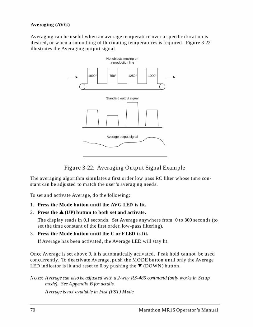
70 Marathon MR1S Operator’s Manual
Averaging (AVG)
Averaging can be useful when an average temperature over a specific duration isdesired, or when a smoothing of fluctuating temperatures is required. Figure 3-22illustrates the Averaging output signal.
Figure 3-22: Averaging Output Signal Example
1000° 750° 1250° 1000°
Hot objects moving ona production line
Standard output signal
Average output signal
The averaging algorithm simulates a first order low pass RC filter whose time con-stant can be adjusted to match the user’s averaging needs.
To set and activate Average, do the following:
1. Press the Mode button until the AVG LED is lit.
2. Press the ▲▲ (UP) button to both set and activate.
The display reads in 0.1 seconds. Set Average anywhere from 0 to 300 seconds (toset the time constant of the first order, low-pass filtering).
3. Press the Mode button until the C or F LED is lit.
If Average has been activated, the Average LED will stay lit.
Once Average is set above 0, it is automatically activated. Peak hold cannot be usedconcurrently. To deactivate Average, push the MODE button until only the AverageLED indicator is lit and reset to 0 by pushing the ▼ (DOWN) button.
Notes: Average can also be adjusted with a 2-way RS-485 command (only works in Setupmode). See Appendix B for details.
Average is not available in Fast (FST) Mode.
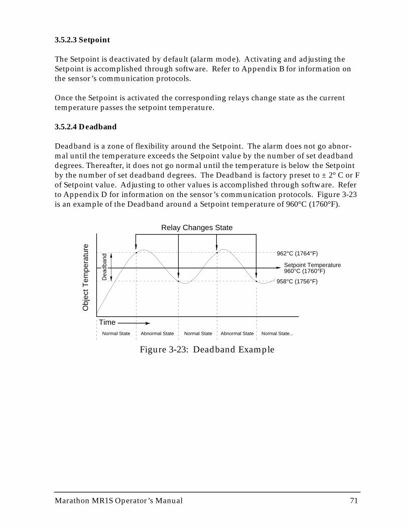
Marathon MR1S Operator’s Manual 71
3.5.2.3 Setpoint
The Setpoint is deactivated by default (alarm mode). Activating and adjusting theSetpoint is accomplished through software. Refer to Appendix B for information onthe sensor’s communication protocols.
Once the Setpoint is activated the corresponding relays change state as the currenttemperature passes the setpoint temperature.
3.5.2.4 Deadband
Deadband is a zone of flexibility around the Setpoint. The alarm does not go abnor-mal until the temperature exceeds the Setpoint value by the number of set deadbanddegrees. Thereafter, it does not go normal until the temperature is below the Setpointby the number of set deadband degrees. The Deadband is factory preset to ± 2° C or Fof Setpoint value. Adjusting to other values is accomplished through software. Referto Appendix D for information on the sensor’s communication protocols. Figure 3-23is an example of the Deadband around a Setpoint temperature of 960°C (1760°F).
Obj
ect T
empe
ratu
re
Time
Relay Changes State
962°C (1764°F)
Setpoint Temperature960°C (1760°F)
958°C (1756°F)
Normal State Normal State Normal State...Abnormal State Abnormal State
Dea
dban
d
Figure 3-23: Deadband Example

72 Marathon MR1S Operator’s Manual
3.5.2.5 Resetting Factory Defaults
To globally reset the unit to its factory default settings, make sure the unit is in Setupmode (SET LED is lit) and press the ▲ and ▼ buttons (up and down arrows) at thesame time for approximately 2 seconds.
The factory defaults are listed in Part 1, Section 1.5.
Note: Resetting Factory Defaults can also be done with a 2-way RS-485 command. SeeAppendix B for details.

Marathon MR1S Operator’s Manual 73
Part 4 Marathon Support Software Installation & User Guides
This section explains the installation and operation of the Marathon Support Softwareincluded with your sensors. The Graphic Setup and Display, Sensor Network Setupand Display, and Chat programs can be used in multidrop sensor environments. TheGraphic Setup and Display and Marathon Chat programs can be used in non-mul-tidrop environments.
Topics include...
• Installation• Graphic Setup and Display User Guide• Sensor Network Setup and Display User Guide• Marathon Chat Program User Guide
74 Marathon MR1S Operator’s Manual
SOFTWARE INSTALLATION
The software that came with your Marathon sensor(s) consists of five separate pro-grams. These include the Network Communications Setup (multidrop only–coveredin Part 3), the Graphic Setup and Display, the Sensor Network Setup and Display (dis-plays temperatures and alarms for up to 32 sensors), the Chat program (direct com-munications between the user and the sensor), and the Field Calibration program(covered in Appendix D).
Note: You can also create your own custom programs for your application by using the com-munications protocols listed in Appendix B.
IMPORTANTIf you installed your sensors in a multidrop environment using Part 3as a guide, you have already installed all necessary software. Skip thefollowing steps.
To install the software on a personal computer running Windows 95, Windows 98, orWindows NT 4.0 (Service Pack 3), complete the following steps:
1. Put Disk 1 in your floppy drive.
2. Click on the Start Button and select Run.
3. Type A:\Install and press the Return/Enter key.
4. Follow the installation instructions.
All necessary programs are installed in the Raytek program group.
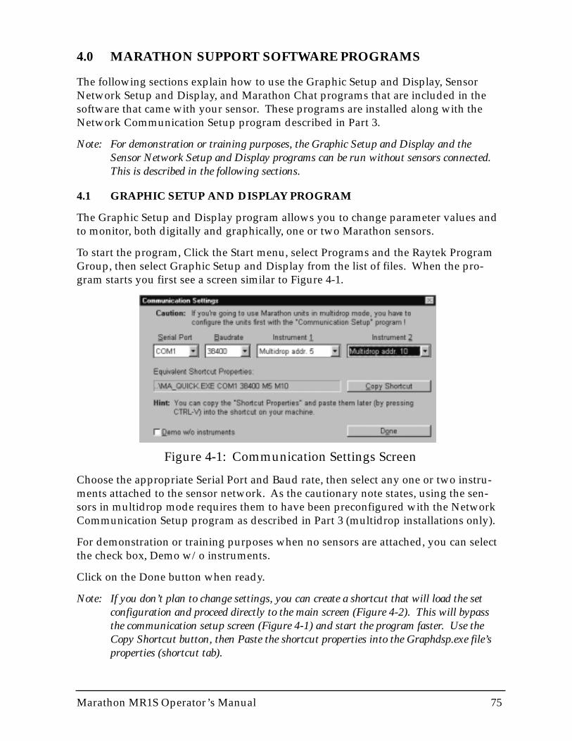
Marathon MR1S Operator’s Manual 75
4.0 MARATHON SUPPORT SOFTWARE PROGRAMS
The following sections explain how to use the Graphic Setup and Display, SensorNetwork Setup and Display, and Marathon Chat programs that are included in thesoftware that came with your sensor. These programs are installed along with theNetwork Communication Setup program described in Part 3.
Note: For demonstration or training purposes, the Graphic Setup and Display and theSensor Network Setup and Display programs can be run without sensors connected.This is described in the following sections.
4.1 GRAPHIC SETUP AND DISPLAY PROGRAM
The Graphic Setup and Display program allows you to change parameter values andto monitor, both digitally and graphically, one or two Marathon sensors.
To start the program, Click the Start menu, select Programs and the Raytek ProgramGroup, then select Graphic Setup and Display from the list of files. When the pro-gram starts you first see a screen similar to Figure 4-1.
Figure 4-1: Communication Settings Screen
Choose the appropriate Serial Port and Baud rate, then select any one or two instru-ments attached to the sensor network. As the cautionary note states, using the sen-sors in multidrop mode requires them to have been preconfigured with the NetworkCommunication Setup program as described in Part 3 (multidrop installations only).
For demonstration or training purposes when no sensors are attached, you can selectthe check box, Demo w/o instruments.
Click on the Done button when ready.
Note: If you don’t plan to change settings, you can create a shortcut that will load the setconfiguration and proceed directly to the main screen (Figure 4-2). This will bypassthe communication setup screen (Figure 4-1) and start the program faster. Use theCopy Shortcut button, then Paste the shortcut properties into the Graphdsp.exe file’sproperties (shortcut tab).
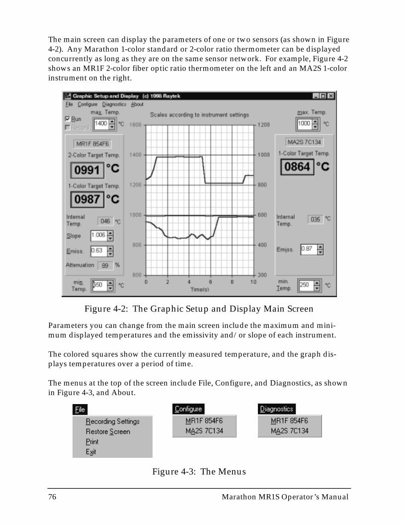
76 Marathon MR1S Operator’s Manual
The main screen can display the parameters of one or two sensors (as shown in Figure4-2). Any Marathon 1-color standard or 2-color ratio thermometer can be displayedconcurrently as long as they are on the same sensor network. For example, Figure 4-2shows an MR1F 2-color fiber optic ratio thermometer on the left and an MA2S 1-colorinstrument on the right.
Figure 4-2: The Graphic Setup and Display Main Screen
Parameters you can change from the main screen include the maximum and mini-mum displayed temperatures and the emissivity and/or slope of each instrument.
The colored squares show the currently measured temperature, and the graph dis-plays temperatures over a period of time.
The menus at the top of the screen include File, Configure, and Diagnostics, as shownin Figure 4-3, and About.
Figure 4-3: The Menus
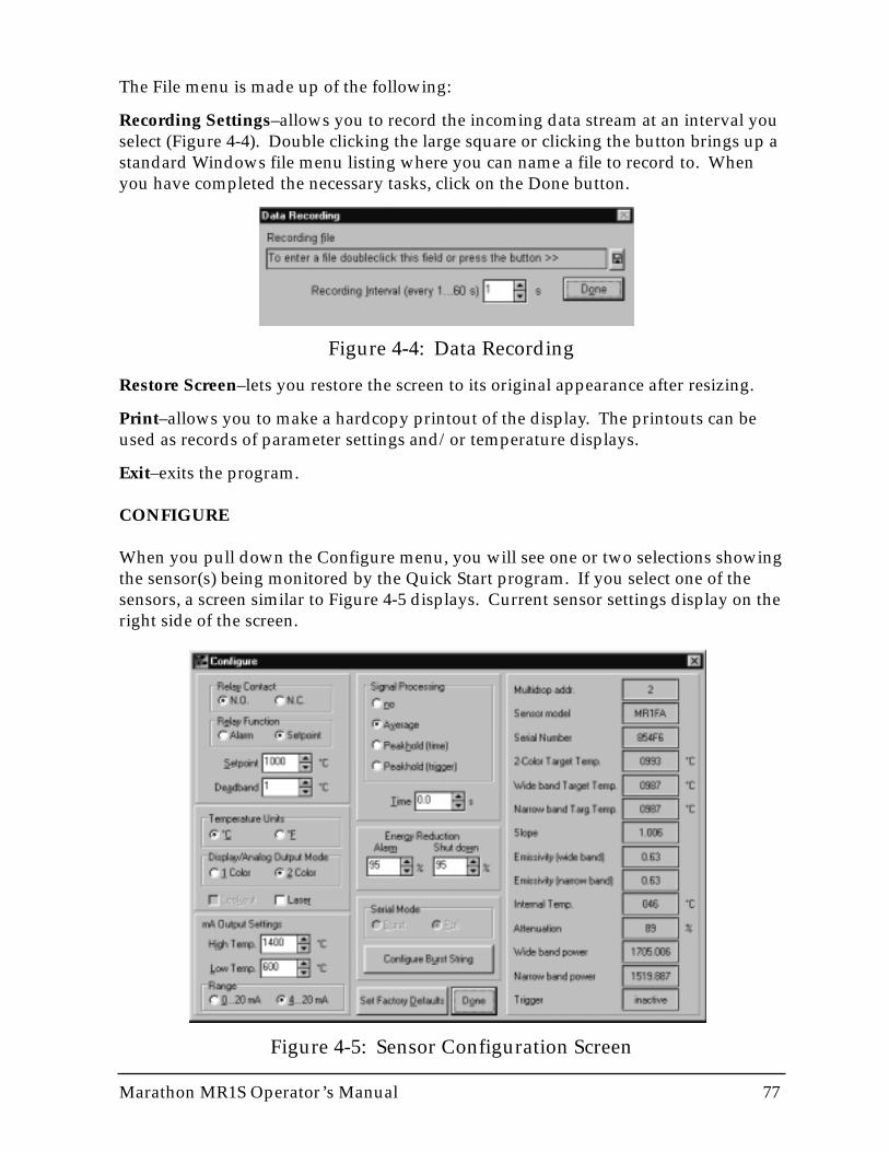
Figure 4-5: Sensor Configuration Screen
Marathon MR1S Operator’s Manual 77
The File menu is made up of the following:
Recording Settings–allows you to record the incoming data stream at an interval youselect (Figure 4-4). Double clicking the large square or clicking the button brings up astandard Windows file menu listing where you can name a file to record to. Whenyou have completed the necessary tasks, click on the Done button.
Figure 4-4: Data Recording
Restore Screen–lets you restore the screen to its original appearance after resizing.
Print–allows you to make a hardcopy printout of the display. The printouts can beused as records of parameter settings and/or temperature displays.
Exit–exits the program.
CONFIGURE
When you pull down the Configure menu, you will see one or two selections showingthe sensor(s) being monitored by the Quick Start program. If you select one of thesensors, a screen similar to Figure 4-5 displays. Current sensor settings display on theright side of the screen.
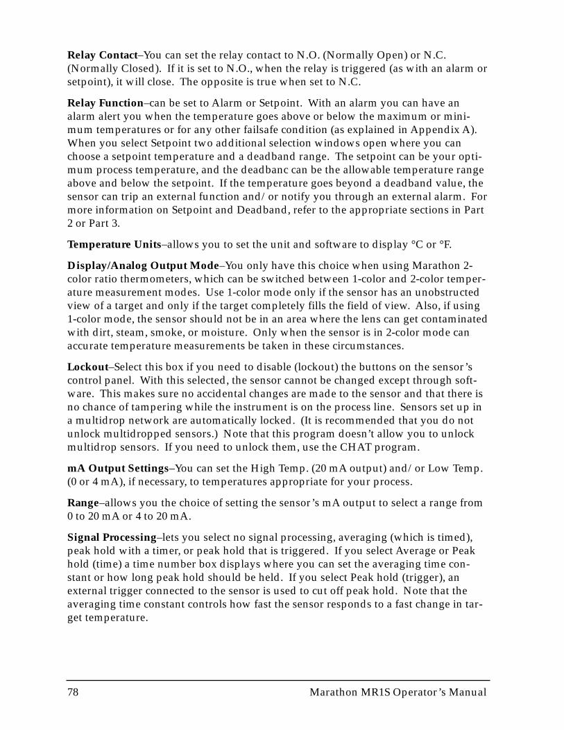
78 Marathon MR1S Operator’s Manual
Relay Contact–You can set the relay contact to N.O. (Normally Open) or N.C.(Normally Closed). If it is set to N.O., when the relay is triggered (as with an alarm orsetpoint), it will close. The opposite is true when set to N.C.
Relay Function–can be set to Alarm or Setpoint. With an alarm you can have analarm alert you when the temperature goes above or below the maximum or mini-mum temperatures or for any other failsafe condition (as explained in Appendix A).When you select Setpoint two additional selection windows open where you canchoose a setpoint temperature and a deadband range. The setpoint can be your opti-mum process temperature, and the deadbanc can be the allowable temperature rangeabove and below the setpoint. If the temperature goes beyond a deadband value, thesensor can trip an external function and/or notify you through an external alarm. Formore information on Setpoint and Deadband, refer to the appropriate sections in Part2 or Part 3.
Temperature Units–allows you to set the unit and software to display °C or °F.
Display/Analog Output Mode–You only have this choice when using Marathon 2-color ratio thermometers, which can be switched between 1-color and 2-color temper-ature measurement modes. Use 1-color mode only if the sensor has an unobstructedview of a target and only if the target completely fills the field of view. Also, if using1-color mode, the sensor should not be in an area where the lens can get contaminatedwith dirt, steam, smoke, or moisture. Only when the sensor is in 2-color mode canaccurate temperature measurements be taken in these circumstances.
Lockout–Select this box if you need to disable (lockout) the buttons on the sensor’scontrol panel. With this selected, the sensor cannot be changed except through soft-ware. This makes sure no accidental changes are made to the sensor and that there isno chance of tampering while the instrument is on the process line. Sensors set up ina multidrop network are automatically locked. (It is recommended that you do notunlock multidropped sensors.) Note that this program doesn’t allow you to unlockmultidrop sensors. If you need to unlock them, use the CHAT program.
mA Output Settings–You can set the High Temp. (20 mA output) and/or Low Temp.(0 or 4 mA), if necessary, to temperatures appropriate for your process.
Range–allows you the choice of setting the sensor’s mA output to select a range from0 to 20 mA or 4 to 20 mA.
Signal Processing–lets you select no signal processing, averaging (which is timed),peak hold with a timer, or peak hold that is triggered. If you select Average or Peakhold (time) a time number box displays where you can set the averaging time con-stant or how long peak hold should be held. If you select Peak hold (trigger), anexternal trigger connected to the sensor is used to cut off peak hold. Note that theaveraging time constant controls how fast the sensor responds to a fast change in tar-get temperature.
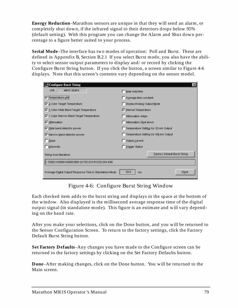
Marathon MR1S Operator’s Manual 79
Energy Reduction–Marathon sensors are unique in that they will send an alarm, orcompletely shut down, if the infrared signal to their detectors drops below 95%(default setting). With this program you can change the Alarm and Shut down per-centage to a figure better suited to your process.
Serial Mode–The interface has two modes of operation: Poll and Burst. These aredefined in Appendix B, Section B.2.1 If you select Burst mode, you also have the abili-ty to select sensor output parameters to display and/or record by clicking theConfigure Burst String button. If you click the button, a screen similar to Figure 4-6displays. Note that this screen’s contents vary depending on the sensor model.
Figure 4-6: Configure Burst String Window
Each checked item adds to the burst string and displays in the space at the bottom ofthe window. Also displayed is the millisecond average response time of the digitaloutput signal (in standalone mode). This figure is an estimate and will vary depend-ing on the baud rate.
After you make your selections, click on the Done button, and you will be returned tothe Sensor Configuration Screen. To return to the factory settings, click the FactoryDefault Burst String button.
Set Factory Defaults–Any changes you have made to the Configure screen can bereturned to the factory settings by clicking on the Set Factory Defaults button.
Done–After making changes, click on the Done button. You will be returned to theMain screen.
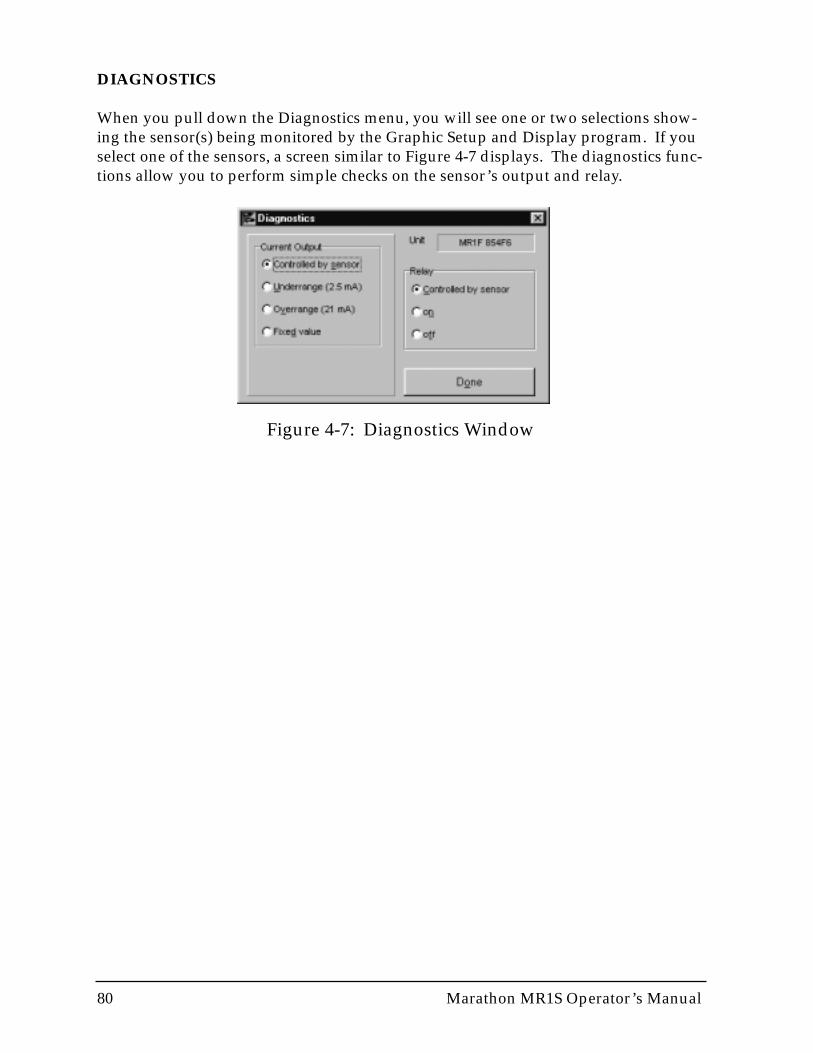
80 Marathon MR1S Operator’s Manual
DIAGNOSTICS
When you pull down the Diagnostics menu, you will see one or two selections show-ing the sensor(s) being monitored by the Graphic Setup and Display program. If youselect one of the sensors, a screen similar to Figure 4-7 displays. The diagnostics func-tions allow you to perform simple checks on the sensor’s output and relay.
Figure 4-7: Diagnostics Window
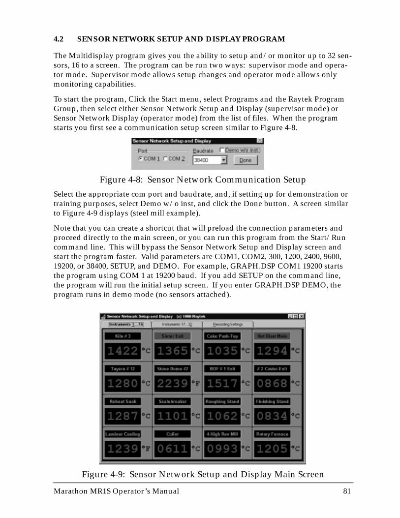
Figure 4-9: Sensor Network Setup and Display Main Screen
Marathon MR1S Operator’s Manual 81
4.2 SENSOR NETWORK SETUP AND DISPLAY PROGRAM
The Multidisplay program gives you the ability to setup and/or monitor up to 32 sen-sors, 16 to a screen. The program can be run two ways: supervisor mode and opera-tor mode. Supervisor mode allows setup changes and operator mode allows onlymonitoring capabilities.
To start the program, Click the Start menu, select Programs and the Raytek ProgramGroup, then select either Sensor Network Setup and Display (supervisor mode) orSensor Network Display (operator mode) from the list of files. When the programstarts you first see a communication setup screen similar to Figure 4-8.
Figure 4-8: Sensor Network Communication Setup
Select the appropriate com port and baudrate, and, if setting up for demonstration ortraining purposes, select Demo w/o inst, and click the Done button. A screen similarto Figure 4-9 displays (steel mill example).
Note that you can create a shortcut that will preload the connection parameters andproceed directly to the main screen, or you can run this program from the Start/Runcommand line. This will bypass the Sensor Network Setup and Display screen andstart the program faster. Valid parameters are COM1, COM2, 300, 1200, 2400, 9600,19200, or 38400, SETUP, and DEMO. For example, GRAPH.DSP COM1 19200 startsthe program using COM 1 at 19200 baud. If you add SETUP on the command line,the program will run the initial setup screen. If you enter GRAPH.DSP DEMO, theprogram runs in demo mode (no sensors attached).
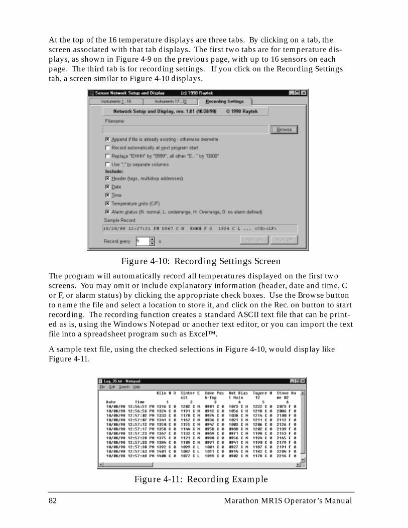
82 Marathon MR1S Operator’s Manual
At the top of the 16 temperature displays are three tabs. By clicking on a tab, thescreen associated with that tab displays. The first two tabs are for temperature dis-plays, as shown in Figure 4-9 on the previous page, with up to 16 sensors on eachpage. The third tab is for recording settings. If you click on the Recording Settingstab, a screen similar to Figure 4-10 displays.
Figure 4-10: Recording Settings Screen
The program will automatically record all temperatures displayed on the first twoscreens. You may omit or include explanatory information (header, date and time, Cor F, or alarm status) by clicking the appropriate check boxes. Use the Browse buttonto name the file and select a location to store it, and click on the Rec. on button to startrecording. The recording function creates a standard ASCII text file that can be print-ed as is, using the Windows Notepad or another text editor, or you can import the textfile into a spreadsheet program such as Excel™.
A sample text file, using the checked selections in Figure 4-10, would display likeFigure 4-11.
Figure 4-11: Recording Example
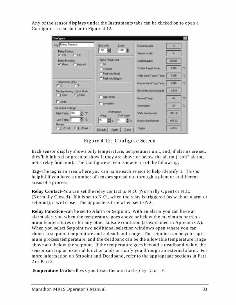
Marathon MR1S Operator’s Manual 83
Any of the sensor displays under the Instruments tabs can be clicked on to open aConfigure screen similar to Figure 4-12.
Figure 4-12: Configure Screen
Each sensor display shows only temperature, temperature unit, and, if alarms are set,they’ll blink red or green to show if they are above or below the alarm (“soft” alarm,not a relay function). The Configure screen is made up of the following:
Tag–The tag is an area where you can name each sensor to help identify it. This ishelpful if you have a number of sensors spread out through a plant or at differentareas of a process.
Relay Contact–You can set the relay contact to N.O. (Normally Open) or N.C.(Normally Closed). If it is set to N.O., when the relay is triggered (as with an alarm orsetpoint), it will close. The opposite is true when set to N.C.
Relay Function–can be set to Alarm or Setpoint. With an alarm you can have analarm alert you when the temperature goes above or below the maximum or mini-mum temperatures or for any other failsafe condition (as explained in Appendix A).When you select Setpoint two additional selection windows open where you canchoose a setpoint temperature and a deadband range. The setpoint can be your opti-mum process temperature, and the deadbanc can be the allowable temperature rangeabove and below the setpoint. If the temperature goes beyond a deadband value, thesensor can trip an external function and/or notify you through an external alarm. Formore information on Setpoint and Deadband, refer to the appropriate sections in Part2 or Part 3.
Temperature Units–allows you to set the unit to display °C or °F.
Display/Analog Output Mode–You only have this choice when using Marathon 2-color ratio thermometers, which can be switched between 1-color and 2-color temper-ature measurement modes. Use 1-color mode only if the sensor has an unobstructedview of a target and only if the target completely fills the field of view. Also, if using1-color mode, the sensor should not be in an area where the lens can get contaminatedwith dirt, steam, smoke, or moisture. Only when the sensor is in 2-color mode canaccurate temperature measurements be taken in these circumstances.
mA Output Settings–You can set the High Temp. (20 mA output) and/or Low Temp.(0 or 4 mA), if necessary, to temperatures appropriate for your process.
Range–allows you the choice of setting the sensor’s mA output to cover a range from0 to 20 mA or 4 to 20 mA.
Emissivity/Slope–You can change the emissivity and/or slope of an instrument byclicking on the up and down arrows or by entering a new number in the box.Changing these values are necessary only if the target being measured requires it.Refer to Appendix E for sample emissivities for metals and non-metals. Note thatSlope is only available for 2-color ratio instruments.
Signal Processing–lets you select no signal processing, averaging (which is timed),peak hold with a timer, or peak hold that is triggered. If you select Average or Peakhold (time) a time number box displays where you can set the averaging time con-stant or how long peak hold should be held. If you select Peak hold (trigger), anexternal trigger connected to the sensor is used to cut off peak hold. Note that theaveraging time constant controls how fast the sensor responds to a fast change in tar-get temperature.
High Alarm/Low Alarm–Selecting one or both of these check boxes allows visualmonitoring of each unit if it goes above or below an alarm level. When you select acheck box, a numeric control pops up allowing you to set the alarm level. This isindependent of relay. The name (tag) on a temperature display will blink either red orgreen depending on the condition. If there is an alarm condition on the second pageof sensors, an alert (independent of relay alarm) pops up in the middle of the firstpage screen allowing you to immediately go the second page.
Attenuation–Marathon sensors are unique in that they will send an alarm, or com-pletely shut down, if the infrared signal to their detectors drops below 95% (defaultsetting). With this program you can change the Alarm and Shut down percentage to afigure better suited to your process.
After you make any configuration changes, click on the Apply or Done button. Toswitch the sensor back to its factory settings, click on the Default button.
DISPLAY INFORMATIONYou can change the text and background colors for each temperaturewindow, and the colors for the titles over each window (normal andflashing alarms) by clicking the right mouse button over the tempera-ture display or text window.
84 Marathon MR1S Operator’s Manual
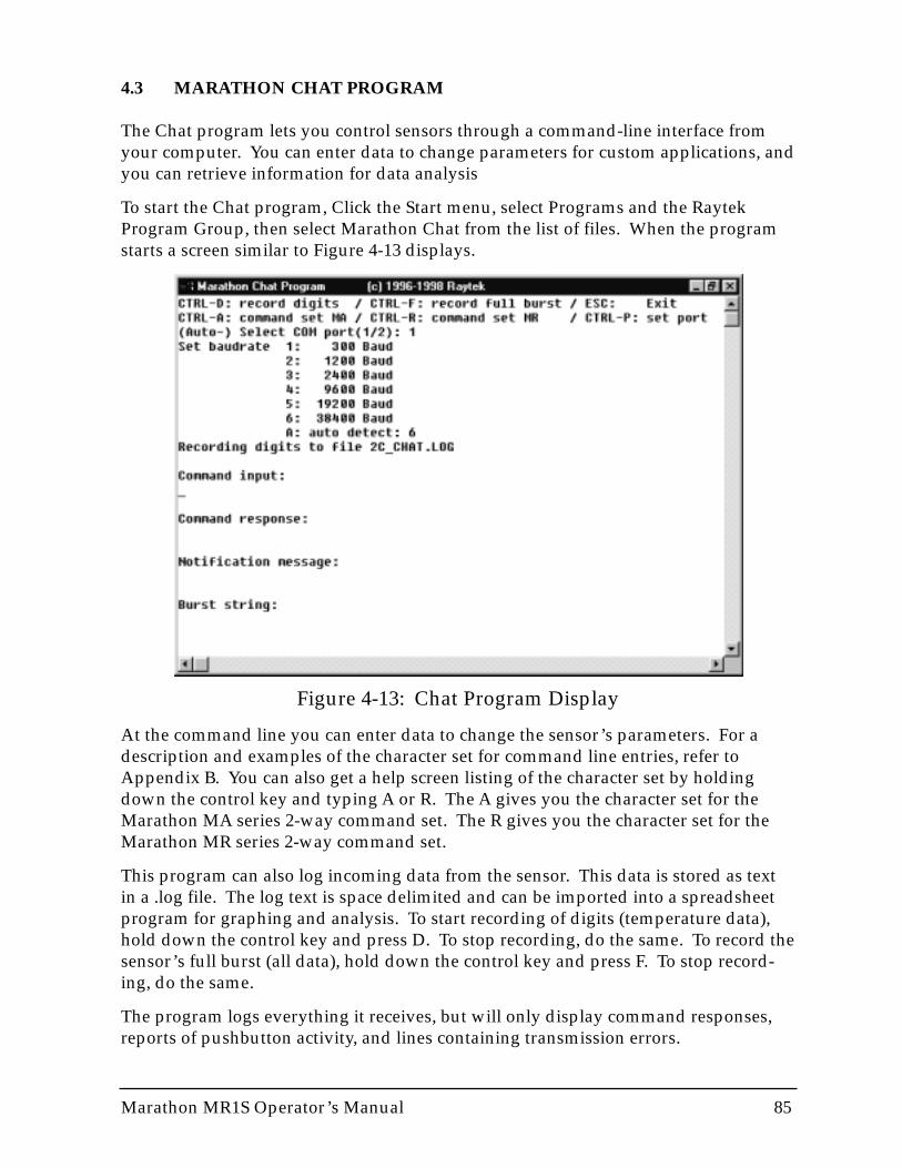
Marathon MR1S Operator’s Manual 85
4.3 MARATHON CHAT PROGRAM
The Chat program lets you control sensors through a command-line interface fromyour computer. You can enter data to change parameters for custom applications, andyou can retrieve information for data analysis
To start the Chat program, Click the Start menu, select Programs and the RaytekProgram Group, then select Marathon Chat from the list of files. When the programstarts a screen similar to Figure 4-13 displays.
Figure 4-13: Chat Program Display
At the command line you can enter data to change the sensor’s parameters. For adescription and examples of the character set for command line entries, refer toAppendix B. You can also get a help screen listing of the character set by holdingdown the control key and typing A or R. The A gives you the character set for theMarathon MA series 2-way command set. The R gives you the character set for theMarathon MR series 2-way command set.
This program can also log incoming data from the sensor. This data is stored as textin a .log file. The log text is space delimited and can be imported into a spreadsheetprogram for graphing and analysis. To start recording of digits (temperature data),hold down the control key and press D. To stop recording, do the same. To record thesensor’s full burst (all data), hold down the control key and press F. To stop record-ing, do the same.
The program logs everything it receives, but will only display command responses,reports of pushbutton activity, and lines containing transmission errors.

86 Marathon MR1S Operator’s Manual

Marathon MR1S Operator’s Manual 87
Appendices
The appendices consist of additional information to help you maintain and operateyour Marathon infrared thermometer.
Topics include...
• Troubleshooting and Maintenance• Programming Guide• Object Emissivity• DIN Connector Wiring• Traceability of Instrument Calibration• CE Conformity for European Community

88 Marathon MR1S Operator’s Manual

Marathon MR1S Operator’s Manual 89
APPENDIX A: TROUBLESHOOTING AND MAINTENANCE
Our sales representatives and customer service are always at your disposal for ques-tions regarding application assistance, calibration, repair, and solutions to specificproblems. Please contact your local sales representative if you need assistance. Inmany cases, problems can be solved over the telephone. If you need to return equip-ment for servicing, calibration, or repair, please contact our Service Department beforeshipping. Phone numbers are listed on the Warranty/Copyright page at the begin-ning of this manual.
A.1 TROUBLESHOOTING MINOR PROBLEMS
Table A-1 lists common symptoms, their causes, and possible solutions. If you areexperiencing a problem that is not listed below, please call our Service Department.
Table A-1: Troubleshooting
SYMPTOM PROBABLE CAUSE SOLUTION
No output
Erroneous temperature
Erroneous temperature
Erroneous temperature
Erroneous temperature
Temperature fluctuates
No power to instrument
Faulty sensor cable
Field of view obstruction
Window dirty
Wrong slope or emissivity
Wrong signal processing
Check the power supply
Verify cable continuity
Remove the obstruction
Clean the window (see Section 4.3)
Correct the setting
Correct Peak Hold or Average settings
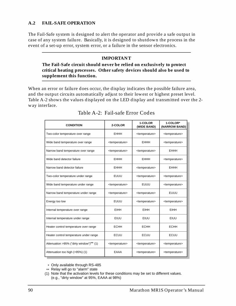
90 Marathon MR1S Operator’s Manual
A.2 FAIL-SAFE OPERATION
The Fail-Safe system is designed to alert the operator and provide a safe output incase of any system failure. Basically, it is designed to shutdown the process in theevent of a set-up error, system error, or a failure in the sensor electronics.
IMPORTANTThe Fail-Safe circuit should never be relied on exclusively to protectcritical heating processes. Other safety devices should also be used tosupplement this function.
When an error or failure does occur, the display indicates the possible failure area,and the output circuits automatically adjust to their lowest or highest preset level.Table A-2 shows the values displayed on the LED display and transmitted over the 2-way interface.
Table A-2: Fail-safe Error Codes
CONDITION 2-COLOR1-COLOR 1-COLOR*
(WIDE BAND) (NARROW BAND)
EHHH
<temperature>
<temperature>
EHHH
EHHH
EUUU
<temperature>
<temperature>
EUUU
EIHH
EIUU
ECHH
ECUU
<temperature>
EAAA
<temperature>
EHHH
<temperature>
EHHH
<temperature>
<temperature>
EUUU
<temperature>
<temperature>
EIHH
EIUU
ECHH
ECUU
<temperature>
<temperature>
<temperature>
<temperature>
EHHH
<temperature>
EHHH
<temperature>
<temperature>
EUUU
<temperature>
EIHH
EIUU
ECHH
ECUU
<temperature>
<temperature>
Two-color temperature over range
Wide band temperature over range
Narrow band temperature over range
Wide band detector failure
Narrow band detector failure
Two-color temperature under range
Wide band temperature under range
Narrow band temperature under range
Energy too low
Internal temperature over range
Internal temperature under range
Heater control temperature over range
Heater control temperature under range
Attenuation >95% ("dirty window")** (1)
Attenuation too high (>95%) (1)
***
(1)
Only available through RS-485Relay will go to "alarm" stateNote that the activation levels for these conditions may be set to different values.(e.g., "dirty window" at 95%, EAAA at 98%)
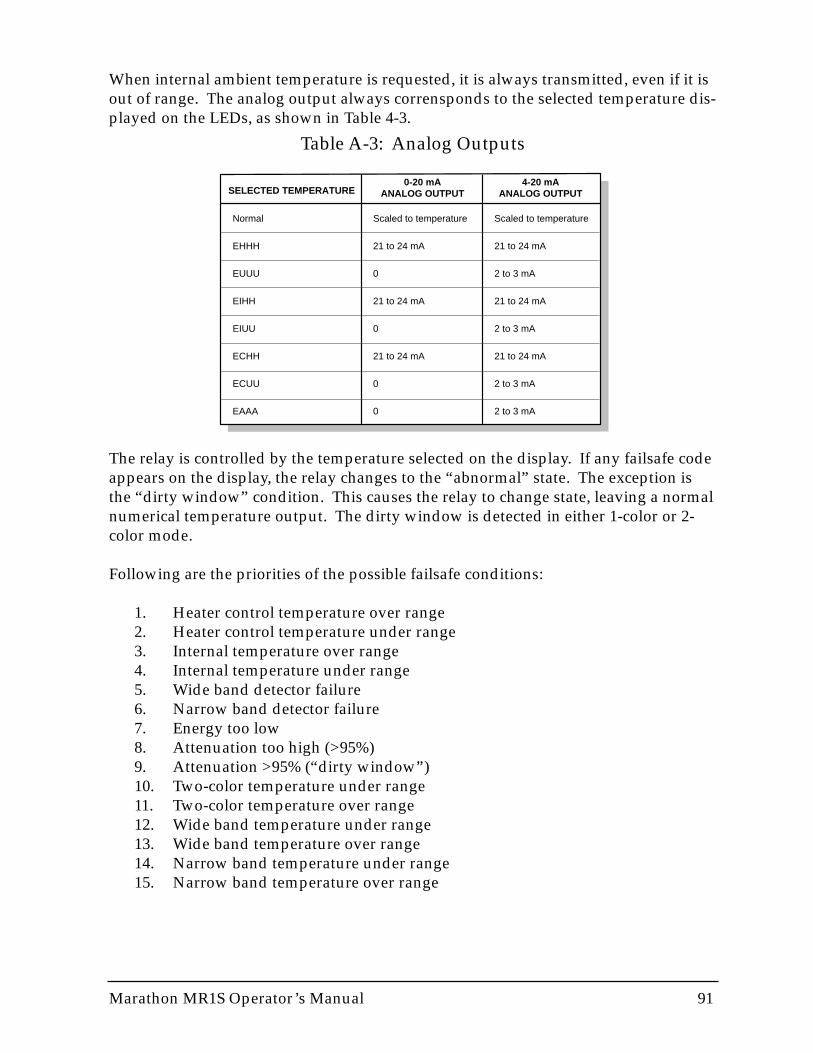
Marathon MR1S Operator’s Manual 91
When internal ambient temperature is requested, it is always transmitted, even if it isout of range. The analog output always corrensponds to the selected temperature dis-played on the LEDs, as shown in Table 4-3.
Table A-3: Analog Outputs
The relay is controlled by the temperature selected on the display. If any failsafe codeappears on the display, the relay changes to the “abnormal” state. The exception isthe “dirty window” condition. This causes the relay to change state, leaving a normalnumerical temperature output. The dirty window is detected in either 1-color or 2-color mode.
Following are the priorities of the possible failsafe conditions:
1. Heater control temperature over range2. Heater control temperature under range3. Internal temperature over range4. Internal temperature under range5. Wide band detector failure6. Narrow band detector failure7. Energy too low8. Attenuation too high (>95%)9. Attenuation >95% (“dirty window”)10. Two-color temperature under range11. Two-color temperature over range12. Wide band temperature under range13. Wide band temperature over range14. Narrow band temperature under range15. Narrow band temperature over range
SELECTED TEMPERATURE4-20 mA
ANALOG OUTPUT0-20 mA
ANALOG OUTPUT
Scaled to temperature
21 to 24 mA
2 to 3 mA
21 to 24 mA
2 to 3 mA
21 to 24 mA
2 to 3 mA
2 to 3 mA
Scaled to temperature
21 to 24 mA
0
21 to 24 mA
0
21 to 24 mA
0
0
Normal
EHHH
EUUU
EIHH
EIUU
ECHH
ECUU
EAAA
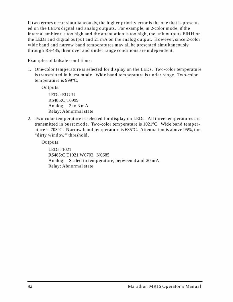
92 Marathon MR1S Operator’s Manual
If two errors occur simultaneously, the higher priority error is the one that is present-ed on the LED’s digital and analog outputs. For example, in 2-color mode, if theinternal ambient is too high and the attenuation is too high, the unit outputs EIHH onthe LEDs and digital output and 21 mA on the analog output. However, since 2-colorwide band and narrow band temperatures may all be presented simultaneouslythrough RS-485, their over and under range conditions are independent.
Examples of failsafe conditions:
1. One-color temperature is selected for display on the LEDs. Two-color temperatureis transmitted in burst mode. Wide band temperature is under range. Two-colortemperature is 999°C.
Outputs:
LEDs: EUUURS485:C T0999Analog: 2 to 3 mARelay: Abnormal state
2. Two-color temperature is selected for display on LEDs. All three temperatures aretransmitted in burst mode. Two-color temperature is 1021°C. Wide band temper-ature is 703°C. Narrow band temperature is 685°C. Attenuation is above 95%, the“dirty window” threshold.
Outputs:
LEDs: 1021RS485:C T1021 W0703 N0685Analog: Scaled to temperature, between 4 and 20 mARelay: Abnormal state

Marathon MR1S Operator’s Manual 93
A.3 CLEANING THE WINDOW
A moderately dirty window will generally not affect the sensor’s accuracy in 2-colormode. However, dirt on the window will affect the 1-color reading. Also, if the win-dow gets too dirty, the sensor cannot detect enough infrared energy to take anaccurage reading, and it will enter a failsafe state. Therefore, regular cleaning of thesensor window is recommended.
Care should be taken when cleaning the window. To clean the window, do the fol-lowing:
1. Lightly blow off loose particles.
2. Gently brush off any remaining particles with a soft camel hair brush or a soft lenstissue (available from camera supply stores).
3. Clean remaining “dirt” using a cotton swab or soft lens tissue dampened in dis-tilled water. Do not scratch the surface.
For finger prints or other grease, use any of the following:
• Denatured alcohol• Ethanol• Kodak® lens cleaner
Apply one of the above to the window. Wipe gently with a soft, clean cloth until yousee colors on the surface, then allow to air dry. Do not wipe the surface dry, this mayscratch the surface.
If silicones (used in hand creams) get on the window, gently wipe the surface withHexane. Allow to air dry.

94 Marathon MR1S Operator’s Manual
A.4 CHANGING THE WINDOW
Sometimes extremely harsh environments can cause damage to the window.Replacement windows are available from the manufacturer. To order replacementwindows, contact your local sales representative or distributor.
To replace the sensor’s window, complete the following:
1. With a very small flat-bladed screw driver (e.g., a jeweler’s screwdriver), pry outthe rubberized Buna-N 70 durometer O-ring. The O-ring is set in a groove in frontof the window.
WARNINGIf you use a fine-bladed knife to remove the O-ring, be careful not tocut or sever the ring.
2. Turn the sensor face down (window pointing down), and the window should fallout.
3. Turn the sensor face up and insert the new window. (Make sure both sides of thewindow are clean.)
4. Replace the O-ring.
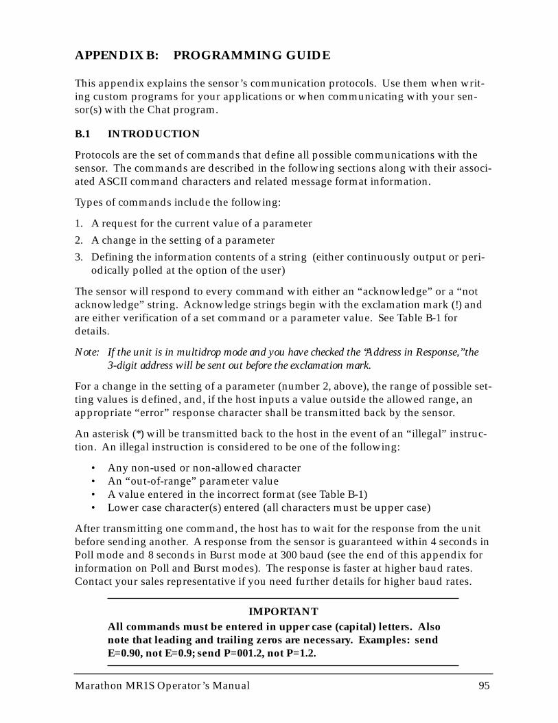
APPENDIX B: PROGRAMMING GUIDE
This appendix explains the sensor’s communication protocols. Use them when writ-ing custom programs for your applications or when communicating with your sen-sor(s) with the Chat program.
B.1 INTRODUCTION
Protocols are the set of commands that define all possible communications with thesensor. The commands are described in the following sections along with their associ-ated ASCII command characters and related message format information.
Types of commands include the following:
1. A request for the current value of a parameter
2. A change in the setting of a parameter
3. Defining the information contents of a string (either continuously output or peri-odically polled at the option of the user)
The sensor will respond to every command with either an “acknowledge” or a “notacknowledge” string. Acknowledge strings begin with the exclamation mark (!) andare either verification of a set command or a parameter value. See Table B-1 fordetails.
Note: If the unit is in multidrop mode and you have checked the “Address in Response,” the3-digit address will be sent out before the exclamation mark.
For a change in the setting of a parameter (number 2, above), the range of possible set-ting values is defined, and, if the host inputs a value outside the allowed range, anappropriate “error” response character shall be transmitted back by the sensor.
An asterisk (*) will be transmitted back to the host in the event of an “illegal” instruc-tion. An illegal instruction is considered to be one of the following:
• Any non-used or non-allowed character• An “out-of-range” parameter value• A value entered in the incorrect format (see Table B-1)• Lower case character(s) entered (all characters must be upper case)
After transmitting one command, the host has to wait for the response from the unitbefore sending another. A response from the sensor is guaranteed within 4 seconds inPoll mode and 8 seconds in Burst mode at 300 baud (see the end of this appendix forinformation on Poll and Burst modes). The response is faster at higher baud rates.Contact your sales representative if you need further details for higher baud rates.
IMPORTANTAll commands must be entered in upper case (capital) letters. Alsonote that leading and trailing zeros are necessary. Examples: sendE=0.90, not E=0.9; send P=001.2, not P=1.2.
Marathon MR1S Operator’s Manual 95
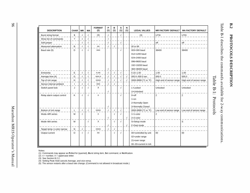
96M
arathon MR
1S Operator’s M
anual
B.2
PR
OT
OC
OL
S D
ES
CR
IPT
ION
Table B-1 d
escribes the comm
ands available for 2-w
ay comm
unications.
Table B-1: Protocols
DESCRIPTION CHARFORMAT
(2)MR MAP(1)
B(1)
S(1) LEGAL VALUES MR FACTORY DEFAULT
Burst string format
Show list of commands
Soft jumper
Measured attenuation
Baud rate (5)
Emissivity
Average time (4)
Top of mA range
Sensor internal ambient
Switch panel lock
Relay alarm output control
Bottom of mA range
Mode–MR series
Mode–MA series
Target temp–1-color narrow
Output current
(3)
00 to 99
003=300 baud
012=1200 baud
024=2400 baud
096=9600 baud
192=19200 baud
384=38400 baud
0.10–1.00
000.0–300.0 sec
0000-9999 (°C or °F)
L=Locked
U=Unlocked
0=off
1=on
2=Normally Open
3=Normally Closed
0000-9999 (°C or °F)
1=1-color
2=2-color
S=Setup mode
F=Fast mode
00=controlled by unit
02=under range
21=over range
00–20=current in mA
UTSI
off
38400
1.00
000.0
High end of sensor range
Unlocked
2
Low end of sensor range
2
00
MA FACTORY DEFAULT
UTEI
off
38400
1.00
000.0
High end of sensor range
Unlocked
2
Low end of sensor range
S
00
$
?
B
D
E
G
H
I
J
K
L
M
M
N
O
√
√
√
√
√
√
√
√
√
√
√
√
√
√
√
√
√
√
√
√
√
√
√
√
√
√
√
√
√
√
√
√
√
√
√
√
√
√
√
√
√
√
√
√
√
√
√
√
√
√
√
√
√
√
√
√
√
√
√
√
√
√
√
√
√
√
√
√
√
√
(3)
nn
nnn
n.nn
nnn.n
nnnn
nnn
X
n
nnnn
n
X
nnnn
nn
N(1)
Notes:(1) Commands may appear as Polled for (queried), Burst string item, Set command, or Notification.(2) n = number, X = uppercase letter.(3) See Section B.2.2.(4) Setting Peak Hold cancels Average, and vice-versa.(5) The sensor restarts after a baud rate change. (Command is not allowed in broadcast mode.)
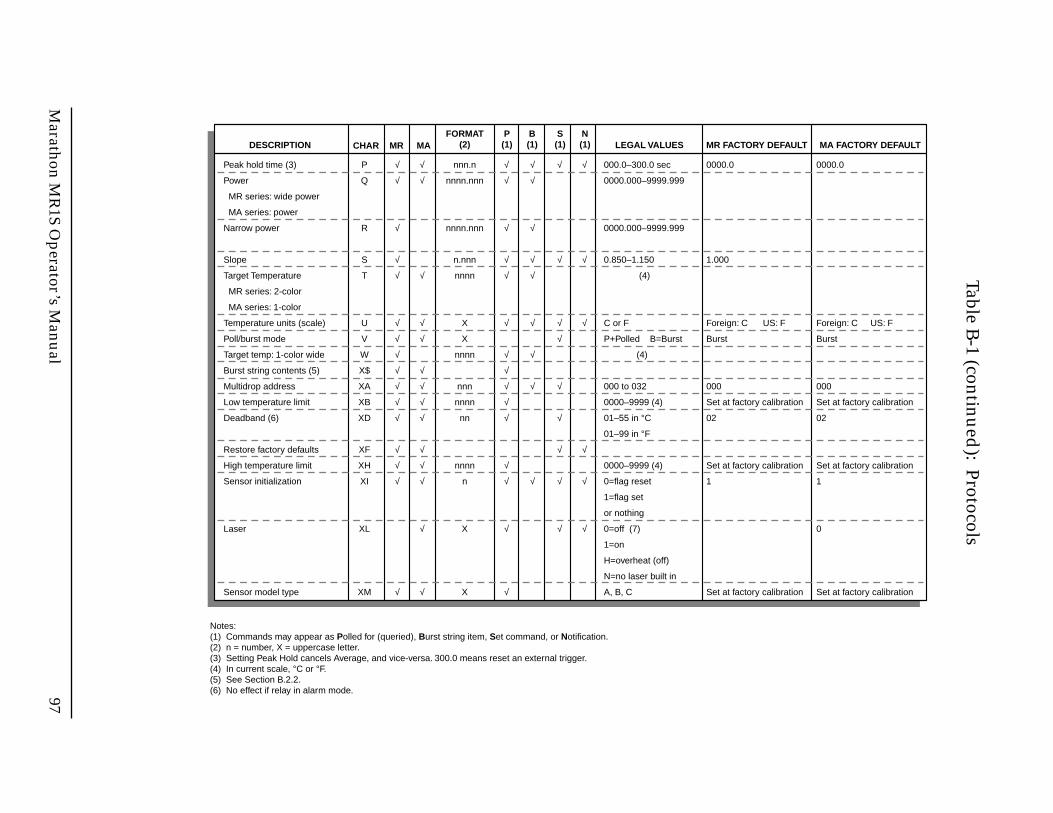
Marathon M
R1S O
perator’s Manual
97
Table B-1 (continued
): Protocols
DESCRIPTION CHARFORMAT
(2)MR MAP(1)
B(1)
S(1) LEGAL VALUES MR FACTORY DEFAULT
Peak hold time (3)
Power
MR series: wide power
MA series: power
Narrow power
Slope
Target Temperature
MR series: 2-color
MA series: 1-color
Temperature units (scale)
Poll/burst mode
Target temp: 1-color wide
Burst string contents (5)
Multidrop address
Low temperature limit
Deadband (6)
Restore factory defaults
High temperature limit
Sensor initialization
Laser
Sensor model type
000.0–300.0 sec
0000.000–9999.999
0000.000–9999.999
0.850–1.150
(4)
C or F
P+Polled B=Burst
(4)
000 to 032
0000–9999 (4)
01–55 in °C
01–99 in °F
0000–9999 (4)
0=flag reset
1=flag set
or nothing
0=off (7)
1=on
H=overheat (off)
N=no laser built in
A, B, C
0000.0
1.000
Foreign: C US: F
Burst
000
Set at factory calibration
02
Set at factory calibration
1
Set at factory calibration
MA FACTORY DEFAULT
0000.0
Foreign: C US: F
Burst
000
Set at factory calibration
02
Set at factory calibration
1
0
Set at factory calibration
P
Q
R
S
T
U
V
W
X$
XA
XB
XD
XF
XH
XI
XL
XM
√
√
√
√
√
√
√
√
√
√
√
√
√
√
√
√
√
√
√
√
√
√
√
√
√
√
√
√
√
√
√
√
√
√
√
√
√
√
√
√
√
√
√
√
√
√
√
√
√
√
√
√
√
√
√
√
√
√
√
√
√
√
√
√
√
√
√
√
√
nnn.n
nnnn.nnn
nnnn.nnn
n.nnn
nnnn
X
X
nnnn
nnn
nnnn
nn
nnnn
n
X
X
N(1)
Notes:(1) Commands may appear as Polled for (queried), Burst string item, Set command, or Notification.(2) n = number, X = uppercase letter.(3) Setting Peak Hold cancels Average, and vice-versa. 300.0 means reset an external trigger.(4) In current scale, °C or °F.(5) See Section B.2.2.(6) No effect if relay in alarm mode.
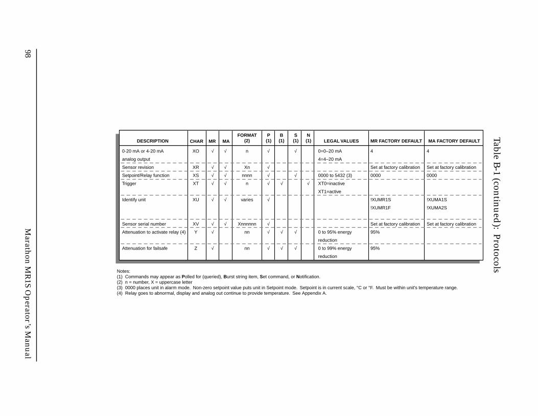
98M
arathon MR
1S Operator’s M
anual
Table B-1 (continued
): Protocols
DESCRIPTION CHARFORMAT
(2)MR MAP(1)
B(1)
S(1) LEGAL VALUES MR FACTORY DEFAULT
0-20 mA or 4-20 mA
analog output
Sensor revision
Setpoint/Relay function
Trigger
Identify unit
Sensor serial number
Attenuation to activate relay (4)
Attenuation for failsafe
0=0–20 mA
4=4–20 mA
0000 to 5432 (3)
XT0=inactive
XT1=active
0 to 95% energy
reduction
0 to 99% energy
reduction
4
Set at factory calibration
0000
!XUMR1S
!XUMR1F
Set at factory calibration
95%
95%
MA FACTORY DEFAULT
4
Set at factory calibration
0000
!XUMA1S
!XUMA2S
Set at factory calibration
XO
XR
XS
XT
XU
XV
Y
Z
√
√
√
√
√
√
√
√
√
√
√
√
√
√
√
√
√
√
√
√
√
√
√
√
√
√
√
√
√
√
n
Xn
nnnn
n
varies
Xnnnnnn
nn
nn
N(1)
Notes:(1) Commands may appear as Polled for (queried), Burst string item, Set command, or Notification.(2) n = number, X = uppercase letter(3) 0000 places unit in alarm mode. Non-zero setpoint value puts unit in Setpoint mode. Setpoint is in current scale, °C or °F. Must be within unit's temperature range.(4) Relay goes to abnormal, display and analog out continue to provide temperature. See Appendix A.
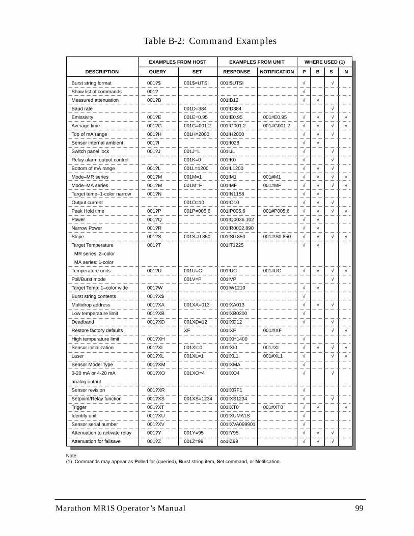
Marathon MR1S Operator’s Manual 99
Table B-2: Command Examples
DESCRIPTION
EXAMPLES FROM HOST
QUERY SET P B S
Burst string format
Show list of commands
Measured attenuation
Baud rate
Emissivity
Average time
Top of mA range
Sensor internal ambient
Switch panel lock
Relay alarm output control
Bottom of mA range
Mode–MR series
Mode–MA series
Target temp–1-color narrow
Output current
Peak Hold time
Power
Narrow Power
Slope
Target Temperature
MR series: 2–color
MA series: 1-color
Temperature units
Poll/Burst mode
Target Temp: 1–color wide
Burst string contents
Multidrop address
Low temperature limit
Deadband
Restore factory defaults
High temperature limit
Sensor initialization
Laser
Sensor Model Type
0-20 mA or 4-20 mA
analog output
Sensor revision
Setpoint/Relay function
Trigger
Identify unit
Sensor serial number
Attenuation to activate relay
Attenuation for failsave
001?$
001?
001?B
001?E
001?G
001?H
001?I
001?J
001?L
001?M
001?M
001?N
001?P
001?Q
001?R
001?S
001?T
001?U
001?W
001?X$
001?XA
001?XB
001?XD
001?XH
001?XI
001?XL
001?XM
001?XO
001?XR
001?XS
001?XT
001?XU
001?XV
001?Y
001?Z
001!$UTSI
001!B12
001!D384
001!E0.95
001!G001.2
001!H2000
001!I028
001!JL
001!K0
001!L1200
001!M1
001!MF
001!N1158
001!O10
001!P005.6
001!Q0036.102
001!R0002.890
001!S0.850
001!T1225
001!UC
001!VP
001!W1210
001!XA013
001!XB0300
001!XD12
001!XF
001!XH1400
001!XI0
001!XL1
001!XMA
001!XO4
001!XRF1
001!XS1234
001!XT0
001!XUMA1S
001!XVA099901
001!Y95
oo1!Z99
001#E0.95
001#G001.2
001#M1
001#MF
001#P005.6
001#!S0.850
001#UC
001#!XF
001#XI
001#XL1
001#XT0
001$=UTSI
001D=384
001E=0.95
001G=001.2
001H=2000
001J=L
001K=0
001L=1200
001M=1
001M=F
001O=10
001P=005.6
001S=0.850
001U=C
001V=P
001XA=013
001XD=12
XF
001XI=0
001XL=1
001XO=4
001XS=1234
001Y=95
001Z=99
√
√
√
√
√
√
√
√
√
√
√
√
√
√
√
√
√
√
√
√
√
√
√
√
√
√
√
√
√
√
√
√
√
√
√
√
√
√
√
√
√
√
√
√
√
√
√
√
√
√
√
√
√
√
√
√
√
√
√
√
√
√
√
√
√
√
√
√
√
√
√
√
√
√
√
√
√
√
√
√
√
√
√
√
√
√
√
√
√
√
√
√
√
√
N
Note:(1) Commands may appear as Polled for (queried), Burst string item, Set command, or Notification.
EXAMPLES FROM UNIT
RESPONSE NOTIFICATION
WHERE USED (1)
100 Marathon MR1S Operator’s Manual
B.2.1 Poll Versus Burst Modes
The interface has two modes of operation: Poll and Burst. Either mode can be select-ed by the host.
Poll: The current value of any individual parameter can be requested by the host.The unit responds once with the value at the selected baud rate. Additionally,the user-defined output string can be polled.
Burst: The unit transmits the user-defined output string (continuously, at the selectedbaud rate), which may contain all of the parameters except for those noted inSection B.2.2. Parameters may also be polled for while the instrument is inburst mode. The poll string will be inserted in the burst-mode stream.
B.2.2 The Burst Mode
The sensor transmits the parameters in a fixed order, regardless of the order in whichthey are specified. This order is as follows:
1. Temperature unit (scale)
2. Target temperature
3. Power
4. Emissivity
5. Peak hold time
6. Average time
7. Mode (Setup/Fast)
8. Internal temperature
9. Temperature setting for 20 mA
10. Temperature setting for 0/4 mA
11. Output current (specified values, in mA, or controlled by sensor)
12. Multidrop address
13. Trigger status
14. Multidrop address
15. Initialization flag

Marathon MR1S Operator’s Manual 101
The following items cannot be placed in the burst output string:
• Poll/Burst Mode• Baud Rate• Manual Lockout/Unlock• Sensor Model Type• Sensor Serial Number• Relay Control• Laser Status• Setpoint• Deadband• Current Output Mode (0–20 mA/4–20 mA)
The following items cannot be polled:
• Poll/Burst Mode• Baud Rate• Relay Control• Set Current Output
An example string for command $=UTQEGH<CR>:
C T1250 Q0400.023 E1.00 G005.5 H1400 <CR><LF>
The default string is as follows: C T1234 E1.00 I025 <CR><LF>
The string for fast mode is as follows: 1234 <CR><LF> (where 1234 is the displayedtemperature)
B.3 REMOTE VERSUS MANUAL CONSIDERATIONS
Since the sensor includes a local user interface, the possibility exists for a person tomake manual changes to parameter settings. To resolve conflicts between inputs tothe sensor, it observes the following rules:
• Command precedence: the most recent parameter change is valid, whetheroriginating from manual or remote.
• If a manual parameter change is made, the sensor will transmit a “notification”string to the host. (Notification strings are supplressed in multidrop mode.)(See examples in Table B-2.)
• A manual lockout command is available in the protocols set so the host canrender the user interface “display only,” if desired.
All parameters, except for Relay Control and Set Current Output, set via the 2-wayinterface are retained in the sensor’s nonvolatile memory.
Note: When a unit is placed in multidrop mode its manual user interface is automaticallylocked.
102 Marathon MR1S Operator’s Manual
B.4 RESPONSE TIME IN SETUP MODE
The analog output response time is not guaranteed while a parameter value is beingchanged or if there is a continuous stream of commands from the host.
The digital response time specifies how quickly the unit can report a temperaturechange via RS-485 in burst mode. (Digital response time is not defined for polledmode.) The digital response time is defined as the time that elapses between a changein target temperature and the transmission of a burst string reporting the new temper-ature. Actual digital response time can vary from one reading to the next, so the digi-tal response time is defined as the “average digital response time.”
The average digital response time depends on the number of characters requested inthe output string and with the baud rate. It may be computed as the following:
n X 15000t = 9.9 + __________
b
where
t = average digital response time in msn = the number of characters in the string, including <CR> and <LF>b = the baud rate
Example:
With a baud rate of 38400, and an output string containing temperature units, 2-colortemperature, emissivity, and ambient (20 characters), the average digital responsetime would be the following:
20 X 15000t = 9.9 + __________
38400
= 17.7 ms
Note that the analog output response time is not affected by baud rate or the numberof characters transmitted in the burst string.

Marathon MR1S Operator’s Manual 103
APPENDIX C: SLOPE AND EMISSIVITY
Slope is the ratio of 1-color wideband emissivity to 1-color narrow emissivity and isused in the calculation of 2-color temperature. Since there is no way to adjust 1-colornarrow emissivity in the instrument, the temperature algorithm derives it by dividing1-color wide emissivity by slope.
Therefore, if the user needs to look at the narrowband temperature, care should betaken in adjusting slope and wideband emissivity in such a way that narrow bandemissivity is calculated to be greater than 1.00 (or less than 0.10).
Emissivity is the measure of an object’s ability to emit infrared energy. It can be avalue from 0 (shiny mirror) to 1.0 (blackbody). If a higher than actual emissivityvalue is set, the sensor’s output will read low. For example, if 0.95 is set, and the actu-al emissivity is 0.9, the reading will show lower than the true temperature.
HOW TO DETERMINE SLOPE
The most effective way to determine and adjust the slope is to take the temperature ofthe material using a probe sensor such as an RTD, thermocouple, or other suitablemethod. Once you determine the actual temperature, adjust the slope setting until thesensor’s temperature reads the same as the actual temperature reading. This is thecorrect slope for the measured material.
HOW TO DETERMINE EMISSIVITY
If you cannot find the emissivity of a material in Table B-1, it can be determined byone of the following methods, in order of preference:
1. Determine the actual temperature of the material using a sensor such as an RTD,thermocouple or other suitable method. Adjust the emissivity setting until thesensor’s temperature reading is the same as the actual temperature reading. Thisis the correct emissivity for the measured material.
2. If a portion of the surface of the object can be coated, use a flat black paint (notsemi-gloss or gloss), which will have an emissivity of about 0.98. Next, measurethe painted area using an emissivity setting of 0.98. Finally, measure an adjacentarea on the object, and adjust the emissivity setting until the same temperature isreached. This is the correct emissivity for the measured material.

104 Marathon MR1S Operator’s Manual
TYPICAL EMISSIVITY VALUES
Table B-1 is a reference for determining the emissivity of various metals. Table B-2 is areference for non-metals. Emissivity values shown in the table are only approximate,since several parameters may affect the emissivity of an object. These include temper-ature, angle of measurement, geometry (plane, concave, convex, etc.), thickness, sur-face quality (polished, rough, oxidized, sandblasted), spectral region of measurement,and transmissivity (i.e., thin film plastics).
Table B-1: Typical Emissivity Values for Metals
AluminumUnoxidized 0.1-0.2Oxidized 0.4Roughened 0.2-0.8Polished 0.1-0.2
BrassPolished 0.1-0.3Oxidized 0.6
Chromium 0.4Copper
Polished 0.05Roughened 0.05-0.2Oxidized 0.2-0.8
Gold 0.3Haynes
Alloy 0.5-0.9Inconel
Oxidized 0.4-0.9Sandblasted 0.3-0.4Electropolished 0.2-0.5
IronOxidized 0.4-0.8Unoxidized 0.35Molten 0.35
Iron, CastOxidized 0.7-0.9Unoxidized 0.35Molten 0.35
Iron, WroughtDull 0.9
LeadPolished 0.35Rough 0.65
Magnesium 0.3-0.8Molybdenum
Oxidized 0.5-0.9Unoxidized 0.25-0.35
Monel (Ni-Cu) 0.3Nickel
Oxidized 0.8-0.9Electrolytic 0.2-0.4
Silver 0.04Steel
Cold-Rolled 0.8-0.9Polished Sheet 0.35Molten 0.35Oxidized 0.8-0.9Stainless 0.35
Tin (Unoxidized) 0.25Titanium
Polished 0.5-0.75Tungsten
Polished 0.35-0.4Zinc
Oxidized 0.6Polished 0.5
MATERIAL MATERIALEMISSIVITY EMISSIVITY
1.0µm 1.0µm
MATERIAL EMISSIVITY
1.0µm
Asbestos 0.9Carbon
Unoxidized 0.8-0.95Graphite 0.8-0.9
Ceramic 0.4Concrete 0.65
Table B-2: Typical Emissivity Values for Non-Metals
Marathon MR1S Operator’s Manual 105
To optimize surface temperature measurements consider the following guidelines:
1. Determine the object emissivity using the instrument used for the measurement.
2. Avoid reflections. Shield the object from surrounding high temperature sources.
3. For higher temperature objects, use shorter wavelength instruments wheneveroverlap occurs.
4. For semi-transparent materials such as glass, make sure that the background isuniform and lower in temperature than the object.
5. Mount the sensor perpendicular to the target surface whenever emissivity is lessthan 0.9. Note that in all cases, do not mount the sensor at angles exceeding 45degrees from perpendicular.

106 Marathon MR1S Operator’s Manual

Marathon MR1S Operator’s Manual 107
APPENDIX D: DIN CONNECTOR WIRING
If you need to wire a new DIN connector or rewire the supplied connector, refer to thefollowing illustration and table for the wiring layout.
AB K
NL
C
D
E F G
H
J
M
Figure D-1: DIN Connector Pin Layout (Pin Side)
Table D-1: DIN Connector Wiring
PIN
A
B
C
D
E
F
G
H
J
K
L
M
N
COLOR
Black *
White *
Grey *
Purple *
White/Drain
Yellow
Orange
Blue
Green
Brown
Black
Red
No Connection
DESCRIPTION
Rx A
Rx B
Tx B
Tx A
Shield
Relay NC
Relay COM
Relay NO
+ mA Out
– mA Out
Power Ground
+ 24 VDC
N/A
* Note: Twisted Pairs — Black & White— Grey & Purple

108 Marathon MR1S Operator’s Manual
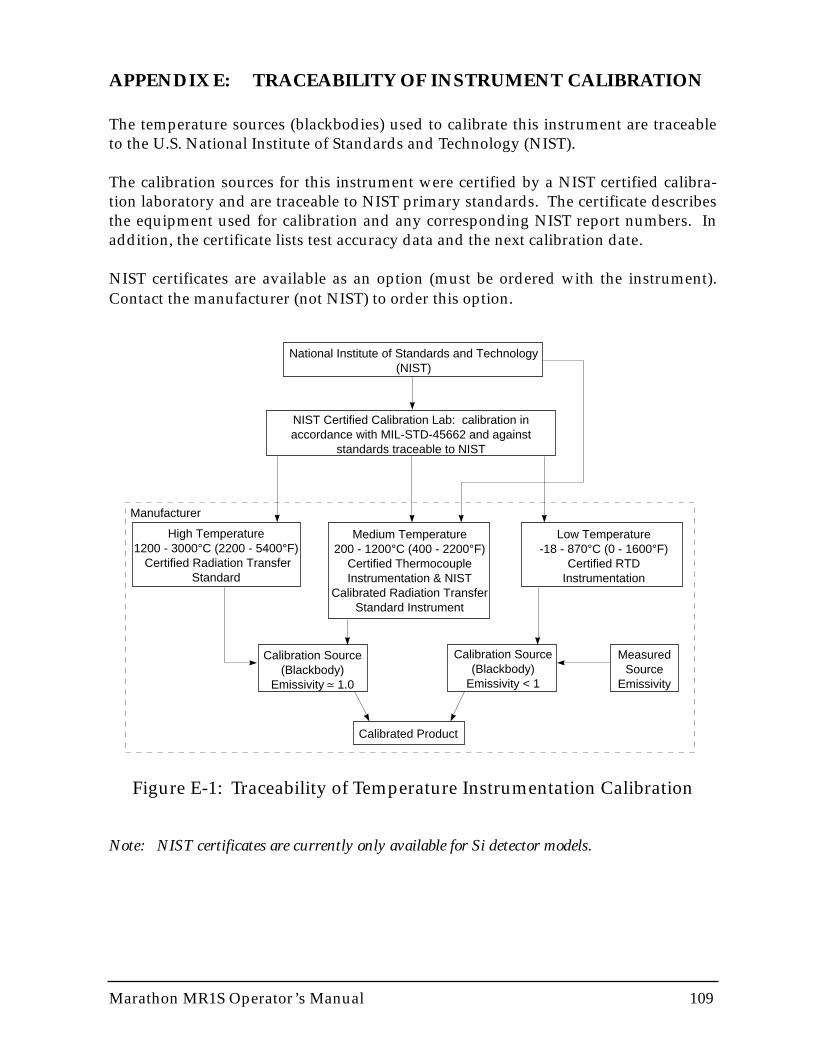
Marathon MR1S Operator’s Manual 109
APPENDIX E: TRACEABILITY OF INSTRUMENT CALIBRATION
The temperature sources (blackbodies) used to calibrate this instrument are traceableto the U.S. National Institute of Standards and Technology (NIST).
The calibration sources for this instrument were certified by a NIST certified calibra-tion laboratory and are traceable to NIST primary standards. The certificate describesthe equipment used for calibration and any corresponding NIST report numbers. Inaddition, the certificate lists test accuracy data and the next calibration date.
NIST certificates are available as an option (must be ordered with the instrument).Contact the manufacturer (not NIST) to order this option.
National Institute of Standards and Technology(NIST)
NIST Certified Calibration Lab: calibration in accordance with MIL-STD-45662 and against
standards traceable to NIST
High Temperature1200 - 3000°C (2200 - 5400°F)
Certified Radiation Transfer Standard
Medium Temperature200 - 1200°C (400 - 2200°F)
Certified ThermocoupleInstrumentation & NIST
Calibrated Radiation TransferStandard Instrument
Low Temperature-18 - 870°C (0 - 1600°F)
Certified RTDInstrumentation
Calibration Source(Blackbody)
Emissivity 1.0
Calibration Source(Blackbody)
Emissivity < 1
MeasuredSource
Emissivity
Calibrated Product
Manufacturer
Figure E-1: Traceability of Temperature Instrumentation Calibration
Note: NIST certificates are currently only available for Si detector models.

110 Marathon MR1S Operator’s Manual

Marathon MR1S Operator’s Manual 111
APPENDIX F: CE CONFORMITY FOR THE EUROPEAN COMMUNITY
This instrument conforms to the following standards:
• EN50081-2 Emission Standard
• EN50082-2 Immunity Standard

112 Marathon MR1S Operator’s Manual
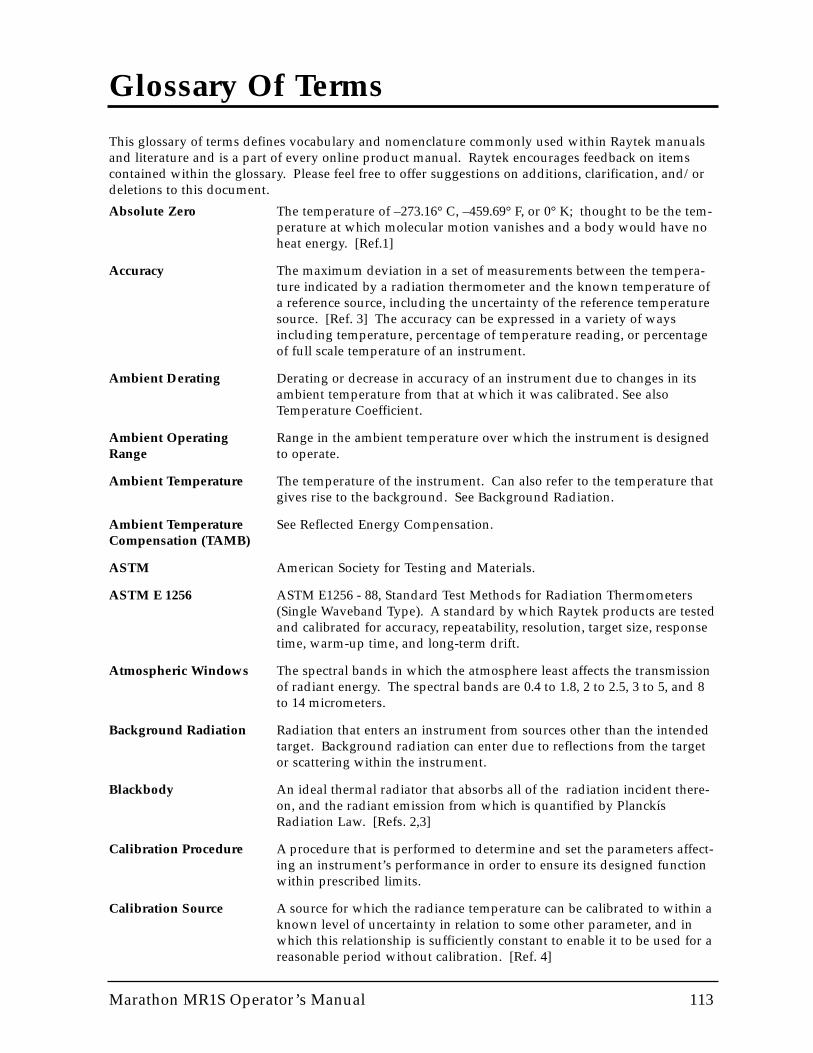
Marathon MR1S Operator’s Manual 113
Glossary Of Terms
This glossary of terms defines vocabulary and nomenclature commonly used within Raytek manualsand literature and is a part of every online product manual. Raytek encourages feedback on itemscontained within the glossary. Please feel free to offer suggestions on additions, clarification, and/ordeletions to this document.
Absolute Zero The temperature of –273.16° C, –459.69° F, or 0° K; thought to be the tem-perature at which molecular motion vanishes and a body would have noheat energy. [Ref.1]
Accuracy The maximum deviation in a set of measurements between the tempera-ture indicated by a radiation thermometer and the known temperature ofa reference source, including the uncertainty of the reference temperaturesource. [Ref. 3] The accuracy can be expressed in a variety of waysincluding temperature, percentage of temperature reading, or percentageof full scale temperature of an instrument.
Ambient Derating Derating or decrease in accuracy of an instrument due to changes in itsambient temperature from that at which it was calibrated. See alsoTemperature Coefficient.
Ambient Operating Range in the ambient temperature over which the instrument is designed Range to operate.
Ambient Temperature The temperature of the instrument. Can also refer to the temperature thatgives rise to the background. See Background Radiation.
Ambient Temperature See Reflected Energy Compensation.Compensation (TAMB)
ASTM American Society for Testing and Materials.
ASTM E 1256 ASTM E1256 - 88, Standard Test Methods for Radiation Thermometers(Single Waveband Type). A standard by which Raytek products are testedand calibrated for accuracy, repeatability, resolution, target size, responsetime, warm-up time, and long-term drift.
Atmospheric Windows The spectral bands in which the atmosphere least affects the transmissionof radiant energy. The spectral bands are 0.4 to 1.8, 2 to 2.5, 3 to 5, and 8to 14 micrometers.
Background Radiation Radiation that enters an instrument from sources other than the intendedtarget. Background radiation can enter due to reflections from the targetor scattering within the instrument.
Blackbody An ideal thermal radiator that absorbs all of the radiation incident there-on, and the radiant emission from which is quantified by PlanckísRadiation Law. [Refs. 2,3]
Calibration Procedure A procedure that is performed to determine and set the parameters affect-ing an instrument’s performance in order to ensure its designed functionwithin prescribed limits.
Calibration Source A source for which the radiance temperature can be calibrated to within aknown level of uncertainty in relation to some other parameter, and inwhich this relationship is sufficiently constant to enable it to be used for areasonable period without calibration. [Ref. 4]
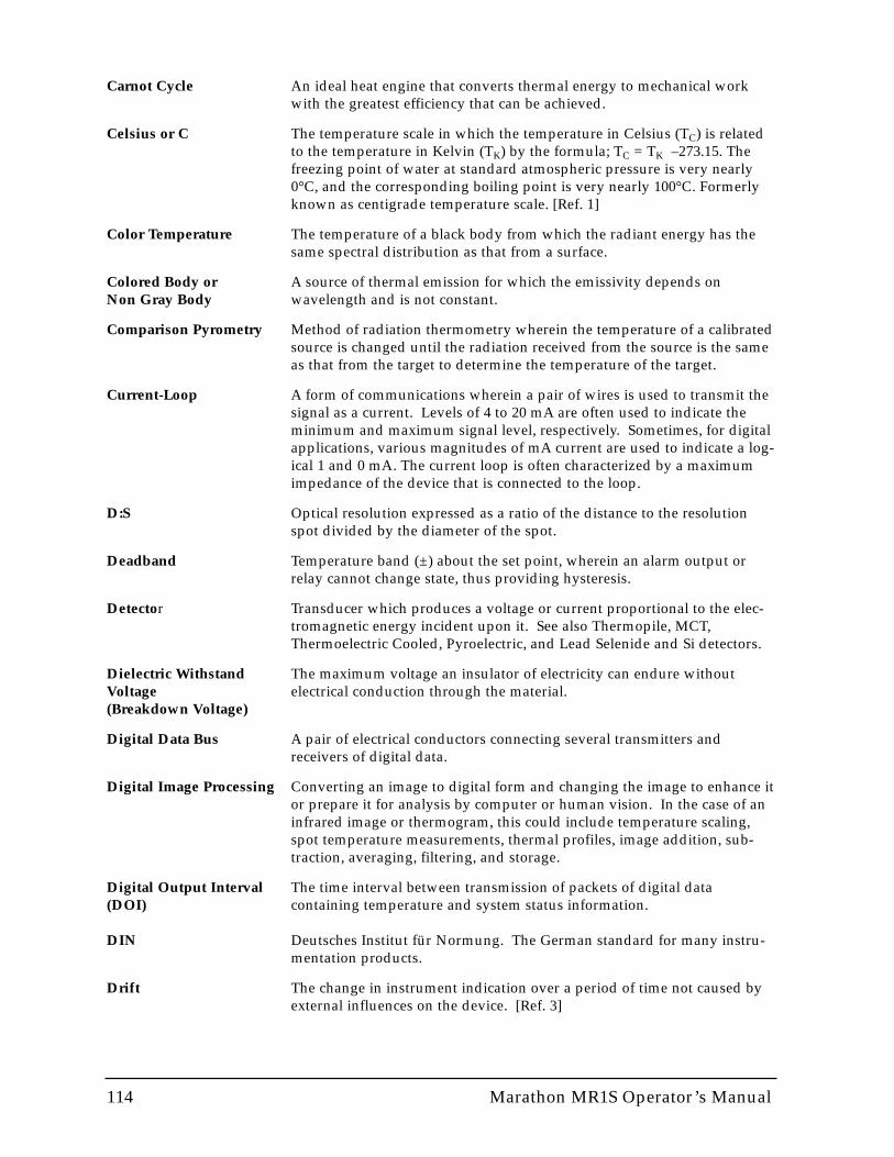
114 Marathon MR1S Operator’s Manual
Carnot Cycle An ideal heat engine that converts thermal energy to mechanical workwith the greatest efficiency that can be achieved.
Celsius or C The temperature scale in which the temperature in Celsius (TC) is relatedto the temperature in Kelvin (TK) by the formula; TC = TK –273.15. Thefreezing point of water at standard atmospheric pressure is very nearly0°C, and the corresponding boiling point is very nearly 100°C. Formerlyknown as centigrade temperature scale. [Ref. 1]
Color Temperature The temperature of a black body from which the radiant energy has thesame spectral distribution as that from a surface.
Colored Body or A source of thermal emission for which the emissivity depends on Non Gray Body wavelength and is not constant.
Comparison Pyrometry Method of radiation thermometry wherein the temperature of a calibratedsource is changed until the radiation received from the source is the sameas that from the target to determine the temperature of the target.
Current-Loop A form of communications wherein a pair of wires is used to transmit thesignal as a current. Levels of 4 to 20 mA are often used to indicate theminimum and maximum signal level, respectively. Sometimes, for digitalapplications, various magnitudes of mA current are used to indicate a log-ical 1 and 0 mA. The current loop is often characterized by a maximumimpedance of the device that is connected to the loop.
D:S Optical resolution expressed as a ratio of the distance to the resolutionspot divided by the diameter of the spot.
Deadband Temperature band (±) about the set point, wherein an alarm output orrelay cannot change state, thus providing hysteresis.
Detector Transducer which produces a voltage or current proportional to the elec-tromagnetic energy incident upon it. See also Thermopile, MCT,Thermoelectric Cooled, Pyroelectric, and Lead Selenide and Si detectors.
Dielectric Withstand The maximum voltage an insulator of electricity can endure without Voltage electrical conduction through the material.(Breakdown Voltage)
Digital Data Bus A pair of electrical conductors connecting several transmitters andreceivers of digital data.
Digital Image Processing Converting an image to digital form and changing the image to enhance itor prepare it for analysis by computer or human vision. In the case of aninfrared image or thermogram, this could include temperature scaling,spot temperature measurements, thermal profiles, image addition, sub-traction, averaging, filtering, and storage.
Digital Output Interval The time interval between transmission of packets of digital data (DOI) containing temperature and system status information.
DIN Deutsches Institut für Normung. The German standard for many instru-mentation products.
Drift The change in instrument indication over a period of time not caused byexternal influences on the device. [Ref. 3]
Marathon MR1S Operator’s Manual 115
EMI/RFI Electro-Magnetic Interference/Radio Frequency Interference, whichaffects the performance of electronic equipment.
Emissivity At a given wavelength the ratio of infrared energy radiated by an object ata given temperature to that emitted by a blackbody at the same tempera-ture The emissivity of a blackbody is unity at all wavelengths.
Environmental Rating A rating given (usually by agencies and regulatory bodies) to indicate theseverity of the environment in which the unit will function reliably.
External Reset (Trigger) Initialization of an instrument to its state at power up including signalconditioning features (Peak Hold, Valley Hold, Sample Hold, Average, 1-way RS232, etc.) via the external reset input.
Fahrenheit or F Temperature measurement scale where, at standard atmospheric pressure,the freezing point of water is 32°F and the vaporization point of water is212°F. To convert from Celsius, use F = (C x 1.8) + 32.
Fail-Safe Operation A feature designed to alert the operator via display, and to bring a processto a safe shutdown via output, in the event of a particular control systemor process failure.
Far Field A measurement distance sufficiently large (typically greater than 10 timesthe focal distance) whereby the spot size of an instrument is growing indirect proportion to the distance from the instrument, and the field ofview is constant.
Field of View (FOV) The area or solid angle viewed through an optical or infrared instrument .Typically expressed by giving the spot diameter of an instrument and thedistance to that spot. Also expressed as the angular size of the spot at thefocal point. See Optical or Infrared Resolution.
Focal Point or Distance The point or distance from the instrument at which the object is focusedonto the detector within the instrument. The focal point is the place ordistance at which the optical or infrared resolution is greatest.
Full Scale Accuracy The temperature measurement accuracy expressed as a percentage of themaximum possible reading of an instrument.
Gray Body A source of radiant emissions for which the emissivity is less than 1 butconstant and, therefore, independent of wavelength.
IEC International Electrotechnical Commission. A European organization thatcoordinates and sets related standards among the European Community.
IEEE-488 A standard developed by Hewlett-Packard Corporation and adopted bythe IEEE for digital interface between programmable instrumentation. Ituses a 16-bit bus to interconnect up to 15 instruments. The standard com-prises hardware and protocol options. It is also called the Hewlett-Packard Interface Bus (HPIB) or General Purpose Interface Bus (HPIB) orGeneral Purpose Interface Bus (GPIB). The present standard isANSI/IEEE-4881-1987.
IFOV (Instantaneous Instantaneous Field of View is the angular resolution of an imaging Field of View) instrument that is determined by the size of the detector and the lens. For
a point instrument the IFOV and FOV are the same.

116 Marathon MR1S Operator’s Manual
Image Processing Converting an image to a digital form and further enhancing the image toprepare it for computer or visual analysis. In the case of an infraredimage or thermogram, this could include temperature scaling, spot tem-perature measurements, and thermal profiles, as well as image addition,subtraction, averaging, filtering, and storage.
Indium Antimonide (InSb) A material used to construct photon detectors that are sensitive in thespectral region from 2.0 to 5.5 µm and used in infrared scanners andimagers. These detectors require cryogenic cooling.
Infrared Radiation (IR) Radiation within the portion of the electromagnetic spectrum whichextends from 0.75 to 1000 µm.
Infrared or Optical Filter See Spectral Filter or Neutral Density Filter.
Infrared Thermometer An instrument that determines the temperature of an object by means ofdetecting and quantifying the infrared radiation emitted therefrom. Typesinclude total power, wide band, narrow band, and multiple wavelengths.
Insulation Resistance The property of a material to resist the flow of electrical current andexpressed in Megohms (M ) as the ratio of an applied electrical potentialdivided by the flow of electrical current resulting therefrom.
Interchangeability The ability for a head sensor to be interchanged with another of the same(of heads) type without the need to recalibrate the system (also referred to as
Universal Electronics). Some monitors support the interchangeability ofdifferent types of heads.
Intrinsically Safe A standard for preventing explosions in hazardous areas by limiting theelectrical energy available to levels that are insufficient to cause ignition ofexplosive atmospheres during normal operation of an instrument.
IP Designation Grades of intrinsic safety protection pertaining to enclosures per theBritish Standard 4752. The type of protection is defined by two digits, thefirst relating to accessibility and the second to environmental protection.The two numbers are preceded by the letters IP. [Ref. 6]
Isolated Inputs, Outputs Inputs, outputs and power supply lines that are electrically insulatedor Power Supplies from each other, whereby arbitrary grounding of these lines cannot affect
the performance of the instrument such as generate ground-loops or shortout internal resistors.
Isotherm A continuous line (not necessarily straight or smooth) on a surface (orchart) comprising points of equal or constant temperature.
JIS Japanese Industrial Standard. A technical governing body that sets stan-dards for determining or establishing the accuracy of IR thermometers.
Kelvin or K A temperature scale that is directly related to the heat energy within abody. Formally, a temperature scale in which the ratio of the tempera-tures of two reservoirs is equal to the ratio of the amount of heat absorbedfrom one of the them by a heat engine operating in a Carnot Cycle to theamount of heat rejected by this engine to the other reservoir. The temper-ature of the triple point of water (in this scale) is defined as 273.16° K.[Ref. 1] To convert from Celsius, K=C+273.16.
Lead Selenide (PbSe) A material used to make photon detectors that are sensitive in the 3 to 5µm spectral band. These detectors require thermoelectric cooling and areused in IR thermometers, scanners, and imagers.

Marathon MR1S Operator’s Manual 117
Maximum Current Describes the size of a load that can be driven by an instrument with aLoop Impedance mA output. For example a 500 ohm maximum loop impedance means
that the instrument can supply 10 volts at 20 mA into this load.
MCT (Mercury Cadmium A ternary alloy material used to build photon detectors that are sensitive Telluride) or HgCdTe in the 3-5µm and 8-14µm regions of the spectrum and require TE cooling
in the 3-5 µm region and cryogenic cooling in the 8-14µm region.
Minimum spot size The diameter of the smallest object for which an instrument can meet itsperformance specifications.
NEMA National Electrical Manufacturer’s Association. Among its activities, setsUS standards for housing enclosures, similar to IEC IP.
NET See NETD.
NETD (or NE³T) Noise Equivalent Temperature Difference or the change in temperature ofa blackbody target that fills the radiometer FOV which results in a changein the radiometer signal equal to the rms noise of the instrument.
Neutral Density Filter An optical or infrared filter for which the transmission is constant and nota function or wavelength.
NIST Traceability Calibration in accordance with and against standards traceable to NIST(National Institute of Standards and Technology, USA). Traceability toNIST is a means of ensuring that reference standards remain valid andtheir calibration remains current.
Optical or Infrared The ratio of the distance to the target divided by the diameter of the Resolution circular area (or spot) for which the energy received by the thermometer
is a specified percentage of the total energy that would be collected by aninstrument viewing a calibration source at the same temperature. Thedistance to the target is generally the focal distance of the instrument.The percentage energy is generally 90% to 95%.
Optical Pyrometer A system that, by comparing a source whose temperature is to be mea-sured to a standardized source of illumination (usually compared to thehuman eye), determines the temperature of the former source.
Output Impedance Describes the impedance of the thermometer that is experienced by anydevice connected thereto. To achieve accurate readings, the input imped-ance of a device connected to the thermometer must be much greater thanthe output impedance of the thermometer.
Peak Hold Output of the maximum temperature measurement indicated by aninstrument during the time duration for which this display mode hasbeen active.
Photondetector or A type of detector in which the photons or quanta of energy interact Quantum Detector directly with the detector to generate a signal.
Pyroelectric Detector Thermal detector that has a signal generated by means of the pyroelectriceffect wherein changes in temperature of the detector generates an electri-cal signal.
Pyrometer A broad class of temperature measuring devices. They were originallydesigned to measure high temperature, but some are now used in anytemperature range. Includes radiation pyrometers, thermocouples, resis-tance pyrometers, and thermistors.
118 Marathon MR1S Operator’s Manual
Radiance Temperature The temperature of a black body which has a radiance equal to the radi-ance of the object at a particular wavelength or wavelength band. [Ref. 5]
Radiant Energy The electromagnetic energy emitted by an object due to its temperature.
Radiation Thermometer A device used to measure the temperature of an object by quantificationof the electromagnetic radiation emitted therefrom. Also, a radiometercalibrated to indicate a blackbody’s temperature. [Ref. 3]
Rankine or R The absolute temperature scale related to Fahrenheit in the equivalentmanner Kelvin is to Celsius. R = 1.8 x K, or also R = F + 459.67.
Reference Junction Refers to the thermocouple junction that must be known in order to inferor Cold Junction the temperature of the other or thermocouple measurement junction.
Reflectance The ratio of the radiant energy reflected from a surface to that incident onthe surface.
Reflected Energy Feature used to achieve greater accuracy by compensating for back-Compensation ground IR energy that is reflected off the target into the instrument. If the
temperature of the background is known, the instrument reading can becorrected by using this feature.
Relative Humidity The dimensionless ratio of the actual vapor pressure of the air to the satu-ration vapor pressure (abbreviated RH). Percent relative humidity isexpressed as the product of RH and 100. For example an RH of 0.30 is apercent relative humidity of 30%. [Ref. 1]
Repeatability The degree to which a single instrument gives the same reading on thesame object over successive measures under the same ambient and targetconditions. The ASTM standard E 1256 defines it as the sample standarddeviation of twelve measurements of temperature at the center of thespan of the instrument. Generally expressed as a temperature differenceor a percent of full scale value, or both. [Ref. 3]
Resolution See Temperature Resolution, Optical Resolution, or Spatial Resolution.
Response Time The time for an instrument’s output to change to 95% of its final valuewhen subjected to an instantaneous change in target temperature corre-sponding to the maximum temperature the instrument can measure (perASTM E 1256). The average time required for software computation with-in the processor is also included in this specification for Raytek products.
RS-232 Recommended Standard (RS) 232 is a standard developed by theElectronic Industries Association (EIA) that governs the serial communi-cations interface between data processing and data communicationsequipment and is widely used to connect microcomputers to peripheraldevices. [Ref. 1] The present revision is EIA-RS-232-D, which defines theinterface between Data Terminal Equipment (DTE) and DataCommunications Equipment (DCE) employing serial binary data inter-change. The standard does not define the protocol or format of the binarystream. The standard comprises three parts: electrical characteristics,interface mechanical characteristics, and functional description of theinterchange circuits. The equivalent international standard is ComiteConsultatif International Telegraphique et Telephonique (CCITT) V.24.
RS-422 A recommended standard developed by EIA that defines a balanced inter-face and is an expansion of RS-423 that increases the data rate to 10 Mbps.see RS-423
Marathon MR1S Operator’s Manual 119
RS-423 A recommended standard developed by EIA that defines an unbalancedinterface and is an expansion of RS-232 and provides improvementsincluded increased connecting cable lengths, increased data rates, and useof multiple receivers on line.
RS-485 A recommended standard developed by EIA that is an improvement overRS-422 in that it allows an increase in the number of receivers and trans-mitters permitted on the line.
RTD Resistance Temperature Device. A contact measurement device whoseresistance varies with temperature.
Sample Hold A temperature taken from a target and displayed or held for a set periodof time or until the next external reset occurs.
Scatter Radiant energy reaching the detector of an instrument from the back-ground other than that which is reflected from the target.
Set Point Process or measurement variable setting which when crossed by the mea-sured value will trigger an event and/or cause a relay to change state.
Shock Test An impact test where an object or test unit is subjected to an impulsiveforce which is capable of exciting mechanical resonances of vibration.
Signal Processing Manipulation of temperature data for purposes of enhancing the data.Examples of signal processing functions include Peak Hold, Valley Hold,and Averaging.
Silicon (Si) Detector A photon detector used in measurement of high temperatures.
Size-of-Source Effect The effect by which the energy collected by, and temperature reading of,an instrument continues to increase as the size of a target increasesbeyond the field-of-view of the instrument. It is caused by two occur-ances: the remaining energy above the percentage used to define locationand scattering of radiation as it enters the instrument such that energyfrom outside the FOV of the instrument enters it. The existence of thiseffect means that the accuracy of the instrument may be affected by tar-gets that are too large as well as two small. This effect is also called TargetSize Effect. [ASTM STP 895]
Slope The ratio of the emissivities for the two spectral bands of a 2-colorradiometer. The emissivity of the shorter wavelength band is divided bythe emissivity of the longer wavelength band. Slope can be greater than,equal to, or less than unity. Slope accounts for materials where emissivityvaries with wavelength.
Spectral Filter An optical or infrared element used to spectrally limit the transmission ofradiant energy reaching an instrument’s detector.
Spectral Response The wavelength region in which the IR Thermometer is sensitive.
Spot The diameter of the area on the target where the temperature determina-tion is made. The spot is defined by the circular aperture at the targetwhich allows typically 90% of the IR energy from the target to be collectedby the instrument. See also Size-of-Source Effect.
120 Marathon MR1S Operator’s Manual
Stare or Lag A saturation effect whereby the signal from an instrument enduresbeyond the response time after the target has been removed from the fieldof view. Can be caused by exposing the sensor to a target of high temper-ature for an extended period. The effect is expressed as the increase inresponse time required for the sensor to return to within 5% of the correctreading.
Storage Temperature The ambient temperature range an instrument can survive in a non-oper-Range ating mode and perform within specifications when operated.
Target The object upon which the temperature is determined.
Target Size Effect See Size-of-Source Effect.
Temperature A property of an object which determines the direction of heat flow whenthe object is placed in thermal contact with another object (i.e., heat flowsfrom a region of higher temperature to one of lower temperature). [Ref. 1]
Temperature Coefficient The change in accuracy of an instrument with changes in ambient temper-ature from that at which the instrument was calibrated. Usually expressedas the percent change in accuracy (or additional error in degrees) perchange in ambient temperature. For a rapid change in ambient condi-tions, refer to Thermal Shock.
Temperature Resolution The minimum simulated or actual change in target temperature that givesa usable change in output and/or indication. [Ref. 3]
Temporal Drift The change in accuracy of an instrument over time. This effect may bedue to aging of the instrument’s components or calibration changes.
Thermal Detector Detector in which the photons of incident radiation are converted to heatand then into a signal from the detector. Thermal detectors include pyro-electric, bolometer, and thermopile types.
Thermal Drift See Temperature Coefficient.
Thermal Radiator An object that emits electromagnetic energy due to its temperature.
Thermal Shock An error due to a rapid change in the ambient temperature of an instru-ment. Expressed as a maximum error and the time required for perfor-mance to return to prescribed specifications.
Thermistor A semiconductor material whose resistivity changes with temperature.
Thermocouple A set of two junctions of two dissimilar metals used to measure tempera-ture by means of the Peltier effect, whereby heat is liberated or absorbedby the flow of electrical current through a junction of two dissimilar met-als such that an electrical potential develops between two such junctionsin proportion to the difference in temperature of the junctions. A vari-ety of types exist including:
J (Fe / constantan) K (chromel / alumel)T (Cu / constantan) E (chromel / constantan)R (Pt / Pt - 30% Rh) S (Pt / Pt -10% Rh)B (Pt - 6% Rh / Pt - 30% Rh) G (W / W - 26% Re)C (W - 5% Re / W - 26% Re) D (W - 3% Re / W - 25% Re)
Marathon MR1S Operator’s Manual 121
Thermoelectric (TE) Cooling based on the Peltier effect. An electrical current is sent through Cooling two junctions of two dissimilar metals. One junction will grow hot while
the other will grow cold. Heat from the hot junction is dissipated to theenvironment, and the cold from the other junction is used to cool. [Ref. 1]
Thermogram A thermal photograph generated by scanning an object or scene. [Ref. 1]
Thermopile A number of similar thermocouples connected in series, arranged so thatalternate junctions are at the reference temperature and at the measuredtemperature, to increase the output for a given temperature differencebetween reference and measuring junctions. [Ref. 2]
Time Constant The time it takes for a sensing element to respond to 63.2% of a stepchange at the target.
Transfer Standard A precision radiometric measurement instrument with NIST traceable cal-ibration in the USA (with other recognized standards available for inter-national customers), used to calibrate radiation reference sources.
Transmittance The ratio of IR radiant energy incident on an object to that exiting theobject.
Triple Point The condition of temperature and pressure under which the gaseous, liq-uid, and solid phases of a substance can exist in equilibrium. For water atatmospheric pressure, this is typically referred to as its freezing point.
Two-Color Thermometry A technique that measures the energy in two different wavelength bands(colors) in order to determine temperature. The 2 color technique hasbeen shown to be effective for correcting errors due to partial blockage ofthe target caused by dust particles.
Valley Hold Output of the minimum temperature measurement indicated by aninstrument during the time duration for which this display mode hasbeen active.
Verification Confirmation of a design with regard to performance within all pre-scribed specifications.
Vibration Test A test where oscillatory or repetitive motion is induced in an object (asper MIL-STD-810 or IEC 68-2-6), which is specified as an acceleration ing’s and power spectral density (PSD), after which the unit is tested forproper operation.
Warm-Up Time Time, after turn on, until the instrument will function within specifiedrepeatability. [Ref. 3]
122 Marathon MR1S Operator’s Manual
REFERENCES
1. McGraw-Hill Dictionary of Scientific and Technical Terms, Fifth Edition, McGraw-Hill, Inc., 1994.
2. Compilation of ASTM Standard Definitions, Eighth Edition, ASTM, 1994.
3. ASTM E1256 - 88, Standard Test Methods for Radiation Thermometers (Single Waveband Type),ASTM, 1988.
4. ASTM STP 895, Applications of Radiation Thermometry,, Richmond and DeWitt, ASTM, 1984.
5. General Rules for Expression of the Performance of Radiation Thermometers, Japanese IndustrialStandard, JIS C 1612, 1988.
6. Intrinsically Safe Instrumentation - A Guide, Robin Garside, Instrument Society of America, 1982.