Magnetism The Magnetic Force x x x v F B q v F B q v F = 0 B q.
Upload
anonymous-7vppkws8oCategory
view
221download
0
7/28/2019 f q 3410471053
http://slidepdf.com/reader/full/f-q-3410471053 1/7
Kulkarni J. G., Kore P. N., Tanawade S. B. / International Journal of Engineering Research and
Applications (IJERA) ISSN: 2248-9622 www.ijera.com
Vol. 3, Issue 4, Jul-Aug 2013, pp.1047-1053
1047 | P a g e
Seismic Response Of Reinforced Concrete Braced Frames
Kulkarni J. G.1, Kore P. N.
2, Tanawade S. B.
3
1, 2, 3Department of Civil Engineering, SOLAPUR University, Solapur
ABSTRACTBraced frames widen their resistance to
lateral forces by the bracing action of inclined
members. The braces stimulate forces in the
associated beams and columns so that all work as
one like a truss with all members subjected to
stresses that are for the most part axial. This
axial reaction results in less moments and in turn
smaller sizes of beam and column sections
compared to moment resisting frames. A
concentrically braced frame has minor
eccentricities in the joints of the frame that are
accounted for in the design (which is tried withV-braced or K-braced or concentrically braced
frames for this work). This paper presents the
elastic seismic response of reinforced concrete
frames with reinforced concrete bracing member
in K or inverted – A or V – braced pattern which
are analyzed numerically for twelve storey
building with 5-bay structures. This approach
focuses on the arrangements of V-braces in a
particular bay, level and combinations thereof to
reduce the lateral displacement ultimately to
achieve an economy in comparison with similar
moment resisting frames. Results are concluded
from graphs and discussed comprehensively.
Keywords - Bare Frames, Baywise & Levelwise
Braced Frames, V-Braced Frames, Concentrically
Braced Frames (CBF), Outriggers.
I. INTRODUCTIONIn order to make multi-storey structures
stronger and stiffer, which are more susceptible to
earthquake and wind forces, the cross sections of the
member increases from top to bottom this makes the
structure uneconomical owing to safety of structure
[5]. Therefore, it is necessary to provide specialmechanism and/or mechanisms that to improve
lateral stability of the structure. Braced frames
develop their confrontation to lateral forces by the
bracing action of diagonal members. Fully braced
frames are more rigid. From saving view pointarbitrarily braced ones have least forces induced in
the structure and at the same time produce maximum
displacement within prescribed limits [9].
Frames can be analyzed by various methods
[6]. However, the method of analysis adopted
depends upon the types of frame, its configuration of (portal bay or multi-bay) multi-storey frame and
degree of indeterminacy [7]. V-braced frames are onetype of Concentrically Braced Frame (CBF) in which
the arrangements of members form a vertical truss
system to resist lateral forces. The main function of
bracing system is to resist lateral forces. It is
therefore possible in initial stage of design to treat theframe and the bracing as two separate load carrying
system as shown in Fig.1 below.
Figure1. Braced frames split into two
subassembliesThe behaviors of these frames with
diagonals are evaluated through structural analysis.
The structural analysis was done on structural models
plotted in the STAAD- structural analysis and design
commercial software. The frame shall be designed to
resist the effect of gravity and earthquake loadings
for strength and serviceability without aid of V-
braces first, to ultimately represent a proposal of an
introduction of V-braces having economical structurewith good behavior and a convenient architectural
distribution.
Shan – Hau Xu & Di – Tao Niu [1] had
worked on seven reinforced concrete (RC) bracedframe, one reinforced concrete frame and one
reinforced concrete shear wall are tested under vertical loading and reversed cyclic loading. They
focused mainly on the failure mechanism, strength,
degradation in stiffness, and hysteresis loop of the
RC braced frame. According to their study, in braced
frames, not only lateral resistance and stiffnessenhanced, but also energy dissipation amount
increased significantly.
A.R. Khaloo and M. Mahdi Mohseni [2] had
worked on nonlinear seismic behaviour of RC
Frames with RC Braces. This study focuses on
evaluation of strength, stiffness, ductility and energyabsorption of reinforced concrete braced frames and
comparison with similar moment resisting frames and
frames with shear wall.
J. P. Desai, A. K. Jain and A. S. Arya [3]
had worked on two-bay, six-story frame designed by
limit state method subjected to artificial earthquakeand bilinear hysteresis model was assumed for
girders, elasto-plastic model was assumed for
columns and simple triangular hysteresis model was
assumed for reinforced concrete bracing. It is
concluded that the inelastic seismic response of Xand K braced concrete frames with intermediate
bracing members is satisfactory.
7/28/2019 f q 3410471053
http://slidepdf.com/reader/full/f-q-3410471053 2/7
Kulkarni J. G., Kore P. N., Tanawade S. B. / International Journal of Engineering Research and
Applications (IJERA) ISSN: 2248-9622 www.ijera.com
Vol. 3, Issue 4, Jul-Aug 2013, pp.1047-1053
1048 | P a g e
M.A. Youssefa, H. Ghaffarzadehb, M. Nehdi [4] had
worked on the efficiency of using braced RC frames
is experimentally evaluated. Two cyclic loading tests
were conducted on a moment frame and a braced
frame. The moment frame was designed and detailed
according to current seismic codes. A rational designmethodology was adopted to design the braced frame
including the connections between the brace
members and the concrete frame.
II. DESCRIPTION OF STUDY BUILDING
STRUCTURES 2.1 BARE AND FULLY BRACED FRAMES:
In order to study the behavior of moment
resisting v-braced frames (fully, partially bay braced
and partially level braced and outrigger frames) 5 bay
12 storey structures are modeled and analyzednumerically. The sections of columns are reduced
from top to bottom which is same for every 3 storey
(1-3, 4-6, 7-9, and 10-12) in order to achieve an
economy in bare frames itself. In all cases, span
length and storey elevation are 4 and 3 meters,
respectively. A typical frame of this type is shown inFig. 2 below (a & b).
a b
Figure2. The specific worst loaded member
considered for the analysis of various frames
2.2 BAYWISE AND LEVELWISE BRACED FRAMES
To study the behavior of baywise and
levelwise bracing pattern 5 bay 12 storeyed structures
are modeled and analyzed numerically. A typical bracing pattern of this type is shown in Fig. 3 (a & b)
above. A number of structures and their different
patterns with and without braces have been analyzed.The responses of braced frames of different
configurations have been compared with bare frame
and the same also have been compared with each
other. Behaviors of fully braced frames with the
partially braced frames also studied.
a b
Figure3. 5-bay 12 storey structures with
particular Bay (a) and Level (b) Braced
algorithms.
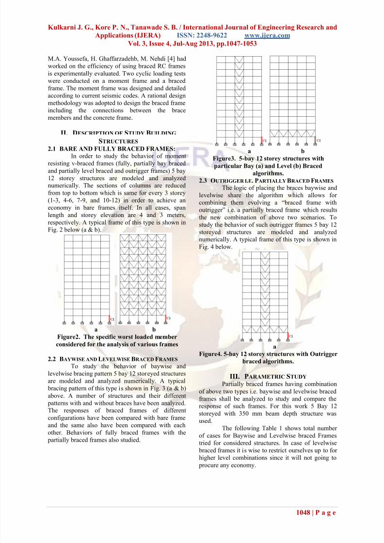
2.3 OUTRIGGER I.E. PARTIALLY BRACED FRAMES
The logic of placing the braces baywise andlevelwise share the algorithm which allows for
combining them evolving a “braced frame with
outrigger” i.e. a partially braced frame which results
the new combination of above two scenarios. To
study the behavior of such outrigger frames 5 bay 12
storeyed structures are modeled and analyzednumerically. A typical frame of this type is shown in
Fig. 4 below.
a
Figure4. 5-bay 12 storey structures with Outrigger
braced algorithms.
III. PARAMETRIC STUDY Partially braced frames having combination
of above two types i.e. baywise and levelwise braced
frames shall be analyzed to study and compare theresponse of such frames. For this work 5 Bay 12
storeyed with 350 mm beam depth structure was
used.
The following Table 1 shows total number
of cases for Baywise and Levelwise braced Frames
tried for considered structures. In case of levelwise
braced frames it is wise to restrict ourselves up to for
higher level combinations since it will not going to
procure any economy.

7/28/2019 f q 3410471053
http://slidepdf.com/reader/full/f-q-3410471053 3/7
Kulkarni J. G., Kore P. N., Tanawade S. B. / International Journal of Engineering Research and
Applications (IJERA) ISSN: 2248-9622 www.ijera.com
Vol. 3, Issue 4, Jul-Aug 2013, pp.1047-1053
1049 | P a g e
Table1: No. of cases considered for Baywise &
Levelwise braced Frames for 12 storey structures.
No.
of Bays
Braced
No. of Bays Braced at a time
OneTw
o Three Four FiveTota
l
5-bay 5 10 10 5 -- 30
No.
of Leve
ls
Braced
No. of Levels Braced at a time
OneTw
oThree Four Five
Tota
l
5-bay 12 66 220 -- -- 298
Total No. of Cases Studied 328
3.1 CHECK DIGIT ALGORITHEMS:
Natural logarithm of reference number ‘N’as dimensionless parameter has been used as abscissawith respect to various considered parameters. The
reference number used here is pure number, which is
uniquely specified for the frame and bracing pattern
tried. The check digit special algorithms are used for
alpha and/or alphanumeric character fields. Each
character is assigned a numeric equivalent. The
numeric equivalents are weighted and the products
are summed. The total is divided by the modulus to
determine the remainder. The remainder is compared
to a pre-assigned index to determine the check digit.
IV. INTERNAL FORCES Forces induced viz. axial force, shear force
and bending moment in one particular worst loaded
column segment is considered for this purpose asshown in Fig. 2 above. In order to facilitate the direct
comparison between bare and fully and/or partially
braced frames the latter have been analyzed for the
same geometry of mutually perpendicular/orthogonal
members for the same loading combination for which
the bare frame yielded the maximum design force in
the members so selected as shown in Fig. 2 (a, b & c)
above. However, once the design forces are evaluated
for fully and/or partially braced structures all
individual segments are redesigned and the minimumrequired cross sections and steel percentage was
calculated. Ultimately cost comparison is carried out
to compute economy.
V. OPTIMUM BAYWISE AND LEVELWISE
LOCATION FOR BRACING FRAMES 5.1 OPTIMUM BAYWISE LOCATION FOR BRACING
FRAMES 5 BAY 12 STOREY STRUCTURES
Fully braced frames described previously,
when analyzed, exhibit the values of forces and
displacements which are changing with the variation
of number of parameters. However, it was noticed
that the frames underwent a very small lateraldisplacement than was permissible. It is but obvious
that, when such frames are partially braced i.e. braced
all along the height in a particular or a combination
of number of bays which is less than total numbers of
bays for the frame, similarly when braced all along
the level or a combination of number of levels
concerned, will produce a larger displacementcompared to bare and fully braced frames but within
permissible limit i.e. 0.004H [9].
Hence it was decided to find out such
possibility of developing a particular pattern for partially braced frames, which would produce smaller
forces for worst load combinations. It goes without
saying that the bracing pattern tried always satisfied
strength as well as serviceability criterion.
Here dimensionless parameter (R a) i.e. ratio of axial
force which is the ratio of value of axial force in
member C1 for all cases of bays braced to axial force
in same member of bare frame as shown in Fig. 2 (a)
above. Same is applicable to ratio of shear force (R s)and to ratio bending moment (R m). The value of
internal forces in worst loaded column segment (C1)
of bare frame as shown in Fig. 2 (a) above is chosenas reference value for ratio R a, R s and R m.
It seen clearly that every graph shows two
lines parallel to the x-axis as shown in Fig. 5. If these
are considered as the upper and the lower limits as
may be appropriate to a particular dimensionless
parameter, one finds that many a times in case of partially braced frames the dimensionless parameters
observed exceeds the upper limits and/or is less than
the lower limit so considered. From which it
concludes that some of the braced frames may allowreduction in effect of considered parameters hence; it
would be advantageous to suggest certain working
range from specified/accepted minimum to maximum
for various internal forces concerned within which a
number of bracing patterns/cases produce the force
being considered for different cases. However, a
number of cases may be found common to all of them are the optimum cases as far as force levels are
concerned. The frames which appear between those
acceptable ranges were further taken into account for
the analysis and design purpose. Often symmetrical
cases are taken into account and tried in case of
baywise bracings only.All members of the frame are designed and
saving in material is found out. Amongst all the so
called best choices there is only one or more than one
choice/choices is made available which reduce the
total cost of structures compared to a bare frames,when all members are designed to carry the most
critical combination of the largest developed forces.
This bracing pattern/ these bracing patterns is/are the
optimum solution/solutions. It is found that such
bracing pattern is most economical than fully braced
one. Following Fig. 5 shows the variation of internalforces of 5 bay 12 storey structures and Fig. 6 shows
examples of optimum baywise braced frames for 5
7/28/2019 f q 3410471053
http://slidepdf.com/reader/full/f-q-3410471053 4/7
Kulkarni J. G., Kore P. N., Tanawade S. B. / International Journal of Engineering Research and
Applications (IJERA) ISSN: 2248-9622 www.ijera.com
Vol. 3, Issue 4, Jul-Aug 2013, pp.1047-1053
1050 | P a g e
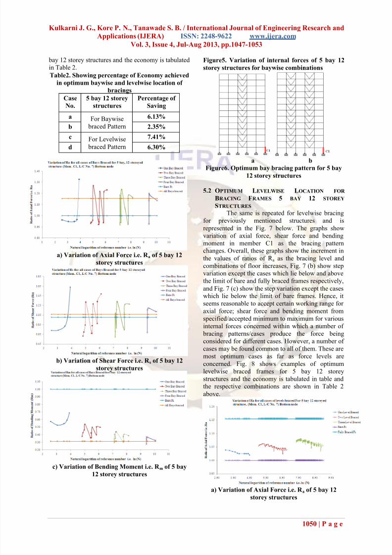
bay 12 storey structures and the economy is tabulated
in Table 2.
Table2. Showing percentage of Economy achieved
in optimum baywise and levelwise location of
bracings
CaseNo.
5 bay 12 storeystructures
Percentage of Saving
a For Baywise
braced Pattern
6.13%
b 2.35%
c For Levelwise
braced Pattern
7.41%
d 6.30%
a) Variation of Axial Force i.e. R a of 5 bay 12
storey structures
b) Variation of Shear Force i.e. R s of 5 bay 12
storey structures
c) Variation of Bending Moment i.e. R m of 5 bay
12 storey structures
Figure5. Variation of internal forces of 5 bay 12
storey structures for baywise combinations
a b
Figure6. Optimum bay bracing pattern for 5 bay
12 storey structures
5.2 OPTIMUM LEVELWISE LOCATION FOR
BRACING FRAMES 5 BAY 12 STOREY
STRUCTURES The same is repeated for levelwise bracing
for previously mentioned structures and is
represented in the Fig. 7 below. The graphs show
variation of axial force, shear force and bending
moment in member C1 as the bracing patternchanges. Overall, these graphs show the increment in
the values of ratios of R a as the bracing level and
combinations of floor increases, Fig. 7 (b) show step
variation except the cases which lie below and above
the limit of bare and fully braced frames respectively,
and Fig. 7 (c) show the step variation except the caseswhich lie below the limit of bare frames. Hence, it
seems reasonable to accept certain working range for
axial force; shear force and bending moment from
specified/accepted minimum to maximum for various
internal forces concerned within which a number of
bracing patterns/cases produce the force being
considered for different cases. However, a number of
cases may be found common to all of them. These are
most optimum cases as far as force levels are
concerned. Fig. 8 shows examples of optimum
levelwise braced frames for 5 bay 12 storey
structures and the economy is tabulated in table and
the respective combinations are shown in Table 2above.
a) Variation of Axial Force i.e. R a of 5 bay 12
storey structures
7/28/2019 f q 3410471053
http://slidepdf.com/reader/full/f-q-3410471053 5/7
Kulkarni J. G., Kore P. N., Tanawade S. B. / International Journal of Engineering Research and
Applications (IJERA) ISSN: 2248-9622 www.ijera.com
Vol. 3, Issue 4, Jul-Aug 2013, pp.1047-1053
1051 | P a g e
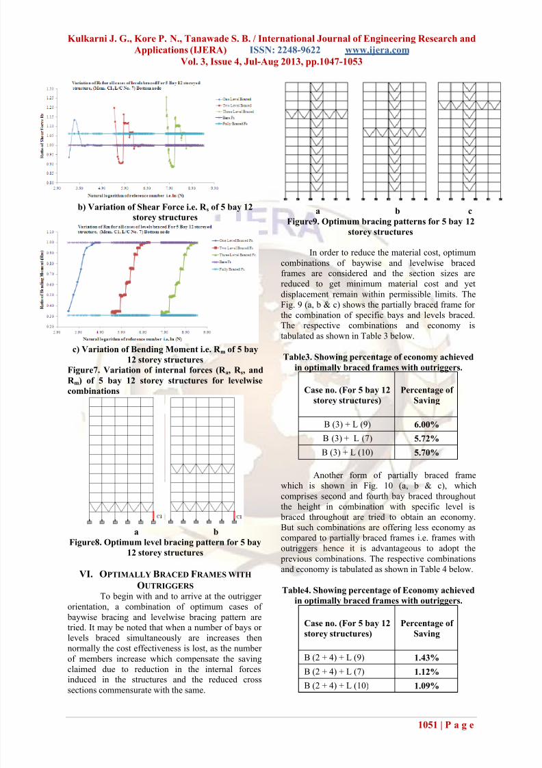
b) Variation of Shear Force i.e. R s of 5 bay 12
storey structures
c) Variation of Bending Moment i.e. R m of 5 bay
12 storey structures
Figure7. Variation of internal forces (R a, R s, and
R m) of 5 bay 12 storey structures for levelwise
combinations
a b
Figure8. Optimum level bracing pattern for 5 bay
12 storey structures
VI. OPTIMALLY BRACED FRAMES WITH
OUTRIGGERS To begin with and to arrive at the outrigger
orientation, a combination of optimum cases of
baywise bracing and levelwise bracing pattern aretried. It may be noted that when a number of bays or
levels braced simultaneously are increases then
normally the cost effectiveness is lost, as the number
of members increase which compensate the saving
claimed due to reduction in the internal forcesinduced in the structures and the reduced cross
sections commensurate with the same.
a b c
Figure9. Optimum bracing patterns for 5 bay 12
storey structures
In order to reduce the material cost, optimum
combinations of baywise and levelwise bracedframes are considered and the section sizes are
reduced to get minimum material cost and yet
displacement remain within permissible limits. The
Fig. 9 (a, b & c) shows the partially braced frame for
the combination of specific bays and levels braced.The respective combinations and economy is
tabulated as shown in Table 3 below.
Table3. Showing percentage of economy achieved
in optimally braced frames with outriggers.
Case no. (For 5 bay 12
storey structures)
Percentage of
Saving
B (3) + L (9) 6.00%
B (3) + L (7) 5.72%
B (3) + L (10) 5.70%
Another form of partially braced frame
which is shown in Fig. 10 (a, b & c), which
comprises second and fourth bay braced throughout
the height in combination with specific level is
braced throughout are tried to obtain an economy.
But such combinations are offering less economy as
compared to partially braced frames i.e. frames withoutriggers hence it is advantageous to adopt the
previous combinations. The respective combinations
and economy is tabulated as shown in Table 4 below.
Table4. Showing percentage of Economy achieved
in optimally braced frames with outriggers.
Case no. (For 5 bay 12
storey structures)
Percentage of
Saving
B (2 + 4) + L (9) 1.43%
B (2 + 4) + L (7) 1.12%B (2 + 4) + L (10) 1.09%

7/28/2019 f q 3410471053
http://slidepdf.com/reader/full/f-q-3410471053 6/7
Kulkarni J. G., Kore P. N., Tanawade S. B. / International Journal of Engineering Research and
Applications (IJERA) ISSN: 2248-9622 www.ijera.com
Vol. 3, Issue 4, Jul-Aug 2013, pp.1047-1053
1052 | P a g e
a b c
Figure10. Optimum bracing patterns for 5 bay 12
storey structures
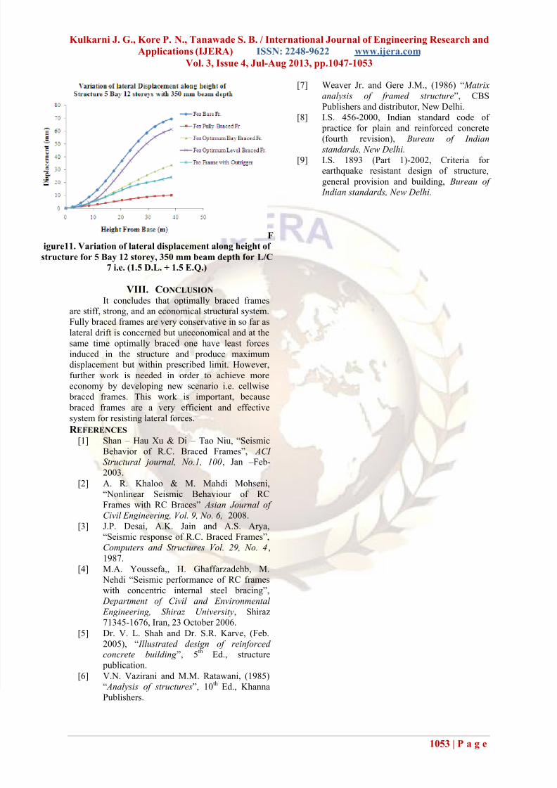
VII. STOREY DRIFT
The lateral displacements of frames wereobserved at common point at specific position in 5 bay 12
storey structures. The comparison is made between bare,
fully braced, partially braced i.e. optimum bay braced and
level braced and outrigger. It was checked whether the
structure satisfies maximum permissible relative lateral
drift criterion as per IS: 1893-2002 (Part-I) which is
0.004H [9]. To insure the serviceability criterion,
considering the lowest point as base of structure and
highest point as top of the structure maximum
relative drift is found and simultaneously compared
with the permissible one as well as with other analyzed structures such as fully braced, partially
braced and outriggers. The values are tabulated in
Table 5 and the variation is shown in Fig. 11 below.
For bare frames the lateral drift is well within the permissible one, but it is increasing as one move
towards the top most point of structure. Also the
lateral displacements for fully braced frames are
getting substantially reduced as compared with bare
frame, but these are uneconomical structures from
saving point of view. For optimally bay braced
frames and for outriggers the lateral displacements
are getting reduced by near about half and more as
compared to the bare frames. There is no valuablereduction in the lateral displacement for optimally
levelwise braced frames.
Table5. Showing variation of lateral displacement along height of structure for 5 Bay 12 storey structure
with 350 mm beam depth
Analyzed Structures of 5 Bay 12 storey structures
for 350 mm beam Depth
Ht. From
Base (m)
Bare
Frame
(mm)
Fully Braced
Frame (mm)
Optimum Bay
Braced (mm)
Optimum Level
Braced (mm)
Frame with
Outrigger (mm)
0 0 0 0 0 0
2.44 1.05 0.66 0.74 0.59 0.742
5.44 4.14 1.48 2.27 1.68 2.208
8.44 8.72 2.26 4.31 4.17 4.104
11.44 14.23 3.00 6.62 8.04 6.228
14.44 21.12 4.13 9.44 13.88 8.767
17.44 28.95 5.18 12.55 21.2 11.456
20.44 36.98 6.13 15.78 28.97 14.141
23.44 45.00 7.14 19.13 36.88 16.706
26.44 52.32 8.01 22.44 44.15 18.584
29.44 58.58 8.74 25.61 50.4 19.837
32.44 63.56 9.33 28.56 55.38 21.164
35.44 67.1 9.77 31.21 58.92 22.669
38.44 69.57 10.13 33.63 61.40 24.111
7/28/2019 f q 3410471053
http://slidepdf.com/reader/full/f-q-3410471053 7/7
Kulkarni J. G., Kore P. N., Tanawade S. B. / International Journal of Engineering Research and
Applications (IJERA) ISSN: 2248-9622 www.ijera.com
Vol. 3, Issue 4, Jul-Aug 2013, pp.1047-1053
1053 | P a g e
F
igure11. Variation of lateral displacement along height of
structure for 5 Bay 12 storey, 350 mm beam depth for L/C
7 i.e. (1.5 D.L. + 1.5 E.Q.)
VIII. CONCLUSION It concludes that optimally braced frames
are stiff, strong, and an economical structural system.
Fully braced frames are very conservative in so far as
lateral drift is concerned but uneconomical and at the
same time optimally braced one have least forces
induced in the structure and produce maximumdisplacement but within prescribed limit. However,
further work is needed in order to achieve more
economy by developing new scenario i.e. cellwise
braced frames. This work is important, because
braced frames are a very efficient and effective
system for resisting lateral forces.
R EFERENCES [1] Shan – Hau Xu & Di – Tao Niu, “Seismic
Behavior of R.C. Braced Frames”, ACI Structural journal, No.1, 100, Jan – Feb-
2003.
[2] A. R. Khaloo & M. Mahdi Mohseni,
“Nonlinear Seismic Behaviour of RC
Frames with RC Braces” Asian Journal of
Civil Engineering, Vol. 9, No. 6, 2008.
[3] J.P. Desai, A.K. Jain and A.S. Arya,
“Seismic response of R.C. Braced Frames”,
Computers and Structures Vol. 29, No. 4 ,
1987.
[4] M.A. Youssefa,, H. Ghaffarzadehb, M.
Nehdi “Seismic performance of RC frames
with concentric internal steel bracing”,
Department of Civil and Environmental
Engineering, Shiraz University, Shiraz
71345-1676, Iran, 23 October 2006.
[5] Dr. V. L. Shah and Dr. S.R. Karve, (Feb.
2005), “ Illustrated design of reinforced concrete building ”, 5
thEd., structure
publication.
[6] V.N. Vazirani and M.M. Ratawani, (1985)
“ Analysis of structures”, 10
th
Ed., KhannaPublishers.
[7] Weaver Jr. and Gere J.M., (1986) “ Matrix
analysis of framed structure”, CBS
Publishers and distributor, New Delhi.
[8] I.S. 456-2000, Indian standard code of
practice for plain and reinforced concrete
(fourth revision), Bureau of Indian standards, New Delhi.
[9] I.S. 1893 (Part 1)-2002, Criteria for
earthquake resistant design of structure,
general provision and building, Bureau of Indian standards, New Delhi.