EZ2F Install Guide - Zoned Air Conditioning, Dampers, and ...
23
InstallaƟon Guide EZ2F EZ2F SmartZone™ Zone Controller InstallaƟon and Start‐up Guide The ORIGINAL SmartZone™
Transcript of EZ2F Install Guide - Zoned Air Conditioning, Dampers, and ...

Installa on Guide EZ2F
EZ2F SmartZone™
Zone Controller Installa on and Start‐up Guide
The ORIGINAL SmartZone™

Installa on Guide EZ2F
Input Ra ngs:
Voltage: 18‐40 VAC 50/60 HZ transformer of 40 VA or more
Current Draw:
Zone Controller: 10 VA
PO/PC Dampers: 3 VA
PC/SR Dampers: 8VA
PO/SR Dampers: 8 VA
All VA specifica ons at 24 VAC
Fuse:
5 x 20mm 30 ma Slo‐Blo
Temperature Ra ngs:
Shipping: ‐20° to 150° F
Opera ng: ‐20° to 165° F
Humidity Ra ngs:
5% to 95% RH non‐condensing
Wiring:
18‐gauge SOLID wire
CONFIGURATION OPTIONS
Op on #01 Set board func on ‐ Master or Slave
Op on #02 Set slave address
Op on #03 Set system type
Op on #04 NOT USED/FOR FUTURE USE
Op on #05 Set equipment stage (two‐stage system ONLY)
Op on #06 Set thermostat type (heat pump system ONLY)
Op on #07 Set reversing valve actua on
Op on #08 NOT USED/FOR FUTURE USE
Op on #09 Set gas high temp cutout (gas and electric furnace ONLY)
Op on #10 Set low temp cutout
Op on #11 Set heat pump high temp cutout (heat pump system ONLY)
Op on #12 Set aux. heat cut‐in temp (single‐stage heat pump ONLY)
Op on #13 Set aux. heat cut‐in me (single‐stage heat pump ONLY)
Op on #14 Set economizer mode ‐ on or off
Op on #15 Set economizer temperature setpoint (ONLY if economizer turned ON)
Op on #16 Set fresh air minutes per hour (ONLY if economizer turned OFF)
Op on #17 Set fresh air sensor mode ‐ on or off (ONLY if fresh air minutes are greater than ZERO)
Op on #18 Set fresh air low‐temp lockout (ONLY if fresh air sensor mode is ON)
Op on #19 Set fresh air high‐temp lockout (ONLY if fresh air sensor mode is ON)
Op on #20 Set dual fuel heat pump outdoor low‐temp lockout (dual fuel system ONLY)
Op on #21 Set second stage lockout ‐ on or off (two‐stage equipment ONLY)
Op on #22 Set zone 1 priority
Op on #23 Set auto changeover me ‐ 10 or 15 minutes
Op on #24 Disable aux. heat staging above 40 degrees outside air (heat pump systems ONLY)
Op on #25 Allow zone 1 thermostat staging (two‐stage systems ONLY)
Copyright © 2013 XCI Zoning Page 1 Rev 1.0 2013‐7‐23

Installa on Guide EZ2F
MOUNTING
Mount the SmartZone controller near the HVAC equipment. It can be mounted on a wall, stud, roof tress or the supply
ductwork. It can be mounted in any orienta on, including flat on top of the supply plenum. When moun ng in a ver cal
posi on it should be leveled for a good appearance.
1. Remove the clear lid from the SmartZone enclosure.
2. Place the controller in the desired posi on and use the base as a template to mark the hole loca ons.
3. A ach the controller to the surface with the appropriate screws (not included). If a aching the controller to drywall
or ductboard, use hollow wall anchors to secure in place.
POWER
The SmartZone System requires a separate 24 VAC transformer (not included) for powering the SmartZone controller,
zone thermostats and dampers. It is recommended to install a fuse on the 24 VAC output from the transformer.
TRANSFORMER SIZING
The 24 volt transformer must be sized and fused based on the controller, the total dampers and the thermostats.
SmartZone Device Power
EZ2F Controller 10 VA
Power Open/Power Close Damper 3 VA
Spring Return Damper 10 VA
Typical Thermostat 2 VA
EXAMPLE: Transformer Calcula on:
1 SmartZone EZ2F (10 VA)
+ 2 POC Dampers (3 VA X 2)
+ 2 Thermostats (2 VA X 4)
= 20 VA Total
FUSE SIZING RULE OF THUMB
Transformer VA Fuse Size
40 2 amp
75 3 amp
100 4 amp
Connect the transformer to the 24V and 24C inputs on the zone control board.
CAUTION: Voltage Hazard. Can cause electrical shock or equipment damage. Disconnect power before beginning
installa on. Wire en re zone panel before applying transformer power.
Copyright © 2013 XCI Zoning Page 2 Rev 1.0 2013‐7‐23

Installa on Guide EZ2F
Wiring
Install thermostats using instruc ons provided with thermostats.
SmartZone is compa ble with most thermostats that have a common connec on or are ba ery operated. SmartZone will use
me and supply air temperature to automa cally manage staging. This eliminates the need for mul ‐stage thermostats.
On HEAT PUMP equipment ONLY, either Gas/Electric or Heat Pump thermostats can be used. It is recommended to use a Heat
Pump thermostat with an Emergency Heat switch on Zone 1 for all heat pump installa ons. An emergency heat call can ONLY
be ini ated from the ZONE 1 THERMOSTAT.
1. Connect either single stage gas/electric or heat pump thermostats to each terminal block labeled Zone 1 TSTAT and
Zone 2 TSTAT.
2. The Zone 1 TSTAT will operate Damper 1. The Zone 2 TSTAT will operate Damper 2.
3. Using 18 Gauge Solid Thermostat Wire, strip 1/2 inch of insula on from each wire. Hold down the orange bu on and
push the thermostat wire into the SCREWLESS terminals on the control board.
4. Connect the other end of the thermostat wire to the corresponding terminals on the thermostat.
5. To use the EC terminal on the Zone 1 TSTAT, a separate switch must be used to supply 24 VAC to this terminal. You
may also use a 2‐stage thermostat on Zone 1 ONLY if you want to control Zone 1 staging by connec ng Y2 from the
the thermostat to the EC terminal on the Zone 1 terminal block.
HEAT PUMP THERMOSTAT
GAS/ELECTRIC THERMOSTAT
Copyright © 2013 XCI Zoning Page 3 Rev 1.0 2013‐7‐23

Installa on Guide EZ2F
Wiring
SmartZone will operate either 2‐Wire Power Close/Spring Open dampers, or 3‐Wire Power Open/Power Close dampers.
Power Close/Spring Open 2‐Wire Dampers
1. Use 18/2 or 18/3 solid core wire.
2. Strip 1/2 inch of insula on from each wire.
3. Hold down the orange bu on on the Damper 1 terminal block labeled Z1‐PC and COM and push the two wires for the zone
damper into the SCREWLESS terminals.
4. Connect the other end of the wires to the SCREWLESS terminals on the zone damper.
5. Repeat steps 3 and 4 for the Zone 2 damper.
Power Open/Power Close 3‐Wire Dampers
1. Use 18/3 solid core wire
2. Strip 1/2 inch of insula on from each wire.
3. Hold down the orange bu on on the Damper 1 terminal block and push the three wires for the zone damper into the
SCREWLESS terminals. Use WHITE for Common (C), GREEN for Power Open (PO) and RED for Power Close (PC).
4. Connect the other end of the wires to the terminals on the zone damper, using the same color code.
5. Repeat steps 3 and 4 for the Zone 2 damper.
Copyright © 2013 XCI Zoning Page 4 Rev 1.0 2013‐7‐23

Installa on Guide EZ2F
PLUG IN SUPPLY AIR SENSOR HERE
PLUG IN FRESH AIR OR RETURN AIR
SENSOR HERE
PLUG IN SMARTLINK CABLE HERE IF USING AS AN EXPANSION BOARD
Wiring
Supply Air Temperature Sensor (SAS)
Sensor Placement (Loca on)
Gas/Electric ‐ Electric/Electric ‐ The SAS should be located in the
Supply Air Plenum where it will sense AVERAGE air temperature
within the Plenum. The ideal placement is 2 to 4 feet beyond
the evaporator coil. Make sure the sensor is in the air stream
and secured properly.
Heat Pump ‐ The SAS should be located inside the air handler
cabinet AFTER the evaporator coil but BEFORE the blower.
Make sure the sensor is in the air stream and properly secured.
Op onal Return Air Sensor (RAS)
Sensor Placement (Loca on)
The RAS should be located in the return air plenum before
the blower or evaporator coil sec on where it will sense the
AVERAGE return air temperature entering the air handler or
furnace. Make sure the sensor is in the air stream and
properly secured.
Fresh Air/Outdoor Air Sensor (OAS)
Sensor Placement (Loca on)
The OAS should be located under the eave of the structure
or under a ledge on the outdoor unit where it will not be in
direct sunlight. Secure the sensor in place and connect to
the controller with thermostat wire and the included plug‐in
connector.
SmartLink Cable
If using the EZ2F controller as a two‐zone expansion module,
plug one end of the cable into the 3‐pole receptacle at the
bo om of the controller, and plug the other end into the
3‐pole receptacle on the master controller. Up to nine (9)
expansion boards can be connected to the master controller.
(Maximum total of 40 zones)
Copyright © 2013 XCI Zoning Page 5 Rev 1.0 2013‐7‐23

Installa on Guide EZ2F
Wiring
A/C ‐ Gas Furnace and A/C ‐ Electric Furnace
Using 18 gauge solid thermostat wire, connect the Equipment Control Wires from the Indoor Unit to the EQUIPMENT terminal
block on the top right corner of the SmartZone Controller. Use the terminal labeled W1/EH for first stage heat. If using a two‐stage
furnace, connect W2/OB to W2 on the indoor equipment. Connect R from the equipment to RC on the SmartZone Controller.
Connect C from the equipment to C on the SmartZone Controller. THE C TERMINAL FROM THE EQUIPMENT MUST BE CONNECTED
TO THE CONTROLLER FROM THE EQUIPMENT FOR THE RC AND RH LED’S TO ILLUMINATE. POWER FROM THE EQUIPMENT
TRANSFORMER WILL ILLUMINATE THE RC AND RH TERMINAL LED’S, INDICATING THE EQUIPMENT TRANSFORMER IS CONNECTED.
NOTE: IF USING A TWO‐TRANSFORMER SYSTEM, WITH SEPARATE COOLING AND HEATING TRANSFORMERS, CONNECT THE R FROM
THE COOLING TRANSFORMER TO RC ON THE CONTROLLER. CONNECT THE R FROM THE HEATING TRANSFORMER TO RH ON THE
CONTROLLERS. REMOVE THE BLACK JUMPER LOCATED JUST BELOW THE RC/RH LED’S TO SEPARATE THE POWER INPUTS.
JUMPER
GAS/ELECTRIC
Or
ELECTRIC/ELECTRIC
Electric Heat Pump
Using 18 gauge solid thermostat wire, connect the Equipment Control Wires from the Indoor Unit to the EQUIPMENT terminal
Block on the top right corner of the SmartZone Controller. Use the terminal labeled W1/EH for the auxiliary heat strips.
Connect the W2/OB terminal to the O/B terminal on the equipment (REVERSING VALVE). Connect R from the equipment to RC
on the SmartZone Controller. Connect C from the equipment to C on the SmartZone Controller. THE C TERMINAL FROM THE
EQUIPMENT MUST BE CONNECTED TO THE CONTROLLER FROM THE EQUIPMENT FOR THE RC AND RH LED’S TO ILLUMINATE.
POWER FROM THE EQUIPMENT TRANSFORMER WILL ILLUMINATE THE RC AND RH TERMINAL LED’S, INDICATING THE EQUIPMENT
TRANSFORMER IS CONNECTED AND WORKING.
NOTE: The jumper for RH/RC should NOT be removed on a heat pump system.
HEAT PUMP
EQUPMENT
1 OR 2 STAGE
Copyright © 2013 XCI Zoning Page 6 Rev 1.0 2013‐7‐23

Installa on Guide EZ2F
Configura on and Setup
The EZ2F SmartZone Controller has a state of the art microprocessor for reliable control of the equipment and zone dampers.
The simple step by step setup eliminates the need for confusing dip switches. The full status back‐lit LCD display guides you thru
each step of the setup process. Depending on the type of equipment selected, the display will show you each available op on for
the system type selected.
A/C ‐ GAS HEAT AND A/C ‐ ELECTRIC HEAT
Make sure that all wiring for the thermostats, zone dampers and equipment is complete. The RH and RC led’s should be illuminat‐
ed. The GREEN connector from the Supply Air Sensor (SAS) should be plugged firmly into the receptacle marked SA SNS on the
controller. If using a Return Air Sensor (RAS) or Fresh Air Sensor (OAS) the GREEN connector should be firmly plugged into the
receptacle marked FA SNS on the controller. If using the controller as an expansion module, the GREEN 3‐pole connector should
be firmly plugged into the receptacle marked SMART LINK at the bo om of the controller. Apply power from the 24VAC trans‐
former connected to the PWR connector on the controller. The controller will power up and display a splash screen on the LCD
display. The red R led’s for both thermostats and the green led’s for both dampers will illuminate. The display will then show the
factory default se ngs for the controller.
Press the SETUP bu on to enter the configura on mode. The screen will display the SETUP MENU and OPTION #01 ‐ SET BOARD
FUNCTION. The factory default is MASTER. If using the controller as an expansion module, press the UP or DOWN bu on to
change to SLAVE. Press the SETUP bu on to proceed to the next op on. (NOTE: If using the controller as an expansion module,
the next selec on will be OPTION #02 ‐ SET SLAVE ADDRESS. Each expansion board will have its own address, numbered 1 thru 9.
The default address is 1. If using more than one expansion board, the second expansion board will be address 2 and so on, up to 9
expansion boards. ) Press the SETUP bu on to proceed to the next op on.
IF YOU GO PAST THE DESIRED SETUP OPTION, PRESS THE RESET BUTTON TO START OVER.
OPTION #03 ‐ SET SYSTEM TYPE The default se ng is A/C ‐ GAS HEAT. Use the up bu on to select A/C ‐ ELEC HEAT. Press the
SETUP bu on to proceed to the next op on.
OPTION #05 ‐ SET EQUIPMENT STAGE The default se ng is 1‐STAGE. Press the UP or DOWN bu on to change to 2‐STAGE.
Press the SETUP bu on to proceed to the next op on.
OPTION #09 ‐ SET HI‐TEMP CUT‐OUT The default setting is 135 F. Press the UP or DOWN button to change the temperature. The
adjustable range is 125 F to 150 F. Press the SETUP button to proceed to the next option.
NOTE: When using electric furnace, the HI‐TEMP CUT‐OUT should be set no higher than 125° F.
Copyright © 2013 XCI Zoning Page 7 Rev 1.0 2013‐7‐23

Installa on Guide EZ2F
Copyright © 2013 XCI Zoning Page 8 Rev 1.0 2013‐7‐23
Configura on and Setup OPTION #10 ‐ SET LO‐TEMP CUTOUT The default se ng is 48° F. Press the UP or DOWN bu on to change the temperature.
The adjustable range is 42° F to 52° F. Press the SETUP bu on to proceed to the next op on.
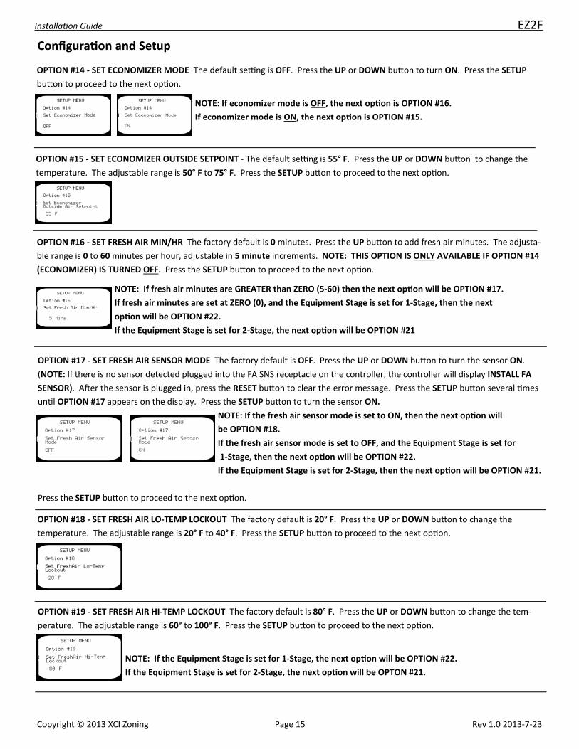
OPTION #14 ‐ SET ECONOMIZER MODE The default se ng is OFF. Press the UP or DOWN bu on to turn ON. Press the SETUP
bu on to proceed to the next op on.
NOTE: If economizer mode is OFF, the next op on is OPTION #16.
If economizer mode is ON, the next op on is OPTION #15.
OPTION #15 ‐ SET ECONOMIZER OUTSIDE SETPOINT ‐ The default se ng is 55° F. Press the UP or DOWN bu on to change the
temperature. The adjustable range is 50° F to 75° F. Press the SETUP bu on to proceed to the next op on.
OPTION #16 ‐ SET FRESH AIR MIN/HR The factory default is 0 minutes. Press the UP bu on to add fresh air minutes. The adjusta‐
ble range is 0 to 60 minutes per hour, adjustable in 5 minute increments. NOTE: THIS OPTION IS ONLY AVAILABLE IF OPTION #14
(ECONOMIZER) IS TURNED OFF. Press the SETUP bu on to proceed to the next op on.
NOTE: If fresh air minutes are GREATER than ZERO (0) then the next op on will be OPTION #17.
If fresh air minutes are set at ZERO (0), and the Equipment Stage is set for 1‐Stage, then the next op on
will be OPTION #22.
If the Equipment Stage is set for 2‐Stage, the next op on will be OPTION #21
OPTION #17 ‐ SET FRESH AIR SENSOR MODE The factory default is OFF. Press the UP or DOWN bu on to turn the sensor ON.
(NOTE: If there is no sensor detected plugged into the FA SNS receptacle on the controller, the controller will display INSTALL FA
SENSOR). A er the sensor is plugged in, press the RESET bu on to clear the error message. Press the SETUP bu on several mes
un l OPTION #17 appears on the display. Press the SETUP bu on to turn the sensor ON. Press the setup bu on to proceed to the
next op on.
NOTE: If the fresh air sensor mode is set to ON, then the next op on will be OPTION #18.
If the fresh air sensor mode is set to OFF, and the Equipment Stage is set for 1‐Stage, then the next op on will be OPTION #22. If
the Equipment Stage is set for 2‐Stage, then the next op on will be OPTION #21.

Installa on Guide EZ2F
Copyright © 2013 XCI Zoning Page 9 Rev 1.0 2013‐7‐23
Configura on and Setup
OPTION #18 ‐ SET FRESH AIR LO‐TEMP LOCKOUT The factory default is 20° F. Press the UP or DOWN bu on to change the tem‐
perature. The adjustable range is 20° F to 40° F. Press the SETUP bu on to proceed to the next op on.
OPTION #19 ‐ SET FRESH AIR HI‐TEMP LOCKOUT The factory default is 80° F. Press the UP or DOWN bu on to change the tem‐
perature. The adjustable range is 60° to 100° F. Press the SETUP bu on to proceed to the next op on.
NOTE: If the Equipment Stage is set for 1‐Stage, the next op on will be OPTION #22.
If the Equipment Stage is set for 2‐Stage, the next op on will be OPTON #21.
OPTION #21 ‐ SET SECOND STAGE LOCKOUT The factory default is OFF. Press the UP or DOWN bu on to turn ON. When this
op on is turned ON, the controller WILL NOT ENERGIZE 2ND STAGE if only ONE ZONE is calling. Press the SETUP bu on to
proceed to the next op on.
OPTION #22 ‐ SET ZONE 1 PRIORITY The factory default is OFF. Press the UP or DOWN bu on to turn ON. When this op on is
turned on, any call from the ZONE 1 THERMOSTAT will override any call from the ZONE 2, 3 or 4 THERMOSTAT. If a call exists on
any thermostat other than the ZONE 1 THERMOSTAT, and an opposing call is made from the ZONE 1 THERMOSTAT, the system will
immediately to into a 3‐minute PURGE and then will turn on the equipment based on the call from the ZONE 1 THERMOSTAT.
Press the SETUP bu on to proceed to the next op on.
OPTION #23 ‐ SET AUTO CHANGEOVER TIME The factory default is 10 minutes. Press the up or down bu on to change the se ng
to 15 MINUTES. This se ng determines the amount of me that elapses a er an opposing call occurs and the system changes over
to the opposing call. Press the SETUP bu on to proceed.
NOTE: If the equipment stage is set for 1‐STAGE, pressing the SETUP bu on
will exit the configura on mode.
If the equipment stage is set for 2‐STAGE then the setup will proceed to
OPTION #25.

Installa on Guide EZ2F
Copyright © 2013 XCI Zoning Page 10 Rev 1.0 2013‐7‐23
Configura on and Setup
OPTION #25 ‐ ALLOW ZONE 1 THERMOSTAT STAGING The default se ng is OFF. Press the UP or DOWN bu on to turn ON.
When this se ng is ON, the controller will accept a 2nd stage call from the Zone 1 Thermostat. NOTE: When this op on is
turned ON, Zone 1 will DISREGARD 2ND STAGE LOCKOUT if Op on #21 is turned ON.
NOTE: This op on will only be available if Op on #05 is set for 2‐STAGE.
Press the SETUP bu on to exit the configura on mode.
ELECTRIC HEAT PUMP ‐ ELECTRIC AUXILLIARY HEAT
Press the SETUP bu on to enter the configura on mode. The screen will display the SETUP MENU AND OPTION #03 ‐ SET SYSTEM
TYPE. The default se ng is A/C ‐ GAS ELECTRIC. Press the UP bu on twice to change the system to ELECTRIC HEAT PUMP. Press
the SETUP bu on to proceed to the next op on.
SYSTEM IDLE SCREEN
OPTION #05 ‐ SET EQUIPMENT STAGE The default se ng is 1‐STAGE. If using single stage equipment, press the SETUP bu on to
proceed to the next op on. If using 2‐stage equipment, press the UP or DOWN bu on to select 2‐STAGE. Press the SETUP bu on
to proceed to the next op on.
OPTION #06 ‐ SET THERMOSTAT 1 TYPE The default se ng is GAS/ELECTRIC. Press the UP or DOWN bu on to change to HEAT
PUMP. Press the SETUP bu on to SET THERMOSTAT 2 TYPE. The default se ng is GAS/ELECTRIC. Press the UP or DOWN bu on
to change to HEAT PUMP. Press the SETUP bu on to proceed to the next op on.
NOTE: A heat pump thermostat with an emergency heat switch MUST be installed on Zone 1 to manually turn on auxiliary heat.
OPTION #07 ‐ SET REVERSING VALVE ACTUATION The default se ng is REV‐O. Press the UP or DOWN bu on to change to REV‐B.
NOTE: When set as REV‐O, the reversing valve will energize in COOLING. When set as REV‐B, the reversing valve will energize in
HEATING. Press the SETUP bu on to proceed to the next op on.

Installa on Guide EZ2F
Configura on and Setup
OPTION #10 ‐ SET LO‐TEMP CUTOUT The default se ng is 48 F. Press the UP or DOWN bu on to change the temperature. The
adjustable range is 42 F to 52 F. Press the SETUP bu on to proceed to the next op on.
OPTION #11 ‐ SET HEAT PUMP HI‐TEMP CUTOUT The default se ng is 120 F. Press the UP or DOWN bu on to change the
se ng. The adjustable range is 110 F ‐ 125 F. Press the SETUP bu on to proceed to the next op on.
NOTE: If Op on #05 is set for 1‐STAGE, the next op on will be OPTION #12.
If Op on #05 is set for 2‐STAGE, the next op on will be OPTION #14.
OPTION #12 ‐ SET AUX HEAT CUT‐IN TEMP The default is 90 F. Press the UP or DOWN bu on to change the se ng. The
adjustable range is 90 ‐ 100 F. Press the SETUP bu on to proceed to the next op on.
NOTE: This op on only available on 1‐STAGE systems.
OPTION #13 ‐ SET AUX HEAT CUTIN TIME The default is 6 Mins. Press the UP or DOWN bu on to change the se ng. The adjusta‐
ble range is 3 ‐ 6 Mins. Press the SETUP bu on to proceed to the next step.
NOTE: This op on only available on 1‐STAGE systems.
OPTION #14 ‐ SET ECONOMIZER MODE The default se ng is OFF. Press the UP or DOWN bu on to turn ON. Press the SETUP
bu on to proceed to the next op on.
NOTE: If economizer mode is OFF, the next op on is OPTION #16.
If economizer mode is ON, the next op on is OPTION #15.
OPTION #15 ‐ SET ECONOMIZER OUTSIDE SETPOINT ‐ The default se ng is 55° F. Press the UP or DOWN bu on to change the
temperature. The adjustable range is 50° F to 75° F. Press the SETUP bu on to proceed to the next op on.
OPTION #16 ‐ SET FRESH AIR MIN/HR The factory default is 0 minutes. Press the UP bu on to add fresh air minutes. The adjusta‐
ble range is 0 to 60 minutes per hour, adjustable in 5 minute increments. NOTE: THIS OPTION IS ONLY AVAILABLE IF OPTION #14
(ECONOMIZER) IS TURNED OFF. Press the SETUP bu on to proceed to the next op on.
NOTE: If fresh air minutes are GREATER than ZERO (0) then the next op on will be OPTION #17.
If fresh air minutes are set at ZERO (0), and the Equipment Stage is set for 1‐Stage, then the next op on will
be OPTION #22.
If the Equipment Stage is set for 2‐Stage, the next op on will be OPTION #21
Copyright © 2013 XCI Zoning Page 11 Rev 1.0 2013‐7‐23

Installa on Guide EZ2F
OPTION #17 ‐ SET FRESH AIR SENSOR MODE The factory default is OFF. Press the UP or DOWN bu on to turn the sensor ON.
(NOTE: If there is no sensor detected plugged into the FA SNS receptacle on the controller, the controller will display INSTALL FA
SENSOR). A er the sensor is plugged in, press the RESET bu on to clear the error message. Press the SETUP bu on several mes
un l OPTION #17 appears on the display. Press the SETUP bu on to turn the sensor ON. Press the setup bu on to proceed to the
next op on.
NOTE: If the fresh air sensor mode is set to ON, then the next op on will be OPTION #18.
If the fresh air sensor mode is set to OFF, and the Equipment Stage is set for 1‐Stage, then the next op on will be OPTION #22. If
the Equipment Stage is set for 2‐Stage, then the next op on will be OPTION #21.
Configura on and Setup
OPTION #18 ‐ SET FRESH AIR LO‐TEMP LOCKOUT The factory default is 20° F. Press the UP or DOWN bu on to change the
temperature. The adjustable range is 20° F to 40° F. Press the SETUP bu on to proceed to the next op on.
OPTION #19 ‐ SET FRESH AIR HI‐TEMP LOCKOUT The factory default is 80° F. Press the UP or DOWN bu on to change the tem‐
perature. The adjustable range is 60° to 100° F. Press the SETUP bu on to proceed to the next op on.
NOTE: If the Equipment Stage is set for 1‐Stage, the next op on will be OPTION #22.
If the Equipment Stage is set for 2‐Stage, the next op on will be OPTON #21.
OPTION #21 ‐ SET SECOND STAGE LOCKOUT The factory default is OFF. Press the UP or DOWN bu on to turn ON. When this
op on is turned ON, the controller WILL NOT ENERGIZE 2ND STAGE if only ONE ZONE is calling. Press the SETUP bu on to
proceed to the next op on.
NOTE: This op on will only appear if Op on #05 is set for 2‐STAGE equipment.
OPTION #22 ‐ SET ZONE 1 PRIORITY The factory default is OFF. Press the UP or DOWN bu on to turn ON. When this op on is
turned on, any call from the ZONE 1 THERMOSTAT will override any call from the ZONE 2, 3 or 4 THERMOSTAT. If a call exists on
any thermostat other than the ZONE 1 THERMOSTAT, and an opposing call is made from the ZONE 1 THERMOSTAT, the system will
immediately to into a 3‐minute PURGE and then will turn on the equipment based on the call from the ZONE 1 THERMOSTAT.
Press the SETUP bu on to proceed to the next op on.
Copyright © 2013 XCI Zoning Page 12 Rev 1.0 2013‐7‐23

Installa on Guide EZ2F
Configura on and Setup
OPTION #23 ‐ SET AUTO CHANGEOVER TIME The factory default is 10 minutes. Press the up or down bu on to change the se ng
to 15 MINUTES. This se ng determines the amount of me that elapses a er an opposing call occurs and the system changes over
to the opposing call. Press the SETUP bu on to proceed.
OPTION #25 ‐ ALLOW ZONE 1 THERMOSTAT STAGING The default se ng is OFF. Press the UP or DOWN bu on to turn ON.
When this se ng is ON, the controller will accept a 2nd stage call from the Zone 1 Thermostat. NOTE: When this op on is turned
ON, Zone 1 will DISREGARD 2ND STAGE LOCKOUT if Op on #21 is turned ON.
NOTE: This op on will only be available if Op on #05 is set for 2‐STAGE.
Press the SETUP bu on to exit the configura on mode.
OPTION #24 ‐ DISABLE AUX HEAT STAGING ABOVE 40 DEG The default se ng is OFF. Press the UP or DOWN bu on to turn ON.
When this feature is turned ON, the controller WILL NOT stage on Auxiliary Heat if the OUTDOOR TEMPERATURE is above 40° F.
NOTE: This op on REQUIRES the use of a FRESH AIR SENSOR connected to the
controller.
DUAL FUEL HEAT PUMP
Press the SETUP bu on TWO TIMES to enter the configura on mode. The screen will display the SETUP MENU AND OPTION #03 ‐
SET SYSTEM TYPE. The default se ng is A/C ‐ GAS ELECTRIC. Press the UP bu on three mes to change the system to DUAL FUEL
HEAT PUMP. NOTE: The outdoor FRESH AIR SENSOR MUST be plugged into the controller to configure for DUAL FUEL HEAT
PUMP. If the sensor is NOT plugged in, the screen will display INST FA SNSR FOR DFHP. A er installing the FRESH AIR SENSOR,
press the RESET bu on to re‐enter the configura on mode.
Press the SETUP bu on to proceed to the next op on.
Copyright © 2013 XCI Zoning Page 13 Rev 1.0 2013‐7‐23
OPTION #05 ‐ SET EQUIPMENT STAGE The default se ng is 1‐STAGE. Press the UP or DOWN bu on to change to 2‐STAGE.
Press the SETUP bu on to proceed to the next op on.

Installa on Guide EZ2F
Configura on and Setup
OPTION #06 ‐ SET THERMOSTAT 1 TYPE The default se ng is GAS/ELECTRIC. Press the UP or DOWN bu on to change to HEAT
PUMP. Press the SETUP bu on to SET THERMOSTAT 2 TYPE. The default se ng is GAS/ELECTRIC. Press the UP or DOWN bu on
to change to HEAT PUMP. Press the SETUP bu on to proceed to the next op on.
NOTE: A heat pump thermostat with an emergency heat switch MUST be installed on Zone 1 to manually turn on auxiliary heat.
OPTION #07 ‐ SET REVERSING VALVE ACTUATION The default se ng is REV‐O. Press the UP or DOWN bu on to change to REV‐B.
NOTE: When set as REV‐O, the reversing valve will energize in COOLING. When set as REV‐B, the reversing valve will energize in
HEATING. Press the SETUP bu on to proceed to the next op on.
OPTION #09 ‐ SET GAS HI‐TEMP CUT‐OUT The default setting is 135 F. Press the UP or DOWN button to change the temperature.
The adjustable range is 125 F to 150 F. Press the SETUP button to proceed to the next option.
OPTION #10 ‐ SET LO‐TEMP CUTOUT The default se ng is 48° F. Press the UP or DOWN bu on to change the temperature.
The adjustable range is 42° F to 52° F. Press the SETUP bu on to proceed to the next op on.
OPTION #11 ‐ SET HEAT PUMP HI‐TEMP CUTOUT The default se ng is 120 F. Press the UP or DOWN bu on to change the
se ng. The adjustable range is 110 F ‐ 125 F. Press the SETUP bu on to proceed to the next op on.
NOTE: If Op on #05 is set for 1‐STAGE, the next op on will be OPTION #12.
If Op on #05 is set for 2‐STAGE, the next op on will be OPTION #14.
OPTION #12 ‐ SET AUX HEAT CUT‐IN TEMP The default is 90 F. Press the UP or DOWN bu on to change the se ng. The
adjustable range is 90 ‐ 100 F. Press the SETUP bu on to proceed to the next op on.
NOTE: This op on only available on 1‐STAGE systems.
Copyright © 2013 XCI Zoning Page 14 Rev 1.0 2013‐7‐23
OPTION #13 ‐ SET AUX HEAT CUTIN TIME The default is 6 Mins. Press the UP or DOWN bu on to change the se ng. The adjusta‐
ble range is 3 ‐ 6 Mins. Press the SETUP bu on to proceed to the next step.
NOTE: This op on only available on 1‐STAGE systems.
Installa on Guide EZ2F
OPTION #14 ‐ SET ECONOMIZER MODE The default se ng is OFF. Press the UP or DOWN bu on to turn ON. Press the SETUP
bu on to proceed to the next op on.
NOTE: If economizer mode is OFF, the next op on is OPTION #16.
If economizer mode is ON, the next op on is OPTION #15.
Configura on and Setup
OPTION #15 ‐ SET ECONOMIZER OUTSIDE SETPOINT ‐ The default se ng is 55° F. Press the UP or DOWN bu on to change the
temperature. The adjustable range is 50° F to 75° F. Press the SETUP bu on to proceed to the next op on.
OPTION #16 ‐ SET FRESH AIR MIN/HR The factory default is 0 minutes. Press the UP bu on to add fresh air minutes. The adjusta‐
ble range is 0 to 60 minutes per hour, adjustable in 5 minute increments. NOTE: THIS OPTION IS ONLY AVAILABLE IF OPTION #14
(ECONOMIZER) IS TURNED OFF. Press the SETUP bu on to proceed to the next op on.
NOTE: If fresh air minutes are GREATER than ZERO (5‐60) then the next op on will be OPTION #17.
If fresh air minutes are set at ZERO (0), and the Equipment Stage is set for 1‐Stage, then the next
op on will be OPTION #22.
If the Equipment Stage is set for 2‐Stage, the next op on will be OPTION #21
OPTION #17 ‐ SET FRESH AIR SENSOR MODE The factory default is OFF. Press the UP or DOWN bu on to turn the sensor ON.
(NOTE: If there is no sensor detected plugged into the FA SNS receptacle on the controller, the controller will display INSTALL FA
SENSOR). A er the sensor is plugged in, press the RESET bu on to clear the error message. Press the SETUP bu on several mes
un l OPTION #17 appears on the display. Press the SETUP bu on to turn the sensor ON.
NOTE: If the fresh air sensor mode is set to ON, then the next op on will
be OPTION #18.
If the fresh air sensor mode is set to OFF, and the Equipment Stage is set for
1‐Stage, then the next op on will be OPTION #22.
If the Equipment Stage is set for 2‐Stage, then the next op on will be OPTION #21.
Press the SETUP bu on to proceed to the next op on.
OPTION #18 ‐ SET FRESH AIR LO‐TEMP LOCKOUT The factory default is 20° F. Press the UP or DOWN bu on to change the
temperature. The adjustable range is 20° F to 40° F. Press the SETUP bu on to proceed to the next op on.
OPTION #19 ‐ SET FRESH AIR HI‐TEMP LOCKOUT The factory default is 80° F. Press the UP or DOWN bu on to change the tem‐
perature. The adjustable range is 60° to 100° F. Press the SETUP bu on to proceed to the next op on.
NOTE: If the Equipment Stage is set for 1‐Stage, the next op on will be OPTION #22.
If the Equipment Stage is set for 2‐Stage, the next op on will be OPTON #21.
Copyright © 2013 XCI Zoning Page 15 Rev 1.0 2013‐7‐23

Installa on Guide EZ2F
Configura on and Setup
OPTION #20 ‐ SET DUAL FUEL HP OUTDOOR LO‐TEMP LOCKOUT The factory default is 30° F. Press the UP or DOWN bu on to
change. The adjustable range is 20° ‐ 45° F. Press the SETUP bu on to proceed to the next op on.
NOTE: The controller will display F/A and the outdoor temperature
OPTION #21 ‐ SET SECOND STAGE LOCKOUT The factory default is OFF. Press the UP or DOWN bu on to turn ON. When this
op on is turned ON, the controller WILL NOT ENERGIZE 2ND STAGE if only ONE ZONE is calling. Press the SETUP bu on to
proceed to the next op on.
NOTE: This op on will only appear if Op on #05 is set for 2‐STAGE equipment.
OPTION #22 ‐ SET ZONE 1 PRIORITY The factory default is OFF. Press the UP or DOWN bu on to turn ON. When this op on is
turned on, any call from the ZONE 1 THERMOSTAT will override any call from the ZONE 2 THERMOSTAT. If a call exists on the
ZONE 2 THERMOSTAT and an opposing call is made from the ZONE 1 THERMOSTAT, the system will immediately to into a 3‐minute
PURGE and then will turn on the equipment based on the call from the ZONE 1 THERMOSTAT. Press the SETUP bu on to proceed
to the next op on.
OPTION #23 ‐ SET AUTO CHANGEOVER TIME The factory default is 10 minutes. Press the up or down bu on to change the se ng
to 15 MINUTES. This se ng determines the amount of me that elapses a er an opposing call occurs and the system changes over
to the opposing call. Press the SETUP bu on to proceed.
OPTION #24 ‐ DISABLE AUX HEAT STAGING ABOVE 40 DEG The default se ng is OFF. Press the UP or DOWN bu on to turn ON.
When this feature is turned ON, the controller WILL NOT STAGE on Auxiliary Heat if the OUTDOOR TEMPERATURE is above 40° F.
Press the SETUP bu on to proceed to the next op on.
OPTION #25 ‐ ALLOW ZONE 1 THERMOSTAT STAGING The default se ng is OFF. Press the UP or DOWN bu on to turn ON.
When this se ng is ON, the controller will accept a 2nd stage call from the Zone 1 Thermostat. NOTE: When this op on is turned
ON, Zone 1 will DISREGARD 2ND STAGE LOCKOUT if Op on #21 is turned ON.
NOTE: This op on will only be available if Op on #05 is set for 2‐STAGE.
Press the SETUP bu on to exit the configura on mode.
Copyright © 2013 XCI Zoning Page 16 Rev 1.0 2013‐7‐23
Installa on Guide EZ2F
SEQUENCE OF OPERATION
SINGLE STAGE COOLING (A/C AND HEAT PUMP)
On any cooling call from one of the thermostats, the controller will energize the Y1 and G outputs to the equipment. A 3‐minute
MINIMUM RUN TIMER will be displayed. The damper for the zone calling will remain open, and the damper for the zone NOT call‐
ing will close. During this call, if the other zone makes a cooling call, the zone damper will open. When a thermostat becomes
sa sfied, and if a call exists from the other thermostat, the damper on the sa sfied zone will close. Once the other thermostat
becomes sa sfied, the controller will de‐energize the Y1 and G outputs to the equipment, and both dampers will open. (system
idle)
LOW TEMP CUTOUT
During a cooling call, if the Supply Air Temperature falls BELOW the LOW TEMP CUTOUT temperature, the controller will de‐
energize the Y1 output to the equipment and will leave the G output energized. A 3‐minute DELAY TIMER will be displayed. A er
the 3‐minute delay, if the Supply Air Temperature has risen ABOVE the LOW TEMP CUTOUT temperature, the controller will re‐
energize the Y1 output to the equipment.
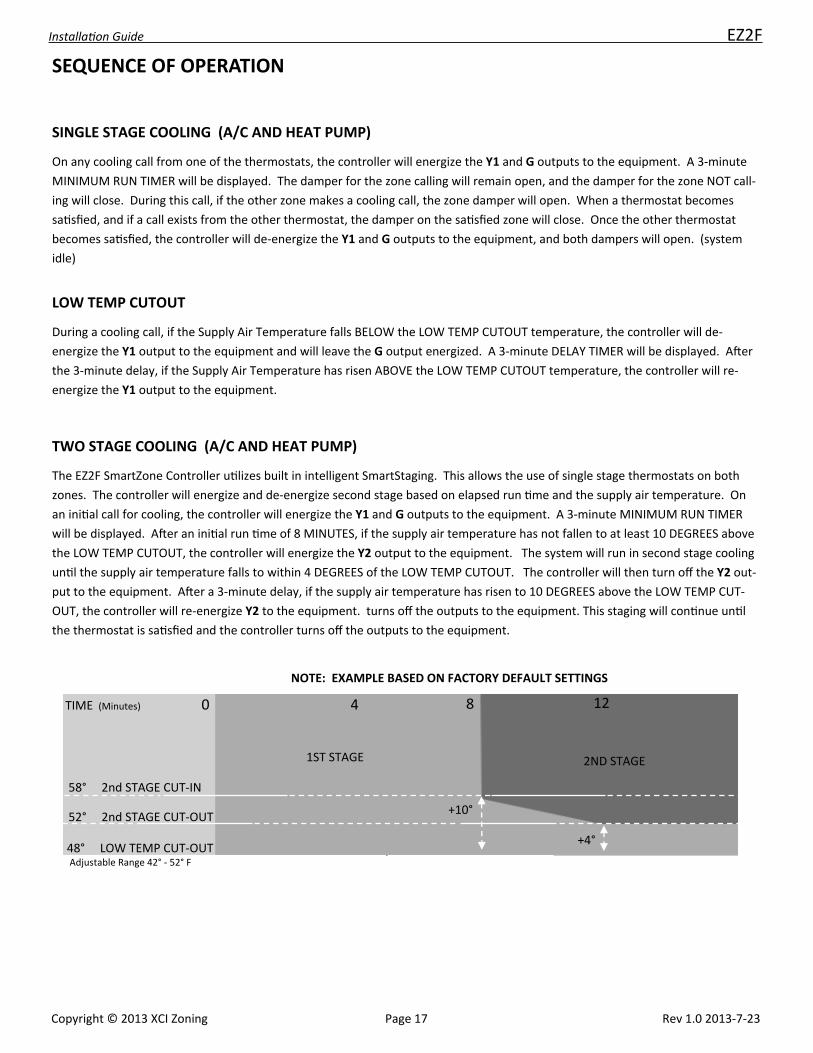
TWO STAGE COOLING (A/C AND HEAT PUMP)
The EZ2F SmartZone Controller u lizes built in intelligent SmartStaging. This allows the use of single stage thermostats on both
zones. The controller will energize and de‐energize second stage based on elapsed run me and the supply air temperature. On
an ini al call for cooling, the controller will energize the Y1 and G outputs to the equipment. A 3‐minute MINIMUM RUN TIMER
will be displayed. A er an ini al run me of 8 MINUTES, if the supply air temperature has not fallen to at least 10 DEGREES above
the LOW TEMP CUTOUT, the controller will energize the Y2 output to the equipment. The system will run in second stage cooling
un l the supply air temperature falls to within 4 DEGREES of the LOW TEMP CUTOUT. The controller will then turn off the Y2 out‐
put to the equipment. A er a 3‐minute delay, if the supply air temperature has risen to 10 DEGREES above the LOW TEMP CUT‐
OUT, the controller will re‐energize Y2 to the equipment. turns off the outputs to the equipment. This staging will con nue un l
the thermostat is sa sfied and the controller turns off the outputs to the equipment.
TIME (Minutes) 0 4 8 12
58° 2nd STAGE CUT‐IN
52° 2nd STAGE CUT‐OUT
48° LOW TEMP CUT‐OUT
+10°
+4°
1ST STAGE 2ND STAGE
NOTE: EXAMPLE BASED ON FACTORY DEFAULT SETTINGS
Adjustable Range 42° ‐ 52° F
Copyright © 2013 XCI Zoning Page 17 Rev 1.0 2013‐7‐23

Installa on Guide EZ2F
SINGLE STAGE HEATING (GAS & ELECTRIC HEAT / NOT HEATPUMP)
On any hea ng call from one of the thermostats, the controller will energize the W1 output to the equipment. A er 90 SECONDS
of ini al run me, the controller will energize the G output to the equipment. If the supply air temperature rises above the HI
TEMP CUTOUT se ng, the controller will de‐energize the W1 output to the equipment. A er a 3‐minute me delay, if a call s ll
exists and the supply air temperature has fallen below the HI TEMP CUTOUT, the controller will re‐energize the W1 output to the
equipment.
TWO STAGE HEATING (GAS & ELECTRIC HEAT / NOT HEATPUMP)
On any hea ng call from one of the thermostats, the controller will energize the W1 output to the equipment. A er 90 SECONDS
of ini al run me, the controller will energize the G output to the equipment. A er 8 MINUTES of ini al run me, if the supply air
temperature has not risen to at least 25 DEGREES BELOW the HI TEMP CUTOUT, the controller will energize W2 to the equipment.
The system will run in second stage hea ng un l the supply air temperature rises to 10 DEGREES below the HI TEMP CUTOUT. The
controller will then de‐energize W2. If the supply air temperature falls to 25 DEGREES below the HI TEMP CUTOUT, the controller
will re‐energize W2. This staging will con nue un l the thermostat is sa sfied and the controller turns off the equipment.
135° HI TEMP CUT‐OUT
125° 2nd STAGE CUT‐OUT
110° 2nd STAGE CUT‐IN
TIME (Minutes) 0
NOTE: EXAMPLE BASED ON FACTORY DEFAULT SETTINGS
‐25°
‐10°
4 8 12
Adjustable Range 125° ‐ 150° F
1ST STAGE 2ND STAGE
SEQUENCE OF OPERATION
Copyright © 2013 XCI Zoning Page 18 Rev 1.0 2013‐7‐23

Installa on Guide EZ2F
SINGLE STAGE HEATING ‐ HEATPUMP
On any hea ng call from one of the thermostats (Y if using heat pump thermostats, W if using gas/electric thermostats) the con‐
troller will energize the Y1 and G outputs to the equipment. A 3‐minute minimum run mer will be displayed. A er 6 MINUTES of
ini al run me (Factory default. Adjustable 3‐6 minutes) if the supply air temperature has not reached 90 DEGREES (Factory de‐
fault. Adjustable 90‐100°) the controller will energize the W1 output to the equipment (Auxiliary Heat). The equipment will con‐
nue to run in AUXILIARY HEAT un l the supply air temperature rises to 10 DEGREES above the AUXILIARY HEAT CUT‐IN TEMPERA‐
TURE. (Adjusts with Aux. Heat Cut‐In Se ng). The controller will con nue to stage auxiliary heat on and off based on supply air
temperature. If the supply air temperature rises above the HI TEMP CUT‐OUT temperature, the controller will de‐energize the Y1
output to the equipment and leave the G output energized. A 3‐minute compressor delay mer will be displayed. A er 3
minutes, if the supply air temperature has fallen below the HI TEMP CUT‐OUT temperature, the controller will re‐energize the Y1
output to the equipment. See staging chart below.
TWO STAGE HEATING ‐ HEATPUMP
On any hea ng call from one of the thermostats (Y if using heatpump thermostats, W if using gas/electric thermostats) the con‐
troller will energize the Y1 and G outputs to the equipment. A er 4 minutes of ini al run me, if the supply air temperature has
not reached 105 DEGREES (15 degrees below the HIGH TEMP CUTOUT) , the controller will energize Y2 to the equipment. Y2 will
remain energized un l the supply air temperature reaches 115 DEGREES (5 degrees below the HIGH TEMP CUTOUT). The control‐
ler will then de‐energize Y2. The controller will con nue to stage Y2 on and off based on the supply air temperature. A er
6 MINUTES of ini al run me, if the supply air has not reached at least 90 DEGREES, the controller will energize W1 to turn on
auxiliary heat. W1 will remain energized un l the supply air temperature reaches 100 DEGREES (20 degrees below the HIGH
TEMP CUTOUT). See staging chart below. NOTE: AUX HEAT TIME AND TEMPERATURE STAGING IS NOT MANUALLY ADJUSTABLE
ON TWO‐SPEED HEAT PUMP EQUIPMENT. THE SECOND STAGE AND AUX HEAT STAGING TEMPERATURES MOVE UP AND
DOWN BASED ON THE HIGH TEMP CUTOUT SETTING.
120° HI TEMP CUT‐OUT
115° 2nd STAGE CUT‐OUT
105° 2nd STAGE CUT‐IN
100° AUX. HEAT CUT‐OUT
90° AUX. HEAT CUT‐IN
TIME (Minutes) 0 2 4 6 8
‐15°
‐5°
1ST STAGE
2ND STAGE AUX HEAT
ELECTRIC HEAT PUMP WITH ELECTRIC AUXILIARY HEAT (FACTORY DEFAULT TEMPERATURE SETTINGS)
90‐100° Adjustable Range on 3‐6 Minutes Adjustable Stage‐In
NOTE: EXAMPLE BASED ON FACTORY DEFAULT SETTINGS
SEQUENCE OF OPERATION
Copyright © 2013 XCI Zoning Page 19 Rev 1.0 2013‐7‐23

Installa on Guide EZ2F
SEQUENCE OF OPERATION
DUAL FUEL HEAT PUMP
SINGLE STAGE AND 2‐STAGE COOLING
Single Stage and 2‐Stage cooling operates the same on all system types. REFER TO PAGE 16.
Copyright © 2013 XCI Zoning Page 20 Rev 1.0 2013‐7‐23
SINGLE STAGE HEATING (DUAL FUEL HEAT PUMP)
On any hea ng call from one of the thermostats (Y if using heat pump thermostats [B with Y if Op on #07 is set to B], W if using
gas/electric thermostats) the controller will energize the Y1 and G [and B is Op on #07 is set to B] outputs to the equipment. A 3‐
minute minimum run mer will be displayed. A er 6 MINUTES of ini al run me (Factory default. Adjustable 3‐6 minutes) if the
supply air temperature has not reached 90 DEGREES (Factory default. Adjustable 90‐100°) the controller will de‐energize the Y1
output to the equipment and energize the W1 output to the equipment (Auxiliary Heat). The equipment will con nue to run in
AUXILIARY HEAT un l the thermostat(s) calling is sa sfied. If the supply air temperature rises ABOVE the HIGH TEMP CUTOUT, the
controller will turn off W1 to the equipment. The fan will con nue to run. A er a 3‐minute delay, if a call s ll exists and the supply
air temperature has fallen BELOW the high temp cutout, the controller will re‐energize W1 to the equipment. ONCE THE CON‐
TROLLER HAS SWITCHED TO AUXILIARY HEAT, THE CONTROLLER WILL STAY IN AUXILIARY HEAT UNTIL ALL CALLS ARE SATISFIED.
TWO STAGE HEATING (DUAL FUEL HEAT PUMP)
On any hea ng call from one of the thermostats (Y if using heat pump thermostats [B with Y if Op on #07 is set to B], W if using
gas/electric thermostats) the controller will energize the Y1 and G [and B is Op on #07 is set to B] outputs to the equipment. A er
4 minutes of ini al run me, if the supply air temperature has not reached 105 DEGREES (15 degrees below the HIGH TEMP CUT‐
OUT) , the controller will energize Y2 to the equipment. Y2 will remain energized un l the supply air temperature reaches 115 DE‐
GREES (5 degrees below the HIGH TEMP CUTOUT). The controller will then de‐energize Y2. The controller will con nue to stage Y2
on and off based on the supply air temperature. A er 6 MINUTES of ini al run me, if the supply air has not reached at least 90
DEGREES, the controller will de‐ energize Y1 and Y2 and energize W1 to turn on auxiliary heat. W1 will remain energized un l the
thermostat(s) calling is sa sfied. If the supply air temperature rises ABOVE the HIGH TEMP GAS CUTOUT, the controller will turn
off W1 to the equipment. The fan will con nue to run. A er a 3‐minute delay, if a call s ll exists and the supply air temperature
has fallen BELOW the high temp cutout, the controller will re‐energize W1 to the equipment. ONCE THE CONTROLLER HAS
SWITCHED TO AUXILIARY HEAT, THE CONTROLLER WILL STAY IN AUXILIARY HEAT UNTIL ALL CALLS ARE SATISFIED.
NOTE: AUX HEAT TIME AND TEMPERATURE STAGING IS NOT MANUALLY ADJUSTABLE ON TWO‐SPEED HEAT PUMP EQUIPMENT.
THE SECOND STAGE AND AUX HEAT STAGING TEMPERATURES MOVE UP AND DOWN BASED ON THE HIGH TEMP CUTOUT SET‐
TING.
TIME (Minutes) 0 2 4 6 8
90° AUX HEAT CUT‐IN
(Adj. Range 90‐100° SINGLE STAGE ONLY)
105° 2nd STAGE CUT‐IN
115° 2nd STAGE CUT‐OUT
120° HI‐TEMP HEAT PUMP CUT‐OUT
135° HI‐TEMP GAS/AUX HEAT CUT‐OUT
1ST STAGE 2ND STAGE AUX HEAT (GAS FURNACE)
NOTE: EXAMPLES BASED ON FACTORY DEFAULT SETTINGS
‐15°
‐5°

Installa on Guide EZ2F
Copyright © 2013 XCI Zoning Page 21 Rev 1.0 2013‐7‐23
SMARTZONE FEATURES
EMERGENCY HEAT ‐ HEAT PUMP AND DUAL FUEL
Emergency heat can ONLY be ini ated by a HEAT PUMP THERMOSTAT connected to the ZONE 1 thermostat input. A HEAT PUMP THERMOSTAT SHOULD
ALWAYS be used for the ZONE 1 thermostat in heat pump applica ons. If the ZONE 1 thermostat calls for EMERGENCY HEAT, the SmartZone controller will be
LOCKED into emergency heat (AUX HEAY). ANY call for heat from either zone will turn on auxiliary heat. The controller can be UNLOCKED by making a call for
compressor (heat or cool) from the Zone 1 thermostat.
AUTO CHANGEOVER
It is possible to have one zone calling for cooling and the other zone calling for hea ng (opposing calls). When an opposing call occurs, a CHANGEOVER TIMER
(10 or 15 minutes ‐ Adjustable) will display on the screen. A er the mer has reached zero, the system will go into PURGE MODE for 3‐MINUTES. (See PURGE
mode below). At the end of the 3‐minute purge, the system will switch over to the other mode. If an opposing call s ll exists, the CHANGOVER TIMER will
restart.
PURGE
Purge occurs whenever the system is running with only one zone calling, and the other zone makes an opposing call. A er the changeover me has elapsed
the controller turns off the equipment and leaves the fan (G) energized. The last zone calling will remain open during the 3 MINUTE purge (countdown mer dis‐
played on screen). This allows the temperature in the ductwork to equalize before star ng the opposing call.
MINIMUM RUN TIME ‐ COMPRESSOR
The SmartZone Controller features a MINIMUM RUN TIME any me Y1 in energized to the equipment. This protects the compressor from damage caused by short‐
cycling. A 3‐MINUTE MIN RUN mer is displayed on the screen each me the compressor is started.
TIME DELAY
The SmartZone Controller features a TIME DELAY MODE that is designed to protect the compressor from short cycling. The me delay is ini ated each me the
compressor is de‐energized. A 3‐MINUTE DELAY mer will be displayed on the screen during this me. The compressor CANNOT be restarted un l the mer has
counted down to zero. In addi on, if using a GAS FURNACE and the supply air temperature rises ABOVE the high temp limit, the controller will de‐energize W1 and
keep G energized. A 3‐MINUTE DELAY mer will be displayed on the screen during this me.
EXCLUSIVE EQUIPMENT TEST MODE
The SmartZone Controller can be put into an EQUIPMENT TEST MODE by powering the controller. A er the IDLE screen appears, hold down the RESET BUTTON,
then hold down the SETUP BUTTON, release the RESET BUTTON and then release the SETUP BUTTON. The controller will display TEST ‐ IDLE ‐EC. The controller will
now only accept calls form the ZONE 1 thermostat, and will not operate the dampers. This allows the installer to set the bypass damper, check the refrigerant
charge on the system and verify proper airflow thru the system. A er all tes ng is complete, press and release the RESET bu on. The controller will reset and go
into IDLE mode awai ng calls.
ECONOMY MODE
The ECONOMY MODE (EC) input on the ZONE 1 TSTAT connector allows the use of a switch, occupancy sensor or dry contact to apply 24 VAC input to the EC termi‐
nal to put the controller into ECONOMY MODE. This prevents ZONE 2 from making equipment calls. ZONE 2 will only be able to open and close the damper. Only
ZONE 1 will be able to make equipment calls.
RH/RC JUMPER
The RH/RC Jumper is factory installed on the SmartZone Controller. If the equipment requires separate transformers for hea ng and cooling, REMOVE the jumper
[JP1] located next to the “C” equipment connector. NOTE: The jumper should NOT be removed for heat pump systems.
FRESH AIR CONTROL ‐ OPTION#16
The SmartZone EZ2F Controller features on board Fresh Air Control. A 2‐wire or 3‐wire damper may be used. The mer is adjustable from 5 to 60 minutes per hour
in 5 minute increments. The controller will open the fresh air damper any me the controller energizes the G terminal to the equipment as long as minutes per hour
remain. At the end of the hour, if run me minutes s ll exist (displayed on screen), the controller will turn on the G terminal to the equipment, open the fresh air
damper, leave the zone dampers open and run un l the remaining minutes have elapsed.
EXCLUSIVE FRESH AIR SENSOR MODE ‐ OPTION #17
An outdoor Fresh Air Sensor may be plugged into the controller. By turning on Op on #17, a LOW (Op on #18) and HIGH (Op on #19) temperature limit for fresh
air can be set. The low temp se ng has a factory default se ng of 20° F and an adjustable range of 20° ‐ 40° F. The high‐temp se ng has a factory default se ng
of 80° F and an adjustable range of 60° ‐ 80° F.

Installa on Guide EZ2F
Copyright © 2013 XCI Zoning Page 22 Rev 1.0 2013‐7‐23
DISABLE AUX HEAT STAGING ‐ HEAT PUMP AND DUAL FUEL HEATPUMP ‐ OPTION #24
The EZ2F Smartzone Controller has the ability disable automa c auxiliary heat staging if the outdoor temperature is above 40° F.
DUAL FUEL LOW TEMP LOCKOUT ‐ OPTION #20
When using Dual Fuel Equipment, a Fresh Air Sensor is REQUIRED for proper opera on. Op on #20 allows the se ng of an Outdoor Lock‐out Temperature that will
prevent the heat pump from running in extremely low temperatures. The factory default se ng is 30° F. The adjustable range is 20° ‐ 50° F. When the outdoor
temperature is BELOW the Lock‐Out Temperature se ng, the controller will turn on the gas furnace for all hea ng calls.
EXPANSION MODE ‐ SLAVE ‐ OPTION #01
The EZ2F Smartzone Controller can be used as a 2‐zone expansion module for larger systems. Op on #01 allows the controller to be set as a SLAVE expansion mod‐
ule. The zoning system can be expanded with up to 9 expansion modules, with a total capacity of 40 zones. Each SLAVE module requires an individual address (1‐9)
to be entered at Op on #02. Communica on is accomplished by use of a SmartLink Cable plugged into the 3‐pole Smart Link receptacle at the bo om of each
board. For systems with more than 1 expansion module, the communica on cables are daisy‐chained.
SMARTZONE FEATURES
ZONE 1 THERMOSTAT STAGING ‐ OPTION #25
On 2‐stage systems, a 2‐stage thermostat may be installed and used on Zone 1. When Op on #25 is turned ON, the Zone 1 thermostat can ini ate 2nd stage
hea ng or cooling a er an ini al 1 minute minimum run me. This se ng also overrides 2nd stage lockout (Op on #21) for Zone 1.
SECOND STAGE LOCKOUT ‐ OPTION #21
On 2‐stage systems, if Op on #21 is enabled the controller will not go into second stage with only one zone calling. Both zones MUST be calling for the controller to
bring on 2nd stage.
THERMOSTAT TYPE ‐ OPTION #06
When using Heat Pump Equipment, the controller allows the use of either Single‐Stage Gas/Electric OR Single‐Stage Heat Pump thermostats. When electric heat
pump or dual fuel system is selected as the System Type (Op on #03) the controller will prompt to select what type of thermostat is being used. Calls from gas/
electric thermostats are recognized by the controller and the appropriate equipment terminals are energized. NOTE: A heat pump thermostat with an emergency
heat switch is REQUIRED on Zone 1 in order to turn on EMERGENCY HEAT if needed. Once emergency heat has been ini ated, the controller is “LATCHED” into
emergency heat. All calls from ALL thermostat will turn on emergency (auxiliary) heat. The controller can only be “UNLATCHED” by making a compressor call
(Y in either hea ng or cooling). A er the board is unlatched, the controller reverts to normal heat pump opera on.
ECONOMIZER MODE ‐ OPTION #14
When the Economizer Mode is turned on, the controller will open the economizer and turn on G to the equipment if the outdoor temperature is below the Econo‐
mizer Outdoor Setpoint (Op on #15 ‐ 55° F factory default. Adjustable range 50° ‐ 75° F). During the cooling call, if the outdoor temperature rises ABOVE the out‐
door setpoint, the controller will close the economizer and turn on mechanical cooling.
Floor BEDROOMS
Area 0‐1 2‐3 4‐5 6‐7 >7
< 1500 30 45 60 75 90
1501 ‐ 3000 45 60 75 90 105
3001 ‐ 4500 60 75 90 105 120
4501 ‐ 6000 75 90 105 120 135
6001 ‐ 7500 90 105 120 135 150
> 7500 105 120 135 150 165
ASHRAE 62.2
1 DETERMINE THE FRESH AIR CFM TO COMPLY WITH ASHRAE 62.2 USING THE TABLE BELOW OR THIS FORMULA:
[(TOTAL SQ. FT.) /100]
+[(# OF BEDROOMS+1) X 7.5]
FRESH AIR CFM
2 MEASURE THE CFM PROVIDED BY THE FRESH AIR DAMPER WITH AN ANEMOMETER
3 CALCULATE FRESH AIR RUN TIME AND SET THIS NUMBER AT OPTION #16
FRESH AIR RUN TIME = 60 X FRESH AIR CFM_
MEASURED ‐ CFM