Extreme Management Center Wireless Manager User Guide
260
Extreme Networks Extreme Management Center ® Wireless Manager User Guide
Transcript of Extreme Management Center Wireless Manager User Guide

Extreme Networks ExtremeManagement Center®Wireless Manager User Guide


- i -
Copyright © 2016 Extreme Networks, Inc. All Rights Reserved.
Legal Notices
Extreme Networks, Inc., on behalf of or through its wholly-owned subsidiary,Enterasys Networks, Inc., reserves the right to make changes in specificationsand other information contained in this document and its website without priornotice. The reader should in all cases consult representatives of ExtremeNetworks to determine whether any such changes have been made.
The hardware, firmware, software or any specifications described or referred toin this document are subject to change without notice.
Trademarks
Extreme Networks and the Extreme Networks logo are trademarks or registeredtrademarks of Extreme Networks, Inc. in the United States and/or othercountries.
All other names (including any product names) mentioned in this document arethe property of their respective owners and may be trademarks or registeredtrademarks of their respective companies/owners.
For additional information on Extreme Networks trademarks, please see:www.extremenetworks.com/company/legal/trademarks/
Support
For product support, including documentation, visit:www.extremenetworks.com/support/
Contact
Extreme Networks, Inc.,145 Rio RoblesSan Jose, CA 95134Tel: +1 408-579-2800
Toll-free: +1 888-257-3000

- ii -
Extreme Networks® Software License Agreement
This Extreme Networks Software License Agreement is an agreement("Agreement") between You, the end user, and Extreme Networks, Inc.("Extreme"), on behalf of itself and its Affiliates (as hereinafter defined andincluding its wholly owned subsidiary, Enterasys Networks, Inc. as well as itsother subsidiaries). This Agreement sets forth Your rights and obligations withrespect to the Licensed Software and Licensed Materials. BY INSTALLING THELICENSE KEY FOR THE SOFTWARE ("License Key"), COPYING, OROTHERWISE USING THE LICENSED SOFTWARE, YOU ARE AGREEING TOBE BOUND BY THE TERMS OF THIS AGREEMENT, WHICH INCLUDES THELICENSE AND THE LIMITATION OF WARRANTY AND DISCLAIMER OFLIABILITY. IF YOU DO NOT AGREE TO THE TERMS OF THIS AGREEMENT,RETURN THE LICENSE KEY TO EXTREME OR YOUR DEALER, IF ANY, ORDO NOT USE THE LICENSED SOFTWARE AND CONTACT EXTREME ORYOUR DEALER WITHIN TEN (10) DAYS FOLLOWING THE DATE OF RECEIPTFOR A REFUND. IF YOU HAVE ANY QUESTIONS ABOUT THIS AGREEMENT,CONTACT EXTREME, Attn: [email protected].
1. DEFINITIONS. "Affiliates" means any person, partnership, corporation,limited liability company, or other form of enterprise that directly or indirectlythrough one or more intermediaries, controls, or is controlled by, or is undercommon control with the party specified. "Server Application" shall refer tothe License Key for software installed on one or more of Your servers. "ClientApplication" shall refer to the application to access the Server Application. "Licensed Materials" shall collectively refer to the licensed software(including the Server Application and Client Application), Firmware, mediaembodying the software, and the documentation. "Concurrent User" shallrefer to any of Your individual employees who You provide access to theServer Application at any one time. "Firmware" refers to any softwareprogram or code imbedded in chips or other media. "Licensed Software"refers to the Software and Firmware collectively.
2. TERM. This Agreement is effective from the date on which You install theLicense Key, use the Licensed Software, or a Concurrent User accesses theServer Application. You may terminate the Agreement at any time bydestroying the Licensed Materials, together with all copies, modifications

- iii -
and merged portions in any form. The Agreement and Your license to usethe Licensed Materials will also terminate if You fail to comply with any termof condition herein.
3. GRANT OF SOFTWARE LICENSE. Extreme will grant You a non-transferable, non-exclusive license to use the machine-readable form of theLicensed Software and the accompanying documentation if You agree tothe terms and conditions of this Agreement. You may install and use theLicensed Software as permitted by the license type purchased as describedbelow in License Types. The license type purchased is specified on theinvoice issued to You by Extreme or Your dealer, if any. YOU MAY NOT USE,COPY, OR MODIFY THE LICENSED MATERIALS, IN WHOLE OR IN PART,EXCEPT AS EXPRESSLY PROVIDED IN THIS AGREEMENT.
4. LICENSE TYPES.
l Single User, Single Computer. Under the terms of the Single User, SingleComputer license, the license granted to You by Extreme when Youinstall the License Key authorizes You to use the Licensed Software onany one, single computer only, or any replacement for that computer, forinternal use only. A separate license, under a separate Software LicenseAgreement, is required for any other computer on which You or anotherindividual or employee intend to use the Licensed Software. A separatelicense under a separate Software License Agreement is also required ifYou wish to use a Client license (as described below).
l Client. Under the terms of the Client license, the license granted to Youby Extreme will authorize You to install the License Key for the LicensedSoftware on your server and allow the specific number of ConcurrentUsers shown on the relevant invoice issued to You for each ConcurrentUser that You order from Extreme or Your dealer, if any, to access theServer Application. A separate license is required for each additionalConcurrent User.
5. AUDIT RIGHTS. You agree that Extreme may audit Your use of the LicensedMaterials for compliance with these terms and Your License Type at anytime, upon reasonable notice. In the event that such audit reveals any use ofthe Licensed Materials by You other than in full compliance with the licensegranted and the terms of this Agreement, You shall reimburse Extreme for allreasonable expenses related to such audit in addition to any other liabilitiesYou may incur as a result of such non-compliance, including but not limitedto additional fees for Concurrent Users over and above those specificallygranted to You. From time to time, the Licensed Software will uploadinformation about the Licensed Software and the associated devices to

- iv -
Extreme. This is to verify the Licensed Software is being used with a validlicense. By using the Licensed Software, you consent to the transmission ofthis information. Under no circumstances, however, would Extreme employany such measure to interfere with your normal and permitted operation ofthe Products, even in the event of a contractual dispute.
6. RESTRICTION AGAINST COPYING OR MODIFYING LICENSEDMATERIALS. Except as expressly permitted in this Agreement, You may notcopy or otherwise reproduce the Licensed Materials. In no event does thelimited copying or reproduction permitted under this Agreement include theright to decompile, disassemble, electronically transfer, or reverse engineerthe Licensed Software, or to translate the Licensed Software into anothercomputer language.
The media embodying the Licensed Software may be copied by You, inwhole or in part, into printed or machine readable form, in sufficient numbersonly for backup or archival purposes, or to replace a worn or defective copy. However, You agree not to have more than two (2) copies of the LicensedSoftware in whole or in part, including the original media, in your possessionfor said purposes without Extreme’s prior written consent, and in no eventshall You operate more copies of the Licensed Software than the specificlicenses granted to You. You may not copy or reproduce thedocumentation. You agree to maintain appropriate records of the locationof the original media and all copies of the Licensed Software, in whole or inpart, made by You. You may modify the machine-readable form of theLicensed Software for (1) your own internal use or (2) to merge the LicensedSoftware into other program material to form a modular work for your ownuse, provided that such work remains modular, but on termination of thisAgreement, You are required to completely remove the Licensed Softwarefrom any such modular work. Any portion of the Licensed Softwareincluded in any such modular work shall be used only on a single computerfor internal purposes and shall remain subject to all the terms and conditionsof this Agreement. You agree to include any copyright or other proprietarynotice set forth on the label of the media embodying the Licensed Softwareon any copy of the Licensed Software in any form, in whole or in part, or onany modification of the Licensed Software or any such modular workcontaining the Licensed Software or any part thereof.
7. TITLE AND PROPRIETARY RIGHTS
a. The Licensed Materials are copyrighted works and are the sole andexclusive property of Extreme, any company or a division thereof whichExtreme controls or is controlled by, or which may result from the mergeror consolidation with Extreme (its "Affiliates"), and/or their suppliers.

- v -
This Agreement conveys a limited right to operate the Licensed Materialsand shall not be construed to convey title to the Licensed Materials toYou. There are no implied rights. You shall not sell, lease, transfer,sublicense, dispose of, or otherwise make available the LicensedMaterials or any portion thereof, to any other party.
b. You further acknowledge that in the event of a breach of thisAgreement, Extreme shall suffer severe and irreparable damages forwhich monetary compensation alone will be inadequate. You thereforeagree that in the event of a breach of this Agreement, Extreme shall beentitled to monetary damages and its reasonable attorney’s fees andcosts in enforcing this Agreement, as well as injunctive relief to restrainsuch breach, in addition to any other remedies available to Extreme.
8. PROTECTION AND SECURITY. In the performance of this Agreement or incontemplation thereof, You and your employees and agents may haveaccess to private or confidential information owned or controlled by Extremerelating to the Licensed Materials supplied hereunder including, but notlimited to, product specifications and schematics, and such information maycontain proprietary details and disclosures. All information and data soacquired by You or your employees or agents under this Agreement or incontemplation hereof shall be and shall remain Extreme’s exclusive property,and You shall use your best efforts (which in any event shall not be less thanthe efforts You take to ensure the confidentiality of your own proprietary andother confidential information) to keep, and have your employees andagents keep, any and all such information and data confidential, and shallnot copy, publish, or disclose it to others, without Extreme’s prior writtenapproval, and shall return such information and data to Extreme at itsrequest. Nothing herein shall limit your use or dissemination of informationnot actually derived from Extreme or of information which has been orsubsequently is made public by Extreme, or a third party having authority todo so. You agree not to deliver or otherwise make available the LicensedMaterials or any part thereof, including without limitation the object orsource code (if provided) of the Licensed Software, to any party other thanExtreme or its employees, except for purposes specifically related to youruse of the Licensed Software on a single computer as expressly provided inthis Agreement, without the prior written consent of Extreme. You agree touse your best efforts and take all reasonable steps to safeguard the LicensedMaterials to ensure that no unauthorized personnel shall have access theretoand that no unauthorized copy, publication, disclosure, or distribution, inwhole or in part, in any form shall be made, and You agree to notify Extreme

- vi -
of any unauthorized use thereof. You acknowledge that the LicensedMaterials contain valuable confidential information and trade secrets, andthat unauthorized use, copying and/or disclosure thereof are harmful toExtreme or its Affiliates and/or its/their software suppliers.
9. MAINTENANCE AND UPDATES. Updates and certain maintenance andsupport services, if any, shall be provided to You pursuant to the terms of anExtreme Service and Maintenance Agreement, if Extreme and You enter intosuch an agreement. Except as specifically set forth in such agreement,Extreme shall not be under any obligation to provide Software Updates,modifications, or enhancements, or Software maintenance and supportservices to You.
10. DEFAULT AND TERMINATION. In the event that You shall fail to keep,observe, or perform any obligation under this Agreement, including a failureto pay any sums due to Extreme, or in the event that you become insolventor seek protection, voluntarily or involuntarily, under any bankruptcy law,Extreme may, in addition to any other remedies it may have under law,terminate the License and any other agreements between Extreme and You.
a. Immediately after any termination of the Agreement or if You have forany reason discontinued use of Software, You shall return to Extreme theoriginal and any copies of the Licensed Materials and remove theLicensed Software from any modular works made pursuant to Section 3,and certify in writing that through your best efforts and to the best ofyour knowledge the original and all copies of the terminated ordiscontinued Licensed Materials have been returned to Extreme.
b. Sections 1, 7, 8, 10, 11, 12, 13, 14 and 15 shall survive termination of thisAgreement for any reason.
11. EXPORT REQUIREMENTS. You are advised that the Software is of UnitedStates origin and subject to United States Export AdministrationRegulations; diversion contrary to United States law and regulation isprohibited. You agree not to directly or indirectly export, import or transmitthe Software to any country, end user or for any Use that is prohibited byapplicable United States regulation or statute (including but not limited tothose countries embargoed from time to time by the United Statesgovernment); or contrary to the laws or regulations of any othergovernmental entity that has jurisdiction over such export, import,transmission or Use.
12. UNITED STATES GOVERNMENT RESTRICTED RIGHTS. The LicensedMaterials (i) were developed solely at private expense; (ii) contain"restricted computer software" submitted with restricted rights in

- vii -
accordance with section 52.227-19 (a) through (d) of the CommercialComputer Software-Restricted Rights Clause and its successors, and (iii) inall respects is proprietary data belonging to Extreme and/or its suppliers. For Department of Defense units, the Licensed Materials are consideredcommercial computer software in accordance with DFARS section227.7202-3 and its successors, and use, duplication, or disclosure by the U.S.Government is subject to restrictions set forth herein.
13. LIMITED WARRANTY AND LIMITATION OF LIABILITY. The only warrantythat Extreme makes to You in connection with this license of the LicensedMaterials is that if the media on which the Licensed Software is recorded isdefective, it will be replaced without charge, if Extreme in good faithdetermines that the media and proof of payment of the license fee arereturned to Extreme or the dealer from whom it was obtained within ninety(90) days of the date of payment of the license fee.NEITHER EXTREME NOR ITS AFFILIATES MAKE ANY OTHER WARRANTYOR REPRESENTATION, EXPRESS OR IMPLIED, WITH RESPECT TO THELICENSED MATERIALS, WHICH ARE LICENSED "AS IS". THE LIMITEDWARRANTY AND REMEDY PROVIDED ABOVE ARE EXCLUSIVE AND INLIEU OF ALL OTHER WARRANTIES, INCLUDING IMPLIED WARRANTIESOF MERCHANTABILITY OR FITNESS FOR A PARTICULAR PURPOSE,WHICH ARE EXPRESSLY DISCLAIMED, AND STATEMENTS ORREPRESENTATIONS MADE BY ANY OTHER PERSON OR FIRM ARE VOID. ONLY TO THE EXTENT SUCH EXCLUSION OF ANY IMPLIED WARRANTYIS NOT PERMITTED BY LAW, THE DURATION OF SUCH IMPLIEDWARRANTY IS LIMITED TO THE DURATION OF THE LIMITED WARRANTYSET FORTH ABOVE. YOU ASSUME ALL RISK AS TO THE QUALITY,FUNCTION AND PERFORMANCE OF THE LICENSED MATERIALS. IN NOEVENT WILL EXTREME OR ANY OTHER PARTY WHO HAS BEENINVOLVED IN THE CREATION, PRODUCTION OR DELIVERY OF THELICENSED MATERIALS BE LIABLE FOR SPECIAL, DIRECT, INDIRECT,RELIANCE, INCIDENTAL OR CONSEQUENTIAL DAMAGES, INCLUDINGLOSS OF DATA OR PROFITS OR FOR INABILITY TO USE THE LICENSEDMATERIALS, TO ANY PARTY EVEN IF EXTREME OR SUCH OTHER PARTYHAS BEEN ADVISED OF THE POSSIBILITY OF SUCH DAMAGES. IN NOEVENT SHALL EXTREME OR SUCH OTHER PARTY'S LIABILITY FOR ANYDAMAGES OR LOSS TO YOU OR ANY OTHER PARTY EXCEED THELICENSE FEE YOU PAID FOR THE LICENSED MATERIALS.Some states do not allow limitations on how long an implied warranty lastsand some states do not allow the exclusion or limitation of incidental orconsequential damages, so the above limitation and exclusion may not apply

- viii -
to You. This limited warranty gives You specific legal rights, and You mayalso have other rights which vary from state to state.
14. JURISDICTION. The rights and obligations of the parties to this Agreementshall be governed and construed in accordance with the laws and in theState and Federal courts of the State of California, without regard to its ruleswith respect to choice of law. You waive any objections to the personaljurisdiction and venue of such courts. None of the 1980 United NationsConvention on the Limitation Period in the International Sale of Goods, andthe Uniform Computer Information Transactions Act shall apply to thisAgreement.
15. GENERAL.
a. This Agreement is the entire agreement between Extreme and Youregarding the Licensed Materials, and all prior agreements,representations, statements, and undertakings, oral or written, arehereby expressly superseded and canceled.
b. This Agreement may not be changed or amended except in writingsigned by both parties hereto.
c. You represent that You have full right and/or authorization to enter intothis Agreement.
d. This Agreement shall not be assignable by You without the expresswritten consent of Extreme. The rights of Extreme and Your obligationsunder this Agreement shall inure to the benefit of Extreme’s assignees,licensors, and licensees.
e. Section headings are for convenience only and shall not be considered inthe interpretation of this Agreement.
f. The provisions of the Agreement are severable and if any one or more ofthe provisions hereof are judicially determined to be illegal or otherwiseunenforceable, in whole or in part, the remaining provisions of thisAgreement shall nevertheless be binding on and enforceable by andbetween the parties hereto.
g. Extreme’s waiver of any right shall not constitute waiver of that right infuture. This Agreement constitutes the entire understanding betweenthe parties with respect to the subject matter hereof, and all prioragreements, representations, statements and undertakings, oral orwritten, are hereby expressly superseded and canceled. No purchaseorder shall supersede this Agreement.
h. Should You have any questions regarding this Agreement, You maycontact Extreme at the address set forth below. Any notice or other

- ix -
communication to be sent to Extreme must be mailed by certified mail tothe following address:
Extreme Networks, Inc.145 Rio RoblesSan Jose, CA 95134 United StatesATTN: General Counsel

- x -
Table of ContentsLegal Notices i
Trademarks i
Support i
Contact i
Extreme Networks® Software License Agreement ii
Table of Contents x
Wireless Manager Overview 1
Document Version 1
Legacy Template Migration Notice 2
Migrating Legacy Role and CoS Templates 2
Prerequisites 4
Getting Started with Wireless Manager 6
Configuring Controller Shared Secrets 6
Understanding the User Interface 8
Global Menu Bar 9
Global Button Bar 9
Breadcrumb Trail 10
Main Navigation Tabs 11
Navigation Tree 11
Context-Sensitive Toolbar 12
Content Pane 13
Event Tabs 13
Exporting a Configuration to the CLI 14
Managing Configured Objects 15
About Network Servers 16
- xi -
About NAC Servers 16
Creating a NAC Server Configuration 17
Server Details 18
NAC Details 19
Deployed To 19
Authentication 19
Health Monitoring 19
Authorize an actual new user (default): 19
Use RFC 5997 Status-Server Request: 19
NAC Log 20
Toolbar Buttons 20
Viewing Summary Information about Configured NAC Servers 20
Toolbar Buttons 21
Viewing Detailed Information about a Configured NAC Server 22
Server Details 23
NAC Details 23
Deployed To 23
Authentication 23
Toolbar Buttons 23
Modifying the NAC Server Configuration 24
Deleting the NAC Server Configuration 24
About RADIUS Servers 24
Creating a RADIUS Server Definition 25
Polling the Controllers for RADIUS Servers 25
Manually Creating a RADIUS Server Definition 25
Servers 26

- xii -
Authentication 27
Deployed To 27
Accounting 27
Health Monitoring 28
Authorize an actual new user (default): 28
Use RFC 5997 Status-Server Request: 28
RADIUS Server Log 28
Toolbar Buttons 28
Viewing a RADIUS Server Configuration 28
Toolbar Buttons 31
Editing the RADIUS Server Configuration 31
Deleting a RADIUS Server Configuration 32
About Network Topologies 33
Creating a Network Topology Configuration 34
General Settings 35
Manually Creating a Network Topology Configuration 35
Core 36
Layer 2 37
Layer 3 38
Deployed To 38
Topology Log 38
Toolbar Buttons 38
Multicast Filters 38
Configuring multicast filters for a Topology 39
Select Filter 40
Exception Filters 41

- xiii -
Per Controller L2/L3 Settings 45
Toolbar Buttons 47
Viewing Topology Summary Information 47
Toolbar Buttons 49
Editing a Topology 49
Deleting a Topology 50
About Wireless Networks 51
Shared Secrets Page 51
Viewing Mobility Zone Summary Information 52
Viewing Mobility Zone Details 56
Viewing Controller Summary Information 57
Toolbar Buttons 58
Viewing Controller Details 58
Core 59
Availability 60
Mobility 60
Controller Data Synchronization 60
Licensing 60
Toolbar Buttons 61
Adaptive Management UI 62
Browser Certificate Warnings 63
Chrome 63
Firefox 64
Internet Explorer 67
Accessing the Dashboard Page 67
Accessing the Logs Page 68

- xiv -
Accessing the Wireless Controller Configuration Page 69
Accessing the Wireless APs Page 70
Accessing the VNS Configuration Page 71
About Wireless Services 73
Viewing the Discovered SSIDs 73
Viewing Detailed Information About SSIDs 74
About AP Groups 76
Viewing a List of AP Groups 76
Toolbar Buttons 77
Viewing AP Groups Details 77
Toolbar Buttons 79
Creating an AP Group 79
Editing an AP Group 80
Deleting an AP Group 81
About AP Load Groups 82
Viewing the List of AP Load Groups 82
Toolbar Buttons 83
Viewing AP Load Groups Details 84
Template Properties Tab 84
Radio Assignment Tab 85
Radio Preference Tab 85
WLAN Assignment Tab 86
Toolbar Buttons 86
Creating an AP Load Group 86
Editing an AP Load Group 87
Deleting an AP Load Group 87

- xv -
Managing Templates 88
About Templates 89
Template Versions 89
Resolving Template Conflicts 90
Resolving Duplicate Templates 91
Editing Templates 93
Deleting Templates 94
Template Properties Tab 95
Toolbar Buttons 96
Viewing Detailed Template Information 97
About Globals Templates 98
Creating a Globals Template 98
Manually Creating a Globals Template 98
Administration Tab 99
System Logs Tab 101
Syslog Settings Tab 101
Web Settings Tab 102
Network Time Tab 102
Location Settings Tab 103
Authentication Settings Tab 104
Wireless QoS Tab 105
Topology Groups Settings Tab 106
Toolbar Buttons 106
Cloning Globals 107
Viewing Summary Information About All Globals Templates 107
Toolbar Buttons 109

- xvi -
About Virtual Network Service (VNS) Templates 110
Creating a VNS Template 110
Creating a VNS Configuration Using the VNS Wizard 111
Set Basic Settings Window 112
Define Privacy Settings 113
Set Authentication 113
Summary 113
Manually Creating a New VNS Configuration 113
Cloning an Existing VNS 115
Viewing Summary Information About All VNSs 115
Toolbar Buttons 117
About WLAN Service Templates 118
Creating a WLAN Service Template 118
Manually Creating a WLAN Service Template 119
WLAN Service Tab 120
Core 120
Status 121
Advanced Button 121
Privacy Tab 122
Auth & Acct Tab 122
Authentication 123
RADIUS Servers 124
VSAs 125
Zone Support 126
Optional TLVs 126
Operator Name 126

- xvii -
QoS Tab 128
Wireless QoS 128
Use Flexible Client Access 129
Advanced Wireless QoS 129
Advanced Button 129
Per Controller RADIUS/NAC Server Settings Tab 129
Per Controller Captive Portal Settings Tab 129
Per Controller Topology Settings Tab 130
Cloning an Existing WLAN Service 130
Viewing Summary Information About All WLAN Services Templates 130
Toolbar Buttons 132
Advanced QoS Settings Window 133
Advanced WLAN Service Settings Window 135
Timeout 137
RF 137
Egress Filtering Mode 138
Client Behavior 138
Remote Service 138
Inter-WLAN Service Roaming 138
Unauthenticated Behavior 138
Settings Window 140
Internal/Guest Portal/Guest Splash 140
Internal Authentication Mode Dialog 140
Guest Portal Authentication Mode Dialog 141
Guest Splash Authentication Mode Dialog 141
Login Credentials 142

- xviii -
Communication Options 142
Include Attributes 144
Provide button for users 144
802.1x with HTTP Redirection/External 144
Session Control Interface 145
Special 146
Firewall Friendly External Captive Portal 146
Redirect to External Captive Portal 146
Redirect From External Captive Portal 150
About Role Templates 152
Creating a Role Configuration Template 152
Migrating Legacy Role Templates 152
Using Policy Manager to Create Role Templates 153
Viewing Roles Summary Information 155
Viewing Detail Information About a Role 155
Default Policy Domain Tab 156
General Tab 157
Rules Tab 157
VLAN Egress Tab 157
Viewing Legacy Summary Information 157
Toolbar Buttons 159
Viewing Detail Information About a Legacy Role 159
VLAN and Class of Service Tab 159
Filters Rules Tab 159
Per Controller Settings Tab 161
About Rate Profiles 162

- xix -
Viewing Summary Information About All Rate Profiles 162
Toolbar Buttons 163
Viewing Detail Information About a Rate Profile 163
About AP Profiles 165
Creating an AP Profile Template 165
Manually Creating an AP Profile 165
AP Properties Tab 167
AP Properties Tab - Professional Install Button 168
AP Properties Tab - Advanced Button 168
Radio Settings Tab 170
Radio Settings Tab - Professional Install Button 173
Radio Settings Tab - Advanced Button 174
11b Settings 176
11g Settings 176
11n Settings 177
Enhanced Rate Control 178
No. of Retries 178
Cloning an Existing AP Profile 179
Configuring APs with Professionally Installed Antennas 180
Max Tx Power Calculations 182
Viewing Summary Information About All AP Profiles 182
Toolbar Buttons 184
About Classes of Service Templates 185
Creating a Class of Service Template 185
Using Policy Manager to Create Class of Service Templates 185
Viewing CoS Summary Information 187

- xx -
Viewing Detail Information About a CoS 188
Viewing Predefined CoS Information 189
Toolbar Buttons 191
Viewing Detail Information About a Predefined CoS 191
Viewing Legacy CoS Information 192
Viewing Detail Information About a Legacy CoS 194
Class of Service Properties Tab 195
Core 195
Marking 195
Rate Limiting 195
Transmit Queue Assignment 195
About Radar 196
In-Service Scan Profiles 196
Viewing Summary Information About In-Service Scan Profiles 197
Toolbar Buttons 198
Creating an In-Service Scan Profile 199
Manually Creating an In-Service Scan Profile 199
Detection tab 200
Core 200
Prevention Tab 200
Assigned APs Tab 200
Guardian Scan Profiles 200
Viewing Summary Information About Guardian Scan Profiles 201
Toolbar Buttons 202
Creating a Guardian Scan Profile 203
Manually Creating a Guardian Scan Profile 203

- xxi -
Detection Tab 204
Core 204
Channels to Monitor 204
Prevention Tab 204
Assigned APs Tab 204
Toolbar Buttons 205
Cloning an Existing Radar Profile 205
Radar Maintenance 205
Toolbar Buttons 207
AP Categories 207
Differences between the Radar Maintenance Template and OtherTemplates: 209
Manually Creating Radar Maintenance Template 209
Maintenance Tab 210
Security Threats 211
Rogue/Threat/Interference - Active & Inactive/Aged Events 212
Rogue Detection and Prevention 214
Rogue Detection 214
Rogue Testing 215
Rogue Prevention 216
Preventive Measures 216
Managing Tasks 218
About Tasks 219
Creating, Scheduling, and Deploying Tasks 220
Deploying a Template 221
Creating a Task 221

- xxii -
Deploying a Task 221
Select Item to Deploy Page 221
Enter Task Name 221
Select Targets and Deployment Time Page 221
Selecting Targets for VNS/WLAN Service Deployment 223
Selecting Targets for Remotable VNS/WLAN Service Deployment 223
Verify Targets 224
Specifying EWC Specific Settings 224
EWC Specific Topology Settings Page 224
EWC Specific RADIUS Servers Settings Page 225
EWC Specific Captive Portal Settings Page 225
Controller Specific Radar Settings 225
Verify AP Membership 226
Execute Task Page 226
Deploying Point of Presence 227
Deploying WLAN Service Assignments in Bulk 228
Monitoring Tasks 229
Viewing Task Status and Historical Summary Information 229
Toolbar Buttons 231
Viewing Task Details 231
Task Details Tab 232
Toolbar Buttons 233
Editing a Task 233
Deleting a Task 234
Rescheduling a Task 234
Reschedule Tasks Wizard 234

- xxiii -
Select the New Deployment Time Page 234
Execute Task Page 235
1 of 235
Wireless Manager Overview
Wireless Manager simplifies network configuration by enabling you to configureand manage multiple Wireless Controllers and their associated wireless APs.Using Wireless Manager wizards and configuration tools, you can create a newnetwork configuration or clone an existing one and apply that sameconfiguration to multiple Wireless Controllers and APs.
Wireless Manager compares the configuration in its deployed templates to theactual configuration of managed Wireless Controllers. Wireless Manager logs anevent and alerts you to any conflicts. Using the Conflict Resolution wizard, youcan easily identify and address any discrepancies between the deployedtemplates and the actual configuration.
For general information about Wireless Manager, see the following sections:
l Prerequisites
l Getting Started with Wireless Manager
l Understanding the User Interface
Document VersionThe following table displays the revision history for the Wireless Manager Helpdocumentation.
Date Revision Number Description
06-16 7.0 Revision -00 Extreme ManagementCenter (NetSight) 7.0release
07-15 6.3 Revision -00 NetSight 6.3 release
03-15 6.2 Revision -00 NetSight 6.2 release
06-14 6.1 Revision -00 NetSight 6.1 release
02-14 6.0 Revision -00 NetSight 6.0 release
PN: 9034993-01

2 of 235
Legacy Template Migration Notice
Wireless Manager no longer supports the configuration of Roles and Classes ofService (CoS). NetSight Policy Manager should be used for configuring Rolesand CoS. Each time Wireless Manager is opened, if there are any legacytemplates (Role, CoS, or Rate Profiles) defined, the following Legacy TemplateMigration notice appears:
The Legacy Template Migration notice indicates the number of days remainingbefore Wireless Manager terminates support for configuring Roles and CoS. Formore information on configuring Roles, see Using Policy Manager to Create aRole Template. For more information on configuring CoS, see Using PolicyManager to Create a CoS Template.
Migrating Legacy Role and CoS TemplatesIf you have any legacy Role and CoS templates, they must be migrated within 30days otherwise support will be terminated.
To migrate existing Role and CoS Templates:

Migrating Legacy Role and CoS Templates
3 of 235
1. Deploy your templates to the managed wireless controllers.
2. Using Policy Manager, assign your wireless controllers to a Policy domainand import their configuration. Select File > Import > Policy Configurationfrom Device.
3. From the Import from Device wizard, you must specify whether to importroles, rules, and/or class of services.
4. Save your changes.
5. Modify your Wireless Manager templates as needed to reference the newlycreated Role and CoS templates automatically imported from PolicyManager.
6. Remove the legacy templates. You can either delete the templates one-by-one or for your convenience use the following buttons displayed in theLegacy Template Migration dialog:
l Brute-Force Cleanup – Deletes all legacy templates whether or notthey are referenced by other templates. VNS templates may become"Incomplete". If Brute-Force Cleanup results in a VNS becoming"Incomplete", it will be displayed in the Conflict Resolution Wizard asa reminder for you to complete its definition and to specify a Non-Authenticated role for it.
l Best-Effort Cleanup – Deletes all legacy templates not referenced byother templates.
Please note these cleanup operations will even remove the legacypredefined CoS: Scavenger, Best Effort, Bulk Data, Critical Data, NetworkControl, Network Management, RTP/Voice/Video, and High Priority.However, upon synchronization with Policy Manager they will beautomatically re-created, and will be consistent with their Policy Managercounterparts.

4 of 235
Prerequisites
Before launching the Wireless Manager application, you should perform thefollowing tasks:
1. Install or upgrade the NetSight server software.
2. Install your NetSight license. (If you are not using the NMS-BASE, NMS, orNMS-ADV licensing model, you will also need to install your WirelessManager AP capacity licenses.) For licensing information, contact yourExtreme Networks sales representative.
3. Launch NetSight Console.
4. In NetSight Console, create a full administrator account to be used byWireless Manager to manage discovered Wireless Controllers.
5. Using the administrator credentials, create NetSight discovery profiles.
Ensure that Wireless Controllers are discovered using an SNMP v2c orSNMP v3 profile. This profile must also contain SSH CLI credentials for theWireless Controller. Wireless Manager uses the Wireless Controller’s CLI toretrieve required device configuration data and to configure the managedWireless Controllers.
To configure the CLI credentials:
a. From NetSight Console, access Tools > Authorization/DeviceAccess > Profiles/Credentials tab.
b. Select the CLI Credentials subtab.
c. Select the CLI Credential being used by the Wireless Controller’sProfile, and Click Edit.
d. Enter the user name and password to be used in the credential.For Wireless Controllers, you must add the Login password tothe Configuration field instead of the Login password field. Theusername and Configuration password specified here mustmatch the username and Login password configured on theWireless Controller.
e. Verify the SSH connection type is selected.
f. Click OK.
g. Use this CLI Credential in the Wireless Controller’s profile.

5 of 235
6. Discover Wireless Controllers using NetSight Console. Any WirelessControllers that you discover will be available for viewing and configurationin Wireless Manager.
7. Optionally, from Wireless Manager, you can change the Langley protocolshared secret that is used for mutual authentication between a WirelessController and Wireless Manager.

6 of 235
Getting Started with Wireless Manager
When you first launch Wireless Manager, the following settings are in effect:
l Any Wireless Controllers that you previously discovered in NetSight areavailable for viewing and configuration.
l Any Mobility Zones created on the Wireless Controllers are listed inWireless Manager.
l Any APs associated with the discovered Wireless Controllers are availablefor viewing and configuration. For each discovered Wireless Controller,Wireless Manager automatically creates a default AP group that includes allAPs approved and active as local APs on that Wireless Controller.
To view discovered network elements:
1. Click Configured Objects > Wireless Networks and explore the discoveredWireless Controllers, Mobility Zones, and APs.
2. Click Configured Objects > AP Groups to explore the default AP groupscreated.
Configuring Controller Shared SecretsAlthough you can immediately begin to configure your network afterdiscovering the Wireless Controllers, you should change the shared secret oneach Wireless Controller to provide additional security measures.
Wireless Manager uses a secure protocol called Langley to collect events andsome configuration data from managed Wireless Controllers. The protocol istransported through an SSL/TLS tunnel. Shared secrets are used to mutuallyauthenticate the two tunnel end points. Wireless Manager and WirelessControllers ship from the factory with a common well-known shared secret.Having a default shared secret facilitates initial deployments but, unless youchange the shared secrets, it can also provide a security risk because the sharedsecret is well known. Consequently, after Wireless Manager discovers a WirelessController, it is a best practice to change the shared secret used by WirelessManager and the Wireless Controller. You can configure Wireless Manager witha unique shared secret for each Wireless Controller managed by NetSight.
Configuring Controller Shared Secrets
7 of 235
You cannot change the shared secret for a Wireless Controller until the WirelessController has been discovered. If you change the shared secret you must do soboth on the Wireless Controller and on Wireless Manager.
To change the shared secret for a Wireless Controller, click Configured Objects >Wireless Networks > Generate Shared Secret and then assign/set the generatedsecret to the Wireless Controller.
Related Informationl Prerequisites
l Understanding the User Interface

8 of 235
Understanding the User Interface
The Wireless Manager user interface provides a way to configure and manageWireless Controllers and their associated APs. You navigate through the userinterface as you would a typical web page, using the following components:
l Global Menu Bar
l Global Button Bar
l Breadcrumb Trail
l Main Navigation Tabs
l Navigation Tree
l Context-Sensitive Toolbar
l Content Pane
l Event Tabs
The following graphic shows the Wireless Manager main user interface page.See below for descriptions of each of the main components.

Global Menu Bar
9 of 235
Global Menu BarThe global menu bar displays across each page within Wireless Manager. Usingthe global menu bar, you can launch online help, access other ManagementCenter tools, and perform Management Center management functions.
Global Button BarThe global button bar is displayed across the top of each page.
The following list describes the function for each button.
Click to exit Wireless Manager.
Breadcrumb Trail
10 of 235
Click to move backwards within Wireless Manager.
Click to move forward within Wireless Manager.
Click to configure user access to Extreme Management Center.
Click to view information about the Management Center server running theWireless Manager application.
Click to run a configuration audit. If the audit detects any conflicts, you canlaunch the Resolve Audit Conflicts wizard to resolve them.
Click to launch the Resolve Audit Conflicts wizard. Use this wizard to resolveany conflicts between Wireless Manager’s deployed templates and the actualWireless Controller and AP configuration.
Click to poll and import data from all managed Wireless Controllers including:VNS, Topologies, WLANs, RADIUS Servers, Load Groups, Default APProfiles, Global Settings, Radar Maintenance Settings and Scan Profiles.
Click to launch the Duplicate Resolution Wizard to detect and removeduplicate templates.
Click to view the online help for the page displayed in the right content pane.
Breadcrumb TrailUse the breadcrumb trail to identify the path to the current page displayed in theuser interface. The breadcrumb trail also displays an icon that shows the statusof a configured network element.

Main Navigation Tabs
11 of 235
Main Navigation TabsBelow the buttons at the top of the page, there are four main navigation tabsthat provide access to configuration information and settings for configuredobjects, templates, and tasks.
Following is a description of the functions of each navigation tab.
Configured ObjectsEnables you to view and configure RADIUS and NAC servers, WirelessControllers, network topologies, AP Groups and AP Load Groups. Inaddition, you can view information about Mobility Zones and wirelessservices.
TemplatesEnables you to view, create and manage configuration in the form oftemplates for Globals, VNSs, WLAN Services, Roles, CoS, and AP Points.
RadarEnables you to view, create, and manage in-service and Guardian scanprofiles for detecting rogue devices and to provide countermeasures forresolving scan related issues. Enables you to manage Radar Maintenancetemplates for configuring how the Security Analysis Engine (on thecontroller) categorizes APs discovered in scan results.
TasksEnables you to view, create and manage tasks that update the configurationof managed Wireless Controllers and their APs.
Navigation TreeThe navigation tree displays in the left pane of the interface and is context-sensitive to the main navigation pane in use. You use the navigation tree to moveamong section bars and pages within the main navigation tab.
When a plus sign (+) displays next to an item in the navigation tree, you can clickon it to show the hidden entries underneath. Conversely, you must click theminus sign (-) to collapse the display. The top-level folders collapse only whenyou expand a different top-level folder. When you click on an active link, thecontent of right-hand page refreshes. You can expand and collapse items in the

Context-Sensitive Toolbar
12 of 235
navigation tree without affecting the page content area displayed in the rightpane; the right pane display changes only when you click another active link inthe navigation tree.
Context-Sensitive ToolbarThe context-sensitive toolbar displays above the content page. The buttons thatdisplay are context-sensitive to the content page that displays. Buttons aredisabled or grayed out when they are not active.
DeployClick to create a task to deploy this configuration.
UndeployClick to create a task to undeploy this configuration.
CLI ExportClick to export this configuration to a CLI script. For instructions, seeExporting a Configuration to the CLI .
SaveClick to save the configuration settings.
NewClick to create a new configuration.
CloneClick to create a new configuration, using an existing configuration as atemplate.
ConnectClick to launch the Wireless Controller's Wireless Assistant GUI to view andconfigure the Wireless Controller. For more information, see AdaptiveManagement UI.
OneViewClick to connect to Management Center to view reports and statistics.
RescheduleClick to open a Task wizard to select the date and time at which the Task willbe deployed. Selections include Execute Immediately, Do not execute, andSpecify Time.

Content Pane
13 of 235
Execution LogClick to open a save dialog to select a location for the selected task type file.
RetrieveClick to import all entities (VNS, Topologies, WLANs, RADIUS Servers, LoadGroups, Default AP Profiles, Radar Maintenance Settings, Scan Profiles) fromall managed Wireless Controllers.
EditClick to change the configuration settings.
DeleteClick to delete the configuration.
Content PaneThe content section of each page displays information about the configuredobjects, templates and tasks as a form or table. You click a link in the page, orenter information in a field, to perform a task or to move among pages. You canalso move among pages by clicking an object in the navigation tree.
Event TabsThe Wireless Manager Audit and Wireless Manager Event tabs display acrossthe bottom of the user interface. These tabs are not context-sensitive. Use thetabs as follows:
l Wireless Manager Audit tab — enables you to view the configurationactivity on Wireless Manager.
l Wireless Manager Event tab — enables you to monitor and troubleshootevents.
Related Informationl Prerequisites
l Getting Started with Wireless Manager

14 of 235
Exporting a Configuration to the CLI
You can export a configuration to the Wireless Controller’s CLI by launching theExport wizard.
1. To launch the Export wizard, click on the object and click the CLI Export
button .
2. Select Placeholder Option. Select whether to export this configuration to aspecific Wireless Controller or to use a placeholder for the WirelessController. Click Next.
3. Choose a Filename. Navigate through your system and identify a name forthe export file and the directory in which to store this file. By default, thesystem appends the .cli extension to the filename. Click Finish.
4. Saving File to Disk. A message displays stating whether the file export wassuccessful.
5. Click Close to close the window or click View Log to view detailed loginformation about the task.

15 of 235
Managing Configured Objects
Configured objects are the building blocks of configuration templates. You musteither discover or manually identify the network’s configured objects before youcan create or deploy templates to configure your wireless network usingWireless Manager.
This section includes the following topics:
l About Network Servers for information about NAC and RADIUS servers.
l About Network Topologies for information about network topologies.
l About Wireless Networks for information about shared secrets, controllers,and mobility zones.
l About Wireless Services for information about SSIDs.
l About AP Groups for information about creating and managing APgroups.
l About AP Load Groups for information about creating and managing APLoad Groups.

16 of 235
About Network Servers
Network servers include NAC servers and RADIUS servers. This Help topicincludes the following information:
l About NAC Servers
l Creating a NAC Server Configuration
l Viewing Summary Information about Configured NAC Servers
l Viewing Detailed Information about a Configured NAC Server
l Modifying the NAC Server Configuration
l Deleting the NAC Server Configuration
l About RADIUS Servers
l Creating a RADIUS Server Definition
l Viewing a RADIUS Server Configuration
l Editing the RADIUS Server Configuration
l Deleting a RADIUS Server Configuration
About NAC ServersA Network Access Control (NAC) server from Extreme Networks providesenhanced system-level controls to protect your network from unwanted orunauthorized access. The wireless infrastructure sees the NAC server as aRADIUS server with an external captive portal.
You can use the NAC server definition when you define a VNS or WLAN servicethat requires RADIUS servers. When you deploy the VNS configuration to aWireless Controller, the NAC server’s web interface is configured as an externalcaptive portal and the NAC server’s RADIUS interface is configured as theRADIUS server for authentication.
Using Wireless Manager, you can create a NAC server configuration thatdetermines how Wireless Controllers will interact with a particular NAC server.You cannot, however, create the actual NAC server or create the configurationdata that is sent to a NAC server.

About Network Servers
17 of 235
Creating a NAC Server Configuration
When creating a NAC server configuration, you define how Wireless Controllerswill interact with a particular NAC server. After you create a new NAC serverconfiguration, you must create a task to deploy the configuration or the settingswill not take effect.
In the NAC server configuration, you can configure the following:
Radius Related Settings
l Server Details
o Name of the NAC server that is used by Wireless Manager to simplifyserver identification.
o IP address and shared secret to use for RADIUS interactions.
o Default Protocol: PAP, CHAP, MS-CHAP, MS-CHAP2.
l Authentication
o Total Number of Tries, RADIUS Request Timeout, Port.
l Health Monitoring
o Polling Mechanism, Test Request Timeout.
Captive Portal Settings
l NAC Details
o IP address to use for captive portal redirection.
To create a new NAC server configuration:
1. Click the Configured Objects tab. The Configured Objects main pagedisplays.
2. In left-hand pane, click New, expand the New icon, and click NAC server.The NAC Server Configuration page displays.
3. Enter the appropriate information in the fields on the page. For a definitionof each field, see below.
4. Click the Save button on the toolbar.
NOTE:To create a new NAC server definition from the NAC Server Summary page, you caneither click on the New icon or right-click on a configured object in the summarywindow to display a pop-up menu, from which you can click on the New icon to displaythe NAC Server Configuration page.

About Network Servers
18 of 235
The following list describes the information available on the NAC ServerConfiguration page.
Server DetailsServer Alias
The name you assign to the NAC server.
Hostname/IPThe IP address assigned to the server.
Shared SecretThe password that will be used to validate the connection between theWireless Controller and the NAC server.
Unmask/MaskClick this button to view/hide the shared secret.
Default ProtocolSelect the default authentication protocol. Options include: PAP, CHAP, MS-CHAP, MS-CHAP2.

About Network Servers
19 of 235
NAC DetailsWeb Server IP
IP address assigned to the web server.
CommentDescriptive information about the NAC server.
Deployed ToControllers
Wireless Controllers to which this NAC server configuration is deployed.
AuthenticationTotal Number of Tries
Default is 3 retries.
RADIUS Request TimeoutDefault is 5 seconds.
PortDefault is 1812.
Health MonitoringPolling Mechanism
Select the Polling Mechanism from the drop-down to be used to detect if theprimary server has recovered. Options include:
Authorize an actual new user (default):
Periodically the EWC will attempt to authenticate a user using the primaryserver.
l If the authentication succeeds all subsequent client authentications will usethe primary server.
l If the client fails to authenticate, use the known working RADIUS serverinstead.
l Assumes clients are being periodically authenticated.
Use RFC 5997 Status-Server Request:
Periodically the EWC will send a Status-Server request to the primary server.

About Network Servers
20 of 235
l If a response is received then all subsequent client authentications will usethe primary server.
l If no response is received, then the known working RADIUS server willcontinue to be used.
l Assumes the RADIUS server supports RFC 5997.
Test Request TimeoutEnter a Test Request Time to specify how often to check if the primary serveris up (range [30, 300], default is 60 seconds).
NAC LogTracks any changes made to the NAC server.
Toolbar ButtonsFor a description of common toolbar buttons see Context-Sensitive Toolbar.
Viewing Summary Information about Configured NAC Servers
You can view summary information about NAC servers currently defined inWireless Manager from the NAC Server Summary page. From this page, you canalso perform the following tasks:
l Edit, clone, undeploy, or delete an existing NAC server definition.
l Export a NAC server configuration to the CLI.
l Create new NAC server definition.
To view information about configured NAC servers:
1. Click the Configured Objects tab
2. In left-hand pane, click Network Servers > NAC Servers. The NAC ServerSummary page displays. For a definition of each field, see below.

About Network Servers
21 of 235
The following list describes the information available on the NAC ServerSummary page.
NameThe name of the NAC server available on your network.
Hostname/IPThe IP address of the NAC server on your network.
ProtocolData authentication protocol in use. Options include: PAP, CHAP, MS-CHAP,MS-CHAP2.
Web Server IPThe NAC web server IP address.
RetriesThe number of times Wireless Manager tries to contact the NAC server beforefailing over to another NAC server.
TimeoutDefault is 5 seconds.
PortDefault Authentication port is 1812.
Toolbar ButtonsFor a description of common toolbar buttons see Context-Sensitive Toolbar.

About Network Servers
22 of 235
Viewing Detailed Information about a Configured NAC Server
You can view detailed information about NAC servers currently defined inWireless Manager from the NAC Server Details page. From this page, you canalso perform the following tasks:
l Edit, clone, undeploy, or delete an existing NAC server definition.
l Export a NAC server configuration to the CLI.
l Create new NAC server definition.
To view information about configured NAC servers:
1. Click the Configured Objects tab.
2. In left-hand pane, click Network Servers > NAC Servers. The NAC ServerSummary page displays.
3. In the left-hand pane, click on a NAC server name from the list. The NACServer Details page for that task displays. For a definition of each field, seebelow.
The following list describes the information available on the NAC Server Detailspage.

About Network Servers
23 of 235
Server DetailsServer Alias
The name you assign to the NAC server.
Hostname/IPThe IP address assigned to the server.
Shared SecretThe password used to access the server.
Unmask/MaskClick this button to view/hide the shared secret.
Default ProtocolPAP, CHAP, MS-CHAP, MS-CHAP2.
NAC DetailsWeb Server IP
IP address assigned to the web server.
CommentDescriptive information about the NAC server.
Deployed ToControllers
Wireless Controllers where the NAC server is deployed.
AuthenticationTotal Number of Tries
Default is 3 retries.
RADIUS Request TimeoutDefault is 5 seconds.
PortDefault is 1812.
NAC LogTracks any changes made to the NAC server.
Toolbar ButtonsFor a description of common toolbar buttons see Context-Sensitive Toolbar.
About Network Servers
24 of 235
Modifying the NAC Server Configuration
You can change the NAC server configuration at any time. Changes will not takeeffect until you create a task to deploy the changed configuration.
To edit a NAC server configuration:
1. Click the Configured Objects tab.
2. Select a NAC server on the NAC Server Summary page and either click theedit icon at the top of the page or right-click on the task name and selectEdit from the pop-up menu. The NAC Server Details page displays.
3. Change the configuration as needed and save the configuration changesby clicking the Save button. These changes will be deployed the next timea template referencing this NAC server is deployed.
Deleting the NAC Server Configuration
You can delete a NAC server configuration as long as it is not currently in use.You must remove it from all Wireless Controllers to which it has been deployedbefore you can delete it.
To delete a NAC server configuration:
1. Click the Configured Object tab.
2. Select a NAC server on the Server Summary page and either click the deleteicon at the top of the page or right-click on the NAC server name and selectDelete from the drop-down menu. A confirmation dialog box displays.
3. Click OK to delete the NAC server configuration. The NAC Server Detailspage displays with the updated information.
About RADIUS ServersRADIUS servers provide authentication, authorization, and accounting functionsin your network. Using NetSight Wireless Manager you can create RADIUSserver definitions by retrieving them from discovered Wireless Controllers or byentering the configuration manually. After identifying and defining the RADIUSservers, you can create a task to deploy the RADIUS server definition to one ormore Wireless Controllers.
NOTE:Using Wireless Manager, you cannot create the actual RADIUS server or create theconfiguration data that is sent to a RADIUS server.
About Network Servers
25 of 235
Creating a RADIUS Server Definition
You can create a RADIUS server definition either manually or by polling thediscovered Wireless Controllers.
When you manually create a RADIUS server definition, you must provide thefollowing information:
l Name used by Wireless Manager to identify the RADIUS server
l IP address or hostname of the RADIUS server
l Shared secret
l Default protocol
When you poll Wireless Controllers for a list of RADIUS servers, WirelessManager provides a list of all RADIUS servers known to the discovered WirelessControllers. Wireless Manager merges the lists of RADIUS servers collected fromdifferent Wireless Controllers. If more than one Wireless Controller assignsdifferent attributes to the same RADIUS server (identified by IP address), themerge list includes that RADIUS server multiple times and adds a suffix (-1, -2,and so on) to the server name to distinguish between them.
You can view and clean up any discrepancies, and then deploy the correctedlists back to the Wireless Controllers.
Polling the Controllers for RADIUS Servers
To poll the discovered Wireless Controllers for RADIUS servers:
1. Click the Configured Objects page.
2. Click Network Servers > RADIUS Servers. The RADIUS Server Summarypage displays.
3. Click the Poll Controllers button. Wireless Manager queries each WirelessController that it manages for its list of RADIUS servers and populates theRADIUS Server Summary page (see Radius Server Summary Page) with theresults.
Manually Creating a RADIUS Server Definition
To create a RADIUS server definition:

About Network Servers
26 of 235
1. Click the Configured Objects tab.
2. Click Network Servers > RADIUS Servers. The RADIUS Server Configurationpage displays. From the RADIUS Server Configuration page, you can createa new RADIUS server definition or change one that has already beencreated. For a definition of each field, see below.
NOTE:You can also access the RADIUS Server Configuration from the Configured Objects tabby clicking New > RADIUS server.
The following list describes the information available on the RADIUS ServerConfiguration page.
ServersServer Alias
The name Wireless Manager uses to identify the RADIUS server.
Hostname/IPThe RADIUS server’s FQDN (fully qualified domain name) or IP address.
About Network Servers
27 of 235
Shared SecretThe password used to validate the connection between the WirelessController and the RADIUS server.
Unmask/MaskClick Unmask to view your shared secret key. Click Mask so that the sharedsecret is not visible on the screen.
Default ProtocolIf desired, change the Default Protocol using the drop-down list. Choices arePAP, CHAP, MS-CHAP, or MS-CHAP2.
AuthenticationTotal Number of Tries
Enter a value for the number of authentication tries. Default is 3 tries.
RADIUS Request TimeoutDefault is 5 seconds.
PortDefault accounting port is 1813.
Deployed ToControllers
Lists all Wireless Controllers to which this RADIUS server definition has beendeployed.
AccountingTotal Number of Tries
Default is 3 tries.
RADIUS Request TimeoutDefault is 5 seconds.
Interim Accounting IntervalDefault is 30 minutes.
PortDefault accounting port is 1813.
Fast Failover EventsClick to allow the controller receiving the session to immediately beginsending out interim accounting records. This feature can be enabled for anytype of authentication and applies only to controllers in availability with fastfailover enabled. Default is disabled.

About Network Servers
28 of 235
Health MonitoringPolling Mechanism
Select the Polling Mechanism from the drop-down to be used to detect if theprimary server has recovered. Options include:
Authorize an actual new user (default):
Periodically the EWC will attempt to authenticate a user using the primaryserver.
l If the authentication succeeds all subsequent client authentications will usethe primary server.
l If the client fails to authenticate, use the known working RADIUS serverinstead.
l Assumes clients are being periodically authenticated.
Use RFC 5997 Status-Server Request:
Periodically the EWC will send a Status-Server request to the primary server.
l If a response is received then all subsequent client authentications will usethe primary server.
l If no response is received, then the known working RADIUS server willcontinue to be used.
l Assumes the RADIUS server supports RFC 5997.
Test Request TimeoutEnter a Test Request Time to specify how often to check if the primary serveris up (range [30, 300], default is 60 seconds).
RADIUS Server LogTracks any changes made to the RADIUS server.
Toolbar ButtonsFor a description of common toolbar buttons see Context-Sensitive Toolbar.
Viewing a RADIUS Server Configuration
The RADIUS Server Summary page shows the RADIUS server informationavailable for you to deploy to Wireless Controllers. From the RADIUS Serversummary page, you can also perform the following tasks:

About Network Servers
29 of 235
l Poll all managed Wireless Controllers to automatically create templates forexisting RADIUS servers.
l Reprioritize the RADIUS servers according to accounting settings.
l Reprioritize the RADIUS servers according to authorization settings.
l Deploy or undeploy the server configuration.
l Edit or clone an existing server configuration.
l Export the configuration to the Wireless Controller’s CLI.
l Create a new RADIUS server configuration.
To view the configuration for a RADIUS server:
1. Click the Configured Objects tab.
2. In left-hand pane, click Network Servers > RADIUS Servers. The RADIUSServer Summary page displays. For a definition of each field, see below. Toconfigure the RADIUS server characteristics, see Creating a RADIUS ServerDefinition.
The following list describes the information available on the RADIUS ServerSummary page.
StatusStatus of this RADIUS server. The possible status values are:
Not deployed - the RADIUS server definition has not been deployed toany Wireless Controllers.

About Network Servers
30 of 235
Deployed in sync - the RADIUS server definition has been deployed to atleast one Wireless Controller and all controllers to which this definition hasbeen deployed have the same configuration as the one on Wireless Manager.
Deployed not in sync - the RADIUS server definition has been deployed toat least one Wireless Controller. At least one controller to which this definitionhas been deployed has a conflicting definition for this RADIUS server.
Server AliasThe name Wireless Manager uses to identify the RADIUS server.
Server Hostname/IPThe RADIUS server’s FQDN (fully qualified domain name) or IP address.
Default ProtocolDefault protocol is the default authentication mechanism used by thisRADIUS server.
Retries - AuthNumber of times the Wireless Controller should try to send an authenticationrequest to this server when no response is received.
Retries - AcctNumber of times the Wireless Controller should try to send an accountingrequest to this server when no response is received.
Timeout - AuthTime to wait for a reply to an authentication request sent to this RADIUSserver.
Timeout - AcctTime to wait for a reply to an accounting request sent to this RADIUS server.
Ports - AuthPort on the RADIUS server to which authentication requests should be sent.
Ports - AcctPort on the RADIUS server to which RADIUS accounting records should besent.
Priority - AuthThe default priority of the RADIUS server relative to other RADIUS servers onthe EWC for purposes of authentication. The priority is used to select whichRADIUS server the Wireless Controller's RADIUS client will send to first. Theserver with the lowest numbered priority will be used as the primary RADIUSserver for authentication. A controller will use up to three RADIUS servers per

About Network Servers
31 of 235
WLAN Service for authentication. The controller will use the second and thirdpriority servers as fallback servers if necessary.
Priority - AcctThe priority of this RADIUS Server relative to other RADIUS servers for use asaccounting servers by the EWC.
Toolbar ButtonsFor a description of common toolbar buttons see Context-Sensitive Toolbar.
Editing the RADIUS Server Configuration
You can edit the attributes of the RADIUS servers. After you finish editing theconfiguration, Wireless Manager updates the status of the RADIUS Serverdefinition to show that the change has not been deployed.
The status is updated after you deploy the configuration.
The list of RADIUS servers on the Wireless Manager has a priority ordering foraccounting and a different priority ordering for authentication. These orderingsact as defaults if you include the RADIUS server in a VNS definition. When youcreate a task to deploy a VNS or WLAN Service, you have the option ofcustomizing, per Wireless Controller, which RADIUS servers are actually usedand the order of preference of the selected servers for authentication andaccounting.
Wireless Manager has a single list of all the RADIUS servers that it uses whencreating a VNS. However it does not force each of the Wireless Controllers tomaintain exactly the same list. You can enable different controllers to usedifferent subsets of the list.
To edit the configuration for a RADIUS server:
1. Click the Configured Objects tab.
2. In left-hand pane, click Network Servers > RADIUS Servers. The RADIUSServer Summary page displays.
3. Select a RADIUS server on the RADIUS Server Summary page and eitherclick the edit icon at the top of the page or right-click on the RADIUS servername and select Edit from the drop-down menu. The RADIUS ServerConfiguration page displays.
4. Configure individual settings as needed. For more information, seeCreating a RADIUS Server Definition.
5. Click Save.

About Network Servers
32 of 235
Deleting a RADIUS Server Configuration
You cannot delete a RADIUS server definition until it is no longer assigned to anyWLAN Service.
To delete a RADIUS server configuration:
1. Click the Configured Objects tab.
2. In left-hand pane, click Network Servers > RADIUS Servers. The RADIUSServer Summary page displays.
3. Select a RADIUS server definition on the RADIUS Server Summary andeither click the delete icon at the top of the page or right-click on the taskname and select Delete from the drop-down menu.
4. The Delete RADIUS Server wizard appears with various options.
5. Click OK to delete the RADIUS server definition.
6. The RADIUS Server Summary displays with the updated information.

33 of 235
About Network Topologies
A topology, which is a combination of Layer 2 and possibly Layer 3 networkingattributes, represents the networks with which the Wireless Controller and itsAPs interact. The main configurable attributes of a topology are:
l Type — How traffic is forwarded on the topology. Options are:
l Routed — the Wireless Controller is the routing gateway for the routedtopology.
l Bridged at Controller — the user traffic is bridged (in the L2 sense)between wireless clients and the core network infrastructure.
l Bridged at AP — the user traffic is bridged locally at the AP withoutbeing redirected to the Wireless Controller.
l Interface — The IP (L3) address assigned to the Wireless Controller on thenetwork described by the topology (Optional).
l VLAN ID and associated L2 port.
l The rules for using DHCP.
l Enabling or disabling the use of the associated interface formanagement/control traffic.
l Selection of an interface for AP registration.
l Multicast filter definition.
l Exception filter definition.
You can define a topology on a Wireless Controller that is not attached to anyservice. You can also create a VNS definition that includes a Role or WLAN thatuses the topology, and apply it to a Wireless Controller when required.
Although most topology settings can apply to all Wireless Controllers, you mustcustomize some topology settings for each Wireless Controller. For example,Wireless Manager lets you assign the same topology to different ports ondifferent Wireless Controllers during template deployment. You can customizetopology settings per Wireless Controller when you deploy the topology to aWireless Controller either directly or as part of deploying a VNS, WLAN, or Role.
This Help topic includes the following information:

About Network Topologies
34 of 235
l Creating a Network Topology Configuration
l General Settings
l Multicast Filters
l Exception Filters
l Per Controller L2/L3 Settings
l Viewing Topology Summary Information
l Editing a Topology
l Deleting a Topology
Creating a Network Topology ConfigurationYou can create a network topology definition either manually or automaticallyby:
l retrieving topology configurations directly from managed WirelessControllers, or
l assigning devices to Policy Manager domains which include roles thatrestrict the Wireless Default Access Control to a particular VLAN, thatinclude egress VLANs, or that have rules that Contain to VLAN.
If you poll the Wireless Controllers for topology definitions, Wireless Managermerges the topologies into a single coherent list. If the same topology (identifiedby name) exists on more than one Wireless Controller with conflicting settings,then Wireless Manager records the topologies as two separate topologies andfor each topology name appends the suffix (-1, -2, and so on) to distinguishthem.
If you are using Policy Manager, after you save the configuration for a particulardomain which includes Wireless Controllers, Wireless Manager will automaticallycreate for you those topologies corresponding to the global VLANs in thedomain. This includes those topologies referenced by roles which restrictWireless Default Access Control to a particular VLAN, that include egressVLANs, or that have rules that Contain to VLAN.
Topologies created on behalf of Policy Manager:
l Can be easily identified in the Topology Tree since their names include thename of the Policy Manager domain from which they were created.
l Cannot have their VLAN IDs or names changed.
About Network Topologies
35 of 235
l Only support mode changes between Bridged at Controller, Bridged atAP, and Routed.
l Cannot be deleted so long as Policy Manager has a VLAN defined whichreferences it.
For details about how to create roles in Policy Manager, please refer to theNetSight Policy Manager User Guide.
A topology definition includes the following:
l General Settings
l Multicast Filters - Defines the multicast groups that are allowed on aspecific topology segment.
l Exception Filters - Specifies which traffic has access to the WirelessController from the wireless clients or the infrastructure network.
l Per Controller L2/L3 Settings
General Settings
A topology's general settings determine basic functionality, including thefollowing:
l Name of the topology.
l Mode used for forwarding data traffic.
l Compatibility used to identify deployable Wireless Controller softwareversions for the topology template.
l L2 and/or L3 Settings.
l Topology Log for tracking any changes made to the topology.
Manually Creating a Network Topology Configuration
To manually create a network topology configuration:
1. Click the Configured Objects tab.
2. In left-hand pane, click New, expand the New icon and select NetworkTopology. The Network Topology Configuration page displays with theGeneral tab selected.

About Network Topologies
36 of 235
The following list describes the information available on the Network TopologiesGeneral tab.
CoreName
Name assigned to identify the network topology.
ModeDescribes how traffic is forwarded on the topology. Options include:
Routed – Does not need any Layer 2 configuration, but does require Layer 3configuration.
Bridge Traffic Locally at AP – Requires Layer 2 configuration. Does notrequire Layer 3 configuration. Bridge Traffic at the AP VNSs do not requirethe definition of a corresponding IP address since all traffic for users in thatVNS will be directly bridged by the Wireless AP at the local network point ofattachment (VLAN at AP port).
Bridge Traffic Locally at HWC – Requires Layer 2 configuration. Mayoptionally have Layer 3 configuration. Layer 3 configuration is necessary ifservices (such as DHCP, captive portal, and so on) are required over the

About Network Topologies
37 of 235
configured network segment, or if Wireless Controller managementoperations are intended to be done through the configured interface.
Topology GroupSelect to add a topology group attribute to the network topology. Topologygroups load balance stations over a set of VLANs.
Selecting Topology Group displays the Topologies section.
The Topologies section allows you to add topology templates of the sameType to a topology group.
NOTES:Topology Group is only available for network topologies with a Mode ofRouted or Bridge Traffic Locally at Controller.
Topology Group is NOT available on:
l Wireless Controllers with versions earlier than 9.21.
l APs with versions of 2600 or 3600.
l B@AP topologies.
l Sites.
l Another Topology Group.
CompatibilityIdentifies deployable Wireless Controller software versions for the topologytemplate.
Layer 2Tagged
Select to specify VLAN tagging.
UntaggedSelect to disable VLAN tagging.

About Network Topologies
38 of 235
VLAN IDThe unique VLAN identifier as specified in the IEEE 802.1Q definition. TheVLAN ID can be referenced from PM created roles (e.g. default VLAN, egressVLANs) and rules. If a Wireless Manager Routed or B@AP (untagged)Topology doesn't have a valid VLAN ID on deployment, the VLAN ID dialogdisplays. You can select from one of the recommended VLAN IDs or enter anew ID not currently in use by another topology or topology group. VLANIDs can be any value between 1 and 4,094.
ARP ProxySelect to have the AP serve as ARP Proxy for those clients associated to theAP for this particular topology. Selecting ARP Proxy, allows the AP to replyto ARP requests rather than broadcasting them over the air.
Layer 3Layer 3 Presence
Select to apply DHCP and IP options when the Network Topology isdeployed.
MTUMaximum transmission unit.
Management TrafficSelect to enable management traffic for a topology.
Deployed ToControllers
One or more Wireless Controllers that have been configured to use thisnetwork topology.
Topology LogTracks any changes made to the topology.
Toolbar ButtonsFor a description of common toolbar buttons see Context-Sensitive Toolbar.
Multicast Filters
You can enable multicast traffic as part of a topology definition to support thedemands of VoIP and IPTV network traffic, while still providing the networkaccess control.
NOTE:To use the mobility feature with this topology, you must select the MulticastForwarding checkbox.
About Network Topologies
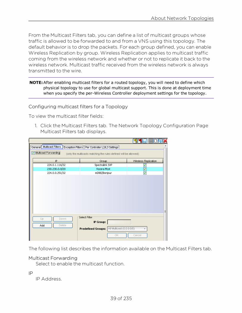
39 of 235
From the Multicast Filters tab, you can define a list of multicast groups whosetraffic is allowed to be forwarded to and from a VNS using this topology. Thedefault behavior is to drop the packets. For each group defined, you can enableWireless Replication by group. Wireless Replication applies to multicast trafficcoming from the wireless network and whether or not to replicate it back to thewireless network. Multicast traffic received from the wireless network is alwaystransmitted to the wire.
NOTE:After enabling multicast filters for a routed topology, you will need to define whichphysical topology to use for global multicast support. This is done at deployment timewhen you specify the per-Wireless Controller deployment settings for the topology.
Configuring multicast filters for a Topology
To view the multicast filter fields:
1. Click the Multicast Filters tab. The Network Topology Configuration PageMulticast Filters tab displays.
The following list describes the information available on the Multicast Filters tab.
Multicast ForwardingSelect to enable the multicast function.
IPIP Address.

About Network Topologies
40 of 235
GroupMulticast group.
Wireless ReplicationTo enable the wireless multicast replication for this group, select the WirelessReplication checkbox.
Up | Down | Add | DeleteSelect a filter from the Predefined Groups drop-down menu:
Click Add to add a predefined filter.
Click Delete to remove a predefined filter.
Click Up to raise the priority of the selected multicast group.
Click Down to lower the priority of the selected multicast group.
Select FilterIP Group
The IP range for multicast groups.
Predefined GroupsSelect from the list of predefined multicast group (includes User Defined).
OKClick to save the configuration.
CancelClick to discard the changes to the configuration.
To configure multicast filters for a topology:
1. Select Multicast Forwarding to enable the multicast function.
2. Define the multicast groups by using the following controls:
l IP Group – Type the IP address range.
l Predefined groups – Click from the drop-down list
3. Click Add. The group is added to the list above.
4. To enable the wireless multicast replication for this group, select thecorresponding Wireless Replication checkbox.
5. To modify the priority of the multicast groups, click the group row, andthen click the Up or Down buttons. Only the multicast traffic matching therules defined on the page will be allowed.
6. To save your changes, click Save.
About Network Topologies
41 of 235
Exception Filters
CAUTION: If defined improperly, user exception rules may seriously compromise thesystem’s normal security enforcement rules. They may also disrupt the system'snormal operation and even prevent system functionality altogether. It is advisedto only augment the exception-filtering mechanism if absolutely necessary.
For bridged at Wireless Controller topologies, you can define exception filtersonly if L3 (IP) interfaces are specified. For routed topologies, exception filteringis always configured since they all have an L3 interface presence.
On the Wireless Controller, various interface-based exception filters are built inand invoked automatically. These filters protect the Wireless Controller fromunauthorized access to system management functions and services via theinterfaces. Access to system management functions is granted if theadministrator selects the allow management traffic option in a specific topology.
Allow management traffic is possible on the topologies that have L3 IP interfacedefinitions when the topology configuration has allow management trafficenabled. Users will only be able to target the topology interface specifically.
On the L3 interfaces (associated with either routed, or bridged locally atWireless Controller topologies), the built-in exception filter prohibits invokingSSH, HTTPS, or SNMP. However, such traffic is allowed, by default, on themanagement port.
If management traffic is explicitly enabled for any interface, access is implicitlyextended to that interface through any of the other interfaces (VNS). Only trafficspecifically allowed by the interface’s exception filter is allowed to reach theWireless Controller itself. All other traffic is dropped. Exception filters aredynamically configured and regenerated whenever the system's interfacetopology changes (for example, a change of IP address for any interface).
Enabling management traffic on an interface adds additional rules to theexception filter, which opens up the well-known IP (TCP/UDP) ports,corresponding to the HTTPS, SSH, and SNMP applications.
The interface-based built-in exception filtering rules, in the case of traffic fromwireless users, are applicable to traffic targeted directly for the topology L3interface. Exception filter rules are evaluated after the user's assigned filterpolicy, as such, it is possible that the policy allows the access to managementfunctions that the exception filter denies. These packets are dropped.
To enable SSH, HTTPS, or SNMP access through a physical data interface:

About Network Topologies
42 of 235
1. Navigate to the details page of a specific Bridged at EWC or routedtopology.
2. Click the Exception Filters tab. If your topology type is Bridged at EWC,you will have to first select the Layer 3 Presence checkbox. The ExceptionFilters tab is displayed.
3. Select the Management Traffic checkbox if the topology has specified anL3 IP interface presence.
4. To save your changes, click Save.
You can add specific filtering rules at the interface level in addition to the built-inrules. Such rules give you the capability of restricting access to a port, forspecific reasons, such as a Denial of Service (DoS) attack.
The filtering rules are set up in the same manner as filtering rules defined for aPolicy — specify an IP address, select a protocol if applicable, and then eitherallow or deny traffic to that address.
The rules defined for port exception filters are prepended to the normal set ofrestrictive exception filters and have precedence over the system's normalprotection enforcement (that is, they are evaluated first).
To define interface exception filters:
1. Click the Configured Objects tab.
2. In the left pane, click Network Topologies. The Network Topologies screenis displayed.
3. Select a topology to be configured. The Edit Topology window isdisplayed.
4. Select the Exception Filters tab. The Exception Filter page displays.
NOTE:The Exception Filters tab is available only if you defined an L3 interface for thetopology

About Network Topologies
43 of 235
The following list describes the information available on the Exception Filterstab.
RuleIdentifies the type of filter rule. Options Include: D - Default rule, and U - user-defined rule.
InIdentifies how to filter traffic coming into the network from the wirelessstations. Check the rule's checkbox in this column to have the rule applied.The list includes: Destination (dest), Source (src), None, and Both.
AllowCheck the rule's checkbox in this column to cause traffic matching this rule tobe forwarded. Clear the checkbox in this column to have the rule deny trafficthat matches the rule.
IP: PortIP address, or address and optionally port or port range to which this ruleapplies.
ProtocolThe particular protocol to which this rule applies.
Up | Down | Add | DeleteClick Add to specify the details of the filter rule to be added.
About Network Topologies
44 of 235
Click Delete to remove the selected filter rule.
Click Up to raise the priority of the selected filter rule.
Click Down to lower the priority of the selected filter rule.
IP/SubnetThe IP address to filter on. You can also specify an IP range, a portdesignation, or a port range on that IP address.
PortSpecifies a port designation, or a port range on the IP address.
ProtocolClick the protocol you want to specify for the filter. This list may include UDP,TCP, GRE, IPsec-ESP, IPsec-AH, User Defined, and ICMP. The default is N/A.
In FilterClick an option that refers to how to filter traffic coming into the networkfrom wireless stations. This list includes: Destination (dest), Source (src),None, and Both. The default is None.
OKClick to save changes.
CancelClick to discard changes.
To configure exception filters:
1. Click the Add button. The Filter Editor dialog appears in a separatewindow.
2. Fill in the following fields:
In the IP/subnet box, type the destination IP address. Using the Port dropdown, you can also specify a User Defined or well-known port to filter onfor the specified IP. You can also specify an IP range, a port designation, ora port range on that IP address.
In the Protocol drop-down list, click the protocol you want to specify forthe filter. This list may include UDP, TCP, GRE, IPsec-ESP, IPsec-AH, ICMP,User Defined, and N/A. The default is N/A.
In the In Filter field, select a mode for filtering traffic going inbound from

About Network Topologies
45 of 235
the Mobile Unit (MU) into the network. Options include Destination, Source,None, and Both.
3. The new filter displays Exception Filters page.
4. Click the new filter entry.
5. To allow traffic, select the Allow checkbox.
6. To adjust the order of the filtering rules, click Up or Down to position therule. The filtering rules are executed in the order defined here.
7. To save your changes, click Save
Per Controller L2/L3 Settings
Per Controller settings are read-only in the template. To change them, you mustcreate a task to redeploy the template with the new settings.
To view the Per Controller L2/L3 Settings:
1. Click the Configured Objects tab.
2. In the left pane, click Network Topologies. The Network Topologies pagedisplays.
3. Select a topology. The Edit Topology page displays.
4. Select the Per Controller L2/L3 Settings tab. The Per Controller L2/L3Settings page displays.

About Network Topologies
46 of 235
The following list describes the information available on the Per Controller L2/L3Settings tab.
ControllerWireless Controller to which the group of settings in the table row applies.
GatewayThe Wireless Controller's IP address on the topology (VLAN).
MaskMask - The subnet mask that applies to traffic on the topology (VLAN) at theWireless Controller.
DHCPSpecifies whether DHCP is enabled on the EWC for this topology and if so,whether DHCP relay or DHCP server mode is in effect.
View DHCP SettingsClick to view DHCP settings.
ModeIf the DHCP mode is "DHCP relay" then this attribute will be displayed. It isthe IP address of the DHCP server to which the DHCP relay will forwardDHCP traffic.
Domain NameThe domain name that DHCP clients should use.
Lease (seconds) defaultThe time period for which the IP address will be allocated to any devicerequesting it.
Lease (seconds) maxThe maximum time period in seconds for which the IP address will beallocated to any device.
DNS ServersIP address of DNS servers. This list will be sent to DHCP clients along with anIP address.
WINSIP address of WINS servers. This list will be sent to DHCP clients along withan IP address.

About Network Topologies
47 of 235
DLS AddressThe address of a maintenance server. This setting is sent to SiemensEnterprise WL2 phones. To provide the address of the DLS server, first checkthe "Enable DLS DHCP option" checkbox, then supply an address in the DLSaddress field.
Next Hop AddressThe IP address of the next hop router on the network through which you wishall traffic on the VNS using this Topology to be directed.
OSPF Route CostEnter the OSPF cost of reaching the VNS subnet. This value provides arelative cost indication to allow upstream routers to calculate whether or notto use the Wireless Controller as a better fit or lowest cost path to reachdevices in the network.
Address RangeThe first and last address in the range of addresses that the DHCP server cangive out for this topology.
ExclusionsClick this button to be able to specify one or more ranges within the overalladdress range that should not be given out.
B'cast AddressThis field populates automatically based on the IP address and subnet maskof the VNS.
Toolbar ButtonsFor a description of common toolbar buttons see Context-Sensitive Toolbar.
NOTE:It will only be possible to delete a topology if it is not in use by Policy Manager orreferenced by another template.
Viewing Topology Summary InformationYou can view summary information for all topologies discovered on WirelessControllers or created in Wireless Manager. This information is available from theTopologies Summary page. You can display this information by topology nameor topology type.
From the Topology Summary page, you can also perform the following tasks:

About Network Topologies
48 of 235
l Retrieve the list of topologies associated with all managed WirelessControllers.
l Deploy or undeploy the topology.
l Edit or clone an existing topology.
l Export the configuration to the Wireless Controller’s CLI.
l Create a new topology.
l Delete an existing topology.
To view the Topologies Summary page:
1. Click the Configured Objects tab.
2. In left-hand pane, click Network Topologies. The Network TopologiesSummary page displays.
The following list describes the information available on the Network TopologiesSummary Page.
StatusStatus of this Network Topology. Options include:
Deployed, Not Deployed, Deployed but not synchronized to thenetwork

About Network Topologies
49 of 235
Topology NameA string of alphanumeric characters used to identify the topology.
GroupIndicates whether the topology is part of a topology group. Options include:
Included in a topology group, Not included in a topology group
VIDThe VLAN identifier as specified in the IEEE 802.1Q definition.
TaggedIndicates whether the VLAN is tagged or untagged.
TypeIndicates the type of topology. Options include:
Routed
B@AP (Bridged @ AP)
B@HWC (Bridged @ Controller)
No. ControllersNumber of Wireless Controllers using this topology.
ControllersFor topologies corresponding to PM VLANs, 'Controllers' lists by IP addressthose controllers in the PM domain. For topologies which have no VLANcounterpart in PM, 'Controllers' lists by IP address those controllers to whichthe topology has been deployed.
Toolbar ButtonsFor a description of common toolbar buttons see Context-Sensitive Toolbar.
NOTE:It will only be possible to delete a topology if it is not in use by Policy Manager orreferenced by another template.
Editing a TopologyYou can edit a topology at any time. Any changes that you make to a topologyconfiguration do not take effect until you create a task to deploy the modifiedtopology.
To edit a topology:

About Network Topologies
50 of 235
1. Click the Configured Objects tab.
2. In left-hand pane, click Network Topologies. The Network TopologiesSummary page displays.
3. Select a topology on the Topologies Summary page and either click theedit icon at the top of the page or right-click on the task name and selectEdit from the drop-down menu. The Topologies Summary page displays.
Deleting a TopologyYou can delete a topology only if it is not currently being used or referenced by arole, WLAN, or topology group. Deleting a topology group deletes only thattopology group, not the topologies it contains.
To delete a topology:
1. Click the Configured Objects tab.
2. In left-hand pane, click Network Topologies. The Network TopologiesSummary page displays.
3. Select a topology from the list on the Topologies Summary page.
4. Click the Delete icon. Wireless Manager prompts to verify that you want todelete the selected topology.
5. Click OK to continue or Cancel to abort the topology deletion.

51 of 235
About Wireless Networks
Using the Wireless Networks tab in Wireless Manager, you can view informationabout elements of your wireless network, including Wireless Controllers, MobilityZones, and shared secrets.
This Help topic includes the following information:
l Shared Secrets Page
l Viewing Mobility Zone Summary Information
l Viewing Mobility Zone Details
l Viewing Controller Summary Information
l Viewing Controller Details
l Adaptive Management UI
l Browser Certificate Warnings
l Accessing the Dashboard Page
l Accessing the Logs Page
l Accessing the Wireless Controller Configuration Page
l Accessing the Wireless APs Page
l Accessing the VNS Configuration Page
Shared Secrets PageWireless Manager relies on shared secrets for authentication with WirelessControllers. From the Generate Shared Secrets page, you can set the sharedsecret used to authenticate Wireless Manager to a Wireless Controller and youcan change that shared secret manually or by generating a random sharedsecret.
You can view the shared secret for each Wireless Controller from the WirelessController summary page and from the Wireless Controller configuration page.
To set the shared secret used with a Wireless Controller:
1. Click the Configured Objects tab.
2. In left-hand pane, click Wireless Networks > Generated Shared Secrets. TheGenerate Shared Secret page displays.

About Wireless Networks
52 of 235
The following list describes the information available on the Generate SharedSecret page.
GenerateClick to generate a random shared secret. The shared secret displays in theempty field.
Controller NameThe name or IP address of the Wireless Controller.
SetClick to assign the generated shared secret to the corresponding WirelessController.
Viewing Mobility Zone Summary InformationA Mobility Zone is a set of Wireless Controllers organized in a logical pattern sothat a mobile user can seamlessly roam between the APs of different WirelessControllers in the set. A Mobility Zone can only be configured from the WirelessController (for more information, refer to the Extreme Networks WirelessConvergence Software User Guide for details on setting up a Mobility Zone). AMobility Zone may contain up to 12 controllers; one controller in the group isdesignated as the mobility manager, and all others are designated as mobilityagents.
The controller designated as the mobility manager:

About Wireless Networks
53 of 235
l Is explicitly identified as the manager for a specific mobility domain. Agentswill connect to this manager to establish a mobility domain.
l Defines the registration behavior for a multi-controller mobility domain.
l Listens for connection attempts from mobility agents.
l Establishes connections and sends a message to the mobility agentspecifying the heartbeat interval, and the mobility manager's IP address if itreceives a connection attempt from the agent.
l Sends regular heartbeat messages containing wireless device sessionchanges and agent changes to the mobility agents and waits for a returnedupdate message.
l Establishes a connection to an optional backup mobility manager that canbe configured to back up the primary mobility manager.
A controller designated as a mobility agent:
l Uses SLP or a statically configured IP address to locate the mobilitymanager.
l Defines at the agent, the IP address of the mobility manager, which allowsfor the bypass of SLP. Agents directly find and attempt to register with themobility manager.
l Attempts to establish a TCP/IP connection with the mobility manager.
l Connects to an optional backup mobility manager that can be configuredto back up the primary mobility manager.
l Sends updates, in response to the heartbeat message, on the wirelessdevice users and the data tunnels to the mobility manager.
If the connection to a controller configured as the mobility manager is lost, with abackup mobility manager configured, the following occurs:
l If enabled, the controller establishes a connection to the optional backupmobility manager. When a failure occurs, the backup manager becomesthe primary manager and control tunnels are re-negotiated. The datatunnels are not affected. When the primary manager comes back online,the backup manager detects the higher priority manager and switchesback to agent (passive) mode.
If the connection to a controller configured as the mobility manager is lost,without a backup mobility manager, the following occurs:

About Wireless Networks
54 of 235
l Agent-to-agent connections remain active.
l The mobility agents continue to operate based on the mobility informationlast coordinated before the manager link was lost. The mobility location listremains relatively unaffected by the controller failure. Only entriesassociated with the failed controller are cleared from the registration list,and users that have roamed from the manager controller to other agentsare terminated and required to re-register as local users with the agentwhere they are currently located.
l The data link between active controllers remains active after the loss of amobility manager.
l Mobility agents continue to use the last set of mobility location lists toservice known users.
l Existing users remain in the mobility scenario, and if the users are known tothe mobility domain, they continue to be able to roam between connectedcontrollers.
l New users become local at attaching controller.
l Roaming to another controller resets session.
In Wireless Manager, a Mobility Zone is created when a Wireless Controller that isthe manager for a Mobility Zone is managed by NetSight. The Mobility Zone ismaintained until that Wireless Controller is unmanaged.
To view the Wireless Controllers assigned to each Mobility Zone:
1. Click the Configured Objects tab.
2. In left-hand pane, click Wireless Networks > Mobility Zones. The MobilityZones page displays.

About Wireless Networks
55 of 235
The following list describes the information available on the Mobility ZonesSummary page.
NameMobility Zones are named according to the IP address of their ManagerWireless Controller.
ManagerIP address of the manager of the Mobility Zone.
Backup ManagerIP Address of the VN backup manager. In the event that the primary VNmanager crashes, the backup VN manager takes over responsibility for 1)distributing MU sessions to the other VN agents in the mobility domain, and2) helping to setup data & controller tunnels in the mobility domain. Only onemanager is active at a time, the other works as a normal VN agent in PASSIVEmode. When both the primary and backup managers are active, the primarymanager will assume the role of VN manager.
No. AgentsNumber of agents that are part of this Mobility Zone.
AgentsList of IP addresses of the Mobility Zone agent Wireless Controllers. Theagent configured as the backup manager will be displayed with a "(BM)"next to its display name.

About Wireless Networks
56 of 235
Viewing Mobility Zone DetailsTo view detailed information about a particular Mobility Zone:
1. Click the Configured Objects tab.
2. In left-hand pane, click Wireless Networks > Mobility Zones. The MobilityZones Summary page displays.
3. Click on a Mobility Zone in the list. The Mobility Zones Details pagedisplays.
The following list describes the information available on the Mobility ZonesDetails page.
ManagerIP address of the manager of the Mobility Zone.
Mgmt MAC AddressMAC address of the selected manager Wireless Controller.
VersionThe software version running on the manager Wireless Controller.
AgentList of IP addresses of the Mobility Zone agent Wireless Controllers.
Mgmt MAC AddressMAC address of the selected agent Wireless Controller.

About Wireless Networks
57 of 235
VersionThe software version running on the selected agent Wireless Controller.
Viewing Controller Summary InformationYou can view summary information about all Wireless Controllers known toWireless Manager from the Wireless Controllers Summary page. From this page,you can also:
l Connect to the ExtremeWireless Wireless Assistant to modify WirelessController settings.
l Connect to Management Center to view reports and statistics.
l Select a Wireless Controller and click the edit icon to view the collectedWireless Controller details and to edit the Wireless Controller's sharedsecret.
To view Wireless Controller summary information:
1. Click the Configured Objects tab.
2. In left-hand pane, click Wireless Networks > Controllers. The WirelessControllers Summary page displays.
The following list describes the information available on the ControllersSummary page.
IP AddressIP address assigned to the selected Wireless Controller.
Host NameName assigned to the selected Wireless Controller.

About Wireless Networks
58 of 235
Mgmt MAC AddressMAC address of the selected Wireless Controller.
VersionThe software version running on the selected Wireless Controller.
Shared SecretShared secret used for communication between the Wireless Controller andWireless Manager.
Sync StatusSynchronization status which identifies whether Wireless Manager was ableto read relevant configuration data from the Wireless Controller.
AP NameNames of the APs associated with the selected Wireless Controller.
AP RoleRole of the AP in the network.
LocationLocation of the AP. Options include Foreign or Local.
StatusApproval status of the AP.
ActiveCurrent activity status of the AP. Options include Active or Inactive.
IP AddressIP address assigned to the selected AP.
MAC AddressMAC address of the selected AP.
Hardware TypeHardware model of the selected AP.
Toolbar ButtonsFor a description of common toolbar buttons see Context-Sensitive Toolbar.
Viewing Controller DetailsTo view detailed information about a particular Wireless Controller:
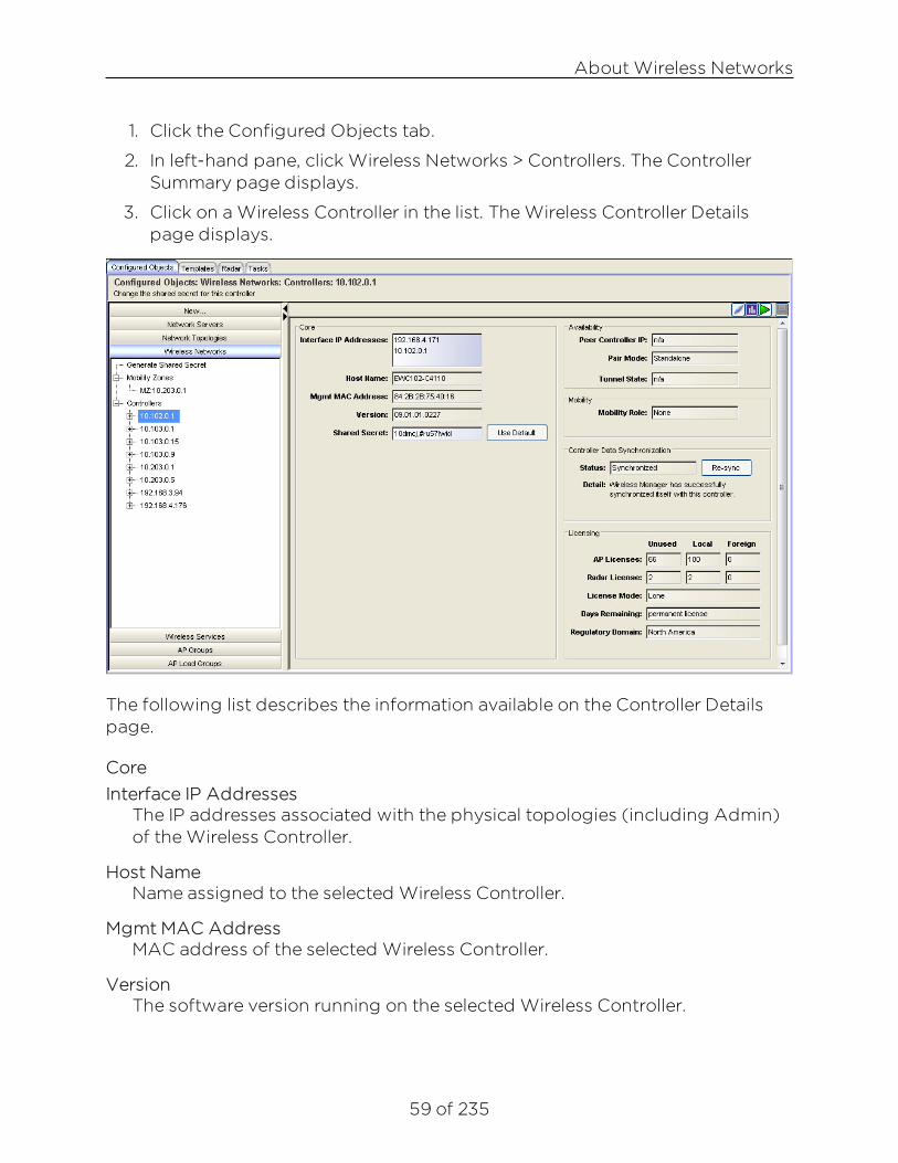
About Wireless Networks
59 of 235
1. Click the Configured Objects tab.
2. In left-hand pane, click Wireless Networks > Controllers. The ControllerSummary page displays.
3. Click on a Wireless Controller in the list. The Wireless Controller Detailspage displays.
The following list describes the information available on the Controller Detailspage.
CoreInterface IP Addresses
The IP addresses associated with the physical topologies (including Admin)of the Wireless Controller.
Host NameName assigned to the selected Wireless Controller.
Mgmt MAC AddressMAC address of the selected Wireless Controller.
VersionThe software version running on the selected Wireless Controller.

About Wireless Networks
60 of 235
Shared SecretShared secret used for communication between the Wireless Controller andWireless Manager.
AvailabilityPeer Controller IP
MAC address of the selected Wireless Controller. If the Wireless Controller isa part of an availability peer, this is the availability peer’s IP address.
Pair ModeIdentifies whether the Wireless Controller is part of an availability pair or is astandalone Wireless Controller.
Tunnel StateDisplays the state of the data tunnel between Wireless Controllers.
MobilityMobility Role
Role that the Wireless Controller takes in a Mobility Zone. Options include:Agent or Manager.
Controller Data SynchronizationStatus
Status that identifies whether Wireless Manager is able to read relevantconfiguration information from the Wireless Controller. Possible values are:
Not synchronized - Wireless Manager cannot read relevant configurationdata from the Wireless Controller.
Synchronized - Wireless Manager can read relevant configuration data fromthe Wireless Controller.
DetailAn informational message that identifies the reason why the status is NotSynchronized.
LicensingAP Licenses
Displays the following AP license information:
Unused AP Licenses: Total number of unassigned AP licenses.
Local AP Licenses: Total number of AP licenses local to this controller.

About Wireless Networks
61 of 235
Foreign AP Licenses: Total number of AP licenses local to this controller'savailability partner.
Radar LicensesDisplays the following Radar license information:
Unused Radar Licenses: Total number of unassigned Radar licenses.
Local Radar Licenses: Total number of Radar licenses local to this controller.
Foreign Radar Licenses: Total number of Radar licenses local to thiscontroller's availability partner.
A Radar capacity license is required for APs assigned to In-Service andGuardian scan profiles. Each assigned AP counts as one against the licensedRadar capacity.
If the number of APs licensed for Radar is zero, you can create a scan profilewithout assigned APs, update a scan profile but only remove assigned APs,or delete a scan profile.
License ModeDisplays the license mode for the selected controller. A controller can operatein either Lone or Paired mode.
Lone (standalone) - Only local APs are counted against locally installed APcapacity keys. All Radar In-Service and Guardian APs are counted againstlocally installed Radar keys. This is the default license mode. A controllerswitches to Paired mode when Availability is enabled.
Paired - Both local and foreign APs are counted against the sum of locallyinstalled AP capacity keys and AP capacity keys pooled from the peercontroller. All Radar In-Service and Guardian APs are counted against thesum of Radar keys installed locally and on the peer controller. A controllerswitches to Lone (standalone) mode if Availability is disabled.
Days RemainingDisplays the number of days remaining on this license key. When anevaluation license or grace period (for installing the appropriate major releasekey) expires, all Radar functions stop until a permanent license is installed.
Regulatory DomainDisplays the regulatory domain for which the controller is licensed.
Toolbar ButtonsFor a description of common toolbar buttons see Context-Sensitive Toolbar.

About Wireless Networks
62 of 235
Adaptive Management UIYou can view configuration and summary information about a specific WirelessController, running V8.11 or later, using the Adaptive Management User Interface(UI). Once synchronized, Wireless Manager retrieves Wireless Controllermanagement UI data and displays the menu hierarchy under ConfiguredObjects > Wireless Networks > Controllers > specific Wireless Controller.
The adaptive management menu is intended to allow Wireless Manager to beable to easily configure all aspects of 8.11+ Wireless Controllers. WirelessManager can also support the configuration of a Wireless Controller runningsoftware released after Wireless Manager was released, by retrieving itsmanagement menu each time the controller transitions to Synchronized.
Although the adaptive management menu may be different for differentWireless Controller versions, in general, its structure mirrors the menu hierarchyof the Wireless Controller that reported it, except for those menu items whichrefer to features of the Wireless Controller which are already configurable byWireless Manager. For example, Wireless Manager purposefully excludes thefollowing menu items under VNS Configuration, from each Wireless Controller'sadaptive management menu: Global > Bandwidth Control, Virtual Networks,WLAN Services, Policies, Class of Services, and Topologies.
Clicking a menu item launches the default browser which displays thecorresponding controller page (in either a new window or new tab). Thisbrowser window simplifies your navigation within and between the pages of thevarious controller GUIs, by including on the left-hand side of the page alldiscovered controllers and their adaptive management menus. The menus areidentical to those displayed in Wireless Manager's Configured Objects >Wireless Networks > Controllers submenu, except that clicking a menu itemopens the corresponding controller page on the right-hand side withoutopening a new browser window.
The adaptive management feature is only available to users with WirelessManager Configure capability.
The following top-level Wireless Controller pages are accessible using theAdaptive Management UI:
l Dashboard
l Logs
l Wireless Controller

About Wireless Networks
63 of 235
l Wireless APs
l VNS Configuration
Browser Certificate Warnings
Certificate related warnings may appear when clicking links in the adaptivemanagement menu for a Wireless Controller. Instructions provide steps on howto handle each warning based on the following types (and versions) ofbrowsers:
l Chrome
l Firefox
l Internet Explorer
Chrome
1. Click the Configured Objects tab.
2. In left-hand pane, click Wireless Networks > Controllers, select a WirelessController, and click the Connect button . The following error messagedisplays on a blank page.
3. Click the Fix button. A dialog box appears informing you a new windowwill open.

About Wireless Networks
64 of 235
4. Click OK.
5. Click Proceed to IP (unsafe) when the following window is displayed.
6. Go to Accessing the Dashboard Page.
Firefox
1. Click the Configured Objects tab.
2. In left-hand pane, click Wireless Networks > Controllers, select a WirelessController, and click the Connect button . The following error messagedisplays.

About Wireless Networks
65 of 235
3. Right-click the error message, and select This Frame -> Show Only ThisFrame.
4. On the Untrusted dialog, click Add Exception.

About Wireless Networks
66 of 235
5. On the Add Security Exception dialog, click Confirm Security Exception.

About Wireless Networks
67 of 235
6. Click back.
7. Go to Accessing the Dashboard Page.
Internet Explorer
1. Click the Configured Objects tab.
2. In left-hand pane, click Wireless Networks > Controllers, select a WirelessController, and click the Connect button . The following error messagedisplays.
3. Click Show content at the bottom of the dialog.
4. Go to Accessing the Dashboard Page .
Accessing the Dashboard Page
The Dashboard page (Wireless Assistant Home screen) provides real-timestatus information on the current state of the wireless network. Information isgrouped under multiple functional areas (network status, admin sessions, and soon) and provides a graphical representation of active AP information (such asthe number of wired packets, stations, and total APs).
To access the Dashboard page:
1. Click the Configured Objects tab.
2. In left-hand pane, click Wireless Networks > Controllers, and select aWireless Controller. The tree node expands and displays the WirelessController menus.

About Wireless Networks
68 of 235
3. In the left-hand pane, click Dashboard > Home. The Wireless AssistantHome page displays.
Accessing the Logs Page
The Wireless Assistant - Logs & Traces page contains messages that include thetime of event, severity, source component, and any details generated by thesource component. Log messages are divided into three groups: controller logs,wireless AP logs, and login logs.
To access the Logs & Traces page:
1. Click the Configured Objects tab.
2. In left-hand pane, click Wireless Networks > Controllers, and select aWireless Controller. The tree node expands and displays the WirelessController menus.
3. In the left-hand pane, click Logs. The Wireless Assistant Logs & Tracespage displays.

About Wireless Networks
69 of 235
Accessing the Wireless Controller Configuration Page
The Wireless Assistant - Wireless Controller Configuration page include a seriesof configuration tasks. These tasks include:
l Changing the administrator password
l Applying product license keys
l Setting up the data ports
l Setting up static routes
To access the Wireless Controller Configuration page:
1. Click the Configured Objects tab.
2. In left-hand pane, click Wireless Networks > Controllers, and select aWireless Controller. The tree node expands and displays the WirelessController menus.
3. In the left-hand pane, click Wireless Controller. The Wireless ControllerConfiguration page displays.

About Wireless Networks
70 of 235
Accessing the Wireless APs Page
The Wireless Assistant - Wireless APs page includes menus that includeinformation on how to install the wireless AP, how it discovers and registers withthe Wireless Controller, and how to view and modify radio configuration.
To access the Wireless APs page:
1. Click the Configured Objects tab.
2. In left-hand pane, click Wireless Networks > Controllers, and select aWireless Controller. The tree node expands and displays the WirelessController menus.
3. In the left-hand pane, click Wireless APs. The Wireless APs page displays.

About Wireless Networks
71 of 235
IMPORTANT: NetSight version 7.0 supports up to 7,500 APs and 50,000 clients across allmanaged wireless controllers. For sites with more than the supportednumber of APs and clients, contact your sales representative to acquire anadditional NetSight license.
Accessing the VNS Configuration Page
The Wireless Assistant - VNS Network Configuration page includes menus thatprovide detailed information on how to configure a VNS, either using thewizards or by manually creating the component parts of a VNS.
To access the VNS Network Configuration page:
1. Click the Configured Objects tab.
2. In left-hand pane, click Wireless Networks > Controllers, and select aWireless Controller. The tree node expands and displays the WirelessController menus.
3. In the left-hand pane, click VNS Configuration. The Virtual NetworkConfiguration page displays.

About Wireless Networks
72 of 235
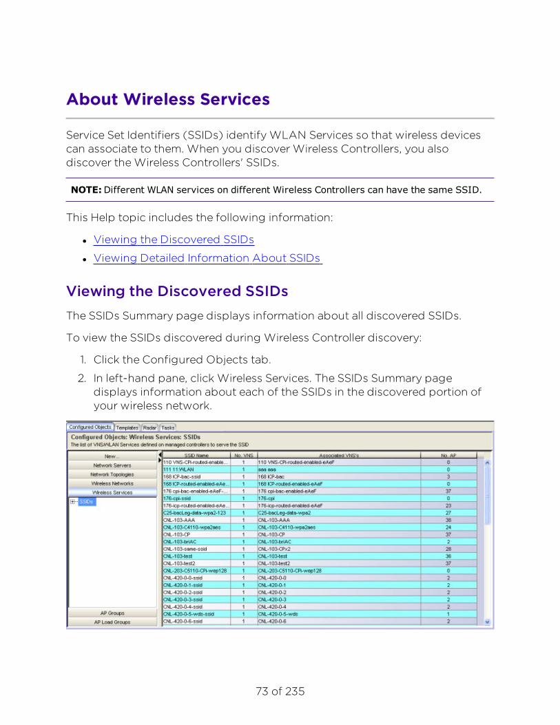
73 of 235
About Wireless Services
Service Set Identifiers (SSIDs) identify WLAN Services so that wireless devicescan associate to them. When you discover Wireless Controllers, you alsodiscover the Wireless Controllers' SSIDs.
NOTE:Different WLAN services on different Wireless Controllers can have the same SSID.
This Help topic includes the following information:
l Viewing the Discovered SSIDs
l Viewing Detailed Information About SSIDs
Viewing the Discovered SSIDsThe SSIDs Summary page displays information about all discovered SSIDs.
To view the SSIDs discovered during Wireless Controller discovery:
1. Click the Configured Objects tab.
2. In left-hand pane, click Wireless Services. The SSIDs Summary pagedisplays information about each of the SSIDs in the discovered portion ofyour wireless network.

About Wireless Services
74 of 235
The following list describes the information available on the SSIDs Summarypage.
SSID NameThe SSID that identifies the service for wireless devices.
No. VNSNumber of different VNSs identified by this SSID.
Associated VNS’sNames of the VNS's associated with this SSID.
No. APThe number of APs advertising this SSID.
Viewing Detailed Information About SSIDsThe SSID Details page displays detailed information about a selected SSID.
To view detailed information about a selected SSID:
1. Click the Configured Objects tab.
2. In the left-hand pane, click Wireless Services. The SSIDs Summary pagedisplays.
3. Select an SSID from the list. The SSIDs Details page displays. To determinewhich APs are serving the SSID for a specific VNS, select the VNS on theleft side of the table.
The following list describes the information available on the SSIDs Details page.

About Wireless Services
75 of 235
VNS NameName of the VNS associated with the SSID.
No. APsNumber of APs associated with the Wireless Controller.
ControllerIP address of the Wireless Controller hosting the VNS.
AP NameNames of the APs advertising the SSID on behalf of the selected VNS.
IP AddressIP address of the AP.
LocationAP location. Options are: Local or Foreign.
StatusConnection status of AP (Active or Inactive).
Radio 1Radio 1 configuration setting.
Radio 2Radio 2 configuration setting.

76 of 235
About AP Groups
An AP Group is a named collection of APs. The APs in the AP Group can belongto different Wireless Controllers. You can use an AP Group as you would anindividual AP so that you can apply the same configuration settings to multipleAPs at the same time.
Wireless Manager automatically creates a Default AP Group for each managedWireless Controller. This Default AP Group contains all of the APs that havebeen approved as local APs and that have been reported as active on theWireless Controller at least once. This per-controller Default AP Group includesall APs associated with the specified Wireless Controller.
You can also create additional AP Groups called Custom AP Groups. Any APknown to Wireless Manager can be added to any Custom AP Group and anindividual AP can be included in more than one AP Group.
This Help topic includes the following information:
l Viewing a List of AP Groups
l Viewing AP Groups Details
l Creating an AP Group
l Editing an AP Group
l Deleting an AP Group
Viewing a List of AP GroupsTo view a list of AP Groups configured in Wireless Manager:
1. Click the Configured Objects tab.
2. In left-hand pane, click AP Groups.
3. The AP Groups Summary page displays. The page lists characteristicsabout all defined AP Groups. To create a new AP Group, refer to Creatingan AP Group. To change an existing AP Group, refer to Editing an APGroup.

About AP Groups
77 of 235
The following list describes the information available on the AP GroupsSummary page.
NameName assigned to the AP Group.
No. of APsNumber of APs assigned to the AP Group.
TypeIdentifies whether the AP Group is a Default AP Group or a user-createdCustom AP Group.
ControllersNames of the Wireless Controllers associated with the APs included in the APGroup.
Toolbar ButtonsFor a description of common toolbar buttons see Context-Sensitive Toolbar.
Viewing AP Groups DetailsTo view detailed information about a particular AP Group:
1. Click the Configured Objects tab.
2. In left-hand pane, click AP Groups. The AP Groups Summary pagedisplays.
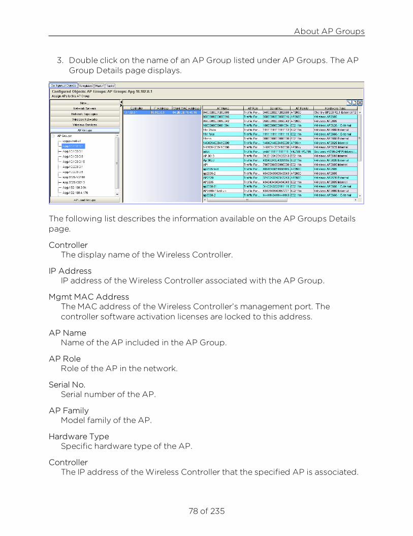
About AP Groups
78 of 235
3. Double click on the name of an AP Group listed under AP Groups. The APGroup Details page displays.
The following list describes the information available on the AP Groups Detailspage.
ControllerThe display name of the Wireless Controller.
IP AddressIP address of the Wireless Controller associated with the AP Group.
Mgmt MAC AddressThe MAC address of the Wireless Controller’s management port. Thecontroller software activation licenses are locked to this address.
AP NameName of the AP included in the AP Group.
AP RoleRole of the AP in the network.
Serial No.Serial number of the AP.
AP FamilyModel family of the AP.
Hardware TypeSpecific hardware type of the AP.
ControllerThe IP address of the Wireless Controller that the specified AP is associated.

About AP Groups
79 of 235
StatusApproval status of the AP.
Toolbar ButtonsFor a description of common toolbar buttons see Context-Sensitive Toolbar.
Creating an AP GroupTo create an AP Group, you must select APs from the list of all controller-managed APs known to Wireless Manager. After you create the AP Group,Wireless Manager generates an audit record that shows the name of the APGroup, the user ID of the account that created the AP Group, and the date andtime when it created the AP Group.
To create an AP Group:
1. Click the Configured Objects tab.
2. In left-hand pane, click AP Groups. The AP Groups Summary pagedisplays.
3. Click on the New icon in the tool bar. The Create New AP Group pagedisplays.
4. In the AP Group Name field, enter the name of the new AP Group.
5. In the WLAN Controller field, click on a controller name. When you select acontroller, the list of APs associated with that controller populate theAvailable APs window.

About AP Groups
80 of 235
6. To include an AP in the named AP Group, select an AP from the AvailableAPs window and use the right arrow key to move it into the APs in Groupwindow. To remove an AP from the named AP Group, select an AP in theAPs in Group window and use the left arrow key to move it into theAvailable APs window.
7. To create an AP Group that contains APs from multiple WirelessControllers, select another controller from the WLAN Controller list andrepeat steps 5 and 6.
8. Click OK to save the new AP Group or click Cancel to discard the AP Groupconfiguration.
You can also access the Create New AP Group page from the ConfiguredObjects tab by clicking New > AP Group or from the AP Group Summary pageby right-clicking on a controller name and selecting the New icon.
Editing an AP GroupYou can edit only user-created Custom AP Groups; you cannot edit Default APGroups.
To edit a Custom AP Group configuration:
1. Click the Configured Objects tab.
2. In left-hand pane, click AP Groups. The AP Groups Summary pagedisplays.
3. Select an AP Group from the list on the AP Groups Summary page.
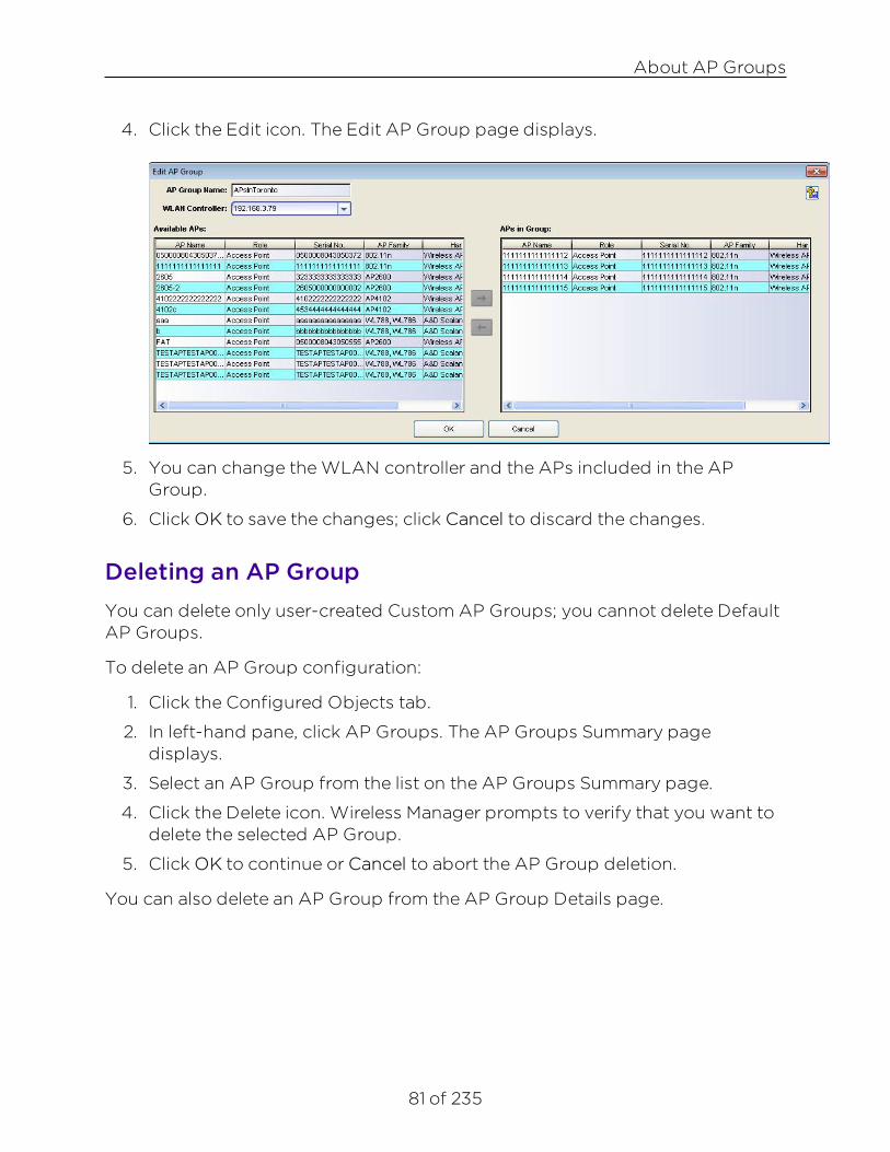
About AP Groups
81 of 235
4. Click the Edit icon. The Edit AP Group page displays.
5. You can change the WLAN controller and the APs included in the APGroup.
6. Click OK to save the changes; click Cancel to discard the changes.
Deleting an AP GroupYou can delete only user-created Custom AP Groups; you cannot delete DefaultAP Groups.
To delete an AP Group configuration:
1. Click the Configured Objects tab.
2. In left-hand pane, click AP Groups. The AP Groups Summary pagedisplays.
3. Select an AP Group from the list on the AP Groups Summary page.
4. Click the Delete icon. Wireless Manager prompts to verify that you want todelete the selected AP Group.
5. Click OK to continue or Cancel to abort the AP Group deletion.
You can also delete an AP Group from the AP Group Details page.

82 of 235
About AP Load Groups
An AP Load Group is defined as a group of APs and their radios to whichWLAN services can be assigned. There are two types of AP Load Groups:
l Client balancing - Distributes clients across multiple co-located APscovering one open area. An AP radio can only be in one Load Group.However, Wireless Manager can still assign a radio in multiple Load Groupsas long as the Load Group template is not deployed to the WirelessController.
l Radio balancing - Manages the number of clients on a specific radio bydisabling additional clients on the radio above the configured radio load.Radio balancing Load Groups force all radios of an AP be put in the LoadGroup.
This Help topic includes the following information:
l Viewing the List of AP Load Groups
l Viewing AP Load Groups Details
l Creating an AP Load Group
l Editing an AP Load Group
l Deleting an AP Load Group
Viewing the List of AP Load GroupsTo view the list of AP Load Groups configured in Wireless Manager:
1. Click the Configured Objects tab.
2. In left-hand pane, click AP Load Groups.
3. The AP Load Groups Summary displays. The page lists information abouteach of the AP Load Groups defined on the Wireless Manager. To create anew AP Load Group, see Creating an AP Load Group. To change anexisting AP Load Group, see Editing an AP Load Group.

About AP Load Groups
83 of 235
The following list describes information available on the AP Load GroupsSummary page.
StatusStatus of this AP Load Group. Options include:
Deployed, Not deployed, Deployed but not synchronized to thenetwork.
NameName assigned to the AP Load Group.
ControllerName of the Wireless Controller associated with the APs included in theAP Load Group. The controller can be identified by an IP address or analphanumeric string.
Group TypeType of AP Load Group.
Num APsNumber of APs assigned to this AP Load Group.
Num WLANsNumber of WLANs assigned to this AP Load Group.
Toolbar ButtonsFor a description of common toolbar buttons see Context-Sensitive Toolbar.
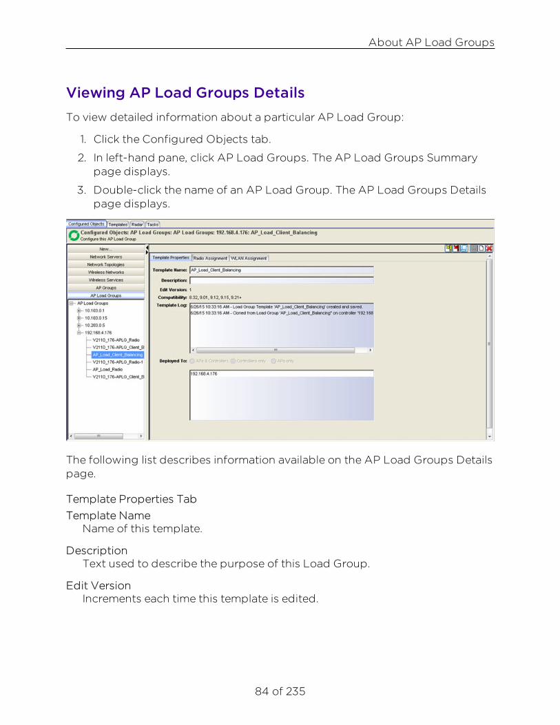
About AP Load Groups
84 of 235
Viewing AP Load Groups DetailsTo view detailed information about a particular AP Load Group:
1. Click the Configured Objects tab.
2. In left-hand pane, click AP Load Groups. The AP Load Groups Summarypage displays.
3. Double-click the name of an AP Load Group. The AP Load Groups Detailspage displays.
The following list describes information available on the AP Load Groups Detailspage.
Template Properties TabTemplate Name
Name of this template.
DescriptionText used to describe the purpose of this Load Group.
Edit VersionIncrements each time this template is edited.

About AP Load Groups
85 of 235
CompatibilityDisplays the versions of the Wireless Controller software that are compatiblewith this template (see Template Versions).
Template LogThe history lists significant events in the life of the template, such as when itwas created, when it was changed, and when it was deployed.
Deployed toLists the Wireless Controllers to which this scan profile template is deployed.
Radio Assignment TabLoad Group ID
Name of this Load Group.
TypeType of Load Group. Set to Client Balancing.
Select AP radiosSelect the radios assigned to this Load Group. Possible values are: All radios,Radio 1, Radio 2, Clear all Selections.
ControllerName of the Wireless Controller assigned to this Load Group. Select acontroller from the drop-down menu.
Radio Preference TabLoad Group ID
Name of this Load Group.
TypeType of Load Group. Set to Radio Balancing.
ControllerName of the Wireless Controller assigned to this Load Group. Select acontroller from the drop-down menu.
Band PreferenceSelect the checkbox to enable band preferences for this Load Group.
Load ControlSelect the following parameters for each radio assigned to this load group:
l Enable - Select this checkbox to enable Radio Load Control (RLC) forindividual radios (Radio1 and Radio2) associated with this Load Group.

About AP Load Groups
86 of 235
l Max # of Clients - Enter the maximum number of clients for Radio 1 andRadio 2. The default limit is 60. The valid range is: 5 to 60.
l Strict Limit - Select this checkbox to enable a strict limit on the number ofclients allowed on a specific radio, based on the max # of clients allowed.Limits can be enforced separately for radio1 and radio 2.
WLAN Assignment TabTemplate Name
Name of this template.
WLAN NameName of this WLAN.
Toolbar ButtonsFor a description of common toolbar buttons see Context-Sensitive Toolbar.
Creating an AP Load GroupWhen creating an AP Load Group, you can only select APs/radios from a singleWireless Controller to become members of the group. After you create the APLoad Group, Wireless Manager generates an audit record that shows the nameof the AP Load Group, the user ID of the account that created it, and the dateand time when it was created.
To create an AP Load Group:
1. Click the Configured Objects tab.
2. In left-hand pane, click AP Load Groups. The AP Load Groups Summarypage displays.
3. Click on the New icon in the tool bar. The AP Load Group Details pagedisplays.
4. In the Template Name field, enter a name for the Wireless Controller.
5. In Description field, describe the purpose of this Load Group.
6. Click the Radio Assignment tab and enter the following information:
l Enter a Load Group ID.
l Select the Load Group Type.
l Select a Wireless Controller from the list of available controllers.
l Select AP radios.

About AP Load Groups
87 of 235
7. Click the Save icon to save the AP Load Group configuration.
You can also access the Create New AP Load Group page from the ConfiguredObjects tab by clicking New > AP Load Group or from the AP Load GroupSummary page by right-clicking on a Wireless Controller name and selecting theNew icon.
Editing an AP Load GroupTo edit an AP Load Group configuration:
1. Click the Configured Objects tab.
2. In left-hand pane, click AP Load Groups. The AP Load Groups Summarypage displays.
3. Select an AP Load Group from the list on the AP Load Groups Summarypage.
4. Click the Edit icon. The AP Load Groups Details page displays. You canchange the APs/radios included in the AP Load Group as well as the BandPreferences and Load Control settings for radio balancing Load Groups.
5. Click OK to save the changes.
Deleting an AP Load GroupTo delete an AP Load Group configuration:
1. Click the Configured Objects tab.
2. In left-hand pane, click AP Load Groups. The AP Load Groups Summarypage displays.
3. Select an AP Load Group from the list on the AP Load Groups Summarypage.
4. Click the Delete icon. Wireless Manager prompts to verify that you want todelete the selected AP Load Group. Click OK to continue or Cancel to abortthe AP Load Group deletion.
You can also delete an AP Load Group from the AP Load Group Details page.

88 of 235
Managing Templates
Templates are global configurations that provide a simple, centralized view ofhow the network ought to be configured. You can create a new template, orclone an existing configuration and modify it to create a new template.
A template takes effect after you create a task to deploy it.
This section includes the following topics:
l About Templates
l About Globals Templates
l About Virtual Network Service (VNS) Templates
l About WLAN Service Templates
l About Role Templates
l About Rate Profiles
l About AP Profiles
l About Classes of Service Templates
89 of 235
About Templates
Templates enable you to create one configuration and either store thatconfiguration for later use or deploy it to one or more targets simultaneously.Although you can apply the same template to multiple targets, some templatesare more useful with customizations that you can apply when you deploy thetemplate. For example, a VNS template that makes use of a particular VLANwould be much less useful if it forced the administrator to use the same physicalport on each target Wireless Controller as the point of attachment to the VLAN.Similarly, you must assign a different subnet range to a routed topology whenyou deploy a template to different Wireless Controllers. Most templates permityou to customize some settings for each Wireless Controller to which thetemplate is deployed. You can customize some template settings for eachWireless Controller when you deploy the template.
Some types of templates, such as an AP profile template, do not need any per-Wireless Controller customizations. In this case, you can clone an existingtemplate or configuration, make modifications, and save it as a new template.
The template, with its per-Wireless Controller customizations, provides a singlepoint in the UI where you can see how a VNS should be deployed across yourWireless Controllers.
This Help topic includes the following information:
l Template Versions
l Resolving Template Conflicts
l Resolving Duplicate Templates
Template Versionsl Compatibility Versions - In past releases, different versions of Policy and
Topology templates were only compatible with specific versions ofWireless Controllers. Consequently, to help avoid conflicting versions oftemplates and to clarify why certain deployment targets were not availablefor selection, a Compatibility parameter was added to each template'sgeneral properties page. In this release however, all templates aredeployable to 8.01 or later Wireless Controllers, within the followingguidelines:

About Templates
90 of 235
l When migrating from an earlier release of Wireless Manager anyV7.31/7.41-Advanced Mode Compatible Policy templates as well asV7.31 - Compatible Topology templates are automatically upgraded toV8.01+ Compatible templates. These templates will appear directlyunder the Legacy folder in their corresponding sections in theNavigation Tree.
l After the legacy template migration period has expired, any legacytemplates (Roles, CoS and Rate Profiles) remaining cannot bedeployed. Use Policy Manager to configure these entities on thecontroller. See Legacy Template Notification.
n Edit versions — Wireless Manager does not keep historical copies oftemplates. The edit version is represented by a version number thatincrements each time you successfully save a template. The edit versionnumber is used primarily to annotate logs pertaining to templates, so thatwhen looking at a template’s historical logs, you can determine whether:
l The template is deployed multiple times.
l The same template was deployed (the same edit-version wasdeployed each time) or different versions of the template weredeployed (different edit-version numbers).
Resolving Template ConflictsAfter template deployment, Wireless Manager audits the Wireless Controllerconfigurations to ensure that the Wireless Controller configurations do notdeviate from the deployed template. When it encounters discrepancies betweenwhat ought to be deployed (the template) and what actually is deployed (theWireless Controller or AP configuration), the Wireless Manager audit featurelogs an error.
To address any discrepancies, you can manually launch the Conflict Resolutionwizard. Otherwise, when you log in next, Wireless Manager automaticallylaunches the wizard. Using the wizard, you can choose to address and resolveany deviations, or to accept them.
To launch the Conflict Resolution wizard:
1. From the Wireless Manager top banner, click on the Resolve Audit Conflictsbutton .
2. For each template that does not match the actual target configuration,select how you would like to resolve the conflict. After the conflict is

About Templates
91 of 235
resolved, the deployment wizards will launch for those templates thatrequire deployment.
3. In the Filter By Type field, you can filter the list of templates which haveconflicts to display only those of a particular template type.
4. In the Action field, select one of the following:
l Do Nothing – Select this option to stop being reminded of thediscrepancy between the configuration in Wireless Manager and onthe Wireless Controllers.
l Remind me later – Select to postpone resolving any conflicts.
l Remove from targets – Select to resolve the conflict by removing fromthe scope of the template those targets that have conflictingconfigurations. This will not cause changes to either the WirelessManager template, or the Wireless Controller’s or AP’s configuration.
l Use changed settings – Select to resolve the conflict by cloning theconfiguration of one of the conflicting targets and deploying it to allof the template’s targets.
l Redeploy and overwrite – Select to resolve the conflict by redeployingthe template as it is defined on Wireless Manager to all of the targets.When you redeploy a template to all targets, the template overwritesthe conflicting settings on the conflicting targets.
5. Click Finish.
6. A message displays whether or not the selected action was successful. Astatus bar shows the percentage of completion.
Resolving Duplicate Templates
In previous releases of Wireless Manager, selecting the clone and retrievefeatures did not properly merge entities resulting in duplicate versions of thesame template. Now using the Duplicate Resolution wizard, you can haveWireless Manager automatically detect and merge duplicate templates.
To launch the Duplicate Resolution wizard:
1. From the Wireless Manager top banner, click on the Resolve Duplicatesbutton .
2. In the Filter By Type field, you can filter the list of templates which haveduplicates to display only those of a particular template type.

About Templates
92 of 235
3. In the Selection field, select one of the following:
l Resolve Automatically – Select this option to have Wireless Managerresolve the duplicate template.
l Select a template – Select a template from a list of existing templates.
4. Click Finish.

93 of 235
Editing Templates
You can edit the following template types at any time: Globals, Virtual Networks(VNS), WLAN Services, and Access Points. Changes will not take effect until youcreate a task to deploy the modified template.
NOTE:Wireless Manager no longer supports the configuration or editing of Role, RateProfiles, and Classes of Service templates.
To edit a template:
1. Click the Templates tab.
2. In the left pane, select the type of template you want to edit. The Summarypage displays.
3. Select a template in the Summary page and either click the edit icon at thetop of the page or right-click on the template name and select Edit fromthe drop-down menu. You can also expand the template folder in the leftpane and select a template to edit.
4. The Template Configuration tabs display with the Template Properties Tabactive. Move between the tabs and change the settings as desired.
5. Click the Save button to save the changes.
Related Informationl About Templates
l Deleting Templates

94 of 235
Deleting Templates
You can delete any template (except for Roles, Rate Profiles, and Classes ofService) using the Delete wizard.
1. Click the Templates tab.
2. Navigate to a Summary page for the configuration you want to delete.
3. Either click the delete icon at the top of the page or right-click on thetemplate name and select Delete from the drop-down menu. The Deletewizard launches.
4. Select delete options. The Delete wizard offers options for cleaning uptasks that were created from the template. In addition, it may offer theoption of undeploying the template from any of the template’s targets.From the options listed, select the deletion and undeployment tasks youwant to perform. Then, click Next to continue.
5. Deselect controller for removal (optional). The Delete wizard offers optionsfor cleaning up tasks that were created from the template. In addition somewizards offer the option of undeploying the template from any of thetemplate's targets.
6. Select Target to Delete. Select a target from which you want to undeploy atemplate. Click Next.
7. Execute Task. The window displays a status bar that shows the task as itcompletes. After the task is complete, the system identifies whether theaction succeeded or failed.
Related Informationl About Templates
l Editing Templates
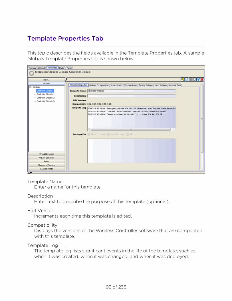
95 of 235
Template Properties Tab
This topic describes the fields available in the Template Properties tab. A sampleGlobals Template Properties tab is shown below.
Template NameEnter a name for this template.
DescriptionEnter text to describe the purpose of this template (optional).
Edit VersionIncrements each time this template is edited.
CompatibilityDisplays the versions of the Wireless Controller software that are compatiblewith this template.
Template LogThe template log lists significant events in the life of the template, such aswhen it was created, when it was changed, and when it was deployed.

About Templates
96 of 235
Deployed toLists the Wireless Controllers, APs, AP Groups, and AP Load Groups (asapplicable for the template type) to which the template is deployed.
Toolbar Buttons
For a description of common toolbar buttons see Context-Sensitive Toolbar.
Related Informationl About Templates
l Deleting Templates
l Editing Templates

97 of 235
Viewing Detailed Template Information
You can view detailed information about a particular template using thetemplate configuration tabs. Using the toolbar in the tabs, you can also performthe following tasks:
l Deploy or undeploy the template.
l Clone or delete an existing template.
l Edit the template configuration.
l Export a template to the CLI.
l Create a new template definition.
To view detailed information about a template:
1. Click the Templates tab.
2. Expand the template folder in the left pane and select the template youwant to view.
3. The Template Configuration tabs display with the Template Properties tabactive.
Related Informationl About Templates
l About Radar

98 of 235
About Globals Templates
A Globals template is a general template for configuring global settings on awireless controller. The settings configured using a Globals template aregrouped into the following categories which can be independently configured:
l Administration - Includes Jumbo Frame Support, Synchronize SystemConfiguration (only applicable for availability pairs)
l System Logs - System Log Level, Report station events, Send/forwardstation sessions
l Syslog Settings - Syslog, Facilities (Application Logs, Service Logs, AuditLogs, Station Logs)
l Web Settings - Web Management Settings
l Network Time - Time Zone Settings, System Time, NTP
l Location Settings - Environment Settings, Location Targets, Location BatchReporting
l Authentication Settings - RADIUS Servers
l Wireless QoS Settings - Configure Admission Control Thresholds andflexible client access.
l Topology Groups Settings - Algorithms for selecting a member topologyfrom a topology group.
This Help topic includes the following information:
l Creating a Globals Template
l Manually Creating a Globals Template
l Cloning Globals
l Viewing Summary Information About All Globals Templates
Creating a Globals TemplateYou can create a Globals template either manually, or by cloning it fromdeployed Globals or an existing template.
Manually Creating a Globals Template
To manually create a Globals template:

About Globals Templates
99 of 235
1. Click the Templates tab.
2. In the left pane, click New, expand the New folder and click Add Globals.The Globals Template Configuration page displays with the TemplateProperties tab active.
3. Enter a name for the new template. Enter a template description, if desired.For more information about the fields on this tab, see the TemplateProperties Tab Help topic.
4. Click on the Globals Configuration tab. Select the categories you want toconfigure. For each selection, a corresponding tab appears. Each of thedifferent tabs are described below.
Administration TabJumbo Frame Support
This feature can be enabled on v9.01 or later controllers. It is supported on thefollowing hardware platforms:
Wireless Controllers:
l Supported: C35, C4110, C5110 and C5210
l Not supported: C25, WLC711 and V2110

About Globals Templates
100 of 235
Access Points:
l Supported: 37xx APs (except 3705) and 38xx APs
l Not supported: AP26xx, AP36xx, and AP3705
Enabling this feature affects the maximum L3 MTU size for APs andTopologies
Topology Interface L3 MTU:
l For routed topologies: 1436 / 1736 (with Jumbo Frames)
l For BAC topologies: 1500 / 1800 (with Jumbo Frames)
l For Admin / Physical topologies (not supported by WirelessManager)
AP Tunnel MTU
l For the ABG, ABGN, Dual Band ABG, RoamAbout AP profilesthis attribute hasn’t changed; valid range of [600-1500]
l For 37xx & 38xx AP profiles the valid range has increased to[600-1800] bytes.
l If MTU > 1500, Ethernet speed setting MUST be Auto(default) / 1 Gbps (not 10/100 Mbps).
l If EWC / AP doesn't support jumbo frames, or it is disabled:
Template Value: x < 1500, 1500 <= x <=1800
Deployed Value: x < 1500 (no change), x=1500
l If EWC supports jumbo frames AND AP supports jumboframes AND it is enabled:
Template Value: x <=1800
Deployed Value: x<=1800 (no change)
In other words, whatever is specified in thetemplate is what gets deployed.
Synchronize System ConfigurationSelect this checkbox to push the configured VNS definitions from the primarycontroller to its availability partner.
About Globals Templates
101 of 235
l WDS, Mesh and 3rd Party AP VNS definitions are not synchronized.
l Synchronizing VNS definitions deletes and replaces any existing VNSdefinitions on the peer controller.
l All VNS parts are synchronized (VNS, WLANs, Roles, Topologies, CoS)
A Globals Template is always deployed to all target controllers regardless oftheir paired status and whether or not "Synchronize System Configuration" isenabled. For other types of templates:
l If this setting is enabled, Wireless Manager will only deploy to one of thecontrollers in an availability pair and leave it to that controller to sync withits peer; the audit process detects any discrepancies.
l If this setting is not enabled, Wireless Manager will deploy to eachcontroller in an availability pair.
System Logs TabSystem Log Level
Wireless Controller & AP Log Levels: Critical, Major, Minor, and Information.
l Critical, Major and Minor level logs are considered to be alarmconditions.
l Information level logs are considered to represent normaloperation.
Report station events on controllerClick to collect and display station session events on the controller’s StationEvents log.
Send station session to NetSightClick to forward station session events to NetSight for monitoring.
Forward station session events as trapsClick to forward station events as SNMP traps.
Syslog Settings TabSyslog
Enable the Syslog function for up to three syslog servers.The default syslogport (514) cannot be changed. The following settings apply to all configuredservers:

About Globals Templates
102 of 235
l Include all Service Messages:
o Disabled: Only component messages (logs and traces) are relayed.
o Enabled: Logs, traces and DHCP messages are relayed.
l Include Audit Messages: relays audit messages.
l Include Station Event Messages: relays station session event messages.
FacilitiesFacilities – set level (Local0, Local1, Local3, Local4, Local5, Local6) to be sentto syslog server for:
l Application Logs
l Service Logs (only enabled if Include all Service Messages is selected)
l Audit Logs (only enabled if Include Audit Messages is selected)
l Station Logs (only enabled if Include Station Event Messages is selected)
Web Settings TabWeb Management Settings
These fields can be entered as hour:minutes, or just minutes. Valid range: 1minute to 168 hours (or 7 days).
l Web Session Timeout: The length of time that a web session can remaininactive before it times out.
l GuestPortal Manager Web Session Timeout: Same as Web Session Timeoutbut applies to users of group GuestPortal Manager.
Show WLAN names on the Wireless AP SSID listSelect to allow the names of the WLAN services to appear in the SSID list forWireless APs.
Network Time TabTime Zone Settings
l Continent or Ocean: Large-scale geographic region.
l Country: Contents of drop down change based on the “Continent orOcean” selected.
l Time Zone Region: Lists those time zone regions appropriate for theselected country.
System TimeSelect Configure System Time to set the system time directly.

About Globals Templates
103 of 235
l Use Deployment Time: Can be scheduled in the future. Converts theserver’s time into the Wireless Controller's target time zone.
l Set Time: Only makes sense for immediate execution. Entered as mm-dd-yyyy hh:mm. It is assumed to be with respect to the Wireless Controller'starget time zone.
NTPSelect Enable to configure NTP. If the Wireless Controller cannot connect toTime Server 1, it will attempt to connect to any additional servers specified.The Time Server fields support IP addresses (IPv4 / IPv6) or FQDNs.
If no Time Servers are specified, "Run local NTP Server" must be selected.
Location Settings TabLocation Engine Settings
Select Enable to configure Location Engine Settings. The Location EngineSettings section of the window allows you to configure the environment inwhich the AP is functioning to provide greater accuracy. Additionally, withinthe Location Targets section of the window, you can locate active sessions ofusers connected to the AP and track users as they move between areas inmaps you configure through the use of triangulation, by selecting the LocateActive Sessions and Track Area Change checkboxes, respectively. Areas areconfigured in maps on the Network tab in Extreme Management Center. Foradditional information about configuring areas in maps, see Configure Areawindow.
Environmental Settings
l Default AP Height (cm): Enter the height of the wall-mounted AP incentimeters.
l Default Environmental Model: Select a mode that best matches theenvironment identified by the floor plan. Choose from one of the followingmodes from the drop-down list:
o Indoor open space (halls, auditoriums)
o Office Environment with light divisions (cubicles)
o Office Environment with dry wall divisions
o Office Environment with hard divisions (brick)
o Interior Walls (need be defined in the floor plan)

About Globals Templates
104 of 235
Location Targets
l Locate Active Sessions: Click to locate all active users located within thesignal range.
Location Batch ReportingSelect Enable to configure Location Batch Reporting.
l Report all station locations every (X) minutes: Select a time (in minutes) forstation reporting from the drop-down list.
l Dimension Unit: Select a dimension unit, from the drop-down list, formeasuring location destinations.
l Post all location destinations to the following URLs: List of destinationURLs.
Authentication Settings TabRADIUS Servers
Select to enable Strict Mode. When Strict Mode is enabled, all WLANs on acontroller that require RADIUS Servers will use the top three global RADIUSservers configured for ‘Auth’ and ‘Acct’ accordingly. If the prioritization ofthese global RADIUS servers changes so will those referenced by theWLANs.
MAC Address Format: Configure the global MAC address format to use withthe RADIUS Servers from the drop-down.
Advanced buttonClick the Include the Service-Type attribute in Client Access Requestmessages checkbox to include Service-Type attribute in Client AccessRequest messages. Default is disabled.
If the Include the Service-Type attribute in Client Access Request messagescheckbox is selected, the Set Service-Type to Login checkbox is available.Click the Set Service-Type to Login checkbox to set the Service-Typeattribute to Login. When this option is not selected, the Service-Typeattribute in the Attribute-Request message is set to Framed. Default isdisabled.
NOTE: If the Wireless Controller is using the RADIUS login, this option is notavailable.
Enter the number of seconds to set the Delay for Client Message forTopology Change. This setting specifies how long a notice web pagedisplays if a topology change occurs during authentication as a result of a

About Globals Templates
105 of 235
role change. The notice web page indicates that authentication wassuccessful and that the user must restart the browser to gain access to thenetwork.
For Authentication, select one of the following options:
l Send requests to Primary whenever it is up (Primary-Backup). Gives theadministrator the ability to configure whether the primary server shouldresume client authentication when it has recovered. Currently it is onlysupported for RADIUS authentication and not accounting.
l Send request to one server until it fails (Round-Robin). When multipleRADIUS servers are specified for client authentication, one server is used asthe primary server, but if that server fails then authentication is transferredto the next server, and so on. Only the last working RADIUS server remainsactive in authenticating clients.
Select the RADIUS Accounting checkbox to activate RADIUS accounting forWLAN Services for which RADIUS accounting is configured. Default isenabled.
NOTE: Disabling the Radius Accounting checkbox overrides theRADIUS accounting settings of individual WLAN services. EnablingRADIUS accounting activates RADIUS accounting only in WLAN servicesspecifically configured to perform it.
Select Defer sending the accounting start request until the client's IP addressis known to configure the start of RADIUS accounting to occur after the clientreceives an IP address.
Wireless QoS TabAdmission Control Thresholds
Select the percentage of bandwidth for the following streams:
l Max Voice (VO) BW for roaming streams - Set the maximum percentage ofbandwidth for roaming voice streams as a percentage of the totalbandwidth.
l Max Voice (VO) BW for new streams - Set the maximum percentage ofbandwidth for new voice streams as a percentage of the total bandwidth.
l Max Video (VI) BW for roaming streams - Set the maximum percentage ofbandwidth for roaming video streams as a percentage of the totalbandwidth.

About Globals Templates
106 of 235
l Max Video (VI) BW for new streams - Set the maximum percentage ofbandwidth for new video streams as a percentage of the total bandwidth.
l Max Best Effort (BE) BW for roaming streams - Set the maximum besteffort bandwidth for roaming streams as a percentage of the totalbandwidth.
l Max Best Effort (BE) BW for new streams - Set the maximum best effortbandwidth for new streams as a percentage of the total bandwidth.
l Max Background (BK) BW for roaming streams - Set the maximumbackground bandwidth for roaming streams as a percentage of the totalbandwidth.
l Max Background (BK) BW for new streams - Set the maximumbackground bandwidth for new streams as a percentage of the totalbandwidth.
Flexible Client AccessSelect the airtime or packet fairness for WLAN participants. Airtime fairnessgives WLAN participants the same time access and a client's throughput isproportional to their PHY rate. Packet fairness gives WLAN participants thesame opportunity to send packets and all clients will show the samethroughput, regardless of PHY rate.
NOTE: Flexible Client Access may not work if Global Admission Controls forVoice, Video, Best Effort, or Background are enabled.
Topology Groups Settings TabTopology Group Selection Algorithm
Select the algorithm used to select a topology from a topology group.Options include:
l MAC Based - The topology is selected by converting the MAC address to anumber, dividing that number by the number of topologies in the group,and using the topology that corresponds to the resulting number.
l Round Robin - The topologies are listed in order and each topology isselected in turn.
l Random Selected - The topologies are randomly selected uniformly.
l Least Used - The topology to which the least number of stations assignedis selected at the moment of assignment is selected.
Toolbar ButtonsFor a description of common toolbar buttons see Context-Sensitive Toolbar.
About Globals Templates
107 of 235
Cloning Globals
To create a Globals template by cloning an existing template or configuration:
1. Click the Templates tab.
2. In the left pane, click New, expand the Clone folder and click Clone Globals.The Clone Globals wizard launches.
3. On the Cloning Source dialog, enter a name for the new template in theNew Template Name field.
4. Select one of the following:
l Base template on a deployed Globals – This option lets you create atemplate by copying those global settings, which Wireless Managerallows you to configure, from a Wireless Controller.
l Base template on an existing Globals – This option lets you create atemplate by copying the settings of another already existing Globalstemplate.
5. The window that lists the selected items becomes active. Click the ViewSelected button to view detailed information about the cloning source.
6. Click Next.
7. The Cloning Summary page displays the Globals configuration that youselected. Click Finish to clone the Globals template or Cancel to discard it.
Viewing Summary Information About All GlobalsTemplatesYou can view summary information about Globals currently defined in WirelessManager from the Globals Summary page. From this page, you can also performthe following tasks:
l Deploy or undeploy the template.
l Edit, clone, or delete an existing Global definition.
l Export a Global configuration to the CLI.
l Create new Global definition.
To view summary information about configured Global:
1. Click the Templates tab.
2. In left-hand pane, click Globals. The Globals Summary page displays.

About Globals Templates
108 of 235
The following list describes the information available on the Globals page.
StatusStatus of this Global. Options include:
Deployed, Not Deployed, Deployed but not synchronized to thenetwork,
Deployed but some templates not synchronized.
NameName assigned to the Global.
AdministrationIndicates if Administration settings are deployed to the Wireless Controller.Options are: enabled or disabled.
System LogsIndicates if System Logs settings are deployed to the Wireless Controller.Options are: enabled or disabled.
SyslogIndicates if Syslog settings are deployed to the Wireless Controller. Optionsare: enabled or disabled.
WebIndicates if web settings are deployed to the Wireless Controller. Options are:enabled or disabled.

About Globals Templates
109 of 235
Network TimeIndicates if Network Time settings are deployed to the Wireless Controller.Options are: enabled or disabled.
ControllersWireless Controller to which this Globals template has been deployed.
LocationIndicates if this Globals template defines Location related settings (Engine /Batch Reporting) to be deployed to target Wireless Controllers.
AuthenticationIndicates if this Globals template defines Authentication related settings tobe deployed to target Wireless Controllers.
Toolbar ButtonsFor a description of common toolbar buttons see Context-Sensitive Toolbar.
Related Informationl Deleting Templates
l Editing Templates
l Viewing Detailed Template Information

110 of 235
About Virtual Network Service (VNS) Templates
A Virtual Network Service (VNS) is a binding of several reusable componentsthat together provide a versatile method of mapping wireless networks to thetopology of an existing wired network. It is composed of a WLAN service withone or more roles that control the wireless station's access to the wired network.
If you are not using the VNS wizard to create a VNS template, you shouldalready have configured templates for the following elements:
l Topologies - A topology is a combination of Layer 2 and if applicable,Layer 3 networking attributes.
l Class of Services - A CoS refers to the set of attributes that define theimportance of a frame relative to others on the network. It is a configurationentity containing QoS Marking (802.1p and ToS/DSCP),Inbound/Outbound Rate Limiting and Transmit Queue Assignments.
l Roles - A role defines the default access control, egress VLANs, filter rules,and Class of Service to be applied to the traffic of a station.
l WLAN Services - A WLAN Service defines and the radio attributes, privacyand authentication settings, and QoS attributes of the VNS.
This Help topic includes the following information:
l Creating a VNS Template
l Viewing Summary Information About All VNSs
Creating a VNS TemplateWhen using the VNS wizard, you can create a VNS for many different purposes,including:
l Voice - Voice-specific VNS that can support various wireless telephones,including WL2, SpectraLink, Polycom Spectralink 8000, ASCOM - i62,Vocera - Smartphone, Vocera - B2000, Vocera - B1000, Mobile Connect -Nokia.
l Data - Data-specific VNS, that can be configured to use either SSID or AAAauthentication.
l Captive Portal/NAC-Compatible Captive Portal-based VNS - A VNS thatemploys a Captive Portal page, which requires mobile users to provide
About Virtual Network Service (VNS) Templates
111 of 235
login credentials when prompted to access network services. In addition,use the VNS wizard to configure a GuestPortal VNS using the CaptivePortal option.
l NAC Compatible EAP-based VNS - NAC EAP-compatible VNS. TheExtremeWireless Wireless Controller integrates with an EOS NACController to provide authentication, assessment, remediation and accesscontrol for mobile users.
The VNS type dictates the configuration information that is required during theVNS creation process.
There are three ways that you can create a VNS template. For instructions, see:
l Creating a VNS Configuration Using the VNS Wizard
l Manually Creating a New VNS Configuration
l Cloning an Existing VNS
The VNS configuration does not take effect until you create a task to deploy it.
Creating a VNS Configuration Using the VNS Wizard
The VNS wizard steps you through the configuration and prompts you for aminimum amount of configuration information. After the VNS wizard completesthe VNS template creation process, you can then continue to configure or revisethe VNS template configuration to suit your network needs.
Using the VNS wizard you can create VNS that are deployable to Policy Manager(PM) managed Wireless Controllers and non-PM managed Wireless Controllers.However, after the legacy template migration period has expired, you can onlycreate VNS deployable to PM managed EWCs (see Legacy Template MigrationNotice). A controller is considered managed by Policy Manager if it is assignedto a Policy Manager domain. By default, the VNS wizard creates a VNS whichcan be deployed to PM managed Wireless Controllers. If you want to create a'Legacy' VNS that can be deployed to non-PM managed Wireless Controllers,click the Legacy checkbox on the first page of the wizard.
To launch the VNS Wizard:
1. Click the Templates tab.
2. In left-hand pane, click New, expand New and click Start VNS Wizard. TheVNS Template Configuration wizard launches.

About Virtual Network Service (VNS) Templates
112 of 235
3. Enter a unique name for the VNS.
4. Select the category of VNS you want to create. Options include:
l Voice
l Data
l Captive Portal
l NAC-compatible Captive Portal-based VNS
l NAC-compatible EAP-based VNS
5. Click Legacy to create a VNS that can only be deployed to non-PMmanaged Wireless Controllers.
6. Click Next. The Set Basic Settings Window displays.
Set Basic Settings Window
NOTE:The contents of the basic settings window will vary based on the type of VNS that youare creating.
7. Click Enabled to enable this VNS by default.
8. In the SSID field, enter an SSID. By default, the value you specified in theName field in the previous window automatically populates this field.
9. In the Type field, select the type of VNS you want to create from the drop-down menu. This field is not present for Data VNS.
10. In the Mode field, select the type of topology. Depending on the categoryof the VNS and whether or not it is a Legacy VNS, options may include:
l Routed
l Bridged Traffic Locally at AP (B@AP)
l Bridge Traffic Locally at Wireless Controller (B@EWC)
11. Specify a VLAN ID. For a Legacy VNS with a mode of B@AP or B@EWCspecify whether it is tagged and if necessary its VLAN ID.
12. For a Voice VNS, enter an IP address for the PBX server/Gateway -SVP/Vocera Server.
13. If available, select Enable Authentication to enable authentication on thisVNS.
14. If available, select Enable Filtering to enable filtering for this VNS.
15. Click Next.
About Virtual Network Service (VNS) Templates
113 of 235
Define Privacy Settings
16. Select the privacy settings. The privacy settings that you can configure willdiffer depending on the kind of VNS being created.
Set Authentication
NOTE:Some types of VNS, such as a NAC compatible VNS, do not require input onauthentication settings and will skip this window.
17. Select a RADIUS server to be used for authentication from the drop-downmenu.
18. If a suitable RADIUS server does not exist, click New to create a newRADIUS server configuration.
NOTE:You can override this selection after you have selected the Wireless Controllers towhich to deploy this VNS.
You can optionally choose MAC-based authentication. Additional authenticationsettings depend on the target Wireless Controller. You can specify thesesettings when you deploy this template.
Summary
19. Review the summary information. To change any settings, use the <Prevbutton. Click Finish to create the VNS template using the settings specified.
After the template is successfully created, you can deploy it by clicking theDeploy button in the Creation of VNS Template window.
Manually Creating a New VNS Configuration
To manually create a VNS template:
1. Click the Templates tab.
2. In left-hand pane, click New, expand New and click Add VNS (subnet). TheVNS Configuration page displays with the Template Properties tab active.

About Virtual Network Service (VNS) Templates
114 of 235
3. Enter a name for the new template. Enter a template description, if desired.For more information about the fields on this tab, see the TemplateProperties Tab Help topic.
4. Click the VNS Core Properties tab.
5. In the Core area, enter the Name of the VNS.
6. In the WLAN Service area, select the name of the WLAN service from thedrop-down menu. If a suitable WLAN service does not exist, you can createone. For more information, go to Creating a WLAN Service Template.
7. In the Default Roles area:
a. Select a Non-Authenticated role from the drop-down list. A Non-Authenticated role is the role applied by default to a station prior tothe station authenticating via 802.1x or captive portal.
b. Optionally select an Authenticated role from the drop-down list. AnAuthenticated role is the role applied by default to any station thatauthenticates successfully and for which no other role has beenassigned explicitly.
8. In the Status area, select Enable to enable this VNS when it is deployed.
9. Click the Per Controller Settings tab.
a. In the Topology Per Controller Settings area, view the Topologysettings for both Authenticated and Non-Authenticated Roles.

About Virtual Network Service (VNS) Templates
115 of 235
b. In the WLAN Service Per Controller Settings, view the RADIUS serverand Captive Portal settings.
10. Click Save to save the VNS.
Cloning an Existing VNS
You can clone an existing VNS template or VNS configuration and modify it tocreate a new template or configuration.
To launch the Clone VNS wizard:
1. Click the Templates tab.
2. In left-hand pane, click the New bar, expand Clone and select Clone VNS.The Clone VNS wizard launches.
3. On the Select Cloning Source dialog, in the New template name field, entera name for the new VNS.
4. Select one of the following:
l Base template on a deployed VNS – This options lets you create atemplate by copying the settings of a VNS deployed on a WirelessController.
l Base template on an existing VNS – This option lets you create atemplate by copying a template that already exists on the WirelessController.
5. The window that lists the selected item becomes active. Click the ViewSelected button to view detailed information about the cloning source.
6. Click Next.
7. The Cloning Summary page displays the configuration that you selected.Click Finish to clone the configuration or Cancel to discard it.
NOTE:When you create a clone of a template that references other templates, the clone willcontinue to reference the same child templates as the original template; it is a shallowclone. Similarly, when you clone a template based on a deployed entity, if a templatealready exists for a child entity it will be reference by the clone, otherwise a newtemplate is created.
Viewing Summary Information About All VNSsYou can view summary information about VNS templates or configurationscurrently defined in Wireless Manager from the VNS Summary page. From this

About Virtual Network Service (VNS) Templates
116 of 235
page, you can also perform the following tasks:
l Deploy or undeploy the template.
l Edit, clone, or delete an existing VNS definition.
l Export a VNS configuration to the CLI.
l Create new VNS definition.
To view information about a configured VNS:
1. Click the Templates tab
2. In left-hand pane, click VNS. The VNS Summary page displays.
The following list describes the information available on the VNS Summary page.
StatusStatus of this VNS. Options include:
Deployed, Not Deployed, Deployed but not synchronized to thenetwork,
Deployed but some child templates are not synchronized,
Incomplete - The definition of this template must be completed before itcan be deployed.
NameName of the VNS. This name can be the same as the VNS template name, or itcan be a different name.
EnabledState of the VNS; the VNS is deployed in an enabled or disabled state.

About Virtual Network Service (VNS) Templates
117 of 235
WLAN ServiceThe WLAN service used in this VNS.
AuthThe authentication method used by this VNS.
PrivacyThe privacy setting for this VNS.
Def. RoleThe role used by this VNS.
TopologyThe topology used by this VNS.
ModeThe mode of operation of the topology. Values are: Routed, B@AP, orB@EWC used by this VNS.
ControllersList of Wireless Controllers that use this VNS.
Toolbar ButtonsFor a description of common toolbar buttons see Context-Sensitive Toolbar.
Related Informationl Deleting Templates
l Editing Templates
l Viewing Detailed Template Information

118 of 235
About WLAN Service Templates
A WLAN Service represents all the RF, authentication and QoS attributes of awireless access service offered by the Wireless Controller and its APs. WirelessManager only supports the configuration of standard and remotable WLANServices.
Standard - Only APs running ExtremeWireless Wireless software can be part ofthis WLAN Service. This type of service may be used as a Bridged at Controller,Bridged at AP, or Routed VNS. This type of service provides access for mobilestations. Therefore, roles can be assigned to this type of WLAN service to createa VNS.
Remotable - Any WLAN service can be made remotable by selecting thisproperty in its Advanced settings dialog. When deploying a remotable WLAN,for each Mobility Zone identified among the selected targets you must chooseone Wireless Controller (its home controller) where it will be deployed asremotable; any other selected targets in that Mobility Zone will receive theremote definition of the WLAN. A remote service definition doesn't include anyAuth & Acct settings, but should have the same SSID name and privacy settingsas its corresponding remotable service.
This Help topic includes the following information:
l Creating a WLAN Service Template
l Viewing Summary Information About All WLAN Services Templates
Creating a WLAN Service TemplateYou can create a WLAN Service template either manually, or by cloning anexisting template or a WLAN Service configuration. When you create a WLANService template, you perform the following tasks:
l Define SSID and privacy settings for the wireless link.
l Configure the method of credential authentication for wireless users (None,Internal CP, External CP, GuestPortal, 802.1x[EAP]).
l Configure QoS settings for stations accessing the network through thisWLAN Service.

About WLAN Service Templates
119 of 235
Manually Creating a WLAN Service Template
To manually create a WLAN Service template:
1. Click the Templates tab.
2. In the left pane, expand New and click Add WLAN Service. The WLANService Template Configuration page displays with the TemplateProperties tab active.
3. Enter a name for the new template. Enter a template description, if desired.For more information about the fields on this tab, see the TemplateProperties Tab Help topic.
4. Use the other tabs to configure your template. Each of the different tabsare described below.

About WLAN Service Templates
120 of 235
WLAN Service Tab
Core
NameName of this WLAN Service. This name can be the same as the WLANService template name, or it can be a different name.
SSIDService Set Identifier (SSID) is the name of a wireless local area network(WLAN).
NOTE:To prevent the configuration of an unsecure WLAN, a dialog box displays if the SSIDexists on a list of hotspot/default SSIDs or if the SSID is on a list of SSIDs for whichpassword cracking tables are available. Click OK to proceed.
Service TypeThe service type is always set to Standard.
Default TopologyName of the default topology used by this WLAN Service. Select a topologyfrom the drop-down menu. The Default Topology setting is optional. A
About WLAN Service Templates
121 of 235
WLAN service uses the topology of the role assigned to the VNS, if such atopology is defined. If the role doesn't define a topology, you can assign anexisting topology as the default topology to the WLAN service. If you choosenot to assign a default topology to the WLAN service, the WLAN service willuse the topology of the global default role (by default, Bridged at APUntagged).
NOTE:Wireless Manager imports all VLANs (as topologies) from PM whether or not they arereferenced by a specific policy, but only from domains with assigned WirelessControllers. Any imported VLAN can be configured as the default topology for a WLAN.
Default CoSSelect a defined CoS from the drop-down list, or select the default "No CoS".A WLAN service uses the CoS of the role assigned to the VNS, if such a CoSis defined. If the role doesn't define a CoS, you can assign an existing CoS asthe default CoS to the WLAN service. If you choose not to assign a defaultCoS to the WLAN service, the WLAN service will use the CoS of the globaldefault role.
Status
Select the Enable checkbox to enable WLAN Service.
Advanced Button
Click the Advanced button to open a window where you can configureadvanced WLAN Service settings. For more information, see Advanced WLANService Settings Window.

About WLAN Service Templates
122 of 235
Privacy Tab
Some privacy settings require compatible authentication settings. Forexample, WPA requires 802.1x authentication and at least one configuredRADIUS server. For more information, refer to the Extreme Networks WirelessSoftware User Guide. Options include:
None, Static Keys (WEP), Dynamic Keys (WEP), WPA, WPA - PSK
NOTE:WPA/WPA-PSK requires a mixed mode setting of WPAv1 and WPAv2 whendeploying privacy with 11n APs (for example, AP37xx) to an 8.32+ WirelessController. If only WPAv1 is selected in the WLAN template, then when deployed toan 8.32 or later Wireless Controller the resulting WLAN will have both WPAv1 andWPAv2 enabled.
Auth & Acct Tab
The Auth & Acct tab options vary depending on the Authentication Modeselected. The options described below with are available when Internal isselected as the Authentication Mode.

About WLAN Service Templates
123 of 235
Authentication
ModeOptions include:
l Disabled — to configure a WLAN Service with no authentication
l Internal — to configure Captive Portal
l 802.1x
l External
l Firewall Friendly External
l Guest Portal
l Guest Splash
Click the Configure button to open a window where you can configureAuthentication Settings that vary depending on the Authentication Mode youhave selected. For more information, see Settings Window.
Enable MAC-based authenticationSelect the checkbox to enable the RADIUS server to perform MAC-basedauthorization. Click the Configure button to enable the following options:

About WLAN Service Templates
124 of 235
l MAC-based authorization: Select between none, on roam, or on area roam.
l Automatically Authenticate Authorized Users: When enabled, a station thatpasses MAC-based authentication is treated as fully authorized. Forexample, its authentication state is set to fully authenticated. This cantrigger a change to the role applied to the station. If Captive Portalauthentication is also configured on the WLAN Service, a station thatpasses MAC-based authentication will not have to pass Captive Portalauthentication as well.
l Allow Un-Authorized Users: Enable this option to permit stations that donot pass MAC-based authentication to stay on the network in an un-authorized state. The station can be confined to a “Walled Garden” by itsassigned role. If Captive Portal authentication is also configured on theWLAN Service, a station that fails MAC-based authentication can stillbecome authorized by passing Captive Portal authentication.
l RADIUS accounting begins after MAC-based authorization completes
NOTE:Both the Authentication Mode and the Enable MAC-based authentication settings worktogether so that a station can be allowed onto a WLAN Service if it passes MAC-basedauthentication or Captive Portal authentication. Owners of known stations do not haveto enter credentials and owners of unknown stations can get onto the network, ifauthorized, via Captive Portal.
RADIUS Servers
In the RADIUS Servers drop-down list, click the server you want to assign tothe WLAN Service, and then click Use. The server name is added to the Servertable of assigned RADIUS servers. The selected server is no longer availablein the RADIUS servers drop-down list. In the Server table, select thecheckboxes in the Auth, MAC, or Acct columns, to enable the authenticationor accounting, if applicable.
Click Configure to open the RADIUS Parameters dialog.
For NAS IP Address, accept the default of "Use VNS IP address" or de-selectthe checkbox and type the IP address of a Network Access Server (NAS).
For NAS Identifier, accept the default of “Use VNS name” or type the NetworkAccess Server (NAS) identifier. The NAS identifier is a RADIUS attribute thatidentifies the server responsible for passing information to designatedRADIUS servers and then acting on the response returned.

About WLAN Service Templates
125 of 235
For Auth. type, select the Protocol using the drop down list. Choices are PAP,CHAP, MS-CHAP, or MS-CHAP2.
In the Password box, type the password that will be used to validate theconnection between the ExtremeWireless Wireless Controller and theRADIUS server. To proofread your shared secret key, click Unmask. Thepassword is displayed.
Select Fast Failover Events to allow the controller receiving the session toimmediately begin sending out interim accounting records. This feature canbe enabled for any type of authentication and applies only to controllers inavailability with fast failover enabled. Default is disabled.
Click Radius TLVs to open the RADIUS Access-Request Message Optionsdialog.
VSAs
Select the appropriate checkboxes to include specific VSA (Vendor SpecificAttributes) in the message to the RADIUS server.
About WLAN Service Templates
126 of 235
Zone Support
Select the checkbox to replace the called station ID with zone.
Optional TLVs
Select the checkbox to enable chargeable user identity. Additionally, this sectionallows you to configure your system to treat an Access-Accept with no CUIattribute as an Access-Reject.
Operator Name
Specify the name of the user assigned to this RADIUS server by first selecting anamespace ID from the drop-down list. Once a namespace ID is selected (whichidentifies the format of the name), a text box displays to allow text to be entered.By default it is disabled.
Valid namespace IDs include:
l TADIG ('0' (0x30)),
l REALM ('1' (0x31)),
l E212 ('2' (0x32)),
l ICC ('3' (0x33)).
For more information, see: http://tools.ietf.org/html/rfc5580
The following options described below with are available when Guest Portal orGuest Splash are selected as the Authentication Mode.

About WLAN Service Templates
127 of 235
Collect Accounting Information of Wireless ControllerSelect the checkbox to collect information from the Wireless Controller.
Click the Configure button to open a window where you can configureAuthentication Settings that vary depending on the Authentication Mode youhave selected. For more information, see Settings Window.
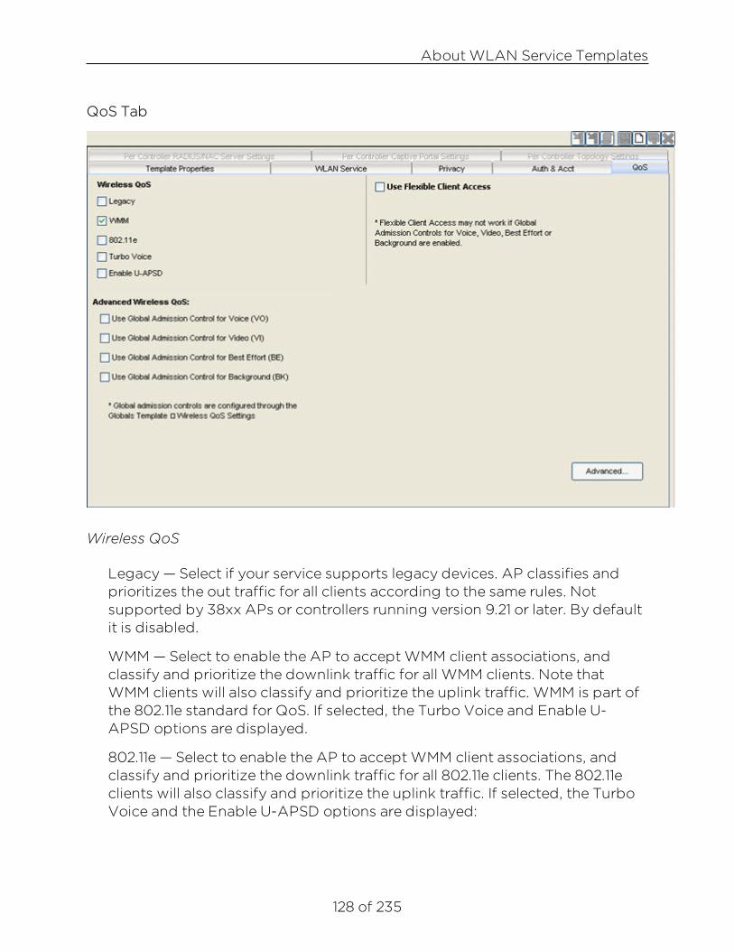
About WLAN Service Templates
128 of 235
QoS Tab
Wireless QoS
Legacy — Select if your service supports legacy devices. AP classifies andprioritizes the out traffic for all clients according to the same rules. Notsupported by 38xx APs or controllers running version 9.21 or later. By defaultit is disabled.
WMM — Select to enable the AP to accept WMM client associations, andclassify and prioritize the downlink traffic for all WMM clients. Note thatWMM clients will also classify and prioritize the uplink traffic. WMM is part ofthe 802.11e standard for QoS. If selected, the Turbo Voice and Enable U-APSD options are displayed.
802.11e — Select to enable the AP to accept WMM client associations, andclassify and prioritize the downlink traffic for all 802.11e clients. The 802.11eclients will also classify and prioritize the uplink traffic. If selected, the TurboVoice and the Enable U-APSD options are displayed:

About WLAN Service Templates
129 of 235
l Turbo Voice — Select to enable all downlink traffic that is classified to theVoice (VO) AC and belongs to that VNS to be transmitted by the AP via aqueue called Turbo Voice (TVO) instead of the normal Voice (VO) queue.When Turbo Voice is enabled together with WMM or 802.11e, the WMMand/or 802.11e clients in that VNS are instructed by the AP to transmit alltraffic classified to VO AC with special contention parameters tailored tomaximize voice performance and capacity. Not supported by 38xx APs.
l Enable U-APSD — Select to enable the Unscheduled Automatic PowerSave Delivery (U-APSD) feature. This feature can be used by mobiledevices to efficiently sustain one or more real-time streams while being inpower-save mode. This feature works in conjunction with WMM and/or802.11e, and it is automatically disabled if both WMM and 802.11e aredisabled.
Use Flexible Client Access
Click to enable flexible client access.
AdvancedWireless QoS
(VO) — Select to enable Global Admission Control for Voice.
(VI) — Select to enable Global Admission Control for Video.
(BE) — Select to enable Global Admission Control for Best Effort.
(BK) — Select to enable Global Admission Control for Background.
Advanced Button
Click the Advanced button to open a window where you can configureadvanced QoS settings. For more information, see Advanced QoS SettingsWindow.
Per Controller RADIUS/NAC Server Settings TabIdentifies the NAC and RADIUS settings specific to a particular WirelessController. This tab is available once a template has been deployed.
Per Controller Captive Portal Settings TabIdentifies the captive portal settings specific to a particular WirelessController. This tab is available once a template has been deployed.
About WLAN Service Templates
130 of 235
Per Controller Topology Settings TabIdentifies the topology settings specific to a particular Wireless Controller.This tab is available once a template has been deployed.
Cloning an Existing WLAN Service
To create a WLAN Service template by cloning an existing template orconfiguration:
1. Click the Templates tab.
2. In the left pane, click New, expand Clone, and click Clone WLAN Service.The Clone WLAN Service wizard launches.
3. On the Cloning Source dialog, in the New template name field, enter aname for the new WLAN Service.
4. Select one of the following:
l Base template on a deployed WLAN Service – This option lets youcreate a template by copying the settings of a WLAN Servicedeployed on a Wireless Controller.
l Base template on an existing WLAN Service – This option lets youcreate a template by copying a template that already exists on theWireless Controller.
5. The window that lists the selected item becomes active. Click the ViewSelected button to view detailed information about the cloning source.
6. Click Next.
7. The Cloning Summary page displays the WLAN Service configuration thatyou selected. Click Finish to clone the WLAN Service or Cancel to discard it.
Viewing Summary Information About All WLAN ServicesTemplatesYou can view summary information about WLAN Services currently defined inWireless Manager from the WLAN Services Summary page. From this page, youcan also perform the following tasks:
l Deploy or undeploy the template.
l Edit, clone, or delete an existing WLAN Service definition.
l Export a WLAN Service configuration to the CLI.
l Create new WLAN Service definition.

About WLAN Service Templates
131 of 235
To view information about configured WLAN Services:
1. Click the Templates tab.
2. In left-hand pane, click WLAN Services. The WLAN Services TemplateSummary page displays.
The following list describes the information available on the WLAN Servicespage.
StatusStatus of this WLAN Service. Options include:
Deployed, Not Deployed, Deployed but not synchronized to thenetwork,
Deployed but some templates not synchronized.
NameName assigned to the WLAN Service.
EnabledWhether the WLAN Service created from this template will be deployed inthe enabled or disabled state. Options are: enabled or disabled.
TypeType of WLAN Service.

About WLAN Service Templates
132 of 235
SSIDService Set Identifier (SSID) is the name of a wireless local area network(WLAN).
AuthAuthentication mode assigned to this WLAN Service.
PrivacyPrivacy settings for this WLAN Service.
ControllersWireless Controller to which this WLAN Service has been deployed.
Toolbar ButtonsFor a description of common toolbar buttons see Context-Sensitive Toolbar.
Related Informationl Deleting Templates
l Editing Templates
l Viewing Detailed Template Information

133 of 235
Advanced QoS Settings Window
Use this window to configure advanced WLAN Service QoS settings. To accessthis window, click the Advanced button in the QoS Tab.
Priority ProcessingClick Priority Override to force a service class and DSCP marking. Whenenabled, the configured service class forces queue selection in the downlinkdirection, the 802.11P user priority for the VLAN tagged Ethernet packets andthe user priority for the wireless QoS packets (WMM or 802.11e), according tothe mapping between service class and user priority.
Service ClassFrom the drop-down list, click the appropriate priority level:
l Network control (7) - highest priority level
l Premium (Voice) (6)
l Platinum (5)
l Gold (4)
l Silver (3)
l Bronze (2)

About WLAN Service Templates
134 of 235
l Best Effort (1)
l Background (0) - lowest priority level
DSCP markingFrom the drop-down list, click the DSCP value used to tag the IP header ofthe encapsulated packets.
Related Informationl About WLAN Service Template

135 of 235
Advanced WLAN Service Settings Window
Use this window to configure advanced WLAN Service Template settings. Toaccess this window, click the Advanced button in the WLAN Service Tab.

About WLAN Service Templates
136 of 235

About WLAN Service Templates
137 of 235
TimeoutIdle (pre)
Specify the amount of time in minutes that a mobile user can have a sessionon the Wireless Controller in pre-authenticated state with no active traffic.The session will be terminated if no active traffic is passed within this time.The default value is 5 minutes.
Idle (post)Specify the amount of time in minutes that a mobile user can have a sessionon the Wireless Controller in authenticated state with no active traffic. Thesession will be terminated if no active traffic is passed within this time. Thedefault value is 30 minutes.
SessionSpecify the maximum number of minutes of service to be provided to theuser before termination of the session.
RFSuppress SSID
Select to prevent this SSID from appearing in the beacon message sent bythe Wireless AP. The wireless device user seeking network access will not seethis SSID as an available choice, and will need to specify it.
Enable 11h supportSelect to enable TPC (Transmission Power Control) reports. By default thisoption is disabled. It is recommended that you enable this option.
Process client IE requestsSelect to enable the Wireless AP to accept IE requests sent by clients viaProbe Request frames and responds by including the requested IEs in thecorresponding Probe Response frames. By default this option is disabled. It isrecommended that you enable this option.
Energy Save ModeSelect to reduce the number of beacons the AP transmits on a BSSID whenno client is associated with the BSSID. This reduces both the powerconsumption of the AP and the interference created by the AP when noclient is associated.
Radio Management (11k) supportSelect to enable radio management, which optimizes network performanceby allowing a client to select an AP based on the number of activesubscribers and overall traffic.

About WLAN Service Templates
138 of 235
Beacon ReportSelect to transmit a request frame from the AP to a client to request it reporton beacons it has heard on all channels.
Quiet IESelect to set a period of time where no transmission occurs on the currentchannel to assist in making measurements without interference.
Egress Filtering ModeEnforce explicitly defined "Out" rules
When egress filtering mode is set to enforce explicitly defined "Out" rules, allWLAN services will enforce outbound filters on egress traffic, exactly as theyare defined in the role.
Apply "In" rules to "Out" direction trafficWhen egress filtering mode is set to apply "In" filter rules to "Out" directiontraffic, all WLAN services will enforce that any outbound filter rules explicitlydefined in the role are overridden by a set of rules created by copying eachinbound filter rule and swapping the source and destination address roles inthe rule. When "In" filter rules are applied to "Out" traffic, the role of thesource and destination address are reversed.
Client BehaviorBlock MU to MU traffic
Select the checkbox if you want to prevent two devices associated with thisSSID and registered as users of the Wireless Controller, to be able to talk toeach other. The blocking is enforced at the L2 (device) classification level.
Remote ServiceRemotable
Select the checkbox if you want to make this service remotable.
Inter-WLAN Service RoamingPermit Inter-WLAN Service Roaming
Select the checkbox to permit inter-WLAN service roaming.
Unauthenticated BehaviorDiscard Unauthenticated Traffic
Select to drop all traffic flowing to and from an unauthenticated station.Cannot be used if any form of captive portal is the only form of authenticationfor the WLAN.

About WLAN Service Templates
139 of 235
Default Non-Authenticated PolicySelect to apply the default non-authenticated policy to all traffic flowing toand from an unauthenticated station.
Related Informationl About WLAN Service Template

140 of 235
Settings Window
This window lets you define the authentication mode settings for your WLANService templates. The settings in this window vary depending on theauthentication mode you have selected for your template.
To access this window, select your authentication mode and then click theConfigure button in the Add WLAN Service's Auth & Acct tab.
This Help topic provides information on configuring settings for the followingauthentication modes:
l Internal/Guest Portal/Guest Splash
l 802.1x with HTTP Redirection/External
l Firewall Friendly External Captive Portal
Internal/Guest Portal/Guest Splash
This section presents definitions for the various settings that can be configuredfor the Internal, Guest Portal, and Guest Splash authentication modes. Settingsused by the different modes will vary.
Internal Authentication Mode Dialog
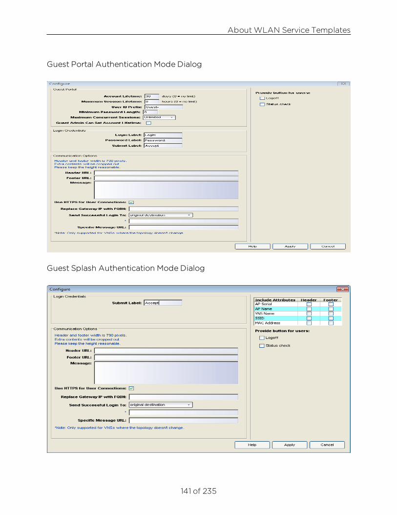
About WLAN Service Templates
141 of 235
Guest Portal Authentication Mode Dialog
Guest Splash Authentication Mode Dialog

About WLAN Service Templates
142 of 235
This section is only displayed for Guest Portal authentication mode.
Account LifetimeSpecify the number of days that a guest account will be active. A value of 0specifies no limit to the account lifetime.
Maximum Session LifetimeSpecify the maximum number of hours that a guest session can be active.The default value of 0 does not limit the session lifetime. The session lifetimeis the allowed cumulative total in hours spent on the network during theaccount lifetime.
User ID PrefixEnter a prefix that will be added to all guest account user IDs. The default isGuest.
Minimum Password LengthEnter a minimum password length that will be applied to all guest accounts.The default is eight characters.
Maximum Concurrent SessionsSpecify the maximum number of concurrent guest sessions allowed. Thedefault is unlimited.
Guest Admin Can Set Account LifetimeSelect this checkbox to allow the guest administrator to set the amount oftime that this account will be active.
Login Credentials
Specify the wording that will be used for the fields in the Captive Portal wherethe end user will enter their login credentials.
Login LabelThis label defines the field where the end user enters their user name.
Password LabelThis label defines the field where the end user enters their password.
Submit LabelThis label will be displayed as the text for the button to submit credentials.
Communication OptionsHeader URL
Enter the server location of the file to be displayed in the Header portion ofthe Captive Portal page. This page can be customized with logos or other

About WLAN Service Templates
143 of 235
graphics to suit your organization.
Footer URLEnter the server location of the file to be displayed in the Footer portion of theCaptive Portal page.
CAUTION: If you use logos or graphics, make sure they are appropriately sized. Largelogos or graphics may force the login section on the Captive Portal out of view.
MessageEnter the message that will be displayed above the Login box to greet theuser. For example, the message could explain why the Captive Portal page isappearing, and provide instructions for the user. The message can be amaximum of 255 characters, including spaces.
Use HTTPS for User ConnectionsSelect this checkbox to force Captive Portal web pages to be served securelyover HTTPS (instead of HTTP) to end users on the network. Deselect thisoption to allow the Captive Portal to be accessed without requiring HTTPsand certificates.
Replace Gateway IP with FQDNSpecify the gateway's FQDN (Fully Qualified Domain Name) to use insteadof the IP address.
Send Successful Login ToThere are three Redirection options that specify where the end user isredirected following successful authentication, when the end user is allowedon the network:
l Original destination - If the WLAN Service is configured to send successfullogins to the “original destination” and the ECP does not return the originaldestination then the station will be redirected to an error page.
l Captive Portal session page - This option lets you specify the URL for theCaptive Portal session page.
l Custom specific URL - This option lets you specify the URL for the webpage where the end user will be redirected.This would most likely be thehome page for the enterprise website, for example,"http://www.ExtremeNetworks.com."
Specific Message URLEnter the URL of a document that will be displayed in a text frame on theCaptive Portal login page. This text frame can be used to display lengthier
About WLAN Service Templates
144 of 235
messages, such as terms and conditions of use for users who have not yetlogged in.
Include Attributes
If applicable, select the appropriate checkboxes in both the Header and Footercolumns to include the following attributes in the message to the authenticationserver:
l AP Serial
l AP Name
l VNS Name
l SSID
l MAC Address
The selections influence what URL is returned in either section. For example,wireless users can be identified by which Wireless AP or which VNS they areassociated with, and can be presented with a Captive Portal web page that iscustomized for those identifiers.
Provide button for usersLogoff
Select the Logoff checkbox to provide users with a Logoff button thatlaunches a pop-up logoff page, allowing users to control their logoff. Whenthe user clicks the Logoff button, the user is disassociated and returns to thenon-authenticated state.
Status CheckSelect the Status check checkbox to provide users with a Status check buttonthat launches a pop-up window, allowing users to monitor session statisticssuch as system usage and time left in a session.
802.1x with HTTP Redirection/External
This section presents definitions for the various settings that can be configuredfor the 802.1x with HTTP Redirection and External authentication modes.

About WLAN Service Templates
145 of 235
Session Control InterfaceController Connection
External authentication server access. Port range: 32768 - 65535. For eachtarget controller, during deployment you will be prompted to specify the IPaddress of one of its physical/admin topologies and port. If there is anauthentication server configured for this WLAN, the external Captive Portalpage on the external authentication server will send the request back to theIdentiFi Wireless Appliance to allow the appliance to continue with theRADIUS authentication and filtering.
Enable HTTPS supportSelect this checkbox if you want to enable HTTPS support (TLS/SSL) for thisexternal captive portal.
EncryptionSelect the data encryption to use. Options are: None, Legacy, and AES.
Shared SecretIf you want to encrypt the information passed between the IdentiFi WirelessAppliance and the external web server, enter the password common to boththe appliance and the server.
Redirection URLEnter the URL that the wireless device user will be directed to afterauthentication.
NOTE:The Redirection URL does not support IPv6.

About WLAN Service Templates
146 of 235
Add Controller IP & Port to redirection URLSelect the checkbox to enable redirection.
SpecialToS Override for NAC
Select this checkbox to allow ToS marking results in redirection to a captiveportal via a NAC server.
Firewall Friendly External Captive Portal
This section presents definitions for the various settings that can be configuredfor Firewall Friendly External Captive Portal authentication mode. The settingswindow for the Firewall Friendly External Captive Portal mode is shown below.
Redirect to External Captive PortalIdentity and Shared Secret
Identity and shared secret are optional. They must be provided if the ECP isgoing to sign its redirection responses and wants the controller to sign itsredirection responses. The identity must be a printable (non-control code)

About WLAN Service Templates
147 of 235
ASCII alphanumeric string. The shared secret should be a printable (non-control code) ASCII string. It should have a length of between 16 and 255characters. It can contain slashes, braces and other printable ASCII symbols.As the name “shared secret” implies, exactly the same key must beconfigured on the ECP and associated with the same identity.
These two fields play a crucial role in signature generation. The identity fieldmust be included in any signed redirected web request that redirects a userfrom ECP to the controller or vice versa. The identity tells the receiver whichshared secret to use to validate the message signature.
The identity field and shared secret work together as a pair. Different WLANServices on one controller can have the same identity configured, in whichcase the WLAN Services must have the same shared secret.
Redirection URLThe redirection URL is the URL that stations will have their HTTP trafficredirected to. This is a mandatory field and should point to a page, script orprogram served by the ECP. Both HTTP and HTTPS are supported.
The redirection URL will have some parameters appended to it when it isreceived by the ECP. All information communicated with the ECP will be partof the redirection URL query string. The minimum information included in theURL are a token, a WLAN identifier and the original URL that the station wastrying to access when it was redirected to the ECP.
l The token is an identifier for the user-session. It must be included as aquery string parameter in all ECP redirections back to the controller.
l The WLAN identifier helps the controller determine how to process theredirect back from the ECP. It must be included in the redirection sent bythe ECP to the controller’s web server.
l The original URL that the station was trying to access when it wasredirected may or may not be important. If the administrator wants allauthenticated users to end the login sequence on one specific page (suchas the site’s news page) then the original URL can be ignored by the ECP. Ifthe administrator wants the user to be redirected to a session managementpage after a successful login or if he wants the user to be sent to theoriginal URL then the ECP must save the original URL and include it in theredirection that causes the user’s browser to return back to the controller.
NOTE:The following (optional) attributes can be sent by the Controller to the ECP viaBrowser Redirection.

About WLAN Service Templates
148 of 235
EWC IP & PortSelect this checkbox to include the controller’s address on the topology(VLAN) to which the user is assigned. The controller can include its IPaddress and port in the redirection URL. This is optional, but necessary if theECP interacts with more than one controller. Without these fields the ECPmay not be able to compose the correct redirection URL to cause a station tocomplete authentication on the correct controller. Only IPv4 addresses aresupported.
Unlike standard ECP, the administrator does not directly configure thecontroller IP address and port to which the ECP should redirect stations.Standard ECP makes use of a separate connection that is used by the ECP tosend session control messages to the controller. FF-ECP does not have thisconnection because control messages are relayed from the ECP to thecontroller via redirecting the station’s browser.
Since the station’s browser conveys the commands to the controller thestation must have easy access to the controller interface and port that willreceive the redirection. This will be the controller’s address on the topology(VLAN) to which the user is assigned. The address to use is only known oncea VNS based on the WLAN Service is fully configured.
Replace EWC IP with EWC FQDNSometimes it is convenient for the ECP to be able to redirect stations back toan FQDN belonging to a controller. This is necessary to avoid certificatewarnings when the certificate contains FQDNs for identity instead of IPaddresses. The “EWC IP and Port” option normally adds the IP address andport on the controller that the ECP should redirect clients to. If “EWC IP andPort” is enabled and the FQDN field is populated with a valid FQDN thecontroller will put the provided FQDN and port into the redirection it sends tothe station. This option only takes effect when the “EWC IP and Port” optionis enabled.
AP name & serial numberSelect this checkbox to include the name and serial number of the APassociated with this station. Can be useful if the ECP needs to behavedifferently depending on the location of the station being authenticated.
Associated BSSIDSelect this checkbox to include the Basic Service Set Identifier (BSSID) towhich the station being authenticated has associated. It is the MAC addressbelonging to the AP to which the station has associated. The BSSID is thesame identifier that the controller puts in the Called-Station-ID RADIUS TLVsent in Access-Requests and RADIUS accounting messages. The associated

About WLAN Service Templates
149 of 235
BSSID will be sent in the form of a 12 character ASCII-encoded lowercase hexstring, for example: "00112233aabb”.
VNS NameSelect this checkbox to include the name of the VNS associated with theSSID.
SSIDSelect this checkbox to include the SSID that identifies the WLAN service forthe wireless controller.
Station's MAC AddressThis attribute uniquely and globally identifies the station. More specifically,this is the MAC address of the station’s wireless interface that associated tothe BSSID. This holds the same value that the controller puts in the Calling-Station-Id RADIUS attribute. The station MAC address will be sent in the formof a 12 character ASCII-encoded lowercase hex string, for example:“00112233aabb”.
Currently assigned roleThis attribute contains the name of the access control role assigned to thestation at the time its browser was redirected to the ECP. The contents of thisattribute match the contents of the Siemens RADIUS VSA called “Siemens-Policy-Name”.
Containment VLAN (if any) of assigned roleIf the default action of the Currently Assigned Role is “Contain to VLAN” thenthis contains the name of the topology/VLAN to which the station’s traffic iscontained by default. Roles need not have a Contain to VLAN default action,in which case this attribute would be empty, even if requested.
TimestampSelect this checkbox to include the time on the controller (in UTC secondselapsed since 1970-01-01 00:00:00) at which the HTTP request that wasredirected to the ECP was received. The timestamp will be included if thecontroller is configured to sign the redirection to the ECP, even if it was notexplicitly requested. The timestamp is useful for preventing replay attacks ofrecorded redirected requests.
SignatureSelect this checkbox to have the controller compute a secure hash overportions of the redirection response. Even if not explicitly requested, theresponse will include a timestamp. Requires the user to configure SharedSecret and Identity properties.

About WLAN Service Templates
150 of 235
The identity will be included in the redirect to the ECP. The ECP can use thisto look up the appropriate shared secret in order to validate the signature.
Selecting the timestamp and signature options does not cause the controllerto expect signatures on the redirects from the ECP. However if a WLANService that uses FF-ECP is not configured with at least one RADIUSauthentication server then the redirections from the FF-ECP to the controllermust be signed and time stamped.
Redirect From External Captive PortalUse HTTPS for User Connections
This setting controls whether the controller listens for redirects at port 443 orport 80 and whether it expects to receive redirects from the ECP as HTTPS orHTTP.
The default is to use HTTPS. This is the most secure option. The controller hasa self-signed certificate that it will use by default for HTTPS. However, mostbrowsers will immediately warn the user that they are being redirected to asite with a self-signed certificate. If this service is to be used by large numbersof users or by casual users it is best to obtain a certificate from a CA that istrusted by all browser vendors. An administrator running multiple controllerswith FF-ECP can obtain a wildcard certificate that covers all the interfaces ofall the controllers.
If a third party certificate is installed, it must be installed on the topology thatstations have direct access to (typically either the WLAN Service’s defaulttopology/VLAN or the station’s role’s default action’s containment VLAN).
Send Successful Login ToThere are three Redirection options that specify where the end user isredirected following successful authentication, when the end user is allowedon the network:
l Original destination - This option redirects the end user to the web pagethey originally requested when they connected to the network. If theWLAN Service is configured to send successful logins to the “originaldestination” and the ECP does not return the original destination then thestation will be redirected to an error page.
l Captive Portal session page - This page contains controls to tell how longthe user’s session has lasted and to gracefully terminate the user’s session.It can also contain a link to the original URL the browser was trying toreceive when it was redirected. The “original URL” option will only work ifthe ECP sends to the controller the original URL (“dest” parameter) that the

About WLAN Service Templates
151 of 235
controller sent to the ECP in the initial redirect. If the ECP does not returnthe original destination URL in the redirect to the controller and the WLANService is configured to redirect the station to “Captive Portal SessionPage” the user will be redirected to that page, but it will not contain a linkto the original destination.
l Custom specific URL - This option lets you specify the URL for the webpage where the end user will be redirected.This would most likely be thehome page for the enterprise website, for example,"http://www.ExtremeNetworks.com."
Related Informationl About WLAN Service Template

152 of 235
About Role Templates
A Role defines the binding of a topology (VLAN), Class of Service, and filterrules that should be applied to the traffic of a station. Roles don't need to befully specified; unspecified attributes are retained by the user or inherited fromthe Global Role definitions on the Wireless Controller.
This Help topic includes the following information:
l Creating a Role Configuration Template
l Migrating Legacy Role Templates
l Using Policy Manager to Create Role Templates
l Viewing Roles Summary Information
l Viewing Detail Information About a Role
l Viewing Legacy Summary Information
l Viewing Detail Information About a Legacy Role
Creating a Role Configuration TemplateWireless Manager no longer supports the configuration of Roles (see LegacyTemplate Migration Notice).
Migrating Legacy Role TemplatesIf you have any legacy Role templates, they must be migrated within 30 daysotherwise support will be terminated.
To migrate existing Role Templates:
1. Deploy your templates to the managed wireless controllers.
2. Using Policy Manager, assign your wireless controllers to a Policy domainand import their configuration. Select File > Import > Policy Configurationfrom Device.
3. From the Import from Device wizard, you must specify whether to importroles, rules, and/or Class of Services.
4. Save your changes.

About Role Templates
153 of 235
5. Modify your Wireless Manager templates as needed to reference the newlycreated Role and CoS templates automatically imported from PolicyManager.
6. Remove the legacy templates.
l You can either delete the templates one-by-one or for your convenienceuse the following buttons displayed in the Legacy Template Migrationdialog:
l Brute-Force Cleanup – Deletes all legacy templates whether or notthey are referenced by other templates. VNS templates may become"Incomplete".
l Best-Effort Cleanup – Deletes all legacy templates not referenced byother templates.
l If "Brute-Force Cleanup" results in a VNS becoming "Incomplete", it will bedisplayed in the Conflict Resolution wizard as a reminder for you tocomplete its definition and to specify a Non-Authenticated role for it.
l Please note these cleanup operations will even remove the legacypredefined CoS: Scavenger, Best Effort, Bulk Data, Critical Data, NetworkControl, Network Management, RTP/Voice/Video, and High Priority.However, upon synchronization with Policy Manager they will beautomatically re-created, and will be consistent with their Policy Managercounterparts.
Using Policy Manager to Create Role TemplatesIf you are using Policy Manager, after you save the configuration for a particulardomain that includes Wireless Controllers, Wireless Manager will automaticallycreate for you those Roles defined in the domain. Since a Role in Policy Managercan have different definitions in different domains, in Wireless Manager theNavigation Tree shows a single Role, which when clicked, displays a separatetab for each domain specific version of the Role.
Roles created on behalf of Policy Manager follow these guidelines:
l PM-Roles are located under the Templates tab > Roles > Roles section ofthe Navigation Tree. Roles created using Wireless Manager, either manuallyor by cloning an existing Role Template or deployed Role, are locatedunder the Templates tab > Roles > Roles > Legacy.

About Role Templates
154 of 235
l PM-Roles can be easily identified in drop down lists (for example, forselection in a VNS) since their names include the name of the PolicyManager domain from which they were created.
l PM-Roles cannot be edited from within Wireless Manager except forconfiguring their Point of Presence. For more information on Deploying thePoint of Presence Wizard, see Creating, Scheduling, and Deploying Tasks.
l PM-Roles cannot be deleted by the user. A PM-Role will be automaticallydeleted from Wireless Manager when it is either deleted from all thosedomains (with assigned Wireless Controllers) where it is defined, or all theWireless Controllers are removed from those domains where it is defined. Ifa PM-Role exists in multiple domains, and instead the Role is deleted fromjust one domain (with assigned Wireless Controllers) where it is defined, orall the Wireless Controllers are removed from that domain, then thecorresponding domain specific version of that Role is deleted fromWireless Manager. If the domain specific version of the PM-Role was beingreferenced by a VNS template, then that template is marked "Incomplete"and must be completed before it can be deployed.
l PM-Roles are not deployable by themselves, but can be referenced in thedeployment of VNS. During the deployment of a VNS template referencingPM-roles, the user can now select the option 'Enforce using PolicyManager' to have Wireless Manager trigger Policy Manager to enforce thedomain configuration on any target controllers referenced by thedeployment task. If this option is not selected, Wireless Manager willassume that these PM-roles already exist on the target Wireless Controllers.In general this is a valid assumption since the user, most likely, has alreadyused Policy Manager to "Enforce Role Set" for the domain where theseWireless Controllers reside. In the unlikely scenario these PM-roles don't yetexist on the target Wireless Controllers, Wireless Manager will fail thedeployment with a suitable error message, and you can correct theproblem from Wireless Manager by selecting the option 'Enforce usingPolicy Manager' during deployment or from Policy Manager using "EnforceRole Set".
l The Status for these PM-Roles are blank. PM-Roles are not audited byWireless Manager. Instead, Policy Manager detects and reports anydiscrepancies between the current Role set of a domain and the Rolesdefined on the Wireless Controllers in the domain. Wireless Managerhowever, will verify that a VNS is referencing the correct PM-Roles on thetarget Wireless Controllers.

About Role Templates
155 of 235
For more information about how to create Roles in Policy Manager, refer to theNetSight Policy Manager User Guide.
Viewing Roles Summary InformationYou can view summary information about PM-Roles currently defined inWireless Manager from the Summary for PM-Roles page. From this page, youcan see at a glance the set of Policy Manager domains where a particular PM-Role is defined.
To view summary information for PM-Roles:
1. Click the Templates tab.
2. In left-hand pane, click Roles and select the Roles folder. The Summary forRoles page displays the Policy domains for each Role.
Viewing Detail Information About a RoleTo view information about a configured Role:

About Role Templates
156 of 235
1. Click the Templates tab.
2. In left-hand pane, click Roles. Expand the Roles folder and select a Role.The Roles Details page displays.
NOTE:PM roles can have different definitions in different domains.
The following list describes the information available on the Roles Details page.
Default Policy Domain TabEnforced Name
Name of this Role if it were deployed to a Wireless Controller in that domain.
DomainDomain name.
Controller(s) in DomainIP addresses of all those controllers assigned to the specified Policy Managerdomain.

About Role Templates
157 of 235
General TabPlease refer to the Policy Manager User Guide for information.
Rules TabRead-only view of the policy rules assigned to the role, with links toreferenced PM CoS and/or PM topologies. Please refer to the Policy ManagerUser Guide for information.
VLAN Egress TabRead-only view of the Egress VLANs assigned to the role with links toreferenced PM topologies. Please refer to the Policy Manager User Guide forinformation.
Viewing Legacy Summary InformationWireless Manager no longer supports the configuration of Roles (see LegacyTemplate Migration Notice).
To view information about configured Legacy Roles:
1. Click the Templates tab.
2. In left-hand pane, click Roles. Expand the Roles folder and select Legacy.The Summary for Legacy Roles page displays.

About Role Templates
158 of 235
The following list describes the information available on the Summary for LegacyRoles page.
StatusStatus of this Role. Options include:
Deployed, Not Deployed, Deployed but not synchronized to thenetwork
Deployed but some templates not synchronized.
NameName assigned to this Role.
TopologyTopology assigned to this Role.
Class of ServiceClass of Service assigned to this Role.
ModeThe mode of operation of the topology assigned to this Role. Values are:Routed, B@AP, or B@EWC.

About Role Templates
159 of 235
Filter DefinedIndicates whether AP Filtering or Custom AP Filtering is enabled.
ControllersList of Wireless Controllers to which this Role is deployed.
Toolbar ButtonsFor a description of common toolbar buttons see Context-Sensitive Toolbar.
Viewing Detail Information About a Legacy RoleWireless Manager no longer supports the configuration of Roles (see LegacyTemplate Migration Notice).
To view information about a Legacy Role:
1. Click the Templates tab.
2. In left-hand pane, click Roles. Expand the Roles folder and select a LegacyRole. The Legacy Role Details page displays with the Template Propertiestab active. For more information about the fields on this tab, see theTemplate Properties Tab Help topic.
The following sections describe the information available on the Role TemplateConfiguration tabs.
VLAN and Class of Service TabName
Name of this Role.
Assigned TopologySelect a Topology to assign to this Role from the list.
Default Class of ServiceSelect the Class of Service to assign to this Role. Options include:
l no change - The Class of Service of the prior Role Template is used.
l No CoS - No rate limiting, no TXQ assignment, no Marking.
l Predefined CoS for PM: Scavenger, Best Effort, Bulk Data, Critical Data,Network Control, Network Management, RTP/Voice/Video, High Priority.
l Classes of Service listed alphabetically.
Filters Rules TabEnable AP Filtering
Select the checkbox to enable filtering on the APs.

About Role Templates
160 of 235
Inherit filter rulesSelect the checkbox to inherit filter rules from currently applied Role.
RuleOptions include:
l U – The filter has user-defined rules
l D – The default filter
InIdentifies the rule that applies to incoming traffic. You can change this settingusing the drop-down menu. Options include: Destination (dest), Source(src), None, and Both.
OutIdentifies the rule that applies to outgoing traffic. You can change this settingusing the drop-down menu. Options include: Destination (dest), Source(src), None, and Both.
IP:PortThe IP address and port on the Wireless Controller or AP to which this filterapplies.
ProtocolThe protocol to which this filter applies.
PriorityThis is the 802.1p value of this filter.
ToS/DSCPThis is the ToS/DSCP marking value of this filter.
AccessAllow or Deny access.
CoSThis is the Class of Service assigned to this filter.
UpClick to move the selected filter up in the list.
DownClick to move the selected filter down in the list.
AddClick to add a new filter rule. The following fields appear in the Add Filterdialog:
Direction

About Role Templates
161 of 235
In Filter - Options include: Destination (dest), Source (src), None, and Both.
Out Filter - Same options as the In Filter except it refers to outgoing traffic.
Classification
IP/Subnet: The IP address and subnet to which this filter applies.
Port: Port designation on the IP address.
Protocol: In the Protocol drop-down list, click the applicable protocol. Thedefault is N/A.
ToS/DSCP Marking
Priority
Action
Access Control
Class of Service
OK: Click to add the filter rule to the filter group. The information displays inthe filter rule table.
Cancel: Click to discard your changes.
EditClick to edit the selected filter.
DeleteClick to remove the selected filter from the list.
Per Controller Settings TabAssigned Topology
Includes a link to the Topology assigned to this Role, so that you can view itsper-Wireless Controller customizations.

162 of 235
About Rate Profiles
A rate profile can limit the maximum amount of throughput that is available to astation. See Legacy Template Migration Notice.
This Help topic includes the following information:
l Viewing Summary Information About All Rate Profiles
l Viewing Detail Information About a Rate Profile
Viewing Summary Information About All Rate ProfilesYou can view summary information about rate profile configurations currentlydefined in Wireless Manager by accessing the Rate Profile Summary page. Fromthis page, you can also perform the following tasks:
l Edit, clone, or delete an existing rate profiles definition.
l Create tasks to deploy a rate profile.
l Export an rate profile configuration to the CLI.
l Create new rate profile definition.
To view information about configured rate profiles:
1. Click the Templates tab.
2. In left-hand pane, click Roles, and then click Rate Profiles. The Rate ProfilesSummary page displays.

About Rate Profiles
163 of 235
The following list describes the information available on the Rate ProfileSummary page.
StatusOptions include:
Deployed, Not Deployed, Deployed but not synchronized to thenetwork
NameName assigned to this rate profile.
Average Rate (Kbps)Data transfer rate in Kbps assigned to this rate profile.
Used by PolicyPolicies that use this rate profile.
ControllersWireless Controllers that use this rate profile.
Toolbar ButtonsFor a description of common toolbar buttons see Context-Sensitive Toolbar.
Viewing Detail Information About a Rate ProfileTo view information about a Rate Profile:

About Rate Profiles
164 of 235
1. Click the Templates tab.
2. In left-hand pane, click Roles. Expand the Rate Profiles folder and select aRate Profile. The Rate Profiles Details page displays with the TemplateProperties tab active. For more information about the fields on this tab, seethe Template Properties Tab Help topic.
3. Click on the Rate Profile Properties tab to view read-only properties for theProfile.

165 of 235
About AP Profiles
An AP Profile is a template that contains a set of AP configuration attributes.You can assign an AP Profile to one or more APs in your network.
This Help topic includes the following information:
l Creating an AP Profile Template
l Viewing Summary Information About All AP Profiles
Creating an AP Profile TemplateYou can create an AP Profile template either manually, or by cloning an existingtemplate or an AP configuration. You can also assign an AP Profile to a WirelessController as one of its default AP Profiles. (A Wireless Controller has one defaultAP Profile for each family of compatible hardware types.)
Manually Creating an AP Profile
To manually create an AP Profile template or configuration:
1. Click the Templates tab.
2. In the left pane, click New, expand the New folder and click Add AP Profile.
3. The Access Point Configuration page displays with the TemplateProperties tab active.

About AP Profiles
166 of 235
4. Enter a name for the new template. Enter a template description, if desired.For more information about the fields on this tab, see the TemplateProperties Tab Help topic.
5. Click on the Wireless Radio Settings tab.
6. Select the AP Profile Type. Options include: ABG capable, ABGN capable,Dual Band ABG capable, RoamAbout APs (thin mode), AP37xx W78xC,AP38xx, and AP3801.
7. Select the Regulatory Domain. This is the geographic location where theAP will operate. In general, for a template to be deployed successfully, theregulatory domain in the template must match the regulatory domain in theWireless Controller’s license.
8. Select the Hardware Type. Options change depending on the AP ProfileType selected. For APs with an external antenna in the hardware type,professional installation is enabled.
9. Use the AP Properties and Radio Settings sub-tabs to configure additionalsettings. The two tabs are described below.
About AP Profiles
167 of 235
AP Properties TabLocation
Defines the Location of the Wireless AP. Select a new Location or choosefrom any Location already configured in an AP reported by a WirelessController, or in another AP Profile template. The default Location is NoChange. The Location property supports UTF8 encoding and is onlyconfigurable for APs; it is not a property of any AP Default Settings on theWireless Controller.
Policy ZoneDefines the location-based Policy Zone for the specified AP. Multiple APs canand will have the same Policy Zone. Select a new Policy Zone or choose fromany Policy Zone already configured in an AP reported by a WirelessController, or in another AP Profile template. The default Policy Zone is NoChange. The Policy Zone property is only configurable for APs on 8.11+Wireless Controllers; it is not a property of any AP Default Settings on thecontroller.
AP EnvironmentOptions are Indoor and Outdoor.
RoleSelect either Access Point, Sensor, or Do not change. Once the AP isconfigured as a Sensor, the AP is no longer managed by the WirelessController.
CountrySelect the Country of operation within the specified Regulatory Domain forthis AP Profile.
Tunnel MTUEnter a static MTU value, from 600 to 1500. If the wireless software cannotdiscover the MTU size, it enforces the static MTU size. Set the MTU size toallow the source to reduce the packet size and avoid the need to fragmentdata packets in the tunnel.
LACPClick to Enable or Disable Link Aggregation Control Protocol (LACP) for thisAP. LACP allows two or more Ethernet ports to be dynamically aggregated.On AP38xx and AP3801, LACP negotiates the two Ethernet ports into asingle Link Aggregate Group (LAG). When operating as a LAG, by defaultthe AP distributes the uplink traffic between the two Ethernet ports such that
About AP Profiles
168 of 235
all traffic from each radio goes through separate ports. This settings appliesto Wireless Controllers running 9.01 or later.
Ethernet SpeedOptions include: Auto, 10Mbps, and 100Mbps.
Ethernet ModeOptions include: Full-Duplex, Half-Duplex
AP Properties Tab - Professional Install ButtonAntenna Types
Radio 1 and Radio 2 (Left, Middle, and Right) - Select the Antenna Types forthe AP hardware type to which this AP Profile has been restricted.
Radio1 AttenuationSelect an attenuation level from the drop-down list.
Radio2 AttenuationSelect an attenuation level from the drop-down list.
AP Properties Tab - Advanced ButtonPoll Timeout(s)
Type the timeout value, in seconds, for the Wireless AP to re-establish the linkwith the Wireless Controller if it (Wireless AP) does not get an answer to itspolling. The default value is 10 seconds.
Secure TunnelSelect the desired Secure Tunnel mode from the drop-down list:
l Disabled — Secure Tunnel is turned off and no traffic is encrypted. AllSFTP/SSH/TFTP traffic works normally.
l Encrypt control traffic between AP & Controller — An IPSEC tunnel isestablished from the AP to the controller and all SFTP/SSH/TFTP/WASSPcontrol traffic is encrypted. The AP skips the registration andauthentication phases and when selected, the Secure Tunnel Lifetimefeature can be configured.
l Encrypt control and data traffic between AP & Controller — This mode onlybenefits routed/bridged@AP Topologies. An IPSEC tunnel is establishedfrom the AP to the controller and all SFTP/SSH/TFTP/WASSP control anddata traffic is encrypted. The AP skips the registration and authenticationphases, and when selected, the Secure Tunnel Lifetime feature can beconfigured.
l Debug mode — An IPSEC tunnel is established from the AP to thecontroller, no traffic is encrypted, and all SFTP/SSH/TFTP traffic works

About AP Profiles
169 of 235
normally. The AP skips the registration and authentication phases andwhen selected, the Secure Tunnel Lifetime feature can be configured.
NOTE:Changing a Secure Tunnel mode will automatically disconnect and reconnect the AP.
Secure Tunnel Lifetime [hours]Enter an interval (in hours) at which time the keys of the IPSEC tunnel arerenegotiated. Only applies if both the AP and controller are running V8.31 orlater. Default is 0 (hours).
NOTE:Changing the Secure Tunnel Lifetime setting will not cause any AP disruption.
Telnet/SSH AccessClick to enable or disable Telnet / SSH for access to the Wireless AP.
Maintain Client Sessions in Event of Poll FailureSelect this option (if using a bridged at AP VNS) if the Wireless AP shouldremain active if a link loss with the Wireless Controller occurs. This option isenabled by default.
Restart Service without ControllerSelect this option (if using a bridged at AP VNS) to ensure the Wireless AP’sradios continue providing service if the Wireless AP’s connection to theWireless Controller is lost. If this option is enabled, it allows the Wireless APto start a bridged at AP VNS even in the absence of a Wireless Controller.
Use Broadcast for DissociationSelect this option if you want the Wireless AP to use broadcast disassociationwhen disconnecting all clients, instead of disassociating each client one byone. This option is disabled by default.
LLDPSelect to enable or disable the Wireless AP from broadcasting LLDPinformation. This option is disabled by default.
Announcement Interval(s)If LLDP is enabled, type how often the Wireless AP advertises its informationby sending a new LLDP packet. This value is measured in seconds. If thereare no changes to the Wireless AP configuration that impact the LLDPinformation, the Wireless AP sends a new LLDP packet according to thisschedule.
Announcement Delay(s)If LLDP is enabled, type the announcement delay. This value is measured inseconds. If a change to the Wireless AP configuration occurs that impacts the

About AP Profiles
170 of 235
LLDP information, the Wireless AP sends an updated LLDP packet. Theannouncement delay is the length of time that delays the new packetdelivery. The announcement delay helps minimize LLDP packet traffic.
Time to Live(s)The Time to Live value cannot be directly edited. The Time to Live value iscalculated as four times the Announcement Interval value.
IP Multicast AssemblyClick to enable or disable IP Multicast Assembly on this Wireless AP. Ifenabled, the IP Multicast Assembly feature assembles multicast data packetsthat were too large to fit the MTU size of the tunnel and were fragmented inorder to fit the tunnel header. This feature is applicable to AP36xx, AP37xx,and AP38xx models only. This option is disabled by default.
Balanced Channel List PowerWhen selected, the controller will automatically reduce the configured 'MaxTx Power' to the lesser of the configured value or the minimum of the 'Max TxPower' values allowed for the AP (by regulatory compliance) over theselected channel plan. When unselected, the controller will automaticallyreduce the configured 'Max Tx Power' to the lesser of the configured value orthe maximum of the 'Max Tx Power' values allowed for the AP (by regulatorycompliance) over the selected channel plan.
LEDOptions include: Off, WDS Signal Strength, Identify, Normal.
Location-Based ServiceClick to enable or disable location based service on this Wireless AP.Location-based service allows you to use this Wireless AP with an AeroScoutsolution.
Radio Settings TabAdmin Mode
Select On to enable the radio; select Off to disable the radio.
Radio ModeRadio 1 Options are: a, a/n, a/n/ac, n-strict.Radio 2 Options are: b, g, b/g, g/n, b/g/n, n-strict
Channel Width20 MHz Channel bonding is not enabled:— 802.11n clients use the primary channel (20 MHz),— Non-802.11n clients, as well as beacons and multicasts, use the 802.11a/b/gradio protocols.

About AP Profiles
171 of 235
40 MHz Channel bonding is enabled:— 802.11n clients that support the 40 MHz frequency can use 40 MHz, 20MHz, or the 802.11 a/b/g radio protocols.— 802.11n clients that do not support the 40 MHz frequency can use 20MHzor the 802.11 a/b/g radio protocols.— Non-802.11n clients, beacons, and multicasts use the 802.11 a/b/g radioprotocols.
80 MHz Channel bonding is enabled:— 802.11ac clients that support the 80MHz frequency.
Auto — Channel bonding is automatically enabled or disabled, switchingbetween 20MHz and 40MHz, depending on how busy the extension channelis. If the extension channel is busy above a prescribed threshold percentage,which is defined in the 40 MHz Channel Busy Threshold box, channelbonding is disabled.
New Channel Representation20 MHZ channels are identified with the channel number or central frequencyin MHz (for example, channel number 40 is 5200 MHz)
40 MHz channels contain two 20 MHz channels and either can be primarygiven a 40 MHz channel occupying 5180 and 5200 MHz, it can berepresented as 36+ when the primary channel is 5180 or 40- when theprimary channel is 5200
With the introduction of 11ac and support for 80 MHz-wide channels weneeded a better way to identify them. The channel up/down notation may besufficient for 40 MHz channel bonding, but with 80 MHz-wide channels thereare more than two options to select the primary channel.
Channel Representation
Channel 80 MHz Channel Short Notation Long Notation
5180 (5180, 5200, 5220, 5240) 36/80 36: ([5180], 5200, 5220,5240)
5200 36 +1/80 40: (5180, [5200], 5220,5240)
5220 36 +2/80 44: (5180, 5200, [5220],5240)
5240 36 +3/80 48: (5180, 5200, 5220,[5240])
Short Notation is the lowest 20 MHz channel # + 0-based offset of theprimary channel / channel width.

About AP Profiles
172 of 235
Long Notation is the primary channel followed by the centerfrequencies of the contained 20 MHz channels with the primarychannel frequency enclosed in [ ].
RF DomainType a string that uniquely identifies a group of APs that cooperate inmanaging RF channels and transmission power levels. The maximum lengthof the string is 16 characters. The RF Domain is used to identify a group ofWireless APs.
Guard IntervalClick a guard interval, Long or Short, when a 40 MHz channel is used. It isrecommended that you use a short guard interval in small rooms (forexample, a small office space) and a long guard interval in large rooms (forexample, a conference hall).
Channel Plan - Radio 1If ACS is enabled, you can define a channel plan for the Wireless AP. Defininga channel plan allows you to limit which channels are available for use duringan ACS scan. For example, you may want to avoid using specific channelsbecause of low power, regulatory domain or radar interference. Click one ofthe following:
l All channels — ACS scans all channels for an operating channel and returnsboth DFS and non-DFS channels, if available.
l All Non-DFS Channels — ACS scans all non-DFS channels for an operatingchannel. This selection is available when there is at least one DFS channelsupported for the selected country.
Channel Plan - Radio 2If ACS is enabled, you can define a channel plan for the Wireless AP. Defininga channel plan allows you to limit which channels are available for use duringan ACS scan. For example, you may want to avoid using specific channelsbecause of low power, regulatory domain, or radar interference. Click one ofthe following:
l 3 Channel Plan — ACS will scan the following channels: 1, 6, and 11 in NorthAmerica, and 1, 7, and 13 in most other parts of the world.
l 4 Channel Plan — ACS will scan the following channels: 1, 4, 7, and 11 inNorth America, and 1, 5, 9, and 13 in most other parts of the world.
l Auto — ACS will scan the default channel plan channels: 1, 6, and 11 in NorthAmerica, and 1, 5, 9, and 13 in most other parts of the world.

About AP Profiles
173 of 235
Auto Transmit Power ControlSelect to enable ATPC. ATPC automatically adapts transmission powersignals according to the coverage provided by the Wireless APs. After aperiod of time, the system will stabilize itself based on the RF coverage ofyour Wireless APs. The APs should be part of the same RF Domain tofunction properly.
Max Tx PowerClick the maximum Tx power level to which the range of transmit power canbe adjusted. For an AP Profile that is not restricted to a particular hardwaretype, it is recommended that you select 24 dBm to use the entire range ofpotential Tx power.
Min Tx PowerIf ATPC is enabled, click the minimum Tx power level to which the range oftransmit power can be adjusted. It is recommended that you select the lowestvalue available to use the entire range of potential Tx power.
Auto Tx Power Ctrl AdjustIf ATPC is enabled, click the Tx power level that can be used to adjust theATPC power levels that the system has assigned. It is recommended that youuse 0 dBm during your initial configuration. If you have an RF plan thatrecommends Tx power levels for each Wireless AP, compare the actual Txpower levels your system has assigned against the recommended values yourRF plan has provided. Use the Auto Tx Power Ctrl Adjust value to achieve therecommended values.
Antenna SelectionClick the antenna, or antenna combination, you want to configure on thisradio. When you configure the Wireless 802.11n AP to use specific antennas,the transmission power is recalculated; the Current Tx Power Level value forthe radio is automatically adjusted to reflect the recent antenna configuration.It takes approximately 30 seconds for the change to the Current Tx PowerLevel value to be reflected in the ExtremeWireless Wireless Assistant. Also,the radio is reset causing client connections on this radio to be lost.
NOTE:Antenna Selection is not applicable to the AP3605, 4102, or outdoor AP models.
Radio Settings Tab - Professional Install ButtonAntenna Types
Radio 1 and Radio 2 (Left, Middle, and Right) - Select the Antenna Types forthe AP hardware type to which this AP Profile has been restricted.

About AP Profiles
174 of 235
Radio1 AttenuationSelect an attenuation level from the drop-down list.
Radio2 AttenuationSelect an attenuation level from the drop-down list.
Radio Settings Tab - Advanced ButtonDTIM
Type the desired DTIM (Delivery Traffic Indication Message) period — thenumber of beacon intervals between two DTIM beacons. To ensure the bestclient power savings, use a large number. Use a small number to minimizebroadcast and multicast delay. The default value is 5.
Beacon Period (ms)Type the desired time, in milliseconds, between beacon transmissions. Thedefault value is 100 milliseconds.
RTS/CTS (Bytes)Type the packet size threshold, in bytes, above which the packet will bepreceded by an RTS/CTS (Request to Send/Clear to Send) handshake. Thedefault value is 2346, which means all packets are sent without RTS/CTS.Reduce this value only if necessary.
Fragmentation Threshold (Bytes)Type the fragment size threshold, in bytes, above which the packets will befragmented by the Wireless AP prior to transmission. The default value is2346, which means all packets are sent unfragmented. Reduce this value onlyif necessary.
Max% Non-Unicast Traffic per Beacon PeriodEnter the maximum percentage of time that the AP will transmit non-unicastpackets (broadcast and multicast traffic) for each configured Beacon Period.For each non-unicast packet transmitted, the system calculates the airtimeused by each packet and drops all packets that exceed the configuredmaximum percentage. By restricting non-unicast traffic, you limit the impactof broadcasts and multicasts on overall system performance.
Maximum Distance (m)Enter a value from 100 to 15,000 meters that identifies the maximum linkdistance between APs that participate in a WDS. This value ensures that theacknowledgment of communication between APs does not exceed thetimeout value predefined by the 802.11 standard. The default value is 100meters. If the link distance between APs is greater than 100 meters, configure

About AP Profiles
175 of 235
the maximum distance up to 15,000 meters so that the software increases thetimeout value proportionally with the distance between APs.
Optimized Multicast for Power SaveClick to enable the transmission of multicast packets from CABQ using TXOPof 3 msec. (same as video).
Adaptable rate for MulticastClick to enable the multicast transmit rate to be the minimum unicast transmitrate of all clients on the VLAN (topology).
Multicast to Unicast deliveryClick to enable the transmission of multicast traffic as unicast packets forincreased speed.
Dynamic Channel SelectionTo enable Dynamic Channel Selection, click one of the following:
l Monitor Mode — If traffic or noise levels exceed the configured DCSthresholds, an alarm is triggered and an information log is generated.
l Active Mode — If traffic or noise levels exceed the configured DCSthresholds, an alarm is triggered and an information log is generated. Inaddition, the Wireless AP will cease operating on the current channel andACS is employed to automatically select an alternate channel for theWireless AP to operate on.
Minimum Basic RateClick a minimum basic rate: 1 Mbps, 2Mbps, 5.5Mbps, 11Mbps.
DCS Noise ThresholdType the noise interference level, measured in dBm, after which ACS will scanfor a new operating channel for the Wireless AP if the threshold is exceeded.
DCS Channel Occupancy ThresholdType the channel utilization level, measured as a percentage, above whichDynamic Channel Selection will be engaged.
DCS Update PeriodType the time, measured in minutes that determines the period during whichthe Wireless AP averages the DCS Noise Threshold and DCS ChannelOccupancy Threshold measurements. If either one of these thresholds isexceeded, then the Wireless AP will trigger ACS.
Probe SuppressionSuppresses client probing, which causes multiple APs to respondunnecessarily in high-density deployments.

About AP Profiles
176 of 235
Force DisassociateDisassociates clients from an AP when five dBm below the suppressionthreshold. This allows them to automatically reconnect to a better AP.
RSS ThresholdSets the minimum RSS threshold, below which clients cannot associate to theAP.
Receive DiversityClick Best for the best signal from both antennas, or Left or Right to chooseeither of the two diversity antennas. The default and recommended selectionis Best. If only one antenna is connected, use the corresponding Left or Rightdiversity setting. Do not use Best if two identical antennas are not used.
Transmit DiversityClick Alternate for the best signal from both antennas, or Left or Right tochoose either of the two diversity antennas. The default selection is Alternatethat maximizes performance for most clients. However, some clients maybehave oddly with Tx Diversity set to Alternate. Under those circumstances, Itis recommended that you use either Left or Right for Tx Diversity. If only oneantennae is connected, use the corresponding Left or Right diversity setting.Do not use Alternate if two identical antennas are not used.
11b Settings
PreambleClick a preamble type for 11b-specific (CCK) rates: Short or Long. Click Shortif you are sure that there is no pre-11b AP or a client in the vicinity of this AP.Click Long if compatibility with pre-11b clients is required.
11g Settings
Protection ModeClick a protection mode: None, Auto, or Always. The default andrecommended setting is Auto. Click None if 11b APs and clients are notexpected. Click Always if you expect many 11b-only clients.
Protection RateClick a protection rate: 1, 2, 5.5, or 11 Mbps. The default and recommendedsetting is 11. Only reduce the rate if there are many 11b clients in theenvironment or if the deployment has areas with poor coverage. For example,rates lower than 11 Mbps are required to ensure coverage.

About AP Profiles
177 of 235
Protection TypeClick a protection type: CTSOnly or RTS CTS. The default and recommendedsetting is CTS Only. Click RTS CTS only if an 11b AP that operates on the samechannel is detected in the neighborhood, or if there are many 11b-only clientsin the environment.
11n Settings
Protection ModeClick a protection mode: None, Auto, or Always. The default andrecommended setting is Auto. Click None if 11b APs and clients are notexpected. Click Always if you expect many 11b-only clients.
Protection TypeClick a protection type: CTS Only or RTS CTS. The default and recommendedsetting is CTS Only. Click RTS CTS only if an 11b AP that operates on the samechannel is detected in the neighborhood, or if there are many 11b-only clientsin the environment.
40 MHz Channel Busy ThresholdType the extension channel threshold percentage, which if exceeded, willdisable transmissions on the extension channel (40 MHz).
AMSDUClick an aggregate MSDU mode: Enabled or Disabled. Aggregate MSDUincreases the maximum frame transmission size.
AMPDUClick an aggregate MPDU mode: Enabled or Disabled. Aggregate MPDUprovides a significant improvement in throughput.
AMPDU Max # of Sub-framesType the maximum number of sub-frames of the aggregate MPDU. The valuerange is 2-64.
ADDBA SupportClick an ADDBA support mode: Enabled or Disabled. ADDBA, or blockacknowledgment, provides acknowledgment of a group of frames instead ofa single frame. ADDBA Support must be enabled if Aggregate APDU isenable.
LDPCClick a Low-Density Parity-Check (LDPC) mode: Enabled or Disabled. LDPCincreases the reliability of the transmission resulting in a 2dB increasedperformance compared to traditional 11n coding.

About AP Profiles
178 of 235
NOTE:Only available on 8.11+ Wireless Controllers for AP37xx, W78xC, AP38xx, andAP3801 APs.
STBCClick a Space Time Block Coding (STBC) mode: Enabled or Disabled. STBC isa simple open loop transmit diversity scheme. When enabled, STBCconfiguration is 2x1 (one spatial stream split into two space-time streams).TXBF will override STBC if both are enabled for single stream rates.
NOTE:Only available on 8.11+ Wireless Controllers for AP37xx, W78xC, AP38xx, andAP3801 APs.
TXBFClick a Transmit Beam Forming (TXBF) mode: Enabled or Disabled. Tx BeamForming focuses transmission beams directly at the intended receiver whilereducing the overall interference generated by the transmitter.
NOTE: Only available on 8.11+ Wireless Controllers for AP37xx, W78xC, AP38xx (Radio 2),and AP3801 (Radio 2) APs.
Enhanced Rate Control
Minimum Basic RateFor each radio, click the minimum data rate that must be supported by allstations in a BSS. If necessary, the Max Basic Rate choices adjustautomatically to be higher or equal to the Min Basic Rate.
Maximum Basic RateFor each radio, click the maximum data rate that must be supported by allstations in a BSS.
Maximum Operational RateFor each radio, click the maximum data rate that clients can operate at whileassociated with the AP. If necessary, the Max Operational Rate choices adjustautomatically to be higher or equal to the Max Basic Rate.
No. of Retries
Background (BK)For each radio, click the number of retries for the Background transmissionqueue. The default value is adaptive (multi-rate). The recommended settingis adaptive (multi-rate).

About AP Profiles
179 of 235
Best Effort (BE)For each radio, click the number of retries for the Best Effort transmissionqueue. The default value is adaptive (multi-rate). The recommended settingis adaptive (multi-rate).
Video (VI)For each radio, click the number of retries for the Video transmission queue.The default value is adaptive (multi-rate). The recommended setting isadaptive (multi-rate).
Voice (VO)For each radio, click the number of retries for the Voice transmission queue.The default value is adaptive (multi-rate). The recommended setting isadaptive (multi-rate).
Turbo Voice (TVO)For each radio, click the number of retries for the Turbo Voice transmissionqueue. The default value is adaptive (multi-rate). The recommended settingis adaptive (multi-rate).
Cloning an Existing AP Profile
To launch the Clone AP Profile wizard:
1. Click the Templates tab.
2. In left-hand pane, click the New bar, expand Clone and select Clone APProfile. The Clone AP Profile wizard launches.
3. In the New template name field, enter a name for the new AP Profile.
4. In the Profile Type field, select a profile type. The Default is "All".
5. In the Controller field, select a Wireless Controller. The Default is "All".
6. Select one of the following:
l Base template on a deployed AP – This options lets you create atemplate by copying the settings of an AP deployed on a WirelessController. To more easily find the source AP to clone, the list of APs isdisplayed in a table with sortable, searchable, and filterable columns.
l Base template on a deployed AP Profile, which is one of a WirelessController’s default AP Profiles
l Base template on an existing AP Profile template – This option letsyou create a template by copying an already configured template.

About AP Profiles
180 of 235
7. The window that lists the selected item becomes active. Click ViewSelected button to view detailed information about the cloning source.
8. Click Next to view the Cloning Summary page.
9. The Cloning Summary page displays the configuration that you selected.Click Finish to clone the configuration or Cancel to discard it.
Configuring APs with Professionally Installed Antennas
APs with external antennas (indoor and outdoor) including the AP3710e,AP3765e, AP3767e, AP3715e, AP3805e, AP3825e, and the AP3865e should beprofessionally installed. The following procedure is for configuring the powerlevels of APs with professionally installed antennas:
1. Determine the Antenna Model. The installer must determine the antennamodel and number of antenna ports for that model. The number of antennaports can be determined from visual inspection of the antenna or from theantenna model name itself. If the antenna model name contains a:
l T or X (for example, PRO-AO-xTxxxxx or AO-xXxxxxx), it is a tripleport antenna.
l D (for example, PRO-AO-xDxxxxx), it is a dual port antenna.
l S (for example, PRO-AO-xSxxxxx), it is a single port antenna.
2. Configure the Radio RF Ports, by specifying for each radio port the type ofantenna attached to it. If attaching a:
l triple port antenna, all three RF ports should be configured with thesame antenna type.
l a dual port antenna, two of the radio RF ports should be configuredwith the same antenna type and the third (non-active port) should beconfigured to ‘No Antenna’.
l a single port antenna, one of the radio RF ports should be set to thecorrect antenna type, and the other non-active ports should be set to‘No Antenna’.
3. Install a terminator on all ports where an antenna is not connected.
4. If the AP Profile has not been restricted to a particular hardware typeduring creation, then set the AP Properties (for more information, see APProperties Tab).
5. If the AP Profile was created for a specific AP hardware type then this isalso done from the AP Properties tab unless the AP hardware type

About AP Profiles
181 of 235
supports the Professional Install feature, in which case a secondary dialogcalled Professional Install is used to configure the attenuation per radio andthe mapping of the radio RF ports with antenna types (for moreinformation, see AP Properties Tab - Professional Install Button).
6. Configure the Radio Channel Related Properties. For each radio configureits Mode, Channel Width (20 MHz, 40 MHz or 80 MHz), and Channel Plan.By default the AP will auto-select a channel from the Channel Plan setting.
7. Configure the Radio’s Max Transmit (Tx) Power. If the AP Profile has notbeen restricted to a particular AP hardware type, the full range of values(0-24 dBm) is allowed for Max Tx Power.
NOTE: If you are deploying to multiple AP hardware types or you don’t need to fine tune theMax Tx Power setting, just leave it at its maximum, and each AP will automaticallyadjust it to its maximum allowed value.
l Based on the configured radio mode, channel plan and channelwidth for the specific antenna, the Professional Installer mustlook up the allowed Max Transit (Tx) Power setting from theFCC/IC Power Setting Tables published in the IdentiFi WirelessAP Installation Guide.
l Since Wireless Manager only lets you configure APs to use AutoChannel Selection (ACS), you must use the power setting fromthe ‘Auto Select’ row in the power settings table. This is also trueif the Channel Plan includes DFS channels since when the APoperates on DFS channels, it may trigger ACS if Radarinterference is detected.
l If there are additional losses (cable, attenuator) after the RadioRF port, increase the power from the table by the amount of theloss before entering the value into Max Tx Power.
l If the user chooses to restrict the AP hardware type to which theAP Profile can be applied:
Wireless Manager automatically restricts the range of valuesallowed for Max Tx Power based on the country, APhardware type, channel plan, antenna selection, antennamodel, AP environment, radio mode, and channel width. Nolonger does the installer have to find the correct powersetting from the AP’s power table.

About AP Profiles
182 of 235
For APs that support the Professional Install feature, therange for Max Tx Power will be increased by the cableattenuation.
Max Tx Power Calculations
l Min Value is determined based on the number of chains per antennasconfigured; 5, 3, or 0 dBm for 3, 2 or 1 antenna respectively
l Max Value is determined based on the equation:
Per_Chain_Power_Max [dBm] = min (Target Power, Compliance Power +Attenuation)
Total_Power_Max [dBm] = Per_Chain_Power_Max + N chains (0, 3, 5);where N=1, 2, 3
Attenuation [dBm] = Attenuation configured by the installer. Applies onlyto professionally installed APs.
Target Power [dBm] = Specific AP Target Power set in EEPROM.
Compliance Power [dBm] = From the official compliance tables; based onthe configured country, antenna type, environment, and channel.
Viewing Summary Information About All AP ProfilesYou can view summary information about AP configurations currently defined inWireless Manager by accessing the AP Profile Summary page. From this page,you can also perform the following tasks:
l Edit, clone, or delete an existing AP profiles definition.
l Create tasks that deploy AP Profiles to APs, AP Groups, AP Load Groupsand Wireless Controllers.
l Export an AP Profile configuration to the CLI.
l Create new AP Profile definition.
To view information about configured AP Profiles:
1. Click the Templates tab
2. In left-hand pane, click Access Points. The AP Profile Summary pagedisplays.

About AP Profiles
183 of 235
The following list describes the information available on the Access Point ProfileSummary page.
StatusStatus of the Access Point. Options include:
Deployed, Not Deployed, Deployed but not synchronized to thenetwork,
Deployed but some templates are not synchronized
NameName of the Access Point. This name can be the same as the AP templatename, or it can be a different name.
Hardware TypeInformation on the type of AP.
RoleDisplays the role of the AP.
Radios (radio protocol)Displays protocol information for each radio.
ControllersDisplays the IP address of the Wireless Controller.

About AP Profiles
184 of 235
Toolbar ButtonsFor a description of common toolbar buttons see Context-Sensitive Toolbar.
Related Informationl Deleting Templates
l Editing Templates
l Viewing Detailed Template Information

185 of 235
About Classes of Service Templates
A Class of Service (CoS) refers to a set of attributes that define the importanceof a frame while it is forwarded through the network relative to other packets,and to the maximum throughput per time unit that a station or port assigned toa specific policy is permitted. A standard CoS contains the following attributes:
l Marking - modifies the L2 802.1p and/or L3 ToS based on CoS definition.
l Rate limiting - inbound and outbound rate profiles.
l Transmit Queue assignment - including Transmit Queues 0-7.
This Help topic includes the following information:
l Creating a Class of Service Template
l Using Policy Manager to Create Class of Service Templates
l Viewing CoS Summary Information
l Viewing Detail Information About a CoS
l Viewing Predefined CoS Information
l Viewing Detail Information About a Predefined CoS
l Viewing Legacy CoS Information
l Viewing Detail Information About a Legacy CoS
Creating a Class of Service TemplateWireless Manager no longer supports the configuration of CoS templates. Formore information, see the Legacy Template Migration Notice.
Using Policy Manager to Create Class of ServiceTemplatesIf you are using Policy Manager (PM), after you save the configuration for aparticular domain which includes Wireless Controllers, Wireless Manager willautomatically create for you those CoS defined in the domain. Since a CoS inPolicy Manager can have different definitions in different domains, in WirelessManager the Navigation Tree shows a single CoS, which when clicked displays aseparate tab for each domain specific version of the CoS.
About Classes of Service Templates
186 of 235
CoS created on behalf of Policy Manager are located under the Templates tab >Classes of Service > Classes of Service folder.
l Classes of Service > Predefined contains those CoS which are predefinedon both Policy Manager (except for No CoS) and on 8.01+ WirelessControllers.
l The No CoS - CoS means that the traffic to which it is assigned will notbe remarked, subject to any rate limits, or have its default transmitqueue affected. This CoS cannot be deleted or modified.
l As for the other eight CoS, they are each associated with one of the802.1p priorities (0-7). Although WM will allow you to modify some oftheir settings, you cannot change their following properties: Name,802.1p Priority, or Use Legacy Priority Override defined in the WLANService. Any changes to these CoS will only be deployed to non-PMmanaged Wireless Controllers. Nevertheless, you can still referencethese CoS in WLAN Service Templates and deploy them to PMmanaged Wireless Controllers, but the definitions of these CoS areassumed to have been enforced by Policy Manager to the targetWireless Controllers.
NOTE:After migrating legacy templates these legacy predefined CoS should have beendeleted and replaced by their Policy Manager counterparts: Scavenger, BestEffort, Bulk Data, Critical Data, Network Control, Network Management,RTP/Voice/Video, and High Priority. Unlike their predecessors, they appeardirectly under the Classes of Service tree node, they cannot be edited, and theirdefinition is completely determined by Policy Manager.
l Classes of Service > Legacy contains CoS created using Wireless Manager,either manually or by cloning an existing CoS Template or deployed CoS.
Classes of Service cannot be edited with Wireless Manager.
Classes of Service cannot be deleted by the user. A PM-CoS will be automaticallydeleted from Wireless Manager when it is either deleted from all those domains(with assigned Wireless Controllers) were it is defined, or all the WirelessControllers are removed from those domains were it is defined. If a PM-CoSexists in multiple domains, and instead the CoS is deleted from just one domain(with assigned Wireless Controllers) were it is defined, or all the WirelessControllers are removed from that domain, then the corresponding domainspecific version of that CoS is deleted from Wireless Manager.
Classes of Service are not deployable by themselves, but can be referenced inthe deployment of a WLAN Service Template. During the deployment of a

About Classes of Service Templates
187 of 235
WLAN Service template referencing a PM-CoS, the user can now select theoption 'Enforce using Policy Manager' to have Wireless Manager trigger PolicyManager to enforce the domain configuration on any target controllersreferenced by the deployment task. If this option is not selected, WirelessManager will assume that the PM-CoS already exists on the target WirelessControllers. In general this is a valid assumption since the user, most likely, hasalready used Policy Manager to "Enforce Role Set" for the domain where theseWireless Controllers reside. In the unlikely scenario the PM-CoS doesn't yet existon the target Wireless Controllers, Wireless Manager will fail the deploymentwith a suitable error message, and you can correct the problem from WirelessManager by selecting the option 'Enforce using Policy Manager' duringdeployment or from Policy Manager using "Enforce Role Set".
Classes of Service don't have any Status. PM-CoS are not audited by WirelessManager. Instead, Policy Manager detects and reports any discrepanciesbetween CoS defined in a domain, and those CoS defined on the WirelessControllers in the domain. Wireless Manager however will audit that a WLANService Template is referencing the correct PM-CoS on any target WirelessControllers.
Classes of Service can be easily identified in drop down lists (for example, forselection in a WLAN) since their names include the name of the Policy Managerdomains in which they are defined.
For information on how to create a CoS in Policy Manager, refer to the NetSightPolicy Manager User Guide.
Viewing CoS Summary InformationYou can view summary information about Policy Manager (PM) CoS templatescurrently defined in Wireless Manager from the Summary for PM-CoS page.From this page, you can see at a glance the set of Policy Manager domainswhere a particular PM-CoS is defined.
To view summary information for PM-CoS:
1. Click the Templates tab.
2. In left-hand pane, click Classes of Service. Expand the Classes of Servicefolder. The Summary for PM - CoS Page displays. This page displays thedifferent Class of Services and the Policy domains for each specific CoS.

About Classes of Service Templates
188 of 235
By default, Wireless Manager has several predefined CoS Templates:
l No CoS – for traffic traveling to or from the station to which this CoS isassigned, the Wireless Controller software will determine the appropriatetransmit queue, will not impose any rate limits, and will not re-mark itspriority. This CoS cannot be edited or deleted.
l Wireless Manager also supports the following predefined CoS Templates(defined in Policy Manager) listed in order of increasing 802.1p priority:Scavenger, Best Effort, Bulk Data, Critical Data, Network Control, NetworkManagement, RTP/Voice/Video, and High Priority. These CoS templatescannot be deleted, and their 802.1p setting cannot be edited.
NOTE:After migrating legacy templates, these legacy predefined CoS should have beendeleted and replaced by their Policy Manager counterparts. Unlike their predecessors,they appear directly under the Classes of Service tree node, they cannot be edited,and their definition is completely determined by Policy Manager.
Viewing Detail Information About a CoSTo view information about a configured CoS:

About Classes of Service Templates
189 of 235
1. Click the Templates tab
2. In left-hand pane, click Classes of Service, and expand the Classes ofService folder and select a CoS. The CoS Details page displays.
NOTE:Policy Manager CoS can have different definitions in different domains.
The following list describes the information available on the CoS Details page.
Enforced NameName of this CoS if it were deployed to a Wireless Controller in that domain.
DomainDomain name.
Controller(s) in DomainIP addresses of all controllers assigned to the specified Policy Managerdomain.
General TabPlease refer to the Policy Manager User Guide for details.
Viewing Predefined CoS InformationWireless Manager no longer supports the configuration of CoS templates. Formore information, see the Legacy Template Migration Notice. You can view
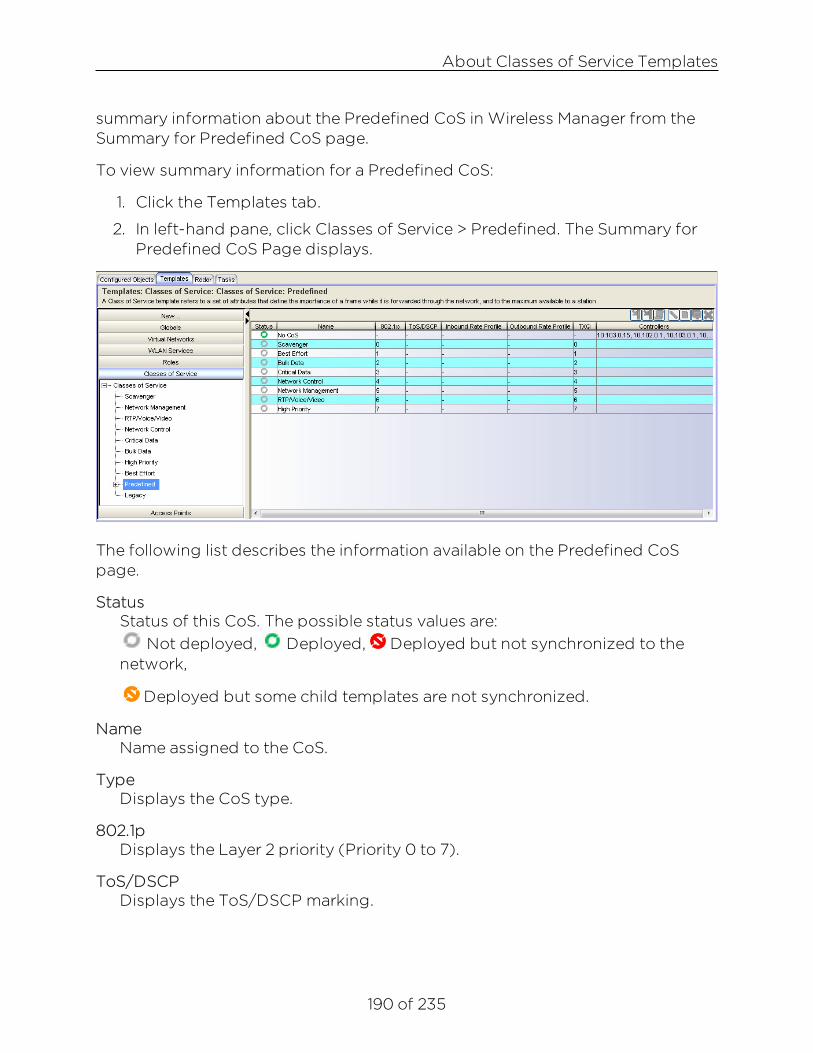
About Classes of Service Templates
190 of 235
summary information about the Predefined CoS in Wireless Manager from theSummary for Predefined CoS page.
To view summary information for a Predefined CoS:
1. Click the Templates tab.
2. In left-hand pane, click Classes of Service > Predefined. The Summary forPredefined CoS Page displays.
The following list describes the information available on the Predefined CoSpage.
StatusStatus of this CoS. The possible status values are:
Not deployed, Deployed, Deployed but not synchronized to thenetwork,
Deployed but some child templates are not synchronized.
NameName assigned to the CoS.
TypeDisplays the CoS type.
802.1pDisplays the Layer 2 priority (Priority 0 to 7).
ToS/DSCPDisplays the ToS/DSCP marking.

About Classes of Service Templates
191 of 235
Inbound Rate ProfileDisplays the inbound rate limit.
Outbound Rate ProfileDisplays the outbound rate limit.
TXQDisplays the TXQ override.
ControllersWireless Controller to which this CoS has been deployed.
Toolbar ButtonsFor a description of common toolbar buttons see Context-Sensitive Toolbar.
Viewing Detail Information About a Predefined CoSTo view information about a Predefined CoS:
1. Click the Templates tab.
2. In left-hand pane, click Classes of Service. Expand the Predefined folderand select a Predefined CoS. The Predefined CoS Details page displayswith the Template Properties tab active. For more information about thefields on this tab, see the Template Properties Tab Help topic.
3. Click on the Class of Service Properties tab to view read-only properties forthe CoS.

About Classes of Service Templates
192 of 235
Viewing Legacy CoS InformationWireless Manager no longer supports the configuration of CoS templates. Formore information, see the Legacy Template Migration Notice. You can viewsummary information about Legacy CoS templates currently defined in WirelessManager from the Summary for Legacy CoS page.
To view summary information about configured Legacy CoS:
1. Click the Templates tab.
2. In left-hand pane, click Classes of Service, and expand the Classes ofService folder and click Legacy. The Summary for Legacy CoS pagedisplays.
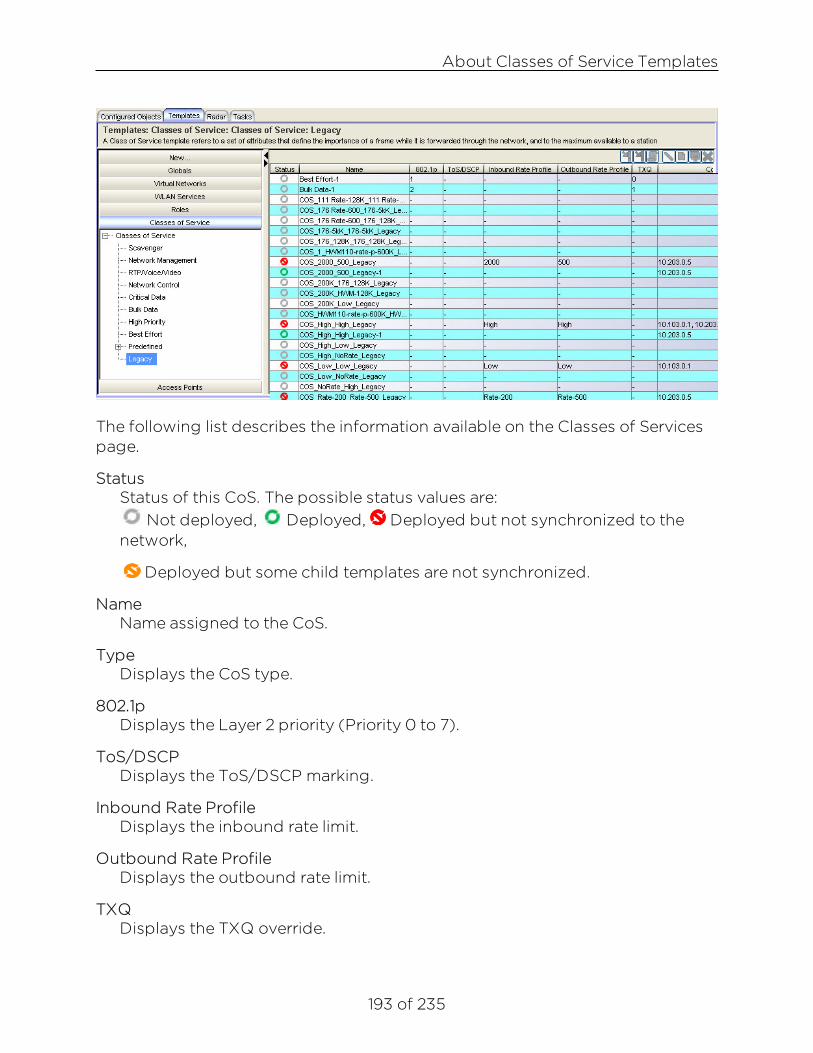
About Classes of Service Templates
193 of 235
The following list describes the information available on the Classes of Servicespage.
StatusStatus of this CoS. The possible status values are:
Not deployed, Deployed, Deployed but not synchronized to thenetwork,
Deployed but some child templates are not synchronized.
NameName assigned to the CoS.
TypeDisplays the CoS type.
802.1pDisplays the Layer 2 priority (Priority 0 to 7).
ToS/DSCPDisplays the ToS/DSCP marking.
Inbound Rate ProfileDisplays the inbound rate limit.
Outbound Rate ProfileDisplays the outbound rate limit.
TXQDisplays the TXQ override.

About Classes of Service Templates
194 of 235
ControllersWireless Controller to which this CoS has been deployed.
Viewing Detail Information About a Legacy CoSWireless Manager no longer supports the configuration of CoS templates. Formore information, see the Legacy Template Migration Notice. To view detailinformation about a Legacy CoS:
1. Click the Templates tab.
2. In left-hand pane, click Classes of Service. Expand the Classes of Servicefolder. Expand the Legacy folder and select a Legacy CoS. The Legacy CoSDetails page displays with the Template Properties tab active. For moreinformation about the fields on this tab, see the Template Properties TabHelp topic.

About Classes of Service Templates
195 of 235
Class of Service Properties Tab
Core
NameThe name by which this CoS will be known by on the Wireless Controller.
Marking
Use Legacy Priority Override defined in the WLAN ServiceSelect this checkbox to use the Priority Override defined in the WLAN as inprevious releases.
Rate Limiting
Inbound Rate LimitSelect this checkbox, and then select an inbound rate limit from the drop-down list.
Outbound Rate LimitSelect this checkbox, and then select an outbound rate limit from the drop-down list.
Transmit Queue Assignment
Transmit QueueSelect this checkbox, and then select a Transmit Queue from the drop-downlist. The Transmit Queue assignment is an override to the default TXQassignment specified in the 802.1p priority, but without remarking the actual802.1p field.

196 of 235
About Radar
Radar is a set of advanced, intelligent, Wireless-Intrusion-Detection-Service-Wireless-Intrusion-Prevention-Service (WIDS-WIPS) features that areconfigurable from Wireless Manager. Radar provides a basic solution fordiscovering unauthorized devices within the wireless coverage area. Radarperforms basic RF network analysis to identify unmanaged APs and personalad-hoc networks. The Radar feature set includes: intrusion detection,prevention, and interference detection.
The ExtremeWireless Wireless Controller supports three kinds of scan profiles:Out-of-Service, In-Service, and Guardian.
NOTE:Out-of-Service scan profiles only apply to AP26xx and AP36xx and are not supportedby Wireless Manager.
When Radar is enabled, the 37xx and 38xx APs will:
l Simultaneously provide WIDS-WIPS and wireless bridging functions.
l If configured to do so, take active countermeasures against specific typesof threat that they have detected (for more information, see PreventionTab).
NOTE:The 3705 type APs will only monitor and protect the channels for which they arebridging traffic.
This Help topic includes the following information:
l In-Service Scan Profiles
l Guardian Scan Profiles
l Cloning an Existing Radar Profile
l Radar Maintenance
l Security Threats
l Preventive Measures
In-Service Scan ProfilesIn-Service scan profiles work with APs based on the 37xx, and 38xx architectureand include the following:

In-Service Scan Profiles
197 of 235
l Whether to scan for security threats (Ad Hoc, Cracking, DoS, Internal /External Honeypot, Performance, Prohibited Device, Spoofed AP,Surveillance) and / or to classify sources of interference (Radar, Microwave,Phone, Video Bridge, Bluetooth Stereo, Bluetooth Headset, CWA).
l A set of countermeasures that lists possible prevention options to counterspecific types of threats. Includes the ability to automatically blacklistclients originating DoS / password cracking attacks. If blacklisting clients isenabled, you can set the maximum amount of time a device can beblacklisted (for more information, see Prevention Tab).
NOTE:As soon as the first In-Service scan profile is configured on a controller, the AnalysisEngine will only interact with data collectors on at most 2 controllers, its hostcontroller and its host's availability partner. Defined and enabled Out-of-Service scanprofiles will be retained. However, the Out-of-Service scan profile will only be appliedto the APs in the profile that are active on the Analysis Engine's host or on its host'savailability partner.
In Wireless Manager, APs are not part of the scan profile template definition, butare assigned during template deployment. Since only APs local to a givencontroller can be selected, if you want to assign foreign APs to your scan profileyou must manage both controllers in an availability pair. Moreover, if you want todeploy your scan profile to an AP that is already assigned to another scanprofile, it must first be removed from its current scan profile.
Viewing Summary Information About In-Service ScanProfilesTo view information about In-Service scan profiles configured in WirelessManager:
1. From the top menu, click Radar.
2. In the left pane, click Scan Profiles. The Scan Profiles summary pagedisplays.

In-Service Scan Profiles
198 of 235
The following list describes the information available on the In-Service ScanProfile Summary page.
StatusStatus of the scan profile. The possible status values are:
Deployed, Not deployed, Deployed but not synchronized to thenetwork.
NameThe name of the scan profile.
Security ScanIndicates whether the profile enables security scanning on APs assigned tothis profile.
Classify InterferenceIndicates whether the classification of sources of interference have beenenabled for this profile.
ControllersIP address of the controller(s) to which this scan profile has been deployed.
Toolbar ButtonsFor a description of common toolbar buttons see Context-Sensitive Toolbar.

In-Service Scan Profiles
199 of 235
Creating an In-Service Scan ProfileYou can create an In-Service scan profile template either manually, or by cloningan existing or deployed template.
Manually Creating an In-Service Scan Profile
To manually create an In-Service template:
1. From the top menu, click Radar
2. In the left pane, click Scan Profiles. The Scan Profiles summary pagedisplays.
3. Click the New icon . A blank Template Properties tab displays.
4. Enter a name for the new template. Enter a template description, if desired.For more information about the fields on this tab, see the TemplateProperties Tab Help topic.
The following list describes the information available in the tabs on the In-Service Scan Profiles Details page.

Guardian Scan Profiles
200 of 235
Detection tab
CoreName
Type a unique name for this scan profile.
Scan for security threatsSelect to scan for security threats (for more information, see SecurityThreats).
Rogue AP DetectionSelect this option to detect rogue APs serving open SSIDs (for example, anAP attached to an Ethernet wall jack and the AP is running an open SSID). If arogue AP is detected, countermeasures can be optionally applied to preventany station from using this rogue AP.
Listener PortEnter the UDP port for rogue AP detection.
Classify Source of InterferenceInterference classification compares patterns in RF interference to knowninterference patterns to help identify the source of the interference. All APsbased on the 37xx, and 38xx architecture are capable of performinginterference classification
Prevention TabCountermeasures
Select the appropriate prevention measures for the selected profile. For adescription of each option, see Preventive Measures.
Assigned APs Tab
Shows the list of APs by controller to which this scan profile template as beendeployed.
Guardian Scan ProfilesGuardian scan profiles are only supported by the AP3710(i/e), AP3715(i/e),AP3765(i/e), AP3767e, AP3805(i/e), AP3825(i/e), and AP3865e. APs assignedto a Guardian scan profile operate in a dedicated Radar mode.

Guardian Scan Profiles
201 of 235
l An AP operating in Guardian mode does not bridge traffic and insteaddevotes all of the AP’s resources to threat detection and countermeasures.
l An AP is added to a Guardian scan mode in its entirety. There is no optionto dedicate one radio to scanning and the other to forwarding.
l An AP assigned to a Guardian scan profile stops providing any services(WLAN service, load groups, site) immediately.
Guardians don’t count towards the number of APs licensed by NetSight. APsservicing a WDS / mesh WLAN cannot be added to a Guardian scan profile.
When an AP is added to a Guardian scan profile it retains its AP, radio andWLAN service settings, which you can continue to configure (using AP Profiletemplates) like those of any other AP. Some settings, such as changes toantenna and country, are even forwarded to Guardians.
Unlike APs assigned to in-service scan profiles which only monitor and protectthe channels for which they are bridging traffic, APs assigned to guardian scanprofiles will monitor and protect those channels specified in the template. Aguardian however will not perform active countermeasures or scan regulatoryprohibited channels, nor will it defend against threats on DFS channels but willperform passive scanning of DFS channels in order to detect and report suchthreats.
Viewing Summary Information About Guardian ScanProfilesTo view information about Guardian scan profiles configured in WirelessManager:
1. From the top menu, click Radar.
2. In the left pane, click Scan Profiles > Guardian Scan. The Guardian ScanProfiles summary page displays.

Guardian Scan Profiles
202 of 235
The following list describes the information available on the Guardian ScanProfile Summary page.
StatusStatus of the scan profile. The possible status values are:
Deployed, Not deployed, Deployed but not synchronized to thenetwork.
NameThe name of the scan profile.
Security ScanIndicates whether the profile enables security scanning on APs assigned tothis profile.
Classify InterferenceIndicates whether the classification of sources of interference have beenenabled for this profile.
ControllersIP address of the controller(s) to which this scan profile has been deployed.
Toolbar ButtonsFor a description of common toolbar buttons see Context-Sensitive Toolbar.
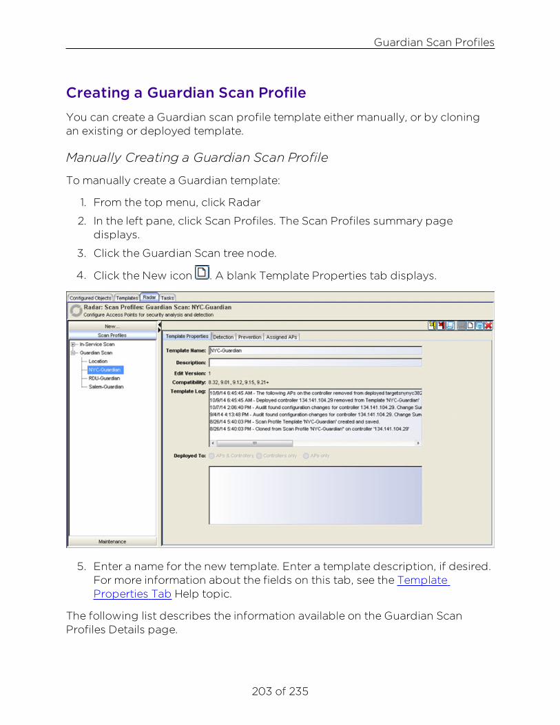
Guardian Scan Profiles
203 of 235
Creating a Guardian Scan ProfileYou can create a Guardian scan profile template either manually, or by cloningan existing or deployed template.
Manually Creating a Guardian Scan Profile
To manually create a Guardian template:
1. From the top menu, click Radar
2. In the left pane, click Scan Profiles. The Scan Profiles summary pagedisplays.
3. Click the Guardian Scan tree node.
4. Click the New icon . A blank Template Properties tab displays.
5. Enter a name for the new template. Enter a template description, if desired.For more information about the fields on this tab, see the TemplateProperties Tab Help topic.
The following list describes the information available on the Guardian ScanProfiles Details page.
Guardian Scan Profiles
204 of 235
Detection Tab
CoreName
Type a unique name for this scan profile.
Scan for security threatsSelect to scan for security threats (for more information, see SecurityThreats).
Classify Source of InterferenceInterference classification compares patterns in RF interference to knowninterference patterns to help identify the source of the interference. All APsbased on the 37xx architecture are capable of performing interferenceclassification.
Channels to Monitor2.4 GHz
Click the 2.4 GHz tab and select additional channels to be monitored withinthis band for the scan profile.
5.0 GHzClick the 5 GHz tab and select additional channels to be monitored within thisband for the scan profile.Note: The AP371x and AP38xx automatically scan 40 MHz and 20 MHz widechannels.
Prevention TabCountermeasures
Select the appropriate prevention measures for the selected profile. For adescription of each option, see Preventive Measures.
Defense OptionsSelect the maximum number of channels to defend concurrently. This optionapplies separately to each radio of a Guardian AP so that overall it can defendconcurrently a maximum of 8 channels but only 4 on each radio.
Assigned APs Tab
Shows the list of APs by controller to which this scan profile template as beendeployed.

Cloning an Existing Radar Profile
205 of 235
Toolbar ButtonsFor a description of common toolbar buttons see Context-Sensitive Toolbar.
Cloning an Existing Radar ProfileTo launch the Clone Scan Profile wizard:
1. Click the Radar tab.
2. In left-hand pane, click the New bar, expand Clone and select:
l Clone an In-Service Scan Profile, the Clone Scan Profile Wizardlaunches
l Clone a Guardian Scan, the Clone Scan Profile Wizard launches
l Clone Radar Maintenance, the Clone Radar Maintenance Wizardlaunches
3. In the New template name field, enter a name for the new template.
4. Select one of the following:
l Base template on a deployed Scan Profile Template – This options letsyou create a template by copying the settings of a deployed templateon a Wireless Controller.
l Base template on an existing Scan Profile Template – This option letsyou create a template by copying a template that is alreadyconfigured.
5. The window that lists the selected item becomes active. Click the ViewSelected button to view detailed information about the cloning source.Click Next to view the Cloning Summary page.
6. The Cloning Summary page displays the configuration that you selected.Click Finish to clone the configuration or Cancel to discard it.
Radar MaintenanceThe Radar Maintenance template is used to maintain the Radar lists of APs. Youcan view summary information about Radar Maintenance templates currentlydefined in Wireless Manager from the Radar Maintenance Summary page. Fromthis page, you can also perform the following tasks:

Radar Maintenance
206 of 235
l Deploy the template.
l Edit, clone, or delete an existing Radar Maintenance template.
l Export a Radar Template configuration to the CLI.
l Create new Radar Maintenance templates.
To view summary information about configured Radar Maintenance templates:
1. Click the Radar tab.
2. In left-hand pane, click Maintenance. The Radar Maintenance Summarypage displays.
The following list describes the information available on the Radar MaintenanceSummary page.
StatusStatus of this Radar Maintenance template. Options include:
Deployed, Not Deployed, Deployed but not synchronized to thenetwork,

Radar Maintenance
207 of 235
Deployed but some templates not synchronized.
NameName assigned to the Radar Maintenance template.
Security ScanIndicates whether the profile enables security scanning on APs assigned tothis profile.
Classify InterferenceIndicates whether the classification of sources of interference have beenenabled for this profile.
ControllersIP address of the controller(s) to which this scan profile has been deployed.
Toolbar ButtonsFor a description of common toolbar buttons see Context-Sensitive Toolbar.
Radar provides a list of APs organized by categories based on the scan resultsof the Analysis Engine. Radar will try to assign each discovered AP to one ofthese categories. If it can't find a specific category for the AP, it will assign it tothe Uncategorized APs category. Uncategorized APs require manualclassification. To get the best protection from Radar, classify uncategorized APsas soon as possible. You can manually assign APs from one category to almostany other using Radar.
Radar Maintenance templates can be deployed to 8.21+ Wireless Controllers(EWC) with Security Analysis Engine enabled. When creating a RadarMaintenance template, it is recommended to select all Wireless Controllers fromthe same mobility zone. When a new template is created, the "Load ScanResults" button retrieves all Authorized, Friendly, Prohibited, and UncategorizedAPs from the selected controllers. For an existing template, its label changes to"Load Uncategorized APs" and it only retrieves Uncategorized APs fromselected controllers. If an AP is found in multiple categories, any conflicts areresolved according to the following priority: Prohibited > Authorized > Friendly> Uncategorized
AP CategoriesAPs are labeled as belonging to one of the following categories when they areadded to the Analysis Engine database:

Radar Maintenance
208 of 235
l Uncategorized APs - Scanned APs that do not fall into any other category.
l Friendly APs - These are APs that are not part of the authorized network,but they operate in the vicinity of the authorized network. Friendly APs areoperated by a neighboring enterprise for their own use. Authorized APsbased on the AP37xx, and AP38xx architecture can prevent authorizeddevices from using friendly APs.
l Authorized APs - APs that can be used by devices authorized to use thenetwork. APs can be added to the list automatically (for example, if the APsare active on the current host or the host’s availability partner) or manually.This is useful if you have a standalone AP or third-party AP that itsauthorized devices should be allowed to use even though the AP is notmanaged by a controller. WM has the added convenience of being able toadd all those APs from any managed controller. Note: The set ofAuthorized APs deployed to each EWC will only include those APs whichare considered Pre-Authorized on that EWC. Any "hidden" AuthorizedAPs (i.e., those local & foreign APs associated with the EWC) will beexcluded, for the purpose of deployment and auditing.
Pre-Authorized = Authorized APs of template – local APs of the targetEWC and peer.
l Prohibited APs - APs manually added to the Radar database so that theRadar WIDS-WIPS system will detect them and, if so configured, protectagainst them. An example of manually prohibited APs might be those thatwere stolen from the authorized network and now could be used togenerate a security breach.
When a prohibited AP is detected, the following actions can be taken:
l Report presence only - When the MAC address of the prohibited APis detected by an authorized scanning AP, the prohibited APspresence will be reported in an event message. This will result in thepresence of the MAC being included in the Radar threat reports.Radar will not take any countermeasures against the device with theMAC address.
l Treat like an internal honeypot AP - The device with the MAC addressis considered to be as harmful as an AP that is 'impersonating' one ofthe authorized APs. If countermeasures are enabled, no devices willbe allowed to associate to this MAC address, including devices ofother neighboring enterprises.
Radar Maintenance
209 of 235
l Treat like an external honeypot - The device with the entered MACaddress is considered to be as harmful as an AP that is advertising apopular SSID. Authorized devices will be prohibited from roaming tothe device with this MAC address. Unauthorized devices andunrecognized devices will be allowed to roam to the device with theMAC address.
Differences between the Radar Maintenance Templateand Other Templates:
l Import Behavior: Unlike other templates, when importing RadarMaintenance settings, a template is not matched based on is content, butinstead by its selected controllers. If a template exists for the EWC, theimported Uncategorized, Friendly, Authorized, and Prohibited APs will bemerged with those of the existing template. Any conflicts are resolved byleaving the AP in its current category. If no template exists for the EWC anew template is created.
l Audit: Authorized, Friendly, and Prohibited APs are audited.Uncategorized APs are not audited.
l Undeploy: If a controller is unselected during deployment, the RadarMaintenance settings on that EWC are not changed.
Manually Creating Radar Maintenance TemplateTo manually create a Radar Maintenance template:
1. From the top menu, click Radar
2. In the left pane, click New > Add Radar Maintenance. A blank TemplateProperties tab displays.

Radar Maintenance
210 of 235
3. Enter a name for the new template. Enter a template description, if desired.For more information about the fields on this tab, see the TemplateProperties Tab Help topic.
The following list describes the information available on the Radar MaintenanceProfiles Details page.
Maintenance TabSelected Controllers
List of 8.21+ managed Wireless Controllers with Security Analysis Engineenabled.
Access PointsDisplays the lists of APs by category. Categories include: Uncategorized,Friendly, Authorized, and Prohibited.
Assign APsSelect a new category for the selected AP (from the category tabs underAccess Points) and click Apply.
Security Threats
211 of 235
Security ThreatsThreat APs are APs that have been detected performing one or more types ofattack on the authorized network.
Each AP defined on the controller has a text location attribute that can be setusing Wireless Manager, the controller's GUI, or CLI. By default the locationattribute is empty for all APs, which implicitly corresponds to a location of"World". It is strongly recommended that you set the location attribute of eachAP. The attribute should be set so that APs at the same location have exactly thesame location attribute. For example, all the APs on the 3rd floor of a buildingcould have the same location, such as "Boston/123 4th Street/3rd floor".
The types of threat recognized by the Radar WIDS-WIPS system include:
l Ad Hoc Device - A device in ad hoc mode can participate in direct device-to-device wireless networks. Devices in ad hoc mode are a security threatbecause they are prone to leaking information stored on file system shares.
l Cracking - This refers to attempts to actively crack a password or networkpassphrase (such as a WPA-PSK). The Chop-Chop attack on WPA-PSKand WEP is an example of an active password cracking attack.
l Denial of Service (DoS) attacks - DoS attacks
l External Honeypot - An AP that is attempting to make itself a man-in-the-middle by advertising a popular SSID, such as an SSID advertised by acoffee shop or an airport.
l Interference Source - A device generating a radio signal that is interferingwith the operation of the wireless network. An example of an interferencesource is a microwave oven, which can interfere with 2.4GHz transmissions.
l Internal Honeypot - An AP that is attempting to make itself a man-in-the-middle by advertising an SSID belonging to the authorized network.
l Performance - Performance issues pertain to overload conditions thatcause a service impact. Performance issues aren't necessarily securitythreats, but many types of attack do generate performance issues.
l Prohibited Device - A MAC address or BSSID is detected that matches anaddress entered manually into the Radar database.
l Rogue AP - An unauthorized AP connected to the authorized wired orwireless network. Any type of threat can be further classified as a 'Rogue'.

Security Threats
212 of 235
In addition, uncategorized and friendly APs that are found to be connectedto the authorized network can be classified as rogue threats.
l Spoofed AP - An AP that is not part of the authorized network isadvertising a BSSID (MAC address) that belongs to an authorized AP onthe authorized network.
l Surveillance - A device or application that is probing for information aboutthe presence and services offered by a network.
Rogue/Threat/Interference - Active & Inactive/AgedEventsWireless Manager receives threat and interference events from 8.21+ WirelessControllers and forwards them to Console which triggers alarms on APs, clients,and controllers to be automatically created and cleared. As for the "Rogue AP"events reported by 8.01 & 8.11 Wireless Controllers, Wireless Manager convertsthem to threats and handles them in the same way as threats reported by 8.21+Wireless Controllers.
NOTE:After the release of 9.01 Wireless Controllers, the term 'Rogue' is used to identifythose threats that have been determined to be connected to the authorized network.
Threats and interference events are uniquely identified by the followingattributes:
l Threat Name - All threats have a well defined name. Interference eventshave the following names: Radar, Microwave, Phone, Video Bridge,Bluetooth Stereo, Bluetooth Headset, and CWA.
l Subject MAC - The MAC to which this threat applies. For spoofed AP,internal / external honeypot it is the advertised BSSID of the threat AP. Forthreats tracked at "MAC" scope, it is the address against which the threat istracked. For all other threats this field is the broadcast MAC address(FF:FF:FF:FF:FF:FF).
l Location - A hierarchical string like "World/Canada/Ontario/Thornhill/…".Default is "World".
l Channel - The detected frequency in MHz.
Whether an AP detects a threat or source of interference on the channel that it isproviding service on or as a result of scanning across multiple channels, it willsend an "Active" event to the Wireless Controller when it is first detected and an"Inactive" event when it is no longer detected. Such events are forwarded to

Security Threats
213 of 235
Wireless Manager, which sends them to Console to be correlated into alarmsagainst APs, clients, and controllers.
An "Active" alarm is automatically cleared when an "Inactive" event is receivedfrom the Wireless Controller for the same attributes as the "Active" threat (forexample, threat name + subject MAC + location + channel). If for some reasonthe AP fails to report to the controller that a threat is no longer active, after onehour of inactivity, the Wireless Controller will automatically report the threat toWireless Manager as "Aged".
When a threat is also determined to be a 'rogue', in addition to creating the"Threat Active" alarm (with Warning severity), Wireless Manager will also createa "Rogue Active" alarm (with Critical severity).
If the controller reports that the threat is still active but no longer considered tobe a rogue, Wireless Manager will clear the “Rogue Active” alarm.
If the controller reports that the threat is no longer active, Wireless Manager willcreate a “Threat Inactive” alarm, which will clear any “Threat Active” or “RogueActive” alarms with the same key (threat name + subject MAC + location +channel).
To view the list of active threats (including sources of interference), click theAlarms tab located at the bottom of the NetSight screen. For more informationon the Alarms Tab, see theNetSight Console User Guide.
Alarms Tab
Threat and interference events from Wireless Manager are correlated into alarmsin Console according to the "Rogue Active", "Rogue Inactive", "Threat Active","Threat Inactive", "Interference Started", and "Interference Stopped" alarmdefinitions in the Alarms Manager.
To configure the various threat related alarms, click the Alarms Manager iconlocated on the NetSight Toolbar. For more information on the Alarms ManagerWindow, see theNetSight Console User Guide.

Security Threats
214 of 235
Alarms ManagerWindow
Rogue Detection and PreventionBoth Guardian and In-Service Scan Profiles can be configured to perform roguedetection and prevention. Although In-Service scan profiles support roguedetection for 9.01 or later controllers, Guardian scan profiles only support roguedetection for 9.12 or later controllers.
The ability of the controller to detect rogues, is currently limited to rogue APsserving open SSIDs. This is intended to catch the more common scenario of anemployee innocently attaching an AP (running an open SSID) to his Ethernetjack.
Rogue DetectionRogue Detection is licensed as part of any Wireless Controller Radar capacitylicense. The following categories of BSSIDs are excluded from the roguedetection mechanism:
l Authorized and Pre-Authorized BSSIDs
l Encrypted BSSIDs

Security Threats
215 of 235
l Spoofed APs
The Wireless Controller considers the following categories of BSSIDs aspotentially rogue; they are tested in descending priority order:
l Threat
l Uncategorized
l Friendly
Rogue Testing
Rogues are re-tested after four hours (in the following order): Rogue, and thenRogue Candidates (Threat, Uncategorized, Friendly). The testing AP associatesto the candidate rogue like a normal wireless client, and upon success:
l Initiates DHCP exchange to obtain an IP address.
l ARPs for the gateway MAC.
l Sends Layer 3 test messages to the wired interface of the testing AP. If thetesting AP receives any of the messages then the candidate rogue isconsidered connected to the authorized or corporate network and itsstatus is updated to rogue.
The testing AP reports the following information for a rogue:
l The client wireless MAC address that was inserted as the source in the L2header.
l The source MAC address received at the wired interface. If it matches theclient wireless MAC address, the rogue is on the same segment and isbridging rather than routing or NATing. If it is different, then there is arouter or NAT between the AP's wireless and wired interfaces on thenetwork. The rogue could be routing or NATing.
l The IP address issued to the client wireless interface by DHCP.
l The IP address in the source address field of the L3 header. If this differsfrom the IP address assigned to the AP’s wireless client interface, thenthere is a NAT between the AP’s wireless client interface and the AP’swired interface. If it is the same then there is no NAT between the AP’swireless client and wired interfaces.
l The difference between the TTL in the frame when it was sent fromthe wireless client and the TTL in the frame received at the AP’s wiredinterface.

Preventive Measures
216 of 235
Rogue PreventionOnce detected, a rogue AP must be isolated to prevent it from being used. APsperforming countermeasures against rogue APs:
l Send de-authentication frames to its clients on behalf of the rogue AP; theyare treated like spoofing APs with users being prohibited from using therogue AP via a combination of broadcast de-authentications and targetedde-authentications.
l May have other tasks to perform limiting their ability to prevent stationsfrom associating to the rogue for short periods of time.
Preventive MeasuresThis section describes the countermeasures that can be configured for In-Service and Guardian scan profiles using the Prevention tab.
l Prevent authorized stations from roaming to external honeypot APs - AnAP that is attempting to make itself a man-in-the-middle by advertising apopular SSID, such as an SSID advertised by a coffee shop or an airport.
l Prevent authorized stations from roaming to friendly APs -APs that are notpart of the authorized network, but operate in the vicinity of the authorizednetwork.
l Prevent any station from using an internal honeypot AP - An AP that isattempting to make itself a man-in-the-middle by advertising an SSIDbelonging to the authorized network.
l Prevent any station from using a rogue AP - An unauthorized APconnected to the authorized wired or wireless network.
l Prevent any station from using a spoofed AP - An AP that is not part of theauthorized network but is advertising a BSSID (MAC address) that belongsto an authorized AP on the authorized network.
l Drop frames in a controlled fashion during a flood attack (for example, ratelimiting the flooded frames) - For preventing some types of Denial ofService (DoS) attacks from affecting the authorized network instead of justthe target AP.
l Prevent any station from using an ad-hoc mode device - Deauthenticationmessages are used to prevent devices from using an ad hoc mode device.

Preventive Measures
217 of 235
l Remove network access from clients originating DoS attacks and passwordcracking attacks - Used to prevent the propagation of the DoS attack fromthe AP to the authorized network. Many types of DoS attacks involvedeluging an AP with a large volume of messages of one or two specifictypes. When this option is enabled, the AP will apply rate limits to thespecific type of frame that is being deluged.
l Remove network access from violating clients for a period of time - Used toprevent clients from successfully associating to any authorized APs. This isparticularly useful for preventing devices performing active passwordcracking attacks from successfully brute forcing a password.

218 of 235
Managing Tasks
A task deploys or transfers a template configuration from the Wireless Managerto one or more target Wireless Controllers.
This section includes the following topics:
l About Tasks
l Creating, Scheduling, and Deploying Tasks
l Deploying a Template
l Deploying Point of Presence
l Deploying WLAN Service Assignments in Bulk
l Monitoring Tasks

219 of 235
About Tasks
When you create a new or modify an existing template configuration, it is storedin Wireless Manager and does not take effect until you activate the changes.Depending on the type of template, you activate the configuration changes bycreating a task that deploys the template to one or more Wireless Controllers,APs, AP Groups, or AP Load Groups.
When a task executes, Wireless Manager logs into the target WirelessController’s CLI and deploys the template so that the Wireless Controller’sconfiguration matches the template configuration. The task records the outcomeof the execution, saves it as part of the task and logs the event.
Tasks provide progress reports when they execute. Wireless Manager displaysinformation about the percentage of task completion as well as informationabout the user who initiated the task. If two tasks execute at the same time andthey have conflicting requirements (for example, if each task configures thesame Wireless Controller) the tasks will run serially. Wireless Manager generatesan event to show which one of the tasks was delayed and why.
Upon task execution, Wireless Manager performs the following:
l Applies the template configuration to each target Wireless Controlleridentified by the task and updates the Wireless Controller configurationwith the data specified for it in the task.
l Updates the task details page to contain a summary description of theexecution process as well as the complete set of CLI scripts that executedas part of the task.
l Sets the task status to success, partial success or failure based on theoutcome of task execution.
l Updates the templates on which the task was based to include a historyrecord showing that an attempt to deploy them was made at a particulardate and time and to show whether the Wireless Controller configuration issynchronized to the template.
l Updates the list of currently deployed targets.
l Generates a log to record the task executed and its success.
l Augments the task description with a history showing which objects thetask was applied and whether the task succeeded on that object or not.
l Generates events for any significant task failure.

220 of 235
Creating, Scheduling, and Deploying Tasks
The Wireless Manager provides wizards that take you through the steps ofcreating, scheduling, and deploying a task. During task creation you can:
l Select appropriate targets.
l Select the time at which the task will run.
l Collect customization data for each Wireless Controller.
After you have created a task, you can later suspend and reschedule the tasks aslong as they have not begun to deploy.
Available task deployment wizards include:
Configured Objects Tasks
l Deploy RADIUS
l Deploy Topology
VNS Tasks
l Deploy VNS
l Deploy WLAN Service
l Deploy WLAN Assignments
l Deploy Point of Presence
Global Tasks
l Deploy Globals Template
AP Tasks
l Deploy AP Profile
Radar Tasks
l Deploy In-Service Scan Profile
l Deploy Guardian Scan Profile
l Deploy Radar Maintenance Template

221 of 235
Deploying a Template
Creating a TaskYou can create a task using a specific wizard.
To launch the wizard:
1. Click the Tasks tab.
2. In left-hand pane, click New > Specific Tasks > Deploy Wizard. The wizardlaunches.
Deploying a Task
Select Item to Deploy Page
Select the name of a specific configuration from the list and enter a name for thetask. If you do not assign a name, Wireless Manager appends TaskN to the endof the name of the selected configuration, whereN is an incremental integerstarting with 1.
Enter Task Name
In the Name field, enter a unique name for this task.
Select Targets and Deployment Time Page1. In the Available Targets window, select the name of one or more Wireless
Controllers, APs, AP groups, or AP Load Groups to apply theconfiguration. Deployment items to consider:
l If you deploy a template to only one member of an availability pair, nosynchronization will occur. If this is not what you intended, you mustselect both Wireless Controllers in the pair.
l If a template is currently deployed to an availability pair and you onlywant to deploy to one of the Wireless Controllers in the pair, you mustfirst undeploy on both.

Deploying a Template
222 of 235
l If an AP Group has no APs, or in the case of an AP Profile deploymentit contains no APs of an appropriate hardware type, it is displayed asgreyed out.
l Selecting any AP, AP Group, or AP Load Group automatically selectsthe parent Wireless Controller. This Wireless Controller cannot bedeselected until all APs causing it to be selected have beendeselected. When you try to deselect a Wireless Controller, if there areany targets making it a mandatory target, you will be informed ofwhich ones they are, so that you can deselect them.
l Selecting an AP Group will result in all of its member APs and theirWireless Controllers being selected. If an AP is selected because anAP Group containing it is selected, it cannot be deselected until theAP Group is deselected.
2. To schedule the task deployment, select one of the following options:
l Execute Immediately – Places the task in the queue to executeimmediately, or as soon as possible if other tasks are already in thequeue.
l Do Not Execute – Stores the task for future execution.
l Specify Time – Enables you to schedule task execution. You can selectthe date and time when you want the task to execute.
l Enforce using Policy Manager – Enables you to enforce the templatethat references a PM-Policy or PM-CoS for the selected deploymenttargets.
3. Enter a Port or Mask for the Controller, if applicable. If the topology is partof a topology group, this displays all topologies in the group.
4. When deploying a template, if a suitable AP Group is not listed, click AddAP Group to create one.
a. The Create New AP Group window displays
b. In the Name field, enter the name of the new AP group.
c. To include an AP into the named AP group, select an AP from theAvailable APs window and use the arrow key to move it into the APsin Group window. Use the Shift key to add multiple APs that are listedadjacent to each other; use the Ctrl key to add several APs that are notlisted adjacent to each other. To remove an AP from the named APgroup, select an AP in the APs in Group window and use the arrowkey to move it into the Available APs window.

Deploying a Template
223 of 235
d. Click OK to save the AP group or click Cancel to discard the AP groupconfiguration.
Selecting Targets for VNS/WLAN Service Deployment
l The Change Radio Assignments check box only applies to APs, and APGroups, and is only enabled when either of these is selected. As for radioassignments for AP Load Groups, these are specified as part of the APLoad Group definition.
l The Default WLAN Service Assignment check box is only enabled if'Change Radio Assignments' is selected.
l An AP Load Group can only be selected as a valid target for deployment ifit is synchronized. Moreover, you will not be allowed to re-deploy atemplate that was previously deployed to an AP Load Group and hasbecome un-synchronized, until you first re-deploy the AP Load Group ordelete it.
l Selecting an AP Group will result in all of its member APs and their WirelessControllers being selected. Similarly, any radio assignments made to an APGroup will apply to all of its member APs. If you want to customize theradio assignments of any APs belonging to an AP Group that has radioassignments, you must first remove them from the AP Group.
l If the VNS/WLAN being deployed is a remotable VNS/WLAN then anyWireless Controllers implicitly represented by an AP, AP Group, or AP LoadGroup which are part of a Mobility Zone will be automatically selected.
For more information, see About WLAN Service Templates and About VirtualNetwork Services (VNS) Templates.
Selecting Targets for Remotable VNS/WLAN Service Deployment
This page lists available target Wireless Controllers that can host the remotableWLAN in a Mobility Zone. Any stand-alone Wireless Controllers are listed forreference only and the selection is not editable. Select at least one WirelessController in each Mobility Zone where the template will be deployed asremotable.
Remotable WLAN templates are identified by selecting Remotable on theAdvanced dialog within the WLAN Services Template page. For moreinformation, see Manually Creating a WLAN Service Template.

Deploying a Template
224 of 235
NOTE:When deploying a VNS, it is only deployed on those Wireless Controllers markedremotable. The remotable Wireless Controller also receives the remotable WLANservice for which the user may be prompted to specify per-Wireless Controllersettings for Default Topology (see EWC Specific Topology Settings Page), RADIUS (seeEWC Specific RADIUS Servers Settings Page) or captive portal (see EWC SpecificCaptive Portal Settings Page) during deployment. The other Wireless Controllersreceive the remote WLAN service definition which does not include any per-controllerAuth & Acct settings (see WLAN Service Template Configuration Page).
Remove a remotable template by clearing the target selection.
NOTE:Clearing the remotable Wireless Controller will not only remove the remotableWireless Controller, but also remove all remote Wireless Controllers in the sameMobility Zone.
Verify TargetsThis page provides a list of deployed targets (EWCs, APs, AP Groups, and APLoad Groups) for the selected template. Targets can be removed or additionaltargets can be added by clicking the Prev button and editing the selection asnecessary.
Specifying EWC Specific Settings
EWC Specific Topology Settings Page
This page displays information about the target Wireless Controllers andenables you to customize their configurations. For more information, seeCreating a Network Topology Configuration.
1. Select the name of the Wireless Controller that you want to customize.
2. Depending on the mode of the topology, the following per-controllersettings can be configured:
l Bridged at EWC - port, interface IP, mask
a. From the drop-down menu, select the physical multicast port toassign to the Wireless Controller.
If the multicast port for a controller is changed, and the template isdeployed successfully, the per-controller settings in all othertemplates referencing this property are updated accordingly.
l Routed - multicast, gateway, mask, DHCP

Deploying a Template
225 of 235
a. If available, click the Configure DHCP Settings button toconfigure DHCP. The DHCP Settings window displays.
b. Select from the following DHCP settings:
l None
l Use Relay
l Local Server
c. Click Close to close the DHCP Setting window.
EWC Specific RADIUS Servers Settings Page
This page displays information about the target RADIUS servers and enablesyou to customize their configurations.
1. Select the name of the Wireless Controller that you want to customize.
2. Under Controller, select a Wireless Controller priority.
3. From the drop-down menus, select the desired authentication andaccounting configuration. For more information, see Creating a RADIUSServer Definition.
EWC Specific Captive Portal Settings Page
This page displays information about Captive Portal servers and enables you tocustomize their configurations.
1. Select the name of the Wireless Controller that you want to customize.
2. Settings include:
a) Firewall Friendly External: Redirection URL, FQDN for EWC IP, DefaultRedirection URL.
b) Internal, Guest Portal, Guest Splash: Default Redirection URL, FQDN forGateway IP.
c) External: Redirection URL, IP Address, Port.
3. Click Next.
Controller Specific Radar Settings
This page displays information about Radar settings for both single controllersand availability pairs.
Deploying a Template
226 of 235
1. Under Single Controller, select whether or not to enable the SecurityAnalysis Engine. For more information, see About Radar.
2. Under Availability Pairs:
l For controllers in availability running V9.15 or later software, selectwhether or not you wish to enable the Security Analysis Engine ineach availability pair.
l For controllers in availability running software prior to V9.15, only onecontroller should have the Security Analysis Engine enabled in eachavailability pair.
3. Click Next.
Verify AP MembershipThis page displays APs that are members of a Guardian scan profile. When anAP is assigned to a Guardian scan profile it will stop providing forwardingservices, or operating as a load group or site member. Any APs that show up inthe "APs to be added" section of the "Verify AP Membership" dialog, onceassigned to the guardian scan profile, will stop providing other services (WLANServices, Load Groups, and Sites). Any APs that show up in the "APs to beremoved" section of this dialog, upon deployment will have their correspondingservices re-instated.
1. Click the Tasks tab.
2. In left-hand pane, click New > Radar Tasks > Deploy Guardian Scan Profile.The wizard launches.
3. On the Verify AP Membership dialog, expand the tree for the desiredcontroller.
4. Click Next.
Execute Task PageA message displays stating whether the task was successfully deployed. Clickclose to close the window or click View Log to view detailed log informationabout the task.

227 of 235
Deploying Point of Presence
The Point of Presence wizard provides the ability to change the point ofpresence of a Policy Manager enforced role on a controller. When a new PM roleis enforced on a controller, AP Filtering is enabled by default.
Using this wizard you can change this setting subject to the followingrestrictions.
l If a role references a B@AP topology (in policy rules, default access control,or egress VLANs) the controller automatically enables AP Filtering.
l If a role's option "Allow action in policy rules, contains to the VLANassigned by the role." is selected then WM will allow the user to configure"Custom AP Filtering".

228 of 235
Deploying WLAN Service Assignments in Bulk
The bulk WLAN service assignment wizard allows you to assign one or more(already deployed) WLAN Service templates to the radios of APs, AP Groups, orAP Load Groups.
1. Enter Task Name. In the Name field, enter a unique name for this task.
2. Select WLAN Services. Select the WLAN service templates on which tomodify radio assignments. You must select at least one WLAN servicetemplate. For more information, see Creating a WLAN Service Template.
3. Select Targets. Select one or more Wireless Controllers, APs, AP groups, orAP Load Groups to apply the configuration.
4. Modify Radio Assignments. This page shows the current WLAN-Radioassignments for each AP, AP Group, and AP Load Group.
l For AP Load Groups, click the desired square to change theassignment of the WLAN on the AP Load Group.
l For APs and AP Groups, you can modify the assignments by selectingthe radios and then clicking the desired WLAN-AP intersections in thetable.
5. Execute Task. A message displays stating whether the task wassuccessfully deployed. Click Close to close the window or click View Log toview detailed log information about the task.

229 of 235
Monitoring Tasks
After you create tasks, Wireless Manager stores task definitions for historicalpurposes and so that you can view the list of tasks and their current status, copy,or edit the tasks.
Because tasks are associated with a large volume of data, only a limited numberof them can be retained. You can configure the number of executed tasks to beretained for historical purposes in Wireless Manager’s options. Wireless Managerenforces this restriction by a nightly cleanup process.
You can view detailed historical information about all tasks created, includingthe actual CLI scripts executed by the task and the data actually deployed by thetask as part of the task definition.
For general information about tasks, go to Managing Tasks.
This Help topic includes the following information:
l Viewing Task Status and Historical Summary Information
l Viewing Task Details
l Editing a Task
l Deleting a Task
l Rescheduling a Task
Viewing Task Status and Historical Summary InformationYou can view status and historical summary information about all tasks createdfrom the Task Summary page.
To view the Task Summary page:
1. Click the Tasks tab.
2. In left-hand pane, click Task management > Task History. The TaskSummary page displays.

Monitoring Tasks
230 of 235
The following list describes the information available on the Task Summarypage.
Status
l Status of the task. Options include:
l Not scheduled — Task is created but has not yet executed or beenscheduled to execute.
l Pending — The task is scheduled but has not yet executed.
l Pending Failure – The task is scheduled but has not yet executed, howeverdue to incompatible targets it is expected to fail.
l Partial success — The task finished executing but did not completelysucceed. It may not have been deployed to one of the targets or onlypartially deployed on a target.
l Running — Task is currently executing.
l Success — The task finished executing successfully on all targets.
l Failed — Task execution failed completely.
l Deleting — Task is currently being deleted.
IDA numeric string that identifies the order in which the task was created. Forexample, ID 1 identifies this as the first task created. ID 10 identifies it as thetenth task created.

Monitoring Tasks
231 of 235
NameName associated with the task. When a task is created, you can assign aname to the task or Wireless Manager will assign a name for you byappending TaskN to the name of the object the task will deploy.
Task TypeThe type of task. Options are Policy, VNS, AP Profile, WLAN service, WLANassignment, RADIUS, Topology, Rate Profile, Classes of Service, and LoadGroup.
CreatedDate the task was created.
ScheduledIdentifies:
l whether the task has already executed
l whether the task is scheduled to execute
l the time and date of task that is scheduled to execute.
CreatorName of the user who created the task.
Toolbar ButtonsFor a description of common toolbar buttons see Context-Sensitive Toolbar.
Viewing Task DetailsYou can view detailed information about a specific task from the Task Detailspage for that task.
To view the Task Details page:
1. Click the Tasks tab.
2. In left-hand pane, click Task management > Task Details. The Task Detailspage displays.
3. In the left-hand pane, click on a Task Name from the list. The Task Detailspage for that task displays.

Monitoring Tasks
232 of 235
The following list describes the information available on the Task Details page.
Task Details TabStatus
Status of the task. Options include:
l Not scheduled — Task is created but has not yet executed or beenscheduled to execute.
l Pending — The task is scheduled but has not yet executed.
l Pending Failure – The task is scheduled but has not yet executed, howeverdue to incompatible targets it is expected to fail.
l Partial success — The task finished executing but did not completelysucceed. It may not have been deployed to one of the targets or onlypartially deployed on a target.
l Running — Task is currently executing.
l Success — The task finished executing successfully on all targets.
l Failed — Task execution failed completely.
l Deleting — Task is currently being deleted.
NameName associated with the task. When a task is created, you can assign aname to the task or Wireless Manager will assign a name for you byappending TaskN to the name of the object the task will deploy.

Monitoring Tasks
233 of 235
Task IDA numeric string that identifies the order in which the task was created. Forexample, ID 1 identifies this as the first task created. ID 10 identifies it as thetenth task created.
Task TypeThe type of task. Options are Policy, VNS, AP Profile, WLAN service, WLANassignment, RADIUS, Topology, Rate Profile, Classes of Service, and LoadGroup.
CreatedDate the task was created.
CreatorName of the user who created the task.
ScheduledIdentifies:
l whether the task has already executed.
l whether the task is scheduled to execute.
l the time and date of task that is scheduled to execute.
HistoryThe history lists significant events in the life of the task, including:
l When it was created.
l When it was changed.
l When it was deployed.
TargetsWireless Controllers, APs, AP Groups, or AP Load Groups to which thetemplate will be applied.
Toolbar ButtonsFor a description of common toolbar buttons see Context-Sensitive Toolbar.
Editing a TaskYou can edit a task to change the configurable information. This informationdiffers depending on the template type or configured object type.
To edit a task:
Monitoring Tasks
234 of 235
1. Click the Tasks tab.
2. Select a task and either click the edit icon at the top of the page or right-click on the task name and select Edit from the drop-down menu. The TaskDetails page displays.
3. Configure individual settings as needed. The Task Details Page - Fields andButtons table describes the information available on the Task Details page.
4. Click Save.
Deleting a TaskYou can delete a task as long as it is not currently executing.
To delete a task:
1. Click the Tasks tab.
2. Select a task and either click the delete icon at the top of the page or right-click on the task name and select Delete from the drop-down menu. Aconfirmation dialog box displays.
3. Click Yes to delete the task. The Task Details page displays with theupdated information.
Rescheduling a TaskYou can reschedule a task as long as it has not already executed.
To reschedule a task:
1. Click the Tasks tab.
2. Select a task on the Task Summary page and either click the rescheduleicon at the top of the page or right-click on the task name and selectReschedule from the drop-down menu. The Reschedule Task wizardlaunches.
Reschedule Tasks Wizard
Select the New Deployment Time Page
1. In the Select new Deployment Time window, select a time for taskdeployment. Options include:

Monitoring Tasks
235 of 235
l Execute Immediately – Places the task in the queue to executeimmediately, or as soon as possible if other tasks are already in queue.
l Specify Time – Enables you to schedule task execution. You can selectthe date and time when you want the task to execute.
2. Click Next.
Execute Task Page
A message displays stating whether the task was successfully deployed.
Click Close to close the window or click View Log to view detailed loginformation about the task.