EXTREME CONDITIONS PHYSICAL TEST REPORT FOR · PDF fileEquipment and Systems – Automatic...
17
Serial No. GM24073x EXTREME CONDITIONS PHYSICAL TEST REPORT FOR THE L3 COMMUNICATIONS AVIATION RECORDERS CORPORATION AUTOMATIC IDENTIFICATION SYSTEM PERFORMANCE TESTS Prepared for: L3 Communications Aviation Recorders Corp. 6000 Fruitville Road Sarasota, FL 34232 USA Submitted by: Green Mountain Electromagnetics, Inc. (802) 388-3390 Fax: (802) 388-6279 E-mail: [email protected] 219 Blake Roy Road • Middlebury, Vermont 05753 Copyright: December 21, 2004 Revised: April 13, 2005 This report shall not be reproduced, except in full, without the written approval of GME.
Transcript of EXTREME CONDITIONS PHYSICAL TEST REPORT FOR · PDF fileEquipment and Systems – Automatic...
Serial No. GM24073x
EXTREME CONDITIONS PHYSICAL TEST REPORTFOR THE
L3 COMMUNICATIONSAVIATION RECORDERS CORPORATIONAUTOMATIC IDENTIFICATION SYSTEM
PERFORMANCE TESTS
Prepared for:
L3 Communications Aviation Recorders Corp.6000 Fruitville RoadSarasota, FL 34232
USA
Submitted by:
Green Mountain Electromagnetics, Inc.
(802) 388-3390Fax: (802) 388-6279
E-mail: [email protected] Blake Roy Road • Middlebury, Vermont 05753
Copyright: December 21, 2004Revised: April 13, 2005
This report shall not be reproduced, exceptin full, without the written approval of GME.
Serial No. GM24073xRevised 4/05
Page 2 of 38
L3 Communications Aviation Recorders CorporationExtreme Conditions Physical Tests
ByGreen Mountain Electromagnetics, Inc.
Middlebury, Vermont
Unit: Automatic Identification System (AIS)Evaluated: September 28 – October 15, 2004 at Qualtest, Orlando, Florida
I. Applicable Standards:
The unit described in this report was evaluated for compliance with extreme condition portions ofparagraph 15, "Physical Tests" of IEC 61993-2, "Maritime Navigation and RadiocommunicationEquipment and Systems – Automatic Identification Systems (AIS), Part 2: Class A ShipborneEquipment of the Universal AIS – Operational and Performance Requirements, Methods of Testand Required Test Results (December 2001)."
The unit described in this report was also measured for compliance with European Standard IEC60945, "Maritime Navigation and Radiocommunication Equipment and Systems – GeneralRequirements – Methods of Testing and Required Test Results (August 2002):" paragraph 7.1,"Extreme Power Supply," paragraph 8.2 "Dry Heat," paragraph 8.3 "Damp Heat," paragraph 8.4"Low Temperature," and paragraph 8.7 "Vibration." Environmental procedures and equipmentwere in accordance with IEC 60945 and IEC 61993. See Qualtest report #JN04564.
II. Unit Tested:
The L3 Communications Aviation Recorders Corporation, Automatic Identification Systemprovides continuous signal and data transmission for ship identification. The AIS uses 24-VDCpower, has TDMA/DSC transmitters and TDMA/GPS/DSC receivers. It consists of the two-piecemetal enclosure with connector hardware, the transmit/receive circuits, the micro-processor/data-storage electronics, and the antenna interface. The table below describes the unit tested to determinecompliance with the standards:
Model/P/N Manufacturer H/W/D in cm Serial NumberAISD1-000-00 L3 Communications 8/15/20 104

Serial No. GM24073xRevised 4/05
Page 3 of 38
III. Summary of Results:
The L3 Communications Aviation Recorders Corporation AIS complies with the requirements inIEC 61993-2, paragraph 15 under the conditions required in IEC 60945 paragraph 8.2.2, "DryHeat," paragraph 8.4.2.2, "Low Temperature," and per paragraph 7.1, "Extreme Power Supply."Section VIII contains the results summarized in the tables below.
Dry Heat
IEC 61993-2 Specified MeasuredTest Mode/Port Para. Tolerance/Limit Value Value
1 FrequencyError
TDMA Transmit
DSC Transmit
15.1.1
15.2.1
±1000 Hz±1000 Hz±1000 Hz±1000 Hz±13 Hz±21 Hz
156,025,000 Hz157,412,500 Hz160,637,500 Hz162,025,000 Hz1300 Hz2100 Hz
156,025,085 Hz157,412,588 Hz160,637,566 Hz162,025,058 Hz1299.310 Hz2100.576 Hz
2 CarrierPower
TDMA Transmit 15.1.2 +2/-3 dB 40.96 dBm33.01 dBm
40.50 dBm32.45 dBm
5 Sensitivity TDMA Receive
DSC Receive
15.3.115.3.215.4.1
20% PER20% PER0.01 BER
-101 dBm-92 dBm-101 dBm
-112 dBm-106 dBm-116 dBm
7 AdjacentChannelSelectivity
TDMA Receive
DSC Receive
15.3.615.3.715.4.4
20% PER20% PER0.01 BER
>60 dB>50 dB>60 dB
77 dB54 dB81 dB
Low Temperature
IEC 61993-2 Specified MeasuredTest Mode/Port Para. Tolerance/Limit Value Value
1 FrequencyError
TDMA Transmit
DSC Transmit
15.1.1
15.2.1
±1000 Hz±1000 Hz±1000 Hz±1000 Hz±13 Hz±21 Hz
156,025,000 Hz157,412,500 Hz160,637,500 Hz162,025,000 Hz1300 Hz2100 Hz
156,025,329 Hz157,412,831 Hz160,637,814 Hz162,025,305 Hz1299.317 Hz2100.578 Hz
2 CarrierPower
TDMA Transmit 15.1.2 +2/-3 dB 40.96 dBm33.01 dBm
40.47 dBm32.46 dBm
5 Sensitivity TDMA Receive
DSC Receive
15.3.115.3.215.4.1
20% PER20% PER0.01 BER
-101 dBm-92 dBm-101 dBm
-112 dBm-106 dBm-114 dBm
7 AdjacentChannelSelectivity
TDMA Receive
DSC Receive
15.3.615.3.715.4.4
20% PER20% PER0.01 BER
>60 dB>50 dB>60 dB
60 dB54 dB80 dB

Serial No. GM24073xRevised 4/05
Page 4 of 38
The AIS complies with the requirements in IEC 61993-2, paragraph 15 under the conditionsrequired in IEC 60945 paragraph 8.3, "Damp Heat" and per paragraph 7.1, "Extreme PowerSupply." Section VIII contains the results.
Damp Heat
IEC 61993-2 Specified MeasuredTest Mode/Port Para. Tolerance/Limit Value Value
1 CarrierPower
TDMA Transmit 15.1.2 +2/-3 dB 40.96 dBm33.01 dBm
40.51 dBm32.36 dBm
2 Sensitivity TDMA Receive 15.3.1 20% PER -101 dBm -112 dBm
The AIS also complies with the requirements in IEC 61993-2, paragraph 15 under the conditionsrequired in IEC 60945 paragraph 8.7, "Vibration." The unit meets performance checks before,during, and after the conditions are applied. Section VIII contains the results.
Testing was performed by Kyle R. Kowalczyk, president, Green Mountain Electromagnetics andrequested by:
L3 Communications Aviation Recorders Corp.6000 Fruitville RoadSarasota, FL 34232USA
___________________________Kyle R. Kowalczyk
12/21/04
IV. Laboratory Description:
The GME laboratory and Open Area Test Site (OATS) are located at 219 Blake Roy Road,Middlebury, VT. GME is internationally accredited by the American Association for LaboratoryAccreditation (A2LA) and meets the quality requirements in ISO/IEC 17025 (1999), "GeneralRequirements for the Competence of Testing and Calibration Laboratories." For scope ofaccreditation, contact GME. The Qualtest Laboratory is located in Orlando Florida.
Serial No. GM24073xRevised 4/05
Page 5 of 38
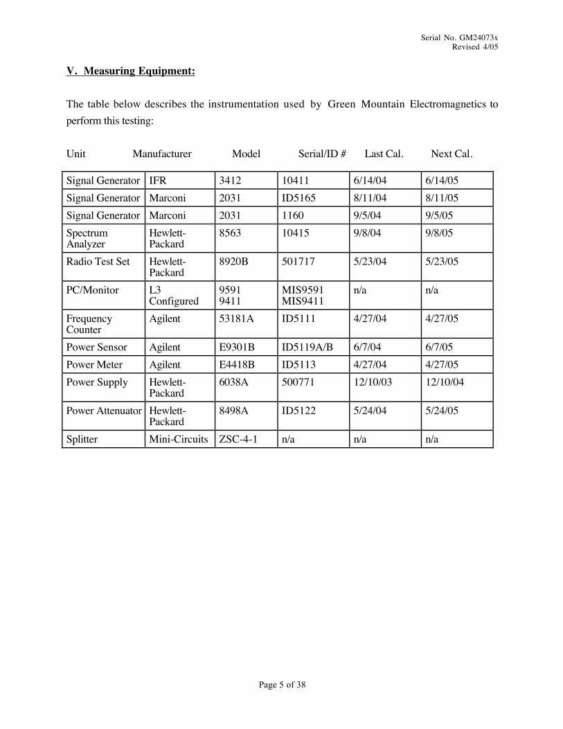
V. Measuring Equipment:
The table below describes the instrumentation used by Green Mountain Electromagnetics toperform this testing:
Unit Manufacturer Model Serial/ID # Last Cal. Next Cal.
Signal Generator IFR 3412 10411 6/14/04 6/14/05Signal Generator Marconi 2031 ID5165 8/11/04 8/11/05Signal Generator Marconi 2031 1160 9/5/04 9/5/05SpectrumAnalyzer
Hewlett-Packard
8563 10415 9/8/04 9/8/05
Radio Test Set Hewlett-Packard
8920B 501717 5/23/04 5/23/05
PC/Monitor L3Configured
95919411
MIS9591MIS9411
n/a n/a
FrequencyCounter
Agilent 53181A ID5111 4/27/04 4/27/05
Power Sensor Agilent E9301B ID5119A/B 6/7/04 6/7/05Power Meter Agilent E4418B ID5113 4/27/04 4/27/05Power Supply Hewlett-
Packard6038A 500771 12/10/03 12/10/04
Power Attenuator Hewlett-Packard
8498A ID5122 5/24/04 5/24/05
Splitter Mini-Circuits ZSC-4-1 n/a n/a n/a
Serial No. GM24073xRevised 4/05
Page 6 of 38
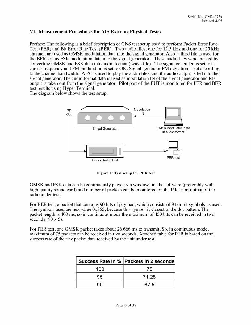
VI. Measurement Procedures for AIS Extreme Physical Tests:
Preface: The following is a brief description of GNS test setup used to perform Packet Error RateTest (PER) and Bit Error Rate Test (BER). Two audio files, one for 12.5 kHz and one for 25 kHzchannel, are used as GMSK modulation data into the signal generator. Also, a third file is used forthe BER test as FSK modulation data into the signal generator. These audio files were created byconverting GMSK and FSK data into audio format (.wave file). The signal generated is set to acarrier frequency and FM modulation is set to ON. Signal generator FM deviation is set accordingto the channel bandwidth. A PC is used to play the audio files, and the audio output is fed into thesignal generator. The audio format data is used as modulation IN of the signal generator and RFoutput is taken out from the signal generator. Pilot port of the EUT is monitored for PER and BERtest results using Hyper Terminal.The diagram below shows the test setup.
GMSK modulated datain audio format
Singal Generator
Radio Under TestPER test
Modulation IN
RFOut
Figure 1: Test setup for PER test
GMSK and FSK data can be continuously played via windows media software (preferably withhigh quality sound card) and number of packets can be monitored on the Pilot port output of theradio under test.
For BER test, a packet that contains 90 bits of payload, which consists of 9 ten-bit symbols, is used.The symbols used are hex value 0x355, because this symbol is closest to the dot-pattern. Thepacket length is 400 ms, so in continuous mode the maximum of 450 bits can be received in twoseconds (90 x 5).
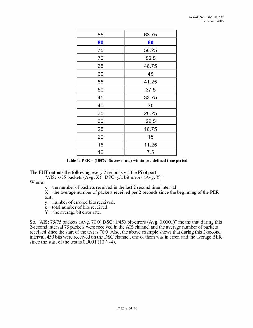
For PER test, one GMSK packet takes about 26.666 ms to transmit. So, in continuous mode,maximum of 75 packets can be received in two seconds. Attached table for PER is based on thesuccess rate of the raw packet data received by the unit under test.
Success Rate in % Packets in 2 seconds
100 75
95 71.25
90 67.5
Serial No. GM24073xRevised 4/05
Page 7 of 38
85 63.75
80 60
75 56.25
70 52.5
65 48.75
60 45
55 41.25
50 37.5
45 33.75
40 30
35 26.25
30 22.5
25 18.75
20 15
15 11.25
10 7.5
Table 1: PER = (100% -Success rate) within pre-defined time period
The EUT outputs the following every 2 seconds via the Pilot port.“AIS: x/75 packets (Avg. X) DSC: y/z bit-errors (Avg. Y)”
Wherex = the number of packets received in the last 2 second time intervalX = the average number of packets received per 2 seconds since the beginning of the PERtest.y = number of errored bits received.z = total number of bits received.Y = the average bit error rate.
So, “AIS: 75/75 packets (Avg. 70.0) DSC: 1/450 bit-errors (Avg. 0.0001)” means that during this2-second interval 75 packets were received in the AIS channel and the average number of packetsreceived since the start of the test is 70.0. Also, the above example shows that during this 2-secondinterval, 450 bits were received on the DSC channel, one of them was in error, and the average BERsince the start of the test is 0.0001 (10 ^ -4).
Serial No. GM24073xRevised 4/05
Page 8 of 38
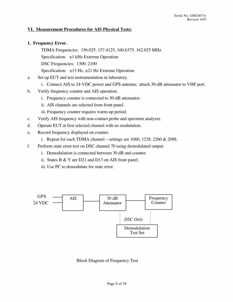
VI. Measurement Procedures for AIS Physical Tests:
1. Frequency Error.TDMA Frequencies: 156.025, 157.4125, 160.6375, 162.025 MHzSpecification: ±1 kHz Extreme OperationDSC Frequencies: 1300, 2100Specification: ±13 Hz, ±21 Hz Extreme Operation
a. Set up EUT and test instrumentation in laboratory.i. Connect AIS to 24-VDC power and GPS antenna; attach 30-dB attenuator to VHF port.
b. Verify frequency counter and AIS operation.i. Frequency counter is connected to 30-dB attenuator.ii. AIS channels are selected from front panel.iii. Frequency counter requires warm-up period.
c. Verify AIS frequency with non-contact probe and spectrum analyzer.d. Operate EUT at first selected channel with no modulation.e. Record frequency displayed on counter.
i. Repeat for each TDMA channel – settings are 1060, 1228, 2260 & 2088.f. Perform state error test on DSC channel 70 using demodulated output.
i. Demodulation is connected between 30 dB and counter.ii. States B & Y are D21 and D13 on AIS front panel.iii. Use PC to demodulate for state error.
AISGPS24 VDC
Block Diagram of Frequency Test
30 dBAttenuator
FrequencyCounter
DemodulationTest Set
DSC Only

Serial No. GM24073xRevised 4/05
Page 9 of 38
VI. Measurement Procedures for AIS Extreme Physical Tests Cont'd:
2. Carrier Power.High Specification: 40.96 +2/-3 dBm (12.5W +7.3W/-6.25W) Extreme OperationLow Specification: 33.01 +2/-3 dBm (2W +1.2W/-1W) Extreme Operation
a. Set up EUT and test instrumentation in laboratory.i. Connect AIS to 24-VDC power and GPS antenna; attach 30-dB attenuator to VHF port.
b. Verify power meter/sensor and AIS operation.i. Power sensor is connected to 30-dB attenuator.ii. AIS power levels are selected from front panel.iii. Power meter requires zeroing and calibration each time.
c. Verify AIS frequency with spectrum analyzer.d. Operate EUT at high power unmodulated.e. Record level displayed on meter.f. Repeat for low power.
AISGPS24 VDC
Block Diagram of Carrier Power Test
30 dBAttenuator
PowerMeter
PowerSensor
SpectrumAnalyzer
Serial No. GM24073xRevised 4/05
Page 10 of 38
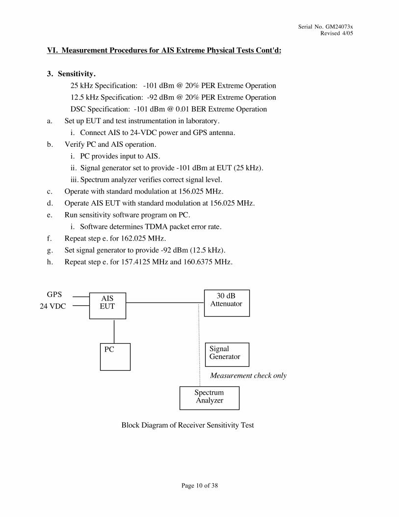
VI. Measurement Procedures for AIS Extreme Physical Tests Cont'd:
3. Sensitivity.25 kHz Specification: -101 dBm @ 20% PER Extreme Operation12.5 kHz Specification: -92 dBm @ 20% PER Extreme OperationDSC Specification: -101 dBm @ 0.01 BER Extreme Operation
a. Set up EUT and test instrumentation in laboratory.i. Connect AIS to 24-VDC power and GPS antenna.
b. Verify PC and AIS operation.i. PC provides input to AIS.ii. Signal generator set to provide -101 dBm at EUT (25 kHz).iii. Spectrum analyzer verifies correct signal level.
c. Operate with standard modulation at 156.025 MHz.d. Operate AIS EUT with standard modulation at 156.025 MHz.e. Run sensitivity software program on PC.
i. Software determines TDMA packet error rate.f. Repeat step e. for 162.025 MHz.g. Set signal generator to provide -92 dBm (12.5 kHz).h. Repeat step e. for 157.4125 MHz and 160.6375 MHz.
AISEUT
GPS24 VDC
Block Diagram of Receiver Sensitivity Test
30 dBAttenuator
SpectrumAnalyzer
PC SignalGenerator
Measurement check only

Serial No. GM24073xRevised 4/05
Page 11 of 38
VI. Measurement Procedures for AIS Extreme Physical Tests Cont'd:
4. Adjacent Channel Selectivity.25 kHz Specification & DSC: >60 dB Extreme Operation12.5 kHz Specification: >50 dB Extreme Operation
a. Set up EUT and test instrumentation in laboratory.i. Connect AIS to PC, 24-VDC power, GPS antenna.
b. Verify PC and AIS operation.i. PC monitors AIS, then sig. gen. A & B are connected to combiner.ii. Signal generator is set to provide -104 dBm at EUT (25 kHz).iii. Signal generator B set to provide -44 to EUT (60-dB result) at channel immediately
above the AIS channel.iv. Spectrum analyzer verifies correct signal level.
c. Operate PC and AIS EUT with standard modulation at default channel.d. Run adjacent-channel software program on PC.
i. Software determines packet error rate from messages.ii. Proceed as in IEC 61993 para. 15.3.6 steps a. – k. if PER >20%.
e. Repeat step d. for channel immediately below AIS channel.f. Repeat steps d. and e. for 12.5-kHz AIS channel.
i. Set signal generator to provide -95 dBm/-50 dBm.g. Repeat step a. – c. for DSC; Generator provides -34-dBm FM modulated at 400 Hz/3kHz.
AISEUT
GPS24 VDC
Block Diagram of Receiver Adjacent-Channel Test
SpectrumAnalyzer
PCSignal
GeneratorA
MeasurementCheck Only
SignalGenerator
B
Combiner
Serial No. GM24073xRevised 4/05
Page 12 of 38
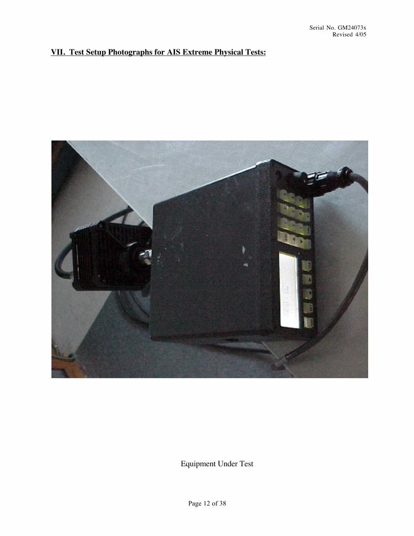
VII. Test Setup Photographs for AIS Extreme Physical Tests:
Equipment Under Test

Serial No. GM24073xRevised 4/05
Page 13 of 38
VII. Test Setup Photographs for AIS Extreme Physical Tests Cont'd:
EUT and Support Equipment for Temperature Tests

Serial No. GM24073xRevised 4/05
Page 14 of 38
VII. Test Setup Photographs for AIS Extreme Physical Tests Cont'd:
Vibration Test Setup

Serial No. GM24073xRevised 4/05
Page 15 of 38
VIII. Measurement Results for AIS Extreme Physical Tests:
1. Frequency Error at Dry Heat and Low Temperature.Frequencies: 156.025, 157.4125, 160.6375, 162.025 MHzSpecification: ±1 kHz Extreme OperationFrequencies: 1300 Hz, 2100 HzSpecification: 1% (13 Hz, 21 Hz) Extreme Operation
Specified MeasuredTemperature SupplyVoltage Channel Frequency(Hz) Frequency(Hz)High High 1060 156,025,000 156,025,085High High 1228 157,412,500 157,412,588High High 2260 160,637,500 160,637,566High High 2088 162,025,000 162,025,058Low Low 1060 156,025,000 156,025,329Low Low 1228 157,412,500 157,412,831Low Low 2260 160,637,500 160,637,814Low Low 2088 162,025,000 162,025,305Low Low D21 2100.000 2100.578Low Low D13 1300.000 1299.317High High D21 2100.000 2100.576High High D13 1300.000 1299.310
Serial No. GM24073xRevised 4/05
Page 16 of 38
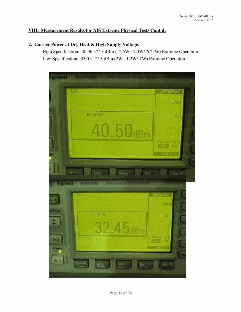
VIII. Measurement Results for AIS Extreme Physical Tests Cont'd:
2. Carrier Power at Dry Heat & High Supply Voltage.High Specification: 40.96 +2/-3 dBm (12.5W +7.3W/-6.25W) Extreme OperationLow Specification: 33.01 +2/-3 dBm (2W +1.2W/-1W) Extreme Operation
Serial No. GM24073xRevised 4/05
Page 17 of 38
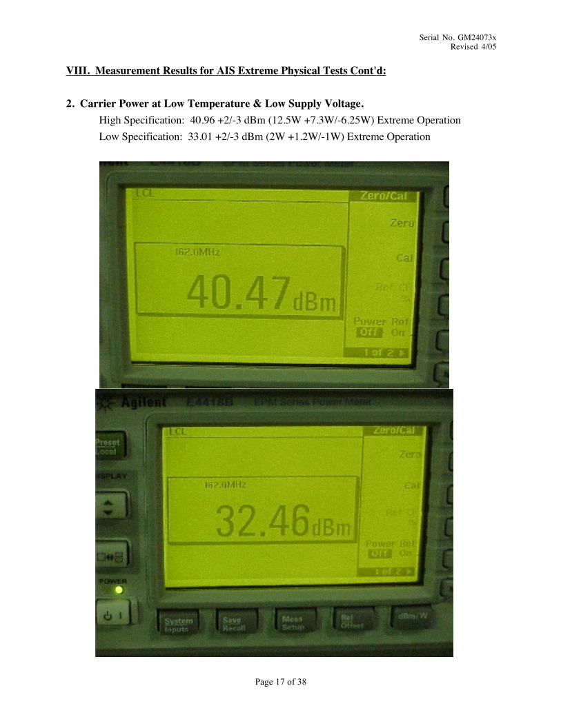
VIII. Measurement Results for AIS Extreme Physical Tests Cont'd:
2. Carrier Power at Low Temperature & Low Supply Voltage.High Specification: 40.96 +2/-3 dBm (12.5W +7.3W/-6.25W) Extreme OperationLow Specification: 33.01 +2/-3 dBm (2W +1.2W/-1W) Extreme Operation