EXTERIOR BALLISTICS. 437 - eugeneleeslover.com
120
EXTERIOR BALLISTICS. 437 Substituting the value of this coefficient, obtained above, in the / formula for the function u, and using for /0 and the differ- ences in this formula the tabular quantities for the function u for the same values of V and Z used in computing the coefficient, u = 1041- .43 X 8+ .59 X 14- 0 = 1045.8 24. Given D' = 11J5 V =3018 Find A". V-Yo -h-=·18 5500 for D' Z-Zo= 125-120.4 = 67 100 7-.18 . Since V is greater than 2500 we must·inspect the table to see how A" varies for the value of Z used. We find that A" is here diminishing with V and increasing with Z. The first of the / formulas is therefore appropriate. A" =3364+ .67X73- .18X6-0=3411.8 25. Given A' =0.0401 Z =51,-0 Find T'. Z-Zo 100 =.4 For Z = 500 this value of A' lies between the values given for V =900 and V =925. Applying the correction for Z to the value corresponding to V = 925, we find that 925 is the proper value of V to use in the formula. V - Vo 418-401 825 h 19+4X.4· T' = (0.548)+.4X 111- .825 X 14- AX .825X3=0.5799 26. Given log B' =0.0809 Z =1J565 Find log C'. Z-Zo 100=·65 V - Vo _ 809-786.65 4 for log B' h - 44+2X .65 . 93 log C' = (5.3076) + .65 X34- .493 X 274- .65 X 0493 X2 = 5.29624 27. Given A' =0.2485 V =2180.4 Find BAns. 0.15578 28. Given T' =7.698 Z =5728 Find D' Ans. 1013.3 29. Given log B' =0.1832 V = 1832 Find u Ans. 954.2 30. Given A =0.01669 Z = 1224.5 Find log C' Ans. 5.1347
Transcript of EXTERIOR BALLISTICS. 437 - eugeneleeslover.com

EXTERIOR BALLISTICS. 437
Substituting the value of this coefficient, obtained above, in the / formula for the function u, and using for /0 and the differences in this formula the tabular quantities for the function u for the same values of V and Z used in computing the coefficient,
u = 1041- .43 X 8+ .59 X 14- 0 = 1045.8
24. Given D' = 11J5 V =3018 Find A".
V-Yo -h-=·18
5500
for D' Z-Zo= 125-120.4 = 67 100 7-.18 .
Since V is greater than 2500 we must · inspect the table to see how A" varies for the value of Z used. We find that A" is here diminishing with V and increasing with Z. The first of the / formulas is therefore appropriate.
A" =3364+ .67X73- .18X6-0=3411.8
25. Given A' =0.0401 Z =51,-0 Find T'.
Z-Zo 100 =.4
For Z = 500 this value of A' lies between the values given for V =900 and V =925. Applying the correction for Z to the value corresponding to V = 925, we find that 925 is the proper value of V to use in the formula.
V - Vo 418-401 825 h 19+4X.4·
T' = (0.548)+.4X 111- .825 X 14- AX .825X3=0.5799
26. Given log B' =0.0809 Z =1J565 Find log C'. Z-Zo 100=·65
V - Vo _ 809-786.65 4 for log B' h - 44+2X .65 . 93
log C' = (5.3076) + .65 X34- .493 X 274- .65 X 0493 X2 = 5.29624 27. Given A' =0.2485 V =2180.4 Find BAns. 0.15578 28. Given T' =7.698 Z =5728 Find D' Ans. 1013.3 29. Given log B' =0.1832 V = 1832 Find u Ans. 954.2 30. Given A =0.01669 Z = 1224.5 Find log C' Ans. 5.1347

CHAPTER X.
PROJECTILES.
257. Classification.-Projectiles are classed as shot, shell, and . case shot. The shell is a hollow shot designed to be filled with a bursting charge that by means of a fuse may be exploded at a selected time. The case shot consists of a number of shot held together by an enclosing envelope which may be ruptured by the shock of discharge or by a bursting charge in flight. The envelopes of canister and grape shot are ruptured by shock in the gun. The envelope of shrapnel is ruptured by a bursting charge.
Old Forms of Projectiles.-In the old smooth bore cannon round cast iron shot and shell of diameter nearly equal to the caliber of the gun were used. The grape, canister, and shrapnel for these
GRAPE. CANISTFR.
guns are shown in the illustratIOns. The shrapnel was invented about 1803 by Colonel Shrapnel of the British Army. In its first form it contained a number of lead balls with loose powder in the interstices. The walls of the shell were made thick to resist deformation by the movement of the contained balls. In its later forms the spaces between the balls were filled with melted sulphur,
438

PROJECTILES. 439
and a chamber for the bursting charge was provided as shown. By this arrangement the walls were no longer subject to the impact from the loose balls, and therefore could be made thinner,
SHRAPNEL.
thus providing room for a greater number of bullets. The confining of the bursting charge in a chamber made its explosive effect greater and permitted a reduction in its weight.
Chain shot and bar shot, made up of two projectiles connected by a chain or bar, were occasionally used in early times; and in-
I I
CD I I I I
CD , ,
STUDDED. EUREKA. BUTLER.
cendiary shell, called carcasses, which were ordinary shell filled with combustible material, the flames from which issued through holes drilled through the walls of the shell.
Smooth bore guns were succeeded by muzzle loading rifled guns. The introduction of rifling brought about the use of elongated projectiles of increased weight. The capacity of the gun in weight of metal thrown was largely increased and much greater accuracy of fire was obtained.
440 ORDNANCE AND GUNNERY.
For the projectiles for the muzzle loading rifled cannon some device was necessary to cause the projectile to take the rifling. The several devices thatwere employed are shown in the illustrations on the preceding page.
The studs on the ' projectile shown in the first figure were fitted into the grooves of the rifling as the projectile was inserted at the muzzle. In the other projectiles shown the parts a are of brass, and in firing were expanded outward into the rifling by the pressure of the powder gases. Other means that were employed are shown in Figs. 167, 168, and 169.
FIG. 167. FIG. 168. FIG. 169.
Fig. 167 shows the Hotchkiss projectile. The parts a and b are of iron and are held apart by the ring of lead c. The gas pressure acting on the part b forced the lead outward into the rifling.
Fig. 168 shows the Whitworth projectile. The bore of the Whitworth gun was a twisted prism of hexagonal cross section as shown in Fig. 169. The projectile was fashioned to fit the bore, its sides being provided with surfaces of a similar prism.
258. Modern Projectiles. BANDlNG.-With the introduction of breech loading in arms of all kinds the problem of giving rotation to the projectile was much simplified As the chamber of the gun is larger than the bore, a projectile provided with a soft metal band, b Fig. 170, of diameter larger than the diameter of the bore, may be inserted through the chamber. On the explosion of the charge the pressure causes the sloping endS d of the lands of the rifling to force their way through the rotating band, causing the band to conform in shape to the section of the rifling, and

PROJECTILES. 441
assuring the proper rotation in the projectile. Af3 the band complete~y fills the cross section of the bore it serves also as a check to prevent the escape of gas past the projectile, and in addition it
--b a
FIG. 170.
serves to center the projectile in the bore, and to determine a fixed position of the projectile when rammed into the gun.
The banding of projectiles is practically the same for all calibers. An· undercut groove, b Fig. 171, is cut around the projectile near the base. A straight band of copper, of cross section as shown at a, is hammered into the groove and completely fills it, as shown at c. The ends of the band are beveled lengthwise and make a scarf joint where they meet. The bands for projectiles of small caliber are solid rings of metal forced into the grooves of the projectile under hydraulic pressure. The bottom of the groove b is scored with vertical cuts into which the copper enters when the band is hammered on. These
e
FIG. 171.
prevent the rotation of the band independently of the projectile. The width of the band depends upon the caliber of the projectile and is greater for the larger calibers. The outer surface of the band is smooth in projectiles for siege and smaller caliber guns. In the Wider bands of the larger projectiles a number of grooves are cut, as shown in section at c, Fig. 170, to diminish the resistance to

442 ORDNANCE AND GUNNERY.
forcing and to provide space for the metal forced aside by the lands of the rifling.
In the latest 6-inch wire wound guns, in which velocities of over 3400 feet have been produced, difficulty has been experienced on account of the tendency of the jointed rotating bands to strip from the projectile during flight, due to the effect of the centrifugal force. A band made by winding a thin copper ribbon on edge and filling the groove has been tried with these projectiles but without success.
It is probable that the method of banding with solid rings seated by hydraulic pressure will ultimately be used with these and with larger projectileS.
259. FORM OF PROJECTILE.-With the exception of the canister all modern projectiles are of the same general shape,a cylindrical body with ogival head. The ogival head is found by experiment to be the most advantageous, as it offers little resistance to the air and at the same time provides enough metal at the point of the projectile to give to the point the requisite strength to perform the work of penetration.
The ogive is struck from a center on a line perpendicular to the axis of the projectile, Fig. 172, and with a radius usually ex-
BODY_
------AXIS_-·----
i ~ OClv(:
Ii:! I'"
I I ~ I I g HEAD. /
. --+-- -----------r--'----I I / I I / II / \I .... II .;.-II .. <J
II 17'
\1 I \I /'t'
" / ~ / ~/
FIG_ 172_
pressed in calibers. The radius of the head varies m different projectiles from 1! to 3 calibers.
The lower part of the ogive is turned off to make a cylindrical bearing surface for the front part of the projectile. This surface,

PROJECTILES. 443
called the bourrelet, has a diameter 1/100 of an inch less than the diameter of the gun.
Below the bourrelet the diameter of the projectile is diminished, for ease of manufacture and to prevent bearing in the gun, to about 7/100 of an inch less than the caliber. The band is placed from I! to 2t inches from the base, depending on the caliber, the greatest diameter of the band exceeding the caliber by from 1/10 to 3/10 of an inch.
The length of projectile varie3 between 2t and 5 calibers. The length of most of the seacoast projectiles is 3t calibers.
Canister.-Canister projectiles are for use at very short range. when the guns of a battery are being charged by the enemy. The projectile consists of a number of small balls contained in a metallic envelope so constructed that it will break into pieces at the shock of discharge. In our service, canister are provided for the mountain guns only. The canister for the 75 mlm Vickers Maxim gun is shown in Fig. 173.
The case, c, made of malleable iron, is solid =""'===:;8:=== at the bottom and open at the top. It is weakened by two series of cuts, 8, each series consisting of three oblique cuts, each of which extends over an arc of 120 degrees. The case contains 244 iron balls i of an inch in diameter
c
and weighing 30 to the pound. The balls are ~ confined in the case by the tin cup, a, riveted in. Three holes, h, drilled through the bottom of the case admit the powder gases to assist in rupturing the case. The metallic cartridge case is attached to the projectile by being crimped at several points into the groove r.
--b
The copper band, b, forms a stop for the '-----'---'-_..L:..:..~---r head of the cartridge case, and serves as a FIG. 173.
gas check in the gun. The groove g, in other projectiles, is filled with grease for the purpose of preventing the entrance of moisture into the cartridge case.
rt is the present intention of the Ordnance Department not to

444 ORDNANCE AND GUNNERY.
manufacture any more canister. Their place will be taken by shrapnel, which are so constructed that they may be burst within 25 feet of the muzzle of the gun.
260. Sbrapnel.-The modern shrapnel is a projectile designed to carry a number of bullets to a distance from the gun and there to discharge them with increased energy over an extended area. It is particularly efficacious against troops in masses and is not used against material. The shrapnel is the principal field artillery projectile. It is also provided for mountain and siege artillery and for use in the small caliber guns in seacoast fortifications in repelling land attacks.
In the earlier models the case of the shrapnel was so constructed as to break into a number of fragments on explosion of the bursting charge, with the idea of thus practically increasing the number of bullets carried. With the same end in view the spaces between the balls were filled with the parts of cast metal diaphragms that separated the layers of balls and broke up into additional fragments at the bursting of the projectile. The bUrsting charge was placed sometimes in the head and sometimes in t,he base of the projectile. It was found with these shrapnel that a very large percentage of the numerous fragments had not sufficient energy to . inflict serious injury. The shrapnel is therefore at present constructed of a stout case which, except for the blowing out of the head, remains intact at the explosion of the burSting charge, and from which the balls are expelled in a forward dire~tion and with increased velocity by the bursting charge in the base. By these means, while the number of fragments is less, a greater number possess the required energy and the effective range of these is increased.
Fig. 174 represents the shntpnel for the 3-inch field gun. The case, c, is a steel tube drawn in one piece with a solid base. A steel diaphragm, d, rests on a shoulder near the base, forming a chamber for the bursting charge in the base of the projectile, and a support for a central steel tube which extends through the head, h. A small quantity of guncotton in · the bottom of the tube is ignited by the flame from the fuse, and in turn ignites the bursting charge. The balls, of lead hardened
. with antimony, are 252 in number. Each ball is 49/100 of an

PROJECTILES. 445
jnch in diameter and weighs approximately 167 grains, or 42 to the pound. After the balls are inserted a matrix of mono-nitronaphthalene is poured into the case, filling the interstices between the balls in the lower half of the case. When cool this substance is a waxy solid. It gives off a dense black smoke in burning. The purpose of its introduction is to render the burst of the shrapnel visible from the gun so that the ~.,...,......~I gun commander may determine whether his projectiles are attaining the desired range. Resin is used as the matrix in the forward half of the case.
The matrix forms a solid mass with the balls and prevents their deformation by the pressure that they would exert upon each other, on the shock of discharge in the gun, if they were loose in the case. Resin gives better sgpport to the balls than naphthalene and the~efore no more of the naphthalene is used than is necessary to produce the desired amount of smoke.
On being expelled from the case the ' matrix burns and breaks up, leaving the '--------'
FIG. 174. balls free.
To prevent rotation of the contained mass in the case the interior of the case is fluted lengthwise, so that its cross section is as shown
in Fig. 175; and to reduce the friction to a minimum, particularly in the chamber for the bursting charge, the interior of the case is coated with a smooth asphalt lacquer.
The head, h, of steel is given a cellular form to make it as light as possible. The weight of
FIG. 175. the projectile complete is fixed at 15 lbs., and weight is saved as far as possible in all parts of
the case in order that the greatest number of balls may be carried. The head is screwed into the body and fixed by two brass pins, p. The combination time and percussion fuse, I, is screwed into the

446 ORDNANCE AND GUNNERY
head. It is protected against injury or tampering by the spun brass cap, b, soldered on to the head of the projectile.
The projectile is fixed in the cartridge case as explained for the canister.
Shrapnel forms 80 per cent of the ammunition supply of the field g~n.
261. The Bursting of Shrapnel.-When the shrapnel bursts the balls are expelled forward with increased velocity, and as they have at the same time the movement of rotation of the projectile they are dispersed more or less to the right and left. Their paths form a cone, called the' cone of dispersion, about the prolongation of the trajectory. The section of this cone at the ground is an irregular oval with its longer axis in the plane of fire. The dimensions of the area will vary, as is evident from Fig. 176, with the
FIG. 176.
angle of fall, the height of burst, and the relation between the velocities of translation and rotation at the moment of burst.
It is assumed that when a shrapnel ball has an energy of 58 foot pounds it has sufficient force to disable a man, and with 287 foot pounds of energy it will disable a horse. These energies correspond in the service shrapnel bullet to velocities of about 400 and 880 foot seconds. An increased velocity of from 250 to 300 feet is imparted to the balls by the bursting charge. Knowing the velocity of the projectile and the weight of the balls the space within which the balls will be effective may be determined for any range.
POINT OF BURST.-The best point Qf burst for a shrapnel is assumed to be that point from which the burst of the shrapnel will produce practically one hit per square yard of vertical surf ace at the target. It is determined from the cone of dispersion by finding the right section that contains as many square yards as there are bullets in the shrapnel. The distance in front of the target at which the burst occurs is called the interval 0/ burst. On a,o..

PROJECTILES. 447
count of the variation at different ranges in the velocities of translation and of rotation the interval of burst which will produce one hit. per square yard of vertical surface at the target varies with the · range, decreasing as the range increases.
Practically it is found best to consider the height of burst rather than the interval of burst, since the battery commander can more readily estimate the height than the interval. Suitable cross hairs in the field of the battery commander's telescope facilitate this estimation.
In our service a height of 3/1000 of the range, called 3 mils, is adopted as the most favorable mean height of burst. The point of burst at this height gives, over a large part of the range, very approximately the correct interval of burst. For short ranges this height of burst is excessive, and for long ranges it is insufficient.
The follo~g table shows for the 3-inch shrapnel the results obtained at different ranges from bursts at the correct interval of burst, and also at a height of burst of 3 mils. The front of target that should be covered depends upon the number of balls in the shrapnel For the 3-inch shrapnel with 270 bullets, a former model, the front to be covered with one hit per square yard is 18.5 yards.
One Hit per Square Yard . Height of Burst, 3 Mils.
Range.
Interval. Front Covered. Interval. Front Covered. ---- --------- -~--------
Yards. Yards. Yards. Yards. Yards. 1000 ~\l.4 11>.5 111j.~ ~7.0 2000 73.0 18.5 83.4 21.2 2.500 68.98 18.5 73.5 19.55 3000 65.84 18.5 66.6 18.76 3500 63 .28 18.5 60.9 18.84 4000 61.07 18.5 56 .4 17.12 4500 58.97 18.5 51.3 16.13
It will be observed that between 2000 and 4500 yards the height of burst of 3 mils gives approximately the desired density of fire at the target. At ranges less than 2000 yards the front covered is largely increased and the density of fire therefore diminished.
The figures refer to a single shrapnel bursting at the mean

448 ORDNANCE AND GUNNERY.
point of burst. In a group of shrapnel the bursts above and below the mean point would largely make up the discrepancies in distribution and density.
FusE.-The fuse used in the shrapnel is the combination time and percussion fuse of which a full description will be found in the chapter on fuses. The fuse is arranged in such a manner that if the projectile is not burst in flight it will be burst soon after impact, a short time being allowed by the delay element in the fuse, during which the projectile may rise on a graze and its burst be accomplished in the air.
The fuse is also constructed to permit of using the shrapnel as canister. When the fuse is set at zero of the time scale, the projectile will burst within 25 feet of the muzzle of the gun.
262. Shot and Shell.-Solid shot are no longer used in modern cannon except for .target practice, at least in our service. Certain hollow projectiles with thick walls designed principally for the perforation of armor are denominated shot to distinguish them from shell, which name is given to thinner walled projectiles that have not as great a penetrative power but carry larger bursting charges, and have consequently greater destructive effect after penetration.
Shell were formerly made of cast iron, being cast in one piece and subsequently bored for the fuse, Fig. 177.
FIG. 177.
With the adoption of high explosives for bursting charges, greater strength in the walls of shell became desirable in order to insure against accidental explosion of the projectile while in the gun. With the exception of some of the projectiles for guns of minor caliber in which black powder is used for the bursting charge, all projectiles are now made of forgM steel.
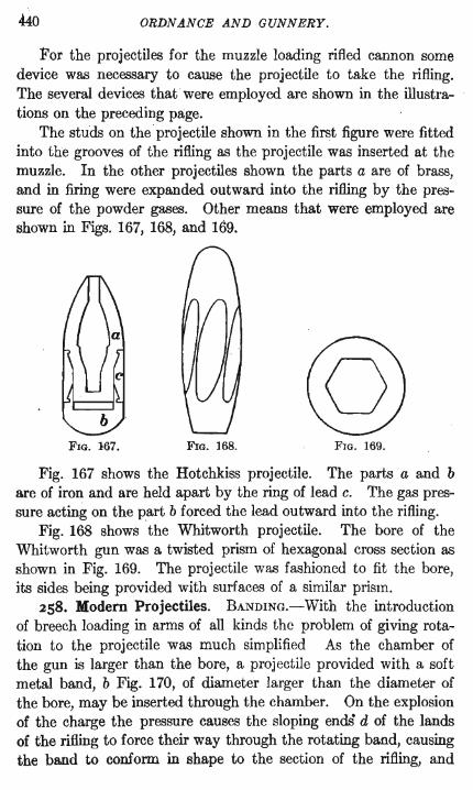
Fig. 178 represents a steel shell for the 5-inch siege rifle. The steel projectiles for mountain, field and siege artillery are similarly constructed.
PROJECTILES. 449
The base of the shell is closed by a steel base plug, p, which is screwed in after the explosive charge has been packed in the projectile. The plug is bored and tapped for the base fuse, I, which when inserted is flush with the rear surface of the projectile. The wrench holes in base plug and in head of fuse are filled with lead in order to make a continuous bearing surface for the copper cup, c. The cup is applied to the oo.se of the shell to prevent the powder gases in the gun from penetrating to the interior of the projectile by way of the joints of the screw threads. The edge of the cup
c--~ __ ......L------~
FIG. 178.
fits into the circular undercut groove, g, and the joint there is sealed and the cup held in place by lead wire hammered in.
Armor Piercing Projectiles.-Armor piercing projectiles are of the same general construction as the steel shell just described. Their distinguishing feature is a soft metal cap embracing the point of the projectile for the purpose of increasing the power of the projectile in the perforation of hard armor.
The head and point of an armor piercing projectile are extremely hard, the hardness being attained in the process of manufacture by anyone of several secret tempering processes. The metal of the projectile before being subjected to the secret process has a tensile strength of about 85,000 pounds per square inch, which is undoubtedly increased by the tempering. The cap, on the other hand, has a tensile strength not exceeding 60,000 pounds, with a large percentage of elongation, and reduction of area, as may be seen in the table on page 165. The metal of the cap is therefore very soft compared with the metal in the head of the projectile.
A lO-inch armor piercing shot is shown in Fig. 179 and a winch shell in Fig. 180.
The shot has thicker walls and head, and a less capacity for

450 ORDNANCE AND GUNNERY.
FIG. 179. FIG. 180. l()..in. Armor Piercing Shot. to-in. Armor Piercing Shell.

PROJECTILES. 451
the bursting charge. The outer diameters of the two projectiles are the same, and the weight of each when ready for firing is the same, 604 pounds. To maintain uniformity of weight the shot is made about 41 inches shorter than the shell.
The cap is fixed to the head of the projectile by means of the circular groove, a, cut around the head of the projectile. The cap before affixing is of the shape shown half in section and half in elevation in the figure between the projectiles. A shallow recess, b, is filled with graphite to lubricate the projectile as it passes through the cap and armor. To fasten the cap, the projectile with the cap on its point is put in a lathe, and the excess metal at the base of the cap is hammered into the groove of the projectile by means of pneumatic hammers.
In naval projectiles the caps are sometimes fastened on by passing two wires through holes drilled in the cap and notches cut in the projectile.
263. Action of the Cap.-The soft steel cap increases the power of penetration to the oFojt>ctile in hard faced armor, at
FIG. 181.
normal impact and up to an angle of 30 degrees from the normal, about 15 per cent with respect to the velocity of the projectile and more than 20 per cent with respect to the thickness of plate.
Among the several theories advanced as to the action of the cap, the following appears the most satisfactory. .
When an uncapped projectile strikes the extremely hard face of a modern armor plate, the whole energy of the projectile is applied at the point, and the high resistance of the face of the plate puts upon the very small area at the point of the projectile a
452 ORDNANCE AND GUNNERY.
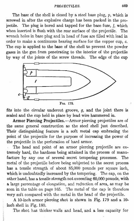
stress greater than the metal can resist, however highly tempered it may be. The point is therefore broken or crushed and the head Of the projectile flattened, Fig. 181. The flattening of the head brings loss of penetrative power, and the energy of the projectile is expended largely in shattering the projectile itself. The head of the projectile adheres to the plate and is practically welded to it.
The effect on a plate of thickness equal to the caliber of the projectile may be the partial or complete punching out of a cylin
drical piece, Fig. 182. But even if the plate is completely perforated, the projectile does not get through as a whole; and behind the plate are found only fragments of the projectile and of the metal forced from the
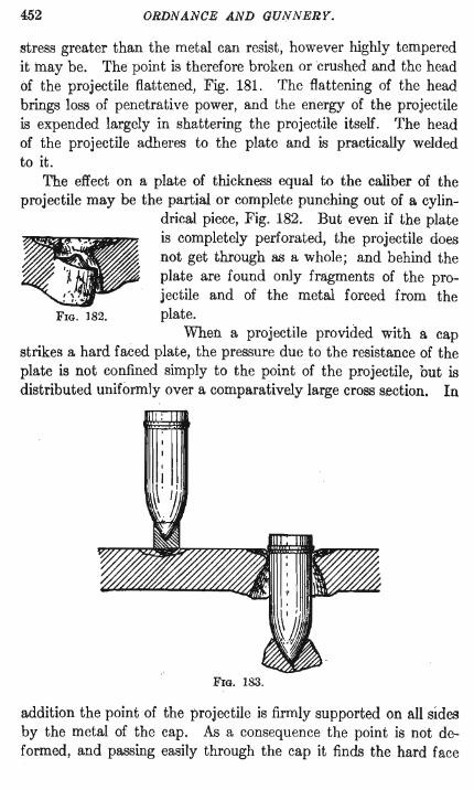
FIG. 182. plate. When a projectile provided with a cap
strikes a hard faced plate, the pressure due to the resistance of the plate is not confined simply to the point of the projectile, but is distributed uniformly over a comparatively large cross section. In
FIG. 183.
addition the point of the projectile is firmly supported on all sides by the metal of the cap. As a consequence the point is not deformed, and passing easily through the cap it finds the hard face

PROJECTILES. 453
of the plate dished and severely strained and more or less crumbled by the impact of the cap. The unexpended energy of the projectile forces the point through the weakened face and through the softer metal of the back.
The face of the plate is crumbled, and a conical hole made through the softer metal, through which the projectile passes practically intact and in condition for effective bursting, Fig. 183.
The form of the cap has not apparently a great effect on the results. Many different shapes are used by different manufacturers, some of which are shown in Fig. 184.
FIG. 184.
The cap increases the biting angle of the projectile, the li:niting angle of impact at which the projectile will perforate the plate.
The following results have been obtained in comparative tests of capped and uncapped projectiles against tempered nickel .steel plates. The angle of impact is measured from the normal to the plate. .;
Thick- A~fle Strik-Gun. ness of ing Ve- J:'rpjectile. Effect.
Plate. Impact. locity.· ----
Inches. Degrees 8-inch rifle. .. ... 3.5 60 1074 Capped Perforated Palate
. .... . 60 1073 Uncapped Indented pate! inch
... ... 6.5 1066 Capped Perforated plate
. ..... 65 1077 Uncapped Indented plate It inches 12-inch mortar ... 4 .5 40 711 Capped Nearly perforated. In-
dentation 6 inches deep. Fragment nearly punched out·
. . .... {O 711 Uncapped Glanced from plate. In-dentation I i inches deep
It is stated that the addition of the cap to the projectile and· the consequent' moving of the center of gravity of the projectile

454 ORDNANCE AND GUNNERY.
toward the point favorably influences the trajectory, increasing both the accuracy and range.
All projectiles for seacoast guns above 3 inches in caliber will probably be provided with caps.
264. Deck Piercing and Torpedo Shell.-These projectiles are provided for the 12-inch mortars. The torpedo shell is longer and of greater interior capacity th~m the deck piercing shell, and carries a larger bursting charge of high explosive. The bursting charge for the deck piercing shell is 64 pounds and for the torpedo shell 134 pounds.
Latest Form of Base of Shell.-A form of base with which good results have been obtained is shown in Fig. 185. The metal
FIG. 185.
of the shell is cut away, beginning at a short distance behind the band, leaving only a narrow ring to support the band. In the perforation of armor the band and the supporting ring are sheared off, thus relieving the projectile of the resistance due to the greater diameter of the band.
Shell Tracers.-Experiments are now being conducted toward the development of a projectile that will indicate its line of flight by the emission of flame, or by the emission of some
substance that will be visible from the gun; the purpose of the projectile being to enable the gun commander to follow the flight of a projectile from his gun and thus determine whether the gun is properly directed.
The tracer for use at night consists of a short metal cylinder filled with a slow burning substance that emits a bright flame during the flight of the projectile through the air. It may be screwed into a seat prepared in the base of any projectile. Ignition of the compound occurs in the gun.
For day tracing a special shell is prepared. The cavity of the shell is partly filled with a mixture of lampblack and water, the mixture having the consistency of thick paint. A small orifice is made through the base of the projectile on one side. The powder gases enter this orifice under the pressure in the gun, and filling the cavity in the shell force from the orifice during flight a spray of

PROJECTILES, 455
black liquid. In recent experiments the flight of a 6-inch day tracing shell was followed for over 7200 yards.
Hand Grenades.-The hand grenade is a metal bomb filled with high explosive and provided with one or more percussion caps or fuses, which cause .its explosion on striking after being thrown. Hand grenades were effectively used by both sides in the RussoJapanese war.
265. Volumes of Ogival Projectiles.-Assume a solid cylinder, Fig. 186, of the length and diameter of a given solid shot.
Let d represent the diameter of the shot, usu- -i-,----.,...---, ally taken as equal to the caliber of ! the gun,1
L, the length of the shot in calibers. I The volume of the cylinder is (11:d2 /4)Ld. ! Let B represent, in calibers, the length ofa Ld
cylinder whose diameter is d and whose volume, I (11:d2 /4)Bd, is equal to that part of the cylinder ! in Fig. 186 that is outside the shot. I
Subtracting this volume from the volume ofl the whole cylinder and representing by V. the _LL.-__ '" volume of the solid shot, we have FIG. 186.
rrd2 rrd3 Y.=--(L-B)d= -(L-B) 4 4
(L-B)d, or L-B calibers, is the length of a solid cylinder whose diameter is the diameter of the shot and whose volume is equal to the volume of the shot. L - B is called the reduced length of the projectile in calibers, as it is the length of· a cylinder of equal diameter and volume.
B is a function of the radius of the ogive expressed in calibers. Its value, obtained by means of the calculus, is given by the equation
in which n is the radius of the ogive in calibers. When n=2, the usual radius of head in seacoast projectiles, B=O.58919.
456 ORDNANCE AND GUNNERY.
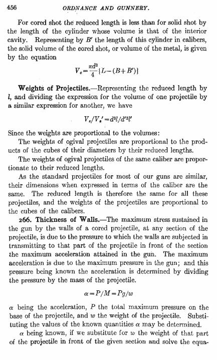
For cored shot the reduced length is less than for solid shot by the length of the cylinder whose volume is that of the interior cavity. Representing by B' the length of this cylinder in calibers, the solid volume of the cored shot, or volume of the metal, is given by the equation
Weights of Projectiles.-Representing the reduced length by l, and dividing the expression for the volume of one projectile by a similar expression for another, we have
V./V.' =d3l/d'3l'
Since the weights are proportional to the volumes: The weights of ogival projectiles are proportional to the prod
ucts of the cubes of their diameters by their reduced lengths. The weights of ogival projectiles of the same caliber are propor
tionate to their reduced lengths. As the standard projectiles for most of our guns are similar,
their dimensions when expressed in terms of the caliber are the same. The reduced length is therefore the same for all these projectiles, and the weights of the projectiles are proportional to the cubes of the calibers.
266. Thickness of Walls.-The maximum stress sustained in the gun by the walls of a cored projectile, at any (3ection of the projectile, is due to the pressure to which the walls are subjected in transmitting to that part of the projectile in front of the section the maximum acceleration attained in the gun. The maximum acceleration is due to the maximum pressure in the gun; and this pressure being known the acceleration is determined by dividing the pressure by the mass of the projectile.
a=P/M=Pg/w
a being the acceleration, P the total maximum pressure on the base of the projectile, and w the weight of the projectile. Substituting the values of the known quantities a may be determined.
a being known, if we substitute for w the weight of that part of the projectile in front of the given section and solve the equa-

PROJECTILES. · 457
tion for P, the value obtained, which we will call PI, will be the pressure sustained by the walls of the section. The area of the section is 7r(R2_ r2). The pressure per unit of area is therefore PI divided by 7r(R2_ r2).
This pressure must not exceed the elastic limit of the metal for compression, divided by a suitable factor of safety; nor must it cause excessive flexure in the walls. If it does the walls must be made thicker.
Thickening the walls will increase the weight in front of the section and therefore a new value of w must be obtained for a. second determination.
In shrapnel it is desirable to make the walls as thin as possible in order to increase the number of bullets that may be carried. The longitudinal pressure of the contained bullets is borne by the thicker base of the projectile, and the walls sustain only the pressure due to the centrifugal force and that proceeding from the weight of the head and fuse. Their thickness will therefore be determined by the requirement that they must resist rupture by· the pressure exerted by the gases from the bursting charge when the head of the proj~ctile is blown off. The pressure required to blow off the head is equal to the resistance offered to shearing by the screw threads and shear pins of the head.
A much greater thickness of wall than is needed in the gun is required to enable a projectile to withstand the shock of impact on the face of an armor plate. The retardation in this case is much greater than the acceleration in the gun and consequently the stresses on the walls are correspondingly greater. As there is no means of determining the retardation at impact, the proper thickness of walls of armor piercing projectiles cannot be calculated, but must be determined by experiment.
We may, however, by assuming that the plate offers a constant resistance to the penetration of the projectile, determine the thickness of wall necessary in the projectile to enable it to pass through the plate and have any required velocity on emerging.
Thus, to determine the thickness of wall of an armor piercing sh~ll that is required, with a striking velocity v, to perforate an armor ·plate of given thickness and to have on emerging a remaining velocity VI.

458 ORDNANCE AND GUNNERY.
Let S be the constant resistance offered by the plate l the thickneS!' of the plate, in feet,
a the constant retardation of the projectile during pene-tration.
The work performed by the resistance over the path l is equal to the energy abstracted from the projectile while traversing this path. Therefore
M Sl=-(v2- V12)
2
The retardation due to the resistance is equal to the resistance divided by the mass. Therefore
The pressure sustained by any section of the projectile durfng penetration is equal to the mass of that portion of the projectile behind the section multiplied by the retardation. Denoting by w' the weight of that part of the projectile behind any given section, we have for the pressure sustained per unit of area at the section
w' a W'(v2-V12) p= g x(W-r2) 2lgx(R2-r2)
R and r must be given such values, that is, the thickness of the walls must be such that p will not exceed the elastic limit of the metal for compression, or that the flexure ·of the walls, considering the shell as a hollow column, will not be sufficient to cause rupture.
267. Sectional Density of Projectiles.-It has been found by experiment, as explained in exterior ballistics, that the retardation in the velocity of a fired projectile, due to the resistance of the air, is expressed by an equation that, for any fixed atmospheric conditions and standard form of projectile, may be put in the form
d2 R=A-J(v) w
R representing the retardation, A a constant, d the diameter of the projectile, w its weight, and I(v) some function of its velocity.

PROJECTILES. 459
For a given velocity it is apparent that the retardation will increase directly with the square of the diameter of the projectile and inversely with its "Yeight; or, more concisely, the retardation will increase directly with the fraction d2/w.
The reciprocal of this fraction, or w/d2, will therefore be the measure of the capacity of the projectile to resist retardation, that is, to overcome the resistance of the air.
The fraction w/d2 is called the sectional density of the projectile. w/tnd2 is the weight of the projectile per unit area of cross section, and w/d2 is taken as the measure of this weight, n/4 being coni3tant.
The sectional density is of importance in considering the motion of the projectile both in the air and in the gun.
EFFECT ON THE TRAJECTORY.-The greater the sectional density of the projectile, the less the value of its reciprocal, the factor d2 /w in the above equation, and consequently the less is the value of the retardation of the projectile.
Of two projectiles fired with the same initial velocity and elevation, the projectile with the greater sectional density will therefore lose its velocity more slowly and will attain a greater range. For any given range it will be subjected for a less time to the action of gravity and other deviating causes, and will therefore have a Batter traj ectory and greater accuracy.
The advantages of increased sectional density are therefore increased range, greater accuracy, and a Batter trajectory.
The sectional density may be increased by increasing the weight of the projectile or by decreasing its diameter. The weight of a projectile for any gun may be increased by increasing its length. This has been done with modern projectiles for large guns until the length is from 3!- to 4 calibers. In small arms the weight is increased by the use of lead in the bullet. Increase in sectional density by decrease in diameter is found in the modern small arms of reduced caliber, the weight and diameter of the projectile having been reduced in such proportions as to increase its sectional density.
EFFECT ON THE GUN,-An increase in the weight of the projectile requires an increased pressure in the bore of the gun if the initial velocity is to be maintained. The maximum pressure for

460 ORDNANCE AND GUNNERY.
any gun being fixed, it has been possible to increase the weight and sectional density of projectiles only by the use of improved powders, which while they exert no greater maximum pressures exert higher pressures along the bore of the gun. The mean pressure on the projectile is therefore greatly increased, and to withstand the increased pressure the chase of the gun is made stronger.
MANUFACTURE OF PROJECTILES.
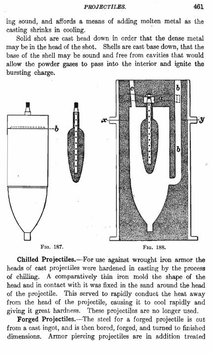
268. Cast Projectiles.-A wooden pattern of the shape of the projectile is first made, the dimensions of the pattern being slightly greater than the dimensions desired in the projectile, in order to allow for contraction of the metal in cooling. The pattern is in one or more parts, depending upon its size. The pattern shown in Fig. 187 is in two parts separated at the line b. The parts are slightly coned from this line to facilitate withdrawal from the mold. For hollow projectiles a core box is also made similar in its interior dimensions to the cavity in the shell. The core, e Fig. 187, made of core sand mixed with adhesives, is formed in the core box around a hollow metal spindle wound with tow. · The heat of the casting burns the tow, and the gases from the core pass out through the hollow spindle.
Fig. 188 shows a mold prepared for casting a shell. The outer box, called the flask, is in two sections parting at the line xy. In the lower part the sand is molded around the pattern, which is also divided into two parts on the same line. In the upper part of the flask the remainder of the mold is made and the core attached in its proper position by means of the frame a bolted to the flask. The gate b and the riser c are also formed in the mold, the riser being considerably greater in diameter than shown in the figure. The patterns are withdrawn and the parts of the mold brought together a;nd bolted.
The molten metal enters through the gate b, generally in a tangential direct ion, so that the metal in the mold has a circular motion which assists in the escape of the gases and brings the impurities to the center and top. The mold is filled with the metal to the top of the riser, where the impurities collect. The pressure of the liquid metal in the riser assists in making the cast-
PROJECTILES. 461
ing sound, and affords a means of adding molten metal as the casting shrinks in cooling. .
Solid shot are cast head down in order that the dense metal may be in the head of the shot. Shells are cast base down, that the base of the shell may be sound and free from cavities that would allow the powder gases to pass into the interior and ignite the bursting charge.
----------- -- --b
FIG. 187. FIG. 188.
Chilled Projectiles.-For use against wrought iron armor the heads of cast projectiles were hardened in casting by the process of chilling. A comparatively thin iron mold the shape of the head and in contact with it was fixed in the sand around the head of the projectile. This served to rapidly conduct the heat away from the head of the projectile, causing it to cool rapidly and giving it great hardness. These projectiles are no longer used.
Forged Projectiles.-The steel for a forged projectile is cut from a cast ingot, and is then bored, forged, and turned to finished dimensions. Armor piercing projectiles are in addition treated

462 ORDNANCE AND GUNNERY.
with some secret process of tempering to give them the hardness and toughness necessary for the perforation of armor.
269. Requirements in Manufacture.-The qualities of the metal of the projectile are prescribed as follows: For cast iron, tensile strength 27,000 Ibs. per square inch; for steel, in what are called oommon shell, that is, those of the smaller calibers, tensile strength 85,000 100. For armor piercing projectiles the tensile strength or elastic limit is not specified, further than by the requirement that the projectiles in a lot shall not vary in tensile strength by more than 20,000 lbs. The strength of these shells is determined by actual firing against armor. The cap must be of steel whose tensile strength does not exceed 60,000 lbs., with an elongation at rupture of 30 per cent, and a reduction in area of 45 per cent.
The base plugs of all projectiles are made of forged steel. Inspection of Projectiles.-The dimensions of the projectiles
are tested by means of calipers, and profile and ring gauges. The slight variations, called tolerances, allowed from the standard rumensions are specified for each dimension, and the gauges' for any projectile are constructed for the maximum and minimum of the partiCUlar dimension . Thus for the diameter of the band there are two ring gauges, one a maximum, the other a minimum, and similarly for other diameters. Maximum and minimum plug gaugeB are applied to the threads of the fuse hole. A ring gauge is shown in Fig. 189. A profile gauge or templet is shown at a in Fie;. 190.
FIG. 189. FIG. 190.
Eccentricity in the cavity of the projectile is determined by rolling the projectile along two rails, a Fig. 191, placed on a flat surface. Irregular · movement of the projectile denotes eccentricity, which may be measured by means of the calipers, d, shown in the figure.

PROJECTILES. 463
For the detection of holes or cracks through the walls of hollow . projectiles all such projectiles are subjected to an interior hydraulic pressure. A pressure of 500 Ibs. per sq. in. is applied for one minute to steel projectiles, and a pressure of 300 Ibs. for two minutes to those of cast iron.
To determine whether the treatment received by the armor piercing shot in the tempering process has left in the shot initial strains that might cause rupture in store or in firing, these shot are cooled to a temperature of 40 degrees F. and then suddenly heated
--a
FIG. 191.
by being plunged into boiling water. When thoroughly heated by the water, the projectile is suddenly cooled by being half inserted,
. with its axis horizontal, in a bath of water at 40 degrees F. After a brief interval it is turned 180 degrees for a like immersion of the other half. Three days must elapse after the tempering of the projectile before this test is applied. The necessity of the test is indicated by the not infrequent bursting of the projectiles in the shops after tempering. This test is not~applied to armor piercing shell. The thinner walls of these projectiles are more uniformly affected by the tempering process.

464 ORDNANCE AND GUNNERY.
The interior walls of hollow projectiles are coated with a lacquer of turpentine and asphalt for the purpose of making them smooth and of reducing the friction between the walls and the bursting charge.
Ballistic Tests.-Each class of projectile is subjected to a - allistic test under conditions assimilating the conditions of ser-
. vice. For the purpose of the test two or more projectiles are selected from each lot pre~ented. The projectiles tested are filled with sand in place of a bursting charge, and after the test must be in condition for effective bursting.
Armor piercing shot are fired against hard faced Krupp armor plate, from 1 to It calibers thick, secured to timber backing. The striking velocities of the shot from 8, 10, and 12 inch rifles against plates one caliber thick are near to 1750 feet, which corresponds to ranges of about 3000, 4000, and 5000 yards, respectively, from the three guns. The shot is required to perforate the plate unbroken and then be in condition for effective bursting.
Armor piercing shells must meet similar conditions, the thick_ ness of the plate being one half the ca~iber of the shell, and the striking velocities, 1420 f. s. for 5-inch shell, 1220 f. s. for 6-inch shell, and 920 f. s. for 8-, 10-, and 12-inch shell.
12-inch deck piercing shell must perforate a 4!-inch nickel steel protective deck plate at an angle of impact of 60 degrees.
12-inch torpedo shell are fired into a sand butt from a gun in which the chamber pressure must be 37,000 lbs.
Common steel shell for seacoast guns of small caliber are tested with service velocities against tempered steel plates from 3 to 5 inches thick, depending on the caliber and service velocity of the projectile.
The shell for field and mountain guns are fired into sand, with a pressure in the gun 12 per cent greater than the service pressure and with at least the service velocity.
Tests are also made to determine whether the fragmentation of the projectile on bursting is satisfactory.
The Painting of Projectiles.-Projectiles ar(~ so painted as to indicate the metal of which they are formed and the character of the bursting charge. The greater part of the body is black. A broad colored band around the projectile over the center of gravity

PROJECTILES. 465
indicates by the color whether the projectile is of iron, cast or chilled, or of steel, cast or forged.
The color of the base indicates whether the projectile is charged with powder or with high explosive. In assembled ammunition the base color is painted in a band just above the band of the ~oo~ .

CHAPTER XI.
ARMOR.
270. History.-The use of armor for ,the protection of ships of war began in France in 1855 and soon became general. The first armor was of wrought iron. This metal opposed a sufficient resistance to the round cast iron projectiles of that time and to the elongated cast iron shot of a later date. As the power of guns increased and chilled projectiles came into use wrought iron armor became ineffective. It was replaced about 1880 by compound armor, which consisted of a wrought iron back and a hard steel face. Compound armor was made either by running molten steel on the previously prepared wrought iron back or by welding a plate of steel to another of wrought iron by running molten steel between them, both plates being previously brought to a welding heat. The hard steel face opposed a great resistance to penetration of the shot and caused the shot to expend its energy in shattering itself. At the same time it distributed the stress over an increased section of the iron back, and the toughness of the wrought iron served to hold the plate together. The chief defect of the compollnd plate was due to the difficulty of obtaining intimate union between the two metals, and lay in the tendency of the steel face to flake off over considerable areas. The basic principle of this armor, the hard face and the tough back, is still maintained in the construction of the most modern armor.
NOTE.-This chapter is largely derived from the chapter on armor by Lieutenant Commander Cleland Davis, U. S. Navy, in Fullam and Hart's Text Book of Ordnance and Gunnery, 1905.
466

.ARMOR. 467
At the same time that the compound plate was used by Great Britain and other powers the all steel plate was being used by France, the effectiveness of the two plates being about equal.
In 1889 the homogeneous nickel-steel plate, markedly superior to the steel plate in toughness and resisting power, was introduced. ' The Harvey treatment of the nickel-steel plate, developed in . the ' United States in 1890, still further increased the resisting power of armor, and in 1895 the Krupp process followed with further improvement.
Harvey and Krupp Armor.-The principle employed in the manufacture of armor by these two processes is the same. In both, the face of the plate is made extremely hard by supercarbon-
. ization and subsequent chilling. The superiority of the Krupp plate appears to be due to the composition of the, steel. The Harvey plate is made of a manganese nickel steel, while in the Krupp plate chromium is also present, and in greater quantity than the manganese. The composition of the two plates, in percentages, is given as follows:
~ ~ ~ ~ & m ~ Harvey . . .. 0 .30 0 .80 0 . 10 0 .04 0.02 3.25 0 .00 Krupp .. . . 0.35 0.30 0 . 10 0.04 0 .02 3.50 1.90
The nickel, and to a certain extent the manganese, give great strength and toughness to the metal, while the chromium makes the metal more susceptible to the treatment that gives the desired qualities to the fini.shed plate. First, it pemlits the attainment of a very tough fibrous condition throughout the body of the plate that makes it less liable to crack; second, it gives the metal an affinity for carbon which enables supercarbonization to a greater depth; third, it increases the susceptibility of the metal to tempering, which gives a greater depth of chill. These are the quaJi..: ' ties that mark the superiority of Krupp armor.
Even when carbonization of the plates is effected in the same manner, carbon will be absorbed to a greater depth in the Krupp than in the Harve~r armor, giving a greater depth of hardened face and an increased resistance to penetration of about 20 per cent.
27I. Manufacture of Armor.-The steel, of proper composi. tion, is madeiri the open hearth furnace and cast into an ingot of ~ the shape shown in 'Fig. 192. The head of the ingot affords ~ ..

468 ORDNANCE AND GUNNERY.
means for the attachment of the chains of the cranes employed in handling it. A long heavy beam is used to counterbalance the weight of the plate when slung in the chains.
When stripped from the mold and cleaned, the ingot is heated in a furnace and then forged, as shown in Fig. 193, under an immense hydraulic press capable of exerting a total pressure of about 15,000 tons. The forging reduces the thickness of the plate
T-I I I I I I I I I I I
144/1 I I I I I I I
• I -----------130 ----------~--
I I I I
FIG. 192.
\ 1/
-30"-
and increases its length and breadth. The plate is then rough machined approximately to finished dimensions.
CARBONIZING.-The carbonization of the face of the plate is effected by one of two methods: the cementation process, or the gas carbonizing process. The cementation process consists in covering the surface of the plate with carbonaceous material, usually a mixture of wood and animal charcoal, heating the plate to a temperature of about 1950 degrees, and maintaining it at this temperature for a sufficient time to accomplish the required


Page 468b Back of Figs. 193-194
Faces Page 469

ARMOR. 469
degree of carbonization. A covering of sand protects the face of the plate and the carbonizing material from the flames of the furnace, and excludes the air. Fram four to ten days, depending on the thickness of the plate, are required to bring the plate to the desired temperature, and a further period of from four to ten days to effect the carbonization of the face. Under the action of . the heat the carbon is absorbed into the face of the plate, and penetrates into the interior, the quantity of the absorbed carbon diminishing from the surface inward. . The gas carbonizing process consists in passing coal gas along the face of the plate heated in a furnace to about 2000 degrees. The heat decomposes the gas, which deposits carbon on the face of the plate, and the carbon is absorbed as in the cementation process.
REFORGING AND BENDING.-A!"ter being cleaned of the scale that is formed on it in the process of carbonization the plate is reforged to its final thickness. It is then anne;:tled and bent to the · desired shape in a hydraulic press. The operation of bending an armor plate in a 9000 ton press is shown in Fig. 194.
HARDENING.-For tempering, the plate is uniformly heated to a high temperature and quickly cooled or chilled by cold water sprayed upon it under a pressure of about 23 pounds to the square inch.
In Krupp plates as first made the tempering produced cracks over the whole hard surface of the plate, some of them a quarter of an inch wide and extending some distance into the plate. The cracks were characteristic of the plate and were not considered abnormal, the resistance of the plate even with the cracks being greater than that of plates made by other processes. With improvement in the process of manufacture smoother plates were produced, and in many of the latest plates the surface appears continuous to the naked eye. When etched with acid, however, the face is found to be covered with a network of fine lines and presents an appearance similar to that of crackled glass.
272. Armor Bolts.-The armor plates are fastened to the sides of ships by means of nickel-steel bolts. These are of such strength that they are not broken by the impact of projectiles that badly crack the plate. The bolts pass through the sides of the ship and

470 ORDNANCE AND GUNNERY.
are screwed into the soft back of the armor plate. To insure a good fit of the plate, and at the same time to lengthen the armor bolt so that its deformation per unit of length under the stresses of impact may not be excessive, wood backing is used between the armor plate and the ship's side. The wood backing is being reduced in thickness and the tendency is to discard it altogether. Figs. 195 and 196 show types of bolts for armor with and without wood backing.
FIG. 195.
The threads on the bolts are all plus threads, so that the bolt is of uniform strength. A calking of marline or oakum surrounds
Ct r--r-lPLAts
~ARLI
\"""""L..- ARMOR.
Fw. 196.
the bolt to prevent leakage through the bolt hole. A steel washer is under the head of the bolt. A rubber washer has also been used under the steel washer to diminish the suddenness of any strain on the bolt head.
Armor bolts vary in diameter from 1.5 inches for plates 5 inches thick or less to 2.4 inches for plates 9 inches thick and upward.
In number they are provided one fo~ every five square feet of surface as far as the framing of the ship will permit.

ARMOR. 471
Ballistic Test of Armor.-The U. S. Navy specifications require as a test, before acceptance of Krupp and Harvey armor, three impacts of capped shells against a specimen plate, with velocities as given in the following table.
Caliber Capped Plate Striking of Gun, ProJectile, Thickness, Velocity, Inches. Pounds. Inches. f. s.
6 105 5 1416 6 105 6 1608 6 105 7 1791 7 165 6 1416 7 165 7 1578 'I 165 8 1732 8 260 7 1412 8 260 8 1552 8 260 9 1685
10 510 9 1458 10 510 10 1569 10 510 11 1676 12 870 11 1412 12 870 12 1501
The first impact in the center of the plaUl must not develop a through crack to an edge of the plate, and no part of the projectile shall get entirely through the plate and backing. On the second and third impacts no part of the pro;ectile shall get entirely through the plate and backing. The impacts shall not be nearer than 3t calibers to each other or to an edge of the plate.
Comparing the requirements for plabes att~,cked by the 8, 10, and 12 inch guns with the requirements of the ballistic tests of armor piercing projectiles for the land service, page 464, it will be seen that the armor plates one caliber thick are tested with velocities about 200 feet less than those at which the projectiles from land guns are required to perforate similar plates.
Characteristic Perforations.-Characteristic perforations in hardened and unhardened armor are shown in Figs. 197 and 198, the front face of the plate being uppermost in each figure. The face of the hardened armor, Fig. 197, breaks .and crumbles under impact, while the metal of the unhardened plate, Fig. 198, being softer and more tenacious, flows under the pressure of the projectile in the direction of least resistance and forms a combing in

472 ORDNANCE AND GUNNERY.
front of the plate. When the projectile reaches the back of the hardened armor the metal of the back, being prevented from flowing by the hard face, breaks out in one or more pieces, leaving
FIG. 197.
a broad based conical hole through the back and producing but slight bulging of the rear surface of the plate.
As the metal of the unhardened plate is of the same constitution throughout, the perforation does not exhibit the marked
FIG. 198.
differences shown in the hardened plate. The metal of the back part of the plate flows to the rear, producing a greater bulging of the rear surface.
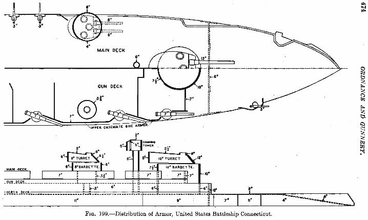
273 . .!rmor Protection of Ships.-The armor carried by ships of war is of various thicknesses, depending upon the size and purpose of the ship and on the position of the armor on or in the ship. The thickest armor is used to protect the water line and the vital parts of battleships. The present practice in the United States is to protect the whole length of the water line with a belt of armor 8 feet wide extending 4! feet above the water line and 3t feet below it.

ARMOR. 473
This belt, see Fig. 199, has its maximum thickness over that part of the ship that contains the machinery and the magazines. The thickness diminishes from the mid-ship section and is least at the bow and stern.
The gun turrets arc protected in front by the thickest armor. Armor of less thickness covers the casemates, barbettes, and sides of the turrets, the thickness depending upon the importance of the part protected and upon its exposure to hostile fire.e.
An armored deck of a thickness to prevent penetration by the fragments of exploded shell extends the whole length of the ship. This deck, the berth deck, Figs. 199 and 200, is flat over the
.' machinery and boiler spaces and slopes downward at the sides and at the bow and stern to . the bottom of the belt armor. On the heaviest ships the armored deck has a thicknetls of two inches over the flat part and four inches on the slopes, the thickness being reduced over the flat part in order to reduce the weight. The gun deck, next above the armored deck, is sometimes an . armored splinter deck one inch thick.
Across the main body of the ship, bow and stern, extends heavy athwartship armor, which, with the armored barbettes and turrets, provides protection to the body of the ship from fire from the front or rear. Thus with the side armor the. main body of the ship becomes an armored box, within which the crew, the machinery, the magazines, and the guns are protected.
With the improvements that have taken place in armor within the last fifteen years there has been a gradual reduction in the
. thickness of armor carried by ships of the various classes. The battleship Oregon, built in 1893, has a water line belt 18
inches in thickness, while the battleship Connecticut, commis. sioned in September, 1906, has but 11 inches of armor at her water
line. The arrangement of the annor on the battleship Connecticut
is shown in Figs. 199 and 200. Definitions.-The following definitions will assist toward a
ready understanding of the figures. TURRET.-A revolving armored structure in which one or two
guns are mounted. The guns revolve with the turret and are completely enclosed with the exception of the chase of the gun,
MAIN- .DECK.
6"
4'
8" ::::::::!:~
::ii:::=:J
MAIN DECK
GUN DECK
3f
® 7"
7
2'
---=;;=0::
Ij I, i! l " Il .. II
12° II
--i~--·-·--"-·-·---·--------·-·-------!:'-6" 01
" " ,-" f) ,I r: II I: " " ---.I~
4' if
~~ ... --.. , FIG. 199.-Distribution of Armor, United States Battleship Connecticut.
II>-;j!
~
~ ~
~ ~
~ ~
~ ~ ~ ~

> I l .
ARMOR. 475
which projects through a port hole in the front plate of the turret.
BARBETTE.-A fixed circular structure, armored, which protects the mechanism for the ammunition supply of the gun mounted above it and the mechanism of the turret containing the gun.
CASEMATE.-An isolated gun position for a broadside gun with fixed armor protection. The casemate completely encloses the gun with the exception of the chase, which projects through a port hole.
CENTRAL CITADEL.-Armor enclosing a series of broadside guns. There mayor may not be splinter bulkheads between the guns. With the bulkheads completely enclosing the guns the casemates.
'Ille Il00''.
FIG. 200.
citadel becomes a series of
274. Chilled Cast Iron Armor.-This armor on account of its thickness and great weight is used only on land. It is manufactured by Gruson of Germany. It is cast in large blocks whose outer faces are made very hard by chilling. The blocks are then built into turrets, usually of rounded shape.
On account of the great weight and hardness of the metal and the rounded shape of the turrets, this armor affords better protection than any other armor.
Gun Shields.-Guns of 6 inches caliber and less mounted in barbette in seacoast fortifications are provided with shields permanently attached to their carriages. The shields are made of Krupp plate 4t inches thick. The requirements of the ballistic test for these shields are as follows.
The shield, firmly supported by a backing of oak timbers, is subjected to three shots from a 5-inch gun. The striking velocity of the shot is 1500 feet and the impact normal. On the first im-

476 ORDNANCE AND GUNNERY.
pact, near the center of the shield, no portion of the projectile shall get through the shield, nor shall any through crack develop to an edge of the shield. The other two impacts are so located that no point of impact shall be less than three calibers of the projcci ilc . from another point of impact or from an edge of the shield. At the second and third impacts no projectile or fragment of projceiile shall go entirely through the shield.
The supports that hold the shield to the carriage are very heavy ribbo:q-shaped springs, which reduce the stress on the carriage frem the impact on the shield. The springs are of great strength in order to withstand the shock of impact. They are made of steel with a tensile strength of 110,000 Ibs., elastic limit .75,000 lbs., e ongation at rupture 15 per cent, contraction of area 25 per cent.
The fastening bolts must have a tensile strength of 80,000 lbs., and an elongation at rupture of 27 per cent.
The shields are curved around the front of the carriage and are inclined upward and to the rear at an angle of 40 degrees. The chase of the gun protrudes through a hole in the shield and other holes are provided for sighting purposes.
Fig. 201 shows the arrangement of the shield on a 6-inch barbette carriage.
Shields will probably be provided for all oarbette carriages. It is still a matter of discussion as to whether advantage is
derived by the use of gun shields, for while they serve to keep out the smaller projectiles they also serve to determine the bursting of larger projectiles whose destructive power may be sufficient to disable the gun and wholly destroy the gun detachment. Without the shields these projectiles would in many instances pass by, doing little or no harm.
Field Gun Shields.-Shields of hardened steel plate twotenths of an inch thick are attached to the gun carriage and caisson for the 3-inch field gun. These shields are tested by firings, at a range of 100 yards, with the 30 caliber rifle, using steel jacketed bullets with 2300 feet muzzle velocity. The plate must not be perforated, cracked, broken, or materially deformed .
. The front of the caisson chest is made of the same material as the shields and has the same thickness. The door of the chest, which opens upward to an angle of 30 degrees, is made of hardened steel plate 1\1\ of an inch t.hiclc


Page 476b Back of Fig. 201 Faces Page 477

CHAPTER XII.
PRIMERS AND FUSES FOR CANNON.
275. Classmcation.-Primers are the means employed to ignite the powder charges in guns.
They may be divided, according to the method by which ignition is produced, into three classes:
Friction primers, Electric primers, P ercussion primers.
Combination primers are those so constructed that they may be fired by any two of the above methods. Primers that close the vent . against the escape of the powder gases are called obturating primers.
All primers should be simple in construction, safe in handling, certain in action and not liable to deterioration in store. Electric primers in addition should be uniform as to the electric current required for firing.
Common Friction Primer.-The primer known as the common friction primer, formerly used in all cannon, is shown in Fig. 202.
The body b and the branch dare copper tubes. The tube b is filled with riBe powder, and is closed at its lower end by a wax stopper. a. The tube d is filled with the friction composition, whose ingredients are chlorate of potash, sulphide of antimony, ground glass, and sulphur mixed with a solution of gum arabic. Imbedded in the fliction composition is the serrated end of the copper wire c, the other end of the wire being formed into a loop for attachment of the hook of the lanyard. The outer end of the tube d is closed over the Battened end of the wire, which is bent over into a hook, as shown, and serves to hold the wire securely in
477

478 ORDNANCE AND GUNNERY.
place except when a stout pull is given to the lanyard. The pull on the lanyard straightens out the hook and draws the serrated wire through the friction composition, igniting it. The fire is communicated to the rifle powder in the tube b, and thence through the vent to the powder charge in the gun.
For use in axial vents, in order to prevent the primer being blown to the rear among the men of the gun detachment, a coiled copper wire e is added to the primer, one end of the wire being
I I 1 1
. 1 I
a FIG. 202.
made fast to the top of the prirrier body, the other end to the loop for lanyard hook. The coil is extended by the pull of the lanyard, and the primer when blown to the rear remains attached to the . lanyard.
Service Primers.-The primer above described is blown out of the gun by the explosion of the powder charge, leaving the vent open for the escape of gas. This disadvantage is overcome in modem practice by the use of obturating primers. The breech mechanisms of all guns now made are adapted to obturating primers, and the primer just described is no longer used in service . cannon.
The firing mechanism described in the chapter on guns, page 263, is fitted to most of the cannon in our service that do not use fixed ammunition. The firing mechanism is adapted to receive the primer and hold it firmly, and is provided with means [or firing the primer either by the pull of a lanyard or by electricity.
276. The Service Combination Primer.-The principal primer used in our service is a combination primer which is arranged tc

PRIMERS AND FUSE FOR CANNON. 479
be fired either by friction or by electricity. The primer is shown complete in Fig. 203. The igniting elements are shown on a larger
I I a
FIG. 203.
i
scale in Fig. 204. The igniting elements are assembled in the brass case I, which is screwed to its seat in the primer.
FRICTION ELEMENTs.-For firing by friction there is pressed into the case I an annular pellet of friction composition, shown in black in Fig. 204, which rests on a vul-
canite washer, g. The washer supports the IT~'-~"'~' ~ .. il~i~;p composition and prevents it from crum-bling when the pull which fires the primer is applied. The inner end of the firing wire, k, is loosely surrounded by the serrated cylinder h, which is imbedded up to the serrations in the friction composition. The
I
f FIG. 204.
headed inner end of the firing wire fits in a seat inside the serrated cylinder, and the parts are held securely in place by the forked metal support e and the closing nut b.
When the firing wire is pulled the serrated cylinder is drawn through the composition and ignites it. The conical end of the cylinder h is drawn to its seat in the rear part of the primer and prevents escape of gas to the rear. The flame from the friction composition passes through vents in the closing nut, b, and ignites the priming charge of compressed and loose black powder in the body of the primer.
The mouth of the primer is stopped by the brass cup, a, shellacked in place. This cup is blown out by the explosion of the primer charge, and the flames from the primer pass through the vent in the breech block and ignite the powder charge in the gun. The pellet of powder near the mouth of the primer is also blown through the vent and insures the ignition of the charge in the gun.

480 ORDNANCE AND GUNNERY.
ELECTRIC ELEMENTs.-For electric firing the wire k is covered with an insulating paper cylinder j and enters the primer body through a vulcanite plug i. The wire is in electric contact with the serrated cylinder h, Fig. 204, but this is insulated from the primer body by the vulcanite washer g and th~ pellet of friction composition, a non-conductor of electricity.
The electrical elements of the primer are assembled in the metal case j. The head of the forked metal support e is in contact with the headed end of the wire k, but not fastened to it. The forked end of the support is held in the vulcanite cup c. The brass contact nut b, screwed into the end of the case I, presses the assembled parts into intimate electrical contact. A platinum wire d is soldered to the head of the support e and to the contact nut b. An igniting charge of guncotton surrounds the wire.
When the primer is inserted in the gun the uninsulated button at the end of the wire j is grasped by the parts of an electric contact piece through which the electric firing current passes. The current passes through the wire j, the platinum bridge, and the body of the primer to the walls of the gun and thence to the ground.
The passage of the electric current heats the platinum wire, igniting the guncotton and the priming charge of powder.
It will be observed that the friction elements of the combination primer are independent of the electrical elements, and that when one of these primers fails to fire by electricity it may still be fired by friction.
If, however, the primer fails in an attempt to fire it by friction, it will not generally be possible to fire it electrically since the cylinder h, which has been pulled into the head of the primer, is out of contact with the part e and the platinum wire bridge. The current will then pass directly from h through the primer body and gun to the ground.
The primer should in this case be at once removed from the vent and not be again used.
The cuter button and wire k may be turned without danger of breaking the platinum wire bridge d.
When an electric or friction primer fails to fire it should be removed frpm the vent and the wire bent down and around the primer to prevent attempts to use it again.

PRIMERS AND FUSES FOR CANNON. 481
The metal parts of the primer are tinned to prevent corrosion. Other Friction and Electric Primers.-Primers arranged for
firing by friction alone are shown in Figs. 205 and 206. The primer
FIG. 205.
shown in Fig. 206, of simple and cheap construction. is for drill purposes only.
FIG. 2::>6.
The friction primer shown in Fig. 207 and the electric primer
FIG. 207.
shown in Fig. 208 are for use in the 3.6-inch and 7-inch mortars,
FIG. 208.
these guns not being provided with firing mechanisms. The primers are screwed into the vents in the breech blocks.
277. Percussion Primers.-The friction and electric primers described are used in' guns in which the projectiles and powder charges are loaded separately, the primer being separately inserted in the breech block. Percussion primers, and the electric primer describe(l with them, are, on the other hand, inserted in cartridge cases, in which are usually assembled both the projectile and the powder charge.
482 ORDNANCE AND GUNNERY.
The essential parts of a simple percussion primer such as the cap in a small arm cartridge, are the primer cup, the anvil, and the percussion composition.
Formerly the percussion composition of all service primers contained a large percentage of fulminate of mercury. On account of the danger involved in handling mixtures containing the fulminate of mercury, its use as a primer ingredient in service primers manufactured at the Frankford Arsenal has been abandoned, and a mixture known as the H-48 composition is now employed.
This mixture contains the same ingredients as the friction composition, but in different proportions, as follows:
Chlorate of potash, 49.6. Sulphide of antimony, 25.1.
Ground glass, J6.6. Sulphur, 8.7.
To insure the practically instantaneous ignition of smokeless powder charges, the addition of a small charge of quick-burning black powder is required. This may be inserted in the base of the smokeless powder charge, or may be contained in the primer. It is desirable, on account of the smoke produced by black powder and the fouling of the bore, that the quantity of black powder used be limited to the smallest amount that will produce prompt ~ndcomplete ignition of the smokeless powder. The minimum amounts required for different charges have been determined and, for fixed ammunition, are contained in the percussion and igniting primers. These primers are inserted in the head of the cartridge case, in the position occupied by the primer in the small arm cartridge.
Two sizes of percussion primers, the nO-grain and the 20-grain, have been adopted for all guns from the I-pounder to the 6-inch Armstrong inclusive.
nO-GRAIN PERCUSSION PRIMER.-The body f is of brass, 2.93 inches long, Fig. 209. A pocket is formed in the head of the case for the reception of the metal cup e containing the percussion com- ' position d. Projecting up from the bottom of the pocket is the anvil c against which the percussion composition is fired. Two vents are drilled through the bottom of the pocket. The priming charge consists of 110 grains of black powder inserted under high

PRIMERS AND FUSES FOR CANNON. 483
pressure into the primer body around a central wire. The withdrawal of the wire after the compression of the powder leaves a longitudinal hole the full length of the primer. Six sets of radial holes are drilled through the walls of the primer and through the compressed powder. The compression of the powder increases the time of burning of the priming charge and causes the primer to burn with a torch-like rather than an explosive effect, making the
FIG. 209.
igrution of the smokeless powder charge more complete. The holes through the priming charge increase the surface of combustion and the mass of flame, and direct the flames to different parts of the charge of powder, thus facilitating its complete ignition. The paper wad, a, shellacked in the mouth of the primer and the tin-foil covering, b, serve to keep out moisture and to protect the primer from the impact of the powder grains when transported assembled in cartridge cases.
This primer is used in cartridge cases for guns from the 6-pounder to the 6-inch Armstrong gun, inclusive.
20-GRAIN PERCUSSION PRlMER.-The 20-grain percui3Sion primer, shown in Fig. 210, length 1.1 inches, is used in cartridge cases for I-pounder subcaliber tubes, I-pounder machine guns, and 1.65-inch Hotchkiss guns.
[[px () FIG. 210.
2o-grain Saluting Primer.-This. primer, Fig. 211, costing less to manufacture than the 11O-grain primer, is to be used in place
FIG. 211
of the latter with blank charges only. The primer contains a charge of 20 grains of loose rifle powder. As black powder only is used in blank charges, a smaller igniting charge answers.

484 ORDNANCE AND GUNNERY.
no-grain Electric Primer.-This primer, Fig. 212, is similar in form to the nO-grain percussion primer just described, and has
FIG. 212.
the same priming charge similarly arranged. Ignition is produced electrically through the brass cup g, to which one end of the platinum wire e is soldered. A small quantity of guncotton surrounds the wire. Electric contact is made with the cup g by the insulated firing pin of the gun. The cup is insulated from the body of the primer by the cylinder f and bushing d, both of vulcanite. The brass
contact bushing c, to which the other end of the platinum wire is soldered, completes the electrical connection.
278. Combination Electric and Percussion Primer.-In Fig. 213 is shown a combination electric and percussion primer used in rapid-fire guns in the U. S. Navy. Its construction can be readily understood from the figure. The insulation is shown by the heavy black lines. When fired by percussion the percussion cap B not directly struck by the firing pin, FIG. 213.
but by the point of a plunger forced inward by the blow. Igniting Primers.-The igniting primm"!> are for use in car
tridge cases for subcaliber tubes for seacoast cannon not provided with percussion firing mechanism. They contain no means of ignition within themselves, but require for their ignition an auxiliary friction or electric primer which is inserted in the vent of the piece in the same manner as for service firing. The flame passes from the service primer through the vent in the breech block to the igniting primer in the head of the cartridge case. The flame from the service primer would not be sufficient to ignite properly the smokeless powder charge in the cartridge case, and therefore the igniting primer is added.
The nO-grain and the 20-grain igniting primers, Figs. 214 and 215, differ from the corresponding percussion primers in the substitution of the obturating cup a and obturating valve b, both of brass, for the percussion cup and anvil. The obturating cup a is
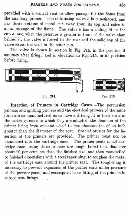
PRIMERS AND FUSES FOR CANNON. 485
provided with a central vent to allow passage for the flame from the auxiliary primer. The obturating valve b is cup-shaped, and has three sections of metal cut away from its top and sides to allow passage of the flame. The valve b has a sliding fit in the cup a, and when the pressure is greater in front of the valve than behind it, the valve is forced to the rear and the solid top of the valve closes the vent in the outer cup.
The valve is shown in section in Fig. 214, in the position' it assumes after firing; and in elevation in Fig. 215, in its position before firing.
FIG. 214. FiG. 215.
Insertion of Primers in Cartridge Cases.-The percussion primers and igniting primers and the electrical primers of the same form are so manufactured as to have a driving fit in their seats in the cartridge cases to which they are adapted, the diameter of the primer being from one-and-a-half to two thousandths of an inch greater than the diameter of the seat. Special presses for the insertion of the primers are provided. The primer must not be hammered into the cartridge case. The primer seats in all cartridge cases using these primers are rough bored to a diameter about 20 per cent less than the finished size, and then mandreiled to finished dimensions with a steel taper plug, to toughen the metal of the cartridge case around the primer seat. The toughening is necessary to prevent expansion of the primer seats under pressure of the powder gases, and consequent loose fitting of the primers in subsequent firings.
186 ORDNANCE AND GUNNERY.
FUSES.
279. Classification.-Fuses are the means employed to ignite the bursting charges of projectiles at any point in the flight of the projectile, or on impact.
They are of three general classes: Time fuses, Percussion fuses, Combination time and percussion fuses.
All fuses should be simple in construct~on, safe in handling, certain in action, and not liable to deterioration in store. In addition the rate of burning of the time train of the fuse must be uniform.
The time fuse alone, that is, without percussion element, is no longer used in modem ordnance.
Percussion Fuses.-A percussion fuse is one that is prepared for action by the shock of discharge, and that is caused to act by the shock of impact.
When ready to act, as after the shock of discharge, the fuse is said to be · armed.
Percussion fuses are inserted at the point or in the base of the projectile. In the projectiles for 1- and 2-pounder guns the fuse is inserted at the point. The percussion fuses for field, siege, and seacoast projectiles are base insertion fuses.
The percussion fuse consists essentially of the case or body, of brass, which contains and protects the inner parts and affords a means of fixing the fuse in the projectile; the plunger, carrying the firing pin and provided with devices to render the fuse safe in handling; the percussion composition, which is fired by the action of the plunger on impact; and the priming charge of black gunpowder.
The percussion composition of all service fuses manufactured at Frankford Arsenal is the same. The ingredients are chlorate of potash, sulphide of antimony, sulphur, ground glass, and shellac. The thoroughly pulverized ingredients are mixed dry, and alcohol is added to dissolve the shellac. The percussion pellets are formed by pressing the mixture while in a plastic state into the percussion-

PRIMERS AND FUSES FOR CANNON. 487
primer recess. Upon the evaporation of the alcohol the shellac causes the pellet to adhere to the metal of the recess.
A fulminate of mercury percussion composition was formerly used in fuse primers, but on account of the danger incident to handling this compound it has been abandoned as a primer ingredient.
It is still used abroad, and the percussion composition of both the Ehrhardt and Krupp combination time and percussion fuses contains fulminate of mercury.
Point Percussion Fuse.-Point percussion fuses are adapted to the projectiles for I-pounder and 2-pounder guns only.
FIG. 216. FIG. 217.
The body, a Fig. 216, is of brass. The percussion composition and the priming charge of black powder are assembled in a vented case, e, which is screwed into a recess formed in the head of the fuse. A thin brass disk, the primer shield, protects the percussion composition from the firing pin in the body of the fuse. It prevents any dislodgment of the composition during transportation or by shock of discharge and also restrains the firing pin during the flight of the projectile.
Contained in the body of the fuse is the plunger, which consists of the firing pin j, the cylindrical sleeve h, and the split-ring spring k, all of brass. The firing pin has an enlarged rear part joined to the forward part by a conical slope and provided near the bottom with a groove, l, of diameter slightly larger than the diameter of the forward part of the pin. A radial hole, i, through the pin near
488 ORDNANCE AND GUNNERY.
its forward end, and an axial hole from this point to the rear end of the pin, provide a passage for the flame from the priming charge. The rear part of the bore through the sleeve h is of diameter just sufficient to admit the spilt ring which rests against the forward shoulder of the counterbored recess in the sleeve and holds the firing pin so that its point is wholly within the sleeve. The front part of the sleeve is counterbored to permit ready entrance of the flame from the priming charge into the passage through the firing pin. The plunger thus assembled is placed in the fuse body, which is closed by the brass closing screw rn provided with a central vent which is in turn closed by the brass disk n. To prevent pressure of the closing screw on the plunger, which might cause expansion of the split ring and the arming of the fuse, the plunger is allowed a longitudinal play in the fuse body of from one to two hundredths of an inch. With the parts of the fuse in this position the point of the firing pin is prevented from coming Into contact with the percussion composition, and therefore the fuse cannot be fired.
If sufficient force is applied rearwardly to the sleeve h, the split ring k will be forced over the enlarged portion of the firing pin until it rests in the groove l near the bottom; and the sleeve, moving to the rear, will expose the point of the firing pin. The fuse is then armed, as shown in Fig. 217.
To insure arming of the fuse when fired the resistance of the split ring to expansion is made less than the force necessary to give the sleeve the maximum acceleration of the projectile. Therefore when the piece is fired and while the projectile is attaining its maximum acceleration, the pressure of the sleeve will force the ring over the enlarged part of the firing pin into the groove at the rear.
The diameter of this groove being greater than the diameter of the front part of the firing pin, the ring is now expanded into the counterbored recess in the sleeve and locks the sleeve and firing pin together, with the point of the firing pin projecting beyond the sleeve.
As the plunger of the fuse does not encounter the atmospheric resistance which retards the projectile in its flight, it is probable that during the flight of the projectile the plunger moves slowly

PRIMERS AND FUSES FOR CANNON. 489
forward until the point of the firing pin rests against the brass primer shield.
At impact of the projectile the combined weight of the plunger parts acts to force the point of the firing pin through the primer shield and into the percussion composition, igniting the composition.
The flame from the priming charge passes through the forward vents, through the passages in the plunger, and through the vent in the closing screw, blowing out the closing disk and igniting the bursting charge in the shell.
280. Base Percussion Fuse, for minor caliber shell. This fuse, as well as the point percussion fuse, is adapted to the projectiles for I-pounder and 2-pounder guns. The fuse for the projectiles of the 6-pounder gun and of the 2.38-inch field gun is similar in construction.
The fuse, Fig. 218, is similar in construction and action to the point percussion fuse. As the primed end of the fuse is toward the interior of the shell the flame from the priming charge passes directly to the bursting charge in the shell without passing through the body of the fuse. The flame passages through the plunger parts are therefore omitted. The primer cup b, containing the percussion composition and priming charge, is closed at its outer end by the brass disk a, which is secured in place by crimping over it a thin waH left on the brass closing cap screw c.
The act of arming a ring-resistance percus- FIG. 218.
sion fuse shortens the plunger and increases materially its longitudinal play in the fuse body. This fact permits a ready and simple means of inspecting for premature arming without dismantling the fuse. If the fuse be held close to the ear and shaken, the marked difference between the play of the plunger in an armed fuse and in an unarmed one can be readily discerned.
Centrifugal Fuses.-The centrifugal fuse of service pattern is the result of a long series of experiments made for the purpose of developing a fuse that would fulfill the requirements of absolute safety in handling and transportation, and certainty of action.

490 ORDNANCE AND GUNNERY.
In the case of ring-'-resistance fuses, or any fuse the action of which depends on the longitudinal stresses developed by the pressure in the gun, the conditions of safety in handling and certainty of action are opposing ones.
It was impossible to meet successfully both sets of conditions in all cases, the stress developed in the direction of the axis by accidental dropping of a fuse being in many cases higher than that developed in the gun. .
A fuse which is armed by the centrifugal force developed by the rotation of the projectile, and which is safe until the maximum velocity of rotation is nearly attained, has been developed at the Frankford Arsenal and is now used in the projectiles for low velocity guns; the mountain gun, and all howitzers and mortars. In these guns the maximum acceleration of the projectile in the bore is so low that the ring-resistance fuse must be very sensitive in order to insure arming, with the result that it becomes too sensitive for safety in handling and transportation. For the projectiles of other guns the fuses are similar, but are provided with ringresistance plungers instead of centrifugal plungers.
The centrifugal fuse, before arming, is shown in Fig. 219. Fig. 220 is a view of the plunger after arming.
The fuse body, or stock, and the primer parts of the centrifugal fuse do not differ materially from the corresponding parts of the ring-resistance fuses. To better protect the priming charge the closing cap screw b is lengthened and the vented primer-closing screw a is added.
The body of the centrifugal plunger is in two parts, nearly semicylindrical in shape, which when the fuse is at rest are held together by the pressure of a spiral spring g contained .in the cylindrical bushing e which is secured to one of the plunger halves. The spring exerts its pressure on the other half of the plunger through the bolt f. Pivoted in a recess in one half of the plunger is the firing pin d, which when the fuse is at rest is held with its point below the front surface of the plunger by the lever action of the link c which is pivoted in the other half. Under the action of the centrifugal force developed by the rapid rotation of the projectile the two halves of the plunger separate. The separating movement causes the rotation 'of the . firing pin d, the point of which is

PRIMERS AND FUSES FOR CANNON. 491
now held in advance of the front surface of the plunger, Fig. 220, ready, on impact of the projectile, to pierce the brass primer shield and ignite the percussion composition. When the fuse is armed the end of the link c rests on the pivot of the firing pin, thus affording support to the firing pin when it strikes the percussion primer. The separation of the plunger parts is limited by the nut i coming to a bearing on a shoulder in the bushing e, so
FIG. 219. FIG. 220. FIG. 22l.
as not to permit the diameter of the expanded plunger to equal the interior diameter of fuse stock, see Fig. 222.
A rotating piece, h Figs. 219 and 221, screwed into head of fuse stock, engages in a corresponding slot cut through the bottom of both plunger-halves and insures rotation of the plunger with the shell.
The strength of the spring g is so adjusted that the fuse will not arm until its rapidity of revolution is a certain percentage of that expected in the shell in which it is to be used, and that it will certainly arm when the rapidity of revolution approximates that expected in the shell. Should the parts of the plunger be accidentally separated and the fuse armed by a sudden jolt or jar in transportation or handling, the reaction of the spring will immediately bring the plunger to the unarmed condition.
The fuse just described is called the F fuse.
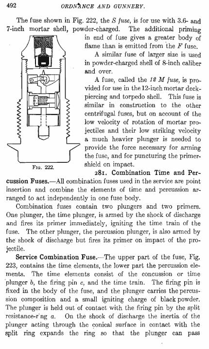
492 ORDN'ANCE AND GUNNERY.
The fuse shown in Fig. 222, the S luse, is for use with 3.6- and 7-inch mortar shell, powder-charged. The additional priming
FIG. 222.
in end of fuse gives a greater body of flame than is emitted from 'the F fuse.
A similar fuse of larger size is used in powder-charged shell of 8-inch caliber and over.
A fuse, called the 12 M luse, is provided for use in the 12-inch mortar deckpiercing and torpedo shell. This fuse is similar in construction to the other centrifugal fuses, but on account of the low velocity of rotation of mortar projectiles and their low striking velocity a much heavier plunger is needed to provide the force necessary for arming the fuse, and for puncturing the primershield on impact.
281. Combination Time and Per-cussion Fuses.-All combination fuses used in the service are point insertion and combine the elements of time and percussion arranged to act independently in one fuse body.
Combination fuses contain two plungers and two primers. One plunger, the time plunger, is armed by the shock of discharge and fires its primer immediately, igniting the time train of the fuse. The other plunger, the percussion plunger, is also armed by the shock of discharge but fires its primer on impact of the projectile.
Service Combination Fuse.-The upper part of the fuse, Fig. 223, contains the time. elements, the lower part the percussion elements. The time elements consist of the concussion or time 'plunger b, the firing pin c, and the time train. The firing pin is fixed in the body of the fuse, and the plunger carries the percussion composition and a small igniting charge of black powder. The plunger is held out of contact with the firing pin by the split resistance-r'ng a. On the shock of discharge the inertia of the plunger acting through the conical surface in contact with the split ring expands the ring so that the plunger can pass

PRIMERS AND FUSES FOR CANNON 493
through it ahd carry the percussion composition to the firing pin.
The time train of the fuse is composed of two rings of powder, f and h, contained in grooves cut in the two time-train rings m and n. The grooves are not cut completely around the rings, but a solid portion is left between the ends of the groove in each ring.
FIG. 223.
Mealed powder is compressed into the grooves under a pressure of 70,000 pounds per square inch, forming a train 7 inches long, the combined length of the two grooves.
The flame from the percussion composition passes through the vent d, igniting the compressed tubular powder pellet e, which in turn ignites one end of the upper time train f. When the fuse is set at zero the flame passes immediately from the upper time train through the powder pellet g to one end of the lower time train h; thence through the pellet i and vent i to the powder k in the annular magazine at the base of the fuse.
Under each of the time rings is a felt washer, 0 and p, that closes the jo~nt under the ring against the passage of flame, except through the hole in the washer directly over the vent in the part below. The upper washer 0 is glued to the upper corrugated surface of the lower time ring n and moves with that ring. The lower washer p is glued to the fuse body and is stationary. The upper

494 ORDNANCE AND GUNNERY.
time ring m is fixed in position by two pins l halved into the fuse body and the ring. The lower time ring is movable, and any of the graduations on its exterior, see Fig. 224, which correspond to
FIG. 224.
seconds and fifths of seconds of burning, may be brought to the datum line marked on body of fuse below the ring. The ring is moved, in setting, by means of a wrench applied to the projecting stud w.
To set the fuse for any time of burning, say 20 seconds, move the lower time ring n until the mark 20 is over the datum line. On ignition of the primer the flame ignites the upper time train I, which burns clockwise, looking from base to point of fuse, until the hole through the washer over the zero mark of the lower ring n is encountered. The flame then passes through the vent g to the lower time train n, which burns anti-clockwise until the mark 20 is reached. This mark being over the vent i in the body of fuse, the flame now passes to the magazine k. The setting of the fuse consists in fixing the position of the passage from the upper to the. lower time train, so as to include a greater or less length of each train between the vent e and the vent i.
In each time ring a vent opens from the initial end of the powder train to the exterior. The vent contains a pellet of powder and is covered by a thin brass cup. The vent in the lower

PRIMERS AND FUSES FOR CANNON . 495
. time ring is seen at x in Fig. 223. The caps, x, of both vents are shown in Fig. 224. The blowing out of the cap affords a passage to the open air for the flame from the burning time train, thus preventing the bursting of the fuse by the pressure of the contained gases.
When the fuse is set at safety, indicated by the letter S stamped on the lower time ring, the position shown in Fig. 224, the solid metal between the ends of the upper time train is over the vent g to the lower train, and the solid metal between the ends of the lower train is over the vent i leading to the magazine. In case of accidental firing by the time plunger, the upper train will be completely consumed without communicating fire to the lower train and to the magazine. The fuse is habitually carried at t.his setting, which serves also when it is desired to explode the shell by impact only.
For percussion firing the fuse is now provided with a ringresistance plunger similar to that shown in Fig. 218. Better results are obtained with the ring-resistance plunger than with the centrifugal plunger, which was formerly used in these fuses and is shown at r in Fig. 223. A vent s leads from the percussion primer to the annular magazine k. A thin brass cap t separates the lower plunger-recess from the powder in the four radial chambers v cut in the bottom closing screw. The central vent in the closing screw is closed by a piece of shellacked linen, held in place by a brass washer.
These fuses are issued fixed in the loaded projectiles. For protection in transportation the fuse is covered by a spun brass cap, soldered on to the head of the projectile. The soldering strip is torn off and the cover removed before using the projectile.
A 21-second fuse of this pattern is now in service, and a 31-second fuse is being developed.
282. COMBINATION FUSE, OLD PATTERN.-As the former model of combination fuse may perhaps still be encountered in service, it is illustrated here. The time train, b Fig. 225, is made by filling a lead tube with mealed powder and then drawing the filled tube through dies until its diameter has been reduced to the desired dimension. The powder train is thereby given practically uniform density, so that it burns more uniformly than the time

496 ORDNANCE AND GUNNERY.
trains of previous fuses. The results, however, were not so good as the results obtained with fuses of the present service model.
The time train, b, incased in the lead tube, is wound spirally around the lead cone c. To set the fuse for any time of burning the time train and lead cone are punctured,by means of a tool provided for the purpose, at the point on the scale marked on the cover of fuse corresponding to the time of burning desired. The puncture passes completely through the time train and the lead cone behind it, forming a channel from the annular space in which
FIG. 225.
the letter b appears to the powder in the time train. When the projectile is fired the flame from the percussion composition ignites the compressed powder ring d, and the flame from this ring ignites the time train at the point at which it has been punctured. The safety pin a retains the time plunger in its unarmed position, and must be withdrawn before placing the projectile in the gun.
Two fuses of this pattern were made, one with a I5-second time train and the other with a 28-second time train.

PRIMERS AND FUSES FOR CANNON. 497
EHRHARDT COMBINATION FusE.-This fuse is similar in construction to the Frankford Arsenal fuse, latest pattern, described above and differs only in details.
The arming of the time plunger of the Ehrhardt fuse, Fig. 226, is resisted by the U-shaped spring a, the upper ends of which are sprung out into a counterbored recess in the closing cap, and by
FIG. 226.
the slender brass pin b, which passes through the plunger and both sides of the closing cap. At discharge of the piece the inertia of the plunger shears the pin b and straightens the U-shaped spring a, permitting the plunger to strike the firing pin.
In the percussion mechanism the composition is carried in the . plunger and the firing pin is fixed in the diaphragm d in body of fuse. The plunger is held away from the firing pin, before firing, by the brass restraining pin c. The pin is let into a hole in the diaphragm d, the head of the pin abutting against a shoulder near the bottom of the hole. The restraining pellet of powder e is · pressed in to fill the recess above the pin. A perforated brass
. disk and a piece of linen close the hole at its upper end anq iprevent the powder pellet from being jarred out of place. 71h.e P1lffi~

498 ORlJNANCE AND GUNNERY.
ing of this pellet on ignition from the time plunger leaves the restraining pin and percussion plunger free' to move forw-ard at impact.
A compressed charge of black powder, g, is inser~ed in~o the extension· of the closing screw f to reinforce the magazine charge and effectually to carry the flame to the base charge in the shrapnel.
The Krupp combination fuse does not differ essentially from the Ehrhardt fuse. The shear pin through time p:unger is omitted, the U-shaped spring being made strong enough to offer sufficient resistance against accidental arming. The percussion plunger, carrying the percussion composition, is held away from the firing pin, before firing, by a sleeve and an inverted U-shaped resistance spring. A spiral spring between plunger and firing pin prevents the creeping forward of the plunger during the flight of the projectile.
Detonating Fuses.-These fuses are for use in shell containing high explosives.
FIG. 227.
Fig. 227 shows the form of detonating fuse for point insertion in field shell. Fig. 228 shows the form of fuse for base insertion in siege and seacoast projectiles.
9:35 ----.---.--.----.--.--i'\
FIG. 228.
In order to prevent the unscrewing of the fuse during flight of the projectile, all point insertion fuses are provided with right-

PRIMERS AND FUSES FOR CANNON. 499
handed screw threads and base insertion fuses with left-handed threads.
283. The Fuse Setter.-The fuse setter is a device for the rapid and accurate setting of the time fuse in the field gun projectile. It is attached to a hinged bracket on the caisson for the field gun, see Fig. 122, in a position convenient for the cannoneer who serves the caisson.
The base of the fuse setter, Fig. 229, is fixed to the bracket 011
the caisson. Mounted on the base are two movable rings called the corrector ring and range ring. The range ring carries the range scale graduated in yards, and the corrector ring carries an index or pointer that moves between the corrector scales that are fastened to the fixed cover. The base and the two rings are bored out conically to fit over the combination time and percussion fuse used in the 3-inch projectile. The corrector ring is notched to receive the rotating stud, w Fig. 224, which projects from the time train ring of the fuse. A spring plunger projects inwardly from the range ring of the fuse setter.
A guide fixed to the base serves to direct the point of the projectile into the socket of the fuse setter and to support the cartridge during the operation of fuse setting.
To set the fuse for the time of burning corresponding to any range, as 1000 yards, the range ring is turned by means of the r3I1ge-worm handle until the 1000 mark on the range scale is opposite the datum line marked on the corrector scale, see Fig. 229. The weather-proof cover of the time fuse in the projectile is stripped off and the point of the projectile is then placed in the fuse setter, the rotating stud on the fuse engaging in the notch in
. the corrector ring. The cartridge is then turned slowly in a clock-wise direction until the spring plunger, which has been pushed in by the insertion of the fuse in the fuse setter, is forced out into a notch prepared for it in the body of the fuse. The plunger prevents .further rotation of the cartridge, the time fuse of which has now been set to the proper time of burning for 1000 yards.
The rate of burning of different fuses of the same lot will be uniform, but it may vary slightly from the rate of burning used in the graduation of the scale of the fuse setter. This must be determined by actual firings, and if after a few shots it is found that

500' ORDNANCE AND GUNl'I-ERY.
the projectiles burst short of or beyond the range for which the time fuse is set, or if the height of burst is not exactly as desired,
/r--------------- ---17__._1'0.- IntUat: ,
,," ,~ --;..---- --- - ---- ~rectDr- ,S"cal«s ( , , , , ,
---cOrl1!'Cl'or JoViJrm
------ -lIroh:h thr Rolalin(! Pi,. ."..-uz.
----~ -Plun!P'r
l "'-------"",
"''''''''- - - - - -t:OlIcr
-).fjJlW-_.-- ---- du.ifle
--- --- -- Rangt!l;S'ca(,
. - --- --Range Illng
-\\-----_. ___ .C1Jrr.'ctc~r RlnS'
- - - -- - - ilolating Pin lViI/cit.
- -- --Base
-----douer
----&'1 ampll'lg .BolrJ
FIG. 229.-Fuse Eetter for 3-inch Projectiles.
a correction is made in the setting of the fuse by means of the corrector ring in the fuse setter.
The height of burst may be increased or diminished by turnm6
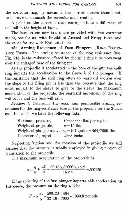
PRIMERS AND FUSES FOR CANNON. 501
the corrector ring, by means of the corrector-worm thumb nut, to increase or diminish the corrector scale reading.
A point on the corrector scale corresponds to a difference of one mil in the height of burst.
The fuse setters now issued are provided with two corrector scales, one for use with Frankford Arsenal and Krupp fuses, and the other for use with Ehrhardt fuses.
284. Arming Resistance of Fuse Plungers. . RING RESISTANCE FUSES.-The arming resistance of the ring resistance fuse, Fig. 216, is the resistance offered by the split ring k to movement over the enlarged base of the firing pin.
As the projectile is accelerated in the bore of the gun the split ring imparts the acceleration to the sleeve h of the plunger. If the resistance that the split ring offers to rearward motion over the slope of the firing pin . is less than the pressure that the ring must impart to the sleeve to give to the sleeve the maximum acceleration of the projectile, the rearward movement of the ring will occur and the fuse will arm.
Problem 1. Determine the maximum permissible arming resistance for the ring-resistance fuse in the projectile for the 3-inch gun, for which we have the following data.
Maximum pressure, P=33,000 lbs. per sq. in. Weight of projectile, W = 15 lbs. Weight of plunger sleeve, w.=464 grains =464/7000 Ibs. Diameter of projectile, d =3 inches.
Neglecting friction and the rotation of the projectile we will assume that the pressure is wholly employed in giving motion of translation to the projectile.
The maximum acceleration of the projectile is
a =Jl pnd2 = 32.16X33000XnX9 =500120 w 4 15X4
If the split ring of the fuse plunger imparts this acceleration to the sleeve, the pressure on the ring will be
u. 500120X464 . F =0'. g = 32.16 X 7000 = 1030.8 pounds

W2 ORDNANCE AND GUNNERY.
Therefore the plunger with sleeve weighing 464 grains will arm in the gun if the arming resistance of the fuse is anything less than 1030.8 pounds.
285. Problem 2. The actual arming resistance of the fuse for the 3-inch projectile is 220 pounds. What pressure per square inch is required in the gun in order to arm the fuse?
Equating the values of a in the equations established in the preceding problem, and writing p for P to indicate any pressure per square inch, we obtain
rcd2 1 F p--=-
4 w w.
The total pressure on the projectile at any instant divided by" the weight of the projectile is equal to the pressure on the sleeve at the instant divided by the weight bf the sleeve ..
Making F=220, and substituting for the other quantities the values as given in the preceding problem, we find
4X15X220X7000 . p rcX9X464. =7043 lbs. per sq. m.
The fuse will arm under any pressure in excess of this. Problem 3. What is the minimum effective powder pressure
that will arm the ring-resistance fuse described below, when fired from the 6-inch gl!n?
Weight of projectile, w=106Ibs. . Weight of plunger sleeve, Ws = 700 grains=O.11bs. Ring resistance to arming, = 220 lbs.
Ans. p =8248Ibs. per sq. in. 286. CENTRIFUGAL FusE.-The arming resistance of the cen
trifugal fuse, Fig. 219, is the pressure exerted by the spring g, which holds the plunger halves together. The centrifugal force due to the rotation of the projectile tends to separate the plunger halves. In order that the fuse may be armed when the projectile strikes, the arming resistance must be less than the centrifugal force deve~oped by the rotation in the projectile at impact. For simplicity we will consider that the projectile's velocity of rota~
tion at impact is the same as at the muzzle of the gun.

PRlMERS AND FUSES FOR CANNON. 508
Problem ,4.. Determine the maximum permissible arming resistance for the centrifugal fuse in the 12-inch mortar projectile, for which we have the following data.
Weight of plunger complete, 660 grains. Weight of plunger half, Ws = 330 grains = 330/7000 lbs. Radius of center of gravity of plunger half, r=OA ins. =OA/12ft. Twist at muzzle, n=25. Muzzle velocity of projectile, V = 950 f. s. Diameter of projectile, d = 12 inches = 1 ft.
Combining equations (62) and (61), page 250, we find for the velocity of rotation of the projectile at the muzzle
w=2Vn/dn=2 n 950/25=238.76
The centrifugal force acting on each plunger half is
F =mav2 / p =wsw2r2 /gp
in which v is the linear velocity of the center of gravity of the r
plunger half, due to the rotation, r the radius of the center of gravity, p the radius of its path.
At the beginning of movement p = r, and we have
330X238.762 X0.4 F=wsw2r/g= 7000X32.16X12 =2.79Ibs.
for the force tending to move each plunger half. If the resistance of the spring is less than 2.79 lbs. the fuse will
start to arm. As the plunger halves separate, the resistance of . the spring
increases in the manner shown by equation (14), page 285.
S=G'+Gx
It will be seen, from the value of F above, that F increases directly with r. In order that the fuse, after starting to arm, may arm completely, the values of G' and G must be such, that is, the spring must be of such construction, that S will not increase more rapidly than F.

504 ORDNANCE AND GUNNERY.
287. Problem 5. Assume that the spring in the plunger of the fuse for the 12-inch mortar projectile is under a tension of I! lbs. What muzzle velocity is required in the projectile to arm the fuse?
We have
from which
Solving for V
w=2V,,/dn
F=w.urr/g
w= (Fg/w.r)t =2V,,/dn
The force required for arming is in this case 1.5 pounds. Substituting 1.5for F, a.nd for the other quantities the values as given in the preceding problem, we have
V = 25(1.5X32.16X7000X12)! =697 14 f . ~" 330X0.4 .. s.
The fuse will arm for any muzzle velocity of the projectile exceeding 697.14 foot seconds.
Problem 6. What is the minimum muzzle velocity that will arm the centrifugal fuse described below, when fired from a 6-inch howitzer?
Weight of plunger half, w. = 400 grains = 4/70 lbs. Radius of center of gravity of plunger half, r=0.5 in. =0.5/12 fto Spring resistance to arming, F =2 lbs. Twist of rifling at muzzle, n=25. Diameter of projectile, d=6 in. =0.5 ft.
Ans. V =327 foot seconds,

CHAPTER XIII.
SIGHTS.
288. Purpose.-It has been shown in ext.erior ballistics that in order that the project.ile from any gun may hit the target the gun must be fired at a certain angle of elevation, depending upon the range and upon the relative level of the gun and target, and must be given such direction to the right or left of the target as to neutralize the deviation of the shot from the plane of fire due to the drift and wind.
The elevation in the plane of fire and the allowance for deviation from the vertical plane containing gun · and target are determined beforehand either by calculation or estimate. Direction is given to the axis of the gun by whatever means may be provided. The axis of the gun when given the determined elevation and deviation has a fixed relation to the line from the gun to the target.
The sights of the gun provide the means of determining when the axis of the gun has the predetermined direction with respect to the line from gun to target.
Principle and Methods.-The principle of sighting is simple. It consists in determining, by means of the sights, a line to which the axis of the gun has the fixed relation already determined as being required between the axis and the line to the target; and then, by looking through the sights, making the line of the sights and the line to the target coincide.
The line of sight on a gun may be fixed in one of two ways: first, by means of two plain or open sights, the rear one of which has a peep or notch capable of adjustment in vertical and horizontal dirl'ctions; second, by means of a telescope, whose axis or line of collimation may be given any direction desired.
505

506 ORDNANCE AND GUNNERY.
In Fig. 230 0 represents the peep of the rear sight in its zero position, the line from 0 to the front sight A being parallel to the axis of the piece. Or the line 0 A. may represent the line of collimation of a telescope, the telescope being pivoted at A. If now we calculate that to reach the target at F, under the conditions prevailing, a certain angle of elevation is required and a certain deviation to the left, we lift the peep of the rear sight to the point C so that OAC is the required angle of elevation, and then move the peep horizontally from C to E to obtain the required deviation. The line of sight is now the line EA, and if the gun is maneuvered so that this line is made to pass through the target, the axis has
B
/.P~.~/C~~,.~~A~~~I~~_§_-§--~--~-~~~::::::::===; (. ',';'-\ , --Jt~ ... -""'---, .... ' ... 0 .". ... ,.-,---
~--.. ---. . ,~-
FIG. 230 ..
then the elevation and deviation required under the existing conditions.
The gun is aimed at the target F, but its axis, parallel to the line CB, is practically pointed at B, which is above F by the vertical distance BD and to the left of F by the horizontal distance DF.
TARGET NOT IN VIEw.-In the foregoing the target has been assumed to be in view. If the target is not in view the required position of the axis of the gun with respect to a horizontal line in the vertical plane through gun and· target is determined. The vertical angle between this line and the axis is the angle of elevatiop.. This angle is laid off by the sights as before and the gun is elevated until . the line of sight AC is horizontal as determined by means of a spirit level mounted on the rear sight. Other means must be employed for detemlining the direction -in this case.
289. Graduation of Rear Sights.-The graduations of the rear sight for elevation may be, and often are, in degrees and minutes of arc, the center of the arc being at the center of motion

SIGHTS. 507
of the rear sight. But as the powder charges of guns are made up to give certain fixed muzzle velocities to the projectiles, the angle of elevation required to attain any range with the given muzzle velocity under standard atmospheric conditions may be determined in advance, and the rear sight be graduated for range instead of angular elevation.
The range graduation is the more convenient, for the range may usually be readily determined, and the graduation on the rear sight indicates at once the proper elevation.
The horizontal deflection scale, by means of which allowance is made for deviation to the right or left, is graduated, in sights for field artillery, to thousandths of the range. These graduations are called mils, from the French millwmes. It is apparent from Fig. 230 that if EC is n thousandths of AO, the horizontal distance DF will be n thousandths of AD and practically of the range AF. In sights for seacoast artillery the least division of the deflection scale is three minutes of are, which corresponds to a , deflection of 0.00087 of the range, approximately 1/1000.
Correction for Drift.-The deviation of the projectile due to drift, which is caused by the rotation of the projectile and the resistance of the air, may be determined for any range by the formulas of exterior ballistics, and thus the curve of drift may be constructed for any gun. If then the rear flight is so constructed that as the peep is lifted in elevation to any range it is automatically moved horizontally just enough to compensate for the drift at that range, the sight makes automatic correction for the drift, and need be further adjusted only for the wind or other atmospheric deviating influences.
In all service guns the drift of the projectile is to the right. The drift increases with the range. The .rear sigut with automatic drift correction therefore moves to the left as it i.,> r.aised in elevation. In our service, automatic drift correction wlH be found only in sights for small arms.
It is well to bear in mind that the projectile follows the movement of the rear sight, going higher as the sight is raised, and to the right or left as the sight is moved to the right or left.
290. Correction for Inclination of Site.-The angle of elevation of a gun is the angle, in a vertwal plane, that the axis of the

508 ORDNANCE AND GUNNERY.
gun makes with the horizontal. In Fig. 231 let r be the point to which the rear sight must be raised, in the vertical plane of the axis, to give to the gun a desired angle of elevation equal to otr, f representing the front sight. h is a horizontal line in the vertical plane of t.he axis. Now suppose the gun to be revolved to the left about its axis. The axis of the gun remains in the vertical plane, but the points r, 0, and f revolve to the left out of the plane; and as r is farther from the center than 0 and f, its movement is greater than the equal movements of 0 and f. We may therefore consider that, relatively to 0 and f, r takes some position r'. Pro-
FIG. 231.
jecting r' on the vertical plane, at rtf, we see that the angle of sight ofr' produces an angle of elevation o/r", which is less than the desired angle ofr. It is apparent too that the line of sight through r' will cause the gun to be pointed to the left of the plane of ofr.
If, however, the sight is pivoted at 0 so that it has movement in a plane perpendicular to the axis of the gun, we are enabled, when the gun has been revolved, to make the sight arm or' vertical; and since the points 0 and i have revolw.d together, or', now coincident with or, will subtend the desired vertical angle ofr.
It is therefore essential that the rear sights for guns that. are likely to be fired on uneven sit.es shall be so const.ruct.ed that the sight arm may revolve about. the zero point of the elevation scale in a plane perpendicular to the axis of the gun. We will find that the rear sights for all guns mounted on wheeled carriages are constructed in this manner.
Guns of position are mounted on carriages that rest on level platforms, and their sights arc so adjusted as to always move in a vertical plane.

SIGHTS. 509
Location of Sights.-8ights for all guns are now placed on some non-recoiling part of the gun carriage, and the elevating and traversing mechanisms are under the control of the cannoneer at the sights, so that the operation of sighting may go on continuously during the loading and firing of the piece.
LINE SIGHTS.-l\10st guns are provided with line sights fixed to the gun. They serve only to give general direction to the piece. and consist of a front stud with conical point, and a notched bar on the top of the breech. The line extending from a point over the center of the notch at the level of the top of the bar to the point of the front sight is parallel to the axis of the piece.
The most recent service sight.s and other appliances used in gun pointing will now be described. The sights mounted on the various guns of older model will readily be understood after a study of these.
291. Sights for Mobile Artillery.--The appliances provided for sighting the 3-inch field piece, and other pieces on wheeled carriages, include line sights, the adjustable or tangent sight, the panoramic sight and the range quadrant.
The line sights are fixed to the gun as already described.
The Adjustable or Tangent Sight.-The adjustable sight consists of a fixed front sight and an adjustable rear sight.
The front sight, supported in a bracket on the crarlle, is a short tube, Fig. 232, \vhose axis is marked hy the intersection of two cross wires set in the tube at angles of 45 degrees with the horizon. A bead on top of the tube serves for approximate determination of direction.
The rear sight, Fig. 233, is shown viewed from the left in the left-hand figure, and from the rear in the figure on the right. The rear sight bracket is seated FIG. 232.
in a socket attached to the cradle of the carriage, on the left side. At the upper end of the bracket two seats are formed for the attachment of the socket for the sight. The seats are faced in a plane perpendicular to the axis of the

510 ORDNANCE AND GUNNERY.
piece and circular guides are cut on them, with the zero index of the elevation scale as a center.
The shank socket which holds the rear sight is mounted on the bracket and has circular motion on the guides under the action of
1 Iq
i ~
~
~~r;~~~~~~~~1 the transverse leveling screw. This arrangement permits the correction for inclination of site by revolution of the rear site in a plane perpendicular to the axis of the gun until the sight is vertical, as indicated by the transven3e level fixed to the socket.
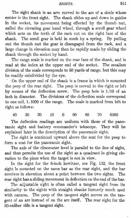
SIGHTS. 511
The sight shank is an arm curved to the arc of a circle whose center is the front sight. The shank slides up and down in guides in the socket, its movement being effected by the thumb nut, called the elevating gear hand wheel, through a scroll gear wheel which acts on the teeth of the rack cut on the right face of the shank. The scron gear is held in mesh by a spring. By pulling out the thumb nut the gear is disengaged from the rack, .and a large change in elevation may then be rapidly made by sliding the shank through the socket by hand.
The range scale is marked on the rear face of the shank, and is read at the index at the upper end of the socket. The smallest division of the scale corresponds to 50 yards of range. but this may be readily subdivided by the eye. , On the upper end of the shank is a frame in which is mounted
the peep of the rear sight. The peep is moved to the right or left by means of the deflection screw. The peep hole is 1/ 10 of an inch in diameter. The divisions of the deflection scale correspond to one mil, 1/1000 of the range. The scale is marked from left to right as follows:
40 30 20 10 o 90 80 70 6360
The deflection readings arc uniform with those of the pano. ramic sight and battery commander's telescope. They will be explained later in the description of the panoramic sight.
The sight is continued upward above the seat for the peep to fomi a seat for the panoramic sight.
The axis of thE' clinometer level is parallel to the line of sight, and thus.pemtits the use of the sight as a quadrant in giving elevation to the piece when the target is not in view.
In the sight for the 6-inch howitzer, see Fig. 132, the f~ont sight is mounted on the same bar as the rear sight, and the bar revolves in elevation about a point between the two sights. The rear sight has a sliding movement in deflection on the end of the bar.
The adjustable s:ght is often caned a tangent sight from its similarity to the sights with straight shanks fonnerly much w;ed with cannon. The peep of the tangent sight moves on the tangent of an arc instead of on the arc itself. The rear sight for the 30.ca.liber rifle is a tangent sight.

512 ORDNANCE AND GUNNERY.
For field howitzer.:; the seats for the front and rear sight" are alike, so that the positions of the sights may be reversed for indirect sighting, which consists in directing the line of sight at any ohject other than the target.
292. The Panoramic Sight.-The fire from modern field guns is so accurate and destructive that it has been found necessary in recent battles to establish field batteries always in positions out of view of the enemy, in order to protect the batteries from the fire of the enemy's guns.
Indirect sighting becomes then of necessity the usual method of sighting guns in battle.
The panoramic sight affords the means of aiming the gun by directing the line of sight on any object in view from the gun. At t.he same time it offers the advantages of a telescopic sight in direct or indirect aiming.
The panoramic sight is a telescope so fitted with reflectors and prisms that a magnified image of an object anywhere in view may be brought to the eye without change in the direction of sight.
The panoramic sight for the field and siege guns is shown in Fig. 234. The rays of light from the object viewed enter the sight through the plain glass window in the head piece and are bent downward by the prism of total reflection A, rectified vertically by the prism B, focussed by the object lens C, and rectified laterally by the gabled prism D, so that there is presented to the eyepiece E a rectified image of the object, which image is magnified by the two lenses of the eyrpiece.
The magnifying power of the instrument is 4 and th~ field of view is 10 degrees.
THE ROTATING PRIsM.-The interior tuhe containing the prism B and the objective C is mounted so that it may rotate in the body of the telescope.
The prism B is rectangular in cross section. Its upper and lower faces are oblique to its axis, and it..<; length is such that a ray that enters the prism axially emerges axially. Every ray entering parallel to the axis therefore emerges at an equal distance on the other side of the axis. A vertical ray entering the prism at a, Fig. 235, is reflected by the back of the prism and emerges at c. Now
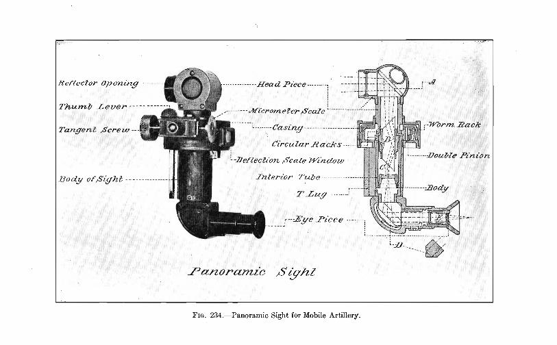
p;'-.' ,.,
Rerlecior Opening---- ----- ---- ----------Head Piece -- - ------~
Thumb Lever --- --- -- -- /- --- ----,jlfi'crOJne'ler Scale ~ -------- - - - -- -:--
Tangent ~crew -- ----- -- Casing ---------- -----------,
Circular Eades ---
c:ZJeflection .scale Window
Body of,Sight _ c __ ___ ___ _ __ _ _ ' Interior TuZ,e ........ -------
T Lug-------.. -:
,--:Eye .Piece .. ------; - - - -- -' .
Panoranuc,$ ight
FIG. 234.-Panoramic Sight for Mobile Artillery.

Page 212b Back of Fig. 234 Faces Page 213

SIGHTS. 513
if the prism is revolved through any angle, say 45 degrees, as represented in the figure by the posi tion shown in broken lines, the ray a will emerge at e, the back of the prism now being at the angle of 45 degrees with its original position; and the /', angle throug~ which the.ray has.mo;ed, meas~red ~V---" from the aXIS of the prIsm, wluch IS the aXIS of <" 'y'" rotation, is 90 degrees. The angular movement of ',e / . / the ray IS therefore double the angular movement ',,/ of the prism. Consequently the image of an object I a
seen through the prism rotates through twice the angle of rotation of the prism.
The head. piece containing the prism A is also mounted to rotate on the body of the telescope, and in order to counteract t.he doubled angular movement of the image by the prism B, the head piece is made to rotate twice as fast as the prism. The image of any object then rotates through the FIG. 235.
same angle as the head piece, and the relative positions of objects in the field of view are not changed.
The different movements of A and B are accomplished by means of one t.angent screw through gearing contained in the cylindrical casing seen at the junction of the rotating parts.
THE GRADlJA'l'ED SCALE.-The angular movement of the head piece is indicated by a graduat.ed scale on its perimeter, visible through a window in the rear of the casing. When the index on the casing is at the zero of the scale, the line of sight of the pano-· ramic sight is in the vertical plane parallel to the axis of the piece. If at the same time the tangent sight on which the panoramic sight is mounted is at the zero of the elevation scale, the line of sight of the panoramic sight is parallel to the axis of the piece.
In the scale on the head piece the circle is divided in 64 equal parts, numbered clockwise. One complete turn of the tangent screw moves the head ' piece through one of these angles. A micrometer scale mounted on the shaft of the tangent screw has 100 equal divisions. A movement. of t.he t.angent screw through one of the divisions of the micrometer scale therefore moves the head piece through 1/6400 of a circle, which angle corresponds very closely to 1/1000 of the range. The reading of the scales is

514 ORDNANCE AND GUNNERY.
in 6400ths of the circle. The hundreds are read from the scale on the head piece, and tens and units from the scale on the tangent screw. Thus if the index has passed the mark 27 on the head scale, and the index of the micrometer scale stands at 18, thc reading is 2718.
Referring now to the readings on the deflection scale of the tangent sight, page 511, we see that the first reading to the left of the zero, which is 10, indicates a position of the tangent sight parallel to the position of the panoramic sight when the index of the scale on the head of the panoramic sight is between 0 and 1 of the scale, and the index of the micrometer scale is at 10. Similarly the reading 90, to the right of the zero, indicates the position of the panoramic sight between 63 and 64 of the head scale with the micrometer scale at 90. The reading of the panoramic sight is then 6390.
USE AS A RANGE FINDER.--As horizontal angles may be measured with the panoramic sight the sight may be used as a range finder . . Using the line between the sights of the flank guns of a battery as a base the triangle formed by the two sights and the target may be determined.
ON SEACOAST CARRJAGEs.-Trials are now being made of the panoramic sight applied to disappearing carriages. The sight is attached to the left cheek of the chassis with the eye end of the sight at a height convenient for the gunner standing on the racer platform. The vertical tube of the sight is of length sufficient to bring the head of the sight above the crest of the parapet.
293. The Range Quadrant.-In rapid firing, the duties of setting the sight for range and deflection, and laying the piece by manipulating the elevating and traversing mechanisms would, if attended to by a single cannoneer, frequently delay the firing much beyond the time required to load. Since in the carriages for mobile artillery the elevating and traversing mechanisms arc entirely independent of each other, the pointing of the piece may be much simplified and the time required be considerably lessencu by assigning to one cannoneer the pointing of the piece for direction and to a second the elevation of the piece for range. Such a division of duties is provided for by the elevating crank at the right side of the trail and by the range quadrant attached to the

SIGHTS. 515
right of' the cradle. By this arrangement, the gunner on the left of the piece, using the open or panoramic sight, lays for direction
only, while the cannoneer on the right of the piece gives quadrant elevations.
The range quadrant, Fig. 236, is supported in a bracket on the right side of the cradle of the carriage with its axis parallel to the vertical plane containing the axis of the piece; and provision is

516 ORDNANCE AND GUNNERY.
made for rotation of the quadrant. about its axis in order that the curved rocker aml of the quadrant may be made vertical when the wheels of the carriage are on different levels. The veItical position of the quadrant arm is indicated by the transverse level.
The quadrant consists of a fixed arm of which the rocker arm is a part: and a movable arm, in front of the fixed arm in the figure, carrying a range disk, a clinometer level, and the mechanism for elevat.ing the movable aml. The fixed arm has at the rear an upwardly extending arc, called the rocker aml, with toothed racks on front and rear edges. The movable arm, pivoted at the front to the fixed arm, is given motion about its pivot by a gear actuated by the elevating hand wheel and meshing in the rearmost rack. A pinion on the shaft of the range disk meshes in the forward rack, and the movement of the arm in elevation is indicated by the scale on the range disk in terms of the correspo~ding
range. THE CLINOMETER.-The clinometer level is pivoted on the axis
of the movable arm, and may be moved relatively to the arm by the clinometer level screw, the upper end of which carries a micrometer scale. A short circular scale is marked on the left edge of the piece carrying the level. The level scale is in 64ths of a circle, and the micrometer scale in 64OOths, similar to the scales of the panoramic sight.
The purpose of the clinometer is to make correction for difference in level of the gun and target. The angle subtended at the target by the difference in level is calleel the angle of site, as may be seen by the words on the clinometer level in the figure. In exterior ballistics we have calleri this angle the angle of position, which is a better term, first in better expressing what is meant, and second in not leading to confusion through similarity to the word sight, and to the term angle of sight, in frequent use ..
The readings on the clinometer scale are 2, 3, and 4, read 200, 300, . and 400, to which are added the readings of the micrometer scale. 300 corresponds to the horizontal position of the axis of the gun. The angle of position, expressed in 6400ths of the circle, is obtained by subtracting the reading of the scales from 300. If the reading is greater than 300 the result is negative and the target is above the gun.

SIGHTS. 517
294. USE OF THE QUADRANT.- The quadrant is used as follows. The gun is pointed at the target by means of the line sights. the quadrant being set at the zero of the range scale. The quadrant is leveled transversely, and the clinometer level is leveled by means of its screw. The angle indicated on the clinometer scale is the angle of position of the target. Further movement of the gun in elevation is, by means of the clinometer, measured from this position of the gun as zero. The movable arm of the quadrant is elevated until the range of the target is recorded on the range scale. The piece is then elevated until the clinometer level is again level. The piece has now the proper angle of elevation for the range increased or diminished by the angle of position, according as the target. is higher or lower than the gun.
It will be noted that in the use of the clinometer in correcting the angle of elevation by adding or subtracting the angle of position we are applying the principle of the rigidity of the trajectory.
The Battery Commander's Telescope and Ruler.-The battery commander's telescope and the battery commander's ruler, used as aids in determining the clements of sighting for pieces employed in inrlirect fire, should perhaps be classed as range and position finders rather than · as appliances for sighting. They wiII be described in the chapter on range and position finding, which follows this chapter.
Telescopic Sights.--The advantages gained by the use of a telescope in laying a piece consist in an increased pmver of vision and a large decrease in personal error. The telescope renders distinct an object that may be barely visible to the naked eye and enables the gunner to lay the gun on such an object "vith accuracy and f acili ty .
Telescopic sights are now used on all guns of position. They are fixed to the non-recoiling cradle of the barbette mount, and to the chassis of the disappearing mount. Hand wheels, or electric controllers, for the manipulation of the mechanisms for laying the piece are in positions convenient to the gunner at the sight, and in addition an electric firing pistol is placed at his hand so that all the operations of aiming and firing the piece are under his control.
295. Telescopic Sight, Model 1904.-The latest pattern of telescopic sight, model 1904, for guns mounted on disappearing

518 ORDNANCE AND GUNNERY.
carriages, is shown in Fig. 237; see also Fig. 145. Sights of the same model are provided also for barbettecarriages. They differ from the sight described only in the method of attachment .to the carriage.
The sight arm a is pivoted at its forward end on the sight standard of the carriage and is supported, by a pin through the hole near its rear end, on a vertical rod so connected with the elevating mechanism of the gun that it gives to the sight arm the same movement in elevation that is given to the gun, see Figs. 145 and 146. A curved guide g, moving in a groove in the standard, keeps the sight arm in the vertical plane. A cradle c carrying the telescope t is pivoted to the forward end of the sight aml in such a manner that the cradle has both vertical and horizontal movement about its pivot. Vertical movement is given by the hand wheel e which actuates a gear mounted on the sight arm and meshing in the rack on the shank 8. The cradle is given horizontal movement on the head of the shank by the deflection screw d. On the rear face of the shank is an elevation scale graduated to degrees and minutes of are, the least reading being 6 minutes. A deflection scale on the rear end of the cradle under the telescope extends over 4 degrees of arc. The degree marks are numbered from 1 on the right to 5 on the left, the 3-degree mark corresponding to no deflection. The least reading of the deflection scale is 3 minutes, which corresponds approximately to a deflection of one mH.
When the sight is set at the zero of the elevation and deflection scales the axis of the telescope is parallel to the axis of the piece.
A range drum rn connected ,vith the elevating gear of the sight indicates the range corresponding to any position of the sight. The range drum contains a coiled ribbon spring arranged to equalize the efforts in elevating and depressing the sight.
A peep sight p is mounted above the eye end of the telescope, and an open front sight t, with crossed wires, is mounted above the forward end of the cradle.
Electric lamps I illuminate, in night sighting, the elevation and deflection scales and the cross hairs in the telescope.
THE TELESCOPF..-The construction of the telescope will be understood from Fig. 238. The achromatic object gla!>s 0, com-


Page 518b Back of Fig. 237 Faces Page 519

SIGHTS. 519
posed of three lenses, has a clear aperture 3 inches in diameter and a focal length of 17.25 inches. The length of the telescope is diminished. and an erect image presented to the eyepiece by means of the two Porro prisms p. In the figure the prisms appear to be so placed that each intercepts a ray of light entering or issuing from the other, but in reality the prisms are offset from each other
,so that the light has unobstructed passage to and from them. One prism is horizontal and the other stands vertically. The lower prism by its inclined surfaces bends the ray twice through angles of 90 degrees, reflecting it back to the upper prism, which again bends it twice and reflects it into the field of the eyepiece. The image, rectified horizontally and vertically by the prisms, is
FIG. 238.
focussed in a plane marked by horizontal and vertical cross wires r carried in a ring, and is magnified by the two lenses of the eyepiece. The ring carrying the cross wires is mounted in a tube d called the draw tube which may be given movement in and out by rotation of the focussing ring f. The eyepiece has a screw motion ou t and in.
Two different eyepieces are provided with the telescope, their magnifying powers being 12 and 20 diameters respectively. The field of view of the telescope with the 12-power eyepiece is 3.6 degrees, and with the 20-po'wer eyepiece 2.6 degrees.
In the use of the instrument the eyepiece is first adjusted until . the cross wires are distinctly defined. The cross wires are then
brought into the focal plane of the objective by turning the focussing ring until the object viewed is also distinctly defined and does not appear to move when the eye is shifted from side to side. An objective once focussed is correct for all observers, but the eyepiece requires focussing for each individual.
Small electric lamps of about 2 candle power, l Fig. 237, ilIu-

520 ORDNANCE AND GUNNERY.
min ate, in night sighting, the cross wires at r and the elevation and deflection scales in the vicinity of the indexes. The lamp that illuminates .the cross wires is attachexl outside the draw tube and its light is reflected by two mirrors through two slits cut through the tube at right angles to each other. The light from each mirror is thrown upon the full length of a cross v,'ire, and the wires appear as bright lines in a dark field.
296. Telescopic Sight, Model I898.-The telescopic sight, model 1898, ilIustratexl in Fig. 240, is provided for the 8-, 10-, antl 12-inch barbette carriages and for disappearing carriages of the earlier models. A seat for the sight is attached to the chassis. When mounted in this seat the sight is used to gi ve to the gun direction in azimuth only.
A seat is also provided on the trunnion of the gun, and in this seat the sight may be used in giving both elevation and direction. The bracket b, Fig. 240, is screwed to the trunnion. The telescope is mounted in a frame whose trunnions t rest in notches in the bracket . The frame and telescope arc leveled transversely by the screw l which bears against a lug projecting from the trunnion shaft of the frame.
ERECTING PRTSMS.--To rectify the image of the ohject there is mounted in the telescope bet.ween the objective and the eyepiece a Hastings-Brashear compound erecting prism, Fig. 239. The
FIG. 239.
compound prism is compose(l of two prisms, a, whose angles arc 30, 60, and 90 degrer:s, laid with thrir 30-degree angles toward each other on a parallel-sided glaRs plate b. On the other side of thp. plate is fixed a. ga.bled prism c with a 90-degree angle. The upper prisms rectify the image vertically, and the lower prism


Page 520b Back of Fig. 240 Faces Page 521
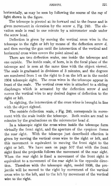
SIGHTS. 521
horizontally, as may be seen by following the course of the ray of light shown in the figure.
The teleflcope is pivoted at its forward end to the frame and is given movement in elevation by the screw e, Fig. 240. The elevation scale is read to one minute by a micrometer scale under the screw head.
Deflection is given by moving the vertical cross wire in the telescope to the right or left by means of the deflection scrm': d, and then moving the gun until the intersection of the vertical and horizontal cross wires covers the point aimed at.
There are two deflection scales, one inside the teleflcope and one outside. The inside scale, of horn, is in the focal plane of the telescope and is seen at the same time with the object viewed. The scale is graduated in divisions of 3 minutes, and the degrees are numbered from 1 on the right to 5 on the left as in the model 1904 telescopic sight. The cross wires in the telescope appear in front of the scale. The vertical cross wire is attached to a sliding diaphragm which is actuated by the deflection screw d and moves the vertical wire to any desired degree of deflection to the right or left.
In sighting, the intersection of the cross wires is brought in line with the object sighted.
The outside deflection scale, s Fig. 240, corresponds in movement v,ith the scale inside the telescope. Both scales are read to minutes by the graduations on the micrometer head d.
In a telescopic sight the cross wires inside the telescope form virtually the front sight, and the aperture of the eyepiece forms the rear Eight. With the telescope just describedd eflection is given by moving the vertical cross wire to the right or left, and this movement is equivalent to moving the front sight to the right or left. We have seen on page 507 that with the front sight fixed the projectile follows the movement of the rear sight. When the rear sight is fixed a movement of the front sight is equivalent to a movement of the rear sight in the opposite direction. Therefore with the telescopic sight, model 1898, the projectile will be moved to the right by movement of the vertical cross wire to the left, and to the left by movement of the vertical wire to the right.

522 ORDNANCE AND GUNNERY.
297. The Power and Field of View of Telescopes.-The power of a telescope, the ratio of the apparent angle subtended by any object to the actual angle which the object. subt.ends, may be obtained by dividing the aperture of the object lens by the aperture of the eye lens. The teleRcope of the model 1904 sight has an objective with an aperture of 3 inches. The eye lens of one of the eycpiec0s provid.ed has an aperturr of t of an inch. The power of the telescope with this eyepiece is therefore 12. In the telescope of the model 1898 sight the aperture of the objective is 1 t inches and of the eye lens ! of an inch. The telescope has therefore approximately a power of 8.
The eye receives the maximum amount of light through a telescope when the diameter of the pencil of light emerging from the eyepiece is equal to the diameter of the pupil of the eye. In the normal eye t.he diameter of the pupil varies approximately from t of an inch to t of an inch, according as there is much light or Ii ttle.
The field of view of a telescope is equal to the field of the eyepiece divided by the power of the telescope. The telescope of the model 1898 sight has a power of 8 and its eyepiece has a field of 48 degrees. The field of view of the telescope is therefore (j degrees.
The field of view of the same telescope with different eyepieces varies practically in inverse ratio to the power of the telescope.
298. Aiming Mortars.- Mortars, both field and seacoast. are as a rule located out of view of their targets and usually behind high shelter. Seacoast mortars are permanently emplaced. Their carriages are provided with graduated azimuth circles by means of which the piece may be laid at any given angle with the meridian plane. The angle made with the meridian plane by the line to the t.arget is determined by means of range and position finders. The piece is then laid at that angle by means of the graduations on the azimuth circle, and correction is made for drift and deviation due to the winc!.
For giving dir~ction to field and sl~ge mortars the vertical plane through gun and target is established by stakes, or by trestles with plumb lines, set up either in front of or behind the mortar in such a position that both gun and target are in view. The axis of the

SIGHTS. 523
mortar is brought into this plane or into any det.ermined position with respect to the plane, and the first round is fired. Correction for error in direction is afterwards made by means of marks on the platform.
The Gunner's Quadrant.-Elevation is given to mortars by IIleans of the gunner's quadrant shown in Fig. 241. The movable
Li.nt! of Fire-Depression ,."
FIG. 24 l.
arm b ~arries a spirit level ami may be set at any desired angle with the base of the instrument up to 65 degrees. The notched scale fixes posit.ions for the arm b at whole degrees . Minutes are obtained by sliding the level along the scale on the curvet \ arm b. The principle of the sliding level on the curved arm vvill be readily understood by reference to Fig. 242 .
The quadrant may be used to measure angles of elevation or of depression from 0 to 65 degrees.
FIG. 242.
The quadrant, set to any desired angle of elevation, is placed on the gun on a seat prepared for it parallel to the axis of the piece. The instrument is so placed thfl,t the proper arrow on its

524 ORDNANCE AND GUNNERY.
base points in the direction of the line of fire. The piece is then elevated until the bubble of the level is in the middle of t.he tube.
By placing the instrument on a vertical seat, as for instance the face of the breech or muzzle of a gun, angles greater than 25 degrees from the vertical may be measured. The angle is obtained by subtracting the reading of the quadrant from 90 degrees.
To facilitat.e the elevating of the mortar the quadrant is now, on mortars mounted on the model 1896 carriage, permanently fixed to a seat provided on the right rimbase of the mortar. The level is fixed on the movable arm of the quadrant, and minutes of elevation are obtained through movement of the arm by means of a tangent screw at its end.

CHAPTER XIV.
RANGE AND POSITION FINDING.
299. Definitions.-A range finder is an instrument for determining the range from the observer to any distant object.
A position finder is an instrument for determining the position of an object with respect to any plane or line, as the meridian plane for guns of position or the front of a battery for mobile artillery.
An instrument adapted to perform both functions becomes a range and position finder.
Range Finders.- -vVith all practical range finders the determination of the range comes from the solution of a triangle. The target is the apex of the triangle. The base of the triangle is laid off either vertically or horizontally from the instrument, and the angles at the extremities of the base are determined, one or both of them, by means of the instrument.
In determining any fixed range the effect of an error in thft measurement of an angle at the base of the triangle will diminish as the length of the base increases. This is apparent from Fig. 243. A given range ot is less affected by an angular error tbe made at the end of the base ob than by an equal error tae made at the end of the O'---~---..3. shorter base oa . FIG. 243.
It is therefore always desirable to use as
r,
long a base as can be conveniently obtained . For this reason horizontal base lines are preferred, since the vertical base of any range finder is limited in length to the height of the instrument above the water.
525

526 ORDNANCE AND GUNNERY.
Consequently in seacoast fortifications, if the surroundings afford convenient sites Jor the angle measuring instruments, the range finding system consists of two t.ransits or azimuth instruments established at the ends of a long base. Observations are made on the target from both enos of the base. The position of the target is plotted on a chart, and its range and position determined for any gun. If the target is moving, simultaneous observations are made from both enels of the base at periodic intervals. The readings of the instruments are transmitted by telephone or t.elegraph to a plotting room in the fortification, where the successive positions of the target are marked on the chart. From the plotted course prediction may be made as to the position the target will occupy at some determined instant in advance, and the range and azimuth of the target at the selected instant may be determined for any gun or battery in the fortification.
300. Depression Range Finders.- --The principle employed in the depression range finder will be understood from Fig. 244.
t~ --_ ..
FIG. 244.
The instrument, at a known height above the sea level, measures the vertical anglr to any object. From the fixed height each angle corresponds t.o a certain length of base,
which is the horizontal range to the object.. " The range in yards is indicated on a scale which is moved past
an index by the same mechanism that gives angular movement to the line of sight.
A difference in the sea level due to the action of tides will affect the height of the instrument above the sea level and consequently the range corresponding to any angle, t amI tf, Fig. 244. Means are therefore provided for aJjustment of the instrument for variations in its height above sea level.
The instrument is made a position fmder by being mounted so as to revolve on a fixed base which is graduated in degrees and hundredths, t.he zero graduation being placed in the meridian plane.
Swasey Depression Range and Position Finder.-The depressioll rango and position finder now usc(l in our ser"vice is shown in Fig. 245. The observing telescope, similar in construction to


Page 526b Back of Fig. 245 Faces Page 527

RANGE AND POSITION PlNDlNG. 527
the telescope of the model 1904 sight, is mounted in a frame which revolves about a central spindle s project.ing upward from the pedestal. The telescope is pivoted near its front end, and is supported near its rear end by the attached bar v which rests on a stud · projecting from the carriage a. The carriage a is mounted on the forward arm of a hent lever l which is pivoted at o. The lower vertical arnl of the lever is connected by gearing with the operating shaft, not seen in the figure. Turning the operating shaft moves the lower end of the lever l, and thus gives vertical movement to the telescope about its forward pivot. The range drum enclosed in the casing d, and visihle through the window w in the casing, is given motion by the same shaft, and the scale on the drum indicates the range corresponding to any position of the telescope. The azimuth is . read from a graduated scale seen through the window z.
The carriage a may be moved along the upper arm of the lever to adjust the position of the telescope for any height above sea level. The height scale along which the carriage moves reads from 40 to 400 feet. Corrections may be made, by moving the carriage, for the change in height of the instrument due to the change in sea level caused by the tides.
301. The Plotting Room.-The range and azimuth of any selected target, as determined by either range finder system, is communicated to the plotting room. In this room are assembled all the instruments necessary for the complete determination of the elements of sighting for the directing gun in the battery whose fire is directed from the room. The corrections to be applied to the observed range to compensate for the effect of the wind, of the thermometric and barometric conditions, of differences in tide level, and of the motion of the target, arc quickly determined from the instruments for a predicted position of the target at some instant in advance. The deviation due to the wind and drift and motion of the target are also determined. The corrected range, azimuth, and deviation are sent to the gun, and the gun is then pointed according to the instructions received. The command to fire is given at such a moment as to cause the shot to arrive at the predicted position of the target at the same instant as the target.
The instruments used are as follows.

528 ORDNANCE AND GUNNERY.
The wind component 1,ndicator gives the components of the wind for range and deflection for use on the range and deflection boards. The azimuth of the wind's direction, taken from the wind dial, and the velocity of the wind, taken from an anemometer, are laid off on the instrument. The azimuth of the target is also laid off, and the instrument then indicates by a pointer the range and deflectIon components of the wind with respect to the line from the gun to the target.
The atmosphe1'e board indicates the correction to be applied at the range board for thermometric and barometric changes.
The range board, with the data supplied by the foregoing instruments and other data indicated below, gives the corrections in yards to be applied to the range for wind, atmosphere, tides, and variations from the standard muzzle velocity, and indicates the sum of these corrections.
The plotting board converts the range and position of the target as determined from the reports of the range and position finders, to the range and position for the particular battery or gun, with the correction for range determined by the range board.
The defiection board indicates, for the corrected range and azimuth from the plotting board, the sum of the deflections to · be applied to the sight, or to the azimuth of the piece, to correct for the deviating effect of wind, drift, and the motion of the target.
By means of these instruments, which have been devised by artillery officers of our army, the correct setting of a gun may be determined, the gun aimed, and the shot sped on its way, in an interval of 15 seconds. The instruments arc simple in construction and manipulation, and their use is entrusted to the enlisted soldier.
302. Field Range and Position Finding.-For range and position finding in the field there are provided the Weldon range finder, the battery commander's telescope, the battery commander's ruler, and the field plotting board. The uses of these instrunl0nts will be understood from their descriptions.
The Weldon Range Finder.-·The Weldon range finder, Fig. 246, consists of three triangular prisms mounted in a metal frame. The silvered base of each prism rests against the metal. The angle at the apex of each prism is as follows.

RANGE AND POSITION FINDING.
The upper or first prism, 90 degrees The second prism, 88° 51' 15" The third prism, 74° 53' 15"
529
Now if we construct, as in Fig. 247, the first two of th~ above angles at the end of a base ""hose length is unity, and the third
FIG. 247.
a
FIG. 246. FIG. 248.
angle as shown in the figure, the sides of the resulting triangles will be of the lengths marked on them in the figure, the sides being proprtional to the sines of the oppm;ite angles.
Each prif;m diverts a ray of light through an angle equal to the angle at its apex, as may bo seen from Fig. 248. A ray entering the first prism from t or a iRsues from the prism in a direction perpendicular to its original direction. And similarly a ray will issue from the second prism at an angle of 88° 51' 15" with its original direction.

530 ORDNANCE AND GUNNERY.
St.anding at a, Fig. 249, and looking into the first prism, we see t.he image of the object t in the direction ad, perpendicular to at,
i and at the same time looking over
~ the prism we sec the object d in line
t . a with t.he image of t. Now moving
~ ,~: ::in~: ~:eth~ l::~h:l ~: FIG. 249. target t, seen in the second prism,
will again align with the object d seen over the prism. The angle tba is then 88° 51' Hi" and at, the range to the target, is 50 times the base ab, see Fig. 247.
The second prism may be used at both ends of the base. The triangle abt will then be an isosceles triangle, the angle at a being equal to the angle at b, and the length of the sides at and bt will be 25 times the length of the base.
The third prism is provided for use when the base ab is inconveniently long or when through the interposition of a gulch or other obstacle the length of the base can not be directly measured.
The points a and b, Fig. 249, having been determined, the observer moves on the line tb to some point c from which, looking in the tMrd prism, he sees the image of the point a covering the object at t seen over thrl prism. The angle at c is then 74° 53" }'5', and as shown in Fig. 247 the base cb is one quarter of the base ab or 1/200 of the range at.
It is apparent from Fig. 248 that the instrument may be u~ed with the apex of the prism toward the eye or toward the target, since both t and a may represent either target or eye. The position of the image in either case with respect to the apex of the prism is indicated in the figure.
The true refracted image may always be distinguished from images reflected from the face of a prism by revolving the instrument about a vertical axis. Refleeted images revolve with the instrument, but as t.he lateral refradion is a fixed one the refracted image remains stationary when the instrument is revolved.
When the instrument is held with the compass needle pointing north, the bottoms of the two notches in the middle of the cover mark the east ann west line; and these two notches together with

RANGE AND POSITION FINDING. 531
the two at the end of the cover mark diagonal lines running northeast and northwest.
303. The Battery Commander's Telescope.-The battery commander's telescope, Fig. 250, is mounted on a tripod in the same
~~~--------~ ....... '" ~'wl'""","¥J1ne,---
El"",,"¥ ,J"""u----..,------.--j I ,
.----..Az/muth Tan9fHll ,J'brrla1---, , , ,)~c:~~~ r-~.zinru.t"~-------l t __ ~ .. J I _______ ._~ __ '!':-_ ~1!IIe""""'=='u;l
FIG. 250.
manner as the telescope of a transit instrument. It has movement about horizontal and vertical axes. The amounts of the movements about the axes are indicated by scales graduated to 6400ths of the circle, or mils, corresponding for horizontal movement to the deflection scale of the panoramic sight, and for vertical movement to the clinometer scale of the range quadrant.
The telescope forms an erect magnified image of the object. The ray of light enters the window in front of the objective prism, is reflected downward by this prism, which is one of total reflection,

532 ORDNANCE AND GUNNERY.
passes through the ohjective, is rectified by the two Porro prisms, and forms the image in the plane of the cross hairs in front of the eyepiece.
The objective has a clear aperture of It inches, and a focal length of 11 inches. The power of the telescope is 10, and the field of view is 4 degrees.
The hattery commander's telescope is used for measuring both horizontal and vertical angles; horizontally, the azimuths between the target, gun, and aiming point, the azimuth of the front of a hm~tile position, the correction in azimuth required to bring the shots from a hattery on to the target; and vertically, the angle of position of the target, the correction in elevation required to bring the projectile to the target or the burst of the shrapnel to the proper height above the target.
304. The Battery Commander's Ruler.-The battery · commander's ruler, Figs. 251 and 2.52, constructed after the manner of the slide rule, provides on the front, Fig. 2,51, a scale for quickly measuring azimuths and a slide rule for determining the height of the trajectory in mils at any point of the range, and on the back, Fig. 2.52, a table of parallaxes, computed for a base of 20 yards, for several ranges and for different angles of obliquity of base to range.
The instrument is of brass about 6 inches long, 1 inch wide, and k of an inch thick.
A cord about 2 feet long passes through a hole in the ruler. One end of the corel is fastened to a button on the observer's coat so that Wh011 the ruler is held out until the cord is taut the ruler is 20 inches from the observer's eye.
The scales on either edge of the front of the ruler are graduated to read azimuths in mils. To measure any angle in azimuth, as for inst.ance from the target to the aiming point, the ruler is held horizontally at the length of the cord with the zero at the end marked T in line with the target. The azimuth to the aiming point is indicated on the scale at the point where the line from the eye to the aiming point cuts the edge of the ruler. It will be seen that azimuths to the right of the target read from 0 to 300, and azimuths to the left read from 6100 to 6400, corresponding to the deflection scaleR of the sights. The ruler is always held with that

j-,s'lldo-G'rattua&edforKel;th&et' 7h!f'et:'rozy InUits r:>4zlm/dh ,s'caIe- dnrduotett to f1Iue Azinutlhs in Mlis--- --.." I I I I I I I I rli"',C'i'X:'*"li'ilj~IXi'lj"~"'X"il'i"liill"il" 'XiiX"li"'l'i"I"l'i"lii"£"k"li"!J)"it'il""J:"l111~lil'~ ).
n . -II ; I I I I I 1
,L-,~llltl!!f!I:(!!tlllt!lltIII1\11J.111t.lltll,t!II"7(,!g!!11~II!tll.i.!ISI!!.f!I!y.IIItII'!fI!ltll!t'j!f!ll!r!!I!t ~ .... _-----
FIG. 251.
/ /011. 51?
0IT9TTSfffiB'7JT5 11
T3TI n
1.?J'f.?212! 7,
t I&'w[UW J'.914t714'/1~ 46
L~~7a,6le FIG. 252.
Battery Commander's Ruler.
~
s: ~
~ ~
8
~ :j
~ '>j
~
~ ~
Clt
~

534 ORDNANCE AND GUNNERY.
edge up that will give a reading in the desired direction from the mark T on the sca,le. All desired azimuths are similarly measured. The ruler will be used for these measurements when the more 'accurate battery commander's telescope is not at hand.
THF. Sr"ID'F..-' The slide and the adjacent range scale on the ruler provide the means for determining the height of the trajectory in mils at any given point of the range. This information may he frequently required for use in ascertaining whether an intervening obstade such as a hill, or woods, or a tower, will interfere with the fire at a given target, or in determining the extent behind the ohstacle that is masked from the fire of the gun. The slide is graduated in mils from -24 through 0 to + 284, The adjacent range scale on the ruler is in hundreds of yards. -
To usc the instrument, first determine the angle of position of the target, in mils, by the battery commander's telescope or otherwise. Move the slide so as to place the slide graduation that indicates the angle of position of the target over the range of the obstacle as indicated on the ran go scale. The height of the trajectory at the obstacle, in mil"!, is then indicated on the slide opp()site the range of the target on the range scale. If the height indicated is greater than the angle of position of the obstacle, obtained in the same manner as the angle of positioll of the target, the projectile will clear the obstacle.
The principle involved in the use of the slide will be understood from Fig. 253, in which the 6OOO-yard trajectory of the 3-
FIG. 253.
inch rifle is represented. The angular heights of the successive points of the trajectory, measured from the origin, evidently dimini<;h from the angle of departure if> at the origin to zero at the end of the range. Under t.he principle of the rigidity of the tra-

RANGE AND POSITION FINDING. 535
jectory we may assume with sufficient exactness that within the limits of direct fire any portion of the trajectory from the origin is the true trajectory for the range represented by its chord. We may therefore assume the portion of the trajectory subtcnded by the shorter chord in the figure as the true trajectory for the range 3200 yards, and from the figure we see that the angular height of the 6000-yard trajectory at 3200 yards is the angle of departnre cf> for 6000 yards minus the angle of departure 1/ for 3200 yards.
On the range scale under the slide, Fig. 2.51, the zero of the two scales being together, each range is indicated opposite its correflponding angle of departure as indicated in mils on the ~lide.
Thus the angle of departure for a range of 3200 yards is nearly 100 mils, 100 /6400 of 360 degrees, or 5° 37'.
A movement of the slide in either direction will cause the reading above any range to he increased or diminished; that is, the movement adds an angle to the angle of departure for the range, or subtracts an angle. If the zero of the slide is moved to the 3200-yard mark on the range scale, the angle of departure for 3200 yards is subtracted from the reading over every range on the scale. Therefore the angle of departure for, say, the 6000-yard rallge is diminished by the angle of departure for 3200 yards, and as shown in Fig. 253 this difference, indicated on the slide over the 6000-yard mark on the range scale, is the height of the 6000-yard trajectory at 3200 yards.
Now if we assume that the line od, Fig. 253, is horizontal and that the target at c is elevated above d by the angle of position e, say 20 mils, it is evident that 20 mils must be added to every reading on the slide. We therefore move the zero of the slide back until the 20 on the slide instead of the zero is now over the range 3200. The reading over every range is increased by 20.
We have now put the angle of position of the target over the range of the obstacle, and oyer the range of the target we read the height of the trajectory at the obstacle.
305. THE PARALLAX TABLE.-·On the back of the ruler, Fig. 252, is inscribed what is called the parallax table. By parallax is meant herE' the angle, in mils, subtended by the front of a platoon, 20 yards, from any point outside the battery. Thus in Fig. 254, a being the aiming point and t the target, the

536 ORDNANCE AND GUNNERY.
parallax of the aiming point is the angle at a subtended by the two guns, and the parallax of the target is the angle at t sub
tended by the guns. The parallax of a point that
lies in a direction normal to the front of the battery is, since 1 mil is 1/1000 of the range, equal to 20 divided by the number of thousands of yards in the range. Thus for 4000 yards the parallax is 5 mils. If the point lies in a
direction oblique to the front of the battery, the parallax is equal to the normal parallax multiplied by the cosine of the angle which the direction of the point makes with the normal to the battery front.
The parallax has been calculated for different ranges and different directions of the point and tabulated on the back of the ruler. The upper two lines of the table, Fig. 252, give the angles of obliquity in hundreds of mils in the two quadrants in front of the battery, the lower two lines give similar angles for the two quadrants in rear. The parallax of any point at anyone of the four ranges marked at the left is found in the line oj the range and in the column that indicates, to the nearest hundred mils, the obliquity of the point's direction. The parallax in any fixed direction is an inverse function of the range, therefore for any range not given in the table it may be readily d(;termined by means of the parallax for some range in the table. Thus the parallax for 3000 yards is half that for 1500 yards or I that for 1000 yards.
By means of the parallax the proper setting of the sight in indirect firing may be detemlined for one gun from the sighting of the adjacent gun. Thus in Fig. 254 if the gun on the right has found the target, at the angle a from the aiming point, the angle {1 for the second gun is readily obtained. Representing by pa and Pt the parallax angles at a and t respectively, we see from the figure that, since
r=a+Pa={1+p~ {1=a+Pa -Pe

RANGE AND POSITION FIN DING. 537
306. Plotting Board for Mobile Artillery.-The plotting board, Fig. 255, 16 inches wide by 39 inches long, is covered with rubber cloth. Across the middle of the board is a grooved guideway g,
its edges graduated in yards. The protractor 0 slides in the guideway. The protractor is graduated in 64ths of a circle and by a vernier may be read to mils. The outer graduated rim of the protractor turns about the fixed central part. Fixed to the outer rim of the protractor is the arm I, and pivoted to the center of the protractor is the arm m, both graduated in yards. On each arm
FIG. 255.
is a sliding index, a. and t, provided with a pin which may be stuck into the board to hold the index in a fixed position.
The plotting board is used at the observing station to determine, for the directing gun, the position of the target with respect to the point selected as an aiming point. Thus in Fig. 254, 0 is the observing point from which the aiming point a, the target t, and the directing gun are visible. The ranges from the observer to the three points are determined, and the angles made by the lines to the points with the line from the observer to the gun. This line to the gun is the datum line, . and is represented on the plotting board by the center line of the grooved guideway. The scale on the edge of the guideway is graduated to yards.
With the protractor in the center of the board, 0 Fig. 2.55, the arm m is placed at an angle with the guideway equal to the angle ~+ e, Fig. 254, and the sliding index on the arm is placed at the range oa. on the scale. Similarly the arm I is revolved to make the angle (J with the guideway, and its index is placed at the range ot on the scale. The pins of the two indexes are stuck into the board.
The protractor is now moved along the guideway to the point

533 ORDN ANCE AND GUNNERY.
on the guideway scale, 0' Fig. 255, that marks the distance from the observer to the gun. The two arms slide through the indexes and assume the positions of the lines from the gun to the aiming point and to the target, Fig. 254. The angle a between the arms is read from the protractor, and the ranges from the gun to the aiming point and target are read from the scales on the arms.
307. Other Range Finders.-Other range finders have been constructed on the principle of the Weldon range finder, using prisms with different angles or producing the deflection of the ray by means of mirrors.
The Berdan Range Finder.-The Berdan range finder consists of two telescopes permanently mounted 6 or 12 feet apart on the bed of a wagon, and provided with graduated circular bases by means of which the angles between each of the telescopes and the base are measured. The shott base renders excessive the effect of a slight error in the measurement of an angle, and for this reason principally the instrument has not heen found satisfactory in service.
The Barr and Stroud Range Finder.-The Barr and Stroud range finder, used on the ships of our own and foreign navies, and now being tested for our field service, is constructed, optically, in the manner shown in Fig. 256. The tube containing the optical
, I I I I I
I ~ ~
t Il , I
! II tr =- . '\i~ I .______ __o!__ II
-~-~-------------------~;=-----t----~~~~ J t"ll L l f
I I
FIG. 256.
parts is so mounted on the deck of the ship, that the target. may be kept in view during heavy rolling or pitching of the ship.
Two reflectors r, marking the ends of a base line 41 feet long, divert the rays from the target through the objectives 0 and thence through the prisms p to the observer's right eye at e. The field of view of the right eyepiece is divided horizontally by a dark

RANGE AND POSITION FINDING. 539
line, Figs. 258 and 259. The image from the objective on the right is formed above this line and that from the left below it.
A cieflecting prism, d Fig. 256, has a sliding movement in the right telescope. When in position at d the prism has no deflecting effect on the ray from the objective, and in this position of the prism the parallel rays a from an object at a great distance, as from the sun or moon, will form a continuous image in the field of the right eyepiece. Now if a nearer object, on the same line from the left reflector, be viewed, the direction of the ray to the light reflector will be changed from a to s and the image from the righ'; telescope will not be continuous with that from the left, Fig. 259.
EBED FIG. 257. FIG. 258. FIG. 259. FIG. 260.
Continuity in the image is obtained by sliding the deflecting prism d to the position c. The amount of the movement of the deflecting prism is dependent. on the range to the object; and the ranges corresponding to the various positions of the prism are marked on a scale that is carried by the prism. A movement of the deflecting prism over a length of six inches corresponds to a change in range from infinity to 250 yards.
The observer looks with his left eye through the eyepiece l, Fig. 256, and through the finder objective f opposite. The left eyepiece and the object lens t form a low powered telescope with a large field of view. The object viewed, Fig. 257, is seen through this telescope, and in the field of view above the object appear a pointer and a portinn of t.he scale that is attached to the deflecting prism d. The range to the object is read from the scale at the pointer.
Fot use at night in obt.aining the range to any t.arget that bears a light an optical appliance callen. an ast'igmahzcr- is provided in the instrument. The astigrnatizer lengthens the imag()s of a point of light into vertical streaks, Fig. 260, and the streaks are brought
540 ORDN ANCE AND GUNNERY.
into coincidence. The astigmatizer is moved aside when not in use.
The Le Boulenge Telemeter.-·The Le Boulenge telemeter i:; an instrument by means of which the velocity of sound is used for measuring distance. The inst.rument is a glass tube filled ,yith liquid. In the t.ube is a loose glass piece or traveler whose specific gravity is but slightly greater than that of the liquid, so that when the tube is held vertical the traveler falls through the liquid slowly and with approximately uniform motion. The time between the flash of a gun and the arrival of the report is measured by turning the tube from a horizontal to a vertical position when the flash is seen, and back to the horizont.al when the report is heard. The range corresponding to the distance that the traveler has fallen in the interval is read from a scale on the tube.
As the velocity of sound, 1100 feet per second in calm air, varies with the velocity and direction of the wind,_ this method of measuring ranges is not satisfactory.

CHAPTER XV.
SMALL ARMS AND THEIR AMMUNITION.
308. Service Small Arms.---Thepresent service small arms are the .38 caliber revolver, model 1903, and the .30 caliber rifle, model 1903. Automatic pistols have been issued to the service for trial within recent years, but the results of the trials have not been sufficiently favorable to bring about the adoption of any of these arms for the military service. Automatic and semi-automatic rifles have also been submitted to the Ordnance Department for test. The tests are now in progress.
The .38 Caliber Revolver.--The service revolver is made by the Colt's Patent Fire Arms Manufacturing Co. of Hartford, Conn., and iN known as the Colt's double action revolver, caliber .38.
A double action revolver is one that may be fired in either of tw 0 ways: by separately cocking the hammer and pulling the trigger, or by performing both operations with a single pull on the trigger. "Vhen the separate movements are employed the piece is said to be used in single action; and in double action, when cocked and fired by the pull on the trigger alone. The service nwolver may be used either in single action or in double action .. Much greater rapidity of fire can be attained using the revolver in double action, but on account of the increa~ed effort required in firing in this manner, and the c~nsequent unsteadiness of the hand holding the revolver, the fire is not likely to be as accurate as when the revolver is fired in f!ingle action.
The mechanisP-l of the revolver is shown in Fig. 261. The operation of the mechanism is briefly as follows. In single action
541

542 ORDNANCE AND GUNNERY.
the piece is cocked by pres .. 'mre of the thumb on the head of the hammer, 18. The lower end of the hammer moves the upper end of the trigger forward and upward until the upper edge of the trigger engages under the lip at the lower end of the hammer and holds the hammer in the cocked position. A pull on the trigger will then release the hammer, which, under the action of the mainspring 32, falls and explodes the cartridge. The pressure on the trigger being released, the . rebound-lever spring 37
acting on the rebound-lever 34 moves the hammer back slightly to its safety position and at the same time moves the trigger forward.
When firing in double action the pull on the trigger causes the upper end of the trigger to bear against the end of the strut 10 which is pivoted on the pivot of the hammer and bears against the hammer above the pivot. The pull on the trigger thus lifts the hammer until, VI" hen the hammer is nearly at full cock, the strut escapes from the end of the trigger and the hammer falls. As the rear part of the trigger moves upward, whether in single or in double action, the upper end of the hand 25 engages in a notch on the r~ar face of the cylinder and causes the cylinder to revolve thrcv;;h one-sixth of a turn. At the last part of the movement

SMALL ARMS AND THEIR AMMUNITION. 543
of the trigger a projecting lug forward on its upper surface passes through a slot in the frame and engaging in a notch in the cylinder prevents further movement of the cylinder.
The mechanism includes safety devices which allow the piece to be cocked only when the cylinder is fully closed and latched in the proper position.
309. THl~ MAINSPRING TENSION SCREw.-The mainspring tension screw 33 is an important part of the mechanism whose functions are not usually understood. It"! purpose is to vary the tension of the mainspring in order to adjust the force of the blow delivered by the hammer on the primer of the cartridge. When the revolver is used in double action the hammer is not retracted as far as in single action and consequently delivers a lighter blow on the primer. It is a difficult matter to manufacture a primer suitable for both methods of firing. If the cap of the primer is made thin enough to insure firing of the primer under the lighter blow in double action, the metal of the cap is likely to be pierced by the point of the hammer under the heavier blow in single action. The pierced primer allows the powder gases to escape to the rear, perhaps to the injury of the soldier. If on the other hand the primer cap be made sufficiently · thick to insure its not being punctured by the heavier blow, the primer may not be sufficiently sensitive to be always fired by the lighter blow. The importance of a proper adjustment of the tension of the mainspring is therefore apparent. If it is found that failures to fire in double action are frequent the screw 33 should be screwed in slightly to increase the tension of the mainspring and produce a heavier blow of the hammer. But the tension must not be increased more than absolutely necessary, for otherwise puncture of the printer may occur when the revolver is fired in single action.
THE BARREI...~The barrel of the revolver has a length of 6 inches, and a diameter between the lands of the rifled bore of 0.357 of an inch. It is rifled with 6 grooves 0.003 of an inch deep and with a uniform twist of one tum in 16 inches. The rifling has a left handed twist in order that the drift of the bullet to the left may counteract to some extent the tendency that exists to pull to the right in firing.

544 ORDNANCE AND GUNNERY.
AMMUNITION AND BALLlSTIcs.- The ball and blank cartridges used in the revolver are shown in Fig. 262. The charge in the ball cartridge is about 3t grains of a nitroglycerine powder, and
produces in the bullet a muzzle velocity of 750 feet. The bullet, of lead, weighs 148 grains. Its greatest diameter is 0.357 of an inch, which is the diameter bet,veen the lands of the rifleJ bore. The powder gases entering a conical cavity in the base of the bullet expand the base of the bullet into the grooves of the rifling. The grooves of the bullet are filled with Japan
I!;;;;;;;;;;;;;;;;;!J wax as a lubricant. The wax also serves, to-FIG. 262. h' h h .. f get or WIt t e cnmpmg 0 the front end
of the cartridge case against the bullet, to keep out moisture and render the cartridge ,vaterproof. '
'Vhilc the bullet has sufficient energy to inflict a disabling wounrl at a range of 200 yards, the revolver cannot be relied upon for accurate firing beyond 75 yards.
The blank cartridge contains 7 grains of E. C. po'\vder held in the case by a paper wad crimped in place and shellacked .
310. The Colt Automatic Pisto1.-In the Colt automatic pistol the recoil of a movable barrel and slide is utilized to eject the fired shell, cock the firing mechanism, and load a new cartridge into the barrel; so that after the first shot is fired the only operation necessary to fire the remaining cartridges in the magazine is a pull of the trigger for each cartridge .
. The pistol is made in three calihers, )32, .3R, and .45. The magazines of the two· smaller pistols hold 8 cartridges; that of the .45 caliber pistol holds 7 cartridges. The.45 caliber pistol is represented in Fig"S. 263 to 265. The rear part of the frame or receiver r forms a hollow han<lle which encloses the magazine and the firing mechanism. The magazine, Fig. 264, is a light metal case containing a spring and follower. The cartridges are inserted one at a time by sliding in at the top. The sides of the magazine curve slightly over the upper cartridge, which may be removed only by being pushed out to the front. The magazine when filled is inserted into the handle of the pistol from below and is held in place by a spring catch.