Extending the Life of Lithium‐Based Rechargeable … through the separator thereby extending the...
6
COMMUNICATION © 2016 WILEY-VCH Verlag GmbH & Co. KGaA, Weinheim wileyonlinelibrary.com (1 of 6) 1603987 Extending the Life of Lithium-Based Rechargeable Batteries by Reaction of Lithium Dendrites with a Novel Silica Nanoparticle Sandwiched Separator Kai Liu, Denys Zhuo, Hyun-Wook Lee, Wei Liu, Dingchang Lin, Yingying Lu, and Yi Cui* DOI: 10.1002/adma.201603987 engineering of electrode materials, [17–21] electrolytes, [22–29] sepa- rators, [16,30–41] thermal-switching current collectors, [42] and bat- tery management systems. [6] Herein, we have developed a novel trilayer separator to extend the life of lithium-based recharge- able batteries. As shown in Figure 1, a layer of silica nano- particles is sandwiched by two layers of commercial polyolefin separators. It has been well studied that silica nanoparticles can electrochemically react with lithium metal. [43–45] Therefore, it is anticipated that when lithium dendrites grow and penetrate the separator, they will contact the silica nanoparticles in the sand- wiched layer. The silica nanoparticles will react with Li through a solid-state conversion reaction, thus efficiently etching away dangerous Li dendrites and slowing their further growth. By doing so, it will delay the time for lithium dendrites to pene- trate through the separator thereby extending the life of battery. It should be noted that there are four properties which make the sandwiched trilayer separator novel and efficient: (1) In this sandwiched configuration, the silica nanoparticles will not be in direct contact with the lithium metal anode, so the silica nanoparticles will not be lithiated until dangerous dendrites have already penetrated inside the separator. Thus the unneces- sary consumption of lithium metal by silica is avoided during normal function. (2) The packing of spherical silica nanoparti- cles will create a highly porous structure inside the sandwiched layer, which can facilitate the transport of lithium ions and good penetration of the electrolyte inside the separator. More- over, silica nanoparticles have polar groups on their surface and therefore have a better wettability to the polar electrolyte. [35] Thus, the introduction of a sandwiched silica layer will not increase the resistance of the battery significantly. (3) The silica is electrically insulating. Thus, even when the lithium dendrites contact the silica, the reduction of lithium ions will be confined only to the existing dendrites. If the nanoparticles are conduc- tive to electrons, the location of dendrite formation and growth cannot be controlled as the nanoparticles are interconnected throughout the sandwiched layer. The uncontrolled forma- tion and growth of dendrites inside a conductive nanoparticle network may even deteriorate the situation and decrease the battery life. (4) Silica is very cheap and the production of this trilayered separator is quite simple and straightforward, which makes it compatible with traditional battery production. We note that our conceptual design of a reaction-protective separator is different from ceramic-coated polymer separa- tors. [16,34,38–41] (1) For ceramic-coated separators, ceramic nano- particles are generally coated on one or both sides of the sepa- rator where the nanoparticles will directly contact the anode/ cathode, leading to undesirable electrochemical side reactions. However, in our design, the silica nanoparticles are sandwiched Dr. K. Liu, D. Zhuo, Dr. H.-W. Lee, Dr. W. Liu, D. Lin, Dr. Y. Lu, Prof. Y. Cui Department of Materials Science and Engineering Stanford University Stanford, CA 94305, USA E-mail: [email protected] Prof. Y. Cui Stanford Institute for Materials and Energy Sciences SLAC National Accelerator Laboratory Menlo Park, CA 94025, USA Electrochemically rechargeable batteries, especially lithium- based rechargeable batteries have attracted significant attention in recent years. [1–4] Although the performance of lithium bat- teries continues to improve, their energy density and cycle life remains insufficient to meet increasingly demanding require- ments, particularly for future large-scale renewable energy storage and electric grids, electric drive vehicles, airplanes, and next-generation portable electronics. [1,2,4,5] In this regard, lithium metal is considered the optimal choice for anode mate- rial because it has the highest specific capacity (3860 mAh g −1 ) and the lowest anode potential (−3.04 V vs standard hydrogen electrode). [5–9] Despite these advantages, lithium metal anodes suffer from short cycling life and safety issues, as lithium can easily form dendritic and mossy metal deposits. [10,11] In addi- tion, lithium dendrite formation has not been entirely inhib- ited in commercialized graphite anodes which are much safer, especially when operated at high current densities, in overcharge conditions, or at low temperatures. [6,12–15] The den- drites can short-circuit the battery by gradually grow bigger and penetrating the embedded small pores of the inert polymer separator. When the dendrites finally connect the cathode and anode, the battery is short-circuited and there is danger of catching fire. [16] The formation and growth of dendrites is not only a safety concern but also reduces the energy storage and conversion efficiencies, which is a big obstacle for the prac- tical application of lithium metal anodes. The situation can be exacerbated if there are small perforations or pinholes in the separator which can be difficult to detect and are inevitably created during the separator production and battery assembly processes. The existence of pinholes can increase the local lith- ium-ion flux due to the much decreased resistance across the separator, creating “hotspots” near the area of the pinhole for increased lithium metal deposition on the lithium electrode. [17] This greatly accelerates the formation and growth of lithium dendrites and the consequent failure of the battery. In order to extend the life of the battery and improve their safety, considerable efforts have been devoted to delicate www.advmat.de Adv. Mater. 2017, 29, 1603987 www.advancedsciencenews.com
Transcript of Extending the Life of Lithium‐Based Rechargeable … through the separator thereby extending the...

Co
mm
un
iCatio
n
© 2016 WILEY-VCH Verlag GmbH & Co. KGaA, Weinheim wileyonlinelibrary.com (1 of 6) 1603987
Extending the Life of Lithium-Based Rechargeable Batteries by Reaction of Lithium Dendrites with a Novel Silica Nanoparticle Sandwiched Separator
Kai Liu, Denys Zhuo, Hyun-Wook Lee, Wei Liu, Dingchang Lin, Yingying Lu, and Yi Cui*
DOI: 10.1002/adma.201603987
engineering of electrode materials,[17–21] electrolytes,[22–29] sepa-rators,[16,30–41] thermal-switching current collectors,[42] and bat-tery management systems.[6] Herein, we have developed a novel trilayer separator to extend the life of lithium-based recharge-able batteries. As shown in Figure 1, a layer of silica nano-particles is sandwiched by two layers of commercial polyolefin separators. It has been well studied that silica nanoparticles can electrochemically react with lithium metal.[43–45] Therefore, it is anticipated that when lithium dendrites grow and penetrate the separator, they will contact the silica nanoparticles in the sand-wiched layer. The silica nanoparticles will react with Li through a solid-state conversion reaction, thus efficiently etching away dangerous Li dendrites and slowing their further growth. By doing so, it will delay the time for lithium dendrites to pene-trate through the separator thereby extending the life of battery. It should be noted that there are four properties which make the sandwiched trilayer separator novel and efficient: (1) In this sandwiched configuration, the silica nanoparticles will not be in direct contact with the lithium metal anode, so the silica nanoparticles will not be lithiated until dangerous dendrites have already penetrated inside the separator. Thus the unneces-sary consumption of lithium metal by silica is avoided during normal function. (2) The packing of spherical silica nanoparti-cles will create a highly porous structure inside the sandwiched layer, which can facilitate the transport of lithium ions and good penetration of the electrolyte inside the separator. More-over, silica nanoparticles have polar groups on their surface and therefore have a better wettability to the polar electrolyte.[35] Thus, the introduction of a sandwiched silica layer will not increase the resistance of the battery significantly. (3) The silica is electrically insulating. Thus, even when the lithium dendrites contact the silica, the reduction of lithium ions will be confined only to the existing dendrites. If the nanoparticles are conduc-tive to electrons, the location of dendrite formation and growth cannot be controlled as the nanoparticles are interconnected throughout the sandwiched layer. The uncontrolled forma-tion and growth of dendrites inside a conductive nanoparticle network may even deteriorate the situation and decrease the battery life. (4) Silica is very cheap and the production of this trilayered separator is quite simple and straightforward, which makes it compatible with traditional battery production.
We note that our conceptual design of a reaction-protective separator is different from ceramic-coated polymer separa-tors.[16,34,38–41] (1) For ceramic-coated separators, ceramic nano-particles are generally coated on one or both sides of the sepa-rator where the nanoparticles will directly contact the anode/cathode, leading to undesirable electrochemical side reactions. However, in our design, the silica nanoparticles are sandwiched
Dr. K. Liu, D. Zhuo, Dr. H.-W. Lee, Dr. W. Liu, D. Lin, Dr. Y. Lu, Prof. Y. CuiDepartment of Materials Science and EngineeringStanford UniversityStanford, CA 94305, USAE-mail: [email protected]. Y. CuiStanford Institute for Materials and Energy SciencesSLAC National Accelerator LaboratoryMenlo Park, CA 94025, USA
Electrochemically rechargeable batteries, especially lithium-based rechargeable batteries have attracted significant attention in recent years.[1–4] Although the performance of lithium bat-teries continues to improve, their energy density and cycle life remains insufficient to meet increasingly demanding require-ments, particularly for future large-scale renewable energy storage and electric grids, electric drive vehicles, airplanes, and next-generation portable electronics.[1,2,4,5] In this regard, lithium metal is considered the optimal choice for anode mate-rial because it has the highest specific capacity (3860 mAh g−1) and the lowest anode potential (−3.04 V vs standard hydrogen electrode).[5–9] Despite these advantages, lithium metal anodes suffer from short cycling life and safety issues, as lithium can easily form dendritic and mossy metal deposits.[10,11] In addi-tion, lithium dendrite formation has not been entirely inhib-ited in commercialized graphite anodes which are much safer, especially when operated at high current densities, in overcharge conditions, or at low temperatures.[6,12–15] The den-drites can short-circuit the battery by gradually grow bigger and penetrating the embedded small pores of the inert polymer separator. When the dendrites finally connect the cathode and anode, the battery is short-circuited and there is danger of catching fire.[16] The formation and growth of dendrites is not only a safety concern but also reduces the energy storage and conversion efficiencies, which is a big obstacle for the prac-tical application of lithium metal anodes. The situation can be exacerbated if there are small perforations or pinholes in the separator which can be difficult to detect and are inevitably created during the separator production and battery assembly processes. The existence of pinholes can increase the local lith-ium-ion flux due to the much decreased resistance across the separator, creating “hotspots” near the area of the pinhole for increased lithium metal deposition on the lithium electrode.[17] This greatly accelerates the formation and growth of lithium dendrites and the consequent failure of the battery.
In order to extend the life of the battery and improve their safety, considerable efforts have been devoted to delicate
www.advmat.de
Adv. Mater. 2017, 29, 1603987
www.advancedsciencenews.com

Co
mm
un
iCati
on
© 2016 WILEY-VCH Verlag GmbH & Co. KGaA, Weinheimwileyonlinelibrary.com1603987 (2 of 6)
between two inert polymer separators. Thus, the silica/lithiated silica (after Li dendrite penetration) is not in contact with the active anode/cathode, e.g., Li metal. (2) In previously reported work, the physical properties of the ceramics are generally leveraged by coating them onto the separator to improve the thermal stability, electrolyte wettability, etc. However, in our work, we also employ the lithium-reactive chemical properties of the ceramics to consume lithium dendrites and significantly extend the battery life. (3) In our work, the incorporation of the silica nanoparticles inside the sandwiched structure makes the separator more robust. This is in contrast to single or double side coated separators where the nanoparticles are directly exposed on the surface and may detach from the separator during battery assembly.
Silica nanoparticles were synthesized by a traditional sol–gel method.[46] Using this method, spherical silica nanoparticles with a diameter of ≈400 nm were facilely obtained as shown in Figure S1 (Supporting Information). A layer of silica nanopar-ticles was then coated onto 12 µm thick conventional porous polyolefin separators using a small amount of polyvinylidene difluoride (PVDF) as a binder. The trilayered separator was pre-pared by stacking two silica coated separators, where the silica layers on both separators contact and face each other. The as-prepared trilayer separator is quite uniform and the thickness of the silica layer is around 20 µm. The silica nanoparticles are closely packed as indicated by the scanning electron micros-copy (SEM) images in Figure 1c,d. To determine whether the incorporation of the silica layer increases the resistance signif-icantly, we measured the impedance of the trilayer separator. For comparison, two conventional porous polymer separators were stacked as a control, i.e., bare separators. Figure S2a (Sup-porting Information) shows the Nyquist plots obtained from
electrochemical impedance spectroscopy (EIS) for silica-coated and bare separator. The corresponding resistance for the bare separator (4.2 Ω) and trilayer separator (5.1 Ω) are shown in Figure S2b (Supporting Information). Thus, the introduction of the silica sandwiched layer does not increase the ionic resist-ance significantly.
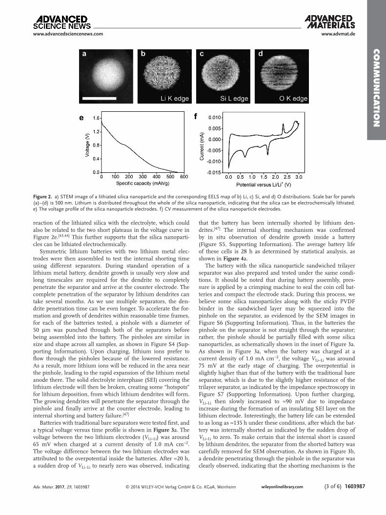
To evaluate whether the silica nanoparticles can be elec-trochemically lithiated, a silica nanoparticle-Li metal half cell was prepared. The cell was discharged to a potential of 0.01 V and then the lithiated silica nanoparticles were collected for scanning transmission electron microscopy (STEM) observa-tions. Compositional analysis of the lithiated nanoparticles was obtained by electron energy loss spectroscopy (EELS) in the TEM. Mapping images were collected after extracting the peaks of LiK, SiL, and OK edges at 54.7, 99.2, and 532 eV, respectively. Compared with the STEM image in Figure 2a, the corresponding EELS lithium, silicon, and oxygen maps (Figure 2b–d) reveal that the lithium is distributed throughout the whole of the silica nanoparticle, indicating that the silica can be lithiated electrochemically. In addition, as shown in Figure 2e, the voltage profile of the silica electrodes shows that the silica anode has a specific capacity of ≈600 mAh g−1 when the batteries were discharged to a voltage of 0.01 V, indicating that silica nanoparticles can be an efficient lithium storage material. The electrochemical reaction of silica with lithium is shown in Equations (S1) and (S2) (Supporting Information). Further evidence can be obtained by cyclic voltammetry (CV) measurements, which were performed on half cells at a scan rate of 0.1 mV s−1 over the potential window of 0–3.0 V versus Li/Li+ (Figure 2f). There are two clear reduction peaks at the potential of 1.7 and 0.7 V. It is similar to previous reports and it is reasonable to assume that the two peaks correspond to the
www.advmat.de
Adv. Mater. 2017, 29, 1603987
www.advancedsciencenews.com
Figure 1. a) Lithium anodes can easily form dendritic deposits, which can gradually grow bigger and penetrate through the inert polymer separator. When the dendrites finally connect the cathode and anode, the battery is short circuited and fails. b) A layer of silica nanoparticles was sandwiched by two layers of commercial polymer separators. Therefore, when lithium dendrites grow and penetrate the separator, they will contact the silica nanoparti-cles in the sandwiched layer. The silica nanoparticles will be lithiated by the lithium dendrites, thereby consuming lithium and stopping or slowing down their further growth. By doing so, it will delay the time for lithium dendrites to penetrate through the separator thereby extending the life of the battery. c) SEM image of the silica nanoparticle sandwiched separator. d) SEM image of the closely packed silica nanoparticles inside the sandwiched separator.
Co
mm
un
iCatio
n
© 2016 WILEY-VCH Verlag GmbH & Co. KGaA, Weinheim wileyonlinelibrary.com (3 of 6) 1603987
reaction of the lithiated silica with the electrolyte, which could also be related to the two short plateaus in the voltage curve in Figure 2e.[43,44] This further supports that the silica nanoparti-cles can be lithiated electrochemically.
Symmetric lithium batteries with two lithium metal elec-trodes were then assembled to test the internal shorting time using different separators. During standard operation of a lithium metal battery, dendrite growth is usually very slow and long timescales are required for the dendrite to completely penetrate the separator and arrive at the counter electrode. The complete penetration of the separator by lithium dendrites can take several months. As we use multiple separators, the den-drite penetration time can be even longer. To accelerate the for-mation and growth of dendrites within reasonable time frames, for each of the batteries tested, a pinhole with a diameter of 50 µm was punched through both of the separators before being assembled into the battery. The pinholes are similar in size and shape across all samples, as shown in Figure S4 (Sup-porting Information). Upon charging, lithium ions prefer to flow through the pinholes because of the lowered resistance. As a result, more lithium ions will be reduced in the area near the pinhole, leading to the rapid expansion of the lithium metal anode there. The solid electrolyte interphase (SEI) covering the lithium electrode will then be broken, creating some “hotspots” for lithium deposition, from which lithium dendrites will form. The growing dendrites will penetrate the separator through the pinhole and finally arrive at the counter electrode, leading to internal shorting and battery failure.[47]
Batteries with traditional bare separators were tested first, and a typical voltage versus time profile is shown in Figure 3a. The voltage between the two lithium electrodes (VLi–Li) was around 65 mV when charged at a current density of 1.0 mA cm−2. The voltage difference between the two lithium electrodes was attributed to the overpotential inside the batteries. After ≈20 h, a sudden drop of VLi–Li to nearly zero was observed, indicating
that the battery has been internally shorted by lithium den-drites.[47] The internal shorting mechanism was confirmed by in situ observation of dendrite growth inside a battery (Figure S5, Supporting Information). The average battery life of these cells is 28 h as determined by statistical analysis, as shown in Figure 4a.
The battery with the silica nanoparticle sandwiched trilayer separator was also prepared and tested under the same condi-tions. It should be noted that during battery assembly, pres-sure is applied by a crimping machine to seal the coin cell bat-teries and compact the electrode stack. During this process, we believe some silica nanoparticles along with the sticky PVDF binder in the sandwiched layer may be squeezed into the pinhole on the separator, as evidenced by the SEM images in Figure S6 (Supporting Information). Thus, in the batteries the pinhole on the separator is not straight through the separator; rather, the pinhole should be partially filled with some silica nanoparticles, as schematically shown in the inset of Figure 3a. As shown in Figure 3a, when the battery was charged at a current density of 1.0 mA cm−2, the voltage VLi–Li was around 75 mV at the early stage of charging. The overpotential is slightly higher than that of the battery with the traditional bare separator, which is due to the slightly higher resistance of the trilayer separator, as indicated by the impedance spectroscopy in Figure S7 (Supporting Information). Upon further charging, VLi–Li then slowly increased to ≈90 mV due to impedance increase during the formation of an insulating SEI layer on the lithium electrode. Interestingly, the battery life can be extended to as long as ≈135 h under these conditions, after which the bat-tery was internally shorted as indicated by the sudden drop of VLi–Li to zero. To make certain that the internal short is caused by lithium dendrites, the separator from the shorted battery was carefully removed for SEM observation. As shown in Figure 3b, a dendrite penetrating through the pinhole in the separator was clearly observed, indicating that the shorting mechanism is the
www.advmat.de
Adv. Mater. 2017, 29, 1603987
www.advancedsciencenews.com
Figure 2. a) STEM image of a lithiated silica nanoparticle and the corresponding EELS map of b) Li, c) Si, and d) O distributions. Scale bar for panels (a)–(d) is 500 nm. Lithium is distributed throughout the whole of the silica nanoparticle, indicating that the silica can be electrochemically lithiated. e) The voltage profile of the silica nanoparticle electrodes. f) CV measurement of the silica nanoparticle electrodes.

Co
mm
un
iCati
on
© 2016 WILEY-VCH Verlag GmbH & Co. KGaA, Weinheimwileyonlinelibrary.com1603987 (4 of 6)
same as for the traditional separator as previously discussed. A larger image is presented in Figure S8 (Supporting Infor-mation). The internal shorting mechanism by lithium den-drites was further confirmed by in situ observation of dendrite growth. A battery device sealed in a transparent polydimethyl-siloxane (PDMS)/glass cell with electrolyte was constructed by placing two thin lithium metal tips beside a trilayer polymer separator with a pinhole perforation. Then the battery operation was observed in an optical microscope (Figure 3c). As lithium is continuously electrodeposited, a mossy lithium dendrite gradu-ally grows and penetrates through the pinhole on the separator (Figure 3d). This suggests that the internal shorting was indeed caused by lithium dendrites penetrating through the pinhole. A statistical analysis indicates that the battery life with the sand-wiched trilayer separator is on average 152 h (Figure 4a), which is approximately five times longer than for traditional bare separators.
To better understand the mechanism for increased battery life of the trilayer separators, several control experiments were performed. First, we replaced the silica nanoparticles with sil-icon nanoparticles with the same thickness in the sandwiched layer. The battery life for the silicon sandwiched separators is
similar to bare separators. It should be noted that although both silicon and silica nanoparticles can react with lithium, the silicon nanoparticles are electronically conductive whereas silica nanoparticles are not. Thus when lithium dendrites start to penetrate into the silicon layer, lithium ions can be deposited on any of the silicon nanoparticles along the pinhole including the silicon nanoparticles closest to the counter electrode due to the interconnected conductive network formed by the packed silicon nanoparticles. Thus, the silicon nanoparticles do not slow down the growth of dendrites across the pinhole and so the battery life is similar to batteries with bare separators. But in the case of silica, the insulating silica will constrain the dep-osition of the lithium dendrites to areas directly contacted by the lithium dendrite, as schematically shown in Figure 4b. This indicates that the insulating nature of the silica nanoparticles is important for their effectiveness in slowing down the penetra-tion of lithium dendrites across the separator.
Second, we replaced the silica nanoparticles with poly(methyl methacrylate) (PMMA) nanoparticles with the same thickness of the sandwiched layer. Although both silica and PMMA are insulating to electrons, silica can be lithiated but PMMA cannot because of its inert polymer chains. The battery life with the
www.advmat.de
Adv. Mater. 2017, 29, 1603987
www.advancedsciencenews.com
Figure 3. Experimental demonstration of extended battery life. a) Typical voltage versus time profile of a Li/Li battery with a conventional separator (grey curve) and the silica nanoparticle sandwiched trilayer separator (black curve) tested under the same conditions. To accelerate the formation and growth of dendrites within reasonable time frames, a pinhole with a diameter of 50 µm was punched through both of the separators before being assembled into the battery. b) SEM images of the trilayer separator after internal shorting in the coin cell. A dendrite penetrating through the pinhole of the separator was clearly observed. c) Schematic of the in situ transparent PDMS/glass cell. Two lithium metal electrodes and the silica sandwiched separator with a pinhole were housed in a polydimethylsiloxane well for in situ optical microscopy observation. d) In situ optical images of dendrite growth penetrating the pinhole on the separator. During charging of the cell, nonuniform deposition of lithium onto the lithium electrode leads to mossy dendrite formation and penetration through the pinhole.

Co
mm
un
iCatio
n
© 2016 WILEY-VCH Verlag GmbH & Co. KGaA, Weinheim wileyonlinelibrary.com (5 of 6) 1603987
PMMA sandwiched separator was a little longer than with bare separators (Figure 4a), which is attributed to the increased total thickness of the trilayer compared with the bare separa-tors so growing dendrites may require more time to penetrate through the separator and arrive at the counter electrode. How-ever, the battery life was much shorter than that of the silica sandwiched trilayer separator. This is reasonable because the silica nanoparticles can be lithiated when in contact with the lithium dendrite, therefore consuming some lithium which would be otherwise deposited onto the lithium dendrite. Thus, the dendrite growth rate is significantly decreased in the silica sandwiched separator. It should be noted that compared with traditional bare separators, the resistance of the silica sand-wiched separators is only slightly larger. The resistance change caused by sandwiching different types of nanoparticles is also similar, as indicated in Figure S9 (Supporting Information). All comparison samples are tested under the same electrochemical conditions.
In conclusion, the life of lithium metal batteries was signifi-cantly extended by using a novel trilayer separator. The sand-wiched middle layer of silica nanoparticles in the separator can react with dangerous lithium dendrites that have already pen-etrated into the separator, thus slowing the further growth of dendrites and significantly extending the life of lithium metal batteries up to approximately five times. The lithium storage ability and the electronically insulating nature of the silica nanoparticles make them efficient in slowing down the rate
of lithium dendrite penetration through the separator. This trilayer separator can also benefit commercially available lith-ium-based batteries (e.g., batteries using graphite as anodes) where lithium dendrite formation and internal shorting is not entirely inhibited, especially when the battery is cycled at high current densities, in overcharge conditions, or at low tempera-tures. Additionally, the fabrication of the trilayer separator uses conventional slurry coating processes making it entirely com-patible with conventional processing for manufacturing lith-ium-ion batteries.
Experimental SectionMaterials Synthesis and Fabrication: The silica nanoparticles were
synthesized via a traditional sol–gel method.[46] PMMA nanoparticles were synthesized by procedures detailed in ref. [48]. For different nanoparticle sandwiched separators, nanoparticles and PVDF powders were dried under vacuum for 24 h. They were then dispersed in N-methyl-2-pyrrolidone (NMP) to make a slurry (mass ratio of silica:PVDF is 9:1). The slurry was stirred overnight and then coated onto one side of a commercially available 12 µm microporous polyethylene separator membrane (Teklon Gold LP from Entek Membranes) with a doctor blade. The slurry coated separator was dried in a vacuum oven at 50 °C for 12 h. Finally, two dried separators were stacked with the coated nanoparticle layer facing each other and punched to form the nanoparticle sandwiched trilayer separators.
Electrochemistry: For testing the battery life, 2032-type coin cells (MTI Corporation) were assembled using lithium foil as both the working and counter/reference electrodes. Different separators were soaked in the electrolyte of 1.0 m LiPF6 in 1:1 wt/wt ethylene carbonate/diethyl carbonate. The cells were charged at 1 mA cm−2. The silica anodes were made using a typical NMP slurry coating method with silica nanoparticle powders, carbon black, and PVDF binder with a mass ratio of 65:20:15 on copper foil. The electrolyte was 1.0 m LiPF6 in 1:1 wt/wt ethylene carbonate/diethyl carbonate. The capacity of the silica anode was evaluated by galvanostatic discharge of coin cells with the silica anode as the working electrode and lithium foil as the counter/reference electrode. All the cells were discharged to 0.01 V versus Li/Li+. CV measurements were carried out on a BioLogic VMP3 system. EIS measurements were carried out on a Bio Logic VMP3 with ac oscillation amplitude of 10 mV over the frequency range of 100 kHz to 1 Hz. Separators were sandwiched by stainless steel electrodes in 2032-type coin cells. Optical cells were made by sealing two lithium metal foil electrodes with copper foil leads into a PDMS well between two glass slides. The separator with pinhole was inserted between the lithium electrodes. In situ optical microscopy was performed during charging of the cell at 1 mA cm−2.
Characterization: Scanning electron microscopy and scanning transmission electron microscopy images were taken on an XL30 Sirion (from FEI) and a Tecnai G2 F20 X-TWIN (from FEI), respectively. All separators were removed from the batteries and carefully rinsed with 1,3-dioxolane to remove residual electrolyte and lithium salt before SEM observation. The SEM image was of a separator which had been previously compressed inside a coin cell before imaging to better represent the actual thickness of the silica layer inside of a coin cell. Additionally, during SEM imaging, the separator was sandwiched between two glass slides to prevent separation. A FEI Titan 80–300 environmental TEM was employed for EELS mapping at an acceleration voltage of 300 kV. The energy resolution of the EELS spectrometer was about 0.9 eV as measured by the full width at half-maximum of the zero-loss peak. EELS mapping data were acquired using a C2 aperture size of 50 mm and a camera length of 48 mm. To minimize sample drift during the STEM EELS mapping, the mapping drift was corrected every 30 pixels. The energy window of the EELS was 30–135 eV for Li (Li K-edge, 54.7 eV) and Si (Si L2, 3 edge 99.2 eV) peaks
www.advmat.de
Adv. Mater. 2017, 29, 1603987
www.advancedsciencenews.com
Figure 4. a) Average battery life time of the trilayer separator. Different nanoparticles, i.e., silica, silicon, and PMMA, were sandwiched in the middle layer for comparison. The error bars represent the average devia-tion. b) Schematic showing the mechanism for the extended battery life using silica nanoparticle sandwiched separator.

Co
mm
un
iCati
on
© 2016 WILEY-VCH Verlag GmbH & Co. KGaA, Weinheimwileyonlinelibrary.com1603987 (6 of 6)
www.advmat.de
Adv. Mater. 2017, 29, 1603987
www.advancedsciencenews.com
and 510–615 eV for O (O K-edge, 532 eV) peak. For the preparation of STEM sample, silica nanoparticles were dispersed onto a TEM grid. Then a coin cell was assembled using the TEM grid as the working electrode and lithium foil as the counter/reference electrodes. The coin cell was then galvanostatically discharged to 0.01 V versus Li/Li+. The battery was disassembled, and the TEM grid was thoroughly rinsed with 1,3-dioxolane for STEM observations.
For the battery life analysis in Figure 4, the average battery life was obtained by calculating the mean value from six to eight cells. The error bars represent the average deviation of six to eight cells as shown in Equation (1)
Average deviation1
x x
n
ii
n∑=
−=
(1)
Supporting InformationSupporting Information is available from the Wiley Online Library or from the author.
AcknowledgementsK.L. and D.Z. contributed equally to this work. Y.C. acknowledges the support from the Assistant Secretary for Energy Efficiency and Renewable Energy, Office of Vehicle Technologies of the U.S. Department of Energy under the Battery Materials Research (BMR) Program. The authors acknowledge the use of the Stanford Nano Shared Facilities (SNSF) of Stanford University for sample preparation.
Received: July 27, 2016Revised: September 23, 2016
Published online: November 22, 2016
[1] J. M. Tarascon, M. Armand, Nature 2001, 414, 359.[2] J. B. Goodenough, Y. Kim, Chem. Mater. 2010, 22, 587.[3] P. G. Balakrishnan, R. Ramesh, T. Prem Kumar, J. Power Sources
2006, 155, 401.[4] M. Armand, J.-M. Tarascon, Nature 2008, 451, 652.[5] Z. Takehara, J. Power Sources 1997, 68, 82.[6] J. Wen, Y. Yu, C. Chen, Mater. Express 2012, 2, 197.[7] P. G. Bruce, S. A. Freunberger, L. J. Hardwick, J.-M. Tarascon, Nat.
Mater. 2011, 11, 172.[8] E. Peled, J. Electrochem. Soc. 1979, 126, 2047.[9] D. Aurbach, E. Zinigrad, H. Teller, Y. Cohen, G. Salitra, H. Yamin,
P. Dan, E. Elster, J. Electrochem. Soc. 2002, 149, A1267.[10] D. Aurbach, E. Zinigrad, H. Teller, P. Dan, J. Electrochem. Soc. 2000,
147, 1274.[11] C. Brissot, M. Rosso, J.-N. Chazalviel, S. Lascaud, J. Power Sources
1999, 81–82, 925.[12] S. K. Kim, B.-J. Shin, J. H. Kim, S. Ahn, S.-Y. Lee, Electrochem.
Commun. 2008, 10, 1625.[13] H. Ghassemi, M. Au, N. Chen, P. A. Heiden, R. S. Yassar, Appl.
Phys. Lett. 2011, 99, 123113.[14] X. H. Liu, L. Zhong, L. Q. Zhang, A. Kushima, S. X. Mao, J. Li,
Z. Z. Ye, J. P. Sullivan, J. Y. Huang, Appl. Phys. Lett. 2011, 98, 183107.
[15] K. Zaghib, M. Dontigny, A. Guerfi, P. Charest, I. Rodrigues, A. Mauger, C. M. Julien, J. Power Sources 2011, 196, 3949.
[16] P. Arora, Z. J. Zhang, Chem. Rev. 2004, 104, 4419.[17] H. Kim, G. Jeong, Y.-U. Kim, J.-H. Kim, C.-M. Park, H.-J. Sohn,
Chem. Soc. Rev. 2013, 42, 9011.[18] W. Xu, J. Wang, F. Ding, X. Chen, E. Nasybulin, Y. Zhang,
J.-G. Zhang, Energy Environ. Sci. 2014, 7, 513.[19] K. Yan, H.-W. Lee, T. Gao, G. Zheng, H. Yao, H. Wang, Z. Lu,
Y. Zhou, Z. Liang, Z. Liu, S. Chu, Y. Cui, Nano Lett. 2014, 14, 6016.[20] G. Zheng, S. W. Lee, Z. Liang, H.-W. Lee, K. Yan, H. Yao, H. Wang,
W. Li, S. Chu, Y. Cui, Nat. Nanotechnol. 2014, 9, 618.[21] K.-S. Park, D. Im, A. Benayad, A. Dylla, K. J. Stevenson,
J. B. Goodenough, Chem. Mater. 2012, 24, 2673.[22] F. Ding, W. Xu, G. L. Graff, J. Zhang, M. L. Sushko, X. Chen,
Y. Shao, M. H. Engelhard, Z. Nie, J. Xiao, X. Liu, P. V Sushko, J. Liu, J.-G. Zhang, J. Am. Chem. Soc. 2013, 135, 4450.
[23] K. Xu, M. About, T. Article, Chem. Rev. 2004, 104, 4303.[24] O. Crowther, A. C. West, J. Electrochem. Soc. 2008, 155, A806.[25] S. S. Zhang, J. Power Sources 2006, 162, 1379.[26] J. Qian, W. A. Henderson, W. Xu, P. Bhattacharya, M. Engelhard,
O. Borodin, J.-G. Zhang, Nat. Commun. 2015, 6, 6362.[27] N. Kamaya, K. Homma, Y. Yamakawa, M. Hirayama, R. Kanno,
M. Yonemura, T. Kamiyama, Y. Kato, S. Hama, K. Kawamoto, A. Mitsui, Nat. Mater. 2011, 10, 682.
[28] R. Bouchet, S. Maria, R. Meziane, A. Aboulaich, L. Lienafa, J.-P. Bonnet, T. N. T. Phan, D. Bertin, D. Gigmes, D. Devaux, R. Denoyel, M. Armand, Nat. Mater. 2013, 12, 452.
[29] G. M. Stone, S. A. Mullin, A. A. Teran, D. T. Hallinan, A. M. Minor, A. Hexemer, N. P. Balsara, J. Electrochem. Soc. 2012, 159, A222.
[30] Y. Inaguma, M. Nakashima, J. Power Sources 2013, 228, 250.[31] M.-H. Ryou, D. J. Lee, J.-N. Lee, Y. M. Lee, J.-K. Park, J. W. Choi,
Adv. Energy Mater. 2012, 2, 645.[32] M.-H. Ryou, Y. M. Lee, J.-K. Park, J. W. Choi, Adv. Mater. 2011, 23,
3066.[33] S. Zhang, K. Xu, T. Jow, J. Power Sources 2005, 140, 361.[34] S. S. Zhang, J. Power Sources 2007, 164, 351.[35] H.-S. Jeong, E.-S. Choi, S.-Y. Lee, J. H. Kim, J. Membr. Sci. 2012,
415–416, 513.[36] Y. S. Jung, A. S. Cavanagh, L. Gedvilas, N. E. Widjonarko, I. D. Scott,
S.-H. Lee, G.-H. Kim, S. M. George, A. C. Dillon, Adv. Energy Mater. 2012, 2, 1022.
[37] S. Choi, Y. Lee, C. Joo, S. Lee, J. Park, K. Han, Electrochim. Acta 2004, 50, 339.
[38] S. M. Kang, M.-H. Ryou, J. W. Choi, H. Lee, Chem. Mater. 2012, 24, 3481.
[39] J.-H. Park, J.-H. Cho, W. Park, D. Ryoo, S.-J. Yoon, J. H. Kim, Y. U. Jeong, S.-Y. Lee, J. Power Sources 2010, 195, 8306.
[40] W. K. Shin, D. W. Kim, J. Power Sources 2013, 226, 54.[41] M. Kim, Y. S. Kim, Y.-G. Lee, J. H. Park, RSC Adv. 2013, 3, 16708.[42] Z. Chen, P.-C. Hsu, J. Lopez, Y. Li, J. W. F. To, N. Liu, C. Wang,
S. C. Andrews, J. Liu, Y. Cui, Z. Bao, Nat. Energy 2016, 1, 15009.[43] Z. Favors, W. Wang, H. H. Bay, A. George, M. Ozkan, C. S. Ozkan,
Sci. Rep. 2014, 4, 4605.[44] A. Manthiram, S.-H. Chung, C. Zu, Adv. Mater. 2015, 27, 1980.[45] N. Yan, F. Wang, H. Zhong, Y. Li, Y. Wang, L. Hu, Q. Chen, Sci. Rep.
2013, 3, 1568.[46] G. H. Bogush, M. A. Tracy, C. F. ZukoskiIV, J. Non-Cryst. Solids 1988,
104, 95.[47] H. Wu, D. Zhuo, D. Kong, Y. Cui, Nat. Commun. 2014, 5, 5193.[48] W. H. Ming, F. N. Jones, S. K. FuPoly. Bull. 1998, 40, 749.