EXSULITE FACADE SYSTEMS - Archicentre Australia
60
EXSULITE ® FACADE SYSTEMS SPECIFICATION & INSTALLATION MANUAL AUSTRALIA · 01 JANUARY 2018 VERSION 4
Transcript of EXSULITE FACADE SYSTEMS - Archicentre Australia

EXSULITE® FACADE SYSTEMSSPECIFICATION & INSTALLATION
MANUALAUSTRALIA · 01 JANUARY 2018
VERSION 4

EXSULITE®
SPECIFICATION & INSTALLATION MANUALTHE SOLUTION TO LIGHTWEIGHT WALL CLADDING SYSTEMS.
This manual is provided as a source of information and is only intended for guidance. It cannot fulfil the functions of a professional, engineering or design consultancy. Professional advice should be sought to determine the suitability of this product for the intended end use. The use of sound building practices should always be applied and this manual may not contain all the necessary relevant information. Please seek professional advice on all aspects of design, engineering and installation.
This manual is to be treated as one document, do not separate and distribute individual pages. Please visit exsulite.com.au for the most current Specification and Installation Manual and Construction Drawings.
SECTION 1 – EXSULITE FACADE SYSTEM SPECIFICATION 41.1.0 Overview 4
1.1.1 If you are a Specifier 51.1.2 If you are a Dulux AcraTex Exsulite Trained & Registered Installer 51.1.3 If you are a Builder 51.1.4 Design & Installation 5
1.2.0 Uses 61.3.0 Design Considerations 7
1.3.1 Design Ultimate Wind Pressures 91.3.2 Framing & Substructure 111.3.3 Metal framing must comply with 111.3.4 Slab & Footings 111.3.5 Ground Clearance 111.3.6 Coastal Areas 111.3.7 Colour Selection 111.3.8 Control Joints 121.3.9 Fire Resistant Levels (FRL) 121.3.10 Exsulite Exposure to Heat Sources 12
1.4.0 System Performance Criteria 131.4.1 Exsulite Facade System consists of: 141.4.2 Moisture Management 141.4.3 Exsulite Facade System Composition 151.4.4 Impact Resistance 171.4.5 Water Vapour Resistance 171.4.6 Weatherproofing & Water Resistance 171.4.7 Penetrations 171.4.8 Waste Management 17
SECTION 2 – EXSULITE FACADE SYSTEM INSTALLATION 182.1.0 Dulux AcraTex Exsulite Trained & Registered Installer 18
2.1.1 Quality Control 182.1.2 Handling and Storage 182.1.3 Component Checking 182.1.4 Exsulite Facade System Components 192.1.5 Exsulite Facade System - Material Estimate Guide 202.1.6 Tools Requirements 222.1.7 Before Commencing Installation 232.1.8 Timber Framing 232.1.9 Structural bracing is to be part of the integral wall frame 242.1.10 Metal framing must comply with 242.1.11 Window Reveals Details 242.1.12 Placement of Expansion Joints 24 2.1.13 Fixing Guide 25
2.2.0 Installation Procedure 262.2.1 Exsulite Wall Wrap 262.2.2 Weatherproof Flashing Tape 262.2.3 Cavity Spacer 262.2.4 Exsulite Starter Channel with Weep Holes 262.2.5A Over Pitch Roof Set Out – Exsulite Angled Starter Piece (SP1) 272.2.5B Over Pitch Roof Set Out – Exsulite Angled Aluminium Starter Channel 272.2.6 Bulkhead / Balcony Set out – Exsulite Square Cavity Starter Piece (SP3) 282.2.7 Window Reveals & Window Head Set Out – Exsulite Reveal Cavity Piece (SP2) 292.2.8 Window Sill Set Out – Exsulite Reveal Cavity Piece (SP4) 292.2.9 Exsulite Window Opening With Control Joints Set Out 302.2.10A Slab Rebate Set Out – Exsulite Slab Cavity Starter Piece (SP1 or SP3) 302.2.10B Slab Rebate Set Out – Exsulite Starter Channel with Weep Holes 302.2.11 Back Blocking – Set Out 312.2.12 Slab Edge, Control Joint, Window Openings – Set Out Overview 312.2.13 Exsulite EPS Panel & Composite Panel Fixing 402.2.14 Exsulite Fixing Disks & Screws: In accordance with tables 1, 2 and 3 re. Wind Design 402.2.15 Adhesives 402.2.16 Control Joints 402.2.17 Corner Details 412.2.18 Window Details 412.2.19 Parapet Detail 412.2.20 Balcony & Terraces 412.2.21 Exsulite External Beads & Angles 412.2.22 Joint Sealant 422.2.23 Quality Control 422.2.24 Weather & Temperature 42
2.3.0 Dulux AcraTex – Exsulite Finishing System Application 432.3.1 Standards Of Finish / Permissible Variation 44
2.4.0 Care & Maintenance 452.4.1 Health & Safety 46
2.5.0 Certificate of Installation / Warranty Forms 48
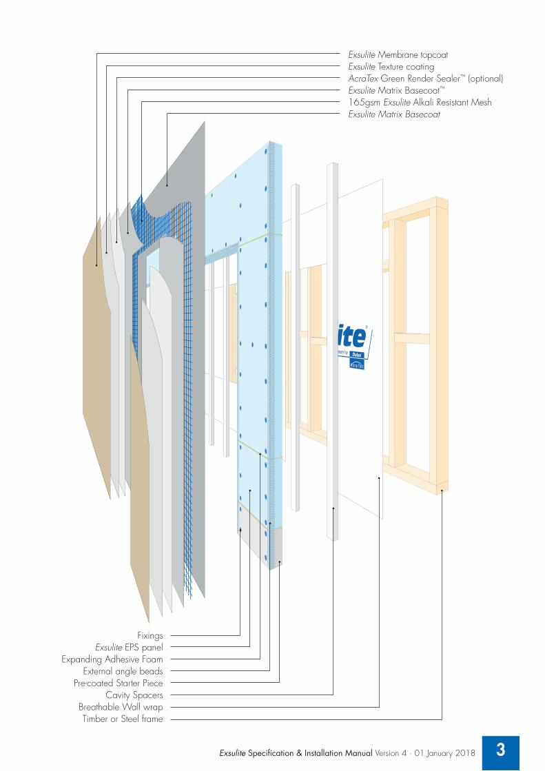
Exsulite Membrane topcoatExsulite Texture coatingAcraTex Green Render Sealer™ (optional)Exsulite Matrix Basecoat™
165gsm Exsulite Alkali Resistant MeshExsulite Matrix Basecoat
FixingsExsulite EPS panel
Expanding Adhesive FoamExternal angle beads
Pre-coated Starter PieceCavity Spacers
Breathable Wall wrapTimber or Steel frame
3Exsulite Specification & Installation Manual Version 4 · 01 January 2018

4
Section 1- Exsulite Facade System Specification
Light weight wall cladding solutions for specifiers, surveyors & builders This Specification & Installation Manual is designed to provide fixing guidelines to both timber and steel frame construction as a total integrated light weight, self draining, cavity walling system. This Technical Specification & Installation Manual is intended for use by Dulux AcraTex Exsulite Trained & Registered Installers, builders, specifiers and designers who are involved with the specification & installation of the Exsulite Facade System. Providing more design flexibility options and faster build process than conventional masonry construction.
1.1.0 OverviewDulux AcraTex - is a pioneer in the use of External Insulation Facade Systems (EIFS), designing and installing coating systems specifically for wall applications. EIFS walling systems have been used in Europe for over 50 years. In recent years the use of Lightweight Cladding Systems, as alternate solutions in the building and constructions industry has grown rapidly but proper system design and installation has not been considered.
The Building Code of Australia (BCA) (or National Construction Code (NCC)) requires appropriate design and installation controls to qualify any alternate solution and ultimate success requires a total system approach integrating design, componentry, installation and performance requirements.
The Exsulite Facade System by Dulux AcraTex protects specifiers, surveyors, builders and their clients from the risks of mixed componentry being used with uncontrolled installation. Exsulite Facade System by Dulux AcraTex offers a single supply source for the Total Light Weight Facade System – from wall wrap to the weatherproofing coating.
The Exsulite Facade System is a light weight exterior walling system that provides both weatherproofing & continuous insulation (CI) that is continuous across structural members rather than just between the framing members.
The Exsulite Facade System is designed as a total integrated non-load bearing lightweight facade system to deliver a weatherproof external building envelope with a self draining cavity for moisture management whilst providing high thermal performance (R value).
The Exsulite Facade System is CodeMark™ certified as a total integrated light weight facade system known as:
A) Exsulite Thermal Facade Cavity System – CodeMark CMA-CM40006
B) Exsulite Composite Thermal Facade Cavity System – CodeMark CMA-CM40057
The Exsulite Facade System comprises of an Exsulite breathable wall wrap, flashing tape to all openings & penetrations, Exsulite EPS Panel or Exsulite Pre-coated Composite Panel, Exsulite starter piece / cavity closer with weep holes, Exsulite fixing components, EPS “H” Grade wall cavity spacers where a cavity system is selected, Exsulite Matrix Basecoat™ with Exsulite alkali resistant mesh, Exsulite Texture and Exsulite Membrane weatherproof protective coating or an approved Dulux AcraTex texture and AcraTex membrane topcoat system designed & supplied by Dulux AcraTex and installed by a Dulux AcraTex Exsulite Trained & Registered Installer.
Variation and Modifications to the Exsulite Thermal Facade System Dulux AcraTex does not approve nor endorse the use of any non-standard or non-approved Dulux AcraTex Exsulite Thermal Facade System specification and or components. Dulux AcraTex will not be responsible for the performance of a system when installed outside the CodeMark accreditation and system limitations and when non-standard or non-approved components are used. The use of any non-standard or non-approved components will compromise the system and no product warranty will be issued for the system.

Exsulite Specification & Installation Manual Version 4 · 01 January 2018 5
1.1.1 If you are a Specifier: Dulux AcraTex ensures the Exsulite Facade System is fit for its specified purpose provided it is installed in strict accordance with the specification & installation manual and the agreed specification by a Dulux AcraTex Exsulite Trained & Registered Installer.
1.1.2 If you are a Dulux AcraTex Exsulite Trained & Registered Installer:Ensure you follow the design & installation guidelines provided in conjunction with the Exsulite Construction Drawing details. Exsulite system components can only be supplied by Dulux AcraTex or other Dulux AcraTex approved suppliers.
1.1.3 If you are a Builder: To ensure your build meets the design specification make sure all work is completed by a Dulux AcraTex Exsulite Trained & Registered Installer. An Exsulite “Certificate of Completion” & Project Warranty will only be issued when the installation is completed by a Dulux AcraTex Exsulite Trained & Registered Installer.
1.1.4 Design & Installation: Any alternative Exsulite Facade System project specific specification outside the standard system must be pre-sanctioned by Dulux AcraTex. The alternative Exsulite Facade System project specific specification must be secured prior to job commencement. Where an Exsulite Facade System project specific specification outside the standard approved system is used performance and/or appearance of the system may be compromised. As a consequence, any warranties or guarantees, whether express or implied may also be compromised.
Dulux AcraTex does not approve nor endorse the use of any non-standard or non-approved Dulux AcraTex Exsulite Facade System components. Dulux AcraTex will not be responsible for the performance of a system with non-standard or non-approved components. The use of any non-standard or non-approved components will compromise the system and no product warranty will be issued for the system.

6
1.2.0 Uses Exsulite Facade System by Dulux AcraTex provides a weatherproof cladding and insulation system for various Residential and Multi-Residential applications. It can also be installed to masonry & concrete substrates in accordance with a Dulux AcraTex project specific design fixing specification.
The Exsulite Facade System is used as a light weight integrated facade system as an alternative to masonry systems in the Multi-Residential and Residential Sector.
Residential External Walls to NCC Volume Two, Class 1 and 10 buildings with wind loads to either AS/NZS 1170.2 or AS 4055 “Wind loads for housing” for Wind Classifications N2,N3,N4, within the AS4055 limitations less than 8.5m in height less than 16m in width and where the length does not exceed five times the width and roof pitch does not exceed 35 degrees, fixed to either steel or timber frames.
Multi-Residential External Walls to NCC Volume One, Class 2 to 9 buildings with wind loads calculated in accordance with AS/NZS 1170.2. Fixed and finished to either steel or timber frame construction.
Integration of System Design, Components and Installation is delivered by a Dulux AcraTex Exsulite Trained & Registered Installer to ensure the build meets the design specification. System installation and job quality control documentation is project managed by a Dulux AcraTex Exsulite Trained & Registered Installer to ensure all jobs are installed in accordance with Exsulite Facade System specifications. The CodeMark Certificate of Conformity can be provided upon request.

Exsulite Specification & Installation Manual Version 4 · 01 January 2018 7
1.3.0 Design ConsiderationsCompliance: All design and construction must comply with the appropriate requirements of the current Building Code of Australia (BCA) regulations. The BCA is comprised of two volumes. The volumes divide the types of building into two groups being Volume 1: Class 2 to Class 9 Buildings and Volume 2: Class 1 & Class 10 Buildings – Housing Provisions. All the regulations for construction of buildings are contained in these volumes.
The Exsulite Facade System is CodeMark certified as a total integrated facade system in compliance with the Building Code of Australia's performance criteria for:
1. Structural Performance, Wind Resistance
2. Thermal Performance
3. Damp and Weatherproofing
CodeMark certification provides building certifiers with the confidence that the system performs against these criteria and together with an “Exsulite Certificate of Installation” from an Dulux AcraTex Exsulite Trained & Registered Installer confirms that the build meets the design specification at job completion.
Design details and construction methods need to comply to the NCC Building Code of Australia (BCA) regulations. During the design stage the BCA requirements are based on building type and should be considered to ensure conformance is achieved. The information provided in this manual should therefore be used as a guide only. It is then up to the relevant building surveyor / certifier to review the information as provided and to provide sign-off once satisfied that the building conforms to the relevant BCA criteria and specific job requirements. As part of the overall building approval process sign-off should be done prior to installation commencement or job start.
System design should consider factors such as:
• Class of building for Residential or Multi-Residential
• Location – coastal or inland
• Identify BCA performance requirements and any additional project specific needs
• Wind design actions subject to local wind pressures
• Self draining cavity to allow drainage of any moisture ingress or condensation
• Wall wrap – vapour permeable for condensation control & weatherproofing
• Thermal (R-Value) – energy efficiency
• Building Height
• Bush Fire Attack Levels (BAL)
• Acoustics (Rw Ctr values)
• Frame type, layout, design, stud spacing (steel or timber)
• Minimum panel thickness and fixing criteria based on wind design pressure and stud spacings
• Colour selection – Light Reflective Value (LRV>35)
• Additional wall insulation to improve energy efficiency
• Control joint installation
• Penetrations & External Fixings
• Building fire requirements in accordance with the National Construction Code (NCC) based on purpose of use to determine suitability

8
Benefits of Installing a Drainage Cavity System: The Drainage Cavity separates the Exsulite EPS Panel or Exsulite Composite Panel from the frame, creating a second layer of defence that allows air flow to dry out any condensation, moisture / water ingress that may form in the wall or behind the Exsulite EPS Panel or Exsulite Composite Panel as a second line of defence. The cavity is created by installing a vertical cavity spacer / batten to each wall stud. This allows any moisture / water ingress to drain down the back of the panel and out through the bottom of the wall via weep holes that are located within the cavity closer. Any remaining condensation or moisture within the cavity can then dry through ventilation provided along the bottom of the cavity and the Exsulite vapour permeable wall wrap.
A Drainage Cavity System will allow for moisture management as follows:A) Deflection: This first line of defence against moisture / water ingress. A well designed and constructed
Drainage Cavity system will deflect any potential water ingress or condensation away from the vapour permeable wall wrap and frame.
B) Drainage: A Drainage Cavity provides a second line of defence against condensation and or moisture / water ingress, allowing any build up behind the facade system to drain to the bottom of the wall section and out via the weep holes located in the cavity closer at the base of the wall.
C) Drying: A Drainage Cavity allows air flow through the bottom of the cavity so any remaining moisture or condensation can be absorbed by the vapour permeable wall wrap and allowed to dry out.
This drainage cavity is not ventilated to the outside air to an extent that would compromise the thermal performance of the systems.

Exsulite Specification & Installation Manual Version 4 · 01 January 2018 9
1.3.1 Design Ultimate Wind Pressures: A qualified engineer is to be involved to determine wind pressures based on a buildings geographic location in accordance with the Australian Standard AS4055 for residential housing or wind pressures determined from AS/NZS1170.2. Refer to the wind load tables on page 10 for recommended fixing requirements.
Design ultimate wind pressures must account for such factors as site wind speed, direction, terrain, height, shielding and topography. These project specific considerations should be conducted and approved by a qualified engineer at design stage prior to job commencement to ensure that the final system design is fit for purpose specific to the project and is designed to Australian Standards AS4055 or AS/NZS1170.2 for wind loading requirements. The wind load will determine the system specifications.
NCC Volume Two Class 1&10: Residential Housing ConstructionAS4055 has a more simplified method of determining wind loads for domestic housing and assists in determining the minimum panel thickness and fixings requirements. Design ultimate wind pressures, calculated in accordance with AS4055 “Wind loads for housing” wind classifications N2, N3, N4, N5 for wall framing of up to a 600mm maximum stud spacing for wall framing of up to a 600mm maximum stud spacing.
AS4055 limitations require buildings designed to this standard to be; less than 8.5m in height; less than 16m in width; where the length does not exceed five times the width; the roof pitch does not exceed 35 degrees. Exsulite Facade System shall be fixed to either steel or timber frames. Class 1 and 10 buildings that fall outside this scope require wind pressures to be calculated from AS1170.2 including regions of high pressures at corners.
General vertical fixing spacing is 275mm (5 fixings at 275mm spacings and 50mm edge distance top & bottom) for a 1200mm wide panel for most common applications in low wind suburban locations.
NCC Volume One Class 2 to 9: Multi-Residential Construction Where the Exsulite Facade System shall be fixed to either steel or timber frame buildings that fall outside AS4055, wind pressures are required to be calculated in accordance with AS1170.2 including regions of high pressures at corners. Fixing requirements will vary depending on wind pressure, frame design, and panel thickness. Refer to Table Three on page 10 for fixing specifications.

10
Table One – For Wind Classification to AS4055 Minimum Panel Thickness and Fixings
Wall Areas (Over 1200mm Away From Corners)
Wind Classification (AS4055)
Stud Centres 450mm Stud Centres 600mm
Min Panel Thickness
Fixings per stud
Fixing Spacings
Min Panel Thickness
Fixings per stud
Fixing Spacings
N2 60mm 5 275mm 60mm 5 275mm
N3 60mm 5 275mm 60mm 5 275mm
N4 60mm 5 275mm 75mm 5 275mm
Table Two – For Wind Classification to AS4055 Minimum Panel Thickness and Fixings
Walls Located Within 1200mm from Corners
Wind Classification (AS4055)
Stud Centres 450mm Stud Centres 600mm
Min Panel Thickness
Fixings per stud
Fixing Spacings
Min Panel Thickness
Fixings per stud
Fixing Spacings
N2 60mm 5 275mm 60mm 5 275mm
N3 60mm 5 275mm 75mm 6 220mm
N4 60mm 7 180mm 100mm 8 150mm
Table Three – AS1170.2 – Wind Pressure Criteria Design For Buildings That Fall Outside AS4055
Maximum fixing spacings to satisfy design ultimate wind pressures (kPa)
Design Ultimate Wind Pressure AS1170.2
Stud Centres 450mm Stud Centres 600mm
Min Panel Thickness
Min Fixings per stud
Fixing Spacings
Min Panel Thickness
Min Fixings per stud
Fixing Spacings
1.0 60mm 5 275mm 60mm 5 275mm
1.5 60mm 5 275mm 60mm 5 275mm
2.0 60mm 5 275mm 60mm 6 220mm
2.5 60mm 6 220mm 75mm 8 150mm
3.0 60mm 7 180mm 75mm 9 130mm
3.5 60mm 8 150mm 100mm 10 120mm
4.0 75mm 9 130mm 100mm 11 110mm
4.5 75mm 10 120mm - - -
5.0 75mm 11 110mm - - -
5.5 75mm 11 110mm - - -
Assumption is based on a panel size of 2500mm x 1200mm panel size. It is acceptable to use a panel thickness equal to or greater than the minimum requirement to satisfy the wind classification and meet thermal requirements. Increased peak pressures occur near the edges of side walls and corners on buildings. Using AS4055, the size of the building has been assumed and hence the size of these high pressure zones is specified as within 1200mm from wall corners.
NOTE: The fixings per stud indicate the number of fixings required at each stud along each sheet.

Exsulite Specification & Installation Manual Version 4 · 01 January 2018 11
1.3.2 Framing & Substructure:
Timber framing must comply with: AS 1684- National Timber Framing Code.
NOTE: The timber used in the project must be of sufficient standard in terms of durability to meet the local conditions to which the timber will be exposed, such as moisture or insect attack. The force applied to the panels by the wind loading is transferred into the stud frame. The frame must meet the requirements of the relevant Australian Standard. All bracing and hold down requirements should be met by the frame design. The allowance of shrinkage in timber framing in BCA 2006 Vol 2 Section 3.3.1.10 by providing gaps between frame and masonry should be adopted as a minimum.
1.3.3 Metal framing must comply with:AS 3623- Domestic Metal Framing - A cold-formed steel frame constructed in accordance with NASH Standard for Residential and Low-rise Steel Framing, Part 1: Design Criteria.
NOTE: Structural bracing is to be part of the integral wall frame. Exsulite Facade System doesn’t contribute to the structural integrity of the frame.
1.3.4 Slab & Footings: Slab and footings on which the building is situated must be designed and certified by a qualified structural engineer. This should comply in accordance with AS2870 “Residential Slabs & Footings” and / or AS 3600 Concrete Structures, as appropriate. Slab edge be in accordance with Australian Standard AS 2870-2011.
1.3.5 Ground Clearance & Pest Control:Install Exsulite Facade System with a minimum 75mm clearance (refer to Exsulite construction drawings for details) or in accordance with local building codes. Adjacent finished grade must slope away from the building in accordance with local building codes, typically a minimum slope of 50mm over the first metre. Termite management in accordance with AS 3660.1:2014 & AS 3660.3:2014. Refer to manufacturers specifications for installation method where required. Do not install external cladding in areas where it may remain in contact with standing water or debris. Do not back fill.
All BCA and local council requirements must be complied with by the builder of the project to ensure adequate protection against pest attack such as termites. The requirements vary across different states in Australia. Refer to the BCA code and AS 3660.1:2000.
1.3.6 Coastal Areas: In coastal areas located within 1km of the shoreline or large exposure to salt air, a protective weatherproof membrane topcoat must be used in all cases. Recommendation is that the facade should be regularly inspected for contamination & pollutants and washed down accordingly.
1.3.7 Colour Selection:Avoid the use of dark colours - these will raise the surface temperature and can damage the cladding system. Use only colours with a LRV greater than 35 or consult Dulux AcraTex on the potential to use InfraCOOL® Heat Reflective Coatings that can assist in keeping the surface cooler depending on your colour choice. Consult your Dulux AcraTex Representative for project specific requirements.

12
1.3.8 Control Joints:During the life of a building, the building and materials that it is constructed from will move. This movement is due to many factors such as structure movement, thermal expansion & contraction and differential movement between materials. This movement, unless relieved or accommodated for will impart stress on the building and construction materials and lead to cracking. To accommodate for building movement, to relieve stresses and reduce the risk of cracking, movement joints must be installed.
Articulation Joints (A.J.) make the walls more flexible by breaking it into a serious of small areas. Differential movement between the facade and adjacent structural elements need to be accommodated for via an (A.J.) joint.
Control Joints (C.J.) is an expansion joint to relieve thermal expansion or contraction between the Exsulite Facade System and other adjacent building substrate or structures. Good building practice provides for expansion joints at 3m (max) height & 6m (max) wide intervals and at all building weak points or where potential cracking may occur e.g. in line with openings (windows / doors), horizontally between floor levels and at all interfaces of different building construction materials and / or as defined by a responsible Building / Project Engineer. The placement and correct installation of control joints is the responsibility of the Building Engineer / Builder in determining the placement and number of control joints to accommodate any anticipated movement. Typical vertical control joints and horizontal joints filled with a suitable backing rod and approved flexible polyurethane sealant. The project engineer has responsibility for determining where control joins are to be located.
1.3.9 Fire Resistant Levels (FRL) & Bush Fire Attack Levels (BAL):BCA Vol 2 (Part 3.7.1) details the requirements in residential buildings for fire resistance for external walls where the external wall is less than 0.9m from an allotment boundary or less than 1.8m from a building on the same allotment. In these circumstances a FRL is required from the outside of not less than 60/60/60.
The Exsulite Facade System has not been tested and is not suitable for use as a FRL rated compliant system for boundary walls and/or party walls as a standalone walling system. Where a FRL level / rating is required for such installation an independent appraisal and approval is needed by a qualified fire engineer.
Bushfire Attack Levels (BAL):The Exsulite System has been tested for heat intensity and ember attack of bushfires in relation to AS 3959-2009 Construction of Buildings in Bushfire prone areas. Exsulite Facade System has passed AS 1530.8.1:2007 and is approved for use in bushfire prone areas up to BAL 29.
NOTE: The Exsulite Facade System can be used in a BAL 29 region when installed with a Exsulite Pre-coated Starter Piece and/or Exsulite Starter Channel with weep holes in accordance with Exsulite Installation & Construction Drawing Manuals and Exova Test Certificates.
AS3959-2009 for construction in a bush-fire prone areas specifies all joints in the external surface material of walls shall be covered sealed, to prevent gaps no greater than 3mm.
1.3.10 Exsulite Exposure to Heat Sources:The Exsulite finished surface should not be continuously exposed to temperatures in excess of 80˚C due to the risk of damage from softening and shrinkage. Particular care must be taken when installing and operating heat producing appliances e.g. Barbeques, Patio Heaters, Hot Water Services, Heating Units and Air Conditioners to ensure Exsulite surfaces do not become damaged by the heat generated by these items.
All heat producing appliances should be installed in accordance with the manufacturer's instructions and comply with the relevant building regulations and Australian Standards e.g. AS/NZS5601, AS/NZS3500.4 and AS3000. Their exhaust vents and flues must be directed away from Exsulite finished surfaces to avoid excessive heating.
It is highly recommended that equipment capable of generating high levels of radiant heat such as Barbeques, Patio Heaters etc., should not be operated closer than 1.5 metres from any Exsulite finished surface.

Exsulite Specification & Installation Manual Version 4 · 01 January 2018 13
1.4.0 System Performance Criteria The Exsulite Facade System is a fully integrated system designed & supplied by Dulux AcraTex and installed by a Dulux AcraTex Exsulite Trained & Registered Installer in accordance with this Exsulite Facade System Specification and Installation Manual, Construction Drawings and in conjunction individual product and application data sheets to all building code and Australian standard requirements.
The Exsulite Facade System is designed as a total integrated non-load bearing lightweight facade system to deliver a weatherproof external building envelope, with a self draining cavity for moisture management whilst providing excellent thermal performance (R value).
The Exsulite Facade System is CodeMark certified as a total integrated light weight facade system known as:
A) Exsulite Thermal Facade Cavity System – CodeMark CMA-CM40006
B) Exsulite Composite Thermal Facade Cavity System – CodeMark CMA-CM40057
Exsulite Facade System(s) comprise of Exsulite breathable wall wrap, flashing tape to all openings & penetrations, Exsulite EPS Panel or Exsulite Pre-coated Composite Panel, Exsulite starter pieces / cavity closer with weep holes, Exsulite fixing components, EPS “H” Grade wall cavity spacers where a cavity system is selected, Exsulite Matrix Basecoat with Exsulite alkali resistant mesh, Exsulite Texture and Exsulite Membrane weatherproof protective coating or a Dulux AcraTex Texture and AcraTex Membrane top coat system, designed & supplied by Dulux AcraTex and installed by a Dulux AcraTex Exsulite Trained & Registered Installer.
Unless otherwise specified or approved, all Exsulite Facade System components & coating materials used must be Dulux AcraTex / Exsulite products as listed below. All system components & coating products are to be delivered to the job in unbroken containers bearing the brand name and name of the manufacturer and must be subject to the installers inspection & confirmation of correct materials received in good order.

14
1.4.1 Exsulite Facade System consists of: • Exsulite Breathable-Vapour Permeable Wall Wrap
• Cavity Spacer: “H” Grade EPS Batten
• Damp proof course
• Exsulite EPS Panel or Exsulite Composite Panel
• Exsulite fixing disk & Class 3, 10 gauge bugle head screws (further than 1km of coastal areas)
• Exsulite Starter Channel with weep holes - placed at the base of the cavity, these function as a cavity closer to drain to the exterior at the bottom of the cavity
• Exsulite Starter Piece
• Corner angles and expansion beads installed prior to render application
• Self-adhesive flashing tape for weatherproofing around all window frames including sills, doors, openings, penetrations, intersections, connections, heads and jambs - all of which must be flashed prior to panel installation
• Dulux AcraTex Approved adhesive expanding foam
• Exsulite Matrix levelling coat with a minimum 165gsm Exsulite alkali resistant mesh
• Exsulite Acrylic Texture coating to selected colour with a LRV>35
• Selleys® Flexiseal Joint Sealant or as approved by Dulux AcraTex
• Exsulite Membrane or Dulux AcraTex AcraShield® Advance or AcraSkin™ weatherproof membrane top coat to selected colour with a LRV>35
1.4.2 Moisture Management – Cavity System: The Exsulite Facade System helps moisture management through its self draining cavity spacer & non-reflective Exsulite breathable water barrier wall wrap. If condensation occurs, moisture can efficiently drain from the cavity through the specially designed starter channels with weep holes that also provide airflow throughout the entire cavity.
Panels are fixed to the vertical cavity spacer (EPS “H” Grade battens) and the cavity drains vertically to the bottom starter channel with weep holes. The cavity spacers (battens / top hats) separate the cladding material from the timber framing. It protects the frame from any moisture / water ingress and condensation by providing a gap allowing moisture to drain down the outside face of the wall wrap & cladding and out through the base of the cavity. Any remaining moisture within the cavity is able to dry due to the ventilation provided along the bottom of the cavity closer (starter channel with weep holes).

Exsulite Specification & Installation Manual Version 4 · 01 January 2018 15
1.4.3 Exsulite Facade System Composition: Exsulite EPS panel and Composite Panel inner EPS layer is manufactured to AS1366 Part 3 ~ 1992. The Exsulite EPS panel and Composite Panel inner EPS layer is produced from expanded polystyrene (EPS) which is a lightweight product displaying self insulative properties that can enhance the energy efficiency of a building. The Exsulite EPS panel and Composite Panel can be used in Class 1 and 10 building applications and can be fixed to steel, timber and masonry.
Toxicity of Exsulite EPS and Composite Panels decomposition products of EPS appears to be no greater than for wood and decidedly less than other conventional building products. Since it has no food value, Exsulite EPS and Composite Panels do not attract ants, termites, or rodents. However, it is not a barrier to them. Ants, termites and rodents may chew through EPS Foam to reach food or establish a comfortable home.
Expanded polystyrene products are combustible and should not be exposed to open flame or other ignition sources. Insulation material, as with other organic material, must be considered combustible and constitute a fire hazard if improperly used or installed.
Material Ignitability Index (0-20)
Spread of Flame Index (0-10)
Heat Evolved Index (0-10)
Smoke Produced Index (0-10)
Expanded Polystyrene – EPS 12 0 3 5
Sizes; Exsulite EPS Panel – 2500mm x 1200mm
Exsulite Composite Panel – 2400mm x 1200mm
Standard Thickness: 60mm, 75mm and 100mm
Physical Property Unit M Grade H GradeTest method
used to measure compliance
Average Density kg/cum 19 24
Compressive strength at 10% deformation (min). kPa 105 135 AS2498.3
Cross breaking strength (min). kPa 200 260 AS2498.4

16
Exsulite Facade System Performance – R Value PerformanceSmart rate assessment* as a total walling system from plasterboard to coating.
Exsulite Thermal Facade Cavity System
Panel Thickness† Cavity Spacer Wall Insulation R Value With Insulation
R Value No Insulation
60mm 15mm R2.0 3.945 2.105
75mm 25mm R2.0 4.337 2.497
100mm 25mm R2.0 4.990 3.130
The above calculations are in presented in accordance with the principles outlined in the Building Code of Australia (2012). Exsulite R-Values are calculated on M Grade EPS to Australian Standard 1366.3 with a conductivity value of 0.0383 W/m2.K.
*Smart Rate Thermal Assessment report can be provided upon request

Exsulite Specification & Installation Manual Version 4 · 01 January 2018 17
1.4.4 Impact Resistance: The Exsulite Thermal Facade System provides impact resistance to levels similar to that of other common non-masonry materials. Minor damage can be repaired by recoating with Dulux AcraTex coating system. Where additional impact resistant is required Dulux AcraTex recommend an additional layer of Exsulite Matrix Basecoat with Exsulite Mesh – Refer to Exsulite Finishing System Application
1.4.5 Water Vapour Resistance:Exsulite EPS Panels have one of the highest resistance levels of all materials used for insulation. Exsulite EPS Panels have a low water vapour transmission rate, however it is not considered as an adequate vapour barrier. Exsulite Breathable Vapour barrier Wall Wrap must be installed in all cases irrespective of the buildings environment and location as part of the full Exsulite Facade System.
1.4.6 Weatherproofing & Water Resistance:Exsulite Facade System – weatherproof finishing Exsulite Membrane, AcraTex AcraShield and AcraSkin top coats by Dulux AcraTex has been tested to AS4548.5-1999 Guide to Long Life Coatings for Concrete & Masonry. Testing shows water transmission results of <1g/m2 / 24hr / kPa and a vapour transmission rate of 51.9g/m2 / 24hr. (Refer to Dulux AcraTex product data sheets).
Exsulite Facade System weatherproofing performance complies with the requirements of NCC-2016 Weatherproof Verification Methods V2.2.1 & F.V.1
1.4.7 Penetrations:Normal industry standards should be followed for the installation of services into the building. In order to avoid disrupting the layout, services should be installed through the frame. All penetrations through the Exsulite Facade System must allow for differential movement between the installed system and the services.
All penetrations are a potential source of water ingress and spread of fire and are required to be sealed with a Dulux AcraTex or head contractor approved PU paintable flexible sealant. Back blocking should occur for items such as downpipe brackets, outside taps, light fittings and other building services to the appropriate locations and apply flashing tape before panel installation.
1.4.8 Waste Management:Exsulite EPS Panel is a lightweight material that is easily dispersed in windy conditions. All waste and cut offs should be stored in plastic bags, secured and disposed of in accordance with local regulations. Good frame design will minimise the amount of waste generated during the construction process.

18
Section 2 – Exsulite Facade System Installation
2.1.0 Dulux AcraTex Exsulite Trained & Registered Installer The Building Code Australia (BCA) requires appropriate design and installation controls to qualify any alternate solution and ultimate success requires a total system approach integrating Design, Componentry & Installation.
Using a Dulux AcraTex Exsulite Trained & Registered Installer not only provides peace of mind but also ensures that the final build meets the design specification. All Dulux AcraTex Exsulite Trained & Registered Installer accreditation can be verified by their Exsulite Identification Card and Registration Number. Project QA Process is a critical element of the Exsulite total system approach and the Dulux AcraTex Exsulite Trained & Registered Installer network ensures total facade system compliance - from start to finish.
NOTE: Design & installation of any non-standard or non-approved Dulux AcraTex Exsulite Facade System components will not be the responsibility of Dulux AcraTex and will be a Non Conforming System and void any product warranty or claims in relation to product / system performance.
2.1.1 Quality Control: Dulux AcraTex Exsulite Trained & Registered Installers are required to participate in on-going refresher training from Dulux AcraTex to maintain their installer accreditation and only a Dulux AcraTex Exsulite Trained & Registered Installer can provide an “Exsulite Certificate of Installation” for job sign-off.
2.1.2 Handling and Storage: Exsulite Facade System panels and fixing components should be stored elevated, under cover and laid flat. Edges and corners are to be protected at all times. Dulux AcraTex recommends that the specified Dulux finishing system be applied to the panels as soon as possible according to this specification. UV rays don’t have an adverse effect on the performance of the EPS or Composite Panels during typical construction timeframes however, if installation is interrupted for any extended periods of time with the possibility of inclement weather, the surface of all panels should be covered in order to provide them with protection. If the panels are exposed to inclement weather they will need to dry prior to any coating being applied. Any panels exposed to an extended period of inclement weather should be replaced prior to installation.
2.1.3 Component Checking: Damaged EPS or Composite Panels or panels that have been in contact with harsh solvents or acids should not be used. EPS or Composite Panels should be stored inside a building where possible. Where outside storage cannot be avoided, the panels should be stacked elevated from the ground and covered with a polythene sheet or weatherproof tarpaulin.
It is the responsibility of the Dulux AcraTex Exsulite Trained & Registered Installer to conduct a stringent quality check of all the Exsulite components prior to commencement of work to ensure the correct product items, quantities and colours have been delivered to site in good order and are ready for use.
Dulux AcraTex will not be responsible for rectifying potential claims where no evidence of the above following installation and job completion is provided.

Exsulite Specification & Installation Manual Version 4 · 01 January 2018 19
2.1.4 Exsulite Facade System Components:
Product Description Product Description
Exsulite Breathable-Vapor Permeable Wall Wrap
External AnglesExpansion Joint Trim
Corner angles and expansion beads installed prior to render application.
Cavity Spacer: “H” Grade EPS Batten where a cavity is to be installed
Flashing Tape; aluminium bituminous self-adhesive flashing tape for weatherproofing around all window frames including sills, doors, openings, penetrations, intersections, connections, heads and jambs - all of which must be flashed prior to panel installation
Damp Proof CourseDulux AcraTex approved PU expanding foam adhesive
Exsulite EPS Raw Panel
Alkali Resistant Mesh
Exsulite Matrix levelling coat with 165gsm Exsulite alkali resistant mesh
Exsulite Composite Panel
Exsulite Composite Pre-coated Panel
Acrylic Texture
Exsulite or Dulux AcraTex Acrylic Texture coating to selected colour with a LRV>35
Class 3 Screw
Exsulite Fixing Disk & Class 3, 10 Gauge Bugle Head Screws (further than 1km of coastal areas)
Selleys® Flexiseal Joint Sealant or as approved by Dulux AcraTex
Starter Channel
Exsulite Starter Channel with weep holes. Placed at the base of the cavity, these function as a cavity closer to drain to the exterior at the bottom of the cavity.
Membrane
Exsulite Membrane or Dulux AcraTex AcraShield Advance or AcraSkin weatherproof membrane top coat to selected colour with a LRV>35
Exsulite Pre-coated Angled Cavity Starter Piece (SP1)
Exsulite Pre-coated Sill Piece (SP4)
Exsulite Pre-coated Reveal & Slab Cavity Starter Piece (SP2)
Exsulite Pre-coated Square Cavity Starter Piece (SP3)

20
2.1.5 Exsulite Facade System - Material Estimate Guide:
Exsulite EPS Panel size (2500mm x 1200mm) = 3m2
Exsulite Composite Panel (2400mm x 1200mm) = 2.88m2
Exsulite Cavity Spacer; "H" Grade EPS Spacer (15mm, 20mm, 25mm thick and 1.2m long)
Job size (m2) of wall area to be installed
Calculate total wall area including openings = total m2
Calculate all openings (doors & windows) = total m2
Take total wall area (m2) minus all openings (m2) = total (m2) area to be installed
Take (m2) of area to be installed plus 10% and Divide by “3” to give you the number of Exsulite EPS panels required OR Divide by 2.88 to give you the number of Exsulite Composite Panels required
Exsulite Facade System Screws & Disks - Allow minimum 9 of each per m2 or 25 of each per Exsulite Panel
Exsulite EPS Panel or Composite Panel & Screws (10G Class 3) - Cavity System sizes:
• 105mm screws for 60mm panel with 15mm Cavity Spacer (minimum)
• 130mm screws for 75mm panel with 25mm Cavity Spacer (minimum)
• 150mm screws for 100mm panel with 25mm Cavity Spacer (minimum)
NOTE: Minimum penetration into timber frame is 30mm
Exsulite Breathable Wall Wrap - Size 2.7m x 30m = 82m2
Exsulite Starter Starter Piece: Size 2400mm long = measure lineal metres to where they are to be installed
Damp Course - Size: 300mm x 30m
Foam Adhesive = 1 x 750ml per 30m2 (approximate only)
Flashing Tape for openings - size: 25m roll
Selleys Liquid Nails® Fast - size: 300ml allow 1 tube per 12 lineal metres of angles (approximate)
Primer Coat - Dulux AcraTex Green Render Sealer (optional)
Selleys Flexi Seal Sealant: size: 600ml
Base Coat - Exsulite Matrix: Size 20kg = Approximately 3m2 @ 4mm thick plus wastage
165gsm Exsulite Alkali Resistant Mesh: Size 50m x 1m = 50m2
Texture Coat - Exsulite Texture: Size 15L = Approximately 12m2
Protective Membrane Topcoat - Exsulite Membrane: Size 15L = Approximately 70m2
NOTE: The above calculations are a guide only. For project specific requirements please talk to your Dulux AcraTex representative.

Exsulite Specification & Installation Manual Version 4 · 01 January 2018 21
Material estimate guide for typical job lot based as follows:
Estimate is based on a Exsulite EPS 75mm Panel and 25mm Exsulite Cavity Spacer
ProductsMetres Squared (wall surface)
60 80 100 120 140 180
Quantity Required
75mm EPS - 2500 x 1200 x 75mm 20 27 34 40 47 60
Battens H Grade (PK100) - 1200 x 40 x 25 2 2 3 3 4 4
10 Gauge Square Drive (Timber) - 130mm Class 3 Galv (PK500) 2 2 2 3 3 5
Exsulite Washers - 40mm Diameter (PK500) 2 2 2 3 3 5
Breathable Wall Wrap (Watergate) - 2740 x 30m roll = (82m2) 1 2 2 2 2 3
Alkali Mesh - 1m x 50m - 5 x 5mm = (50m2) 2 2 2 3 3 4
EPS Starter 2500 x 300 x 75mm 10 14 16 20 23 26
Expansion Joint PVC Trim - 3m x 3.5mm 3 4 5 6 7 9
Flashing tape - 75mm x 25m roll 2 3 3 4 5 5
Selleys Liquid Nails Fast - 300ml Tube 6 8 10 12 14 18
Foam Adhesive - 750ml Canister 4 6 7 6 8 12
Application Gun - Metal 1 1 1 1 1 1
Gun Cleaner - 300ml Canister 1 1 1 2 2 2
NOTE: The above calculations are a guide only. For project specific requirements please talk to your Dulux AcraTex representative.

22
2.1.6 Tools Requirements:
Electric Saw with dust exraction unitElectric saw
with diamond tip blade, fitted with a vacuum extraction appliance
where possible
Safety Gloves
Safety Glasses
Safety gloves & safety glasses Hammer
HammerFoam Float
Plastic FloatFloats – plastic & foam
Hot Knife
Hot Knife
Dust Mask
Dust mask Hawk & Trowel
Hawk & Trowel
Hawk & trowelEmpty Pail Empty Pail
Empty PailEmpty pails
Hand Saw
Hand saw Spirit Level Spirit level Mixing DrillMixing drill
Drill
Cordless drill
Portable Work BenchPortable work benchStaple Gun
Staple GunRoller
RollerScaffolding
Scaffold
Knife
Sharp blade knife Caulking GunCaulking gunSpatula
SpatulaTape Measure
Tape Measure

Exsulite Specification & Installation Manual Version 4 · 01 January 2018 23
2.1.7 Before Commencing Installation:Read the Exsulite Facade System Specification & Installation Manual in conjunction with the project consultant, project specific specification and drawing details to familiarise yourself with the relevant project specific requirements.
The Exsulite Facade System does not contribute to the structural integrity of the frame. All studs and noggings must be checked with a long straight edge for line and face accuracy to ensure the stud wall has a true and accurate outside face, wall frames are defective if they deviate in horizontal or vertical by more than 4mm in any 2M length wall in accordance with the VBA 2015 Guide to Standard Tolerance. The panel will not straighten any warped or defective frames and any warping may be visible at job completion.
It is the responsibility of the Dulux AcraTex Exsulite Trained & Registered Installer to ensure that the substrate / framework to which the Exsulite Facade System is to be installed to is properly prepared in strict accordance with the relevant Australian Standards, Building Code of Australia regulations and project specific requirements.
Ensure that all preparation work prior to commencement of system installation has been completed by the relevant trades and that the substrate onto which the Exsulite Facade System is to be fixed to is ready for installation work to commence. This includes installation of flashings to brickwork, window & door openings and penetrations. Ensure wall levels have been checked & signed off by project / site supervisor. Where the installer is not satisfied with the substrate standard they are to advise the head contractor prior to commencement of work of these concerns. Once the substrate has been rectified to a standard that meets the site agreed sample work, only then can the work commence.
Pre Job Check should include but be limited to:
• Check that the frame conforms to the relevant BCA regulations and Australian Standards as well as local standards for structural requirements including wind loadings and bracing. Refer to the relevant Exsulite wind design criteria for panel & fixing based on project specific wind pressures.
• Check with plumbers and electricians and back-block for any wall mounted services as it is imperative that this is done prior to panel installation.
• Check that all eaves and flashings have been completed by the builder to the requirements of the project specification prior to commencement.
• Check that the wall wrap installed by the builder is of breathable type, and if not, advise the builder that the wrap does not conform and will be required to be replaced with Exsulite wall wrap.
• Check that correct windows with reveal sizes are fitted in accordance with the project specification. Check that the outside of the reveal is flush with the external frame and 10mm proud on the inside allowing for the internal plasterboard. Make sure that they have been fixed off correctly, level and plumb.
• Check to ensure that the correct damp course has been installed to slab edge and termite treatment has been completed. Where no damp course has been installed by others then it must be installed by the Dulux AcraTex Exsulite Trained & Registered Installer prior to the Exsulite wall wrap being installed.
2.1.8 Timber framing must comply with AS1684 – National Timber Framing Code:The Exsulite Facade System can be fixed to either timber of steel framing. All frames should comply with the relevant building code and / or Australia Standard for the type of construction. Studs should be positioned to a maximum of 600mm centres with noggings at maximum of 1350mm centres. The frame must be constructed correctly to allow the fitting of the panels so that a true and accurate outside face is achieved. If the frame is out of tolerance it should be checked and straightened prior to installation commencing.

24
2.1.9 Structural bracing is to be part of the integral wall frame: The Exsulite Facade System does not contribute to the structural integrity of the frame. All studs and noggings must be checked with a long straight edge for line and face accuracy to ensure the stud wall has a true and accurate outside face, wall frames are defective if they deviate in horizontal or vertical by more than 4mm in any 2M length wall in accordance with the VBA 2015 Guide to Standard Tolerance.
NOTE: The panel will not straighten any warped or defective frames and any warping may be visible at job completion.
2.1.10 Metal framing must comply with: AS3623- Domestic Metal Framing - A cold-formed steel frame constructed in accordance with NASH Standard for Residential and Low-rise Steel Framing, Part 1: Design Criteria.
2.1.11 Window Reveals Details:
Exsulite EPS Panel Exsulite Composite Panel Exsulite Cavity Spacer Window Reveal
75mm 25mm 65mm
100mm 25mm 90mm
Be sure that the window reveals are sitting 25mm proud of the studs.
2.1.12 Placement of Expansion Joints:Good building practice provides for expansion joints at 3m (max) height & 6m (max) wide intervals and at all building weak points or where potential cracking may occur e.g. in line with openings (windows / doors), horizontally between floor levels and at all interfaces of different building construction materials and / or as defined by a responsible Building / Project Engineer. The placement and correct installation of control joints is the responsibility of the Building Engineer / Builder to determine if the joints are sufficient to accommodate the movement of the specific project building. Typical vertical control joints are 10mm-12mm wide and horizontal joints are 15mm-20mm wide and filled with an approved paintable flexible sealant.
Alternatively a U-PVC control joint bead is inserted in position prior to render application. After the texture coat application, the bead is cut through and filled with Selleys Flexiseal. (Refer to the Selleys specification data sheet).
Placement of Expansion / Control Joints Maximum Distance
Horizontal Wall Areas: Wall length 6 Metres 6 Metres
Vertically: Construction joints between floor levels and gable ends, where the total wall height including gable exceeds maximum distance
3 Metres
Scribed control joints: Above large window and door openings
Note Internal Corner: When rendering, mesh up to but not across corner then later ‘scribe’ a control joint into the render, cutting (nick) the mesh intermittently to relieve the tension within the mesh. Fill with sealant prior to texture coating

Exsulite Specification & Installation Manual Version 4 · 01 January 2018 25
2.1.13 Fixing Guide:
Exsulite Thermal Facade Cavity System – Residential Housing Vol 2 Class 1 & 10
Frame Type
Panel Thickness*
Cavity Spacer
Exsulite EPS Starter Piece
Thickness
Minimum Screw Length Class Gauge Type
Timber
60mm 15mm 60mm 105mm 3 10 Bugle Needle Point
75mm 25mm 75mm 130mm 3 10 Bugle Needle Point
100mm 25mm 100mm 150mm 3 10 Bugle Needle Point
Metal
60mm 15mm 60mm 105mm 3 10 Bugle Needle Point for use up to 0.55mm steel
75mm 25mm 75mm 130mm 3 10 Bugle Needle Point for use up to 0.55mm steel
100mm 25mm 100mm 150mm 3 10 Bugle Needle Point for use up to 0.55mm steel
*60mm panel for fixing at 450mm centres only.
NOTE: Within 1km of a coastal environment Class 4 screws must be used. This is deemed as medium to severe marine exposure in accordance with AS 3566.
Exsulite fixings Class 3 (non coastal areas) 10 Gauge screws with an Exsulite 40mm fixing disk is driven into the middle of the stud until the disk just penetrates the panel face. When fastened correctly, the screw head and the 40mm fixing disk should be slightly countersunk in a concave recess on the outer surface of the panel and located so as it retains its original shape.
NOTE: Care should be taken to not overdrive the fixing as this will strip the plastic disc and the fixing will be ineffective.
General fixing maximum spacings of 275mm (5 fixings at 275mm spacing / 25 per sheet and within 50mm from panel edges with a minimum 30mm penetration into timber frame for a 1200mm panel width) with stud spacings at 600mm maximum and subject panel span and thickness subject to wind pressures, stud spacings and system specification. Refer to page 10 for further details before commencing job.

26
2.2.0 Installation Procedure
System is to be installed to a properly prepared substrate (frame) in strict accordance with the relevant Australian Standards, Building Code of Australia regulations, and project specific requirements. Ensure that all preparation works prior to commencement of system installation have been completed by the relevant trades and that the substrate onto which the Exsulite Facade System is to be fixed to is ready for installation works to commence.
Where the installer is not satisfied with the substrate standard they are to advise the head contractor or builder prior to commencement of works of these concerns, once the substrate has been rectified to a standard that meets the site agreed sample works, only then can the works commence.
Note: Exsulite Facade System does not contribute to the structural integrity of the frame.
2.2.1 Exsulite Wall Wrap:Install the Exsulite Breathable Wall Wrap with a staple gun to a properly prepared frame. Appropriate head flashings over the top of the building wrap must be fitted before a compatible building wrap tape is used to seal the junction of the head flashing and building wrap. If head flashings cannot be used, an acceptable alternative flashing must be provided.
NOTE: Wall wrap is to have neither tears nor break points.
Followed by installation of the Exsulite Cavity Spacer where a Exsulite cavity system is specified and installed, fixed to each stud.
2.2.2 Weatherproof Flashing Tape:Install Dulux AcraTex approved and supplied Flashing Tape; self-adhesive flashing tape for weatherproofing around all windows frames including sills, doors, openings, penetrations, intersections, connections, heads & jambs and must be flashed prior to panel installation. It must cover both wall wrap and substrate to ensure a closed weatherproof seal is achieved.
2.2.3 Cavity Spacer:Vertically install “H” Grade Cavity Spacer to each stud for residential housing construction, Fix the cavity spacer onto all studs and around all windows & doors and to the top edge of roof flashing.
2.2.4 Exsulite Starter Channel with Weep Holes:The starter channel must be installed 10mm above metal flashings, roof surface and 10mm above the slab edge and butt joined and sealed on the junction with an approved PU sealant or similar to avoid separation. Apply Selleys Liquid Nails Fast Grab or Dulux approved spray foam adhesive to the inside base of the starter channel prior to installing the Exsulite panel to assist with adhesion of the panel to the starter channel. Once tacked into position, the screwing of the Exsulite panels will secure the starter channel into its finishing position at the bottom.
NOTE: Refer to the Exsulite Construction Drawings for “over roof or slab edge” details.
When installing the Exsulite starter channel and/or Exsulite Starter Piece above a deck, flat or pitched roof, ensure a gap is left between the bottom of the Exsulite starter channel and Starter Piece and the finished level.
NOTE: Refer to the Exsulite Construction Drawings for further details.

Exsulite Specification & Installation Manual Version 4 · 01 January 2018 27
2.2.5A Over Pitch Roof Set Out – Exsulite Angled Starter Piece (SP1)The Exsulite Angled Starter Piece (SP1) is to be installed horizontally above roof section and fixed to each stud 50mm & 150mm from top edge.
NOTE: Ensure fixings do not penetrate into metal flashing and ensure that the flat or pitched roof has had the correct flashing installed by others which is fit for purpose and is sloping away from the wall cladding
When installing the Exsulite Angled Starter Piece (SP1) channel above a deck, flat or pitched roof, ensure a gap of is left between the bottom of the Exsulite Angled Starter Piece (SP1) and the finished level.
1 2
A
B
1. Install Exsulite Cavity Spacers with galvanised clouts on all studs to top edge of roof flashing.
2. Determine height of Exsulite Angled Cavity Starter Piece (SP1).
A) The gap between the bottom of the starter piece and the top of a tiled or metal roof is 10mm from the roof surface to conform to the requirements of NCC-2016 Weatherproof Verification Methods V2.2.1 and F.V.1.
B) Building wrap must terminate 20mm above 3mm gap. A gap no greater than 3mm (max.) between back of panel and metal roof flashing to conform to AS3959-2009 for construction in bush-fire prone areas.
NOTE: Refer to Exsulite Construction Drawings EXS804A and EXS805A for clarity.
2.2.5B Over Pitch Roof Set Out – Exsulite Angled Aluminium Starter Channel An Aluminium Angled Starter Channel with weep holes can also be used; installed at 10mm above roof surface where the following EPS Panel and Cavity Spacer configuration are specified:
• 15mm Cavity Spacer with 60mm EPS Panel
• 25mm Cavity Spacer with 75mm EPS Panel
• 25mm Cavity Spacer with 100mm EPS Panel
NOTE: Refer to Exsulite Construction Drawings EXS806 and EXS807 for clarity.

28
2.2.6 Bulkhead / Balcony Set out – Exsulite Square Cavity Starter Piece (SP3)
NOTE: Refer to Exsulite Construction Drawings EXS751 for clarity.
1. Mitre cut left side at 45 degrees external corner of Exsulite Square Cavity Starter Pieces (SP3).
2. Mitre cut right side at 45 degrees external corner of Exsulite Square Cavity Starter Pieces (SP3).
3. Confirm drip edge depth specified. Determine height of Exsulite Square Cavity Starter Piece (SP3). A) Flick chalk line across cavity spacers from corner to corner.
4. & 5. Completed bulk with drip line.
1 2 3
54
A
Exsulite Specification & Installation Manual Version 4 · 01 January 2018 29
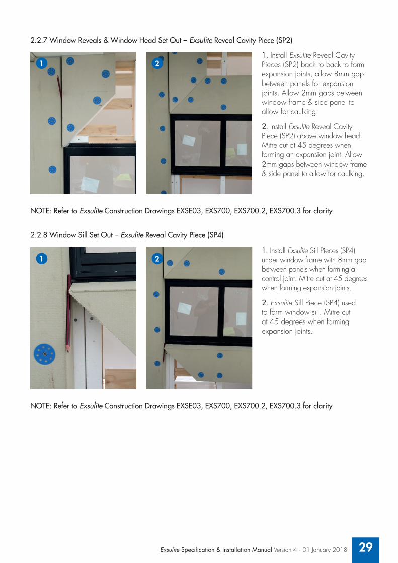
2.2.7 Window Reveals & Window Head Set Out – Exsulite Reveal Cavity Piece (SP2)
NOTE: Refer to Exsulite Construction Drawings EXSE03, EXS700, EXS700.2, EXS700.3 for clarity.
2.2.8 Window Sill Set Out – Exsulite Reveal Cavity Piece (SP4)
NOTE: Refer to Exsulite Construction Drawings EXSE03, EXS700, EXS700.2, EXS700.3 for clarity.
1. Install Exsulite Reveal Cavity Pieces (SP2) back to back to form expansion joints, allow 8mm gap between panels for expansion joints. Allow 2mm gaps between window frame & side panel to allow for caulking.
2. Install Exsulite Reveal Cavity Piece (SP2) above window head. Mitre cut at 45 degrees when forming an expansion joint. Allow 2mm gaps between window frame & side panel to allow for caulking.
1. Install Exsulite Sill Pieces (SP4) under window frame with 8mm gap between panels when forming a control joint. Mitre cut at 45 degrees when forming expansion joints.
2. Exsulite Sill Piece (SP4) used to form window sill. Mitre cut at 45 degrees when forming expansion joints.
1
1
2
2
30
2.2.9 Exsulite Window Opening With Control Joints Set Out
NOTE: Refer to Exsulite Construction Drawings EXSE03 for clarity.
2.2.10A Slab Rebate Set Out – Exsulite Slab Cavity Starter Piece (SP1 or SP3)
NOTE: Refer to Exsulite Construction Drawings EXSE01 and EXS101B for clarity.
2.2.10B Slab Rebate Set Out – Exsulite Starter Channel with Weep HolesThe starter channel must be installed 10mm above metal flashings, roof surface and 10mm above the slab edge and butt joined and sealed on the junction with an approved PU sealant or similar to avoid separation. Apply Selleys Liquid Nails Fast Grab or Dulux approved spray foam adhesive to the inside base of the starter channel prior to installing the Exsulite panel to assist with adhesion of the panel to the starter channel. Once tacked into position, the screwing of the Exsulite panels will secure the starter channel into its finishing position at the bottom.
When installing the Exsulite starter channel and or Exsulite Starter Piece above a pitched roof, ensure a gap is left between the bottom of the Exsulite starter channel and Starter Piece and the finished level.
NOTE: Refer to Exsulite Construction Drawings EXS101E and EXS101F for clarity.
1. Typical window set out with control joint. 8mm gap when forming expansion joint between panels.
1
1. A) Where specified place BAL 40 Weepa at 1200mm maximum centres at bottom of slab edge. B) Determine height of Exsulite Slab Cavity Starter Piece top edge from top of BAL 40 Weepa and flick chalk line across cavity spacers corner to corner.
2. Install Exsulite Slab Cavity Starter Piece (SP3) to chalk line. Screw spacings from top edge, 50mm & 150mm. Mitre Exsulite Slab Cavity Starter Piece (SP3) when forming a control joint where required.
21
AB

Exsulite Specification & Installation Manual Version 4 · 01 January 2018 31
2.2.11 Back Blocking – Set Out
2.2.12 Slab Edge, Control Joint, Window Openings – Set Out Overview
NOTE: Refer to Exsulite Construction Drawings EXS-E01A, EXS-E01B, EXS-E01E, EXS-E01F and EXS503 for clarity.
1. Typical set out ready for Exsulite EPS Panel installation. Slab edge detail with:A) BAL 40 WeepaB) Control joint detail with 8mm gapC) Window opening detailD) Back blocking E) Eave & Bulkhead
1
A
B
CD
E
1. Back block ribbons to join off stud. Ribbons – 400 x 120 x 19mm (minimum)A) The panel is required to be fixed to the stud, extra supporting (back blocking) members will be required at panel joints so each panel is individually fixed.
Refer to Page 38 of this manual for further details on back blocking and panel joints.
1
A

32
Issue Description
RevisionsNotes
Drawing Number IssueScale
Drawing Name
System Name
Date
Exsulite® Panels and all system components must be installed strictly inaccordance with the current Exsulite® Installation Manual and be in fullaccordance with all relevant building codes and regulations. Drawings andrelated notes, are illustrative of typical Exsulite® System Installation andare provided as a guide for construction industry professionals. Thesedrawings do not constitute a specification and should be viewed in thecontext of the complete system and installation design and individualproduct data sheets and instructions. These details may not be modifiedwithout approval from the Engineers at Dulux® Exsulite®. Drawings arenot to scale and not intended for engineering designs and plans. Do notscan or copy printed drawings. Refer to www.exsulite.com.au for currentdrawings and full system. Copyright DuluxGroup 2018. All rights reserved.
1 : 20 @ A4 3EXS-E01
TYPICAL CAVITY SLAB REBATE STARTER PIECE SYSTEMFRONT ELEVATION FOR BAL & TERMITE REGIONS
DULUX® ACRATEX® EXSULITE® FACADE SYSTEM
5 300 10 75
BAL 4
0 RAT
EDW
EEPA
S 12
00MM
MAX
CENT
RES
WHE
RE S
PECI
FIED
EXPO
SED
SLAB
EDGE
UNC
OATE
DTE
RMIT
E IN
SECT
MANA
GEME
NTPO
LYUR
ETHA
NE S
EALA
NTOR
EQU
IVAL
ENT
BETW
EEN
WEE
PAS
WHE
RE S
PECI
FIED
EXSU
LITE®
SQU
ARE
CAVI
TY S
TART
ERPI
ECE
© (S
P3) "
PATE
NT P
ENDI
NG"
APPL
ICAT
ION
NUMB
ER : 2
0151
2493
FILIN
G DA
TE : 1
3 MAY
2015
WIT
H EX
SULIT
E® M
ATRI
X, E
XSUL
ITE®
MESH
, EXS
ULIT
E® A
CRYL
IC T
EXTU
RESY
STEM
AND
EXS
ULIT
E® M
EMBR
ANE
TOP
COAT
EXSU
LITE®
PAN
ELFI
SEC
URED
WIT
H SC
REW
AT 27
5MM
MAX.
VER
TICA
LCE
NTRE
S SU
BJEC
T TO
WIN
DPR
ESSU
RES
OR A
S SP
ECIF
IED
TIMB
ER S
TUDS
AT
MAX
600m
m MA
XIMU
MCE
NTRE
S W
ITH
EXSU
LITE®
CAV
ITY
SPAC
ER
ADHE
SIVE
EXP
ANDI
NGFO
AM O
R AP
PROV
EDEQ
UIVA
LENT
MAX
20MM
THI
CKTI
MBER
SUP
PORT
PLAT
E AS
REQ
UIRE
DSH
OWN
DOTT
ED F
ORCL
ARIT
Y
50
COAT
ING
SEQU
ENCE
1) E
XSUL
ITE®
MAT
RIX
AND
EXSU
LITE®
MES
H2)
EXS
ULIT
E® T
EXTU
RE C
OAT
3) E
XSUL
ITE®
MEM
BRAN
E TO
P CO
AT
APPROX70
SP3
60 MIN
NOTE
: DIM
ENSI
ONS
ARE
SHOW
N AS
A G
UIDE
ONL
YNO
TE: F
OR U
SE IN
BAL
29AN
D TE
RMIT
E RE
GION
S
3 VERSION 3 01-02-182 VERSION 2 01-07-151 VERSION 1 01-07-15
Set Out Recommendation – Slab Rebate – BAL 29 & Termite Regions

Exsulite Specification & Installation Manual Version 4 · 01 January 2018 33
Issue Description
RevisionsNotes
Drawing Number IssueScale
Drawing Name
System Name
Date
Exsulite® Panels and all system components must be installed strictly inaccordance with the current Exsulite® Installation Manual and be in fullaccordance with all relevant building codes and regulations. Drawings andrelated notes, are illustrative of typical Exsulite® System Installation andare provided as a guide for construction industry professionals. Thesedrawings do not constitute a specification and should be viewed in thecontext of the complete system and installation design and individualproduct data sheets and instructions. These details may not be modifiedwithout approval from the Engineers at Dulux® Exsulite®. Drawings arenot to scale and not intended for engineering designs and plans. Do notscan or copy printed drawings. Refer to www.exsulite.com.au for currentdrawings and full system. Copyright DuluxGroup 2018. All rights reserved.
1 : 20 @ A4 3EXS-E01B
TYPICAL CAVITY SLAB REBATE STARTER PIECE SYSTEMFRONT ELEVATION FOR NON BAL & TERMITE REGIONS
DULUX® ACRATEX® EXSULITE® FACADE SYSTEM
NOTE
: DIM
ENSI
ONS
ARE
SHOW
N AS
A G
UIDE
ONL
YNO
TE: F
OR U
SE IN
NON
BAL
AND
TERM
ITE
REGI
ONS
EXPO
SED
SLAB
EDGE
UNC
OATE
D10
MM G
AP T
O UN
DERS
IDE
OF S
LAB
SQUA
RE C
AVIT
Y ST
ARTE
R PI
ECE©
(SP3
) PAT
ENT
PEND
ING
APPL
ICAT
ION
NUMB
ER : 2
0151
2493
FILI
NG D
ATE
: 13
MAY
2015
AND
SLA
B RE
BATE
AS
INAC
CORD
ANCE
WIT
H AS
3959
-200
9
EXSU
LITE®
REV
EAL &
SQU
ARE
CAVI
TYST
ARTE
R PI
ECE
© (S
P3) "
PATE
NTPE
NDIN
G" A
PPLIC
ATIO
N NU
MBER
:20
1512
493 F
ILING
DAT
E : 1
3 MAY
2015
WIT
H EX
SULIT
E® M
ATRI
X, E
XSUL
ITE®
MESH
, EXS
ULIT
E® A
CRYL
IC T
EXTU
RESY
STEM
AND
EXS
ULIT
E® M
EMBR
ANE
TOP
COAT
EXSU
LITE®
PAN
ELFI
SEC
URED
WIT
H SC
REW
AT 27
5MM
MAX.
VER
TICA
LCE
NTRE
S SU
BJEC
T TO
WIN
DPR
ESSU
RES
OR A
S SP
ECIF
IED
TIMB
ER S
TUDS
AT
MAX
600m
m MA
XIMU
MCE
NTRE
S W
ITH
EXSU
LITE®
CAV
ITY
SPAC
ER
ADHE
SIVE
EXP
ANDI
NGFO
AM O
R AP
PROV
EDEQ
UIVA
LENT
MAX
20MM
THI
CKTI
MBER
SUP
PORT
PLAT
E AS
REQ
UIRE
DSH
OWN
DOTT
ED F
ORCL
ARIT
Y
50
COAT
ING
SEQU
ENCE
1) E
XSUL
ITE®
MAT
RIX
AND
EXSU
LITE®
MES
H2)
EXS
ULIT
E® T
EXTU
RE C
OAT
3) E
XSUL
ITE®
MEM
BRAN
E TO
P CO
AT
APPROX70
SP3
5 300 1060 MIN
3 VERSION 3 01-02-182 VERSION 2 01-07-151 VERSION 1 01-07-15
Issue Description
RevisionsNotes
Drawing Number IssueScale
Drawing Name
System Name
Date
Exsulite® Panels and all system components must be installed strictly inaccordance with the current Exsulite® Installation Manual and be in fullaccordance with all relevant building codes and regulations. Drawings andrelated notes, are illustrative of typical Exsulite® System Installation andare provided as a guide for construction industry professionals. Thesedrawings do not constitute a specification and should be viewed in thecontext of the complete system and installation design and individualproduct data sheets and instructions. These details may not be modifiedwithout approval from the Engineers at Dulux® Exsulite®. Drawings arenot to scale and not intended for engineering designs and plans. Do notscan or copy printed drawings. Refer to www.exsulite.com.au for currentdrawings and full system. Copyright DuluxGroup 2018. All rights reserved.
1 : 20 @ A4 3EXS-E01
TYPICAL CAVITY SLAB REBATE STARTER PIECE SYSTEMFRONT ELEVATION FOR BAL & TERMITE REGIONS
DULUX® ACRATEX® EXSULITE® FACADE SYSTEM
5 300 10 75
BAL 4
0 RAT
EDW
EEPA
S 12
00MM
MAX
CENT
RES
WHE
RE S
PECI
FIED
EXPO
SED
SLAB
EDGE
UNC
OATE
DTE
RMIT
E IN
SECT
MANA
GEME
NTPO
LYUR
ETHA
NE S
EALA
NTOR
EQU
IVAL
ENT
BETW
EEN
WEE
PAS
WHE
RE S
PECI
FIED
EXSU
LITE®
SQU
ARE
CAVI
TY S
TART
ERPI
ECE
© (S
P3) "
PATE
NT P
ENDI
NG"
APPL
ICAT
ION
NUMB
ER : 2
0151
2493
FILIN
G DA
TE : 1
3 MAY
2015
WIT
H EX
SULIT
E® M
ATRI
X, E
XSUL
ITE®
MESH
, EXS
ULIT
E® A
CRYL
IC T
EXTU
RESY
STEM
AND
EXS
ULIT
E® M
EMBR
ANE
TOP
COAT
EXSU
LITE®
PAN
ELFI
SEC
URED
WIT
H SC
REW
AT 27
5MM
MAX.
VER
TICA
LCE
NTRE
S SU
BJEC
T TO
WIN
DPR
ESSU
RES
OR A
S SP
ECIF
IED
TIMB
ER S
TUDS
AT
MAX
600m
m MA
XIMU
MCE
NTRE
S W
ITH
EXSU
LITE®
CAV
ITY
SPAC
ER
ADHE
SIVE
EXP
ANDI
NGFO
AM O
R AP
PROV
EDEQ
UIVA
LENT
MAX
20MM
THI
CKTI
MBER
SUP
PORT
PLAT
E AS
REQ
UIRE
DSH
OWN
DOTT
ED F
ORCL
ARIT
Y
50
COAT
ING
SEQU
ENCE
1) E
XSUL
ITE®
MAT
RIX
AND
EXSU
LITE®
MES
H2)
EXS
ULIT
E® T
EXTU
RE C
OAT
3) E
XSUL
ITE®
MEM
BRAN
E TO
P CO
AT
APPROX70
SP3
60 MIN
NOTE
: DIM
ENSI
ONS
ARE
SHOW
N AS
A G
UIDE
ONL
YNO
TE: F
OR U
SE IN
BAL
29AN
D TE
RMIT
E RE
GION
S
3 VERSION 3 01-02-182 VERSION 2 01-07-151 VERSION 1 01-07-15
Set Out Recommendation – Slab Rebate – Non BAL 29 & Termite Regions

34
Issue Description
RevisionsNotes
Drawing Number IssueScale
Drawing Name
System Name
Date
Exsulite® Panels and all system components must be installed strictly inaccordance with the current Exsulite® Installation Manual and be in fullaccordance with all relevant building codes and regulations. Drawings andrelated notes, are illustrative of typical Exsulite® System Installation andare provided as a guide for construction industry professionals. Thesedrawings do not constitute a specification and should be viewed in thecontext of the complete system and installation design and individualproduct data sheets and instructions. These details may not be modifiedwithout approval from the Engineers at Dulux® Exsulite®. Drawings arenot to scale and not intended for engineering designs and plans. Do notscan or copy printed drawings. Refer to www.exsulite.com.au for currentdrawings and full system. Copyright DuluxGroup 2018. All rights reserved.
1 : 20 @ A4 1EXS-E01F
TYPICAL CAVITY SYSTEM – SLAB STARTER CHANNELFRONT ELEVATION FOR NON BAL & TERMITE REGIONS
DULUX® ACRATEX® EXSULITE® FACADE SYSTEM
NOTE
: DIM
ENSI
ONS
ARE
SHOW
N AS
A G
UIDE
ONL
YNO
TE: F
OR U
SE N
ON B
ALAN
D TE
RMIT
E RE
GION
S
1 VERSION 3 01-02-18
10 7560 MIN
EXPO
SED
SLAB
EDGE
UNC
OATE
D
FIXI
NG S
ECUR
ED W
ITH
SCRE
WAT
275M
M MA
X. V
ERTI
CAL
CENT
RES
SUBJ
ECT
TO W
IND
PRES
SURE
S OR
AS
SPEC
IFIE
D
TIMB
ER S
TUDS
AT
MAX
600m
mMA
XIMU
M CE
NTRE
SW
ITH
EXSU
LITE®
CAVI
TY S
PACE
R
ADHE
SIVE
EXP
ANDI
NGFO
AM O
R AP
PROV
EDEQ
UIVA
LENT
MAX
20MM
THI
CKTI
MBER
SUP
PORT
PLAT
E AS
REQ
UIRE
DSH
OWN
DOTT
ED F
ORCL
ARIT
Y
COAT
ING
SEQU
ENCE
1) E
XSUL
ITE®
MAT
RIX
AND
EXSU
LITE®
MES
H2)
EXS
ULIT
E® T
EXTU
RE C
OAT
3) E
XSUL
ITE®
MEM
BRAN
E TO
P CO
AT
EXSU
LITE®
PAN
ELST
ARTE
R CH
ANNE
LW
ITH
WEE
P HO
LES
UNDE
R CA
VITY
SPA
CER
SECU
RED
TO F
O OTI
NGED
GE
A GA
P OF
10MM
MUS
T BE
MAI
NTAI
NED
BETW
EEN
SLAB
SET
DOW
N AN
D SL
ABST
ARTE
R PI
ECE©
. IN
ACCO
RDAN
CE W
ITH
AS39
59-2
009 I
N A
BUSH
FIR
E PR
ONE
AREA
S.
Issue Description
RevisionsNotes
Drawing Number IssueScale
Drawing Name
System Name
Date
Exsulite® Panels and all system components must be installed strictly inaccordance with the current Exsulite® Installation Manual and be in fullaccordance with all relevant building codes and regulations. Drawings andrelated notes, are illustrative of typical Exsulite® System Installation andare provided as a guide for construction industry professionals. Thesedrawings do not constitute a specification and should be viewed in thecontext of the complete system and installation design and individualproduct data sheets and instructions. These details may not be modifiedwithout approval from the Engineers at Dulux® Exsulite®. Drawings arenot to scale and not intended for engineering designs and plans. Do notscan or copy printed drawings. Refer to www.exsulite.com.au for currentdrawings and full system. Copyright DuluxGroup 2018. All rights reserved.
1 : 20 @ A4 1EXS-E01E
TYPICAL CAVITY SYSTEM – SLAB STARTER CHANNELFRONT ELEVATION FOR BAL 29 & TERMITE REGIONS
DULUX® ACRATEX® EXSULITE® FACADE SYSTEM
NOTE
: DIM
ENSI
ONS
ARE
SHOW
N AS
A G
UIDE
ONL
YNO
TE: F
OR U
SE IN
BAL
29AN
D TE
RMIT
E RE
GION
S
1 VERSION 3 01-02-18
BAL 4
0 RAT
EDW
EEPA
S 12
00MM
MAX
CENT
RES
WHE
RE S
PECI
FIED
EXPO
SED
SLAB
EDGE
UNC
OATE
DTE
RMIT
E IN
SECT
MANA
GEME
NTPO
LYUR
ETHA
NE S
EALA
NTOR
EQU
IVAL
ENT
BETW
EEN
WEE
PAS
WHE
RE S
PECI
FIED
FIXI
NG S
ECUR
ED W
ITH
SCRE
WAT
275M
M MA
X. V
ERTI
CAL
CENT
RES
SUBJ
ECT
TO W
IND
PRES
SURE
S OR
AS
SPEC
IFIE
D
TIMB
ER S
TUDS
AT
MAX
600m
mMA
XIMU
M CE
NTRE
SW
ITH
EXSU
LITE®
CAVI
TY S
PACE
R
10 75
ADHE
SIVE
EXP
ANDI
NGFO
AM O
R AP
PROV
EDEQ
UIVA
LENT
MAX
20MM
THI
CKTI
MBER
SUP
PORT
PLAT
E AS
REQ
UIRE
DSH
OWN
DOTT
ED F
ORCL
ARIT
Y
COAT
ING
SEQU
ENCE
1) E
XSUL
ITE®
MAT
RIX
AND
EXSU
LITE®
MES
H2)
EXS
ULIT
E® T
EXTU
RE C
OAT
3) E
XSUL
ITE®
MEM
BRAN
E TO
P CO
AT
EXSU
LITE®
PAN
ELST
ARTE
R CH
ANNE
LW
ITH
WEE
P HO
LES
UNDE
R CA
VITY
SPA
CER
SECU
RED
TO F
OOTI
NGED
GE
60 MIN
Set Out Recommendation – Slab Starter Channel – BAL 29 & Termite Regions

Exsulite Specification & Installation Manual Version 4 · 01 January 2018 35
Issue Description
RevisionsNotes
Drawing Number IssueScale
Drawing Name
System Name
Date
Exsulite® Panels and all system components must be installed strictly inaccordance with the current Exsulite® Installation Manual and be in fullaccordance with all relevant building codes and regulations. Drawings andrelated notes, are illustrative of typical Exsulite® System Installation andare provided as a guide for construction industry professionals. Thesedrawings do not constitute a specification and should be viewed in thecontext of the complete system and installation design and individualproduct data sheets and instructions. These details may not be modifiedwithout approval from the Engineers at Dulux® Exsulite®. Drawings arenot to scale and not intended for engineering designs and plans. Do notscan or copy printed drawings. Refer to www.exsulite.com.au for currentdrawings and full system. Copyright DuluxGroup 2018. All rights reserved.
1 : 20 @ A4 1EXS-E01F
TYPICAL CAVITY SYSTEM – SLAB STARTER CHANNELFRONT ELEVATION FOR NON BAL & TERMITE REGIONS
DULUX® ACRATEX® EXSULITE® FACADE SYSTEM
NOTE
: DIM
ENSI
ONS
ARE
SHOW
N AS
A G
UIDE
ONL
YNO
TE: F
OR U
SE N
ON B
ALAN
D TE
RMIT
E RE
GION
S
1 VERSION 3 01-02-18
10 7560 MIN
EXPO
SED
SLAB
EDGE
UNC
OATE
D
FIXI
NG S
ECUR
ED W
ITH
SCRE
WAT
275M
M MA
X. V
ERTI
CAL
CENT
RES
SUBJ
ECT
TO W
IND
PRES
SURE
S OR
AS
SPEC
IFIE
D
TIMB
ER S
TUDS
AT
MAX
600m
mMA
XIMU
M CE
NTRE
SW
ITH
EXSU
LITE®
CAVI
TY S
PACE
R
ADHE
SIVE
EXP
ANDI
NGFO
AM O
R AP
PROV
EDEQ
UIVA
LENT
MAX
20MM
THI
CKTI
MBER
SUP
PORT
PLAT
E AS
REQ
UIRE
DSH
OWN
DOTT
ED F
ORCL
ARIT
Y
COAT
ING
SEQU
ENCE
1) E
XSUL
ITE®
MAT
RIX
AND
EXSU
LITE®
MES
H2)
EXS
ULIT
E® T
EXTU
RE C
OAT
3) E
XSUL
ITE®
MEM
BRAN
E TO
P CO
AT
EXSU
LITE®
PAN
ELST
ARTE
R CH
ANNE
LW
ITH
WEE
P HO
LES
UNDE
R CA
VITY
SPA
CER
SECU
RED
TO F
OOTI
NGED
GE
A GA
P OF
10MM
MUS
T BE
MAI
NTAI
NED
BETW
EEN
SLAB
SET
DOW
N AN
D SL
ABST
ARTE
R PI
ECE©
. IN
ACCO
RDAN
CE W
ITH
AS39
59-2
009 I
N A
BUSH
FIR
E PR
ONE
AREA
S.
Set Out Recommendation – Slab Starter Channel – Non BAL & Termite Regions
Issue Description
RevisionsNotes
Drawing Number IssueScale
Drawing Name
System Name
Date
Exsulite® Panels and all system components must be installed strictly inaccordance with the current Exsulite® Installation Manual and be in fullaccordance with all relevant building codes and regulations. Drawings andrelated notes, are illustrative of typical Exsulite® System Installation andare provided as a guide for construction industry professionals. Thesedrawings do not constitute a specification and should be viewed in thecontext of the complete system and installation design and individualproduct data sheets and instructions. These details may not be modifiedwithout approval from the Engineers at Dulux® Exsulite®. Drawings arenot to scale and not intended for engineering designs and plans. Do notscan or copy printed drawings. Refer to www.exsulite.com.au for currentdrawings and full system. Copyright DuluxGroup 2018. All rights reserved.
1 : 20 @ A4 1EXS-E01E
TYPICAL CAVITY SYSTEM – SLAB STARTER CHANNELFRONT ELEVATION FOR BAL 29 & TERMITE REGIONS
DULUX® ACRATEX® EXSULITE® FACADE SYSTEM
NOTE
: DIM
ENSI
ONS
ARE
SHOW
N AS
A G
UIDE
ONL
YNO
TE: F
OR U
SE IN
BAL
29AN
D TE
RMIT
E RE
GION
S
1 VERSION 3 01-02-18
BAL 4
0 RAT
EDW
EEPA
S 12
00MM
MAX
CENT
RES
WHE
RE S
PECI
FIED
EXPO
SED
SLAB
EDGE
UNC
OATE
DTE
RMIT
E IN
SECT
MANA
GEME
NTPO
LYUR
ETHA
NE S
EALA
NTOR
EQU
IVAL
ENT
BETW
EEN
WEE
PAS
WHE
RE S
PECI
FIED
FIXI
NG S
ECUR
ED W
ITH
SCRE
WAT
275M
M MA
X. V
ERTI
CAL
CENT
RES
SUBJ
ECT
TO W
IND
PRES
SURE
S OR
AS
SPEC
IFIE
D
TIMB
ER S
TUDS
AT
MAX
600m
mMA
XIMU
M CE
NTRE
SW
ITH
EXSU
LITE®
CAVI
TY S
PACE
R
10 75
ADHE
SIVE
EXP
ANDI
NGFO
AM O
R AP
PROV
EDEQ
UIVA
LENT
MAX
20MM
THI
CKTI
MBER
SUP
PORT
PLAT
E AS
REQ
UIRE
DSH
OWN
DOTT
ED F
ORCL
ARIT
Y
COAT
ING
SEQU
ENCE
1) E
XSUL
ITE®
MAT
RIX
AND
EXSU
LITE®
MES
H2)
EXS
ULIT
E® T
EXTU
RE C
OAT
3) E
XSUL
ITE®
MEM
BRAN
E TO
P CO
AT
EXSU
LITE®
PAN
ELST
ARTE
R CH
ANNE
LW
ITH
WEE
P HO
LES
UNDE
R CA
VITY
SPA
CER
SECU
RED
TO F
OOTI
NGED
GE
60 MIN

36
Issue Description
RevisionsNotes
Drawing Number IssueScale
Drawing Name
System Name
Date
Exsulite® Panels and all system components must be installed strictly inaccordance with the current Exsulite® Installation Manual and be in fullaccordance with all relevant building codes and regulations. Drawings andrelated notes, are illustrative of typical Exsulite® System Installation andare provided as a guide for construction industry professionals. Thesedrawings do not constitute a specification and should be viewed in thecontext of the complete system and installation design and individualproduct data sheets and instructions. These details may not be modifiedwithout approval from the Engineers at Dulux® Exsulite®. Drawings arenot to scale and not intended for engineering designs and plans. Do notscan or copy printed drawings. Refer to www.exsulite.com.au for currentdrawings and full system. Copyright DuluxGroup 2018. All rights reserved.
1 : 20 @ A4 3EXS-E02
TYPICAL ANGLED CAVITY STARTER PIECE FRONT SYSTEM - FRONT ELEVATION
DULUX® ACRATEX® EXSULITE® FACADE SYSTEM
ROOF
FLA
SHIN
GAS
SPE
CIFI
EDEX
SULIT
E® A
NGLE
D CA
VITY
STA
RTER
PIEC
E© (S
P1) "
PATE
NT P
ENDI
NG"
APPL
ICAT
ION
NUMB
ER : 2
0151
2491
FILIN
G DA
TE : 1
3 MAY
2015
WIT
HEX
SULIT
E® M
ATRI
X, E
XSUL
ITE®
MESH
, EXS
ULIT
E® A
CRYL
IC T
EXTU
RESY
STEM
AND
EXS
ULIT
E® M
EMBR
ANE
TOP
COAT
EXSU
LITE®
PAN
ELFIX
ING
SECU
RED
WIT
H SC
REW
AT
275M
M MA
X. V
ERTI
CAL C
ENTR
ESSU
BJEC
T TO
WIN
D PR
ESSU
RES
OR
AS S
PECI
FIED
TIMB
ER S
TUDS
AT
MAX
600m
m MA
XIMU
M CE
NTRE
S W
ITH
EXSU
LITE®
5 300 10
ADHE
SIVE
EXP
ANDI
NGFO
AM O
R AP
PROV
EDEQ
UIVA
LENT
MAX
20MM
THI
CK T
IMBE
RSU
PPOR
T PL
ATE
ASRE
QUIR
ED S
HOW
N DO
TTED
FOR
CLAR
ITY
5010
LINE
OF T
OP O
F RO
OFFL
ASHI
NG B
EYON
D SH
OWN
DOTT
ED F
OR R
EFER
ENCE
ROOF
TILE
S AS
SPEC
IFIE
D
COAT
ING
SEQU
ENCE
1) E
XSUL
ITE®
MAT
RIX
AND
EXSU
LITE®
MES
H2)
EXS
ULIT
E® T
EXTU
RE C
OAT
3) E
XSUL
ITE®
MEM
BRAN
E TO
P CO
AT
SP1
NOTE
: DIM
ENSI
ONS
ARE
SHOW
N AS
A G
UIDE
ONL
Y
3 VERSION 3 01-02-182 VERSION 2 01-07-151 VERSION 1 01-07-15
CAVI
TY S
PACE
R
Set Out Recommendation – Angled Over Roof

Exsulite Specification & Installation Manual Version 4 · 01 January 2018 37
Issue Description
RevisionsNotes
Drawing Number IssueScale
Drawing Name
System Name
Date
Exsulite® Panels and all system components must be installed strictly inaccordance with the current Exsulite® Installation Manual and be in fullaccordance with all relevant building codes and regulations. Drawings andrelated notes, are illustrative of typical Exsulite® System Installation andare provided as a guide for construction industry professionals. Thesedrawings do not constitute a specification and should be viewed in thecontext of the complete system and installation design and individualproduct data sheets and instructions. These details may not be modifiedwithout approval from the Engineers at Dulux® Exsulite®. Drawings arenot to scale and not intended for engineering designs and plans. Do notscan or copy printed drawings. Refer to www.exsulite.com.au for currentdrawings and full system. Copyright DuluxGroup 2018. All rights reserved.
1 : 20 @ A4 3EXS-E02
TYPICAL ANGLED CAVITY STARTER PIECE FRONT SYSTEM - FRONT ELEVATION
DULUX® ACRATEX® EXSULITE® FACADE SYSTEM
ROOF
FLA
SHIN
GAS
SPE
CIFI
EDEX
SULIT
E® A
NGLE
D CA
VITY
STA
RTER
PIEC
E© (S
P1) "
PATE
NT P
ENDI
NG"
APPL
ICAT
ION
NUMB
ER : 2
0151
2491
FILIN
G DA
TE : 1
3 MAY
2015
WIT
HEX
SULIT
E® M
ATRI
X, E
XSUL
ITE®
MESH
, EXS
ULIT
E® A
CRYL
IC T
EXTU
RESY
STEM
AND
EXS
ULIT
E® M
EMBR
ANE
TOP
COAT
EXSU
LITE®
PAN
ELFIX
ING
SECU
RED
WIT
H SC
REW
AT
275M
M MA
X. V
ERTI
CAL C
ENTR
ESSU
BJEC
T TO
WIN
D PR
ESSU
RES
OR
AS S
PECI
FIED
TIMB
ER S
TUDS
AT
MAX
600m
m MA
XIMU
M CE
NTRE
S W
ITH
EXSU
LITE®
5 300 10
ADHE
SIVE
EXP
ANDI
NGFO
AM O
R AP
PROV
EDEQ
UIVA
LENT
MAX
20MM
THI
CK T
IMBE
RSU
PPOR
T PL
ATE
ASRE
QUIR
ED S
HOW
N DO
TTED
FOR
CLAR
ITY
5010
LINE
OF T
OP O
F RO
OFFL
ASHI
NG B
EYON
D SH
OWN
DOTT
ED F
OR R
EFER
ENCE
ROOF
TILE
S AS
SPEC
IFIE
D
COAT
ING
SEQU
ENCE
1) E
XSUL
ITE®
MAT
RIX
AND
EXSU
LITE®
MES
H2)
EXS
ULIT
E® T
EXTU
RE C
OAT
3) E
XSUL
ITE®
MEM
BRAN
E TO
P CO
AT
SP1
NOTE
: DIM
ENSI
ONS
ARE
SHOW
N AS
A G
UIDE
ONL
Y
3 VERSION 3 01-02-182 VERSION 2 01-07-151 VERSION 1 01-07-15
CAVI
TY S
PACE
R
Issue Description
RevisionsNotes
Drawing Number IssueScale
Drawing Name
System Name
Date
Exsulite® Panels and all system components must be installed strictly inaccordance with the current Exsulite® Installation Manual and be in fullaccordance with all relevant building codes and regulations. Drawings andrelated notes, are illustrative of typical Exsulite® System Installation andare provided as a guide for construction industry professionals. Thesedrawings do not constitute a specification and should be viewed in thecontext of the complete system and installation design and individualproduct data sheets and instructions. These details may not be modifiedwithout approval from the Engineers at Dulux® Exsulite®. Drawings arenot to scale and not intended for engineering designs and plans. Do notscan or copy printed drawings. Refer to www.exsulite.com.au for currentdrawings and full system. Copyright DuluxGroup 2018. All rights reserved.
1 : 20 @ A4 3EXS-E03
TYPICAL STARTER PIECE SILL & CAVITY SYSTEM -OPENINGS FRONT ELEVATION
DULUX® ACRATEX® EXSULITE® FACADE SYSTEM
NOTE
: DIM
ENSI
ONS
ARE
SHOW
N AS
A G
UIDE
ONL
Y
3 VERSION 3 01-02-182 VERSION 2 01-07-151 VERSION 1 01-07-15
EXSU
LITE®
SILL
PIE
CE©
(SP4
) "PA
TENT
PEND
ING"
APP
LICAT
ION
NUMB
ER :
2015
1249
7 FILI
NG D
ATE
: 13 M
AY 20
15 W
ITH
EXSU
LITE®
MAT
RIX,
EXS
ULIT
E® M
ESH,
EXSU
LITE®
ACR
YLIC
TEX
TURE
SYS
TEM
AND
EXSU
LITE®
MEM
BRAN
E TO
P CO
AT
EXSU
LITE®
PANE
L FI
SEC
URED
WIT
H SC
REW
AT
275M
M MA
X VE
RTIC
AL C
ENTR
ESSU
BJEC
T TO
WIN
D PR
ESSU
RES
OR A
SSP
ECIF
IED
STUD
S AT
600m
mMA
X CE
NTRE
SW
ITH
EXSU
LITE®
CAVI
TY S
PACE
R
ADHE
SIVE
EXP
ANDI
NGFO
AM O
R AP
PROV
EDEQ
UIVA
LENT
420X
100X
19MM
THI
CKW
EATH
ER P
ROOF
TIMB
ER S
UPPO
RTPL
ATE
AS R
EQUI
RED
SHOW
N DO
TTED
FOR
CLAR
ITY
WINDOW OPENING
EXSU
LITE®
REV
EAL &
SLA
B CA
VITY
STA
RTER
PIEC
E© (S
P2) P
ATEN
T PE
NDIN
G AP
PLIC
ATIO
NNU
MBER
: 201
5124
92 F
ILING
DAT
E : 1
3 MAY
2015
WIT
H EX
SULIT
E® M
ATRI
X, E
XSUL
ITE®
MES
H,EX
SULIT
E® A
CRYL
IC T
EXTU
RE S
YSTE
M AN
DEX
SULIT
E® M
EMBR
ANE
TOP
COAT
BITU
MEN
ADHE
SIVE
FLA
SHIN
GTA
PE T
O AL
L OPE
NING
S AN
DW
ALL P
ENET
RATI
ONS
COAT
ING
SEQU
ENCE
1) EX
SULIT
E® M
ATRI
X AN
D EX
SULIT
E® M
ESH
2) EX
SULIT
E® T
EXTU
RE C
OAT
3) EX
SULIT
E® M
EMBR
ANE
TOP
COAT
SP4
SP2
SP2
SP2
FIXI
NGS
SECU
RED
WIT
HSC
REW
AT
50MM
MAX
HORI
ZONT
AL F
ROM
EDGE
OF P
ANEL
OR
AS S
PECI
FIED
Set Out Recommendation – Window, Wall & Openings

38
Issue Description
RevisionsNotes
Drawing Number IssueScale
Drawing Name
System Name
Date
Exsulite® Panels and all system components must be installed strictly inaccordance with the current Exsulite® Installation Manual and be in fullaccordance with all relevant building codes and regulations. Drawings andrelated notes, are illustrative of typical Exsulite® System Installation andare provided as a guide for construction industry professionals. Thesedrawings do not constitute a specification and should be viewed in thecontext of the complete system and installation design and individualproduct data sheets and instructions. These details may not be modifiedwithout approval from the Engineers at Dulux® Exsulite®. Drawings arenot to scale and not intended for engineering designs and plans. Do notscan or copy printed drawings. Refer to www.exsulite.com.au for currentdrawings and full system. Copyright DuluxGroup 2018. All rights reserved.
1 : 5 @ A4 3EXS901.3
TYPICAL BACK BLOCKING AND PANEL JOINT OFF STUD DETAIL
DULUX® ACRATEX® EXSULITE® FACADE SYSTEM
1 VERSION 1 01-07-15
NOTE: SPACE BETWEEN STUDFRAMING AND EXSULITE®CAVITY SPACER IS SHOWNGREATER FOR CLARITY.
NOTE: ADHESIVE EXPANDING FOAM TO BEINSTALLED ONCE ALL EXSULITE® PANELSHAVE BEEN SECURED. ALLOW MAXIMUM5MM GAP BETWEEN ALL PANELJUNCTIONS UNLESS STATED OTHERWISE.
NOTE: DO NOT INSTALL EXTERNALCLADDING IN AREAS WHERE IT MAYREMAIN IN CONTACT WITHSTANDING WATER OR DEBRIS. DO NOT BACK FILL.
2 VERSION 2 18-04-163 VERSION 3 01-02-18
EXSULITE® CAVITYSPACER FIXED TO STUDFRAMING
EXSULITE® PANEL FIXINGS SECURED WITHSCREW AT 275MM MAXVERTICAL CENTRES SUBJECTTO WIND PRESSURES OR ASSPECIFIED
WALL INSULATION ASSPECIFIED
EXSULITE® BREATHABLEMEMBRANE FIXED TOSTUD FRAMING
PLASTERBOARDWALL LINING
420X100X19MM THICKWEATHER PROOFTIMBER SUPPORTPLATE AS REQUIRED
ADHESIVE EXPANDING FOAMOR APPROVED EQUIVALENT
PLAN
ELEVATION
EXSULITE® PANEL FIXINGS SECURED WITH SCREWAT 50MM MAX HORIZONTAL FROMEDGE OF PANEL AND 275MM MAXVERTICAL CENTRES SUBJECT TOWIND PRESSURES OR ASSPECIFIED
ADHESIVE EXPANDINGFOAM OR APPROVEDEQUIVALENT. FOAMSHOWN GREATER FORCLARITY
420X100X19MM THICKWEATHER PROOF TIMBERSUPPORT PLATE AS REQUIREDSHOWN DOTTED FOR CLARITY
EXSULITE® MATRIX WITHEXSULITE® MESH, EXSULITE®ACRYLIC TEXTURE SYSTEMAND EXSULITE® MEMBRANETOP COAT
550 C
TRS
50 M
M.55
0 CTR
S50
MM.
275 C
TRS
50 M
M.
50 MM. 50 MM.
NOTE: DRAWING/DIMENSIONS ARE NOTDRAWN TO SCALE.
STUDS AT 600MMMAX CENTRES
Back Blocking and Panel Joint

Exsulite Specification & Installation Manual Version 4 · 01 January 2018 39
Issue Description
RevisionsNotes
Drawing Number IssueScale
Drawing Name
System Name
Date
Exsulite® Panels and all system components must be installed strictly inaccordance with the current Exsulite® Installation Manual and be in fullaccordance with all relevant building codes and regulations. Drawings andrelated notes, are illustrative of typical Exsulite® System Installation andare provided as a guide for construction industry professionals. Thesedrawings do not constitute a specification and should be viewed in thecontext of the complete system and installation design and individualproduct data sheets and instructions. These details may not be modifiedwithout approval from the Engineers at Dulux® Exsulite®. Drawings arenot to scale and not intended for engineering designs and plans. Do notscan or copy printed drawings. Refer to www.exsulite.com.au for currentdrawings and full system. Copyright DuluxGroup 2018. All rights reserved.
1 : 5 @ A4 3EXS901.3
TYPICAL BACK BLOCKING AND PANEL JOINT OFF STUD DETAIL
DULUX® ACRATEX® EXSULITE® FACADE SYSTEM
1 VERSION 1 01-07-15
NOTE: SPACE BETWEEN STUDFRAMING AND EXSULITE®CAVITY SPACER IS SHOWNGREATER FOR CLARITY.
NOTE: ADHESIVE EXPANDING FOAM TO BEINSTALLED ONCE ALL EXSULITE® PANELSHAVE BEEN SECURED. ALLOW MAXIMUM5MM GAP BETWEEN ALL PANELJUNCTIONS UNLESS STATED OTHERWISE.
NOTE: DO NOT INSTALL EXTERNALCLADDING IN AREAS WHERE IT MAYREMAIN IN CONTACT WITHSTANDING WATER OR DEBRIS. DO NOT BACK FILL.
2 VERSION 2 18-04-163 VERSION 3 01-02-18
EXSULITE® CAVITYSPACER FIXED TO STUDFRAMING
EXSULITE® PANEL FIXINGS SECURED WITHSCREW AT 275MM MAXVERTICAL CENTRES SUBJECTTO WIND PRESSURES OR ASSPECIFIED
WALL INSULATION ASSPECIFIED
EXSULITE® BREATHABLEMEMBRANE FIXED TOSTUD FRAMING
PLASTERBOARDWALL LINING
420X100X19MM THICKWEATHER PROOFTIMBER SUPPORTPLATE AS REQUIRED
ADHESIVE EXPANDING FOAMOR APPROVED EQUIVALENT
PLAN
ELEVATION
EXSULITE® PANEL FIXINGS SECURED WITH SCREWAT 50MM MAX HORIZONTAL FROMEDGE OF PANEL AND 275MM MAXVERTICAL CENTRES SUBJECT TOWIND PRESSURES OR ASSPECIFIED
ADHESIVE EXPANDINGFOAM OR APPROVEDEQUIVALENT. FOAMSHOWN GREATER FORCLARITY
420X100X19MM THICKWEATHER PROOF TIMBERSUPPORT PLATE AS REQUIREDSHOWN DOTTED FOR CLARITY
EXSULITE® MATRIX WITHEXSULITE® MESH, EXSULITE®ACRYLIC TEXTURE SYSTEMAND EXSULITE® MEMBRANETOP COAT
550 C
TRS
50 M
M.55
0 CTR
S50
MM.
275 C
TRS
50 M
M.
50 MM. 50 MM.
NOTE: DRAWING/DIMENSIONS ARE NOTDRAWN TO SCALE.
STUDS AT 600MMMAX CENTRES
PANE
L LEN
GTH
2500
PANEL HEIGHT1200
VARIES300
PANEL HEIGHT1200
VARIES2700
5027527527527550
RETURN CORNER STUD POSITIONS
SET
OUT
ADVI
CE F
OR 45
0 CEN
TRED
STU
D W
ALL:
ADDI
TION
AL T
IMBE
R BL
OCKI
NG P
IECE
SPR
OVID
ED A
T AL
L VER
TICA
L PAN
ELJO
INTS
TIMB
ER S
TUDS
AT
450m
mMA
XIMU
M CE
NTRE
S
ALL E
XTER
NAL C
ORNE
RS R
EINF
ORCE
DW
ITH
REN
DER
BEAD
WIT
HIN
TEGR
AL F
IBRE
GLAS
S ME
SHRE
INFO
RCIN
G ST
RIP
60, 7
5 & 10
0MM
EXSU
LITE
PANE
L
NOTE
: DIM
ENSI
ONS
ARE
SHOW
N AS
A G
UIDE
ONL
Y
FIXI
NGS
AT P
ANEL
EDG
ES T
HEN
AT27
5MM
CENT
RES
VERT
ICAL
LY
AN A
DEQU
ATE
BEAD
OF
EXPA
NDAB
LEFO
AM C
ONST
RUCT
ION
URET
HANE
PROV
IDED
AT
CENT
RE O
F ME
ETIN
GSU
RFAC
ES T
O AL
L HOR
IZON
TAL A
NDVE
RTIC
AL P
ANEL
JOIN
TS
Set Out Advice for 450 Centred Stud Wall: 75 & 100mm Exsulite Panel
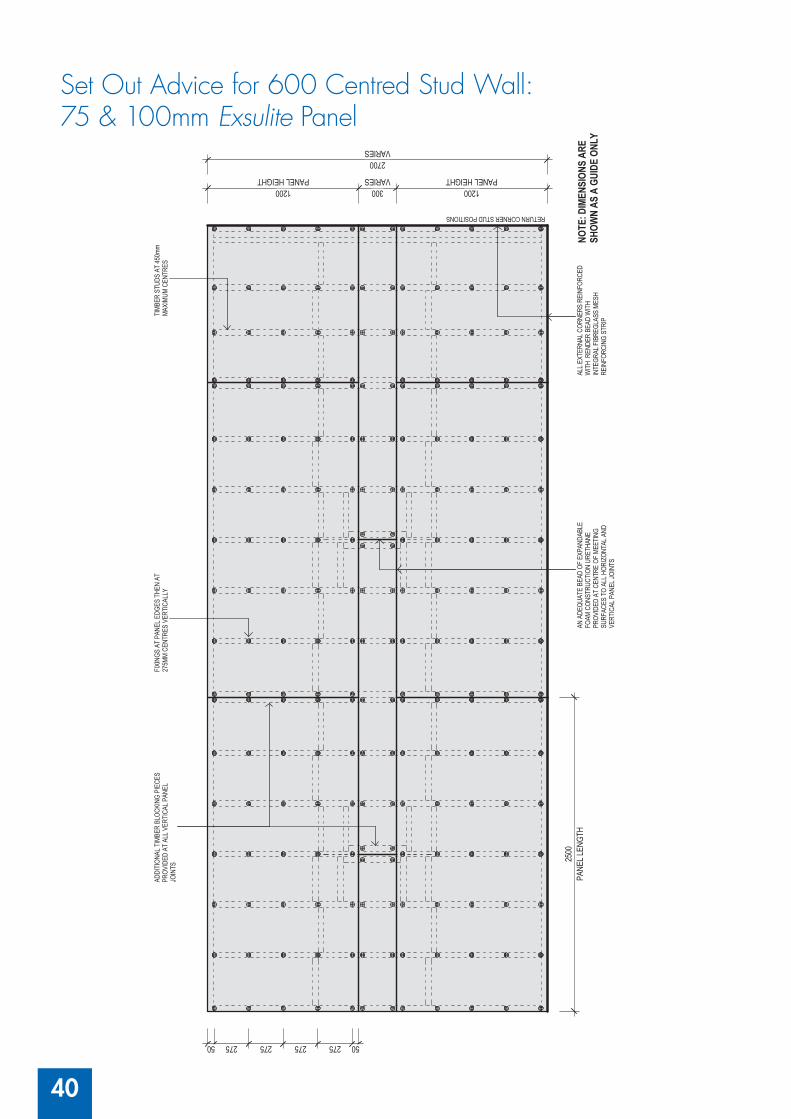
40
PANE
L LEN
GTH
2500
PANEL HEIGHT1200
VARIES300
PANEL HEIGHT1200
VARIES2700
5027527527527550
RETURN CORNER STUD POSITIONS
SET
OUT
ADVI
CE F
OR 45
0 CEN
TRED
STU
D W
ALL:
ADDI
TION
AL T
IMBE
R BL
OCKI
NG P
IECE
SPR
OVID
ED A
T AL
L VER
TICA
L PAN
ELJO
INTS
TIMB
ER S
TUDS
AT
450m
mMA
XIMU
M CE
NTRE
S
ALL E
XTER
NAL C
ORNE
RS R
EINF
ORCE
DW
ITH
REN
DER
BEAD
WIT
HIN
TEGR
AL F
IBRE
GLAS
S ME
SHRE
INFO
RCIN
G ST
RIP
60, 7
5 & 10
0MM
EXSU
LITE
PANE
L
NOTE
: DIM
ENSI
ONS
ARE
SHOW
N AS
A G
UIDE
ONL
Y
FIXI
NGS
AT P
ANEL
EDG
ES T
HEN
AT27
5MM
CENT
RES
VERT
ICAL
LY
AN A
DEQU
ATE
BEAD
OF
EXPA
NDAB
LEFO
AM C
ONST
RUCT
ION
URET
HANE
PROV
IDED
AT
CENT
RE O
F ME
ETIN
GSU
RFAC
ES T
O AL
L HOR
IZON
TAL A
NDVE
RTIC
AL P
ANEL
JOIN
TS
Set Out Advice for 600 Centred Stud Wall: 75 & 100mm Exsulite Panel
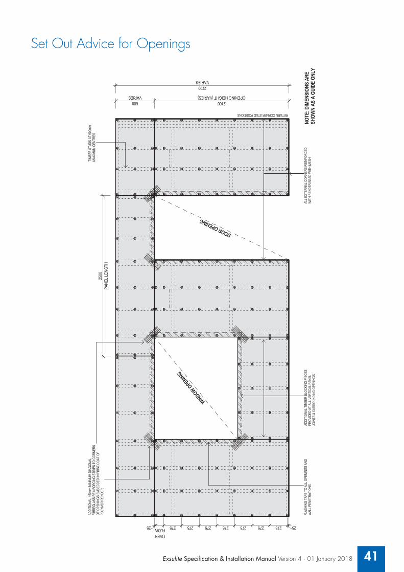
Exsulite Specification & Installation Manual Version 4 · 01 January 2018 41
DOOROPENING
WINDOW OPENING
OPENING HEIGHT (VARIES)2100
VARIES600
VARIES2700
RETURN CORNER STUD POSITIONS
SET
OUT
ADVI
CE F
OR O
PENI
NGS:
ADDI
TION
AL 15
0mm
MINI
MUM
DIAG
ONAL
FIBR
EGLA
SS R
EINF
ORCI
NG S
TRIP
S TO
COR
NERS
OF O
PENI
NGS
EMBE
DDED
IN F
IRST
COA
T OF
POLY
MER
REND
ERPA
NEL L
ENGT
H25
00
TIMB
ER S
TUDS
AT
600m
mMA
XIMU
M CE
NTRE
S
FLAS
HING
TAP
E TO
ALL
OPE
NING
S AN
DW
ALL P
ENET
RATI
ONS
ADDI
TION
AL T
IMBE
R BL
OCKI
NG P
IECE
SPR
OVID
ED A
T AL
L VER
TICA
L PAN
ELJO
INTS
& S
URRO
UNDI
NG O
PENI
NGS
ALL E
XTER
NAL C
ORNE
RS R
EINF
ORCE
DW
ITH
REND
ER B
EAD
WIT
H ME
SH
60, 7
5 & 10
0MM
EXSU
LITE
PANE
L
NOTE
: DIM
ENSI
ONS
ARE
SHOW
N AS
A G
UIDE
ONL
Y
25275275275275275275275FLOWOVER
25Set Out Advice for Openings

42
2.2.13 Exsulite EPS Panel & Composite Panel Fixing:Measure and cut Exsulite panels using a masonry diamond blade in a standard power saw or a sharp knife.
The panel to be installed oriented horizontally with a staggered horizontal brick pattern layout and fixed at maximum 275mm centres on stud lines subject to wind pressures. Exsulite fixings are to be used in all cases with no substitution allowed of non-approved alternative fixings. Fixings should be started at 50mm from the top and bottom of the sheet. Typically 5 fixings are used per stud line, subject site specific wind classification.
Expanding adhesive foam is to be applied to all panel edges during installation and once all wall area are installed expanding adhesive foam is to be applied to between all panel voids flush with face of panel.
The panel is required to be fixed to the stud, extra supporting (back blocking refer to Exsulite Construction Drawings EXS901.3 for clarity) members will be required at panel joints so each panel is individually fixed. Panels must not protrude beyond the cavity spacer. Back blocking allows for joining off stud, refer to page 36.
NOTE: Adhesive fixed back blocking & merchant grade timber is not allowed. No two panels are to be joined on one stud
Work upwards to the soffit then from the bottom of the first run of sheets. Fix that run of sheets to the line, leaving a 5mm gap between the two runs of sheets for expansion. Then work down towards the bottom of sheets that have been fitted to the starter channel.
Once the two runs of sheets have been fixed you will be required to cut a piece to fit in between the panels and complete the cladding side of your first wall. Using a Dulux AcraTex approved expanding foam adhesive, spray onto all panel edges where the panel is to be joined.
2.2.14 Exsulite Fixing Disks & Screws – In accordance with Tables 1, 2 and 3 re wind design:For 600mm stud centres: The required fixings are 5 per stud, fixed at a maximum 275mm centres and 50mm from the top and 50mm from the bottom edge with a minimum 30mm penetration into timber frame. (Minimum is 25 fixings per panel including sheet ends subject to project requirements & wind design).
For 450mm stud centres: The required fixings are 5 per stud, fixed at a maximum 275mm centres and 50mm from the top and 50mm from the bottom edge with a minimum 30mm penetration into timber frame. (Minimum is 25 fixings per panel including sheet ends subject to project requirements & wind design).
2.2.15 Adhesives:Once the wall panels have been fixed, spray adhesive expanding foam approved and supplied only by Dulux AcraTex into all panel joints. Once dry, cut off excess with a knife and then sand all joins flush. When the total thickness is greater than 50mm, apply in multiple layers moisturising each layer.
2.2.16 Control Joints:Good building practice provides for expansion joints at maximum 3m height & 6m wide intervals and at all building weak points or where potential cracking may occur e.g. in line with openings (windows / doors), horizontally between floor levels and at all interfaces of different building construction materials and / or as defined by the responsible Building Engineer. The placement and correct installation of control joints is the responsibility of the Building Engineer / Builder relative to the construction design.

Exsulite Specification & Installation Manual Version 4 · 01 January 2018 43
2.2.17 Corner Details:Corners are butt joined and glued together with a suitable construction adhesive approved and supplied by Dulux AcraTex being expanding adhesive foam. Refer to “Exsulite Construction Drawings Manual” for corner details.
2.2.18 Window Details: The panel is fixed to the window head and sill as per section details with the reveals finished. Exsulite UV-PVC angles should be fixed on all panel edges of door and window reveals and thoroughly glued with construction adhesive and suitably covered with mesh and or reinforced.
Underneath all window sills, leave a 10mm-12mm gap and fit external trims around window. Fill the gap with an approved and supplied by Dulux AcraTex construction foam adhesive and when dry, cut off flush with the bottom of the window. This will allow adequate fall on the window sills at render stage. Refer to “Exsulite Construction Drawings Manual” for window details.
2.2.19 Parapet Detail:Metal flashing is the preferred recommendation for waterproofing and should be approved by the project consultant, refer to “Exsulite Construction Drawings Manual” for preferred parapet detail. Where alternative waterproofing detail is required please refer to the “Exsulite Construction Drawings Manual” for alternative parapet details panels.
2.2.20 Balcony & Terraces:Where waterproofing is required, this should be in accordance with the project specification and project principal. Where alternative waterproofing detail is required please refer to the “Exsulite Construction Drawings Manual” for balcony details.
2.2.21 Exsulite External Beads & Angles:Once all of the wall area has been installed, it is important to go around with a straight edge and make sure that all external corners are plumb and true. Rasp off using sandpaper to make sure that all edges are perfectly straight and ready for installation for corner angles & beading.
Install 3.5mm Exsulite external bead with Selleys Liquid Nails Fast down the centre of both sides and one run of glue in the junction of the bead. Cut a 45 degree angle on both ends of the bead so it finishes flush with the soffit at the top and flush with the starter bead at the bottom. Once fitted check it using a straight edge for straightness and wipe off excess glue protruding through slots in the bead.
NOTE: External beads must be installed where the panels are installed adjacent to another substrate ie. brick & timber.

44
2.2.22 Joint Sealant: Install Selleys Flexiseal PU sealant around all window & door frames, all openings, penetrations, electrical meter boxes, ducting, floor & joist penetrations, the gap that appears in between where different substrates meet and all other penetrations including plumbing and electrical conduit.
NOTE: Joint sealant can only be applied once the Exsulite Texture coating has been completed and before the Exsulite Membrane weatherproof topcoat.
(Refer to the Selleys Flexiseal Product Data Sheet for installation guidelines and to the Exsulite Construction Drawings for details).
2.2.23 Quality Control:During the installation works as per above, the Dulux AcraTex Exsulite Trained & Registered Installer will complete the “Exsulite Certificate of Installation Installer Check List” to ensure job quality control. This then forms part of the project QC documentation confirming that the Dulux AcraTex Exsulite Trained & Registered Installer has installed in accordance with the Exsulite Facade System Specification & Installation Manual and is handed over to the project principal.
2.2.24 Weather & Temperature:Weather conditions can affect application and drying time. Hot or dry conditions and limited working time can accelerate drying times and may require adjustments in the scheduling of work to achieve desired results (different to working times in the shade). Cool or damp conditions extend working and drying times and may require added measures of protection against wind, dust, dirt and rain. Refer to product data sheets for application guidelines and conditions prior to work commencing.

Exsulite Specification & Installation Manual Version 4 · 01 January 2018 45
2.3.0 Exsulite Finishing System Application
Exsulite Matrix Basecoat or RenderWall® P400 with Exsulite Mesh;In a clean 15 litre pail add 3.5-4 litres of clean water, slowly add Exsulite Matrix Basecoat or RenderWall P400 while stirring until a cream trowelable paste is formed. Apply the basecoat layer of Exsulite Matrix Basecoat by stainless steel trowel to fully cover the panel surface with a 2-3 mm (min.) cover. Refer to the Exsulite Matrix Basecoat data sheet & application data sheet for full details. Approximate material usage of 1.7kg / m2 / mm will vary with application technique.
Embed Exsulite Reinforcement Mesh into the ‘wet’ freshly applied Exsulite Matrix Basecoat layer. The Exsulite reinforcing mesh: (165gsm, 5mm x 5mm aperture). Once Exsulite mesh is installed and overlapped by a minimum of 100mm on all edges, immediately apply additional Exsulite Matrix Basecoat or RenderWall P400 mixture to completely cover and encapsulate the mesh with a minimum of 2mm cover and an overall minimum total thickness of 5mm.
NOTE: Full layer of Exsulite Mesh is recommended with Exsulite Matrix Basecoat or RenderWall P400 over Exsulite Pre-coated Composite Panels to the entire wall area. It is recommended that additional mesh layer is to be installed to internal corners, edge reveals, and at diagonals across corners of all windows & door openings. Where additional impact resistance is needed apply an additional layer of Exsulite mesh with Exsulite Matrix Basecoat or RenderWall P400. Do not push the mesh to the surface of the cladding. Finish the Exsulite Matrix base coat layer by lightly scratching the surface to provide a surface “key” for subsequent levelling coats.
Where texture coating application is to occur within 7 days of Exsulite Matrix Basecoat or RenderWall P400 completion, Dulux AcraTex recommends that one coat of Dulux AcraTex Green Render Sealer – a high alkali resistant primer is applied in accordance with relevant product data sheets. It will help consolidate the surface and enhance subsequent coating application and provide total system durability.
Exsulite Texture Coating;Apply one coat of Exsulite Texture (or an approved AcraTex texture coating) @ 0.8m2 / L in accordance with the relevant product data & application data sheets.
PU Sealant Application; Install Selleys Flexiseal PU sealant or other approved sealant around all window & door frames, all openings, penetrations, electrical meter boxes, ducting, floor & joist penetrations, fixings and any gap that appears where different substrates meet and all other penetrations including plumbing and electrical conduit.
NOTE: Joint Sealant can only be applied once the Exsulite Texture coating has been completed and before the Exsulite weatherproof membrane topcoat.
Exsulite Membrane Weatherproof protective top coat(s); Apply Exsulite Membrane or AcraShield Advance or AcraSkin in accordance with the relevant product data and application data sheets.
NOTE: Material consumption will vary pending on surface porosity and application technique allowance is to be made when estimating material quantities. Spread rates nominated are theoretical maximum rates required to achieve the specified film builds for technical performance.

46
2.3.1 Standards Of Finish / Variation / Modifications / Precautions:Dulux AcraTex does not approve nor endorse the use of any non-standard or non-approved Dulux AcraTex Exsulite Thermal Facade System Specification and or Components. Dulux AcraTex will not be responsible for the performance of a system when installed outside the CodeMark accreditation and system limitations and when non-standard or non-approved components are used. The use of any non-standard or non-approved components will compromise the system and no product warranty will be issued for the system.
Design samples approved by the Contractor/Builder are provided as indicative examples only and are not intended as finished examples of onsite application. The appearance of the finished system shall, as near as practicable, match the approved “onsite sample” in terms of installation details, texture, colour and uniformity. Permissible variation and due regard shall be given for textural variation owing to multiple applicators, onsite restraints, scaffold limitations and angle or side light or illumination accentuating surface irregularities.
The manufacturers recommendations for installation and application as specified in the installation & application guidelines must be observed at all times. The coating system must not be applied when rain is anticipated. Adequate protection against rain and dust must be provided for the coating during application. During periods of high temperature above +30°C, work needs to be scheduled during the coolest part of the day and away from direct sunlight. During periods of cooler temperatures 10-18°C, work needs to be scheduled during the morning and completed with adequate time to allow the coating to form a coherent film before the temperature falls below 10°C this is particularly important on exposed southern elevations and may require assistance to dry.

Exsulite Specification & Installation Manual Version 4 · 01 January 2018 47
2.4.0 Care & Maintenance The exterior coatings should be cleaned on a regular basis. This will help maintain your coatings aesthetic appearance and preserve your Dulux AcraTex Texture coating system. Cleaning on an annual basis will remove light soil as well as grime and airborne pollutants. Coastal exposure will have a build-up of salt contamination and a six month wash down is recommended. All joint sealants should be regularly checked to ensure no cracking is evident to allow water ingress. Where cracking is evident, sealant will need to be replaced immediately.
The exterior can be cleaned with a low-pressure water blast (less than 450psi) using a fanjet of cold water at a 45 degree angle from the wall (not perpendicular).The fan of the water blaster should be kept a minimum of 30cm from the surface of the Dulux AcraTex Texture coating in order to avoid damage.
Localised grime or ingrained dirt should be removed by cleaning with a scrubbing brush along with a solution of detergent and warm water. Under no circumstances should you attempt to remove heavy staining using a high-pressure water blaster.
Check for cracked, loose or missing sealant as part of your regular maintenance inspections. You will find sealant in most areas where different substrates meet ie. Above door openings & windows, pipes, where walls meet the soffit line and where electrical fittings and handrails have been attached to walls. Control joints should also be inspected as part of maintenance inspections. All deteriorated or damaged sealant should be removed and replaced as soon as it is apparent. We recommend that a paintable polyurethane sealant be used.
It is important to monitor areas that are heavily exposed to the elements such as parapets and balcony handrail tops. Due to the minimal slope on these areas it will tend to hold dirt and grime which can potentially lead to mould over time if not regularly washed. These building sections should also be checked for any movement over time due to the extremes of thermal movement so it is critical that they are inspected and maintained.
Any damage to the texture coating needs to be recoated from edge to edge of the effected wall area to ensure texture and colour consistency. If accidental damage occurs please feel free to contact your local Dulux AcraTex representative or phone Dulux AcraTex Customer Service on “1300 662 841” and they will provide the support or technical expertise required to help solve the problem. Visual cracks may indicate underlying structural problems; a professional should always inspect them.
Temporary repairs can be made to cracks by filling them with polyurethane paintable sealant until the inspection has been completed and permanent repairs undertaken.
During your inspections don’t forget to check areas that are cold and dark such as behind heavy foliage. Dirt provides the perfect nutrient for mould and algae growth. The tiny roots that these organisms use to cling to your walls will cause your texture coating to deteriorate very quickly if not regularly cleaned.
Recoating is recommended after a minimum of 10 years to rejuvenate the surface appearance. This can be done by using Dulux AcraTex AcraSkin protective membrane coating to a selected Dulux AcraTex colour which will protect from air pollutants, water ingress and dirt accumulation to provide a new low maintenance surface.
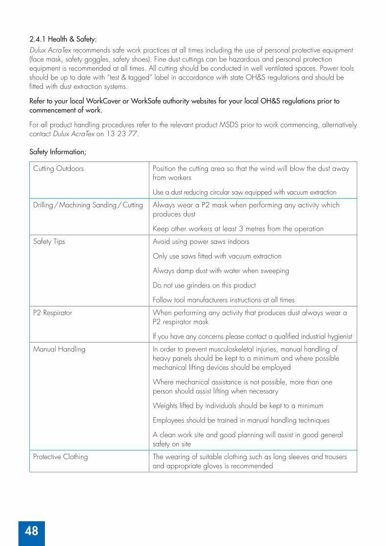
48
2.4.1 Health & Safety: Dulux AcraTex recommends safe work practices at all times including the use of personal protective equipment (face mask, safety goggles, safety shoes). Fine dust cuttings can be hazardous and personal protection equipment is recommended at all times. All cutting should be conducted in well ventilated spaces. Power tools should be up to date with “test & tagged” label in accordance with state OH&S regulations and should be fitted with dust extraction systems.
Refer to your local WorkCover or WorkSafe authority websites for your local OH&S regulations prior to commencement of work.
For all product handling procedures refer to the relevant product MSDS prior to work commencing, alternatively contact Dulux AcraTex on 13 23 77.
Safety Information;
Cutting Outdoors Position the cutting area so that the wind will blow the dust away from workers
Use a dust reducing circular saw equipped with vacuum extraction
Drilling / Machining Sanding / Cutting Always wear a P2 mask when performing any activity which produces dust
Keep other workers at least 3 metres from the operation
Safety Tips Avoid using power saws indoors
Only use saws fitted with vacuum extraction
Always damp dust with water when sweeping
Do not use grinders on this product
Follow tool manufacturers instructions at all times
P2 Respirator When performing any activity that produces dust always wear a P2 respirator mask
If you have any concerns please contact a qualified industrial hygienist
Manual Handling In order to prevent musculoskeletal injuries, manual handling of heavy panels should be kept to a minimum and where possible mechanical lifting devices should be employed
Where mechanical assistance is not possible, more than one person should assist lifting when necessary
Weights lifted by individuals should be kept to a minimum
Employees should be trained in manual handling techniques
A clean work site and good planning will assist in good general safety on site
Protective Clothing The wearing of suitable clothing such as long sleeves and trousers and appropriate gloves is recommended

How Exsulite® Installers Set The Standard
Certificate of Installation confirms installation is in accordance with project specifications and system installation guidelines.
1. Training and development to meet industry and quality assurance standards• Exsulite trains five levels of installers • On-going development and refresher courses• Adapts to changing industry practices and needs
2. Job Quality Control Procedures• Certificate of Installation at job completion• Job registration and warranty process• No component substitution• Job sign-off process
3. System Compliance• Structural Performance• Energy Efficiency• Weatherproofing• Bushfire Attack Level 29• Meet BCA Requirements as an ‘Alternative Solution’
4. Surveyor and Builder Certification Solutions• Full design and supply from Dulux®
• Installation by a trained and registered installer• Single integrated warranty covering cladding
and coating system.
All Exsulite Trained Installers can be verified by their personal Exsulite Identification Card as proof they have been trained and are accredited as an Exsulite partner.

647
1/0
416
The Exsulite® “Certifi cate of Installation” is for use by a Exsulite Trained & Registered Installer as a Quality Control Document that verifi es that the specifi ed Exsulite system has been installed in accordance with the Exsulite Installation procedures as set out in the Exsulite Specifi cation & Installation manual, Exsulite Construction Drawings manual & Dulux® AcraTex® specifi cation.
The “Certifi cate of Installation” is used to record on site work procedures & substrate standards for the Installation of the Exsulite Thermal Facade System and the Application of Dulux AcraTex fi nishing system, signed off & handed over at job completion.
The Exsulite “Certifi cate of Installation” and Exsulite Warranty Job Registration forms are required for warranty purposes and forms part of the Exsulite warranty procedure. The Exsulite Trained Installer and Exsulite Trained Finisher can either be the same or separate entities who have attended the Exsulite Training Course.
System Used (Please tick one):
Exsulite Thermal Facade Cavity System Exsulite Composite Thermal Facade Cavity System
Exsulite-Kooltherm® Thermal Facade System
Certifi cate of Installation
Page 1 of 3
Project InformationProject Start Date Timber Frame Steel Frame
Site Address
Within 1km of Coastal Area Wind pressures confi rmed by engineer
Project Builder Contact Number
Contact Name
Ground Level Construction Exsulite AAC Brick Other
Upper Level Construction Exsulite AAC Brick Other
Exsulite Panel Wall Area m2 Dulux Specifi cation Number
Exsulite Trained Installer EntityCompany Name Installer Name
Exsulite Installer No.
Nominated Installer Mobile
Nominated Installer No
Exsulite Trained Finisher EntityCompany Name Installer Name
Exsulite Installer No.
Nominated Installer Mobile
Nominated Installer No
Site Access and Scaffolding Checklist Yes No Comments / By WhoIs all access scaffolding set up to install the specifi ed system?
Is all scaffolding and access equipment checked and approved?
Installer Checklist Yes No Comments / By WhoAll Exsulite components supplied by Dulux with no substitution
Frame tolerance 4mm in any 2m length.
Was rectifi cation required and if so by whom?
Additional back blocking to ensure double studs are installed where needed.

647
1/0
416
Page 2 of 3
Installer Checklist (continued) Yes No Comments / By WhoBack blocking required and if so by who.
Checked expansion joint locations and ensured double studs.
Vertical expansions joints installed at max. 6.0m centres (Refer to Exsulite Construction Drawings manual for details) or as approved by engineer.
Horizontal expansions joints installed at max. 3.0m centres (Refer to Exsulite Construction Drawings manual for details) or as approved by engineer.
Backing plates for fi xing of down pipe brackets before panel installation.
Backing plates to clothes lines, pergolas and other external fi xtures.
Checked fl ashing installed over roof areas, parapets and balconies.
Checked windows and doors installed with correct reveal size to suit cavity.
Damp proof course installed to slab rebate.
• Exsulite breathable absorbent wall wrap installed.
• If not, state alternative breathable wrap installed.
• Exsulite Cavity spacer installed. Cavity spacer thickness mm
• If not, type of cavity spacer installed and by who. Type mm
Panel Type
Exsulite EPS Raw Panel 60mm 75mm 80mm 100mm Other
Exsulite Composite Panel 60mm 75mm 80mm 100mm Other
Exsulite-Kooltherm Panel 50mm 80mm Other
Exsulite screws and washers installed at maximum 275mm vertically and maximum 600mm horizontally subject to system specifi cation and wind pressures.
Back blocking installed at panel joints when fi xing off stud in accordance with Exsulite Construction Drawings manual.
Approved aluminium fl ashing tape installed around windows, doors, meter box, openings and all penetrations.
Exsulite panels glued fully along abutting edges with approved foam adhesive.
All exposed panel edges fully enclosed with PVC channel or as approved.
Exsulite cavity closer with weep holes.
Exsulite Starter Piece
Exsulite PVC external angles fi xed with approved adhesive.
Control Joints to masonry with 10mm gap and backing rod/strip.
Exsulite panel to window sills cut at minimum 10 degrees.
Detail at concrete slab rebate in accordance with Exsulite Construction details.
All components have been installed fully in accordance with Exsulite Installation Manual and Construction Details.
Collected all off cuts and placed in clear plastic bags for recycling collection.
Installer sign-off
Name Installer No: Signature: Date of completion

647
1/0
416
On completion of this form, it is the responsibility of the Exsulite Trained Installer to forward it to Dulux AcraTex by email to [email protected] or by fax to +61 8 8347 1963 as part of job registration process.Dulux® AcraTex® is a division of DuluxGroup (Australia) Pty Ltd. ABN 67 000 049 427. Dulux®, AcraTex® and Exsulite® are registered trade marks and AcraPrime™ and Matrix Basecoat™ are trade marks of DuluxGroup (Australia) Pty Ltd. Kooltherm® is a registered trade mark of Kingspan Holdings (IRL) Limited. Page 3 of 3
Finisher ChecklistApplied PU sealant to expansion joints, control joints, and around windows, meter box and other penetrations. (Do not overcoat sealant with Basecoat or Texture. Overcoat only with membrane.)
Yes NoComments:
External PVC angles installed and by who. Yes No By Who
Protective drop sheets to roof and adjacent areas. Yes No
AcraTex AcraPrime™ XPS Primer applied (Kooltherm only). Must be applied over Exsulite-Kooltherm panel prior to Exsulite Matrix Basecoat™.
Yes NoComments:
Exsulite Matrix Basecoat applied.Date: Batch No: Quantity (bags):
Comments:
Exsulite mesh embedded into basecoat, overlapped min. 100mm, diagonal strips at corners of openings. Yes No Comments:
Green Render Sealer (when texture coating within 5 days of base coat application). Yes No
Date: Comments:
Exsulite Texture coat applied.Date: Batch No: Quantity (buckets):
Product: Colour: Comments:
Exsulite Membrane top coat applied.Date: Batch No: Quantity (buckets):
Product: Colour: Comments:
Applied in accordance with Dulux AcraTex/Exsulite product data sheets and product specifi cations Yes No Comments:
Finisher sign-off
Name: Installer No: Signature: Date of completion:
Project Specifi c Checklist
Item/Description Yes No Comments/By Who
Other Comments

PART
A N
OTE
: Mus
t be
faxe
d or
em
aile
d w
ith a
cop
y of
you
r job
ord
er a
nd D
ulux
® a
ppro
ved
Spec
ifi ca
tion
to D
ulux
Acr
aTex
® F
AX
(08
) 834
7 19
63 o
r EM
AIL
sale
s@ex
sulite
.com
.au
Date Dulux Representative
Installer Company
Installer Company ABN
Nominated Trained Installer
Nominated Installer Reg. Number
Job Name
Job Address
Builder Builders Contact
Job Size Installed
m2Dulux Specifi cation Number
Scope of Works
Commencement Date
Where stock was purchased (DTC)
(At job completion, please provide a copy of the completed and signed Exsulite® Installer ‘Certifi cate of Installation’ along with the ‘Materials Usage’ form to obtain a Dulux Material Warranty)
PART
B
AUTHORITY
John DimoglidisShane LangkildeMatt RogersonIan Schultz
Project Number E Date of Issue
PART
C
INSTALLER COMPLETION STATEMENT
I hereby certify that I have provided Dulux with the correct project information by completing and signing the Exsulite ‘Installer Certifi cate of Installation’. The above system has been installed in accordance with the Dulux AcraTex project specifi cation and Exsulite installation procedure as part of my Exsulite Installer Workmanship Warranty.
Print Name Date of completion
Signature
6290
/071
5
Revision #2 Wednesday, 1 July 2015Page 1 of 1
EXSULITE JOB REGISTRATION & WARRANTY REQUEST FORM

6290
/07
15
Page 1 of 2
Trained Installer Workmanship Warranty
SAMPLE
Installer
Installer’s Registration No.
Project Name
Project Address
Insert m2
Installation Completion Date
Dulux Specifi cation No.
Installer warranty in respect of the installed system is made up of the terms set out expressly in this document (the Warranty). The benefi ts of the Warranty are in addition to other rights and remedies under any applicable law.
The Warranty
Installer hereby confi rms and warrants to the Customer that the products and components of the Exsulite® System have been installed to the Project in strict accordance with the instructions and recommendations provided by or available from Dulux® and will comply with the relevant Dulux products and component performance specifi cation(s) as stated above and that the Installer will be responsible for any loss or damage caused or contributed to by its faulty installation.
The Installer’s workmanship is warranted for a period of (XX) years against faulty or defective installation resulting in a failure of the installed system. If, subject to the terms of the Warranty, the installation is not in accordance with the specifi cation and Dulux Exsulite documented product components and installation recommendations causing premature failure, Installer will:
(a) repair the installed system to an equivalent standard;
(b) pay the cost of having the installed system repaired;
In these circumstances, the Installer will have full discretion to choose which of the above actions are undertaken to remedy the situation.
The Warranty is personal to the Customer and supersedes any and all other prior agreements and understandings between the parties in relation to its subject matter.
Limitations of the Warranty
1. Installer will not be liable under the Warranty if the substrate on which the Exsulite System is installed to:
(a) is not of a standard and fi tness meeting all statutory requirements and building code standards.
2. Installer will not be liable under the Warranty for any loss or damage wholly or partly caused by one or more of:
(a) hydrostatic pressure, settling, movement, cracking, lifting, peeling, fl aking, failure or other deterioration of the substrate; or
(b) corrosion, ingress of moisture or other contaminants, maltreatment, excessive wear/tear, staining or discolouration;
(c) faulty design and / or construction of the building;
(d) without limitation any other cause outside the reasonable control of Installer;
3. Installer will not be liable under the Warranty if another coating has been applied over the installed system;

6290
/07
15
Page 2 of 2
Trained Installer Workmanship Warranty
SAMPLE
4. Installer will not be liable under the Warranty unless the Customer makes a claim pursuant to the procedure set out in this Warranty.
5. Installer will not be liable under the Warranty for any consequential or indirect loss of any kind or loss of income, profi t, business, goodwill or reputation arising out of or in any way connected with the installation of the installed system; and
6. Except as expressly provided to the contrary in the Warranty, Installer will be under no liability in respect to any loss or damage howsoever caused and whether arising directly or indirectly out of negligence or otherwise.
Making a claim under the Warranty
The Customer must give Installer written notice of any claim pursuant to the Warranty within fourteen (14) days of any defect coming to the Customer’s notice and within ninety (90) days of the defect becoming apparent.
The Customer must contact Installer by post at:
Installer: _______________________________________________________________________________________________
Installer Address: ________________________________________________________________________________________
______________________________________________________________________________________________________
The Customer must show proof of purchase and bear all expenses incurred in making a claim.
Our services come with guarantees that cannot be excluded under the Australian Consumer Law. You are entitled to a replacement or refund for a major failure and compensation for any other reasonably foreseeable loss or damage. You are also entitled to have the goods repaired or replaced if the goods fail to be of acceptable quality and the failure does not amount to a major failure.
Dated this day of 2015
Signed: _________________________________________ Name: _______________________________________________
On behalf of Installer
Installer Registration Number : ______________________ Position: _______________________________________________

6290
/07
15
Page 1 of 2
Dulux® AcraTex® Exsulite®
Material Warranty
SAMPLE
Material Warranty
Installer Customer Name
Installer’s Registration No.
Project Name
Project Address
Insert m2
Installation Completion Date
Dulux Specifi cation No.
Dulux’s warranty in respect of the installed Dulux products and components of the Exsulite system is made up of the terms set out expressly in this document (the Warranty). The benefi ts of the Warranty are in addition to other rights and remedies under any applicable law.
The Warranty
Dulux warrants to the Customer that the Dulux products and components of the Exsulite system when installed to the Project in accordance with the Dulux Specifi cation Number, as stated above, by the Exsulite Installer will comply with the relevant Dulux products and component performance specifi cation(s). The Warranty applies for [XX] years [from the date of purchase]. If, subject to the terms of the Warranty, the products and components do not comply with the Dulux Specifi cation(s), Dulux will:
(a) replace the installed system or supply an equivalent system;
(b) repair the installed system;
In these circumstances, Dulux will have full discretion to choose which of the above actions are undertaken to remedy the situation. The Warranty is personal to the Customer and supersedes any and all other prior agreements and understandings between the parties in relation to its subject matter.
Limitations of the Warranty
1. Dulux will not be liable under the warranty for installation or supervision of installation.
2. Dulux will not be liable under the Warranty if the installation Dulux products and components of the Exsulite system is not in strict accordance with the instructions provided by or available from Dulux including the Specifi cation;
3. Dulux will not be liable under the Warranty if the substrate on which the Exsulite system is installed to:
(a) is not of a standard and fi tness meeting all statutory requirements and building code standards; or
(b) has not been prepared strictly in accordance with the instructions provided by or available from Dulux including the Specifi cation;
4. Dulux will not be liable under the Warranty for any loss or damage wholly or partly caused by one or more of:
(a) hydrostatic pressure, settling, movement, cracking, lifting, peeling, fl aking, failure or other deterioration of the substrate or previous coating or non compliance products; or
(b) corrosion, ingress of moisture or other contaminants, maltreatment, excessive wear / tear, staining or discolouration; or
(c) faulty design and / or construction of the building; or
(d) defective products manufactured by a third party and supplied or specifi ed by Dulux provided that Dulux has notifi ed Customer that the product is a third party product; or
(e) without limitation any other cause outside the reasonable control of Dulux;

6290
/07
15
Page 2 of 2
Dulux® AcraTex® Exsulite®
Material Warranty
SAMPLE
5. Dulux will not be liable under the Warranty if another non compliant product(s) or coating has been applied to or used in the Exsulite system;
6. Dulux will not be liable under the Warranty unless the Customer makes a claim pursuant to the procedure set out in this Warranty;
7. Dulux will not be liable under the Warranty unless the Installer has signed the Installer’s Confi rmation below;
8. Dulux will not be liable under the Warranty for any consequential or indirect loss of any kind or loss of income, profi t, business, goodwill or reputation arising out of or in any way connected with the sale or application of the coating system; and
9. Except as expressly provided to the contrary in the Warranty, Dulux will be under no liability in respect to any loss or damage howsoever caused and whether arising directly or indirectly out of negligence or otherwise
Making a claim under the Warranty
The Customer must give Dulux written notice of any claim pursuant to the Warranty within fourteen (14) days of any defect coming to the Customer’s notice and within ninety (90) days of the defect becoming apparent.
The Customer must contact Dulux by post: Dulux Admin [insert relevant address], telephone [insert telephone number] or email [insert email address if any]. The Customer must show proof of purchase and bear all expenses incurred in making a claim.
Our goods come with guarantees that cannot be excluded under the Australian Consumer Law. You are entitled to a replacement or refund for a major failure and compensation for any other reasonably foreseeable loss or damage. You are also entitled to have the goods repaired or replaced if the goods fail to be of acceptable quality and the failure does not amount to a major failure.
Dated this day of 2015
Signed: _________________________________________ Name: _______________________________________________
On behalf of Dulux
Exsulite Trained Installer’s Confi rmation
The Installer hereby confi rms that the Dulux products and components of the Exsulite system were installed to the Project in strict accordance with the instructions provided by or available from Dulux including the Dulux Specifi cation, and that the Installer will be responsible for any loss or damage caused or contributed to by its faulty application.
Dated this day of 2015
Installer Company Name: ________________________________________________________________________________
Installer Registration Number: ________________ Installer Name: _______________________________________________
Signed: _________________________________________ Name: _______________________________________________
On behalf of the Installer
**IMPORTANT: Please note the Warranty is Invalid if a Customer’s signed copy is not returned to Dulux AcraTex at 1 Jeanes St, Beverly SA 5009 or the Account Manager responsible for the account within 30 working days of Managers Signature.

This page has been left blank intentionally


7024
/081
8-Ex
sulit
e
For further information go to www.exsulite.com.auDulux AcraTex Customer Service 1300 662 841
1 Jeanes Street, Beverley SA 5009 AustraliaDulux AcraTex is a division of DuluxGroup (Australia) Pty Ltd. ABN 67 000 049 427.
Dulux, AcraTex, Exsulite, AcraShield, RenderWall, Selleys and Liquid Nails are registered trade marks of DuluxGroup (Australia) Pty Ltd.
AcraSkin, Green Render Sealer and Matrix Basecoat are trade marks of DuluxGroup (Australia) Pty Ltd.
Bradford is a trade mark of CSR Building Products Limited.