Expression of Interest Invitation for discussion on ...
131
Expression of Interest Invitation for discussion on Provision of Long Term Evolution (LTE) for Mission Critical Applications for Indian Railways Indian Railways is planning to launch Long Term Evolution based Mobile Train Radio Communication for its Mission Critical applications. Industry experts are invited for their valuable comments and suggestions during the workshop being held on 08/09/2021 to 09/09/2021 in conference hall, 3 rd floor, Rail Nilayam, South Central Railway, Secunderabad. It is requested to send your communication details to the email id [email protected] (or) [email protected] by 06/09/2021. A power point presentation on the issues for deployment of LTE for 45 minutes may be also got prepared. During the course of presentation only the presenting firm is requested to interact. The other firms can note down their comments and hand it over to the undersigned after the conclusion of the workshop. The Technical Advisory Note for Implementation of LTE on Indian Railways and TCAS LTE Radio Modem and Protocol Requirements are attached herewith. In case of any clarification, please feel free to contact the Shri V N M Rao, CSTE/P-I/SC through above e-mail or on +919701370804.
Transcript of Expression of Interest Invitation for discussion on ...

Expression of Interest
Invitation for discussion on Provision of Long Term Evolution (LTE) for Mission Critical Applications for Indian Railways
Indian Railways is planning to launch Long Term Evolution based Mobile Train Radio
Communication for its Mission Critical applications. Industry experts are invited for their
valuable comments and suggestions during the workshop being held on 08/09/2021 to
09/09/2021 in conference hall, 3rd floor, Rail Nilayam, South Central Railway,
Secunderabad.
It is requested to send your communication details to the email id
[email protected] (or) [email protected] by 06/09/2021. A power
point presentation on the issues for deployment of LTE for 45 minutes may be also got
prepared. During the course of presentation only the presenting firm is requested to
interact. The other firms can note down their comments and hand it over to the
undersigned after the conclusion of the workshop.
The Technical Advisory Note for Implementation of LTE on Indian Railways and TCAS
LTE Radio Modem and Protocol Requirements are attached herewith.
In case of any clarification, please feel free to contact the Shri V N M Rao, CSTE/P-I/SC
through above e-mail or on +919701370804.

Page 1 of 104 Implementation of LTE on
Indian Railways
Document No.
STT/TAN/LTE/2021, Version 1.0
Date of Issue
dd.08.2021
Technical Advisory Note (TAN)
on
Implementation of LTE on Indian Railways
Document No. STT/TAN/LTE/2021, Version 1.0
TELECOM DIRECTORATE
RESEARCH DESIGNS & STANDARDS ORGANISATION
LUCKNOW - 226011
(/Final Draft issue date: 03.08.2021/)

Page 2 of 104 Implementation of LTE on
Indian Railways
Document No.
STT/TAN/LTE/2021, Version 1.0
Date of Issue
dd.08.2021
Contents
S. No. Items Page No.
1.0 Scope
1.3 Abbreviations and Description of Terms
2.0 General Requirements
3.0 Architecture of LTE for Indian Railways
Section A General Description and Functional Requirements of
LTE
4.0 General Description and Architecture of LTE System
5.0 Functional Requirements of LTE – Radio Access
Network
(E-UTRAN)
5.1 E-UTRAN Interface Requirements
5.2 E-UTRAN Functional Requirements
5.3 System Specification of eNodeB
5.4 eNodeB (BBU & RRH) Requirements
6.0 Functional Requirements of Evolved Packet Core (EPC)
6.1 Mobility Management Entity (MME)
6.2 Serving Gateway (S-GW)
6.3 Packet Data Network Gateway (PDN-GW)
6.4 Home Subscriber Server (HSS)
6.5 Policy and Charging Rule Function (PCRF)
7.0 Communication Requirements : Future Railway Mobile
Communication System ( FRMCS)
8.0 Mission Critical Services (MCX) Requirements
9.0 LTE (Network access and eNodeB) Security
Requirements
Section B Dimensioning and Implementation of LTE
10.0 System Dimensioning
10.1 Input Data for System Design
10.2 Data rate requirements of IR in LTE
10.3 Cell Edge Throughput and Cell Capacity Calculations
10.4 Design Inputs for Radio Network Planning
10.5 Link Budget
10.6 Path Loss Calculation
10.7 Cell Range and Inter eNodeB Distance

Page 3 of 104 Implementation of LTE on
Indian Railways
Document No.
STT/TAN/LTE/2021, Version 1.0
Date of Issue
dd.08.2021
10.8 Dimensioning of Evolved Packet Core (EPC)
10.9 Network ID Planning & Numbering Scheme
10.9.1 Physical Cell Identity Planning
10.9.2 Numbering Scheme for LTE Network of Indian Railways
10.10 Base Station Antenna & Tower of LTE for Indian
Railways
11.0 User Equipment (UE), On-board Equipment
Requirements and Dispatcher System
11.4 CAB Radio System
11.5 Rail Rooftop Low Profile Antenna
11.6 MCPTT Handset
11.7 Dispatcher System
12.0 Quality of Service (QOS) Requirements
13.0 Reliability, Availability, Maintainability and Safety
(RAMS) Requirements
14.0 Security Aspects and Requirements
15.0 Regulatory Approvals and Certifications and
Environmental Requirements
16.0 Planning, Positioning and Deployment of EPC over
Indian Railway network.
17.0 EPC Deployment/ Redundancy Diagram
18.0 eNodeB Architecture Design and Site Deployment
Scenario : Diagram
19.0 Typical LTE eNodeB deployment on Indian Railway
Track
20.0 Bill of Material/ List of Various components required for
LTE network

Page 4 of 104 Implementation of LTE on
Indian Railways
Document No.
STT/TAN/LTE/2021, Version 1.0
Date of Issue
dd.08.2021
1.0 SCOPE:
1.1 Long Term Evolution (LTE) for Railways, the next generation Mobile Train Radio
Communication System is planned to cater Indian Railways‟ present and future
demands of voice and data. The following main applications/solutions are to be
implemented on LTE:-
i) Indian Railway Automatic Train Protection System (IRATP) through
Train Collision Avoidance System (TCAS) or any other similar systems
as specified by Indian Railways.
ii) Mission Critical Services (MCX) as per FRMCS standards.
iii) Video Surveillance System in locomotives for Level Crossing Gate/
Tunnels/ Bridges.
iv) Onboard Passenger Information System (PIS) consisting of passenger
information display and passenger announcement system.
v) Internet of Things (IoT) based Asset reliability monitoring.
vi) Onboard Video Surveillance System (VSS) for Passenger Security.
vii) Broadband Internet on Running Train (Onboard Wi-Fi facility through
LTE).
1.2 In order to make uniform, cost effective, integrated and standard system over Indian
Railways, a Technical Advisory Note (TAN) on LTE for Indian Railways has been
prepared which includes the followings along with other items :-
i) Architecture of LTE system for Indian Railways
ii) Design inputs for Radio Network Planning, Cell Range and Inter site
(eNodeB) Distance
iii) Dimensioning of EPC (Evolved Packet Core)
iv) Planning, Positioning and Deployment of EPC over Indian Railway
network.
Page 5 of 104 Implementation of LTE on
Indian Railways
Document No.
STT/TAN/LTE/2021, Version 1.0
Date of Issue
dd.08.2021
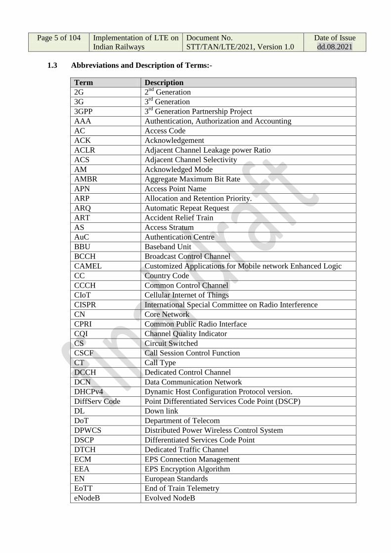
1.3 Abbreviations and Description of Terms:-
Term Description
2G 2nd
Generation
3G 3rd
Generation
3GPP 3rd
Generation Partnership Project
AAA Authentication, Authorization and Accounting
AC Access Code
ACK Acknowledgement
ACLR Adjacent Channel Leakage power Ratio
ACS Adjacent Channel Selectivity
AM Acknowledged Mode
AMBR Aggregate Maximum Bit Rate
APN Access Point Name
ARP Allocation and Retention Priority.
ARQ Automatic Repeat Request
ART Accident Relief Train
AS Access Stratum
AuC Authentication Centre
BBU Baseband Unit
BCCH Broadcast Control Channel
CAMEL Customized Applications for Mobile network Enhanced Logic
CC Country Code
CCCH Common Control Channel
CIoT Cellular Internet of Things
CISPR International Special Committee on Radio Interference
CN Core Network
CPRI Common Public Radio Interface
CQI Channel Quality Indicator
CS Circuit Switched
CSCF Call Session Control Function
CT Call Type
DCCH Dedicated Control Channel
DCN Data Communication Network
DHCPv4 Dynamic Host Configuration Protocol version.
DiffServ Code Point Differentiated Services Code Point (DSCP)
DL Down link
DoT Department of Telecom
DPWCS Distributed Power Wireless Control System
DSCP Differentiated Services Code Point
DTCH Dedicated Traffic Channel
ECM EPS Connection Management
EEA EPS Encryption Algorithm
EN European Standards
EoTT End of Train Telemetry
eNodeB Evolved NodeB

Page 6 of 104 Implementation of LTE on
Indian Railways
Document No.
STT/TAN/LTE/2021, Version 1.0
Date of Issue
dd.08.2021
EPC Evolved Packet Core
EPS Evolved Packet Core
ETCS European Train Control System
ETSI European Telecommunications Standards Institute
E-UTRAN Evolved Universal Terrestrial Access Network
FHD Full HD (High Definition)
GBR Guaranteed Bit Rate
GERAN GSM EDGE Radio Access Network
GMSC Gateway Mobile Switching Center
GRE Generic Routing Encapsulation
GSM Global System for Mobile communication
gsmSCF GSM Service Control Function
GTP General Packet Radio System (GPRS) Tunnelling Protocol
GW(PCEF) Gateway (PCRF)
HARQ Hybrid ARQ
HD High Definition
HLR Home Location Register
HLR Home Location Register
H-PCRF Home PCRF
H-PLMN Home PLMN
HRPD High Rate Packet Data
HSS Home Subscriber Server
HTTPS Hypertext Transfer Protocol Secure
IEC International Electrotechnical Commission
IM CN IP Multimedia (IM) Core Network (CN) subsystem
IMEI International Mobile Equipment Identity
IMEISV International Mobile Equipment Identity Software Version
IMS IP Multimedia Core Network Subsystem
IMSI International Mobile Subscriber Identity
IoT Internet of Things
IP-CAN IP Connectivity Access Network
ITU International Telecommunication Union
I-WLAN Interworking Wireless LAN
LDAPS Lightweight Directory Access Protocol
LDAPS Secure LDAP
LMA Local Mobility Anchor
LMA Local Mobility Anchor
MAC Medium Access Control
MAG Mobile Access Gateway
MBMS Multimedia Broadcast Multicast Service
MBR Maximum Bit Rate
MCC Mobile Country Code
MCCH Multicast Control Channel
MCPTT Mission Critical Push to Talk
MCX Mission Critical Services
MIMO Multiple Input Multiple Output

Page 7 of 104 Implementation of LTE on
Indian Railways
Document No.
STT/TAN/LTE/2021, Version 1.0
Date of Issue
dd.08.2021
MME Mobility Management Entity
MNC Mobile Network Code
MPLS Multi-Protocol Label Switching
MS Mobile Station
MS ISDN Mobile Subscriber International Subscriber Directory Number
MSC Mobile Switching Center
MSIN Mobile Subscription Identification Number
MSISDN Mobile Station ISDN
MSN Mobile Subscriber Number
MT call Mobile Terminating Calls Mobile Originating &
MTCH Multicast Traffic Channel
MTU Maximum Transmission Unit
NACK Negative Acknowledgement
NAS Non-access stratum
NDC Network Discovery Code
O&M Operation & Management
OBSAI Open Base Station Architecture Initiative
OFC Optic Fibre Cable
OFCS Offline Charging System
OFDMA Orthogonal Frequency Division Multiple Access
OSS Operations Support Systems
PBCH Physical Broadcast Channel
PCC Primary Component Carrier
PCCH Paging Control Channel
PCEF Policy and Charging Enforcement Function
PCFICH Physical Control Format Indicator Channel
PCI Physical Cell Identity
PCRF Policy Charging and Rule Function
PDCCH Physical Downlink Control Channel
PDCP Packet Data Convergence Protocol
PDN-GW Packet Data Network Gateway
PDSCH Physical Downlink Shared Channel
PDU Protocol Data Unit
PHICH Physical Hybrid ARQ Indicator Channel
PLMN Public Land Mobile Network
PMCH Physical Multicast Channel
PMIP Proxy Mobile IP
PRACH Physical Random Access Channel
PSS Primary Synchronisation Signal
PUCCH Physical Uplink Control Channel
PUSCH Physical Uplink Shared Channel
QAM Quadrature Amplitude Modulation GBR
QCI QoS Class Identifier
QoS Quality of Service
QPSK Quadrature Phase Shift Keying
RAB Radio Access Bearer

Page 8 of 104 Implementation of LTE on
Indian Railways
Document No.
STT/TAN/LTE/2021, Version 1.0
Date of Issue
dd.08.2021
RAMS Reliability, Availability, Maintainability and Safety
RFC 4861 Neighbor Discovery for IP Version 6 (IPv6)
RLC Radio Link Control
RNC Radio Network Controller
ROHC Robust Header Compression
RRH Remote Radio Head
RRM Radio Resource Management
SC-FDMA Single Carrier – Frequency Division Multiple Access
SDF Service Data Flow
SDU Service Data Unit
SFTP Secure File Transfer Protocol
SGSN Serving GPRS Support Node
SGSN Serving GPRS Support Node
S-GW Serving Gateway
SIM Subscriber Identity Module
SIP Session Initiation Protocol
SLS Scalable Login Systems
SN Serving Network
SN Subscriber Number
SRB Signalling Radio Bearer
SSH Secure Shell Protocol
SSS Secondary Synchronisation Signal
TAI Tracking Area Identity
TB transport blocks
TEC Telecommunication Engineering Centre
TLS Transport Layer Security
UE User Equipment
UICC Universal Integrated Circuit Card
UL Up Link
UM Unacknowledged Mode
UMTS Universal Mobile Telecommunication System
UP ciphering User Plane ciphering
UTRAN Universal Terrestrial Radio Access Network
VLAN Virtual LAN
VLR Visitor Location Register
V-PCRF Visited PCRF
V-PLMN Visited PLMN
V-PLMN Visited PLMN
VPN Virtual Private Network

Page 9 of 104 Implementation of LTE on
Indian Railways
Document No.
STT/TAN/LTE/2021, Version 1.0
Date of Issue
dd.08.2021
2.0 General Requirements:
2.1 The Long Term Evolution (LTE) Technology Solution (Hardware and
Software) for Mobile Train Communication System of Indian Railways shall
be compliant to 3GPP/ETSI LTE Release 16 or later Specification.
2.2 The proposed technology solution should be compliant to 3GPP Release 16 or
later with emphasis on features supporting mission critical application like
public safety/ Railways.
The product should be upgradable to further releases supporting
Railway/Public safety features and ultimately compliant to the emerging
Future Rail Mobile Communication Standard (FRMCS) being developed by
UIC. The bidder shall provide the roadmap commitments in the evolving
FRMCS standards.
It is required that available features in proposed LTE to achieve FRMCS
requirements till the time of opening of Tender.
2.3 The LTE systems shall be interoperable with other legacy Railway mobile
communication systems such as GSM-R for voice communication in Indian
Railways except with equipment declared as End of life on a global basis.
2.3.a Proposed EPS solution/nodes must be upgradable to support future LTE
release with additional HW and SW functionality needed without necessitating
any change to existing LTE solution.
2.4 2.5 The LTE shall be compatible and suitable bearer network for ETCS
and Indian Railway Automatic Train Protection System i.e. Train Collision
Avoidance System (TCAS). The related application software, interface
protocols between LTE and Stationary TCAS & Loco TCAS ATP systems
shall be vendor ( both LTE and TCAS vendors) agnostic.
2.6 LTE Frequency Spectrum for Indian Railways:-
The system shall be designed to work in 700 MHz spectrum (703-748 MHz
Uplink & 758-803 MHz Downlink, 3GPP/ETSI Band 28) with 5 MHz (paired)
Carrier bandwidth allocated to Indian Railways. 2.7
LTE shall be able to support Frequency Division Duplex (FDD). The system
shall support different carrier bandwidth (Size) starting with 5 MHz up to 20
MHz as per 3GPP specification. The system shall also support Carrier
Aggregation (CA) as per 3GPP/ETSI specification.
2.8 The LTE shall be suitable for Indian Railway Train speeds from 0 - 250 Kmph
which should be upgradable to higher train speeds up to 350 Kmph.

Page 10 of 104 Implementation of LTE on
Indian Railways
Document No.
STT/TAN/LTE/2021, Version 1.0
Date of Issue
dd.08.2021
2.9 The 230 V/ 50 Hz AC nominal Electrical Power Supply available in Indian
Railway premises with suitable stabilisation shall be provided for LTE.
2.10 The equipment shall be manufactured in accordance with the relevant
international quality standards (ISO Standards or similar) for which the
manufacturer has to be duly accredited.
2.11 The LTE systems including EPC, eNodeB and other equipment provided by
different OEM‟s shall be interoperable and shall be seamlessly integrated with
each other in such a way that all the features and services are available in the
solution.
2.12 OEMs must submit a declaration certificate regarding their genuinity, have
their own manufacturing setups and IPR for the hardware(s)/software(s), and
shall not have 3rd party manufacturing from any company blacklisted in India
or abroad (due to proven backdoor access and data vulnerability) or any
company sharing land border with India.
2.13 The Intellectual Property Rights (IPR) of all manufactured final product and
source code should not reside in countries sharing land borders with India,
until unless specifically allowed by the Government of India and is registered
with the Competent Authority of Government of India.
2.14 Proof of IPR & source code residing in which country and requisite permission
& registration with Competent Authority of Govt. of India, as applicable to
comply with the above, shall be provided by the OEMs.
2.15 The purchaser should ensure that latest Public Procurement Policy & other
related orders issued by Government of India are followed. In case any breach
or false declaration is found at any stage, immediate strict penal action is to be
initiated by the purchaser.
2.16 The MAC address of equipment should not be registered in the name of any
OEM/ company/ entity sharing land border with India until unless specifically
allowed by the Government of India.
2.17 The LTE Radio Network shall be planned with double radio coverage (100%
Coverage Overlap) where in case of one eNodeB failure, the adjacent
eNodeBs will cover the requirements.
2.18 Special solutions need to be designed and considered for areas such as Train
tunnels, Bridges, Ghat sections and Mountainous curves etc.
3.0 LTE System Architecture for Indian Railways:

Page 11 of 104 Implementation of LTE on
Indian Railways
Document No.
STT/TAN/LTE/2021, Version 1.0
Date of Issue
dd.08.2021
3.1 LTE for Railways consists of User Equipment, Evolved Universal Terrestrial
Radio Access Network, Evolved Packet Core and Session Initiation Protocol
(SIP) with MCX capabilities for Mission-Critical Push To Talk (MCPTT),
Mission Critical Data (MCData) and Mission Critical Video (MCVideo)
application, other voice communications can be through IP using SIP clients.
Fig.-1 : LTE System Architecture for Indian Railways
3.2 The following applications/solutions are to be implemented on LTE:-
i) Indian Railway Automatic Train Protection System (IRATP) through
Train Collision Avoidance System (TCAS) or any other similar systems
as specified by Indian Railways.
ii) Mission Critical Services (MCX) as per FRMCS standardsVideo
Surveillance System in locomotives for Level Crossing Gate/ Tunnels/
Bridges.
iii) Onboard Passenger Information System (PIS) consisting of passenger
information display and passenger announcement system.
iv) Internet of Things (IoT) based Asset reliability monitoring.
v) Onboard Video Surveillance System (VSS) for Passenger Security.
vi) Broadband Internet on Running Train (Onboard Wi-Fi facility through
LTE).

Page 12 of 104 Implementation of LTE on
Indian Railways
Document No.
STT/TAN/LTE/2021, Version 1.0
Date of Issue
dd.08.2021
3.3 The System shall support for V2V services based on LTE side link and LTE-
based V2X Services.
Note: Existing UHF communication in Loco for having additional
communication facility between Loco to adjacent Locos, EOTT and DPWCS
purposes will be retained till such time above applications are fully migrated to
LTE in future.
3.4 The LTE system shall provide the necessary services, software and associated
hardware to support Mission Critical Services (MCX) as per FRMCS
standards which includes Mission Critical Push to Talk (MCPTT), Mission
Critical Data (MCData) and Mission Critical Video (MCVideo) services.
3.5 MCX offered by any OEM shall have the prior experience of deploying MCX
in Railways or any other public Mission Critical Services.
3.6 MCX and dispatcher should be a completely integrated solution and support to
define MCX aliases for functional addressing and location based addressing.
3.7 MCX Solution shall provide voice, data and video capabilities to the LTE
system by using LTE terminals and shall be based on SIP Core.
3.8 The E-UTRAN shall provide coverage and capacity for the MCX application
as well as general UE connectivity in the following areas:
The above ground area within the Indian Railway‟s limit of Train Control
Authority to a distance of 50 meters from the nearest running rail in all the
directions. The entirety of all rail tunnels, yards and stations, above or below
ground;
3.9 All above and underground areas utilised operationally or during an
emergency by the Indian Railways, train cabs, emergency exit risers, tunnels,
cross passages, the E-UTRAN shall provide coverage and capacity for the
TCAS/ETCS application in the following areas:
All rail within the Indian Railways limit of Train Control authority to a
distance of 5 meters from the nearest running rail in all directions;
3.10 MCX solution offered should have at least one FRMCS MCX Plug Test
participation report in latest three FRMCS MCX Plug Test events.
3.11 Compliance to FRMCS standards shall be certified by relevant certification
bodies as per 3GPP release 15 or later specification.
3.12 The MCX Application Server OEM should provide their MCX Client which
shall be designed based on Mission Critical requirements of Railways.

Page 13 of 104 Implementation of LTE on
Indian Railways
Document No.
STT/TAN/LTE/2021, Version 1.0
Date of Issue
dd.08.2021
Section A
4.0 General Description and Architecture of LTE System:
4.1 3GPP Evolved Packet System (EPS) is Packet Switched Domain which
provides IP connectivity using the Evolved Universal Terrestrial Radio Access
Network (E-UTRAN).
4.2 EPS consists of EPC and E-UTRAN where User Equipment (UE) is connected
to the EPC over E-UTRAN (LTE access network). The Evolved NodeB
(eNodeB) is the base station for LTE radio. The EPC is composed of four
network elements: the Serving Gateway (Serving GW), the PDN Gateway
(PDN GW), the MME, PCRF and the HSS.
Fig-2: LTE Architecture
4.2 The following are the logical functions (high level functions) performed within
EPS.
- Network Access Control Functions.
- Packet Routing and Transfer Functions.
- Mobility Management Functions.
- Security Functions.
- Radio Resource Management Functions.
- Network Management Functions.
Page 14 of 104 Implementation of LTE on
Indian Railways
Document No.
STT/TAN/LTE/2021, Version 1.0
Date of Issue
dd.08.2021
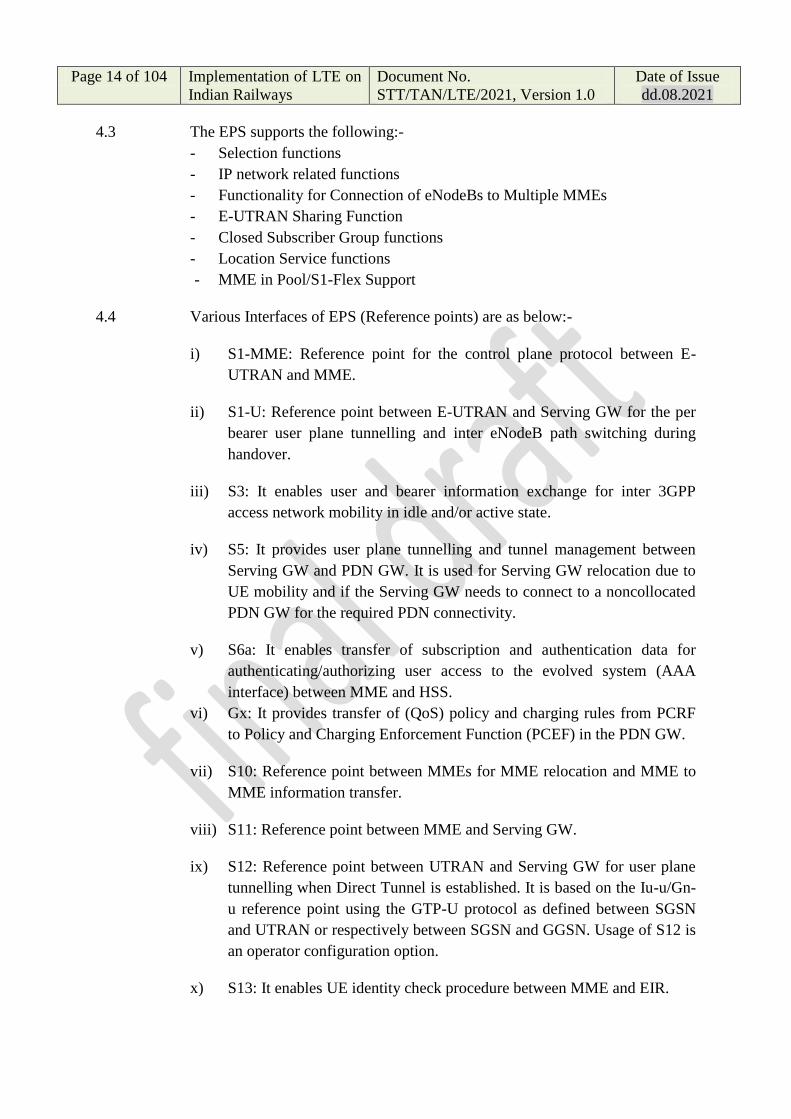
4.3 The EPS supports the following:-
- Selection functions
- IP network related functions
- Functionality for Connection of eNodeBs to Multiple MMEs
- E-UTRAN Sharing Function
- Closed Subscriber Group functions
- Location Service functions
- MME in Pool/S1-Flex Support
4.4 Various Interfaces of EPS (Reference points) are as below:-
i) S1-MME: Reference point for the control plane protocol between E-
UTRAN and MME.
ii) S1-U: Reference point between E-UTRAN and Serving GW for the per
bearer user plane tunnelling and inter eNodeB path switching during
handover.
iii) S3: It enables user and bearer information exchange for inter 3GPP
access network mobility in idle and/or active state.
iv) S5: It provides user plane tunnelling and tunnel management between
Serving GW and PDN GW. It is used for Serving GW relocation due to
UE mobility and if the Serving GW needs to connect to a noncollocated
PDN GW for the required PDN connectivity.
v) S6a: It enables transfer of subscription and authentication data for
authenticating/authorizing user access to the evolved system (AAA
interface) between MME and HSS.
vi) Gx: It provides transfer of (QoS) policy and charging rules from PCRF
to Policy and Charging Enforcement Function (PCEF) in the PDN GW.
vii) S10: Reference point between MMEs for MME relocation and MME to
MME information transfer.
viii) S11: Reference point between MME and Serving GW.
ix) S12: Reference point between UTRAN and Serving GW for user plane
tunnelling when Direct Tunnel is established. It is based on the Iu-u/Gn-
u reference point using the GTP-U protocol as defined between SGSN
and UTRAN or respectively between SGSN and GGSN. Usage of S12 is
an operator configuration option.
x) S13: It enables UE identity check procedure between MME and EIR.
Page 15 of 104 Implementation of LTE on
Indian Railways
Document No.
STT/TAN/LTE/2021, Version 1.0
Date of Issue
dd.08.2021
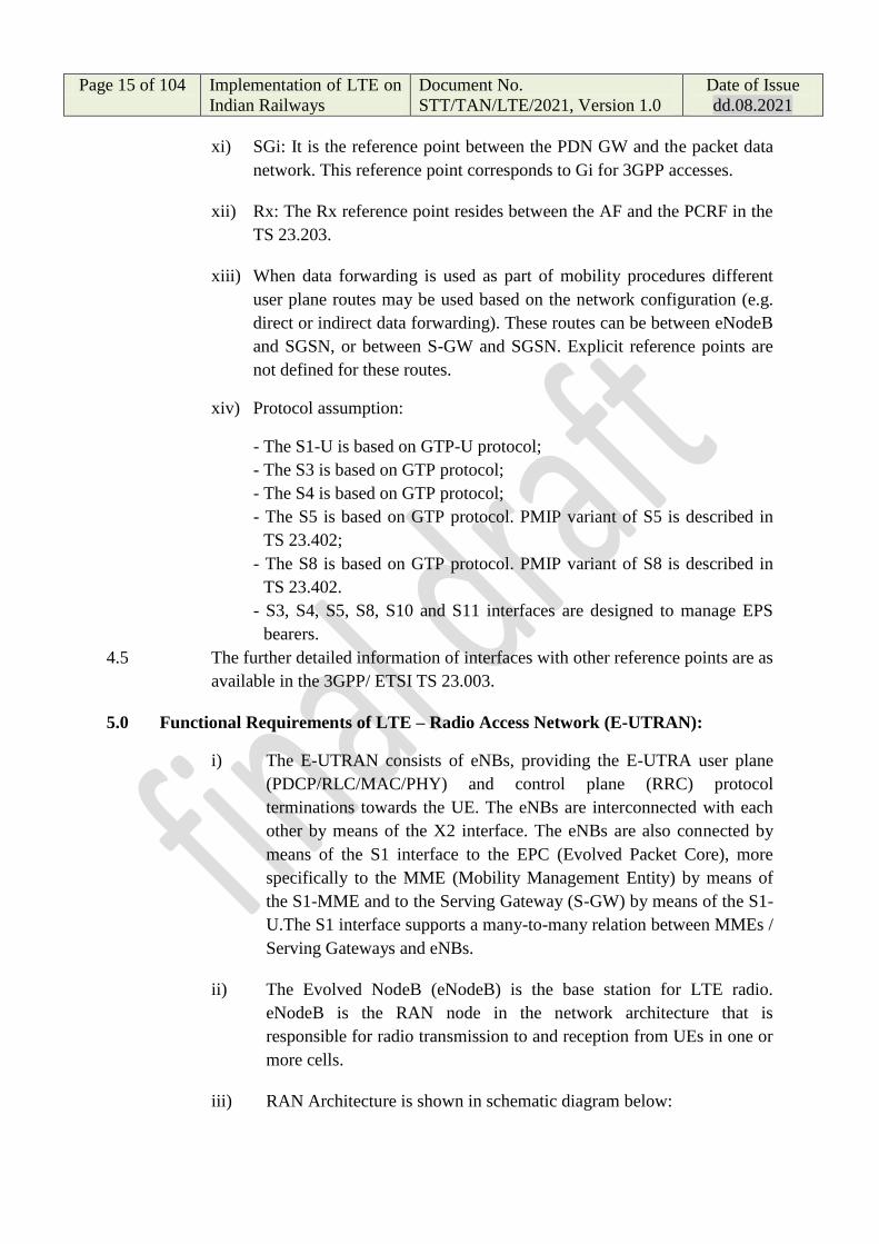
xi) SGi: It is the reference point between the PDN GW and the packet data
network. This reference point corresponds to Gi for 3GPP accesses.
xii) Rx: The Rx reference point resides between the AF and the PCRF in the
TS 23.203.
xiii) When data forwarding is used as part of mobility procedures different
user plane routes may be used based on the network configuration (e.g.
direct or indirect data forwarding). These routes can be between eNodeB
and SGSN, or between S-GW and SGSN. Explicit reference points are
not defined for these routes.
xiv) Protocol assumption:
- The S1-U is based on GTP-U protocol;
- The S3 is based on GTP protocol;
- The S4 is based on GTP protocol;
- The S5 is based on GTP protocol. PMIP variant of S5 is described in
TS 23.402;
- The S8 is based on GTP protocol. PMIP variant of S8 is described in
TS 23.402.
- S3, S4, S5, S8, S10 and S11 interfaces are designed to manage EPS
bearers.
4.5 The further detailed information of interfaces with other reference points are as
available in the 3GPP/ ETSI TS 23.003.
5.0 Functional Requirements of LTE – Radio Access Network (E-UTRAN):
i) The E-UTRAN consists of eNBs, providing the E-UTRA user plane
(PDCP/RLC/MAC/PHY) and control plane (RRC) protocol
terminations towards the UE. The eNBs are interconnected with each
other by means of the X2 interface. The eNBs are also connected by
means of the S1 interface to the EPC (Evolved Packet Core), more
specifically to the MME (Mobility Management Entity) by means of
the S1-MME and to the Serving Gateway (S-GW) by means of the S1-
U.The S1 interface supports a many-to-many relation between MMEs /
Serving Gateways and eNBs.
ii) The Evolved NodeB (eNodeB) is the base station for LTE radio.
eNodeB is the RAN node in the network architecture that is
responsible for radio transmission to and reception from UEs in one or
more cells.
iii) RAN Architecture is shown in schematic diagram below:

Page 16 of 104 Implementation of LTE on
Indian Railways
Document No.
STT/TAN/LTE/2021, Version 1.0
Date of Issue
dd.08.2021
eNB
MME / S-GW MME / S-GW
eNB
eNB
S1
S1
S1
S1
X2
X2X
2
E-UTRAN
Fig.-3: RAN Architecture
5.1 E-UTRAN Interface Requirements:
5.1.1 S1 Interface:
5.1.1.1 S1 User Plane Interface:
The S1 user plane interface (S1-U) is defined between the eNB and the S-GW.
The S1-U interface provides non guaranteed delivery of user plane PDUs
between the eNB and the S-GW. The transport network layer is built on IP
transport and GTP-U is used on top of UDP/IP to carry the user plane PDUs
between the eNB and the S-GW.
5.1.1.2 S1 Control Plane Interface:
The S1 control plane interface (S1-MME) is defined between the eNB and the
MME. The control plane protocol stack of the S1 interface is shown on Figure
19.2-1. The transport network layer is built on IP transport, similarly to the
user plane but for the reliable transport of signalling messages SCTP is added
on top of IP. The application layer signalling protocol is referred to as S1-AP
(S1 Application Protocol).
5.1.1.3 The following shall be the functions of S1 interface:-
i) E-RAB Service Management function:
- Setup, Modify, Release.
ii) Mobility Functions for UEs in ECM-CONNECTED:
- Intra-LTE Handover;
- Inter-3GPP-RAT Handover.

Page 17 of 104 Implementation of LTE on
Indian Railways
Document No.
STT/TAN/LTE/2021, Version 1.0
Date of Issue
dd.08.2021
iii) S1 Paging function:
iv) NAS Signalling Transport function;
v) LPPa Signalling Transport function;
vi) S1-interface management functions:
- Error indication;
- Reset.
vii) Network Sharing Function;
viii) Roaming and Access Restriction Support function;
ix) NAS Node Selection Function;
x) Initial Context Setup Function;
xi) UE Context Modification Function;
xii) UE Context Resume Function;
xiii) MME Load balancing Function;
xiv) Location Reporting Function;
xv) PWS (which includes ETWS and CMAS) Message Transmission
Function;
xvi) Overload function;
xvi) RAN Information Management Function;
xviii) Configuration Transfer Function;
xx) Trace function;
5.1.2 X2 Interface:
5.1.2.1 X2 user plane interface:
The X2 user plane interface (X2-U) is defined between eNBs. The X2-U
interface provides non guaranteed delivery of user plane PDUs. The transport
network layer is built on IP transport and GTP-U is used on top of UDP/IP to
carry the user plane PDUs.
5.1.2.1 X2 control plane interface:
The X2 control plane interface (X2-CP) is defined between two neighbour
eNBs. The control plane protocol stack of the X2 interface is shown on Figure
20.2-1 below. The transport network layer is built on SCTP on top of IP. The
application layer signalling protocol is referred to as X2-AP (X2 Application
Protocol).
5.1.2.3 The X2 interface specifications shall facilitate the following:
- inter-connection of eNBs supplied by different manufacturers;
- support of continuation between eNBs of the E-UTRAN services offered via
the S1 interface;
- separation of X2 interface Radio Network functionality and Transport
Network functionality to facilitate introduction of future technology.

Page 18 of 104 Implementation of LTE on
Indian Railways
Document No.
STT/TAN/LTE/2021, Version 1.0
Date of Issue
dd.08.2021
5.1.2.2 Functions of the X2 interface:-
The following shall be the functions of X2 interface:-
i) Intra LTE-Access-System Mobility Support for ECM-CONNECTED
UE:
- Context transfer from source eNB to target eNB;
- Control of user plane transport bearers between source eNB and
target eNB;
- Handover cancellation;
- UE context release in source eNB.
ii) Load Management
iii) Inter-cell Interference Coordination
- Uplink Interference Load Management;
iv) General X2 management and error handling functions:
- Error indication;
- Reset.
v) Application level data exchange between eNBs
vi) Trace functions
5.2 E-UTRAN Functional Requirements:
5.2.1 Functions of eNodeB:
The eNodeB/ eNB shall support the functions as per 3GPP specifications
including the following:
5.2.1.1 Functions for Radio Resource Management: Radio Bearer Control, Radio
Admission Control, Connection Mobility Control, Dynamic allocation of
resources to UEs in both uplink and downlink (scheduling);
5.2.1.2 IP header compression and encryption of user data stream;
5.2.1.3 Selection of an MME at UE attachment when no routing to an MME can be
determined from the information provided by the UE;
5.2.1.4 Routing of User Plane data towards Serving Gateway;
5.2.1.5 Scheduling and transmission of paging messages (originated from the MME);
5.2.1.6 Scheduling and transmission of broadcast information (originated from the
MME or O&M);
5.2.1.7 Measurement and measurement reporting configuration for mobility and
scheduling;

Page 19 of 104 Implementation of LTE on
Indian Railways
Document No.
STT/TAN/LTE/2021, Version 1.0
Date of Issue
dd.08.2021
5.2.1.8 Scheduling and transmission of PWS (which includes ETWS and CMAS)
messages (originated from the MME);
5.2.1.9 CSG handling;
5.2.2 E-UTRAN Physical Layer Requirements:
The E-UTRAN shall support 3GPP Physical Layer (Layer 1) functional
requirements.
5.2.2.1 The E-UTRAN (eNodeB) shall support the following Layer 1 requirements:-
i) Error detection on the transport channel and indication to higher layers
ii) FEC encoding/decoding of the transport channel
iii) Hybrid ARQ soft-combining
iv) Rate matching of the coded transport channel to physical channels
v) Mapping of the coded transport channel onto physical channels
vi) Power weighting of physical channels
vii) Modulation and demodulation of physical channels
viii) Frequency and time synchronisation
ix) Radio characteristics measurements and indication to higher layers
x) Multiple Input Multiple Output (MIMO) antenna processing
xi) Transmit Diversity (TX diversity)
xii) RF processing.
5.2.2.2 The multiple access scheme for the LTE physical layer is based on Orthogonal
Frequency Division Multiplexing (OFDM) with a cyclic prefix (CP) in the
downlink, and on Single-Carrier Frequency Division Multiple Access
(SCFDMA) with a cyclic prefix in the uplink.
5.2.2.3 To support transmission in paired and unpaired spectrum, two duplex modes
are supported: Frequency Division Duplex (FDD), supporting full duplex and
half duplex operation, and Time Division Duplex (TDD).
5.2.2.4 The modulation schemes supported in the uplink are QPSK, 16QAM and
64QAM and in downlink are QPSK, 16QAM, 64QAM and 256 QAM.
5.2.2.5 i) The physical channels defined in the downlink are:
- the Physical Downlink Shared Channel (PDSCH),
- the Physical Multicast Channel (PMCH),
- the Physical Downlink Control Channel (PDCCH),
- the Physical Broadcast Channel (PBCH),
- the Physical Control Format Indicator Channel (PCFICH)
- and the Physical Hybrid ARQ Indicator Channel (PHICH).

Page 20 of 104 Implementation of LTE on
Indian Railways
Document No.
STT/TAN/LTE/2021, Version 1.0
Date of Issue
dd.08.2021
ii) The physical channels defined in the uplink are:
- the Physical Random Access Channel (PRACH),
- the Physical Uplink Shared Channel (PUSCH),
- and the Physical Uplink Control Channel (PUCCH).
iii) In addition, signals are defined as reference signals, primary and
secondary synchronization signals.
5.2.2.6 System shall also support the following procedures:-
a. Synchronisation procedures, including cell search procedure and
timing synchronisation;
b. Power control procedure;
c. Random access procedure;
d. Physical downlink shared channel related procedures, including CQI
reporting and MIMO feedback;
e. Physical uplink shared channel related procedures, including UE
sounding and HARQ ACK/NACK detection;
f. Physical shared control channel procedures, including assignment of
shared control channels;
g. Physical multicast channel related procedures
5.2.2.9 E-UTRAN shall support physical Layer measurements which include
measurements for intra- and inter-frequency handover, inter RAT handover,
timing measurements and measurements for RRM and in support for
positioning.
5.2.3 E-UTRAN Layer 2 Requirements:
5.2.3.1 The E-UTRAN shall support 3GPP Layer 2 sublayers Medium Access Control
(MAC), Radio Link Control (RLC) and Packet Data Convergence Protocol
(PDCP) for downlink and uplink.
5.2.3.2 The main services and functions of the MAC sublayer include:
a. mapping between logical channels and transport channels;
b. Multiplexing/demultiplexing of MAC SDUs belonging to one or different
logical channels into/from transport blocks (TB) delivered to/from the
physical layer on transport channels
c. scheduling information reporting;
d. Error correction through HARQ;
e. Priority handling between logical channels of one UE;
f. Priority handling between UEs by means of dynamic scheduling;
g. MBMS service identification for important pre identified users ;

Page 21 of 104 Implementation of LTE on
Indian Railways
Document No.
STT/TAN/LTE/2021, Version 1.0
Date of Issue
dd.08.2021
h. Transport format selection;
i. Padding.
5.2.3.3 The E-UTRAN shall support Control Channels i.e. Broadcast Control Channel
(BCCH), Paging Control Channel (PCCH), Common Control Channel
(CCCH), Multicast Control Channel (MCCH) and Dedicated Control Channel
(DCCH). The Traffic Channels supported shall be Dedicated Traffic Channel
(DTCH) and Multicast Traffic Channel (MTCH).
5.2.3.5 The main services and functions of the RLC sublayer include:-
a. Transfer of upper layer PDUs;
b. Error Correction through ARQ (only for AM data transfer);
c. Concatenation, segmentation and reassembly of RLC SDUs (only for UM
and AM data transfer);
d. Re-segmentation of RLC data PDUs (only for AM data transfer);
e. Reordering of RLC data PDUs (only for UM and AM data transfer);
f. Duplicate detection (only for AM data transfer);
g. Protocol error detection (only for AM data transfer);
h. RLC SDU discard (only for UM and AM data transfer);
i. RLC re-establishment.
5.2.3.6 PDCP Sub layer: The main services and functions of the PDCP sublayer for
the user plane include:-
a. Header compression and decompression: ROHC only;
b. Transfer of user data;
c. In-sequence delivery of upper layer PDUs at PDCP re-establishment
procedure for RLC AM;
d. Duplicate detection of lower layer SDUs at PDCP re-establishment
procedure for RLC AM;
e. Retransmission of PDCP SDUs at handover for RLC AM;
f. Ciphering and deciphering;
g. Timer-based SDU discard in uplink;
5.2.4 E-UTRAN Layer 3 Requirements:
The E-UTRAN shall support 3GPP Layer 3 (RRC) functional requirements.
5.2.4.1 The main services and functions of the Radio Resource Control (RRC)
include:
i) Broadcast of System Information related to the non-access stratum
(NAS);
ii) Broadcast of System Information related to the access stratum (AS);

Page 22 of 104 Implementation of LTE on
Indian Railways
Document No.
STT/TAN/LTE/2021, Version 1.0
Date of Issue
dd.08.2021
iii) Paging;
iv) Establishment, maintenance and release of an RRC connection
between the UE and E-UTRAN including Allocation of temporary
identifiers between UE and E-UTRAN, Configuration of signalling
radio bearer(s) for RRC connection and Low priority SRB and high
priority SRB.
v) Security functions including key management;
vi) Establishment, configuration, maintenance and release of point to point
Radio Bearers;
vii) Mobility functions including: UE measurement reporting and control
of the reporting for inter-cell and inter-RAT mobility; Handover; UE
cell selection and reselection and control of cell selection and
reselection; Context transfer at handover.
viii) Notification for MBMS services;
ix) Establishment, configuration, maintenance and release of Radio
Bearers for MBMS services;
x) QoS management functions;
xi) UE measurement reporting and control of the reporting;
xii) NAS direct message transfer to/from NAS from/to UE.
5.3 System Specification of eNodeB:
5.3.1 The system specification of eNodeB shall be as per the following:-
S. No. Parameter Standard
Transmitter
As per 3GPP/ ETSI TS
36.104
i) Base station output power
ii) Adjacent Channel Leakage power Ratio
(ACLR)
iii) Transmitter spurious emissions
iv) Operating band unwanted emissions
v) Transmitter inter modulation
vi) Frequency Error
Receiver
As per 3GPP/ETSI TS
36.104
i) Reference sensitivity level
ii) Dynamic Range
iii) Adjacent Channel Selectivity (ACS)
and narrow-band blocking
iv) Receiver spurious emissions
v) Receiver inter modulation
Page 23 of 104 Implementation of LTE on
Indian Railways
Document No.
STT/TAN/LTE/2021, Version 1.0
Date of Issue
dd.08.2021
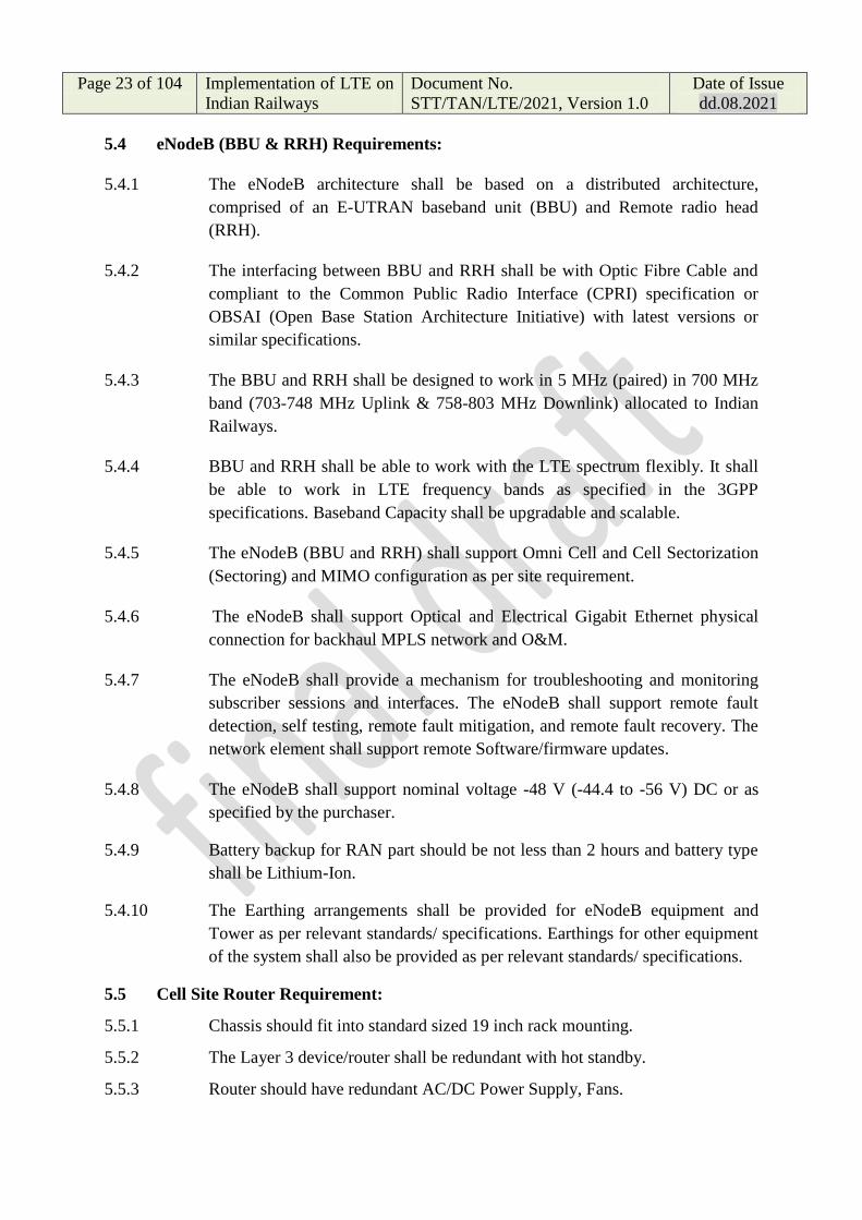
5.4 eNodeB (BBU & RRH) Requirements:
5.4.1 The eNodeB architecture shall be based on a distributed architecture,
comprised of an E-UTRAN baseband unit (BBU) and Remote radio head
(RRH).
5.4.2 The interfacing between BBU and RRH shall be with Optic Fibre Cable and
compliant to the Common Public Radio Interface (CPRI) specification or
OBSAI (Open Base Station Architecture Initiative) with latest versions or
similar specifications.
5.4.3 The BBU and RRH shall be designed to work in 5 MHz (paired) in 700 MHz
band (703-748 MHz Uplink & 758-803 MHz Downlink) allocated to Indian
Railways.
5.4.4 BBU and RRH shall be able to work with the LTE spectrum flexibly. It shall
be able to work in LTE frequency bands as specified in the 3GPP
specifications. Baseband Capacity shall be upgradable and scalable.
5.4.5 The eNodeB (BBU and RRH) shall support Omni Cell and Cell Sectorization
(Sectoring) and MIMO configuration as per site requirement.
5.4.6 The eNodeB shall support Optical and Electrical Gigabit Ethernet physical
connection for backhaul MPLS network and O&M.
5.4.7 The eNodeB shall provide a mechanism for troubleshooting and monitoring
subscriber sessions and interfaces. The eNodeB shall support remote fault
detection, self testing, remote fault mitigation, and remote fault recovery. The
network element shall support remote Software/firmware updates.
5.4.8 The eNodeB shall support nominal voltage -48 V (-44.4 to -56 V) DC or as
specified by the purchaser.
5.4.9 Battery backup for RAN part should be not less than 2 hours and battery type
shall be Lithium-Ion.
5.4.10 The Earthing arrangements shall be provided for eNodeB equipment and
Tower as per relevant standards/ specifications. Earthings for other equipment
of the system shall also be provided as per relevant standards/ specifications.
5.5 Cell Site Router Requirement:
5.5.1 Chassis should fit into standard sized 19 inch rack mounting.
5.5.2 The Layer 3 device/router shall be redundant with hot standby.
5.5.3 Router should have redundant AC/DC Power Supply, Fans.

Page 24 of 104 Implementation of LTE on
Indian Railways
Document No.
STT/TAN/LTE/2021, Version 1.0
Date of Issue
dd.08.2021
5.5.4 Should support MPLS and VLAN functionality
5.5.5 Router should support non-blocking capacity of minimum 120 Gbps. Layer-3
devices shall be router or layer-3 switch and constitute the backbone 10 Gbps
of links connected to Indian Railway Network.
5.5.6 The router should be equipped with 6 x 10G interfaces with 4 x 10G SR + 2 x
10G LR. Additionally, it should also be equipped with 4 x 1G Base-T
interfaces
5.5.7 Cell Site Router should have following functionality / features:-
i) Router should support LAG & multi-chassis LAG for aggregation of
links across two chassis.
ii) Router must support MPLS LDP, RSVP-TE, LDP FRR, BGP Labeled
Unicast, BGP PIC, P2P LSP, P2MP LSP
iii) Router should support MPLSVPN, L3 VPN, L2VPN/VPLS &
EVPN/Pesudowire.
iv) Multicast: The router should support Protocol Independent Multicast
(PIM) & IGMP v1, v2 and v3
v) The router should support Protocol Independent Multicast (PIM) &
IGMP v1, v2 and v3.
vi) The proposed router should support synchronization using IEEE
1588v2 and Sync E and must be configured with the required licenses
from Day 1.
vii) Router should support HQOS on all kind of interface.
viii) Router should support MPLS OAM, Ethernet OAM protocols - CFM
(IEEE 802.1ag), Link OAM (IEEE 802.3ah) and ITU Y.1731,
TWAMP, SAA or equivalent.
ix) The proposed router should provide SNMP based Traps and Alarms to
the configured EMS/NMS. SNMP v1, v2 and v3 should be supported.
The router should support SNMP/NETCONF/RESTCONF/Yang /
JSON / GPB / XML for network management & provisioning
functions.
x) Device should have functionality for Latency, Packet drop, Jitter etc.
xi) Layer 3 device should support following SNMP traps or Syslog: -
a. Interface UP & Down;
b. Optical power SFP threshold alarms;
c. ERPS Ring Protection feature to be supported;
d. LLDP table changes;
e. Power Supply (Primary and Secondary) down and Up alarms in case of
redundant power supply;

Page 25 of 104 Implementation of LTE on
Indian Railways
Document No.
STT/TAN/LTE/2021, Version 1.0
Date of Issue
dd.08.2021
f. Threshold traps like CPU, Chassis Temperature and Memory; and
g. CFM and LFM alarms.
xii) Should support following security features as a minimum.
a. Web Management (HTTPS)/SSH;
b. Broadcast/Multicast/Unicast Storm Control; and
c. DoS Attack Prevention.
6.0 Functional Requirements of Evolved Packet Core (EPC):
The Evolved packet Core (EPC) is the Core network of LTE system composed
of four network elements: Mobility Management Entity (MME), Home
Subscriber Server (HSS), Serving Gateway (Serving GW) and Packet Data
Network Gateway (PDN GW).
6.1 Mobility Management Entity (MME):
The MME deals with the control plane. It handles the signalling related to
mobility and security for E-UTRAN access. The MME is responsible for the
tracking and the paging of UE in idle-mode. It is the termination point of the
Non-Access Stratum (NAS).
6.1.1 MME shall support the following functions:-
i) NAS signalling;
ii) NAS signalling security;
iii) Inter CN node signalling for mobility between 3GPP access networks
(terminating S3);
iv) UE Reachability in ECM-IDLE state (including control and execution of
paging retransmission);
v) Tracking Area list management;
vi) Mapping from UE location (e.g. TAI) to time zone, and signalling a UE
time zone change associated with mobility;
vii) PDN GW and Serving GW selection;
viii) MME selection for handovers with MME change;
ix) SGSN selection for handovers to 2G access networks;
x) Roaming (S6a towards home HSS);
xi) Authentication;
xii) Authorization;
xiii) Bearer management functions including dedicated bearer establishment;
xiv) Warning message transfer function (including selection of appropriate
eNodeB);
Page 26 of 104 Implementation of LTE on
Indian Railways
Document No.
STT/TAN/LTE/2021, Version 1.0
Date of Issue
dd.08.2021
xv) UE Reachability procedures.
6.2 Serving Gateway (S-GW):
6.2.1 The Serving GW is the gateway which terminates the user plane interface
towards E-UTRAN (except when user data is transported using the Control
Plane CIoT EPS Optimisation). For each UE associated with the EPS, at a
given point of time, there is a single Serving GW.
6.2.3 The functions of the Serving GW, the GTP-based S5/S8, include:
i) the local Mobility Anchor point for inter-eNodeB handover;
ii) sending of one or more "end marker" to the source eNodeB, source
SGSN immediately after switching the path during inter-eNodeB and
inter-RAT handover, especially to assist the reordering function in
eNodeB.
iii) Mobility anchoring for inter-3GPP mobility (terminating S4 and
relaying the traffic between 2Gsystem and PDN GW);
iv) ECM-IDLE mode downlink packet buffering and initiation of network
triggered service request procedure;
v) Packet routing and forwarding;
vi) Transport level packet marking in the uplink and the downlink, e.g.
setting the DiffServ Code Point, based on the QCI of the associated
EPS bearer;
6.2.4 In addition to the functions mentioned above, the Serving GW includes the
following functionality:
i) A local non-3GPP anchor for the case of roaming when the non-3GPP
IP accesses connected to the VPLMN.
ii) Event reporting (change of RAT, etc.) to the PCRF.
iii) Uplink and downlink bearer binding towards 3GPP accesses as
defined in TS 23.203.
iv) Uplink bearer binding verification with packet dropping of
"misbehaving UL traffic".
v) .
vi) Decide if packets are to be forwarded (uplink towards PDN or
downlink towards UE) or if they are locally destined to the S-GW (e.g.
Router Solicitation).
6.2.2 The PDN GW and the Serving GW may be implemented in one physical node
or separated physical nodes.
Page 27 of 104 Implementation of LTE on
Indian Railways
Document No.
STT/TAN/LTE/2021, Version 1.0
Date of Issue
dd.08.2021
6.3 Packet Data Network Gateway (PDN GW):
PDN GW functionality is described in TS 23.401 for 3GPP accesses connected
to the EPC via GTP-based S5/S8 interface. The PDN GW supports
functionality specified in TS 23.401 that GTP-based S5/S8 interfaces also for
access to EPC via non-3GPP accesses. 6.3.1 The PDN GW is the gateway
which terminates the SGi interface towards the PDN. If a UE is accessing
multiple PDNs, there may be more than one PDN GW for that UE
6.3.2 PDN GW functions include the GTP-based -based S5/S8:
i) Per-user based packet filtering (by e.g. deep packet inspection);
ii) UE IP address allocation;
iii) Transport level packet marking in the uplink and downlink, e.g.
setting the DiffServ Code Point, based on the QCI of the associated
EPS bearer;
iv) UL and DL service level gating control as defined in TS 23.203 ;
v) UL and DL service level rate enforcement as defined in TS 23.203
(e.g. by rate policing/shaping per SDF);
vi) UL and DL rate enforcement based on APN-AMBR
(e.g. by rate policing/shaping per aggregate of traffic of all SDFs of the same
APN that are associated with Non- GBR QCIs);
vii) DL rate enforcement based on the accumulated MBRs of the
aggregate of SDFs with the same GBR QCI (e.g. by rate
policing/shaping);
viii) DHCPv4 (server and client) and DHCPv6 (client and server)
functions;
ix) packet screening.
6.3.3 Additionally the PDN GW includes the following functions for the GTP-based
S5/S8:
i) UL and DL bearer binding as defined in TS 23.203;
ii) UL bearer binding verification as defined in TS 23.203;
iv) Accounting per UE and bearer.
6.3.4 The P-GW provides PDN connectivity to GERAN UEs and E-UTRAN
capable UEs using any of E-UTRAN or GERAN. The P- GW provides PDN
connectivity to E-UTRAN capable UEs using E-UTRAN only over the S5/S8
interface.
PDN GW functionality is described in TS 23.401 for 3GPP accesses
connected to the EPC via GTP-based S5/S8 interface.

Page 28 of 104 Implementation of LTE on
Indian Railways
Document No.
STT/TAN/LTE/2021, Version 1.0
Date of Issue
dd.08.2021
6.3.6 The PDN GW and the Serving GW may be implemented in one physical node
or separated physical nodes.
6.4 Home Subscriber Server (HSS):
6.4.1 The HSS (for Home Subscriber Server) is a database that contains user-related
and subscriber-related information. It is the entity containing the subscription-
related information to support the network entities actually handling
calls/sessions. It also provides support functions in mobility management, call
and session setup, user authentication and access authorization. The HSS shall
be broadly based on 3GPP specification.
6.4.2 A Home Network may contain one or several HSSs: it depends on the number
of mobile subscribers, on the capacity of the equipment and on the organisation
of the network. The HSS provides support to the call control servers in order to
complete the routing/roaming procedures by solving authentication,
authorisation, naming/addressing resolution, location dependencies, etc.
6.4.3 The HSS is responsible for holding the following user related information:
- User Identification, Numbering and addressing information;
- User Security information: Network access control information for
authentication and authorization;
- User Location information at inter-system level: the HSS supports the
user registration, and stores inter-system location information, etc.;
- User profile information.
6.4.4 The HSS also generates User Security information for mutual authentication,
communication integrity check and ciphering.
6.4.5 Based on this information, the HSS also is responsible to support the call
control and session management entities of the different Domains and
Subsystems
6.4.6 The HSS may integrate heterogeneous information, and enable enhanced
features in the core network to be offered to the application & services
domain, at the same time hiding the heterogeneity.
6.4.7 The HSS shall support the following functionalities:
6.4.7.1 (#deleted)
6.4.7.2 The subset of the HLR/AUC functionality required by the PS Domain (GPRS
and EPC).

Page 29 of 104 Implementation of LTE on
Indian Railways
Document No.
STT/TAN/LTE/2021, Version 1.0
Date of Issue
dd.08.2021
6.4.7.3 The subset of the HLR/AUC functionality required by the CS Domain, if it is
desired to enable subscriber access to the CS Domain or to support roaming to
legacy GSM CS Domain networks.
6.4.8. The Home Location Register (HLR):
The HLR can be considered a subset of the HSS or separate logical function
that holds the following functionality:
6.4.8.1 The functionality required to provide support to PS Domain entities such as
the SGSN, MME and GGSN, through the Gr, S6a, S6dand Gc interfaces and
the 3GPP AAA Server for EPS in case of non-3GPP access via SWx and for
the I-WLAN through the D'/Gr' interface. It is needed to enable subscriber
access to the PS Domain services.
6.4.8.2 The functionality required to provide support to CS Domain entities such as
the MSC/MSC server and GMSC/GMSC server, through the C and D
interfaces. It is needed to enable subscriber access to the CS Domain services
and to support roaming to legacy GSM CS Domain networks.
6.4.9 The Authentication Centre (AuC):
The AuC can be considered a subset of the HSS/HLR that holds the following
functionality for the CS Domain and PS Domain:
6.4.9.1 The AuC is associated with an HLR and stores an identity key for each mobile
subscriber registered with the associated HLR. This key is used to generate
security data for each mobile subscriber:
i) Data which are used for mutual authentication of the International
Mobile Subscriber Identity (IMSI) and the network;
ii) a key used to check the integrity of the communication over the radio
path between the mobile station and the network;
iii) a key used to cipher communication over the radio path between the
mobile station and the network.
6.4.9.2 The AuC communicates only with its associated HLR over a non-standardised
interface denoted the H-interface. The HLR requests the data needed for
authentication and ciphering from the AuC via the H-interface, stores them
and delivers them to the VLR and SGSN and MME which need them to
perform the security functions for a mobile station.
6.4.10 HSS logical functions:
HSS logical functionality shall be as per the following:-

Page 30 of 104 Implementation of LTE on
Indian Railways
Document No.
STT/TAN/LTE/2021, Version 1.0
Date of Issue
dd.08.2021
6.4.10.1 Mobility Management:
This function supports the user mobility through CS Domain and PS Domain
subsystem.
6.4.10.2 Call and/or session establishment support:
The HSS supports the call and/or session establishment procedures in CS
Domain and PS Domain subsystem. For terminating traffic, it provides
information on which call and/or session control entity currently hosts the
user.
6.4.10.3 User security information generation:
6.4.10.3.1 The HSS generates user authentication, integrity and ciphering data for the CS
and PS Domains subsystem. User security support
6.4.10.3.2 The HSS supports the authentication procedures to access CS Domain and PS
Domain subsystem services by storing the generated data for authentication,
integrity and ciphering and by providing these data to the appropriate entity in
the CN. (i.e. MSC/VLR, SGSN, MME, 3GPP AAA Server or CSCF).
6.4.10.4 User identification handling:
The HSS/ HLR provides the appropriate relations among all the identifiers
uniquely determining the user in the system: CS Domain and PS Domain
subsystem.
6.4.10.5 Access authorisation:
The HSS/HLR authorises the user for mobile access when requested by the
MSC/VLR, SGSN, MME, 3GPP AAA Server or CSCF, by checking that the
user is allowed to roam to that visited network.
6.4.10.6 Service authorisation support:
The HSS provides basic authorisation for MT call/session establishment and
service invocation. Besides, the HSS updates the appropriate serving entities
(i.e., MSC/VLR, SGSN, MME, 3GPP AAA Server, CSCF) with the relevant
information related to the services to be provided to the user.
6.4.10.7 Service Provisioning Support:
6.4.10.7.1 The HSS/ HLR provides access to the service profile data for use within the
CS Domain and PS Domain.
6.4.10.8 (#Deleted)
Page 31 of 104 Implementation of LTE on
Indian Railways
Document No.
STT/TAN/LTE/2021, Version 1.0
Date of Issue
dd.08.2021
6.5 Policy and Charging Rule Function (PCRF) :
6.5.1 PCRF is the policy and charging control element. In non-roaming scenario,
there is only a single PCRF in the HPLMN associated with one UE's IP-CAN
session. The PCRF terminates the Rx interface and the Gx interface.
6.5.2 High Level Requirements:
6.5.2.1 It shall be possible for the PCC architecture to base decisions upon
subscription information.
6.5.2.4 The PCC architecture shall discard packets that don't match any service data
flow filter of the active PCC rules. It shall also be possible for the operator to
define PCC rules, with wild-carded service data flow filters, to allow for the
passage and charging for packets that do not match any service data flow filter
of any other active PCC rules.
6.5.2.6 The PCC architecture shall have a binding method that allows the unique
association between service data flows and their IP-CAN bearer.
6.5.2.8 A PCC rule may be predefined or dynamically provisioned at establishment
and during the lifetime of an IP-CAN session. The latter is referred to as a
dynamic PCC rule.
6.5.2.10 It shall be possible to take a PCC rule into service, and out of service, at a
specific time of day, without any PCC interaction at that point in time.
6.5.2.11 PCC shall be enabled on a per PDN basis (represented by an access point and
the configured range of IP addresses) at the PCEF. It shall be possible for the
operator to configure the PCC architecture to perform charging control, policy
control or both for a PDN access.
6.5.2.13 The PCC architecture shall allow the resolution of conflicts which would
otherwise cause a subscriber's Subscribed Guaranteed Bandwidth QoS to be
exceeded.
6.5.2.16 It shall be possible with the PCC architecture, in real-time, to monitor the
overall amount of resources that are consumed by a user.
6.5.3 Policy Control Functionalities:
6.5.3.1 Policy control comprises functionalities for:
i) Binding, i.e. the generation of an association between a service data flow
and the IP-CAN bearer transporting that service data flow;

Page 32 of 104 Implementation of LTE on
Indian Railways
Document No.
STT/TAN/LTE/2021, Version 1.0
Date of Issue
dd.08.2021
ii) Gating control, i.e. the blocking or allowing of packets, belonging to a
service data flow or specified by an application identifier, to pass
through to the desired endpoint;
iii) Event reporting, i.e. the notification of and reaction to application events
to trigger new behaviour in the user plane as well as the reporting of
events related to the resources in the GW (PCEF);
iv) QoS control, i.e. the authorisation and enforcement of the maximum
QoS that is authorised for a service data flow, an Application identified
by application identifier or an IP-CAN bearer;
v) Redirection, i.e. the steering of packets, belonging to an application
defined by the application identifier to the specified redirection address;
vi) IP-CAN bearer establishment for IP-CANs that support network initiated
procedures for IP-CAN bearer establishment.
6.5.3.3 The enforcement of the authorized QoS of the IP-CAN bearer may lead to a
downgrading or upgrading of the requested bearer QoS by the GW(PCEF) as
part of a UE-initiated IP-CAN bearer establishment or modification.
Alternatively, the enforcement of the authorised QoS may, depending on
operator policy and network capabilities, lead to network initiated IP-CAN
bearer establishment or modification. If the PCRF provides authorized QoS for
both, the IP-CAN bearer and PCC rule(s), the enforcement of authorized QoS
of the individual PCC rules shall take place first.
6.5.3.4 QoS authorization information may be dynamically provisioned by the PCRF
or, it can be a pre-defined PCC rule in the PCEF. In case the PCRF provides
PCC rules dynamically, authorised QoS information for the IP-CAN bearer
(combined QoS) may be provided. For a predefined PCC rules within the
PCEF the authorized QoS information shall take affect when the PCC rule is
activated. The PCEF shall combine the different sets of authorized QoS
information, i.e. the information received from the PCRF and the information
corresponding to the predefined PCC rules. The PCRF shall know the
authorized QoS information of the predefined PCC rules and shall take this
information into account when activating them. This ensures that the combined
authorized QoS of a set of PCC rules that are activated by the PCRF is within
the limitations given by the subscription and operator policies regardless of
whether these PCC rules are dynamically provided, predefined or both.
6.5.3.5 For policy control, the AF interacts with the PCRF and the PCRF interacts
with the PCEF as instructed by the AF. For certain events related to policy
control, the AF shall be able to give instructions to the PCRF to act on its own,
i.e. based on the service information currently available.

Page 33 of 104 Implementation of LTE on
Indian Railways
Document No.
STT/TAN/LTE/2021, Version 1.0
Date of Issue
dd.08.2021
6.5.3.6 For policy control, the AF interacts with the PCRF and the PCRF interacts
with the PCEF as instructed by the AF. For certain events related to policy
control, the AF shall be able to give instructions to the PCRF to act on its own,
i.e. based on the service information currently available. The following events
are subject to instructions from the AF:
i) The authorization of the service based on incomplete service
information;
ii) The immediate authorization of the service;
iii) The gate control (i.e. whether there is a common gate handling per AF
session or an individual gate handling per AF session component
required);
iv) The forwarding of IP-CAN bearer level information or events:
- Type of IP-CAN ;
- Transmission resource status (established/released/lost);
-
6.5.3.7 To enable the binding functionality, the UE and the AF shall provide all
available flow description information (e.g. source and destination IP address
and port numbers and the protocol information). The UE shall use the traffic
mapping information to indicate downlink and uplink IP flows.
7.0 Communication Requirement - Future Railway Mobile Communication
System (FRMCS):-
7.1 The communication requirement of LTE shall be complying to “Future
Railway Mobile Communication System - User Requirements Specification”,
released by the International Union of Railways (UIC).
7.2 The General Communication Requirements for Voice like One-to-one calls,
Caller identity display, Restriction of display of called/calling user, Call
forwarding, Call waiting, Call hold, Call barring, and for Data like bearer
services for telemetry, messaging, train control applications, information
exchange and general data applications are available in the commercial LTE
networks based on the LTE technology releases.
7.3 Users in FRMCS:
The following users are those identified to be users within this document and
may not be necessarily conclusive within FRMCS:-
• Driver(s)
• Controller(s)
• Train staff:
o Train conductor(s)

Page 34 of 104 Implementation of LTE on
Indian Railways
Document No.
STT/TAN/LTE/2021, Version 1.0
Date of Issue
dd.08.2021
o Catering staff
o Security staff
• Trackside staff:
o Trackside maintenance personnel
o Shunting team member(s)
• Railway staff (excl. all of above):
o Engine scheduler(s)
o RU operator(s)
o Catering scheduler(s)
o IM operator(s)
o Engineering personnel
• Station manager(s)
o Station personnel
o Depot personnel
o Etc.
• Member of the public:
o Passengers (on trains, on platforms, at stations, etc.)
o Other persons (on platforms, at level crossings, etc.)
• Systems:
o ATC on-board system
o ATO on-board system
o On-board system
o Ground system
o Trackside warning system
o Trackside system
o Sensors along trackside
o Trackside elements controlling entities (such as, for example, for
level crossings)
o Applications (such as, for example, those for monitoring lone
workers, for remote controlling of elements)
• Network operator
• Public emergency operator
7.3 (I) Fundamental Principles:-
i) The FRMCS shall satisfy the communication needs of the railway
operation.
ii) FRMCS shall support the applications independently of the used
FRMCS networks and radio access technologies by any of the users.
Transition of a user to or from other FRMCS networks or radio access
technologies shall not lead to interruption of the usage of the applications.
iii) The FRMCS shall place the human being at the centre of the design.

Page 35 of 104 Implementation of LTE on
Indian Railways
Document No.
STT/TAN/LTE/2021, Version 1.0
Date of Issue
dd.08.2021
iv) The FRMCS shall support the application of the harmonised
operational rules and principles where available.
v) The FRMCS shall support the exchange of information and
performance of actions without the manual assistance of humans (machine to
machine communication) both for operational and maintenance purposes.
vi) The FRMCS shall mitigate the risk of miscommunication.
vii) The FRMCS shall be cost effective.
viii) The FRMCS shall provide precautionary measures to prevent
unauthorised access.
7.4 Communication requirements:-
• Critical: applications that is essential for train movements and safety or a
legal obligation, such as emergency communications, shunting, presence,
trackside maintenance, ATC, etc.
• Performance: applications that help to improve the performance of the
railway operation, such as train departure, telemetry, etc.
• Business: applications that support the railway business operation in
general, such as wireless internet, etc.
7.5 The UIC document “Future Railway Mobile Communication System - User
Requirements Specification”, shall be referred for the following sub-sections
for communication requirements:-
7.6 FRMCS Clause 5: Critical Communication Applications
5.1 On-train outgoing voice communication from the driver towards the
controller(s) of the train:
5.2 On-train incoming voice communication from the controller towards a driver:
5.3 Multi-train voice communication for drivers including ground user(s):
5.4 Banking voice communication:
5.5 Trackside maintenance voice communication:
5.6 Shunting voice communication:
5.7 Public emergency call:
5.8 Ground to ground voice communication:
5.9 Automatic train control communication:
5.10 Automatic train operation communication:
5.11 Data communication for Possession management:
5.12 Trackside maintenance warning system communication:
5.13 Remote control of engines communication:
5.14 Monitoring and control of critical infrastructure:
5.15 Railway emergency communication:
5.16 On-train safety device to ground communication:
Page 36 of 104 Implementation of LTE on
Indian Railways
Document No.
STT/TAN/LTE/2021, Version 1.0
Date of Issue
dd.08.2021
5.17 Public train emergency communication:
5.18 Working alone:
5.19 Voice Recording and access to the recorded data:
5.20 Data recording and access:
5.21 Shunting data communication:
5.22 Train integrity monitoring data communication:
5.23 Public emergency warning:
5.24 On-train outgoing voice communication from train staff towards a ground user:
5.25 On-train incoming voice communication from a ground user towards train staff:
5.26 Railway staff emergency communication:
5.27 Critical Real time video:
5.28 Critical Advisory Messaging services- safety related:
5.29 Virtual Coupling data communication:
5.30 Train parking protection:
7.7 FRMCS Clause 6: Performance Communication Applications
6.3 Multi-train voice communication for drivers excluding ground user(s):
6.4 On-train voice communication:
6.5 Lineside telephony:
6.6 On-train voice communication towards passengers (public address):
6.7 Station public address:
6.8 Communication at stations and depots:
6.9 On-train telemetry communications:
6.10 Infrastructure telemetry communications:
6.11 On-train remote equipment control:
6.12 Monitoring and control of non-critical infrastructure:
6.13 Non-critical Real time video:
6.14 Wireless on-train data communication for train staff:
6.15 Wireless data communication for railway staff on platforms:
6.17 Train driver advisory - train performance:
6.18 Train departure data communications:
6.19 Messaging services:
6.20 Transfer of data:
6.21 Record and broadcast of information:
6.22 Transfer of CCTV archives:
6.23 Real time video call:
6.24 Augmented reality data communication:
6.25 Real time translation of speech data communication:
7.8 FRMCS Clause 7: Business Communication Applications
7.9 FRMCS Clause 8: Critical Support Applications
Page 37 of 104 Implementation of LTE on
Indian Railways
Document No.
STT/TAN/LTE/2021, Version 1.0
Date of Issue
dd.08.2021
8.1 Assured Voice Communication
8.2 Multi user talker control:
8.3 Role management and presence:
8.4 Location services:
8.5 Authorisation of communication:
8.7 Authorisation of application:
8.8 QoS Class Negotiation:
8.9 Safety application key management communication:
8.10 Assured data communication:
8.11 Inviting-a-user messaging:
8.12 Arbitration:
7.10 FRMCS Clause 9: Performance Support Applications
7.11 FRMCS Clause 10: Business Support Applications
8.0 Mission Critical Services (MCX) Requirements:
The System shall support Mission Critical Push to Talk (MCPTT) Services,
Mission Critical Video Services and Mission Critical Data Services as per
relevant 3GPP/ ETSI Specifications.
8.1 The System shall support following minimum Mission Critical Push to Talk
(MCPTT) functionalities as mentioned below:-
i) User authentication and service authorization
ii) Configuration
iii) Affiliation and de-affiliation
iv) Group calls on-network and off-network (within one system or
multiple systems, pre-arranged or chat model, late entry, broadcast
group calls, emergency group calls, imminent peril group calls,
emergency alerts)
v) Private calls on-network and off-network (automatic or manual
commencement modes, emergency private calls)
vi) MCPTT security
vii) Encryption (media and control signalling)
viii) Simultaneous sessions for call
ix) Dynamic group management (group regrouping)
x) Identity management
xi) Floor control in on-network (within one system or across systems) and
in off-network
xii) Pre-established sessions
xiii) Resource management (unicast, multicast, modification, shared
priority)

Page 38 of 104 Implementation of LTE on
Indian Railways
Document No.
STT/TAN/LTE/2021, Version 1.0
Date of Issue
dd.08.2021
xiv) Multicast/Unicast bearer control, MBMS (Multimedia
Broadcast/Multicast Service) bearers
xv) Location configuration, reporting and triggering
xvi) Use of UE-to-network relays
xvii) The System shall also support following MCPTT Enhancements:
- First-to-answer call setup (with and without floor control)
- Floor control for audio cut-in enabled group
- Updating the selected MC Service user profile for an MC
Service
- Ambient listening call
- MCPTT private call-back request
- Remote change of selected group
8.2 Features and functionalities of Mission Critical Video Services and Mission Critical
Data Services shall be as per as per relevant 3GPP/ ETSI Specifications.
9.0 LTE Security Requirements:
The system shall support Network access security, Network domain security,
User domain security, Application domain security and Visibility and
configurability of security features as mentioned in the relevant 3GPP/ETSI
specifications.
9.1 Network access security: The system shall support the following User-to-
Network (Network access security) security features:-
9.1.1 User identity confidentiality:
9.1.1.1 user identity confidentiality: the property that the permanent user identity
(IMSI) of a user to whom a services is delivered cannot be eavesdropped on
the radio access link;
9.1.1.2 user location confidentiality: the property that the presence or the arrival of a
user in a certain area cannot be determined by eavesdropping on the radio
access link;
9.1.1.3 user untraceability: the property that an intruder cannot deduce whether
different services are delivered to the same user by eaves dropping on the radio
access link.
9.1.2 Device confidentiality:
9.1.2.1 From subscriber's privacy point of view, the MSIN, the IMEI, and the
IMEISV should be confidentiality protected.
9.1.2.2 The UE shall provide its equipment identifier IMEI or IMEISV to the network,
if the network asks for it in an integrity protected request.

Page 39 of 104 Implementation of LTE on
Indian Railways
Document No.
STT/TAN/LTE/2021, Version 1.0
Date of Issue
dd.08.2021
9.1.2.3 The IMEI and IMEISV shall be securely stored in the terminal.
9.1.2.4 The UE shall not send IMEI or IMEISV to the network on a network request
before the NAS security has been activated.
9.1.2.5 Equipment Identity register is required
9.1.3 Entity authentication:
9.1.3.1 The following security features related to entity authentication are provided:
9.1.3.2 user authentication: the property that the serving network corroborates the user
identity of the user;
9.1.3.3 network authentication: the property that the user corroborates that he is
connected to a serving network that is authorised by the user's HE to provide
him services; this includes the guarantee that this authorisation is recent.
9.1.4 User data and signalling data confidentiality:
9.1.4.1 The following security features are provided with respect to confidentiality of
data on the network access link:
9.1.4.1.1 cipher algorithm agreement: the property that the MS and the SN can securely
negotiate the algorithm that they shall use subsequently;
9.1.4.1.2 cipher key agreement: the property that the MS and the SN agree on a cipher
key that they may use subsequently;
9.1.4.1.3 confidentiality of user data: the property that user data cannot be overheard on
the radio access interface;
9.1.4.1.4 confidentiality of signalling data: the property that signalling data cannot be
overheard on the radio access interface;
9.1.4.2 Ciphering requirements:
9.1.4.2.1 Ciphering may be provided to RRC-signalling to prevent UE tracking based
on cell level measurement reports, handover message mapping, or cell level
identity chaining. RRC signalling confidentiality is an operator option.
9.1.4.2.3 The NAS signalling may be confidentiality protected. NAS signalling
confidentiality is an operator option.
9.1.4.2.5 User plane confidentiality protection shall be done at PDCP layer and is an
operator option.
9.1.4.3 Algorithm Identifier Values:

Page 40 of 104 Implementation of LTE on
Indian Railways
Document No.
STT/TAN/LTE/2021, Version 1.0
Date of Issue
dd.08.2021
9.1.4.3.1 All algorithms specified in this subclause are algorithms with a 128-bit input
key except Null ciphering algorithm.
9.1.4.3.2 Each EPS Encryption Algorithm (EEA) will be assigned a 4-bit identifier.
Currently, the following values have been defined for NAS, RRC and UP
ciphering:
"00002" EEA0 Null ciphering algorithm
"00012" 128-EEA1 SNOW 3G based algorithm
"00102" 128-EEA2 AES based algorithm
9.1.4.3.3 UEs and eNBs shall implement EEA0, 128-EEA1 and 128-EEA2 for both
RRC signalling ciphering and UP ciphering.
9.1.4.3.4 UEs and MMEs shall implement EEA0, 128-EEA1 and 128-EEA2 for NAS
signalling ciphering. UEs and MMEs may implement 128-EEA3 for NAS
signalling ciphering.
9.1.5 User data and signalling data integrity:
9.1.5.1 The following security features are provided with respect to integrity of data
on the network access link:
9.1.5.1.1 integrity algorithm agreement: the property that the MS and the SN can
securely negotiate the integrity algorithm that they shall use subsequently;
9.1.5.1.2 integrity key agreement: the property that the MS and the SN agree on an
integrity key that they may use subsequently;
9.1.5.1.3 data integrity and origin authentication of signalling data: the property that the
receiving entity (MS or SN) is able to verify that signalling data has not been
modified in an unauthorised way since it was sent by the sending entity (SN or
MS) and that the data origin of the signalling data received is indeed the one
claimed;
9.1.5.2 Integrity requirements:
9.1.5.2.1 Synchronization of the input parameters for integrity protection shall be
ensured for the protocols involved in the integrity protection.
9.1.5.2.2 Integrity protection, and replay protection, shall be provided to NAS and
RRC-signalling.
9.1.5.2.3 All NAS signaling messages except those explicitly listed in TS 24.301 as
exceptions shall be integrity-protected.

Page 41 of 104 Implementation of LTE on
Indian Railways
Document No.
STT/TAN/LTE/2021, Version 1.0
Date of Issue
dd.08.2021
9.1.5.2.4 All RRC signaling messages except those explicitly listed in TS 36.331 as
exceptions shall be integrity-protected.
9.1.5.2.6 All user data packets sent via the MME shall be integrity protected.
9.1.6 Security visibility and configurability
9.1.6.1 Although in general the security features should be transparent to the user, for
certain events and according to the user's concern, greater user visibility of the
operation of following security feature shall be provided:
9.1.6.1.1 indication of access network encryption: the property that the user is informed
whether the confidentiality of user data is protected on the radio access link, in
particular when non-ciphered calls are set-up;
9.1.6.2 The ciphering indicator feature is specified in 3GPP TS 22.101.
9.1.6.3 Configurability is the property that the user can configure whether the use or
the provision of a service should depend on whether a security feature is in
operation. A service can only be used if all security features, which are
relevant to that service and which are required by the configurations of the
user, are in operation. The following configurability features are suggested:
9.1.6.3.1 enabling/disabling user-USIM authentication: the user should be able to
control the operation of user-USIM authentication, e.g., for some events,
services or use.
9.2 Security requirements on eNodeB:
9.2.1 The security requirements given in this section apply to all types of eNodeBs.
More stringent requirements for specific types of eNodeBs may be defined in
other 3GPP specifications.
9.2.2 Requirements for eNB setup and configuration : Setting up and configuring
eNBs shall be authenticated and authorized so that attackers shall not be able
to modify the eNB settings and software configurations via local or remote
access.
i) Security associations are required between the EPS core and the eNB
and between adjacent eNBs, connected via X2. These security
association establishments shall be mutually authenticated and used for
communication between the entities. Communication between the
remote/local O&M systems and the eNB shall be mutually
authenticated.

Page 42 of 104 Implementation of LTE on
Indian Railways
Document No.
STT/TAN/LTE/2021, Version 1.0
Date of Issue
dd.08.2021
ii) The eNB shall be able to ensure that software/data change attempts are
authorized
iii) The eNB shall use authorized data/software.
iv) Sensitive parts of the boot-up process shall be executed with the help
of the secure environment.
v) Confidentiality of software transfer towards the eNB shall be ensured.
vi) Integrity protection of software transfer towards the eNB shall be
ensured.
9.2.3 Requirements for key management inside eNB : The EPS core network
provides subscriber specific session keying material for the eNBs, which also
hold long term keys used for authentication and security association setup
purposes. Protecting all these keys is important.
i) Keys stored inside eNBs shall never leave a secure environment within
the eNB except when done in accordance with this or other 3GPP
specifications.
9.1.4 Requirements for handling User plane data for the eNB : It is eNB's task to
cipher and decipher user plane packets between the Uu reference point and the
S1/X2 reference points.
i) User plane data ciphering/deciphering shall take place inside the secure
environment where the related keys are stored.
ii) The transport of user data over S1-U and X2-U shall be integrity,
confidentially and replay-protected from unauthorized parties.
9.2.4.1 Requirements for handling Control plane data for the eNB : It is eNB's task to
provide confidentiality and integrity protection for control plane packets on
the S1/X2 reference points.
i) Control plane data ciphering/deciphering shall take place inside the
secure environment where the related keys are stored.
ii) The transport of control plane data over S1-MME and X2-C shall be
applied to integrity-, confidentiality- and replay-protected from
unauthorized parties.
9.2.5 Requirements for secure environment of the eNB : The secure environment is
logically defined within the eNB and is a composition of functions for the
support of sensitive operations.
i) The secure environment shall support secure storage of sensitive data,
e.g. long term cryptographic secrets and vital configuration data.

Page 43 of 104 Implementation of LTE on
Indian Railways
Document No.
STT/TAN/LTE/2021, Version 1.0
Date of Issue
dd.08.2021
ii) The secure environment shall support the execution of sensitive
functions, e.g. en-/decryption of user data and the basic steps within
protocols which use long term secrets (e.g. in authentication protocols).
iii) Sensitive data used within the secure environment shall not be exposed
to external entities.
iv) The secure environment shall support the execution of sensitive parts
of the boot process.
v) The secure environment's integrity shall be assured.
vi) Only authorised access shall be granted to the secure environment, i.e.
to data stored and used within, and to functions executed within.

Page 44 of 104 Implementation of LTE on
Indian Railways
Document No.
STT/TAN/LTE/2021, Version 1.0
Date of Issue
dd.08.2021
Section B
10.0 System Dimensioning:
10.1 Input Data for System Design:-
Input Data for System Design
S.
No. Items
Scenario
Rural Sub
Urban
Urban
1 No. of Stations 5000 2500 500
2 Block Section Length (Average) (Km) 10 10 10
3 Train density ( No. of trains per track per km)
(approx)
0.5 0.5 0.5
4 No. of tracks in Block Section 2 3 4
5 Max No. of Trains in Block Section (All
Tracks)
10 15 20
6 Average No. of trains standing at Station PF &
Yard
4 8 16
7 Average Trains in a Cell Site at station (Station
PF + Block + Yard) (One Side of the Tower)
8 13 23
8 No. of MCX Users in one Train (1 Driver+1
Guard)
2 2 2
9 Average No. of MCX Users in Cell Site (Block
+ Station PF + Yard)
16 26 46
10 No. of Active MCX Users in Cell Site (Track +
Station + Yard) = (25%)
4 7 12
11 No. of Trains for IoT and CCTV Services at a
time = 25 % of Total Trains in Cell Site
2 4 6
12 No. of Normal Mobile Users in a Station
(Excluding MCX)
25 60 100
13 No. of Active Normal Mobile Users in a Cell
Site (Excluding MCX (25%))
6 15 25
14 Total Stations 8000
15 No. of Normal Mobile Users in IR (except
MCX)
275600
16 No. of Passenger + Goods Train running daily
in IR (including future growth )
25000 + 15000 = 40000
17 No. of Passenger + Goods Train MCX Users in
IR (including future growth )
80000
Cell Edge
1 No. of Trains in Cell Edge 3 4 5
2 No. of MCX Users in Cell Edge 6 8 10
Note: - The above data is based on typical requirements.

Page 45 of 104 Implementation of LTE on
Indian Railways
Document No.
STT/TAN/LTE/2021, Version 1.0
Date of Issue
dd.08.2021
10.2 Cell Edge Throughput Calculations:-
10.2.1 Uplink Cell Edge Throughput Calculation:
Rural Sub Urban Urban
UPLINK
Basic Unit
(kbps) (2 lines + 1 line for
future expansion),
Trains at Cell Edge
=3
(3 lines + 1 line for
future expansion),
Trains at Cell Edge
= 4
(4 lines + 1 Line for
future expansion), Trains
at Cell Edge
= 5
1 TCAS (or ETCS Level-2 Signalling) 20 60 80 100
2
MCX – Voice Call (Assumption : 2 MCX Voice Call per Train
i.e. Cab Radio of Loco Pilot and MC PTT
Handset of Guard)
20 120 160 200
3 MCX-Video Call and MC Data (approx
1/3 Train) 250 250 500 500
4 DPWCS (approx 1/3 Train) 25 25 50 50
5 EoTT (in all Trains) 25 75 100 125
(A) Operational Requirement : (1 - 5) (kbps) 530 890 975
6 Passenger information display system
(Kbps) 20 60 80 100
7 IoT services (Kbps) (for Trains only) 1000 3000 4000 5000
8 *On Board Video Surveillance (minimum
one Camera per Train) (Kbps) 500 1500 2000 2500
(B) Desired Services (6-8) (kbps) 4560 6080 7600

Page 46 of 104 Implementation of LTE on
Indian Railways
Document No.
STT/TAN/LTE/2021, Version 1.0
Date of Issue
dd.08.2021
* Data rate (approximately) requirement for inboard VSS shall be FHD =1 Mbps, HD = 500 Kbps and D1 (720x576) = 200 kbps for
H.265 Video compression & 25 FPS per Camera.
10.2.2 Downlink Cell Edge Throughput Calculation:
Rural Sub Urban Urban
DOWNLINK
Basic
Unit
(kbps)
(2 lines + 1 line for
future expansion),
Trains at Cell
Edge =3
(3 lines + 1 line for
future expansion),
Trains at Cell Edge
= 4
(4 lines + 1 Line for
future expansion),
Trains at Cell Edge
= 5
1 TCAS (or ETCS Level-2 Signalling) 20 60 80 100
2
MCX – Voice Call (Assumption : 2 MCX Voice Call per
Train i.e. Cab Radio of Loco Pilot and
MC PTT Handset of Guard)
20 120 160 200
3
Level Crossing Gate Monitoring
CCTV Camera (Assumption 2
Cameras per LC Gate and 250 kbps per
Camera)
500 1500 2000 2500
4 MCX-Video Call and MC Data
(approx 1/3 Train) 250 250 500 500
5 DPWCS (approx 1/3 Train) 25 25 50 50
6 EoTT (in all Trains) 25 75 100 125
(A)
Cell Edge Throughput for Emergency
Operational Requirement : (1 - 6)
(kbps)
2030 2890 3475

Page 47 of 104 Implementation of LTE on
Indian Railways
Document No.
STT/TAN/LTE/2021, Version 1.0
Date of Issue
dd.08.2021
10.3 Cell Edge throughput:
Cell Edge throughput Requirement
UL Cell Edge throughput
(Emergency Situation)
Rural : 530 Kbps
Sub Urban : 890 Kbps
Urban : 975 Kbps
DL Cell Edge throughput
(Emergency Situation)
Rural : 2030 Kbps
Sub Urban : 2890 Kbps
Urban : 3475 Kbps
10.4 Design Inputs for Radio Network Planning:-
Unit Value - UE on
Track
Value - Cab radio
Clutter Under study - Urban/ Sub
Urban/ Rural
Urban/ Sub
Urban/ Rural
Coverage Deployment Strategy - 100% Coverage Overlap (Double
Coverage)
Handover Success Rate - The handover success rate should be at
least 99.5% over train routes under
design load conditions
Band - Band 28
(700MHz)
Band 28 (700MHz)
Bandwidth MHz 5MHz 5MHz
eNodeB Power Per TX
Note : - Maximum Radiated Power
(EIRP) for LTE/ LTE Advanced for
bandwidth 5 MHz shall be 63 dBm as per
for Wireless Planning and Co-ordination
Wing, Government of India OM dated
19/06/2018 for Rationalization of
permissible maximum RF transmitted
power output/ EIRP for WCDMA and
LTE base Station or any latest guidelines
issued by competent authority.
Watts / dBm 20W/43dBm 20W/43dBm
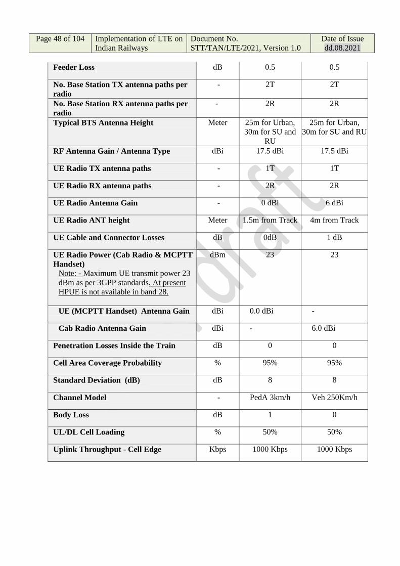
Page 48 of 104 Implementation of LTE on
Indian Railways
Document No.
STT/TAN/LTE/2021, Version 1.0
Date of Issue
dd.08.2021
Feeder Loss dB 0.5 0.5
No. Base Station TX antenna paths per
radio
- 2T 2T
No. Base Station RX antenna paths per
radio
- 2R 2R
Typical BTS Antenna Height Meter 25m for Urban,
30m for SU and
RU
25m for Urban,
30m for SU and RU
RF Antenna Gain / Antenna Type dBi 17.5 dBi 17.5 dBi
UE Radio TX antenna paths - 1T 1T
UE Radio RX antenna paths - 2R 2R
UE Radio Antenna Gain - 0 dBi 6 dBi
UE Radio ANT height Meter 1.5m from Track 4m from Track
UE Cable and Connector Losses dB 0dB 1 dB
UE Radio Power (Cab Radio & MCPTT
Handset)
Note: - Maximum UE transmit power 23
dBm as per 3GPP standards. At present
HPUE is not available in band 28.
dBm 23 23
UE (MCPTT Handset) Antenna Gain dBi 0.0 dBi -
Cab Radio Antenna Gain dBi - 6.0 dBi
Penetration Losses Inside the Train dB 0 0
Cell Area Coverage Probability % 95% 95%
Standard Deviation (dB) dB 8 8
Channel Model - PedA 3km/h Veh 250Km/h
Body Loss dB 1 0
UL/DL Cell Loading % 50% 50%
Uplink Throughput - Cell Edge Kbps 1000 Kbps 1000 Kbps

Page 49 of 104 Implementation of LTE on
Indian Railways
Document No.
STT/TAN/LTE/2021, Version 1.0
Date of Issue
dd.08.2021
10.6 Radio Network Planning:-
10.6.1 Radio network Planning needs to follow process of simulating the predicted
coverage and data rates from a given number of sites (eNB) based on certain
inputs like traffic, technology, product and required services through an
intelligent Simulation tool. The simulation tool runs its algorithm basis the
critical inputs provided, intended area, clutter spread, elevation variation,
Transmitted/Received power and propagations losses. The 3GPP/ITU Path
loss model or Okumara Hata model or any other model suitable for allotted
frequency of LTE for Indian Railways may be adopted for Path loss
calculation.
10.6.2 The Path Loss models may be Rural, Urban and Sub Urban selection of which
may be as per site requirement.
10.6.3 The coverage simulation may be carried out for design inputs with two or
more software from different OEM‟s in order to have cross verification and
better optimization. Actual cell range needs to be calculated using planning
tool where, clutter morphologies (like River, vegetation and other clutter
losses are considered.)
10.6.4 The coverage simulation software shall be proven and certified for its
application.
10.7 Cell Range and Inter eNodeB distance:
10.7.1
Urban Clutter
Urban Clutter - Veh250km/h -
20W Power Per Tx - 17.5 dBi
eNB Ant, 25m eNB Ant Height,
95% Coverage probability, 4m
UE HT
Urban Clutter - Ped3Km/h - 20W
Power Per Tx - 17.5 dBi eNB Ant,
25m eNB Ant Height, 95%
Coverage probability, 1.5m UE
HT
Cell Loading DL/UL % 50% 50%
UL Cell Edge
Throughput (Kbps) 1000 1000
Cell Range (m) 3.32 km 2.85 km
Design level (dBm) -97.5 -105.1
Sub Urban Clutter
Sub Urban Clutter - Veh250km/h
- 20W Power Per Tx - 17.5 dBi
eNB Ant, 30m eNB Ant Height,
95% Coverage probability, 4m
Sub Urban Clutter - Ped3Km/h -
20W Power Per Tx - 17.5 dBi eNB
Ant, 30m eNB Ant Height, 95%
Coverage probability, 1.5m UE
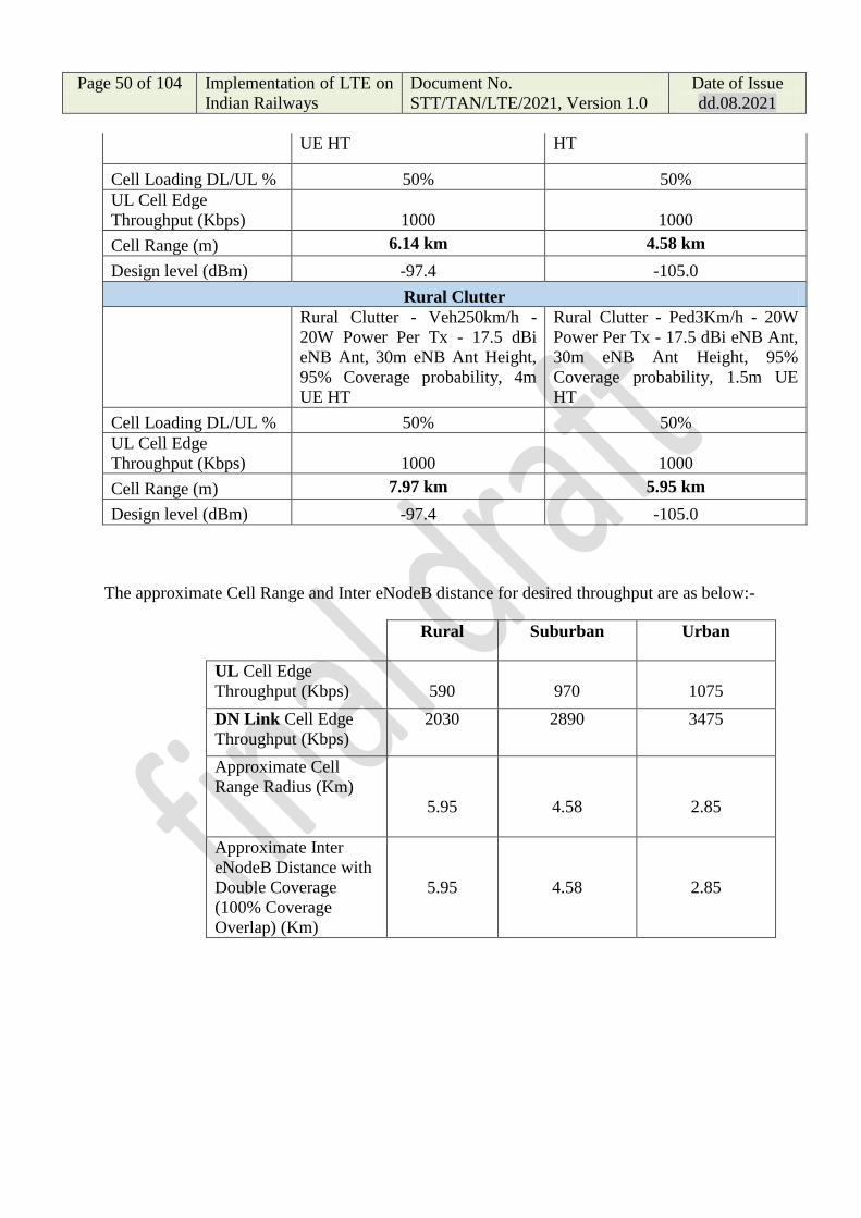
Page 50 of 104 Implementation of LTE on
Indian Railways
Document No.
STT/TAN/LTE/2021, Version 1.0
Date of Issue
dd.08.2021
UE HT HT
Cell Loading DL/UL % 50% 50%
UL Cell Edge
Throughput (Kbps) 1000 1000
Cell Range (m) 6.14 km 4.58 km
Design level (dBm) -97.4 -105.0
Rural Clutter
Rural Clutter - Veh250km/h -
20W Power Per Tx - 17.5 dBi
eNB Ant, 30m eNB Ant Height,
95% Coverage probability, 4m
UE HT
Rural Clutter - Ped3Km/h - 20W
Power Per Tx - 17.5 dBi eNB Ant,
30m eNB Ant Height, 95%
Coverage probability, 1.5m UE
HT
Cell Loading DL/UL % 50% 50%
UL Cell Edge
Throughput (Kbps) 1000 1000
Cell Range (m) 7.97 km 5.95 km
Design level (dBm) -97.4 -105.0
The approximate Cell Range and Inter eNodeB distance for desired throughput are as below:-
Rural Suburban Urban
UL Cell Edge
Throughput (Kbps)
590
970
1075
DN Link Cell Edge
Throughput (Kbps)
2030 2890 3475
Approximate Cell
Range Radius (Km)
5.95
4.58
2.85
Approximate Inter
eNodeB Distance with
Double Coverage
(100% Coverage
Overlap) (Km)
5.95
4.58
2.85

Page 51 of 104 Implementation of LTE on
Indian Railways
Document No.
STT/TAN/LTE/2021, Version 1.0
Date of Issue
dd.08.2021
10.7.2 The actual coverage shall be decided with Coverage Simulation software with
required design inputs and optimization through the Drive Test (optional) and
other measurements. But the minimum no. of eNodeB shall be provided as per
below:
Clutter Type Minimum No. of eNodeB Locations
per 100 route Km
Rural 15
Sub Urban 20
Urban 33
10.8 Dimensioning of Evolved Packet Core (EPC):
10.8.1 Evolved packet core has the following components that can be centralized and
shall be geo-redundant:
i) MME – Mobile Mobility Engine
ii) HSS – Home Subscriber Server
iii) PCRF – Policy Control and Routing Function
10.8.2 Following components of EPC shall be provided at each zone level in order to
reduce the packet delay to the RBC and vice versa:
i) Server Gateway
ii) Packet Gateway
10.8.3 EPC Core traffic profile:
EPC Traffic
Parameter
Unit Centralized Core
components Qty.
(Main Core Site)
Centralized Core
Components Qty.
(Geo-Redundant
site)
S-GW and P-
GW at each
zone
Total number
of subscribers Nos. 4,00,000 4,00,000 01 no
Total
Throughput Gbps 50 Gbps 50 Gbps
5 Gbps
10.8.4 EPC shall be support high availability and geo-redundancy with uptime of
99.999%.

Page 52 of 104 Implementation of LTE on
Indian Railways
Document No.
STT/TAN/LTE/2021, Version 1.0
Date of Issue
dd.08.2021
10.8.5 It should be expandable to cater higher capacities as per the Railways future
network requirements.
10.8.6 EPC shall be interoperable with any LTE-RAN vendor and vice versa.
10.9 Network ID Planning & Numbering Scheme:
10.9.1 Physical Cell Identity Planning:
The Physical Cell Identity (PCI) is the identifier of a Cell within the physical
layer of LTE network. The PCI consists of downlink Primary Synchronisation
Signal (PSS) and Secondary Synchronisation Signal (SSS). The PCI is used
for measurement reporting and handover.
10.9.1.1 The PSS consists of 3 different sequence numbers 0, 1 or 2 whereas SSS
consists of 168 sequence numbers ranging from 0 to 167. The Physical Cell
IDs range from 0 to 503 and are limited to 504 which can be reused. The PCI
is calculated as below:-
PCI = 3*SSS + PSS
10.9.1.2 Physical Cell Identity planning shall be done in such way that there should not
be same ID for neighbouring cells. Provision of spare IDs may also be done
for future use.
10.9.1.4 PCI Calculation: PCI calculation for example is given in the table below:-
Cell
Identity
No. of
Sectors
Sector
No.
SSS
(0 to 167)
PSS
(0, 1 & 2)
PCI =
3*SSS +
PSS
(0 to 503)
Reserved
SSS
A 1 1 0 0 0 1 & 2
- - - - - - -
D 2 1 5 0 15 6
2 1 16
- - - - - - -
G 3 1 19 0 57 20
2 1 58
3 2 59
- - - - - - -
XXX 4 1 167 0 501 1 & 2
2 1 502
3 2 503
4 0 0 0

Page 53 of 104 Implementation of LTE on
Indian Railways
Document No.
STT/TAN/LTE/2021, Version 1.0
Date of Issue
dd.08.2021
10.9.2 Numbering Scheme for Mobile Communication Network for Indian
Railways:-
10.9.2.1 The following numbers and identities are assigned for administration of each
mobile station in the network.
i) International Mobile Subscriber Identity (IMSI):
The structure of the IMSI will then be as shown in figure:
ii) Mobile Subscriber International Subscriber Directory Number (MS ISDN):
The structure of the MS ISDN will then be as shown in figure:
10.9.2.2 RDSO has approved and issued Uniform Numbering Scheme for Mobile
Communication Network (GSM-R) for Indian Railways. The same scheme
shall be applicable for LTE.
10.9.2.3 The IMSI and MSISDN for Indian Railway shall be as below:-

Page 54 of 104 Implementation of LTE on
Indian Railways
Document No.
STT/TAN/LTE/2021, Version 1.0
Date of Issue
dd.08.2021
Base Station Antenna & Tower of LTE for Indian Railways
:
10.10 Base Station Antenna & Tower of LTE for Indian Railways

Page 55 of 104 Implementation of LTE on
Indian Railways
Document No.
STT/TAN/LTE/2021, Version 1.0
Date of Issue
dd.08.2021
10.10.1 Base Station Antenna :
10.10.1.1 The Antenna shall work in 700 MHz spectrum (703-748 MHz Uplink & 758-
803 MHz Downlink, 3GPP/ETSI Band 28) with 5 MHz (paired) Carrier
bandwidth allocated to Indian Railways.
10.10.1.2 The Antennas to be used for Railway tracks shall be of directional type. Indian
Railways may have 1 Sector at Terminal stations and usually 2 Sectors for
single route sections in either direction of the Base Station (eNodeB). There
may be 3 or more Sectors in case for additional spur route in the junction
station/line.
10.10.1.3 LTE Antennas shall be installed with 2x2 MIMO techniques. The BBU and
RRH shall be hardware ready to support 2x2 MIMO and no. of Sectors as per
site requirement.
10.10.1.4 The technical parameters of Antenna shall be as per below or as specified by
the purchaser as per site requirement:-
S. No. Parameters Values
i) Antenna Type Directional
ii) Frequency Band Single Band (703-748 MHz Uplink &
758-803 MHz Downlink)
iii) No. of RF Connectors 02 nos. (IP 67 Rating)
iv) Antenna Gain 16 dBi to 21 dBi as per site requirement
v) Horizontal Half Power
Bandwidth (HPBW)
33º to 120º as per site requirement,
Note: High beamwidth antennas shall be
used for locations such as Station, Yards
or any other such location. Low
bemawidth antennas shall preferably be
used for the coverage of Railway Track.
vi) Remote Electrical Tilt (RET) Remote Electrical Tilt with manual
override (Manual Electrical Tilt)
vii) Physical Dimensions (LxBxH) As per OEM Specification
viii) Mechanical Specification Shall withstand wind velocity as per site
10.10.2 Tower Requirements :
10.10.2.1 The LTE Towers shall be ground based Towers, self-supporting type of
heights 25, 30, 35 and 40 meters or as per site requirement.

Page 56 of 104 Implementation of LTE on
Indian Railways
Document No.
STT/TAN/LTE/2021, Version 1.0
Date of Issue
dd.08.2021
10.10.2.2 The Towers shall preferably be of following types:-
i) 4 legged Angular Steel Tower
ii) 3 legged Tubular Steel Tower
iii) Hybrid of Angular and Tubular Steel Tower
iv) Monopole Steel Tower
10.10.2.3 Each Towers, Angular/ Tubular/ Monopole shall be designed specific to
site/location requirements. The Monopole Towers shall preferably be used
where there is a footprint restriction or any other reasons as per site condition.
10.10.2.4 The design parameter as per basic wind speeds based on 6 Zones of India shall
be as per below or as specified by the purchaser :-
Zones Basic Wind
Speed (Km/h)
Remarks
1 198 Tower Design Parameter : 200 Kmph
(198 Kmph ≤ Basic Wind Speed ≥ 180 Kmph) 2 180
3 169 Tower Design Parameter : 170 Kmph
(169 Kmph ≤ Basic Wind Speed ≥ 158 Kmph) 4 158
5 140 Tower Design Parameter : 140 Kmph
(140 Kmph ≤ Basic Wind Speed ≥ 119
Kmph) 6 119
10.10.2.5 The Tower shall be designed considering no. of Antennas & Equipment/
accessories, their physical dimensions and various other required factors. The
Tower design/drawing shall clearly mention no. of antennas & equipment and
their mounting locations on the Tower.
10.10.2.6 The Tower structure as per site requirement if any may have provision of
equipment platform at suitable height, Working/ Rest Platform, access ladders
and cable ladders etc. The fence and gate may be provided between tower legs.
10.10.2.7 The Tower design shall be approved by agencies such as Bureau of Indian
Standards (BIS), Telecom Engineering Centre (TEC), Structural Engineering
Research Centre (SERC), Central Power Research Institute (CPRI) and Indian
Railway/ RDSO or any other competent agencies/ institutions/ authorities as
specified by the purchaser.
10.10.2.8 The Tower Dimensions/ Design requirements shall be compliant to guidelines
issued by B&S Directorate, RDSO for „Design basis Report/ Checklist for
Design of superstructure of TCAS Tower‟ as per below or any other design
requirements issued by Railways/RDSO with latest version/ amendments:-

Page 57 of 104 Implementation of LTE on
Indian Railways
Document No.
STT/TAN/LTE/2021, Version 1.0
Date of Issue
dd.08.2021
S.
No.
Description Check points
1.0 General Arrangement Drawing of tower structure
a. Approved General
Arrangement Drawing
(GAD)
● Structural analysis and design of tower
structure to be done only after receiving
approved GAD of the tower for each location.
GAD should be approved by the competent
authority of the Zonal Railways.
● Approved GAD for each location is required
for knowing various parameters to be used in
analysis and design of structure. Some of
which are given below:
i. Tower Height
ii. Tower Type
iii. General arrangement of members in
structure
iv. Type of members to be used
v. Location details including its vicinity
vi. Wind Zone
vii. Effect of location on local wind
velocity and wind pressure
viii. Seismic Zone
ix. Corrosion proneness of location
x. Service life of structure
xi. Different type of antennae to be used in
tower and their details such as size,
dimensions, load etc.
xii. Locations of different antennae on
tower
xiii. Maximum limits of deflection, sway,
rotation of tower at different critical
points to be specified in line with
requirements of various equipment
being used on tower. If limits of
deflection, sway, rotation exceeds the
limits then these equipments might not
function and may render the tower
unusable
xiv. Any future requirement of equipments
during service life of structure
xv. Probable consequences of failure
xvi. Maintenance requirements

Page 58 of 104 Implementation of LTE on
Indian Railways
Document No.
STT/TAN/LTE/2021, Version 1.0
Date of Issue
dd.08.2021
xvii. Erection sequence/ construction
methodology of tower
xviii. Any other relevant information
which has effect on analysis and
design of structure as per site specific
condition.
2.0 Material Specification
a. Structural steel for
tower members
● Following codes may be used as per the type
of member used in tower construction:
i. Hollow circular steel tubes following the
provisions of IS 1161:2014.
ii. Hollow rectangular steel tubes following
provisions of IS 4923:2017.
iii. Rolled sections such as Steel Plates,
ISA, ISMC etc. to be as per standard
steel tables and steel should be as per IS
2062: 2011.
b. Properties of
structural steel for
members
● Clause 2.2 of IS 800:2007
c. Partial safety
factors for structural
steel
● As per clause 5.4.1 and Table 5 of IS
800:2007
d. HSFG bolting
assemblies with DTI
washers
● As per A&C 11 of IRS B1 or BS report no.
BS-111 (Revision 6)
● HSFG bolts of grade 8.8 to be used
preferably.
3.0 Loading and load combinations
a. Dead load ● Self-Weight of the Tower as per is 875 Part I
b. Superimposed Dead
and Live Loads
(SIDL)
● Antennae, Ladder, Platform (Rest &
Working), cables, Lightening arrestor,
Aviation signals etc. to be calculated as per
details given in approved GAD.
c. Live load ● As per details given in approved GAD or as
per IS 875 Part II.
d. Wind load calculation ● IS:875 Part-III (2015)
● Moreover in wind load calculation, the load

Page 59 of 104 Implementation of LTE on
Indian Railways
Document No.
STT/TAN/LTE/2021, Version 1.0
Date of Issue
dd.08.2021
calculation with different wind direction
with respect to structure should also be done
in order to find worst possible wind effect on
structure.
e. Seismic load
calculation
● IS:1893 Part- IV
f. Limit States of
strength and
serviceability
● Limit state of strength as described in Para
5.2.2.1 of IS 800:2007
● Limit state of serviceability as described in
Para 5.2.2.2 of IS 800:2007. Various limits
of deflection, sway, rotation of tower at
different critical points to be specified in
approved GAD.
g. Load combinations
for Limit State of
Strength and Limit
State of Serviceability
● Worst possible combinations of different
applicable loads as per clause 3.5.1, 5.3.3
and Table - 4 of IS 800:2007.
4.0 Structural Analysis
a. Software ● Software used for structural analysis should
be validated beforehand for its results and
for the purpose it is being used. Without the
validation of results for different types of
loads, loading combinations and support
boundary condition, a particular software
should not be used for structural analysis.
b. Method of
structural analysis
● As per relevant provisions mentioned in
section 4 of IS 800:2007.
5.0 Structural Design
a. Minimum
requirement of steel
sections from
durability
consideration
● It depends on type of members being
adopted in design i.e. Open sections or
hollow closed sections.
● Moreover, it will also depend on the type of
corrosive atmosphere to which the tower is
exposed, type of corrosion protection being
done, maintenance accessibility of tower and
expected service life of structure etc. These
parameters to be specifically mentioned in
the approved GAD.

Page 60 of 104 Implementation of LTE on
Indian Railways
Document No.
STT/TAN/LTE/2021, Version 1.0
Date of Issue
dd.08.2021
● In such cases apart from strength
consideration, the thickness/ section of
tower members is to be decided on the basis
of corrosion consideration. For different
corrosion category and corrosion protection,
expected service life or loss of thickness of
structural steel, guidance may be taken from
ISO 9223-2012 or ISO 12944.
● Moreover, in case of hollow steel sections,
special emphasis should be given on
connection details of members. Connection
details should be such that there should be no
ingress of water or moisture inside hollow
tubes to start corrosion internally in tubes
which cannot seen from outside.
b. Design of members
subjected to axial
tension in tower
● Tension capacity of tower members
subjected to axial tension should be
determined in accordance with relevant
provisions of Section 6 of IS 800:2007.
● Tension capacity should be more than
tension force in member due to worst
possible load combination.
c. Design of members
subjected to axial
compression in tower
● Compression capacity of tower members
subjected to axial compression should be
determined in accordance with relevant
provisions of Section 7 of IS 800:2007.
● Compression capacity should be more than
compression force in member due to worst
possible load combination.
● If member is subjected to tension as well as
compression forces in different
load combinations then both tension
and compression capacity should be
evaluated in accordance with relevant
provisions of section 6 and 7 of IS
800:2007 respectively. These should be
more than the applied compression and
tension forces in member.
d. Design of member
subject to bending in
● Moment capacity of tower members
subjected to bending should be determined

Page 61 of 104 Implementation of LTE on
Indian Railways
Document No.
STT/TAN/LTE/2021, Version 1.0
Date of Issue
dd.08.2021
tower in accordance with relevant provisions of
section 8 of IS 800:2007.
● Moment capacity of member should be more
than bending moment in member due to
worst possible load combination.
● If member is subjected to combined axial
force (i.e. Tension and/or compression) and
bending moment then relevant provisions of
clause 9.3 of IS 800:2007 should be used to
determine suitability of the member.
e. Bolted connection
design
● Bolted connection between members of the
tower or between member and its
attachment such as ladder, platform etc.;
should be designed in accordance with the
relevant provisions of section 10 of IS
800:2007 related to HSFG bolting.
f. Welding connection
design
● Welded connection design between members
of the tower should be designed in
accordance with the relevant provisions of
section 10 of IS 800:2007 related to welding.
g. Column bases for
connection of steel
members with
concrete column/
pedestals
● Column bases should be designed in
accordance with relevant provisions of
clause 7.4 of IS 800:2007
h. Displacement/deflect
ion, rotation, torsion
etc. for serviceability
condition at different
critical locations of
structure
● Displacement/deflection, rotation, torsion
etc. at serviceability condition to be
calculated as per load combinations load
combination mentioned in Table 4 of IS
800:2007.
● Calculated displacement/ deflection,
rotation, torsion etc. to be compared with
permissible limits given in the approved
GAD or in any other relevant document in
order to evaluate suitability of tower for
serviceability condition.
i. Construction stage
analysis and design
● Construction stage analysis based on the
erection sequence or construction
methodology given in approved GAD should
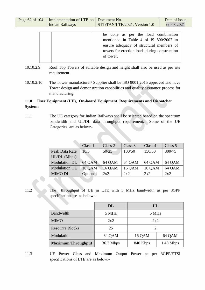
Page 62 of 104 Implementation of LTE on
Indian Railways
Document No.
STT/TAN/LTE/2021, Version 1.0
Date of Issue
dd.08.2021
be done as per the load combination
mentioned in Table 4 of IS 800:2007 to
ensure adequacy of structural members of
towers for erection loads during construction
of tower.
10.10.2.9 Roof Top Towers of suitable design and height shall also be used as per site
requirement.
10.10.2.10 The Tower manufacturer/ Supplier shall be ISO 9001:2015 approved and have
Tower design and demonstration capabilities and quality assurance process for
manufacturing.
11.0 User Equipment (UE), On-board Equipment Requirements and Dispatcher
System:
11.1 The UE category for Indian Railways shall be selected based on the spectrum
bandwidth and UL/DL data throughput requirement. Some of the UE
Categories are as below:-
Class 1 Class 2 Class 3 Class 4 Class 5
Peak Data Rate
UL/DL (Mbps)
10/5 50/25 100/50 150/50 300/75
Modulation DL 64 QAM 64 QAM 64 QAM 64 QAM 64 QAM
Modulation UL 16 QAM 16 QAM 16 QAM 16 QAM 64 QAM
MIMO DL Optional 2x2 2x2 2x2 2x2
11.2 The throughput of UE in LTE with 5 MHz bandwidth as per 3GPP
specification are as below:-
DL UL
Bandwidth 5 MHz 5 MHz
MIMO 2x2 2x2
Resource Blocks 25 2
Modulation 64 QAM 16 QAM 64 QAM
Maximum Throughput 36.7 Mbps 840 Kbps 1.48 Mbps
11.3 UE Power Class and Maximum Output Power as per 3GPP/ETSI
specifications of LTE are as below:-

Page 63 of 104 Implementation of LTE on
Indian Railways
Document No.
STT/TAN/LTE/2021, Version 1.0
Date of Issue
dd.08.2021
UE Power Class &
Maximum Output Power
EUTRA Bands Class 1 Class 2 Class 3
All Bands (1 to 70)
(including Band 28 - FDD,
UL 703 MHz – 748 MHz &
DL 758 MHz – 803 MHz)
x x 23 dBm
(200 mW)
Band 14 31 dBm
(1.25 mW)
x x
Band 41 x 26 dBm
(400 mW)
x
Band 47 x 26 dBm
(400 mW)
x
11.4 Cab Radio System :
11.4.1 Each Train Engine (Loco) shall be provided with 2 nos. of Cab Radio Systems
in redundant mode for Indian Railways front and Rear Loco compartments.
The Cab Radio System shall provide Voice and Data communication for train
operational requirements.
11.4.2 The Cab Radio System shall support 3GPP/ETSI LTE spectrums and
bandwidths. It shall work on the spectrum assigned for LTE to Indian
Railways. Cab Radio System shall support Mission Critical application as per
3GPP/ETSI release 16 or later specifications.
11.4.3 The Cab Radio System shall meet TCAS/ETCS standard requirements as per
relevant specifications for train operation and automation system for Indian
Railways.
11.4.4 The Cab Radio System shall meet requirements of FRMCS specification. The
Cab Radio shall have the following minimum functions/features:-
a) Driver call related functions:
i) Call controller.
ii) Call other drivers in the area.
iii) Send railway emergency call.
iv) Confirm receipt of railway emergency calls.
v) Communicate with other drivers on the same train.
vi) Call train staff.
vii) Call other authorized users.
viii) Receive incoming voice calls.

Page 64 of 104 Implementation of LTE on
Indian Railways
Document No.
STT/TAN/LTE/2021, Version 1.0
Date of Issue
dd.08.2021
ix) Terminate calls.
x) Receive text messages.
xi) Enter/leave shunting mode.
xii) Monitor calls to other on train users/devices.
xiii) Forward calls/cancel call forwarding to/from driver hand held.
b) Other driver related functions:
i) Powering up radio.
ii) Switch radio MMI on and off.
iii) Select language.
iv) Adjust loud speaker volume.
v) Select mobile radio network.
vi) Register and deregister train number.
vii) Register and deregister on train users.
viii) Register and deregister stock numbers.
ix) Store/retrieve numbers and their details.
x) Invoke supplementary services.
xi) Invoke tests.
c) Other cab radio functions:
i) Automatic connection of incoming calls to appropriate on-train users or
devices (conductor, public address system, data systems, etc).
ii) Automatic establishment of outgoing calls initiated by on-train users or
devices.
iii) Automatic handling of calls of varying priorities.
iv) Send to the controller(s) a signal on activation of driver safety device.
v) Transmit Railway emergency call event indication to „train-borne
recorder‟.
vi) Run-time diagnostics
11.4.5 The Cab Radio System may include the following sub systems:-
i) LTE Router/ Modem (Central Control Unit)
ii) Control Panel (MMI) & Display Unit
iii) Microphone & Speaker and MC PTT Handset and Cradle
iv) Rail Rooftop Low Profile Antenna
v) Dual Redundant Power Supply

Page 65 of 104 Implementation of LTE on
Indian Railways
Document No.
STT/TAN/LTE/2021, Version 1.0
Date of Issue
dd.08.2021
11.4.6 One Cab Radio System shall consist of at least two Mobile network
terminations, in active/ standby configuration i.e. comprising of minimum two
mobile equipments and SIM cards.
11.4.7 The SIM cards shall be physically integrated with the cab radio set and shall
not be able to be removed except by maintenance staff.
11.4.8 The Control Panel shall consist of capacitive touch screen display unit of day
light readable type for displaying information. Control panel shall have
dedicated hard buttons configurable for specific functions.
11.4.9 Cab Radio System shall receive remote software upgrades via a ground-based
management terminal. Cab Radio System shall also support software updates
via USB Stick. There shall be provision for retrieving system logs from
USB/Ethernet ports.
11.4.10 The Speakers in the Driver Cab shall be loud enough to be audible in the
running Train. The radio should be able to provide five levels of adjustment
(numbered 1 to 5) for each volume range setting. The following table details
the levels of adjustment and the three (Quiet, Normal and Noisy cab)
loudspeaker ranges to be provided.
Levels of
adjustment
Driver adjustment
Quiet cab Normal cab Noisy cab
250 mW 24 dBm 1 1
355 mW 25.5 dBm 2
500 mW 27 dBm 3 (Default) 2 1
1 W 30 dBm 4 3 (Default) 2
2 W 33 dBm 5 4 3 (Default)
4 W 36 dBm 5 4
8.5 W 39 dBm 5
11.4.11 Separate Rail Rooftop Low Profile Antenna shall be provided for each Cab
Radio System.
11.4.12 The Cab Radio System shall be connected to TCAS/ ETCS systems with
suitable interfaces through LTE Router/ Modem equipment. The Cab Radio
System shall also be connected to other on-train systems application through
LTE Router/ Modem equipment. The following interfaces for the on-train
systems application may be provided:-
i) TCAS/ETCS
ii) Train borne recorder

Page 66 of 104 Implementation of LTE on
Indian Railways
Document No.
STT/TAN/LTE/2021, Version 1.0
Date of Issue
dd.08.2021
iii) Public Address interface
iv) Intercom and other interfaces as required
Note : The various equipment in the Cab and their redundant equipment shall
be connected over Optical Fibre Media or any other media of industry
standard in Ring Arrangement.
11.4.12.1 The various systems/sub systems in the Cab Radio System for voice and data
shall be connected with suitable cables and wires complying to relevant
specifications and standards for Rolling Stock Application.
11.4.12.2 The Ethernet interface between Cab Radio and client application shall be on
industrial grade fibre or CAT6 cable with suitable M12/M23 connectors.
11.4.13 An emergency power supply should be provided for Cab Radio System which
will enable the driver‟s radio to continue to operate for a period of at least 2
hour in the event of failure of the train‟s main power supply.
11.4.14 All design, manufacturing, testing and installation of Cab Radio equipment
shall comply with the quality procedures defined in ISO 9001.
11.4.15 The Cab Radio System shall have the following minimum specifications or as
specified by the purchaser:-
S. No. Parameter Values
i. Long Term Evolution (LTE)
and GSM Standards
● Latest 3GPP/ETSI 4G specification,
upgradable to 5G specification
● Support 3GPP/ETSI 4G and 5G
spectrums and FDD bands for Indian
Railways
● Support GSM 900 MHz
ii. Maximum Transmit Power 23 dBm (+2/-2.5), EUTRA Band 28, Class 3
Note: - Maximum UE transmit power 23
dBm as per 3GPP standards.
iii. Antenna Gain (with external
Rail Rooftop Low Profile
Antenna)
6 dBi (minimum)
iv. UE Category Category 2 or higher based on spectrum
bandwidth and DL/UL throughput

Page 67 of 104 Implementation of LTE on
Indian Railways
Document No.
STT/TAN/LTE/2021, Version 1.0
Date of Issue
dd.08.2021
v. Mobile Network Termination
(mobile equipment)
Minimum 02 Nos.
vi. SIM Card Slots ● Nano SIM
● Dual SIM (LTE+GSM, LTE+LTE)
● Embedded SIM (e-SIM) may be used
instead of commercial SIMs for better
reliability and ease of use
● VoLTE Ready (Optional, as per
requirement)
vii. Positioning and Timing
Services
Indian Regional Navigation Satellite System
(IRNSS) or Global Positioning System
(GPS)/US any other services applicable to
Indian Railways
viii. Wi-Fi ● 2.4 GHz and 5 GHz
● Standards 802.11 a/b/g/n/ac
ix. Control Panel Display
● 10.0 ” or higher
● 800x400 or higher resolution
● Capacitive touch-screen
● Sunlight Readable
x. Interfaces/ Ports ● GSM/4G/5G Antenna
● IRNSS/GPS
● Ethernet/MVB
● Microphone, Speaker, MCPTT Handset
● Power Supply
● USB, RS-232/RS 485
● Digital I/O
xi. Operating System Software Android/ Linux
xii. Environmental Requirements
Operating Temperature ● -20°C to +70°C
● The aerial and any other equipment
mounted external to the train shall be
capable of withstanding extremes of
temperature from -40°C to +70°C
● The aerial and any other equipment
mounted external to the train shall
function during rapid temperature
fluctuations of up to 3°C/second
Humidity 95% (non condensing)

Page 68 of 104 Implementation of LTE on
Indian Railways
Document No.
STT/TAN/LTE/2021, Version 1.0
Date of Issue
dd.08.2021
Altitude -100m to 1800m above Sea level
Pressure Equipment mounted external to the train cab
shall withstand the following physical
conditions:
● in-tunnel pressure pulses of 6 kPa (peak
to peak) for up to 3 seconds;
● pressure gradients of up to 100 kPa/s.
Temperature, Humidity and
Vibration
EN50155/IEC60571 for Rolling Stock
application
Protection against
Flammability
Cab-Radio including items such as cables
used in its installation on a train shall be
protected against flammability in compliance
with the relevant provisions of EN 45545
parts 1 and 2.
Electromagnetic
Compatibility (EMC) : Both
Emission and Immunity
Electromagnetic interference immunity and
emissions from the Cab Radio and its
associated antenna system (connecting cable
and antenna) shall comply with the
requirements defined in EN 50121 parts 1 and
3-2.
Protection against Electrical
Hazards
The driver and other in-cab equipment shall
be protected against all electrical hazards
arising from Cab Radio equipments as per
EN 50153
Voltage fluctuations and
Transients
The Cab radio main and backup power
supplies shall comply with the voltage
fluctuations and transients as defined in EN
50155
Ingress Protection (Dust
Resistance & Water
Immersion)
IP65 compliance according to EN 50155/IEC
60571
Note: BIS standards equivalent to EN/IEC Standards shall also be applicable
11.5 Rail Rooftop Low profile Antenna:

Page 69 of 104 Implementation of LTE on
Indian Railways
Document No.
STT/TAN/LTE/2021, Version 1.0
Date of Issue
dd.08.2021
11.5.1 LTE Cab Radio Rail Rooftop Low profile Antenna shall cover LTE
spectrums and bandwidths. It shall work on the spectrum assigned for LTE to
Indian Railways.
11.5.2 The mechanical dimension shall be such that it meets mounting requirements
on the Rail Rooftop of Indian Railways for electrified and non electrified
sections, Sub urban sections, bridges, tunnels etc.
11.5.3 The antenna shall be Omni directional with minimum 6 dBi gain and support
minimum 2 x 2 MIMO antenna configuration.
11.5.4 Embedded antenna for Positioning and Timing Services (IRNSS/GPS) with
integrated LNA and protected by integrated surge arrestors.
11.5.5 Compliant with Railway standards as per EN 50155 or equivalent BIS/IEC or
other specifications.
11.5.5 Compliant with Fire retardant as per EN 45545-2 or equivalent BIS/IEC or
other specifications.
11.5.6 High voltage (25 KV) and high current (40kA/100 ms) protection
11.5.7 Suitable for train speeds for 220 Kmph or higher as per requirement
11.5.8 Antenna shall have Safety and EMI/EMC requirements as per
Railway/industry standards and regulations.
11.5.9 Operation temperature: -40 to +70 degree Celsius or higher.
11.5.10 Ingress Protection (IP) rating should be IP67 or better.
11.6 MCPTT Handset Specification:
11.6.1 The MCPTT Handsets shall support latest 3GPP/ETSI LTE spectrums and
frequency bands. It shall work on the spectrum assigned for LTE to Indian
Railways.
11.6.2 MCPTT Handsets shall also support the GSM-900 MHz network of Indian
Railways.
11.6.3 It shall support Mission Critical application as per latest 3GPP/ETSI release 16
or later specifications and support Carrier Aggregation (CA). 11.6.4
The environmental and physical specification of the MCPTT Handset shall be
as close as possible to that of a Commercial-Off-The-Shelf (COTS) mobile
whilst adhering to the specifications provided.
11.6.5 The MC PTT handset shall have following minimum specifications:-
S. No. Parameter Values

Page 70 of 104 Implementation of LTE on
Indian Railways
Document No.
STT/TAN/LTE/2021, Version 1.0
Date of Issue
dd.08.2021
i. Long Term Evolution (LTE)
and GSM Standards
● Latest 3GPP/ETSI release 16 or
later specification, Support FDD
and frequency bands for Indian
Railways
● Support GSM 900 MHz
ii. Maximum Transmit Power 23 dBm (+2/-2.5), EUTRA Band 28,
Class 3
iii. Antenna Gain (single integral
antenna)
0 dBi
iv. UE Category Category 2 or higher based on spectrum
bandwidth and DL/UL throughput
v. Chipset ● Octa Core Processor
● Qualcomm Snapdragon 630
Processor or Exynos9810 or similar
processor
vi. Memory
● 4 GB RAM
● 64 GB Internal Storage
● Storage expandable up to 128 GB or
higher with external microSD Card
● 128 GB microSD card
vii. SIM Card Slots ● Nano SIM
● Dual SIM (LTE+GSM, LTE+LTE)
● Embedded SIM (e-SIM) may be
used instead of commercial SIMs for
better reliability and ease of use
● VoLTE Ready (Optional, as per
requirement)
viii. Positioning and Timing
Services
Indian Regional Navigation Satellite
System (IRNSS) or Global Positioning
System (GPS)/US any other services
applicable to Indian Railways
ix. Wi-Fi ● 2.4 GHz and 5 GHz
● Standards 802.11 a/b/g/n/ac
x. Bluetooth Bluetooth 5.0 or higher
xi. Near Field Communication
(NFC)
Support
xii. Display ● 5.0” or larger
● HD (1280 x 720p) or Higher

Page 71 of 104 Implementation of LTE on
Indian Railways
Document No.
STT/TAN/LTE/2021, Version 1.0
Date of Issue
dd.08.2021
● Capacitive, touch-screen with
Gorilla Glass
● Glove and wet usable capacitive
touch screen
● Sunlight Readable
xiii. Camera
● Rear 12 Mega Pixel or higher, Auto
Focus, LED Flash, Digital Zoom
● Front 8 Mega Pixel
xiv. Sensor Platform
● Fingerprint Sensor
● Proximity Sensor with Gesture
Sensor
● Ambient Light Sensor
● Accelerometer
● Barometer
● Gyroscope
● E-Compass
xv. Interfaces/ Ports USB-C, 3.5mm audio (stereo)
xvi. Mission Critical Buttons
● Dedicated PTT Button
● Dedicated Emergency Button
● Talkgroup Selection Switch
● 2 Programmable Buttons
● Power Button
● Volume (Up / Down) Buttons
xvii. Battery ● Li-Ion Battery/ Li-Polymer Battery
● 4500 mAh or higher as specified by
purchaser
● Embedded or Removable/Field
Swappable
xviii. Software
Operating System Android 9/ Android Oreo similar or
higher version
Google Mobility Services Enabled (Pre-installed)
xix. Audio
Input
Multi microphones active noise
suppression and echo cancellation
Output 109 dB SPL at 5cm

Page 72 of 104 Implementation of LTE on
Indian Railways
Document No.
STT/TAN/LTE/2021, Version 1.0
Date of Issue
dd.08.2021
Audio Formats
Support formats such as PCM, MP3,
AAC/AAC+/eAAC+, WMA, WMA
Lossless, WMAPro 10, AMR NB/WB,
FLAC, ALAC, Vorbis, APE, AC3,
eAC3, Non Native DSD or any other as
per system requirements
xx. Video and Imaging
Video
● Support H.263, H.264, H.265,
MPEG-4, VP8/VP9 or any other as
per system requirements.
● Supported for Playback, Streaming
and Recording
Image Support JPEG, GIF, PNG, BMP, WBPM,
WebP or any other as per system
requirements
Supported File Types 3GPP, MPEG-4, WebM or any other as
per system requirements
Video Recording Quality ● 4K UHD @ 25 fps, H.264/H.265
● FHD (1080p) @ 25 fps,
H.264/H.265
● Provision for other HD and SD
resolutions
xxi. Security Root Detection, Multi-Factor
Authentication, Remote Configuration,
OTA Firmware and Software Upgrades,
Application Whitelisting, Over-the-Air
Wipe and Lock, Real-Time Integrity
Monitoring, Malware Blocking Resource
Management or similar
xxii. Environmental Requirements:
Operating Temperature -20°C to +55°C
Humidity 95% (non condensing)
Altitude -100m to 1800m above Sea level
Temperature Shock,
Mechanical Shock, Drop, Salt
Fog, Solar Radiation,
MIL STD 810G or equivalent

Page 73 of 104 Implementation of LTE on
Indian Railways
Document No.
STT/TAN/LTE/2021, Version 1.0
Date of Issue
dd.08.2021
Vibration. Shock, Humidity
Dust Resistance & Water
Immersion
IP67 (IEC 60529) compliance with
installed battery or higher
Electrostatic Discharge IEC 61000-4-2, Level 4 or equivalent
xxiii. Device Safety IEC/UL/EN 60950 or equivalent
xxiv. Electromagnetic
Compatibility & Immunity
EN 61000 part 4-3 or equivalent
xxv. Accessories ● Stereo headset
● Charger
● USB-C cable
● SIM tray tool
Note: BIS standards equivalent to MIL/EN/IEC/UL Standards shall also be
applicable
Page 74 of 104 Implementation of LTE on
Indian Railways
Document No.
STT/TAN/LTE/2021, Version 1.0
Date of Issue
dd.08.2021
11.7 Dispatcher System:
The Dispatching System should be able to provide a flexible, reliable and comfortable
solution enabling efficient and effective voice and text-message communication and
communication management in various PMR communication technologies such as LTE and
PBX network environment. It should be used in, e.g.:
- dispatching centers for the controlling and handling of entire fleets of subscribers,
- centers of effective alarm and control functions,
- emergency center for handling specific, public and other emergent events,
- other management and operational centers.
Dispatching System shall use IP based interface to connect to the communication network
infrastructures for voice communications. It should support IP-based architecture and packet-
switch-based message routing strategy.
Dispatcher System should run on commercial off-the-shelf (COTS) hardware.
Dispatcher System should be built on a client / server architecture.
Dispatcher should be developed on top of a multi-technology and multi-vendor platform.
11.7.1 Introduction
Multi network connectivity
- The Dispatching system should support full IP architecture & capable to interconnect
to several different communication technologies such as LTE, PSTN, PBX and
several others. It should provide the interconnection between such networks and also
the capability of conferencing across these networks.
Reliability
- The central server system should be provided in a full redundant configuration which
can even run on virtualized environments to meet the state of the art reliability and
data center requirements.
Graphical user interface
- Dispatching System should support Graphical User Interface, shall be designed both
for a touch screen and conventional operation.
Inter-operability with other subsystems
- The Multi Network Dispatching system interworks seamlessly with other subsystems
such as Multi Network Tracking System. This enables unique features such as “touch
and call” i.e. select a target such as a train on the track and initiate a call procedure to
the target.

Page 75 of 104 Implementation of LTE on
Indian Railways
Document No.
STT/TAN/LTE/2021, Version 1.0
Date of Issue
dd.08.2021
11.7.1.1 Interfaces
The system supports following interfaces off-the shelf:
- Generic: IP, PSTN, PBX: SIP – RFC 3261
- LTE overlay via dedicated MCX Server
- Location data: support of Intelligent Network and other location data source
integration
- Support of location-based services in LTE networks. The data source could be the
client SW or other sources
11.7.1.2 Administration
Each Dispatching System system should facilitate a variety of hierarchical roles to facilitate
administration. The administration procedure shall include:
- Definition of dispatcher users
- Definition of role(s) and its rights
- Definition of role visibility set
- Definition of phonebooks
Each dispatcher user should be identified by its user name/login and password necessary to
access the application. The user should be assigned to single or multiple roles at a time; the
use can dynamically control the list of active roles.
The roles should be defined either as personal or parallel roles. In the 1st case, the role should
be assigned exclusively to a particular user. In case of parallel roles, multiple users should be
able to login to the role at the same time having the same authorizations and sharing the
resources –like phonebooks.
Each role should be associated with a visibility set represented by a list of radios which
should be monitored and controlled by the operator(s). The definition of the visibility set
should be done manually in the dispatching system administration. The visibility set should
be defined as range or multiple ranges of addresses. System should support flexible
configurations reflecting the customer operational scenarios:
- A range can be assigned exclusive to single role or
- the same range(s) can be assigned to multiple roles
- ranges assigned to different roles can overlap
The radio represented by its individual address and Alias is either created manually in the
administration tool or can be imported from the PMR infrastructure (infrastructure dependent
capability).
The administration should be flexible enough to allow separation of various customers and
even multiple user organizations of the same customer sharing the same dispatching server.

Page 76 of 104 Implementation of LTE on
Indian Railways
Document No.
STT/TAN/LTE/2021, Version 1.0
Date of Issue
dd.08.2021
11.7.1.3 User Interface
The Dispatching System client GUI should be able to enable quick and easy access to all
communication resources independent of the communication technology and type of device.
The graphical user interface should be supported as detailed below:
1 Administration area Provides access to role or network and basic user controlled
administration such as password definition or language selection
2 Phonebook area Provides access to network specific list of addresses according
visibility settings.
Provides fast filtering options based on system wide and also
operator defined tags
3 Action switch Main action toolbar setting active action such as “call” or
“messaging” or “browsing”
4 Incoming call queue Common network independent call queue
5 Hold queue Operator specific calls on hold queue
6 Active call area Common panel used for outgoing and connected incoming call
widget presentation with dedicated per call controls
7 Call control
functions
Set of control actions used to modify the call parameters such as
put to conference, mute, push to talk control, …
8 Status and
information area
Set of indications providing supporting information for the
operator such as operator call forwarding settings, indication for
missed calls, new messages, call back requests…
9 Messaging panel Dedicated panel used for data messaging
10 Alarm panel Presentation and handling of man down and call back requests
events
11 Event list panel Rolling time log containing operator‟s action and various events
with fast call back or message back action buttons
11.7.2 Features of Dispatching System
11.7.2.1 Role Management
Each of the connected networks shall be represented by a dedicated role (or even multiple
roles) with specific visibility set of addresses (phonebook) accessible via a horizontal tab
controller.
Selection of a particular tab (tab LTE, tab Telephony etc) shall lead to presentation of all
identities/addresses belonging to the particular subsystem filtered according to the assigned
visibility set to the particular role of the Dispatcher System.
All identities from all subsystems shall be the subject of visibility control. Various operators
may have different authorization levels to work with specific users in the field. There should
be a supervisor level operator having access to all users from all subsystems, in parallel with
Page 77 of 104 Implementation of LTE on
Indian Railways
Document No.
STT/TAN/LTE/2021, Version 1.0
Date of Issue
dd.08.2021
other operator logins having access to only a part of the users. This authorization level shall
be assigned to a particular operator login, not to a physical dispatcher client itself.
Each role shall be identified by its name and set of parameters and shall be assigned to a set
of users who are allowed to login to the role. A user may login to multiple roles at the same
time, even in different modes reflecting the operational scenario and authorization settings
defined in the Dispatcher System system administration tool.
Dispatcher System shall offer flexible role management system, enabling administrable
assignment of multiple roles to the controller. The assignment type can be personal or
parallel.
In parallel role, multiple controllers (users) should be able act in shared mode in the certain
dispatcher role; as example incoming call presented and ringing in the incoming call queue of
all clients logged in to the parallel role; activity of one operator is visible to all other
operators logged into the parallel role etc. Personal role is special controller role assigned to
the person.
As described, the Dispatcher System role management allows flexible sharing of events in a
common role. In addition, in case of operational needs, the role can be taken over by
exclusive right assigned to a particular user.
Additional parameters may be configured for each role supporting the operational procedures
of the end users such as:
- Indication of number of logged in users in a role
- Minimum number of users supporting 24h operational scenarios if applicable (in case
a user tries to log out and the rule should be violated, logout shall be refused and the
user shall be prompted to “swap” shift with another user before he terminates the
session)
11.7.2.2 Location data handling
The solution shall support location-based services. Depending on the connected technology,
the intelligence shall be based on infrastructure services providing direct location data from
various sources such as balises at rails or GPS information from the cab radios.
In both cases, the data is provided in proprietary formats which can be integrated into the
Dispatcher System solution. The solution supports definition of relations between the
location data and the control area of the individual dispatching system roles allowing
operational calls and events distribution. Dynamic train and mobile stations lists based on the
available location data should be created and presented in the control areas of the individual
dispatcher roles.

Page 78 of 104 Implementation of LTE on
Indian Railways
Document No.
STT/TAN/LTE/2021, Version 1.0
Date of Issue
dd.08.2021
11.7.2.3 Workspace handling
The administration system shall allow assignment of visibility sets (represented by
phonebooks) to each of the roles. The phonebooks should be accessible in a dedicated area,
again, in a network independent common style simplifying the operators‟ actions and usage
complexity.
There are four generic workspaces represented on the application user interface:
Phonebook The destination tab shows all the elements in the network
that are visible to the current user / role.
Favorites The dispatcher can place units (using drag/drop) on the
favorite panel, so the dispatcher can organize the database
according to the everyday usage.
Search Dispatcher can filter the destinations by the alias or dial
number
Browser Detailed information about one unit and unit-specific
feature(s) are shown in this panel
Each of the phonebook entry shall provide information about the represented address.
In case of network wide relevant status of a particular identity (e.g. user in the field/number
in call or idle or in disabled state), the central database approach should naturally support
effective information distribution to all of the authorized clients (compared to inter thick-
client communication sharing/broadcasting the same status information among each other).
The phonebook area shall support filtering of entries based on pre-defined and user defined
triggers as well ensuring effective overview creation in case of challenging situations. As
example:
- Show list of individual numbers
- Show list of static or dynamic group numbers
- Show list of controllers
- Show list users tagged by tag_1 up to tag_4 (represented by filter)
In addition to phonebook selection area, the operator should have a capability to define and
organize a set of favorites for each network/role in multiple tabs. The favorites should be
freely selectable from the whole visibility set, may be assigned a specific position in a grid
shall be the subject of user specific profile data. The definition of the favorites shall be done
either by drag and drop action or left-right definition panel.
The operator should be able to define favorites relevant for himself and for all users logged in
the same role – so called user specific favorites and role specific favorites.

Page 79 of 104 Implementation of LTE on
Indian Railways
Document No.
STT/TAN/LTE/2021, Version 1.0
Date of Issue
dd.08.2021
11.7.2.4 Action handling
The Dispatcher System operation shall be based on simple principle – Select action, select
destination”. The action selection shall be done on the action toolbar and includes as
minimum:
- Call: call setup
- Messaging: short data messaging
- Group attachment control: allowing operator specific control of incoming direct calls
presentation
- Browsing: generic browsing mode providing details upon selected addresses or even
calls
Call action selection shall lead to outgoing call setup to the selected phonebook entry.
Similarly, in case of Messaging action selection, the radio chosen in the phonebook or
favorites should be added to the message destination list.
Group attachment shall be used to control the incoming group calls to the particular operator
workstation. Browsing shall provide additional data about the selected entry from the
phonebook/favorites list or even about an ongoing call or conference.
Example of network specific action and its handling – group attachment control:
- In case of group attachment control activation, all addresses for which the action is
not applicable should be grayed out in the phonebook area, only valid addresses
where group attachment can technically be applied, shall be selected by the operator
- In case of group number selection, the state shall either set to “attached/de-attached”
(toggle function)
- In case of attached group (“equals to” unmute group audio): the audio of the incoming
call on the particular group shall be connected to the operator and active call widget
should be created in the connected call area
- In case of de-attached group (“equals to” mute group audio): the incoming call on the
particular group shall not be connected to the operator
� The operator shall have multiple groups defined in the visibility set, he/she should
be able to actively control which groups are operationally relevant for a particular
situation and perform group attachment/de-attachment action allowing parallel
voice stream activation from multiple group calls
� Note: there should be a system defined parameter controlled in the administration
tool – always scanned group – which shall ensure that a group cannot be de-
attached by a operator, not even by mistake – valid e.g. for emergency groups
In addition to call and data messaging actions, the Dispatcher system shall support a
browsing mode in which detailed information related to a particular address, call or a
conference are rendered on the user interface.
The detailed view shall provide a condensed summary of details such as:

Page 80 of 104 Implementation of LTE on
Indian Railways
Document No.
STT/TAN/LTE/2021, Version 1.0
Date of Issue
dd.08.2021
- Call/Conference participants with details
- Call/Conference state
- Call priority
- Time stamp and duration
- Relevant action buttons such as terminate call/conference, remove from conference
11.7.2.5 Call handling
The VD client shall provide a common incoming call queue (ICQ). ICQ shall be used for
presentation of all incoming calls with hook signaling. All outgoing (and also
connected/ringing outgoing calls) shall be presented in a dedicated call panel.
Both ICQ and call panel shall be common for all the roles logged in on the particular
workstation.
Each of the incoming calls shall be represented by a dedicated widget listed according to the
time stamp as they arrive to the queue and by the priority as well (highest priority on top).
The operator may simply accept or deny the call by clicking on the widget. In case of parallel
roles, the incoming call shall be presented to all users logged in to the particular role, after the
first operator accepts the call; widget should be removed from the ICQ of other operators.
Incoming call queue shall support auto-answering procedures. Based on the timers defined in
the administration tool, different priority calls shall be auto-answered after timer expiration.
Example: incoming emergency call
- Incoming call widget presented in the ICQ
- Dedicated audio indication
- Dedicated visual indication (red background)
- Operator either accepts the call manually or after 10s timer expiration, the call is auto-
answered (in case there is a timer set for auto-answering in the administration tool for
the specific call priority)
- In case of ongoing call, the focus of the call is automatically transferred to the auto-
answered emergency call (except the operator is already handling another emergency
call)
Accepted incoming calls and outgoing calls initiated by the operator shall be displayed in a
common active call panel. It means that all calls, regardless of underlying network, shall be
represented by a call widget rendered in the active call panel.
The call widget shall contain the information about:
- Call source and destination - represented by alias and number
- Direction of call - represented by icon: outgoing

Page 81 of 104 Implementation of LTE on
Indian Railways
Document No.
STT/TAN/LTE/2021, Version 1.0
Date of Issue
dd.08.2021
- Priority of the call - represented by color code: green (note: numeric value visible in
browser)
- In case of incoming calls – call priority and type dependent ringing call
- Action buttons:
Call details (browser)
Volume control
Call transfer
Audio Routing between speakers
Call hold
Call hang-up
The VD solution shall support multiple connected call handling within one VD client. In case
of multiple calls, there should be one microphone focus assigned to a selected call widget. It
means that the microphone should be transferred to one call in a time; besides the uplink
audio route from the other calls is mixed to the selected output device. The operator shall
actively control the microphone focus assignment between the multiple calls.
11.7.2.6 Call control functions
VD client application shall provide a dedicated panel for call control functions.
PTT button to request and return speech right
Merge into conference
Manual dial pad
Mute microphone
Mute speaker
Mute headset
Public emergency call (PEC)
Radio emergency call (REC)
As described above, the VD system shall provide role specific (example: phonebook) and
common panels (incoming call queue, connected calls). In case of multiple connected active
calls should be presented in the active call panel; also, the operator should be able to initiate a
conference call. The operator should be able to simply merge the calls into a common
conference without network limitations. In case of conference details or further control, the

Page 82 of 104 Implementation of LTE on
Indian Railways
Document No.
STT/TAN/LTE/2021, Version 1.0
Date of Issue
dd.08.2021
operator should be able to switch to the browser with further action capability such as
terminate or remove particular user.
In order to support semi duplex communication, the VD system shall provide multiple push-
to-talk buttons (PTT):
- Software PTT on the user interface
- Hardware PTT integrated in the handset/footswitch or desktop microphone
Speech item requests and grants should visually be (background color indication on the
software PTT) indicated with gentle audio indication as well. As described above, the
operator shall be able to focus a particular call and in case of semi duplex communication,
he/she can press the PTT button (either soft or hard PTT) in order to transfer his voice to the
other call participants. The operator may even pre-empt a speech item of field user.
In addition to call setup via action and destination selection in the phonebook or favorite tab,
the operator should be able to setup a call via a manual dial pad panel as well by simply
entering the destination number and clicking on the call button.
The VD solution shall support workstation relevant and call relevant audio handling. The
generic call control buttons shall control the microphone and speaker audio stream – on/off -
mute/unmute of the whole workstation. In addition to that, the operator shall be able to
control the audio routing and audio setting per each call. In case of multiple audio devices
(e.g. handset + external speaker), the operator shall be able to control the routing of the
output audio – audio can be moved between handset and external speaker. The operator may
also control the audio level of the call (changing the volume bar, down to mute).
PEC/REC buttons shall support smooth operation in case of emergency situations. The
administration allows definition of particular numbers as radio or public emergency call
destinations. Both buttons should always be visible (always on top, never covered by other
panel or message box), regardless the ongoing situation on the VD client user interface.
Selection of a button shall lead to automatic filtering of the phonebook area and pre-selection
of the call action mode. Click to the phonebook area shall lead to automatic call setup with
pre-defined priority minimizing the necessary clicks and actions on the user interface.
11.7.2.7 Event list handling
All VD clients‟ actions shall be the subject of logging. Part of the actions should be visible in
system log files; operationally relevant activities should be visible directly in the client‟s
event log. The event log shall be able to provide comprehensive overview of outgoing and
incoming events with flexible filtering capability.
The overview of all filter options shall be available as per table below:

Page 83 of 104 Implementation of LTE on
Indian Railways
Document No.
STT/TAN/LTE/2021, Version 1.0
Date of Issue
dd.08.2021
Role filter ● events related to all roles, to which
the user is logged in
● events related just to active role
● events related to active role and user
activity
Role filter Shows role specific entries, can be turned
on/off
Call filter Can have 4 states:
● Incoming calls
● Outgouing calls
● All calls
● Missed calls
Message filter Can have 3 states:
● Incoming
● Outgoing
● All messgaes
Alarm filter ● all alerts
● call back request
In addition to activity and event overview, the event list shall also allow a fast action
initialization in a form of call back or message back buttons accessible directly from the
relevant events. Also, expanding the basic event entry should lead to further action
presentation.
Example: call event
- basic event entry: call back button
- expanded event entry: message back button, call replay button
11.7.2.8 Summary
Basic Dispatcher Functions Overview:
Function Short description
Voice communication full duplex, semi duplex
broadcast, emergency
Page 84 of 104 Implementation of LTE on
Indian Railways
Document No.
STT/TAN/LTE/2021, Version 1.0
Date of Issue
dd.08.2021
individual call, group call
priority call
Group attachment/
background audio
monitoring
Support of multiple group attachments (user
controlled action)
Capability to listen to multiple group calls in parallel
Calling and Talking party
identification
Identification of caller and/or alias
talking party identification and/or alias during semi
duplex communication
Data communication
Support of individual and group addressed data
message exchange including data templates creation
and usage
Status messaging Support of individual and group addressed statuses
(network capability dependent)
Call queuing
Dedicated call queues shared within role(s) allowing
arbitrary acceptance, rejection or putting the calls on
hold
Conference call Capability to setup ad hoc conference calls including
several individual users by authorized dispatcher role
Call transfer Call diversion of an active call to a 3rd party
Call forwarding Call forwarding conditions setup for MNVD
dispatcher role
Instant recording Recording and replay of MNVD workstation related
communication

Page 85 of 104 Implementation of LTE on
Indian Railways
Document No.
STT/TAN/LTE/2021, Version 1.0
Date of Issue
dd.08.2021
Enhanced Functions Overview:
Function Short description
Role Management Support of different roles (personal, parallel)
Role Modes Support of different role login modes (exclusive,
shared)
Interactive event log
Log window with comprehensive information about
the communication and operator activities with
filtering options and access to commonly used actions
(e.g. call back, …)
Favorite tabs Direct access keys for personal favorite (per individual
user or role)
Speed buttons
PEC/REC button filters allowing fast access to special
identities configured for dedicated operation scenarios
such as emergency
Auto-answering Auto-answering of calls depending on the priority
according to administration settings
Audio-visual indicators Dedicated audio-visual indications for communication
events and identity statuses (in call, disabled, ...)
Security Dispatcher client authentication procedure
Authorization Capability to define authorizations for different
dispatcher roles
Touch screen Ergonomic optimization for touch screen operation
Multi language Support of English and Hindi.

Page 86 of 104 Implementation of LTE on
Indian Railways
Document No.
STT/TAN/LTE/2021, Version 1.0
Date of Issue
dd.08.2021
12.0 Quality of Service (QOS) Requirements:
12.1 QOS Parameters for Indian Railway applications/ solutions on LTE:
The one-to-one mapping of standardized QCI values to standardized
characteristics for the tentative services shall be as per below:-
QCI Resourc
e Type
Priorit
y Level
Packet
Delay
Budget
Packe
t
Error
Loss
Rate
Example Services Mapping of Indian
Railway applications
(Tentative)
1
2 100
ms
10-2
Conversational
Voice
Voice Mobile
Communication
2
GBR
4 150
ms
10-3
Conversational
Video (Live
Streaming)
Live Video Streaming
from Accident Site
(ART) or similar
3
3 50 ms
10-3
Real Time Gaming Not Applicable
4
5 300
ms
10-6
Non-Conversational
Video (Buffered
Streaming)
Live Video Streaming
from Accident Site
(ART)
65
0.7 75 ms
10-2
Mission Critical user
plane Push To Talk
voice (e.g., MCPTT)
Mission Critical
Services
66
2 100 ms
10-2
Non-Mission-
Critical user plane
Push To Talk voice
Voice Mobile
Communication

Page 87 of 104 Implementation of LTE on
Indian Railways
Document No.
STT/TAN/LTE/2021, Version 1.0
Date of Issue
dd.08.2021
5
1 100
ms
10-6
IMS Signalling Train Automation and
Protection Services i.e.
TCAS, ETCS and other
services
6
6 300
ms
10-6
Video (Buffered
Streaming)
TCP-based (e.g.,
www, e-mail, chat,
ftp, p2p file sharing,
progressive video,
etc.)
Video Surveillance
System (CCTV),
Passenger Information
System and Real Time
Train Information
System , IoT Services
etc
7
Non-
GBR
7 100
ms
10-3
Voice,
Video (Live
Streaming)
Interactive Gaming
Voice Mobile
Communication,
Live Video Streaming
from Accident Site
(ART) & Video
Surveillance System
(CCTV)
8
8 300
ms
10-6
Video (Buffered
Streaming)
TCP-based (e.g.,
www, e-mail, chat,
ftp, p2p file sharing,
progressive video,
etc.)
Video Surveillance
System (CCTV),
Passenger Information
System and Real Time
Train Information
System , IoT Services
etc
9
9
69
0.5 60 ms
10-6
Mission Critical delay
sensitive signalling
(e.g., MC-PTT
signalling)
Mission Critical
Services
70
5.5 10-6
Mission Critical Data
(e.g. example services
are the same as QCI
6/8/9)
Mission Critical
Services
12.2 Each EPS bearer/E-RAB (Guaranteed Bit Rate and Non Guaranteed Bit Rate)
shall be associated with and support QoS level parameters i.e. QoS Class
Identifier (QCI) and Allocation and Retention Priority (ARP).
12.3 The eNodeB can be pre-configured the QCI values that is used as a reference
to access node-specific parameters that control bearer level packet forwarding
treatment.

Page 88 of 104 Implementation of LTE on
Indian Railways
Document No.
STT/TAN/LTE/2021, Version 1.0
Date of Issue
dd.08.2021
The eNodeB can be configured to also use the ARP priority level in addition to
the QCI to control bearer level packet forwarding treatment in the eNodeB for
SDFs having high priority ARPs.
12.4 As railways will be running a number of rail applications on the same LTE
network it is important to plan and derive an e2e QoS design, taking the
Railways key applications, use cases, and call scenarios into account and
ensure;
• End to end LTE QoS design techniques
• End to End product support for QoS
12.4.1 LTE QoS Planning and Designing: MCX , Train control (ETCS) and Platform
information will run on the same network. From QoS design perspective,
priority should be planned to support the vital applications and hence train
control and MCX must be given higher priority. Some rail applications are
delay sensitive but do not demand high DL and/or UL throughput.
12.4.2 Product Support and Configuration of QoS : There is a requirement to ensure
the relevant products in the solution can support the expected QoS. The
associated features must also be properly configured and activated.
12.4.3 Since some of the rail applications are more delay and packet loss sensitive, it
is important to consistently configure the nodes across the network which
includes IP-transport/LTE backhaul (e.g. QoS, MTU size, DSCP). The key
areas that should take in to account are as below:
● MCX Application Server
● LTE core PCRF
● LTE backhaul
● LTE RAN (eNodeB)
● UE (Devices)
13.0 RAMS (Reliability, Availability, Maintainability and Safety):
13.1 System design and architecture of LTE network for Railways, not only
mandates additional technical capabilities but also requires careful planning
and designing considerations which go beyond to normal Mobile operator
network design.
13.2 Design for Mission critical applications, which requires
• Very high reliability and availability (More than four 9s)
• Well defined corridor (railways track, platform and depots) coverage
• Guaranteed latency, packet loss with strict tolerance levels
• Low to medium throughput applications

Page 89 of 104 Implementation of LTE on
Indian Railways
Document No.
STT/TAN/LTE/2021, Version 1.0
Date of Issue
dd.08.2021
• Quality of Service (E.g. Priority and Pre-emption)
• Security
13.3 Reliability, Availability, Maintainability and Safety:
LTE solution to adhere to strict RAMS (Reliability, Availability,
Maintainability and Safety). This is usually defined based on the EN 50126,
50128 and 50129 series of standards.
13.4 Preventive and Protective Solution Planning and Design:
As stated above the LTE solutions for Rail require careful requirement
analysis and solution planning/design to comply with Indian Railways RAMS
requirements. The planning and design of the technical solution must not only
take the reliability and availability into account but must also consider the
system maintainability and safety requirements throughout the system life
cycle. Some of the notable areas related to RAMS and their impact to solution
are discussed below.
13.5 More Than 4 Nines Availability:
Availability of rail systems are usually expected to be ≥ 99.99%. A system
availability target of 99.995% or 99.999% are often required by rail operators
for new mission critical radio communication systems. Further, it is expected
that any system deployed for mission critical rail applications, must avoid any
single point of failures.
13.5.1 From solution design perspective this means the end to end LTE network must
adhere to minimal unplanned outages, avoiding any single point of failures.
(E.g. 26.283 minutes in a year for 99.995.
13.5.2 For train control ETCS systems alone must adhere to 99.99% availability.
When LTE is being used as the DCN (Data Communication Network)
subsystem in the ETCS, this means the LTE network must be planned and
designed to support more than 99.99% availability.
13.6 Geo Redundancy for Key Network Functions : Rail operators usually request
physical location (geo) redundancy for the key network functions
(Redundancy at minimum two geographically separated locations).
13.6.1 This requirement is influenced by two key reasons;
To ensure system availability of key technical nodes or key functional failures.
To maintain minimum operational capacity in the rail network in an unlikely
event of a disaster. (natural or man-made, e.g. floods, earth quakes, terrorist
attacks at a primary site)

Page 90 of 104 Implementation of LTE on
Indian Railways
Document No.
STT/TAN/LTE/2021, Version 1.0
Date of Issue
dd.08.2021
13.6.2 When designing redundancy into a network, it is important to visualize the
network as an end to end interdependent system. It is crucial to evaluate and
understand the impact when one subsystem becomes unavailable or has
degraded performance. If a particular sub system in the network affects the
desired performance of the system as a whole, an appropriate redundancy
mechanism should be planned and incorporated.
13.6.4 It is expected that a LTE network running mission critical applications (e.g.
automatic train control, MCX will have the following key nodes in different
physical (geo) locations to provide redundancy. (Refer figure below):
• LTE core (User Data Centre (UDC), Evolved Packet Core (EPC), Service
Aware Policy Control (SAPC) and associated routers and switches)
• OSS
• MCX Application Server
• IP-Transport core aggregation nodes (as part of the IP-transport and LTE
backhaul redundancy architecture)
Fig.- 5 : Physical Geo-Redundancy of Key Functions
13.7 Redundancy in Radio Access Network: When an LTE network is used for
MCX and automatic train control, (ETCS) redundancy in the radio access
network and train on-board equipment are also mandatory.
13.7.1 Planning for sufficient redundancy in the e2e network, including radio access
network is important to maintain the availability and reliability targets of a rail
network. From solutions perspective, appropriate redundancy in RAN should

Page 91 of 104 Implementation of LTE on
Indian Railways
Document No.
STT/TAN/LTE/2021, Version 1.0
Date of Issue
dd.08.2021
be planned and designed taking all of the following interdependent areas in to
account:
• Track-side coverage deployment models
• eNodeB configuration models
• On-board coverage system models
• Train on-board equipment (Cab radio equipment, On-board LTE devices)
• IP-Transport and LTE backhaul solution and architecture
• LTE core network solution and architecture
• Applications
13.8 Site Hardening:
Hardening is the process of securing a system by reducing its surface of
vulnerability. Hardening is a design and a configuration issue as well as a
deployment issue.
13.8.1 When an LTE network is being used for mission critical applications, it is
important to pay special attention to site hardening. Though the LTE
equipment and the architecture may be planned to support high availability,
physical site characteristics (e.g. security vulnerabilities) might hinder the total
system availability and reliability. Hence it is important to take these
requirements into consideration in core and radio site related solutions design.
14.0 Security Aspects:
14.1 Securing authentication, authorization and communication integrity of both
MC users and O&M staff is critical. Although these requirements are normally
present also in commercial network operation, security levels are typically
higher for mission critical communications. Solutions include strong
encryption algorithms and hardening of network sites.
14.2 Network Level security:
To ensure end to end protection at network level, there shall be integrity and
confidentiality protection of the end-to-end user traffic. The end-to-end user
traffic shall be protected from an integrity and confidentiality point of view.
The end-to-end confidentiality and integrity is handled by using a Virtual
Private Network (VPN) solution. The solution uses VLANs to separate the
traffic into separate security zones for:
• User plane traffic
• Control plane traffic
• O&M traffic
14.3 Since VLAN‟s only offer logical separation the use of IPsec adds
confidentiality and integrity by using the design options to make sure that:

Page 92 of 104 Implementation of LTE on
Indian Railways
Document No.
STT/TAN/LTE/2021, Version 1.0
Date of Issue
dd.08.2021
• Connections between sites are protected by IPsec
• Connections between the EPC and other physical sites are protected by IPsec
• The connections from the eNodeB to the EPC are protected with IPsec
14.4 Data Confidentiality & integrity:
The network management network integrity to ensure that data provisioned is
consistent and accurate. The solution to ensure that all business logics perform
syntactic validation to verify request format, data type as well as data value
validity against predefined value range. The solution to support Semantic
validation with regards to application/service logic and customer context. The
solution to incorporate external validation functions into the provisioning
process.
14.5 Identification Accountability & Authorization control
The network support proper authentication and authorization taking into
account security and privacy, i.e. it should be possible to present different
views on the data to the parties which require access, dependent on the
authorization. Access to the logging system and data can be restricted to
privileged accounts and user profiles (e.g. root, system administrator). There
shall be no access to Operating system or file system on the node.
14.6.1 The network element support encryption of data elements (i.e. passwords,
etc.), the network elements support traffic separation, access control lists and
logging for a historical view of “who did what” (Accounting). Authentication,
Authorization, and Accounting for Administrators. The network elements to
provide security event/KPI reporting and audit logging.
14.7 Node Hardening:
The node to be hardened from start and services shall only be possible on
request. The node to support secure boot, meaning it shall only boot on vendor
signed boot image. The node to support signed software, meaning only
software signed by vendor can be accepted by the node. This refers to
configurations files, SW releases, features etc.
14.8 O&M Security (O&M protocols, such as HTTPS, TLS, SSH, and SFTP can be
used. Further, centralized user authentication and authorization using the SLS
and LDAPS using OSS is recommended)
15.0 Regulatory Approvals and Certifications and Environmental Requirements:-
15.1 EMI/ EMC requirements for LTE base Station shall be as below as applicable:-

Page 93 of 104 Implementation of LTE on
Indian Railways
Document No.
STT/TAN/LTE/2021, Version 1.0
Date of Issue
dd.08.2021
S.
No.
Parameter Standard
i) Conducted and Radiated Emission CISPR 22 (2008) OR
CISPR 32 Class-A
ii) Immunity to Electrostatic discharge:
Contact discharge level 2 {± 4 kV}
IEC-61000-4-2
Performance Criteria-B, Clause
9
iii) Immunity to Electrostatic discharge:
Air discharge level 3 {± 8 kV}
IEC-61000-4-2
Performance Criteria-B, Clause
9
iv) Immunity to radiated RF:
(a) Radio Frequency: 80 MHz to 1
GHz, Electromagnetic field: 3V/m
(b) Radio Frequency: 800 MHz to
960 MHz, Electromagnetic field:
10V/m
(c) Radio Frequency: 1.4 GHz to 6
GHz, Electromagnetic field: 10V/m
IEC 61000-4-3 (2010);
Performance Criteria-A, Clause
9
v) Immunity to fast transients (burst):
Test Level 2:
(a) 1 kV for AC/DC power port
(b) 0. 5 kV for signal / control / data
/ telecom lines.
IEC 61000- 4- 4 {2012);
Performance Criteria-B, Clause
9
vi) Immunity to surges: AC/DC ports
a. 2 kV peak open circuit voltage for
line to ground
b. 1kV peak open circuit voltage for
line to line
IEC 61000-4-5 (2014)
Performance Criteria-B, Clause
9
vii) Immunity to surges: Telecom ports
(a) 2 kV peak open circuit voltage
for line to ground coupling.
(b) 2 kV peak open circuit voltage
for line to line coupling.
IEC 61000-4-5 (2014)
Performance Criteria-C, Clause
9
viii) Immunity to conducted disturbance
induced by Radio frequency fields:
Under the test level 2 {3 V r.m.s.} in
the frequency range 150 kHz-80
MHz for AC / DC lines and Signal
/Control/telecom lines.
IEC 61000-4-6 (2013)
Performance Criteria-A, Clause
9
ix) Immunity to voltage dips & short
interruptions (applicable to only ac
mains power input ports, if any):
Limits: - (a) a voltage dip corresponding to a
reduction of the supply voltage of
30% for 500ms (i.e. 70% supply
voltage for 500ms)
(b) a voltage dip corresponding to a
IEC 61000-4-11 (2004):
a. Performance Criteria B for
Reduction of Supply 30% for
500ms or Dip to reduction of
60% for 100ms
b. Performance Criteria C for
Reduction of 60% for 200ms
c. Performance criteria C for
Voltage Interruption>95% for 5

Page 94 of 104 Implementation of LTE on
Indian Railways
Document No.
STT/TAN/LTE/2021, Version 1.0
Date of Issue
dd.08.2021
reduction of the supply voltage of
60% for 200ms; (i.e.40% supply
voltage for 200ms)
(c) a voltage interruption
corresponding to a reduction of
supply voltage of > 95% for 5s.
(d) a voltage interruption
corresponding to a reduction of
supply voltage of >95% for 10ms.
s
(Note: In case of Battery back-
up performance criteria A is
applicable).
d. Performance Criteria B for
Voltage Interruption >95%
duration :10ms
(Note: In case of Battery back-
up Performance Criteria A is
applicable for above
conditions.)
15.2 Safety requirements for LTE base Station may be as below as applicable:-
S.
No.
Parameter Standard
i) The equipment shall conform to IS
13252 part 1:2010- “Information
Technology Equipment – Safety-
Part 1: General Requirements”
[equivalent to IEC 60950-1 {2005}
“Information Technology Equipment
–Safety- Part 1: General
Requirements”]
Or IEC 62368-I:2014
IS 13252 part 1:2010 / IEC
60950-1 {2005} part 1;
or
IEC 62368-I:2014
15.3 Regulatory Approvals and Certifications for other Equipments/Accessories of
LTE shall be as per industry standards and Indian Railway requirements or as
specified by the purchaser.
15.4 Electromagnetic Radiation: The LTE shall meet Department of Telecom
(DoT) latest guidelines and regulations for Electromagnetic Radiation from
Antennae (LTE Base station).
15.4.1 As per DoT, “Licensee shall conduct audit and provide self certificates after
every two year as per procedure prescribed by Telecommunication
Engineering Centre (TEC)/ or any other agency authorised by Licensor from
time to time for conforming to limits/levels for Antennae (Base Station)
Emissions for general public exposure as prescribed by the Licensor from time
to time. The present limits/levels* are reproduced as below:-
Frequenc
y Range
E-Field Strength
(Volt/Meter
(V/m))
H Field Strength
(Amp/Meter
(A/m))
Power Density
(Watts/Sq. Meter
(W/Sq.m))

Page 95 of 104 Implementation of LTE on
Indian Railways
Document No.
STT/TAN/LTE/2021, Version 1.0
Date of Issue
dd.08.2021
400 MHz to
2000 MHz 0.434 f 1/2
0.0011 f 1/2 f / 2000
3 GHZ to
300 GHz
19.29 0.05 1
(f = frequency in MHz)” (*as per DoT letter no. 800-15/ 2010-V AS, dated
26/06/2013)
15.5 Environmental Requirements:
15.5.1 The System shall be suitable for operation in Indian climatic conditions and in
the temperature range and humidity range as specified below. Purchaser may
specify any other temperature requirement and humidity as per site
requirement.
15.5.2 The typical requirement for Temperature and Humidity and Ingress Protection
is mentioned below:-
Equipment Operating
Temperature
Operating
Humidity
Ingress
Protection
(IP)
Indoor
Installation
0ºC to 40ºC
0 to 95 %
(non
condensing).
IP 54 or higher
Outdoor
Installation
-5ºC to 65ºC
0 to 95 %
(non
condensing).
IP 67 or higher
15.5.3 For indoor installations, provision of Air Conditioning (AC) is mandatory.
15.5.4 In case, equipment is housed in an enclosure then the enclosure shall meet IP
requirements.

Page 96 of 104 Implementation of LTE on
Indian Railways
Document No.
STT/TAN/LTE/2021, Version 1.0
Date of Issue
dd.08.2021
16.0 Planning, Positioning and Deployment of EPC over Indian Railway network.
16.1 Initially, LTE shall be implemented on Indian Railways with 2 EPCs at two
different geographic locations (Northern and Southern). Later on, 2 more
EPCs (Western and Eastern) may be provided based on increase of traffic
capacity. The EPCs shall be redundant and virtualized.
16.2 The Northern EPC and Southern EPC shall work in redundant mode with 1:1
redundancy. The Northern/Southern EPC should be planned to work on full
capacity of designated Zonal Railways. The same capacity shall be kept as
redundant in Southern/Northern EPC. At each location EPC shall support local
redundancy on Server/port/connectivity level.
16.3 The EPCs and designated Zonal Railways (tentative) shall be as per below:-
I) Northern EPC :
SN Zones EPC location
i) Northern Railway
New Delhi
ii) North Western Railway
iii) North Eastern Railway
iv) North Central Railway
v) East Central Railway
vi) Eastern Railway
vii) South Eastern Railway
viii) North East Frontier Railway
II) Southern EPC :
SN Zones EPC location
i) Southern Railway
Secunderabad
ii) South Central Railway
iii) South Western Railway
iv) Western Railway
v) West Central Railway
vi) Central Railway
vii) East Coast Railway
viii) South East Central Railway
16.4 In order to reduce the latency over the transport network Serving Gateway (S-
GW) and Packet Data Network Gateway (P-GW) may be deployed at all Zonal
Railway locations.

Page 97 of 104 Implementation of LTE on
Indian Railways
Document No.
STT/TAN/LTE/2021, Version 1.0
Date of Issue
dd.08.2021
16.5 Elementary management System (EMS): Unified EMS (Element management
System) shall be supplied and installed by LTE OEM to provide FCAPS of all
supplied equipment including devices i.e. CAB Modem, Handset, Speaker
etc. The EMS shall installed/deployed in redundancy integrating it with all
network elements.

Page 98 of 104 Implementation of LTE on
Indian Railways
Document No.
STT/TAN/LTE/2021, Version 1.0 Date of Issue
dd.08.2021
17.0 EPC Deployment/ Redundancy Diagram:( Fig. 6)

Page 99 of 104 Implementation of LTE on
Indian Railways
Document No.
STT/TAN/LTE/2021, Version 1.0 Date of Issue
dd.08.2021
18.0 eNodeB Architecture and deployment scheme (Diagrams)
18.1 eNodeB Architecture Design for Indian Railways (Fig. 7)

Page 100 of 104 Implementation of LTE on
Indian Railways
Document No.
STT/TAN/LTE/2021, Version 1.0 Date of Issue
dd.08.2021
18.2 Site Deployment Scenario with Enclosures : (Fig. 8)

Page 101 of 104 Implementation of LTE on
Indian Railways
Document No.
STT/TAN/LTE/2021, Version 1.0 Date of Issue
dd.08.2021
18.3 Site Deployment Scenario - Full Outdoor : (Fig. 9)
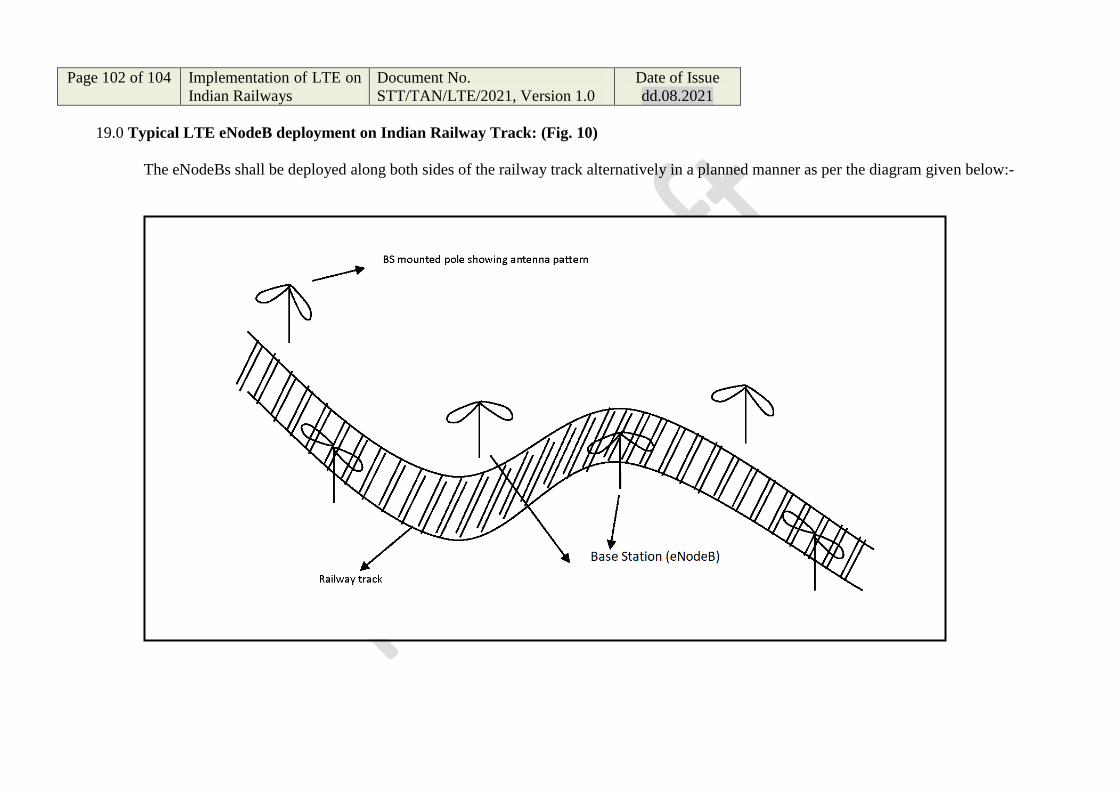
Page 102 of 104 Implementation of LTE on
Indian Railways
Document No.
STT/TAN/LTE/2021, Version 1.0 Date of Issue
dd.08.2021
19.0 Typical LTE eNodeB deployment on Indian Railway Track: (Fig. 10)
The eNodeBs shall be deployed along both sides of the railway track alternatively in a planned manner as per the diagram given below:-
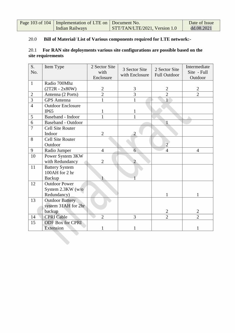
Page 103 of 104 Implementation of LTE on
Indian Railways
Document No.
STT/TAN/LTE/2021, Version 1.0
Date of Issue
dd.08.2021
20.0 Bill of Material/ List of Various components required for LTE network:-
20.1 For RAN site deployments various site configurations are possible based on the
site requirements
S.
No.
Item Type 2 Sector Site
with
Enclosure
3 Sector Site
with Enclosure
2 Sector Site
Full Outdoor
Intermediate
Site - Full
Outdoor
1 Radio 700Mhz
(2T2R - 2x80W) 2 3 2 2
2 Antenna (2 Ports) 2 3 2 2
3 GPS Antenna 1 1 1
4 Outdoor Enclosure
IP65 1 1
5 Baseband - Indoor 1 1
6 Baseband - Outdoor 1
7 Cell Site Router
Indoor 2 2
8 Cell Site Router
Outdoor 2
9 Radio Jumper 4 6 4 4
10 Power System 3KW
with Redundancy 2 2
11 Battery System
100AH for 2 hr
Backup 1 1
12 Outdoor Power
System 2.3KW (w/o
Redundancy) 1 1
13 Outdoor Battery
system 31AH for 2hr
backup 2 2
14 CPRI Cable 2 3 2 2
15 ODF Box for CPRI
Extension 1 1 1

Page 104 of 104 Implementation of LTE on
Indian Railways
Document No.
STT/TAN/LTE/2021, Version 1.0
Date of Issue
dd.08.2021
20.2 Core Network Elements (Central Data Centers)
Node Gurgaon Secunderabad Remarks
MME 1 1
New Delhi and
Secunderabad are in
Geo-Redundancy
SGW Control Plane 1 1
SGW User Plane 1 1
PGW Control Plane 1 1
PGW User Plane 1 1
PCRF 1 1
HSS 1 1
UDR 1 1
Prov Gateway 1 1
DNS 1 1
20.3 Zonal Locations
Node Railway Zonal Remarks
SGW User Plane
16
Each Railway Zone is Ge-
Redundant to peer zone
xx.xx

Annexure – 5B
TCAS
LTE Radio Modem and Protocol
Requirements

A5B.1 Introduction This document describes the LTE Radio modem requirements to be used for the
purpose of TCAS System.
A5B.2 Scope Indian Railways requires a modem-router to interface between the TCAS system
and the LTE radio system. The modem-router shall have an on-board IP services
related to train operations (CCTV, TIMS, MCPTT). It shall also be upgradable
through software to the FRMCS gateway. It shall also have facility to provide
Loco to Loco and Front to Rear communication without the involvement of EPC.
A5B.3 Over the Air Requirements
i. LTE modems Dual SIM operation on one modem card will not
provide sufficient level of redundancy.
ii. QoS on Uplink : UL QCI obeys UL TFT using Network Initiated QoS as
per 3GPP TS 24.008
iii. Operating system – Shall allow the use of a hypervisor to allows
multiple operating systems to share the hardware host.
iv. Voltage – 24vDC or 110 VDC.
v. Temperature Operating Range : -40C to +70C (+85C for 10 mins)
as per EN 50155 Tx Compliance Heat, Cold, Insulation, Shock and
Vibration: EN50155:2017 Railway Applications - Electronic
equipment used on rolling stock (EN50155: Heat, Cold, Insulation,
Vibration and Shock) EN60068-2-1, EN60068-2-2, EN60068-2-30
vi. Compliance EMC: EN50121-3-2:2017 Railway Applications -
Electromagnetic Compatibility - Part 3-2
vii. Compliance Shock and Vibration : EN 61373:2017 Railway
Applications - Rolling stock equipment – Shock and Vibration Tests.
Category 1 ; Class B
viii. Compliance : Fire Protection - EN45545-2:2015 Railway Applications
- Fire Protection on Railway Vehicles - Part 2 Requirements for Fire
Behaviour of Materials and Components
ix. Compliance to Ingress Protection IEC 60529 IP54
x. Compliance to EN55032 Electromagnetic Compatibility of
Multimedia Equipment

xi. Support MVB, RS-422, RS-485
xii. Support reception of GPS, GLONASS,
xiii. Support Software Defines LAN
xiv. Support SNMP v1/v2/v3
xv. Support EM7565 LTE module or equivalent
A5B.4 Functional Requirements: i. Each stationary TCAS shall be connected to the LTE network through
Railways’ existing OFC network. This network shall be of dual-redundant
architecture.
ii. Sufficient numbers of eNode-B are to be installed along the track side
connected through OFC network.
iii. Each TCAS loco shall have provision of LTE radio modem, to which the
Loco TCAS system is connected via IP interface.
iv. The LTE modem communicates with eNodeB on the wayside over RF.
v. The eNodeB shall communicate data from stationary TCAS to loco TCAS
based on IP address.
vi. Communication coverage shall be available throughout the length of
the track, within an overlap.
vii. The LTE coverage of neighbouring stations overlap zone shall be
sufficient enough to ensure communication even if one eNodeB fails.
viii. Stationary TCAS shall generate dynamic IP addresses to the TCAS locos
which are accessing request to stabilise communication.
ix. Stationary TCAS shall be aware of the IP addresses of all locos TCAS
system in the vicinity of station. Each loco TCAS shall periodically
communicate its position to the stationary TCAS.
x. When ever, SoS condition arises at Loco TCAS side, Loco TCAS shall send
an SoS to Stationary TCAS. Then after, Stationary TCAS can transmit the
information to all other TCAS locos in its jurisdiction through the
eNodeB.
xi. Loco TCAS shall communicate to NMS server directly through LTE
network

A5B.5 LTE Communication Protocol
A5B.5.1 Loco TCAS to Stationary TCAS lookup server Packet Structure:
Field
No
Field
Description
Field Width
(Bytes)
Comment
1 Start of Frame
(SOF)
2 0xA5CC
2 Packet Version 1 1
3 Message Type 1 0: Not used
1: Loco to Station IP Look Up
request
2: Station IP Look Up response
3: Loco to Loco exchange server
4: Loco exchange server to Loco
5: Loco to Stationary TCAS
6: Stationary TCAS to Loco
7: Loco to NMS Event
8: Loco to NMS Fault
9: NMS Acknowledgement
10: Loco to CTC
11: Loco to TSR Server
12: TSR server to Loco
4 Message Length 2 In Bytes from field “Message Type
” to “CRC”
(inclusive of both) 22 Bytes
5 Message
Sequence
2 0-65535
6 Date 3 DD/MM/YY
00-99: official year, 100-126: not
used, 127: year unknown
01-12: official month, 0,13,14:
not used, 15: month unknown
01-31: official day, 0: month
unknown
Eg: 27/04/18 → 0x1B-0x04-0x12

Field
No
Field
Description
Field Width
(Bytes)
Comment
7 Time 3 HH:MM:SS (IST time)
00-99: official year, 100-126: not
used, 127: year unknown
01-12: official month, 0,13,14:
not used, 15: month unknown
01-31: official day, 0: month
unknown
Eg: 06:36:10 → 0x06-0x24-0x0A
8 Loco ID 3 Loco ID (MSB in first byte)
9 Station ID 2 Station ID (MSB in first byte)
10 Loco Random
Number
2 MSB in first byte
A5B.5.2 Stationary TCAS Lookup Server to Loco TCAS Packet Structure:
Field No Field Description Field Width (Bytes)
Comment
1 Start of Frame (SOF)
2 0xA5CC
2 Packet Version 1 1
3 Message Type 1 0: Not used 1: Loco to Station IP Look Up request 2: Station IP Look Up response 3: Loco to Loco exchange server 4: Loco exchange server to Loco 5: Loco to Stationary TCAS 6: Stationary TCAS to Loco 7: Loco to NMS Event 8: Loco to NMS Fault 9: NMS Acknowledgement 10: Loco to CTC 11: Loco to TSR Server 12: TSR server to Loco

Field No Field Description Field Width (Bytes)
Comment
4 Message Length 2 In Bytes from field “Message Type ” to “CRC” (inclusive of both)
5 Message Sequence 2 0-65535
6 Date 3 DD/MM/YY 00-99: official year, 100-126: not used, 127: year unknown 01-12: official month, 0,13,14: not used, 15: month unknown 01-31: official day, 0: month unknown Eg: 27/04/18 → 0x1B-0x04-0x12
7 Time 3 HH:MM:SS (IST time) 00-99: official year, 100-126: not used, 127: year unknown 01-12: official month, 0,13,14: not used, 15: month unknown 01-31: official day, 0: month unknown Eg: 06:36:10 → 0x06-0x24-0x0A
8 Loco ID 3 Loco ID (MSB in first byte)
9 Station ID 2 Station ID (MSB in first byte)
10 Station IP Status 1 0: Not Available 1: IPv4 Station 2: IPv6 Station 3: UHF Station
11 Station IP Number 4/16 MSB in first byte (IPv4-4Bytes, IPv6 -16Bytes)
12 Station Port number
2 MSB in first byte
13 NMS IP Status 1 0: Not Available 1: IPv4 Station 2: IPv6 Station 3: UHF Station
14 NMS IP Number 4/16 MSB in first byte (IPv4-4Bytes, IPv6 -16Bytes)
15 NMS Port number 2 MSB in first byte

Field No Field Description Field Width (Bytes)
Comment
16 TSR IP Status 1 0: Not Available 1: IPv4 Station 2: IPv6 Station 3: UHF Station
17 TSR IP Number 4/16 MSB in first byte (IPv4-4Bytes, IPv6 -16Bytes)
18 TSR Port number 2 MSB in first byte
19 CTC IP Status 1 0: Not Available 1: IPv4 Station 2: IPv6 Station 3: UHF Station
20 CTC IP Number 4/16 MSB in first byte (IPv4-4Bytes, IPv6 -16Bytes)
21 CTC Port number 2 MSB in first byte
22 Server Random Number
2 MSB in first byte
23 MAC 2 MSB in first byte, Message type to Server Random Number, Additional fill zeros to make block multiple of 128 bits
24 CRC 4 CRC 32 bit (Polynomial EEB88320), (Message type to MAC)
A5B.5.3 Loco TCAS to Loco TCAS -Exchange Server Packet Structure:
Field No Field
Description
Field Width
(Bytes)
Comment
1 Start of Frame
(SOF)
2 0xA5CC
2 Packet Version 1 1

Field No Field
Description
Field Width
(Bytes)
Comment
3 Message Type 1 0: Not used
1: Loco to Station IP Look Up
request
2: Station IP Look Up response
3: Loco to Loco exchange server
4: Loco exchange server to Loco
5: Loco to Stationary TCAS
6: Stationary TCAS to Loco
7: Loco to NMS Event
8: Loco to NMS Fault
9: NMS Acknowledgement
10: Loco to CTC
11: Loco to TSR Server
12: TSR server to Loco
4 Message
Length
2 In Bytes from field “Message
Type ” to “CRC”
(inclusive of both)
5 Message
Sequence
2 0-65535
6 Date 3 DD/MM/YY
00-99: official year, 100-126:
not used, 127: year unknown
01-12: official month, 0,13,14:
not used, 15: month unknown
01-31: official day, 0: month
unknown
Eg: 27/04/18 → 0x1B-0x04-
0x12
7 Time 3 HH:MM:SS (IST time)
00-99: official year, 100-126:
not used, 127: year unknown
01-12: official month, 0,13,14:
not used, 15: month unknown
01-31: official day, 0: month
unknown
Eg: 06:36:10 → 0x06-0x24-0x0A
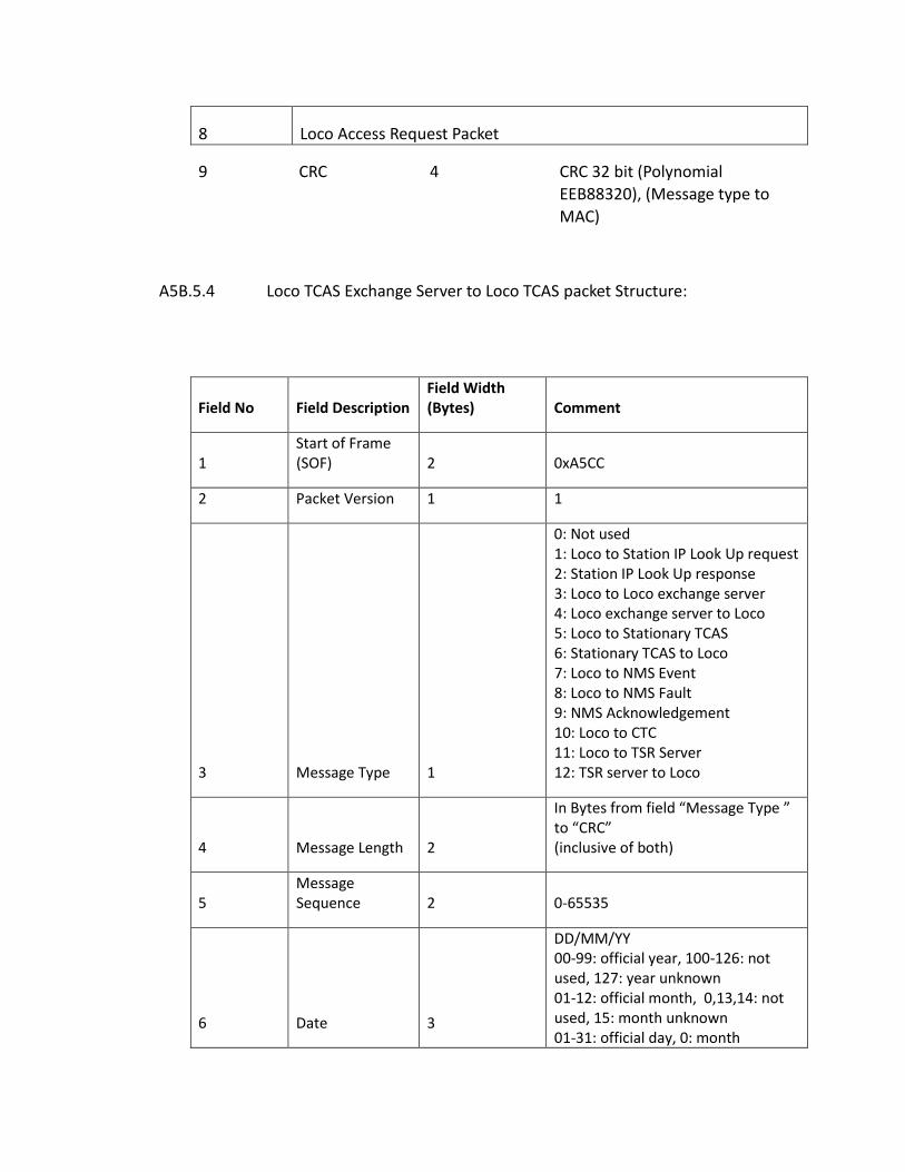
8 Loco Access Request Packet
9 CRC 4 CRC 32 bit (Polynomial
EEB88320), (Message type to
MAC)
A5B.5.4 Loco TCAS Exchange Server to Loco TCAS packet Structure:
Field No Field Description Field Width (Bytes) Comment
1 Start of Frame (SOF) 2 0xA5CC
2 Packet Version 1 1
3 Message Type 1
0: Not used 1: Loco to Station IP Look Up request 2: Station IP Look Up response 3: Loco to Loco exchange server 4: Loco exchange server to Loco 5: Loco to Stationary TCAS 6: Stationary TCAS to Loco 7: Loco to NMS Event 8: Loco to NMS Fault 9: NMS Acknowledgement 10: Loco to CTC 11: Loco to TSR Server 12: TSR server to Loco
4 Message Length 2
In Bytes from field “Message Type ” to “CRC” (inclusive of both)
5 Message Sequence 2 0-65535
6 Date 3
DD/MM/YY 00-99: official year, 100-126: not used, 127: year unknown 01-12: official month, 0,13,14: not used, 15: month unknown 01-31: official day, 0: month

Field No Field Description Field Width (Bytes) Comment
unknown Eg: 27/04/18 → 0x1B-0x04-0x12
7 Time 3
HH:MM:SS (IST time) 00-99: official year, 100-126: not used, 127: year unknown 01-12: official month, 0,13,14: not used, 15: month unknown 01-31: official day, 0: month unknown Eg: 06:36:10 → 0x06-0x24-0x0A
8 Number of Loco Packets 1
Indicate number of Loco Packets below (Max 20)
Field No Field Description Field Width (Bytes) Comment
1 Start of Frame (SOF) 2 0xA5CC
2 Packet Version 1 1
3 Message Type 1
0: Not used 1: Loco to Station IP Look Up request 2: Station IP Look Up response 3: Loco to Loco exchange server 4: Loco exchange server to Loco 5: Loco to Stationary TCAS 6: Stationary TCAS to Loco 7: Loco to NMS Event 8: Loco to NMS Fault 9: NMS Acknowledgement 10: Loco to CTC 11: Loco to TSR Server 12: TSR server to Loco
4 Message Length 2
In Bytes from field “Message Type ” to “CRC” (inclusive of both)
5 Message Sequence 2 0-65535
6 Date 3
DD/MM/YY 00-99: official year, 100-126: not used, 127: year unknown

Field No Field Description Field Width (Bytes) Comment
01-12: official month, 0,13,14: not used, 15: month unknown 01-31: official day, 0: month unknown Eg: 27/04/18 → 0x1B-0x04-0x12
7 Time 3
HH:MM:SS (IST time) 00-99: official year, 100-126: not used, 127: year unknown 01-12: official month, 0,13,14: not used, 15: month unknown 01-31: official day, 0: month unknown Eg: 06:36:10 → 0x06-0x24-0x0A
8 Number of Loco Packets 1
Indicate number of Loco Packets below (Max 20)
9 Loco Access Request Packet1
10 Loco Access Request Packet2
-
-
28 Loco Access Request Packet 20
29 MAC 2
MSB in first byte, Message type
to Server Random Number,
Additional fill zeros to make
block multiple of 128 bits
30 CRC 4 CRC 32 bit (Polynomial EEB88320), (Message type to MAC)
29 MAC 2
MSB in first byte, Message type to Server Random Number, Additional fill zeros to make block multiple of 128 bits
30 CRC 4 CRC 32 bit (Polynomial EEB88320), (Message type to MAC)
29 MAC 2
MSB in first byte, Message type to Server Random Number, Additional fill zeros to make block multiple of 128 bits
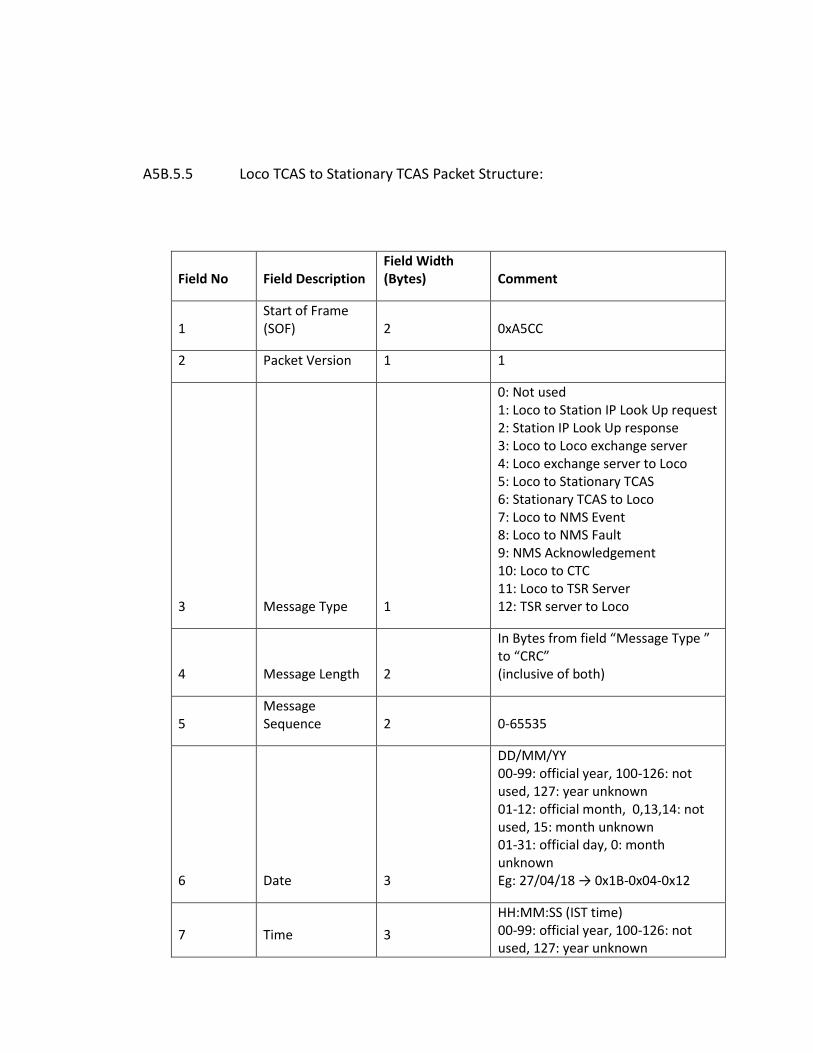
A5B.5.5 Loco TCAS to Stationary TCAS Packet Structure:
Field No Field Description Field Width (Bytes) Comment
1 Start of Frame (SOF) 2 0xA5CC
2 Packet Version 1 1
3 Message Type 1
0: Not used 1: Loco to Station IP Look Up request 2: Station IP Look Up response 3: Loco to Loco exchange server 4: Loco exchange server to Loco 5: Loco to Stationary TCAS 6: Stationary TCAS to Loco 7: Loco to NMS Event 8: Loco to NMS Fault 9: NMS Acknowledgement 10: Loco to CTC 11: Loco to TSR Server 12: TSR server to Loco
4 Message Length 2
In Bytes from field “Message Type ” to “CRC” (inclusive of both)
5 Message Sequence 2 0-65535
6 Date 3
DD/MM/YY 00-99: official year, 100-126: not used, 127: year unknown 01-12: official month, 0,13,14: not used, 15: month unknown 01-31: official day, 0: month unknown Eg: 27/04/18 → 0x1B-0x04-0x12
7 Time 3
HH:MM:SS (IST time) 00-99: official year, 100-126: not used, 127: year unknown

01-12: official month, 0,13,14: not used, 15: month unknown 01-31: official day, 0: month unknown Eg: 06:36:10 → 0x06-0x24-0x0A
8 Loco TCAS access request packet/Regular packet
9 CRC 4 CRC 32 bit (Polynomial EEB88320), (Message type to End of Loco Packet)
A5B.5.6 Stationary TCAS to Loco TCAS Packet Structure:
Field No Field Description Field Width (Bytes) Comment
1 Start of Frame (SOF) 2 0xA5CC
2 Packet Version 1 1
3 Message Type 1
0: Not used 1: Loco to Station IP Look Up request 2: Station IP Look Up response 3: Loco to Loco exchange server 4: Loco exchange server to Loco 5: Loco to Stationary TCAS 6: Stationary TCAS to Loco 7: Loco to NMS Event 8: Loco to NMS Fault 9: NMS Acknowledgement 10: Loco to CTC 11: Loco to TSR Server 12: TSR server to Loco
4 Message Length 2
In Bytes from field “Message Type ” to “CRC” (inclusive of both)
5 Message Sequence 2 0-65535
6 Date 3
DD/MM/YY 00-99: official year, 100-126: not used, 127: year unknown 01-12: official month, 0,13,14: not used, 15: month unknown
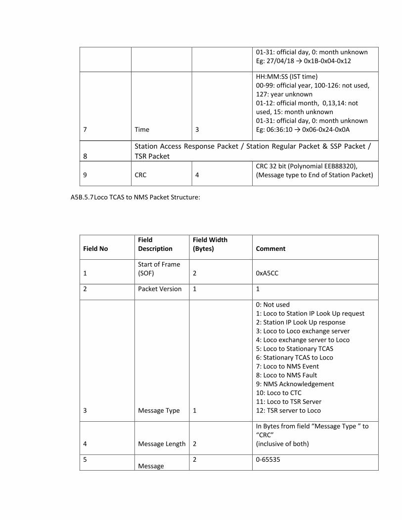
01-31: official day, 0: month unknown Eg: 27/04/18 → 0x1B-0x04-0x12
7 Time 3
HH:MM:SS (IST time) 00-99: official year, 100-126: not used, 127: year unknown 01-12: official month, 0,13,14: not used, 15: month unknown 01-31: official day, 0: month unknown Eg: 06:36:10 → 0x06-0x24-0x0A
8
Station Access Response Packet / Station Regular Packet & SSP Packet /
TSR Packet
9 CRC 4 CRC 32 bit (Polynomial EEB88320), (Message type to End of Station Packet)
A5B.5.7 Loco TCAS to NMS Packet Structure:
Field No Field Description
Field Width (Bytes) Comment
1 Start of Frame (SOF) 2 0xA5CC
2 Packet Version 1 1
3 Message Type 1
0: Not used 1: Loco to Station IP Look Up request 2: Station IP Look Up response 3: Loco to Loco exchange server 4: Loco exchange server to Loco 5: Loco to Stationary TCAS 6: Stationary TCAS to Loco 7: Loco to NMS Event 8: Loco to NMS Fault 9: NMS Acknowledgement 10: Loco to CTC 11: Loco to TSR Server 12: TSR server to Loco
4 Message Length 2
In Bytes from field “Message Type ” to “CRC” (inclusive of both)
5 Message
2 0-65535
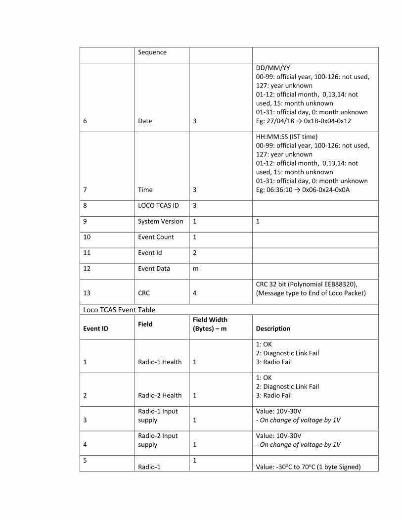
Sequence
6 Date 3
DD/MM/YY 00-99: official year, 100-126: not used, 127: year unknown 01-12: official month, 0,13,14: not used, 15: month unknown 01-31: official day, 0: month unknown Eg: 27/04/18 → 0x1B-0x04-0x12
7 Time 3
HH:MM:SS (IST time) 00-99: official year, 100-126: not used, 127: year unknown 01-12: official month, 0,13,14: not used, 15: month unknown 01-31: official day, 0: month unknown Eg: 06:36:10 → 0x06-0x24-0x0A
8 LOCO TCAS ID 3
9 System Version 1 1
10 Event Count 1
11 Event Id 2
12 Event Data m
13 CRC 4 CRC 32 bit (Polynomial EEB88320), (Message type to End of Loco Packet)
Loco TCAS Event Table
Event ID Field
Field Width (Bytes) – m Description
1 Radio-1 Health 1
1: OK 2: Diagnostic Link Fail 3: Radio Fail
2 Radio-2 Health 1
1: OK 2: Diagnostic Link Fail 3: Radio Fail
3 Radio-1 Input supply 1
Value: 10V-30V - On change of voltage by 1V
4 Radio-2 Input supply 1
Value: 10V-30V - On change of voltage by 1V
5 Radio-1
1 Value: -30oC to 70oC (1 byte Signed)

Temperature - On change of temperature by 3oC
6 Radio-2 Temperature 1
Value: -30oC to 70oC (1 byte Signed) - On change of temperature by 3oC
7 Radio-1 PA Temperature 1
Value:20oC to 100oC - On change of temperature by 3oC
8 Radio-2 PA Temperature 1
Value:20oC to 100oC - On change of temperature by 3oC
9 Radio-1 PA Supply Voltage 1
Value: 11V-13V - On change of voltage by 1V
10 Radio-2 PA Supply Voltage 1
Value: 11V-13V - On change of voltage by 1V
11 Radio-1 Tx PA Current 1
Value: 1.5A to 3.2A - On change of current
12 Radio-2 Tx PA Current 1
Value: 1.5A to 3.2A - On change of current
13 Radio-1 Reverse Power 1
Value received from Radio Eg: Value received from Radio is 0x01 = 0.1W (Value: 0x01)
14 Radio-2 Reverse Power 1
Value received from Radio Eg: Value received from Radio is 0x0F = 1.5W (Value: 0x0F)
15 Radio-1 Forward Power 1
Value received from Radio Eg: Value received from Radio is 0x36 = 5.4W (Value: 0x36)
16 Radio-2 Forward Power 1
Value received from Radio Eg: Value received from Radio is 0x78 = 12W (Value: 0x78)
17 Radio-1 RSSI 2
Value received from Radio Eg: Value received from Radio is 0xBDBF = -132.5dBm (Value: 0xBDBF)
18 Radio-2 RSSI 2
Value received from Radio Eg: Value received from Radio is 0xBDBF = -132.5dBm (Value: 0xBDBF)
19 Stationary Regular packet
2 0-2000 ms

received time offset
20 Active GPS Number 1
Gps used for frame number calculation 0 – No Active GPS 1 – GPS 1 2 – GPS 2 3 – Both GPS - on change of GPS
21 GPS-1 View Status 1
0 – No Data 1 – V 2 – A - on detection of change of event
22 GPS-2 View Status 1
0 – No Data 1 – V 2 – A - on detection of change of event
23 GPS-1 Seconds 1 0 to 59 seconds - on change of value
24 GPS-2 Seconds 1 0 to 59 seconds - on change of value
25 GPS-1 Satellites in View 1
Value received from GPS receiver - On change of value
26 GPS-1 CNO (Max) 1
Maximum CNO Value received from GPS receiver - On change of value
27 GPS-2 Satellites in View 1
Value received from GPS receiver - On change of value
28 GPS-2 CNO (Max) 1
Maximum CNO Value received from GPS receiver - On change of value
29 GPS-1 link status 2
0-Both GPS link and PPS fail 1- GPS link fail and PPS ok 2- GPS link ok and PPS fail 3- GPS link ok and PPS ok
30 GPS-2 link status 2
0-Both GPS link and PPS fail 1- GPS link fail and PPS ok 2- GPS link ok and PPS fail 3- GPS link ok and PPS ok

31 GSM-1 RSSI 1 Value received from GSM module - On change of value
32 GSM-2 RSSI 1 Value received from GSM module - On change of value
33 Current Running Key 1
0: Default key set, 1-30: KMS key set - on change of Key Set
34 Remaining Number of Keys 1
0: No keys, 1-30: Remaining KMS key sets - on change of value
35
Session Key
Checksum 2
Checksum of 16 bytes session key
- for every 2s at the time of
Authentication only
36
DMI-1 link
status 2
0-NOT OK
1-OK
37
DMI-2 link
status 2
0-NOT OK
1-OK
38
RFID Reader-
1 link status 2
0-NOT OK
1-OK
39
RFID Reader-
2 link status 2
0-NOT OK
1-OK
40
Duplicate
Missing RFID
Tag 2 RFID Tag Number
41
Missing
linked RFID
Tag 4
B3-B1: Linked RFID Tag
B0: Linking direction
42
Computed
TLM Status 4
B3-B1: Station Id
B0: TLM Status
Values:
1 – TLM Updated
2 – TLM Timeout
43
Train
Configuration 1
0 – No Change
1 – Updated
44
Train Brakes
Test 1
0 – Brake Test failed
1 – Brake Test Successful
45
Selected
Train
formation 1 TBD
46 Selected Cab 1 1 – Cab1 Selected

2 – Cab2 Selected
47
Brake
application
reason 1
0-Not used
1-Reverse movement detected
2-Side collision detected
3-Overspeed
4-Rollback detected
5-MBT selected
6- No LP Acknowledge
7- MA Shortened
8-Headon collision detected
9-Rearend collision detected
10-Loco Specific SoS received
11-Station General SoS received
48
Station
General SoS 3
B2-B1: Station Id
B0: General SoS status (1 –
Received, 2 – Cancelled)
49
Station Loco
Specific SoS 3
B2-B1: Station Id
B0: Specific SoS status (1 –
Received, 2 – Cancelled)
50
Collision
Detection 4
B3-B1: Loco Id
B0: SoS code
Values:
1 – Manual SoS received
2 – Manual SoS cancelled
3 – Side collision detected
4 – Side collision end
5 – Head-on collision detected
6 – Head-on collision end
7 – Rear-end collision detected
8 – Rear-end collision end
51 Loco Self SoS 1
1 – Manual SoS
2 – Manual SoS end
3 – Side Collision start
4 – Side Collision end
52
TCAS
Connection 1
1 – TCAS Isolated
2 – TCAS Connected
53 BIU Isolated 1
1 – BIU Isolated
2 – BIU Connected
54 EB Bypassed 1
1 – EB Connected
2 – EB Bypassed
55
TCAS
Territory 1
1 – TCAS Entry
2 – TCAS Exit

56-199 Reserved
200-254
Firm specific
events 2
This field Information is specific to
TCAS firm
255 Specific value Not to be used
A5B.5.8 Loco to NMS Fault Packet Structure :
Field No Field Description
Field Width (Bytes) Comment
1 Start of Frame (SOF) 2 0xA5CC
2 Packet Version 1 1
3 Message Type 1
0: Not used 1: Loco to Station IP Look Up request 2: Station IP Look Up response 3: Loco to Loco exchange server 4: Loco exchange server to Loco 5: Loco to Stationary TCAS 6: Stationary TCAS to Loco 7: Loco to NMS Event 8: Loco to NMS Fault 9: NMS Acknowledgement 10: Loco to CTC 11: Loco to TSR Server 12: TSR server to Loco
4 Message Length 2
In Bytes from field “Message Type ” to “CRC” (inclusive of both)
5 Message Sequence 2 0-65535
6 Date 3
DD/MM/YY 00-99: official year, 100-126: not used, 127: year unknown 01-12: official month, 0,13,14: not used, 15: month unknown 01-31: official day, 0: month unknown Eg: 27/04/18 → 0x1B-0x04-0x12
7 Time 3 HH:MM:SS (IST time) 00-99: official year, 100-126: not

Field No Field Description
Field Width (Bytes) Comment
used, 127: year unknown 01-12: official month, 0,13,14: not used, 15: month unknown 01-31: official day, 0: month unknown Eg: 06:36:10 → 0x06-0x24-0x0A
8 TCAS subsystem type 1
0x11 – Stationary TCAS 0x22 – Loco TCAS 0x33 – TSRMS
9 TCAS Subsystem ID 3
10 System Version 1 1
11 Total Fault Codes (F) 1 Max number of faults shall be 10
12 Fault Code 2*F Firm specific code to be decoded by NMS
13 CRC 4
CRC 32 bit (Polynomial EEB88320), (Message type to End of Loco Packet)
A5B.5.9 NMS Acknowledgment Packet Structure:
Field No Field Description
Field Width (Bytes) Comment
1 Start of Frame (SOF) 2 0xA5CC
2 Packet Version 1 1
3 Message Type 1
0: Not used 1: Loco to Station IP Look Up request 2: Station IP Look Up response 3: Loco to Loco exchange server
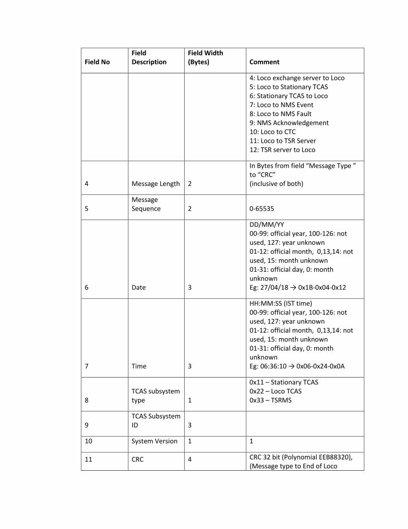
Field No Field Description
Field Width (Bytes) Comment
4: Loco exchange server to Loco 5: Loco to Stationary TCAS 6: Stationary TCAS to Loco 7: Loco to NMS Event 8: Loco to NMS Fault 9: NMS Acknowledgement 10: Loco to CTC 11: Loco to TSR Server 12: TSR server to Loco
4 Message Length 2
In Bytes from field “Message Type ” to “CRC” (inclusive of both)
5 Message Sequence 2 0-65535
6 Date 3
DD/MM/YY 00-99: official year, 100-126: not used, 127: year unknown 01-12: official month, 0,13,14: not used, 15: month unknown 01-31: official day, 0: month unknown Eg: 27/04/18 → 0x1B-0x04-0x12
7 Time 3
HH:MM:SS (IST time) 00-99: official year, 100-126: not used, 127: year unknown 01-12: official month, 0,13,14: not used, 15: month unknown 01-31: official day, 0: month unknown Eg: 06:36:10 → 0x06-0x24-0x0A
8 TCAS subsystem type 1
0x11 – Stationary TCAS 0x22 – Loco TCAS 0x33 – TSRMS
9 TCAS Subsystem ID 3
10 System Version 1 1
11 CRC 4 CRC 32 bit (Polynomial EEB88320), (Message type to End of Loco

Field No Field Description
Field Width (Bytes) Comment
Packet)
A5B.5.10 Loco TCAS to CTC Packet Structure:
Field No Field Description
Field Width (Bytes) Comment
1 Start of Frame (SOF) 2 0xA5CC
2 Packet Version 1 1
3 Message Type 1 0: Not used 1: Loco to Station IP Look Up request 2: Station IP Look Up response 3: Loco to Loco exchange server 4: Loco exchange server to Loco 5: Loco to Stationary TCAS 6: Stationary TCAS to Loco 7: Loco to NMS Event 8: Loco to NMS Fault 9: NMS Acknowledgement 10: Loco to CTC 11: Loco to TSR Server 12: TSR server to Loco
4 Message Length 2
In Bytes from field “Message Type ” to “CRC” (inclusive of both)
5 Message Sequence 2 0-65535
6 Date 3
DD/MM/YY 00-99: official year, 100-126: not used, 127: year unknown 01-12: official month, 0,13,14: not used, 15: month unknown 01-31: official day, 0: month unknown

Field No Field Description
Field Width (Bytes) Comment
Eg: 27/04/18 → 0x1B-0x04-0x12
7 Time 3
HH:MM:SS (IST time) 00-99: official year, 100-126: not used, 127: year unknown 01-12: official month, 0,13,14: not used, 15: month unknown 01-31: official day, 0: month unknown Eg: 06:36:10 → 0x06-0x24-0x0A
8 Train Position to CTC
9 CRC 4 CRC 32 bit (Polynomial EEB88320), (Message type to End of Loco Packet)
A5B.5.11 Loco TCAS to TSR Server:
Field No Field
Description
Field Width
(Bytes)
Comment
1 Start of
Frame (SOF)
2 0xA5CC
2 Packet
Version
1 1
3 Message
Type
1 0: Not used
1: Loco to Station IP Look Up
request
2: Station IP Look Up response
3: Loco to Loco exchange server
4: Loco exchange server to Loco
5: Loco to Stationary TCAS
6: Stationary TCAS to Loco
7: Loco to NMS Event
8: Loco to NMS Fault
9: NMS Acknowledgement
10: Loco to CTC
11: Loco to TSR Server
12: TSR server to Loco
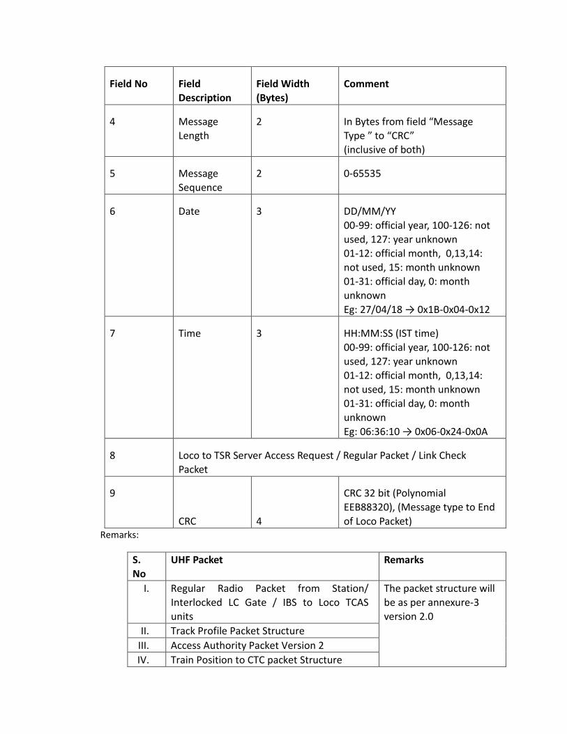
Field No Field
Description
Field Width
(Bytes)
Comment
4 Message
Length
2 In Bytes from field “Message
Type ” to “CRC”
(inclusive of both)
5 Message
Sequence
2 0-65535
6 Date 3 DD/MM/YY
00-99: official year, 100-126: not
used, 127: year unknown
01-12: official month, 0,13,14:
not used, 15: month unknown
01-31: official day, 0: month
unknown
Eg: 27/04/18 → 0x1B-0x04-0x12
7 Time 3 HH:MM:SS (IST time)
00-99: official year, 100-126: not
used, 127: year unknown
01-12: official month, 0,13,14:
not used, 15: month unknown
01-31: official day, 0: month
unknown
Eg: 06:36:10 → 0x06-0x24-0x0A
8 Loco to TSR Server Access Request / Regular Packet / Link Check
Packet
9
CRC 4
CRC 32 bit (Polynomial
EEB88320), (Message type to End
of Loco Packet) Remarks:
S.
No
UHF Packet Remarks
I. Regular Radio Packet from Station/
Interlocked LC Gate / IBS to Loco TCAS
units
The packet structure will
be as per annexure-3
version 2.0
II. Track Profile Packet Structure
III. Access Authority Packet Version 2
IV. Train Position to CTC packet Structure

V. Station to Loco Regular Packet Structure
VI. Access Request Packet
VII. Train Event data to NMS Packet Structure