Experimental Verification of Hyde System - IIT Kanpur · 2004-07-13 · EXPERIMENTAL VERIFICATION...
15
13 th World Conference on Earthquake Engineering Vancouver, B.C., Canada August 1-6, 2004 Paper No. 3163 EXPERIMENTAL VERIFICATION OF HYDE SYSTEM Katrin SCHMIDT 1 , Uwe E. DORKA 2 SUMMARY Within the DISPASS project a 3-story full-scale reinforced concrete frame and a 1:2 scale steel frame retrofitted with HYDE Systems were tested at the reaction wall at the European Laboratory of Structural Assessment (ELSA). Two possibilities to construct a HYDE System are shown with the structures. The earthquake tests were performed by means of the Pseudo-Dynamic (PsD) test method. This paper presents the test results and a comparison with numerical studies. They verify the basic modelling approach for HYDE-systems. The superior behaviour of the HYDE system was demonstrated in the tests where a significant reduction of forces and displacements was achieved. INTRODUCTION Earthquake protection of existing buildings is existential in many countries. Passive control concepts offer advanced retrofitting strategies. Within the DISPASS project financed under the ECOLEADER contract within the Fifth Framework Program of the European Commission, the Base Isolation, added damping systems and the Hysteretic Device (HYDE) System were investigated. This paper deals with the HYDE System, which has been studied extensively [1, 2, 3] and has been applied in a building in Seattle, USA [4]. This previous work showed the efficiency of the HYDE system. It is a cost effective advanced technique for implementing retrofitting strategies of building structures. A numerical modelling approach has emerged that allows fast and efficient response simulations. A full-scale reinforced concrete (RC) frame with masonry infill and a 1:2 scale steel moment resisting frame were retrofitted. These structures were investigated experimentally using the reaction wall of the ELSA laboratory. The choice of two different structures allowed to investigate possible differences in implementation and efficiency. The earthquake tests were performed by means of the Pseudo-Dynamic (PsD) test method [5] using different ground acceleration time histories. This paper presents the test results and a comparison with numerical studies. It is known that not only a good numerical model, but also correct structural detailing is fundamental for the functioning of a HYDE system, where a special mechanism is introduced into the structure. The way to correctly design and implement a HYDE System is shown. 1 PhD Student, University of Kassel, Germany, Email: [email protected] 2 Prof. Dr.-Ing., University of Kassel, Germany, Email: [email protected]
Transcript of Experimental Verification of Hyde System - IIT Kanpur · 2004-07-13 · EXPERIMENTAL VERIFICATION...

13th World Conference on Earthquake Engineering Vancouver, B.C., Canada
August 1-6, 2004 Paper No. 3163
EXPERIMENTAL VERIFICATION OF HYDE SYSTEM
Katrin SCHMIDT1, Uwe E. DORKA2
SUMMARY Within the DISPASS project a 3-story full-scale reinforced concrete frame and a 1:2 scale steel frame retrofitted with HYDE Systems were tested at the reaction wall at the European Laboratory of Structural Assessment (ELSA). Two possibilities to construct a HYDE System are shown with the structures. The earthquake tests were performed by means of the Pseudo-Dynamic (PsD) test method. This paper presents the test results and a comparison with numerical studies. They verify the basic modelling approach for HYDE-systems. The superior behaviour of the HYDE system was demonstrated in the tests where a significant reduction of forces and displacements was achieved.
INTRODUCTION Earthquake protection of existing buildings is existential in many countries. Passive control concepts offer advanced retrofitting strategies. Within the DISPASS project financed under the ECOLEADER contract within the Fifth Framework Program of the European Commission, the Base Isolation, added damping systems and the Hysteretic Device (HYDE) System were investigated. This paper deals with the HYDE System, which has been studied extensively [1, 2, 3] and has been applied in a building in Seattle, USA [4]. This previous work showed the efficiency of the HYDE system. It is a cost effective advanced technique for implementing retrofitting strategies of building structures. A numerical modelling approach has emerged that allows fast and efficient response simulations. A full-scale reinforced concrete (RC) frame with masonry infill and a 1:2 scale steel moment resisting frame were retrofitted. These structures were investigated experimentally using the reaction wall of the ELSA laboratory. The choice of two different structures allowed to investigate possible differences in implementation and efficiency. The earthquake tests were performed by means of the Pseudo-Dynamic (PsD) test method [5] using different ground acceleration time histories. This paper presents the test results and a comparison with numerical studies. It is known that not only a good numerical model, but also correct structural detailing is fundamental for the functioning of a HYDE system, where a special mechanism is introduced into the structure. The way to correctly design and implement a HYDE System is shown.
1 PhD Student, University of Kassel, Germany, Email: [email protected] 2 Prof. Dr.-Ing., University of Kassel, Germany, Email: [email protected]

PRINCIPLE OF HYDE SYSTEM Structural Principle The HYDE System concept was first introduced by Dorka [1]. It consists of two structural parts: a very stiff Primary Horizontal load bearing System (PHS) with Seismic Links (SLs) where HYsteretic DEvices (HYDEs) are placed and a conventional soft Secondary Horizontal load bearing System (SHS). The PHS must be very stiff in order to concentrate horizontal displacements in the seismic links, where the HYDEs dissipate most of the input energy. Many inexpensive devices which have been investigated and tested can be used as HYDEs [1]. The HYDEs must show almost ideal stiff-elastic-plastic behaviour to dissipate a large amount of input energy. The SLs can transmit only the maximum HYDE force as storey shear to the adjacent structural members. Therefore the remaining elastic part of the structure is protected from overloading. This unique feature of the HYDE System concept allows the designer to choose a shear force envelope that is suitable for the structure and design its conventional members accordingly. The remaining task is to verify the displacement capabilities of the chosen mechanism, e.g. in the locations of the seismic links. The design limit of the HYDE System is defined by the elastic deformation limit of the SHS, usually columns in the storey where the SL is placed.
SL with HYDEs
PHS
SHS
Figure 1: HYDE System with single SL in the ground floor
The SHS must stabilise this mechanism with respect to the P- ∆ effect. It should be stiff enough to perform this task. But any additional stiffness of the SHS will draw energy away from the PHS causing un-necessary stresses. A correctly conceived HYDE System has a clearly defined stiff-ductile mechanism where the kinetic energy in the structure is minimized, thus minimizing deformations and stresses. A well-designed HYDE system dissipates approximately 85% of the input energy in its HYDEs. The result is a combination of the advantages of a stiff non-ductile system with a soft ductile system: small displacements and small forces. Linear behaviour of the conventional part of the structure even under serve earthquakes is achieved. Numerical Modeling First, a detailed numerical model is generated for the conventional structure using only linear elements for columns, beams, floors and walls. This follows the structural principle of the HYDE-System that all structural members, except the HYDEs, remain elastic. Then, static condensation is performed. The choice on the number of condensed degrees-of-freedom (DOF) is a trade-off between accuracy and calculation time. With typical building structures, 3DOFs per floor (2 horizontal, one in-plane rotational) are usually sufficient for accuracy and allow very fast simulations.
PHS (primary horizontal system) SHS (secondary horizontal system) SL (seismic link) HYDE (hysteretic device)

To describe the behaviour of the seismic links with their HYDEs, a Bouc-Wen type hysteresis law [6] is used to describe the shear force transmitted through each SL. This law is numerically quite stable, which is a necessity when analysing stiff-ductile systems. Design Approach To find the required HYDE System parameters, especially the yield force and stiffness of the SLs, a large initial stiffness is first selected. It is known from many studies that a very large initial stiffness has no effect on the storey drift. Maximum link displacements are then calculated for selected link yield forces by time history analysis and the results plotted in a diagram (Figure 2). There, a design point is defined by the previously discussed displacement limit of the SL giving the design link force. The design curve is limited by two elastic systems marked I and II in Figure 2. System I is characterized by a stiff elastic behaviour in the SL (no inelastic HYDE behaviour), resulting in maximum forces and minimum displacements. The other system is characterized by the absence of HYDEs in the SL. This results in minimum forces (the SHS is practically acting alone in the SL) but exaggerated displacements. The location of the design point on this curve gives an idea of the efficiency of the selected system in terms of reducing forces and displacements. After the design link force is selected, a stiffness variation in the link is performed to determine the lower limit (what is “stiff enough”) and arrive at a cost effective stiffening system for the PHS. The design process for retrofitting buildings with a HYDE System is described in detail in [7, 8].
Figure 2: Design curve
INVESTIGATION ON STEEL FRAME MOCK-UP Description of the mock-up The design of the steel frame mock up was based on a full-scale two-storey one-bay moment resisting steel frame previously tested at ELSA laboratory [9], representative of an industrial building. The structure used for retrofitting with the HYDE system was a 1:2 scale model with two bays and three stories. The geometry of the structure consisted of 4m and 2.8m beams in the longitudinal (test direction) and transverse directions respectively, with inter-storey heights of 2m. The structure was braced in the transverse direction and was constructed with HEB140 columns and steel-concrete-composite slabs connected with headed shear studs to IPE180 steel beams. The beam-column connections were welded. For details on this structure, see the technical drawings in [10].

Together with the seismic actions, a live load corresponding to a distributed load of 5kN/m2 reduced by a factor of 1/3 was considered. The dead load was taken as 2.5kN/m2. The steel frame had already undergone severe testing before the DISPASS project under the BASILICATA [JRC Contract No 11897-96-05 T2PC ISP I and Basilicata Region Prot. N. 142/A3-4 of 14 Jan. 1997] project. The welding was repaired after these tests. Furthermore, the beam-column connections were reduced to a pure steel connection by cutting away the composite floor. This led to a slightly softer connection than in a real building. The first three eigenfrequencies in the excitation direction were obtained by hammer test at the end of all testing campaigns. They were 3.08Hz, 10.14Hz and 18.64Hz, respectively. Structural implementation of the HYDE System The upper floors were stiffened with diagonals to provide the required rigid block behaviour. To avoid any movement, all connections were welded. The SL was placed in the ground floor. The HYDEs were placed between stiff diagonals and the beam of the 1st storey (Figure 3). The diagonals were chosen as 2xU80 according to the stiffness requirements for the SL resulting from the numerical studies. As HYDEs, low cost Shear Panel Devices (SPDs) were used. They are made of mild steel to provide a large displacement capacity under extensive yielding. The SPD was designed with a maximum shear displacement of 5 mm. The yielding force can be calculated with the formula given below with h as SPD height, where the first term gives the web yielding and the second term represents the flange mechanism. A detailed numerical study of the shear panel was performed with ANSYS [3] which verified this simple formula.
⋅+⋅⋅=
h
tbhtfF flangeweb
yy
2
3
The HYDE connections should be designed to prevent any slag between the connected components and at the same time allow their eventual replacement. All connections were designed by static methods using the desired maximum SL force of 40kN with a safety factor of 2. This large factor was used since no data was available to determine a precise deviation from the maximum design SPD force. Initially, pre-stressed bolted connections were used, but after differential movements were recorded during the calibration tests, all connections were subsequently welded for the earthquake simulation tests.
Figure 3: HYDE System applied to the steel fame with SPD as HYDE shown in detail
Numerical Studies The structure was modelled in 2D using the program Slang [11], considering symmetry and loading direction. The linear FE-model was verified by calibration tests on the bare frame before changing the structure to a HYDE System. Additional linear elements were then added to stiffen the model in upper stories. One condensation node with one DOF (displacement in excitation direction) was introduced in each floor (see black circles in Figure 4). After static condensation, the hysteretic law was introduced between the foundation and the dynamic DOF of the 1st floor (schematically shown in Figure 4).
Figure 4: 2-D FE-model for the steel frame with stiffened upper stories, condensation nodes and
hysteretic element Earthquake-loading The earthquake loading was represented by a synthetic acceleration time history with a response spectrum compatible with Eurocode 8 [12] at 2% damping for stiff soils and a peak ground acceleration of 0.30g. The strong motion phase of the Kocaeli earthquake, scaled to the same peak acceleration, was also chosen to include a natural Mediterranean event in the study and because of its higher spectral accelerations in the low frequency range due to the near field event characteristic. Experiments The horizontal forces were imposed by means of two hydraulic actuators at each floor, attached at the edge of the structure. Each actuator was equipped with a load cell and a displacement transducer. Additional displacement transducers attached to an independent reference frame were also used. To evaluate the performance of the HYDE system, local displacement transducers were placed on the SPDs to measure the relative displacements. Rotations of the SPD were determined with two inclinometers. Details can be found in [10]. At first, the verification of the hysteretic loop of the SL in the numerical model were verified by cyclic sine wave characterisation tests starting with small amplitudes in the linear range of the SPD and increasing up to 200% of design displacement. One set of SPDs was repeatedly tested and was subjected to a number of severe cycles much higher than what could be expected during a single earthquake, including its aftershocks. The number of cycles was 54, increasing from 0.2mm to 10mm. Some cyclic deterioration of the hysteretic loop was observed due to cyclic-plastic buckling and cracking of the welds. However, no complete failure (device de-integration) of the device was observed. The maximum elastic deformation of the SL was determined at 1.2mm (Figure 5). This includes the elastic deformation of diagonals, connections and SPD. The SPD force was deduced from the test results by subtracting the base shear of the bare frame from the base shear of the frame with SPD. From these results, the maximum HYDE force was determined to 43.5kN

-80
-60
-40
-20
0
20
40
60
80
-15 -10 -5 0 5 10 15
Frame IS Drift [mm]
SP
D F
orce
[kN
]
Figure 5: SL hysteretic calibration tests with dotted lines that mark the initial and post yield
stiffness of the SPD The SPD showed cyclic plastic buckling behaviour for amplitudes exceeding about ±10mm (twice the design value), with cracks developing and growing in the welds between the web and the flange. For this reason, the stiffness and maximum HYDE force started to decrease. However, considering that the SPD hysteretic behaviour stabilized, the same set of SPDs was also used for the first earthquake simulations (PSD tests). Earthquake tests The same set of SPDs from the calibration tests was used and was welded at their connections. At this point, it was uncertain that the SPD would survive an earthquake with a maximum acceleration of 0.3g and another one with 0.45g, without completely loosing its stability. The effect of the HYDE System with a pre-damaged SPD was therefore demonstrated immediately under a 150% design earthquake with peak ground accelerations of 0.45g.
0 1 2 3 4 5 6 7 8-5
-4
-3
-2
-1
0
1
2
3
4
5
I-S Drift Displacement (mm)
Figure 6: Inter-storey drift [mm] vs. time [s] (1st floor: blue, 2nd floor: red, 3rd floor: green)

Figure 6 shows the inter-storey drifts of the 3-storey frame for the 0.45g EC8 compatible synthetic earthquake. The reduction of the inter-storey drifts in the upper floors is evident. Although the reduction in drift is compatible and expected for a solution where the upper stories are braced, it is at the first storey where the reduction in displacement is more significant, since it is here that most of the displacements are concentrated (SL) and where a large amount of energy is dissipated by the SPDs. During the earthquake simulations, the SPD webs showed increased cyclic plastic buckling and additional cracks developed at the welded device connections, but the hysteretic loops remained stable. Therefore, the SPDs were left in place for the simulation of the strong motion phase of the Kocaeli earthquake. Again, the HYDE system proved its ability to reduce the inter-storey drifts and the SPDs confirmed their superior performance and robustness. Discussion of results and comparison with numerical studies The conversion of the bare steel frame to a HYDE System was performed without any particular difficulties. The upper stories were blocked with diagonal bracings. By doing this, the displacements were concentrated, as desired, in the SL at the ground floor, where by means of low cost SPDs most of the input energy was dissipated by plastic yielding. The observed cyclic plastic buckling of the SPD webs and the weld cracking that occurred at displacements exceeding the device design displacement did not, in practice, change the beneficial behaviour of the HYDE system. Therefore, it can be concluded that SPDs are particularly suited as HYDEs for such systems. The welded connection of the SPD and the stiff diagonals lead to the required initial stiffness within the SL. Further considerations are needed here for achieving an optimum design of the diagonal and its connections. A configuration that allows an easy change of the SPD after an earthquake is needed. The energy balance (Figure 7) shows the large amount of energy dissipated by the HYDEs. During both earthquakes, the HYDE dissipates approximately 85% of the input energy. The kinetic energy is almost negligible: The system does not vibrate but moves almost as a rigid body in the SL. This reduces displacements and forces in the structure.
Total HYDE potential kinetic viscous
Figure 7: Energies over time of steel frame modified to HYDE-System under Kocaeli (left) and EC8
(right) earthquakes Figure 8 shows the very good agreement of numerical and experimental results for the earthquake simulations. Minor differences can be attributed to the observed changes in the SPDs’ hysteric loops during the PSD-test. Thus, the tests proved the validity of the HYDE System concept and its numerical model: The conventional structure remains in the elastic range and non-linear behaviour is confined to the SL only. Static condensation of the model to one master DOF in each floor and a simple hysteretic model to represent the non-linear action of the SLs proved to be sufficient for modelling this structure and perform time history analysis in an efficient way.

-5
-4
-3
-2
-1
0
1
2
3
4
5
0 2 4 6 8
Time [s]
Inte
r-st
orey
drif
t of g
roun
d flo
or [m
m]
PSD test
SLang
Figure 8: Comparison of test and numerical results
The advantages of using a HYDE System are clearly demonstrated by these tests. The drastic reduction in displacements, small forces in the device and a linear behaviour of the conventional structure are achieved with a minimum of structural changes, even to an existing structure. Furthermore, the system was very robust. It was still functioning well for a 150% design level earthquake although the SPDs had been previously damaged.
INVESTIGATION ON RC FRAME MOCK-UP Description of the mock-up The test specimen was designed according to the 1986 Italian seismic code [13]. The structure is a three-storey two-bay building with spans of 6m and 4m in the testing direction and a clear storey height of 2.70m. The transverse direction is 5.70m. The floors are hollow-clay slabs with 4cm concrete topping and a total thickness of 24cm. To reduce the thickness of the floor system, the floor beams have the same thickness and are integrated into the slabs. They have a width of 1m. The columns have a square cross section of 40cm. The beam-to-column connections do not provide adequate structural integrity under earthquake loading since only a few rebars pass through the joints and there is an eccentricity of 20cm between beam and column axes. Typical construction materials (C25/30 concrete and 440N/mm2 yield stress rebars) were used. An additional dead load was taken into account with 2kN/m2 at each floor. The live load of 2kN/m2 was reduced by a factor of 2 for both lower floors according to EC8. The self-weight of the slab is 3.5kN/m2. This results in an inertial mass of 53090kg for the 3rd storey and 50630kg for the 2nd and 1st stories, which were used in the numerical analysis and for the PsD tests. The structure was designed as a housing unit located in an area of medium seismicity (base shear coefficient 0.07, importance factor 1.0). The building showed some minor damage during testing under the BASILICATA program [13]. Also, while using the mock-up to study the effects of visco-elastic dampers within this ECOLEADER project, the elastic limit of the structure was exceeded. This led to changes in the structural properties, as evidenced by the decrease of the eigenfrequencies. The first three eigenfrequencies changed from 2.30Hz, 6.48Hz and 9.57Hz for the undamaged state to 1.3Hz, 4.81Hz and 6.83Hz before the building was modified to a HYDE system.

Structural implementation of the HYDE System Very often, open spaces for parking or commercial use are found at the ground floor of residential buildings, with the upper floors substantially stiffened by masonry partition walls of the apartments. This creates a soft storey in the ground floor which often fails during an earthquake. However, considering that the upper floors constitute a rigid block relative to the ground floor, such buildings lend themselves easily to the HYDE System concept: They already possess an SL in the ground floor to be equipped with HYDEs. Thus, with very little interference, a HYDE System with one SL can be implemented. Although in most residential buildings the upper stories are in-filled, this was not the case for the test structure, therefore masonry walls still had to be added. These were placed only in the short span bays, with the consequence that realistic stiffening was not achieved (see Figure 10). In addition, stiffening both bays would have caused control problems during the PsD tests and the capacity of the actuators would have been exceeded. Window openings were placed in the masonry walls of the third storey to study, if cracks in the corners of windows would lead to secondary failures of the walls.
Figure 9: HYDE system applied to a RC frame mock-up: New masonry walls in the small bays of the upper stories with window openings on top storey. Prefabricated concrete walls with friction
devices in the small bays of the ground floor serving as seismic link. Stiff concrete walls with friction devices were used in the seismic link [8] to test a possible alternative to the shear panel (SPD) setup that was tested in the steel frame. The reinforced concrete walls had a thickness of 12cm and were prefabricated using C30/35 concrete and 440N/mm2 reinforcement. The walls were not connected to the columns in order to keep the displacements of columns free of any lateral restraint. The connections of the prefabricated wall elements to the structure were designed by conventional static methods as a function of the maximum HYDE forces multiplied by a safety factor accounting for the variation of the HYDE forces. All connections were designed to minimize any slag in order for the HYDEs to be activated under small deformations. Three simple friction devices of the type suggested in [14] provided the required link force of 95kN (Figure 9). The devices were fixed to the bottom wall element with connections designed by conventional
E
N W
S

static methods for the maximum HYDE forces multiplied by a safety factor accounting for the variation of the HYDE forces. The plates were fixed with 2xM16 pre-stressed bolts. The bolts were pre-stressed against an inserted pipe ∅35x8x120mm, to avoid local creep of concrete and guarantee a slag-free connection. Friction forces develop between these steel plates and the surface of the prefabricated concrete wall, prepared with sandpaper P36 77X in order to achieve the desired friction coefficient. The necessary compressive force is adjusted by special disc springs 62x18x2 [14]. The relative movement between the plate and the wall was accommodated by slotted holes 50x26mm within the concrete wall. Under these conditions, this simple friction device is durable and provides a stable hysteretic loop. Numerical studies The RC-frame was modelled in 2D, taking into consideration the symmetry of the frames in the longitudinal direction. Hinges were added at the beam-column connections of the RC frame (brown circles at Figure 10) to take into account the damage experienced during previous tests in order to be able to obtain comparable results for the numerical model with respect to those provided by tests performed on the bare RC frame before it was changed to a HYDE System. It should be noted that although some damage was observed in the beam-to-column connections of the tested model, full hinging did not develop at any of these locations; the numerical model proposed was reliable enough to reproduce the test results.
Figure 10: 1st eigenmode of RC frame. FE-Model with 3 condensation nodes (black circles) and
assumed hinges (brown circles): Tested mock-up (left) and correct HYDE System (right) The PHS was realised in the model by adding shell-elements with a linear material law equivalent to that of the masonry walls. The window opening in the top floor was considered by a reduced elastic modulus. The SL is developed in the first storey. At each storey one condensation node with one DOF (displacement in loading direction) was introduced (black circles in Figure 10). The non-linear hysteretic law was introduced into the model at the first storey after static condensation (compare Figure 4). Earthquake loading Similarly as with the steel frame, for the RC frame an artificial earthquake compatible with an EC8 response spectrum with soil class B and 5% damping was used. This design earthquake has a maximum acceleration of 0.25g. The strong motion phase of the Kocaeli earthquake scaled to 0.25g peak acceleration was also used as a means for comparison with a natural record. Experiments At every storey, reaction forces were measured through load cells attached to the actuators, while global storey displacements were measured against a reference frame fixed to the laboratory’s strong floor.

The performance of the friction devices were determined by measuring the displacements in the gap between the upper and lower concrete wall elements. The displacements of the device connections were measured to check the quality of the connecting elements. As shown in Figure 11, a total of three additional displacement transducers were placed at one of the devices.
Figure 11: Arrangement of one friction device and instrumentation
-120-100
-80-60-40-20
020406080
100120
-6 -4 -2 0 2 4 6
Frame IS Drift [mm]
Fric
tion
For
ce [k
N]
Figure 12: SL calibration tests with a package of 4 (grey) and 5 (blue) special disc springs / Friction
force vs. frame drift diagram

The friction hysteretic loops and the coefficient of friction were determined by analysing the results of two cyclic tests and a reference test on the soft storey structure. All six actuators, two at each floor, introduced the same displacements to the structure, inducing inter-storey drifts only at the ground floor. The cyclic test was repeated with packages of four and five special disc springs that controlled the clamping force in the devices. The hysteretic loops obtained for the seismic link were computed by subtracting the base shear of the soft storey structure from the base shear of the HYDE System. The average value of the friction forces from the north and south side are shown in Figure 12. Initial and end stiffness are equal for both tests. The friction forces increase from 69kN with a package of four, to 96kN with a package of five special disc springs. The coefficient of friction between the concrete surface and the steel plate was determined by dividing the friction force by the sum of the tension forces in the bolts. The value thus obtained was constant and equal to 0.5. This value was used in the numerical model verifications. Earthquake tests The system was first tested under the 100% EC8 earthquake. In these tests, packages of five special disc springs with pre-stressing forces of 31.7kN were used to provide a design force of 95kN Displacement-pre-stressing force diagrams are given for the devices in [10]. The dry friction between concrete wall and steel plate, shown in Figure 13, caused a loud knocking noise during the EC8 earthquake test. The inter-storey drifts of are shown in Figure 14. The same range for all stories indicates that the masonry walls in the upper floors are not stiff enough to achieve a HYDE System where the displacements are concentrated in the first storey. The upper stories showed non-linear behaviour. During the test, a first noise could be heard from the infill walls after 4.1s, indicating cracking of the masonry; some minor cracks appeared in the top floor at the window openings and a small piece of brick was lost in the second storey corner after 6.9s. No cracks could be found in the corner along the columns of the third storey. The strong motion phase of the Kocaeli earthquake scaled to maximum ground acceleration of 0.25g was applied after the EC8 earthquake. The behaviour of the structure did not change significantly for this earthquake. The inter-story drifts are again in the same range [10]. At the end of the earthquake, the NW friction device failed [10]. Although the tests showed that a HYDE system was not really achieved with this structure (insufficient stiffness in upper stories), a significant overall reduction of the displacements was still possible due to the action of the seismic link.
Figure 13: Dry friction dissipates energy during the earthquake
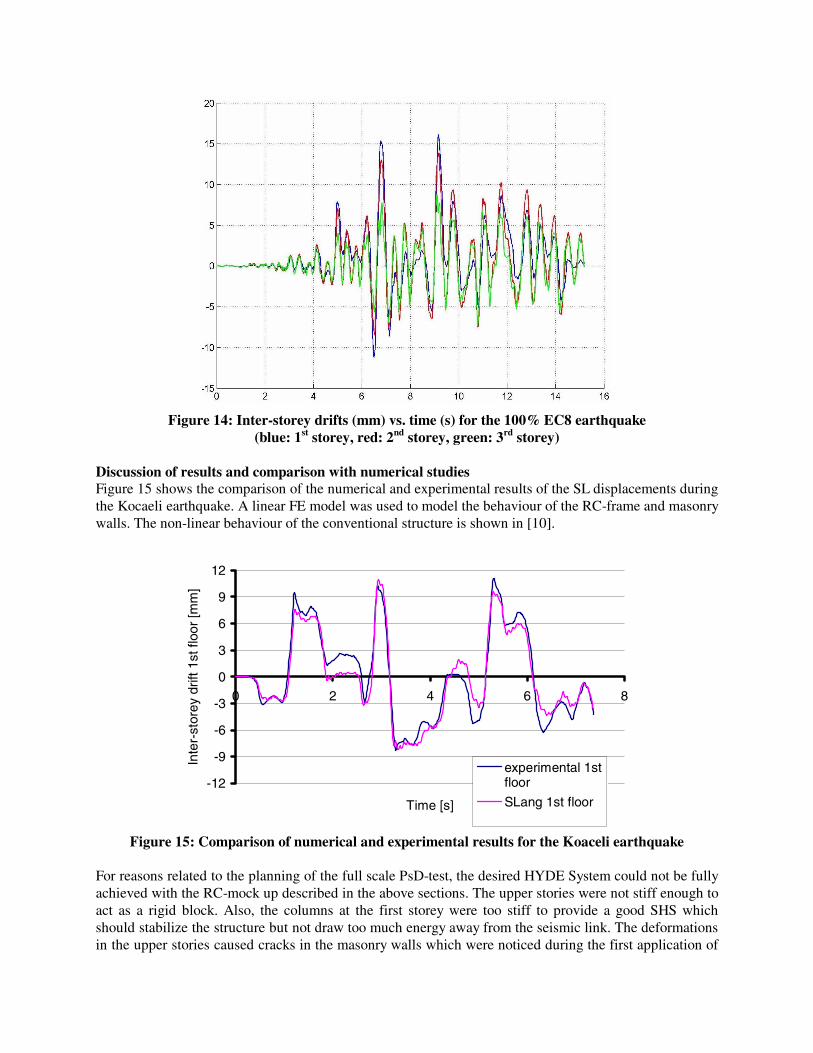
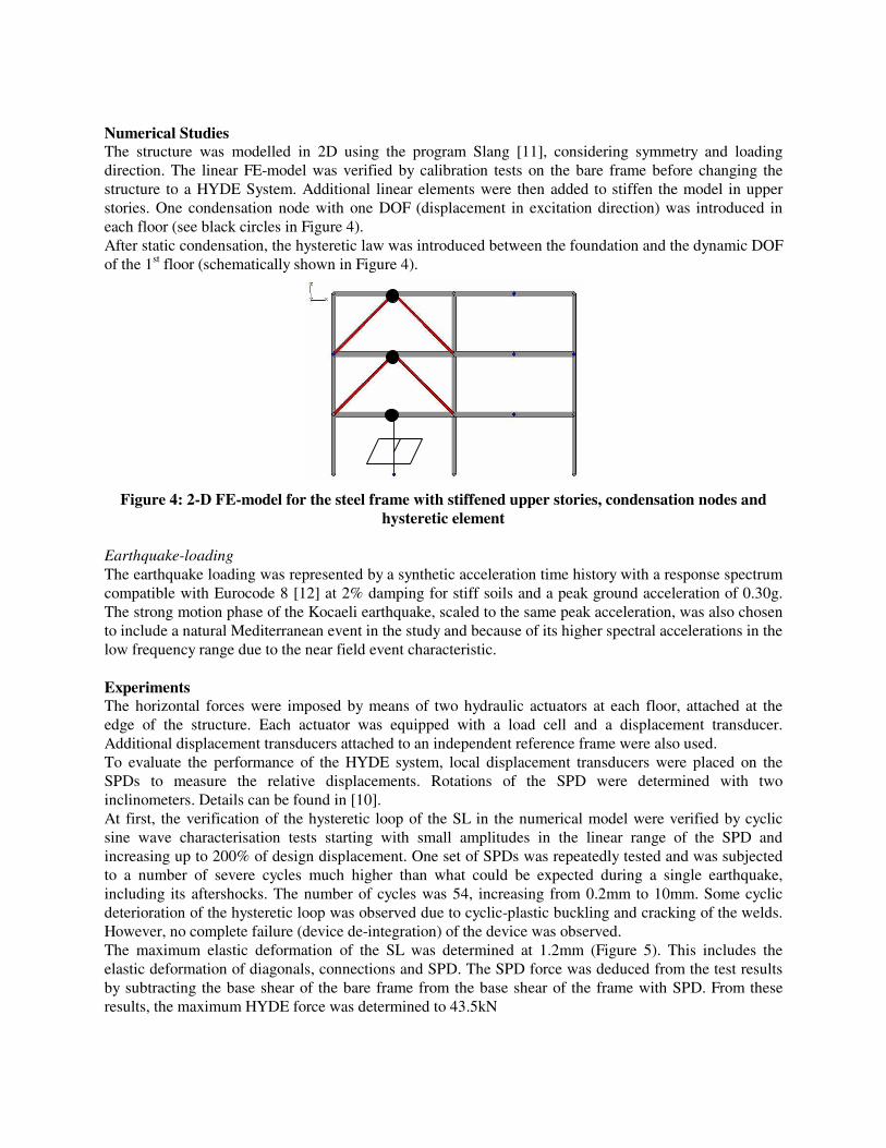
Figure 14: Inter-storey drifts (mm) vs. time (s) for the 100% EC8 earthquake
(blue: 1st storey, red: 2nd storey, green: 3rd storey) Discussion of results and comparison with numerical studies Figure 15 shows the comparison of the numerical and experimental results of the SL displacements during the Kocaeli earthquake. A linear FE model was used to model the behaviour of the RC-frame and masonry walls. The non-linear behaviour of the conventional structure is shown in [10].
-12
-9
-6
-3
0
3
6
9
12
0 2 4 6 8
Time [s]
Inte
r-st
orey
drif
t 1st
floo
r [m
m]
experimental 1stfloor
SLang 1st floor
Figure 15: Comparison of numerical and experimental results for the Koaceli earthquake
For reasons related to the planning of the full scale PsD-test, the desired HYDE System could not be fully achieved with the RC-mock up described in the above sections. The upper stories were not stiff enough to act as a rigid block. Also, the columns at the first storey were too stiff to provide a good SHS which should stabilize the structure but not draw too much energy away from the seismic link. The deformations in the upper stories caused cracks in the masonry walls which were noticed during the first application of
the design earthquake. Due to these cracks the linear behaviour of the conventional structure as assumed in the numerical model was not completely achieved in the tests. Even though, the numerical results are quite close to the test results showing that these non-linearities had a minor effect on the structure’s response (Figure 15). The nonlinear behaviour of the masonry in-fill cannot be considered with a statically condensed elastic model. But, for a true HYDE system this is not necessary, because the walls remain elastic. The friction devices showed stable stiff-ductile hysteretic loops. The pre-stressing force applying the normal force to the contact surface was adjusted with high precision disc springs. The variation of the pre-stressing forces in the bolts during the tests was small. Some cyclic variation was noticed for the centre devices [10]. This may be explained by local imperfections due to thickness variations and out-of-alignment of the concrete plate that provides the friction path. However, a moderate reduction in local concrete thickness due to creep or frictional wear will not influence the pre-stressing force considerably. The opposite is true for an increase in thickness due to manufacturing imperfections encountered along the friction path: the friction force will increase noticeably with cyclic loading in a cyclic fashion. Such a variation can be reduced by adjusting the displacements of the pre-stressing disc spring packages to the centre of their respective plateaus. During manufacturing of the concrete plates, the distance of the fixed connections of the friction plates to the edge of the concrete wall was reduced, leading to failure of the NW friction device during the final test. Although these are simple and inexpensive friction devices, the experiments highlighted the necessity for a controlled design, manufacturing and implementation process since “typical” design and manufacturing “variability” may negatively affect the proper functioning of these devices.
CONCLUSIONS AND FURTHER WORK The numerical model assumptions for HYDE Systems were verified by these one-half and full-scale tests: according to these, the conventional part of a HYDE System can be modelled with linear elements and a static condensation can be performed prior to the non-linear time history analysis. It is usually sufficient to place dynamic DOFs that participate in the movements of the structure in one node per floor, assuming the floors to be rigid diaphragms and harbouring the main masses. The non-linear behaviour of a seismic link can be described with an elasto-plastic hysteretic law for the storey shear vs. storey drift. For reasons of numerical stability, it may be based on a Bouc-Wen type model. This modelling approach is very efficient and leads to accurate estimates for the system’s important response quantities. The superior behaviour and efficiency of the HYDE System concept in comparison to other structural concepts has been presented already in many papers using this modelling approach. The superior behaviour of the HYDE System was demonstrated in the tests presented in this report, where a significant reduction of forces and displacements was achieved. For the steel frame retrofit, efficient steel bracing systems were chosen to provide the necessary stiffness in the upper floors. As HYDE, a shear panel device (SPD) made of mild steel was designed according to the displacement and force requirements of the project. The SPD showed a very predictable and stable behaviour up to a strain of 10%, equal to twice the design limit. The plastic buckling of the web and weld ruptures observed at the end of the test did not cause a complete failure of the device. This makes a shear panel a very accurate, robust, inexpensive and therefore ideal HYDE. Further investigations are necessary to provide adequate connections for SPDs. The RC frame with masonry in-fill in the upper stories was retrofitted using pre-fabricated concrete walls with friction devices in the Seismic Link at the ground floor. Because of limitations for PsD testing, the required stiffness in the upper floors could not be realized. The tests confirmed the modelling approach, even in the presence of smaller non-linearities due to cracking in the masonry walls.

The friction devices also performed very well with the special disc springs, providing an excellent way of controlling and maintaining the friction force. They require more effort and expertise on site to secure stable and long-term behaviour when compared to SPDs. On the other hand, friction devices need not be exchanged after an event and by simply releasing them after an earthquake, the structure moves back into its initial position by virtue of its SHS. When using prefabricated concrete walls as stiff supports for HYDEs in a Seismic Link, special attention must be paid to the connections to the existing structure and accuracy with respect to the HYDE connections. Typical prefab connections or dowel systems are often not certified for earthquake loads which then require further considerations.
REFERENCES 1. Dorka UE. “Hysteretic Device systems for earthquake protection of buildings” 5th U.S. National
Conference on Earthquake Engineering, 1994 Chicago, US 2. Dorka UE and Bayer V. “Distribution of Seismic Links in Hysteretic Device Systems” 12th World
Conference on Earthquake Engineering, 2000 Auckland, New Zealand 3. Schmidt K and Dorka UE. “Seismic Retrofitting of Residential Buildings with HYDE Systems” 3rd
World Conference on Structural Control, 2002 Como, Italy 4. Dorka UE and Conversano GA “Seismic retrofit of Allstate Building” IABSE symposium pp.145-
150, 1995 San Francisco, US 5. Magonette GE and Negro P. “Verification of the pseudodynamic test method” European Earthquake
Engineering 1998 6. Wen YK. “Equivalent linearization for hysteretic systems under random excitation” 1980 ASME
Journal of Applied Mechanics, Vol.47 No.1 pp.150-154 7. Dorka UE. “Erdbebensicherung durch HYDE-Systeme“ Festschrift Prof. Valtinat, University of
Hamburg-Harburg, 2001 Germany (in German) 8. Dorka UE and Schmidt K. “Retrofitting of Buildings with Masonry Infill using HYDE concept”
12th European Conference on Earthquake Engineering, 2002 London, UK 9. Taucer F, Negro P and Colombo A. “Low-cycle fatigue cyclic and PsD testing of two-storey
moment resisting steel frame with beam-to-column welded connections” Journal of Earthquake Engineering 2000 4(4), 437-477
10. Schmidt K, Dorka UE, Magonette GE and Taucer F. “Retrofitting of Steel Frame and RC Frame with HYDE Systems“ EUR Report 2004
11. SLang, the Structural Language “User’s Manual” Institut für Strukturmechanik, Bauhaus Universität Weimar (Hrsg.), 1998 Weimar, Germany
12. Eurocode8 “Design of structures for earthquake resistance” Part 1-1: General rules - seismic actions and general requirements for structures and Part 1-2: General rules - rules for buildings ENV 1998-1-1 and ENV 1998-1-2, 1994
13 Negro P and Mola E. “Current assessment Procedures: application to regular and irregular structures compared to experimental results” 3rd European Workshop on the Seismic Behaviour of Irregular and Complex Structures, 2002 Florence, Italy
14. Roik U and Dorka UE. “Fast online earthquake simulation of friction-damped systems” SFB 151-Berichte Nr.15, Sonderforschungsbereich Tragwerksdynamik Ruhr-Universität Bochum, 1989 Germany