Cloud Mask: Results, Frequency, Bit Mapping, and Validation UW Cloud Mask Working Group.

HAL Id: hal-02927466https://hal.archives-ouvertes.fr/hal-02927466
Submitted on 24 Sep 2020
HAL is a multi-disciplinary open accessarchive for the deposit and dissemination of sci-entific research documents, whether they are pub-lished or not. The documents may come fromteaching and research institutions in France orabroad, or from public or private research centers.
L’archive ouverte pluridisciplinaire HAL, estdestinée au dépôt et à la diffusion de documentsscientifiques de niveau recherche, publiés ou non,émanant des établissements d’enseignement et derecherche français ou étrangers, des laboratoirespublics ou privés.
Experimental Validation of a 2-Bit ReconfigurableUnit-Cell for Transmitarrays at Ka-Band
Antonio Clemente, Fatimata Diaby, Luca Di Palma, Laurent Dussopt, RonanSauleau
To cite this version:Antonio Clemente, Fatimata Diaby, Luca Di Palma, Laurent Dussopt, Ronan Sauleau. ExperimentalValidation of a 2-Bit Reconfigurable Unit-Cell for Transmitarrays at Ka-Band. IEEE Access, IEEE,2020, 8, pp.114991-114997. �10.1109/ACCESS.2020.3003698�. �hal-02927466�

Received June 10, 2020, accepted June 16, 2020, date of publication June 19, 2020, date of current version July 1, 2020.
Digital Object Identifier 10.1109/ACCESS.2020.3003698
Experimental Validation of a 2-Bit ReconfigurableUnit-Cell for Transmitarrays at Ka-BandANTONIO CLEMENTE 1,2, (Senior Member, IEEE),FATIMATA DIABY1,2, LUCA DI PALMA1,2, (Member, IEEE),LAURENT DUSSOPT 1,2, (Senior Member, IEEE),AND RONAN SAULEAU 3, (Fellow, IEEE)1Université Grenoble-Alpes, 38400 Grenoble, France2CEA-Leti, 38054 Grenoble, France3CNRS, Institut d’Électronique et de Télécommunications de Rennes (IETR), University of Rennes 1, 35000 Rennes, France
Corresponding author: Antonio Clemente ([email protected])
This work was supported by the National Research Agency through the project TRANSMIL under Grant ANR-14-CE28-0023.
ABSTRACT This paper presents the experimental results of a 2-bit electronically reconfigurable unit-cellfor transmitarrays at Ka-band. The proposed unit-cell architecture is based on a six-metal layers design andthree dielectric substrates. Two patch antennas are printed respectively on the top and bottom layers of thestack-up to achieve an antenna-filter-antenna structure. To implement the desired 2-bit phase resolution, twop-i-n diodes are bonded on each patch. The unit-cell has been fabricated and characterized in a specificwaveguide simulator. The measurement results are compared to the simulated ones and show minimumtransmission loss in the range 1.5 – 2.3 dB. The 3-dB fractional bandwidth is in the range 10.1 – 12.1%.
INDEX TERMS Transmitarray antennas, beam steering, beam forming, Ka-band, discrete lens,electronically steerable antenna.
I. INTRODUCTIONRelatively low cost and low power consumptionbeam-forming architectures are required to develop inno-vative electronically steerable antennas for the future massmarket high-data-rate satellite and terrestrial communica-tions. In this context, spatial feeding techniques combinedwith Printed Circuit Boards (PCB) technologies representcost-effective solutions to design innovative electronicallyreconfigurable antennas based on the reflectarray or transmi-tarray concepts [1]. On one side, for large antenna apertures,the spatial feeding mechanism drastically reduces the lossand complexity of the power division network compared toclassical phased array architectures. On the other side, PCBtechnologies are compatible with the integration on the arrayaperture of p-i-n diodes, RF-MEMS switches, varactors, etc.,which can be used to easily control the antenna aperturephase distribution without using complex and lossy phaseshifters. Furthermore, as they operate in transmission mode,transmitarrays are also compatible with solutions to reducethe overall antenna profile [2]–[4].
Several printed electronically steerable transmitarrayshave been demonstrated in the last decade from L- up
The associate editor coordinating the review of this manuscript and
approving it for publication was Guido Valerio .
to Ka-band [5]. Continuous phase control [6]–[8] orphase quantization techniques [9]–[16] are used totune the transmission phase and perform beam-formingfunctions.
This paper focuses on the experimental characterizationof a 2-bit unit-cell based on p-i-n diodes and operating atKa-band. Therefore, this unit-cell can be electronically recon-figured to provide four phase states mutually shifted by90◦. A 2-bit phase quantization significantly improves thetransmitarray performance in terms of collimating capability(e.g. improved directivity and lower slide lobe level) com-pared to the 1-bit architectures. At same time, such anapproach provides a very good trade-off between numberof solid-state components, complexity of the bias network,efficiency, bandwidth, and power consumption, compared tothe continuous phase shift based unit-cell designs. Indeed,a transmitarray with a 2-bit phase quantization exhibitsa typical aperture efficiency around 30-40% [15], [16],which is comparable to configurations with continuous phasecontrol [2].
To the best of the authors’ knowledge, excluding ourvery preliminary studies [17], only one 2-bit electronicallyreconfigurable unit-cell based on RF-MEMS switches hasbeen previously demonstrated [9]. However, such unit-cellhas been realized considering a wafer-based technology and
VOLUME 8, 2020 This work is licensed under a Creative Commons Attribution 4.0 License. For more information, see https://creativecommons.org/licenses/by/4.0/ 114991

A. Clemente et al.: Experimental Validation of a 2-Bit Reconfigurable Unit-Cell for Transmitarrays at Ka-Band
includes five switches biased with six independent bias lines.This solution is much more complex than the one pro-posed here where we use only four p-i-n diodes and twobias lines per unit-cell. Furthermore, the performance pre-sented in [9] are highly affected by the large value ofthe RF-MEMS switch resistance, with insertion loss in therange 4.9-9.2 dB (depending on the phase-shift state of theunit-cell). As clearly presented in the recent survey paper[5], phase quantization with 1-bit resolution is typically usedin the actual state-of-the-art on electronically reconfigurabletransmitarrays; this choice is often driven by the fact that 1-bitphase quantization can be achieved using a limited number ofswitches andmetal layers. The unit-cell architecture validatedexperimentally here paves the way for 2-bit steerable trans-mitarrays at Ka-band, with improved performance comparedto their 1-bit counterparts.
This paper is organized as follows. The fabricated 2-bitunit-cell and its experimental setup in waveguide are pre-sented in Section II. The measurement results are discussedin Section III. They are also compared to those achieved withfull-wave electromagnetic simulations. Moreover, the impactof the bias current is also discussed. Finally, conclusions aredrawn in Section IV.
II. 2-BIT RECONFIGURBALE UNIT-CELL: FABRICATIONAND EXPERIMENTAL SETUPA. FABRICATED UNIT-CELLThe proposed unit-cell (size of 5.1 × 5.1 × 1.3 mm3,λ0/2 × λ0/2 × λ0/8 at 29 GHz) has been recently usedto demonstrate an electronically reconfigurable transmi-tarray showing the possibility to steer the beam over a120 × 120-degree window [15], [16]. Nonetheless, its indi-vidual characterization has never been reported yet. Thisconstitutes the main objective of this contribution.
The proposed architecture is based on six-metal layer(M1 – M6 in Fig. 1(a), thickness 18 µm) stack-up withthree RT/Duroid 6002 Rogers substrates (εr = 2.94,tanδ = 0.0012) and two bonding films (RO4405F,εr = 3.52, tanδ = 0.004, thickness 100 µm). The substratebetween layers M5-M6 has a thickness of 508 µm. Instead,the substrates between layers M1-M2 and M3-M4 have athickness of 254 µm. The six metal layers are the following:transmitting (Tx) patch antenna (M1), delay line (M2), biasline associated to the Tx patch (M3), ground plane (M4), biasline associated to the receiving (Rx) patch (M5), and the Rxpatch (M6). Standard Printed Circuit Board (PCB) process,i.e. with minimum trace width of 80 µm and minimumvia-diameter of 120µm, has been selected to demonstrate thepossibility to implement the proposed design by using matureand relatively low cost fabrication technologies.
Two p-i-n diodes MACOM MA4AGP907, indicated asD1 – D4 in Fig. 1, are flip-chipped on each radiating ele-ment (O-slotted rectangular patch antennas, as representedin Fig. 1(b)) to control electronically the transmission phaseof the unit-cell with the required 2-bit phase resolution.Four phase states (UC000, UC090, UC180, and UC270)
FIGURE 1. Reconfigurable 2-bit unit-cell. (a) Three-dimensional view.(b) Schematic view of the experimental setup (waveguide simulator) andphotographs of the realized prototype: transmitting (Tx) patch printed onmetal layer M1, and receiving (Rx) patch printed on M6.
are generated by opportunely controlling the diode states aspresented In Table 1.
The two patch antennas having an O-slot are connected bya metallized via hole, with a diameter of 200 µm, to imple-ment an Antenna-Filter-Antenna unit-cell. For isolation rea-son, a 700-µm diameter hole is realized in the ground planeto allow the passage of this via. Metallized vias of diameter150 µm are realized between M1-M2, M3-M4, and M5-M6to correctly bias the p-i-n diodes and realize the 90◦ delay lineconnected on the Tx-patch.
From Table 1 it is clear that four switches (i.e. p-i-ndiodes in this specific design) is the minimum number ofdevices required to achieve a 2-bit phase quantization. Thenumber of diodes per unit-cell used in our design can becompared with ref. [9] where 5 RF-MEMS switches are usedto achieve the same phase resolution. Furthermore as bothdiodes of each pair of p-i-n diodes (i.e. D1-D2 and D3-D4)are biased in opposite state (see Fig. 2(a)), the proposedunit-cell contains only two bias lines, as compared to 6 linesrequired [9].
114992 VOLUME 8, 2020

A. Clemente et al.: Experimental Validation of a 2-Bit Reconfigurable Unit-Cell for Transmitarrays at Ka-Band
TABLE 1. P-i-n diodes bias state as a function of the unit-celltransmission phase state.
FIGURE 2. (a) Configuration of the p-i-n diodes mounted in the oppositedirection (series). Equivalent model of the diode p-i-n: (b) forward bias(ON), and (c) reverse bias (OFF).
The equivalent electrical model of the diodes(see Fig.s 2(b)-(c)) has been extracted up to 40GHz by fitting,in simulations, two-port on-probe measured S-parametersof the devices mounted on an ad-hoc board [18]. For aforward bias current Ibias equal to 10 mA, the equivalentmodel consists of a series L-R circuit (Ron = 4.2 � andLd = 0.05 nH). In the reverse state (Vbias = 1.2 V), the diodeis modelled as a shunt R-C circuit (Roff = 300 k� andCoff = 42 fF) with a series inductor (Ld = 0.05 nH). TheGallium-Arsenide packaging (εr = 12.9) of the p-i-n diodes,with dimensions of 0.686×0.368×0.19mm3, is also includedin the full-wave model of the unit-cell (see Fig. 1(a)). Moredetails on the unit-cell optimization, full-wave simulation
setup, geometrical parameters, and operation principle arepresented in our preliminary paper [17].
The unit-cell operation principle and p-i-n diode impactscan be analyzed by plotting the surface current distributionscomputed on the Tx and Rx patch antennas as a function of thediode states (Fig. 3). As presented in Fig. 3(a) and consideringthe configuration of Fig. 2(a), when the Tx patch is biasedwith a positive current D1 is ON, whereas D2 is in the OFFstate. By inverting the sign of the bias current (D1 OFFand D2 ON, Fig. 3(b)), the current flow is inverted and aphase-shift of 180◦ is achieved. Almost the same behavioris achieved on the Rx patch when the diodes D3 and D4 arecontrolled (Fig.s 3(c)-(d)). However, when the diodes D3 isON and D4 is OFF (Fig. 3(d)), the current flows on the delayline producing a 90◦ phase-shift.
B. ELECTROMAGNETIC SIMULATION ANDMEASUREMENT SETUPSThe unit-cell has been characterized using a waveguidesimulator based on standard WR28 waveguides(7.112 × 3.556 mm2), as presented in Fig. 1(b). It is com-posed by two coax-to-WR28 adaptors, two WR28 straightwaveguide sections, and two tapered transitions betweenthe rectangular section of the waveguide and the squareaperture of the unit-cell. The length of these transitions equals1.2 mm (λ/8.6); its value has been optimized to minimize theimpedance mismatch and the impact of oblique incidence inthe waveguide simulator [19].
Full-wave simulations using Ansys HFSS v2019 havebeen performed to study the impact of oblique incidenceon the scattering parameters of the unit-cell. For this pur-pose, three different configurations have been considered:unit-cell embedded in a WR28 standard rectangular waveg-uide (Fig. 1(b)), unit-cell with periodic boundary conditions
FIGURE 3. Surface current distributions of the unit-cell for the four phase states on the Tx and Rx patch antennas.(a) Tx patch when D1 is ON and D2 is OFF, (b) Tx patch when D1 is OFF and D2 is ON, (c) Rx patch when D3 is ONand D4 is OFF, and (d) Rx patch when D3 is OFF and D4 is ON.
VOLUME 8, 2020 114993
A. Clemente et al.: Experimental Validation of a 2-Bit Reconfigurable Unit-Cell for Transmitarrays at Ka-Band
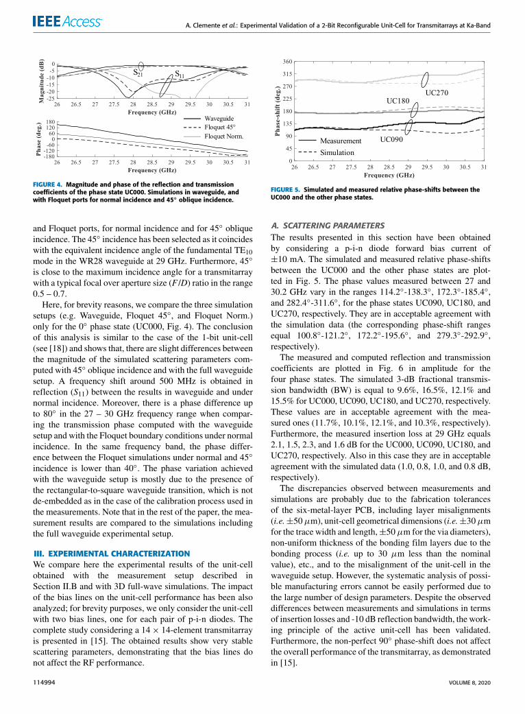
FIGURE 4. Magnitude and phase of the reflection and transmissioncoefficients of the phase state UC000. Simulations in waveguide, andwith Floquet ports for normal incidence and 45◦ oblique incidence.
and Floquet ports, for normal incidence and for 45◦ obliqueincidence. The 45◦ incidence has been selected as it coincideswith the equivalent incidence angle of the fundamental TE10mode in the WR28 waveguide at 29 GHz. Furthermore, 45◦
is close to the maximum incidence angle for a transmitarraywith a typical focal over aperture size (F /D) ratio in the range0.5 – 0.7.
Here, for brevity reasons, we compare the three simulationsetups (e.g. Waveguide, Floquet 45◦, and Floquet Norm.)only for the 0◦ phase state (UC000, Fig. 4). The conclusionof this analysis is similar to the case of the 1-bit unit-cell(see [18]) and shows that, there are slight differences betweenthe magnitude of the simulated scattering parameters com-puted with 45◦ oblique incidence and with the full waveguidesetup. A frequency shift around 500 MHz is obtained inreflection (S11) between the results in waveguide and undernormal incidence. Moreover, there is a phase difference upto 80◦ in the 27 – 30 GHz frequency range when compar-ing the transmission phase computed with the waveguidesetup and with the Floquet boundary conditions under normalincidence. In the same frequency band, the phase differ-ence between the Floquet simulations under normal and 45◦
incidence is lower than 40◦. The phase variation achievedwith the waveguide setup is mostly due to the presence ofthe rectangular-to-square waveguide transition, which is notde-embedded as in the case of the calibration process used inthe measurements. Note that in the rest of the paper, the mea-surement results are compared to the simulations includingthe full waveguide experimental setup.
III. EXPERIMENTAL CHARACTERIZATIONWe compare here the experimental results of the unit-cellobtained with the measurement setup described inSection II.B and with 3D full-wave simulations. The impactof the bias lines on the unit-cell performance has been alsoanalyzed; for brevity purposes, we only consider the unit-cellwith two bias lines, one for each pair of p-i-n diodes. Thecomplete study considering a 14× 14-element transmitarrayis presented in [15]. The obtained results show very stablescattering parameters, demonstrating that the bias lines donot affect the RF performance.
FIGURE 5. Simulated and measured relative phase-shifts between theUC000 and the other phase states.
A. SCATTERING PARAMETERSThe results presented in this section have been obtainedby considering a p-i-n diode forward bias current of±10 mA. The simulated and measured relative phase-shiftsbetween the UC000 and the other phase states are plot-ted in Fig. 5. The phase values measured between 27 and30.2 GHz vary in the ranges 114.2◦-138.3◦, 172.3◦-185.4◦,and 282.4◦-311.6◦, for the phase states UC090, UC180, andUC270, respectively. They are in acceptable agreement withthe simulation data (the corresponding phase-shift rangesequal 100.8◦-121.2◦, 172.2◦-195.6◦, and 279.3◦-292.9◦,respectively).
The measured and computed reflection and transmissioncoefficients are plotted in Fig. 6 in amplitude for thefour phase states. The simulated 3-dB fractional transmis-sion bandwidth (BW) is equal to 9.6%, 16.5%, 12.1% and15.5% for UC000, UC090, UC180, and UC270, respectively.These values are in acceptable agreement with the mea-sured ones (11.7%, 10.1%, 12.1%, and 10.3%, respectively).Furthermore, the measured insertion loss at 29 GHz equals2.1, 1.5, 2.3, and 1.6 dB for the UC000, UC090, UC180, andUC270, respectively. Also in this case they are in acceptableagreement with the simulated data (1.0, 0.8, 1.0, and 0.8 dB,respectively).
The discrepancies observed between measurements andsimulations are probably due to the fabrication tolerancesof the six-metal-layer PCB, including layer misalignments(i.e.±50µm), unit-cell geometrical dimensions (i.e.±30µmfor the trace width and length,±50µm for the via diameters),non-uniform thickness of the bonding film layers due to thebonding process (i.e. up to 30 µm less than the nominalvalue), etc., and to the misalignment of the unit-cell in thewaveguide setup. However, the systematic analysis of possi-ble manufacturing errors cannot be easily performed due tothe large number of design parameters. Despite the observeddifferences between measurements and simulations in termsof insertion losses and -10 dB reflection bandwidth, the work-ing principle of the active unit-cell has been validated.Furthermore, the non-perfect 90◦ phase-shift does not affectthe overall performance of the transmitarray, as demonstratedin [15].
114994 VOLUME 8, 2020

A. Clemente et al.: Experimental Validation of a 2-Bit Reconfigurable Unit-Cell for Transmitarrays at Ka-Band
FIGURE 6. Simulated and measured reflection and transmission coefficients of the unit-cell in the four phase states: (a) UC000, (b) UC090, (c) UC180,and (d) UC270. The measured results have been obtained using the waveguide setup described in Section II.B and the simulations have been carriedout using Ansys HFSS v2018.
FIGURE 7. Measured transmission coefficients in amplitude and phasefor UC000 as a function if the diode p-i-n bias current. Note that themeasured phase responses are superposed.
B. IMPACT OF BIAS CURRENTTo highlight the tradeoff between unit-cell power consumptionand insertion loss, the impact of the bias current on theunit-cell performance has also been investigated. Here,the bias current varies in the range 1-10 mA. The correspond-ing measured transmission coefficients of the UC000 areplotted in amplitude and phase in Fig. 7 for the bias currentvalues 1, 5, and 10 mA.
The measured minimum insertion losses are providedin Table 2 for the four phase states. Their value increasesby about 0.5 dB for a bias current of 1 mA (compared to10 mA) while the total power consumption is reduced by a
TABLE 2. Measured minimum insertion loss of the 2-bit unit-cell as afunction of the p-i-n diodes bias current.
TABLE 3. Measured transmission phase at 29 GHz of the 2-bit unit-cell asa function of the p-i-n diodes bias current.
factor 10. The measured increase of insertion loss at 29 GHzfor a bias current 1 mA (compared to 10 mA) is equal to0.33, 0.45, 0.35 and 0.39 dB for UC090, UC180, and UC270,respectively.
To complete the analysis, the measured transmission phaseat 29 GHz when the bias current varies in the range 1-10 mAis presented in Table 3. It is important to notice, that the
VOLUME 8, 2020 114995

A. Clemente et al.: Experimental Validation of a 2-Bit Reconfigurable Unit-Cell for Transmitarrays at Ka-Band
transmission phase response remains very stable on the fulloperation bandwidth as a function of the bias current value.
IV. CONCLUSIONA 2-bit electronically reconfigurable unit-cell for steerabletransmitarray has been optimized, fabricated, and fully char-acterized in a waveguide measurement setup. Four p-indiodes have been integrated on the two radiating elementsto control electronically the transmission phase with therequired 90◦ phase-shift difference.
The unit-cell frequency response has been also studiedexperimentally as a function of the p-i-n diode forward biascurrent (from 1 to10 mA). At 29 GHz the nominal transmis-sion insertion loss measured with a bias current of 10 mAis in the range 1.39-1.67 dB. The 3-dB transmission phasebandwidth varies between 10.1% and 12.1%. The experimen-tal results show an acceptable agreement when compared tofull-wave electromagnetic simulations.
REFERENCES[1] S. V. Hum and J. Perruisseau-Carrier, ‘‘Reconfigurable reflectarrays and
array lenses for dynamic antenna beam control: A review,’’ IEEE Trans.Antennas Propag., vol. 62, no. 1, pp. 183–198, Jan. 2014.
[2] J. G. Nicholls and S. V. Hum, ‘‘Full-space electronic beam-steering trans-mitarray with integrated leaky-wave feed,’’ IEEE Trans. Antennas Propag.,vol. 64, no. 8, pp. 3410–3422, Aug. 2016.
[3] A. Clemente, M. Smierzchalski, M. Huchard, C. Barbier, and T. L. Nadan,‘‘Characterization of a low-profile quad-feed based transmitarray antennaat V-band,’’ in Proc. 49th Eur. Microw. Conf. (EuMC), Paris, France,Oct. 2019, pp. 232–235.
[4] A. R. Vilenskiy, M. N. Makurin, and C. Lee, ‘‘Phase distribution optimiza-tion for 1-bit transmitarrays with near-field coupling feeding technique,’’ inProc. 14th Eur. Conf. Antennas Propag. (EuCAP), Copenhagen, Denmark,2020, pp. 1–5.
[5] J. R. Reis, R. F. S. Caldeirinha, A. Hammoudeh, and N. Copner, ‘‘Elec-tronically reconfigurable FSS-inspired transmitarray for 2-D beamsteer-ing,’’ IEEE Trans. Antennas Propag., vol. 65, no. 9, pp. 4880–4885,Sep. 2017.
[6] J. Y. Lau and S. V. Hum, ‘‘A wideband reconfigurable transmitarrayelement,’’ IEEE Trans. Antennas Propag., vol. 60, no. 3, pp. 1303–1311,Mar. 2012.
[7] J. R. Reis, M. Vala, and R. F. S. Caldeirinha, ‘‘Review paper on transmi-tarray antennas,’’ IEEE Access, vol. 7, pp. 94171–94188, 2019.
[8] M. Frank, F. Lurz, R. Weigel, and A. Koelpin, ‘‘Electronically reconfig-urable 6 × 6 element transmitarray at K-band based on unit cells withcontinuous phase range,’’ IEEE Antennas Wireless Propag. Lett., vol. 18,no. 4, pp. 796–800, Apr. 2019.
[9] C.-C. Cheng, B. Lakshminarayanan, and A. Abbaspour-Tamijani, ‘‘A pro-grammable lens-array antenna with monolithically integrated MEMSswitches,’’ IEEE Trans. Microw. Theory Techn., vol. 57, no. 8,pp. 1874–1884, Aug. 2009.
[10] W. Pan, C. Huang, X. Ma, B. Jiang, and X. Luo, ‘‘A dual linearly polar-ized transmitarray element with 1-bit phase resolution in X-band,’’ IEEEAntennas Wireless Propag. Lett., vol. 14, pp. 167–170, 2015.
[11] C. Huang, W. Pan, and X. Luo, ‘‘Low-loss circularly polarized transmitar-ray for beam steering application,’’ IEEE Trans. Antennas Propag., vol. 64,no. 10, pp. 4471–4476, Oct. 2016.
[12] M. Wang, S. Xu, F. Yang, and M. Li, ‘‘Design and measurement of a 1-bitreconfigurable transmitarray with subwavelength H-shaped coupling slotelements,’’ IEEE Trans. Antennas Propag., vol. 67, no. 5, pp. 3500–3504,May 2019.
[13] B. D. Nguyen and C. Pichot, ‘‘Unit-cell loaded with PIN diodes for 1-bitlinearly polarized reconfigurable transmitarrays,’’ IEEE Antennas WirelessPropag. Lett., vol. 18, no. 1, pp. 98–102, Jan. 2019.
[14] L. Di Palma, A. Clemente, L. Dussopt, R. Sauleau, P. Potier, andP. Pouliguen, ‘‘Circularly-polarized reconfigurable transmitarray in Ka-band with beam scanning and polarization switching capabilities,’’ IEEETrans. Antennas Propag., vol. 65, no. 2, pp. 529–540, Feb. 2017.
[15] F. Diaby, A. Clemente, R. Sauleau, K. T. Pham, and L. Dussopt, ‘‘2 bitreconfigurable unit-cell and electronically steerable transmitarray at Ka-band,’’ IEEE Trans. Antennas Propag., vol. 68, no. 6, pp. 5003–5008,Jun. 2020.
[16] A. Clemente, L. Di Palma, F. Diaby, L. Dussopt, K. Pham, and R. Sauleau,‘‘Electronically-steerable transmitarray antennas for Ka-band,’’ in Proc.13th Eur. Conf. Antennas Propag. (EuCAP), Krakow, Poland, 2019,pp. 1–4.
[17] F. Diaby, A. Clemente, L. Di Palma, L. Dussopt, K. Pham, E. Fourn, andR. Sauleau, ‘‘Design of a 2-bit unit-cell for electronically reconfigurabletransmitarrays at Ka-band,’’ in Proc. 47th Eur. Radar Conf. (EURAD),Nuremberg, Germany, Oct. 2017, pp. 1321–1324.
[18] L. Di Palma, A. Clemente, L. Dussopt, R. Sauleau, P. Potier, andP. Pouliguen, ‘‘1-bit reconfigurable unit cell for Ka-band transmitarrays,’’IEEE Antennas Wireless Propag. Lett., vol. 15, pp. 560–563, 2016.
[19] P. W. Hannan and M. A. Balfour, ‘‘Simulation of a phased-array antennain waveguide,’’ IEEE Trans. Antennas Propag., vol. AP-13, no. 3,pp. 342–353, May 1965.
ANTONIO CLEMENTE (Senior Member, IEEE)received the B.S. and M.S. degrees in telecommu-nication engineering and remote sensing systemsfrom the University of Siena, Italy, in 2006 and2009, respectively, and the Ph.D. degree in sig-nal processing and telecommunications from theUniversity of Rennes 1, France, in 2012.
FromOctober 2008 toMay 2009, he realized hismaster thesis project at the Technical Universityof Denmark (DTU), Lyngby, Denmark, where he
worked on spherical nearfield antenna measurements. His Ph.D. has beenrealized at CEA-Leti, Grenoble, France. In 2012, he joined the Researchand Development Laboratory of Satimo Industries, Villebon-sur-Yvette,France. Since 2013, he has been a Research Engineer with CEA-Leti. Hehas authored or coauthored more than 100 articles in international journalsand conferences, and received 12 patents. From 2016 to 2018, he has beenthe Technical Coordinator of the H2020 joint Europe and South Korea5GCHAMPION project. He serves as a reviewer for the numerous IEEEand IET journals in the field of Microwave, Antennas and Propagation.His current research interests include fixed-beam and electronically recon-figurable transmitarray antennas, millimeter-wave and sub-THz antennas,antenna arrays, near-field focused systems, antenna modelling, miniatureintegrated antennas, antenna fundamental limitations, and near-field andfar-field antenna measurements.
Dr. Clemente received the Young Scientist Award (First Prize) duringthe 15th International Symposium of Antenna Technology and AppliedElectromagnetics (ANTEM 2012) and the Best Antenna Design and Appli-cations Paper Award during the 13th European Conference on Antennas andPropagation (EuCAP 2109). He was a co-recipient of the Best Paper Awardat JNM 2015 (19emes Journées Nationales Microondes) and the 2019 ETRIJournal Best Paper Award.
FATIMATA DIABY received the B.S. degreein physics from the University Joseph Fourier,Grenoble, France, in 2011, and the M.S. degreein microelectronics and telecommunication engi-neering from Polytech Marseille, France, in 2014.She is currently pursuing the Ph.D. degree with theLaboratory of Antenna Propagation and InductiveCoupling (LAPCI), CEA-Leti, Grenoble.
Her research interests include electronicallyreconfigurable transmitarray antennas and the
development of numerical tools dedicated to the modeling and optimizationof transmit arrays.
Dr. Diaby was a co-recipient of the Best Antenna Design and ApplicationsPaper Award during the 13th European Conference on Antennas andPropagation (EuCAP 2109).
114996 VOLUME 8, 2020

A. Clemente et al.: Experimental Validation of a 2-Bit Reconfigurable Unit-Cell for Transmitarrays at Ka-Band
LUCA DI PALMA (Member, IEEE) was born inRome, Italy, in 1987. He received the B.Sc. degree(summa cum laude) in electronics and the M.Sc.degree (summa cum laude) in telecommunicationengineering from the University of Roma Tre,Rome, in 2009 and 2011, respectively, and thePh.D. degree in signal processing and telecommu-nications from the University of Rennes 1, Rennes,France, in 2015.
From 2013 to 2015, he worked as a ResearchAssistant with CEA-Leti, Grenoble, France. Since 2016, he has been aMicrowave and Antenna Engineer with Airbus Defence and Space inItaly. He has contributed to more than 40 articles and communicationsin revues and national and international conferences on antennas andmicrowave circuits. He serves as a Reviewer for the IEEE TRANSACTIONS ON
ANTENNAS AND PROPAGATION, the IEEE ANTENNAS AND WIRELESS PROPAGATION
LETTER, and IEEE ACCESS journals. His M.Sc. thesis project on metama-terials was awarded at the Marconi Junior Prize (Second Place), in 2012,Pontecchio Marconi, Italy. His research interests include metamaterials,wide-coverage antennas, phased arrays, reflector design, quasi-optic recon-figurable antennas, and planar and waveguide components at microwave andmillimeter-wave frequencies with focus on satellite applications.
Dr. Di Palma received the Best Paper Award from the French NationalConference onMicrowaves (JNM2015), Bordeaux, France, in June 2015. Hewas a co-recipient of the Best Antenna Design Paper Award at the EuropeanConference on Antennas and Propagation (EuCAP 2019), Krakow, Poland,in April 2019.
LAURENT DUSSOPT (Senior Member, IEEE)received the M.S. degree in electrical engineeringfrom the Ecole Normale Supérieure de Cachan,France, the Ph.D. degree in electrical engineer-ing from the University of Nice-Sophia Antipolis,France, in 2000, and the Habilitation à Dirigerdes Recherches degree from University JosephFourier, Grenoble, France, in 2008.
He was a Research Fellow with the Universityof Michigan, Ann Arbor, from 2000 and 2002,
where he developed reconfigurable microwave circuits and antennas basedon RF-MEMS technology. Since 2003, he has been with CEA-Leti, France,as a Research Engineer and a Project Leader on advanced antenna systemsfor wireless communications at microwave andmillimeter-wave frequencies.From 2013 to 2016, he has been a Chief Scientist of the Systems Division,CEA-Leti. Since 2016, he has been working on THz imaging systems withthe Optics and Photonics Division, CEA-Leti. He is currently a ResearchDirector of CEA-Leti. He has published more than 180 scientific articlesin international journals and conferences, eight book chapters, and severalpatents; he has contributes to the technical program committees of sev-eral international conferences and the IEEE MTT-20 Technical Committeeon wireless communications and organized several workshops in this field.
Dr. Dussopt received the Lavoisier Postdoctoral Fellowship from FrenchGovernment, in 2000. He was a co-recipient of conference prizes at the IEEERFIC’2002, ANTEM’2012, JNM’2015, and EuCAP’2019.
RONAN SAULEAU (Fellow, IEEE) received thedegree in electrical engineering and radio commu-nications from the Institut National des SciencesAppliquées, Rennes, France, in 1995, the Agréga-tion degree from the Ecole Normale Supérieure deCachan, France, in 1996, and the Ph.D. degree insignal processing and telecommunications and theHabilitation à Diriger des Recherches degree fromthe University of Rennes 1, France, in 1999 and2005, respectively.
He was an Assistant Professor and an Associate Professor with theUniversity of Rennes 1, from September 2000 to November 2005, and fromDecember 2005 to October 2009, respectively. He has been appointed as aFull Professor with the University of Rennes 1, since November 2009. He hasbeen the Co-Director of the research Department Antenna and MicrowaveDevices, IETR, and the Deputy Director of IETR, until 2016. He is currentlythe Director of IETR. He has been involved in more than 45 researchprojects at the national and European levels and has co-supervised 20 post-doctoral fellows, 45 Ph.D. students, and 50 master students. He received20 patents and is the author or coauthor of more than 220 journal articlesand 480 publications in international conferences and workshops. He hasshared the responsibility of the research activities on antennas at IETRin 2010 and 2011. His current research interests include numerical modeling(mainly FDTD),millimeter-wave printed and reconfigurable (MEMS) anten-nas, substrate integrated waveguide antennas, lens-based focusing devices,periodic and non-periodic structures (electromagnetic bandgap materials,metamaterials, reflectarrays, and transmitarrays), and biological effects ofmillimeter waves.
Prof. Sauleau has also been a member of the board of directors of EurAAP,since 2013. He received the 2004 ISAP Conference Young ResearcherScientist Fellowship, Japan, and the first Young Researcher Prize in Brit-tany, France, in 2001, for his research work on gain-enhanced Fabry-Perotantennas. In September 2007, he was elevated to junior member of theInstitut Universitaire de France. He was awarded the Bronze medal byCNRS, in 2008. He was a co-recipient of several international confer-ence awards with some of his students (International School of BioEM2005, BEMS’2006, MRRS’2008, E-MRS’2011, BEMS’2011, IMS’2012,Antem’2012, BioEM’2015, ESA Workshop’2018, and EuCAP’2019). Hehas served as a Guest Editor for the IEEE ANTENNAS PROPAGATION specialissue on Antennas and Propagation at mm and sub mmwaves. He has servedas a national delegate for COST VISTA. He has been national delegate forEurAAP, from 2013 to 2018.
VOLUME 8, 2020 114997


![VLIWBASED RUNTIME RECONFIGURABLE MACHINEVISION … · ASAP 2019 Metric Chen[2] Sun[3] Xiao[5] Ramirez-Martinez[6] Reichenbach[7] Proposed Precision 8 bit 16 bit 32 bit 32 bit 16 bit](https://static.fdocuments.in/doc/165x107/5f7785ac3bc4b131f04f0a8c/vliwbased-runtime-reconfigurable-machinevision-asap-2019-metric-chen2-sun3-xiao5.jpg)