Experimental Study on Structural Performance of RC...
12
Research Article Experimental Study on Structural Performance of RC Exterior Beam-Column Joints Retrofitted by Steel Jacketing and Haunch Element under Cyclic Loading Simulating Earthquake Excitation Cong-Thuat Dang and Ngoc-Hieu Dinh e University of Danang: University of Science and Technology, Da Nang, Vietnam Correspondence should be addressed to Cong-uat Dang; [email protected] Received 7 February 2017; Accepted 11 May 2017; Published 7 June 2017 Academic Editor: Christophe Petit Copyright © 2017 Cong-uat Dang and Ngoc-Hieu Dinh. is is an open access article distributed under the Creative Commons Attribution License, which permits unrestricted use, distribution, and reproduction in any medium, provided the original work is properly cited. Several retrofitting methods for reinforced concrete (RC) beam-column joints in old buildings without seismic details were developed. Four half-scale RC exterior beam-column joints were fabricated and tested under cyclic loading simulating earthquake excitation. e control specimen was designed to fail in joint shear. Two practical retrofitting strategies were applied to the control specimen which consider the architectural characteristic in real buildings, including steel jacketing and haunch retrofit solution. e structural performance of the test specimens was investigated in terms of various factors including damage and failure, load- driſt relationship, ductility, dissipated energy, and strain profiles of longitudinal reinforcement. Experimental results confirmed that the proposed retrofit methods were shown to enhance the seismic capacity of the joints in terms of the strength, deformation capacity, and energy dissipation capacity while the shear deformation in the panel zone significantly reduced in comparison with the control specimen. 1. Introduction Existing reinforced concrete (RC) buildings in many develop- ing countries had been traditionally designed to resist mainly gravity loads and wind loads without properly considering the seismic effects that pose a significant risk to human beings. In those buildings, beam-column joints have non- seismic reinforcement details. According to a previous report [1], the beam-column joints without seismic reinforcement details have been found to be susceptible to failure due to earthquakes which could contribute to partial or entire collapse of concrete buildings. erefore, to ensure the safety of the existing RC buildings, it is essential to improve the strength and ductility of beam-column joints. From the observations of structural failure due to earthquakes, corner and exterior concrete beam-column joints have been recog- nized as the most vulnerable parts of RC frames due to the discontinuity in beam, weak concrete confinement inside the joint, and unreliable load-transferring mechanism dependent on concrete tensile strength [1]. According to the previous studies by Lee et al. [2] and Teraoka et al. [3], the failure modes of nonseismically beam- column joints could be classified into three groups: B-failure ( / > 1.8) indicates flexural yielding of beams undergoing large inelastic deformation until ultimate rotational capacity without shear failure in joints; BJ-failure indicates joint failure aſter initial yielding of beam reinforcement (1≤ / ≤ 1.8); and J series indicate joint failure by shear force without yielding of beam reinforcement ( / ≤1), where / is the ratio of joint shear capacity to joint shear demand evaluated based on the beam yield and hardening mecha- nism. For the RC beam-column joints without seismic rein- forcement details, several repair and retrofitting methods have been proposed in recent years. Engindeniz et al. [4] grouped several repairing and strengthening techniques as follows: (i) epoxy repair; (ii) removal and replacement of con- crete in damaged areas; (iii) concrete jacketing; (iv) concrete masonry unit jacketing; (v) steel jacketing and addition of Hindawi Advances in Civil Engineering Volume 2017, Article ID 9263460, 11 pages https://doi.org/10.1155/2017/9263460
-
Upload
trinhtuong -
Category
Documents
-
view
220 -
download
3
Transcript of Experimental Study on Structural Performance of RC...

Research ArticleExperimental Study on Structural Performance of RC ExteriorBeam-Column Joints Retrofitted by Steel Jacketing and HaunchElement under Cyclic Loading Simulating Earthquake Excitation
Cong-Thuat Dang and Ngoc-Hieu Dinh
The University of Danang University of Science and Technology Da Nang Vietnam
Correspondence should be addressed to Cong-Thuat Dang dangcongthuatdutudnvn
Received 7 February 2017 Accepted 11 May 2017 Published 7 June 2017
Academic Editor Christophe Petit
Copyright copy 2017 Cong-Thuat Dang and Ngoc-Hieu DinhThis is an open access article distributed under the Creative CommonsAttribution License which permits unrestricted use distribution and reproduction in any medium provided the original work isproperly cited
Several retrofitting methods for reinforced concrete (RC) beam-column joints in old buildings without seismic details weredeveloped Four half-scale RC exterior beam-column joints were fabricated and tested under cyclic loading simulating earthquakeexcitation The control specimen was designed to fail in joint shear Two practical retrofitting strategies were applied to the controlspecimen which consider the architectural characteristic in real buildings including steel jacketing and haunch retrofit solutionThe structural performance of the test specimens was investigated in terms of various factors including damage and failure load-drift relationship ductility dissipated energy and strain profiles of longitudinal reinforcement Experimental results confirmedthat the proposed retrofit methods were shown to enhance the seismic capacity of the joints in terms of the strength deformationcapacity and energy dissipation capacity while the shear deformation in the panel zone significantly reduced in comparison withthe control specimen
1 Introduction
Existing reinforced concrete (RC) buildings inmany develop-ing countries had been traditionally designed to resist mainlygravity loads and wind loads without properly consideringthe seismic effects that pose a significant risk to humanbeings In those buildings beam-column joints have non-seismic reinforcement details According to a previous report[1] the beam-column joints without seismic reinforcementdetails have been found to be susceptible to failure dueto earthquakes which could contribute to partial or entirecollapse of concrete buildings Therefore to ensure the safetyof the existing RC buildings it is essential to improve thestrength and ductility of beam-column joints From theobservations of structural failure due to earthquakes cornerand exterior concrete beam-column joints have been recog-nized as the most vulnerable parts of RC frames due to thediscontinuity in beam weak concrete confinement inside thejoint and unreliable load-transferringmechanismdependenton concrete tensile strength [1]
According to the previous studies by Lee et al [2] andTeraoka et al [3] the failure modes of nonseismically beam-column joints could be classified into three groups B-failure(119881119899119881119906 gt 18) indicates flexural yielding of beams undergoinglarge inelastic deformation until ultimate rotational capacitywithout shear failure in joints BJ-failure indicates joint failureafter initial yielding of beam reinforcement (1 le 119881119899119881119906 le18) and J series indicate joint failure by shear force withoutyielding of beam reinforcement (119881119899119881119906 le 1) where 119881119899119881119906is the ratio of joint shear capacity to joint shear demandevaluated based on the beam yield and hardening mecha-nism
For the RC beam-column joints without seismic rein-forcement details several repair and retrofitting methodshave been proposed in recent years Engindeniz et al [4]grouped several repairing and strengthening techniques asfollows (i) epoxy repair (ii) removal and replacement of con-crete in damaged areas (iii) concrete jacketing (iv) concretemasonry unit jacketing (v) steel jacketing and addition of
HindawiAdvances in Civil EngineeringVolume 2017 Article ID 9263460 11 pageshttpsdoiorg10115520179263460
2 Advances in Civil Engineering
external steel elements and (vi) strengthening with fiber-reinforced polymeric (FRP) composite application
Shafaei et al [6] investigated the performance of fournonseismically detailed beam-column joints retrofitted withsteel angles which were mounted using prestressed cross-ties This technique prevented the slippage by increasing thejoint area of the bottom longitudinal reinforcement of beammoreover the plastic hingewas relocated far from the columnface and the shear strength stiffness energy dissipated andductility capacity were significantly increased up to 50120 220 and 220 respectively
In addition El-Amoury and Ghobarah [7] performedthe seismic tests on beam-column joints strengthened withglass fiber-reinforced polymers (GFRP) The retrofit strategyincluded two systems the first system is used for upgradingthe shear strength of the joint with two U-shaped GFRPlayers and the second system is used for upgrading the bond-slip of the steel bars The test results showed that the useof GFRP jacketing significantly enhanced the ductility andthe load-carrying capacity of the retrofitted beam-columnjoints Besides the brittle joint shear failure of the retrofittedspecimens was also eliminated and the stiffness degradationof the joints was reduced Particularly the energy dissipationcapacity was increased by up to six times compared to that ofnonretrofitted joints
Moreover the haunch retrofit solution (HRS) usinghaunch elements was proposed by Pampanin et al [8] andseveral comprehensive tests were performed by Genesio [9]using postinstalled anchors for optimization of the HRSThe main principle of HRS was to relocate the plastic hingeaway from the vulnerable panel zone thus enhancing theglobal response of RC beam-column joints without seismicreinforcement details by altering the hierarchy of strengthsuitably These tests had proved the efficiency of the HRS tothe hierarchy of strength in beam-column joints in order toprevent brittle joint shear failure and induce the ductile beamfailure at much higher lateral loads
In this study to develop the seismic retrofitting tech-niques to beam-column joints in existing concrete buildingsin Korea four half-scale RC exterior beam-column jointswere tested A control specimen is designed to be failed inJ-failure which refers to joint failure before plastic hingesformed at the ends of adjacent beams Thus this specimen isassociatedwith low displacement and ductilityThen two dif-ferent retrofit strategies were applied to the control specimensteel jacketing and haunches retrofit solutionThe retrofittingmethods used in this study emphasize the practical detailsarchitectural characteristics of real buildings and construc-tion ability of retrofittingmethods All specimens were testedunder simulated seismic loading Based on the test results thestructural performance of control and retrofitted specimens isassessed in terms of various factors failure mode hystereticbehavior drift capacity and energy dissipation capacity
2 Experimental Program
21 Test Specimens Figure 1 shows a typical RC 10-storybuilding in Korea with 3900mm in story height and three
4500
3960
0
Prototype
3 times 8000 = 24000
9times39
00=
3510
0
Figure 1 A typical RC 10-story building
bays of 8000mm This building was built with a nonseis-mic reinforcement details which is generally designed andconstructed in Korea during 1970s and 1980s As reportedby Korea National Emergency Management Agency [10]the beam-column joints of old buildings constructed during1970s and 1980s in Korea do not have seismic reinforcementdetails stirrups or ties had standard 90-degree hooks andlarge spacing and the anchorage of top longitudinal rein-forcing bars of beams was bent down inside the joint regionswhile the anchorage of bottom longitudinal reinforcing barswas bent down away from joint regionswhichmight decreasestrength and deformation capacity of the joints [10] Allspecimens in this studywere designed to simulate the exteriorbeam-column joints in secondfloor of the buildingwith a halfscale
The control specimen (specimen J) has nonseismic rein-forcement details inside the joint region In this study toachieve J-failure mode of the control specimen the designtop reinforcement ratio of beams was 29 corresponding toa ratio of joint shear capacity to joint shear demand 119881119899119881119906of 073 For all specimens for positive bending momentof beams the bottom longitudinal reinforcement ratios ofbeams had the same value of 043 The configurations anddetails of specimen J were presented in Figure 2
Figure 3 illustrates the schematic drawings of retrofittedspecimens It should be noted that in test specimens only aportion of the joint panel zones was retrofitted with retrofitmaterials to consider the existence of transverse beams andfloor slabs in real structures However the effect of transversebeam and slab confinement on seismic performance ofexterior RC beam-column joints is not clarified so far [1112] Moreover in this study the authors consider the worst
Advances in Civil Engineering 3
D10150 D1050
300 2100
D10
15
0D
10
50 250
850
300
850
250
2500
D10
50
A A
BB
300
300 6-D25
D10
Section A-A
300
200
3-D10
2-D19D10
3 -D22
Section B-B
Figure 2 Configurations and details of control specimen
Steel jacketing in joint Photo of J-S1
A-A
Beam
Column
100Transverse
beam
Slab
Anchor bolts
A
A
1100
Epoxy grout (5 mm)
Steel plates (16 mm)
(a) Specimen J-S1
B-B
100 Transverse beam
B
B
510
Slab
Anchor bolts
Column
Beam
Steel jacketing in joint Photo of J-S2
Epoxy grout (5 mm)
Steel plates (16 mm)
(b) Specimen J-S2
205
Transverse beam
Slab
440424
C
C
Anchor bolts
Beam
Column
Haunch element detailsPhoto of J-H
Steel plates (16 mm)
(c) Specimen J-H
Figure 3 Details of retrofitted specimens
4 Advances in Civil Engineering
Table 1 Test results of concrete compressive strength
Specimens J J-S1 J-S2 J-HTesting day (days) 20 21 23 25Concrete compressivestrength 1198911015840119888 (MPa) 2087 2014 1864 198
circumstance of joints subjected to lateral load without con-finement in joint region for rehabilitation purpose Hence inthis study the concrete transverse beams and slabs were notincluded in test specimens
Figures 3(a) and 3(b) show the details of specimens J-S1and J-S2 which were strengthened in joints with steel jackets(SS400) having a thickness of 16mm and specified yieldstrength of 400MPa In specimen J-S1 (Figure 3(a)) two sidesof column were attached with steel plates having a length of1100mm which were installed with anchor bolts HILTI HSL-3M12 (the diameter of 12mm and the length of 120mm)Meanwhile in specimen J-S2 three sides of column wereinstalled with steel plates with bolts as shown in Figure 3(b)It is noted that the surfaces of concrete were covered by a layerof epoxy grout having a thickness of 5mm before steel plateswere installedThe details of steel jacket design procedure aresummarized in Appendix A
Figure 3(c) shows the details of specimen J-H which wasstrengthened using haunch retrofit solution In this retrofittedtechnique a haunch element was only installed at the bot-tom part of the beam due to considering the architecturalcharacteristic in real buildings The haunch element usedin this test consisted of three steel plates welded togetherThe design length of haunch element is 424mm which is02 times the length of the beam (2100mm) according tothe recommendation by Sharma et al [13] To connect thehaunch element with beam and column five anchor boltsHILTI HSL-3M12 (the diameter of 12mm and the length of120mm) at each side of beam and column were used Thedetails of haunch element design procedure are summarizedin Appendix B
22 Materials To consider the low strength of concrete andsteel rebars used in the existing concrete frame buildingsbased on a Korea investigation report all specimens wereconstructed with normal-weight concrete having the designcompressive strength of 21MPa Table 1 showed the averagecompressive strength of three standard cylindrical specimensfor each concrete batch based on the uniaxial compressivetests on the loading day according to KS F 2405 [14]
As for longitudinal and transverse reinforcement grade300 (specified yield strength = 300MPa) was used The steelreinforcing bars of D10 D16 D19 and D22 have diameters of10 16 19 and 22mm respectively Uniaxial tension tests wereperformed according to KS B 0802 [15] and 0814 [16] and theactual average yield strengths and ultimate strengths acquiredwere listed in Table 2
23 Test Setup and Measuring Instruments Test setup aimedto reproduce the deformed shape and internal forces in beam-column joints subjected to cyclic lateral loading Figure 4
Table 2 Test results of reinforcing bars
Reinforcing bars Yield tensilestrength 119891119910 (MPa)
Ultimate tensilestrength 119891119906 (MPa)
D10 405 587D16 363 549D19 372 555D22 383 584
illustrates a photo of the test setup In the figure the columnofthe join is placed in a vertical position and the beam is placedin a horizontal position The top and the bottom ends of thecolumns are connected to hydraulic actuator and strong floorrespectively Moreover lateral cyclic loading is applied to thetop of the columns by a 500 kN hydraulic actuator in order tosimulate earthquake loadingThepin connection at the end ofa beam is supported by an axial steel link connected at its baseA lateral support system is connected to a reaction frame toprevent out-of-plane movement of test specimens
The lateral loading is applied to specimens at the tipof columns to simulate earthquake loading by a 500 kNhydraulic actuator The cyclic loading history is shown inFigure 5 according to the specification of ACI 3742R-13 [17]with two cycles at each drift ratio level of 025 05 0751 2 3 4 5 and so on until failure In this study noaxial force was applied on the top of columns [18] Howeverfurther investigation on the effect of the column compressionforce on the behavior of beam-column joints is necessary
Figures 6 and 7 present the location of linear variable dis-placement transducers (LVDTs) and strain gauges attachedto specimens respectively A LVDT was placed at the upperend of the column to measure the total lateral displacementMoreover shear deformation of panel zones wasmeasured bya set of LVDTs as shown in Figure 6
For each specimen a total of 14 electrical resistancestrain gauges were attached to longitudinal and transversereinforcement of a beam and two columns around a panelzone to measure the magnitude of reinforcing bars strainsdeveloped during different loading stages As shown in Fig-ure 7 the column reinforcing bars were gauged at the locationnext above the connection part (strain gauges number 1 andnumber 2) The beam reinforcing bars were gauged at twodifferent locations one is adjacent to the joint part (straingauges numbers 3 4 5 and 6) and the other is inside thejoints (strain gauges numbers 7 8 9 10 11 and 12) to checkthe yield penetration of beam reinforcement The transversereinforcement of columns and beams was gauged to monitorthe strains (strain gauges number 13 and number 14) Boththe displacement and strain data were collected using the dataacquisition system
3 Test Result Analysis and Discussions
31 Hysteretic Behavior Figure 8 shows the relationshipbetween the applied lateral load and drift ratio of test spec-imens which is the ratio between the lateral displacement
Advances in Civil Engineering 5
Lateral supportLateral actuator
Strong floor
Hinge
LVDT
Col
umn
Reac
tion
fram
e
2250
1000
1000 Rigid
link
Hinge
250
2100
Unit mm
Beam
(500 kN)
minus (Pull) + (Push)
(a) Diagram
Actuator
Specimen
Lateral support
Rigid linkHinge
Hinge
Reaction frame
Actuator
Specimen
Lateral support
Rigid linkHinge
Hinge
Reaction frame
(b) Photograph of test setup
Figure 4 Test setup of specimens
025 05 075 12
34
5
minus6
minus4
minus2
0
2
4
6
Drift
ratio
()
2 4 6 8 10 12 14 160Cycle number
Figure 5 Loading history
LVDT
Lateral load
260
360
2000
2000
Unit mm
Figure 6 Location of LVDTs in specimens
and the net column height (2000mm) The nominal lateralload-carrying capacities (119875119899+ and 119875119899minus) of each specimen iscalculated based on beam flexural yielding In each figure the
1
2
3 4
5 6
7 8
11 12
13
149 10
Figure 7 Location of strain gauges in specimens
hysteretic behavior of retrofitted specimens is presented andcompared with control specimen J
From Figure 8 for the negative loading in which toplongitudinal reinforcement of beams was subjected to ten-sion the maximum lateral force obtained from test resultsof the control specimen J is minus4512 kN which is less thanthe value predicted based on beam nominal flexural strength(119875119906minus = minus5432 kN) Moreover the strength degradation wasalso observed after reaching peak lateral load in negativedirection This failure could be classified into shear failure ofjoints
Specimens J-S1 and J-S2 showed similar maximum laterforces (minus5727 kN and minus5631 kN resp) which were greaterthan that of specimen J approximately 25 and reached thevalue predicted based on beam nominal flexural strength
6 Advances in Civil Engineering
minus80minus70minus60minus50minus40minus30minus20minus10
010203040
minus8 minus6 minus4 minus2 0 2 4 6 8Drift ratio ()
J-S1J
Beam
(+)
Col
umn
Late
ral f
orce
(kN
)
Pn+ = 1248 kN
Max Pu+ = 1661 kN
Max Puminus = minus5727 kN
Pnminus = 5432 kN
(minus)
(a) Specimen J-S1
Beam
(+)
Col
umn
minus80minus70minus60minus50minus40minus30minus20minus10
010203040
minus8 minus6 minus4 minus2 0 2 4 6 8Drift ratio ()
Late
ral f
orce
(kN
)
Pn+ = 1248 kN Max Pu
+ = 1473 kN
Max Puminus = minus5631 kN
Pnminus = 5432 kN
(minus)
J-S2J
(b) Specimen J-S2
0
J-HJ
Beam
(+)
Col
umn
minus80minus90
minus70minus60minus50minus40minus30minus20minus10
10203040
Late
ral f
orce
(kN
)
Pn+ = 1248 kN
Max Pu+ = 2164 kN
Max Puminus = minus7931 kN
Pnminus = 5432 kN
(minus)
420 6 8minus4minus6 minus2minus8Drift ratio ()
(c) Specimen J-H
Figure 8 Lateral load-drift ratio relationships of test specimens
(Figures 8(a) and 8(b)) Particularly in case of J-H specimenthe maximum lateral load-carrying capacity observed wasminus7931 kN which was 76 greater than that of controlspecimenMoreover the strength degradation after peak loadin J-H was insignificantly compared to J-S1 and J-S2 Forexample in J-H atminus68drift ratio the lateral load decreasedby almost 644 compared to the maximum value whilethese figures for the cases of J-S1 and J-S2 are 2378 and2534 respectively
32 Failure Modes The damage and cracking features of testspecimens observed at the end of loadings are shown inFigure 9 In specimen J (Figure 9(a)) at the end of loadingnumerous inclined cracks with a large width had developedMoreover no damage is observed at the plastic hinge ofthe beam end with few small flexural cracks in beam In
addition vertical cracks at the interface of column and jointare observed at the end of loading
In specimens J-S1 and J-S2 (Figures 9(b) and 9(c))inclined cracks with a large width are developed in the jointoutside the steel jacketing retrofitted region at the end ofloading However the number of crack is slightly fewer thanthat of specimen J Similar to J no damage at the plastic hingeof the beam end and vertical cracks are observed in case ofJ-S1 and J-S2
The observed cracking pattern in case of J-H is show inFigure 9(d) It appears that few inclined cracks with a smallwidth are developed in joint However numerous flexuraland diagonal cracks are developed in beam In particular atthe location at which diagonal haunch connected to beamsteel rebar buckling and concrete spalling are observed at theend of loading which lead to the collapse of specimen J-H
Advances in Civil Engineering 7
Numerous inclined cracks in the connection with large width
Vertical cracks in columns
No damage at beam plastic hinge
(a) Specimen J
Inclined cracks outside the steel jacketing retrofitted region with large width
No damage at beam plastic hinge
(b) Specimen J-S1
No damage at beam plastic hinge
Inclined cracks outside the steel jacketing retrofitted region with large width
(c) Specimen J-S2
Thin inclined cracks in the connection
Steel rebarbuckling at haunch location
Flexural cracks in beam
Diagonal cracks in beam
(d) Specimen J-H
Figure 9 Failure modes of test specimens at the end of loading
This proved that plastic hinge was developed in beam andrelocated at the joint between diagonal haunch and bottombeam
33 Shear Deformation of the Joints The average shear defor-mation 120574 in joints was evaluated from test measurementsfollowing this equation (Figure 10)
120574 = 1205741 + 1205742 = radic1198862 + 11988722119886119887 (120575I minus 120575II) (1)
where 120574 is average shear deformation of joints 1205741 and 1205742 aredeformation angles 119886 and 119887 are defined in Figure 10 120575I and120575II are the changes in the diagonal lengthsmeasured by LVDTI and II (ldquo+rdquo for lengthening and ldquominusrdquo for shortening)
Figure 11 shows the variation of the joint shear deforma-tion of specimens J and J-H according to drift ratio It is notedthat the joint shear deformation of specimens J-S1 and J-S2 isnot presented here due to themissing data It can be seen thatthe contribution of the joint shear deformation is the leastin J-H specimen Meanwhile control specimen J shows thegreatest contribution of joint shear deformation
34 Energy Dissipation Capacities The dissipated energy oftest specimenswas defined as the area enclosed by a hysteretic
loop at each loading cycle 119864119889 in accordance with ASCE41-13 [19] Figure 12 shows the cumulative energy dissipatedaccording to the loading cycle of test specimens in this studyFrom the figure in the elastic range all specimens showedalmost the same trend and magnitude of energy dissipationHowever in inelastic range specimen J-H retrofitted byhaunch element illustrated the highest increase of dissipatedenergyThe cumulative energy dissipated at 13th loading cyclewas 2974 kNm which was approximately 2 times more thanthat of control specimen J In addition specimens J-S1 andJ-S2 showed almost the same value of cumulative energydissipation through the test which was 14 times more thanthat of control specimen J in inelastic range
35 Strain Profiles of Flexural Rebars The strain profiles ofthe top longitudinal reinforcement of beamwere illustrated inFigure 13 for outside (Gauge 1) and inside (Gauge 2) the jointregions As shown in Figure 13(a) for negative loading direc-tion at which the top rebars were subjected to tension thetop rebars outside the joint of control specimen J do not reachthe yield strain (00015mmmm) This confirmed the reasonwhy the maximum negative lateral load does not reach thetheoretical nominal value However the top rebars outsidethe joint of the retrofit specimenswere absolutely yielded and
8 Advances in Civil Engineering
훿I2
훿I2
훿II2
훿II2
훾1
훾2
a
b
I II
Figure 10 Evaluation of joint shear deformation
JJ-H
0
05
1
15
2
25
Shea
r drift
in jo
int (
)
2 4 60Drift ratio ()
Figure 11 Joint shear deformation of test specimens
themaximumnegative load exceeded the theoretical nominalvalue calculated by beam flexural strength In all the casestop longitudinal rebars of beam inside the joints were notyielded (Figure 13(b)) Particularly the strain of top rebars ofspecimen J-H was smaller than the others corresponding toeach of the drift ratios
The strain profiles of the bottom longitudinal reinforce-ment of beamwere illustrated in Figure 14 for outside (Gauge3) and inside (Gauge 4) the joint regions From the figure forpositive lateral loading direction the bottombars outside andinside the joints of all specimens exceeded the yield strainOn the contrary for negative loading direction the strains ofbottom bars of all specimens do not exceed the yield strain
JJ-S1
J-S2J-H
Lateral load
Deformation
Energy dissipation
0
5
10
15
20
25
30
35
40
45
Cum
ulat
ive e
nerg
y di
ssip
atio
n(k
Nm
)
2 4 6 8 10 12 140Loading cycle
per cycle (Ed)
Figure 12 Cumulative dissipated energy of test specimens
4 Conclusion
This article presented studies three half-scale retrofittedexterior RC beam-column joints and one control specimenThe major results are summarized as follows
(1) The control specimen showed numerous inclinedcracks in joint regions with large crack width Themaximum lateral load cannot reach the nominal valuepredicted by beam flexural strength Moreover thestrength degradation was severe after reaching peaklater load
(2) Specimens J-S1 and J-S2 retrofitted with steel jack-eting method showed similar behavior In nega-tive loading direction the maximum lateral loadincreased 25 more than control specimen andreached the nominal value predicted by beam flexuralstrength Particularly specimen J-H retrofitted usinghaunch element showed 76 increased maximumlateral load which is much larger than control spec-imen Moreover the strength degradation after peakstrength was insignificant compared to J-S1 and J-S2
(3) The failure mode of control specimen was gov-erned by shear failure in joint region with numerousinclined cracks with a large width However in J-S1and J-S2 the number of cracks was slightly smallerthan that of specimen J In particular few inclinedcracks with a small width were developed in joint ofspecimen J-H and numerous flexural and diagonalcracks were developed in beam
(4) In the case of J-H shifting of hinge location from jointto beam is a good indicator of good retrofit scheme
(5) The shear deformation in joint region in case ofspecimen J-H decreased significantly compared tocontrol specimen J
Advances in Civil Engineering 9
J J-S1J-S2 J-H
Yield strain (00015)
Gauge 1
minus0001
0
0001
0002
0003St
rain
(mm
mm
)
20 4 6minus4 minus2minus6Drift ratio ()
(a) Outside joint regions
Yield strain (00015)
Gauge 2
minus0001
0
0001
0002
0003
Stra
in (m
mm
m)
20 4 6minus4 minus2minus6Drift ratio ()
J J-S1J-S2 J-H
(b) Inside joint regions
Figure 13 Strain profiles of the top rebars
Gauge 3
Yield strain (00015)
J J-S1J-S2 J-H
minus00015
minus00005
00005
00015
00025
Stra
in (m
mm
m)
minus4 minus2 0 2 4 6minus6Drift ratio ()
(a) Outside joint regions
Gauge 4
Yield strain (00015)
J J-S1J-S2 J-H
minus00015
minus00005
00005
00015
00025
Stra
in (m
mm
m)
minus4 minus2 0 2 4 6minus6Drift ratio ()
(b) Inside joint regions
Figure 14 Strain profiles of the bottom rebars
(6) All retrofitted specimens showed increased energydissipation capacities and decreased damping ratioscompared to control specimen
(7) The strain of top longitudinal rebars of beam ofretrofitted specimens exceeded the yield strainMean-while the strain of top longitudinal rebars of beam ofcontrol specimen does not reach the yield strain
Appendix
A Steel Jacket Design of Beam-Column Joints
The steel jacketing retrofit strategy of beam-column joints isto provide the residual strength of 05119881119899 where119881119899 is the joint
shear strength which is determined following ACI 352R-02[20]
119881119899 = 0083120574radic1198911015840119888119887119895ℎ119888 (A1)
where 1198911015840119888 is the concrete compressive strength and 119887119895 and ℎ119888are the effective jointwidth and the depth of the column in thedirection of the joint shear being considered respectively
Thus shear strength 119881119904 provided by steel jackets shouldbe greater than 05119881119888
119881119904 ge 05119881119888 = 00415120574radic1198911015840119888119887119895ℎ119888 (A2)
10 Advances in Civil Engineering
(Hc minus ℎb)2
Vc
Vc
훽㰀Vc
(1 minus 훽㰀)Vc
(a) Shear diagram of column
Mb(max)
(1 minus 훽)Vb
Vb훽Vb
L㰀 Lb minus L㰀
Mbc
1
(b) Moment diagram of beam
Figure 15 Shear and moment diagram of beam-column joints retrofitted by haunch elements [5]
Besides 119881119904 is determined in accordance with Eurocode 8-3[21] For safety factor only 50 of yield strength of the steeljackets is used
119881119904 = 05ℎ119888 2119905119904119887119904119904 119891119910119905119889 (cot 120579 + cot120573) sin120573 (A3)
where 119905119904 is the thickness of the steel jackets 119887119904 is the width ofthe steel jackets 119904 is the space of the steel jackets (119887119904119904 = 1 inthe case of continuous steel plates) 120579 is the strut inclinationangle 120573 is the angle between the axis of the steel jackets andthe axis of the member (120573 = 90∘ in the case of continuous
steel plates) and 119891119910119905119889 is the design yield strength of the steeljackets
B Haunch Element Design ofBeam-Column Joints
According to previous research of Chen (2006) [5] haunchelements will change the shear and moment distribution inthe adjacent beams and columns of the joints as shown inFigure 15 In this figure the bendingmoment (119872119887119888) and shearin column (1205731015840119881119862) at the interface of the joints were calculatedas follows
119872119887119888 = 119872119887(max) + (1 minus 120573)1198811198871198711015840 minus ℎ1198871205731198811198872 tan120572 1198811015840119888 = (1 minus 1205731015840)119881119888120573 = 119887
119886 (6119871ℎ119887 + 3119886ℎ119887 + 6119887119871 + 4119886119887 + 21198681198871198873119868119888119886119867119888 + 3119868119887119867119871119887119887321198681198881198862119867119888 + 3119868119887ℎ119888119867119871119887119887211986811988811988621198671198883ℎ119887 + 6119887ℎ119887 + 41198872 + 121198641198881198681198872119870119889119886cos2120572 + 611986811988711988721198862119860119888 + 2119868119887ℎ1198881198872119868119888119886 + 3119868119887ℎ11988811988721198681198881198862 + 3119868119887ℎ2119888119887321198681198881198863)
1205731015840 = 120573( 119867119888119871119887 tan120572)
119870119889 = 119864119904119860119889119871ℎ 119871ℎ = radic1198862 + 1198872
Advances in Civil Engineering 11
119867 = 119867119888 minus ℎ119887 minus 2119887119871 = 119871119887 minus ℎ119888 minus 2119886
(B1)
where 119881119906 is the joint shear demand calculated based onthe beam yield and hardening mechanism 119872119887(max) is themaximum bending moment of the beam 119881119887 is the shearforce of the beam 120573 and 1205731015840 are the factors representing theeffectiveness of the retrofit solution by determining the redis-tribution of the shear between the beam column and haunchelements in the joint 119886 and 119887 are the projected length of thehaunch elements on the beam and column respectively ℎ119887is the depth of the beam 119868119887 and 119868119888 are the effective inertialmoment of the beam and column respectively 120572 is the anglebetween beam and diagonal haunch element and 119870119889 is thestiffness of the haunch elements
Conflicts of Interest
The authors (Cong-Thuat Dang and Ngoc-Hieu Dinh)declare that there are no conflicts of interest regarding thepublication of this paper
Acknowledgments
This paper is supported by Project NRF-2014RIAIA2053499of the National Research Foundation of Korea Grant Fundedby the Korean Government Korea and by The University ofDanang Vietnam under the Research Project no D2015-02-135 These financial aids are gratefully acknowledged
References
[1] J P Moehle and S A Mahin ldquoObservations on the behav-ior of reinforced concrete buildings during earthquakesrdquo inEarthquake-Resistant Concrete Structures Inelastic Responseand Design S K Ghosh Ed ACI publication SP-127 1991
[2] J Y Lee J Y Kim and G J Oh ldquoStrength deterioration ofreinforced concrete beamndashcolumn joints subjected to cyclicloadingrdquo Engineering Structures vol 31 no 9 pp 2070ndash20852009
[3] M Teraoka Y Kanoh S Sasaki and K Hayashi ldquoAn estimationof ductility in interior beam-column sub-assemblages of rein-forced concrete framesrdquo Journal-Society of Materials Sciencevol 45 no 9 pp 1033ndash1041 1996
[4] M Engindeniz L F Kahn and Z Abdul-Hamid ldquoRepair andstrengthening of reinforced concrete beam-column joints Stateof the artrdquo ACI Structural Journal vol 102 no 2 2005
[5] T H Chen Development of a low invasive seismic retrofit solu-tion for under-designed frame systems based on ametallic haunch[Diss MSThesis] University of Canterbury Christchurch NewZealand 2006
[6] J Shafaei A Hosseini and M S Marefat ldquoSeismic retrofit ofexternal RC beamndashcolumn joints by joint enlargement usingprestressed steel anglesrdquo Engineering Structures vol 81 pp 265ndash288 2014
[7] T El-Amoury and A Ghobarah ldquoSeismic rehabilitation ofbeamndashcolumn joint usingGFRP sheetsrdquo Engineering Structuresvol 24 no 11 pp 1397ndash1407 2002
[8] S Pampanin C Christopoulos and T H Chen ldquoDevelopmentand validation of a metallic haunch seismic retrofit solution forexisting under-designed rc frame buildingsrdquo Earthquake Engi-neering amp Structural Dynamics vol 35 no 14 pp 1739ndash17662006
[9] G Genesio Seismic assessment of RC exterior beam-columnjoints and retrofit with haunches using post-installed anchors[PhD thesis] 2012
[10] Seismic Simulation Test Center of Pusan National UniversityDevelopment of Technologies for Improvement of Seismic Perfor-mance on the Existing Low-rise Buildings National EmergencyManagement Agency 2011 (Korean)
[11] L M Megget ldquoCyclic behavior of exterior reinforced concretebeam-column jointsrdquo Bulletin of New Zealand National Societyfor Earthquake Engineering vol 7 no 1 pp 22ndash47 1974
[12] S M Uzumeri ldquoStrength and ductility of cast-in-place beam-column jointsrdquo in Proceedings of the Annual Convention Sym-posium on Reinforced Concrete Structures in Seismic Zones TheAmerican Concrete Institute San Francisco Calif USA 1974
[13] A Sharma G R Reddy R Eligehausen G Genesio and SPampanin ldquoSeismic response of reinforced concrete frameswith haunch retrofit solutionrdquo ACI Structural Journal vol 111no 3 pp 673ndash684 2014
[14] KS F 2405 Standard Test Method for Compressive Strength ofConcrete Korean Standard Information Center 2010
[15] KS B 0802 Method of Tensile Test for Metallic MaterialsKorean Standard Information Center 2013
[16] KSB 0814Method of Tensile Test forMetallicMaterials KoreanStandard Information Center 2001
[17] ACI 3742Rndash13 ldquoGuide for Testing Reinforced Concrete Struc-tural ElementsUnder SlowlyApplied Simulated Seismic LoadsrdquoACI Committee vol 374 2013
[18] C P Pantelides C Clyde and L D Reaveley ldquoPerformance-based evaluation of reinforced concrete building exterior jointsfor seismic excitationrdquo Earthquake Spectra vol 18 no 3 pp449ndash480 2002
[19] ASCESEI 41minus13 Seismic Evaluation and Retrofit of ExistingBuildings American Society of Civil Engineering 2013
[20] ACI 352R 2002 Recommendations for Design of Beam-Column Connections in Monolithic Reinforced ConcreteStructures American Concrete Institute Farmington HillsMichigan
[21] Eurocode 8 Design of structures for earthquake resistance -Part 3 Assessment and retrofitting of buildings EuropeanCommittee for Standardization CEN Brussels Belgium 2005
RoboticsJournal of
Hindawi Publishing Corporationhttpwwwhindawicom Volume 2014
Hindawi Publishing Corporationhttpwwwhindawicom Volume 2014
Active and Passive Electronic Components
Control Scienceand Engineering
Journal of
Hindawi Publishing Corporationhttpwwwhindawicom Volume 2014
International Journal of
RotatingMachinery
Hindawi Publishing Corporationhttpwwwhindawicom Volume 2014
Hindawi Publishing Corporation httpwwwhindawicom
Journal of
Volume 201
Submit your manuscripts athttpswwwhindawicom
VLSI Design
Hindawi Publishing Corporationhttpwwwhindawicom Volume 201
Hindawi Publishing Corporationhttpwwwhindawicom Volume 2014
Shock and Vibration
Hindawi Publishing Corporationhttpwwwhindawicom Volume 2014
Civil EngineeringAdvances in
Acoustics and VibrationAdvances in
Hindawi Publishing Corporationhttpwwwhindawicom Volume 2014
Hindawi Publishing Corporationhttpwwwhindawicom Volume 2014
Electrical and Computer Engineering
Journal of
Advances inOptoElectronics
Hindawi Publishing Corporation httpwwwhindawicom
Volume 2014
The Scientific World JournalHindawi Publishing Corporation httpwwwhindawicom Volume 2014
SensorsJournal of
Hindawi Publishing Corporationhttpwwwhindawicom Volume 2014
Modelling amp Simulation in EngineeringHindawi Publishing Corporation httpwwwhindawicom Volume 2014
Hindawi Publishing Corporationhttpwwwhindawicom Volume 2014
Chemical EngineeringInternational Journal of Antennas and
Propagation
International Journal of
Hindawi Publishing Corporationhttpwwwhindawicom Volume 2014
Hindawi Publishing Corporationhttpwwwhindawicom Volume 2014
Navigation and Observation
International Journal of
Hindawi Publishing Corporationhttpwwwhindawicom Volume 2014
DistributedSensor Networks
International Journal of
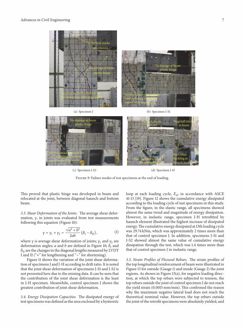