Experimental, numerical, and analytical studies on the...
57
Experimental, numerical, and analytical studies on the seismic response of steel-plate concrete composite shear walls and squat RC shear walls Siamak Epackachi, PhD Assistant Professor Amirkabir University of Technology - Tehran Polytechnic Iranian Society of Steel Structures– October 22, 2017
Transcript of Experimental, numerical, and analytical studies on the...

Experimental, numerical, and analytical studies on the
seismic response of steel-plate concrete composite shear
walls and squat RC shear walls
Siamak Epackachi, PhD
Assistant Professor
Amirkabir University of Technology - Tehran Polytechnic
Iranian Society of Steel Structures– October 22, 2017

1. INTRODUCTION
2. SC WALL APPLICATIONS
3. PRELIMINARY DESIGN AND ANALYSIS OF SC WALLS
4. EXPERIMENTAL PROGRAM
5. EXPERIMENTAL RESULTS
6. NUMERICAL ANALYSIS OF SC WALLS
7. NUMERICAL ANALYSIS RESULTS
8. A PARAMETRIC STUDY: DESIGN OF SC WALLS
9. ANALYTICAL MODELING OF RECTANGULAR SC WALL PANELS
10.MODELING SQUAT REINFORCED CONCRETE SHEAR WALLS FOR SEISMIC ANALYSIS
11.CONCLUSIONS AND FUTURE RESEARCH
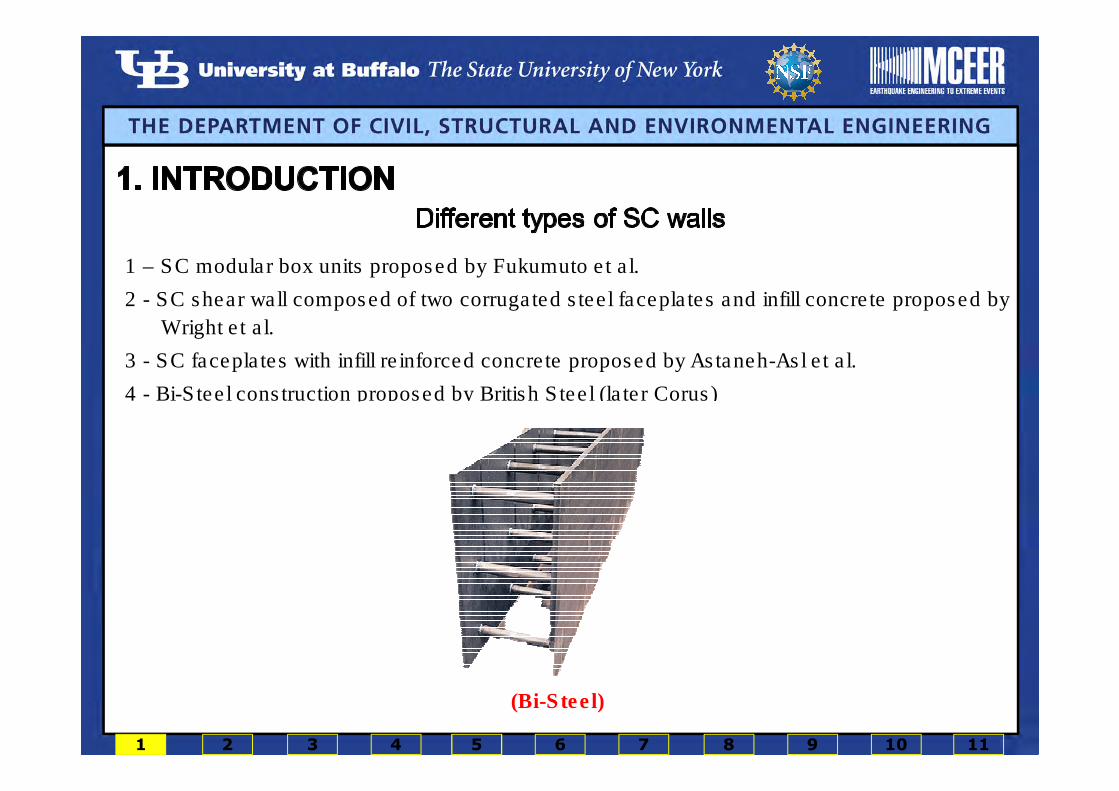
1 – SC modular box units proposed by Fukumuto et al.
2 - SC shear wall composed of two corrugated steel faceplates and infill concrete proposed by
Wright et al.
3 - SC faceplates with infill reinforced concrete proposed by Astaneh-Asl et al.
4 - Bi-Steel construction proposed by British Steel (later Corus)
(SC box units)(SC wall panels with corrugated steel faceplates)(Steel plate walls with RC infill)(Bi-Steel)
1 2 3 4 5 6 7 8 9 10 11

� Focus of the research is flexure- and flexure-shear critical SC wall piers.
� Only loading in the plane of the wall is considered.
� The SC wall piers studied in this research consist of:
• Two steel faceplates
• Infill concrete
• Headed steel studs anchoring the
faceplates to the infill
• Tie rods connecting the two
faceplates through the infill
3 4 5 6 7 8 9 10 111 2

Advantages of SC construction
� General construction
• Elimination of formwork
• Enables large-scale modularization
• Penetrations easily accommodated
• Superior strength and ductility
• Improved quality of placed concrete (SCC)
• Increased construction speed and economy
� Nuclear construction
• Increased shielding capability
• Superior missile/blast resistance
3 4 5 6 7 8 9 10 111 2
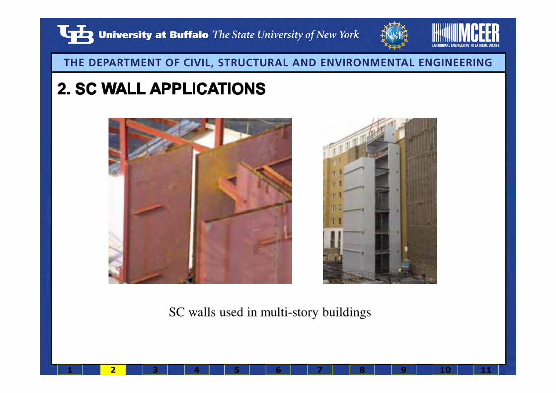
SC walls used in multi-story buildings
1 2 3 4 5 6 7 8 9 10 11

Forty Spring Garden Manchester's Financial District, Corus (2006)
1 2 3 4 5 6 7 8 9 10 11

Dundrum Cinema Lift Core, Corus (2004)
1 2 3 4 5 6 7 8 9 10 11

AP1000, Sanmen, China
1 2 3 4 5 6 7 8 9 10 11
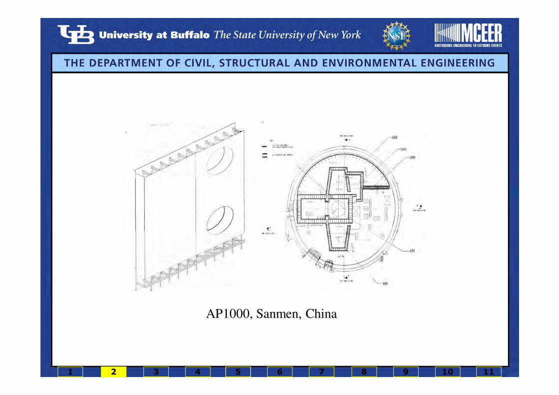
AP1000, Sanmen, China
1 2 3 4 5 6 7 8 9 10 11

� Design of specimens based on a draft version of AISC N690s1
Specimen
Wall dimension
(H×L×T) (in. × in. × in.)
Stud
spacing
(in.)
Tie rod
spacing
(in.)
Reinforcement
ratio
(%)
Faceplate
slenderness
ratio
Day-of-test wall
concrete strength
(ksi)
SC1 60×60×12 4 12 3.1 21 4.5
SC2 60×60×12 - 6 3.1 32 4.5
SC3 60×60×9 4.5 9 4.2 24 5.3
SC4 60×60×9 - 4.5 4.2 24 5.3
� Two 3/16-in. thick steel faceplates were used for all four SC walls.
� The diameter of the studs and tie rods was 0.375 in. for all walls.
� Reinforcement ratio:
� Slenderness ratio:
2 /s
t T
/s
S t
1 2 3 4 5 6 7 8 9 10 11

� XTRACT is a fiber-based cross-sectional analysis software
� Calculation was made to establish the lateral strength of the walls
� Nominal material properties were used
� The shear strengths of SC1 and SC3 corresponding to these flexural strengths were 344 kips and 328 kips, respectively.
� The maximum shear resistance of the walls per the draft Appendix N9 to AISC N690s1,Ozaki et al., and Varma et al. is 870/855/815 kips for SC1/SC2 and 840/855/780 kips forSC3/SC4. The SC walls were identified to be flexure-critical since the shear strengthassociated to the flexural strength of the walls was less than their maximum shearresistance.
1 2 3 4 5 6 7 8 9 10 11
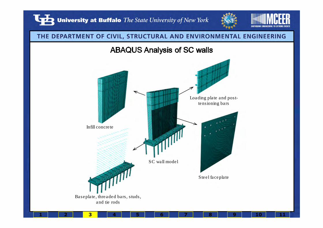
Infill concrete
SC wall model
Baseplate, threaded bars, studs,
and tie rods
Loading plate and post-
tensioning bars
Steel faceplate
1 2 3 4 5 6 7 8 9 10 11

1 2 3 4 5 6 7 8 9 10 11

Construction of the steel shells Foundation construction
Constructed SC walls
1 2 3 4 5 6 7 8 9 10 11

� Studs and tie rods:
• The 3/8-in. and 5/8-in. diameter Nelson studs and tie rods were fabricated from carbon steel
• Nominal yield and ultimate stresses were 50 and 75 ksi, respectively.
� Steel faceplates:
• Three coupons were tested per ASTM A370.
� Infill concrete and foundation:
• Concrete cylinder were tested per ASTM C39-02
at 7, 14, 21, 28 days after concrete casting and
on the days of the SC wall tests
′ =cf 4.4 ksi for SC1/SC2
′ =cf 5.3 ksi for SC3/SC4
Stress-strain relationships of the faceplate coupons
1 2 3 4 5 6 7 8 9 10 11

Loading protocol
1 2 3 4 5 6 7 8 9 10 11

Krypton LEDs
To measure the in-plane and out-of-plane displacements of SC walls
Rosette strain gage
To directly measure strains at discrete locations in the steel faceplates
Rosette strain gages on SC3/SC4Krypton LEDs on SC3/SC4
LVDTs, Temposonic Displacement Transducers, and String Potentiometers
Potentiometers and Temposonics were attached to the ends of the walls to measure in-plane displacement. Potentiometers measured also the out-of-plane displacements of the walls. The
movement of the foundation block relative to the strong floor was monitored using potentiometers.
Layout of the string potentiometers (SP), Temposonic displacement transducers
(TP), and linear variable displacement transducers (LPH and LPV)
1 2 3 4 5 6 7 8 9 10 11

1 2 3 4 5 6 7 8 9 10 11

Concrete
crushing
Concrete
crushing
1 2 3 4 5 6 7 8 9 10 11

SC1 SC2 SC3
SC4
A: Concrete cracking
B: Yielding of the steel faceplates
C: Buckling of the steel faceplates
D: Concrete crushing
E: Fracture of the steel faceplates at their connection to the headed studs
F: Tearing of the steel faceplate above the welded connection of the faceplates to the baseplate
G: Fracture of tie rod
1 2 3 4 5 6 7 8 9 10 11
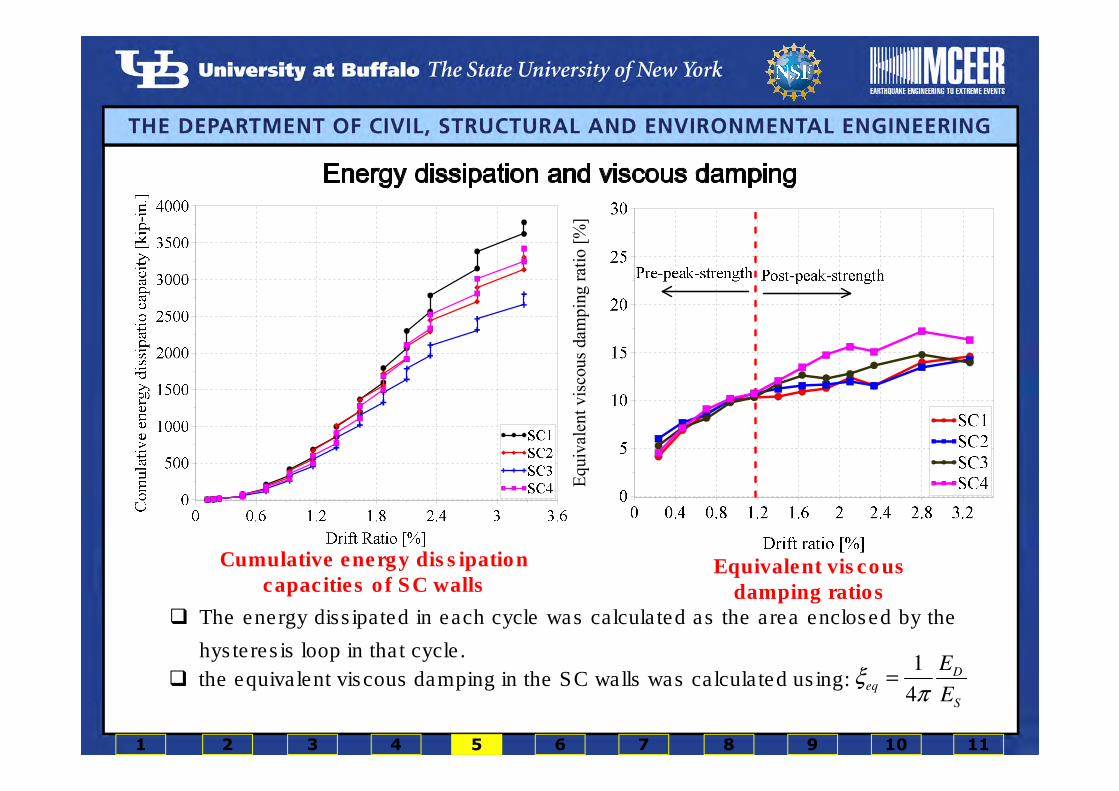
Cumulative energy dissipation capacities of SC walls
Eq
uiv
alen
tv
isco
us
dam
pin
gra
tio
[%]
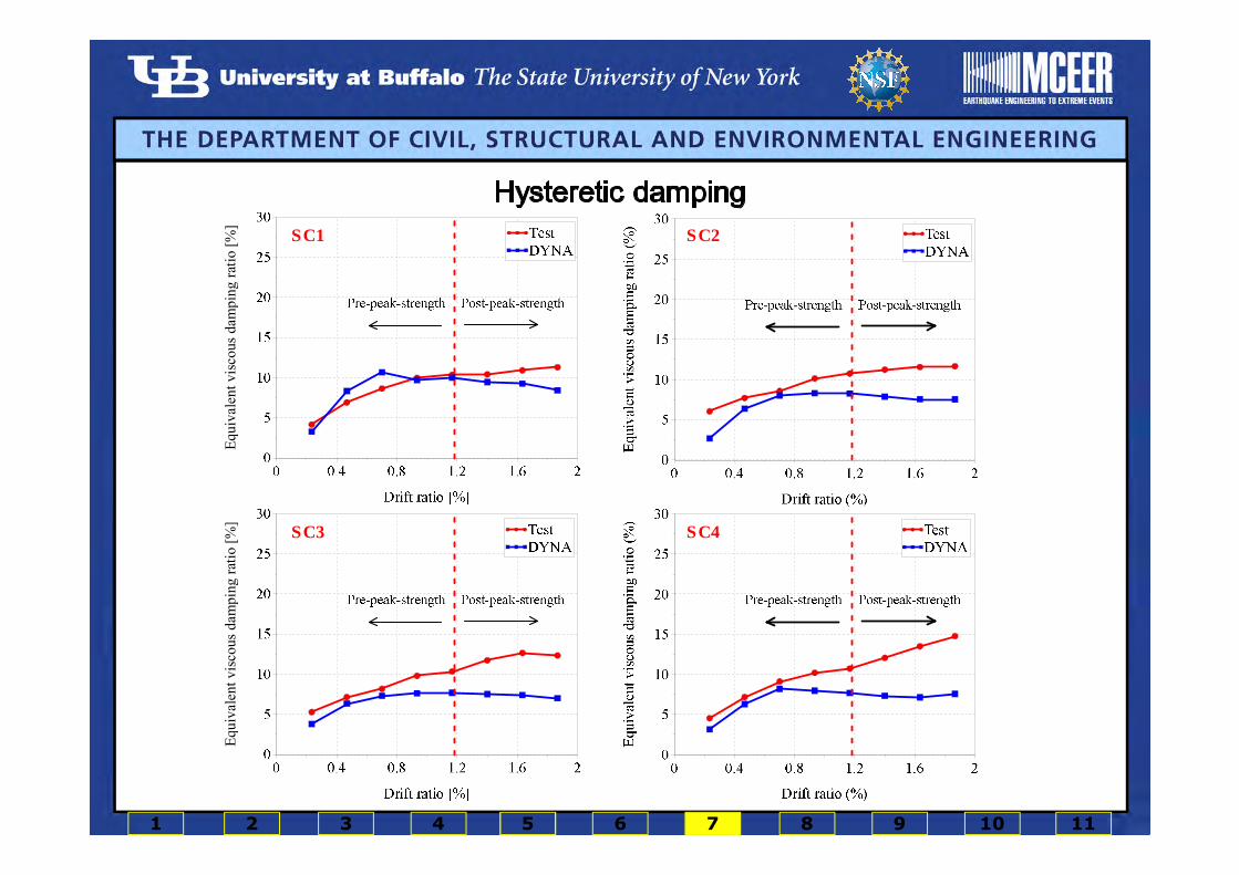
Equivalent viscous damping ratios
� The energy dissipated in each cycle was calculated as the area enclosed by the
hysteresis loop in that cycle.1
4
Deq
S
E
Eξ
π=� the equivalent viscous damping in the SC walls was calculated using:
1 2 3 4 5 6 7 8 9 10 11
SC1 SC2 SC3/SC4
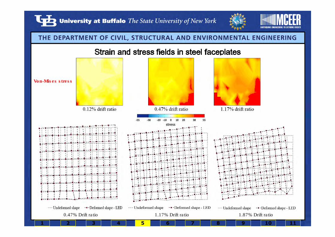
� Normal and shear strains in each square panel were calculated using:
• in-plane displacements measured by Krypton LEDs
• an isoparametric quadrilateral formulation.
� The values of the plane stress components were calculated using:
• the calculated strain field in the steel faceplates
• the elastic properties of the steel faceplates.
Vertical strain
Horizontal strain
Shear strain
Von-Mises stress
0.47% Drift ratio 1.17% Drift ratio 1.87% Drift ratio
1 2 3 4 5 6 7 8 9 10 11
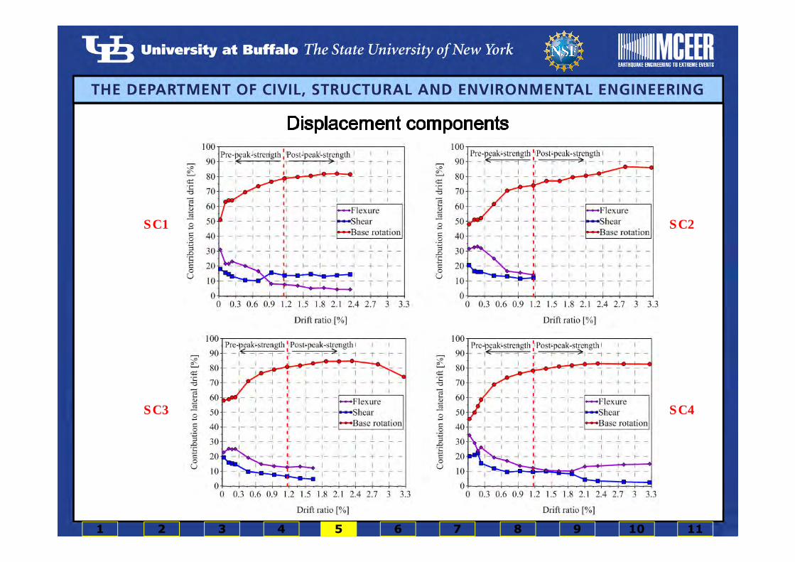
Components of the lateral displacement at top of the wall
Definition of the horizontal strips for the shear displacement calculation
SC1 SC2
SC3 SC4
1 2 3 4 5 6 7 8 9 10 11

1 in.
1 in.
1 in.
1 in.
1 in.
1 2 3 4 5 6 7 8 9 10 11
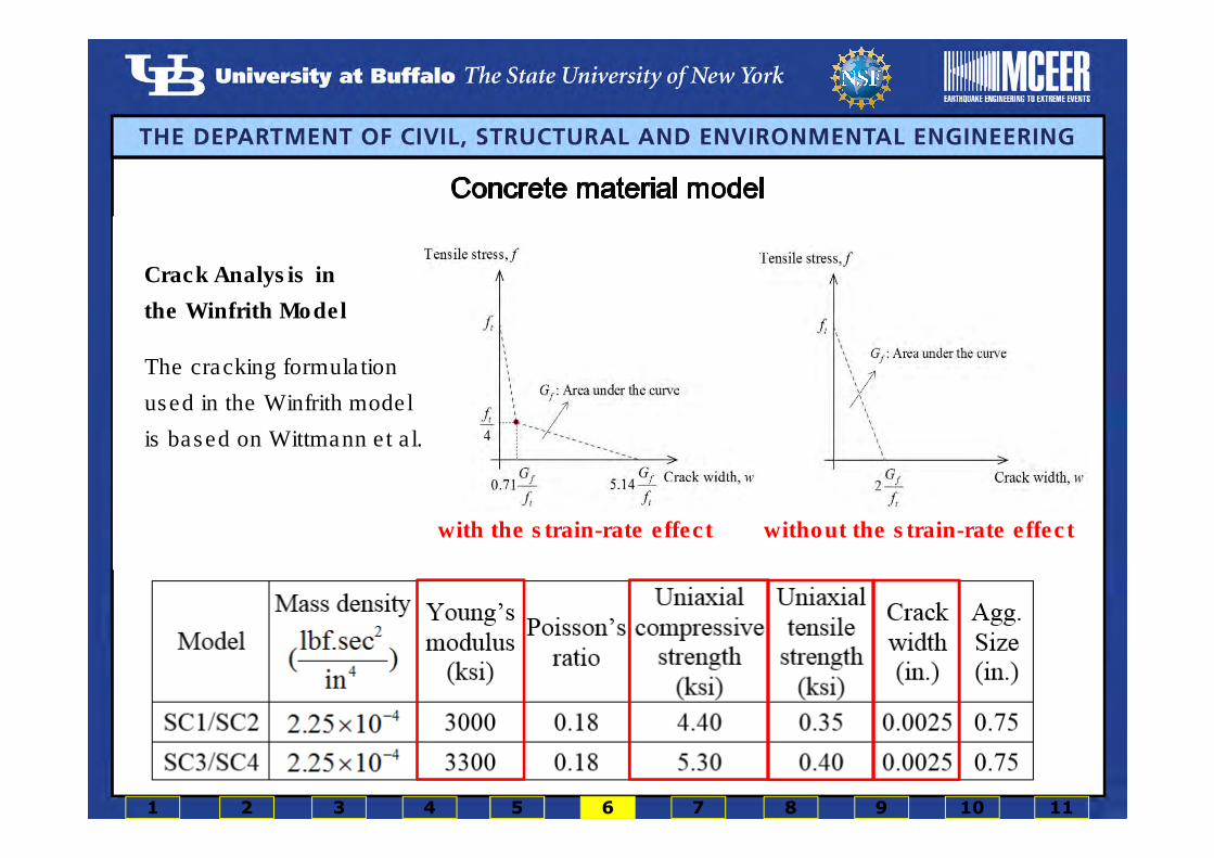
� The smeared crack Winfrith model (MAT085) in LS-DYNA, developed by Broadhouse, was used to
model the infill concrete.
� The Broadhouse model
• provides information on the orientation of the cracking planes (up to three orthogonal cracks for each
element) and the width of the cracks.
• assumes elastic-perfectly plastic behavior in compression and its yield surface is based on the four-
parameter plastic surface of Ottosen model.
• considers shear stress across the crack due to the aggregate interlock.
• smears the rebar.
• The Winfrith model can incorporate strain-rate effects.
Concrete material properties input to the DYNA model
Crack Analysis in
the Winfrith Model
with the strain-rate effect without the strain-rate effect
The cracking formulation
used in the Winfrith model
is based on Wittmann et al.
1 2 3 4 5 6 7 8 9 10 11

� A plastic-damage model, Mat-Plasticity-With-Damage (MAT081) with isotropic hardening,
was used to simulate the nonlinear behavior of the steel faceplates and the connectors.
� Manufacturer-provided information on
the yield and ultimate strengths of
studs and tie rods were used.
Fracture was ignored for the studs
and the tie rods.
� Damage was assumed to begin after
the equivalent plastic strain reached
the strain corresponding to the peak
stress of the stress-strain relationship.
At fracture, the damage index equaled
1.0.
� The average stress-strain relationship, derived from coupon tests, was used to model the
steel faceplates.
Damage = 0
Damage = 1
Steel material properties input to the DYNA model
1 2 3 4 5 6 7 8 9 10 11
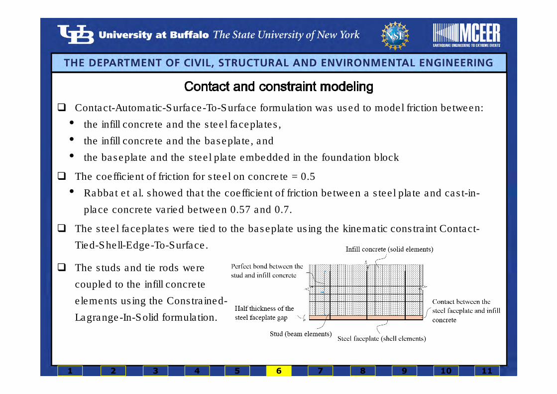
� Contact-Automatic-Surface-To-Surface formulation was used to model friction between:
• the infill concrete and the steel faceplates,
• the infill concrete and the baseplate, and
• the baseplate and the steel plate embedded in the foundation block
� The coefficient of friction for steel on concrete = 0.5
• Rabbat et al. showed that the coefficient of friction between a steel plate and cast-in-
place concrete varied between 0.57 and 0.7.
� The steel faceplates were tied to the baseplate using the kinematic constraint Contact-
Tied-Shell-Edge-To-Surface.
� The studs and tie rods were
coupled to the infill concrete
elements using the Constrained-
Lagrange-In-Solid formulation.
1 2 3 4 5 6 7 8 9 10 11
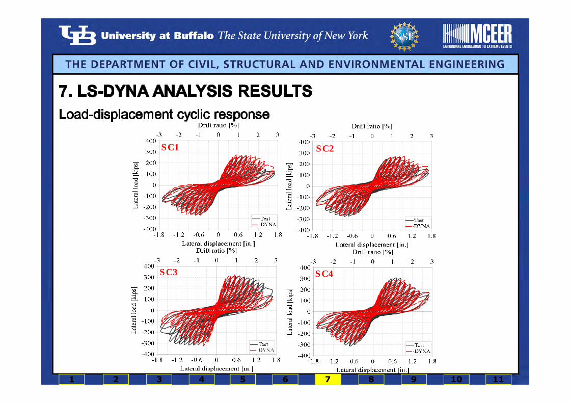
SC1 SC2
SC3 SC4
1 2 3 4 5 6 7 8 9 10 11
Equ
ival
ent
vis
cou
sdam
pin
gra
tio
[%]
Eq
uiv
alen
tv
isco
us
dam
pin
gra
tio
[%]
SC1 SC2
SC3 SC4
1 2 3 4 5 6 7 8 9 10 11

SC1 SC2
SC4SC3
1 2 3 4 5 6 7 8 9 10 11
Analysis and test data at 0.12 % drift ratio
Analysis and test data at 0.18 % drift ratio
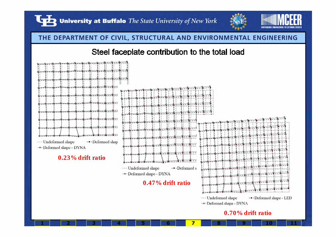
Analysis and test data at 0.23 % drift ratio
0.23% drift ratio
0.47% drift ratio
0.70% drift ratio
1 2 3 4 5 6 7 8 9 10 11

0.70 drift ratio
2.80 drift ratio
Von-Mises stress0.70 drift ratio
2.80 drift ratio
Damage to specimen; test (left panel) and analysis (right panel)
Damage to infill concrete; test (left panel) and analysis (right panel)
1 2 3 4 5 6 7 8 9 10 11

� Six design parameters were considered:
1 2 3 4 5 6 7 8 9 10 11
Levels of the design parameters
Variable Low Intermediate High
Aspect ratio 0.5 (-1) 1.25 (0) 2.0 (+1)
Reinforcement ratio (%) 1.67 (-1) 3.33 (0) 5.0 (+1)
Slenderness ratio 10 (-1) 25 (0) 40 (+1)
Axial load ratio 0 (-1) 0.1 (0) 0.2 (+1)
Yield strength of the steel faceplates (MPa)
235 (-1) 350 (0) 460 (+1)
Concrete compressive strength (MPa)
27.6 (-1) 41.4 (0) 55.2 (+1)
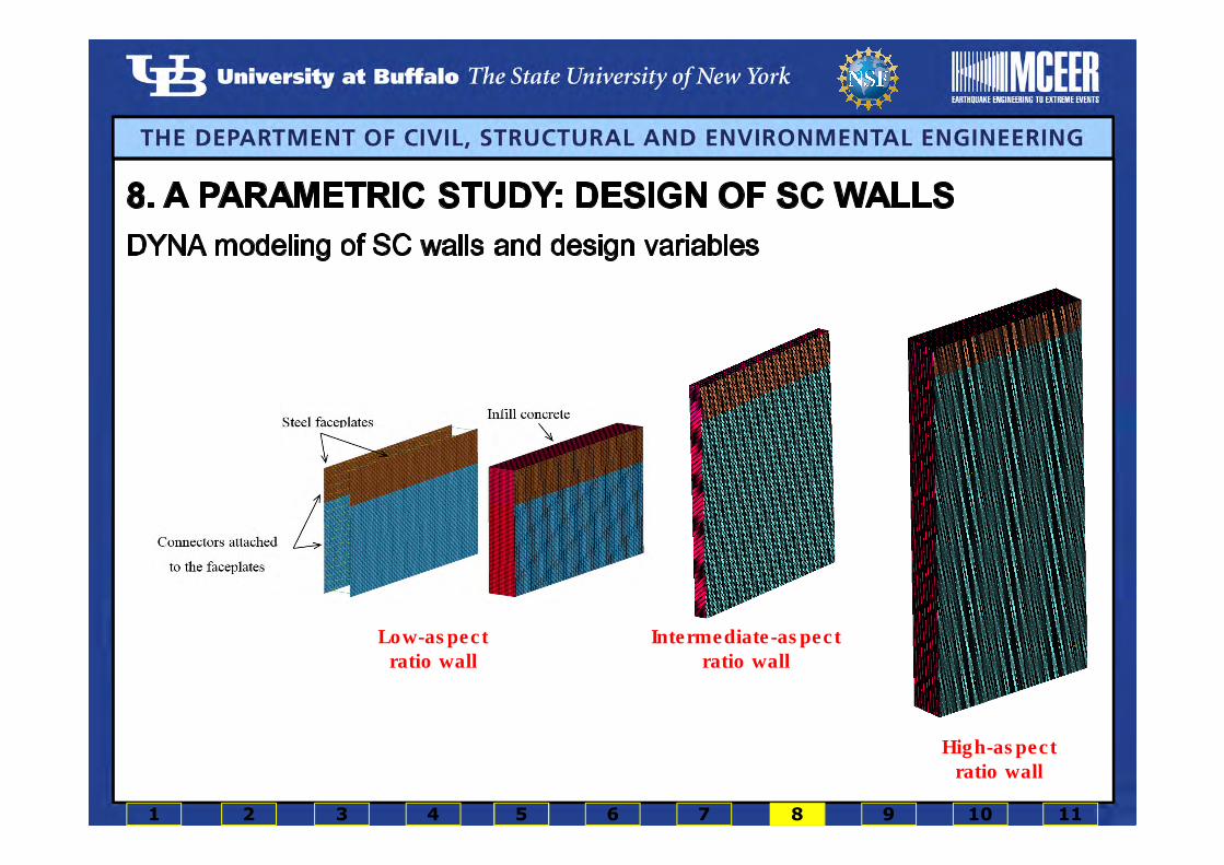
Intermediate-aspect
ratio wall
High-aspect
ratio wall
Low-aspect
ratio wall
1 2 3 4 5 6 7 8 9 10 11

Pe
ak la
tera
l lo
ad
[kip
s]
Pe
ak la
tera
l lo
ad
[kip
s]
Pe
ak la
tera
l lo
ad
[kip
s]
Pe
ak la
tera
l lo
ad
[kip
s]
Pe
ak la
tera
l lo
ad
[kip
s]
Pe
ak la
tera
l lo
ad
[kip
s]
10-in. thick wall with normal-strength concrete
10-in. thick wall with intermediate-strength concrete
20-in. thick wall with normal-
strength concrete
20-in. thick wall with intermediate-
strength concrete
30-in. thick wall with normal-strength concrete
30-in. thick wall with intermediate-
strength concrete
1 2 3 4 5 6 7 8 9 10 11

1 2 3 4 5 6 7 8 9 10 11
1 2 3 4 5 6 7 8 9 10 11
1 2 3 4 5 6 7 8 9 10 11

� A numerical model for calculating the monotonic response of SC wall panels was
developed and verified for the preliminary analysis and design of structures including
these walls.
� The key components of the numerical model for monotonic analysis of rectangular SC
walls are:
• moment-curvature for each wall panel.
• shearing force-shearing strain relationships for each wall panel.
� Assumptions are:
• axial load effects are ignored
• perfect bond between the faceplates and the infill concrete.
Simplified monotonic analysis of SC walls
1 2 3 4 5 6 7 8 9 10 11

In-plane shear response of SC walls
1 2 3 4 5 6 7 10 118 9
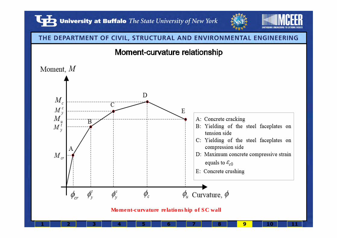
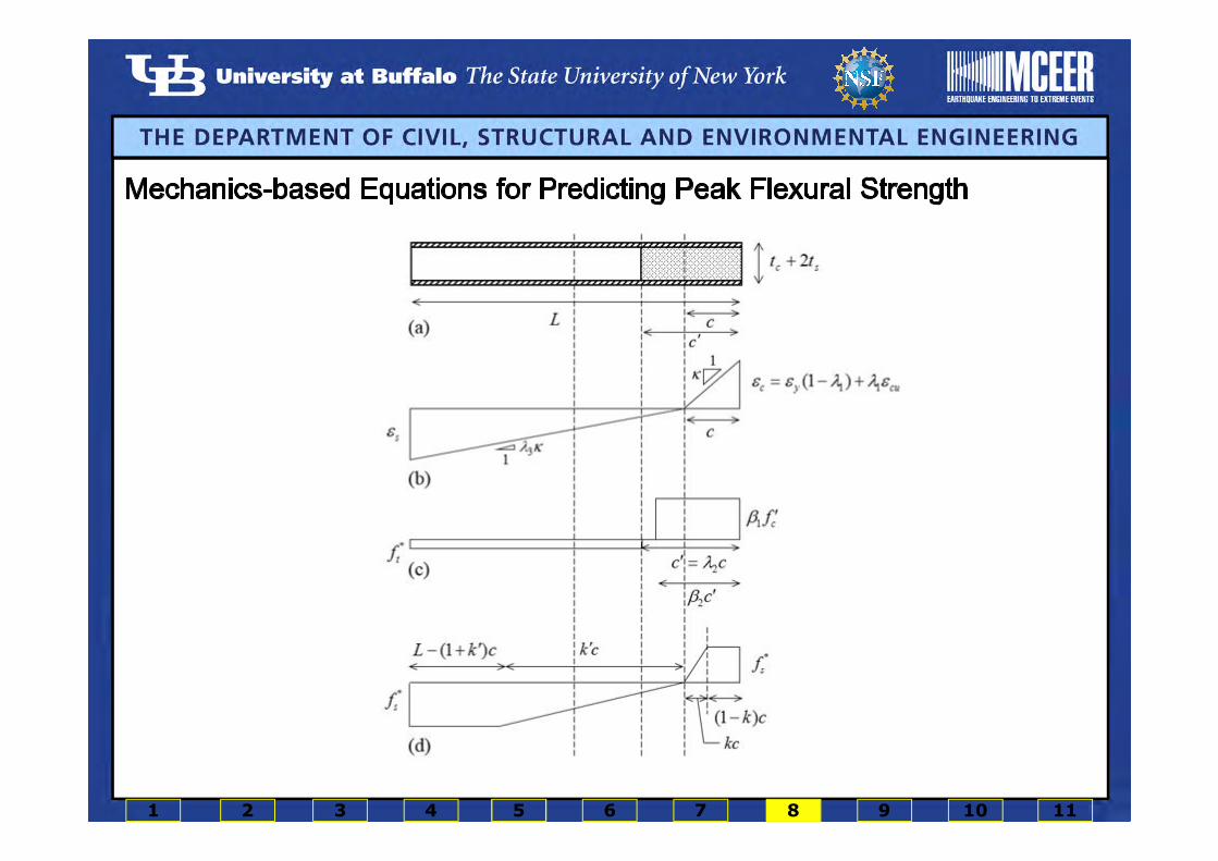
at the onset of concrete cracking
at the onset of the steel faceplate yielding
on the compression side of the wallat maximum concrete compressive strain equals to
the strain corresponding to peak concrete stress
at the onset of the steel faceplate yielding on the tension side of the wall
Moment-curvature relationship of SC wall
1 2 3 4 5 6 7 10 118 9

Force-displacement
relationship for 10-in. thick
walls with 3.8% reinforcement
ratio
Force-displacement
relationship for-10 in. thick
walls with 5.0% reinforcement
ratio
Force-displacement
relationship for 20-in. thick
walls with 1.9% reinforcement
ratio
Force-displacement
relationship for 20-in. thick
walls with 5.0% reinforcement
ratio
Force-displacement
relationship for 30-in. thick
walls with 2.1% reinforcement
ratio
Force-displacement
relationship for 30-in. thick
walls with 5.0% reinforcement
ratio
1 2 3 4 5 6 7 10 118 9

Elevation view of three-story
SC walls subject to uniform
and triangular loadings
Analytically- and
numerically-predicted
responses of three story
SC wall
1 2 3 4 5 6 7 10 118 9

Backbone curve of the IKP model Backbone curve of the MIKP modelCyclic loop of the IKP model Cyclic loop of the MIKP model
1 2 3 4 5 6 7 10 118 9

LAN10-5 LAN20-2 IAN10-5
-0.9 -0.6 -0.3 0 0.3 0.6 0.9
Lateral displacement [in.]
-600-500-400-300-200-100
0100200300400500600
MIKP
DYNA
-1.5 -1 -0.5 0 0.5 1 1.5
Drift ratio [%]
LAH10-5 LAH20-2 IAH10-5
1 2 3 4 5 6 7 10 118 9

1 2 3 4 5 6 7 8 9 10 11
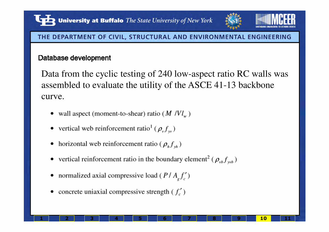
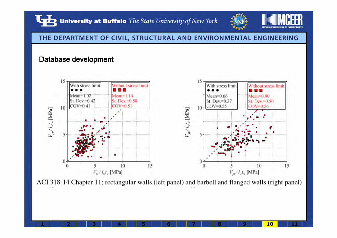
Data from the cyclic testing of 240 low-aspect ratio RC walls was
assembled to evaluate the utility of the ASCE 41-13 backbone
curve.
1 2 3 4 5 6 7 8 9 10 11

1 2 3 4 5 6 7 8 9 10 11

1 2 3 4 5 6 7 8 9 10 11
1 2 3 4 5 6 7 8 9 10 11
Experimental Study
1. The four walls sustained peak lateral loads close to those predicted by pre-test
calculations using commercially available software.
2. Faceplate slenderness ratio does not influence the peak resistance of SC walls in
range of slenderness ratio studied (21 to 32).
3. The distance between the first row of the connectors and the base of the wall has a
significant influence on the post-peak load behavior of these types of SC walls. The
use of a smaller distance between the first row of connectors and the baseplate in
SC1 resulted in slower post-peak strength deterioration in SC1 than in SC2 through
SC4.
4. Pinched hysteresis and loss of stiffness and strength were observed in all four walls
at lateral displacements greater than that corresponding to peak load. Pinching in the
hysteretic response of SC walls was attributed to the cracking and crushing of the infill
concrete, tearing of the steel faceplates, and flexibility at the base of the wall due to
the baseplate connection.
5. The damage progression in the four walls was similar, namely cracking and crushing
of infill concrete at the toes of the walls, outward buckling and yielding of the steel
faceplates near the base of the wall, and tearing of the faceplates at their junction
with the base plate.
6. The damage to the infill concrete was concentrated around the level of the first row of
connectors in all four walls.
7. Tie rods and not headed studs should be used at boundaries of SC walls to improve
behavior at displacements greater than those at peak strength.
8. The equivalent viscous damping for flexure-critical SC walls can be assumed to be
5% of critical at displacements less than that at peak strength and 10% for greater
displacements.
Numerical and Analytical Studies
1. Models of SC walls can be prepared in LS-DYNA to reliably compute monotonic and cyclic
responses that are flexure- or flexure-shear-critical.
2. The DYNA model can be used to predict damage to the infill concrete and the steel
faceplates and thus can be used to develop robust fragility functions for seismic
probabilistic risk assessment.
3. The assumption of perfect bond between the steel faceplates and the infill concrete does
not significantly affect the pre-peak-strength response of the SC walls in the range pf
faceplate slenderness studied here. The post-peak resistance of SC walls is
underpredicted if perfect bond is assumed due to premature fracture of the faceplates.
Perfect bond should not be assumed for finite element analysis.
4. In-plane cyclic response of SC wall is not affected by the choice of the coefficient of friction
between the infill concrete and the steel faceplates.
5. Tie rods instead of shear studs are recommended near the base of an SC wall, where
the faceplates are likely to buckle and high tensile forces are imposed on the
connectors, to improve the seismic response of SC walls.
6. The initial stiffness of SC walls constructed with a baseplate connection to an RC
foundation may be substantially affected by the flexibility of the connection, with a
potential significant impact on the dynamic response of the supported structure.
7. The contribution of the steel faceplates to the total lateral strength increases as the
reinforcement ratio and/or the wall aspect ratio increases.
1 2 3 4 5 6 7 8 9 10 11

1. Studies on flanged SC walls with I- and H-shaped cross sections.
2. Numerical and analytical models for simulation of cyclic response of shear-critical SC
walls.
3. Research on the response of SC walls subjected to both in-plane and out-of-plane
loadings.
4. Development of macro model which can be easily implemented in an engineering
computational platform for practical analyses of SC walls.
5. Identification of the response modification factor, R, for SC walls.
6. Generation of the fragility functions.
7. Comparison studies on SC and RC walls with identical shear span-to-depth ratios and
reinforcement ratios.
1 2 3 4 5 6 7 8 9 10 11

Journal articles:
Epackachi, S., Whittaker, A.S, and Aref, A. (2016). “Seismic analysis and design of steel-plate concrete composite shear wall piers”
Engineering Structures, DOI: 10.1016/j.engstruct.2016.12.024.
Epackachi, S., Whittaker, A.S, Varma, A.H., and Kurt, E.G. (2015). “Finite element modeling of steel-plate concrete composite wall
piers” Engineering Structures, DOI: 10.1016/j.engstruct.2015.06.02.
Farhidzadeh, A., Epackachi, S., Salamone, S., Whittaker, A.S. (2015). “Bayesian decision and mixture models for AE monitoring of
steel-concrete composite shear walls” Smart Materials and Structures, DOI: 10.1088/0964-1726/24/11/115028.
Epackachi, S., Whittaker, A.S, and Huang, Y.N. (2014). “Analytical modeling of rectangular SC wall panels” Journal of
Construction Steel Research, DOI:10.1016/j.jcsr.2014.10.016.
Epackachi, S., Nguyen, N.H., Kurt, E.G., Whittaker, A.S, and Varma, A.H. (2013). “In-plane seismic behavior of rectangular steel-
plate composite wall piers” Journal of Structural Engineering (ASCE), DOI: 10.1061/(ASCE)ST.1943-541X.0001148.
1 2 3 4 5 6 7 8 9 10 11
Conference proceedings:
Epackachi, S., and Whittaker, A. S. (2017). “Effective lateral stiffness of steel-plate concrete composite wall piers” Trans., 24th Int.
Conf. on Structural Mechanics in Reactor Technology (SMiRT 24), Busan, Korea.
Epackachi, S., Whittaker, A. S. (2017). “Design of steel-plate concrete composite wall piers” Trans., 16th World Conference on
Earthquake Engineering, Chile.
Terranova, B., Epackachi, S., and Whittaker, A. S. (2017). “Effect of out-of-plane loading on the in-plane response of SC wall
piers” Trans., 16th World Conference on Earthquake Engineering, Chile.
Epackachi, S., Whittaker, A. S., and Varma, A.H. (2015). “An analytical model for a baseplate connection of an SC wall to an RC
foundation” Proc., 8th International Conference on Steel Structures, Jeju, South Korea.
Epackachi, S., and Whittaker, A. S. (2015). “Numerical investigation of the in-plane behavior of low-aspect ratio reinforced
concrete shear walls” Trans., 23rd Int. Conf. on Structural Mechanics in Reactor Technology (SMiRT 23), Manchester, UK.
Epackachi, S., Whittaker, A. S. and Varma, A.H. (2015). “Experimental behavior of flexure critical steel-Plate composite SC shear
walls” Trans., 23rd Int. Conf. on Structural Mechanics in Reactor Technology (SMiRT 23), Manchester, UK.
Chang, C.C., Huang, Y.N., Chen, B.A., Epackachi, S., and Whittaker, A. S. (2015). “An experimental study for in-plane cyclic
behavior of low aspect-ratio SC wall piers” Trans., 23rd Int. Conf. on Structural Mechanics in Reactor Technology (SMiRT 23),
Manchester, UK.
1 2 3 4 5 6 7 8 9 10 11

Kurt, E.G., Varma, A.H., Epackachi, S., and Whittaker, A.S. (2015). “Rectangular SC wall piers: summary of seismic behavior and
design” Trans., 2015 Structures Congress (ASCE), Portland, Oregon, USA.
Epackachi, S., Whittaker, A.S., and Varma, A.H. (2014). “Numerical and experimental investigation on in-plane behavior of steel-
concrete composite walls” Trans., 2014 Structures Congress (ASCE), Boston, MA, USA.
Nguyen, N.H., Epackachi, S., Kurt, E.G., Whittaker, A.S., and Varma, A.H. (2013). “In-plane shear response of steel-concrete
composite shear walls: results of experiments”, Trans., Australian Earthquake Engineering Society 2013 Conference, Hobart,
Tasmania, Australia.
Epackachi, S., Nguyen, N. H., Kurt, E. G., Whittaker, A. S. and Varma, A.H. (2013). “An experimental study of the in-plane shear
response of steel concrete composite walls,” Trans., 22nd Int. Conf. on Structural Mechanics in Reactor Technology (SMiRT 22),
San Francisco, California, USA, Paper ID #938.
1 2 3 4 5 6 7 8 9 10 11