Exercise 1 3 Point Bending Using the Static Structural · PDF file3-Point Bending Using the...
15
U. Simon, F. Niemeyer SiSo Aufgabe 1 Page 1 of 15 Exercise 1 3-Point Bending Using the Static Structural Module of Ansys Workbench 14.0 Contents Learn how to … ................................................................................................................................................................................1 Given ...................................................................................................................................................................................................2 Questions ...........................................................................................................................................................................................2 Taking advantage of symmetries...............................................................................................................................................2 A. Getting started...........................................................................................................................................................................3 A.1 Choose the correct ANSYS license .............................................................................................................................3 A.2 Start the FE software ANSYS .......................................................................................................................................3 B. Preprocessor (Setting up the Model).................................................................................................................................4 B.1 Build the Geometry Using DesignModeler Module ...............................................................................................4 B.2 Material Properties ..........................................................................................................................................................6 i. Define Material Properties .......................................................................................................................................6 B.3 Meshing ................................................................................................................................................................................8 B.4 Applying Loads and Boundary Conditions ...............................................................................................................9 i. Boundary Conditions ..................................................................................................................................................9 ii. Applying the Loads ......................................................................................................................................... 10 A. Solving ....................................................................................................................................................................................... 11 a. Contour Plot of Deformed Shape ............................................................................................................................ 11 b. Contour Plot: X-Component of Total Strain ........................................................................................................ 12 c. Contour Plot X-Component of Stress ..................................................................................................................... 13 d. Contour Plot: Von-Mises Equivalent Stress ......................................................................................................... 15 Answering the Questions: ......................................................................................................................................................... 15 Learn how to … use the ANSYS Workbench DesignModeler build a model take advantage of symmetries perform a full analysis consisting of pre-processing, solution and post-processing
Transcript of Exercise 1 3 Point Bending Using the Static Structural · PDF file3-Point Bending Using the...

U. Simon, F. Niemeyer SiSo Aufgabe 1
Page 1 of 15
Exercise 1
3-Point Bending Using the Static Structural Module of
Ansys Workbench 14.0
Contents Learn how to … ................................................................................................................................................................................1 Given ...................................................................................................................................................................................................2 Questions ...........................................................................................................................................................................................2 Taking advantage of symmetries...............................................................................................................................................2 A. Getting started ...........................................................................................................................................................................3
A.1 Choose the correct ANSYS license .............................................................................................................................3 A.2 Start the FE software ANSYS .......................................................................................................................................3
B. Preprocessor (Setting up the Model).................................................................................................................................4 B.1 Build the Geometry Using DesignModeler Module ...............................................................................................4 B.2 Material Properties ..........................................................................................................................................................6
i. Define Material Properties .......................................................................................................................................6 B.3 Meshing ................................................................................................................................................................................8 B.4 Applying Loads and Boundary Conditions ...............................................................................................................9
i. Boundary Conditions ..................................................................................................................................................9 ii. Applying the Loads ......................................................................................................................................... 10
A. Solving ....................................................................................................................................................................................... 11 a. Contour Plot of Deformed Shape ............................................................................................................................ 11 b. Contour Plot: X-Component of Total Strain ........................................................................................................ 12 c. Contour Plot X-Component of Stress ..................................................................................................................... 13 d. Contour Plot: Von-Mises Equivalent Stress ......................................................................................................... 15
Answering the Questions: ......................................................................................................................................................... 15
Learn how to …
use the ANSYS Workbench DesignModeler
build a model
take advantage of symmetries
perform a full analysis consisting of pre-processing, solution and post-processing

U. Simon, F. Niemeyer SiSo Aufgabe 1
Page 2 of 15
Given
Beam under 3-point bending with a centric applied force F as shown in Figure 1
F
L
t h
w
Figure 1: Beam under 3-point bending.
Relevant geometrical and material data for our problem are given in Table 1:
F
L
h
t
E
ν
σyield
= 500,000 N
= 2,000 mm
= 60 mm
= 20 mm
= 210,000 N/mm2
= 0.3
= 235 N/mm2
Applied force
Length of the beam
Height of the beam cross section
Thickness of the beam cross section
Young’s modulus
Poisson’s ration
Allowable stress: yield stress of steel
Table 1: Geometry and material data.
Questions
Due to this classic 2-dimensional mechanical problem we can state two questions:
1. Will the beam break and were would it start breaking?
2. If not, what would be the maximum deflection w?
Taking advantage of symmetries
Can we take advantage of symmetries? Please, draw a simplified beam model which
takes advantage of symmetry!
Figure 2: Space for drawing of simplified beam model taking advantage of symmetry.

U. Simon, F. Niemeyer SiSo Aufgabe 1
Page 3 of 15
A. Getting started
A.1 Choose the correct ANSYS license
Before starting ANSYS Workbench, run “User License Preferences 14.0” and ensure that “ANSYS Academic Teaching Advanced” is the preferred license (Figure 3).
Figure 3: Select “ANSYS Academic Teaching Advanced” as the preferred license by moving it to the top of
the list.
A.2 Start the FE software ANSYS
Start ANSYS Workbench by running “Workbench 14.0” (Figure 4).
Figure 4: Starting ANSYS Workbench 14.0

U. Simon, F. Niemeyer SiSo Aufgabe 1
Page 4 of 15
B. Preprocessor (Setting up the Model)
Figure 5: Interface of ANSYS Workbench 14.0
B.1 Build the Geometry Using DesignModeler Module
To begin; drag the Static Structural Module from the Analysis Systems toolbox and
drop into the Project Schematic (Figure 6) and double click on the Geometry sub-
module to open the DesignModeler. When asked, choose the desired unit system.
Choose Create → Primitives → Box from the main menu to create a beam by entering
the desired dimensions in the Details box (Figure 7). Hit the Generate button to
actually create the geometry.
When specifying the dimension of the beam, make sure that the origin of the coordinate
system is located on the center of the beam’s cross section. The beam axis must be
oriented along the global x-axis.

U. Simon, F. Niemeyer SiSo Aufgabe 1
Page 5 of 15
Figure 6: Drag-and-drop the Static Structural module to create a new analysis.
Figure 7: The beam on the DesignModeler
Note that ANSYS Workbench saves the model automatically; you can simply close
DesignModeler now and continue with the next step.

U. Simon, F. Niemeyer SiSo Aufgabe 1
Page 6 of 15
B.2 Material Properties
i. Define Material Properties
Materials define the mechanical behavior of the FE model. We will use a simple linear-
elastic, isotropic material model. In the project schematic, right click on Engineering
Data to open a context menu and choose Edit… (Figure 8).
Figure 8: Edit engineering data
Enter a name for your new material in row 4 (Figure 9).
Figure 9: Naming the new material
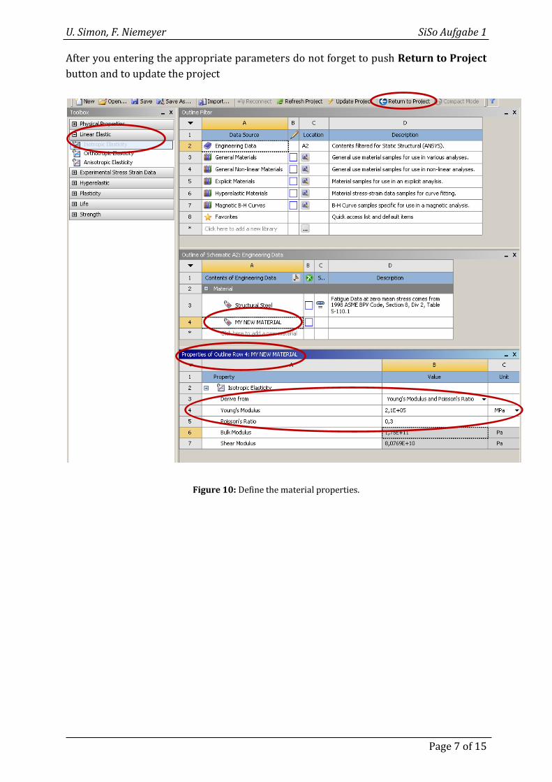
Choose the simplest available material model by dragging the item Isotropic Elasticity
from the Toolbox and dropping it onto the row with your newly defined material
(Figure 10). Isotropic Elasticity requires certain material parameters: Young’s
Modulus and Poisson’s Ratio.
U. Simon, F. Niemeyer SiSo Aufgabe 1
Page 7 of 15
After you entering the appropriate parameters do not forget to push Return to Project
button and to update the project
Figure 10: Define the material properties.

U. Simon, F. Niemeyer SiSo Aufgabe 1
Page 8 of 15
B.3 Meshing
To mesh the solid body select double click the Model sub-module in the Project
schematic to open the Mechanical module (Figure 11).
Figure 11: Starting the meshing and analysis module
Right click on Mesh in the Structure Tree and select a meshing method (Figure 12).
Mesh (right click) Insert Mapped Mesh
Figure 12: Setup meshing details

U. Simon, F. Niemeyer SiSo Aufgabe 1
Page 9 of 15
At this point focus on the Details box and select the geometry (all 6 faces) and do not
forget to update the project; then click the Generate button.
Figure 13: Meshed body
B.4 Applying Loads and Boundary Conditions
i. Boundary Conditions
To setup the necessary support:
Structure Tree Static-Mechanic (right click) Insert Fixed Support
Select the Face you want to assign as a fixed support.
Figure 14: Fixed Face of the body

U. Simon, F. Niemeyer SiSo Aufgabe 1
Page 10 of 15
ii. Applying the Loads
Structure Tree Static-Mechanic (right click) Insert Force
Select the Face you want to assign a force on this surface.
Assign the components of the force vector. Now the problem is ready to be solved.
Figure 15: Applied force
Figure 16: Fixed face of the body and applied force

U. Simon, F. Niemeyer SiSo Aufgabe 1
Page 11 of 15
A. Solving
To solve the problem add some solving tools to the Solution node which is part of the
Structure tree.
Solution (right click) Total Deformation
Solution (right click) Total Strain
Solution (right click) Total Stress
Solution (right click) Von-Mises Equivalent Stress
Click Solve
Figure 17: Required solving tools
a. Contour Plot of Deformed Shape
Figure 17: SCALED Displacement solution (z direction) of the beam (with too high force).

U. Simon, F. Niemeyer SiSo Aufgabe 1
Page 12 of 15
Figure 18: UNSCALED Displacement solution (z direction) of the beam (with too high force).
Correcting the Model:
The value of the applied force was erroneously too high and should be corrected from
500,000 to 5,000 Newton.
Structure tree Force Details
Change the value of the force 500,000 to 5,000 N and click to Solve.
Figure 19: Deformed shape of the beam resulting from corrected force.
b. Contour Plot: X-Component of Total Strain
Structure Tree Total Strain
and
Details Direction X-axis

U. Simon, F. Niemeyer SiSo Aufgabe 1
Page 13 of 15
Figure 17: Details of total strain
Figure 20: Contour plot of x-component of total strain.
c. Contour Plot X-Component of Stress
Structure Tree Total Stress
and
Details Direction X-axis

U. Simon, F. Niemeyer SiSo Aufgabe 1
Page 14 of 15
Figure 21: Details of total stress
Figure 22: Contour plot of x-component of stress.

U. Simon, F. Niemeyer SiSo Aufgabe 1
Page 15 of 15
d. Contour Plot: Von-Mises Equivalent Stress
Figure 22: Contour plot of Von-Mises equivalent stress.
Answering the Questions:
1 Will the beam break and were would it start breaking?
With the corrected force (F = 5,000 N) the beam will not break. The maximal predicted
von Mises stress reaches values of σpred = 206 N/mm2, whereas the ultimate yield stress
σyield = 235 N/mm2 is higher. That means the failure criterion σpred > σyield is not fulfilled.
However, the difference between the two values is small. In many technical applications
the factor of security should be 2.0 or even higher. The factor of security σyield/σpred
reached in our example is much smaller.
The critical region, were we would expect the beginning of a failure, is located at the left
end of the half beam, Symbol MX) at the location of maximum stresses. For the full
length beam the critical region would lay in the middle where the force was applied
(Figure 1).
2 If not, what would be the maximum deflection w?
We predicted a maximum deflection of w = 11 mm appearing at the free end (right side,
symbol MX) of the simplified half model. The full length beam under 3-point-bending
(Figure 1) will show a maximum deflection of the same amount in the middle.