Examining the effect of adverse geological conditions on ...
11
Full Length Article Examining the effect of adverse geological conditions on jamming of a single shielded TBM in Uluabat tunnel using numerical modeling Rohola Hasanpour a, * , Jürgen Schmitt b , Yilmaz Ozcelik c , Jamal Rostami d a Institute for Tunneling and Construction Management, Ruhr-University Bochum, Bochum, Germany b Department of Civil Engineering, Darmstadt University of Applied Science, Darmstadt, Germany c Department of Mining Engineering, Hacettepe University, Ankara, Turkey d Department of Mining Engineering, Colorado School of Mines, Golden, USA article info Article history: Received 21 February 2017 Received in revised form 16 May 2017 Accepted 30 May 2017 Available online 10 November 2017 Keywords: Single shielded tunnel boring machine (TBM) Numerical modeling Shield jamming Squeezing ground Uluabat tunnel abstract Severe shield jamming events have been reported during excavation of Uluabat tunnel through adverse geological conditions, which resulted in several stoppages at advancing a single shielded tunnel boring machine (TBM). To study the jamming mechanism, three-dimensional (3D) simulation of the machine and surrounding ground was implemented using the finite difference code FLAC3D. Numerical analyses were performed for three sections along the tunnel with a higher risk for entrapment due to the combination of overburden and geological conditions. The computational results including longitudinal displacement contours and ground pressure profiles around the shield allow a better understanding of ground behavior within the excavation. Furthermore, they allow realistically assessing the impact of adverse geological conditions on shield jamming. The calculated thrust forces, which are required to move the machine forward, are in good agreement with field observations and measurements. It also proves that the numerical analysis can effectively be used for evaluating the effect of adverse geological environment on TBM entrapments and can be applied to prediction of loads on the shield and pre- estimating of the required thrust force during excavation through adverse ground conditions. Ó 2017 Institute of Rock and Soil Mechanics, Chinese Academy of Sciences. Production and hosting by Elsevier B.V. This is an open access article under the CC BY-NC-ND license (http://creativecommons.org/ licenses/by-nc-nd/4.0/). 1. Introduction Despite significant progresses in the development of shielded tunnel boring machines (TBMs), the use of these machines through weak grounds and adverse geological conditions is still risky. The presence of the shield limits accesses to the tunnel walls in order to observe geological conditions and ground behaviors. Meanwhile, the excessive convergence of weak ground under high in situ stresses can impose high levels of load on the shield, which makes the machine susceptible to entrapment in weak rocks, especially under large overburden. It results in machine jamming and im- poses high economic costs on tunneling companies (Farrokh and Rostami, 2008). The complex interactions between rock mass, tunneling ma- chine and its system components, and tunnel lining can be investigated in detail using three-dimensional (3D) numerical modeling that takes into account the main interaction parameters of ground, machine and tunnel (Cantieni and Anagnostou, 2009). Various studies have focused on computational modeling of mechanized tunneling in long and deep tunnels through adverse ground conditions. For example, Einstein and Bobet (1997), Lombardi and Panciera (1997), Graziani et al. (2007), Sterpi and Gioda (2007), Wittke et al. (2007), Ramoni and Anagnostou (2007), Amberg (2009), Schmitt (2009) and Zhao et al. (2012) conducted numerical investigations on TBM tunneling using different computational methods. Furthermore, Ramoni and Anagnostou (2010) developed dimensionless design nomograms using the results obtained from computational analyses, which allow a quick preliminary assessment of the thrust force required in order to overcome shield skin friction and avoid jamming of the shield. Several studies were also reported in relation to the applications of computational analysis at shallow tunnels such as the numerical investigations by Finno and Clough (1985), Bernat and Cambou (1998) and Abu-Farsakh and Voyiadjis (1999) using two- dimensional (2D) approaches in their analyses. Furthermore, to * Corresponding author. E-mail address: [email protected] (R. Hasanpour). Peer review under responsibility of Institute of Rock and Soil Mechanics, Chi- nese Academy of Sciences. Contents lists available at ScienceDirect Journal of Rock Mechanics and Geotechnical Engineering journal homepage: www.rockgeotech.org Journal of Rock Mechanics and Geotechnical Engineering 9 (2017) 1112e1122 https://doi.org/10.1016/j.jrmge.2017.05.010 1674-7755 Ó 2017 Institute of Rock and Soil Mechanics, Chinese Academy of Sciences. Production and hosting by Elsevier B.V. This is an open access article under the CC BY-NC-ND license (http://creativecommons.org/licenses/by-nc-nd/4.0/).
Transcript of Examining the effect of adverse geological conditions on ...

lable at ScienceDirect
Journal of Rock Mechanics and Geotechnical Engineering 9 (2017) 1112e1122
Contents lists avai
Journal of Rock Mechanics andGeotechnical Engineering
journal homepage: www.rockgeotech.org
Full Length Article
Examining the effect of adverse geological conditions on jamming of asingle shielded TBM in Uluabat tunnel using numerical modeling
Rohola Hasanpour a,*, Jürgen Schmitt b, Yilmaz Ozcelik c, Jamal Rostami d
a Institute for Tunneling and Construction Management, Ruhr-University Bochum, Bochum, GermanybDepartment of Civil Engineering, Darmstadt University of Applied Science, Darmstadt, GermanycDepartment of Mining Engineering, Hacettepe University, Ankara, TurkeydDepartment of Mining Engineering, Colorado School of Mines, Golden, USA
a r t i c l e i n f o
Article history:Received 21 February 2017Received in revised form16 May 2017Accepted 30 May 2017Available online 10 November 2017
Keywords:Single shielded tunnel boring machine(TBM)Numerical modelingShield jammingSqueezing groundUluabat tunnel
* Corresponding author.E-mail address: [email protected] (R. HasaPeer review under responsibility of Institute of R
nese Academy of Sciences.
https://doi.org/10.1016/j.jrmge.2017.05.0101674-7755 � 2017 Institute of Rock and Soil MechanCC BY-NC-ND license (http://creativecommons.org/li
a b s t r a c t
Severe shield jamming events have been reported during excavation of Uluabat tunnel through adversegeological conditions, which resulted in several stoppages at advancing a single shielded tunnel boringmachine (TBM). To study the jamming mechanism, three-dimensional (3D) simulation of the machineand surrounding ground was implemented using the finite difference code FLAC3D. Numerical analyseswere performed for three sections along the tunnel with a higher risk for entrapment due to thecombination of overburden and geological conditions. The computational results including longitudinaldisplacement contours and ground pressure profiles around the shield allow a better understanding ofground behavior within the excavation. Furthermore, they allow realistically assessing the impact ofadverse geological conditions on shield jamming. The calculated thrust forces, which are required tomove the machine forward, are in good agreement with field observations and measurements. It alsoproves that the numerical analysis can effectively be used for evaluating the effect of adverse geologicalenvironment on TBM entrapments and can be applied to prediction of loads on the shield and pre-estimating of the required thrust force during excavation through adverse ground conditions.� 2017 Institute of Rock and Soil Mechanics, Chinese Academy of Sciences. Production and hosting byElsevier B.V. This is an open access article under the CC BY-NC-ND license (http://creativecommons.org/
licenses/by-nc-nd/4.0/).
1. Introduction
Despite significant progresses in the development of shieldedtunnel boring machines (TBMs), the use of these machines throughweak grounds and adverse geological conditions is still risky. Thepresence of the shield limits accesses to the tunnel walls in order toobserve geological conditions and ground behaviors. Meanwhile,the excessive convergence of weak ground under high in situstresses can impose high levels of load on the shield, which makesthe machine susceptible to entrapment in weak rocks, especiallyunder large overburden. It results in machine jamming and im-poses high economic costs on tunneling companies (Farrokh andRostami, 2008).
The complex interactions between rock mass, tunneling ma-chine and its system components, and tunnel lining can be
npour).ock and Soil Mechanics, Chi-
ics, Chinese Academy of Sciencescenses/by-nc-nd/4.0/).
investigated in detail using three-dimensional (3D) numericalmodeling that takes into account the main interaction parametersof ground, machine and tunnel (Cantieni and Anagnostou, 2009).Various studies have focused on computational modeling ofmechanized tunneling in long and deep tunnels through adverseground conditions. For example, Einstein and Bobet (1997),Lombardi and Panciera (1997), Graziani et al. (2007), Sterpi andGioda (2007), Wittke et al. (2007), Ramoni and Anagnostou(2007), Amberg (2009), Schmitt (2009) and Zhao et al. (2012)conducted numerical investigations on TBM tunneling usingdifferent computational methods. Furthermore, Ramoni andAnagnostou (2010) developed dimensionless design nomogramsusing the results obtained from computational analyses, whichallow a quick preliminary assessment of the thrust force required inorder to overcome shield skin friction and avoid jamming of theshield.
Several studies were also reported in relation to the applicationsof computational analysis at shallow tunnels such as the numericalinvestigations by Finno and Clough (1985), Bernat and Cambou(1998) and Abu-Farsakh and Voyiadjis (1999) using two-dimensional (2D) approaches in their analyses. Furthermore, to
. Production and hosting by Elsevier B.V. This is an open access article under the

Fig. 1. (a) Project area of Uluabat power tunnel, and (b) Geological profile of Uluabat tunnel alignment and locations of hand-mined galleries to release the jammed TBM (modifiedfrom Bilgin and Algan, 2012).
R. Hasanpour et al. / Journal of Rock Mechanics and Geotechnical Engineering 9 (2017) 1112e1122 1113
examine the stressestrain behavior of the ground, advanced 3Dmodels have been developed by Mansour (1996), van Dijk andKaalberg (1998), Komiya et al. (1999), Dias et al. (2000) and Meliset al. (2002). Kasper and Meschke (2004, 2006a) studied the in-fluence of TBM operational and design parameters for a shallowtunnel advance in the homogeneous, soft, cohesive soil below thegroundwater table using a full 3D numerical simulation.
Results found by means of 3D finite element models have beenpresented by Lee and Rowe (1991), Augarde and Burd (2001) andMroueh and Shahrour (2008). They utilized full 3D coupled-consolidation analyses for modeling of the excavation process.Moreover, the impact of gap grouting properties, cover depth andface pressure can be found in the studies by Kasper and Meschke(2006b). Recently, Chakeri et al. (2011), Hasanpour et al. (2012)and Lambrughi et al. (2012) presented a 3D numerical model us-ing the finite difference code FLAC3D for mechanized excavations,which was capable of simulating a tunnel excavationwhen an earthpressure balance (EPB)-TBM was used. In addition, a full 3Dmodeling of tunneling using a double-shielded TBMwas conductedin the studies by Hasanpour (2014) and Hasanpour et al. (2014,2015, 2016). They considered all the main machine componentsand performance parameters in their numerical investigations.
In this study, 3D modeling of a single shielded TBM with EPBmode, which was used for excavation of Uluabat power tunnelthrough rock masses, is presented. The formations include meta-siltstone, graphitic schist, meta-claystone and metadetritics withclay matrix that exhibit squeezing behavior. The model considers
the main interaction components of the machine, ground proper-ties, performance and tunnel parameters that distinguish it fromother 3D models developed for numerical simulation of shieldedTBMs in the past. The model also estimates tunnel convergenceduring excavation and predicts the loads on the shield. The sum ofapplied loads on the shield can be calculated and utilized for pre-diction of required thrust force. The results of modeling arecompared to observe the required thrust force needed to overcomefrictional forces in the field for verification of the numericaloutcomes.
2. Uluabat project and experienced events of shield jamming
The project area is located in the southern part of Uluabat Lakein Turkey, as shown in Fig. 1. A hydropower headrace tunnel of11.465 km in length was excavated to transfer the water to theunderground power plant. Tunnel excavation commenced in 2002using the conventional tunneling method by applying rock bolts,shotcrete, wire-mesh and steel arches as a primary tunnel lining.However, tunneling operations were stopped in 2003 due toexcessive deformations up to 1 m at tunnel walls that led to theconvergence of tunnel cross-sectional area by up to 10%. It wasdecided that conventional tunnelingwas not feasible for the projectdue to the slow advance rates and encountered large deformations,resulting in the stoppage of tunneling operations for about two anda half years. However, a new investment company decided tocontinue boring the tunnel using a mixed-mode single shielded

Fig. 2. General view of squeezing ground observed in the case studies from a manually excavated area (Bilgin and Algan, 2012).
Table 2Locations of shield jamming with respect to related overburden and measuredthrust force for each location (modified from Bilgin and Algan, 2012).
Overburden(m)
Tunnel chainage(m)
Total thrustforce (MN)
Increase in thrustforce during jammingof TBM (MN)
125 9400e10,400 28.6 12e17.5250 4000e4200 28 16.5e18300 4400e4600 28 23
Table 3Rock mass properties along Uluabat power tunnel (Ramoni and Anagnostou, 2010;Bilgin and Algan, 2012).
Uniaxial compressivestrength (MPa)
Geologicalstrengthindex, GSI
Hoek-Brownmaterialconstant, mi
Elasticmodulus(MPa)
Bulk density(kg/m3)
0.2e1.2 14e25 4e8 70e1000 2400e2700
Table 4Physico-mechanical properties of machine components (Hasanpour, 2014).
Material Elastic modulus(GPa)
Poisson’sratio
Unit weight(kN/m3)
Shield 200 0.3 76Segmental lining 36 0.2 30Soft backfill 0.5 0.4 21Hard backfill 1 0.3 24
R. Hasanpour et al. / Journal of Rock Mechanics and Geotechnical Engineering 9 (2017) 1112e11221114
TBM with a diameter of 5.05 m. The new contractor started thetunnel excavation in June 2006 and terminated it in March 2010(Bilgin and Algan, 2012).
2.1. Encountered geological formations
Rock masses along the tunnel belong to Karakaya and Akça-koyun formations. The majority parts of tunnel alignment are sit-uated at Karakaya formation of Triassic-agedmetadetritic rocks likefine-grained meta-claystone, meta-siltstone, meta-sandstone, andgraphitic schists (Fig. 2). During tunnel excavation, TBM becamejammed at different places of the tunnel, frequently in metadetriticrocks due to highly squeezing characteristics of this formation. Formore information about geological formations along Uluabat tun-nel, readers can refer to the study by Bilgin and Algan (2012).
2.2. Description of TBM used in Uluabat tunnel
A single shielded EPB-TBM was selected for excavation ofUluabat power tunnel with general specifications listed in Table 1.An average daily advance rate of 8.6 m/dwas achieved, including allstoppages such as TBM standstills and hand-mining. During tunnelexcavation, the TBM became jammed 18 times at different tunnellocations and several hand-mined galleries were excavated inparallel with tunnel direction and close to the shield for releasingthe entrapped machine. A total of 192 d were spent for these op-erations (Bilgin and Algan, 2012). In this paper, three locations withmaximum overburden and maximum increase in thrust force wereselected to be investigated using numerical analysis as summarizedin Table 2.
3. Numerical investigations
The complex interaction between machine and surroundingrock mass should be simulated using 3D computational modelingto correctly assess the applicability of mechanized tunneling inadverse geological conditions. In this study, 3D finite difference
Table 1Characteristics of single shielded TBM used in Uluabat tunnel.
TBM diameter(m)
Maximumthrust force(kN)
Nominaltorque(kN m)
Numberof discs
Discdiameter(in)
Shielddiameter(mm)
5.05 29,000 2048(at 6.25rpm)
34 17 4990
Note: 1 in ¼ 0.0254 m.
modeling of tunneling using a single shielded TBM with EPB modewas carried out for three different areas with high squeezingbehavior and large overburden, by considering TBM and groundparameters as described in Tables 3 and 4. A 3D numerical modelusing FLAC3D was developed for investigation of the stressestrainbehavior of the rock mass in the tunnel excavated by a singleshielded TBM. Calculation of the contact loading on the shield andsubsequent evaluation of the required thrust force are also amongthe purposes.
Shieldmass(t)
Shieldlength(m)
TBMmass(t)
TBMlength(m)
Overcut (atthe crown)(cm)
Segmentthickness(cm)
Concretegrade
69 12 335 108 4 30 C25eC30

Fig. 3. Screenshots of (a) numerical model and (b) discretization of the 3D model.
R. Hasanpour et al. / Journal of Rock Mechanics and Geotechnical Engineering 9 (2017) 1112e1122 1115
The rock mass was assumed to follow an elastic-perfectly plasticbehavior for very weak rock mass according to Hoek-Brown failurecriterion. The shield, segmental lining, and annular gap backfillwere considered to behave as linear elastic materials, with perti-nent properties listed in Table 3. Main features of the single shiel-ded TBM were also considered in detail in the modeling.Application of the normal face pressure on the excavation face ofthe tunnel (chamber pressure) was performed in order to applychamber pressure and thrust force to face and prevent failures attunnel face. The developed model also considers the machineadvance rate by allowing controlled relaxation of ground pressureand systematic movement of the main components of the machine.It can encounter various rock and ground conditions associatedwith different in situ loading situations. Another feature of the
Fig. 4. (a) LDP at the crown, (b) LDP at the sidewall, (c) LDP at the invert of the tunnel, and (lowest strength according to Table 3.
modeling is that the software used in 3D simulation allows for largestrain assumptions. The non-uniform overcutting around the shieldis considered successfully in the simulations. The 3D block modeland discretization of the model of the single shielded TBM wereselected and implemented according to rock mass and TBM char-acteristics, as shown in Fig. 3.
The in situ stress state is assumed to vary linearly with tunneldepth (sv ¼ gh). As the ratio between the horizontal and verticalstress components (K0 ¼ sh/sv) in the rock mass has been notmeasured, it was assumed to be 1 in this study. The contact be-tween cutterhead and rock mass as well as that between shield androck mass has been modeled using the interface elements on bothtunnel and shield boundaries by considering non-uniform overcutbetween them. Normal and shear stiffness values (kn and ks) were
d) cross-sectional profile of ground deformations around shield for rock mass with the

Fig. 5. (a) LDP at the crown, (b) LDP at the sidewall, (c) LDP at the invert of the tunnel, and (d) cross-sectional profile of ground deformations around shield for rock mass with thehighest strength according to Table 3.
R. Hasanpour et al. / Journal of Rock Mechanics and Geotechnical Engineering 9 (2017) 1112e11221116
assigned to interface elements for simulating the interaction be-tween the shield and the surrounding. kn and ks are assigned with avalue ten times the equivalent stiffness of the softer neighboringzone, which is given by
kn ¼ ks ¼ K þ 4=3GDZmin
(1)
where K and G are the bulk and shear moduli of the rock mass,respectively; and DZmin is the minimum width of an adjacent zonein the normal direction, equal to 2 cm (Itasc, 2012). kn and ks werecalculated as 4.39 � 104 MPa/m according to the bulk and shearmoduli of rock mass.
4. Computational results
Analysis results were presented for three main entrapment lo-cations with different overburden values (125 m, 250 m, and300 m) and changing geological conditions. Calibration andadjustment of numerical simulation were carried out based oncontrolled displacements at contact points between the shield andground with respect to applied overcut. Fig. 4 depicts the cross-sectional profile of ground displacements around the shield andthe longitudinal displacement profiles (LDPs) at the crown, sidewalland invert of the tunnel when the overburden is 125m and the rockmass has the lowest strength characteristics according to Table 3.For rockmass with the highest strength properties (see Table 3), therelevant results are shown in Fig. 5.
According to Figs. 4 and 5, when the machine drives into theground with difficult geological conditions, the ground would be in
contact with the shield immediately along the entire length of theshield, and it imposes high frictional forces on the shield that maycause shield jamming and TBM stoppage (Fig. 4aec). However,when TBM passes through the ground with relatively good condi-tions, the contact between the shield and the ground occurs only atthe invert (Fig. 5c) and the jamming does not occur due to lowfrictional forces between the shield and the ground.
Since it is not practical to present results for all of the points atthe tunnel circumference around the shield, to see all the trendsand variations of ground pressure and shield loading, the outcomesare given as contours to reflect the results of numerical studies andsimplify the understanding of loading conditions by offering visualaids. The presented contours include the longitudinal displace-ments in horizontal and vertical directions, maximum principalstresses and maximum shear stresses. Furthermore, ground pres-sure profiles around the shield for different overburden values arealso given as the results of the numerical analysis.
4.1. Evaluation of shield jamming for 125 m overburden
Fig. 6a shows the contour of the maximum shear stress aroundthe tunnel for 125 m overburden when TBM passes through therock mass with the lowest strength (see Table 3). As can be seen inFig. 6a, at the crown, the shear stress around the shield is minimumdue to the high deformation at this point as a consequence of largerovercut. Ground pressure and hence the shear force increase at theinvert because the displacement is minimum here due tominimumovercut at the invert. Furthermore, with the tunnel face advancing,shear stresses on the lining and shield rise. Fig. 6b illustrates thehorizontal (Y-axis) displacement contour along the tunnel. In this

Fig. 6. (a) Contour of maximum shear stress around tunnel (unit: Pa); (b) Displacement contour around tunnel in horizontal (Y-axis) direction (unit: m); (c) Contour of maximumprincipal stress around tunnel (unit: Pa); (d) Contour of total displacement (unit: m); and (e) Distribution of average ground pressure around shield, for 125 m overburden for rockmass with the lowest strength according to Table 3.
R. Hasanpour et al. / Journal of Rock Mechanics and Geotechnical Engineering 9 (2017) 1112e1122 1117
figure, the maximum horizontal displacement (normal to the tun-nel face) was calculated as about 0.34 cm at the tunnel face. Thisproves that the numerically applied cutterhead thrust force wascalibrated to an appropriate value for stabilizing the tunnel facewhile excavating through squeezing rock mass.
The contours of the maximum principal stresses and totaldisplacement around the shield and segmental linings are given inFig. 6c and d, respectively. It can be seen that the redistribution ofground pressure around the tunnel and the related displacementcircumference of the tunnel. The value of overcut is 4 cm at thecrown, greater than the one at the invert (2 cm). The overcut at thetunnel invert is closed instantly after excavation and a contact oc-curs between the ground and the shield, then the displacement atthis point remains constant and loading on the shield increases
until the shield passes through the ground. Due to the larger gap atthe crown, closure of overcut may occur from a certain distance tothe face and cause smaller stresses on the shield.
The maximum ground pressure profile between the ground andthe shield is shown in Fig. 6e. As seen in this figure, the maximumground pressures around the shield are 2.7 MPa at the invert and2.4 MPa at the crown. This is due to the minimum overcut at thispoint, which leads to immediate closure of gap and loads on theshield. Therefore, the contact pressure at this point is higher thanthose at other points. For calculation of the required thrust force toovercome the frictional force on the shield to propel the TBM for-ward, the total contact pressure over the shield is calculated. Theresult is then multiplied by the skin friction coefficient m and thereduction coefficient b which is the ratio of the real shield radius r

Fig. 7. (a) Contour of maximum shear stress around tunnel (unit: Pa); (b) Displacement contour around tunnel in horizontal (Y-axis) direction (unit: m); (c) Contour of maximumprincipal stress around tunnel (unit: Pa); (d) Contour of total displacement (unit: m); and (e) Distribution of average ground pressure around shield, for 125 m overburden for rockmass with the highest strength according to Table 3.
R. Hasanpour et al. / Journal of Rock Mechanics and Geotechnical Engineering 9 (2017) 1112e11221118
to the tunnel radius R. This allows for the calculation of the requiredmaximum thrust force as can be expressed by
Fr ¼ bmXN
i¼1
PiAi (2)
where N is the number of contact points on the shield surface areaAi (Zhao et al., 2012). The skin friction coefficient m is assumed as0.45 according to Gehring (1996). The required thrust force toovercome the skin friction force between the shield and the ground
was calculated as 16.8 MN, and it has been measured as 17.5 MNduring the TBM operation as indicated in Table 2. Hence, therequired thrust force predicted using 3D numerical simulation is ina good agreement with the observed value.
The results of computational analyses for TBM-drive in rela-tively good geological conditions are summarized in Table 3. Fig. 7adepicts the contour of maximum shear stress where the stressesaround the shield have been distributed rather uniformly aroundthe tunnel because of the contact between the shield and theground only at the invert of the tunnel. Fig. 7b shows the horizontal(Y-axis) displacement contour along the tunnel. The maximum

Fig. 8. (a) Contour of maximum shear stress around tunnel (unit: Pa), (b) Displacement contour around tunnel in horizontal (Y-axis) direction (unit: m), (c) Contour of maximumprincipal stress around tunnel (unit: Pa), (d) Contour of total displacement (unit: m), and (e) Distribution of average ground pressure around shield, for 250 m overburden for rockmass with the lowest strength according to Table 3.
R. Hasanpour et al. / Journal of Rock Mechanics and Geotechnical Engineering 9 (2017) 1112e1122 1119
horizontal displacement was calculated as about 0.22 cm at thetunnel face, 0.12 cm lower than the calculated value in Fig. 6b due togood ground conditions.
Fig. 7c and d illustrates the contours of maximum principalstress and total displacement around the shield and segmentallinings, respectively. It can be observed that the redistribution ofground stresses and related displacements are influenced by theovercut between the shield and the ground at the invert of thetunnel because of the contact at this point. Furthermore, the closureof overcut at the crown occurs after 8 m distance to the face. Inother points, stress redistributions are not affected by overcuttingbecause the maximum ground displacements are smaller than therelated overcuts at these points, and thus the overcuts at thesepoints are not closed completely.
The profile of the applied ground pressures on the shield isdepicted in Fig. 7e. The maximum contact pressures around the
shield were calculated as 0.11 MPa at the invert and 0 MPa at thecrown. This is because of the contact at the invert due to the weightof the shield, which causes closure of the gap and loads on theground. The required thrust force to overcome the skin frictionalforce between the shield and the groundwas calculated as 0.64MN.This means that in the case of driving TBM through geologicalconditionwith the highest rock strength, the jamming of the shielddoes not occur. In such conditions, the thrust force is controlled bythe cutter loads at the face.
4.2. Calculation of the required thrust force for 250 m overburden
Analysis results for 250 m overburden were performed in thesame way as that for 125 m overburden for rock mass with adversegeological characteristics according to Table 3. The results includecontours of displacements and stresses along the tunnel. Fig. 8a

Fig. 9. (a) Contour of maximum shear stress around tunnel (unit: Pa); (b) Displacement contour around tunnel in horizontal (Y-axis) direction (unit: m); (c) Contour of maximumprincipal stress around tunnel (unit: Pa); (d) Contour of total displacement (unit: m), and (e) Distribution of average ground pressure around shield, for 300 m overburden for rockmass with the lowest strength according to Table 3.
R. Hasanpour et al. / Journal of Rock Mechanics and Geotechnical Engineering 9 (2017) 1112e11221120
illustrates the contour of maximum shear stresses around thetunnel for 250 m overburden. The shear stress around the shield atthe crown isminimum due to the high overcut at this point, while itis increased with decreasing value of overcut at the invert.Furthermore, with the advance of the tunnel, the shear stressaround the shield increases at a higher rate than that for 125 moverburden.
As shown in Fig. 8b, the maximum displacement at the tunnelface is about 0.55 cm when the thrust force applied to the tunnelface becomes in balance with the ground pressure. The contour ofthe maximum principal stress around the shield and linings isshown in Fig. 8c and the related displacement contour is illustratedin Fig. 8d. As shown in these figures, the displacement and theprincipal stress around TBM and linings are significantly influenced
by the large overburden and overcut between the shield and theground.
The maximum ground pressure profile between the ground andthe shield is presented in Fig. 8e. As can be seen in the figure, due tothe non-uniform overcut around the shield and smaller overcut atthe invert, themaximum ground pressures of 5.15MPa at the invertand 4.5 MPa at the crown are obtained. The required thrust force toovercome the skin friction force between the shield and the groundis calculated as 31.8 MN using numerical analysis, which is antici-pated to be slightly more than the value of 28 MN recorded duringtunneling operations.
In Uluabat tunnel, the thrust force could not exceed 28 MN dueto the potential damage to the segmental linings. Hence, the shieldwas stuck and some galleries were excavated to release the
R. Hasanpour et al. / Journal of Rock Mechanics and Geotechnical Engineering 9 (2017) 1112e1122 1121
entrapped TBM. The required thrust force predicted by applying afull 3D numerical simulation proved that the required thrust forcehas been underestimated in the design of the project. Hence, whenspecifying the machine, it should be reconsidered with respect tothe anticipated behavior of very weak ground under largeoverburden.
4.3. Jamming event at tunnel alignment with the largestoverburden
Distribution of the maximum shear force around the shield,which was examined for 300 m overburden, is illustrated in Fig. 9a.As illustrated in this figure, the shear force at the crown is higherthan those at other points around the shield due to the largedisplacement at this point. Fig. 9b illustrates the horizontal (Y-axis)displacement contour along the tunnel, which was calculated asabout 1.5 cm at the tunnel face. The thrust force applied to thetunnel face was in balance with the ground pressure at the face.Moreover, the contour of the maximum principal stress (groundpressures) around the tunnel at contact points between the shieldand the ground is illustrated in Fig. 9c, which indicates that themaximum principal stress occurs at the tunnel invert.
Given the non-uniform overcut and the minimum values at theinvert, the closure of the gap between the shield and the groundoccurs immediately after excavation due to the shield weight and insitu stress at this point (Fig. 9d). Therefore, the contact pressure atthis point remains higher than those at other points around thetunnel. As expected, the displacement magnitudes are influencedby the non-uniform overcut between the shield and the ground(Fig. 9e). The displacement at the invert is always smaller thanthose at other points around the shield.
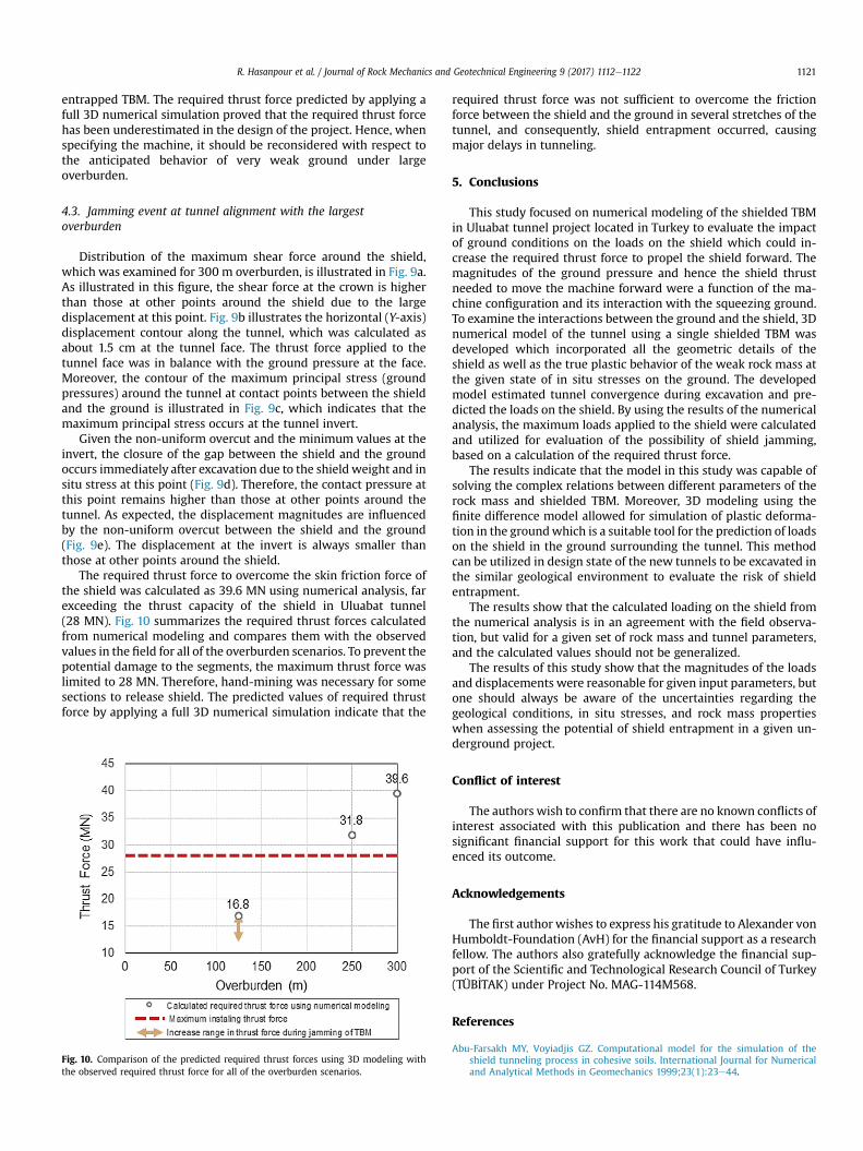
The required thrust force to overcome the skin friction force ofthe shield was calculated as 39.6 MN using numerical analysis, farexceeding the thrust capacity of the shield in Uluabat tunnel(28 MN). Fig. 10 summarizes the required thrust forces calculatedfrom numerical modeling and compares them with the observedvalues in the field for all of the overburden scenarios. To prevent thepotential damage to the segments, the maximum thrust force waslimited to 28 MN. Therefore, hand-mining was necessary for somesections to release shield. The predicted values of required thrustforce by applying a full 3D numerical simulation indicate that the
Fig. 10. Comparison of the predicted required thrust forces using 3D modeling withthe observed required thrust force for all of the overburden scenarios.
required thrust force was not sufficient to overcome the frictionforce between the shield and the ground in several stretches of thetunnel, and consequently, shield entrapment occurred, causingmajor delays in tunneling.
5. Conclusions
This study focused on numerical modeling of the shielded TBMin Uluabat tunnel project located in Turkey to evaluate the impactof ground conditions on the loads on the shield which could in-crease the required thrust force to propel the shield forward. Themagnitudes of the ground pressure and hence the shield thrustneeded to move the machine forward were a function of the ma-chine configuration and its interaction with the squeezing ground.To examine the interactions between the ground and the shield, 3Dnumerical model of the tunnel using a single shielded TBM wasdeveloped which incorporated all the geometric details of theshield as well as the true plastic behavior of the weak rock mass atthe given state of in situ stresses on the ground. The developedmodel estimated tunnel convergence during excavation and pre-dicted the loads on the shield. By using the results of the numericalanalysis, the maximum loads applied to the shield were calculatedand utilized for evaluation of the possibility of shield jamming,based on a calculation of the required thrust force.
The results indicate that the model in this study was capable ofsolving the complex relations between different parameters of therock mass and shielded TBM. Moreover, 3D modeling using thefinite difference model allowed for simulation of plastic deforma-tion in the groundwhich is a suitable tool for the prediction of loadson the shield in the ground surrounding the tunnel. This methodcan be utilized in design state of the new tunnels to be excavated inthe similar geological environment to evaluate the risk of shieldentrapment.
The results show that the calculated loading on the shield fromthe numerical analysis is in an agreement with the field observa-tion, but valid for a given set of rock mass and tunnel parameters,and the calculated values should not be generalized.
The results of this study show that the magnitudes of the loadsand displacements were reasonable for given input parameters, butone should always be aware of the uncertainties regarding thegeological conditions, in situ stresses, and rock mass propertieswhen assessing the potential of shield entrapment in a given un-derground project.
Conflict of interest
The authors wish to confirm that there are no known conflicts ofinterest associated with this publication and there has been nosignificant financial support for this work that could have influ-enced its outcome.
Acknowledgements
The first author wishes to express his gratitude to Alexander vonHumboldt-Foundation (AvH) for the financial support as a researchfellow. The authors also gratefully acknowledge the financial sup-port of the Scientific and Technological Research Council of Turkey(TÜB_ITAK) under Project No. MAG-114M568.
References
Abu-Farsakh MY, Voyiadjis GZ. Computational model for the simulation of theshield tunneling process in cohesive soils. International Journal for Numericaland Analytical Methods in Geomechanics 1999;23(1):23e44.

R. Hasanpour et al. / Journal of Rock Mechanics and Geotechnical Engineering 9 (2017) 1112e11221122
Amberg F. Numerical simulations of tunnelling in soft rock under water pressure.In: ECCOMAS Thematic Conference on Computational Methods in Tunnelling,EURO: TUN 2009. Bochum, Germany: Aedificatio Publishers; 2009. p. 353e60.
Augarde CE, Burd HJ. Three-dimensional finite element analysis of lined tunnels.International Journal for Numerical and Analytical Methods in Geomechanics2001;25(3):243e62.
Bernat S, Cambou B. Soilestructure interaction in shield tunnelling in soft soil.Computers and Geotechnics 1998;22(3e4):221e42.
Bilgin N, Algan M. The performance of a TBM in a squeezing ground at Uluabat,Turkey. Tunnelling and Underground Space Technology 2012;32:58e65.
Cantieni L, Anagnostou G. The effect of the stress path on squeezing behaviour intunnelling. Rock Mechanics and Rock Engineering 2009;42(2):289e318.
Chakeri H, Hasanpour R, Hindistan MA, Ünver B. Analysis of interaction betweentunnels in soft ground by 3D numerical modeling. Bulletin of Engineering Ge-ology and Environment 2011;70(3):439e48.
Dias D, Kastner R, Maghazi M. Three dimensional simulation of slurry shieldtunnelling. In: Kusakabe O, Fujita K, Miyazaki Y, editors. Geotechnical aspects ofunderground construction in soft ground. Rotterdam: A.A. Balkema; 2000.p. 351e6.
Einstein HH, Bobet A. Mechanized tunnelling in squeezing rock-from basic thoughtsto continuous tunneling. In: Golser J, Hinkel WJ, Schubert W, editors. Tunnelsfor people, Proceedings of the 23rd ITA Assembly. Vienna, Austria: A.A. Bal-kema; 1997. p. 619e32.
Farrokh E, Rostami J. Correlation of tunnel convergence with TBM operational pa-rameters and chip size in the Ghomroud tunnel, Iran. Tunnelling and Under-ground Space Technology 2008;23(6):700e10.
Finno RJ, Clough GW. Evaluation of soil response to EPB shield tunneling. Journal ofGeotechnical Engineering 1985;111(2):155e73.
Gehring KH. Design criteria for TBM’s with respect to real rock pressure. In: Tunnelboring machines e trends in design and construction of mechanized tunnelling,International Lecture Series TBM Tunnelling Trends, Hagenberg. Rotterdam:A.A. Balkema; 1996. p. 43e53.
Graziani A, Ribacchi R, Capata A. 3D-modelling of TBM excavation in squeezing rockmasses. In: Brenner Basistunnel und Zulaufstrecken, Internationales Sympo-sium BBT 2007. Innsbruck, Austria: Innsbruck University Press; 2007. p. 143e51.
Hasanpour R, Chakeri H, Özcelik Y, Denek H. Evaluation of surface settlements inthe Istanbul metro in terms of analytical, numerical and direct measurements.Bulletin of Engineering Geology and Environment 2012;71(3):499e510.
Hasanpour R, Rostami J, Barla G. Impact of advance rate on entrapment risk of adouble-shielded TBM in squeezing grounds. Rock Mechanics and Rock Engi-neering 2015;48(3):1115e30.
Hasanpour R, Rostami J, Özcelik Y. Impact of overcut on interaction between shieldand ground in the tunneling with a double-shield TBM. Rock Mechanics andRock Engineering 2016;49(5):2015e22.
Hasanpour R, Rostami J, Ünver B. 3D finite difference model for simulation ofdouble shield TBM tunneling in squeezing grounds. Tunnelling and Under-ground Space Technology 2014;40:109e26.
Hasanpour R. Advance numerical simulation of tunneling by using a double shieldTBM. Computers and Geotechnics 2014;57:37e52.
Itasca FLAC3D (fast Lagrangian analysis of continua in 3 dimensions) user’s guide.Minneapolis, USA: Itasca Consulting Group; 2012.
Kasper T, Meschke GA. 3D finite element simulation model for TBM tunnelling insoft ground. International Journal for Numerical and Analytical Methods inGeomechanics 2004;28(14):1441e60.
Kasper T, Meschke G. A numerical study of the effect of soil and grout materialproperties and cover depth in shield tunnelling. Computers and Geotechnics2006a;33(4e5):234e47.
Kasper T, Meschke G. On the influence of face pressure, grouting pressure and TBMdesign in soft ground tunnelling. Tunnelling and Underground Space Tech-nology 2006b;21(2):160e71.
Komiya K, Soga K, Akagi H, Hagiwara T, Bolton MD. Finite element modelling ofexcavation and advancement processes of a shield tunnelling machine. Soilsand Foundations 1999;39(3):37e52.
Lambrughi A, Medina Rodríguez L, Castellanza R. Development and validation of a3D numerical model for TBM-EPB mechanised excavations. Computers andGeotechnics 2012;40:97e113.
Lee KM, Rowe RK. An analysis of three-dimensional ground movements: theThunder Bay tunnel. Canadian Geotechnical Journal 1991;28(1):25e45.
Lombardi G, Panciera A. Problems with TBM and linings in squeezing ground.Tunnels and Tunnelling International 1997;29:54e6.
Mansour MAM. Three-dimensional numerical modelling of hydroshield tunnelling.PhD Thesis. University of Innsbruck; 1996.
Melis M, Medina L, Rodríguez JM. Prediction and analysis of subsidence induced byshield tunnelling in the Madrid metro extension. Canadian Geotechnical Journal2002;39:1273e87.
Mroueh H, Shahrour I. A simplified 3D model for tunnel construction using tunnelboring machines. Tunnelling and Underground Space Technology 2008;23(1):38e45.
Ramoni M, Anagnostou G. Numerical analysis of the development of squeezingpressure during TBM standstills. In: Olalla C, Grossmann N, Sousa LR, editors.The Second Half Century of Rock Mechanics, 11th Congress of the InternationalSociety for Rock Mechanics (ISRM). Lisbon, London: Taylor & Francis Group;2007. p. 963e6.
Ramoni M, Anagnostou G. Thrust force requirements for TBMs in squeezing ground.Tunnelling and Underground Space Technology 2010;25(4):433e55.
Schmitt JA. Spannungsverformungsverhalten des Gebirges beim Vortrieb mitTunnelbohrmaschinen mit Schild. PhD Thesis. Institut für Grundbau und Bod-enmechanik, Technische Universität Braunschweig; 2009 (in Germany).
Sterpi D, Gioda G. Ground pressure and convergence for TBM driven tunnels invisco-plastic rocks. In: ECCOMAS Thematic Conference on ComputationalMethods in Tunnelling, EURO: TUN 2007. Vienna, Austria: Vienna University ofTechnology; 2007. p. 89e95.
van Dijk B, Kaalberg FJ. 3D geotechnical model for the North/Southline in Amster-dam. In: Cividini A, editor. Application of numerical methods to geotechnicalproblems. Vienna, Austria: Springer; 1998. p. 739e50.
Wittke W, Wittke-Gattermann P, Wittke-Schmitt B. TBM-heading in rock, design ofthe shield mantle. In: ECCOMAS Thematic Conference on ComputationalMethods in Tunnelling, EURO: TUN 2007. Vienna, Austria: Vienna University ofTechnology; 2007. p. 98.
Zhao K, Janutolo M, Barla G. A completely 3D model for the simulation of mecha-nized tunnel excavation. Rock Mechanics and Rock Engineering 2012;45(4):475e97.
Dr. Rohola Hasanpour is a postdoctoral researcher inInstitute for Tunneling and Construction Management atRuhr-University Bochum. He received his PhD in Rock Me-chanics and Tunneling Engineering from Hacettepe Uni-versity in 2013. His PhD Thesis focused on applicabilityof shielded tunnel boring machines (TBMs) in squeezingground conditions. He has published over 15 peerreviewed journal publications, more than 20 papers in in-ternational conferences and many technical reports. Heworked several years as a project engineer in the field oftunneling and underground construction and is familiarwith the practical aspect of rock mechanics and rock engi-neering. His research interests include computationalmodeling in geomechanics, time-dependent simulation in
underground constructions and rock fracture mechanics.