EWM-SS-DAD - grieger-automation.com eng...Housing dimensions - EWM-SS-DAD - EWM-BUS-DD mm 120 x...
14
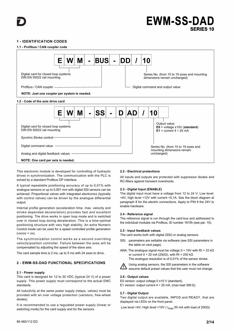
89 460/112 ED EWM-SS-DAD CARD FOR AXIS SYNCHRONIZATION CONTROL FOR SYSTEMS FROM 2 TO 24 AXES WITH PROFIBUS/CAN COMMUNICATION INTERFACE SERIES 10 OPERATING PRINCIPLE 89 460/112 ED RAIL MOUNTING TYPE: DIN EN 50022 — This card has been developed as axes controller and it is connected to the other cards via Canbus. This bus line has to be coupled with a PLC interface Profibus DP, the EWM-BUS- DD/10 (to be ordered separately). — The EWM-SS-DAD synchronizes the axes with a high accuracy. The position accuracy is reached using a digital sensor with SSI interface to measure the position. The card can drive only an hydraulic axis per card, so a EWM-SS-DAD per axis is needed. — The synchronization controller correct the speed of the slave axis. Positioning failures during the movement will increase or reduce the slave axis velocity, so the synchronization failure will be compensated. — The card use the RS232C interface, and is easily settable via notebook, using the software kit (EWMPC). Power supply V DC 12 ÷ 30 ripple included - external fuse 1,0 A Current consumption mA < 200 + sensor power consumption Command value via Profibus DP - ID number 1810h Speed input value via Profibus DP - ID number 1810h Feedback value V mA SSI 0 ÷ 10 (R I = 33 kΩ) 4 ÷ 20 (R I = 250 Ω) digital sensor with any SSI interface Output value: - E0 version - E1 version V mA ±10 (max load 5 mA) 4 ÷ 20 (max load 390 Ω ) Position accuracy ± 2 bits of digital sensor resolution Interface RS 232 C Electromagnetic compatibility (EMC): according to 2004/108/CE standards Emissions EN 61000-6-3 Immunity EN 61000-6-2 Housing material thermoplastic polyamide PA6.6 combustibility class V0 (UL94) Housing dimensions - EWM-SS-DAD - EWM-BUS-DD mm 120 x 99(h) x 46(w) 120 x 99(h) x 23(w) Connector 4x4 poles screw terminals - PE direct via DIN rail Operating temperature range °C -20 / +60 Protection degree IP 20 TECHNICAL CHARACTERISTICS 1/14 1 2
Transcript of EWM-SS-DAD - grieger-automation.com eng...Housing dimensions - EWM-SS-DAD - EWM-BUS-DD mm 120 x...
89 460/112 ED
EWM-SS-DADCARD FOR AXIS
SYNCHRONIZATION CONTROLFOR SYSTEMS FROM 2 TO 24
AXES WITH PROFIBUS/CANCOMMUNICATION INTERFACE
SERIES 10
OPERATING PRINCIPLE
89 460/112 ED
RAIL MOUNTING TYPE:
DIN EN 50022
— This card has been developed as axes controller and it isconnected to the other cards via Canbus. This bus line has tobe coupled with a PLC interface Profibus DP, the EWM-BUS-DD/10 (to be ordered separately).
— The EWM-SS-DAD synchronizes the axes with a highaccuracy. The position accuracy is reached using a digitalsensor with SSI interface to measure the position. The cardcan drive only an hydraulic axis per card, so a EWM-SS-DADper axis is needed.
— The synchronization controller correct the speed of the slaveaxis. Positioning failures during the movement will increase orreduce the slave axis velocity, so the synchronization failurewill be compensated.
— The card use the RS232C interface, and is easily settable vianotebook, using the software kit (EWMPC).
Power supply V DC 12 ÷ 30 ripple included - external fuse 1,0 A
Current consumption mA < 200 + sensor power consumption
Command value via Profibus DP - ID number 1810h
Speed input value via Profibus DP - ID number 1810h
Feedback valueV
mASSI
0 ÷ 10 (RI = 33 kΩ)4 ÷ 20 (RI = 250 Ω)
digital sensor with any SSI interface
Output value: - E0 version- E1 version
VmA
±10 (max load 5 mA)4 ÷ 20 (max load 390 Ω )
Position accuracy ± 2 bits of digital sensor resolution
Interface RS 232 C
Electromagnetic compatibility (EMC):according to 2004/108/CE standards
Emissions EN 61000-6-3Immunity EN 61000-6-2
Housing materialthermoplastic polyamide PA6.6combustibility class V0 (UL94)
Housing dimensions - EWM-SS-DAD- EWM-BUS-DD
mm120 x 99(h) x 46(w)120 x 99(h) x 23(w)
Connector 4x4 poles screw terminals - PE direct via DIN rail
Operating temperature range °C -20 / +60
Protection degree IP 20
TECHNICAL CHARACTERISTICS
1/14
1 2
89 460/112 ED 2/14
EWM-SS-DADSERIES 10
EWM-SS-DADSERIES 10
2.2 - Electrical protections
All inputs and outputs are protected with suppressor diodes andRC-filters against transient overshoots.
2.3 - Digital Input (ENABLE)
The digital input must have a voltage from 12 to 24 V; Low level:<4V, high level >12V with current <0,1A. See the block diagram atparagraph 8 for the electric connections. Apply to PIN 8 the 24V toenable hardware.
2.4 - Reference signal
The reference signal is run through the card-bus and addressed tothe individual modules via Profibus, ID number 1810h (see par. 10).
2.5 - Input feedback values
The card works both with digital (SSI) or analog sensors.
SSI: parameters are settable via software (see SSI parameters in the table on next page).
ANA: The analogue signal must be voltage 0 ÷ 10V with RI = 33 kΩor current 4 ÷ 20 mA (250Ω), with RI = 250 kΩThe analogue resolution is of 0,01% of the sensor stroke.
Using analog sensors, the SSI parameters in the software assume default preset values that the user must not change.
2.6 - Output values
E0 version: output voltage 0 ±10 V (standard). E1 version: output current 4 ÷ 20 mA. (max load 390 Ω)
2.7 - Digital Output
Two digital output are available, INPOS and READY, that aredisplayed via LEDs on the front panel. .
Low level <4V; High level >10V ( Imax 50 mA with load of 200Ω)
This electronic module is developed for controlling of hydraulicdrives in synchronization. The communication with the PLC issolved by a standard Profibus DP interface.
A typical repeatable positioning accuracy of up to 0,01% withanalogue sensors or up to 0,001 mm with digital SSI sensors can beachieved. Proportional valves with integrated electronics (typicallywith control valves) can be driven by the analogue differentialoutput.
Internal profile generation (acceleration time, max. velocity andstroke depended deceleration) provides fast and excellentpositioning. The drive works in open loop mode and is switchedover in closed loop during deceleration. This is a time-optimalpositioning structure with very high stability. An extra NumericControl mode can be used for a speed controlled profile generation(VMODE = ON).
The synchronization control works as a second overridingvelocity/position controller. Failure between the axes will becompensated by adjusting the speed of the slave axis.
The card sample time is 2 ms, up to 5 ms with 24 axes to drive.
2 - EWM-SS-DAD FUNCTIONAL SPECIFICATIONS
2.1 - Power supply
This card is designed for 12 to 30 VDC (typical 24 V) of a powersupply. This power supply must correspond to the actual EMCstandards.
All inductivity at the same power supply (relays, valves) must beprovided with an over voltage protection (varistors, free-wheeldiodes).
It is recommended to use a regulated power supply (linear orswitching mode) for the card supply and for the sensors.
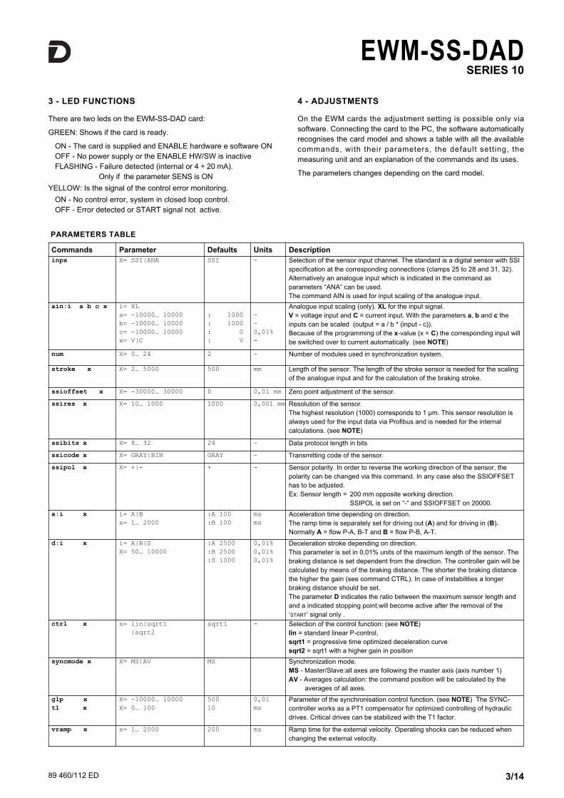
1 - IDENTIFICATION CODES
Digital command value
Analog and digital feedback values
Series No. (from 10 to 19 sizes andmounting dimensions remainunchanged)
Digital card for closed loop systemsDIN EN 50022 rail mounting
Synchro Stroke control
E W M - SS - D AD / 10
Output value:E0 = voltage ±10V (standard)E1 = current 4 ÷ 20 mA
Digital command and output value
Series No. (from 10 to 19 sizes and mountingdimensions remain unchanged)
Digital card for closed loop systemsDIN EN 50022 rail mounting
Profibus / CAN coupler
E W M - BUS - DD / 10
1.1 - Profibus / CAN coupler code
1.2 - Code of the axis drive card
NOTE: Just one coupler per system is needed.
NOTE: One card per axis is needed.
89 460/112 ED 3/14
EWM-SS-DADSERIES 10
Commands Parameter Defaults Units Description
inpx X= SSI|ANA SSI - Selection of the sensor input channel. The standard is a digital sensor with SSIspecification at the corresponding connections (clamps 25 to 28 and 31, 32).Alternatively an analogue input which is indicated in the command asparameters “ANA” can be used. The command AIN is used for input scaling of the analogue input.
ain:i a b c x i= XLa= -10000… 10000b= -10000… 10000c= -10000… 10000x= V|C
: 1000: 1000: 0: V
--0,01%-
Analogue input scaling (only). XL for the input signal. V = voltage input and C = current input. With the parameters a, b and c theinputs can be scaled (output = a / b * (input - c)).Because of the programming of the x-value (x = C) the corresponding input willbe switched over to current automatically. (see NOTE)
num X= 0… 24 2 - Number of modules used in synchronization system.
stroke x X= 2… 5000 500 mm Length of the sensor. The length of the stroke sensor is needed for the scalingof the analogue input and for the calculation of the braking stroke.
ssioffset x X= -30000… 30000 0 0,01 mm Zero point adjustment of the sensor.
ssires x X= 10… 1000 1000 0,001 mm Resolution of the sensor. The highest resolution (1000) corresponds to 1 μm. This sensor resolution isalways used for the input data via Profibus and is needed for the internalcalculations. (see NOTE)
ssibits x X= 8… 32 24 - Data protocol length in bits
ssicode x X= GRAY|BIN GRAY - Transmitting code of the sensor.
ssipol x X= +|- + - Sensor polarity. In order to reverse the working direction of the sensor, thepolarity can be changed via this command. In any case also the SSIOFFSEThas to be adjusted. Ex: Sensor length = 200 mm opposite working direction.
SSIPOL is set on “-“ and SSIOFFSET on 20000.
a:i x i= A|Bx= 1… 2000
:A 100:B 100
msms
Acceleration time depending on direction. The ramp time is separately set for driving out (A) and for driving in (B).Normally A = flow P-A, B-T and B = flow P-B, A-T.
d:i x i= A|B|SX= 50… 10000
:A 2500:B 2500:S 1000
0,01%0,01%0,01%
Deceleration stroke depending on direction. This parameter is set in 0,01% units of the maximum length of the sensor. Thebraking distance is set dependent from the direction. The controller gain will becalculated by means of the braking distance. The shorter the braking distancethe higher the gain (see command CTRL). In case of instabilities a longerbraking distance should be set. The parameter D indicates the ratio between the maximum sensor length andand a indicated stopping point;will become active after the removal of the‘START’ signal only .
ctrl x x= lin|sqrt1|sqrt2
sqrt1 - Selection of the control function: (see NOTE)lin = standard linear P-control, sqrt1 = progressive time optimized deceleration curvesqrt2 = sqrt1 with a higher gain in position
syncmode x X= MS|AV MS Synchronization mode. MS - Master/Slave:all axes are following the master axis (axis number 1)AV - Averages calculation: the command position will be calculated by the
averages of all axes.
glp xt1 x
X= -10000… 10000X= 0… 100
50010
0,01ms
Parameter of the synchronisation control function. (see NOTE) The SYNC-controller works as a PT1 compensator for optimized controlling of hydraulicdrives. Critical drives can be stabilized with the T1 factor.
vramp x x= 1… 2000 200 ms Ramp time for the external velocity. Operating shocks can be reduced whenchanging the external velocity.
PARAMETERS TABLE
3 - LED FUNCTIONS
There are two leds on the EWM-SS-DAD card:
GREEN: Shows if the card is ready.
ON - The card is supplied and ENABLE hardware e software ON OFF - No power supply or the ENABLE HW/SW is inactiveFLASHING - Failure detected (internal or 4 ÷ 20 mA).
Only if the parameter SENS is ON
YELLOW: Is the signal of the control error monitoring.
ON - No control error, system in closed loop control. OFF - Error detected or START signal not active.
4 - ADJUSTMENTS
On the EWM cards the adjustment setting is possible only viasoftware. Connecting the card to the PC, the software automaticallyrecognises the card model and shows a table with all the availablecommands, with their parameters, the default sett ing, themeasuring unit and an explanation of the commands and its uses.
The parameters changes depending on the card model.

89 460/112 ED 4/14
EWM-SS-DADSERIES 10
vmode x x= on|off off - Activation of the NC-generator. In OFF state the stroke depended deceleration is active; the velocity presetlimits the output signal.In ON state a profile generator generates the positioning demand value and theaxis drives to the target position with the defined velocity. The stroke time is defined by the parameter VEL.
vel x X= 1… 20000 50 mm/s Internal maximum velocity preset.This parameter is only active in case of VMODE = ON.
min:i x i= A|Bx= 0… 5000
:A 0:B 0
0,01%0,01%
Deadband compensation of positive overlapped proportional valves. Good adjustment will increase positioning accuracy
max:i x i= A|BX= 5000… 10000
:A 10000:B 10000
0,01%0,01%
Maximum output signal. Adapt the control range to maximum flow range.
trigger x X= 0… 2000 200 0,01% Point to activate the deadband compensation (min). (see NOTE) Also useful for reduced sensitivity in position with control valves.
inpos xglerror x
X= 0… 5000x= 0… 5000
200200
0,01mm0,01mm
Synchronization error.This parameter is entered in 0,01 mm units.The INPOS command defines the window when the INPOS message isindicated. The positioning process is not influenced by this message. Thecontroller remains active.In NC-mode ( VMODE = ON) this message has to be interpreted as followingerror control. With the GLERROR value the synchronization error window isdefined.
offset x x= -2000… 2000 0 0,01% Zero point adjustment. The corresponding OFFSET will be added to the controlerror (demand value - actual value + offset). With this parameter the zero pointfailure can be compensated.
pol x x= +|- + - Output polarity. All A and B adjustments depend on the output polarity. The right polarity should be defined first.
sens x x= on|off on - The sensor monitoring can be activated (with 4… 20 mA sensors).
save - - - Storing the programmed parameter in E²PROM.
loadback - - - Reloading the parameter from E²PROM in working RAM
help - - - Listing of all available commands.
para - - - Actual parameter list with all programmed values.
copy - - - Transfer of the parameters into all other modules at the node CAN. The parameters are stored in the EEPROM.Caution: All up to now adjusted values are overwritten in all modules. This command is carried out usually during the first basic installation.
st - - - Internal status. Monitoring of the control and status word (see par. 10).Command available via software only.
wlxlxwkxkxwvux:i
Demand valueActual valueControl deviationSync positionSync errorVelocityActuator signalIndexed axes process
- 0,01 mm The process data can be read out via software. They show the actual and command values
default - - - Preset values will be set.
NOTE about the AIN command: This command is for analogue sensor only.
With this command each input can be scaled individually. For the scaling function the following linear equation is taken: output signal = a / b *(input signal - c).
At first the offset (c) will be subtracted (in 0,01% units) from the input signal, then the signal will be multiplied with factor a / b. a and b shouldalways be positive. With these both factors every floating-point value can be simulated (for example: 1.345 = 1345 / 1000).
With the x parameter value the internal measuring resistance for the current measuring (4… 20 mA) will be activated (V for voltages input andC for current input). ATTENTION: This resistor is never activated at the k input.
AIN:X a b c x
i with voltage: AIN:i 1000 1000 0 Vi with current: AIN:i 1250 1000 2000 C

89 460/112 ED 5/14
EWM-SS-DADSERIES 10
braking stroke
velocity
stroke
NOTE about the CTRL command: This command controls the braking characteristic ofthe hydraulic axis. With positive overlapped proportional valves one of both SQRT brakingcharacteristics should be used because of the linearization of the non-linear flow curvetypical of these valves If zero overlapped proportional valves (control valves) are used,you can choose between LIN and SQRT1 according to the application. The progressivegain characteristic of SQRT1 has the better positioning accuracy.
According to the application there is maybe a longer braking distance, so that the totalstroke time will be longer.
LIN: Linear braking characteristics (control gain corresponds to: 10000 / d:i).
SQRT*: Root function for the calculation for the braking curve. SQRT1: with small control error. control gain corresponds to 30000 / d:i ; SQRT2: control gain corresponds to 50000 / d:i
NOTE about the SSIRES command: the standard of measurement is defined as increment/mm (inkr/mm). The maximum available resolutionis equal to 1 µm that corresponds to a value 1000.
Example: A sensor with resolution 5µm has a resolution (0.005 mm) 5 times lower than the maximum set. The SSIRES value is calculated as follows: 1000 (full scale ink) / n (sensor resolution in µm) = 1000 / 5 = 200
NOTE about the TRIGGER command: With this command, the output signal is adjustedto the valve characteristics. The positioning controllers have a double-gain characteristiccurve instead of a typical overlapped jump. The advantage is a better and more stabilepositioning behaviour. With this compensation, non-linear volume flow characteristiccurves can be adjusted too.
If there exist also possibilities for adjustments at the valve or at the valve electronics, it hasto be guaranteed, that the adjustment has to be carried out at the power amplifier or at thepositioning module. If the MIN value is set too high, it influences the minimal velocity,which cannot be adjusted any longer. In extreme case this causes to an oscillating aroundthe closed loop controlled position.
NOTE about the GLP and T1 command: Both controllers (sync and positioning) areworking parallel. The higher the sync-gain the lower must be the gain of the positioningcontroller. A time constant value (T1) can be used to damp the sync-controller for betterstability.
Simplified control structure:
89 460/112 ED 6/14
EWM-SS-DADSERIES 10
5 - INSTALLATION
The card is designed for rail mounting type DIN EN 50022.
The wiring connections are on the terminal strip located on thebottom of the electronic control unit. It is recommended to use cablesections of 0.75 mm2, up to 20 m length and of 1.00 mm2 up to 40mlength, for power supply and solenoid connections. For otherconnections it is recommended to use cables with a screenedsheath connected to earth only on the card side.
NOTE: To observe EMC requirements it is important that the controlunit electrical connection is in strict compliance with the wiringdiagram. As a general rule, the valve and the electronic unitconnection wires must be kept as far as possible from interferencesources (e.g. power wires, electric motors, inverters and electricalswitches).
In environments that are crit ical from the electromagneticinterference point of view, a complete protection of the connectionwires can be requested.
A typical screened Profibus plug (D-Sub 9pol with switchabletermination) is mandatory. Also the Profibus cable must bescreened.
Every Profibus segment must be provided with an active bustermination at the beginning and at the end. The termination isalready integrated in all common Profibus plugs and can beactivated by DIL switches.
For the installation of the EWM-BUS-DD only a few steps arenecessary (CAN-side).
Electric connection: the CAN Bus of the modules is wired with theCAN Bus of the coupler.
EWM-SS-DAD: PIN 23 at PIN EWM-BUS-DD 1EWM-SS-DAD: PIN 22 at PIN EWM-BUS-DD 4EWM-SS-DAD: PIN 21 at PIN EWM-BUS-DD 3
Power supply: PIN 5 and PIN 6 = 24 VPIN 7 and PIN 8 = 0 V
5.1 - CAN interface
The CAN interface is wired on all modules in parallel. Theterminating resistors have to be activated in the EWM-SS-DAD atthe first and last module.
The addressing of the EWM-SS-DAD about the DIL switches mustbegin with one. The first module has a master functionality andtakes over the communication with the interface converterEWM-BUS-DD. The DIL-switch is inside the unit on the interfaceboard opposite of the main board. Position and switch position aremarked.
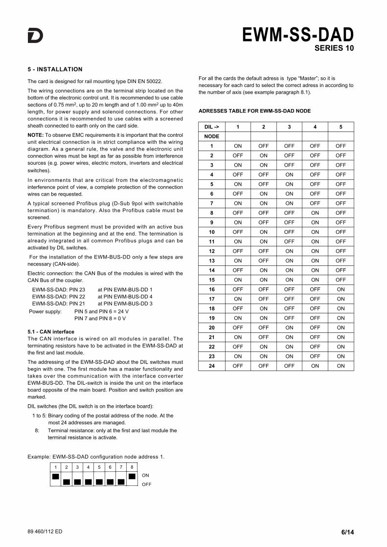
DIL switches (the DIL switch is on the interface board):
1 to 5: Binary coding of the postal address of the node. At the most 24 addresses are managed.
8: Terminal resistance: only at the first and last module the terminal resistance is activate.
Example: EWM-SS-DAD configuration node address 1.
ON
OFF
For all the cards the default adress is type “Master”; so it isnecessary for each card to select the correct adress in according tothe number of axis (see example paragraph 8.1).
ADRESSES TABLE FOR EWM-SS-DAD NODE
1 2 3 4 5 6 7 8
DIL -> 1 2 3 4 5
NODE
1 ON OFF OFF OFF OFF
2 OFF ON OFF OFF OFF
3 ON ON OFF OFF OFF
4 OFF OFF ON OFF OFF
5 ON OFF ON OFF OFF
6 OFF ON ON OFF OFF
7 ON ON ON OFF OFF
8 OFF OFF OFF ON OFF
9 ON OFF OFF ON OFF
10 OFF ON OFF ON OFF
11 ON ON OFF ON OFF
12 OFF OFF ON ON OFF
13 ON OFF ON ON OFF
14 OFF ON ON ON OFF
15 ON ON ON ON OFF
16 OFF OFF OFF OFF ON
17 ON OFF OFF OFF ON
18 OFF ON OFF OFF ON
19 ON ON OFF OFF ON
20 OFF OFF ON OFF ON
21 ON OFF ON OFF ON
22 OFF ON ON OFF ON
23 ON ON ON OFF ON
24 OFF OFF OFF ON ON

89 460/112 ED 7/14
EWM-SS-DADSERIES 10
pin Signal name Function
1-2-7-9 not used -
3 RxD/TxD-P (B-Line) Receive/Send P data
4 CNTR-P/RTS Request to Send
5 DGND Data ground
6 VP +5 V DC for external bustermination
8 RxD/TxD-N (A-Line) Receive/Send N data
PROFIBUS PORT WIRING AND LINKING CONFIGURATION6 - PROFIBUS/CANbus card EWM-BUS-DD
The module supports all baud rates from 9,6 kbit/s up to 12000kbit/s with auto detection of the baud rate. The functionality isdefined in IEC 61158. The Profibus address can be programmed bya terminal program, EWMPC/10 or online via the Profibus.
The reference values are preset over the digital Profibus / CAN-Busthat worked with full internal resolution. The position resolutioncorresponds to the sensor resolution.
TIn the EWM-BUS-DD the presetting is to be maintained for theCAN-Bus (address 2 and 1 MBd).
DIL Switches configuration for module EWM-BUS-DD:
ON
OFF
DIL Switches is inside the module and it gives the possibility to setaddress and data transmission speed.
tables below show the meaning of DIL Switches:
6.1 - Display
The EWM-BUS-DD has a display that shows the module status:
- everything OK, Profibus and CAN Bus in data exchange1 Error, CAN Bus no data exchange2 Error, Profibus no communication3 Error, Profibus no communication, CAN Bus no data
exchange4 Error, Profibus OK, not connected CAN Bus5 Error, Profibus no communication, not connected CAN Bus6 Error, hardware fault
6.2 - ProfiBUS port
A shielded typical Profibus connector (9-polig), possibly withinternal terminal resistors, must be used .The pre addressing of themodule can be changed only by Profibus (DEFAULT is 3). Thecable is not included.
7 - SOFTWARE KIT EWMPC/10 (code 3898401001)
The software kit comprising a USB cable (2 mt length) to connectthe card to a PC or notebook and the software.
During the identification all information are read out of the moduleand the table input will be automatically generated.
Some functions like baud rate setting, remote control mode, savingof process data for later evaluation are used to speed up theinstallation procedure.
The software is compliant with Microsoft XP® operating systems.
1 2 3 4 5 6 7
DIP-SWITCH
1 2 3 4 5 6 7
CANBUS ADDRESS NODETRANSMISSION
SPEED
TRANSMISSION
SPEED
DIP-SWITCH
6 7
125 Kbaud OFF OFF
250 Kbaud ON OFF
500 Kbaud OFF ON
1 Mbaud ON ON
89 460/112 ED 8/14
EWM-SS-DADSERIES 10
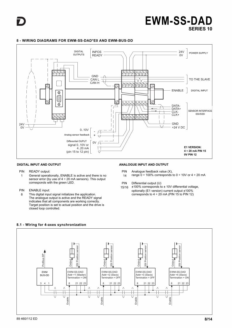
8 - WIRING DIAGRAMS FOR EWM-SS-DAD*E0 AND EWM-BUS-DD
PIN1
READY output: General operationally, ENABLE is active and there is nosensor error (by use of 4 ÷ 20 mA sensors). This outputcorresponds with the green LED.
PIN8
ENABLE input: This digital input signal initializes the application. The analogue output is active and the READY signalindicates that all components are working correctly.Target position is set to actual position and the drive isclosed loop controlled.
PIN14
Analogue feedback value (X), range 0 ÷ 100% corresponds to 0 ÷ 10V or 4 ÷ 20 mA
PIN 15/16
Differential output (U) ±100% corresponds to ± 10V differential voltage, optionally (E1 version) current output ±100%corresponds to 4 ÷ 20 mA (PIN 15 to PIN 12)
DIGITAL INPUT AND OUTPUT ANALOGUE INPUT AND OUTPUT
E1 VERSION:
4 ÷ 20 mA PIN 15
0V PIN 12
8.1 - Wiring for 4-axes synchronization
EWMBUS-DD
DIGITALOUTPUTS
POWER SUPPLY
DIGITAL INPUT
SENSOR INTERFACESSI/SSD
Analog sensor feedback
Differential OUPUT

89 460/112 ED 9/14
EWM-SS-DADSERIES 10
9 - EWM-DD-DAD CARD BLOCK DIAGRAM
OUTPUT SIGNAL - E1 VERSION
89 460/112 ED 10/14
EWM-SS-DADSERIES 10
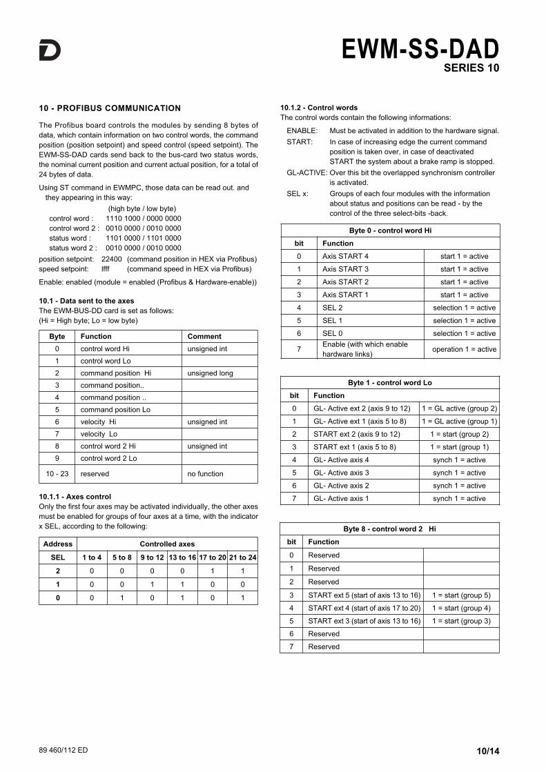
10 - PROFIBUS COMMUNICATION
The Profibus board controls the modules by sending 8 bytes ofdata, which contain information on two control words, the commandposition (position setpoint) and speed control (speed setpoint). TheEWM-SS-DAD cards send back to the bus-card two status words,the nominal current position and current actual position, for a total of24 bytes of data.
Using ST command in EWMPC, those data can be read out. andthey appearing in this way:
(high byte / low byte)control word : 1110 1000 / 0000 0000control word 2 : 0010 0000 / 0010 0000status word : 1101 0000 / 1101 0000status word 2 : 0010 0000 / 0010 0000
position setpoint: 22400 (command position in HEX via Profibus)speed setpoint: lfff (command speed in HEX via Profibus)
Enable: enabled (module = enabled (Profibus & Hardware-enable))
10.1 - Data sent to the axes
The EWM-BUS-DD card is set as follows:(Hi = High byte; Lo = low byte)
10.1.1 - Axes control
Only the first four axes may be activated individually, the other axesmust be enabled for groups of four axes at a time, with the indicatorx SEL, according to the following:
10.1.2 - Control words
The control words contain the following informations:
ENABLE: Must be activated in addition to the hardware signal.
START: In case of increasing edge the current command position is taken over, in case of deactivated START the system about a brake ramp is stopped.
GL-ACTIVE: Over this bit the overlapped synchronism controller is activated.
SEL x: Groups of each four modules with the information about status and positions can be read - by the control of the three select-bits -back.
Byte 1 - control word Lo
bit Function
0 GL- Active ext 2 (axis 9 to 12) 1 = GL active (group 2)
1 GL- Active ext 1 (axis 5 to 8) 1 = GL active (group 1)
2 START ext 2 (axis 9 to 12) 1 = start (group 2)
3 START ext 1 (axis 5 to 8) 1 = start (group 1)
4 GL- Active axis 4 synch 1 = active
5 GL- Active axis 3 synch 1 = active
6 GL- Active axis 2 synch 1 = active
7 GL- Active axis 1 synch 1 = active
Byte 0 - control word Hi
bit Function
0 Axis START 4 start 1 = active
1 Axis START 3 start 1 = active
2 Axis START 2 start 1 = active
3 Axis START 1 start 1 = active
4 SEL 2 selection 1 = active
5 SEL 1 selection 1 = active
6 SEL 0 selection 1 = active
7Enable (with which enablehardware links)
operation 1 = active
Byte Function Comment
0 control word Hi unsigned int
1 control word Lo
2 command position Hi unsigned long
3 command position..
4 command position ..
5 command position Lo
6 velocity Hi unsigned int
7 velocity Lo
8 control word 2 Hi unsigned int
9 control word 2 Lo
10 - 23 reserved no function
Address Controlled axes
SEL 1 to 4 5 to 8 9 to 12 13 to 16 17 to 20 21 to 24
2 0 0 0 0 1 1
1 0 0 1 1 0 0
0 0 1 0 1 0 1
Byte 8 - control word 2 Hi
bit Function
0 Reserved
1 Reserved
2 Reserved
3 START ext 5 (start of axis 13 to 16) 1 = start (group 5)
4 START ext 4 (start of axis 17 to 20) 1 = start (group 4)
5 START ext 3 (start of axis 13 to 16) 1 = start (group 3)
6 Reserved
7 Reserved

10.1.3 - Position setpoint description
Command position: according to the sensor resolution.
Example of calculation of posit ion control for SSI sensor resolution = 5 μm and 100% stroke = 300 mm.
Position setpoint = 150 mm (= 50% stroke)
STROKE • SSIRES = 100% stroke (dec)
300 • 200 = 60.000 (dec) → EA60 (hex)50% di 60.000 = 30.000 (dec) → 7530 (hex)
Example of calculation of position control for ANA sensor with 100%stroke = 300 mm. With analog sensors SSIRES value is preset andunchangeable.
Position setpoint = 150 mm (= 50% stroke)
STROKE • SSIRES = 100% stroke (dec)
300 • 1000 = 300.000 (dec) → 493E0 (hex)50% di 300.000 = 150.000 (dec) → 249F0 (hex)
Byte 9 - control word 2 Lo
bit Function
0 Reserved
1 Reserved
2 Reserved
3 GL- Active ext 5 (axis 21 to 24) 1 = GL active (group 5)
4 GL- Active ext 4 (axis 17 to 20) 1 = GL active (group 4)
5 GL- Active ext 3 (axis 13 to 16) 1 = GL active (group 3)
6 Reserved
7 Reserved
Byte 2 to 5 - command position
bit Function defined by the sensor resolution
from 0 to 7Command positionLo byte
Byte 5
from 8 to 15 Command position Byte 4
from 16 to 23 Command position Byte 3
from 24 to 31Command position Hibyte
Byte 2
Byte 6 and 7 - command velocity
bit Function max value 0x3FFF
from 0 to 7 velocity Lo byte Byte 7
from 8 to 15 velocity Hi byte Byte 6
89 460/112 ED 11/14
EWM-SS-DADSERIES 10
Byte Function Comment
0 status word Hi unsigned int
1 status word Lo
2 control position* Hi unsigned long
3 control position*
4 control position*
5 control position* Lo
6 status word 2 Hi unsigned int
7 status word 2 Lo
8 actual pos. axes 1,5,9,13,17,21 Hi unsigned long
9 actual pos. axes 1,5,9,13,17,21
10 actual pos. axes 1,5,9,13,17,21
11 actual pos. axes 1,5,9,13,17,21 Lo
12 actual pos. axes 2,6,10,14,18,22 Hi unsigned long
13 actual pos. axes 2,6,10,14,18,22
14 actual pos. axes 2,6,10,14,18,22
15 actual pos. axes 2,6,10,14,18,22 Lo
16 actual pos. axes 3,7,11,15,19,23 Hi unsigned long
17 actual pos. axes 3,7,11,15,19,23
18 actual pos. axes 3,7,11,15,19,23
19 actual pos. axes 3,7,11,15,19,23 Lo
20 actual pos. axes 4,8,12,16,20,24 Hi unsigned long
21 actual pos. axes 4,8,12,16,20,24
22 actual pos. axes 4,8,12,16,20,24
23 actual pos. axes 4,8,12,16,20,24 Lo
10.2 - Updating data
The EWM-SS-DAD cards send back to the bus-card two statuswords, the received setpoint command and the current actualposition, totally of 24 bytes of data.
(*) If the average-value control is active (SYNCMODE = AV) theacknowledged value is the calculated position; If the MASTER / SLAVE
(SYNCMODE = MS) is active the acknowledged value will be thecommand position.
Current command position: is interpreted according to modedifferently.
Standard mode : target command position NC-mode : (VMODE = ON) calculated command position
of the generator.
Actual position: according to the sensor resolution.
Position setpoint to be sentwith decimal value 150,000 :
hex 00 02 49 F0
10.1.4 - Speed setpoint description
Command velocity: 0x3fff corresponds to 100 %.
Example: reading the value of stroke 299251:hex 00 04 90 F3
Byte 10
Byte 11
Byte 12
Byte 9
Byte 3
Byte 4
Byte 5
Byte 2

EWM-SS-DADSERIES 10
EWM-SS-DADSERIES 10
EWM-SS-DADSERIES 10
12/1489 460/112 ED
Byte 0 - status word Hi
bit Function
0 INPOS axis 4 1= in position
1 INPOS axis 3 1= in position
2 INPOS axis 2 1= in position
3 INPOS axis 1 1= in position
4 READY axis 4 1= ready
5 READY axis 3 1= ready
6 READY axis 2 1= ready
7 READY axis 1 1= ready
Byte 1 - status word Lo
bit Function
0 COMerror 1 = no error
1 reserved
2 reserved
3 reserved
4 axis GL-Error 4 1 = no error
5 axis GL-Error 3 1 = no error
6 axis GL-Error 2 1 = no error
7 axis GL-Error 1 1 = no error
The status word 2 concerns the messages in the EXTENDED mode.
Byte 6 - status word 2 Hi
bit Function
0 INPOS axis 4, 8, 12, 16, 20, 24 1= no errorCorrespondingsignal indicatorthroughselection bitsSel_0 to Sel_2in the controlword Hi
1 INPOS axis 3, 7, 11, 15, 19, 23
2 INPOS axis 2, 6, 10, 14, 18, 22
3 INPOS axis 1, 5, 9, 13, 17, 21
4 READY axis 4, 8, 12, 16, 20, 24 1= ReadyCorrespondingsignal indicatorthroughselection bitsSel_0 to Sel_2in the controlword Hi
5 READY axis 3, 7, 11, 15, 19, 23
6 READY axis 2, 6, 10, 14, 18, 22
7 READY axis 1, 5, 9, 13, 17, 21
Byte 7 - status word 2 Lo
bit Function
0 reserved
1 reserved
2 reserved
3 reserved
4 GL-Error axis 4, 8, 12, 16, 20, 24 1= no errorCorrespondingsignal indicatorthroughselection bitsSel_0 to Sel_2in the controlword Hi
5 GL-Error axis 3, 7, 11, 15, 19, 23
6 GL-Error axis 2, 6, 10, 14, 18, 22
7 GL-Error axis 1, 5, 9, 13, 17, 21
10.2.1 - Status word descriptions
READY: System is ready.
INPOS: Depending on the mode set, can transmit a positionor, in NC mode, the following error control information.
GL-ERROR: The synchronism error is indicated over this bit by the parameter GLERROR dependently.
SENSOR ERROR: When the sensor monitoring is activated, the READY signal is deactivated with a sensor error.
COMERROR: Communication error on the CAN Bus. This message will be sent only from the module No. 1. if general communication problems are foundor if a module is faulty
Always the hardware enable signal has to be deactivated at asensor error (READY Signal) or when a COM error appear.
89 460/112 ED 13/14
EWM-SS-DADSERIES 10
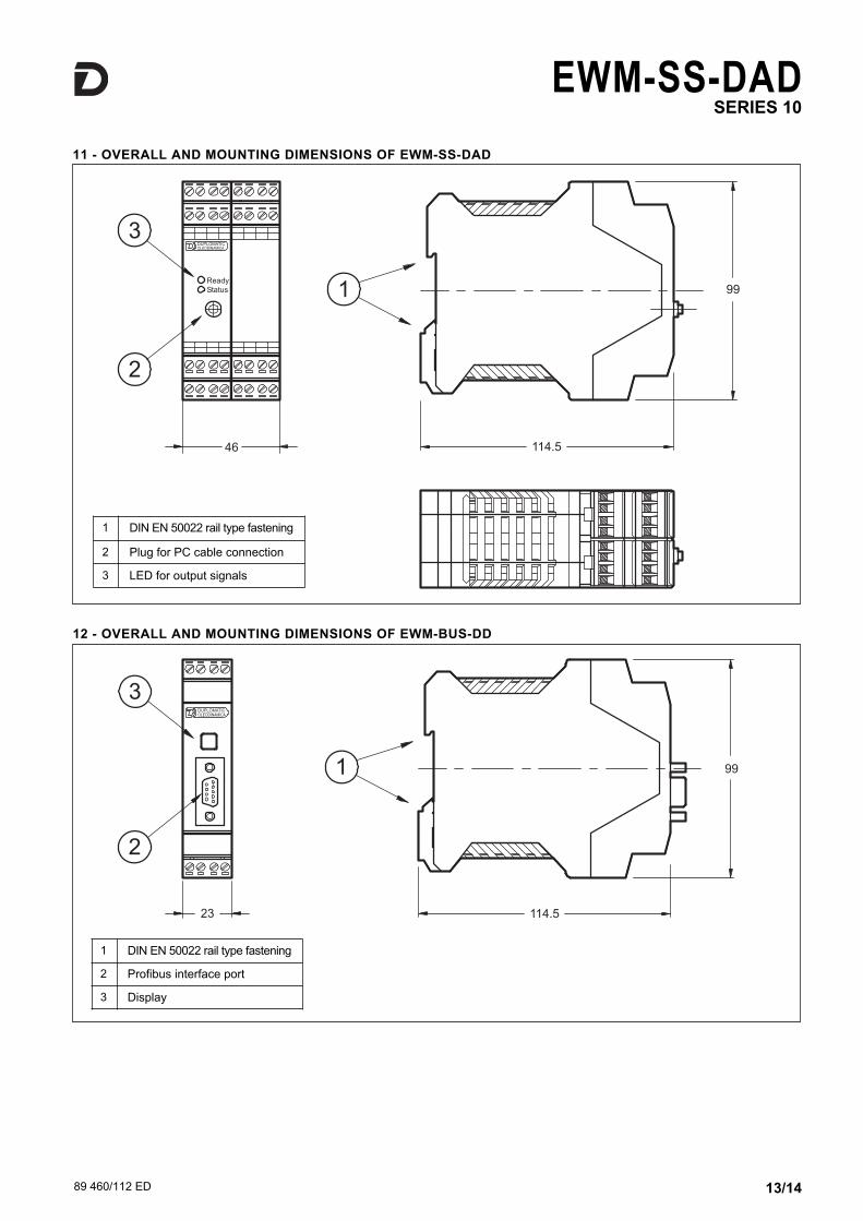
11 - OVERALL AND MOUNTING DIMENSIONS OF EWM-SS-DAD
1 DIN EN 50022 rail type fastening
2 Plug for PC cable connection
3 LED for output signals
12 - OVERALL AND MOUNTING DIMENSIONS OF EWM-BUS-DD
1 DIN EN 50022 rail type fastening
2 Profibus interface port
3 Display

89 460/112 ED 14/14
! "# ! $$$%&'())'*'+,,#-%&'())'
EWM-SS-DADSERIES 10
REPRODUCTION IS FORBIDDEN. THE COMPANY RESERVES THE RIGHT TO APPLY ANY MODIFICATIONS.