
EVS: Head-Up or Head Down? Evaluation of Crew Procedure...
16
1 DGLR-Bericht 2009-02/25 EVS: Head-Up or Head Down? Evaluation of Crew Procedure and Human Factors for Enhanced Vision Systems Bernd R. Korn, Marcus Biella, Helge Lenz & Sven Schmerwitz Abstract Feasibility of an EVS head-down procedure is examined that may provide the same operational benefits under low visibility as the FAA rule on Enhanced Flight Visibility that requires the use of a head-up display (HUD). The main element of the described EVS head-down procedure is the crew procedure within cockpit for flying the approach. The task sharing between Pilot-Flying and Pilot-Not-Flying is arranged such that multiple head-up/head-down transitions can be avoided. The Pilot-Flying is using the head-down display for acquisition of the necessary visual cues in the EVS image. The pilot not flying is monitoring the instruments and looking for the outside visual cues. This paper reports about simulation activities that complete a series of simulation and validation activities carried out in the frame of the European project OPTIMAL. The results support the trend already observed after some preliminary investigations. They suggest that pilots can fly an EVS approach using the proposed EVS head-down display with the same kind of performance (accuracy) as they do with the HUD. There seems to be no loss of situation awareness. Further on, there is not significant trend that the use of the EVS head-down display leads to higher workload compared to the EVS HUD approach. In conclusion, EVS-Head-Down may be as well a feasible option for getting extra operational credit under low visibility conditions. 1 Introduction Enhanced Vision Systems (EVS) are aiming to alleviate restrictions in airspace and airport capacity in low-visibility conditions. EVS relies on weather- penetrating forward-looking sensors that augment the naturally existing visual cues in the environment and provide a real-time image of prominent topographical objects that may be identified by the pilot. The basic idea behind the technology is to allow VMC operations under IMC. Allowing the pilot to “see” under low visibility conditions, EVS increases safety and offers the possibility to increase accessibility and capacity by reducing landing minima or even by reducing separation distances. In the currently existing (FAA, 2004) or
-
Upload
nguyenkiet -
Category
Documents
-
view
213 -
download
0
Transcript of EVS: Head-Up or Head Down? Evaluation of Crew Procedure...

1
DGLR-Bericht 2009-02/25
EVS: Head-Up or Head Down? Evaluation of Crew Procedure and Human Factors for Enhanced Vision
Systems
Bernd R. Korn, Marcus Biella, Helge Lenz & Sven Schmerwitz Abstract Feasibility of an EVS head-down procedure is examined that may provide the same operational benefits under low visibility as the FAA rule on Enhanced Flight Visibility that requires the use of a head-up display (HUD). The main element of the described EVS head-down procedure is the crew procedure within cockpit for flying the approach. The task sharing between Pilot-Flying and Pilot-Not-Flying is arranged such that multiple head-up/head-down transitions can be avoided. The Pilot-Flying is using the head-down display for acquisition of the necessary visual cues in the EVS image. The pilot not flying is monitoring the instruments and looking for the outside visual cues. This paper reports about simulation activities that complete a series of simulation and validation activities carried out in the frame of the European project OPTIMAL. The results support the trend already observed after some preliminary investigations. They suggest that pilots can fly an EVS approach using the proposed EVS head-down display with the same kind of performance (accuracy) as they do with the HUD. There seems to be no loss of situation awareness. Further on, there is not significant trend that the use of the EVS head-down display leads to higher workload compared to the EVS HUD approach. In conclusion, EVS-Head-Down may be as well a feasible option for getting extra operational credit under low visibility conditions.
1 Introduction Enhanced Vision Systems (EVS) are aiming to alleviate restrictions in airspace and airport capacity in low-visibility conditions. EVS relies on weather-penetrating forward-looking sensors that augment the naturally existing visual cues in the environment and provide a real-time image of prominent topographical objects that may be identified by the pilot. The basic idea behind the technology is to allow VMC operations under IMC. Allowing the pilot to “see” under low visibility conditions, EVS increases safety and offers the possibility to increase accessibility and capacity by reducing landing minima or even by reducing separation distances. In the currently existing (FAA, 2004) or
2 B.R. Korn, M. Biella, H. Lenz & S. Schmerwitz
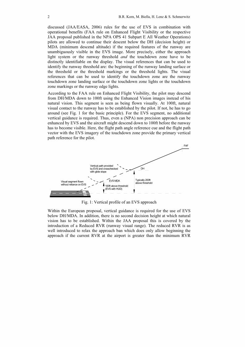
discussed (JAA/EASA, 2006) rules for the use of EVS in combination with operational benefits (FAA rule on Enhanced Flight Visibility or the respective JAA proposal published in the NPA OPS 41 Subpart E All Weather Operations) pilots are allowed to continue their descent below the DH (decision height) or MDA (minimum descend altitude) if the required features of the runway are unambiguously visible in the EVS image. More precisely, either the approach light system or the runway threshold and the touchdown zone have to be distinctly identifiable on the display. The visual references that can be used to identify the runway threshold are: the beginning of the runway landing surface or the threshold or the threshold markings or the threshold lights. The visual references that can be used to identify the touchdown zone are the runway touchdown zone landing surface or the touchdown zone lights or the touchdown zone markings or the runway edge lights. According to the FAA rule on Enhanced Flight Visibility, the pilot may descend from DH/MDA down to 100ft using the Enhanced Vision images instead of his natural vision. This segment is seen as being flown visually. At 100ft, natural visual contact to the runway has to be established by the pilot. If not, he has to go around (see Fig. 1 for the basic principle). For the EVS segment, no additional vertical guidance is required. Thus, even a (NPA) non precision approach can be enhanced by EVS and the aircraft might descend down to 100ft before the runway has to become visible. Here, the flight path angle reference cue and the flight path vector with the EVS imagery of the touchdown zone provide the primary vertical path reference for the pilot.
DH
EVS MDA
FAF
Typically 200ftabove threshold
100ft above threshold(EVS with HUD)
Vertical path provided by EVS and crosscheckedwith glide slope
Visual segment flownwithout reliance on EVS
Fig. 1: Vertical profile of an EVS approach
Within the European proposal, vertical guidance is required for the use of EVS below DH/MDA. In addition, there is no second decision height at which natural vision has to be established. Within the JAA proposal this is covered by the introduction of a Reduced RVR (runway visual range). The reduced RVR is as well introduced to relax the approach ban which does only allow beginning the approach if the current RVR at the airport is greater than the minimum RVR

Evaluation of Crew Procedure and Human Factors for Enhanced Vision Systems 3
published for the approach. Here, EVS is giving an operational credit by approx. ⅓. At the same time, this reduced RVR guaranties that there will be visual contact to the runway at a reasonable height above touchdown at the end of the EVS segment of the approach. However, both rules require a HUD (Head-Up Display) or an equivalent display as part of the Enhanced Flight Visibility System. An equivalent display means:
• Conformal display of sensor image • No transition from head down to head-up necessary • It allows for simultaneous view at EVS imagery, outside view and guidance
symbology
Thus, a head-down display (HDD) is currently not regarded as an equivalent display. In this paper the use of EVS together with a HDD display for getting the same operational advantages is discussed. The focus lies on the validation runs that have been carried out using DLR’s cockpit simulator GECO. They have been carried out to verify preliminary results of previous investigations (Korn et al., 2007). In the next section, the EVS head-down procedure with emphasis on the crew procedure aspect is explained in detail. The main results of the previous trials (Korn et al., 2007) will be summarized to complete the picture. Further sections deal with the simulation trials. These simulations compare the currently used head-up display design with the new head-down display in combination with the defined crew procedure in low visibility conditions. As a baseline to both, every pilot had to fly a VOR/DME approach under good visibility. This investigation is part of the European FP 6 Project OPTIMAL (Optimised Procedures and Techniques for Improvement of Approach and Landing). OPTIMAL is an air-ground co-operative project, which aims at defining and validating innovative procedures for the approach and landing phases of aircraft and rotorcraft in a pre-operational airport environment. The objective is to increase airport capacity while minimising noise nuisance and improving operational safety. Those achievements will be enabled by today available precision approach landing aids (ILS, MLS), as well as new satellite-based guidance systems (ABAS, SBAS, GBAS – airborne-, space-, ground-based augmentation system), more accurate navigation means (low RNP, required navigation performance), enhanced airborne systems (FMS, EVS), and enhanced ground functions to support Air Traffic Control. It is partly funded by the European Commission. More information about OPTIMAL can be found at www.optimal.isdefe.es.

4 B.R. Korn, M. Biella, H. Lenz & S. Schmerwitz
2 Crew Procedure for EVS Head-Down Approaches In the currently existing rules for the use of EVS in combination with operational benefits (FAA rule on Enhanced Flight Visibility or the respective JAA approach published in the NPA OPS 41 Subpart E All Weather Operations) do not allow an EVS head-down display. The rule requires that EFVS includes a head-up display rather than the alternative of a head-down display because the pilot is conducting an instrument approach procedure in lower visibility conditions, but with no change in the prescribed instrument approach minima and must accomplish several visually-related judgments and control tasks in quick succession. While the regulatory requirements for the use of EFVS are analogous to the conventional requirements for descent and operation below DH or MDA, the pilot needs to use the imagery, the flight reference information, and eventually the outside view, at the same time. The pilot must be able to look for the outside visual references in the same location as they appear in the EFVS image and readily see them as soon as visibility conditions permit, without any delays or distraction due to multiple head-up/ head-down transitions. When scanning between the head-up and head-down views, it takes additional time for the pilot to reacquire the information in each view and for the pilot’s eyes to readjust for differences in light level and changes in focus between optical infinity and the distance to the instrument panel. Repeated scanning between the head-up and head-down views would be distracting, increase pilot workload and potentially degrade path performance during a critical phase of flight. However, our proposal for the use of EVS does allow for a head-down display to continue the descent below DH/MDA. Compared to HUDs, head-down displays have in general better display qualities: Colours can be applied and much better contrast can be obtained. In addition, non-perspective images can be visualized as well as exo-centric perspective views can be shown (e.g. slightly above and behind own position). Several zoom scales can be proposed and even manipulated through the approach. Compared to HUDs the requirements for alignment to any real field-of-view through the cockpit window is relaxed since there is no simultaneous “display” of the sensor image and the outside vision. If correct guidance is provided by the sensor image and the additional symbology, pilots can easily adapt themselves to a slightly different perspective compared to the outside vision (Lorenz & Korn, 2004). It only has to be assured that they are not misled when transition to the head-up vision in identifying the exact location of the runway with their natural vision. The above mentioned concerns against head-down display can be overcome by an introduction of an adequate crew procedure and display design. The task sharing between pilot flying and pilot not flying has to be arranged such that multiple head-up/head-down transitions can be avoided. The pilot flying is using the head-down display for acquisition of the necessary visual cues in the EVS image. The pilot not flying is monitoring the instruments and looking for the outside visual

Evaluation of Crew Procedure and Human Factors for Enhanced Vision Systems 5
cues. The use of reduced RVR (as described in the JAA NPA OPS 41) will help the crew to define the point when one can expect the runway to become visible. Thus, we included this aspect in the approach briefing. In addition, the approach briefing should cover the aspect of who will conduct the visual landing once visual contact to the runway is established and how – in case there will be no hand-over of the controls – the pilot-not-flying can support the pilot-flying in immediately detection the runway after his transition from head-down to head-up.
2.1 Detailed Procedure According to our crew procedure for EVS head-down approaches, the main tasks and duties of pilot-flying and pilot-not-flying during approach and landing are as follows: Approach briefing: Based on the reported actual RVR, the crew has to check whether this figure is higher than the reduced RVR which replaces the minimum RVR of the approach. If yes, the crew has to determine the EVS Transition height (or altitude), the height at which according to the RVR visual contact to the runway should become possible. As a short example, given a standard 3° glide path and an RVR of 2400ft, then the EVS transition height is about 125ft. It should be as well recalled, which are the figures for the DH/MDA of the current approach and how this transition from the EVS segment to the visual segment will be flown (and who will do it, see option 2 under point 3) At DH/MDA and during the visual segment: PF (Pilot-Flying) identifies the required visual cues in the EVS imagery and continues the approach head-down using the EVS imagery and the overlaid guidance symbology. The PNF (Pilot-Not-Flying) monitors the descent. He has to transition between outside vision and his instruments, doing the instrument cross-check and the EVS cross-check. Shortly before approaching the EVS transition height, he intensifies the search for the runway in the outside vision. Transition to visual segment: PNF establishes visual contact to the runway and will announce this by an appropriate callout. Then the PF transitions from EVS head down to the outside vision; establishes visual contact to the RWY and makes the landing. The table 1 gives an overview about the most important actions and call outs of PF and PNF during the most important phases of the approach.

6 B.R. Korn, M. Biella, H. Lenz & S. Schmerwitz
Table 1: Callouts for EVS procedure
Phase of Approach Pilot-Flying Pilot-Not-Flying
At published Minimums
With EVS Visual Cues: Call “EVS lights” With Visual Cues: Call “Lights” Without EVS or VISUAL Cues: Call “Going Around”
When visual cues appear: Call “Lights or Field insight” Call “Go-Around” if PF does not call lights or EVS lights
At EVS transition height/altitude
When visual contact is established after PNF callout, Call “Landing” Call “Going Around” if descending below 100 ft and if PNF does not call Lights or Field insight
When visual cues appear: Call “Lights or Field insight” When descending below 100ft and without visual cues, call Call “Go-Around”
Landing Perform visual landing Utilize normal landing/rollout procedures
Monitor instruments Utilize normal landing/rollout procedures
2.2 Results of pervious investigations In first simulation trials, the procedure has been tested with 4 airline pilots using the EVS together with a precision guidance (ILS) down to 200 ft decision height and then used the EVS for the next 100 ft until a visual landing could be performed. 48 approaches were flown. We did not discover a difference in performance between the EVS HUD and the EVS HDD procedures. Pilots flying head down using EVS from the DH/MDA down to the EVS transition height reported of no problems in identifying immediately the runway in the outside vision after transitioning from head down to head up. The depiction of the runway in the EVS guided them to the right location to look for the runway in the outside vision. Even the different perspective (non conformal) of the EVS head down imagery did not distract them from looking at the right direction in the outside vision after transitioning from head down to head up. As an outcome of the debriefing session, pilots expect „good and comprehensive transition from EVS Head-Down segment to visual flight without impairing flight path“. Based on these very promising results, the more simulation runs have been conducted. They will be described in the following sections. To get a better feedback about how well pilots can utilize the EVS imagery, we did not use EVS together with an ILS. The pilots had to make a non precision VOR/DME approach still under low visibility conditions so that EVS imagery had to be used as primary means of (especially vertical) guidance from MDA down to 100 ft.
3 Human Factors Evaluation The experiments were completed using DLR’s fixed-base cockpit simulator GECO (Generic Experimental COckpit). GECO (see Fig. 2) is a flight simulator

Evaluation of Crew Procedure and Human Factors for Enhanced Vision Systems 7
based on the Airbus A320 aircraft. However, the current flight model is that of our test aircraft ATTAS, a VFW 614 twin jet aircraft. The major objective of this cockpit simulator is to provide maximum flexibility in order to meet different requirements in the fields of cockpit research regarding new systems with human-machine interfaces and new flight procedures. For these purposes the Generic GECO offers a suitable platform with all necessary components and a sufficient degree of realism for presentation and for realistic tests. Integrated cockpit systems simulator features a collimated outside view and standard cockpit systems:
• Complete Two-Crew-Cockpit with the associated control elements. • Primary Flight and Navigation Displays for each pilot as well as a Center
Display for the engine or system indications. • Components of the Flight Management System (FMS) like the Flight Control
Unit (FCU) and Multipurpose Control and Display Unit (MCDU). • Several input devices for human machine interaction e.g. trackball, touch-
screen and additional switches. • Head-Up Guidance System with Stroke and Raster-capability. • High detailed 3D airport models and EVS sensor simulation capabilities (IR +
MMW).
Additional systems like an Advanced Flight Management and a Taxi Guidance Systems are available.
Fig. 2: DLR’s cockpit simulator GECO
3.1 Sample Twelve volunteers (ten male, two female) participated in the study. The average age was 34.3 years (standard deviation: 8.3 yrs.). We had twelve German pilots,

8 B.R. Korn, M. Biella, H. Lenz & S. Schmerwitz
seven from Lufthansa and one from Hapag Lloyd, Condor, Germania, and OLT each. One pilot came from the LBA, the German Airworthiness Authority. Four of them are currently flying on a B737, one on a B747, and one on a B757; two of them A320, one A340; one Fokker 100, C172, Saab 2002, BE 200, BE 400a (Multiple answers were given). We had three captains and nine first officers. There were six pilots who had at least some HUD/EVS simulator experience. The average amount of flight hours was 4500 h with a standard deviation of 4100 hours.
3.2 Task The task for the flight crews was to perform an approach and landing to the runway 28 of Zurich International Airport under low visibility conditions (CAT I, 1800 ft RVR). Basically the approach is a non precision approach using VOR/DME for navigation. The nominal glide path angle is 3.3° (s. Fig. 3). This approach had to be flown using either the HUD EVS or the newly defines EVS Head-Down procedure. As a baseline for both, a conventional VOR/DME approach had to be flown in good visibility. The starting point of the scenario was on the outbound radial R084 KLO at an altitude of 5000ft. The pilots had then to fly the right turn onto the final approach to RWY28 manually. The duration of each flight was about 10 minutes.
Fig. 2: Approach to Zurich RWY 28

Evaluation of Crew Procedure and Human Factors for Enhanced Vision Systems 9
3.3 Experimental Design 3 different procedures have been tested during the simulations: A standard VOR/DME approach under good visibility with 944 ft minimum descend altitude and the “classical” EVS head-up approach (EVS HUD) under low visibility (RVR 1800 ft) according to the FAA EFVS flight rule formed the baseline of the activity. Then, we tested the EVS head-down procedure against this baseline. As further independent variables, we change the initial role (starting as PF or PNF respectively) and we introduced 2 different wind conditions: a) moderate headwind with 10kts from direction 280°, b) 15kts / 310°. Both wind conditions included statistical gusts and with higher altitude, their strength increased and their direction changed to coming more from a northern direction (i.e. coming more from the right-hand side). Altogether, we had for each pilot 12 simulation runs (3 (procedure) x 2 (role) x 2 (wind condition)); in total 144 simulation runs. The runs were conducted in a half randomized order. For the EVS head down procedure, the EVS image with the guidance symbology (see Fig. 4) was presented on both Navigation Displays.
Fig. 3: EVS Head Down Display with EVS image and guidance symbology
including Flight Path Vector and Flight Path Angle Reference Cue

10 B.R. Korn, M. Biella, H. Lenz & S. Schmerwitz
We used a repeated-measures analysis of variance (ANOVA) with three factors (factor 1: procedure/system, three levels; factor 2: wind, two levels, and factor 3: role, 2 levels). For Mental Workload we used the standard NASA TLX questionnaire (Hart & Staveland, 1988) (6 scales from 1 to 20) to assess
• Mental Demand: “How mentally demanding was the task?” • Physical Demand: “How physically demanding was the task?” • Temporal Demand: “How hurried or rushed was the pace of the task?” • Performance: “How successful were you in accomplishing what you
were asked to do?” • Effort: “How hard did you have to work to accomplish your
level of performance?” • Frustration: “How insecure, discouraged, irritated, stressed, and
annoyed were you?”
For precision itself we have measured deviations from the nominal flight path in the segment from 1000ft down do 75ft.
4 Results All approaches ended with safe landing on the runway. On critical situations were observed during the approaches. The following tables 2 and 4 summarize the results of the flight performance. The performance of all approaches especially in the segment form 1000ft down to 75ft height above threshold was the same among all the procedures/systems (VOR/DME (VMC) vs. EVS HUD vs. EVS HDD). Pilots achieved an average vertical deviation of -54.63 ft under good visibility with the VOR/DME approach, an average vertical deviation of -43.97 ft in low visibility with the EVS Head-Down procedure, and an average vertical deviation of -40.06 ft with the EVS HUD procedure. There was no trend within the data that the kind of procedure neither the wind conditions nor the combination of procedure and wind have a significant impact on the accuracy. Table 2: Precision – Vertical Deviation
Vertical deviation
Mean [ft]
Standard Deviation
Test within Subject Effects F p
VOR_DME -54.63 9.74 Procedure 0.4 0.68
EVS-HDD -43.97 12.34 Wind 1.6 0.24
EVS-HUD -40.06 12.42 Procedure * Wind 0.4 0.66 Slightly different results were observed in the lateral profile. Pilots achieved an average lateral deviation of 5.10 m under good visibility with the VOR/DME approach, an average lateral deviation of -12.34 m in low visibility with the EVS

Evaluation of Crew Procedure and Human Factors for Enhanced Vision Systems 11
Head-Down procedure, and an average lateral deviation of -16.47 m with the EVS HUD procedure. Here a statistically significant trend showed up for the procedure and for the wind conditions. In all VOR/DME approaches pilots tend to have a small deviation to the right whereas they tend to deviate to the left when using the EVS imagery. But there was no difference observable between EVS HDD and EVS HUD procedures. One explanation might be that the VOR at Zurich airport is located on the right-hand side of the runway and pilots paid more attention to this guidance information during the visual flight. The wind conditions might be the reason for a slight deviation to the left. Table 3: Precision – Lateral Deviation
Lateral deviation
Mean [m]
Standard Deviation
Test within Subject Effects F p
VOR_DME 4.31 7.73 Procedure 3.40 0.06 EVS-HDD -12.34 7.18 Wind 3.82 0.09 EVS-HUD -16.47 8.35 Procedure * Wind 2.59 0.11
The results of the mental workload assessment are summarized in the tables 4 to 9. Table 4: Mental Demand
1 = very low 20 = very high
Mean Standard Deviation
Test within Subject Effects
F p
VOR_DME 5.2 0.7 Procedure 20.0 0.00 **
EVS-HDD 7.7 0.9 Wind 4.7 0.06
EVS-HUD 7.2 1.0 Role 0.0 0.90
Procedure * Wind 0.2 0.82
Procedure * Role 0.8 0.46
Role * Wind 1.8 0.21
Procedure * Role * Wind 1.7 0.21 The assessments show that nobody experienced a high mental demand during the approaches. There is a statistically high significance within the procedures. All pilots rated the VOR/DME approach as least demanding. But this approach took place under good visual conditions. A comparison between the EVS-HDD procedure and the EVS-HUD does not show any differences in mental workload.

12 B.R. Korn, M. Biella, H. Lenz & S. Schmerwitz
Table 5: Physical Demand
1 = very low 20 = very high
Mean Standard Deviation
Test within Subject Effects
F p
VOR_DME 3.7 0.6 Procedure 0.1 0.93
EVS-HDD 3.8 0.8 Wind 0.0 0.89
EVS-HUD 3.6 0.7 Role 0.4 0.53
Procedure * Wind 3.8 0.04 *
Procedure * Role 1.5 0.26
Role * Wind 0.8 0.38
Procedure * Role * Wind 1.3 0.29 The physical demand is rather low and similar for all three procedures. From a statistical point of view, there might be significance in the combination of role and procedure. Here the first wind condition together with EVS-HDD might lead to a slightly higher physical demand. But since all values are really low, this can be regarded more as an artifact. Table 6: Temporal Demand
1 = very low 20 = very high
Average Standard Deviation
Test within Subject Effects F p
VOR_DME 5.0 0.8 Procedure 10.5 0.00 **
EVS-HDD 7.4 0.8 Wind 1.0 0.34
EVS-HUD 7.0 0.9 Role 0.0 0.83
Procedure * Wind 0.0 0.96
Procedure * Role 0.1 0.91
Role * Wind 0.1 0.77
Procedure * Role * Wind 0.1 0.92 The assessment of the temporal demand shows the same trend as one can find in the mental work assessments. There is a statistically highly significant difference between the VOR/DME and the EVS procedures. But again, because the VOR/DME approach was flown under good visibility, the high workload phase during the transition from the EVS segment to the visual segment does not exists. Between the two EVS procedures, there is again no difference in the temporal demand.

Evaluation of Crew Procedure and Human Factors for Enhanced Vision Systems 13
Table 7: Performance
1 = perfect 20 = failure
Mean Standard Deviation
Test within Subject Effects F p
VOR_DME 6.9 0.5 Procedure 2.3 0.13
EVS-HDD 8.1 0.9 Wind 0.0 0.86
EVS-HUD 6.9 0.7 Role 0.0 0.98
Procedure * Wind 0.1 0.92
Procedure * Role 0.1 0.88
Role * Wind 0.0 0.85
Procedure * Role * Wind 1.2 0.34 Although the values for the EVS-HDD procedure seemed to be slightly higher than those of the visual VOR/DME and the EVS HUD procedures, these figures are statistically not significant. Table 8: Effort
1= very low 20 = very high
Mean Standard Deviation
Test within Subject Effects F p
VOR_DME 6.6 0.8 Procedure 5.4 0.01 *
EVS-HDD 8.0 0.9 Wind 0.6 0.45
EVS-HUD 7.7 0.9 Role 0.0 0.93
Procedure * Wind 0.0 0.96
Procedure * Role 0.8 0.46
Role * Wind 1.2 0.29
Procedure * Role * Wind 0.1 0.92 Here again, we have found a trend that VOR/DME might be less demanding than the EVS procedures (statistically significant result). Among the EVS procedures themselves, there is no difference.

14 B.R. Korn, M. Biella, H. Lenz & S. Schmerwitz
Table 9: Frustration
1 = very low 20 = very high
Mean Standard Deviation
Test within Subject Effects
F p
VOR_DME 3.9 0.8 Procedure 3.7 0.05 *
EVS-HDD 5.8 0.9 Wind 0.2 0.66
EVS-HUD 4.5 0.8 Role 1.7 0.22
Procedure * Wind 0.5 0.64
Procedure * Role 0.5 0.60
Role * Wind 0.1 0.71
Procedure * Role * Wind 0.1 0.90 The slightly higher figures for the EVS-HDD condition are the reason for the significance in procedure. But the total numbers among all 12 subjects are very low. No pilot really feels frustrated when flying the approach.
5 Discussion This investigation about the EVS head down crew procedure showed very interesting and promising results and confirms the results from previous simulation trials. We did not discover a difference in performance between the EVS HUD and the EVS HDD procedures. In both categories, the accuracy and the work load assessments, no real difference showed up between the EVS head-down and the EVS head-up procedure. As already stated above, even the different perspective (non conformal) of the EVS head down imagery did not distract them from looking at the right direction in the outside vision after transitioning from head down to head up. Besides these results, we also demonstrated that EVS without additional vertical guidance provides enough vertical guidance cues to perform a safe landing under low visibility. For EVS HDD, the display design and the location of where to display the EVS imagery need some further investigations. Although already some recommendations were given during the first simulation trials, we did not modify the display and the display location. Our EVS head down display design is still more or less a one-by-one copy of the head-up display design and it was displayed to the pilots on the navigation display. As an outcome of the debriefing session, all pilots stated that EVS HDD is feasible under the tested low visibility conditions. The debriefing gave as well a possible answer to the question why pilots in general flew below the nominal glide path during the EVS trials. They used the flight path angle reference cue together with the flight director as a guidance means directly to the threshold. They did not aim to e.g. the PAPIs which would have resulted into a 50 ft higher path and consequently, in an even better performance. Figure 5 and 6 shows the vertical paths of all pilots using

Evaluation of Crew Procedure and Human Factors for Enhanced Vision Systems 15
EVS-HDD (left image) and EVS-HUD (right image) as an example for wind condition 1. The trend of being slightly below the nominal glide path can be seen easily.
Fig. 4: Vertical path of approaches using EVS-HDD
Fig. 5: Vertical path of approaches using EVS-HUD
Besides the feasibility of flying EVS head-down, pilots stated as well that they even prefer the EVS head down display rather than the EVS head-up display. The transition from head-down to head-up could be done without any problems identifying the runway visually. This process is supported by the proposed crew procedure which does not really differ from existing standard crew procedures. Pilots emphasized the need of training to get familiar with EVS imagery and the symbology. Although they achieved rather good results using EVS together with the non precision VOR/DME approach, pilots would prefer to have as well additional vertical guidance, be it provided by ILS or by satellite navigation

16 B.R. Korn, M. Biella, H. Lenz & S. Schmerwitz
(ABAS, SBAS). They recommended as well integrating the EVS imagery and symbology into the standard PFD. As a next step, flight trials under different visibility conditions need to be conducted to further verify these results. Based on the results of described investigations, we are confident that EVS head-down together with the proposed crew procedure does provide the same level of performance as the currently existing EVS Head-Up procedure of the FAA EFVS rule.
References FAA (2004). Enhanced Flight Vision Systems – Final Rule. Department of Transportation,
FAA, 14 CFR Parts 1, 91, 121, 125 and 153, Federal Register Vol. 69, No. 6, January 9, 2004, pp. 1619-1641.
Hart, S.G. & Staveland, L.E. (1988). Development of NASA-TLX (Task Load Index): Results of empirical and theoretical research. In P.A. Hancock & N. Meshkati. (eds), Human mental workload, pp. 139-183. Amsterdam: North Holland.
JAA (2006). NPA OPS 41, Subpart E All Weather Operations, July 2006. Kirk, R.E. (1982). Experimental design (2nd ed.). Belmont: Brooks/Cole. Korn, B., Lenz, H. & Biella, M. (2007). EVS: Head-Up or Head-Down? 26th DASC 2007,
Dallas, Texas, USA, October 2007. Lorenz, B. & Korn, B. (2004). Crew Coordination Issues of EVS-Approaches. Enhanced and
Synthetic Vision 2004, Orlando, Florida, USA, 12.-16.04.2004, SPIE.
Authors B.R. Korn M. Biella H. Lenz S. Schmerwitz
DLR Institute of Flight Guidance Braunschweig [email protected]


![USN LM2500 ASME PAPER GT2010-22811 61410 JAL[12]](https://static.fdocuments.in/doc/165x107/5437bc0e219acdf4648b4c05/usn-lm2500-asme-paper-gt2010-22811-61410-jal12.jpg)