Evolution of the electrochemical interface in high ...
26
1 Evolution of the electrochemical interface in high temperature fuel cells and electrolysers John TS Irvine a , Dragos Neagu a , Maarten C Verbraeken a , Christodoulos Chatzichristodoulou b , Christopher Graves b , Mogens B Mogensen b a. School of Chemistry, University of St Andrews, St Andrews, Fife KY16 9ST, UK b. Department of Energy Conversion and Storage, Technical University of Denmark, Frederiksborgvej 399, 4000 Roskilde, Denmark Abstract The critical region determining the performance and lifetime of solid oxide electrochemical systems is normally at the electrode side of the electrode/electrolyte interface. Typically this electrochemically active region only extends a few microns and for best performance involves intricate structures and nanocomposites. Much of the most exciting recent research involves understanding processes occurring at this interface and in developing new means of controlling the structure at this interface on the nanoscale. Here we consider in detail the diverse range of materials architectures that may be involved, describe the evolution of these interface structures and finally explore the new chemistries that allow control and manipulation of these architectures to optimise both performance and durability. 1. Introduction Solid oxide electrolytes are the basis of two important energy technologies, Solid Oxide Fuel Cells (SOFCs) and Solid Oxide Electrolyser Cells (SOECs) that are jointly referred to as Solid Oxide Cells (SOCs, figure 1). SOFCs offer an efficient alternative to combustion technology for electricity production and, similarly, SOECs offer enhanced efficiency in the conversion of steam and carbon dioxide to hydrogen and carbon monoxide, respectively. The good scalability, achieved by assembling individual SOCs into stacks of a few kW up to several MW, makes these technologies very flexible with wide-ranging scale of applications. The advantages of the high operating temperature for SOFCs include the possibility of running directly on practical hydrocarbon fuels without the need for complex and expensive external fuel reformer and purification systems. When practical fuels are used, the environmental impact is better than for combustion technologies with less CO2 and NOx produced per unit of power generated. The high quality exhaust heat released during operation can be used as a valuable energy source, either to drive a gas turbine when pressurized or for combined heat and power (CHP) applications, so further increasing system efficiency. For SOECs the high temperature reduces overpotential losses and allows the achievement of high efficiency electrical to chemical conversion through utilisation of waste heat, such as from ohmic losses. For a given electrolyte material and thickness, performance is largely determined by the electrode processes and these can be subdivided into Faradaic processes, largely charge transfer and non-Faradaic, largely mass transport. The non-Faradaic processes are strongly dependent upon the macroscopic and microscopic features of the electrode as a whole, whereas the Faradaic processes are very much dependent upon the nanoscale features of the interface between the electrode and electrolyte. This region which typically only extends a few microns from the electrolyte is often considered the “true electrode” with the remainder of the electrode having mechanical, electron and gas transport functions 1 . In this review we show that a good functioning SOC involves intricate structures on the nanoscale with a corresponding subset of local, yet key interfaces that largely govern performance of the cell and that these structures are where degradation and ageing are primarily manifested. The components, structure and evolution of this interface are central to many of the recent exciting advances in the development and understanding of SOC device operation and it is advances in this area that will continue to drive this technology forward. We also show thatit is very important to realise the wide range of material functions and architectures that can be implemented to optimise the nature and activity of this interface and its electrochemistry. Building
Transcript of Evolution of the electrochemical interface in high ...

1
Evolution of the electrochemical interface in high temperature fuel cells and electrolysers John TS Irvinea, Dragos Neagua, Maarten C Verbraekena, Christodoulos Chatzichristodouloub, Christopher Gravesb, Mogens B Mogensenb
a. School of Chemistry, University of St Andrews, St Andrews, Fife KY16 9ST, UK b. Department of Energy Conversion and Storage, Technical University of Denmark, Frederiksborgvej 399, 4000 Roskilde, Denmark Abstract The critical region determining the performance and lifetime of solid oxide electrochemical systems is normally at the electrode side of the electrode/electrolyte interface. Typically this electrochemically active region only extends a few microns and for best performance involves intricate structures and nanocomposites. Much of the most exciting recent research involves understanding processes occurring at this interface and in developing new means of controlling the structure at this interface on the nanoscale. Here we consider in detail the diverse range of materials architectures that may be involved, describe the evolution of these interface structures and finally explore the new chemistries that allow control and manipulation of these architectures to optimise both performance and durability.
1. Introduction
Solid oxide electrolytes are the basis of two important energy technologies, Solid Oxide Fuel Cells (SOFCs) and Solid Oxide Electrolyser Cells (SOECs) that are jointly referred to as Solid Oxide Cells (SOCs, figure 1). SOFCs offer an efficient alternative to combustion technology for electricity production and, similarly, SOECs offer enhanced efficiency in the conversion of steam and carbon dioxide to hydrogen and carbon monoxide, respectively. The good scalability, achieved by assembling individual SOCs into stacks of a few kW up to several MW, makes these technologies very flexible with wide-ranging scale of applications. The advantages of the high operating temperature for SOFCs include the possibility of running directly on practical hydrocarbon fuels without the need for complex and expensive external fuel reformer and purification systems. When practical fuels are used, the environmental impact is better than for combustion technologies with less CO2 and NOx produced per unit of power generated. The high quality exhaust heat released during operation can be used as a valuable energy source, either to drive a gas turbine when pressurized or for combined heat and power (CHP) applications, so further increasing system efficiency. For SOECs the high temperature reduces overpotential losses and allows the achievement of high efficiency electrical to chemical conversion through utilisation of waste heat, such as from ohmic losses. For a given electrolyte material and thickness, performance is largely determined by the electrode processes and these can be subdivided into Faradaic processes, largely charge transfer and non-Faradaic, largely mass transport. The non-Faradaic processes are strongly dependent upon the macroscopic and microscopic features of the electrode as a whole, whereas the Faradaic processes are very much dependent upon the nanoscale features of the interface between the electrode and electrolyte. This region which typically only extends a few microns from the electrolyte is often considered the “true electrode” with the remainder of the electrode having mechanical, electron and gas transport functions1. In this review we show that a good functioning SOC involves intricate structures on the nanoscale with a corresponding subset of local, yet key interfaces that largely govern performance of the cell and that these structures are where degradation and ageing are primarily manifested. The components, structure and evolution of this interface are central to many of the recent exciting advances in the development and understanding of SOC device operation and it is advances in this area that will continue to drive this technology forward. We also show thatit is very important to realise the wide range of material functions and architectures that can be implemented to optimise the nature and activity of this interface and its electrochemistry. Building

2
upon this, we pay particular attention to the evolution of the interface architecture under operation and new developments in controlling and modifying it to optimise both performance and durability. The importance of segregation of impurities to the surface and in particular to the 3PB area is addressed as well as the widely observed enrichment of some constituent oxides at the surface.
a b
Figure 1. SOC principle and components. (a) SOC operating in electrolysis mode, whereby power is used to split H2O (or CO2) electrochemically into H2 (or CO) and O2, effectively storing electrical energy into a fuel (H2, CO). (b) SOC operating in fuel cell mode, that is, in reverse as electrolysis, whereby a fuel, for example H2, is combined electrochemically with O2 to produce power. Regardless of the mode in which they operate, SOCs consist of three main components, as illustrated in (a) and (b): two porous electrodes, the H2 (or fuel) and O2 (or air) electrodes, separated by a dense electrolyte. Simplified electrode reactions are shown for both SOEC and SOFC mode.
2. Materials and microstructures for SOC electrodes
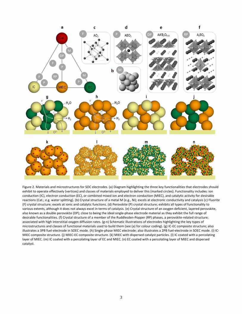
The high operating temperature places significant constraints on electrode, electrolyte and interconnect materials for SOCs. All materials must not be reactive with adjacent components at the high operating temperature, and must have compatible thermal expansion coefficients. Interconnects and electrolytes must be impermeable to gas, provide high conductivities to minimize losses (electronic and ionic, respectively), and be stable in both reducing and oxidizing atmospheres. An ideal cell microstructure would offer an optimized contact between the electrolyte and the electrode, while being dimensionally, mechanically, chemically and thermally stable during operation. Aside from stability and cell integration requirements as well as the mass and electronic transport functions required of the bulk electrode material, the electrochemically active region of a SOC electrode must support three essential functionalities which allow for electrochemical reactions to occur effectively. As indicated in Figure 2a these are: high electrocatalytic activity towards desirable reactions such as H2O splitting or O2 reduction, ionic conduction (IC) and electronic conduction (EC). Often the latter are provided from a single material, as a mixed ionic and electronic conductor (MIEC). Since electrode reactions occur exclusively at discreet locations where these functionalities converge in the presence of reactants, these locations also constitute the active areas within the electrode structure. To ensure high power output or efficient electrolysis, electrodes must be designed with an extended active surface area through adequate choice of materials, microstructures and porosity, as illustrated in Figure 2. For example, for composite electrodes consisting of EC and IC phases, the active areas are located exclusively at the interface between the EC, the IC and the gas phase, as illustrated in Figure 2g, hence these are referred to as three phase boundary (3PB) points. If the electrode is a MIEC then the entire electrode surface exposed to the reacting gas might in principle be active towards electrochemical reactions (see Figure 2h); the reactions take place at the solid/gas two phase boundary (2PB). Other, more elaborate electrode microstructures may be used to maximise 3PB and/or 2PB regions, as shown in Figure 2l-n, by selecting dedicated materials to fulfil desired functions (Figure 2a). A more comprehensive overview of materials and microstructures used in SOCs can be found in previous reviews1–5.
3
g h i j
k l m n
Figure 2. Materials and microstructures for SOC electrodes. (a) Diagram highlighting the three key functionalities that electrodes should exhibit to operate effectively (vertices) and classes of materials employed to deliver this (marked circles). Functionality includes: ion conduction (IC), electron conduction (EC), or combined mixed ion and electron conduction (MIEC), and catalytic activity for desirable reactions (Cat.; e.g. water splitting). (b) Crystal structure of a metal M (e.g., Ni); excels at electronic conductivity and catalysis (c) Fluorite (F) crystal structure; excels at ionic and catalytic functions. (d) Perovskite (P) crystal structure; exhibits all types of functionality to various extents, although it does not always excel in terms of catalysis. (e) Crystal structure of an oxygen deficient, layered perovskite, also known as a double perovskite (DP); close to being the ideal single-phase electrode material as they exhibit the full range of desirable functionalities. (f) Crystal structure of a member of the Ruddlesden-Popper (RP) phases, a perovskite-related structure; associated with high interstitial oxygen diffusion rates. (g-n) Schematic illustrations of electrodes highlighting the key types of microstructures and classes of functional materials used to build them (see (a) for colour coding). (g) IC-EC composite structure; also illustrates a 3PB fuel-electrode in SOEC mode. (h) Single-phase MIEC electrode; also illustrates a 2PB fuel-electrode in SOEC mode. (i) IC-MIEC composite structure. (j) MIEC-EC composite structure. (k) MIEC with dispersed catalyst particles. (l) IC coated with a percolating layer of MIEC. (m) IC coated with a percolating layer of EC and MIEC. (n) EC coated with a percolating layer of MIEC and dispersed catalyst.

4
3. Understanding the interface
3.1 Characterization and modelling of the interface One of the earliest and most insightful tools used in SOC characterization is impedance spectroscopy (IS). In this, alternating current or voltage is applied to measure the impedance of a SOC over a wide range of frequencies which enables the separation of different processes, based on their electrical relaxation times. These processes can then be systematically studied and modelled to gain insight into their electrochemical properties6. One example highlighting the correlation between measured impedance and corresponding processes at the interface7 is given in Figure 3a. Since IS can be carried out in situ and in operando, this technique has provided invaluable insight into SOC interface processes over the years8,9. Information from IS is often complemented or best interpreted in conjunction with information on the structure of the active interface at different scales. A microstructure overview may be obtained by scanning electron microscopy and 3D reconstruction based on focused ion beam (FIB) tomography. The latter has been successfully used to characterize quantitatively the 3PB region in Ni-YSZ composite electrodes10 (see Figure 3b), although its destructive nature means that it is not applicable for in situ or real-time studies. A noteworthy alternative to this is X-ray computed tomography which is non-invasive, displays sub 50 nm resolution and does not require operation under vacuum, making it particularly suited for in situ and possibly even for in operando studies11. Whilst an overview of the interface microstructure is essential, to fully understand and control it, it is equally important to obtain information on the two sub-regions that underpin its functionality, the bulk and the surface. The bulk is largely responsible for transport processes (e.g. O2- and e-) while the surface is responsible for species exchange (e.g. OH-, O-, O2- and e-) and catalytic processes. The bulk composition, crystal and electronic structure may be probed by X-ray and neutron diffraction experiments, and X-ray absorption spectroscopy, respectively. These may be set up in situ together with IS measurements to provide a comprehensive view of the bulk structural changes and electrochemical processes occurring at SOC electrodes12,13. Various techniques are used to probe the surface at various depths, including secondary ion mass spectrometry (tens to hundreds of nm)14,15, X-ray electron spectroscopy (XPS, 1-10 nm) and low-energy ion scattering (the outer atomic monolayer, i.e. the very surface involved in reactions with the gas phase)15,16. Raman spectroscopy can be used to map surface species (e.g., oxygen, sulphur, carbon, hydrocarbons and water) involved in the electrode reactions. XPS and Raman may also be used in situ in conjunction with IS measurements providing mechanistic insight by linking surface chemistry to electrochemical performance17,18. More recently, computational methods such as density functional theory have been employed to complement the above mentioned techniques to probe and predict the structure and properties of local interfaces at an atomic scale. Such methods may inform on bulk and surface structure, transport and mobility of oxygen and electrons, and ultimately electrode reaction mechanisms. One example is included in Figure 3c illustrating the mechanism and energy barrier involved during oxygen migration in a perovskite structure19. A more comprehensive view of the tools used in the characterisation and modelling of SOC electrodes and active interfaces is given in ref20.

5
a b
c
Figure 3. Tools and models for understanding active interfaces. (a) IS measurement and corresponding analysis using the Adler-Lane-Steel model for a porous mixed-conducting oxygen electrode 7. The figure highlights the correspondence between processes occurring at the electrolyte-electrode interface region (e.g. electron and oxygen transfer/transport) and the features observed in the imaginary vs real impedance components plot. (b) 3D reconstruction by FIB tomography of a Ni-YSZ cermet showing the Ni (green), YSZ (grey), pore (blue) phases, and corresponding 3D map of the 3PBs10. The majority of the 3PB length (63%) is connected and shown in grey10. However, a substantial amount of 3PB length (shown in colours other than grey) consist of shorter, disconnected 3PB segments and therefore are expected to display negligible contribution towards overall electrode performance. (c) Trajectory (top and side view) and corresponding energy of oxygen migration in a perovskite structure (LSM) by computational methods19. For clarity, oxygen ions involved in diffusion are shown in yellow; V, O1 and O2 indicate the vacancy and the initial and final states of oxygen ion conduction, respectively. Oxygen diffusion follows a curved pathway with respect to the B-ion and between the triangle described by two A-ions and the B-ion.
3.2 Electrochemical reaction mechanisms Due to the complexity of SOC electrode reactions and the difficulty of studying them as they happen, there is
still contention about certain aspects. However, recent progress in the development and use of in situ and in
operando techniques to probe structure, chemistry and functional properties at the active interface
simultaneously and at different scales,20,21 will surely have a positive effect on this field. In Box 1 we outline the
general aspects of the typical electrode reactions to provide a basis to elaborate the following discussion
relating to evolution of the electrochemical interface..

6
Box 1 SOC Electrochemical Reaction Mechanisms O2-electrode. The active oxygen electrode material generally has perovskite or related structure, Figure 2d-f. For poorly ionic conducting oxygen electrodes, such as SrO doped LaMnO3 (LSM), the 3PB path dominates under anodic polarisation, gradually shifting to the 2PB path with cathodic polarisation22, due to the reduction of Mn, which increases the oxygen vacancy concentration. For MIEC oxygen-electrode materials the 2PB pathway dominates. For most perovskites, the electrode polarisation resistance (Rp) is dominated by the oxygen surface exchange reaction23 with the rate determining step involving both oxygen vacancies and molecular oxygen24. Recent experimental findings show that near surface oxygen anions demonstrate significant redox activity in relation to oxygen adsorption, associated with strong hybridization between oxygen 2p and transition metal 3d electronic states25. In most practical electrodes the perovskite component is in a composite with an oxide conducting fluorite, and this is essential for perovskites of low ionic conductivity. Furthermore, interfacial strain that may develop in nanocomposites can offer an additional independent parameter for optimizing oxygen exchange and transport. Interestingly, oxygen exchange rates much higher than those of the individual compounds have been reported for (La,Sr)CoO3-δ/(La,Sr)2CoO4-δ composites and heterostructures26. Fuel-electrode. For typical SOC fuel-electrodes, comprising a porous composite of Ni and stabilized zirconia, the electrochemical reaction occurs near the 3PBs (see Figure 2g). The mechanism of H2 oxidation and H2O reduction and the nature of the rate determining step remain controversial, with adsorption/desorption, surface diffusion, and charge-transfer reactions suggested27. The schematics of three proposed hydrogen electrode mechanisms (a, b, c) are shown below with d illustrating the influence of impurities. Several ceramic materials such as doped ceria and perovskite structured oxides have emerged as excellent MIEC electro-catalysts for H2 oxidation and H2O reduction,1,5 extending the reaction to the entire ceramic/gas interface (2PB)28 with the surface reaction being rate determining28,29.
Schematic mechanism for hydrogen reduction at a Ni/SZ 3PB. a) H2 adsorption and dissociation on the Ni results in the formation of species such as H+ ions which migrate to the site for water formation along the surfaces or through bulk Ni and SZ. b) migration of O2- or OH- from the SZ to the Ni along surfaces to the water formation site on the Ni. c) water formation takes place at the SZ surface and electron transport is occurring at the surface of or through the SZ. d) influence of impurities at interfaces: an impurity film covering the SZ surface with an impurity ridge located at the three phase boundary. The impurity film and ridge may often consist of a glassy silicate phase (see below) and the reactions in a-c must take place through or around this phase which thus has the ability to restrict or block the reactions27.

7
4. Evolution of the Interface
4.1 Segregation and Contamination at the interface
Normally, a surface having the bulk arrangement of atoms will not be the one with the lowest free energy, G, due to the dangling bonds of the surface atoms. Thus there is driving force for rearranging the surface and near surface atoms. The extent and speed of the rearrangement is dependent on several parameters, such as atmosphere, temperature, polarisation, lattice structure, composition and nonstoichiometry, and ion mobility. If the crystal contains two or more elements with different ion size then the rearrangement will typically involve some degree of enrichment or depletion compared to the bulk composition. This segregation of constituents and impurities to the interfaces of ceramics generally leading to deterioration of surface properties and functionality has been a long-standing subject of investigation.30 In this context, perovskite oxides ABO3 (Figure 2d) and related structures, double perovskite AA’B2O5+δ (DP, Figure 2e) and Ruddlesden-Popper An+1BnO3n+1 (RP, n = 1 shown in Figure 2f), are of particular importance. These structures exhibit a remarkable array of functionalities for both oxygen and fuel electrodes (Figure 2a), yet are hindered by surface reorganisation effects. Structurally, perovskites are underpinned by large cations on the A-site (usually lanthanide and/or alkaline earth) and smaller cations on the B-site (typically first row transition metals). Since the difference in cation size seems to largely drive surface segregation and reorganisation processes31, it seems that perovskite structures are fundamentally prone to such effects. Usually it is the larger A-site cations that segregate to the surface, forming AO islands15,31,32 or an An+1BnO3n+1 RP-type layer16,32,33 which can be several nanometres thick16 (see Figure 4a). This in turn means that the B-sites are less exposed to the free surface, or otherwise obstructed from contact with the reactants16,32. Since the transition metal cations on the B-site are generally responsible for the catalytic, oxygen and electron transfer functions, this has obvious negative effects on material and implicitly SOC performance. For example the segregation of SrO to the perovskite surface hinders the oxygen reduction reaction by inhibiting electron transfer from the perovskite bulk to oxygen species adsorbing onto the surface and by diminishing the concentration of oxygen vacancies available on the surface for incorporating oxygen into the lattice32 (see Figure 4a). If the segregated layers are converted by strong reduction of the perovskite material (2 V)34 or removed by dissolution in aqueous HCl solution14 then the current density increases by orders of magnitude. In spite of this, recent investigations could not establish any clear correlation between the SrO segregation and the surface oxygen exchange rate on RP-type O2-electrodes15,35, suggesting that our understanding of the SOC electrode process related to surface reorganisation is still incomplete. Nonetheless, recent reports suggest that surface segregation in perovskites may be minimised by adequate choice of A-site cations and perovskite defect chemistry31,36,37. Degradation due to impurities is widely thought to be most significant when the contaminations impact the active electrode zone. The most studied example is chromium poisoning on the air electrode side arising from interconnect materials and even in gas phase from steel housing. This subject has been comprehensively reviewed38 although the nature of the process has not been fully resolved. A highly likely model involves electrochemical deposition of CrOx impurities at the 3PB, Figure 4b, however the possibility of chemical deposition cannot be fully discounted. Jiang has also recently proposed a nucleation model that suggests that surface A-site enrichment is a key factor in initiating the Cr deposition38. Impurity compounds with a relatively high degree of covalent bonding such as SiO2 tend to lower the surface energy of ionic oxide surfaces. Therefore, the rearrangement tendency is in particular pronounced for the surfaces and interfaces of common SOC electrolytes such as stabilized (doped) zirconia and doped ceria. They tend to become covered by glassy phases consisting of SiO2, Na2O and other oxides, which may originate from the raw materials, the supplied gases or auxiliary components such as sealing glasses. Even in case of very clean single crystals a "mono-layer" of impurities of similar "glassy" composition is usually observed on the surface of

8
yttria and or scandia stabilized zirconia (YSZ, ScSZ) 39,40. Furthermore, dopants like Y2O3 in YSZ and Gd2O3 in ceria gadolinia oxide (CGO) segregate to the grain boundaries as well as to the interface between the bulk crystal and the glassy surface layer39,41. The degradation of the widely used Ni-YSZ cermet SOC fuel electrode seems to be very much dependent on the impurity type and level in the raw materials as well as in the fuel gas, as demonstrated experimentally by using model electrodes. Figure 4c, which shows atomic force microscopy (AFM) micrographs of YSZ/Ni interfaces after electrochemical testing and removal of the Ni model electrode.
A b
c
Figure 4 Segregation and contamination at the interface. (a) Schematic diagram of A-cations segregation to the surface of perovskites (adapted from ref 16). Segregation occurs typically over 1-10 nm depth, with formation of AO islands or A-cation rich RP layers and likely a sub-surface B-cation rich layer. Such surface reorganisation limits overall functionality for electrode reactions such as oxygen reduction. (b) Possible scheme of Cr deposition at the LSM/YSZ interface according to an electrochemical deposition model with formation of Cr2O3 at the 3PB (adapted from ref 38). (c) AFM micrographs of the YSZ side of Ni-YSZ interfaces after few days of testing at 1000 °C in wet hydrogen (97% H2/3% H2O)42,43; left 99.8 % pure Ni, right 99.99 % pure Ni.
Variations in concentration and type of impurities at the 3PB are believed to be mainly responsible for the huge variation in performance (several orders of magnitude) and properties such as activation energy and dependency of performance on H2O partial pressure that are reported for nominally equal electrodes44. The performance of a doped ceria mixed conducting electrode has been shown to strongly depend upon the degree of coverage of SiO2 glass45. A SiO2 scavenger (such as basic oxides of Sr or La) is probably the most effective means of combatting segregation at the 3PBs46. It might also be expected that this segregated SrO would react with the SiO2 impurities discussed above at the 3PB, and this actually seems to happen, but it does not block the oxygen reduction or the oxide ion oxidation totally22.

9
3.2 Passivation and activation phenomena It is clear that although the 3PB and 2PB electrochemical reaction zones are simple concepts, in actual operating electrodes they are highly dynamic interfaces that present complex and changing landscapes at the nanoscale. The changes that take place -- such as accumulation or removal of impurities, enrichment of inactive or active surface species, solid-solid interfacial reactions, crystallographic phase transitions, and coarsening or formation of nanostructures -- can be either beneficial or detrimental to the electrochemical activity, and they can be reversible or irreversible. Here, the term “activation” is used to describe a beneficial decrease of interfacial resistance, whereas “passivation” and “degradation” describe reversible and irreversible increases, respectively. Following is a summary of a number of mechanisms by which the electrochemical interfaces can undergo activation and passivation during cell operation. Considering 3PB-based electrodes, the conventional LSM/YSZ/O2, Figure 5a, and Ni/YSZ/H2, H2O, figure 5b, interfaces exhibit a variety of activation/passivation phenomena. The widely known activation of LSM by cathodic polarisation (fuel-cell mode) is at least partly due to the increase in oxygen vacancy concentration described earlier, which is a result of reduction of Mn3+/4+ to Mn2+. The LSM/O2 2PB becomes active. Additionally, the reduced Mn cations spread out on the YSZ surface, leading to further enhancement of the electrochemical activity as the Mn-enriched YSZ/O2 2PB effectively becomes active for direct oxygen incorporation47. The process is reversible; anodic polarisation causes Mn diffusion back to LSM and re-oxidizes the Mn ions, restoring the 3PB-dominated reaction zone and its lower electrochemical activity. For LSM and other oxygen-electrodes, applying too high anodic overpotential for long periods of time (when performing electrolysis) causes microstructure degradation at the electrode/electrolyte interface48–50. The interfacial oxygen pressure, which varies exponentially with the overpotential, can become high enough to precipitate pressurized oxygen bubbles in closed cavities and/or to force oxygen incorporation into the LSM crystal lattice, eventually weakening and cracking the interface. Clearly, this type of failure can be considered a severe degradation mechanism. However, it was recently discovered that periodic reversal of the polarisation can avoid the damage51,52, blurring the line between passivation and degradation. The cathodic polarisation periods relieve the built-up oxygen pressure, but it is not yet clear if this must occur before or after structural deterioration has started -- afterwards implies that nano/microcracks that have begun to form are sintered back together during cathodic periods51. There is some disagreement in literature about the precise mechanisms of cathodic activation51,53 and anodic degradation, which seem to depend critically on the details of the interface in a particular cell, e.g. the thermal history, nano/microstructure, and composition (enrichment/deficiency of different cations and presence of secondary phases). The precise stoichiometry (in particular the A/B cation ratio of the perovskite) and the uncertainty of the precise stoichiometry are important, often under-reported details. At Ni/YSZ/H2,H2O 3PBs, the most common passivation/activation process is sulphur poisoning54,55. At low H2S concentrations and high temperatures, sulphur reversibly adsorbs on Ni, desorbing when the H2S supply is removed. Adsorbed sulphur partially blocks the 3PB, lowering the electrochemical reaction rate. Higher concentrations lead to irreversible formation of nickel sulphide. The detrimental effect of sulphur is more severe in cathodic polarisation (electrolysis mode), which provides a transport gradient for gas-phase impurities towards the 3PBs55. Another way to unblock the 3PB is to form a new one in situ. Activation by rearranging the Ni/YSZ interfaces can be accomplished by carefully leaving and returning to the thermodynamic stability regime of Ni and YSZ. Oxidizing the Ni to NiO, either by exposure to a high oxygen partial pressure (pO2) gas (such as air) or by high anodic polarisation, followed by reduction back to Ni, leads to a fresh 3PB and enhancement of electrochemical activity56,57. This “redox cycle” must be performed at the right conditions and with an appropriate porous electrode microstructure in order to avoid breaking the porous YSZ skeleton by the large Ni-NiO volume change56. On the other end of the pO2 spectrum is activation by the partial reduction of YSZ, in which brief applications of high cathodic polarisation drive the formation of a more active,

10
nanostructured Ni/YSZ/H2,H2O 3PB58–60. Prolonged exposure to high cathodic overpotential, however, can lead to undesirable nanostructure morphologies characterized by Ni/YSZ contact loss61.
Figure 5. Electrode potential-driven activation and passivation phenomena. ., (a) the LSM/YSZ/O2 3PB and (b) the Ni/YSZ/H2,H2O 3PB. MIEC oxygen-electrodes exhibit the same activation and degradation mechanisms as LSM at high negative and positive potentials. At low overpotentials, MIEC oxygen-electrodes have an active 2PB like LSM does under cathodic polarisation (a) but without Mn2+ spreading. MIEC fuel-electrodes generally show considerable activation under cathodic polarisation. The effects of high anodic or cathodic overpotentials on MIEC fuel-electrodes are expected to differ from Ni/YSZ but remain to be investigated.

11
MIECs provide electrochemical reaction sites on the entire surface (MIEC/O2 or MIEC/H2,H2O 2PB, see Figure 2h), making them less susceptible to blockage by impurities than 3PB-based electrodes. In mixed conductors, the oxygen vacancy concentration (and thereby electrochemical activity) varies with pO2 (or polarisation) and temperature. Short treatments of high cathodic – and anodic to a lesser extent – polarisation were found to dramatically improve the reaction rate at the MIEC/O2 2PB by up to two orders of magnitude depending on the MIEC material62. The enhancement was attributed to a modified, non-equilibrium cation stoichiometry observed on the surface of activated electrodes, which has a lasting effect after the treatment34. High cathodic polarisation may be expected to even totally decompose the electrochemically active part of the perovskite surface, after which a fresh, more active surface is formed. Besides overpotential, adjusting the operating temperature has been found to cause reversible activation/passivation of LSM and MIEC oxygen-electrodes63. A similar mechanism was proposed: upon returning to lower temperature after a period at higher temperature, the resistance of the activated electrode slowly increases to the previous value as the surface re-equilibrates. In the fuel environment, the activity of the MIEC/H2,H2O 2PB, as observed for CGO and other low-pO2 MIECs, considerably increases when reduced by cathodic polarisation and decreases when oxidized by anodic polarisation, corresponding to the pO2 changes29,60,64,65. Interestingly, MIECs are often activated by redox cycles, even those that are chemically and dimensionally stable both in air and fuel environments. Coatings of (La,Sr)(Cr,Mn)O3 (LSCM) or CGO nanoparticles on certain ionic or electronic conducting backbones have been observed to change morphology and surface area after a redox cycle58,66,67. Finally, more extreme surface changes driven by exposure of certain oxides to low pO2 or cathodic polarisation is the exsolution of reduced (metallic or oxide) nanoparticles from the oxide, which can be reversed by redox cycles. With respect to long-term stability, the possibility for periodic activation to counteract losses in performance is of great practical interest.
5. Designing and manipulating advanced interface architectures
5.1 Impregnation Impregnation, or infiltration, is a technique that has been used extensively in the field of heterogeneous catalysis to immobilise high surface area catalytic particles onto ceramic support materials, such as alumina, silica and zirconia68,69. To this end, precursor solutions of the catalytically active materials are used to wet the surface of the support (see Figure 6). The final microstructure is obtained after drying and decomposing the precursor, leaving the nanosized metal or metal oxide particles behind (Figure 6). Often, in situ reduction is required to create metal particles. Due to the high surface area nature of the nanosized catalyst, small loadings of typically 1 – 10 wt.% are required to obtain high activity. This technique has now been used for some 15 years to enhance and modify SOC electrodes. Impregnation does require at least one mechanically strong porous component, or backbone, which is processed using conventional high temperature ceramic routes. This is often the electrolyte component (stabilised zirconia or doped ceria), but can be an electronically or mixed conducting ceramic too (see Figure 6). The flexibility that impregnation offers in terms of mix-and-match of various electrode functionalities (i.e. mechanical support, ionic conductivity, electronic conductivity, oxidation/reduction electrocatalyst) has led to many researchers adopting this approach in SOC development. Some excellent comprehensive reviews have already been written on this subject and are referred to for a complete overview4,70–73. This review aims to highlight some recent advances that constitute a step change for impregnated SOC technology, be it in performance, processing or scale. Researchers at the University of Pennsylvania were amongst the first to use a simple porous skeleton of stabilised zirconia (YSZ) as the mechanical support (with ionic conductivity), whilst using impregnation techniques to create electronic pathways and deposit electrocatalysts (e.g. Figure 2m). By impregnating combinations of copper, ceria and palladium into the fuel-electrode backbone to replace conventional nickel, SOFC operation was thus possible without coking issues when using hydrocarbon fuels in absence of excess

12
steam3. Impregnated SOFC fuel-electrode development has since focused on both modifying conventional nickel cermets as well as using alternative fuel-electrode materials4. Modifying nickel cermet fuel-electrodes predominantly aims at improving coking and sulphur tolerance, whilst some claims are made it can improve long term stability too72. Typical impregnates to these ends are copper, iron, ruthenium, palladium and (doped) ceria. Impregnating nickel into porous stabilised zirconia backbones, rather than sintering as a conventional composite, has even been shown to alleviate mechanical problems on redox cycling4. To date, modified strontium titanate, SrTiO3 and lanthanum chromite, LaCrO3 form the most widely studied families of alternative oxide fuel-electrode materials, due to their stability over a wide range of oxygen partial pressures and moderate electronic conductivities, offering redox stability and tolerance towards coking and sulphur poisoning. These materials may be used either as impregnates (Figure 6b) or as conductive backbones (Figure 6a). Further impregnating with ceria or transition metals is often required to add catalytic activity towards the fuel oxidation (Figure 5a)4,72. Similarly, in SOFC oxygen-electrode development impregnation of (La,Sr)MnO3 (LSM) into porous electrolyte backbones (similar to Figure 6c) has enabled much improved performance as compared to conventionally processed LSM based oxygen-electrodes, due to the increase in catalytic surface area for oxygen reduction. Further enhancement can be achieved by additionally impregnating with catalysts such as ceria and
palladium71. Cobaltites and ferrites, such as La1-xSrxCo1-yFeyO3- (LSCF) and Sm0.5Sr0.5CoO3- (SSC) are promising oxygen-electrode materials in intermediate temperature fuel cells due to their high ionic conductivities, but have stability issues due to their reactivity with zirconia at typical sintering temperatures. The unique low processing temperatures during impregnation are an effective way of avoiding such reactions70,73. Surface modification may be used for reasons other than promoting catalytic activity or adding conduction pathways. It was shown that by impregnating 30 wt.% of CGO into LSCF oxygen-electrodes, chromium poisoning from a typical metallic interconnect was greatly reduced, showing that the technique can be used to add chemical protection from contaminants as well74. Despite the large potential for fabricating solid oxide cells by impregnation methods, some issues still need to be addressed. Microstructural control and its long term stability are still a matter of concern. Due to the large surface area of impregnates, microstructural coarsening is a particular problem under typical SOC operation conditions. Control of microstructure during fabrication is very dependent on the surface chemistries of the support material and the impregnates. Lou et al. showed that matching the wettability of the impregnation solution to the support material can greatly improve resulting microstructures and electrochemical performance75. Other issues are the scalability and time consumption of the technique. In order to impregnate 30 wt.% of an active component, for instance to create a percolating network, a great many consecutive impregnation/heat treatment cycles may be required to achieve such loading, raising questions about this technique’s industrial readiness. A promising method for reducing this number of cycles is suggested by Choi et al, who use a layer-by-layer assisted method for impregnation76. This method involves pre-treating the support material’s surface to enhance its affinity for the impregnates. They claim this technique reduces the fabrication time by 6 – 7 times, whilst increasing the electrodes surface area by 24%. Impregnating molten salts instead of dilute precursor solutions has been suggested as another way to efficiently deposit large quantities of active phases77. In terms of scalability, a number of recent studies report on SOFC tests on industrially relevant scales, an overview of which is available in Table 1. The various cells and systems presented comprise a range of cell geometries, including a self-supported YSZ scaffold impregnated with both fuel-electrode and oxygen-electrode components78. Particularly promising seems a number of studies assessing the use of A-site deficient SrTiO3 fuel-electrode backbones, impregnated with various catalysts79–81. Not only are competitive performances retained on scaling up (up to P = 0.7 W/cm2), reasonable degradation rates are shown as well, i.e. 5 – 6 %/kh, over 300 – 1000 hours of testing80,81. The role of support-impregnate interaction on long term performance is illustrated by the fact that Nb doped SrTiO3 fuel-electrodes impregnated with Ru/CGO exhibit

13
much improved stability (0.04 mV/h) over those impregnated with Ni/CGO (0.5 mV/h) under identical testing conditions80. Long term stability of impregnated electrodes was also shown to be largely affected by operating temperature81. A full system test of nominally 1 kW was operated under relevant conditions (reformed natural gas, 850°C), which to date is the largest scale test of this kind using alternative fuel-electrode materials and impregnated electrodes81. Table 1: Technologically-relevant SOFCs using impregnated electrodes
Cell geometry
Cell size (cm2)
Fuel-electrode Oxygen-electrode Testing conditions Peak performance (W/cm2)
Ref.
Fuel-electrode supported
100 Ni/YSZ cermet La0.6Sr0.4Co0.2Fe0.8O3- impregnated in YSZ
Single cell, 750°C, H2 vs. air
0.47 82
Self-supported
25 La0.3Sr0.7VO4- with CeO2 and Pd impregnated in YSZ
La0.8Sr0.2FeO3- impregnated in YSZ
Single cell, 800°C, 4% H2O / H2 vs. air
0.49 78
Fuel-electrode supported
25 Ni with Ce0.9Gd0.1O1.95 impregnated in La0.2Sr0.7TiO3
La0.6Sr0.4CoO3- impregnated in YSZ
Single cell, 850°C, 4% H2O / H2 vs. air
0.19 79
Electrolyte supported
25 Ru with Ce0.8Gd0.2O1.9 impregnated in Sr0.94Ti0.9Nb0.1O3
LSM/YSZ composite Single cell, 850°C, 4% H2O / H2 vs. air
0.7 80
Electrolyte supported
25 Ni with Ce0.8Gd0.2O1.9 impregnated in Sr0.94Ti0.9Nb0.1O3
LSM/YSZ composite Single cell, 850°C, 4% H2O / H2 vs. air
0.3 80
Electrolyte supported
100 Ni with Ce0.8Gd0.2O1.9 impregnated in La0.2Sr0.25Ca0.45TiO3
LSM/YSZ composite 60 cells, 1 kW full system, 850°C, CPOx reformed natural gas vs. air
0.13 81
A
B
C
Figure 6. Selected examples of electrode microstructures prepared by infiltration. (a) An electron conducting perovskite titanate backbone (La,Sr,Ca)1-aTiO3 (illustrated schematically in green), is infiltrated with adequate precursors (orange outline) to form dispersed

14
Ni catalyst particles (red) over the titanate backbone surface. The titanate surface is also modified in the process by addition of a fine layer of CGO MIEC (orange spots). Microstructure exemplified by SEM micrograph(adapted from ref 83). (b) An ionic conducting YSZ backbone (illustrated in dark yellow) is coated with a MIEC perovskite, (La,Sr)(Cr,Mn)O3 (orange outline), by infiltration to form a mosaic-like nano-structure (orange) with a rich 3PB area. Microstructure exemplified by SEM micrograph (adapted from ref 67). (c) An ionic conducting YSZ backbone (illustrated in dark yellow) is coated by infiltration with percolating, electronic conducting (La,Sr)VO3 particles (shown as green outline then green particles). Microstructure exemplified by SEM micrograph (adapted from ref 78).
5.2 Exsolution The most active interfaces are formed ex-situ by assembling the desired phases through sequential deposition processes such as infiltration. However, active interfaces can also be generated in situ, during operation, through a phase decomposition process usually referred to as redox exsolution84–87. In this approach, catalytically active transition metals are substituted in a host oxide lattice in oxidising conditions, forming a solid solution, and released (exsolved) on the surface as metal particles, once the oxide lattice has been reduced to sufficient extent. The most well characterised and effective redox exsolution process demonstrated so far employs perovskites as host oxides due to their unique ability to accommodate defects of different size, charge and nature, in a range of nonstoichiometry classes88. This not only allows for such attractive structural interplay, but also for combining it with other desirable electrode functionality (see Figure 2a), including mixed electronic and ionic conduction to create new and exciting metal-oxide interfaces. Typical systems demonstrated so far include metal particles predominantly consisting of Pd85,89,90, Pt89,91, Rh89,91, Ru86,92 and Ni92–94, on various ferrite85,89, titanate84,87,89,91,95, chromite86,90,94 or chromite-manganite93,96 perovskite supports. These have been applied to solid oxide fuel cells86,90,92,94,97, electrolysis cells95,98 and for other catalytic process36,84,85. Evidence so far suggests that redox exsolution from perovskites is a phase decomposition process driven by reduction and controlled by bulk and surface defects and external conditions36,87,92. Initially the lattice is reduced, losing oxygen and gaining electrons until the point where metal nucleation becomes favourable. Nucleation is likely to occur primarily on the surface of the host lattice where the nucleation barrier is lowered by crystal defects36,92. The surface nucleation process drains exsolvable ions from the nearby perovskite lattice which causes additional reducible ions to diffuse to the surface to balance the compositional gradient and fuel the growth of the metal clusters. In fact, cation diffusion to the surface plays an essential role for sustaining exsolution given that during this process reducible ions from typically at least 100 nm deep emerge on the surface to form metal particles36. Lattice defects such as A-site and oxygen vacancies seem to assist not only with cation and oxygen transport to the surface but also with nucleation. Such vacancies facilitate ion diffusion by minimising lattice collisions and supplying hopping sites36, while creating an apparent B-site excess87, which in turn drives the exsolution of catalytically active species from this site in order to retain stable stoichiometry87. Another important defect that controls exsolution is the surface structuring exhibited by perovskite oxide lattices. Upon processing at high temperatures required to form most catalytic microstructures, perovskite lattices terminate into A-cation rich layers31,33,36 which appear to obstruct exsolution36,87 and interfere negatively with other catalytic perovskite applications, as discussed in section 4.1. This effect is shown in Fig 7a which illustrates that more numerous and better distributed particles exsolve on a freshly cleaved bulk perovskite surface having nominal A-site deficient stoichiometry, as compared to the restructured (native) perovskite surface which is A-cation rich. However, recent results have shown that this effect can be diminished through adequate choice of bulk defect chemistry and seemingly more mobile A-site cations36,87.

15
Aside from the compositional and structural parameters enumerated above, external parameters such as the pO2 or the reduction temperature may be used to control the dispersion, population and size of exsolved particles which allows for tailoring the nanostructure of porous electrodes36,87. The controlled, nucleation-driven manner in which redox exsolution occurs also has unique implications on the structural and functional characteristics of the emergent particles. Fig 7b shows that unlike particles prepared by conventional means, exsolved particles are about one third immersed in the surface of the host lattice36. Moreover, electron diffraction and TEM imaging indicate that particles maintain crystallographic coherence with the host lattice (Fig 7c) and consequently may experience lattice strain36,87. Such confined and seemingly anchored particles are expected to exhibit considerably different physical and chemical properties as compared to unconstrained particles. Not surprisingly, exsolved particles possess enhanced thermal stability and display low tendency to coalesce, even when spaced by less than one particle diameter36. Such enhanced stability is also observed in SOFC92 or other catalytic applications36,84. Another notable consequence of particle anchorage is reflected in their remarkable coking resistance whilst maintain activity for desirable reactions36,84. Ni particles prepared by conventional methods are well known to catalyse the formation of carbon fibres at the interface with the support, resulting in particle uplifting and leading to irreversible catalyst damage in industrially critical processes such as syngas production by methane steam reforming99. Ni particles prepared by exsolution were found to be exceptionally resistant to uplifting and subsequent carbon fibre growth (i.e. coking) in hydrocarbon catalysis (Fig 7d). Emergent particles are also capable of functionalizing the surface of the host lattice for other important reactions, including water electrolysis to hydrogen. Fig 7e shows that when particles exsolve on the surface of an adequately designed A-site deficient perovskite through in situ reduction, a dramatic drop in the onset potential for electrolysis is observed, together with an increase in the amount of hydrogen that can be potentially produced95. Similarly, a threefold increase in power density was observed for SOFCs running H2S/H2 and using A-site deficient perovskite fuel-electrodes as compared to stoichiometric analogues (Fig 7f)94. As mentioned above, A-site deficiency enables more extensive particle exsolution as compared to stoichiometric formulations87, which in turn ensures the creation of significantly more active sites in situ at the fuel-electrode. Another noteworthy functional aspect of redox exsolution is that in certain scenarios it has been shown to be reversible85. Particles may be re-dissolved into the host lattice on oxidation and subsequently re-exsolved upon reduction. Even though this does not appear to be universally applicable or fully reversible100, it may serve as proof of concept that that microstructures and interfaces may be rejuvenated by carrying out controlled redox cycles, thus improving the longevity of certain catalytic systems. In summary, redox exsolution enables a new dimension in the preparation of confined metal particles with unique functionality otherwise inaccessible by conventional preparation methods. Additionally, it could be relatively faster and less wasteful while allowing particle growth at specific, otherwise inaccessible locations in e.g. layered devices by adjusting initial composition in individual layers. For example, catalytically active Ni metal particles can be conveniently exsolved in situ within minutes at the fuel-electrode side of a SOEC consisting of an A-site deficient titanate perovskite layer95.

16
A B C
D E F
Figure 7. Structural and functional properties of exsolved particles. (a) the influence of lattice stoichiometry on particles exsolution (adapted from 87). (b) TEM micrograph showing exsolved particles are partly immersed in the parent host lattice and drawing illustrating this in comparison to conventional metal-oxide interfaces (adapted from 36). (c) TEM micrograph cross-section at the particle-oxide interface together with superimposed atomic detail indicating epitaxy (adapted from 36). (d) False colour SEM micrograph of exsolved Ni particles after hydrocarbon catalysis exhibiting limited coking (adapted from 36). (e) High temperature steam electrolysis performance comparison between a perovskite capable of exsolving Ni metal particles in situ (blue) and one that cannot (red) (adapted from ref 95). (f) SOFC performance in 5000 ppm H2S/H2 with A-site deficient perovskite chromate fuel-electrode displaying extensive exsolution of Ni particles (blue) and a stoichiometric analogue with limited exsolution capabilities (red) (adapted from 94).
6. Outlook
In this article we have shown that the critical processes relating to ageing and performance of SOC devices tend to occur in the electrode - electrolyte interface regions. These present an intricate and dynamic structure that evolves on ageing and upon regeneration. The composition and structure of this interface can be developed by chemical methods such as impregnation and by control of stoichiometry to improve properties and stability. Processes such as dissolution/exsolution and surface cation segregation are intimately linked to each other and to the chemistry governing ageing and activation. Understanding and controlling the evolution of this interface provides the tools to develop the next generations of solid oxide cells; however, there is much to learn about the details of the involved processes. The development and implementation of in situ and in operando techniques, such as ambient pressure XPS, controlled atmosphere high temperature SPM, in-situ Raman, and environmental TEM, which are able to probe structures and chemistry on the nanoscale in 3 dimensions in real time, will greatly enable our ability to optimise future SOC devices so that we can better convert and store electrical energy. Such techniques can, in combination with electrochemical methods, provide detailed information on chemical as well as structural changes as function of parameters like electrode potential, temperature and reactant concentrations. For example, the very important reversible changes in surface

17
chemistry that occur during operation, such as formation of new nanoparticulate phases due to a change in electrode overpotential, cannot by their nature be observed by ex situ measurements. It is widely accepted that there is an evolution in SOC design from electrolyte supported to composite anode supported, to metal supported in what is often termed generations 1,2,3. Here we highlight a similar evolution in functional electrode concepts from single phase electrode, through bulk composite electrodes, to impregnated skeletons and to locally exsolved structures. Overall, the most successful SOCs will involve a high degree of integration of structures from the nanoscale to the macroscale addressing the key required functionalities. Acknowledgements C.C. acknowledges financial support from ECoProbe (DFF – 4005-00129) funded by the Danish Independent Research Council, and C.G. and M.M acknowledge financial support from Energinet.dk through the ForskEL programme “Solid Oxide Fuel Cells for the Renewable Energy Transition” contract no 2014-1-12231. JTSI, MCV and DN acknowledge support from EPSRC Platform Grant EP/K015540/1, EPSRC Tailoring of microstructural evolution in impregnated SOFC electrodes EP/M014304/1 and Royal Society Wolfson Merit Award WRMA 2012/R2. References 1. Atkinson, A. et al. Advanced anodes for high-temperature fuel cells. Nat. Mater. 3, 17–27 (2004).
2. Gauckler, L. J. et al. Solid Oxide Fuel Cells: Systems and Materials. Chim. Int. J. Chem. 58, 837–850 (2004).
3. McIntosh, S. & Gorte, R. J. Direct Hydrocarbon Solid Oxide Fuel Cells. Chem. Rev. 104, 4845–4866 (2004).
4. Gorte, R. J. & Vohs, J. M. Nanostructured anodes for solid oxide fuel cells. Curr. Opin. Colloid Interface Sci.
14, 236–244 (2009).
5. Cowin, P. I., Petit, C. T. G., Lan, R., Irvine, J. T. S. & Tao, S. Recent Progress in the Development of Anode
Materials for Solid Oxide Fuel Cells. Adv. Energy Mater. 1, 314–332 (2011).
6. Irvine, J. T. S., Sinclair, D. C. & West, A. R. Electroceramics: Characterization by Impedance Spectroscopy.
Adv. Mater. 2, 132–138 (1990).
7. Adler, S. B. Limitations of charge-transfer models for mixed-conducting oxygen electrodes. Solid State Ion.
135, 603–612 (2000).
8. Adler, S. B. & Bessler, W. G. in Handbook of Fuel Cells (John Wiley & Sons, Ltd, 2010). at
<http://onlinelibrary.wiley.com/doi/10.1002/9780470974001.f500031/abstract>

18
9. Ebbesen, S. D., Jensen, S. H., Hauch, A. & Mogensen, M. B. High Temperature Electrolysis in Alkaline Cells,
Solid Proton Conducting Cells, and Solid Oxide Cells. Chem. Rev. 114, 10697–10734 (2014).
10. Wilson, J. R. et al. Three-dimensional reconstruction of a solid-oxide fuel-cell anode. Nat. Mater. 5, 541–
544 (2006).
11. Izzo, J. R. et al. Nondestructive Reconstruction and Analysis of SOFC Anodes Using X-ray Computed
Tomography at Sub-50 nm Resolution. J. Electrochem. Soc. 155, B504–B508 (2008).
12. Liu, J., Hull, S., Ahmed, I. & Skinner, S. J. Application of combined neutron diffraction and impedance
spectroscopy for in-situ structure and conductivity studies of La2Mo2O9. Nucl. Instrum. Methods Phys. Res.
Sect. B Beam Interact. Mater. At. 269, 539–543 (2011).
13. Woolley, R. J., Ryan, M. P. & Skinner, S. J. In Situ Measurements on Solid Oxide Fuel Cell Cathodes –
Simultaneous X-Ray Absorption and AC Impedance Spectroscopy on Symmetrical Cells. Fuel Cells 13, 1080–
1087 (2013).
14. Kubicek, M., Limbeck, A., Frömling, T., Hutter, H. & Fleig, J. Relationship between Cation Segregation and
the Electrochemical Oxygen Reduction Kinetics of La0.6Sr0.4CoO3−δ Thin Film Electrodes. J. Electrochem.
Soc. 158, B727–B734 (2011).
15. Téllez, H., Druce, J., Kilner, J. A. & Ishihara, T. Relating surface chemistry and oxygen surface exchange in
LnBaCo2O5+δ air electrodes. Faraday Discuss. 182, 145-157 (2015). doi:10.1039/C5FD00027K
16. Druce, J. et al. Surface termination and subsurface restructuring of perovskite-based solid oxide electrode
materials. Energy Environ. Sci. 7, 3593–3599 (2014).
In this paper Druce et al provide valuable insight into the surface reorganization in a range of perovskites relevant for SOC applications, which is essential for understanding and controlling surface-related phenomena at the electrochemical interface. 17. Zhang, C. et al. Measuring fundamental properties in operating solid oxide electrochemical cells by using in
situ X-ray photoelectron spectroscopy. Nat. Mater. 9, 944–949 (2010).
18. Li, X. et al. High-temperature surface enhanced Raman spectroscopy for in situ study of solid oxide fuel cell
materials. Energy Environ. Sci. 7, 306–310 (2013).

19
Li et al report on the development of high temperature surface enhanced Raman spectroscopy which represents an important step towards in situ and in operando study of SOC electrode surfaces for obtaining mechanistic insight into electrochemical processes. 19. Choi, Y., Lin, M. C. & Liu, M. Rational design of novel cathode materials in solid oxide fuel cells using first-
principles simulations. J. Power Sources 195, 1441–1445 (2010).
20. Liu, M., Lynch, M. E., Blinn, K., Alamgir, F. M. & Choi, Y. Rational SOFC material design: new advances and
tools. Mater. Today 14, 534–546 (2011).
21. Traulsen, M. L. et al. Need for In Operando Characterization of Electrochemical Interface Features. ECS
Trans. 66, 3–20 (2015).
22. Hansen, K. V., Norrman, K., Jacobsen, T., Wu, Y. & Mogensen, M. B. LSM Microelectrodes: Kinetics and
Surface Composition. J. Electrochem. Soc. 162, F1165–F1174 (2015).
23. Baumann, F. S., Fleig, J., Habermeier, H.-U. & Maier, J. Impedance spectroscopic study on well-defined
(La,Sr)(Co,Fe)O3−δ model electrodes. Solid State Ion. 177, 1071–1081 (2006).
24. Kuklja, M. M., Kotomin, E. A., Merkle, R., Mastrikov, Y. A. & Maier, J. Combined theoretical and
experimental analysis of processes determining cathode performance in solid oxide fuel cells. Phys. Chem.
Chem. Phys. 15, 5443–5471 (2013).
25. Mueller, D. N., Machala, M. L., Bluhm, H. & Chueh, W. C. Redox activity of surface oxygen anions in oxygen-
deficient perovskite oxides during electrochemical reactions. Nat. Commun. 6, (2015).
26. Sase, M. et al. Enhancement of oxygen exchange at the hetero interface of (La,Sr)CoO3/(La,Sr)2CoO4 in
composite ceramics. Solid State Ion. 178, 1843–1852 (2008).
27. Mogensen, M., Ho̸gh, J., Hansen, K. V. & Jacobsen, T. A Critical Review of Models of the H2/H2O/Ni/SZ
Electrode Kinetics. ECS Trans. 7, 1329–1338 (2007).
28. Chueh, W. C., Hao, Y., Jung, W. & Haile, S. M. High electrochemical activity of the oxide phase in model
ceria–Pt and ceria–Ni composite anodes. Nat. Mater. 11, 155–161 (2012).
29. Feng, Z. A., El Gabaly, F., Ye, X., Shen, Z.-X. & Chueh, W. C. Fast vacancy-mediated oxygen ion incorporation
across the ceria–gas electrochemical interface. Nat. Commun. 5, (2014).

20
30. Nowotny, J. Science of Ceramic Interfaces II. (Newnes, 1995).
31. Lee, W., Han, J. W., Chen, Y., Cai, Z. & Yildiz, B. Cation Size Mismatch and Charge Interactions Drive Dopant
Segregation at the Surfaces of Manganite Perovskites. J. Am. Chem. Soc. 135, 7909–7925 (2013).
Lee et al provide a mechanistic model for the segregation and reorganization observed at the surface of perovskite materials, highlighting means to control it with anticipated benefits in enhancing the electrochemical activity of perovskite-based SOC electrodes. 32. Chen, Y. et al. Impact of Sr segregation on the electronic structure and oxygen reduction activity of
SrTi1−xFexO3 surfaces. Energy Environ. Sci. 5, 7979–7988 (2012).
33. Szot, K. & Speier, W. Surfaces of reduced and oxidized SrTiO3 from atomic force microscopy. Phys. Rev. B
60, 5909–5926 (1999).
34. Baumann, F. S. et al. Strong Performance Improvement of La0.6Sr0.4Co0.8Fe0.2O3−δ SOFC Cathodes by
Electrochemical Activation. J. Electrochem. Soc. 152, A2074 (2005).
35. Tomkiewicz, A. C., Tamimi, M. A., Huq, A. & McIntosh, S. FD electrolysis: is the surface oxygen exchange
rate linked to bulk ion diffusivity in mixed conducting Ruddlesden–Popper phases? Faraday Discuss. 182,
113-127 (2015). doi:10.1039/C5FD00014A
36. Neagu, D. et al. Nano-socketed nickel particles with enhanced coking resistance grown in situ by redox
exsolution. Nat. Commun. 6, (2015).
Neagu et al compare the key structural and physicochemical properties of nickel metal particles prepared by deposition and exsolution methods, highlighting the latter as highly promising for enhancing the functionality of perovskite-supported metal particles for range of applications, including SOCs. 37. Chen, Y. et al. Advances in Cathode Materials for Solid Oxide Fuel Cells: Complex Oxides without Alkaline
Earth Metal Elements. Adv. Energy Mater. 5, DOI: 10.1002/aenm.201500537 (2015).
38. Jiang, S. P. & Chen, X. Chromium deposition and poisoning of cathodes of solid oxide fuel cells – A review.
Int. J. Hydrog. Energy 39, 505–531 (2014).
39. Nowotny, J., Sorrell, C. C. & Bak, T. Segregation in zirconia: equilibrium versus non-equilibrium segregation.
Surf. Interface Anal. 37, 316–324 (2005).

21
40. Hansen, K. V. & Mogensen, M. Absence of Dopant Segregation to the Surface of Scandia and Yttria Co-
Stabilized Zirconia. Electrochem. Solid-State Lett. 15, B70–B71 (2012).
41. Mogensen, M. & Hansen, K. V. Handbook of Fuel Cells: Advances in Electrocatalysis, Materials, Diagnostics
and Durability. 5, (Wiley, 2009).
42. Vels Jensen, K., Primdahl, S., Chorkendorff, I. & Mogensen, M. Microstructural and chemical changes at the
Ni/YSZ interface. Solid State Ion. 144, 197–209 (2001).
43. Hansen, K. V., Norrman, K. & Mogensen, M. H2 H2O Ni YSZ Electrode Performance Effect of Segregation to
the Interface. J. Electrochem. Soc. 151, A1436–A1444 (2004).
44. Mogensen, M. & Holtappels, P. in Solid Oxide Fuels Cells: Facts and Figures (eds. Irvine, J. T. S. & Connor, P.)
(Springer London, 2013). at <http://link.springer.com/10.1007/978-1-4471-4456-4>
45. Zhao, L., Perry, N. H., Daio, T., Sasaki, K. & Bishop, S. R. Improving the Si Impurity Tolerance of Pr0.1Ce0.9O2−δ
SOFC Electrodes with Reactive Surface Additives. Chem. Mater. 27, 3065–3070 (2015).
46. Larsen, P. H., Mogensen, M., Hendriksen, P. V., Linderoth, S. & Ming, C. Removal of impurity phases from
electrochemical devices. (2009). at <http://www.google.com/patents/EP2031677A1>
47. Backhaus-Ricoult, M. et al. In-situ study of operating SOFC LSM/YSZ cathodes under polarization by
photoelectron microscopy. Solid State Ion. 179, 891–895 (2008).
48. Knibbe, R., Traulsen, M. L., Hauch, A., Ebbesen, S. D. & Mogensen, M. Solid Oxide Electrolysis Cells:
Degradation at High Current Densities. J. Electrochem. Soc. 157, B1209 (2010).
49. Chen, K. & Jiang, S. P. Failure mechanism of (La,Sr)MnO3 oxygen electrodes of solid oxide electrolysis cells.
Int. J. Hydrog. Energy 36, 10541–10549 (2011).
50. Tietz, F., Sebold, D., Brisse, A. & Schefold, J. Degradation phenomena in a solid oxide electrolysis cell after
9000 h of operation. J. Power Sources 223, 129–135 (2013).
51. Graves, C., Ebbesen, S. D., Jensen, S. H., Simonsen, S. B. & Mogensen, M. B. Eliminating degradation in solid
oxide electrochemical cells by reversible operation. Nat. Mater. 14, 239–244 (2015).
Graves et al demonstrate that electrolysis-induced degradation, previously believed to be irreversible, can be in fact reverted, by cycling between electrolysis and fuel-cell modes, thus highlighting not only

22
unexpected SOCs rejuvenation mechanisms for enhanced long term stability, but also the viability of applying SOCs for renewable electricity storage. 52. Hughes, G. A., Railsback, J. G., Yakal-Kremski, K. J., Butts, D. M. & Barnett, S. A. Degradation of
(La0.8Sr0.2)0.98MnO3−δ–Zr0.84Y0.16 O2−γ composite electrodes during reversing current operation. Faraday
Discuss. 182, 365-377 (2015). doi:10.1039/C5FD00020C
53. la O’, G. J., Savinell, R. F. & Shao-Horn, Y. Activity Enhancement of Dense Strontium-Doped Lanthanum
Manganite Thin Films under Cathodic Polarization: A Combined AES and XPS Study. J. Electrochem. Soc.
156, B771 (2009).
54. Niakolas, D. K. Sulfur poisoning of Ni-based anodes for Solid Oxide Fuel Cells in H/C-based fuels. Appl.
Catal. Gen. 486, 123–142 (2014).
55. Ebbesen, S. D., Graves, C., Hauch, A., Jensen, S. H. & Mogensen, M. Poisoning of Solid Oxide Electrolysis
Cells by Impurities. J. Electrochem. Soc. 157, B1419 (2010).
56. Pihlatie, M., Ramos, T. & Kaiser, A. Testing and improving the redox stability of Ni-based solid oxide fuel
cells. J. Power Sources 193, 322–330 (2009).
57. Faes, A. et al. Design of experiment approach applied to reducing and oxidizing tolerance of anode
supported solid oxide fuel cell. Part II: Electrical, electrochemical and microstructural characterization of
tape-cast cells. J. Power Sources 196, 8909–8917 (2011).
58. Graves, C. Reversing and Repairing Microstructure Degradation in Solid Oxide Cells during Operation. ECS
Trans. 57, 3127–3136 (2013).
59. Klotz, D. et al. Performance Enhancement of SOFC Anode Through Electrochemically Induced Ni/YSZ
Nanostructures. J. Electrochem. Soc. 158, B587 (2011).
60. Graves, C., Chatzichristodoulou, C. & Mogensen, M. B. Kinetics of CO/CO2 and H2/H2O reactions at Ni-based
and ceria-based solid-oxide-cell electrodes. Faraday Discuss. 182, 75-95 (2015). doi:10.1039/C5FD00048C
61. Chen, M. et al. Microstructural Degradation of Ni/YSZ Electrodes in Solid Oxide Electrolysis Cells under High
Current. J. Electrochem. Soc. 160, F883–F891 (2013).

23
62. Baumann, F. S. et al. Quantitative Comparison of Mixed Conducting SOFC Cathode Materials by Means of
Thin Film Model Electrodes. J. Electrochem. Soc. 154, B931 (2007).
63. Abernathy, H. et al. Examination of the mechanism for the reversible aging behaviour at open circuit when
changing the operating temperature of (La0.8Sr0.2)0.95MnO3 electrodes. Solid State Ion. 272, 144–154 (2015).
64. DeCaluwe, S. C. et al. In Situ Characterization of Ceria Oxidation States in High-Temperature
Electrochemical Cells with Ambient Pressure XPS. J. Phys. Chem. C 114, 19853–19861 (2010).
65. Molero-Sánchez, B., Addo, P., Buyukaksoy, A., Paulson, S. & Birss, V. Electrochemistry of La0.3Sr0.7Fe0.7
Cr0.3O3−δ as an oxygen and fuel electrode for RSOFCs. Faraday Discuss.182, 159-175 (2015).
doi:10.1039/C5FD00029G
66. Blennow, P., Kammer Hansen, K., Wallenberg, L. R. & Mogensen, M. Strontium Titanate-based Composite
Anodes for Solid Oxide Fuel Cells. in 181–194 (ECS, 2008). doi:10.1149/1.3050390
67. Corre, G. et al. Activation and Ripening of Impregnated Manganese Containing Perovskite SOFC Electrodes
under Redox Cycling. Chem Mater 21, 1077–1084 (2009).
68. Lee, S.-Y. & Aris, R. The Distribution of Active ingredients in Supported Catalysts Prepared by Impregnation.
Catal. Rev. 27, 207–340 (1985).
69. Komiyama, M. Design and Preparation of Impregnated Catalysts. Catal. Rev. 27, 341–372 (1985).
70. Vohs, J. M. & Gorte, R. J. High-Performance SOFC Cathodes Prepared by Infiltration. Adv. Mater. 21, 943–
956 (2009).
Vohs and Gorte review the fabrication and modification of SOC electrodes by infiltration of active components into a porous scaffold, while providing insights into the relationships between the materials properties, electrochemical performance and stability. 71. Ding, D., Li, X., Lai, S. Y., Gerdes, K. & Liu, M. Enhancing SOFC cathode performance by surface modification
through infiltration. Energy Environ. Sci. 7, 552–575 (2014).
72. Liu, Z. et al. Fabrication and modification of solid oxide fuel cell anodes via wet impregnation/infiltration
technique. J. Power Sources 237, 243–259 (2013).
24
73. Jiang, S. P. Nanoscale and nano-structured electrodes of solid oxide fuel cells by infiltration: Advances and
challenges. Int. J. Hydrog. Energy 37, 449–470 (2012).
74. Zhao, L., Amarasinghe, S. & Jiang, S. P. Enhanced chromium tolerance of La0.6Sr0.4Co0.2Fe0.8O3−δ electrode of
solid oxide fuel cells by Gd0.1Ce0.9O1.95 impregnation. Electrochem. Commun. 37, 84–87 (2013).
75. Lou, X. et al. Controlling the morphology and uniformity of a catalyst-infiltrated cathode for solid oxide fuel
cells by tuning wetting property. J. Power Sources 195, 419–424 (2010).
76. Choi, Y. et al. Highly Efficient Layer-by-Layer-Assisted Infiltration for High-Performance and Cost-Effective
Fabrication of Nanoelectrodes. ACS Appl. Mater. Interfaces 6, 17352–17357 (2014).
77. Sholklapper, T. Z., Jacobson, C. P., Visco, S. J. & De Jonghe, L. C. Synthesis of Dispersed and Contiguous
Nanoparticles in Solid Oxide Fuel Cell Electrodes. Fuel Cells 8, 303–312 (2008).
78. Ni, C. S., Vohs, J. M., Gorte, R. J. & Irvine, J. T. S. Fabrication and characterisation of a large-area solid oxide
fuel cell based on dual tape cast YSZ electrode skeleton supported YSZ electrolytes with vanadate and
ferrite perovskite-impregnated anodes and cathodes. J Mater Chem A 2, 19150–19155 (2014).
79. Savaniu, C.-D., Miller, D. N. & Irvine, J. T. S. Scale Up and Anode Development for La-Doped SrTiO3 Anode-
Supported SOFCs. J. Am. Ceram. Soc. 96, 1718–1723 (2013).
80. Ramos, T. et al. Effect of Ru/CGO versus Ni/CGO Co-Infiltration on the Performance and Stability of STN-
Based SOFCs. Fuel Cells 14, 1062–1065 (2014).
81. Verbraeken, M. C. et al. Short Stack and Full System Test Using a Ceramic A-Site Deficient Strontium
Titanate Anode. Fuel Cells n/a–n/a (2015). doi:10.1002/fuce.201400183
Verbraeken et al report on the concept, fabrication and testing of the first all-oxide SOFC system at kW scale demonstrating the viability of this technology at an industrially relevant scale. 82. Chen, J. et al. Performance of large-scale anode-supported solid oxide fuel cells with impregnated
La0.6Sr0.4Co0.2Fe0.8O3−δ+Y2O3 stabilized ZrO2 composite cathodes. J. Power Sources 195, 5201–5205 (2010).
83. Verbraeken, M. C., Iwanschitz, B., Mai, A. & Irvine, J. T. S. Evaluation of Ca Doped La0.2Sr0.7TiO3 as an
Alternative Material for Use in SOFC Anodes. J. Electrochem. Soc. 159, F757–F762 (2012).

25
84. Shiozaki, R. et al. Partial oxidation of methane over a Ni/BaTiO3 catalyst prepared by solid
phasecrystallization. J. Chem. Soc. Faraday Trans. 93, 3235–3242 (1997).
85. Nishihata, Y. et al. Self-regeneration of a Pd-perovskite catalyst for automotive emissions control. Nature
418, 164–167 (2002).
86. Madsen, B. D., Kobsiriphat, W., Wang, Y., Marks, L. D. & Barnett, S. SOFC Anode Performance
Enhancement through Precipitation of Nanoscale Catalysts. ECS Trans. 7, 1339–1348 (2007).
87. Neagu, D., Tsekouras, G., Miller, D. N., Ménard, H. & Irvine, J. T. S. In situ growth of nanoparticles through
control of non-stoichiometry. Nat. Chem. 5, 916–923 (2013).
88. Neagu, D. & Irvine, J. T. S. in Comprehensive Inorganic Chemistry II (Second Edition) (eds. Editors-in-Chief:
Jan Reedijk & Kenneth Poeppelmeier) 397–415 (Elsevier, 2013). at
<http://www.sciencedirect.com/science/article/pii/B9780080977744004216>
89. Tanaka, H. et al. The intelligent catalyst having the self-regenerative function of Pd, Rh and Pt for
automotive emissions control. Catal. Today 117, 321–328 (2006).
90. Bierschenk, D. M. et al. Pd-substituted (La,Sr)CrO3−δ–Ce0.9Gd0.1O2−δ solid oxide fuel cell anodes exhibiting
regenerative behavior. J. Power Sources 196, 3089–3094 (2011).
91. Tanaka, H. et al. Self-Regenerating Rh- and Pt-Based Perovskite Catalysts for Automotive-Emissions
Control. Angew. Chem. Int. Ed. 45, 5998–6002 (2006).
92. Kobsiriphat, W. et al. Nickel- and Ruthenium-Doped Lanthanum Chromite Anodes: Effects of Nanoscale
Metal Precipitation on Solid Oxide Fuel Cell Performance. J. Electrochem. Soc. 157, B279–B284 (2010).
93. Jardiel, T. et al. New SOFC electrode materials: The Ni-substituted LSCM-based compounds
(La0.75Sr0.25)(Cr0.5Mn0.5-xNix)O3-δ and (La0.75Sr0.25)(Cr0.5−xNixMn0.5)O3−δ. Solid State Ion. 181, 894–901 (2010).
94. Sun, Y. et al. A-site deficient perovskite: the parent for in situ exsolution of highly active, regenerable nano-
particles as SOFC anodes. J. Mater. Chem. A 3, 11048–11056 (2015).
95. Tsekouras, G., Neagu, D. & Irvine, J. T. S. Step-change in high temperature steam electrolysis performance
of perovskite oxide cathodes with exsolution of B-site dopants. Energy Environ. Sci. 6, 256–266 (2013).
26
Tsekouras et al demonstrate the use of in situ exsolution of metal particles from tailored perovskite electrodes to enhance high temperature steam electrolysis in a SOEC, thus providing proof of concept for more efficient preparation and operation of SOEC electrodes for energy storage. 96. Boulfrad, S., Cassidy, M., Djurado, E., Irvine, J. T. S. & Jabbour, G. Pre-coating of LSCM perovskite with
metal catalyst for scalable high performance anodes. Int. J. Hydrog. Energy 38, 9519–9524 (2013).
97. Yang, C. et al. In situ fabrication of CoFe alloy nanoparticles structured (Pr0.4Sr0.6)3(Fe0.85Nb0.15)2O7 ceramic
anode for direct hydrocarbon solid oxide fuel cells. Nano Energy 11, 704–710 (2015).
98. Qin, Q. et al. Perovskite titanate cathode decorated by in-situ grown iron nanocatalyst with enhanced
electrocatalytic activity for high-temperature steam electrolysis. Electrochimica Acta
doi:10.1016/j.electacta.2014.02.045
99. Abild-Pedersen, F., Nørskov, J. K., Rostrup-Nielsen, J. R., Sehested, J. & Helveg, S. Mechanisms for catalytic
carbon nanofiber growth studied by ab initio density functional theory calculations. Phys. Rev. B 73,
115419 (2006).
100. Katz, M. B. et al. Reversible precipitation/dissolution of precious-metal clusters in perovskite-based
catalyst materials: Bulk versus surface re-dispersion. J. Catal. 293, 145–148 (2012).