
Electrode Electrolyte Interface COVERAGE Electrochemical interface – Volta problem- Electrical...
68
Electrode Electrolyte Interface COVERAGE Electrochemical interface – Volta problem-Electrical double layer models – Potential of zero charge
-
Upload
jevon-loveland -
Category
Documents
-
view
234 -
download
6
Transcript of Electrode Electrolyte Interface COVERAGE Electrochemical interface – Volta problem- Electrical...

Electrode Electrolyte Interface
COVERAGEElectrochemical interface – Volta problem-
Electrical double layer models – Potential of zero charge

Electrochemistry - Today
• Materials Science is engulfing scientific development today.
• Two aspects of electrochemistry will still act as bulwarks against such a transformation.
• Study of charged interface and study of charge transfer

Electrical Double Layer
Formation of interfaces is known to be accompanied by a spatial separation of charge such that electric potential differences appear and the activities of the various components are locally perturbed. – that is an electrical double layer is formed – it is not unconditional and most often does not reflect the real structure of the interface

Growth of structure and properties of charge interface
Knowledge on the structure and properties of charged interface have been steadily increasing in the last century and coverage is not comprehensive but only most prominent ones and for immediate goals

VOLTA PROBLEM
Understanding the relationship between the electromotive force (emf) of a galvanic cell and the potential drop inside it and particularly the contact potential differences at the metal boundaries
The potential difference at the terminals of a correctly opened electrochemical circuit was localized at the boundary of the two metals and that it was equal to the external potential difference (Volta potential)ΔM2
M1Ψ


Nernst Theory
• Physico-chemical process occurring at the electrode/solution boundary responsible for the conversion of chemical energy into electrical energy – led to the concept of potential drops
• ΔM1 ion φ Algebraic sum of these ionic potential drops determined the emf.
• The relationship between observed emf and ΔM2
M1Ψ remained unsolved


By combining these two Frumkin and Gorodetzkaja on solutions with no surface active substance the difference between the PZC of two metals (where W is the work function of the metal and eo the elementary charge the two terms on the right hand side corresponds to respectively the volta and Nernst terms. Eq 1 for workfunction from known PZC or from workfunction the PZC

Electrode Kinetics of Electrochemical Energy Conversion
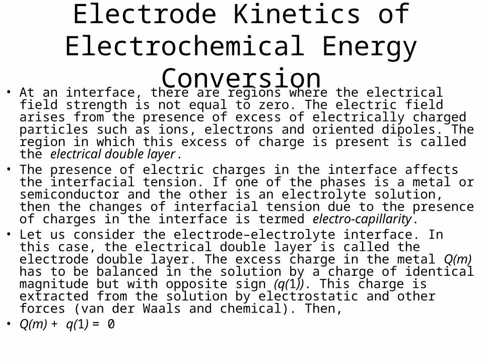
• At an interface, there are regions where the electrical field strength is not equal to zero. The electric field arises from the presence of excess of electrically charged particles such as ions, electrons and oriented dipoles. The region in which this excess of charge is present is called the electrical double layer.
• The presence of electric charges in the interface affects the interfacial tension. If one of the phases is a metal or semiconductor and the other is an electrolyte solution, then the changes of interfacial tension due to the presence of charges in the interface is termed electro-capillarity.
• Let us consider the electrode–electrolyte interface. In this case, the electrical double layer is called the electrode double layer. The excess charge in the metal Q(m) has to be balanced in the solution by a charge of identical magnitude but with opposite sign (q(1)). This charge is extracted from the solution by electrostatic and other forces (van der Waals and chemical). Then,
• Q(m) + q(1) = 0

Electrode Kinetics of Electrochemical Energy Conversion
The excess charge on the electrolyte side of the interface is dispersed perpendicular to the interface towards the bulk of the solution while that on the metallic side has, even in molecular dimensions, the properties of a plate condenser. However, in a semiconductor electrode, the excess charge on the electrode side of the interface is also dispersed.The space–charge density, (x), due to the diffuse dispersion of charge is related to q(1) by the equation
where x is the distance from the interface. The limits of this integral are determined by consideringthe electrolyte as a semi-infinite medium, with the space–charge on the solution side of the doublelayer spreading to distances, x, of the order of hundreds of Angstroms in dilute solutions. The space–charge is usually expressed in μC cm−2.
In the simple case of electrostatic attraction, the ions in the electrolyte can approach the interface to within distances given by their inner solvation sheaths so that only a monolayer of solvent molecules is situated between the atoms of the electrode and the ‘bare’ ions. The plane through the centers of ions at their minimum distance from the phase boundary is called the outer Helmholtz plane while the region between the outer Helmholtz plane and the surface of the electrode is called Helmholtz layer

• The electrostatic forces are unable to hold all the ions that form the excess charge Q(1) at the minimum distance from the phase boundary, since thermal motion continually disperses them away from the electrode. This is how the diffuse part of the double layer is formed. It is defined as that region of the double layer lying between the outer Helmholtz plane and the bulk of the solution. When only electrostatic forces are exerted on the ions the whole charge Q(1) is situated at this part of the electrode double layer. The ions can also be influenced by forces other than the coulombic forces, such as van der Waals and chemical forces which cause the so-called specific adsorption of ions.

At a given charge on the electrode, the excess charge in the solution would increase, due to specific adsorption, to a value greater than that in the metal; however, this is balanced by a change in the amount of charge in the diffuse double layer. Specific adsorption depends on the properties of the ions as well as the electrode and it is influenced also by the electrode potential. The plane through the centers of adsorbed ions is called the inner Helmholtz plane. Some ionic species (for example, ClO−4 ,NO−3 ) destroy the tetrahedral structure of water. The free energy of the solution decreases if these ions accumulate at the interface. This kind of adsorption occurs at the electrode–solution interface. In an analogous manner to ionic adsorption, the uncharged components of the solution will accumulate at the interface if they are less polar than the solvent (or if they are attracted to the metal by van der Waals or chemical forces). In case of electrode–solution interface, the adsorption of these substances is also affected by the electric field in the double layer acting on their dipoles. The substances that ccumulate at the interface due to forces other than electrostatic ones are called surface active substances or surfactants

As a basis for the derivation of the fundamental relationships between quantities characterizing the electrical double layer, it is necessary to introduce the concept of an ideal polarized electrode. The reversible electrodes are ones at a given temperature and pressure in equilibrium with the components of the solution, and their potentials are unambiguously determined by the activities of the components of the electrode and the solution. If a charge passes in an ideal reversible electrode, the subsequent processes instantly restore the original equilibrium; in this sense it is an ideal non-polarizable electrode. The ideal polarized electrode on the other hand, is capable of acquiring an electrical potential difference with respect to a reference electrode by the application of an external voltage source, and of keeping this potential difference even if the voltage source is disconnected. This potential difference will again be called the electrode potential. Like an EMFof a reversible chemical cell, it is an equilibrium quantity. In contrast to the case of a galvanic cell, the potential of an ideal polarizable electrode may be varied in an arbitrary way by changing its charge without disturbing the electrode from the equilibrium state. This electrode thus has one degree of freedom more than the electrode whose potential is determined by the composition of the solution. The ideal polarized electrode is equivalent to a perfect condenser without leakage.

• Obviously, real electrodes, whose equilibrium potentials are determined by the activities of the ions in solution, have the properties of a condenser (with leakage), since on their phase boundary with the electrolyte, an electrode double layer is also formed. However, this property can only be detected during the passage of current through the interface.
• Another definition of the ideal polarized electrode originates from the properties of a model of this electrode. On an ideal polarized electrode, either no exchange of charged particles between the electrode and the solution takes place, or, if it is thermodynamically feasible, exchange occurs only slowly, since the value of the activation energy for this process is high.

According to Grahame, a suitable example of an ideal polarized electrode is a mercury electrode in 1M potassium chloride solution. At the electrode potential – 0.556V (vs. NCE) there are several reactions possible. With regard to the reactions 2Hg Hg2+ 2 + 2e−,K+ + e− K(Hg) and 2Cl Cl2 + 2e− the equilibrium concentration of mercurous ions in solution is 10−36 mol l−1 and of potassium in the amalgam 10−45 mol l−1; the partial pressure of chlorine is 10−56 atm. Obviously, such minute quantities will not influence the electrode potential. Another possible reaction is 2H2O + 2e− → H2 + 2OH−. The corresponding equilibrium pressure of hydrogen is rather high, 1.6 × 10⁻⁵ atm, but in terms of the high overvoltage of the hydrogen evolution reaction at the mercury electrode, this reaction does not take place at all. Thus, this electrode fulfils in an excellent way the condition that the transfer of charged particles between the electrode and the electrolyte cannot occur. This is a reason for employing mercury electrode for most of the investigations in the electrode double layer studies. But in a real situation it is usually difficult to satisfy the condition that the charge on the electrode remains constant after disconnecting the external voltage. A negatively charged electrode, for example, is discharged due to the reduction of adventitious impurities such as metal ions or oxygen.
• The interfacial region in solution is the region where the value of the electrostatic potential φ, differs from that in bulk solution. The basic concept is of an ordering of positive or negative charges at the electrode surface and ordering of the opposite charge and in equal quantity in solution to neutralize the electrode charge. For electrical double layer, see the next section also.
• The function of the electrode is to supply electrons to, or remove electrons from the interface; the charge at the interface depends on applied potential.
• The proportionality constant between the applied potential and the charge due to the ordering of species in the solution interfacial region is the double layer capacity. The double layer capacity at different applied potentials can be studied by using various techniques. An often used method is the impedance technique, which is applicable to any type of electrode, solid or liquid. Another method that uses electrocapillary measurements was developed for the mercury electrode. It is only applicable to liquid electrodes, and is based on measurement of surface tension.


The principle of electrocapillary measurements was described more than a century ago by Lippmann.It is a null-point technique that counterbalances the force of gravity and surface tension, and highly accurate results can be obtained. It consists of a capillary column containing mercury upto a height ‘h’, regulated so that on altering the applied potential, the mercury–solution interface stays in the same position. Under these conditions, surface tension counterbalances the force of gravity according to the equation:2πrcγ cos θ = πr2 c ρHghg where rc is the radius of the capillary, θ is the contact angle, γ is the surface tension, and ρHg the density of mercury. The contact angle is measured with a microscope. A plot of γ vs. E is called an electrocapillary curve and has the form shown in Fig. 2.3


A variation of this method consists in using the dropping mercury electrode. The mass flux,m1, is given as,(a) Typical electrocapillary curve (plot of surface tension γ as a function of potential E)(b) Charge density on the electrode σM vs potential (obtained as the derivative of plot a)(c) Differential capacity, Cd vs potential (obtained by differentiating curve in b)

Helmholtz model (compact layer model) (1879)
• The first double layer model, due to Helmholtz, considered the ordering of positive and negative charges in a rigid fashion on both sides of the interface (double layer or compact layer), the interactions not extending any further into the solution side. This situation is similar to that of a parallel plate capacitor (Fig.). xH corresponds to the closest approach distance of the charges, point charges, that is, sum of ionic radius. The capacity would then be
• where εr is the relative permitivity (which is assumed not to vary with distance) and ε0 the permitivity of vacuum. A typical value of εr is 6–7, leading to CH = 10μFcm−2. The decay of the electrostatic potential from φM to φs is linear and CH remains constant in the applied potential.
• This model has two serious short comings:• 1. The interactions with ions in the subsequent layers to the first layer is
neglected.• 2. The dependence of electrolytic concentration on the accumulation of
charges in the double layer has not been taken into account


Gouy–Chapman model (diffuse layer model) (1910-1913)
• Gouy and Chapman independently developed a double layer model. In this model they considered that both the applied potential and electrolyte concentration influenced the value of the double layer capacity. Thus, the double layer would not be compact as in Helmholtz’s description, but of variable thickness. Since the ions are free to move (diffuse double layer) [Fig. 2.5(a)], there would be an equilibrium of the ions due to thermal and electrical fields in the double layer


Stern model (compact–diffuse layer model) (1924)Stern considered that the double layerwas formed by a compact layer of ions next to the electrode followed by a diffuse layer extending into the bulk solution. The pictorial representation is shown in Fig. 2.6. According to this theory, the total charge on the solution side is divided between the compact and diffuse layers, and is equivalent to two capacitors in series, with capacities, CH representing the compact layer and CGC representing the diffuse layer. The smaller of the two capacities determines the observed behaviour:
The total potential difference φ between the metal and the bulk of the solution drops at first in a linear fashion. φM in the metal drops till it meets xH and thereafter decays exponentially to φS in the bulk of the solution.There are two extreme cases for the variation of capacitance with potential:1. close to Ez,CH CGC and so Cd C∼ GC2. far from Ez,CH CGC and Cd ∼ CHFor concentrated electrolyte solutions, the potential drop is rapid, and hence the importance of the diffused double layer is reduced. At distance xH there is a transition from the compact to the diffuse layer. The separation plane between the two zones is called the outer Helmholtz plane (OHP).


Grahame model (triple layer model) (1947)
In spite of the fact that Stern had already distinguished between ions adsorbed on the electrode surface and those in the diffuse layer, it was Grahame17 who developed a model that is constituted by three regions. The difference between this and the Stern model is the existence of specific adsorption: a specifically adsorbed ion loses its solvation, approaching closer to the electrode surface—with strong bonding. The inner Helmholtz plane (IHP) passes through the centers of these ions. The outer Helmholtz plane (OHP) passes through the centers of the solvated and non-specifically adsorbed ions. The diffuse region is outside the OHP.In both the Stern and Grahame models, the potential varies linearly with distance upto the OHP and then exponentially in the diffuse layer

Bockris, Devanathan and Muller model (1963)More recent models of the double layer have taken into account the physical nature of the interfacial region. In dipolar solvents, such as water, it is clear that an interaction between the electrode and the dipoles must exist. This is reinforced by the fact that solvent concentration is always higher than solute concentration. For example, pure water has a concentration of 55.5 mol dm−3. The Bockris, Devanathan and Muller model recognizes this situation and shows the predominance of solvent molecules near the interface. A pictorial representation is given in Fig. 2.7. The solvent dipoles are oriented according to the charge on the electrode where they form a layer together with the specifically adsorbed ions.Regarding the electrode as a giant ion, the solvent molecules form its first solvation layer; theIHP is the plane that passes through the center of these dipoles and specifically adsorbed ions. Ina similar fashion, OHP refers to adsorption of solvated ions that could be identified with a secondsolvation layer. Outside this comes the diffuse layer. The profile of electrostatic potential variation with distance is shown in Fig. 2.7(b) and is the same in qualitative terms as in Grahame’s model


Chemical’ modelsThe concept of double layer structure is still evolving. The models developed so far emphasize electrostatic considerations. ‘Chemical’ models that have been developed take into consideration the distribution of the atoms in the electrode (especially solid electrodes) which is related to their work function. The variation of potential corresponding to the point of zero charge with the work function of the metal shows that sp metals follow a different linear relationship compared to transition metals.The first model of this kind was proposed by Damaskin and Frunkin, and based on these principles there has been a gradual evolution in the models, reviewed by Trasatti and recently by Parsons. The break in the structure of the solid causes a potential difference that begins withinthe solid itself. The interfacial region of a metal upto the IHP has been considered as an electronic molecular capacitor. This model has successfully explained many experimental results.

The first model for the structure of the double layer is analogous to a parallel plate condenser with a plane of charges on the metal and a second plane of opposite charges in the solution. According to this model, the capacity of the double layer should be independent of the potential across the metal–solution interface, which contradicts the experimentally observed behaviour.behaviour.The next model considered that the charges in the solution side are not located in one planebut diffuse into the bulk of the solution. This model yields a parabolic dependence of capacity oncharge. Though this model is satisfactory for very dilute solutions (concentration< 10−3 mol l−1), the predicted values of the capacity are far too high in concentrated solutions.A combination of the compact and diffuse layer models proved to be satisfactory. However,(1) in very dilute solutions, it became in practice identical with Helmholtz model (2) in the regionof constant capacity, the dependence of the capacity on the radius of the ion present in the solution is not seen, though the model shows this, and (3) it cannot also explain the increase in the capacity which occurs in the anodic region.

The three layer model—the metal surface, an inner Helmholtz layer that is the locus of centersof specifically adsorbed ions, and an outer Helmholtz plane that is the locus of centers of thefirst layer of hydrated ions—has several satisfactory features. However, it does not provide asatisfactory explanation for the constant capacity observed in the negative branch or the hump onthe anodic side.In all these models, the role of water was ignored, even though it is the predominant species insolution. The current accepted model is that the electrode is covered with a layer of completelyoriented water molecules. Specific adsorption of ions occurs in certain regions of potential by areplacement of some of the water molecules by the partially desolvated ions. The second layer ofwater molecules is not oriented, because these water molecules are under the influence of boththe electric field and thermal fluctuations. They are like the secondary hydration sheath around anion. Some of these water molecules can belong to the hydration sheaths of a layer of ions that arepresent in the outer Helmholtz plane. The dielectric constant of the first layer of oriented watermolecules can be taken to be 6 to 7 and that of the second—partly oriented water layer—can beabout 30 to 40. Considering the double layer as two capacitors in series, one with a low value ofε = 6 and the other a high value of ε 40, the region of constant capacity with potential may be∼understood.


Butler-Volmer Equation
• The Butler-Volmer equation is one of the most fundamental relationships in electrochemistry. It describes how the electrical current on an electrode depends on the electrode potential, considering that both a cathodic and an anodic reaction occur on the same electrode:

Butler-Volmer Equation
• where:• I = electrode current, Amps • Io= exchange current density, Amp/m2 • E = electrode potential, V • Eeq= equilibrium potential, V • A = electrode active surface area, m2 • T = absolute temperature, K • n = number of electrons involved in the electrode reaction • F = Faraday constant • R = universal gas constant • α = so-called symmetry factor or charge transfer coefficient
dimensionless The equation is named after chemists John Alfred Valentine Butler and
Max Volmer

Butler-Volmer Equation• The equation describes two regions:• At high overpotential the Butler-Volmer equation
simplifies to the Tafel equation • E − Eeq = a − blog(ic) for a cathodic reaction
• E − Eeq = a + blog(ia) for an anodic reaction
• Where:• a and b are constants (for a given reaction and
temperature) and are called the Tafel equation constants
• At low overpotential the Stern Geary equation applies

Current Voltage Curves for Electrode Reactions
Without concentration and therefore mass transport effects to complicate the electrolysis it is possible to establish the effects of voltage on the current flowing. In this situation the quantity E - Ee reflects the activation energy required to force current i to flow. Plotted below are three curves for differing values of io with α = 0.5.


Butler-Volmer Equation
• The Butler-Volmer equation is one of the most fundamental relationships in electrochemistry. It describes how the electrical current on an electrode depends on the electrode potential, considering that both a cathodic and an anodic reaction occur on the same electrode:

Butler-Volmer Equation
• where:• I = electrode current, Amps • Io= exchange current density, Amp/m2 • E = electrode potential, V • Eeq= equilibrium potential, V • A = electrode active surface area, m2 • T = absolute temperature, K • n = number of electrons involved in the electrode reaction • F = Faraday constant • R = universal gas constant • α = so-called symmetry factor or charge transfer coefficient
dimensionless The equation is named after chemists John Alfred Valentine Butler and
Max Volmer

Butler-Volmer Equation• The equation describes two regions:• At high overpotential the Butler-Volmer equation
simplifies to the Tafel equation • E − Eeq = a − blog(ic) for a cathodic reaction
• E − Eeq = a + blog(ia) for an anodic reaction
• Where:• a and b are constants (for a given reaction and
temperature) and are called the Tafel equation constants
• At low overpotential the Stern Geary equation applies

Current Voltage Curves for Electrode Reactions
Without concentration and therefore mass transport effects to complicate the electrolysis it is possible to establish the effects of voltage on the current flowing. In this situation the quantity E - Ee reflects the activation energy required to force current i to flow. Plotted below are three curves for differing values of io with α = 0.5.

Voltammetry• Although the Butler Volmer Equation predicts, that
at high overpotential, the current will increase exponentially with applied voltage, this is often not the case as the current will be influenced by mass transfer control of the reactive species.
• Take the following example of the reduction of ferric ions at a platinum rotating disc electrode (RDE).
• Fe3+ + e = Fe2+
• The rotation of the electrode establishes a well defined diffusion layer (Nernst diffusion layer)
• The contribution of the capacitance current will also be demonstrated in this example.

Effect of the Capacitance Current in Voltammetry. The reduction of Ferric Chloride is carried out in the presence of 1 M NaCl to eliminate the migration current.
Slope due to ic
Applied Potential → -Ve
Current
10-5 M Fe3+ Fe3+ + e → Fe2+
Current
10-3 M Fe3+ Fe3+ + e → Fe2+
Applied Potential → -Ve
(a)
(b)
Note that the iE curve in Fig. (a) is recorded at a much higher sensitivity than in Fig. (b).
ild
ild

Charging Current or Capacitance Current
• Note that due to the presence of the electrical double layer a charging or capacitance current is always present in voltammetric measurements.

Butler-Volmer Equation
• where:• I = electrode current, Amps • Io= exchange current density, Amp/m2 • E = electrode potential, V • Eeq= equilibrium potential, V • A = electrode active surface area, m2 • T = absolute temperature, K • n = number of electrons involved in the electrode reaction • F = Faraday constant • R = universal gas constant • α = so-called symmetry factor or charge transfer coefficient
dimensionless The equation is named after chemists John Alfred Valentine Butler and
Max Volmer

Butler Volmer Equation
• While the Butler-Volmer equation is valid over the full potential range, simpler approximate solutions can be obtained over more restricted ranges of potential. As overpotentials, either positive or negative, become larger than about 0.05 V, the second or the first term of equation becomes negligible, respectively. Hence, simple exponential relationships between current (i.e., rate) and overpotential are obtained, or the overpotential can be considered as logarithmically dependent on the current density. This theoretical result is in agreement with the experimental findings of the German physical chemist Julius Tafel (1905), and the usual plots of overpotential versus log current density are known as Tafel lines.
• The slope of a Tafel plot reveals the value of the transfer coefficient; for the given direction of the electrode reaction.

Butler-Volmer Equation
ialoverpotent cathodichigh at
exp
ialoverpotent anodichigh at
1exp
0`
0`
RT
nFii
RT
nFii
cc
aa
ia and ic are the exhange current densities for the anodic and cathodic reactions
These equations can be rearranged to give the Tafel equation which was obtained experimentally

Butler Volmer Equation - Tafel Equation
nb
in
a
iba
in
in
in
in
inF
RTi
nF
RT
o
aaa
a
ccc
c
ccc
c
059.0
ln059.0
and
log
equation Tafelknown well theisequation The
process anodic for the C25at log059.0
log059.0
process cathodic for the C25at log059.0
log059.0
lnln
00
00
0

Tafel Equation• The Tafel slope is an intensive parameter and does not
depend on the electrode surface area.• i0 is and extensive parameter and is influenced by the
electrode surface area and the kinetics or speed of the reaction.
• Notice that the Tafel slope is restricted to the number of electrons, n, involved in the charge transfer controlled reaction and the so called symmetry factor, .
• n is often = 1 and although the symmetry factor can vary between 0 and 1 it is normally close to 0.5.
• This means that the Tafel slope should be close to 120 mV if n = 1 and 60 mV if n = 2.

Tafel Equation• We can write:
iinF
RTb
iibiinF
RT
log303.2ln
slope Tafel the303.2
where
lnor ln 00

Current Voltage Curves for Electrode Reactions
Without concentration and therefore mass transport effects to complicate the electrolysis it is possible to establish the effects of voltage on the current flowing. In this situation the quantity E - Ee reflects the activation energy required to force current i to flow. Plotted below are three curves for differing values of io with α = 0.5.

Tafel Equation• The Tafel equation can be also written as:
• where• the plus sign under the exponent refers to an anodic
reaction, and a minus sign to a cathodic reaction, n is the number of electrons involved in the electrode reaction k is the rate constant for the electrode reaction, R is the universal gas constant, F is the Faraday constant. k is Boltzmann's constant, T is the absolute temperature, e is the electron charge, and α is the so called "charge transfer coefficient", the value of which must be between 0 and 1.
Tafel Equation
• The following equation was obtained experimentally
• Where:• = the over-potential• i = the current density• a and b = Tafel constants
iba log

Tafel Equation• Applicability• Where an electrochemical reaction occurs in two half reactions on
separate electrodes, the Tafel equation is applied to each electrode separately.
• The Tafel equation assumes that the reverse reaction rate is negligible compared to the forward reaction rate.
• The Tafel equation is applicable to the region where the values of polarization are high. At low values of polarization, the dependence of current on polarization is usually linear (not logarithmic):
• This linear region is called "polarization resistance" due to its formal similarity to Ohm’s law

Stern Geary Equation• Applicable in the linear region of the Butler Volmer
Equation at low over-potentials
resistanceon polarisati measured the
3.2
constant Tafel the
Where
a
a
iE
R
B
R
Bi
p
c
c
pcorr

Tafel Equation• Overview of the terms• The exchange current is the current at equilibrium,
i.e. the rate at which oxidized and reduced species transfer electrons with the electrode. In other words, the exchange current density is the rate of reaction at the reversible potential (when the overpotential is zero by definition). At the reversible potential, the reaction is in equilibrium meaning that the forward and reverse reactions progress at the same rates. This rate is the exchange current density.

Tafel Equation
• The Tafel slope is measured experimentally; however, it can be shown theoretically when the dominant reaction mechanism involves the transfer of a single electron that
• T is the absolute temperature,• R is the gas constant• α is the so called "charge transfer coefficient", the
value of which must be between 0 and 1.
F
RTb
303.2