
EVERLAST - NHProEquip.com · Operator’s Manual for PowerPlasma® Series ... Everlast is dedicated...
21
1 Rev. 1 0606-09 EVERLAST Power Plasma Series Plasma Cutters Operator ’ s Manual for PowerPlasma® Series Includes Models 50,60,60E,70,80 Safety, Setup and General Use Guide
Transcript of EVERLAST - NHProEquip.com · Operator’s Manual for PowerPlasma® Series ... Everlast is dedicated...

1
Rev. 1 0606-09
EVERLAST
Power Plasma Series
Plasma Cutters
Operator ’ s Manual for PowerPlasma® Series
Includes Models 50,60,60E,70,80
Safety, Setup and General Use Guide

2
Thank you for purchasing an everlast product. We ap-preciate your patronage and hope that you will enjoy years of use from our product. Please go directly to the Everlast website to register your unit and receive your warranty information. Your unit registration is important should any infor-mation such as product updates or recalls be issued. It is also important so that we may track your satis-faction with Everlast products and services. If you are unable to register by website, contact Everlast di-rectly through the consumer department at the main number. Your unit will be registered and warrantee will be issued and in full effect.

3
Serial number: __________________________ Model number: ____________________________ Date of Purchase___________________________
EVERLAST
Contact Information
Everlast consumer satisfaction email: [email protected]
Everlast Website: everlastwelders.com
Everlast Technical Support: [email protected]
Main toll free number: 1-877-755 WELD ( 9353 ) 9am—5pm PST M-F
11am-4pm PST Sat.
FAX: 1-650-588-8817
NOTES:
4
Table of contents
Section……………………………………………….Page General ...…………………………………………… Safety Precautions..………………………………. Introduction and Specifications………………… Know Your Machine……………………………….. 2.1 Panel Face and Functions…………………… 2.2 Lower Panel and functions….……………… Getting Started…………………………………….. 3.1 General Guidelines…………………………… 3.2 Compressor Selection……………………….. 3.3 Air Filter Installation and Selection……….. 3.5 Plasma Torches……..………………………... 3.7 Plasma Operation…….……………………….. 3.8 Helpful Hints..…….……………………………. 3.9 Gouging…………….…………………………… 3.10 Piercing………………………………………… 4.0 Troubleshooting………………………………..
5 6 9 14 14 15 1616 1616 17 17 18 19 19 20
5
Everlast is dedicated to providing you with the best possible equipment and service to meet the demanding jobs that you have. We want to go beyond deliv-ering a satisfactory product to you. That is the reason we offer technical sup-port to assist you with your needs should an occasion occur. With proper use and care your product should deliver years of trouble free service. Safe operation and proper maintenance is your responsibility. We have compiled this operator’s manual, to instruct you in basic safety, op-eration and maintenance of your Everlast product to give you the best possible experience. Much of welding and cutting is based upon experience and com-mon sense. As thorough as this welding manual may be, it is no substitute for either. Exercise extreme caution and care in all activities related to welding or cutting. Your safety, health and even life depends upon it. While accidents are never planned, preventing an accident requires careful planning. Please carefully read this manual before you operate your Everlast unit. This manual is not only for the use of the machine, but to assist in obtaining the best performance out of your unit. Do not operate the unit until you have read this manual and you are thoroughly familiar with the safe operation of the unit. If you feel you need more information please contact Everlast Support. The warranty does not cover improper use, maintenance or consumables. Do not attempt to alter or defeat any piece or part of your unit, particularly any safety device. Keep all shields and covers in place during unit operation should an unlikely failure of internal components result in the possible presence of sparks and explosions. If a failure occurs, discontinue further use until mal-functioning parts or accessories have been repaired or replaced by qualified personnel. Note on High Frequency electromagnetic disturbances: Certain welding and cutting processes generate High Frequency (HF) waves. These waves may disturb sensitive electronic equipment such as televisions, radios, computers, cell phones, and related equipment. High Frequency may also interfere with fluorescent lights. Consult with an electrician if distur-bance is noted. Sometimes, improper wire routing or poor shielding may be the cause. HF can interfere with pacemakers. See EMF warnings in following safety sec-tion for further information. Always consult your physician before entering an area known to have welding or cutting equipment if you have a pacemaker.
General
6
SAFETY PRECAUTIONS
These safety precautions are for protection of safety and health. Failure to follow these guidelines may result in serious injury or death. Be careful to read and follow all cautions and warnings. Protect yourself and others.
Welding and cutting processes produce high levels of ultraviolet (UV) radiation that can cause severe skin burn and damage. There are other potential hazards involved with welding such as severe burns and respiratory related illnesses. Therefore ob-serve the following to minimize potential accidents and injury: Use appropriate safety glasses with wrap around shields while in the work area, even under welding helmets to protect your eyes from flying sparks and debris. When chip-ping slag or grinding, goggles and face shields may be required.
When welding or cutting, always use an approved shielding device, with the correct shade of filter installed. Always use a welding helmet in good condition. Discard any broken or cracked filters or helmets. Using broken or cracked filters or helmets can cause severe eye injury and burn. Filter shades of no less than shade 5 for cutting and no less than shade 9 for welding are highly recommended. Shades greater than 9 may be required for high amperage welds. Keep filter lenses clean and clear for maxi-mum visibility. It is also advisable to consult with your eye doctor should you wear contacts for corrective vision before you wear them while welding. Do not allow personnel to watch or observe the welding or cutting operation unless fully protected by a filter screen, protective curtains or equivalent protective equip-ment. If no protection is available, exclude them from the work area. Even brief expo-sure to the rays from the welding arc can damage unprotected eyes. Always wear hearing protection because welding and cutting can be extremely noisy. Ear protection is necessary to prevent hearing loss. Even prolonged low levels of noise has been known to create long term hearing damage. Hearing protection also further protects against hot sparks and debris from entering the ear canal and doing harm. Always wear personal protective clothing. Flame proof clothing is required at all times. Sparks and hot metal can lodge in pockets, hems and cuffs. Make sure loose clothing is tucked in neatly. Leather aprons and jackets are recommended. Suitable welding jackets and coats may be purchased made from fire proof material from welding supply stores. Discard any burned or frayed clothing. Keep clothing away from oil, grease and flammable liquids. Leather boots or steel toed leather boots with rubber bottoms are required for ade-quate foot protection. Canvas, polyester and other man made materials often found in shoes will either burn or melt. Rubber or other non conductive soles are necessary to help protect from electrical shock. Flame proof and insulated gauntlet gloves are required whether welding or cutting or handling metal. Simple work gloves for the garden or chore work are not sufficient. Gauntlet type welding gloves are available from your local welding supply companies. Never attempt to weld with out gloves. Welding with out gloves can result in serious burns and electrical shock. If your hand or body parts comes into contact with the arc of a plasma cutter or welder, instant and serious burns will occur. Proper hand protection is required at all times when working with welding or cutting machines!
7
SAFETY PRECAUTIONS
continued WARNING! Persons with pacemakers should not weld, cut or be in the welding area
until they consult with their physician. Some pacemakers are sensitive to EMF radiation and could severely malfunction while welding or while being in the vicinity of someone welding. Serious injury or death may occur!
Welding and plasma cutting processes generate electro-magnetic fields and radiation. While the effects of EMF radiation are not known, it is suspected that there may be some harm from long term exposure to electromagnetic fields. Therefore, certain pre-cautions should be taken to minimize exposure:
Lay welding leads and lines neatly away from the body.
Never coil cables around the body.
Secure cables with tape if necessary to keep from the body.
Keep all cables and leads on the same side the body.
Never stand between cables or leads.
Keep as far away from the power source (welder) as possible while welding.
Never stand between the ground clamp and the torch.
Keep the ground clamp grounded as close to the weld or cut as possible. Welding and cutting processes pose certain inhalation risks. Be sure to follow any guidelines from your chosen consumable and electrode suppliers regarding possible need for respiratory equipment while welding or cutting. Always weld with adequate ventilation. Never weld in closed rooms or confined spaces. Fumes and gases re-leased while welding or cutting may be poisonous. Take precautions at all times. Any burning of the eyes, nose or throat are signs that you need to increase ventilation.
Stop immediately and relocate work if necessary until adequate ventilation is ob-tained.
Stop work completely and seek medical help if irritation and discomfort persists.
WARNING! Do not weld on galvanized steel, stainless steel, beryllium, titanium, cop-
per, cadmium, lead or zinc without proper respiratory equipment and or ventilation.
WARNING! This product when used for welding or cutting produces fumes and
gases which contains chemicals known to the State of California to cause birth de-
fects and in some cases cancer. (California Safety and Health Code §25249.5 et seq.)
WARNING! Do not weld or cut around Chlorinated solvents or degreasing areas.
Release of Phosgene gas can be deadly. Consider all chemicals to have potential deadly results if welded on or near metal containing residual amounts of chemicals. Keep all cylinders upright and chained to a wall or appropriate holding pen. Certain regulations regarding high pressure cylinders can be obtained from OSHA or local regulatory agency. Consult also with your welding supply company in your area for further recommendations. The regulatory changes are frequent so keep informed. All cylinders have a potential explosion hazard. When not in use, keep capped and closed. Store chained so that overturn is not likely. Transporting cylinders incorrectly can lead to an explosion. Do not attempt to adapt regulators to fit cylinders. Do not use faulty regulators. Do not allow cylinders to come into contact with work piece or work. Do not weld or strike arcs on cylinders. Keep cylinders away from direct heat, flame and sparks.
8
SAFETY PRECAUTIONS
continued
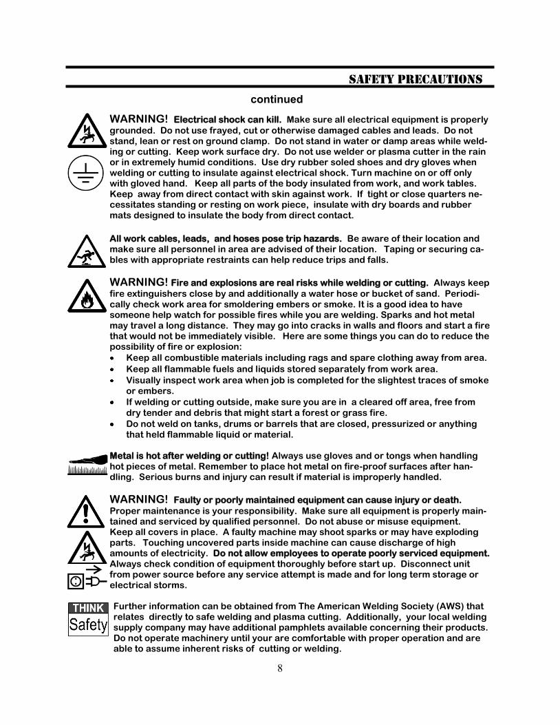
WARNING! Electrical shock can kill. Make sure all electrical equipment is properly
grounded. Do not use frayed, cut or otherwise damaged cables and leads. Do not stand, lean or rest on ground clamp. Do not stand in water or damp areas while weld-ing or cutting. Keep work surface dry. Do not use welder or plasma cutter in the rain or in extremely humid conditions. Use dry rubber soled shoes and dry gloves when welding or cutting to insulate against electrical shock. Turn machine on or off only with gloved hand. Keep all parts of the body insulated from work, and work tables. Keep away from direct contact with skin against work. If tight or close quarters ne-cessitates standing or resting on work piece, insulate with dry boards and rubber mats designed to insulate the body from direct contact.
All work cables, leads, and hoses pose trip hazards. Be aware of their location and make sure all personnel in area are advised of their location. Taping or securing ca-bles with appropriate restraints can help reduce trips and falls.
WARNING! Fire and explosions are real risks while welding or cutting. Always keep
fire extinguishers close by and additionally a water hose or bucket of sand. Periodi-cally check work area for smoldering embers or smoke. It is a good idea to have someone help watch for possible fires while you are welding. Sparks and hot metal may travel a long distance. They may go into cracks in walls and floors and start a fire that would not be immediately visible. Here are some things you can do to reduce the possibility of fire or explosion:
Keep all combustible materials including rags and spare clothing away from area.
Keep all flammable fuels and liquids stored separately from work area.
Visually inspect work area when job is completed for the slightest traces of smoke or embers.
If welding or cutting outside, make sure you are in a cleared off area, free from
dry tender and debris that might start a forest or grass fire.
Do not weld on tanks, drums or barrels that are closed, pressurized or anything that held flammable liquid or material.
Metal is hot after welding or cutting! Always use gloves and or tongs when handling hot pieces of metal. Remember to place hot metal on fire-proof surfaces after han-dling. Serious burns and injury can result if material is improperly handled.
WARNING! Faulty or poorly maintained equipment can cause injury or death.
Proper maintenance is your responsibility. Make sure all equipment is properly main-tained and serviced by qualified personnel. Do not abuse or misuse equipment. Keep all covers in place. A faulty machine may shoot sparks or may have exploding parts. Touching uncovered parts inside machine can cause discharge of high amounts of electricity. Do not allow employees to operate poorly serviced equipment. Always check condition of equipment thoroughly before start up. Disconnect unit from power source before any service attempt is made and for long term storage or electrical storms. Further information can be obtained from The American Welding Society (AWS) that relates directly to safe welding and plasma cutting. Additionally, your local welding supply company may have additional pamphlets available concerning their products. Do not operate machinery until your are comfortable with proper operation and are able to assume inherent risks of cutting or welding.
9
Introduction and Specifications Section 1
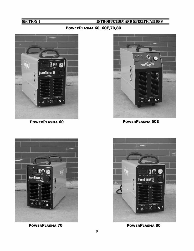
PowerPlasma 60, 60E,70,80
PowerPlasma 60 PowerPlasma 60E
PowerPlasma 70 PowerPlasma 80
10
1.1 This manual has been compiled to give an overview of operation and is designed to offer information centered around safe, practical use of the machine. It is not in-tended to teach cutting technique. All suggestions and techniques given are ap-proximations and should be used as a gen-eral guide only. 1.2 To ensure that your Everlast product is in top condition, carefully inspect unit for damage upon opening the box, looking for damage on the surface of the unit and to the machine itself and all its accessories. Do this immediately upon receipt of prod-uct. Any damage issues must be resolved right away. It is further recommended that the product be tested at the same time for proper operation, even if it is to be stored for a while. Check to make sure all pas-sages, connections and fittings are clear of any packing material or other obstruction. Record the serial number on the page pro-vided in this manual. Include purchase date for warranty reference. Serial numbers are located on the rear of the machine. 1.3 The PowerPlasma (includes 60E indus-trial) units are used daily in the industry performing day to day fabrication and re-pair activities. The exceptional arc charac-teristics are provided by the inverter based technology that employs the use of reliable IGBT transistors technology from Ger-many. Lightweight inverters allow a ma-chine to be finely tuned for precise arc characteristics, while consuming less power than the larger transformer based machines. Power Plasma units allow non-contact starts, thanks to Pilot Arc technol-ogy. The employment of the Pilot Arc sim-plifies cutting oxidized metals, expanded metals and wire meshes by providing a self energizing arc while the unit is not in close contact with the base metal. It reduces electrode fouling and allows for use in ar-eas sensitive to high frequency.
1.4 Be careful to observe duty cy-cles of the machine posted in this manual and on the machine itself.
A duty cycle is a rating of percentage of time out of 10 minutes the machine can be
used at the rated power setting . Over-heating may occur if the duty cycle is ex-ceeded. On multi-voltage, multi-phased machines, note that the rated duty cycle will change. 1.5 The unit should be stored in a dry place for long term storage. Humid/wet conditions can contribute to the eventual decay of the circuitry in the machine. For safety reasons, do not use this machine directly in the rain or with soaked clothing or protective gear. 1.6 Use only the provided handles to lift the unit. Do not suspend by cables or chains or use fork trucks to lift the units. If neces-sary, use two people to carry the unit. 1.7 Make sure that the units cooling fan and exhaust vents are kept free of obstruc-tion. Before every operation, inspect the unit for unexpected obstructions such as insect and rat nests. From time to time, a cleaning of the machine with low pressure air and a small plastic bristle brush is nec-essary to ensure long life. On these occa-sions only, unplug unit and remove cover to access interior. Concentrate efforts on aluminum heat sinks and panel vents to remove dust and dirt. 1.8 Refer to the following pages to locate your particular unit and its specifications. Note that product specifications are sub-ject to change without notice due to prod-uct improvements. If any additional infor-mation is needed contact Everlast. Sche-matics are not offered due to the proprie-tary information that they contain. How-ever, simple wiring diagrams may be ob-tained for basic diagnosis and may be ob-tained from technical support.
Introduction and Specifications Section 1
11
Introduction and Specifications Section 1
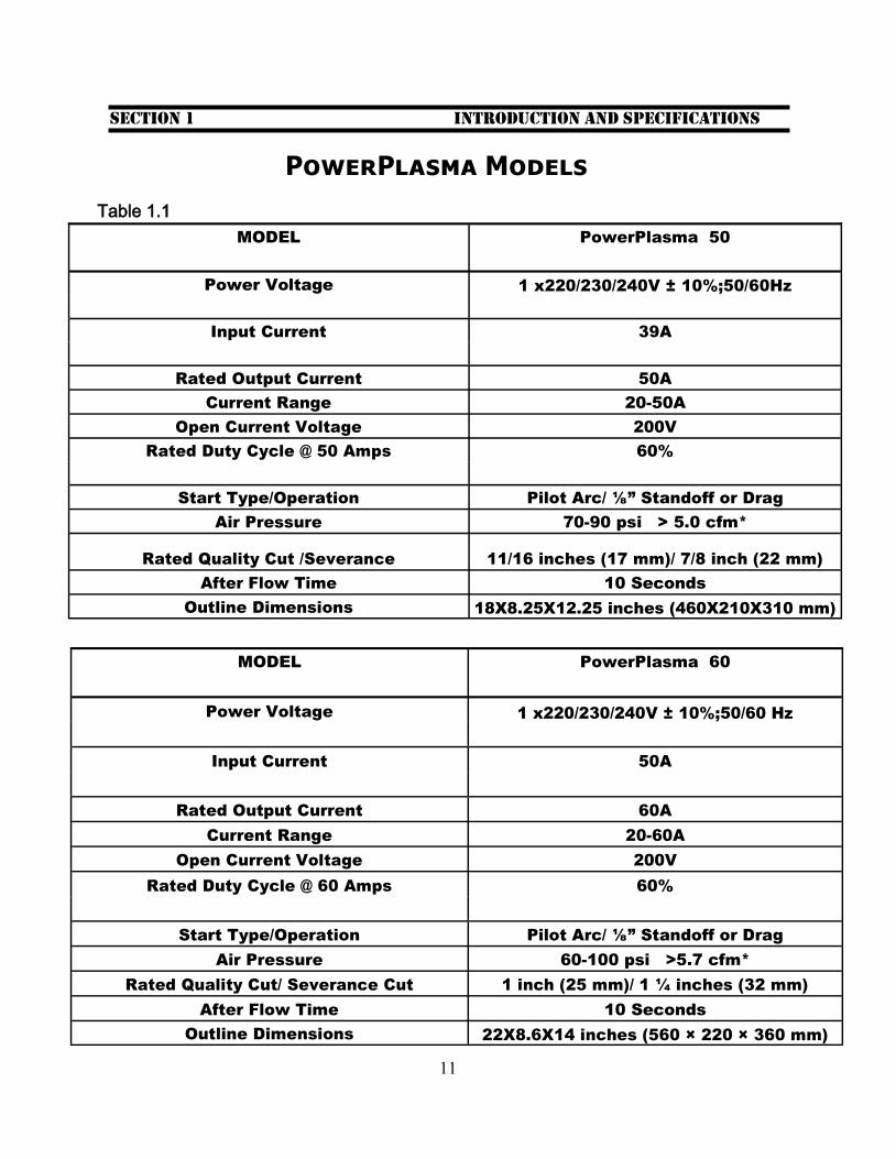
PowerPlasma Models
Table 1.1
MODEL PowerPlasma 50
Power Voltage 1 x220/230/240V ± 10%;50/60Hz
Input Current 39A
Rated Output Current 50A
Current Range 20-50A
Open Current Voltage 200V
Rated Duty Cycle @ 50 Amps 60%
Start Type/Operation Pilot Arc/ ⅛” Standoff or Drag
Air Pressure 70-90 psi > 5.0 cfm*
Rated Quality Cut /Severance 11/16 inches (17 mm)/ 7/8 inch (22 mm)
After Flow Time 10 Seconds
Outline Dimensions 18X8.25X12.25 inches (460X210X310 mm)
MODEL PowerPlasma 60
Power Voltage 1 x220/230/240V ± 10%;50/60 Hz
Input Current 50A
Rated Output Current 60A
Current Range 20-60A
Open Current Voltage 200V
Rated Duty Cycle @ 60 Amps 60%
Start Type/Operation Pilot Arc/ ⅛” Standoff or Drag
Air Pressure 60-100 psi >5.7 cfm*
Rated Quality Cut/ Severance Cut 1 inch (25 mm)/ 1 ¼ inches (32 mm)
After Flow Time 10 Seconds
Outline Dimensions 22X8.6X14 inches (560 × 220 × 360 mm)

12
Introduction and Specifications Section 1
PowerPlasma Models
MODEL PowerPlasma 70
Power Voltage 1 x220/230/240V ± 10%;50/60Hz
Input Current 58A
Rated Output Current 70A
Current Range 20-70A
Open Current Voltage 200V
Rated Duty Cycle @ 70 Amps 60%
Start Type/ Operation Pilot Arc/ ⅛” Standoff or Drag
Air Pressure 65-100 psi > 6.5 cfm*
Rated Quality Cut/ Severance Cut 1 ⅛ inches (29 mm)/ 1 ½ inches (38 mm)
After Flow Time 10 Seconds
Outline Dimensions 22X8.6X14 inches (560 × 220 × 360 mm)
MODEL
PowerPlasma 60E
(Industrial/ Large frame)
Power Voltage 3 x 220/230/240V ± 10%;50/60Hz
Input Current 28.9A
Rated Output Current 60A
Current Range 20-60A
Open Current Voltage 200V
Rated Duty Cycle 60%
Start Type/ Operation Pilot Arc/ ⅛” Standoff or Drag
Air Pressure Requirements 65 -100 psi >5.3 cfm*
Rated Quality Cut/Severance Cut 1 inch (25mm) 1 ⅜ inches (35 mm)
After Flow Time 10 Seconds
Outline Dimensions (20.5X10.25X21.25 inches) 520X260X540
13
Introduction and Specifications Section 1
PowerPlasma Models
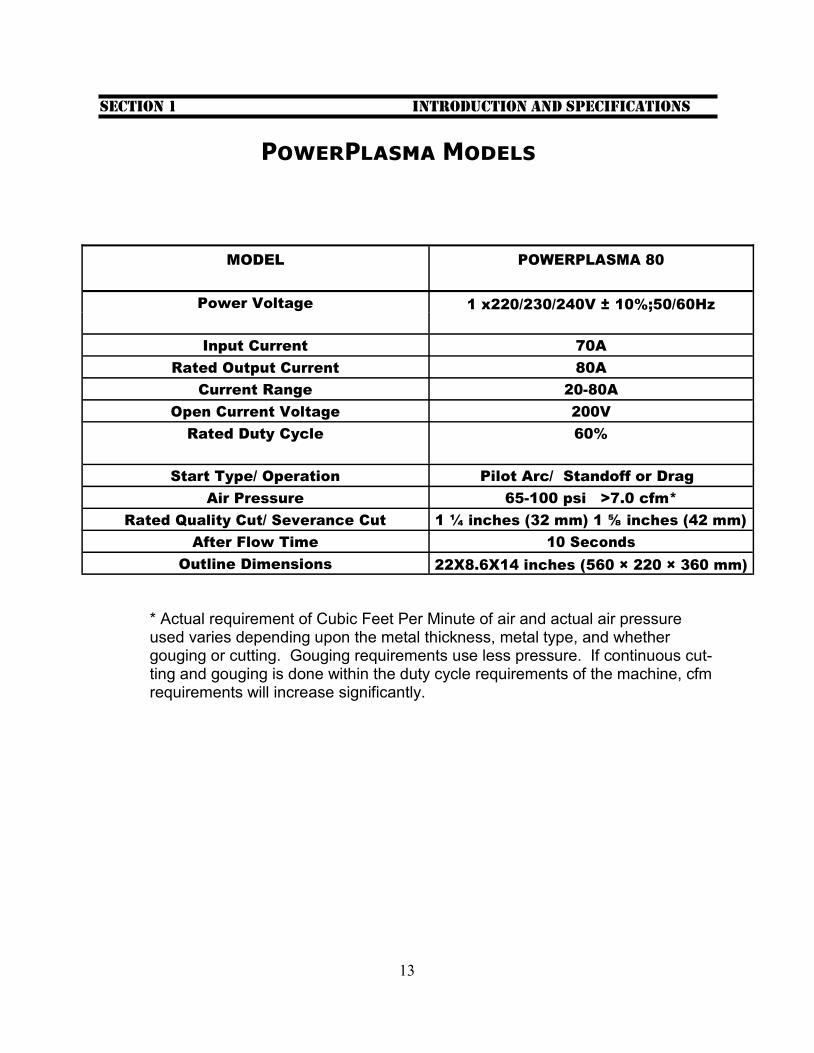
MODEL POWERPLASMA 80
Power Voltage 1 x220/230/240V ± 10%;50/60Hz
Input Current 70A
Rated Output Current 80A
Current Range 20-80A
Open Current Voltage 200V
Rated Duty Cycle 60%
Start Type/ Operation Pilot Arc/ Standoff or Drag
Air Pressure 65-100 psi >7.0 cfm*
Rated Quality Cut/ Severance Cut 1 ¼ inches (32 mm) 1 ⅝ inches (42 mm)
After Flow Time 10 Seconds
Outline Dimensions 22X8.6X14 inches (560 × 220 × 360 mm)
* Actual requirement of Cubic Feet Per Minute of air and actual air pressure used varies depending upon the metal thickness, metal type, and whether gouging or cutting. Gouging requirements use less pressure. If continuous cut-ting and gouging is done within the duty cycle requirements of the machine, cfm requirements will increase significantly.
14
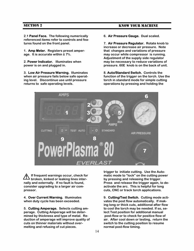
2.1 Panel Face. The following numerically referenced items refer to controls and fea-tures found on the front panel. 1. Amp Meter. Registers preset amper-age. It is accurate within ± 7%. 2. Power Indicator. Illuminates when power is on and plugged in. 3. Low Air Pressure Warning. Illuminates when air pressure fails below safe operat-ing level. Discontinue use until pressure returns to safe operating levels.
If frequent warnings occur, check for broken, kinked or leaking lines inter-
nally and externally. If no fault is found, consider upgrading to a larger air com-pressor. 4. Over Current Warning. Illuminates when duty cycle has been exceeded. 5. Cutting Amperage. Selects cutting am-perage. Cutting Amperage will be deter-mined by thickness and type of metal. Re-duction of amperage will improve quality of cuts on thinner materials without over-melting and refusing of cut pieces.
Section 2 Know Your machine
6. Air Pressure Gauge. Dual scaled. 7. Air Pressure Regulator. Rotate knob to increase or decrease air pressure. Note that changes and variations of pressure may occur while compressor is running. Adjustment of the supply side regulator may be necessary to reduce variations of pressure. 60E knob is on the back of unit. 8. Auto/Standard Switch. Controls the function of the trigger on the torch. Use the torch in standard mode for simple cutting operations by pressing and holding the
trigger to initiate cutting. Use the Auto-matic mode to “lock” on the cutting power by pressing and releasing the trigger. Press and release the trigger again, to de-activate the arc. This is helpful for long cuts, CNC or track torch applications. 9. Cutting/Test Switch. Cutting mode acti-vates the post flow automatically. If mak-ing long or thick cuts, additional after flow to cool the torch may be needed. If so, se-lect Test position for additional manual post-flow or to check for positive flow of air. After cool down or testing, return the switch to the cutting position to resume normal post-flow timing.
1
2
3
4
5
6
7
8 9
15
Section 2 Know Your machine
continued
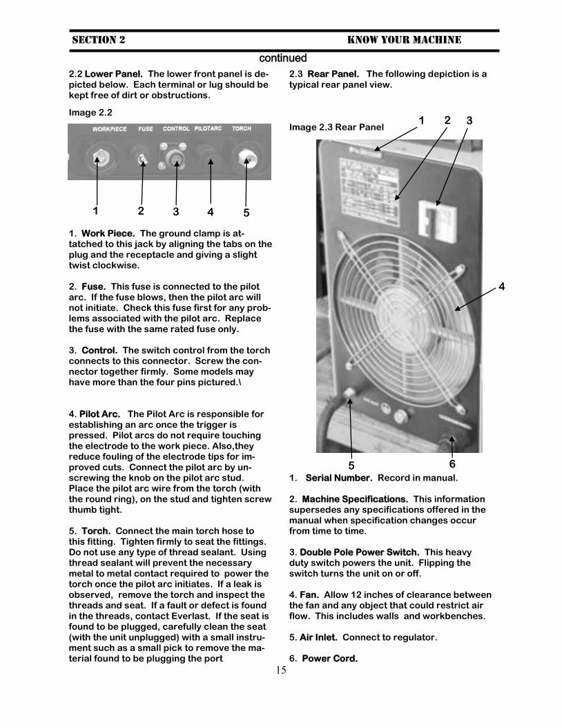
2.2 Lower Panel. The lower front panel is de-picted below. Each terminal or lug should be kept free of dirt or obstructions.
1. Work Piece. The ground clamp is at-tatched to this jack by aligning the tabs on the plug and the receptacle and giving a slight twist clockwise. 2. Fuse. This fuse is connected to the pilot arc. If the fuse blows, then the pilot arc will not initiate. Check this fuse first for any prob-lems associated with the pilot arc. Replace the fuse with the same rated fuse only. 3. Control. The switch control from the torch connects to this connector. Screw the con-nector together firmly. Some models may have more than the four pins pictured.\ 4. Pilot Arc. The Pilot Arc is responsible for establishing an arc once the trigger is pressed. Pilot arcs do not require touching the electrode to the work piece. Also,they reduce fouling of the electrode tips for im-proved cuts. Connect the pilot arc by un-screwing the knob on the pilot arc stud. Place the pilot arc wire from the torch (with the round ring), on the stud and tighten screw thumb tight. 5. Torch. Connect the main torch hose to this fitting. Tighten firmly to seat the fittings. Do not use any type of thread sealant. Using thread sealant will prevent the necessary metal to metal contact required to power the torch once the pilot arc initiates. If a leak is observed, remove the torch and inspect the threads and seat. If a fault or defect is found in the threads, contact Everlast. If the seat is found to be plugged, carefully clean the seat (with the unit unplugged) with a small instru-ment such as a small pick to remove the ma-terial found to be plugging the port
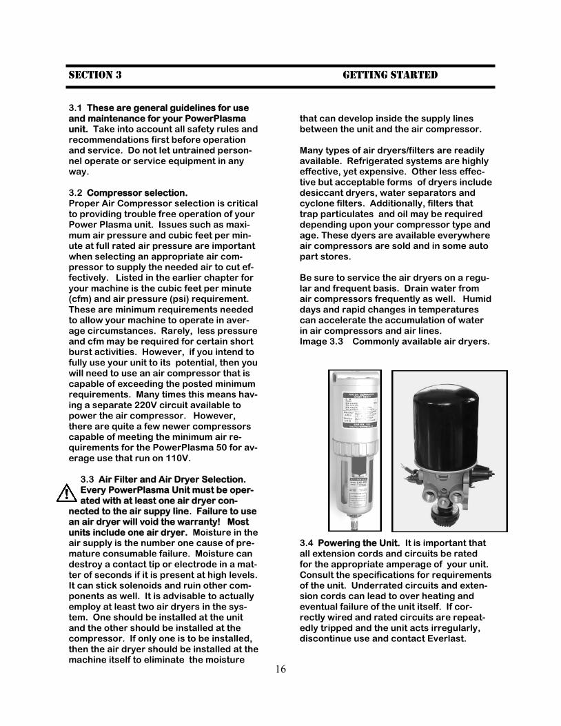
2.3 Rear Panel. The following depiction is a typical rear panel view. Image 2.3 Rear Panel 1. Serial Number. Record in manual. 2. Machine Specifications. This information supersedes any specifications offered in the manual when specification changes occur from time to time. 3. Double Pole Power Switch. This heavy duty switch powers the unit. Flipping the switch turns the unit on or off. 4. Fan. Allow 12 inches of clearance between the fan and any object that could restrict air flow. This includes walls and workbenches. 5. Air Inlet. Connect to regulator. 6. Power Cord.
1 2 3 4
1 2 3
4
5 6
Image 2.2
5
16
Section 3 Getting started
3.1 These are general guidelines for use and maintenance for your PowerPlasma unit. Take into account all safety rules and recommendations first before operation and service. Do not let untrained person-nel operate or service equipment in any way. 3.2 Compressor selection. Proper Air Compressor selection is critical to providing trouble free operation of your Power Plasma unit. Issues such as maxi-mum air pressure and cubic feet per min-ute at full rated air pressure are important when selecting an appropriate air com-pressor to supply the needed air to cut ef-fectively. Listed in the earlier chapter for your machine is the cubic feet per minute (cfm) and air pressure (psi) requirement. These are minimum requirements needed to allow your machine to operate in aver-age circumstances. Rarely, less pressure and cfm may be required for certain short burst activities. However, if you intend to fully use your unit to its potential, then you will need to use an air compressor that is capable of exceeding the posted minimum requirements. Many times this means hav-ing a separate 220V circuit available to power the air compressor. However, there are quite a few newer compressors capable of meeting the minimum air re-quirements for the PowerPlasma 50 for av-erage use that run on 110V.
3.3 Air Filter and Air Dryer Selection. Every PowerPlasma Unit must be oper-ated with at least one air dryer con-
nected to the air suppy line. Failure to use an air dryer will void the warranty! Most units include one air dryer. Moisture in the air supply is the number one cause of pre-mature consumable failure. Moisture can destroy a contact tip or electrode in a mat-ter of seconds if it is present at high levels. It can stick solenoids and ruin other com-ponents as well. It is advisable to actually employ at least two air dryers in the sys-tem. One should be installed at the unit and the other should be installed at the compressor. If only one is to be installed, then the air dryer should be installed at the machine itself to eliminate the moisture
that can develop inside the supply lines between the unit and the air compressor. Many types of air dryers/filters are readily available. Refrigerated systems are highly effective, yet expensive. Other less effec-tive but acceptable forms of dryers include desiccant dryers, water separators and cyclone filters. Additionally, filters that trap particulates and oil may be required depending upon your compressor type and age. These dyers are available everywhere air compressors are sold and in some auto part stores. Be sure to service the air dryers on a regu-lar and frequent basis. Drain water from air compressors frequently as well. Humid days and rapid changes in temperatures can accelerate the accumulation of water in air compressors and air lines. Image 3.3 Commonly available air dryers. 3.4 Powering the Unit. It is important that all extension cords and circuits be rated for the appropriate amperage of your unit. Consult the specifications for requirements of the unit. Underrated circuits and exten-sion cords can lead to over heating and eventual failure of the unit itself. If cor-rectly wired and rated circuits are repeat-edly tripped and the unit acts irregularly, discontinue use and contact Everlast.
17
Section 3 Getting started
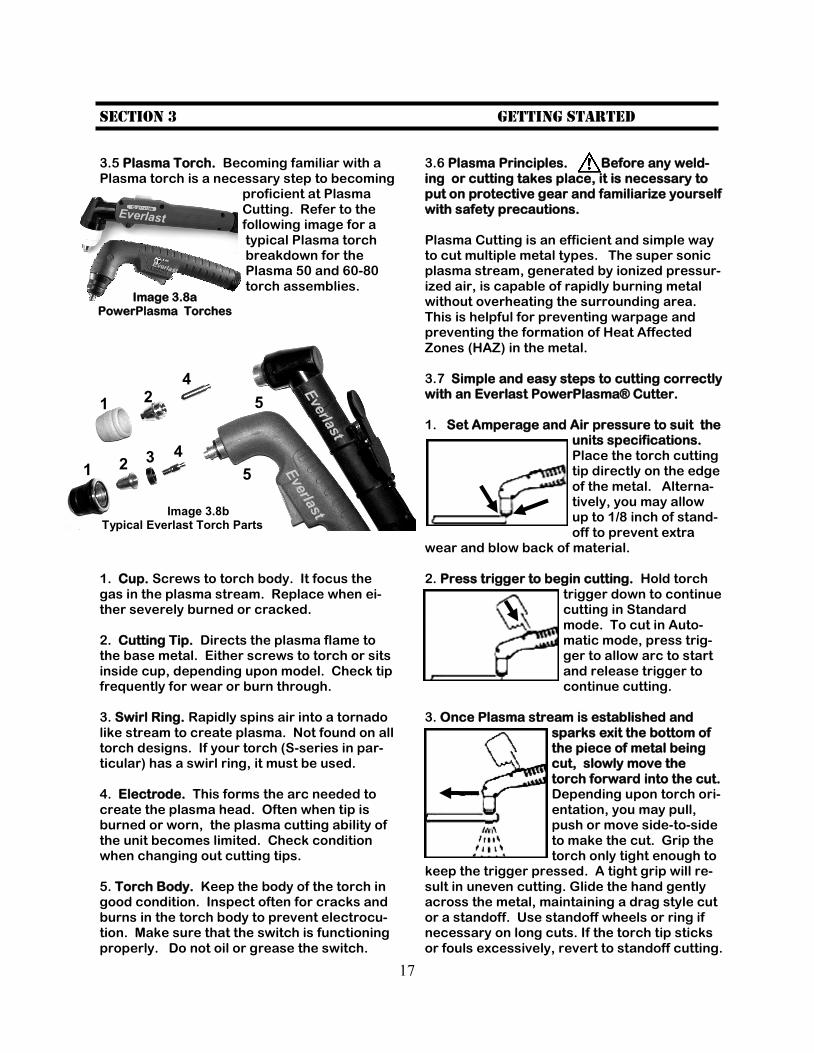
3.5 Plasma Torch. Becoming familiar with a Plasma torch is a necessary step to becoming
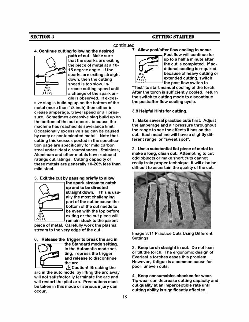
proficient at Plasma Cutting. Refer to the following image for a typical Plasma torch breakdown for the Plasma 50 and 60-80 torch assemblies.
1. Cup. Screws to torch body. It focus the gas in the plasma stream. Replace when ei-ther severely burned or cracked. 2. Cutting Tip. Directs the plasma flame to the base metal. Either screws to torch or sits inside cup, depending upon model. Check tip frequently for wear or burn through. 3. Swirl Ring. Rapidly spins air into a tornado like stream to create plasma. Not found on all torch designs. If your torch (S-series in par-ticular) has a swirl ring, it must be used. 4. Electrode. This forms the arc needed to create the plasma head. Often when tip is burned or worn, the plasma cutting ability of the unit becomes limited. Check condition when changing out cutting tips. 5. Torch Body. Keep the body of the torch in good condition. Inspect often for cracks and burns in the torch body to prevent electrocu-tion. Make sure that the switch is functioning properly. Do not oil or grease the switch.
3.6 Plasma Principles. Before any weld-ing or cutting takes place, it is necessary to put on protective gear and familiarize yourself with safety precautions. Plasma Cutting is an efficient and simple way to cut multiple metal types. The super sonic plasma stream, generated by ionized pressur-ized air, is capable of rapidly burning metal without overheating the surrounding area. This is helpful for preventing warpage and preventing the formation of Heat Affected Zones (HAZ) in the metal. 3.7 Simple and easy steps to cutting correctly with an Everlast PowerPlasma® Cutter. 1. Set Amperage and Air pressure to suit the
units specifications. Place the torch cutting tip directly on the edge of the metal. Alterna-tively, you may allow up to 1/8 inch of stand-off to prevent extra
wear and blow back of material. 2. Press trigger to begin cutting. Hold torch
trigger down to continue cutting in Standard mode. To cut in Auto-matic mode, press trig-ger to allow arc to start and release trigger to continue cutting.
3. Once Plasma stream is established and
sparks exit the bottom of the piece of metal being cut, slowly move the torch forward into the cut. Depending upon torch ori-entation, you may pull, push or move side-to-side to make the cut. Grip the torch only tight enough to
keep the trigger pressed. A tight grip will re-sult in uneven cutting. Glide the hand gently across the metal, maintaining a drag style cut or a standoff. Use standoff wheels or ring if necessary on long cuts. If the torch tip sticks or fouls excessively, revert to standoff cutting.
Image 3.8a PowerPlasma Torches
1
1
2
2
4
3 4
5
5
Image 3.8b Typical Everlast Torch Parts
Everlast
Everlast
Everlast
Everlast
18
Section 3 Getting started
continued 7. Allow post/after flow cooling to occur.
Post flow will continue for up to a half a minute after the cut is completed. If ad-ditional cooling is required because of heavy cutting or extended cutting, switch the post flow switch to
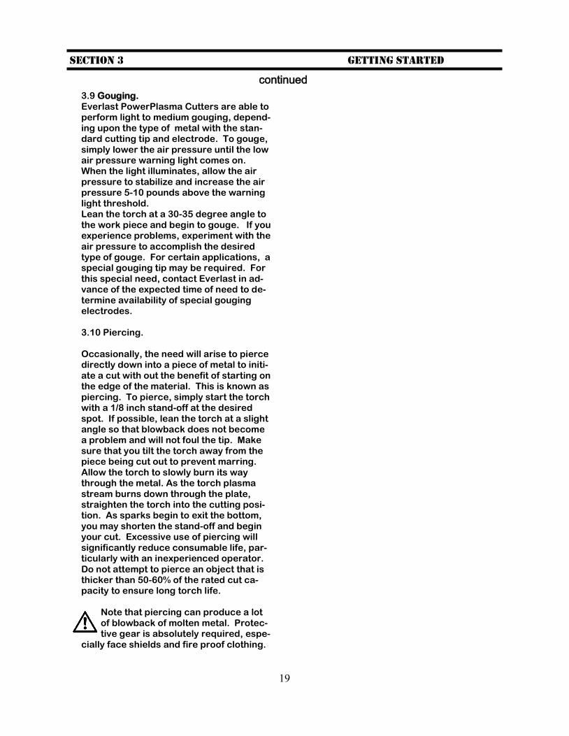
“Test” to start manual cooling of the torch. After the torch is sufficiently cooled, return the switch to cutting mode to discontinue the post/after flow cooling cycle. 3.8 Helpful Hints for cutting. 1. Make several practice cuts first. Adjust the amperage and air pressure throughout the range to see the effects it has on the cut. Each machine will have a slightly dif-ferent range or “sweet spot”. 2. Use a substantial flat piece of metal to make a long, clean cut. Attempting to cut odd objects or make short cuts cannot really train proper technique. It will also be difficult to ascertain the quality of the cut.
Image 3.11 Practice Cuts Using Different Settings. 3. Keep torch straight in cut. Do not lean or tilt the torch. The ergonomic design of Everlast’s torches eases this problem. However, fatigue is a common cause for poor, uneven cuts. 4. Keep consumables checked for wear. Tip wear can decrease cutting capacity and cut quality at an imperceptible rate until cutting ability is significantly affected.
4. Continue cutting following the desired path of cut. Make sure that the sparks are exiting the piece of metal at a 10-15 degree angle. If the sparks are exiting straight down, then the cutting speed is too slow. In-crease cutting speed until a change of the spark an-gle is observed. If exces-
sive slag is building up on the bottom of the metal (more than 1/8 inch) then either in-crease amperage, travel speed or air pres-sure. Sometimes excessive slag build up on the bottom of the cut occurs because the machine has reached its severance limit. Occasionally excessive slag can be caused by rusty or contaminated metal. Note that cutting thicknesses posted in the specifica-tion page are specifically for mild carbon steel under ideal circumstances. Stainless, Aluminum and other metals have reduced ratings cut ratings. Cutting capacity of these metals are generally 10-20% less than mild steel. 5. Exit the cut by pausing briefly to allow
the spark stream to catch up and to be directed straight down. This is usu-ally the most challenging part of the cut because the bottom of the cut needs to be even with the top before exiting or the cut piece will remain stuck to the parent
piece of metal. Carefully work the plasma stream to the very edge of the cut. 6. Release the trigger to break the arc in
the Standard mode setting. In the Automatic mode set-ting, repress the trigger and release to discontinue the arc. Caution! Breaking the
arc in the auto mode by lifting the arc away will not satisfactorily terminate the arc and will restart the pilot arc. Precautions must be taken in this mode or serious injury can occur.
Post Flow
19
Section 3 Getting started
continued
3.9 Gouging. Everlast PowerPlasma Cutters are able to perform light to medium gouging, depend-ing upon the type of metal with the stan-dard cutting tip and electrode. To gouge, simply lower the air pressure until the low air pressure warning light comes on. When the light illuminates, allow the air pressure to stabilize and increase the air pressure 5-10 pounds above the warning light threshold. Lean the torch at a 30-35 degree angle to the work piece and begin to gouge. If you experience problems, experiment with the air pressure to accomplish the desired type of gouge. For certain applications, a special gouging tip may be required. For this special need, contact Everlast in ad-vance of the expected time of need to de-termine availability of special gouging electrodes. 3.10 Piercing. Occasionally, the need will arise to pierce directly down into a piece of metal to initi-ate a cut with out the benefit of starting on the edge of the material. This is known as piercing. To pierce, simply start the torch with a 1/8 inch stand-off at the desired spot. If possible, lean the torch at a slight angle so that blowback does not become a problem and will not foul the tip. Make sure that you tilt the torch away from the piece being cut out to prevent marring. Allow the torch to slowly burn its way through the metal. As the torch plasma stream burns down through the plate, straighten the torch into the cutting posi-tion. As sparks begin to exit the bottom, you may shorten the stand-off and begin your cut. Excessive use of piercing will significantly reduce consumable life, par-ticularly with an inexperienced operator. Do not attempt to pierce an object that is thicker than 50-60% of the rated cut ca-pacity to ensure long torch life.
Note that piercing can produce a lot of blowback of molten metal. Protec-tive gear is absolutely required, espe-
cially face shields and fire proof clothing.
20
Section 4 Trouble Shooting
TROUBLE: CAUSE/SOLUTION
Machine will not turn on. Check cords and wiring. Check circuit breaker. If no fault is found, contact Everlast Support.
Machine runs, but will not cut. Check for a good ground. Make sure ground cable and PlasmaTorch is se-curely fastened to lug and receptacle. Check that the Auto/Standard switch is in the correct position for type of use de-sired (see Auto/Standard operation).
Pilot Arc will not energize. Check machine fuse. Contact Everlast Support for further remedy.
Electrodes and tips are rapidly con-sumed.
Inadequate air flow. Water in air supply. Poor cutting technique. Return to stand-off cutting of no more than 1/8 inch.
Heavy slag on the underside of the cut with complete cut through.
Travel speed too slow. Either increase cutting speed or reduce cutting amper-age to fit metal thickness. Too much standoff (more than 1/8 inch).
Cut is beveled on one side. All plasma cutters tend to leave a slightly beveled side (up to 5 degrees). However, decreasing the standoff and increasing air pressure can help reduce or eliminate problems. Always orient bevel toward parent piece so that part remains true.
Air pressure warning light illuminates while there is adequate pressure dis-playing on pressure gauge.
Internal leakage around air fittings. Though typically an easy fix, consult with Everlast Support for instructions if needed.
Cut quality is poor. Check and adjust settings. Increase/decrease air pressure. Check for con-sumable wear.
Over current LED illuminates. Duty cycle exceeded. Allow machine to cool. Make sure fan is not blocked.
Unstable Arc. Poorly grounded unit or worn electrode.
Other issues. Contact Everlast Support.

21