EVERLAST · content regarding safety, welding, or the operation/maintenance of this unit. Everlast...
21
EVERLAST POWERARC 140ST Operator’s Manual for the PowerARC 140ST Safety, Setup and General Use Guide Rev. 2 0 00618-14 Analog dc Stick/DC TIG inverter welder CC GTAW SMAW IGBT 1 ~ PHASE DC everlastwelders.com 1-877-755-9353 329 Lilefield Ave. South San Francisco, CA 94080 USA Specificaons and accessories subject to change without noce.
Transcript of EVERLAST · content regarding safety, welding, or the operation/maintenance of this unit. Everlast...

EVERLAST POWERARC 140ST
Operator’s Manual for the PowerARC 140ST Safety, Setup and General Use Guide
Rev. 2 0 00618-14
Analog dc Stick/DC TIG inverter welder
CC
GTAW
SMAW
IGBT
1 ~ PHASE
DC
everlastwelders.com
1-877-755-9353 329 Littlefield Ave. South San Francisco, CA 94080 USA
Specifications and accessories subject to change without notice.
2
Table of contents
Section…………………………………………………….Page Letter to the Customer ………………...………………. Everlast Contact Information…………………………. Safety Precautions……………………………………… Section 1: Specifications…….………………………… Section 2: General Setup and Operation…………… General Description, Purpose and Features………. Front Panel..…………………………………….………... TIG Torch and Gas Configuration……………………. Stick Configuration……………………………………... Rear Panel and Wiring…………………..……………… Arc Starting Methods (Stick)…….……..…………….. Lift TIG Arc Starting Method…….……………….……. Tungsten Preparation…………….……………………. Trouble Shooting………………………………………... Kit Contents…..………………………………………….. Notes………………………………………………………..
3 4 5 9 10 10 12 1314 15 16 17 18 19 20 21
NOTE: Product Specifications and features are subject to change without notice. Every attempt has been made to ensure this manual’s contents is accurate at time of publication. However, certain descriptions, quan-tities, appearance and specifications of the product in this manual are subject to change without notice or up-date of this manual. This manual is intended to be a general guide and not intended to be exhaustive in its content regarding safety, welding, or the operation/maintenance of this unit. Everlast Power Equipment INC. does not guarantee the accuracy, completeness, authority or authenticity of the information contained within this manual. The owner of this product assumes all liability for its use and maintenance. Everlast Power Equipment INC. does not warrant this product or this document for fitness for any particular purpose, for per-formance/accuracy or for suitability of application. Furthermore, Everlast Power Equipment INC. does not accept liability for injury or damages, consequential or incidental, resulting from the use of this product or re-
sulting from the content found in this document or accept claims by a third party of such liability.
3
Dear Customer, THANKS! You had a choice, and you bought an Everlast. We appreciate you as a customer and hope that you will enjoy years of use from your welder. Please go directly to the Everlast website to register your unit and receive your warranty infor-mation. Your unit registration is important should any information such as product updates or re-calls be issued. It is also important so that we may track your satisfaction with Everlast products and services. If you are unable to register by website, contact Everlast directly through the sales department through the main customer service number in your country. Your unit will be regis-tered and warranty will be issued and in full effect. Keep all information regarding your purchase. In the event of a problem you must contact technical support before your welder can be a candi-date for warranty service and returned.
Please review the current online warranty statement and information found on the web-site of the Everlast division located in or nearest to your country. Print it for your records and become familiar of its terms and conditions. Everlast offers full technical support, in several different forms. We have online support available through email, and a welding support forum designed for customers and noncustomer interaction. Technical advisors are active on the forum daily. We also divide our support into two divisions: technical and welding performance. Should you have an issue or question concerning your unit, please contact performance/technical support available through the main company headquarters available in your country. For best service call the appropriate support line and follow up with an email, particularly if off hours, or you cannot reach a live person. In the event you do not reach a live person, particularly during heavy call volume times, holidays, and off hours, leave a message and your call will normally be returned within 24 hours. Also for quick answers to your basic ques-tions, join the company owned forum available through the website. You’ll find knowledgeable, helpful people and staff available to answer your questions, and perhaps find a topic that already addresses your question at http://www.everlastgenerators.com/forums/. Should you need to call or write, always know your model name, purchase date and welder manu-facturing inspection date. This will assure the quick and accurate customer service. REMEMBER: Be as specific and informed as possible. Technical and performance advisors rely upon you to carefully describe the conditions and circumstances of your problem or question. Take notes of any issues as best you can. You may be asked many questions by the advisors to clarify prob-lems or issues that may seem very basic. However, diagnosis procedures MUST be followed to begin the warranty process. Advisors cannot assume anything, even with experienced users, and must cover all aspects to properly diagnose the problem. Depending upon your issue, it is advisa-ble to have basic tools handy such as screwdrivers, wrenches, pliers, and even an inexpensive test meter with volt/ohm functions before you call. Let us know how we may be of service to you should you have any questions. Sincerely, Everlast Customer Service

4
Serial number: __________________________ Model number: ____________________________ Date of Purchase___________________________
EVERLAST Contact Information
Everlast US:
Everlast consumer satisfaction email: [email protected]
Everlast Website: everlastwelders.com
Everlast Technical Support: [email protected]
Everlast Support Forum: http://www.everlastgenerators.com/forums/index.php
Main toll free number: 1-877-755 WELD ( 9353 ) 9am—5pm PST M-F
11am-4pm PST Sat.
FAX: 1-650-588-8817
Everlast Canada:
Everlast consumer satisfaction email: [email protected]
Everlast Website: everlastwelders.ca
Everlast Technical Support: [email protected]
Telephone: 905-630-8246 9am-4:30pm EST M-F
10am-1pm EST Sat.
FAX: 1-905-639-2817
Everlast Australia:
Sydney: 5A Karloo Parade Newport NSW 2106
( 0 2 ) 9999 2949
Port Macquarie: 2B Pandorea Place Port Macquarie
( 0 2 ) 6584 2037
After hours support: 0410 661 334
Everlast Technical Support: [email protected]
5
Everlast is dedicated to providing you with the best possible equipment and service to meet the demanding jobs that you have. We want to go beyond deliv-ering a satisfactory product to you. That is the reason we offer technical sup-port to assist you with your needs should an occasion occur. With proper use and care your product should deliver years of trouble free service. Safe operation and proper maintenance is your responsibility. We have compiled this operator’s manual, to instruct you in basic safety, oper-ation and maintenance of your Everlast product to give you the best possible experience. Much of welding and cutting is based upon experience and com-mon sense. As thorough as this welding manual may be, it is no substitute for either. Exercise extreme caution and care in all activities related to welding or cutting. Your safety, health and even life depends upon it. While accidents are never planned, preventing an accident requires careful planning. Please carefully read this manual before you operate your Everlast unit. This manual is not only for the use of the machine, but to assist in obtaining the best performance out of your unit. Do not operate the unit until you have read this manual and you are thoroughly familiar with the safe operation of the unit. If you feel you need more information please contact Everlast Support. The warranty does not cover improper use, maintenance or consumables. Do not attempt to alter or defeat any piece or part of your unit, particularly any safety device. Keep all shields and covers in place during unit operation should an unlikely failure of internal components result in the possible presence of sparks and explosions. If a failure occurs, discontinue further use until mal-functioning parts or accessories have been repaired or replaced by qualified personnel. Note on High Frequency electromagnetic disturbances: Certain welding and cutting processes generate High Frequency (HF) waves. These waves may disturb sensitive electronic equipment such as televisions, radios, computers, cell phones, and related equipment. High Frequency may also interfere with fluorescent lights. Consult with an electrician if disturb-ance is noted. Sometimes, improper wire routing or poor shielding may be the cause. HF can interfere with pacemakers. See EMF warnings in following safety sec-tion for further information. Always consult your physician before entering an area known to have welding or cutting equipment if you have a pacemaker.
Safety Precautions
6
SAFETY PRECAUTIONS
These safety precautions are for protection of safety and health. Failure to follow these guidelines may result in serious injury or death. Be careful to read and follow all cautions and warnings. Protect yourself and others.
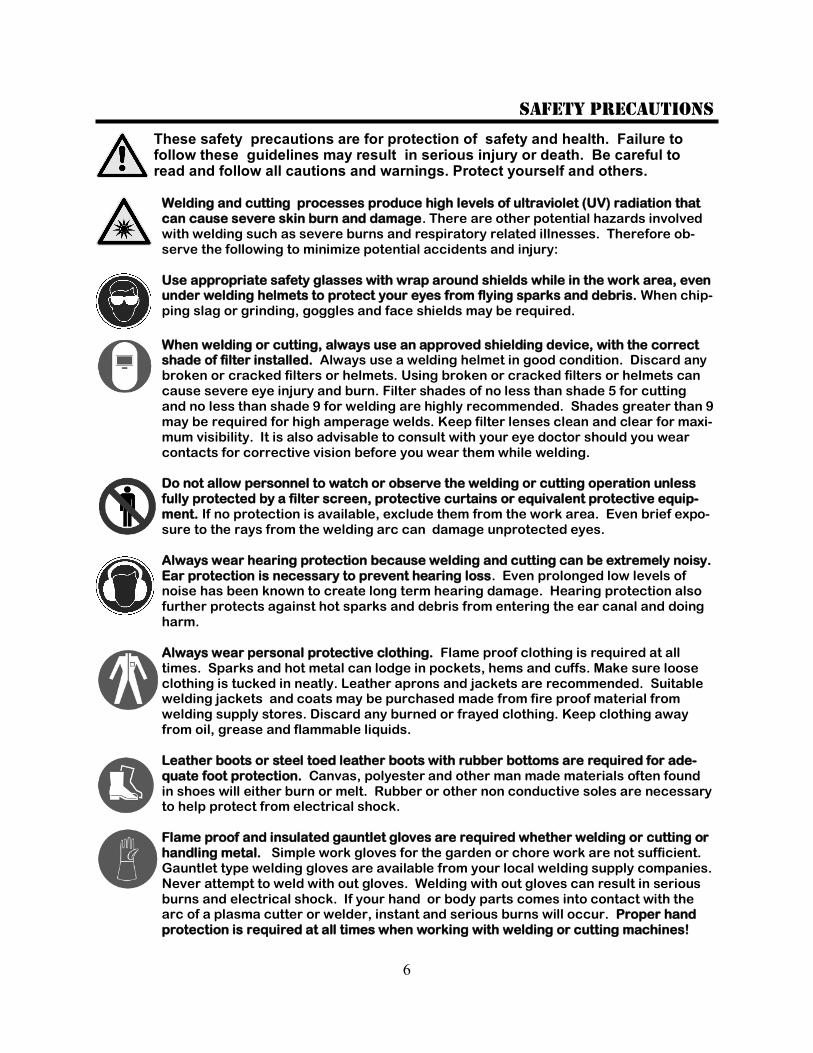
Welding and cutting processes produce high levels of ultraviolet (UV) radiation that can cause severe skin burn and damage. There are other potential hazards involved with welding such as severe burns and respiratory related illnesses. Therefore ob-serve the following to minimize potential accidents and injury: Use appropriate safety glasses with wrap around shields while in the work area, even under welding helmets to protect your eyes from flying sparks and debris. When chip-ping slag or grinding, goggles and face shields may be required.
When welding or cutting, always use an approved shielding device, with the correct shade of filter installed. Always use a welding helmet in good condition. Discard any broken or cracked filters or helmets. Using broken or cracked filters or helmets can cause severe eye injury and burn. Filter shades of no less than shade 5 for cutting and no less than shade 9 for welding are highly recommended. Shades greater than 9 may be required for high amperage welds. Keep filter lenses clean and clear for maxi-mum visibility. It is also advisable to consult with your eye doctor should you wear contacts for corrective vision before you wear them while welding. Do not allow personnel to watch or observe the welding or cutting operation unless fully protected by a filter screen, protective curtains or equivalent protective equip-ment. If no protection is available, exclude them from the work area. Even brief expo-sure to the rays from the welding arc can damage unprotected eyes. Always wear hearing protection because welding and cutting can be extremely noisy. Ear protection is necessary to prevent hearing loss. Even prolonged low levels of noise has been known to create long term hearing damage. Hearing protection also further protects against hot sparks and debris from entering the ear canal and doing harm. Always wear personal protective clothing. Flame proof clothing is required at all times. Sparks and hot metal can lodge in pockets, hems and cuffs. Make sure loose clothing is tucked in neatly. Leather aprons and jackets are recommended. Suitable welding jackets and coats may be purchased made from fire proof material from welding supply stores. Discard any burned or frayed clothing. Keep clothing away from oil, grease and flammable liquids. Leather boots or steel toed leather boots with rubber bottoms are required for ade-quate foot protection. Canvas, polyester and other man made materials often found in shoes will either burn or melt. Rubber or other non conductive soles are necessary to help protect from electrical shock. Flame proof and insulated gauntlet gloves are required whether welding or cutting or handling metal. Simple work gloves for the garden or chore work are not sufficient. Gauntlet type welding gloves are available from your local welding supply companies. Never attempt to weld with out gloves. Welding with out gloves can result in serious burns and electrical shock. If your hand or body parts comes into contact with the arc of a plasma cutter or welder, instant and serious burns will occur. Proper hand protection is required at all times when working with welding or cutting machines!

7
SAFETY PRECAUTIONS
WARNING! Persons with pacemakers should not weld, cut or be in the welding area until they consult with their physician. Some pacemakers are sensitive to EMF radiation and could severely malfunction while welding or while being in the vicinity of someone welding. Serious injury or death may occur! Welding and plasma cutting processes generate electro-magnetic fields and radiation. While the effects of EMF radiation are not known, it is suspected that there may be some harm from long term exposure to electromagnetic fields. Therefore, certain pre-cautions should be taken to minimize exposure:
Lay welding leads and lines neatly away from the body.
Never coil cables around the body.
Secure cables with tape if necessary to keep from the body.
Keep all cables and leads on the same side the body.
Never stand between cables or leads.
Keep as far away from the power source (welder) as possible while welding.
Never stand between the ground clamp and the torch.
Keep the ground clamp grounded as close to the weld or cut as possible. Welding and cutting processes pose certain inhalation risks. Be sure to follow any guidelines from your chosen consumable and electrode suppliers regarding possible need for respiratory equipment while welding or cutting. Always weld with adequate ventilation. Never weld in closed rooms or confined spaces. Fumes and gases re-leased while welding or cutting may be poisonous. Take precautions at all times. Any burning of the eyes, nose or throat are signs that you need to increase ventilation.
Stop immediately and relocate work if necessary until adequate ventilation is ob-tained.
Stop work completely and seek medical help if irritation and discomfort persists.
WARNING! Do not weld on galvanized steel, stainless steel, beryllium, titanium, cop-
per, cadmium, lead or zinc without proper respiratory equipment and or ventilation.
WARNING! This product when used for welding or cutting produces fumes and gas-
es which contains chemicals known to the State of California to cause birth defects
and in some cases cancer. (California Safety and Health Code §25249.5 et seq.)
WARNING! Do not weld or cut around Chlorinated solvents or degreasing areas.
Release of Phosgene gas can be deadly. Consider all chemicals to have potential deadly results if welded on or near metal containing residual amounts of chemicals. Keep all cylinders upright and chained to a wall or appropriate holding pen. Certain regulations regarding high pressure cylinders can be obtained from OSHA or local regulatory agency. Consult also with your welding supply company in your area for further recommendations. The regulatory changes are frequent so keep informed. All cylinders have a potential explosion hazard. When not in use, keep capped and closed. Store chained so that overturn is not likely. Transporting cylinders incorrectly can lead to an explosion. Do not attempt to adapt regulators to fit cylinders. Do not use faulty regulators. Do not allow cylinders to come into contact with work piece or work. Do not weld or strike arcs on cylinders. Keep cylinders away from direct heat, flame and sparks.
8
SAFETY PRECAUTIONS
continued
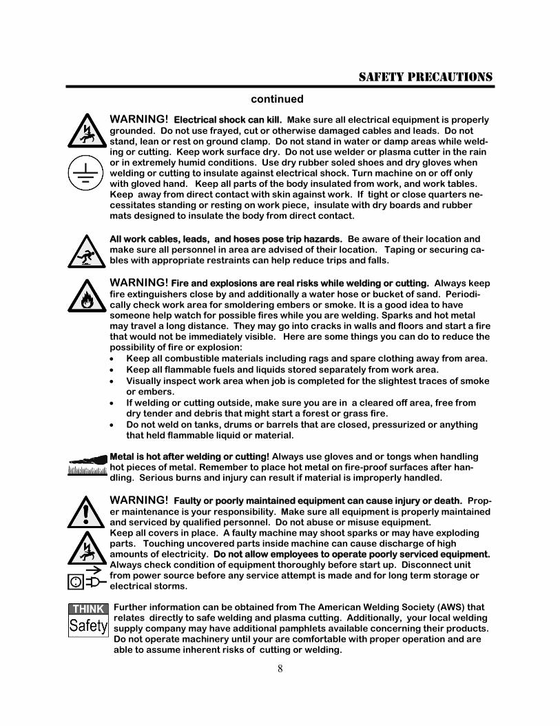
WARNING! Electrical shock can kill. Make sure all electrical equipment is properly
grounded. Do not use frayed, cut or otherwise damaged cables and leads. Do not stand, lean or rest on ground clamp. Do not stand in water or damp areas while weld-ing or cutting. Keep work surface dry. Do not use welder or plasma cutter in the rain or in extremely humid conditions. Use dry rubber soled shoes and dry gloves when welding or cutting to insulate against electrical shock. Turn machine on or off only with gloved hand. Keep all parts of the body insulated from work, and work tables. Keep away from direct contact with skin against work. If tight or close quarters ne-cessitates standing or resting on work piece, insulate with dry boards and rubber mats designed to insulate the body from direct contact.
All work cables, leads, and hoses pose trip hazards. Be aware of their location and make sure all personnel in area are advised of their location. Taping or securing ca-bles with appropriate restraints can help reduce trips and falls.
WARNING! Fire and explosions are real risks while welding or cutting. Always keep
fire extinguishers close by and additionally a water hose or bucket of sand. Periodi-cally check work area for smoldering embers or smoke. It is a good idea to have someone help watch for possible fires while you are welding. Sparks and hot metal may travel a long distance. They may go into cracks in walls and floors and start a fire that would not be immediately visible. Here are some things you can do to reduce the possibility of fire or explosion:
Keep all combustible materials including rags and spare clothing away from area.
Keep all flammable fuels and liquids stored separately from work area.
Visually inspect work area when job is completed for the slightest traces of smoke or embers.
If welding or cutting outside, make sure you are in a cleared off area, free from dry tender and debris that might start a forest or grass fire.
Do not weld on tanks, drums or barrels that are closed, pressurized or anything that held flammable liquid or material.
Metal is hot after welding or cutting! Always use gloves and or tongs when handling hot pieces of metal. Remember to place hot metal on fire-proof surfaces after han-dling. Serious burns and injury can result if material is improperly handled.
WARNING! Faulty or poorly maintained equipment can cause injury or death. Prop-
er maintenance is your responsibility. Make sure all equipment is properly maintained and serviced by qualified personnel. Do not abuse or misuse equipment. Keep all covers in place. A faulty machine may shoot sparks or may have exploding parts. Touching uncovered parts inside machine can cause discharge of high amounts of electricity. Do not allow employees to operate poorly serviced equipment. Always check condition of equipment thoroughly before start up. Disconnect unit from power source before any service attempt is made and for long term storage or electrical storms. Further information can be obtained from The American Welding Society (AWS) that relates directly to safe welding and plasma cutting. Additionally, your local welding supply company may have additional pamphlets available concerning their products. Do not operate machinery until your are comfortable with proper operation and are able to assume inherent risks of cutting or welding.
9
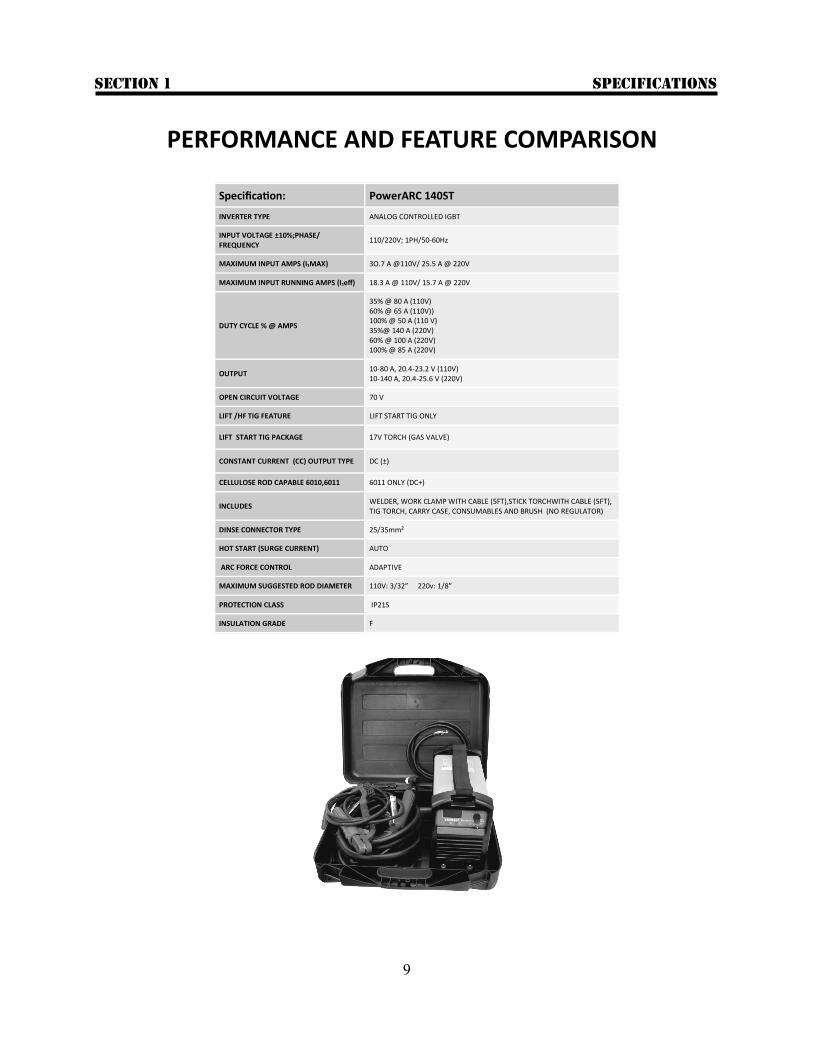
Specification: PowerARC 140ST
INVERTER TYPE ANALOG CONTROLLED IGBT
INPUT VOLTAGE ±10%;PHASE/FREQUENCY
110/220V; 1PH/50-60Hz
MAXIMUM INPUT AMPS (I₁MAX) 3O.7 A @110V/ 25.5 A @ 220V
MAXIMUM INPUT RUNNING AMPS (I₁eff) 18.3 A @ 110V/ 15.7 A @ 220V
DUTY CYCLE % @ AMPS
35% @ 80 A (110V) 60% @ 65 A (110V)) 100% @ 50 A (110 V) 35%@ 140 A (220V) 60% @ 100 A (220V) 100% @ 85 A (220V)
OUTPUT 10-80 A, 20.4-23.2 V (110V) 10-140 A, 20.4-25.6 V (220V)
OPEN CIRCUIT VOLTAGE 70 V
LIFT /HF TIG FEATURE LIFT START TIG ONLY
LIFT START TIG PACKAGE 17V TORCH (GAS VALVE)
CONSTANT CURRENT (CC) OUTPUT TYPE DC (±)
CELLULOSE ROD CAPABLE 6010,6011 6011 ONLY (DC+)
INCLUDES WELDER, WORK CLAMP WITH CABLE (5FT),STICK TORCHWITH CABLE (5FT), TIG TORCH, CARRY CASE, CONSUMABLES AND BRUSH (NO REGULATOR)
DINSE CONNECTOR TYPE 25/35mm²
HOT START (SURGE CURRENT) AUTO
ARC FORCE CONTROL ADAPTIVE
MAXIMUM SUGGESTED ROD DIAMETER 110V: 3/32” 220v: 1/8”
PROTECTION CLASS IP21S
INSULATION GRADE F
PERFORMANCE AND FEATURE COMPARISON
specifications Section 1
10
2.1 General Description, Purpose and Features. PowerARC 140 ST: The PowerARC 140ST is a compact inverter welder that provides DC stick and DC TIG welding capability. The welder is ideal for welding tasks where portability and performance are required. With 120V/240V capa-bility, the unit can be operated almost anywhere a power outlet is found, and can be used with small clean powered generators. (USA/Canada models) In stick mode the arc is smooth and stable. The auto-matic hot start in stick mode reduces rod sticking while striking an arc by providing a controlled surge of amps. Similarly, the auto arc force control adapts to the arc length and provides extra current to the arc when the arc length is shortened and voltage begins to fall. This prevents the arc from extinguishing and helps to improve overall arc performance in out of position welds. The welder is suitable for welding with iron powder, stainless and low hydrogen class rods including E7018, 6013, 7014, and 309). It also is able to weld with E6011. NOTE: This unit is not designed to weld with 6010. Additionally the unit is equipped with a lift start TIG function and is excellent for almost DC TIG application requiring less than 140 amps (240V). The lift start function provided in the TIG mode provides a clean, interference free start for electronically sensitive areas where high frequency (HF) arc starting is restricted or prohibited. (Unit does not have HF start capability.) NOTE: This unit does not support operation with a foot pedal, torch mounted amptrol or remote. NOTE: This unit is DC output only. This unit is not designed to TIG weld aluminum or magnesium. How-ever, the unit can be used to stick weld aluminum with specially designed aluminum stick welding elec-trodes (rods). Flux-coated aluminum stick welding rods are expensive and other than occasional use for emergency repair are not generally considered a eco-nomically viable alternative to AC TIG welding or MIG welding aluminum. While DC+ and DC– TIG have both been used to weld aluminum in the past, both have technical issues that can create problems. AC TIG is generally considered to be far superior, and the correct method of welding aluminum.
2.2 Basic Overview and operation. PowerARC 140ST : The PowerARC 140 ST package includes an economy 17V TIG torch with a manual gas valve, stick electrode holder with cable, and a work clamp. An optional reg-ulator may be purchased from Everlast (recommended: EV 200UW) or can be sourced from other local welding suppliers. Only pure argon (customer supplied) should be used while operating in TIG mode. TIG: NOTE: This unit is not foot pedal capable. The welder does not have a gas solenoid circuit so it does not provide automatic flow control of the gas. Rather, it’s equipped with a manually controlled valve mounted on the torch. See page 13. Twisting the valve located on the neck of the torch opens and clos-es the gas flow. This gas valve manually controls pre-flow and postflow of shielding gas , and must be opened before striking an arc. This is a common type of setup found throughout the welding industry. When using a manual gas valve setup, care must be taken to shut the gas off each time to prevent wasting argon. The torch must be connected directly to the regulator for TIG use. Most regulators come with a 5/8” CGA fitting. Some, such as the regulator available from Everlast, may be supplied without fittings or are de-signed for use with barbed fittings. You will need to join the regulator and torch by adapting the 5/16” torch gas hose to the regulator. This is easily accom-plished with a minimal amount of inert gas hose, hosebarbs or CGA fittings available at most local weld-ing supply stores. To use the TIG lift arc, flip the switch toward the TIG icon on the welder. Ensure the torch cable is located in the negative terminal of the welder and the work clamp cable is located in the positive terminal. Adjust welding current with the amp control knob to desired amp level. Make sure the tank is open and the regula-tor is adjusted for 10-20 CFH (5-10 lpm). Lightly touch the tungsten to the metal, and quickly lift up to a dis-tance of 1/8” or less. See page 17 for lift arc striking method. NOTE: the tungsten will be electrically live (hot) all the time. Do not allow it to contact the weldment or any conductive area that is directly or indirectly in
GENERAL SETUP AND OPERATION Section 2
11
contact with the work clamp or arc flashing and/or injury may result. Use a protective sleeve or torch holder to prevent accidental tungsten contact with the conductive surfaces of the work area. Stick: The stick function is fairly simple and straight forward. Be sure to flip the torch switch towards the stick icon before starting to weld, or poor performance may result. Arc striking can be done quite easily with prac-tice and the hot start reduces sticking. Be sure to dou-ble check (especially after TIG welding) that the elec-trode holder cable is located in the positive terminal, and the work clamp is located in the negative terminal. See page 16 for arc striking technique and general rod size selection. Rod size while operating on 120V volt is generally limited to 3/32” max diameter electrode. Rod size while operating on 240V is generally limited to 1/8” diameter electrode. Oversizing a rod will increase sticking and can create undesirable cold lap. 2.3 Handling and general maintenance. Duty Cycle and Overcurrent. Be careful to observe the duty cycle of the welder. Overheating may occur if the duty cycle is exceeded. Overheating will cause the unit safety cutout to en-gage, subsequently interrupting output. Allow the unit to rest while remaining switched on for 10 –15 minutes if the safety cut out has triggered. After that, reset the unit by cycling the main power switch on the rear. High heat and humid conditions will also affect the duty cycle of the welder. If the unit overheats or an overcurrent condition is experienced, the duty cycle light will light as well. Welding will resume once the duty cycle light is cleared. If the light is red, this is usu-ally indicates an over/under current condition. An over current or under current condition is usually caused by dirty power conditions, over/under voltage power sup-ply or an internal fault. If the light is green or yellow green, this a duty cycle issue. In either case, if the light does not clear and the unit does not resume welding output, by cycling the power switch (after the required amount of rest), contact technical support. Note: The duty cycle is 35% at the maximum output of 140 amps while operating on 240V. Maximum amp output will be reduced to 80(±) amps while operating on 120V to limit current draw. The Duty cycle is re-
adjusted to 35% at 80 amps while operating on 120V. The unit should be stored in a dry place for long term storage. Humid/wet conditions can contribute to the eventual decay of the circuitry in the machine. For safety reasons, do not use this machine directly in the rain or with soaked clothing or damp protective gear. The service rating for this unit is IP21S, and is not de-signed for wet environment use. Use the carry strap or handle provided to lift the welder. Do not suspend the unit in the air by the strap or handle. Make sure that the unit’s cooling fan and exhaust vents are kept free of obstruction. Before every oper-ation, inspect unit for unexpected obstructions such as insect and vermin nests. Once a month, or as needed, clean the machine thoroughly inside and out with com-pressed air. Before removing the covers however, un-plug the welder for 30 minutes to allow the internal capacitors to discharge to prevent shock, injury and even death. Afterwards, open the unit by removing the rear plastic cover and the metal cover only. Do not remove the front cover. Do not remove and circuit boards unless authorized. Check all plugs and connec-tions for tightness before replacing the covers. Do not pinch any wires when reinstalling the covers. Wear safety glasses to prevent eye injury from flying parti-cles that may get dislodged while cleaning with com-pressed air. Do not concentrate compressed air on the skin or injury may occur.
GENERAL SETUP AND OPERATION Section 2
12
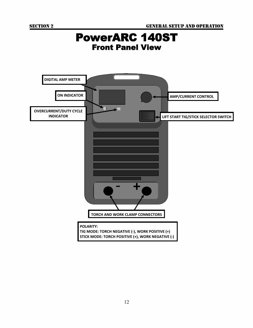
- +
DIGITAL AMP METER
AMP/CURRENT CONTROL
LIFT START TIG/STICK SELECTOR SWITCH
ON INDICATOR
OVERCURRENT/DUTY CYCLE INDICATOR
TORCH AND WORK CLAMP CONNECTORS
POLARITY: TIG MODE: TORCH NEGATIVE (-), WORK POSITIVE (+) STICK MODE: TORCH POSITIVE (+), WORK NEGATIVE (-)
PowerARC 140ST
Front Panel View
GENERAL SETUP AND OPERATION Section 2
13
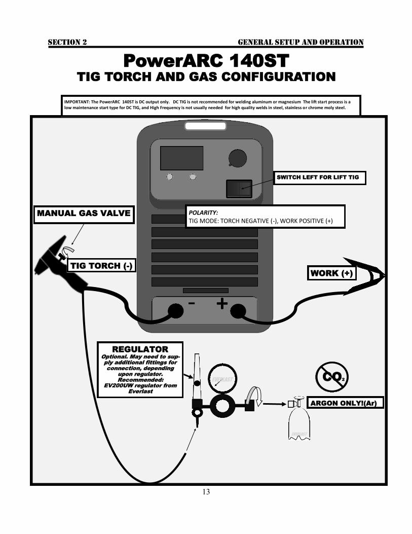
- +
POLARITY: TIG MODE: TORCH NEGATIVE (-), WORK POSITIVE (+)
ARGON ONLY!(Ar)
CO2
REGULATOR
Optional. May need to sup-
ply additional fittings for
connection, depending
upon regulator.
Recommended:
EV200UW regulator from
Everlast
EVERLAST
EVERLAST
WORK (+)
TIG TORCH (-)
IMPORTANT: The PowerARC 140ST is DC output only. DC TIG is not recommended for welding aluminum or magnesium The lift start process is a low maintenance start type for DC TIG, and High Frequency is not usually needed for high quality welds in steel, stainless or chrome moly steel.
PowerARC 140ST
TIG TORCH AND GAS CONFIGURATION
SWITCH LEFT FOR LIFT TIG
MANUAL GAS VALVE
GENERAL SETUP AND OPERATION Section 2
14
GENERAL SETUP AND OPERATION Section 2
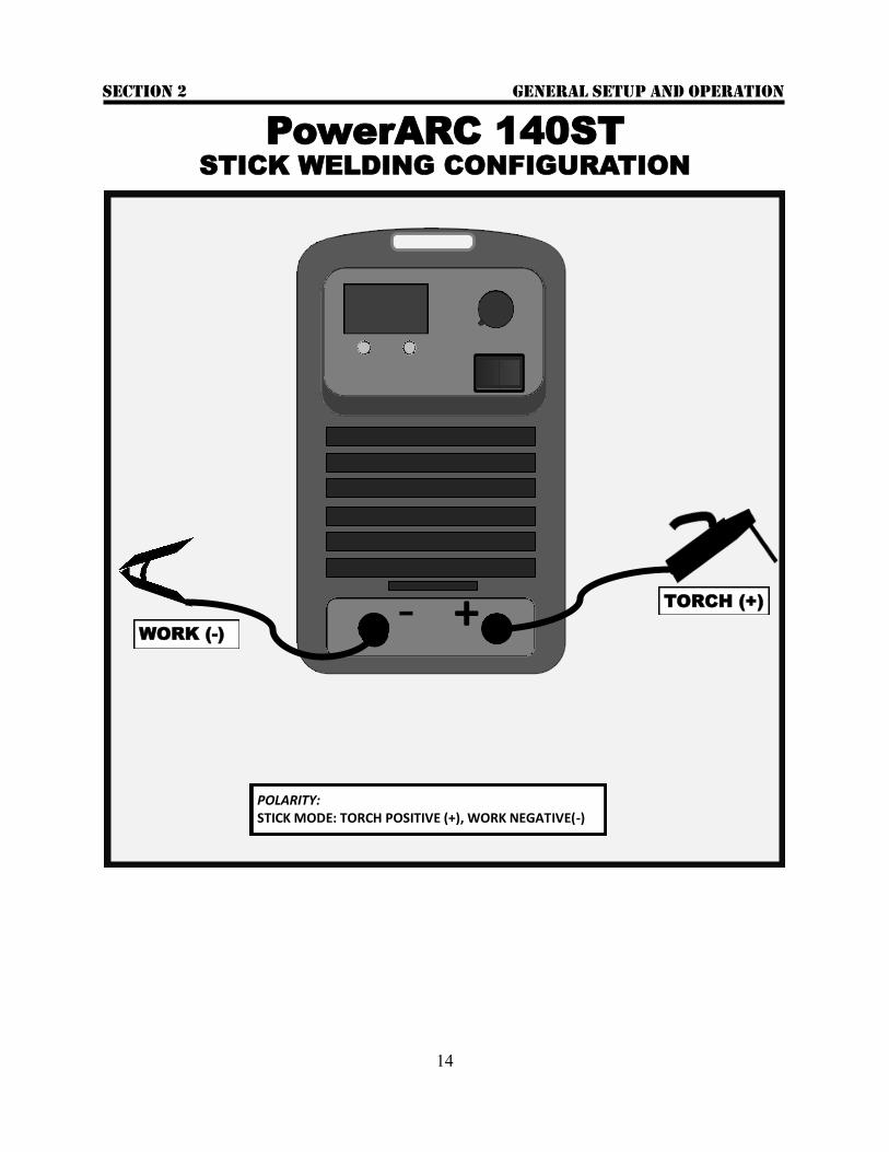
PowerARC 140ST
STICK WELDING CONFIGURATION
- +
POLARITY: STICK MODE: TORCH POSITIVE (+), WORK NEGATIVE(-)
WORK (-)
TORCH (+)

15
IMPORTANT: WHILE USING THE POWERARC 140 ST WITH 120V POWER, BE SURE TO MAINTAIN POLARITY AND USE THE WHITE WIRE AS THE COM-MON/NEUTRAL, THE BLACK AS THE HOT, AND THE GREEN AS THE GROUND OR MALFUNCTION/DAMAGE MAY OCCUR.
SWITCH ON/OFF
GREEN GROUND (120/240v)
L1,BLACK; HOT(240V)
BLACK; HOT (120V)
L2,WHITE; HOT (240V)
WHITE; NEUTRAL (120V)
50 AMP NEMA 6-50P
EVERLAST
RECEPTACLE SIDE
CONSULT A LICENSED ELECTRICIAN AND LOCAL CODES BEFORE WIRING YOUR UNIT! EVERLAST IS NOT RESPONSIBLE FOR DAMAGE OR INJURIES RESULTING FROM IMPROPER WIRING.
Use a 240V to 120V connector/adapter available from Everlast when operating with 120V power supply.
Fe, Cu
Even though the unit is grounded by the main ground wire to the chassis, an additional bonded ground may be necessary in some locations to comply with code. Con-sult a locally licensed electrician concerning the use of this ground and its application.
GENERAL SETUP AND OPERATION Section 2
PowerARC 140ST
Rear Panel View and Wiring Connection
16
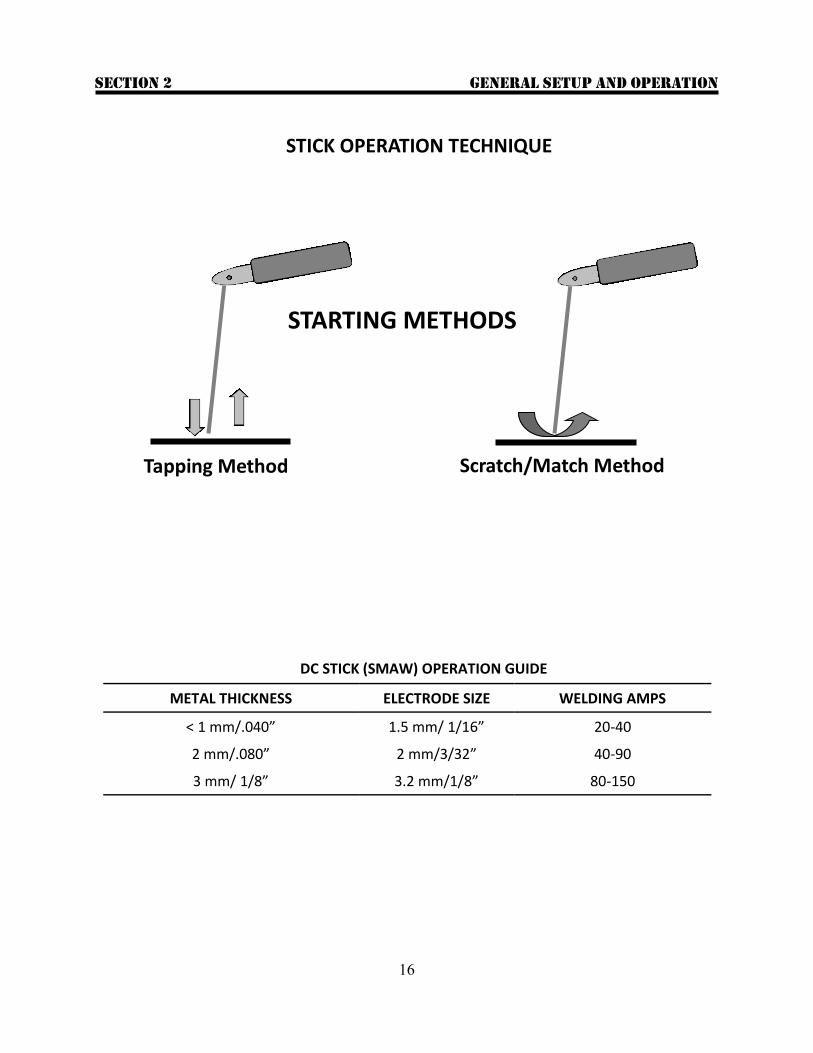
STICK OPERATION TECHNIQUE
Tapping Method Scratch/Match Method
STARTING METHODS
METAL THICKNESS ELECTRODE SIZE WELDING AMPS
< 1 mm/.040” 1.5 mm/ 1/16” 20-40
2 mm/.080” 2 mm/3/32” 40-90
3 mm/ 1/8” 3.2 mm/1/8” 80-150
DC STICK (SMAW) OPERATION GUIDE
GENERAL SETUP AND OPERATION Section 2
17
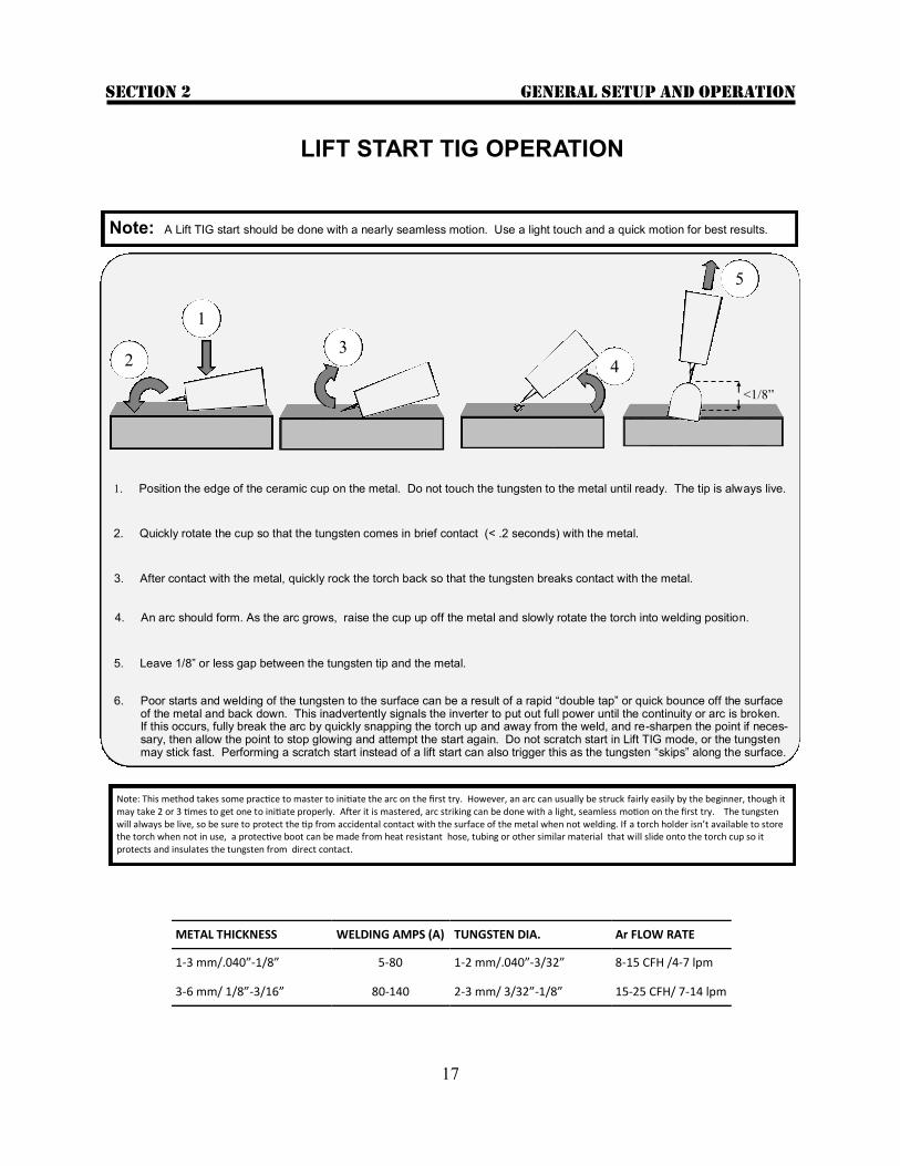
Note: This method takes some practice to master to initiate the arc on the first try. However, an arc can usually be struck fairly easily by the beginner, though it may take 2 or 3 times to get one to initiate properly. After it is mastered, arc striking can be done with a light, seamless motion on the first try. The tungsten will always be live, so be sure to protect the tip from accidental contact with the surface of the metal when not welding. If a torch holder isn’t available to store the torch when not in use, a protective boot can be made from heat resistant hose, tubing or other similar material that will slide onto the torch cup so it protects and insulates the tungsten from direct contact.
METAL THICKNESS WELDING AMPS (A) TUNGSTEN DIA. Ar FLOW RATE
1-3 mm/.040”-1/8” 5-80 1-2 mm/.040”-3/32” 8-15 CFH /4-7 lpm
3-6 mm/ 1/8”-3/16” 80-140 2-3 mm/ 3/32”-1/8” 15-25 CFH/ 7-14 lpm
5. Leave 1/8” or less gap between the tungsten tip and the metal.
1. Position the edge of the ceramic cup on the metal. Do not touch the tungsten to the metal until ready. The tip is always live.
2. Quickly rotate the cup so that the tungsten comes in brief contact (< .2 seconds) with the metal.
3. After contact with the metal, quickly rock the torch back so that the tungsten breaks contact with the metal.
<1/8”
Note: A Lift TIG start should be done with a nearly seamless motion. Use a light touch and a quick motion for best results.
1
2 3
4
5
LIFT START TIG OPERATION
4. An arc should form. As the arc grows, raise the cup up off the metal and slowly rotate the torch into welding position.
6. Poor starts and welding of the tungsten to the surface can be a result of a rapid “double tap” or quick bounce off the surface of the metal and back down. This inadvertently signals the inverter to put out full power until the continuity or arc is broken. If this occurs, fully break the arc by quickly snapping the torch up and away from the weld, and re-sharpen the point if neces-sary, then allow the point to stop glowing and attempt the start again. Do not scratch start in Lift TIG mode, or the tungsten may stick fast. Performing a scratch start instead of a lift start can also trigger this as the tungsten “skips” along the surface.
GENERAL SETUP AND OPERATION Section 2
18
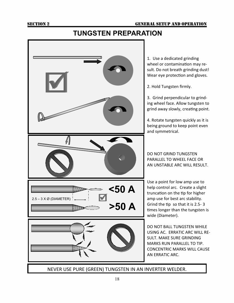
1. Use a dedicated grinding wheel or contamination may re-sult. Do not breath grinding dust! Wear eye protection and gloves. 2. Hold Tungsten firmly. 3. Grind perpendicular to grind-ing wheel face. Allow tungsten to grind away slowly, creating point. 4. Rotate tungsten quickly as it is being ground to keep point even and symmetrical. DO NOT GRIND TUNGSTEN PARALLEL TO WHEEL FACE OR AN UNSTABLE ARC WILL RESULT. Use a point for low amp use to help control arc. Create a slight truncation on the tip for higher amp use for best arc stability. Grind the tip so that it is 2.5- 3 times longer than the tungsten is wide (Diameter). DO NOT BALL TUNGSTEN WHILE USING AC. ERRATIC ARC WILL RE-SULT. MAKE SURE GRINDING MARKS RUN PARALLEL TO TIP. CONCENTRIC MARKS WILL CAUSE AN ERRATIC ARC.
<50 A
>50 A 2.5 – 3 X Ø (DIAMETER)
TUNGSTEN PREPARATION
NEVER USE PURE (GREEN) TUNGSTEN IN AN INVERTER WELDER.
GENERAL SETUP AND OPERATION Section 2
19
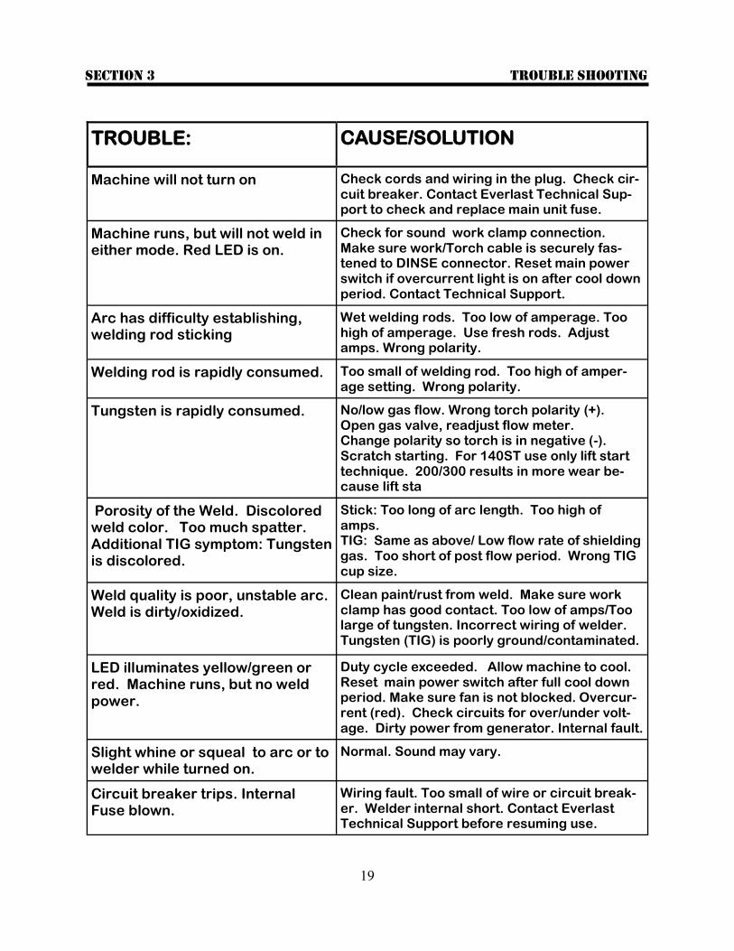
TROUBLE: CAUSE/SOLUTION
Machine will not turn on Check cords and wiring in the plug. Check cir-cuit breaker. Contact Everlast Technical Sup-port to check and replace main unit fuse.
Machine runs, but will not weld in either mode. Red LED is on.
Check for sound work clamp connection. Make sure work/Torch cable is securely fas-tened to DINSE connector. Reset main power switch if overcurrent light is on after cool down period. Contact Technical Support.
Arc has difficulty establishing, welding rod sticking
Wet welding rods. Too low of amperage. Too high of amperage. Use fresh rods. Adjust amps. Wrong polarity.
Welding rod is rapidly consumed. Too small of welding rod. Too high of amper-age setting. Wrong polarity.
Tungsten is rapidly consumed. No/low gas flow. Wrong torch polarity (+). Open gas valve, readjust flow meter. Change polarity so torch is in negative (-). Scratch starting. For 140ST use only lift start technique. 200/300 results in more wear be-cause lift sta
Porosity of the Weld. Discolored weld color. Too much spatter. Additional TIG symptom: Tungsten is discolored.
Stick: Too long of arc length. Too high of amps. TIG: Same as above/ Low flow rate of shielding gas. Too short of post flow period. Wrong TIG cup size.
Weld quality is poor, unstable arc. Weld is dirty/oxidized.
Clean paint/rust from weld. Make sure work clamp has good contact. Too low of amps/Too large of tungsten. Incorrect wiring of welder. Tungsten (TIG) is poorly ground/contaminated.
LED illuminates yellow/green or red. Machine runs, but no weld power.
Duty cycle exceeded. Allow machine to cool. Reset main power switch after full cool down period. Make sure fan is not blocked. Overcur-rent (red). Check circuits for over/under volt-age. Dirty power from generator. Internal fault.
Slight whine or squeal to arc or to welder while turned on.
Normal. Sound may vary.
Circuit breaker trips. Internal Fuse blown.
Wiring fault. Too small of wire or circuit break-er. Welder internal short. Contact Everlast Technical Support before resuming use.
Trouble shooting Section 3

20
Kit contents Section 4
PowerARC 140ST Kit Contents
Qty. Description
1 Impact resistant carry case
1 Tong style Stick electrode holder and cable, 10 ft
1 17V Economy gas valve torch and cable, 10 ft
1 Steel work clamp and cable, 10 ft
1 PowerARC 140ST DC Stick/DC TIG Inverter welder
1 Manual
NOTE: Kit contents, appearance, size and quantity are subject to change without notice.

21
NOTES: