Event Monitor Application Note...in the following hazardous environments requiring fail-safe...
24
Event Monitor Application Note 80000NT10028a Rev.6 – 2013-09-23
Transcript of Event Monitor Application Note...in the following hazardous environments requiring fail-safe...

Event Monitor Application Note 80000NT10028a Rev.6 – 2013-09-23
Event Monitor Application Note 80000NT10028a Rev.6 – 2013-09-
Reproduction forbidden without Telit Communications S.p.A. written authorization - All Rights Reserved Page 2 of 24
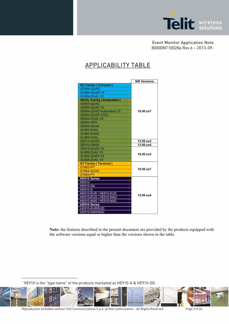
APPLICABILITY TABLE
SW Versions GC Family ( Compact )
10.00.xx7
GC864-QUAD GC864-QUAD V2 GC864-DUAL V2 GE/GL Family ( Embedded ) GE864-QUAD GE864-QUAD V2 GE864-QUAD Automotive V2 GE864-QUAD ATEX GE864-DUAL V2 GE864-GPS GE865-QUAD GL865-DUAL GL865-QUAD GL868-DUAL GE910-QUAD 13.00.xx3 GE910-GNSS 13.00.xx4 GE910-QUAD V3
16.00.xx3 GL865-DUAL V3 GL865-QUAD V3 GL868-DUAL V3 GT Family ( Terminal )
10.00.xx7 GT863-PY GT864-QUAD GT864-PY HE910 Series
12.00.xx4
HE910 1 HE910-GA HE910-D HE910-EUR / HE910-EUD HE910-EUG / HE910-NAG HE910-NAR / HE910-NAD UE910 Series UE910-EUR/EUD UE910-NAR/NAD
Note: the features described in the present document are provided by the products equipped with the software versions equal or higher than the versions shown in the table.
1 HE910 is the “type name” of the products marketed as HE910-G & HE910-DG.
Event Monitor Application Note 80000NT10028a Rev.6 – 2013-09-
Reproduction forbidden without Telit Communications S.p.A. written authorization - All Rights Reserved Page 3 of 24
SPECIFICATIONS SUBJECT TO CHANGE WITHOUT NOTICE
Notice While reasonable efforts have been made to assure the accuracy of this document, Telit assumes no liability resulting from any inaccuracies or omissions in this document, or from use of the information obtained herein. The information in this document has been carefully checked and is believed to be entirely reliable. However, no responsibility is assumed for inaccuracies or omissions. Telit reserves the right to make changes to any products described herein and reserves the right to revise this document and to make changes from time to time in content hereof with no obligation to notify any person of revisions or changes. Telit does not assume any liability arising out of the application or use of any product, software, or circuit described herein; neither does it convey license under its patent rights or the rights of others. It is possible that this publication may contain references to, or information about Telit products (machines and programs), programming, or services that are not announced in your country. Such references or information must not be construed to mean that Telit intends to announce such Telit products, programming, or services in your country.
Copyrights This instruction manual and the Telit products described in this instruction manual may be, include or describe copyrighted Telit material, such as computer programs stored in semiconductor memories or other media. Laws in the Italy and other countries preserve for Telit and its licensors certain exclusive rights for copyrighted material, including the exclusive right to copy, reproduce in any form, distribute and make derivative works of the copyrighted material. Accordingly, any copyrighted material of Telit and its licensors contained herein or in the Telit products described in this instruction manual may not be copied, reproduced, distributed, merged or modified in any manner without the express written permission of Telit. Furthermore, the purchase of Telit products shall not be deemed to grant either directly or by implication, estoppel, or otherwise, any license under the copyrights, patents or patent applications of Telit, as arises by operation of law in the sale of a product.
Computer Software Copyrights The Telit and 3rd Party supplied Software (SW) products described in this instruction manual may include copyrighted Telit and other 3rd Party supplied computer programs stored in semiconductor memories or other media. Laws in the Italy and other countries preserve for Telit and other 3rd Party supplied SW certain exclusive rights for copyrighted computer programs, including the exclusive right to copy or reproduce in any form the copyrighted computer program. Accordingly, any copyrighted Telit or other 3rd Party supplied SW computer programs contained in the Telit products described in this instruction manual may not be copied (reverse engineered) or reproduced in any manner without the express written permission of Telit or the 3rd Party SW supplier. Furthermore, the purchase of Telit products shall not be deemed to grant either directly or by implication, estoppel, or otherwise, any license under the copyrights, patents or patent applications of Telit or other 3rd Party supplied SW, except for the normal non-exclusive, royalty free license to use that arises by operation of law in the sale of a product.

Event Monitor Application Note 80000NT10028a Rev.6 – 2013-09-
Reproduction forbidden without Telit Communications S.p.A. written authorization - All Rights Reserved Page 4 of 24
Usage and Disclosure Restrictions License Agreements The software described in this document is the property of Telit and its licensors. It is furnished by express license agreement only and may be used only in accordance with the terms of such an agreement. Copyrighted Materials Software and documentation are copyrighted materials. Making unauthorized copies is prohibited by law. No part of the software or documentation may be reproduced, transmitted, transcribed, stored in a retrieval system, or translated into any language or computer language, in any form or by any means, without prior written permission of Telit High Risk Materials Components, units, or third-party products used in the product described herein are NOT fault-tolerant and are NOT designed, manufactured, or intended for use as on-line control equipment in the following hazardous environments requiring fail-safe controls: the operation of Nuclear Facilities, Aircraft Navigation or Aircraft Communication Systems, Air Traffic Control, Life Support, or Weapons Systems (High Risk Activities"). Telit and its supplier(s) specifically disclaim any expressed or implied warranty of fitness for such High Risk Activities.
Trademarks TELIT and the Stylized T Logo are registered in Trademark Office. All other product or service names are the property of their respective owners. Copyright © Telit Communications S.p.A.
Event Monitor Application Note 80000NT10028a Rev.6 – 2013-09-
Reproduction forbidden without Telit Communications S.p.A. written authorization - All Rights Reserved Page 5 of 24
Contents
1. INTRODUCTION ....................................................................................................................... 6
1.1. SCOPE ............................................................................................................................................. 6 1.2. AUDIENCE ........................................................................................................................................ 6 1.3. CONTACT INFORMATION, SUPPORT ..................................................................................................... 6 1.4. TEXT CONVENTIONS .......................................................................................................................... 6 1.5. RELATED DOCUMENTS ...................................................................................................................... 7 1.6. DOCUMENT HISTORY ......................................................................................................................... 7
2. EVENT MONITOR SERVICE ...................................................................................................... 8
2.1. PRELIMINARY EVENT MONITOR SETTING ............................................................................................. 8 2.1.1. Battery Voltage Drop ......................................................................................................................... 10 2.1.2. DTR Signal Status.............................................................................................................................. 11 2.1.3. Network Roaming State .................................................................................................................... 12 2.1.4. GPRS Context Deactivation ............................................................................................................... 13 2.1.5. Call Rings Number ............................................................................................................................ 14 2.1.6. Module Start-Up ................................................................................................................................ 16 2.1.7. Network Registration ........................................................................................................................ 17 2.1.8. GPIO Pin Status Monitoring .............................................................................................................. 18 2.1.9. ADC Pin Exceeds Voltage Threshold ................................................................................................ 19 2.1.10. ADC Pin Drops Below Voltage Threshold ......................................................................................... 20 2.1.11. DTMF String Monitoring .................................................................................................................... 22
3. ABBREVIATION AND ACRONYMS .......................................................................................... 24
Tables Tab. 1: Events provided by the Telit’s Modules ........................................................................................... 9
Event Monitor Application Note 80000NT10028a Rev.6 – 2013-09-
Reproduction forbidden without Telit Communications S.p.A. written authorization - All Rights Reserved Page 6 of 24
1. Introduction
1.1. Scope Scope of the document is to give to the reader a guideline to configure the EVENT MONITOR Service provided by the Telit’s modules.
1.2. Audience The present note is intended for people that need to develop applications based on the recognition of events provided by the EVENT MONITOR Service.
1.3. Contact Information, Support For general contact, technical support, to report documentation errors and to order manuals, contact Telit Technical Support Center (TTSC) at:
[email protected] [email protected] [email protected] [email protected]
Alternatively, use:
http://www.telit.com/en/products/technical-support-center/contact.php For detailed information about where you can buy the Telit modules or for recommendations on accessories and components visit:
http://www.telit.com To register for product news and announcements or for product questions contact Telit Technical Support Center (TTSC). Our aim is to make this guide as helpful as possible. Keep us informed of your comments and suggestions for improvements. Telit appreciates feedback from the users of our information.
1.4. Text Conventions Danger – This information MUST be followed or catastrophic equipment failure or bodily injury may occur. Caution or Warning – Alerts the user to important points about integrating the module, if these points are not followed, the module and end user equipment may fail or malfunction.
Event Monitor Application Note 80000NT10028a Rev.6 – 2013-09-
Reproduction forbidden without Telit Communications S.p.A. written authorization - All Rights Reserved Page 7 of 24
Tip or Information – Provides advice and suggestions that may be useful when integrating the module. All dates are in ISO 8601 format, i.e. YYYY-MM-DD.
1.5. Related Documents [1] AT Commands Reference Guide, Telit document: 80000ST10025a [2] HE910 AT Commands Reference Guide, Telit document: 80378ST10091A [3] Virtual Serial Device, Application Note, Telit document: 80000NT10045A [4] HE910 Family Ports Arrangements, User Guide, Telit document 1vv0300971 [5] Telit Modules Software User Guide, Telit document: 1vv0300784
1.6. Document History RReevviissiioonn DDaattee CChhaannggeess ISSUE#0 2009-08-28 Release First ISSUE# 0 ISSUE #1 2010-05-07 Added note on alerts section
Added note regarding STARTUP event on alerts section ISSUE#2 2010-10-04 Added GL865-DUAL to the applicability table ISSUE#3 2012-10-08 General review of the document in accordance with the addition
of the products: HE910, GE910. ISSUE#4 2013-02-15 Updated Applicability Table, removed: GM862-GPS, GE863-GPS,
and GE863-PRO; added: GL865-DUAL V3, GL868-DUAL V3 Added chapter: DTMF String Monitoring, and Abbreviation and acronyms. Removed chapter: Requirements. Reorganized the entire document.
ISSUE#5 2013-04-16 Updated Applicability Table: software version 12.00.xx3 12.00.xx4, and added GL868-DUAL V3.
ISSUE#6 2013-09-23 Updated Applicability Table: added UE910 series sw version 12.00.xx4, GE910-GNSS sw version 13.00.xx4, GL865-QUAD V3 sw version 16.00xx3, GE910-QUAD V3 sw version 16.00xx3

Event Monitor Application Note 80000NT10028a Rev.6 – 2013-09-
Reproduction forbidden without Telit Communications S.p.A. written authorization - All Rights Reserved Page 8 of 24
2. Event Monitor Service The Telit’s modules provide the EVENT MONITOR service allowing the user to associate the execution of one or more AT command in accordance with the occurrence of a specified and configured event monitored by the module itself.
Warning: to have more information about the syntax and parameters of the AT commands described in the next pages refer to the document [1], or [2] according to the specific module that you are using.
2.1. Preliminary Event Monitor Setting Using the following AT command, the service is configured to run on the third AT instance (see later in this chapter the concept of instance), the #EVMONI: <AT Command(s)> URC is enabled and the maximum timeout for the AT commands execution (triggered by the event) is set to 2 minutes: AT#ENAEVMONICFG=3,1,2
Warning: usefulness of the timeout. The AT commands that force the module in online mode connection (like #SD, #FTPGET, #FTPPUT, etc) should be avoided because they cause a block of the #EVMONI execution. After the expiration of the timeout, set via AT#ENAEVMONICFG command, the module reboots.
Enter the following command to enable the EVENT MONITOR service. AT#ENAEVMONI=1 Using the AT#EVMONI command described in the next chapters, it is possible to monitor the specific events summarized in the table below.
<label> identifying the Event Events Description
VBATT Battery voltage
DTR DTR signal status
ROAM Network roaming state
CONTDEACT GPRS context deactivation
RING Call rings number
STARTUP Module start-up
REGISTERED Network registration (to home network or in roaming) GPIOx (x = 1,2,3,4,5) GPIO pin status monitoring
Event Monitor Application Note 80000NT10028a Rev.6 – 2013-09-
Reproduction forbidden without Telit Communications S.p.A. written authorization - All Rights Reserved Page 9 of 24
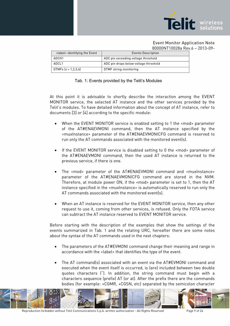
<label> identifying the Event Events Description
ADCH1 ADC pin exceeding voltage threshold
ADCL1 ADC pin drops below voltage threshold
DTMFx (x = 1,2,3,4) DTMF string monitoring
Tab. 1: Events provided by the Telit’s Modules
At this point it is advisable to shortly describe the interaction among the EVENT MONITOR service, the selected AT instance and the other services provided by the Telit’s modules. To have detailed information about the concept of AT instance, refer to documents [3] or [4] according to the specific module:
• When the EVENT MONITOR service is enabled setting to 1 the <mod> parameter of the AT#ENAEVMONI command, then the AT instance specified by the <muxInstance> parameter of the AT#ENAEVMONICFG command is reserved to run only the AT commands associated with the monitored event(s).
• If the EVENT MONITOR service is disabled setting to 0 the <mod> parameter of
the AT#ENAEVMONI command, then the used AT instance is returned to the previous service, if there is one.
• The <mod> parameter of the AT#ENAEVMONI command and <muxInstance>
parameter of the AT#ENAEVMONICFG command are stored in the NVM. Therefore, at module power ON, if the <mod> parameter is set to 1, then the AT instance specified in the <muxInstance> is automatically reserved to run only the AT commands associated with the monitored event(s).
• When an AT instance is reserved for the EVENT MONITOR service, then any other
request to use it, coming from other services, is refused. Only the FOTA service can subtract the AT instance reserved to EVENT MONITOR service.
Before starting with the description of the examples that show the settings of the events summarized in Tab. 1 and the relating URC, hereafter there are some notes about the syntax of the AT commands used in the next chapters:
• The parameters of the AT#EVMONI command change their meaning and range in accordance with the <label> that identifies the type of the event.
• The AT command(s) associated with an event via the AT#EVMONI command and
executed when the event itself is occurred, is (are) included between two double quotes characters (“). In addition, the string command must begin with a characters sequence (prefix) AT (or at). After the prefix there are the commands bodies (for example: +CGMR, +CGSN, etc) separated by the semicolon character
Event Monitor Application Note 80000NT10028a Rev.6 – 2013-09-
Reproduction forbidden without Telit Communications S.p.A. written authorization - All Rights Reserved Page 10 of 24
(;) if the extended commands syntax 2 is used. The maximum number of characters included between the two double quotes is 96. If the command string contains a double quotes (“) character, then it must be replaced with the following three characters \22.
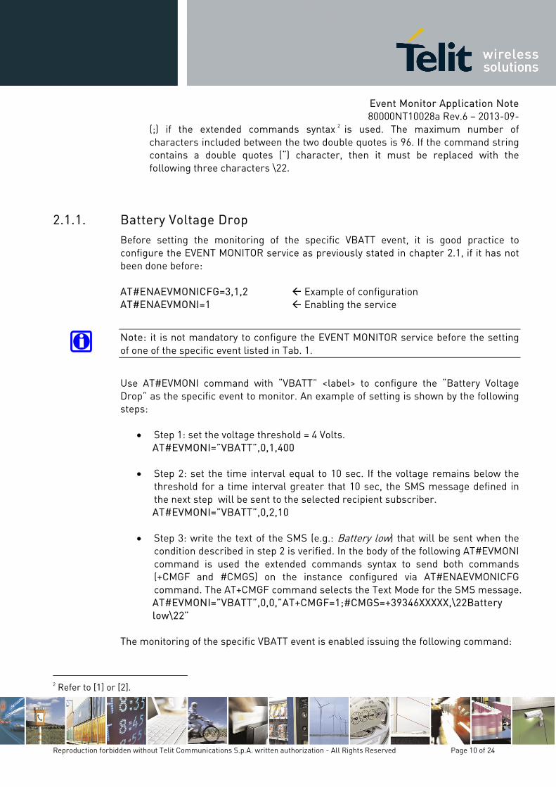
2.1.1. Battery Voltage Drop Before setting the monitoring of the specific VBATT event, it is good practice to configure the EVENT MONITOR service as previously stated in chapter 2.1, if it has not been done before: AT#ENAEVMONICFG=3,1,2 Example of configuration AT#ENAEVMONI=1 Enabling the service
Note: it is not mandatory to configure the EVENT MONITOR service before the setting of one of the specific event listed in Tab. 1.
Use AT#EVMONI command with “VBATT” <label> to configure the “Battery Voltage Drop” as the specific event to monitor. An example of setting is shown by the following steps:
• Step 1: set the voltage threshold = 4 Volts. AT#EVMONI=”VBATT”,0,1,400
• Step 2: set the time interval equal to 10 sec. If the voltage remains below the
threshold for a time interval greater that 10 sec, the SMS message defined in the next step will be sent to the selected recipient subscriber. AT#EVMONI=”VBATT”,0,2,10
• Step 3: write the text of the SMS (e.g.: Battery low) that will be sent when the
condition described in step 2 is verified. In the body of the following AT#EVMONI command is used the extended commands syntax to send both commands (+CMGF and #CMGS) on the instance configured via AT#ENAEVMONICFG command. The AT+CMGF command selects the Text Mode for the SMS message. AT#EVMONI=”VBATT”,0,0,”AT+CMGF=1;#CMGS=+39346XXXXX,\22Battery low\22”
The monitoring of the specific VBATT event is enabled issuing the following command:
2 Refer to [1] or [2].
Event Monitor Application Note 80000NT10028a Rev.6 – 2013-09-
Reproduction forbidden without Telit Communications S.p.A. written authorization - All Rights Reserved Page 11 of 24
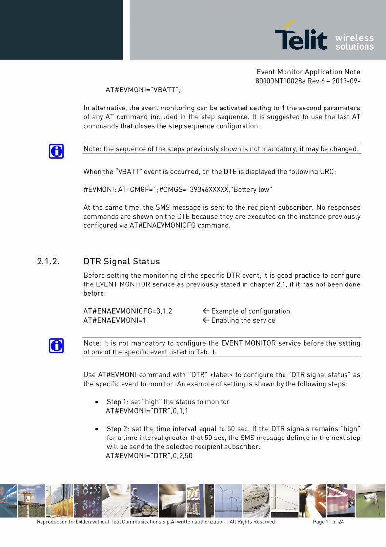
AT#EVMONI=”VBATT”,1 In alternative, the event monitoring can be activated setting to 1 the second parameters of any AT command included in the step sequence. It is suggested to use the last AT commands that closes the step sequence configuration.
Note: the sequence of the steps previously shown is not mandatory, it may be changed.
When the “VBATT” event is occurred, on the DTE is displayed the following URC: #EVMONI: AT+CMGF=1;#CMGS=+39346XXXXX,"Battery low" At the same time, the SMS message is sent to the recipient subscriber. No responses commands are shown on the DTE because they are executed on the instance previously configured via AT#ENAEVMONICFG command.
2.1.2. DTR Signal Status Before setting the monitoring of the specific DTR event, it is good practice to configure the EVENT MONITOR service as previously stated in chapter 2.1, if it has not been done before: AT#ENAEVMONICFG=3,1,2 Example of configuration AT#ENAEVMONI=1 Enabling the service
Note: it is not mandatory to configure the EVENT MONITOR service before the setting of one of the specific event listed in Tab. 1.
Use AT#EVMONI command with “DTR” <label> to configure the “DTR signal status” as the specific event to monitor. An example of setting is shown by the following steps:
• Step 1: set “high” the status to monitor AT#EVMONI=”DTR”,0,1,1
• Step 2: set the time interval equal to 50 sec. If the DTR signals remains “high” for a time interval greater that 50 sec, the SMS message defined in the next step will be send to the selected recipient subscriber. AT#EVMONI=”DTR”,0,2,50
Event Monitor Application Note 80000NT10028a Rev.6 – 2013-09-
Reproduction forbidden without Telit Communications S.p.A. written authorization - All Rights Reserved Page 12 of 24
• Step 3: write the text of the SMS (e.g. DTR high) that will be sent when the condition described in step 2 is verified. In the body of the following AT#EVMONI command is used the extended commands syntax to send both commands (+CMGF and #CMGS) on the instance configured via AT#ENAEVMONICFG command. The AT+CMGF command selects the Text Mode for the SMS message. AT#EVMONI=”DTR”,0,0,”AT+CMGF=1;#CMGS=+39346XXXXX,\22DTR high\22”
The monitoring of the specific DTR event is enabled issuing the following command:
AT#EVMONI=”DTR”,1 In alternative, the event monitoring can be activated setting to 1 the second parameters of any AT command included in the step sequence. It is suggested to use the last AT commands that closes the step sequence configuration.
Note: the sequence of the steps previously shown is not mandatory, it may be changed.
When the “DTR” event is occurred, on the DTE is displayed the following URC: #EVMONI: AT+CMGF=1;#CMGS=+39346XXXXX,"DTR high" At the same time, the SMS message is sent to the recipient subscriber. No responses commands are shown on the DTE because they are executed on the instance previously configured via AT#ENAEVMONICFG command.
Warning: if the AT+CFUN=0 command is associated with the DTR event, it has effect only if the corresponding URC is disabled by means of #ENAEVMONICFG command.
2.1.3. Network Roaming State Before setting the monitoring of the specific ROAM event, it is good practice to configure the EVENT MONITOR service as previously stated in chapter 2.1, if it has not been done before: AT#ENAEVMONICFG=3,1,2 Example of configuration AT#ENAEVMONI=1 Enabling the service
Event Monitor Application Note 80000NT10028a Rev.6 – 2013-09-
Reproduction forbidden without Telit Communications S.p.A. written authorization - All Rights Reserved Page 13 of 24
Note: it is not mandatory to configure the EVENT MONITOR service before the setting of one of the specific event listed in Tab. 1.
Use AT#EVMONI command with “ROAM” <label> to configure the “Network Roaming State” as the specific event to monitor. An example of setting is shown below:
• Write the text of the SMS (e.g. Roaming) that will be sent to the recipient subscriber when the network roaming state is occurred. In the body of the following AT#EVMONI command is used the extended commands syntax to send both commands (+CMGF and #CMGS) on the instance configured via AT#ENAEVMONICFG command. The AT+CMGF command selects the Text Mode for the SMS message. AT#EVMONI=”ROAM”,0,0,”AT+CMGF=1;#CMGS=+39346XXXXX,\22Roaming\22”
The monitoring of the specific ROAM event is enabled issuing the following command:
AT#EVMONI=”ROAM”,1 In alternative, the event monitoring can be activated setting to 1 the second parameters of the AT#EVMONI command that include the sending of the SMS message. When the “ROAM” event is occurred, on the DTE is displayed the following URC: #EVMONI: AT+CMGF=1;#CMGS=+39346XXXXX,"Roaming" At the same time, the SMS message is sent to the recipient subscriber. No responses commands are shown on the DTE because they are executed on the instance previously configured via AT#ENAEVMONICFG command.
2.1.4. GPRS Context Deactivation Before setting the monitoring of the specific CONTDEACT event, it is good practice to configure the EVENT MONITOR service as previously stated in chapter 2.1, if it has not been done before: AT#ENAEVMONICFG=3,1,2 Example of configuration AT#ENAEVMONI=1 Enabling the service
Event Monitor Application Note 80000NT10028a Rev.6 – 2013-09-
Reproduction forbidden without Telit Communications S.p.A. written authorization - All Rights Reserved Page 14 of 24
Note: it is not mandatory to configure the EVENT MONITOR service before the setting of one of the specific event listed in Tab. 1.
Use AT#EVMONI command with “CONTDEACT” <label> to configure the “GPRS Context Deactivation” as the specific event to monitor. An example of setting is shown below:
• Write the text of the SMS (e.g. Context deactivation) that will be sent to the recipient subscriber when the GPRS context is deactivated. In the body of the following AT#EVMONI command is used the extended commands syntax to send both commands (+CMGF and #CMGS) on the instance configured via AT#ENAEVMONICFG command. The AT+CMGF command selects the Text Mode for the SMS message. AT#EVMONI=”CONTDEACT”,0,0,”AT+CMGF=1;#CMGS=+39346XXXXX,\22Context deactivation\22”
The monitoring of the specific CONTDEACT event is enabled issuing the following command:
AT#EVMONI=”CONTDEACT”,1 In alternative, the event monitoring can be activated setting to 1 the second parameters of the AT#EVMONI command that include the sending of the SMS message. When the “CONTDEACT” event is occurred, on the DTE is displayed the following URC: #EVMONI: AT+CMGF=1;#CMGS=+39346XXXXX,"Context deactivation" At the same time, the SMS message is sent to the recipient subscriber. No responses commands are shown on the DTE because they are executed on the instance previously configured via AT#ENAEVMONICFG command.
2.1.5. Call Rings Number Before setting the monitoring of the specific RING event, it is good practice to configure the EVENT MONITOR service as previously stated in chapter 2.1, if it has not been done before: AT#ENAEVMONICFG=3,1,2 Example of configuration AT#ENAEVMONI=1 Enabling the service
Event Monitor Application Note 80000NT10028a Rev.6 – 2013-09-
Reproduction forbidden without Telit Communications S.p.A. written authorization - All Rights Reserved Page 15 of 24
Note: it is not mandatory to configure the EVENT MONITOR service before the setting of one of the specific event listed in Tab. 1.
Use AT#EVMONI command with “RING” <label> to configure the “CALL Ring Number” as the specific event to monitor. An example of setting is shown by the following steps:
• Step 1: set the Call rings number equal to 5 AT#EVMONI=”RING”,0,1,5
• Step 2: write the text of the SMS (e.g. call rings) that will be sent to the
recipient subscriber when the call rings number, set in step 1, is reached. In the body of the following AT#EVMONI command is used the extended commands syntax to send both commands (+CMGF and #CMGS) on the instance configured via AT#ENAEVMONICFG command. The AT+CMGF command selects the Text Mode for the SMS message. AT#EVMONI=”RING”,0,0,”AT+CMGF=1;#CMGS=+39346XXXXX,\22Call rings\22”
The monitoring of the specific RING event is enabled issuing the following command:
AT#EVMONI=”RING”,1 In alternative, the event monitoring can be activated setting to 1 the second parameters of any AT command included in the step sequence. It is suggested to use the last AT commands that closes the step sequence configuration.
Note: the sequence of the steps previously shown is not mandatory, it may be changed..
When the “RING” event is occurred, on the DTE is displayed the following URC: #EVMONI: AT+CMGF=1;#CMGS=+39346XXXXX,"Call rings" At the same time, the SMS message is sent to the recipient subscriber. No responses commands are shown on the DTE because they are executed on the instance previously configured via AT#ENAEVMONICFG command.

Event Monitor Application Note 80000NT10028a Rev.6 – 2013-09-
Reproduction forbidden without Telit Communications S.p.A. written authorization - All Rights Reserved Page 16 of 24
2.1.6. Module Start-Up Before setting the monitoring of the specific STARTUP event, it is good practice to configure the EVENT MONITOR service as previously stated in chapter 2.1, if it has not been done before: AT#ENAEVMONICFG=3,1,2 Example of configuration AT#ENAEVMONI=1 Enabling the service
Note: it is not mandatory to configure the EVENT MONITOR service before the setting of one of the specific event listed in Tab. 1.
Use AT#EVMONI command with “STARTUP” <label> to configure the “Module Start-Up” as the specific event to monitor. An example of setting is shown below:
• Set GPIO8 pin as output with high status when the module will be powered OFF/ON. AT#EVMONI=”STARTUP”,0,0,”AT#GPIO=8,1,1”
The monitoring of the specific STARTUP event is enabled issuing the following command:
AT#EVMONI=”STARTUP”,1 In alternative, the event monitoring can be activated setting to 1 the second parameters of the AT#EVMONI command that include the GPIO setting. After the module is powered OFF/ON, on the DTE is displayed the following URC: #EVMONI: AT#GPIO=8,1,1 At the same time, the AT#GPIO=8,1,1 command is executed and no response command is shown on the DTE because it is executed on the instance previously configured via AT#ENAEVMONICFG command.
Warning: when the module is powered on in alarm mode, the STARTUP event is not triggered. The AT#WAKE command should be issued to force the module in normal operating mode and trigger the STARTUP event.
Event Monitor Application Note 80000NT10028a Rev.6 – 2013-09-
Reproduction forbidden without Telit Communications S.p.A. written authorization - All Rights Reserved Page 17 of 24
2.1.7. Network Registration Before setting the monitoring of the specific REGISTERED event, it is good practice to configure the EVENT MONITOR service as previously stated in chapter 2.1, if it has not been done before: AT#ENAEVMONICFG=3,1,2 Example of configuration AT#ENAEVMONI=1 Enabling the service
Note: it is not mandatory to configure the EVENT MONITOR service before the setting of one of the specific event listed in Tab. 1.
Use AT#EVMONI command with “REGISTERED” <label> to configure the “Network Registration” as the specific event to monitor. An example of setting is shown below:
• Write the text of the SMS (e.g. Module registered) that will be sent to the recipient subscriber when the module has been registered to home network or in roaming after the start-up. In the body of the following AT#EVMONI command is used the extended commands syntax to send both commands (+CMGF and #CMGS) on the instance configured via AT#ENAEVMONICFG command. The AT+CMGF command selects the Text Mode for the SMS message. AT#EVMONI=”REGISTERED”,0,0,”AT+CMGF=1;#CMGS=+39346XXXXX,\22Module registered\22”
The monitoring of the specific REGISTERED event is enabled issuing the following command:
AT#EVMONI=”REGISTERED”,1 In alternative, the event monitoring can be activated setting to 1 the second parameters of the AT#EVMONI command that include the sending of the SMS message. After the module is powered OFF/ON and the “REGISTERED” event is occurred, on the DTE is displayed the following URC: #EVMONI: AT+CMGF=1;#CMGS=+39346XXXXX,"Module registered" At the same time, the SMS message is sent to the recipient subscriber. No responses commands are shown on the DTE because they are executed on the instance previously configured via AT#ENAEVMONICFG command.
Event Monitor Application Note 80000NT10028a Rev.6 – 2013-09-
Reproduction forbidden without Telit Communications S.p.A. written authorization - All Rights Reserved Page 18 of 24
2.1.8. GPIO Pin Status Monitoring Before setting the monitoring of the specific GPIOx event, it is good practice to configure the EVENT MONITOR service as previously stated in chapter 2.1, if it has not been done before: AT#ENAEVMONICFG=3,1,2 Example of configuration AT#ENAEVMONI=1 Enabling the service
Note: it is not mandatory to configure the EVENT MONITOR service before the setting of one of the specific event listed in Tab. 1.
AT#EVMONI provides the capability to monitor up to a maximum of five different GPIO status pins. The five different events are identified using five labels: GPIO1, GPIO2, GPIO3, GPIO4 and GPIO5 used as first parameter of #EVMONI command. An example of setting is shown by the following steps:
• Step 1: assign “GPIO1” label to GPIO pin 4 AT#EVMONI=”GPIO1”,0,1,4
• Step 2: monitor the “high” status of the GPIO pin associated with the “GPIO1” event AT#EVMONI=”GPIO1”,0,2,1
• Step 3: define a time interval of 5 seconds. If the GPIO pin status remains “high” for a time interval greater than 5 seconds, the AT command(s) included in the AT#EVMONI command shown in step 4 is executed. AT#EVMONI=”GPIO1”,0,3,5
• Step 4: write the text of the SMS (e.g. GPIO 4 high) that will be sent to the recipient subscriber when the condition described in step 3 is verified. In the body of the following AT#EVMONI command is used the extended commands syntax to send both commands (+CMGF and #CMGS) on the instance configured via AT#ENAEVMONICFG command. The AT+CMGF command selects the Text Mode for the SMS message. AT#EVMONI=”GPIO1”,0,0,”AT+CMGF=1;#CMGS=+39346XXXXX,\22GPIO 4 high\22”
The monitoring of the specific GPIO1 event is enabled issuing the following command:
AT#EVMONI=”GPIO1”,1

Event Monitor Application Note 80000NT10028a Rev.6 – 2013-09-
Reproduction forbidden without Telit Communications S.p.A. written authorization - All Rights Reserved Page 19 of 24
In alternative, the event monitoring can be activated setting to 1 the second parameters of any AT command included in the step sequence. It is suggested to use the last AT commands that closes the step sequence configuration.
Note: the sequence of the steps previously shown is not mandatory, it may be changed.
When the “GPIO1” event is occurred, on the DTE is displayed the following URC: #EVMONI: AT+CMGF=1;#CMGS=+39346XXXXX,"GPIO4 high" At the same time, the SMS message is sent to the recipient subscriber. No responses commands are shown on the DTE because they are executed on the instance previously configured via AT#ENAEVMONICFG command.
Warning: if the GPIO pin direction is set to 2, i.e. “Alternate Functions”, the GPIO pin status cannot be monitored, because it has no meaning, refer to [1], [2], and [5].
2.1.9. ADC Pin Exceeds Voltage Threshold Before setting the monitoring of the specific ADCH1 event, it is good practice to configure the EVENT MONITOR service as previously stated in chapter 2.1, if it has not been done before: AT#ENAEVMONICFG=3,1,2 Example of configuration AT#ENAEVMONI=1 Enabling the service
Note: it is not mandatory to configure the EVENT MONITOR service before the setting of one of the specific event listed in Tab. 1.
Use AT#EVMONI command with “ADCH1” <label> to configure the “ADC Pin Exceeds Voltage Threshold” as the specific event to monitor. An example of setting is shown by the following steps:
• Step 1: monitor the ADC pin 2, it is the example shown below. In general, the available ADC pins number depends on the used module; please refer to the specific Hardware User Guide. AT#EVMONI=”ADCH1”,0,1,2
Event Monitor Application Note 80000NT10028a Rev.6 – 2013-09-
Reproduction forbidden without Telit Communications S.p.A. written authorization - All Rights Reserved Page 20 of 24
• Step 2: set the voltage threshold equal to 1500 mV. AT#EVMONI=”ADCH1”,0,2,1500
• Step 3: set the time interval equal to 10 sec. If the voltage value remains higher than the threshold for a time interval greater than 10 sec, the AT command(s) included in the AT#EVMONI command of step 4 is executed. AT#EVMONI=”ADCH1”,0,3,10
• Step 4: write the text of the SMS (e.g. ADC pin 2 high) that will be sent to the recipient subscriber when the condition described in step 3 is verified. In the body of the following AT#EVMONI command is used the extended commands syntax to send both commands (+CMGF and #CMGS) on the instance configured via AT#ENAEVMONICFG command. The AT+CMGF command selects the Text Mode for the SMS message. AT#EVMONI=”ADCH1”,0,0,”AT+CMGF=1;#CMGS=+39346XXXXX,\22ADC pin 2 high\22”
The monitoring of the specific ADCH1 is enabled issuing the following command:
AT#EVMONI=”ADCH1”,1 In alternative, the event monitoring can be activated setting to 1 the second parameters of any AT command included in the step sequence. It is suggested to use the last AT commands that closes the step sequence configuration.
Note: the sequence of the steps previously shown is not mandatory, it may be changed.
When the “ADCH1” event is occurred, on the DTE is displayed the following URC: #EVMONI: AT+CMGF=1;#CMGS=+39346XXXXX,"ADC pin 2 high" At the same time, the SMS message is sent to the recipient subscriber. No responses commands are shown on the DTE because they are executed on the instance previously configured via AT#ENAEVMONICFG command.
2.1.10. ADC Pin Drops Below Voltage Threshold Before setting the monitoring of the specific ADCL1 event, it is good practice to configure the EVENT MONITOR service as previously stated in chapter 2.1, if it has not been done before:
Event Monitor Application Note 80000NT10028a Rev.6 – 2013-09-
Reproduction forbidden without Telit Communications S.p.A. written authorization - All Rights Reserved Page 21 of 24
AT#ENAEVMONICFG=3,1,2 Example of configuration AT#ENAEVMONI=1 Enabling the service
Note: it is not mandatory to configure the EVENT MONITOR service before the setting of one of the specific event listed in Tab. 1.
Use AT#EVMONI command with “ADCL1” <label> to configure the “ADC Pin Drops Below Voltage Threshold” as the specific event to monitor. An example of setting is shown by the following steps:
• Step 1: monitor the ADC pin 2, it is the example shown below. In general, the available ADC pins number depends on the used module; please refer to the specific Hardware User Guide. AT#EVMONI=”ADCL1”,0,1,2
• Step 2: set the voltage threshold equal to 500 mV.
AT#EVMONI=”ADCL1”,0,2,500
• Step 3: set the time interval equal to 10 sec. If the voltage value remains lower than the threshold for a time interval greater than 10 sec, the AT command(s) included in the AT#EVMONI command of step 4 is executed. AT#EVMONI=”ADCL1”,0,3,10
• Step 4: write the text of the SMS (e.g. ADC pin 2 low) that will be sent to the recipient subscriber when the condition described in step 3 is verified. In the body of the following AT#EVMONI command is used the extended commands syntax to send both commands (+CMGF and #CMGS) on the instance configured via AT#ENAEVMONICFG command. The AT+CMGF command selects the Text Mode for the SMS message.
AT#EVMONI=”ADCL1”,0,0,”AT#CMGS=+39346XXXXX,\22ADC pin 2 low\22” The monitoring of the specific ADCL1 event is enabled issuing the following command:
AT#EVMONI=”ADCL1”,1 In alternative, the event monitoring can be activated setting to 1 the second parameters of any AT command included in the step sequence. It is suggested to use the last AT commands that closes the step sequence configuration.
Note: the sequence of the steps previously shown is not mandatory, it may be changed..

Event Monitor Application Note 80000NT10028a Rev.6 – 2013-09-
Reproduction forbidden without Telit Communications S.p.A. written authorization - All Rights Reserved Page 22 of 24
When the “ADCL1” event is occurred, on the DTE is displayed the following URC: #EVMONI: AT+CMGF=1;#CMGS=+39346XXXXX,"ADC pin 2 low" At the same time, the SMS message is sent to the recipient subscriber. No responses commands are shown on the DTE because they are executed on the instance previously configured via AT#ENAEVMONICFG command.
2.1.11. DTMF String Monitoring Before setting the monitoring of the specific DTMFx event, it is required to configure the EVENT MONITOR service as previously stated in chapter 2, if it has not been done before: AT#ENAEVMONICFG=3,1,2 Example of configuration AT#ENAEVMONI=1 Enabling the service In addition, in this case, DTMF decoder must be enabled: AT#DTMF=1 AT#EVMONI provides the capability to monitor up to a maximum of four different events associated with the reception of DTMF tones. The four different events are identified by four labels: DTMF1, DTMF2, DTMF3, and DTMF4 used as first parameter of #EVMONI command. An example of setting is shown by the following steps:
• Step 1: assign “DTMF1” label to the DTFM tones string 123 received via the audio channel from a remote sender subscriber. AT#EVMONI=”DTMF1”,0,1,”123”
• Step 2: define a time interval of 5 seconds (5000 msec). It is the maximum time interval between to consecutive DTMF tones belonging to the same string. AT#EVMONI=”DTMF1”,0,2,5000
• Step 3: when the DTMF tones string is received, the module sends to the recipient subscriber the SMS: DTMF tones string is received. In the body of the following AT#EVMONI command is used the extended commands syntax to send both commands (+CMGF and #CMGS) on the instance configured via AT#ENAEVMONICFG command. The AT+CMGF command selects the Text Mode for the SMS message. AT#EVMONI=”DTMF1”,0,0,”AT+CMGF=1;#CMGS=+39346XXXXX,\22DTMF tones string is received\22”
Event Monitor Application Note 80000NT10028a Rev.6 – 2013-09-
Reproduction forbidden without Telit Communications S.p.A. written authorization - All Rights Reserved Page 23 of 24
The monitoring of the specific DTFM1 event is enabled issuing the following command:
AT#EVMONI=”DTFM1”,1 In alternative, the event monitoring can be activated setting to 1 the second parameters of any AT command included in the step sequence. It is suggested to use the last AT commands that closes the step sequence configuration.
Note: the sequence of the steps previously shown is not mandatory, it may be changed.
When the “DTFM1” event is occurred, on the DTE is displayed the following URC: #EVMONI: AT+CMGF=1;#CMGS=+39346XXXXX,"DTMF tones string is received" At the same time, the SMS message is sent to the recipient subscriber. No responses commands are shown on the DTE because they are executed on the instance previously configured via AT#ENAEVMONICFG command.

Event Monitor Application Note 80000NT10028a Rev.6 – 2013-09-
Reproduction forbidden without Telit Communications S.p.A. written authorization - All Rights Reserved Page 24 of 24
3. Abbreviation and acronyms ADC Analog Digital Converter DTE Data Terminal Equipment DTMF Dual Tone Multiple Frequency DTR Data Terminal Ready FOTA Firmware Over The Air GPIO General Purpose Input/Output NVM Non Volatile Memory URC Unsolicited Result Code URC Unsolicited Result Code