MultiConnect Cell - IoT Data Communication Technology ... · applications requiring fail-safe...
38
MultiConnect ® Cell MTC-G3 User Guide
Transcript of MultiConnect Cell - IoT Data Communication Technology ... · applications requiring fail-safe...

MultiConnect® CellMTC-G3 User Guide

MULTICONNECT®CELL USER GUIDE
2 MultiConnect® Cell MTC-G3 User Guide
MultiConnect®Cell User GuideModel: MTC-G3
Part Number: S000579 1.2
CopyrightThis publication may not be reproduced, in whole or in part, without the specific and express prior written permission signed by an executive officer ofMulti-Tech Systems, Inc. All rights reserved. Copyright © 2017 by Multi-Tech Systems, Inc.
Multi-Tech Systems, Inc. makes no representations or warranties, whether express, implied or by estoppels, with respect to the content, information,material and recommendations herein and specifically disclaims any implied warranties of merchantability, fitness for any particular purpose and non-infringement.
Multi-Tech Systems, Inc. reserves the right to revise this publication and to make changes from time to time in the content hereof without obligation ofMulti-Tech Systems, Inc. to notify any person or organization of such revisions or changes.
Legal NoticesThe MultiTech products are not designed, manufactured or intended for use, and should not be used, or sold or re-sold for use, in connection withapplications requiring fail-safe performance or in applications where the failure of the products would reasonably be expected to result in personal injury ordeath, significant property damage, or serious physical or environmental damage. Examples of such use include life support machines or other lifepreserving medical devices or systems, air traffic control or aircraft navigation or communications systems, control equipment for nuclear facilities, ormissile, nuclear, biological or chemical weapons or other military applications (“Restricted Applications”). Use of the products in such RestrictedApplications is at the user’s sole risk and liability.
MULTITECH DOES NOT WARRANT THAT THE TRANSMISSION OF DATA BY A PRODUCT OVER A CELLULAR COMMUNICATIONS NETWORK WILL BEUNINTERRUPTED, TIMELY, SECURE OR ERROR FREE, NOR DOES MULTITECH WARRANT ANY CONNECTION OR ACCESSIBILITY TO ANY CELLULARCOMMUNICATIONS NETWORK. MULTITECH WILL HAVE NO LIABILITY FOR ANY LOSSES, DAMAGES, OBLIGATIONS, PENALTIES, DEFICIENCIES, LIABILITIES,COSTS OR EXPENSES (INCLUDING WITHOUT LIMITATION REASONABLE ATTORNEYS FEES) RELATED TO TEMPORARY INABILITY TO ACCESS A CELLULARCOMMUNICATIONS NETWORK USING THE PRODUCTS.
Contacting MultiTech
Knowledge BaseThe Knowledge Base provides immediate access to support information and resolutions for all MultiTech products. Visit http://www.multitech.com/kb.go.
Support PortalTo create an account and submit a support case directly to our technical support team, visit: https://support.multitech.com.
SupportBusiness Hours: M-F, 8am to 5pm CT
Country By Email By Phone
Europe, Middle East, Africa: [email protected] +(44) 118 959 7774
U.S., Canada, all others: [email protected] (800) 972-2439 or (763) 717-5863
WarrantyTo read the warranty statement for your product, visit www.multitech.com/warranty.go. For other warranty options, visit www.multitech.com/es.go.
World Headquarters
Multi-Tech Systems, Inc.
2205 Woodale Drive, Mounds View, MN 55112
Phone: (800) 328-9717 or (763) 785-3500
Fax (763) 785-9874
CONTENTS
MultiConnect® Cell MTC-G3 User Guide 3
ContentsChapter 1 – Product Overview ................................................................................................................................. 5
About the MultiConnect Cell Modem........................................................................................................................... 5Documentation ........................................................................................................................................................... 5
Descriptions of LEDs...................................................................................................................................................... 6Side Panels .................................................................................................................................................................... 7Specifications ................................................................................................................................................................ 8RS-232 9-Pin Female Connector ................................................................................................................................. 10Power Draw MTC-G3 ................................................................................................................................................. 10Dimensions.................................................................................................................................................................. 11
Serial ......................................................................................................................................................................... 11USB............................................................................................................................................................................ 12
Installing a SIM Card ................................................................................................................................................... 13Removing a SIM Card................................................................................................................................................ 13
Chapter 2 – Safety Warnings.................................................................................................................................. 14Radio Frequency (RF) Safety ....................................................................................................................................... 14Interference with Pacemakers and Other Medical Devices ...................................................................................... 14
Potential interference............................................................................................................................................... 14Precautions for pacemaker wearers ........................................................................................................................ 14
Hazardous Locations Warnings................................................................................................................................... 15Class I, Division 2, Groups A, B, C, and D Hazardous Locations (US and Canada) .................................................... 15Avertissements relatifs à l'installation et aux emplacements dangereux ................................................................ 15ATEX (Europe only) ................................................................................................................................................... 15
Hazardous Location Special Considerations ............................................................................................................... 15Antenna....................................................................................................................................................................... 16
Chapter 3 – Installing and Using the Device ........................................................................................................... 17Installing the Device.................................................................................................................................................... 17
Placing Serial Devices in Power Save Mode.............................................................................................................. 17USB Cable Recommendations................................................................................................................................... 18
Powering Down Your Device ...................................................................................................................................... 18Mounting Device to Flat Surface................................................................................................................................. 18
Chapter 4 – Antenna and Activation Information................................................................................................... 19Antenna....................................................................................................................................................................... 19Antenna Information................................................................................................................................................... 19
Antenna Requirements/Specifications ..................................................................................................................... 19Antenna System Cellular Devices................................................................................................................................ 19Account Activation for Cellular Devices ..................................................................................................................... 19Device Phone Number ................................................................................................................................................ 20

CONTENTS
4 MultiConnect® Cell MTC-G3 User Guide
Chapter 5 – Using Linux ......................................................................................................................................... 21Shell Commands.......................................................................................................................................................... 21
Testing Serial Ports.................................................................................................................................................... 21Create a PPP Connection ............................................................................................................................................ 21
H5 Example ............................................................................................................................................................... 21EV3 Example.............................................................................................................................................................. 22
Chapter 6 – Configuring and Communicating with Your Device.............................................................................. 23Interacting with Your Device Overview ...................................................................................................................... 23Before You Begin......................................................................................................................................................... 23Using Command Mode and Online Data Mode.......................................................................................................... 23Verifying Signal Strength............................................................................................................................................. 24
Example .................................................................................................................................................................... 24Checking Network Registration................................................................................................................................... 25Sending and Receiving Data........................................................................................................................................ 25
Connecting Device to TCP Server as TCP Client ........................................................................................................ 25Configuring Device as UDP Listener to Accept UDP Client Connections ................................................................. 26Configuring Device as UDP Client to Connect to UDP Server ................................................................................... 27Configuring Device as UDP Listener to Accept UDP Client Connections ................................................................. 28Transferring FTP File to FTP Server ........................................................................................................................... 29Downloading File from FTP Server............................................................................................................................ 30
Reading, Writing and Deleting Messages ................................................................................................................... 31Reading Text Messages............................................................................................................................................. 31Writing Text Messages.............................................................................................................................................. 32Deleting Messages .................................................................................................................................................... 32
Chapter 7 – Regulatory Information....................................................................................................................... 34EMC, Safety, and R&TTE Directive Compliance ......................................................................................................... 34Restriction of the Use of Hazardous Substances (RoHS) ............................................................................................ 34REACH Statement ....................................................................................................................................................... 35
Registration of Substances........................................................................................................................................ 35Substances of Very High Concern (SVHC) ................................................................................................................ 35
Waste Electrical and Electronic Equipment Statement .............................................................................................. 35WEEE Directive.......................................................................................................................................................... 35Instructions for Disposal of WEEE by Users in the European Union ........................................................................ 35
Information on HS/TS Substances According to Chinese Standards ......................................................................... 37Information on HS/TS Substances According to Chinese Standards (in Chinese) ...................................................... 38

PRODUCT OVERVIEW
MultiConnect® Cell MTC-G3 User Guide 5
Chapter 1 – Product OverviewAbout the MultiConnect Cell ModemThe MultiConnect® Cell MTC-G3 modems are ready-to-deploy, standalone quad-band GSM/GPRS modems thatprovide wireless data communication. The modems integrate seamlessly with virtually any application, and areuseful for automated applications, such as remote diagnostics and remote monitoring. They are available with RS-232 or USB connectors.
Serial USB
DocumentationThe following documentation is available on the Multi-Tech Installation Resources website atwww.multitech.com/setup/product.go.
Document Description
MultiConnect Cell User Guide This document. Provides an overview, safety and regulatory information,schematics, and general device information.
GPRS AT Commands ReferenceGuide
Configure the MTC-G3 with GPRS G3 AT Commands Reference Guide (partnumber S000546).
USB Driver Installation Guide for H5and G3 Devices
Provides instructions for installing USB drivers on Linux and Windows systems(part number S000553).
PRODUCT OVERVIEW
6 MultiConnect® Cell MTC-G3 User Guide
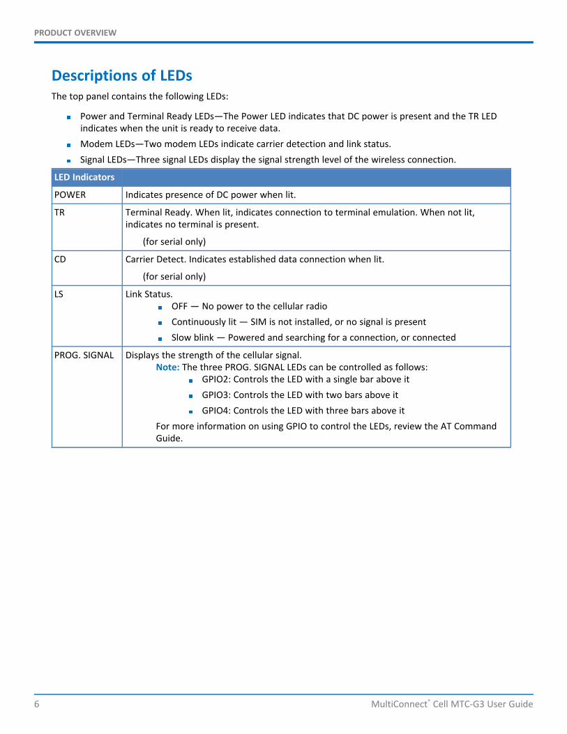
Descriptions of LEDsThe top panel contains the following LEDs:
Power and Terminal Ready LEDs—The Power LED indicates that DC power is present and the TR LEDindicates when the unit is ready to receive data.Modem LEDs—Two modem LEDs indicate carrier detection and link status.Signal LEDs—Three signal LEDs display the signal strength level of the wireless connection.
LED Indicators
POWER Indicates presence of DC power when lit.
TR Terminal Ready. When lit, indicates connection to terminal emulation. When not lit,indicates no terminal is present.
(for serial only)
CD Carrier Detect. Indicates established data connection when lit.
(for serial only)
LS Link Status.OFF — No power to the cellular radioContinuously lit — SIM is not installed, or no signal is presentSlow blink — Powered and searching for a connection, or connected
PROG. SIGNAL Displays the strength of the cellular signal.Note: The three PROG. SIGNAL LEDs can be controlled as follows:
GPIO2: Controls the LED with a single bar above itGPIO3: Controls the LED with two bars above itGPIO4: Controls the LED with three bars above it
For more information on using GPIO to control the LEDs, review the AT CommandGuide.
PRODUCT OVERVIEW
MultiConnect® Cell MTC-G3 User Guide 7
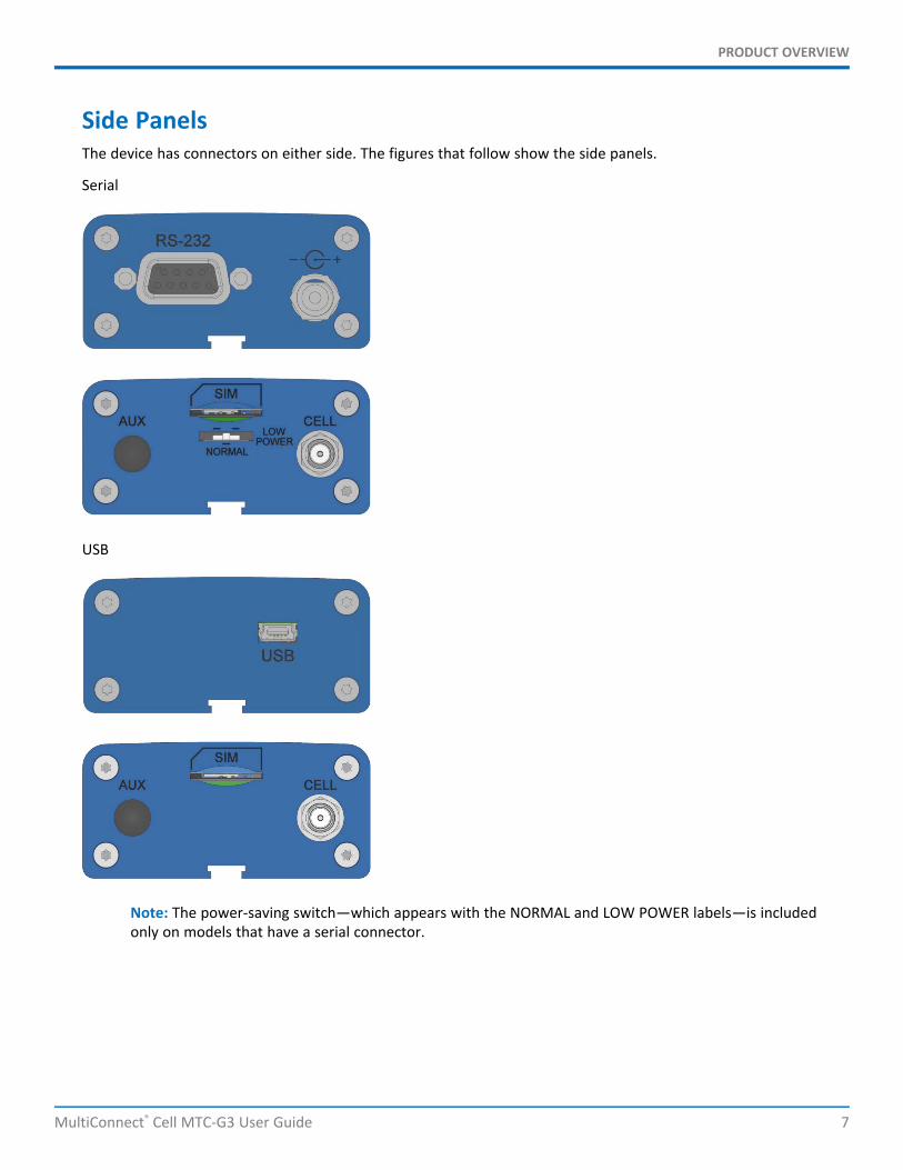
Side PanelsThe device has connectors on either side. The figures that follow show the side panels.
Serial
USB
Note: The power-saving switch—which appears with the NORMAL and LOW POWER labels—is includedonly on models that have a serial connector.

PRODUCT OVERVIEW
8 MultiConnect® Cell MTC-G3 User Guide
SpecificationsCategory Description
General
Performance GPRS Class 10
Frequency Bands Quad-band EGSM 850/900/1800/1900 MHz
Speed
Packet Data Up to 85.6 Kbps downlink and uplink
SMS
SMS Point-to-Point Messaging
Mobile-Terminated SMS
Mobile-Originated SMS
Connectors
Cellular Female SMA
RS-232 DE9
USB Mini-B, USB 2.0 high speed or better
Power 2.5 mm miniature screw-on, RS-232 models
Power Requirements
Voltage1 Serial: 5 V to 32 V DC
USB 5 V
Physical Description
Dimensions Dimensions are shown in the section “Dimensions” that follows.
Weight 8.2 ounces or 230 grams
Environment
Operating Temperature2 -40° C to +85° C
Humidity Relative humidity 15% to 93% non-condensing
Certifications, Compliance, Warranty
EMC Compliance EN 55022
EN 55024
Radio Compliance EN 301 511
EN 301 489-1
EN 301 489-7
PRODUCT OVERVIEW
MultiConnect® Cell MTC-G3 User Guide 9
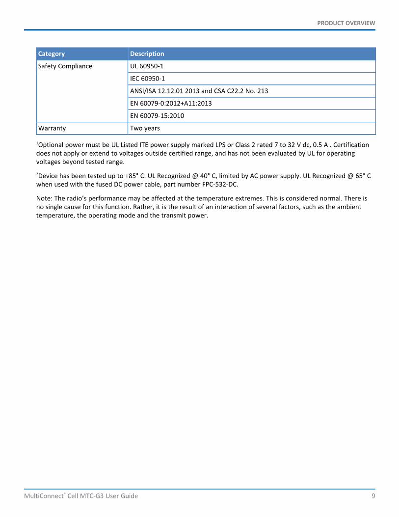
Category Description
Safety Compliance UL 60950-1
IEC 60950-1
ANSI/ISA 12.12.01 2013 and CSA C22.2 No. 213
EN 60079-0:2012+A11:2013
EN 60079-15:2010
Warranty Two years
1Optional power must be UL Listed ITE power supply marked LPS or Class 2 rated 7 to 32 V dc, 0.5 A . Certificationdoes not apply or extend to voltages outside certified range, and has not been evaluated by UL for operatingvoltages beyond tested range.2Device has been tested up to +85° C. UL Recognized @ 40° C, limited by AC power supply. UL Recognized @ 65° Cwhen used with the fused DC power cable, part number FPC-532-DC.
Note: The radio’s performance may be affected at the temperature extremes. This is considered normal. There isno single cause for this function. Rather, it is the result of an interaction of several factors, such as the ambienttemperature, the operating mode and the transmit power.
PRODUCT OVERVIEW
10 MultiConnect® Cell MTC-G3 User Guide
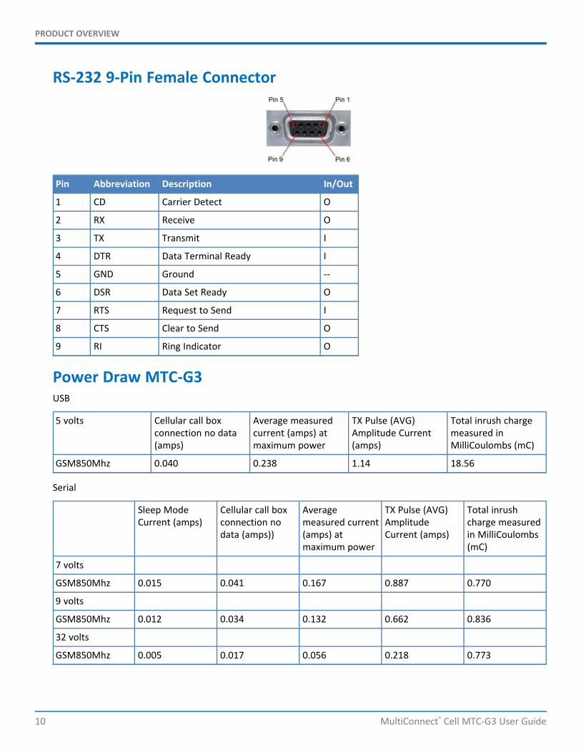
RS-232 9-Pin Female Connector
Pin Abbreviation Description In/Out
1 CD Carrier Detect O
2 RX Receive O
3 TX Transmit I
4 DTR Data Terminal Ready I
5 GND Ground --
6 DSR Data Set Ready O
7 RTS Request to Send I
8 CTS Clear to Send O
9 RI Ring Indicator O
Power Draw MTC-G3USB
5 volts Cellular call boxconnection no data(amps)
Average measuredcurrent (amps) atmaximum power
TX Pulse (AVG)Amplitude Current(amps)
Total inrush chargemeasured inMilliCoulombs (mC)
GSM850Mhz 0.040 0.238 1.14 18.56
Serial
Sleep ModeCurrent (amps)
Cellular call boxconnection nodata (amps))
Averagemeasured current(amps) atmaximum power
TX Pulse (AVG)AmplitudeCurrent (amps)
Total inrushcharge measuredin MilliCoulombs(mC)
7 volts
GSM850Mhz 0.015 0.041 0.167 0.887 0.770
9 volts
GSM850Mhz 0.012 0.034 0.132 0.662 0.836
32 volts
GSM850Mhz 0.005 0.017 0.056 0.218 0.773

PRODUCT OVERVIEW
MultiConnect® Cell MTC-G3 User Guide 11
DimensionsSerial
PRODUCT OVERVIEW
12 MultiConnect® Cell MTC-G3 User Guide
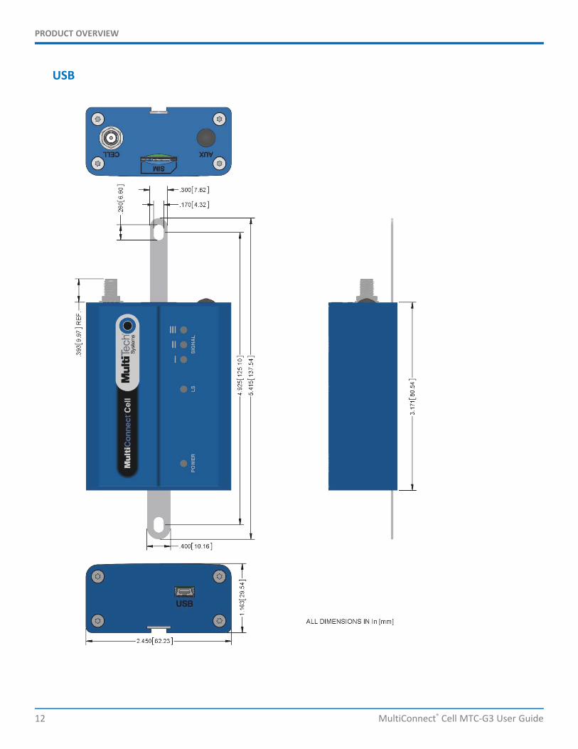
USB
PRODUCT OVERVIEW
MultiConnect® Cell MTC-G3 User Guide 13
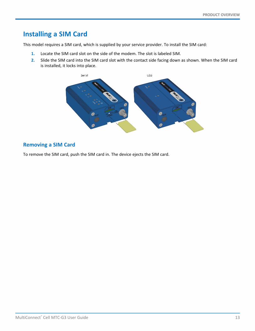
Installing a SIM CardThis model requires a SIM card, which is supplied by your service provider. To install the SIM card:
1. Locate the SIM card slot on the side of the modem. The slot is labeled SIM.2. Slide the SIM card into the SIM card slot with the contact side facing down as shown. When the SIM card
is installed, it locks into place.
Removing a SIM Card
To remove the SIM card, push the SIM card in. The device ejects the SIM card.
SAFETY WARNINGS
14 MultiConnect® Cell MTC-G3 User Guide
Chapter 2 – Safety WarningsRadio Frequency (RF) SafetyDue to the possibility of radio frequency (RF) interference, it is important that you follow any special regulationsregarding the use of radio equipment. Follow the safety advice given below.
Operating your device close to other electronic equipment may cause interference if the equipment isinadequately protected. Observe any warning signs and manufacturers’ recommendations.Different industries and businesses restrict the use of cellular devices. Respect restrictions on the use ofradio equipment in fuel depots, chemical plants, or where blasting operations are in process. Followrestrictions for any environment where you operate the device.Do not place the antenna outdoors.Switch OFF your wireless device when in an aircraft. Using portable electronic devices in an aircraft mayendanger aircraft operation, disrupt the cellular network, and is illegal. Failing to observe this restrictionmay lead to suspension or denial of cellular services to the offender, legal action, or both.Switch OFF your wireless device when around gasoline or diesel-fuel pumps and before filling your vehiclewith fuel.Switch OFF your wireless device in hospitals and any other place where medical equipment may be in use.
Interference with Pacemakers and Other Medical DevicesPotential interferenceRadio frequency energy (RF) from cellular devices can interact with some electronic devices. This iselectromagnetic interference (EMI). The FDA helped develop a detailed test method to measure EMI of implantedcardiac pacemakers and defibrillators from cellular devices. This test method is part of the Association for theAdvancement of Medical Instrumentation (AAMI) standard. This standard allows manufacturers to ensure thatcardiac pacemakers and defibrillators are safe from cellular device EMI.
The FDA continues to monitor cellular devices for interactions with other medical devices. If harmful interferenceoccurs, the FDA will assess the interference and work to resolve the problem.
Precautions for pacemaker wearersIf EMI occurs, it could affect a pacemaker in one of three ways:
Stop the pacemaker from delivering the stimulating pulses that regulate the heart's rhythm.Cause the pacemaker to deliver the pulses irregularly.Cause the pacemaker to ignore the heart's own rhythm and deliver pulses at a fixed rate.
Based on current research, cellular devices do not pose a significant health problem for most pacemaker wearers.However, people with pacemakers may want to take simple precautions to be sure that their device doesn't causea problem.
Keep the device on the opposite side of the body from the pacemaker to add extra distance between thepacemaker and the device.Avoid placing a turned-on device next to the pacemaker (for example, don’t carry the device in a shirt orjacket pocket directly over the pacemaker).

SAFETY WARNINGS
MultiConnect® Cell MTC-G3 User Guide 15
Hazardous Locations WarningsClass I, Division 2, Groups A, B, C, and D Hazardous Locations (US and Canada)ANSI_ISA_12.12.01_2013 and CSA C22.2 No. 213
-HZ models only
1. The MTC modem is a OPEN-TYPE device and is intended for installation into a IP54 style enclosure. Theenclosure would only allow access to the modem via a key or tool.
2. THIS EQUIPMENT IS SUITABLE FOR USE IN CLASS I, DIVISION 2, GROUPS A, B, C, AND D OR NON-HAZARDOUS LOCATIONS ONLY.
3. WARNING – Explosion Hazard – Substituting components may impair suitability for Class I Division 2.4. WARNING – Explosion Hazard – Do not disconnect equipment unless power has been switched off or the
area is known to be non-hazardous.5. WARNING – Explosion Hazard - Do not replace the fuse or battery unless power has been switched off or
the area is known to be non-hazardous.6. WARNING – Do not install or remove SIM card unless power has been switched off or the area is known
to be non-hazardous.
Avertissements relatifs à l'installation et aux emplacements dangereux
1. Le modem MTC est un produit "open-type" et il est prévu pour etre installé dans des boitiers de typeIP54.Ce type de boitier fournira uniquement un accès au modem grâce à une clé ou un outils spécifique.
2. CET ÉQUIPEMENT EST ADAPTÉ EXCLUSIVEMENT POUR UNE UTILISATION EN ZONE DE CLASSE I, DIVISION2, GROUPES A, B, C, ET D OU EN ZONE NON DANGEREUSE.
3. AVERTISSEMENT – Risque d'explosion – Le remplacement des composants peut annuler la compatibilitédu produit avec les zones de Classe I Division 2.
4. AVERTISSEMENT – Risque d'explosion – Ne débranchez pas l'équipement sauf s'il est hors tension ou si lazone est considérée comme non dangereuse.
5. AVERTISSEMENT - Risque d'explosion - Ne remplacer le fusible ou la batterie que si l'alimentationélectrique est coupée ou que la zone est connue pour être non dangereuse.
6. AVERTISSEMENT – N'installez ou ne retirez pas de carte SIM sauf si l'alimentation a été coupée ou si lazone est considérée comme non dangereuse.
ATEX (Europe only)EN 60079-0:2012+A11:2013 & EN60079-15:2010
-HZ models only.
Hazardous Location Special ConsiderationsSpecial conditions for safe use:
MTR Series Router wireless MTC cell modem is intended for installation into an ATEX certified IP54enclosure and accessible only by the use of a tool.The equipment shall only be used in an area of not more than pollution degree 2, as defined in IEC 60664-1.Provisions shall be made to prevent the rated voltage from being exceeded by transient disturbances ofmore than 140%.

SAFETY WARNINGS
16 MultiConnect® Cell MTC-G3 User Guide
The device is intended to be powered by a Certified SELV non-energy hazardous power supply.
AntennaThe antenna intended for use with this unit meets the requirements for mobile operating configurations and forfixed mounted operations, as defined in 2.1091 and 1.1307 of the FCC rules for satisfying RF exposure compliance.If an alternate antenna is used, consult user documentation for required antenna specifications.
INSTALLING AND USING THE DEVICE
MultiConnect® Cell MTC-G3 User Guide 17
Chapter 3 – Installing and Using the DeviceInstalling the Device
1. Connect a suitable antenna to the antenna connector.2. If you are using the serial version of this device:
Connect the DE9 male connector (9-pin) of the RS-232 cable to the RS-232 connector on the device, thenconnect the other end to the serial port on the other desired device.Screw-on the power lead from the power supply module into the power connection on the device.Plug the power supply into your power source.
3. If you are using the USB version of this device:For information about the USB cable that helps power your device, see the section "USB CableRecommendations."The USB cable uses power from the USB power line. Connect one end of the USB cable to your computeror other USB high power device, such as a hub.Connect the other end to the device's USB connector.
4. The POWER LED lights after the device powers up.
Placing Serial Devices in Power Save ModeYou can place devices that have a serial connector in low power mode. When the device is in low powermode—which is also sometimes called sleep mode or power save mode—the device's radio is operating with littlepower. A power save switch on the device determines if the device's radio can operate in normal or low powermode.
You might want your device to go into low power mode if batteries are used to power the device. For example,you might want to use your device outdoors, and have it powered by a solar charged battery. By using low power,you can save time and money by not having to replace batteries on devices operating in the field.
You can use many techniques to place the device into low power (sleep) mode. This example uses data terminalready (DTR) and the AT command +CFUN=5. For other techniques, review the AT command guide for your device,as described in the Documentation topic in this guide.
You can make the device "wake up" from sleep mode by using the wake-on-ring feature: In the example thatfollows, the ring indicator line wakes the host processor when the radio receives an incoming call or SMS message.Your application then needs to act on the ring indication and wake up the device by asserting DTR.
Using Low Power ModeTo set up the device so it can be placed into low power mode:
1. Set the power-save switch to LOW.2. On the RS-232 interface, ensure your application controls DTR and makes it active (on). To configure the
device for DTR control, issue either AT&D1 or AT&D2 for DTR control. The &D0 command does not allowlow power to operate.
3. To configure the device to enter low power (sleep) mode, issue AT+CFUN=5 to the radio.4. To configure the device to wake from low power mode by using the wake-on-ring feature, issue
AT#E2SMSRI=1000. This configures the ring indicator to go active for 1000 ms when an SMS message isreceived.

INSTALLING AND USING THE DEVICE
18 MultiConnect® Cell MTC-G3 User Guide
5. To have the device enter sleep mode, set DTR to inactive (off) on the RS-232 interface. The clear to send(CTS) signal is off when the device is in sleep mode.
USB Cable RecommendationsIf your device has a USB connector, to avoid enumeration or power issues:
Use a high-speed USB cable that is as short as possible.Use a well-shielded cable with at least 24 AWG wire pair for power/ground and 28 AWG wire pair for datalines.If possible, use a USB port that connects directly to the motherboard rather than a USB port with addedcabling inside the computer chassis.Use USB 3.0 ports if available. These ports are typically rated for more current.You can order the USB cable through MultiTech. The part number is CA-USB-A-MINI-B-3
Powering Down Your DeviceCAUTION: Failing to properly power down the device before removing power may corrupt your device's filesystem.
To properly power down your device, use the following sequence :
1. Issue the AT#SHDN command.2. Wait 30 seconds.3. Power off or disconnect power.
Mounting Device to Flat Surface1. Locate the groove on the bottom of the device.2. Slide the mounting rod through the groove.3. To secure the rod to the desired surface, place and tighten two screws in the holes on either end of the
mounting rod. The dimensions illustration in this guide shows the mounting rod, as well as thedimensions for placement of the screws.

ANTENNA AND ACTIVATION INFORMATION
MultiConnect® Cell MTC-G3 User Guide 19
Chapter 4 – Antenna and Activation InformationAntennaThe antenna intended for use with this unit meets the requirements for mobile operating configurations and forfixed mounted operations, as defined in 2.1091 and 1.1307 of the FCC rules for satisfying RF exposure compliance.If an alternate antenna is used, consult user documentation for required antenna specifications.
Antenna InformationThis device was approved with the following antenna:
Manufacturer: San Jose
Description: Penta band antenna
Model Number: EEN-502
Multi-Tech Part Number: 45009780L
Multi-Tech ordering information:
Model Quantity
ANPB2-1HRA 1
ANPB2-10HRA 10
ANPB2-50HRA 50
Antenna Requirements/SpecificationsFrequency range 824-960/1710-2170MHz
Impedance 50 ohm
VSWR <2.5:1
Radiation Omni directional
Polarization Linear horizontal
Antenna System Cellular DevicesThe cellular/wireless performance depends on the implementation and antenna design. The integration of theantenna system into the product is a critical part of the design process; therefore, it is essential to consider it earlyso the performance is not compromised. If changes are made to the device's certified antenna system, thenrecertification will be required by specific network carriers.
Account Activation for Cellular DevicesSome MultiTech devices are pre-configured to operate on a specific cellular network. To use the device, you mustset up a cellular data account with your service provider. Each service provider has its own process for addingdevices to their network. To find activation steps for your device:

ANTENNA AND ACTIVATION INFORMATION
20 MultiConnect® Cell MTC-G3 User Guide
1. Go to http://www.multitech.com/support.2. Select your device.3. Scroll to Activation and click Download.
Device Phone NumberEvery device has a unique phone number. Your service provider supplies a phone number when you activate youraccount, or if your device has a SIM card, the phone number may be on it. Wireless service providerimplementation may vary. Consult with your service provider to get the phone number for your device.
USING LINUX
MultiConnect® Cell MTC-G3 User Guide 21
Chapter 5 – Using LinuxShell CommandsTesting Serial PortsTo test the serial ports created by the driver, type in a shell:
Note: Sending ATE0 is required, to avoid issues in the terminal output. It prevents the sending/receivingspurious characters to/from the modem when used with the Linux commands “echo” and “cat”
Create a PPP ConnectionMost recent Linux distributions have GUI tools for creating PPP connections; the following instructions are forcreating a PPP connection through command line interface.
PPP support must be compiled into the kernel; pppd and chat programs are also required.
H5 ExampleStep 1. Use a text editor to create a peer file containing the lines in the example below. (/dev/ttyACM0 may needto be something like /dev/ttyS0 for a serial build). Save the file as /etc/ppp/peers/H5-peer.
Example peer file:
/dev/ttyACM0connect "/usr/sbin/chat -v -f /etc/chatscripts/H5-chat"noipdefaultusepeerdnsdefaultroutenoauth
Step 2. Use a text editor to create a chat script containing the lines in the example below. In this example [APN]should be replaced with the APN assigned by your cellular provider. Save the file as /etc/chatscripts/H5-chat.
Example chat script:
ABORT "ERROR"ABORT "NO CARRIER"ABORT "BUSY""" at+cgdcont=1,"IP","[APN]"OK atd*99***1#CONNECT ""
Step 3. Use the following command line to start pppd:
pppd debug call H5-peer
This command line enables logging of debug information and tells pppd to use the peer file referenced by the calloption. After 20-30 seconds, type ifconfig and check whether a ppp interface is listed. If it is not, then check syslogfor pppd and chat events. Normally pppd/chat logging is written to /var/log/syslog (could vary depending on syslogconfiguration).

USING LINUX
22 MultiConnect® Cell MTC-G3 User Guide
EV3 ExampleStep 1. Use a text editor to create a peer file containing the lines in the example below. (/dev/ttyUSB2 may need tobe something like /dev/ttyS0 for a serial build). Save the file as /etc/ppp/peers/EV3-peer.
Example peer file:
/dev/ttyUSB2connect "/usr/sbin/chat -v -f /etc/chatscripts/EV3-chat"noipdefaultusepeerdnsdefaultroutenoauth
Step 2. Use a text editor to create a chat script containing the lines in the example below. In this example [APN]should be replaced with the APN assigned by your cellular provider. Save the file as /etc/chatscripts/EV3-chat.
Example chat script:
ABORT "ERROR"ABORT "NO CARRIER"ABORT "BUSY""" atOK atd#777CONNECT ""
Step 3. Use the following command line to start pppd:
pppd debug call EV3-peer
This command line enables logging of debug information and tells pppd to use the peer file referenced by the calloption.
After 20-30 seconds, type ifconfig and check whether a ppp interface is listed. If it is not, then check syslog forpppd and chat events. Normally pppd/chat logging is written to /var/log/syslog (could vary depending on syslogconfiguration).
CONFIGURING AND COMMUNICATING WITH YOUR DEVICE
MultiConnect® Cell MTC-G3 User Guide 23
Chapter 6 – Configuring and Communicating withYour Device
Interacting with Your Device OverviewThis section describes how to use AT commands to interact with your device. Using terminal software such asKermit, you can issue AT commands to communicate with and configure your modem. The AT commands let youestablish, read and modify device parameters and help you control how the device operates. This sectiondocuments basic interactions with your device, such as verifying signal strength and network registrations, sendingand reading SMS text messages, and sending and receiving data.
Generally, USB modems are used as unintelligent bit pipes. In Windows, this means you create a dial-up networkconnection that uses the Windows IP stack to use the modem to create a PPP connection to the cellular network.The modem is assigned an IP address from the cellular carrier. This connection provides Internet access and is thebasis for TCP/IP communication for sending and receiving email, creating TCP/UDP Sockets, or putting and gettingfiles from an FTP server.
In Linux, PPPD is used to dial the modem and create the connection to the cellular TCP/IP network. This providesInternet access for sending and receiving email, creating TCP/UDP Sockets, or putting and getting files from an FTPserver.
Before You BeginBefore you begin:
If you have not done so, install any drivers. Refer to the separate driver installation guide for your device.Power up your device and ensure it is connected to the computer that you use to issue AT commands.Install terminal software that can communicate with the device, such as HyperTerminal, Tera Term, Kermit,or Putty.
Using Command Mode and Online Data ModeModems have two operation modes, command and online data. When you power up the modem it is in commandmode and ready to accept AT commands.
Use AT commands to communicate with and configure your modem. They allow you to establish, read, and modifydevice parameters and control how the modem works. The device can also generate responses to AT commandsthat help determine the modem’s current state.
If the modem is in online data mode, it only accepts the Escape command (+++).
To send the modem AT Commands from terminal emulation software, set the software to match the modem’sdefault data format, which is:
Speed: 115,200 bpsData bits: 8Parity: noneStop bit: 1Flow control: hardware

CONFIGURING AND COMMUNICATING WITH YOUR DEVICE
24 MultiConnect® Cell MTC-G3 User Guide
To confirm you are communicating with the device:
Type AT and press Enter.
If the device responds with OK, you are communicating with the device.
Verifying Signal StrengthTo verify the device signal strength, enter:
AT+CSQ
The command indicates signal quality, in the form:
+CSQ: <rssi>,<ber>
Where:
<rssi> Received signal strength indication.
0 (-113) dBm or less
1 (-111) dBm
2-30 (-109) dBm - (-53) dBm / 2 dBm per step
31 (-51) dBm or greater
99 Not known or not detectable
<ber> Bit error rate, in percent
0 Less than 0.2%
1 0.2% to 0.4%
2 0.4% to 0.8%
3 0.8% to 1.6%
4 1.6% to 3.2%
5 3.2% to 6.4%
6 6.4% to 12.8%
7 More than 12.8%
99 Not known or not detectable
Note: Signal strength of 10 or higher is needed for successful packet data sessions.
ExampleA example response to AT+CSQ:

CONFIGURING AND COMMUNICATING WITH YOUR DEVICE
MultiConnect® Cell MTC-G3 User Guide 25
+CSQ: 15,1
Checking Network RegistrationBefore establishing a packet data connection, verify the is device registered on the network. To do this enter thenetwork registration report read command:
AT+CREG?
If the device returns:
+CREG: 0,1
or
+CREG: 0,5
The device is registered.
If the device returns:
+CREG: 0,2
The device is in a network searching state.
Sending and Receiving DataConnecting Device to TCP Server as TCP Client
To send data through a connect socket:
1. Define PDP Content (APN for SIM)EnterAT+CGDCONT=1,"IP","XXX.APN.com"where XXX.APN.com is the APN your cellular provider assigned to your SIM card.The device responds with OK
2. Bring up Data Connection Using Internal IP stackEnter:AT#SGACT=1,1The device responds with the IP Address the cellular provider assigned to the device on connection,followed by OK. For example:#SGACT: 25.194.185.116OK
Closing the Socket and the ConnectionTo close the socket:
Enter the escape sequence:+++
To close Socket 1, enter:AT#SH=1
CONFIGURING AND COMMUNICATING WITH YOUR DEVICE
26 MultiConnect® Cell MTC-G3 User Guide
The device responds with OK.
To close the data connection:
Enter:AT#SGACT=1,0
The device responds with OK.
Configuring Device as UDP Listener to Accept UDP Client Connections
To configure the device as a UDP client:
1. Check signal strength.Enter:AT+CSQ
2. If using a SIM card, configure the APN.Enter:AT+CGDCONT=1,"IP","XXX.APN.com"where XXX.APN.com is the APN your cellular provider assigned to your SIM card.
3. Verify device is registered on the cellular network.Enter:AT+CREG?Should return:
4. Configure socket parametersEnter:AT#SCFG=1,1,300,240,600,50
5. Activate context oneEnter:AT#SGACT=1,1
6. Set firewall rule to accept connections:AT#FRWL=1,"###.##.###.#","###.##.###.#"where ###.##.###.# represents the IP range. For example:AT#FRWL=1,"204.26.122.1","204.26.122.255"
7. Set connection ID 1 for UDP listening mode on port 7000.Enter:AT#SLUDP=1,1,7000The device responds with and unsolicited indication that a host is trying to connect to connection ID 1 onport 7000.SRING: 1
8. Accept incoming connection ID 1Enter:AT#SA=1The device indicates a client successfully established a listener connection.CONNECTYou can send and receive data.

CONFIGURING AND COMMUNICATING WITH YOUR DEVICE
MultiConnect® Cell MTC-G3 User Guide 27
Exit Data Mode and Close ConnectionTo exit data mode and close the socket:
Enter the escape sequence:+++
To close Socket 1, enter:AT#SH=1
The device responds with OK.
To close the data connection, enter:AT#SGACT=1,0
The device responds with OK.
Configuring Device as UDP Client to Connect to UDP ServerConfigure and Connect the DeviceTo configure the device as a UDP client:
1. Check signal strength.Enter:AT+CSQ
2. If using a SIM card, configure the APN.Enter:AT+CGDCONT=1,"IP","XXX.APN.com"where XXX.APN.com is the APN your cellular provider assigned to your SIM card.
3. Verify device is registered on the cellular network.Enter:AT+CREG?Should return:
4. Configure socket parametersEnter:AT#SCFG=1,1,300,240,600,50
5. Activate context oneEnter:AT#SGACT=1,1
6. Create UDP connection to Server portEnter:AT#SD=1,1,####,"###.##.###.##"where #### is the server port and ###.##.###.## is the IP number.
The device responds with OK, which indicates a successful connection. You can send and receive data through thesocket connection.
Exit Data Mode and Close ConnectionTo exit data mode and close the socket:
CONFIGURING AND COMMUNICATING WITH YOUR DEVICE
28 MultiConnect® Cell MTC-G3 User Guide
Enter the escape sequence:+++
To close Socket 1, enter:AT#SH=1
The device responds with OK.
To close the data connection, enter:AT#SGACT=1,0
The device responds with OK.
Configuring Device as UDP Listener to Accept UDP Client Connections
To configure the device as a UDP client:
1. Check signal strength.Enter:AT+CSQ
2. If using a SIM card, configure the APN.Enter:AT+CGDCONT=1,"IP","XXX.APN.com"where XXX.APN.com is the APN your cellular provider assigned to your SIM card.
3. Verify device is registered on the cellular network.Enter:AT+CREG?Should return:
4. Configure socket parametersEnter:AT#SCFG=1,1,300,240,600,50
5. Activate context oneEnter:AT#SGACT=1,1
6. Set firewall rule to accept connections:AT#FRWL=1,"###.##.###.#","###.##.###.#"where ###.##.###.# represents the IP range. For example:AT#FRWL=1,"204.26.122.1","204.26.122.255"
7. Set connection ID 1 for UDP listening mode on port 7000.Enter:AT#SLUDP=1,1,7000The device responds with and unsolicited indication that a host is trying to connect to connection ID 1 onport 7000.SRING: 1
8. Accept incoming connection ID 1Enter:AT#SA=1
CONFIGURING AND COMMUNICATING WITH YOUR DEVICE
MultiConnect® Cell MTC-G3 User Guide 29
The device indicates a client successfully established a listener connection.CONNECTYou can send and receive data.
Exit Data Mode and Close ConnectionTo exit data mode and close the socket:
Enter the escape sequence:+++
To close Socket 1, enter:AT#SH=1
The device responds with OK.
To close the data connection, enter:AT#SGACT=1,0
The device responds with OK.
Transferring FTP File to FTP Server
To connect to FTP server and upload files:
1. Check signal strength.Enter:AT+CSQ
2. If using a SIM card, configure the APN.Enter:AT+CGDCONT=1,IP,"XXX.APN.com"where XXX.APN.com is the APN your cellular provider assigned to your SIM card.
3. Verify device is registered on the cellular network.Enter:AT+CREG?Should return:
4. Activate context oneEnter:AT#SGACT=1,1
5. Set FTP operations timeout to 10 secondsEnter:AT#FTPTO=1000
6. Configure FTP server IP address with username and password.Enter:AT#FTPOPEN="###.##.###.#","username","password",0where ###.##.###.# is the IP address and the username and password for the FTP server.
7. Configure file transfer type.Enter:AT#FTPTYPE=#
CONFIGURING AND COMMUNICATING WITH YOUR DEVICE
30 MultiConnect® Cell MTC-G3 User Guide
where # is 0 for binary or 1 for ASCII.8. Enter the file name to be sent to the FTP server and initiate connection.
Enter:AT#FTPPUT="file.txt"The device responds with:CONNECT
9. Send the file through the device.
Closing the FTP Data ConnectionWhen you finish sending the file:
1. Enter the escape sequence.Enter:+++The device responds with:NO CARRIER
2. Close the FTP connection.Enter:AT#FTPCLOSE
3. Close the PPP data connection.Enter:AT#SGACT=1,0The device responds with OK.
Downloading File from FTP Server
To connect to an FTP server and download files:
1. Check signal strength.Enter:AT+CSQ
2. If using a SIM card, configure the APN.Enter:AT+CGDCONT=1,IP,"XXX.APN.com"where XXX.APN.com is the APN your cellular provider assigned to your SIM card.
3. Verify device is registered on the cellular network.Enter:AT+CREG?Should return:
4. Activate context oneEnter:AT#SGACT=1,1
5. Set FTP operations timeout to 10 secondsEnter:

CONFIGURING AND COMMUNICATING WITH YOUR DEVICE
MultiConnect® Cell MTC-G3 User Guide 31
AT#FTPTO=10006. Configure FTP server IP address with username and password.
Enter:AT#FTPOPEN="###.##.###.#","username","password",0where ###.##.###.# is the IP address and the username and password for the FTP server.
7. Configure file transfer type.Enter:AT#FTPTYPE=#where # is 0 for binary or 1 for ASCII.
8. If required, change the working directory to "folder1".Enter:AT#FTPCWD="folder1"
9. Enter the file name.Enter:AT#FTPGET="filename.txt"where filename.txt is the file you want to download.The device responds with:CONNECTThe file is received through the device. The device responds with:NO CARRIERThe data connection closes automatically when the file sending ends.
Closing the FTP Data ConnectionWhen you finish sending the file:
1. Close the FTP connection.Enter:AT#FTPCLOSE
2. Close the PPP data connection.Enter:AT#SGACT=1,0The device responds with OK.
Reading, Writing and Deleting MessagesReading Text Messages
To read a text message in text mode:
1. Put the device in text mode.Enter:AT+CMGF=1
2. Read message.Enter:AT+CMGR=1

CONFIGURING AND COMMUNICATING WITH YOUR DEVICE
32 MultiConnect® Cell MTC-G3 User Guide
Example response:
+CMGR: "REC UNREAD","+10001112222z`z","","13/09/05,13:39:40-20"How are you?OK
Where 0001112222 is the phone number.
Writing Text MessagesTo send a text message in text mode:
1. Put the device in text mode.Enter:AT+CMGF=1The device responds.OK
2. Enter the recipient's number and your message.Enter:AT+CMGS="##########">Your message here
where ########## is the recipient's number.3. Send the message.
Enter CTRL+Z.The device responds:+CMGS: #OKwhere # is the reference number of the sent message.
For example:
AT+CMGF=1OKAT+CMGS="0001112222"> How are you? <CTRL+Z to send>+CMGS: 255OK
Where 0001112222 is the phone number.
Deleting Messages
To delete one text message, enter:
AT+CMGD=I,#
where I is the index in the select storage and # is the delflag option. Enter:
0 Deletes message in the specified index.
1 Deletes all read messages. Leaves unread messages and stored device-originated messages.
CONFIGURING AND COMMUNICATING WITH YOUR DEVICE
MultiConnect® Cell MTC-G3 User Guide 33
2 Deletes all read and sent device-originated messages. Leaves unread messagesand unsent device-originated messages.
3 Deletes all read messages and sent and unsent device-orginated messages.Leaves unread messages.
4 Deletes all messages.
For example:
AT+CMGD=1 (delete message at index 1)AT+CMGD=2 (delete message at index 2 )AT+CMGD=1,0AT+CMGD=1,1AT+CMGD=1,2AT+CMGD=1,3AT+CMGD=1,4

REGULATORY INFORMATION
34 MultiConnect® Cell MTC-G3 User Guide
Chapter 7 – Regulatory InformationEMC, Safety, and R&TTE Directive Compliance
The CE mark is affixed to this product to confirm compliance with the following European Community Directives:
Council Directive 2014/30/EU on the approximation of the laws of Member States relating toelectromagnetic compatibility;andCouncil Directive 2014/35/EU on the harmonization of the laws of Member States relating to electricalequipment designed for use within certain voltage limits;andCouncil Directive 2011/65/EU on the restriction of the use of certain hazardous substances in electricaland electronic equipment;andCouncil Directive 1999/5/EC on radio equipment and telecommunications terminal equipment and themutual recognition of their conformity.
Restriction of the Use of Hazardous Substances (RoHS)
Multi-Tech Systems, Inc.
Certificate of Compliance
2011/65/EU
Multi-Tech Systems, Inc. confirms that its embedded products comply with the chemical concentration limitationsset forth in the directive 2011/65/EU of the European Parliament (Restriction of the use of certain HazardousSubstances in electrical and electronic equipment - RoHS).
These MultiTech products do not contain the following banned chemicals1:
Lead, [Pb] < 1000 PPMMercury, [Hg] < 1000 PPMHexavalent Chromium, [Cr+6] < 1000 PPMCadmium, [Cd] < 100 PPMPolybrominated Biphenyl, [PBB] < 1000 PPMPolybrominated Diphenyl Ether, [PBDE] < 1000 PPM
Environmental considerations:
Moisture Sensitivity Level (MSL) =1Maximum Soldering temperature = 260C (in SMT reflow oven)

REGULATORY INFORMATION
MultiConnect® Cell MTC-G3 User Guide 35
1Lead usage in some components is exempted by the following RoHS annex, therefore higher lead concentrationwould be found in some modules (>1000 PPM);
- Resistors containing lead in a glass or ceramic matrix compound.
REACH StatementRegistration of SubstancesAfter careful review of the legislation and specifically the definition of an “article” as defined in EC Regulation1907/2006, Title II, Chapter 1, Article 7.1(a)(b), it is our current view that Multi-Tech Systems, Inc. products wouldbe considered as “articles.” In light of the definition in § 7.1(b) which requires registration of an article only if itcontains a regulated substance that “is intended to be released under normal or reasonably foreseeable conditionsof use,” our analysis is that Multi-Tech Systems, Inc. products constitute nonregisterable articles for their intendedand anticipated use.
Substances of Very High Concern (SVHC)Per the candidate list of Substances of Very High Concern (SVHC) published October 28, 2008 we have reviewedthese substances and certify the Multi-Tech Systems, Inc. products are compliant per the EU “REACH”requirements of less than 0.1% (w/w) for each substance. If new SVHC candidates are published by the EuropeanChemicals Agency, and relevant substances have been confirmed to be greater than 0.1% (w/w), Multi-TechSystems, Inc. will provide updated compliance status.
Multi-Tech Systems, Inc. also declares it has been duly diligent in ensuring that the products supplied are compliantthrough a formalized process which includes collection and validation of materials declarations and selectivematerials analysis where appropriate. This data is controlled as part of a formal quality system and will be madeavailable upon request.
Waste Electrical and Electronic Equipment StatementWEEE DirectiveThe WEEE Directive places an obligation on EU-based manufacturers, distributors, retailers, and importers to take-back electronics products at the end of their useful life. A sister directive, ROHS (Restriction of HazardousSubstances) complements the WEEE Directive by banning the presence of specific hazardous substances in theproducts at the design phase. The WEEE Directive covers all MultiTech products imported into the EU as of August13, 2005. EU-based manufacturers, distributors, retailers and importers are obliged to finance the costs of recoveryfrom municipal collection points, reuse, and recycling of specified percentages per the WEEE requirements.
Instructions for Disposal of WEEE by Users in the European UnionThe symbol shown below is on the product or on its packaging, which indicates that this product must not bedisposed of with other waste. Instead, it is the user's responsibility to dispose of their waste equipment by handingit over to a designated collection point for the recycling of waste electrical and electronic equipment. The separatecollection and recycling of your waste equipment at the time of disposal will help to conserve natural resourcesand ensure that it is recycled in a manner that protects human health and the environment. For more informationabout where you can drop off your waste equipment for recycling, please contact your local city office, yourhousehold waste disposal service or where you purchased the product.
July, 2005

REGULATORY INFORMATION
36 MultiConnect® Cell MTC-G3 User Guide
REGULATORY INFORMATION
MultiConnect® Cell MTC-G3 User Guide 37
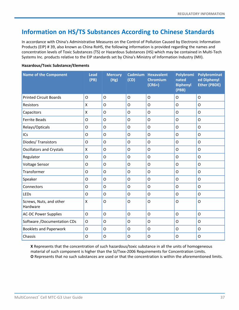
Information on HS/TS Substances According to Chinese StandardsIn accordance with China's Administrative Measures on the Control of Pollution Caused by Electronic InformationProducts (EIP) # 39, also known as China RoHS, the following information is provided regarding the names andconcentration levels of Toxic Substances (TS) or Hazardous Substances (HS) which may be contained in Multi-TechSystems Inc. products relative to the EIP standards set by China's Ministry of Information Industry (MII).
Hazardous/Toxic Substance/Elements
Name of the Component Lead(PB)
Mercury(Hg)
Cadmium(CD)
HexavalentChromium(CR6+)
PolybrominatedBiphenyl(PBB)
Polybrominated DiphenylEther (PBDE)
Printed Circuit Boards O O O O O O
Resistors X O O O O O
Capacitors X O O O O O
Ferrite Beads O O O O O O
Relays/Opticals O O O O O O
ICs O O O O O O
Diodes/ Transistors O O O O O O
Oscillators and Crystals X O O O O O
Regulator O O O O O O
Voltage Sensor O O O O O O
Transformer O O O O O O
Speaker O O O O O O
Connectors O O O O O O
LEDs O O O O O O
Screws, Nuts, and otherHardware
X O O O O O
AC-DC Power Supplies O O O O O O
Software /Documentation CDs O O O O O O
Booklets and Paperwork O O O O O O
Chassis O O O O O O
X Represents that the concentration of such hazardous/toxic substance in all the units of homogeneousmaterial of such component is higher than the SJ/Txxx-2006 Requirements for Concentration Limits.O Represents that no such substances are used or that the concentration is within the aforementioned limits.
REGULATORY INFORMATION
38 MultiConnect® Cell MTC-G3 User Guide
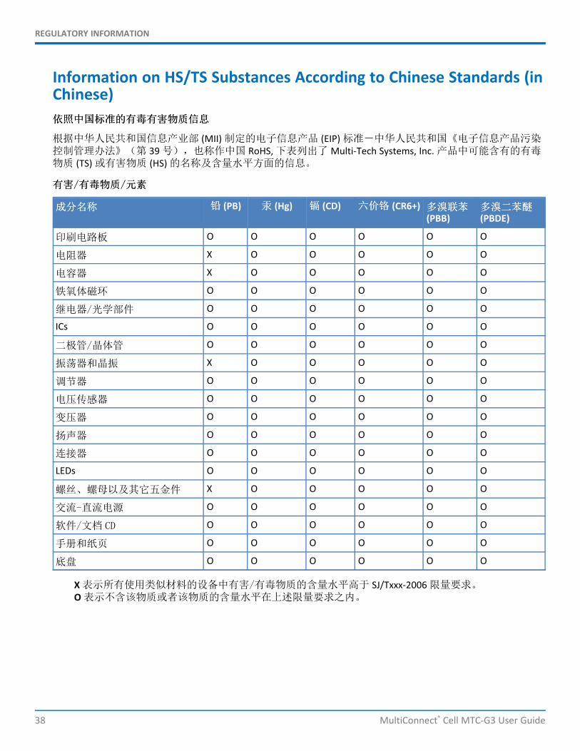
Information on HS/TS Substances According to Chinese Standards (inChinese)依依照照中中国国标标准准的的有有毒毒有有害害物物质质信信息息
根据中华人民共和国信息产业部 (MII) 制定的电子信息产品 (EIP) 标准-中华人民共和国《电子信息产品污染控制管理办法》(第 39 号),也称作中国 RoHS, 下表列出了 Multi-Tech Systems, Inc. 产品中可能含有的有毒物质 (TS) 或有害物质 (HS) 的名称及含量水平方面的信息。
有有害害//有有毒毒物物质质//元元素素
成成分分名名称称 铅铅 (PB) 汞汞 (Hg) 镉镉 (CD) 六六价价铬铬 (CR6+) 多多溴溴联联苯苯(PBB)
多多溴溴二二苯苯醚醚(PBDE)
印刷电路板 O O O O O O
电阻器 X O O O O O
电容器 X O O O O O
铁氧体磁环 O O O O O O
继电器/光学部件 O O O O O O
ICs O O O O O O
二极管/晶体管 O O O O O O
振荡器和晶振 X O O O O O
调节器 O O O O O O
电压传感器 O O O O O O
变压器 O O O O O O
扬声器 O O O O O O
连接器 O O O O O O
LEDs O O O O O O
螺丝、螺母以及其它五金件 X O O O O O
交流-直流电源 O O O O O O
软件/文档 CD O O O O O O
手册和纸页 O O O O O O
底盘 O O O O O O
X 表示所有使用类似材料的设备中有害/有毒物质的含量水平高于 SJ/Txxx-2006 限量要求。O 表示不含该物质或者该物质的含量水平在上述限量要求之内。