EVALUATION OF A PHOTOGRAMMETRIC SYSTEM … · THE CLOSED LOOP CONTROL OF ROBOTS PERFORMING DRILLING...
8
EVALUATION OF A PHOTOGRAMMETRIC SYSTEM EMPLOYED IN THE CLOSED LOOP CONTROL OF ROBOTS PERFORMING DRILLING AND FASTENING OF AERONAUTICAL STRUCTURAL ASSEMBLY Daniel Yuji Kurematsu Amorim, [email protected] Instituto Tecnológico de Aeronáutica – ITA, Praça Marechal Eduardo Gomes 50, São José dos Campos, São Paulo, Brasil Ricardo Suterio, [email protected] Instituto Tecnológico de Aeronáutica – ITA, Praça Marechal Eduardo Gomes 50, São José dos Campos, São Paulo, Brasil Instituto Nacional de Pesquisas Espaciais – INPE, Av. dos Astronautas 1758, São José dos Campos, São Paulo, Brasil Luis Gonzaga Trabasso, [email protected] Instituto Tecnológico de Aeronáutica – ITA, Praça Marechal Eduardo Gomes 50, São José dos Campos, São Paulo, Brasil Abstract. The automation of structural assemblies in the aeronautical industry needs a high level of accuracy and repeatability. Robots are employed in the entire joining process and, more specifically, in the riveting of the various fuselage sections. In order to measure the correct positioning of the robots during the riveting process, a large volume metrology system is needed. This paper evaluates a photogrammetry system with an accuracy level greater than a hundred micrometers. It presents an experiment which verifies this accuracy by comparing its results to the readings of a coordinate measuring machine. Then, a repeatability test is carried out to evaluate whether the system outputs the same distance measurements between two points. It is shown that the errors increase as the measured object moves away from the sensors. However, the observed results are always within the expected range. The analysis of the experiments shows that a photogrammetric metrology system is adequate for the automation of aeronautical assemblies, both for measurements and for the positioning correction in closed loop applications. Keywords: photogrammetry system, metrology, fuselage assembly. 1. INTRODUCTION The increasing employment of robots in industrial manufacture is evident in the international scenario. In order to reduce problems generated by systematic human error, increase speed and reduce production costs, it is essential to implement automation solutions in manufacturing processes (Kleebaur, 2005). The use of robots in the riveting process of the various sections of the fuselage is essential to increase production rates. An industrial robot such as the Kuka TM KR210, shown in Fig. 1, could be employed for this function as DeVlieg et al (2002) do with the Kuka 350. However, its repeatability is 0.12 mm, according to Kuka (2009), thus not accurate enough for such application. Figure 1. Kuka TM KR210 Robot To ensure proper positioning of the tool, it is necessary to use a coordinate measuring equipment for large volumes. Figure 2 presents the K-Series from Nikon, a photogrammetry equipment which, according to its manufacturer, suits the needs of aircraft assembly. The equipment works with a 17m³ working volume. Metris (2009) says that the ABCM Symposium Series in Mechatronics - Vol. 5 Copyright © 2012 by ABCM Section VIII - Sensors & Actuators Page 1307
Transcript of EVALUATION OF A PHOTOGRAMMETRIC SYSTEM … · THE CLOSED LOOP CONTROL OF ROBOTS PERFORMING DRILLING...

EVALUATION OF A PHOTOGRAMMETRIC SYSTEM EMPLOYED IN
THE CLOSED LOOP CONTROL OF ROBOTS PERFORMING DRILLING
AND FASTENING OF AERONAUTICAL STRUCTURAL ASSEMBLY
Daniel Yuji Kurematsu Amorim, [email protected] Instituto Tecnológico de Aeronáutica – ITA, Praça Marechal Eduardo Gomes 50, São José dos Campos, São Paulo, Brasil
Ricardo Suterio, [email protected] Instituto Tecnológico de Aeronáutica – ITA, Praça Marechal Eduardo Gomes 50, São José dos Campos, São Paulo, Brasil Instituto Nacional de Pesquisas Espaciais – INPE, Av. dos Astronautas 1758, São José dos Campos, São Paulo, Brasil
Luis Gonzaga Trabasso, [email protected] Instituto Tecnológico de Aeronáutica – ITA, Praça Marechal Eduardo Gomes 50, São José dos Campos, São Paulo, Brasil
Abstract. The automation of structural assemblies in the aeronautical industry needs a high level of accuracy and
repeatability. Robots are employed in the entire joining process and, more specifically, in the riveting of the various
fuselage sections. In order to measure the correct positioning of the robots during the riveting process, a large volume
metrology system is needed. This paper evaluates a photogrammetry system with an accuracy level greater than a
hundred micrometers. It presents an experiment which verifies this accuracy by comparing its results to the readings of
a coordinate measuring machine. Then, a repeatability test is carried out to evaluate whether the system outputs the
same distance measurements between two points. It is shown that the errors increase as the measured object moves
away from the sensors. However, the observed results are always within the expected range. The analysis of the experiments shows that a photogrammetric metrology system is adequate for the automation of aeronautical
assemblies, both for measurements and for the positioning correction in closed loop applications.
Keywords: photogrammetry system, metrology, fuselage assembly.
1. INTRODUCTION
The increasing employment of robots in industrial manufacture is evident in the international scenario. In order to
reduce problems generated by systematic human error, increase speed and reduce production costs, it is essential to
implement automation solutions in manufacturing processes (Kleebaur, 2005).
The use of robots in the riveting process of the various sections of the fuselage is essential to increase production rates. An industrial robot such as the KukaTM KR210, shown in Fig. 1, could be employed for this function as DeVlieg
et al (2002) do with the Kuka 350. However, its repeatability is 0.12 mm, according to Kuka (2009), thus not accurate
enough for such application.
Figure 1. KukaTM KR210 Robot
To ensure proper positioning of the tool, it is necessary to use a coordinate measuring equipment for large volumes.
Figure 2 presents the K-Series from Nikon, a photogrammetry equipment which, according to its manufacturer, suits
the needs of aircraft assembly. The equipment works with a 17m³ working volume. Metris (2009) says that the
ABCM Symposium Series in Mechatronics - Vol. 5 Copyright © 2012 by ABCM
Section VIII - Sensors & Actuators Page 1307

minimum working distance is 1.6 meters and the maximum is 6.0 meters. The manufacturer’s datasheet specifies the
accuracy varying according to the distance from the camera to the object and is divided into three zones, as shown in
Tab. 1.
Table 1. K-Series system nominal accuracy
Distance from camera Accuracy error
Zone 1 1.5 to 3.0 meters 60μm + 10μm/m
Zone 2 3.0 to 5.0 meters 70μm + 25μm/m
Zone 3 5.0 to 6.0 meters 140μm + 25μm/m
The measurement system is equipped with three linear CCD cameras. Each camera has a specific arrangement of its
pixels’ direction. The cameras capture infrared signals, emitted by proprietary LEDs. All LEDs are connected to a
controller, and so is the camera. The controller synchronizes the LEDs with the camera, making each LED flash at a
time, in a pre-defined sequence. Thus, the K-Series system can identify each LED attached to a body, the robot in this
case, and calculate the position in space of each point individually, using a triangulation method, also shown in Fig. 2.
Figure 2. K-Series photogrammetry system
To check the accuracy of the K-Series, a series of experiments were done in conjunction with a coordinated
measuring machine (CMM) Mitutoyo CrystaC 7106 presented in Fig. 3.
The Mitutoyo machine has an accuracy of (1.9 + 3 L/1000) micrometers where L is the distance between two points
(Mitutoyo, 2009). In this paper, the experiment was carried out with a displacement of 100mm, resulting in a calibrated
accuracy of 2.2 micrometers. This value is much lower than that specified for the K-Series, meeting the needs of the
experiment described below.
Figure 3. Mitutoyo CrystaC 7106 Coordinate Measuring Machine
ABCM Symposium Series in Mechatronics - Vol. 5 Copyright © 2012 by ABCM
Section VIII - Sensors & Actuators Page 1308

2. ACCURACY AND REPEATABILITY VERIFICATION OF THE K-SERIES SYSTEM
The following experiment was carried out to determine the K-Series’ accuracy and repeatability in a temperature
and humidity controlled environment. Temperature is set to 20±2°C and humidity to 50±5%.
2.1. Setup of the experiment
The experiment consists of moving the Mitutoyo’s arm and measuring its position with the K-Series. Three K-
Series’ infrared LEDs are fixed on the CMM’s arm in order to emit signals that give the location in space for the
photogrammetry equipment, as shown in Fig. 4.
Figure 4. K-Series LEDs attached to the Mitutoyo CMM
The second step to setup the experiment is to define the K-Series’ coordinate system. For this, the Mitutoyo’s measuring arm is manually commanded to move to its origin point which is measured by the optical equipment. Then,
the machine is commanded to move only in its X-axis and the K-Series collects the new position. With the K-Series
proprietary software Geoloc, a line is created from these two sampled points, defining the X-axis’ direction and
orientation for the photogrammetry system. Similarly, the Mitutoyo machine is commanded into a Y-axis only
movement and the Nikon equipment reads the new position and defines the Y-axis for its coordinate system. The K-
Series’ Z axis is created mathematically in Geoloc, from the previous two defined axes.
2.2. Procedure of the experiment
With the K-Series coordinate system defined, the experiment itself is started by moving the machine arm in
different positions and measuring them using the optical system, as described below.
According to Fig. 5, the machine from Mitutoyo reaches thirteen specific points and the K-Series equipment measures each position. The first point (P0) is the origin of the coordinate system for both equipments. The Mitutoyo’s
arm is commanded to that point and K-Series measures it. Then, it moves 100mm on the X-axis, reaching P1=(100,0,0),
and the photogrammetry system measures this position. After that, the Mitutoyo returns to the origin (P2=P0) and K-
Series reads its position. Similarly, it reaches the points P3=(0,100,0) and P5=(0,0,100). Finally, it performs the same
motion in the opposite orientation and returns to the origin. For each of the thirteen points, the K-Series system
measures the Mitutoyo’s arm position and the results are exported to a text file to be analyzed.
ABCM Symposium Series in Mechatronics - Vol. 5 Copyright © 2012 by ABCM
Section VIII - Sensors & Actuators Page 1309

Figure 5. CMM moving points
The experiment is comprised of thirteen points (P0, P1, P2 ... P12) and is performed with two replications. The
number of samples is thus 26 points. For each of the points, the positional error is calculated according to Eq. 1, where
the MEAS and NOM indexes correspond to the measured and the nominal coordinates, respectively.
222 )()()( NOMMEASNOMMEASNOMMEAS zzyyxxR (1)
All of the points are analyzed to obtain the accuracy and precision of the K-Series system. After this analysis, the
called “origin points” sampled (P0, P2, P4 ... P12) are analyzed to assess the repeatability of the photogrammetry system at the first zone.
This experiment is based on the European Standard EN ISO 9283 (ISO, 1998), but instead of evaluating the robot
(in this case, the Mitutoyo’s arm), the present work qualifies the measuring equipment, i.e. the K-Series, considering the
arm as the reference. The points used to evaluate the equipment are not on the corners of the cube, but on its faces, as it
is proposed by Villani et al. (2010).
The Villani et al. (2010) work evaluates the Kuka KR-210 robot using the K-Series as a reference measuring
machine. The present work, however, qualifies the earlier experiments by evaluating the K-Series using the same
method but with the Mitutoyo machine as the reference.
2.2. Results of the experiment
Figure 6 shows the resulting errors from the measured points with the K-Series. Observe that the errors are accentuated in the offset points of the origin, since it adds the random error with the K-Series coordinate system’s
creation error.
Figure 6. K-Series’ measurements error
ABCM Symposium Series in Mechatronics - Vol. 5 Copyright © 2012 by ABCM
Section VIII - Sensors & Actuators Page 1310
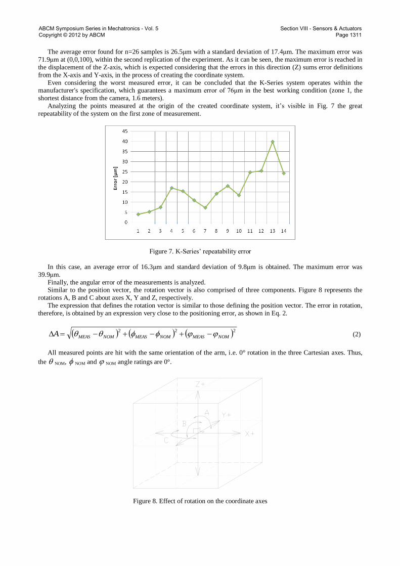
The average error found for n=26 samples is 26.5μm with a standard deviation of 17.4μm. The maximum error was
71.9μm at (0,0,100), within the second replication of the experiment. As it can be seen, the maximum error is reached in
the displacement of the Z-axis, which is expected considering that the errors in this direction (Z) sums error definitions
from the X-axis and Y-axis, in the process of creating the coordinate system.
Even considering the worst measured error, it can be concluded that the K-Series system operates within the manufacturer's specification, which guarantees a maximum error of 76μm in the best working condition (zone 1, the
shortest distance from the camera, 1.6 meters).
Analyzing the points measured at the origin of the created coordinate system, it’s visible in Fig. 7 the great
repeatability of the system on the first zone of measurement.
Figure 7. K-Series’ repeatability error
In this case, an average error of 16.3μm and standard deviation of 9.8μm is obtained. The maximum error was
39.9μm.
Finally, the angular error of the measurements is analyzed. Similar to the position vector, the rotation vector is also comprised of three components. Figure 8 represents the
rotations A, B and C about axes X, Y and Z, respectively.
The expression that defines the rotation vector is similar to those defining the position vector. The error in rotation,
therefore, is obtained by an expression very close to the positioning error, as shown in Eq. 2.
222
NOMMEASNOMMEASNOMMEASA (2)
All measured points are hit with the same orientation of the arm, i.e. 0° rotation in the three Cartesian axes. Thus,
the NOM, NOM and NOM angle ratings are 0°.
Figure 8. Effect of rotation on the coordinate axes
ABCM Symposium Series in Mechatronics - Vol. 5 Copyright © 2012 by ABCM
Section VIII - Sensors & Actuators Page 1311

Figure 9 shows the modules of the errors of orientation measured by photogrammetry equipment:
Figure 9. K-Series orientation error
The greatest error in the orientation measurements equals 0.053°, with an average of 0.014° and a standard deviation
of 0.013°. It is apparent that the accuracy of the system is suitable for measuring robot orientation as well as the tools’
orientation in the aeronautical assembly industry.
3. VERIFICATION OF REPEATABILITY VARYING K-SERIES’ MEASURING ZONES
In order to specifically check the repeatability of the K-Series in its three measuring zones, another experiment was
conducted in a larger environment, but without temperature and humidity control (as a typical application).
3.1 Setup and procedure
The experiment consists on attaching three individual and independent LEDs in a metallic body, according to Fig.
10, then measuring the separation between them. It is noteworthy that these measurements cannot be assessed in
accuracy, only repeatability, because the nominal values can’t be measured physically by another instrument for
comparison, i.e. the LEDs individual plastic housings are not accurate.
Figure 10. Body with three individual LEDs attached
ABCM Symposium Series in Mechatronics - Vol. 5 Copyright © 2012 by ABCM
Section VIII - Sensors & Actuators Page 1312

With the body placed at a distance from the camera, the measurements of each of the three LEDs are repeated ten
times with 1-second interval between each measurement, resulting in 30 point readings. Then the body is moved to a
new position and the measurements are performed similarly. The body is positioned in 16 different locations in order to
analyze the distance-from-camera influence on the measurements.
3.2. Results of the experiment
In this experiment, separation concerns about the separation distance from one LED to another, while distance
means the distance from the measured point to the photogrammetry camera. Now, it can be defined the nominal
distance (D[pos]|[pos]=1 to 16) as the mean distance of the three LEDs (z1, z2, z3) in its ten replications in relation to the
camera at one of the 16 positions, according to Eq. 3. Note that the camera’s z-axis is perpendicular to the camera and
decreases out of his front, as sawn in Fig. 3.
10/3/)(10
1
][,3][,2][,1
rep
pospospospos zzzD (3)
The separation between two LEDs (s[i,j,pos,rep]|[i,j]=[1,2];[1,3];[2,3] and rep=1 to 10) is the separation measured from
one LED (i) to a second one (j) in a specific position and replication, expressed in Eq. 4.
2
,,,,
2
,,,,
2
,,,,,,, )()()( repposjrepposirepposjrepposirepposjrepposirepposji zzyyxxs (4)
The nominal separation (S[i,j]|[i,j]=[1,2];[1,3];[2,3]) is the average separation between two LEDs (i and j) calculated
for each position and replication, according to Eq. 5.
10/16/10
1
16
1
,,,,
rep pos
repposjiji sS (5)
The error of each separation measurement (e[i,j,pos,rep]) is obtained through Eq. 6.
],[],,,[],,,[ jirepposjirepposji Sse (6)
The graph in Fig. 11 represents the separation error for each pair of LEDs, at 16 positions of the body with its 10
replications at each position (e[i,j,pos,rep]), showing that the variance of the errors increase with an increased distance from
the camera (D[pos]), but in the worst case (65um error, at 5,619mm from the camera), the result is within what is
specified by the manufacturer.
-0.08
-0.06
-0.04
-0.02
0.00
0.02
0.04
0.06
0.08
-7000 -6000 -5000 -4000 -3000 -2000 -1000 0
Distance from K-Series camera [mm]
Sepa
ratio
n er
ror [
mm
]
Figure 11. Separation error (e[i,j,pos]) vs. Distance (D[pos])
ABCM Symposium Series in Mechatronics - Vol. 5 Copyright © 2012 by ABCM
Section VIII - Sensors & Actuators Page 1313

4. CONCLUSION
The experiment conducted with the coordinate measuring machine as an auxiliary metrology system evaluates the
accuracy and repeatability of an optical measuring machine. Its analysis states that the photogrammetry equipment meets the manufacturer's specifications and can be used to measure the positioning of conventional robots in
applications requiring high accuracy and repeatability level as the aeronautical industry.
The ability to measure the orientation of a robotic arm with the K-Series photogrammetry system is also suitable for
the aeronautical industry and other applications requiring high accuracy and repeatability in orientation such as drilling
and fastening.
One of the experiments was conducted in a laboratory under controlled temperature (20±2°C) and humidity
(50±5%) to ensure the accuracy of the CMM from Mitutoyo. The photogrammetry equipment, however, has
temperature sensors and the system is capable of correcting measurement errors when the temperature ranges from
about 5°C, common in industrial environments. When there is a wider variation in temperature, the system warns that
extrapolation and requests a new referencing procedure using a proprietary standard bar and its procedures.
The main precaution to observe is when defining the K-Series coordinate system. The poor definition of the primary and secondary axes (in this work, the X-axis and Y-axis, respectively) can cause large errors, especially on the third
axis, created mathematically, thus accumulating those two errors.
A second experiment took place in a not controlled environment to broaden the working space. The results show the
high repeatability level of the photogrammetry system even at the longest visible distance from the camera, making the
K-Series suitable for the measurement in large volumes, such as aeronautical applications.
Future work will include the redefinition of the K-Series coordinate system and watching the influence in the results.
The variation of work volume must also be in focus for the next studies, as well as experiments with nominal angular
displacement. Another factor that may influence the accuracy of the K-Series system is the amount of infrared sensors
used. This study used only three sensors, but a greater number of those tends to increase the system’s accuracy.
5. ACKNOWLEDGEMENTS
The authors would like to thank Financiadora de Estudos e Projetos (FINEP) and Conselho Nacional de
Desenvolvimento Científico e Tecnológico (CNPq) for their financial support, Nikon Metrology for their product
support, and Empresa Brasileira de Aeronáutica S/A (Embraer) for the support received for this project on visits to their
premises.
6. REFERENCES
DeVlieg, R., Sitton, K., Feikert, Ed., Inmanet, J., 2002. “ONCE (ONe-sided Cell End effector) Robotic Drilling
System”. SAE International, Document Number: 2002-01-2626.
International Standardization Organization, 1998. “DIN EN ISO 9283: Manipulating industrial robots – Performance criteria and related test methods”. Geneva, 22 p.
Kleebaur, R., 2005. “Automation in Aircraft Assembly”. Planet Aerospace, n. 4.
Kuka, I. R., 2009. “KR 210-2 (Series 2000)”. Oct. 2009. <www.kuka-robotics.com>.
Metris, 2009. “K-Series Optical CMM”. Oct. 2009. <www.nikonmetrology.com>.
Mitutoyo, 2009. “Coordinate Measuring Machines Crysta-Apex C”. Oct. 2009. <www.mitutoyo.com.br>.
Villani, E., Suterio, R., Trabasso, L. G., Furtado, L. F. F., Alvarado, B. H. L. and Amorim, D. Y. K., 2010. “Metrologic
Evaluation of an Industrial Robot employed in Structural Assembly of Airplanes”. SBA Control & Automation, n. 6,
vol. 21 (in portuguese).
7. RESPONSIBILITY NOTICE
The authors are the only responsible for the printed material included in this paper.
ABCM Symposium Series in Mechatronics - Vol. 5 Copyright © 2012 by ABCM
Section VIII - Sensors & Actuators Page 1314