![[wip]LLCRousseau (pdf, 739 KiB)](https://static.fdocuments.in/doc/165x107/586dff0e1a28ab02688b5507/wipllcrousseau-pdf-739-kib.jpg)
EuroSDR_Phase2 (pdf, 438 KiB) - Infoscience - EPFL
16
EuroSDR-Project Commission 1 “Sensors, Primary Data Acquisition and Georeferencing” “Reliability of Direct Georeferencing: A Case Study on Practical Problems and Solutions” Final Report on Phase 2 Report by Klaus Legat, Jan Skaloud and Ronald Schmidt Ingenieurgemeinschaft Vermessung AVT - ZT GmbH, Austria École Polytechnique Fédérale de Lausanne (EPFL) Department of Geography, University of Zurich 1
Transcript of EuroSDR_Phase2 (pdf, 438 KiB) - Infoscience - EPFL

EuroSDR-Project
Commission 1 “Sensors, Primary Data Acquisition and Georeferencing”
“Reliability of Direct Georeferencing:
A Case Study on Practical Problems and Solutions” Final Report on Phase 2
Report by Klaus Legat, Jan Skaloud and Ronald Schmidt Ingenieurgemeinschaft Vermessung AVT - ZT GmbH, Austria
École Polytechnique Fédérale de Lausanne (EPFL) Department of Geography, University of Zurich
1

ABSTRACT .......................................................................................................................................... 3
1 INTRODUCTION ......................................................................................................................... 3
2 THEORETICAL BACKGROUND ............................................................................................. 4 2.1 Recording and processing of direct-georeferencing data ................................................. 4
2.1.1 Layout of airborne mobile-mapping systems ......................................................... 4 2.1.2 System calibration .................................................................................................. 4 2.1.3 Nominal processing steps of the GPS/INS data ..................................................... 4
2.2 Potential error sources...................................................................................................... 5
3 CASE STUDY................................................................................................................................ 6 3.1 Project characteristics....................................................................................................... 6 3.2 Provided data and information ......................................................................................... 7 3.3 Identified problems and solutions .................................................................................... 8
3.3.1 Erroneous image positions – Horizontal effects ..................................................... 8 3.3.2 Erroneous image positions – Vertical effects ....................................................... 10 3.3.3 Erroneous image-orientation angles ..................................................................... 12
3.4 Summary ........................................................................................................................ 13
4 CONCLUSIONS AND RECOMMENDATIONS..................................................................... 14
ACKNOWLEDGMENTS.................................................................................................................. 15
REFERENCES ................................................................................................................................... 15
INDEX OF FIGURES........................................................................................................................ 16
INDEX OF TABLES.......................................................................................................................... 16
2

Abstract
This report studies a practical problem related to the use of GPS/INS technology for sensor direct georeferencing. It is a case study of a specific, yet typical, situation where the performance of a GPS/INS was pronounced unsatisfactory for orientation of an airborne sensor. However, it was in fact not the poor quality of the navigation data but rather numerous disregards occurring in the flight execution and data treatment that have led to this wrong conclusion. The presented analysis reveals the errors committed at different stages of data treatment and quantifies their impact on the sensor exterior orientation. It also explains the remedies employed to mitigate their impact. The recommended procedures are drafted in a summary.
1 Introduction
The method of direct georeferencing (DG) of airborne sensors by GPS/INS is considered by many as a well-established process that increases the productivity of airborne mapping. Nevertheless, the users of this technology often encounter pitfalls related to its reliability (e.g., instrument and/or data quality) or its incorrect use (e.g., an unstable sensor mount, uncompensated effects due to platform stabilization, or inadequate datum/projection transformation procedures). While the recently published EuroSDR report investigated the former (Skaloud, 2006), this study concentrates on the practical aspects. These problems often prevent from benefiting fully from the collected GPS/INS data, or, in extreme (but not rare) cases, lead to a wrong judgment on their adequacy for a stated goal (Kremer 2006).
The core of this report is organized around a case study of a real project (Sect. 3) where such an incorrect conclusion was drawn by a company responsible for the refinement of the image orientation by an automated aero-triangulation (AAT). The first author was given the “detective task” of tracing the origins of the encountered problems. During this investigation, numerous inadequacies were identified which span the whole process from the survey setup to the transformation of the exterior orientation (EO) of the images. These findings are analyzed and their impact on the EO accuracy is quantified in comparison with correct treatment. Finally, the synthesis of the experience serves as a pretext for drafting the recommended procedures in Section 4. These recommendations should not replace but rather complete the existing manuals and suggested measures recommended by technology providers.
Apart a brief theoretical introduction provided in Sect. 2, the reader is further advised to consult the frame definitions given in Kresse et al. (2006) and the introductory material on DG by GPS/INS in Madani (2004) or Legat (2006).
3
2 Theoretical background
2.1 Recording and processing of direct-georeferencing data
2.1.1 Layout of airborne mobile-mapping systems
Apart from the image sensor(s), an airborne mobile-mapping system equipped for direct georeferencing involves one or several GPS receivers and antennas as well as an inertial measurement unit (IMU). In the most ideal case, all sensors are attached to a common rigid mounting structure, preventing variations in their relative positions and orientations. Further, the complete system requires synchronization to a common time scale, typically GPS time.
In practice, many airborne surveying companies use cameras with a retrofit IMU on a gyro-stabilized (gimbaled) platform. While this design does not affect the stability of the camera/IMU assembly, the GPS antenna is usually placed at other, remote, positions on the aircraft (Kremer 2006). In case the stabilization exerts rotations on the camera for guaranteeing an optimal image quality, the position offset (lever arm) of the GPS antenna from the IMU will change (even in the body frame of the IMU). Especially critical are designs with large along and/or lateral separations (referred to the aircraft frame); in contrast, vertical separations may be negligible due to the motion characteristics of aircraft. Such variations of the antenna offset will deteriorate the quality of the GPS/INS data, unless the gimbal angles of the camera are recorded and fed into the processing. Otherwise, the variable lever arm may be subject to poor observability in the GPS/INS integration, meaning that the estimation of the effects caused by the gimbal rotations will be critical in post-processing. Consequently, it could be difficult to correctly transfer the GPS/INS position to the image sensor.
2.1.2 System calibration
Prior to the use of the system for mapping purposes, a calibration must be performed. This concerns both the calibration of individual sensors (e.g., an aerial camera or an IMU) and the system calibration due to the aircraft mount (Kremer 2006). Thereby, the differences in orientation between the IMU and the image sensors – known as boresight orientations – must be determined. The required approaches differ among passive and active sensors (see, e.g., Skaloud and Schaer 2003, Skaloud and Lichti 2006). Furthermore, the lever arms from the IMU towards the GPS antenna(s) and image sensor(s) must be derived. The latter task is usually fulfilled by classical geodetic surveying. As the position offsets are required in the body frame of the IMU (or in the camera frame), these measurements should be performed in conditions when the axis system of the IMU is well established and known (i.e., the systematic sensor errors of the IMU have been reliably estimated or can be considered as insignificant for the stated purpose).
2.1.3 Nominal processing steps of the GPS/INS data
The processing of the GPS/INS data commences with the kinematic baseline determination between the mobile GPS equipment and one or several base stations located at precisely surveyed positions. Subsequently, the positions (and possibly also velocities) from GPS are integrated with the raw measurements of the IMU.
4
The difference in position and orientation between the IMU and the image sensor is either applied within the GPS/INS processing or in a subsequent step. Furthermore, the data need to be interpolated to the actual recording times of the image sensor. This yields the exterior orientation (EO) of the images in the earth-centered earth-fixed (ECEF) reference frame of GPS. However, as the final mapping products are usually demanded in some national coordinate frame, the EO data must be transformed accordingly (Legat 2006):
• With reference to the positions, this may require the transformation to a national geodetic datum, the application of some national map projection, and the consideration of the geoid heights. Moreover, an additional correction should be applied to minimize the distortions of the heights that arise from the curvature of the earth and the fact that an ellipsoid of revolution cannot be projected into the plane without length distortion.
• In case of the orientation angles, the transition to national coordinates may also require a datum-based transformation due to residual rotations of the national datum frame and the use of a locally best fitting ellipsoid of revolution. Further, the position-dependent convergence of meridians of the map projection must be accounted for.
Once these transformations have been applied, the EOs can be used for processing the image data. In many cases, however, an automated aero-triangulation (AAT) may be desired for controlling the quality of the direct-georeferencing results and/or improving the relative orientations of the images.
2.2 Potential error sources
Unfortunately, there are a number of potential error sources in direct georeferencing that may diminish or even ruin the quality of the EO data. Some of these error sources are (the order of items follows the sequence of the above descriptions):
• Lack of rigidity of the sensor assembly, including lever-arm variations caused by the platform stabilization.
• Synchronization errors or non-compensated sensor delays, e.g., time shifts between a camera trigger command and the actual shutter time of the camera.
• Calibration errors of sensor lever arms and boresight angles or failure to apply these parameters correctly.
• False settings or assumptions of the GPS/INS processing, e.g., concerning the modelling of systematic errors in the IMU.
• Use of wrong parameters of the national geodetic datum.
• Use of a wrong map projection, e.g., an approximate projection instead of some specific projection type that may not be supported by particular software packages.
• Failure to apply the geoid heights (if necessary) and/or the height correction required due to the length distortions arising from a map projection.
In addition to these rather technical items, another very important issue may cause severe difficulties: A lack of information exchange between different partners involved in a common mapping project
5

(especially with respect to metadata) and/or misunderstandings about the processing steps applied by the other partners.
We will encounter several of these errors in the case study described in Sect. 3.
3 Case study
To avoid offending any parties that participated in the project that serves as the basis of this case study, all references to these parties have been neutralized. Further, no details are given concerning the location of the project area.
3.1 Project characteristics
The project was performed by two partners with several years of experience in their respective fields of work. The responsibility of Company A was to perform the image flight with a frame-based camera and transform the image EOs derived by GPS/INS to national coordinates. The task of Company B was to perform an AAT with the transformed EOs supplied by Company A and a number of ground control points (GCPs) provided by the client of the project.
Some other relevant project characteristics were as follows:
• The image data were recorded in two separate flight sections with scales 1:4000 (5 lines, 174 images with IDs 1 through 174) and 1:2500 (6 lines, 401 images with IDs 180 through 585). Considering the camera focal length of approximately 30 cm, the relative flight heights above the terrain were about 1200 m and 750 m, respectively. Separate AATs had to be done for each scale.
• The results of the photogrammetric processing were requested in national coordinates of the European country in question. The definition of the national geodetic datum is general which requires a 3D similarity transformation with respect to the ECEF frame and involves a locally best fitting ellipsoid of revolution. The map projection is a non-standard variant of the Transverse Mercator (TM). Furthermore, the client requested orthometric heights.
A two-dimensional plot of the image positions of both flight sections is shown in Figure 1. The data are given in national coordinates relative to a suitable position within the project area. The flight lines were almost parallel with alternate mean azimuths of –40° (roughly north-west) and +140° (roughly south-east), respectively.
Encountered difficulties
When Company B attempted to run the AATs, it turned out that the EO data provided by Company A were not consistent with the GCPs. While the image positions could be used – notably by allowing an individual drift correction per flight line – the discrepancies of the orientation angles were out of tolerance, rendering them completely unusable.
To cope with these problems, a number of additional GCPs were measured by the client and GPS-supported ATs (mainly based on the GCPs and tie points) were performed by Company B. The first author of this report was also invited to investigate the encountered difficulties.
6
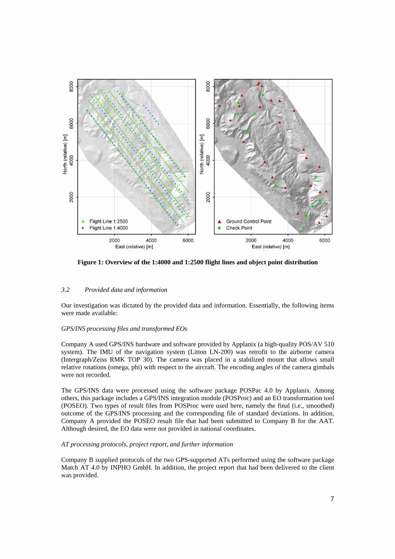
Figure 1: Overview of the 1:4000 and 1:2500 flight lines and object point distribution
3.2 Provided data and information
Our investigation was dictated by the provided data and information. Essentially, the following items were made available:
GPS/INS processing files and transformed EOs
Company A used GPS/INS hardware and software provided by Applanix (a high-quality POS/AV 510 system). The IMU of the navigation system (Litton LN-200) was retrofit to the airborne camera (Intergraph/Zeiss RMK TOP 30). The camera was placed in a stabilized mount that allows small relative rotations (omega, phi) with respect to the aircraft. The encoding angles of the camera gimbals were not recorded.
The GPS/INS data were processed using the software package POSPac 4.0 by Applanix. Among others, this package includes a GPS/INS integration module (POSProc) and an EO transformation tool (POSEO). Two types of result files from POSProc were used here, namely the final (i.e., smoothed) outcome of the GPS/INS processing and the corresponding file of standard deviations. In addition, Company A provided the POSEO result file that had been submitted to Company B for the AAT. Although desired, the EO data were not provided in national coordinates.
AT processing protocols, project report, and further information
Company B supplied protocols of the two GPS-supported ATs performed using the software package Match AT 4.0 by INPHO GmbH. In addition, the project report that had been delivered to the client was provided.
7

3.3 Identified problems and solutions
3.3.1 Erroneous image positions – Horizontal effects
In the original setup, the GPS/INS data were transformed to national coordinates using POSEO. A comparison of these results with the image positions from the ATs revealed significant discrepancies. These are shown for the 1:2500 flight lines in Figure 2 (the variable background color of the figures always indicates the different flight lines). Despite the obvious offsets in each coordinate direction, the north and east coordinates include trends that depend on the flight lines.
Figure 2: Position differences POSEO minus AT, flight section 1:2500
Considering these deviations, it is clear that the image positions from POSEO could only be used in the ATs by applying individual linear drift corrections for each flight line. As an example, the constant offsets of the 1:2500 flight lines computed by Match-AT are shown in Table 1. Clearly, the results in east and north are again correlated with the flight line. Furthermore, the values are unrealistically large: If the image positions had been transformed correctly, the constant shifts should be close to the magnitude of the GPS positioning errors (typically, some 10 cm in case of kinematic carrier-phase positioning). However, they are more than ten times greater, attesting errors in the processing.
Line Direction East offset [cm] North offset [cm] Height offset [cm] 1 NW 170.4 310.0 –124.0 2 SE 93.0 265.9 –126.8 3 NW 164.4 305.3 –128.9 4 SE 95.2 271.0 –135.3 5 NW 153.0 302.8 –133.6 6 SE 72.0 276.8 –126.4 Mean 124.7 288.6 –129.2
Table 1: GPS position bias per line as estimated by Match-AT for the 1:2500 flight
8

Three reasons were identified that have contributed to the large position disparities in Figure 2:
1. In the AT, Company B introduced the eccentricity (lever arm) of the GPS antenna with respect to the camera as [18.6, 39.7, 128.3] cm (these values had been provided by Company A). However, as the results of the GPS/INS processing had already been referred to the centre of projection of the camera by Company A, the (re-) application of the eccentricity in the AT has, in fact, falsified the positions. While the vertical component corresponds to height offset of Table 1 (the camera was stabilized in the horizon), the horizontal deviations are only partly caused by this failure.
It is worth noting that it is probably the terminology of the user interface of Match AT that has added to this serious misunderstanding between Company A and B as it instructs the user to enter the “GPS antenna eccentricity”. This is correct when performing a GPS-supported AT; when using GPS/INS, however, it is usually not the eccentricity of the GPS antenna that is relevant for the AT but the lever arm of the IMU with respect to the camera. While the latter can also be accounted for at some other stage, the GPS-INS lever arm should be introduced for a correct GPS/INS integration.
2. The dominant part of the horizontal coordinate discrepancies is due to the non-standard character of the national map projection which is not supported by POSEO and was probably only “approximated” by selecting a projection of a similar type from the available choices.
3. The residual vertical disparities were partly caused by the failure of Company A to correct the national ellipsoidal heights derived from GPS/INS by the geoid heights. Additionally, the correction required for minimizing the distortion of the heights was ignored (this feature is not supported by POSEO).
Note that while problems 2 and 3 were caused by failures in the GPS/INS processing chain, problem 1 was induced in the AT. The effects of problem 1 on the results of the AT were regarded as negligible due to the GPS drift correction and the large number of GCPs (up to 40).
Re-transformation of the GPS/INS to national coordinates
The GPS/INS results from POSProc were transformed with the direct-georeferencing software utility CAMEO (Skaloud and Legat, 2006). This tool corrected the errors mentioned under items 2 and 3 above, as it supports both the national map projection required for the project and the necessary height corrections. Nevertheless, CAMEO was first configured to also calculate the height over the national ellipsoid while the height correction due to the projection was deactivated.
The POSEO-minus-AT discrepancies already depicted in Figure 2 are again plotted in Figure 3. The POSEO-minus-CAMEO differences are also shown. As documented by this figure, the latter correspond very well to the systematic “trends” appearing in the POSEO-minus-AT results in the horizontal coordinates, i.e., to the errors caused by the inadequate projection choice in POSEO. In contrast, the intermediate heights of CAMEO and those of POSEO are (practically) identical (max. deviations of ± 0.1 cm). This proves that both variants involved equivalent parameters for the national geodetic datum and that the output provided by POSEO included plain ellipsoidal heights. Hence, Company A ignored to account for the geoid undulations in the EO parameters while orthometric heights were used for the GCPs in the AT.
Figure 4 displays a direct position comparison between CAMEO and the AT (1:2500), also prior to the height corrections. Clearly, the remaining horizontal coordinate differences are mainly dominated by noise. The residuals are +3.1 cm ± 15.6 cm (east) and +3.6 cm ± 18.0 cm (north), respectively.
9
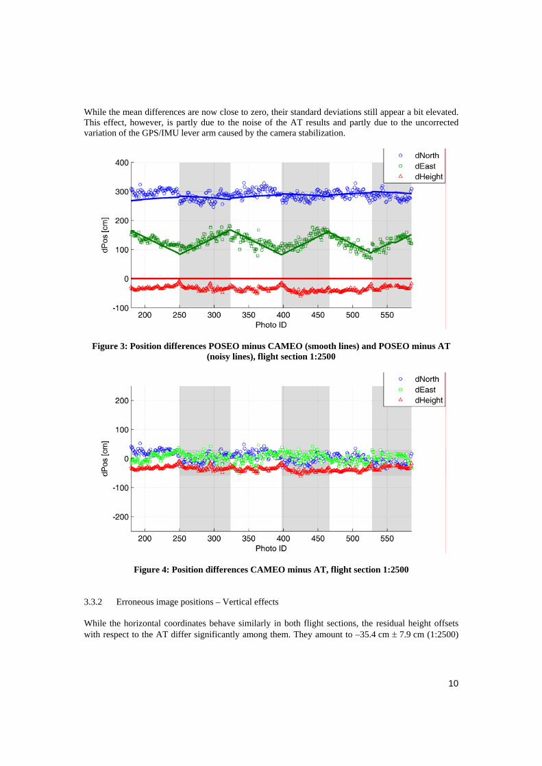
While the mean differences are now close to zero, their standard deviations still appear a bit elevated. This effect, however, is partly due to the noise of the AT results and partly due to the uncorrected variation of the GPS/IMU lever arm caused by the camera stabilization.
Figure 3: Position differences POSEO minus CAMEO (smooth lines) and POSEO minus AT (noisy lines), flight section 1:2500
Figure 4: Position differences CAMEO minus AT, flight section 1:2500
3.3.2 Erroneous image positions – Vertical effects
While the horizontal coordinates behave similarly in both flight sections, the residual height offsets with respect to the AT differ significantly among them. They amount to –35.4 cm ± 7.9 cm (1:2500)
10
and –26.3 cm ± 12.4 cm (1:4000), respectively. This apparent inconsistency is, in fact, a very important finding. There are two sources for this inconsistency:
1. The geoid height in the project area.
2. The vertical distortion of direct georeferencing due to the length distortion of the map projection.
Application of geoid undulation
The mean value of the geoid height is approximately –40 cm and its variation across the project area may be ignored in this investigation. Since its effect is the same for the two flight sections, it does not explain the significant differences of their respective mean-height residuals. After application of the average geoid height the mean residual differences become +4.6 cm (1:2500) and +13.7 cm (1:4000), respectively.
Correction of residual vertical distortions
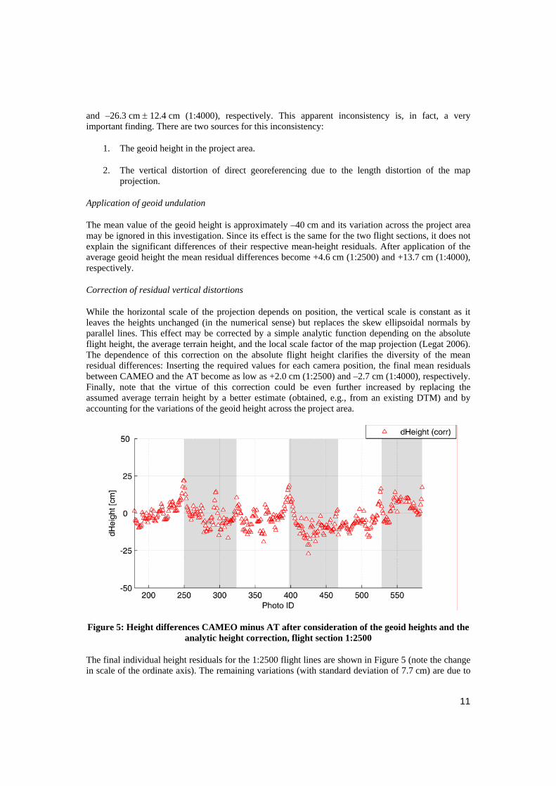
While the horizontal scale of the projection depends on position, the vertical scale is constant as it leaves the heights unchanged (in the numerical sense) but replaces the skew ellipsoidal normals by parallel lines. This effect may be corrected by a simple analytic function depending on the absolute flight height, the average terrain height, and the local scale factor of the map projection (Legat 2006). The dependence of this correction on the absolute flight height clarifies the diversity of the mean residual differences: Inserting the required values for each camera position, the final mean residuals between CAMEO and the AT become as low as +2.0 cm (1:2500) and –2.7 cm (1:4000), respectively. Finally, note that the virtue of this correction could be even further increased by replacing the assumed average terrain height by a better estimate (obtained, e.g., from an existing DTM) and by accounting for the variations of the geoid height across the project area.
Figure 5: Height differences CAMEO minus AT after consideration of the geoid heights and the analytic height correction, flight section 1:2500
The final individual height residuals for the 1:2500 flight lines are shown in Figure 5 (note the change in scale of the ordinate axis). The remaining variations (with standard deviation of 7.7 cm) are due to
11
residual errors in the GPS/INS and AT results. They are in accordance with the accuracy expectations (i.e., it appears that there are no additional undetected gross errors in either of the two data sources).
3.3.3 Erroneous image-orientation angles
In photogrammetry, the orientation of an image is conventionally described by three Euler-angles denoted as omega (ω), phi (φ), and kappa (κ). Actually, the physical units of the angles and the order of individual rotations differ among commercial AT software packages. In particular, Match AT expects grads (gons) and adopts the definition omega-phi-kappa as the primary-secondary-tertiary rotations about axis 1, 2, and 3 of the terrain frame, respectively. This definition differs from that in POSProc.
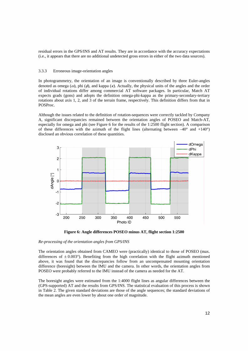
Although the issues related to the definition of rotation-sequences were correctly tackled by Company A, significant discrepancies remained between the orientation angles of POSEO and Match-AT, especially for omega and phi (see Figure 6 for the results of the 1:2500 flight section). A comparison of these differences with the azimuth of the flight lines (alternating between –40° and +140°) disclosed an obvious correlation of these quantities.
Figure 6: Angle differences POSEO minus AT, flight section 1:2500
Re-processing of the orientation angles from GPS/INS
The orientation angles obtained from CAMEO were (practically) identical to those of POSEO (max. differences of ± 0.003°). Benefiting from the high correlation with the flight azimuth mentioned above, it was found that the discrepancies follow from an uncompensated mounting orientation difference (boresight) between the IMU and the camera. In other words, the orientation angles from POSEO were probably referred to the IMU instead of the camera as needed for the AT.
The boresight angles were estimated from the 1:4000 flight lines as angular differences between the (GPS-supported) AT and the results from GPS/INS. The statistical evaluation of this process is shown in Table 2. The given standard deviations are those of the angle sequences; the standard deviations of the mean angles are even lower by about one order of magnitude.
12

Boresight angle Mean [°] Rms [°] About axis 1 (IMU) 1.191 0.0114 About axis 2 (IMU) 1.864 0.0085 About axis 3 (IMU) 0.002 0.0055
Table 2: Mean boresight angles and standard deviations, flight section 1:4000
As follows from the low standard deviations, these angles are well estimated. Once they are applied to the GPS/INS results in the 1:2500 profiles, the newly determined angles agree very well with those provided by the AT as demonstrated by Figure 7. Note the different scale of the ordinate axis compared to the previous figure. The RMS values for the angle differences amount to 0.01° for omega, phi and 0.006° for kappa, respectively. This magnitude of the residuals approximately cor-responds to the expected angular accuracy of the IMU (LN-200) used by Company A. Similar level of agreement between GPS/INS-AT is reached in the experimental setup reported by Madani and Mostafa (2002). Also in this case, the reduced noise level of the kappa difference is probably due to its higher accuracy in the AT (about two times better than for omega and phi).
Figure 7: Boresight-corrected angle differences CAMEO minus Match AT, flight section 1:2500
3.4 Summary
As was shown in the previous sections, the direct- and indirect-georeferencing results of this project fit together very well once the processing is performed correctly. This confirms the expected benefits of the direct approach which provides a significant improvement of economy by reducing the number of GCPs to a minimum suitable for quality control and by speeding up the overall process when AT is necessary due to project requirements.
13

4 Conclusions and recommendations
The following recommendations represent a synthesis of the experiences gained through this project as well as many others within more than ten-year use of direct georeferencing. Nevertheless, these recommendations should not be used blindly and are not intended to replace but rather to complete the existing manuals and suggested measures recommended by the technology providers.
Boresight and lever-arm calibration
The IMU/sensor orientation offset (boresight) must be carefully calibrated. In case of a frame-camera, the calibration requires specific flight patterns and block configuration. The support by GCPs is not required for this purpose. The position offsets between the IMU, the GPS antenna, and the camera should be determined by terrestrial geodetic measurements, ideally after a flight for tactical-grade IMUs. See Kresse et al. (2006) for details.
Gyro-stabilized mount
The gyro stabilization of the camera (or other image sensor) should either be deactivated or the imposed gimbal angles should be recorded. Only in these two cases, the lever arm between the GPS antenna and the IMU can be correctly accounted for. Otherwise, it creates undesirable influences within GPS/INS integration and introduces positioning errors in the subsequent transfer of the results to the sensor EO.
EO transformation to national coordinates
When transforming the EO data derived from GPS/INS to national coordinates, the correct datum definition and map projection are required. In this context, the situation of some countries is very specific as their non-standard map projections may not be supported by provided software packages. Such a situation requires the use of specific transformation tools like CAMEO or the extension of commercial software packages like POSEO. The same is true for the treatment of the systematic residual height errors of direct georeferencing (Legat 2006).
Aero triangulation
When the GPS/INS processing is done carefully, the GPS drift correction within the AT software must be deactivated. The GPS/INS positions will fit to within some 10 cm if the lever arm was correctly treated, at least in the horizontal plane. As mentioned above, the vertical direction will require some additional corrections if the terrain is difficult and if the average terrain and flight heights are great. Lever arms and orientation differences among the sensors should be calibrated and applied prior to the AT.
As was shown in the previous section, the EO elements from direct georeferencing fit very well with those from indirect georeferencing. Thus, it is very beneficial to use the GPS/INS results not only as initial orientation estimates but also to broaden the applications field where the AT is completely dispensable and no GCPs are required. Nevertheless, one should always take counter-measures against possible systematic errors in the GPS/INS data that cannot be determined by filtering and smoothing due to the complementary error behavior of these navigation systems (Skaloud 2006).
14

Acknowledgments
The data used in this study have been provided by the Sihlwald Data Center at the Department of Geography, University of Zurich (www.sihlwald.unizh.ch). The authors are grateful to the Austrian Science Fund (FWF) for financing the research fellowship of Dr. Legat at the TOPO lab of the EPFL from June 2005 until September 2006 under contract number J2460-N10.
References
Kremer, J., 2006. System Calibration of Aerial Camera/GPS/IMU Systems – Procedures and Experiences. Proceedings of the International Calibration and Orientation Workshop EuroCOW, Castelldefels, Spain, 25-27 January: 6 pages (on CDROM).
Kresse, W., Skaloud, J., Hinsken, L., 2006. Requirements for an orientation and calibration standard for digital aerial cameras and related sensors. “From Sensors to Imagery“ – Symposium of ISPRS Commission 1, Paris, 3-6 July. http://topo.epfl.ch/personnes/jsk/Papers/ISPRS06_Paris_KresseSkaloud.pdf
Legat, K., 2006. Approximate direct georeferencing in national coordinates. ISPRS Journal of Photogrammetry & Remote Sensing 60: 239-255. http://topo.epfl.ch/documents/EuroSDR/legat05.pdf
Madani, M., Mostafa, M., 2002. ISAT Direct Exterior QA/QC Strategy Using POS Data. In: Heipke, C., Jacobsen, K., Wegmann, H. (Eds.): OEEPE Official Publication No 43: Integrated Sensor Orientation – Test Report and Workshop Proceedings, 281-297. http://www.eurosdr.net/publications/43.pdf
Madani, M., 2004. Photogrammetric applications, In: McGlone, J.C., Mikhail, E.M., Bethel, J., Mullen, R. (Eds.): Manual of Photogrammetry, 5th edition. American Society of Photogrammetry and Remote Sensing, Bethesda, MA: 1015-1026.
Skaloud, J., Schaer, P., 2003. Towards a more rigorous boresight calibration. ISPRS International Workshop on Theory, Technology and Realities of Inertial/GPS/Sensor Orientation, Castelldefels, Spain. http://topo.epfl.ch/personnes/jsk/Papers/ISPRS_Boresight.pdf
Skaloud, J., 2006. Reliability of Direct Georeferencing Phase 1: An Overview of the Current Approaches and Possibilities. In: EuroSDR Official Publication No 51: Checking and Improving of Digital Terrain Models / Reliability of Direct Georeferencing. http://www.eurosdr.net/publications/51.pdf
Skaloud, J., Legat, K., 2006. CAMEO – Camera Exterior Orientation by Direct Georeferencing. Licensed software, Geodetic Engineering Laboratory (TOPO), Swiss Federal Institute of Technology Lausanne (EPFL), Switzerland. http://topo.epfl.ch/research/techtransfer/
Skaloud, J., Lichti, D., 2006. Rigorous approach to boresight self-calibration in airborne laser scanning. ISPRS Journal of Photogrammetry & Remote Sensing 61 (2006) 47-59. http://topo.epfl.ch/documents/EuroSDR/skaloud05.pdf
15

Index of Figures
Figure 1: Overview of the 1:4000 and 1:2500 flight lines and object point distribution ........................ 7 Figure 2: Position differences POSEO minus AT, flight section 1:2500 ............................................... 8 Figure 3: Position differences POSEO minus CAMEO (smooth lines) and POSEO minus AT (noisy
lines), flight section 1:2500 .................................................................................................... 10 Figure 4: Position differences CAMEO minus AT, flight section 1:2500............................................ 10 Figure 5: Height differences CAMEO minus AT after consideration of the geoid heights and the
analytic height correction, flight section 1:2500 .................................................................... 11 Figure 6: Angle differences POSEO minus AT, flight section 1:2500................................................. 12 Figure 7: Boresight-corrected angle differences CAMEO minus Match AT, flight section 1:2500..... 13
Index of Tables
Table 1: GPS position bias per line as estimated by Match-AT for the 1:2500 flight ............................ 8 Table 2: Mean boresight angles and standard deviations, flight section 1:4000................................... 13
16