EUROCONTROL EXPERIMENTAL CENTRE · PDF filePLC Planning controller INI Initial controller...
65
The information contained in this document is the property of the EUROCONTROL Agency and no part should be reproduced in any form without the Agency’s permission. The views expressed herein do not necessarily reflect the official views or policy of the Agency. EUROPEAN ORGANISATION FOR THE SAFETY OF AIR NAVIGATION EUROCONTROL EXPERIMENTAL CENTRE AIRBORNE SPACING IN THE TERMINAL AREA: CONTROLLER EXPERIMENTS ON MIXED EQUIPAGE, ABNORMAL SITUATIONS AND TRANSITION EEC Note No. 24/06 Project: CoSpace Issued: December 2006 EUROCONTROL
Transcript of EUROCONTROL EXPERIMENTAL CENTRE · PDF filePLC Planning controller INI Initial controller...

The information contained in this document is the property of the EUROCONTROL Agency and no part should be reproduced in any form without the Agency’s permission.
The views expressed herein do not necessarily reflect the official views or policy of the Agency.
EUROPEAN ORGANISATION FOR THE SAFETY OF AIR NAVIGATION
EUROCONTROL EXPERIMENTAL CENTRE
AIRBORNE SPACING IN THE TERMINAL AREA: CONTROLLER EXPERIMENTS ON MIXED EQUIPAGE, ABNORMAL SITUATIONS AND TRANSITION
EEC Note No. 24/06
Project: CoSpace
Issued: December 2006
EUROCONTROL


REPORT DOCUMENTATION PAGE
Reference: EEC Note No. 24/06
Security Classification: Unclassified
Originator: EEC – ATC Research Area
Originator (Corporate Author) Name/Location: EUROCONTROL Experimental Centre Centre de Bois des Bordes B.P.15 F – 91222 Brétigny-sur-Orge CEDEX FRANCE Telephone: +33 (0)1 69 88 75 00 WEB Site: www.eurocontrol.int
Sponsor: EUROCONTROL EATM CASCADE programme EC DGTREN NUPII programme
Sponsor (Contract Authority) Name/Location: EUROCONTROL Agency 96 rue de la Fusée B-1130 BRUXELLES Telephone: +32 2 729 9011 WEB Site: www.eurocontrol.int
TITLE: AIRBORNE SPACING IN THE TERMINAL AREA:
CONTROLLER EXPERIMENTS ON MIXED EQUIPAGE, ABNORMAL SITUATIONS AND TRANSITION
Authors Ludovic Boursier (DSNA), Bruno
Favennec, Eric Hoffman, Laurence Rognin (Steria), Aymeric Trzmiel (Steria), François Vergne, Karim
Zeghal
Date
Dec 2006 Pages
65 Figures
57 Tables
1 Annexes
- References
-
Project
CoSpace Task No. Sponsor
Period
2005-2006
Distribution Statement:
Descriptors (keywords): Airborne separation assistance system (ASAS), Airborne spacing (ASPA), sequencing and merging (S&M), Automatic Dependant Surveillance – Broadcast (ADS-B), terminal area (TMA), area navigation (RNAV), continuous descent (CDA), abnormal situations
Abstract: A series of small-scale controller experiments was conducted to investigate two aspects: (1) the handling of non-nominal situations when using airborne spacing in the terminal area; (2) the benefits of using the route structure defined for airborne spacing in the terminal area, with no airborne spacing equipped aircraft.
The non-nominal situations considered were: mixed equipage, holding patterns and typical unexpected events (go-around, emergency, radio failure, spacing instructions not correctly executed). Handling mixed equipage and holding patterns was found to be feasible. Recovering from the unexpected events was found less difficult than anticipated and was evaluated as being similar to recovery in today’s operations.
Using the route structure without airborne spacing, heading instructions were no longer used and aircraft remained on lateral navigation mode. Even under high traffic load, the inter-aircraft spacing on final was as accurate as today, while descent profiles were improved. The flow of traffic was more orderly with a contained and predefined dispersion of trajectories.
The route structure is a prerequisite for airborne spacing, and its use (without airborne spacing) could be seen as a preliminary step to prepare the implementation of airborne spacing. It could also be seen as a transition towards the systematic use of area navigation, or as a sound foundation to support further developments (e.g. continuous descent, target time of arrival).

Airborne spacing in TMA: mixed equipage, abnormal situations and transition EUROCONTROL
Project CoSpace – EEC Note No. 24/06 v
TABLE OF CONTENTS
1. INTRODUCTION........................................................................................................... 1
2. EXPERIMENT OBJECTIVES ....................................................................................... 1
3. SESSION I .................................................................................................................... 3 3.1. OBJECTIVE ................................................................................................................. 3 3.2. ORGANISATION AND SETUP..................................................................................... 3 3.3. MIXED ASAS AND NON ASAS EQUIPAGE ................................................................ 4 3.4. ASAS AND HOLDING PATTERNS .............................................................................. 5 3.5. SUMMARY ................................................................................................................... 5
4. SESSION II ................................................................................................................... 7 4.1. OBJECTIVE ................................................................................................................. 7 4.2. ORGANISATION AND SETUP..................................................................................... 7 4.3. INITIAL DATA COLLECTION ON MIXED EQUIPAGE ................................................. 7 4.4. RECOVERY PROCEDURE FOR UNEXPECTED EVENTS ......................................... 9 4.5. SUMMARY ................................................................................................................. 13
5. SESSION III ................................................................................................................ 14 5.1. OBJECTIVE ............................................................................................................... 14 5.2. ORGANISATION AND SETUP................................................................................... 14 5.3. USE OF THE ROUTE STRUCTURE WITHOUT ASAS .............................................. 15 5.4. THREE SEQUENCING LEGS.................................................................................... 19 5.5. TWO SEQUENCING LEGS OF SAME DIRECTION................................................... 21 5.6. SUMMARY ................................................................................................................. 22
6. SESSION IV................................................................................................................ 23 6.1. OBJECTIVE ............................................................................................................... 23 6.2. ORGANISATION AND SETUP................................................................................... 23 6.3. THREE ENTRY POINTS WITH BALANCED TRAFFIC FLOWS................................. 24 6.4. USE OF THE ROUTE STRUCTURE WITH STRONG WIND ..................................... 25 6.5. SUMMARY ................................................................................................................. 28
7. SESSION V................................................................................................................. 29 7.1. OBJECTIVE ............................................................................................................... 29 7.2. MOTIVATION ............................................................................................................. 29 7.3. ORGANISATION AND SETUP................................................................................... 29 7.4. NON PARALLEL SEQUENCING LEGS WITH ASAS................................................. 30 7.5. NON PARALLEL SEQUENCING LEGS WITHOUT ASAS.......................................... 31 7.6. SUMMARY ................................................................................................................. 32
EUROCONTROL Airborne spacing in TMA: mixed equipage, abnormal situations and transition
vi Project CoSpace - EEC Note No. 24/06
8. SESSION VI................................................................................................................ 33 8.1. OBJECTIVE ............................................................................................................... 33 8.2. ORGANISATION AND SETUP................................................................................... 33 8.3. HUMAN FACTORS .................................................................................................... 34 8.4. CONTROLLER ACTIVITY .......................................................................................... 36 8.5. PERFORMANCES ..................................................................................................... 37 8.6. QUALITY OF SERVICE.............................................................................................. 38 8.7. SAFETY ..................................................................................................................... 40 8.8. SUMMARY ................................................................................................................. 40
9. SESSION VII............................................................................................................... 41 9.1. OBJECTIVE ............................................................................................................... 41 9.2. ORGANISATION AND SETUP................................................................................... 41 9.3. CURVED SEQUENCING TRIANGLE......................................................................... 42 9.4. INVERTED SEQUENCING TRIANGLE...................................................................... 44 9.5. SUMMARY ................................................................................................................. 50
10. SESSION VIII.............................................................................................................. 51 10.1. OBJECTIVE ............................................................................................................... 51 10.2. ORGANISATION AND SETUP................................................................................... 51 10.3. HUMAN FACTORS .................................................................................................... 52 10.4. CONTROLLER ACTIVITY .......................................................................................... 53 10.5. PERFORMANCES ..................................................................................................... 54 10.6. QUALITY OF SERVICE.............................................................................................. 54 10.7. SAFETY ..................................................................................................................... 55 10.8. SUMMARY ................................................................................................................. 55
11. AIRBORNE SPACING VS ROUTE STRUCTURE ..................................................... 56
12. CONCLUSIONS.......................................................................................................... 57

Airborne spacing in TMA: mixed equipage, abnormal situations and transition EUROCONTROL
Project CoSpace – EEC Note No. 24/06 vii
ACRONYMS
Abbreviation Definition
ADS-B Automatic Dependant Surveillance – Broadcast AMAN Arrival manager ASAS Airborne separation assistance system ASPA Airborne spacing CDA Continuous descent approach S&M Sequencing and merging TMA Terminal control area
RNAV Area navigation FMS Flight management system
E-TMA Extended TMA IAF Initial approach fix FAF Final approach fix
MCDU Multi purpose control and display unit EXC Executive controller PLC Planning controller INI Initial controller (also denoted approach or pickup) ITM Intermediate controller (also denoted final director or feeder) ILS Instrument landing system
REFERENCES
EUROCONTROL CoSpace: www.eurocontrol.int/eec > Projects > CoSpace
EUROCONTROL Navigation Domain: www.ecacnav.com
EUROCONTROL “Manual for Airspace Planning Volume 2 Section 5 - Terminal Airspace Design Guidelines”, Edition 2.0 -Amendment 1, 2005. EUROCONTROL “RNAV Application in Terminal Airspace: an ATC Operational Perspective”, Edition 2D, 1999.


Airborne spacing in TMA: mixed equipage, abnormal situations and transition EUROCONTROL
Project CoSpace - EEC Note No. 24/06
1
1. INTRODUCTION
The work performed so far in the project has allowed the development and refinement of a set of spacing instructions for sequencing and merging arrival flows of aircraft (ASAS S&M)1. To gradually assess their operational feasibility, potential benefits and limits, two streams of air and ground experiments are being conducted.
The air experiments showed the feasibility of airborne spacing from a flight deck perspective, from initial descent down to final approach.
The ground experiments showed that airborne spacing brings many benefits in the terminal area for merging aircraft flows: increased controller anticipation, very significant reduction in number of instructions, more expeditious and orderly flow of traffic (slight increase of throughput, reduced dispersion of trajectories at low altitude).
The ground experiments however assumed “perfect” conditions (e.g. full ASAS equipage) and no unexpected events (e.g. no go-around). It was decided to investigate non-nominal situations when using airborne spacing in the terminal area. The focus was on the feasibility and the definition of related procedures rather than collecting data. The following situations were considered: mixed ASAS equipage, holding patterns and typical unexpected events (go-around, emergency, radio failure, spacing instructions not correctly executed).
As defined here, airborne spacing requires aircraft to be on lateral navigation mode (FMS). A specific route structure has been defined in the terminal area to expedite or delay aircraft (by path shortening or stretching) while remaining on lateral navigation. It was thus decided to investigate the sole use of the new route structure. The motivation was to propose an intermediate step between today’s operations (open loop radar vectors) and airborne spacing, and to get initial trends on the possible benefits brought by the route structure compared to today’s operations.
The series of experiments was conducted between October 2005 and June 2006, and consisted of eight sessions of two or three days with the same three approach controllers. The document presents the outcomes of each session individually. A last section provides a synthesis of the benefits of airborne spacing compared to the sole use of the route structure.
2. EXPERIMENT OBJECTIVES
The detailed objectives of each session was defined or refined depending on the outcomes of the preceding one. During the first sessions, we addressed non-nominal situations and also considered various configurations (two or three entry points, legs of same or opposite direction, legs parallel or non parallel).
We then gradually moved to the use of the route structure without airborne spacing as it was considered as a promising idea. Various configurations, geometries of legs (straight segments, segments approximating concentric arcs, with or without intermediate points) and conditions (no, moderate and strong wind) were simulated. A high traffic load was used, close to the maximum runway capacity.
The detailed objectives of each session are described in Table 1.
1 Airborne spacing involves a new task allocation between controller and flight crew, envisaged as one possible option to enhance the management of arrival flows. It relies on the ability of the controller to task the flight crew to maintain a given spacing with respect to the preceding aircraft. The motivation is neither to transfer problems nor to give more freedom to the flight crew, but to identify a more effective task distribution beneficial to both parties without modifying responsibility for separation provision. Airborne spacing assumes air-to-air surveillance (ADS-B, Automatic Dependant Surveillance – Broadcast) along with cockpit automation (ASAS, Airborne Separation Assistance System).

EUROCONTROL Airborne spacing in TMA: mixed equipage, abnormal situations and transition
Project CoSpace - EEC Note No. 24/06
2
Table 1. Detailed objectives of the sessions.
Session Objectives ASAS
To investigate the working methods when handling mixed equipage (ASAS and non ASAS). Mixed
I To investigate the working methods when using holding patterns. Full
To collect initial data on mixed ASAS equipage. Mixed
II To refine recovery procedures for unexpected events with ASAS. Full
To investigate the working methods when using the ASAS route structure with no ASAS equipped aircraft. No
To investigate the introduction of a third entry point with its associated sequencing leg. Full III
To investigate the use of two sequencing legs of same direction with a 45° orientation. Full
To investigate the working methods with three entry points and balanced traffic flows. Mixed
IV To investigate the use of the ASAS route structure under strong wind conditions. No
V To investigate a modified route structure allowing continuous descent from initial to final approach. Full / No
VI To perform an initial assessment of the benefits and limits of using the route structure. No
To further improve the method and the descent profiles by introducing a new type of legs approximating circles and by raising altitude. No
VII To investigate a method associated to an “opposite” route structure. This could be considered as a “counter demonstration”. No
To perform an initial quantitative assessment of the method with minor adaptations of the route structure to facilitate the descent. No
VIII To investigate the feasibility, benefits and limits of delivering in advance the complete route. No
Airborne spacing in TMA: mixed equipage, abnormal situations and transition EUROCONTROL
Project CoSpace - EEC Note No. 24/06
3
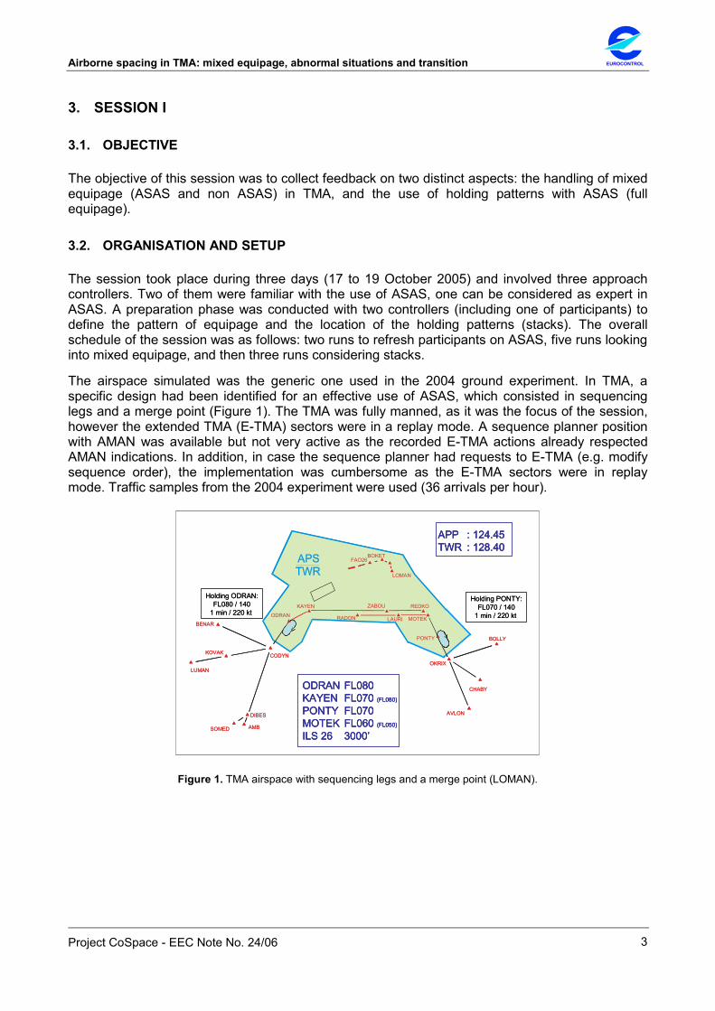
3. SESSION I
3.1. OBJECTIVE
The objective of this session was to collect feedback on two distinct aspects: the handling of mixed equipage (ASAS and non ASAS) in TMA, and the use of holding patterns with ASAS (full equipage).
3.2. ORGANISATION AND SETUP
The session took place during three days (17 to 19 October 2005) and involved three approach controllers. Two of them were familiar with the use of ASAS, one can be considered as expert in ASAS. A preparation phase was conducted with two controllers (including one of participants) to define the pattern of equipage and the location of the holding patterns (stacks). The overall schedule of the session was as follows: two runs to refresh participants on ASAS, five runs looking into mixed equipage, and then three runs considering stacks.
The airspace simulated was the generic one used in the 2004 ground experiment. In TMA, a specific design had been identified for an effective use of ASAS, which consisted in sequencing legs and a merge point (Figure 1). The TMA was fully manned, as it was the focus of the session, however the extended TMA (E-TMA) sectors were in a replay mode. A sequence planner position with AMAN was available but not very active as the recorded E-TMA actions already respected AMAN indications. In addition, in case the sequence planner had requests to E-TMA (e.g. modify sequence order), the implementation was cumbersome as the E-TMA sectors were in replay mode. Traffic samples from the 2004 experiment were used (36 arrivals per hour).
AMB
AVLON
BENAR
BOKET
BOLLY
CODYN
CHABY
DIBES
KOVAK
LOMAN
LUMAN
MOTEKODRAN
OKRIX
SOMED
KAYEN
LAURIRADON
REDKO
PONTY
ZABOU
FAO26
ODRAN FL080KAYEN FL070 (FL080)
PONTY FL070MOTEK FL060 (FL050)
ILS 26 3000’
APP : 124.45 TWR : 128.40
Holding PONTY:FL070 / 140
1 min / 220 kt
Holding ODRAN:FL080 / 140
1 min / 220 kt
AMB
AVLON
BENAR
BOKET
BOLLY
CODYN
CHABY
DIBES
KOVAK
LOMAN
LUMAN
MOTEKODRAN
OKRIX
SOMED
KAYEN
LAURIRADON
REDKO
PONTY
ZABOU
FAO26
ODRAN FL080KAYEN FL070 (FL080)
PONTY FL070MOTEK FL060 (FL050)
ILS 26 3000’
ODRAN FL080KAYEN FL070 (FL080)
PONTY FL070MOTEK FL060 (FL050)
ILS 26 3000’
APP : 124.45 TWR : 128.40 APP : 124.45 TWR : 128.40
Holding PONTY:FL070 / 140
1 min / 220 kt
Holding ODRAN:FL080 / 140
1 min / 220 kt
Figure 1. TMA airspace with sequencing legs and a merge point (LOMAN).

EUROCONTROL Airborne spacing in TMA: mixed equipage, abnormal situations and transition
Project CoSpace - EEC Note No. 24/06
4
3.3. MIXED ASAS AND NON ASAS EQUIPAGE
The TMA was manned by an executive and a planning controller. The sequence planner was present. Three different patterns of traffic were simulated: first aircraft of each cluster at IAF non equipped, clusters (i.e. groups of 2 or 3 aircraft coming from the same IAF) alternatively equipped and non equipped, aircraft randomly equipped. The proportion of equipped aircraft was on average about 50%. All aircraft were equipped to be target (ADS-B out).
A clear distinction on the radar screen between equipped and non equipped aircraft was required. The indication on the progress strip was not enough. An existing ‘highlight’ function (aircraft label, speed vector, current and past positions in yellow) was used to indicate the non equipped aircraft. This served as a strong reminder.
It was clear for all that both equipped and non equipped aircraft should follow the same procedure: sequencing legs and merge point (Figure 2). Indeed, trajectories of aircraft under standard vectoring are no longer compatible with those of aircraft under ASAS (late integration with vectors interfering with early integration with a direct to the merge point). It was observed and reported that almost no vectoring was needed (except one case to recover from a pseudo-pilot mistake): the controllers kept all aircraft (equipped and non equipped) on the sequencing legs and issued direct to the merge point when appropriate. Concerning the ‘direct to’, controllers raised the issue about the (possible) lack of pilot reactivity compared to a vectoring instruction, e.g. due to access to DIR-TO page in the MCDU (situation experienced today when giving a direct to departing aircraft).
Handling mixed ASAS and non ASAS aircraft was found totally feasible. ASAS was used whenever possible as it was found more comfortable, enabling reduced workload and communications. Without ASAS equipped aircraft, the frequency would have been busier and the spacing on final less accurate.
However, non equipped aircraft required more monitoring compared to equipped aircraft or to today situation. The monitoring has to do firstly with issuing at appropriate time the direct to the merge point, secondly, later (in the standard “feeder” area) with managing speed. In particular, the management of speed is made more difficult when the preceding aircraft is under airborne spacing, as its speed is not known precisely. Although closure rate remains small, to prevent from any risk of losing spacing (hence separation), it was suggested to ensure a vertical separation between equipped and non equipped aircraft.
Controllers reported a risk of forgetting to assign speed on final (e.g. 180kt) for non equipped aircraft. They evoked the possibility to allocate a controller for monitoring aircraft after merge, provided that a position would be nevertheless required for monitoring simultaneous approaches.
Concerning the pattern of equipped and non equipped aircraft, two controllers preferred clusters (of equipped and of non equipped) as it is easier to manage speed within a cluster of non equipped aircraft. One controller preferred an alternated pattern of equipage. For all controllers, the equipage had no impact on the definition of the sequence order.
In terms of effectiveness, the spacing at FAF were found less accurate with non equipped aircraft. This (could have) resulted in losing space.

Airborne spacing in TMA: mixed equipage, abnormal situations and transition EUROCONTROL
Project CoSpace - EEC Note No. 24/06
5
3.4. ASAS AND HOLDING PATTERNS
A holding pattern (stack) was defined for each IAF. It was identified that, to ensure every aircraft enters properly the sequencing leg when leaving the stack (avoids overshoot), the stacks had to be located upstream from each leg. One was located at ODRAN (IAF), while for the other, a point (PONTY) had to be created upstream MOTEK (IAF) (Figure 1). All the traffic was ASAS equipped.
In terms of manning, a position dedicated to the management of both stacks (today pickup position) was required, whereas, as identified during the preparation, the planning controller did not seem necessary. Thus, two executive positions (each having its own frequency) were simulated: one for the stacks and the other for final integration with ASAS. AMAN was available but could not be configured to provide reliable indications when using the stacks. The sequence planner role was very limited. The E-TMA was manned by a controller feeding the aircraft in the stacks. ASAS instructions were cancelled by E-TMA prior to entering the stack.
It was identified during the preparation that two flight levels are required for each of the sequencing legs. Indeed, when leaving the same stack, because aircraft had to follow the same trajectory, no lateral separation can be provided, thus a vertical separation is required.
The immediate feedback was that receiving aircraft from the stack and using ASAS was found feasible and comfortable. Stacks with ASAS were found easier than ASAS with no stack or stacks with no ASAS (today situation). Stacks are acknowledged to provide more homogeneous traffic (all aircraft are at same speed, e.g. 220kt, at predefined and stable altitude). In addition, the use of stacks leads to fewer aircraft on the second frequency compared to ASAS with no stack. A typical example of ASAS and stacks is given in Figure 3.
However a difficulty was reported to identify early the final sequence order, due to the lack of accurate knowledge of when aircraft will actually leave the stack (at least in the absence of reliable AMAN indications). Thus, controllers were forced to delay the identification and had to decide the order when aircraft were entering the sequencing leg.
The participants reported that, even when using ASAS, as today, the rate of aircraft leaving the stack had to be adjusted. This adjustment was reported to be difficult to achieve solely by the stack controller (at least in the absence of AMAN).
In terms of effectiveness, with or without ASAS, there is an intrinsic variability in the stack exit conditions, leading to discontinuities and in turn to heterogeneous spacing on final. ASAS and its associated route structure were found very effective to remove these discontinuities and to provide more predictability.
3.5. SUMMARY
The overall feeling was positive: handling mixed equipage or holding patterns with ASAS was found easier than anticipated. The proposed working methods were found to be effective. The next session will consist in an initial measurement of benefits with mixed equipage, and definition of recovery procedures.

EUROCONTROL Airborne spacing in TMA: mixed equipage, abnormal situations and transition
Project CoSpace - EEC Note No. 24/06
6
Figure 2. Typical mixed equipage situation. Aircraft in yellow are non equipped. It can be noticed that all aircraft are following the same procedure (on sequencing leg then direct to merge point).
Figure 3. Typical situation with ASAS and holding patterns. Three aircraft are holding in each.

Airborne spacing in TMA: mixed equipage, abnormal situations and transition EUROCONTROL
Project CoSpace - EEC Note No. 24/06
7
4. SESSION II
4.1. OBJECTIVE
The previous session investigated the working methods when handling mixed equipage (ASAS and non ASAS) and when using holding patterns (full equipage). The objective of the present session was twofold: to go a step further on mixed equipage by collecting initial data, and to refine recovery procedures for unexpected events with full ASAS equipage.
4.2. ORGANISATION AND SETUP
The session took place during three days (14 to 16 November 2005) and involved the three approach controllers who participated in the previous session. A preparation phase was conducted with two controllers (including one of the participants) to define the pattern of equipage and the non nominal situations. The overall schedule of the session was as follows: five runs dedicated to mixed equipage (one baseline without ASAS, one with full equipage and three with a 50% mixed equipage) and three runs with non nominal situations.
The simulated airspace was similar to the one used during the previous session. It consisted of a TMA sector (fully manned) and E-TMA sectors (in a replay mode). In TMA, a specific design had been identified for an effective use of ASAS, which consisted in sequencing legs and a merge point (Figure 4). Compared to the previous session, and following controller comments, the 1000ft between the sequencing legs have been increased to 2000ft in order to provide a spare flight level. A sequence planner position with AMAN was available but not very active as the recorded E-TMA actions already respected AMAN indications. The traffic samples from the previous session were used (36 arrivals per hour).
AMB
AVLON
BENAR
BOKET
BOLLY
CODYN
CHABY
DIBES
KOVAK
LOMAN
LUMAN
MOTEKODRAN
OKRIX
SOMED
KAYEN
LAURIRADON
REDKO
PONTY
ZABOU
FAO26
APP : 124.45 TWR : 128.40
Holding ODRAN:FL080 / 140
1 min / 220 kt
Holding PONTY:FL060 / 140
1 min / 220 kt
ODRAN FL080KAYEN FL080 (FL090)
PONTY FL060MOTEK FL060 (FL070)
ILS 26 3000’AMB
AVLON
BENAR
BOKET
BOLLY
CODYN
CHABY
DIBES
KOVAK
LOMAN
LUMAN
MOTEKODRAN
OKRIX
SOMED
KAYEN
LAURIRADON
REDKO
PONTY
ZABOU
FAO26
APP : 124.45 TWR : 128.40 APP : 124.45 TWR : 128.40
Holding ODRAN:FL080 / 140
1 min / 220 kt
Holding PONTY:FL060 / 140
1 min / 220 kt
ODRAN FL080KAYEN FL080 (FL090)
PONTY FL060MOTEK FL060 (FL070)
ILS 26 3000’
ODRAN FL080KAYEN FL080 (FL090)
PONTY FL060MOTEK FL060 (FL070)
ILS 26 3000’
Figure 4. TMA airspace with sequencing legs and a merge point (LOMAN).
4.3. INITIAL DATA COLLECTION ON MIXED EQUIPAGE
Since the handling of mixed equipage was found totally feasible in the previous session, the objective was to get initial trends.
The TMA was manned by an executive (EXC) and a planning controller (PLC) for the mixed (50% randomly equipped) and full equipage runs, and by a pickup (INI) and a feeder (ITM) position for

EUROCONTROL Airborne spacing in TMA: mixed equipage, abnormal situations and transition
Project CoSpace - EEC Note No. 24/06
8
the baseline without ASAS. All aircraft were equipped to be target (ADS-B out). In addition to a marking on the progress strip, an existing ‘highlight’ function (aircraft label in yellow) was used to indicate the non equipped aircraft (Figure 5).
Figure 5. Controller interface in a mixed equipage situation showing spacing links (orange for target selection, green
when under airborne spacing) and highlights (in yellow) of non ASAS equipped aircraft.
The previous session showed that having distinct procedures for equipped and non equipped aircraft (respectively sequencing legs with merge point and open loop radar vectoring as in today’s operations) was incompatible. Thus, the only way (identified) to handle mixed equipage was for the non equipped aircraft to follow the equipped aircraft procedure: controllers kept the non equipped aircraft on the sequencing legs and when appropriate issued a ‘direct-to’ the merge point. This procedure was used also in the run with no equipped aircraft as it was found useful.
Similarly to the previous session, controllers reported that handling mixed ASAS and non ASAS aircraft was entirely feasible. However, non equipped aircraft required more monitoring compared to equipped aircraft or to today situation. According to the controllers, the settings of the radar display (zoom) used by the EXC was not adapted to perform radar monitoring close to ILS (for wake turbulence separations or simultaneous approaches if applicable). Thus, in the condition ASAS 50%, the controllers felt a loss of precision achieved at the FAF compared to full ASAS equipage. To better distribute the workload between the controllers as well as improving monitoring and spacing accuracy on final, the controllers recommended the use of two frequencies (INI and ITM as today). The sequence order was decided according to the position of the flights and not according to the aircraft equipment (i.e. ASAS or not) as it is more convenient to follow the “natural” arrival order. The spare flight level per sequencing leg was found useful (as a backup), despite a slightly larger speed differences between the default flight levels (10kt in ground speed with 2000ft, compared to 5kt with 1000ft).
Despite the limited number of exercises (one for 100%, three for 50% and three for 0% equipped aircraft), initial trends can be observed which suggest that 50% equipped aircraft already brings some benefits compared to 0%, although not as much as with 100%: reduction in the number of manoeuvre instructions (Figure 6) and more accurate inter aircraft spacing on final (Figure 7).

Airborne spacing in TMA: mixed equipage, abnormal situations and transition EUROCONTROL
Project CoSpace - EEC Note No. 24/06
9
Concerning the manoeuvre instructions, with 100% and even with 50% equipped aircraft, the reduction can be observed for speed and direct. This is due to the fact that the controller had to sequence non equipped aircraft with one direct to the merge point and then with speed instructions, in comparison with one spacing instruction to sequence equipped aircraft. Concerning the inter aircraft spacing, a reduced dispersion around the required inter aircraft spacing can be observed with 100% and even with 50% equipped aircraft.
ASAS 100% ASAS 50%
LevelSpeedDirect/headingSpacing
Manoeuvre instructions
ASAS 0%ASAS 100%ASAS 100% ASAS 50%ASAS 50%
LevelSpeedDirect/headingSpacing
LevelSpeedDirect/headingSpacing
Manoeuvre instructions
ASAS 0%ASAS 0%
Figure 6. Initial trends of manoeuvre instructions.
ASAS 100%ASAS 50%ASAS 0%
Inter aircraft spacing at final approach fix
907050 110 170130 150
seconds
ASAS 100%ASAS 50%ASAS 0%
Inter aircraft spacing at final approach fix
907050 110 170130 150
seconds
Figure 7. Initial trends for spacing on final.
In Figure 7, the inter aircraft spacing was normalised at 90 when the required spacing was 120 seconds.
4.4. RECOVERY PROCEDURE FOR UNEXPECTED EVENTS
The motivation was to refine procedure – not to assess the detection capability of the controllers. For that purpose, prior to the runs, situations were described and an initial recovery procedure was agreed. During the runs, controllers could ask to freeze the simulation to discuss the procedure.
The unexpected events selected were those raised during controller experiments and safety sessions (HAZOP) requiring a dedicated recovery procedure. The selected events were: go-around, emergency, radio failure and two cases of a spacing instruction not correctly executed resulting in an infringement of the required spacing (and separation). The events were simulated as follows:
• Run 1: emergency (one occurrence), speed not reduced during “merge” (two occurrences), “merge” performed instead of “heading then merge” (two occurrences).
• Run 2: radio failure (one occurrence), “merge” performed instead of “heading then merge” (two occurrences).
• Run 3: go-around, emergency (one occurrence each).
The TMA was manned by an executive and a planning controller. When required, it was possible to open a second frequency in order to have two executive controllers (pickup and feeder). In that case the sequence planner would also have to handle coordinations with E-TMA.

EUROCONTROL Airborne spacing in TMA: mixed equipage, abnormal situations and transition
Project CoSpace - EEC Note No. 24/06
10
4.4.1. Go-around
The go-around occurred while in contact with the tower (i.e. aircraft on the ILS and no more in contact with the TMA executive controller). The tower was not manned, however in order to get realistic situations, the appropriate co-ordinations and actions were simulated.
Handling this situation was not found more difficult than with current practices. The controllers could easily identify where to re-integrate the aircraft in the sequence and quickly get back to a nominal situation.
The refined standard procedure is to join one IAF in order to complete a new approach using the sequencing legs and when appropriate spacing instructions. This requires re-integrating the aircraft in a sequence of aircraft possibly with a target selected or under airborne spacing (which implies deselecting a target or cancelling an existing spacing instruction, then issuing two new spacing instructions).
However, in some cases, and according to the traffic situation, the aircraft can be re-integrated before the IAF, for instance by being vectored to a track parallel to the sequencing legs (Figure 8).
As today, the aircraft will have to be transferred early enough to the TMA in order to be re-integrated in the sequence as soon as possible. Early speed reductions could be requested to E-TMA to ease the re-insertion of the aircraft into the sequence. Depending on traffic conditions, holding patterns may be opened.
Figure 8. Go-around. The aircraft (AF890VK) is re-integrated into the sequence (target selected).
Airborne spacing in TMA: mixed equipage, abnormal situations and transition EUROCONTROL
Project CoSpace - EEC Note No. 24/06
11
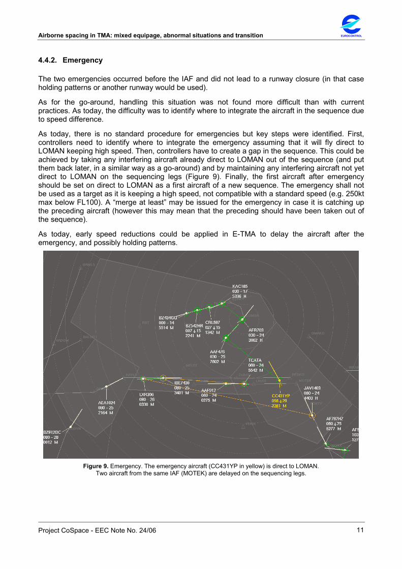
4.4.2. Emergency
The two emergencies occurred before the IAF and did not lead to a runway closure (in that case holding patterns or another runway would be used).
As for the go-around, handling this situation was not found more difficult than with current practices. As today, the difficulty was to identify where to integrate the aircraft in the sequence due to speed difference.
As today, there is no standard procedure for emergencies but key steps were identified. First, controllers need to identify where to integrate the emergency assuming that it will fly direct to LOMAN keeping high speed. Then, controllers have to create a gap in the sequence. This could be achieved by taking any interfering aircraft already direct to LOMAN out of the sequence (and put them back later, in a similar way as a go-around) and by maintaining any interfering aircraft not yet direct to LOMAN on the sequencing legs (Figure 9). Finally, the first aircraft after emergency should be set on direct to LOMAN as a first aircraft of a new sequence. The emergency shall not be used as a target as it is keeping a high speed, not compatible with a standard speed (e.g. 250kt max below FL100). A “merge at least” may be issued for the emergency in case it is catching up the preceding aircraft (however this may mean that the preceding should have been taken out of the sequence).
As today, early speed reductions could be applied in E-TMA to delay the aircraft after the emergency, and possibly holding patterns.
Figure 9. Emergency. The emergency aircraft (CC431YP in yellow) is direct to LOMAN.
Two aircraft from the same IAF (MOTEK) are delayed on the sequencing legs.
EUROCONTROL Airborne spacing in TMA: mixed equipage, abnormal situations and transition
Project CoSpace - EEC Note No. 24/06
12
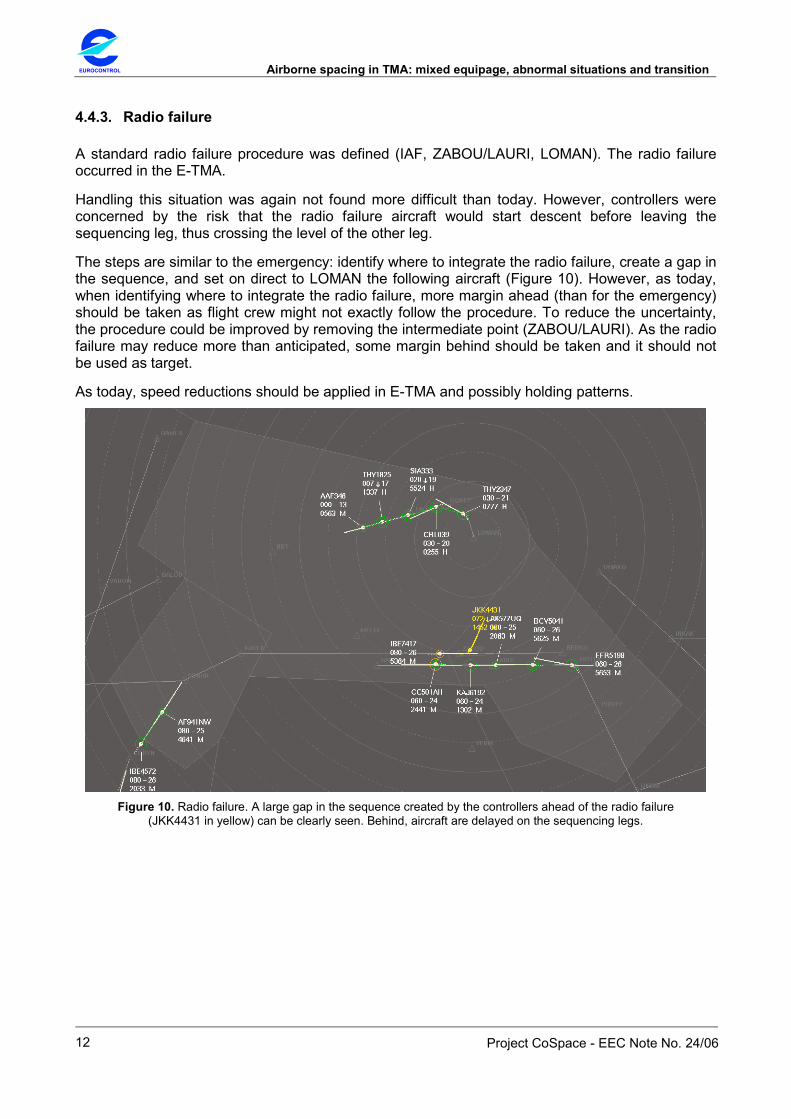
4.4.3. Radio failure
A standard radio failure procedure was defined (IAF, ZABOU/LAURI, LOMAN). The radio failure occurred in the E-TMA.
Handling this situation was again not found more difficult than today. However, controllers were concerned by the risk that the radio failure aircraft would start descent before leaving the sequencing leg, thus crossing the level of the other leg.
The steps are similar to the emergency: identify where to integrate the radio failure, create a gap in the sequence, and set on direct to LOMAN the following aircraft (Figure 10). However, as today, when identifying where to integrate the radio failure, more margin ahead (than for the emergency) should be taken as flight crew might not exactly follow the procedure. To reduce the uncertainty, the procedure could be improved by removing the intermediate point (ZABOU/LAURI). As the radio failure may reduce more than anticipated, some margin behind should be taken and it should not be used as target.
As today, speed reductions should be applied in E-TMA and possibly holding patterns.
Figure 10. Radio failure. A large gap in the sequence created by the controllers ahead of the radio failure
(JKK4431 in yellow) can be clearly seen. Behind, aircraft are delayed on the sequencing legs.

Airborne spacing in TMA: mixed equipage, abnormal situations and transition EUROCONTROL
Project CoSpace - EEC Note No. 24/06
13
4.4.4. Spacing instruction not correctly executed
Two situations simulated one aircraft (under airborne spacing) catching-up with its target.
These situations were not rated as serious cases by the controllers: they should be quickly detected through usual radar monitoring and easy to handle. The recovery procedure could be described as follows: first, issue a “cancel spacing” along with a speed reduction, then if appropriate re-select target (when not retained) and re-issue a spacing instruction (generally “merge”). In case aircraft are too close (e.g. about to infringe separation) due to a very late detection (rated as unlikely to occur), further actions are required. First, take the aircraft out of the sequence. Then:
• If no aircraft under airborne spacing behind: vector the “non compliant” aircraft on a track parallel to the sequencing legs and, when appropriate, re-select target and re-issue a spacing instruction (generally “continue heading then merge”).
• Otherwise: “cancel spacing” for the following aircraft (now number one of a new sequence) and handle the “non compliant” aircraft similarly to a go-around situation.
Four “continue heading then merge” instructions were correctly read-back by the pseudo pilots but intentionally executed as “merge” instructions.
With every case the mistake was detected very quickly and was found easy to handle by the controllers.
In such cases, the recovery procedure as discussed by the controllers could be described as follows: first, issue to the “non compliant” aircraft a “cancel spacing, retain target” along with speed instructions (generally 220kt). Then, vector the aircraft on a track parallel to the sequencing legs. Finally, issue a new spacing instruction (generally “continue heading then merge”).
4.5. SUMMARY
In applying the ASAS procedure for non ASAS aircraft, handling mixed equipage was found to be entirely feasible. However, non ASAS aircraft required more monitoring and controllers recommended the use of two frequencies. Initial trends suggest that 50% equipped aircraft already brings some benefits compared to 0% (reduction in the number of manoeuvre instructions and more accurate inter aircraft spacing on final) although not as much as with 100%.
The various unexpected events were found less difficult to handle than initially anticipated. They were in fact evaluated as similar to what is experienced with today’s operations. However, the general principle to handle such situations when using spacing instructions is to “isolate” the aircraft experiencing the problem (i.e. take it out of the sequence) and not to act on the whole sequence.
EUROCONTROL Airborne spacing in TMA: mixed equipage, abnormal situations and transition
Project CoSpace - EEC Note No. 24/06
14
5. SESSION III
5.1. OBJECTIVE
The objective of the previous session was to collect initial data on mixed ASAS equipage and to refine recovery procedures for non nominal situations with ASAS (full equipage).
The objective of the present session was to explore:
• The working methods when using the ASAS route structure with no ASAS equipped aircraft.
• The introduction of a third entry point with its associated sequencing leg (full ASAS equipage).
• The use of two sequencing legs of same direction with a 45° orientation (full ASAS equipage).
5.2. ORGANISATION AND SETUP
The session took place during three days (12 to 14 December 2005) and involved the three approach controllers (one of them only the last day) who participated to the previous sessions. A preparation phase was conducted with two controllers (including one of participants) to define the modified route structure, the traffic samples and the wind conditions. The session consisted of four runs with no ASAS aircraft (including two runs with wind), four runs with the third entry point (full ASAS equipage), and four runs with the sequencing legs of same direction (full ASAS equipage).
The simulated airspace was the one used during the previous session. It consisted of a TMA sector and E-TMA sectors (in a replay mode). In TMA, a specific design had been identified for an effective use of ASAS, which consisted of two parallel sequencing legs (2000ft vertical separation, 2nm apart) and a merge point. A sequence planner position with AMAN was available but not used as the recorded E-TMA actions already respected AMAN indications. The traffic samples from the previous sessions were used (36 arrivals per hour). Following the recommendations from the previous sessions, the TMA had two positions (frequencies) as today: initial (pick-up) with an executive and a planning controller, and intermediate (feeder) with an executive controller. With every run, it was decided to use the complete phraseology (announcement of ILS, indication of QNH value) in order to better reflect the actual conditions.

Airborne spacing in TMA: mixed equipage, abnormal situations and transition EUROCONTROL
Project CoSpace - EEC Note No. 24/06
15
5.3. USE OF THE ROUTE STRUCTURE WITHOUT ASAS
The motivation for investigating the use of the ASAS route structure with no ASAS aircraft was twofold: to propose an intermediate step between today operations (open loop radar vectors) and ASAS; to get initial trends on the possible benefits brought by the route structure, in particular under wind conditions.
The simulated airspace is shown in Figure 11. In the two last runs, the wind was: 270°/20kt on the ground, 270°/35kt along the sequencing legs2.
AMB
AVLON
BENAR
BOKET
BOLLY
CODYN
CHABY
DIBES
KOVAK
LOMAN
LUMAN
MOTEKODRAN
OKRIX
SOMED
KAYEN
LAURIRADON
REDKO
PONTY
ZABOU
FAO26
Holding ODRAN:FL080 / 140
1 min / 220 kt
Holding PONTY:FL060 / 140
1 min / 220 kt
ODRAN FL080KAYEN FL080 (FL090)
PONTY FL060MOTEK FL060 (FL070)
ILS 26 3000’
ODRAN FL080KAYEN FL080 (FL090)
PONTY FL060MOTEK FL060 (FL070)
ILS 26 3000’
INI : 124.45 ITM : 128.70TWR : 128.40
INI : 124.45 ITM : 128.70TWR : 128.40
Figure 11. TMA airspace with two sequencing legs and a merge point (LOMAN).
The working method (use of direct-to instructions for integration on a point) was found totally feasible and not more difficult than today’s method (use of heading instructions for integration on an axis). However, it is considered as less flexible than today’s method, but more flexible than with ASAS as the choice of the sequence order is less constrained (no aircraft linked and no need to define the sequence order in advance). Controllers reported a reduction of workload, fewer messages than today and no saturation in spite of a complete phraseology.
The working method, along with the two frequencies (as today), allows a clear tasks distribution between initial (INI) and intermediate (ITM) controllers. The task of the INI essentially consisted in achieving homogeneous speeds (e.g. 220kt) when aircraft join the sequencing legs, handling the integration with a direct route to LOMAN, and transferring the aircraft to the ITM. The task of the ITM consisted in maintaining spacing with speed instructions, giving the descent to ILS, and transferring the aircraft to the tower once established on ILS.
With two frequencies, the descent instruction towards LOMAN and the ILS could be delivered later (with a single frequency, the instruction was given when aircraft reported merging, to prevent from forgetting the descent). In addition, the workload between INI and ITM was well balanced, providing more availability and allowing a good monitoring, in particular between the merge point and the ILS. This could benefit to safety. However, the work on ITM position was felt more boring (less fun) than ITM today. With two participants only (no planning controller on INI position during three runs), the situation was not found particularly demanding.
2 Although the wind gradient could be more realistic, it was considered as acceptable for an initial evaluation of wind effects.

EUROCONTROL Airborne spacing in TMA: mixed equipage, abnormal situations and transition
Project CoSpace - EEC Note No. 24/06
16
5.3.1. Without wind
The sequencing task is reflected in the distribution of manoeuvre instructions (Figure 12). The direct-to instructions are given (by the INI) between 40 and 35NM to the Final Approach Fix, and a peak of speed instructions (given by the ITM) is visible between 15 and 5NM. In contrast with today operations, this result shows clear geographical task allocation and transfer conditions between both positions.
Two variants of the working method were observed: reducing aircraft early or late (e.g. 200kts versus 220kts when leaving the legs). The first variant allowed for packing the aircraft early and avoided going too far along the sequencing legs. The second one allowed keeping enough margins for further speed reduction when necessary, but aircraft stayed longer on the legs. The result after the merge point was found very similar.
It can be seen that aircraft trajectories are contained in a triangle composed by the two legs and the merge point (Figure 13). Heading instructions were not used, except for two cases to recover from a direct-to not correctly given or executed (see trajectories in Figure 13).
Num
bero
fin
stru
ction
s
SpeedHeading/Direct
Distance to FAF (NM)
0 5 10 15 20 25 30 35 40 45 50 55 60 65 70 75 80
Num
bero
fin
stru
ction
s
SpeedHeading/DirectSpeedHeading/Direct
Distance to FAF (NM)
0 5 10 15 20 25 30 35 40 45 50 55 60 65 70 75 80
Figure 12. Geographical distribution of manoeuvre
instructions.
No ASASM5_0 TMA
Figure 13. Example of aircraft trajectories.
5.3.2. With wind
A short period of time was required to get used to the wind effect, and then there were only limited differences in comparison to the situation without wind. The situation was found not more difficult than today with a similar wind. The range rings centred over LOMAN were still useful to identify the sequence order (Figure 14).
Two techniques were used, depending on whether the INI compensated for wind effect on the sequencing legs (by achieving same ground speed) or not (by issuing same indicated airspeed, as illustrated in Figure 14). However, according to the controllers, it was clear that with stronger winds, only the second technique (no compensation) would be possible.
These two techniques to handle wind had an impact on controllers’ activity and on aircraft trajectories. The first technique (compensation of the wind effect), induced an increase in the number of speed instructions as in show in Figure 15 left. Indeed, once aircraft were direct to LOMAN, the wind component changed, and the ITM had to issue many speed instructions to harmonize aircraft speeds (a bulk shows up between 5 and 10NM to the FAF). In contrast, the second technique (no compensation of the wind effect), led to more homogenous speeds when the aircraft were direct to LOMAN, resulting in fewer speed instructions (Figure 15, right).

Airborne spacing in TMA: mixed equipage, abnormal situations and transition EUROCONTROL
Project CoSpace - EEC Note No. 24/06
17
In addition, with the first technique, the direct-to instructions are issued earlier (from 75 to 35NM to the FAF) compared to the second one (mainly between 45 and 40NM). From the aircraft trajectories, it can be seen also that, with the second technique, aircraft go farther on the legs (Figure 16). With both techniques, the result after the merge point (spacing accuracy) was found similar. In terms of effectiveness, no clear impact of the wind on inter aircraft spacing on final is visible (Figure 17).
Figure 14. Use of ASAS route structure with no ASAS equipped aircraft (wind condition).
Compensation of wind effect
Num
bero
fin
stru
ction
s
0 5 10 15 20 25 30 35 40 45 50 55 60 65 70 75 80
SpeedHeading/Direct
Distance to FAF (NM)
Compensation of wind effect
Num
bero
fin
stru
ction
s
0 5 10 15 20 25 30 35 40 45 50 55 60 65 70 75 80
SpeedHeading/DirectSpeedHeading/Direct
Distance to FAF (NM)
No compensation of wind effect
Nnu
mbe
rof
inst
ructi
ons
Distance to FAF (NM)
0 5 10 15 20 25 30 35 40 45 50 55 60 65 70 75 80
SpeedHeading/Direct
No compensation of wind effect
Nnu
mbe
rof
inst
ructi
ons
Distance to FAF (NM)
0 5 10 15 20 25 30 35 40 45 50 55 60 65 70 75 80
SpeedHeading/DirectSpeedHeading/Direct
Figure 15. Geographical distribution of manoeuvre instructions. Compensation of wind effect (left) and no compensation (right).

EUROCONTROL Airborne spacing in TMA: mixed equipage, abnormal situations and transition
Project CoSpace - EEC Note No. 24/06
18
No ASAS WM6_0W TMACompensation of wind effect
No ASAS WM6_0W TMACompensation of wind effect
No ASAS WM5_0W TMANo compensation of wind effect
No ASAS WM5_0W TMANo compensation of wind effect
Figure 16. Aircraft trajectories. Compensation of wind effect (left) and no compensation (right).
907050 110 170130 150
Without wind
With wind
seconds
Inter aircraft spacing at final approach fix
907050 110 170130 150907050 110 170130 150
Without wind
With wind
seconds
Inter aircraft spacing at final approach fix
Figure 17. Inter aircraft spacing on final without and with wind (normalised at 90s).
To summarise, without or with (moderate) wind, the working method with no ASAS aircraft was found comfortable, safe and accurate. It seemed as accurate as today’s operations (open loop radar vectors) but less accurate than with ASAS. The method is considered as less flexible than today’s operations, but more flexible than with ASAS. Compared to today’s operations, it also brings other benefits: contained dispersion of trajectories, aircraft on lateral navigation and systematic standard interception of the ILS.
As a moderate wind was considered easy to handle, it was found necessary to evaluate stronger wind conditions (e.g. 50kts along the sequencing legs). It was mentioned that abnormal or degraded situations (e.g. go-around, thunderstorms) will have to be tested.

Airborne spacing in TMA: mixed equipage, abnormal situations and transition EUROCONTROL
Project CoSpace - EEC Note No. 24/06
19
5.4. THREE SEQUENCING LEGS
A third entry point (IAF) was added to handle a minority traffic flow, leading to an increased traffic level of 40 arrivals per hour (20% of heavy). The new IAF (EPERN) was located in the North-East of the arrival runway. A corresponding sequencing leg was defined (GOVIN, NASIG and MORET), parallel and 2nm North to the existing ones (Figure 18).
The merge point (LOMAN) and the standard trajectory to join the runway from there remained unchanged. To optimise aircraft profiles, the principle of flight level allocation on the sequencing legs was revisited: lowest levels for the sequencing leg closest to the landing runway, highest levels for the farthest ones. The flight levels were allocated as follows: FL070 from EPERN, FL090 from ODRAN and FL110 from PONTY. The ILS interception was at 4000 feet (instead of 3000 feet with the previous runs). The new allocation and ILS interception allowed for higher levels on the sequencing legs.
With two participants only (two runs), the TMA was manned by one executive and one planning controller but this situation was very demanding (due to the additional entry point and the increased traffic level). The AMAN was not configured to operate with the third entry point. In contrast with the previous runs (no ASAS), no wind was simulated as it was not (yet) modelled in the ASAS algorithm.
AMB
AVLON
BENAR
BOKET
BOLLY
CODYN
CHABY
DIBES
KOVAK
LOMAN
LUMAN
MOTEKODRAN
OKRIX
SOMED
KAYENLAURIRADON
REDKO
PONTY
ZABOU
FAO26
EPERN
GOVINMORET NASIG
PONTY/MOTEK FL110ODRAN/KAYEN FL090EPERN/GOVIN FL070 ILS 26 4000’
PONTY/MOTEK FL110ODRAN/KAYEN FL090EPERN/GOVIN FL070 ILS 26 4000’
INI : 124.45 ITM : 128.70TWR : 128.40
INI : 124.45 ITM : 128.70TWR : 128.40
Figure 18. TMA airspace with three sequencing legs and a merge point (LOMAN).
The introduction of a third IAF as simulated here was not a problem. This was not really a change compared to the situation with only two IAFs. However, the traffic level was the maximum acceptable.
When flights are using the two “external” sequencing legs (from GOVIN and MOTEK), and due to the distance between these legs (4nm), they diverge quickly as soon as the first one is turning to the merge point. There is consequently a limited amount of time to chain the instructions to these flights. When the third sequencing leg handle a minority flow of traffic, it should be possible to use the leg of same direction (e.g. from MOTEK) but with different flight levels. The situation with balanced traffic level among the three entry points should be tested.
The ILS interception at 4000 feet did not raise any difficulty here. In addition this allowed for a continuous descent from leaving the sequencing legs. The flight level allocation along the sequencing legs was found efficient, and the flight level difference between the external legs was not a problem. However, when the traffic demand is high, with aircraft flying at reduced speed, it

EUROCONTROL Airborne spacing in TMA: mixed equipage, abnormal situations and transition
Project CoSpace - EEC Note No. 24/06
20
was difficult for the flights coming via MOTEK at FL110 to arrange their descent in order to stick with the required levelling off (one minute) prior the ILS interception. The level from MOTEK should be FL100 maximum in order to guarantee a standard interception.
Due to the geometry of the sequencing legs, the ASAS links were mixing and overlapping, mainly at the INI position. Some controllers masked the links and only displayed the circles around the aircraft, thus solely relied on the paper strips for the sequence order (Figure 19).
As for two IAFs, the definition of the sequence order has to be done in advance by the planning controller. With three IAFs, this task is demanding although not particularly difficult. To do so, in addition to the range rings centred on LOMAN, the range&bearing tool was used and centred on REDKO. The range rings were also used for monitoring by INI and ITM.
The use of two frequencies was considered mandatory. However, the general feeling was that the job satisfaction is reduced for the ITM controller who is only on charge of the descent to ILS and the transfer to the tower.
It should be noticed that one unexpected even occurred (descent instruction to ILS forgotten). This event was handled according to the recovery procedures defined during the previous session without any difficulty (aircraft isolated and re-integrated at a further position in the sequence).
Figure 19. Three sequencing legs (no ASAS links displayed, only circles).

Airborne spacing in TMA: mixed equipage, abnormal situations and transition EUROCONTROL
Project CoSpace - EEC Note No. 24/06
21
5.5. TWO SEQUENCING LEGS OF SAME DIRECTION
The motivation of this design was twofold: to mitigate the effects of the wind by considering sequencing legs of same direction; to investigate a different orientation of the legs to cope with constraints (e.g. airport in vicinity, simultaneous parallel approaches).
The routes used during the previous session were kept up to REDKO (from ODRAN) and MOTEK (from PONTY) where they respectively join the new sequencing legs to GREGO and VODUL (Figure 20). The new merge point was MUROK and a route MUROK-LORAC-BOKET was defined to join the ILS. With this route structure, the aircraft had to be over ODRAN at FL110 to join REDKO at FL080. The aircraft had to be over PONTY and MOTEK at FL060. The ILS interception was at 3000 feet. The TMA boundary was modified in order to integrate the new sequencing legs.
As for the previous runs (third entry point), with two participants only (three runs), the TMA was manned by one executive and one planning controller.
AMB
AVLON
BENAR
BOKET
BOLLY
CODYN
CHABY
DIBES
KOVAK
LUMAN
MOTEKODRAN
OKRIX
SOMED
KAYEN REDKO
PONTY
ZABOU
FAO26VODUL
GREGO
MUROKLORAC
ILS
New TMA areaNew TMA area
APP: 124.45(or INI: 124.85 / ITM: 128.70)
TWR: 128.40
ODRAN FL110REDKO FL080 (FL090)
PONTY FL060MOTEK FL060 (FL070)
ILS 26 3000’
ODRAN FL110REDKO FL080 (FL090)
PONTY FL060MOTEK FL060 (FL070)
ILS 26 3000’
Figure 20. TMA airspace with two sequencing legs of same direction and a merge point (MUROK).
During the first run, the flights coming from ODRAN were sent direct to LOMAN before joining the sequencing leg. This prevented from testing the new design. Therefore, for the following runs, it was agreed that every flight coming from ODRAN had to pass over REDKO.
Having two parallel sequencing legs of same direction was considered easier to use than legs of opposite directions. When the flights are along the sequencing legs, it is easy to identify the order from the radar screen and there is no mix of ASAS links (Figure 21). Then, it is easier to initiate or anticipate the turn to the merge point as the flights are progressing to the same direction. In addition, the turns are less sharp and could result in a more accurate spacing. The 45° orientation of the legs did not raise any difficulty.
The identification of the sequence order by the planning controller was more difficult (than with the previous design) due to the dissymmetry of the routes prior the sequencing legs (one long “tangential” from ODRAN and one short “radial” from PONTY). In particular, the planning controller had to wait for aircraft from ODRAN to pass KAYEN. He centred the range rings over a point located between MOTEK and REDKO, while the executive controller centred them over MUROK. As usual, the sequence order proposed by the planning controller should be followed by the executive as he as no time to handle this task.
It should be noticed that two unexpected events occurred (aircraft turning in the wrong direction). As for the previous runs (third entry point), the recovery was executed without any difficulty

EUROCONTROL Airborne spacing in TMA: mixed equipage, abnormal situations and transition
Project CoSpace - EEC Note No. 24/06
22
following the recommendations defined during the previous session (aircraft isolated and re-integrated at a further position in the sequence).
Figure 21. Two sequencing legs of same direction with a 45° orientation.
5.6. SUMMARY
The various situations simulated during this session were found easy to handle. The use of two frequencies allowed a better balance of workload, and a good monitoring near the ILS.
The working method when using the ASAS route structure with no ASAS equipped aircraft was found comfortable, safe and accurate. A moderate wind did not raise specific difficulty compared to today’s operation with similar wind conditions.
The introduction of a third IAF with its sequencing legs did not raise difficulty. Two sequencing legs of same direction with a 45° orientation were considered easier to use than legs of opposite directions (better anticipation and readability of the radar screen).
Finally, the session showed that the route structure could be improved to optimise vertical profiles.
The next session will consider three entry points with balanced traffic level when using mixed ASAS equipage and no ASAS. In addition, with no ASAS, the impact of strong winds will be tested.

Airborne spacing in TMA: mixed equipage, abnormal situations and transition EUROCONTROL
Project CoSpace - EEC Note No. 24/06
23
6. SESSION IV
6.1. OBJECTIVE
The objective of the previous session was to explore (1) the working methods when using the ASAS route structure with no ASAS equipped aircraft (without and with moderate wind); (2) the introduction of a third entry point (one minority flow) with its associated sequencing leg (full ASAS equipage) and (3) the use of two sequencing legs of same direction with a 45° orientation (full ASAS equipage).
The objective of the present session was to investigate:
• The use of three entry points with balanced traffic flows (mixed ASAS equipage).
• The working methods when using the ASAS route structure under strong wind conditions (no ASAS equipped aircraft).
6.2. ORGANISATION AND SETUP
The session took place during two days (30 and 31 January 2006) and involved the three approach controllers who participated to the previous sessions. A preparation phase was conducted with two controllers (including one of participants) to define the traffic samples and the wind conditions. The session consisted of six runs, three for each objective.
The simulated airspace consisted of a TMA sector and E-TMA sectors (in a replay mode). It was the same as the one used during the previous session (three entry points) but with lowered flight levels (1000 feet) on the three sequencing legs to facilitate the final descent (Figure 22). The legs were still separated by 2000ft. The ILS interception was conducted at 4000 feet (instead of 3000 feet previously). To simulate a departure constraint, it was not possible to give direct route to LOMAN before GOVIN (from EPERN) or abeam RADON (from ODRAN).
New traffic samples were used with balanced flows (40 arrivals per hour with 20% of heavy aircraft). Following the recommendations from the previous sessions, the TMA had two positions (frequencies): initial or pick-up (INI) and intermediate or feeder (ITM). Each position was manned by an executive controller and the INI was assisted by a planning controller (PLC). The AMAN was not used being not configured to operate with three entry points. A complete phraseology (announcement of ILS, indication of QNH value) was used.

EUROCONTROL Airborne spacing in TMA: mixed equipage, abnormal situations and transition
Project CoSpace - EEC Note No. 24/06
24
AMB
AVLON
BENAR
BOKET
BOLLY
CODYN
CHABY
DIBES
KOVAK
LOMAN
LUMAN
MOTEKODRAN
OKRIX
SOMED
KAYENLAURIRADON
REDKO
PONTY
ZABOU
FAO26
EPERN
GOVINMORET NASIG
PONTY/MOTEK FL110ODRAN/KAYEN FL090EPERN/GOVIN FL070 ILS 26 4000’
PONTY/MOTEK FL100ODRAN/KAYEN FL080EPERN/GOVIN FL060 ILS 26 4000’
INI : 124.45 ITM : 128.70TWR : 128.40
INI : 124.45 ITM : 128.70TWR : 128.40
Figure 22. TMA airspace with three sequencing legs and a merge point (LOMAN).
6.3. THREE ENTRY POINTS WITH BALANCED TRAFFIC FLOWS
The previous session showed that with full ASAS equipage, the introduction of a third entry point did not raise difficulty. However, the third traffic flow coming from EPERN was minority. To go a step further, balanced traffic flows among the three entry points were simulated with 50% ASAS equipped aircraft.
This situation was found more difficult than with one minority flow, but remained totally feasible. As for the previous sessions with mixed ASAS equipage, this situation did not cause any difficulty.
The non ASAS equipped aircraft were highlighted (yellow aircraft label) on the INI position to decide whether to use spacing instructions or not (Figure 23). The highlight was not used on the ITM position. Instead, ITM had to identify aircraft not under airborne spacing (no spacing link) for which he must issue speed instructions.
For the PLC, it was found slightly more difficult to identify the sequence order with the three balanced flows, the departure constraint (no direct route to LOMAN before GOVIN or abeam RADON) and the heterogeneous speeds (aircraft from MOTEK, not constrained to 250kt as above FL100, entered the TMA with higher speed than the aircraft from the two other IAFs). However, this last point was not mentioned during the previous session with the three legs (one minority flow). The range rings were centred on LOMAN and the range&bearing tool positioned between MOTEK and GOVIN. Range rings were used to identify the order between the two radial flows (ODRAN and MOTEK), whereas the range&bearing was used to identify the order between the tangential flow (GOVIN) and the radials ones by “projecting” the position of aircraft from GOVIN on the route to MOTEK.
For the INI, the workload was higher compared to the previous session with the three legs (one minority flow) but acceptable. The INI had no time to define the sequence order and had to follow the one proposed by the PLC. Due to the traffic level (and the absence of AMAN), some aircraft reached the end of legs and had to be maintained on heading, which also increased workload.
For the ITM, the workload was fair. Compared to today situation (radar vectoring), the availability gained (with route structure and ASAS) allowed for improving the vertical profile (later descent clearance) and the monitoring of the final approach.

Airborne spacing in TMA: mixed equipage, abnormal situations and transition EUROCONTROL
Project CoSpace - EEC Note No. 24/06
25
Figure 23. Three sequencing legs with balanced traffic flows (non ASAS equipped aircraft in yellow).
It should be noticed that some unexpected events occurred (“merge” instead of “heading then merge” and wrong target selected due to pilot mistakes). These events were handled according to the recovery procedures previously defined without any difficulty (aircraft isolated and re-integrated at a further position in the sequence). However, the controllers suggested that when an aircraft has to be reintegrated into the INI traffic, it should be handled by the ITM who has more availability. Of course, this has to be done in coordination between the two controllers.
6.4. USE OF THE ROUTE STRUCTURE WITH STRONG WIND
The previous session showed that the working methods when using the ASAS route structure without or with moderate wind was found comfortable, safe, and accurate (as accurate as today’s operations with radar vectors, but less accurate than with ASAS). To go a step further, two strong wind conditions were simulated: 35kts on the ground corresponding to 50kts at FL1003, parallel (from the West) and perpendicular (from the South) to the sequencing legs.
6.4.1. Parallel wind
The working method (use of direct-to instructions for integration on a point) with strong parallel wind was found more difficult than without or with moderate wind, but not more difficult than today’s method (use of radar vectoring for integration on an axis) with similar wind. It was consider totally feasible.
In terms of working method, the PLC identified an initial order (based on an anticipated wind effect), which had to be refined and updated by the INI (based on the actual wind effect) possibly until the last moment (i.e. before issuing the direct-to the merge point). The controllers pointed out that this method might raise difficulties with ASAS. Firstly, the INI was too busy to assess the sequence order and has to follow the one proposed by the PLC. Secondly, with ASAS, the
3 Although the wind gradient could be more realistic, it was considered as acceptable for this evaluation of wind effects.
EUROCONTROL Airborne spacing in TMA: mixed equipage, abnormal situations and transition
Project CoSpace - EEC Note No. 24/06
26
sequence order is less flexible: once set up, a change is more demanding as it requires several instructions (e.g. cancel spacing, speed instruction, select new target and new spacing instruction). It is expected that an AMAN should help the PLC to establish earlier a more reliable sequence whatever the wind conditions.
For the integration, the INI had to take into account:
• The strong impact of the West wind on sequencing legs of opposite direction (either head or tail wind). In order to reduce ground speed difference, the INI had to issue lower speed instructions (220kt) for aircraft coming from ODRAN than for other aircraft (250kt). Aircraft from ODRAN were nevertheless faster (higher ground speed due to tail wind) than aircraft from the two other IAF (Figure 24) and thus were naturally put first (which also avoided reaching the end of the leg).
• The change of wind effect on aircraft ground speed when direct to LOMAN: the difference in ground speed was close to 80kt when on legs of opposite direction, and reduced to 30kt when aircraft were direct to LOMAN.
• The differences in ground speed due to different flight levels between legs of same direction (FL060 from GOVIN, FL100 from MOTEK). In some occasions, to reduce this ground speed difference, higher aircraft were descended down to the level of their preceding aircraft when turning to LOMAN.
With strong wind, the ITM had to issue more speed instructions (e.g. 220kt, 210kt, 200kt, 180kt and 160kt) compared to the situation with mixed equipage and no wind, which required more monitoring and resulted in an increase of workload.
The controllers enjoyed (“more fun”) the strong wind conditions as they felt more active: the INI appreciated to be in charge of refining the sequence order and the ITM appreciated the final integration and the associated fine speed adjustments.
Some controllers questioned the quality of service provided. They felt the aircraft were sometimes packed on final approach. They also raised the risk of possible infringement of the wake turbulence separation (distance based) in such headwind conditions, if ASAS would have been used with usual time based values (e.g. 120s for medium behind heavy).

Airborne spacing in TMA: mixed equipage, abnormal situations and transition EUROCONTROL
Project CoSpace - EEC Note No. 24/06
27
Figure 24. Three sequencing legs with strong West wind (no ASAS equipped aircraft). Aircraft on the sequencing legs
have 30kt difference in IAS (250kt-220kt) but up to 80kt difference in ground speed.
6.4.2. Perpendicular wind
The situation with perpendicular wind was found feasible and not more difficult than today’s with similar wind. It was found easier than with wind parallel to the legs. Indeed, the effect on sequencing legs was lower as the flights along the sequencing legs at a defined altitude were under the same wind conditions (Figure 25). The speed differences between flows were mainly related to altitude.
As with wind parallel to the legs, the PLC defined an initial order, which had to be refined by the INI. The INI could decide the sequence order earlier (e.g. when aircraft entered the sequencing legs) than with wind parallel to the legs as the wind effect was limited. Compared to previous wind condition, the workload was lower for the INI (who was available to optimise the sequence order) and remained acceptable for the ITM.
In one case, the spacing on final was considered too small. The ITM handled the situation in following the recovery procedures previously defined without any difficulty (aircraft isolated and re-integrated at a further position in the sequence after appropriate coordination with INI).

EUROCONTROL Airborne spacing in TMA: mixed equipage, abnormal situations and transition
Project CoSpace - EEC Note No. 24/06
28
Figure 25. Three sequencing legs with strong South wind (no ASAS equipped aircraft). Aircraft on the sequencing legs
have a same wind component. The range&bearing tool is activated (yellow line).
6.5. SUMMARY
The use of three entry points with balanced traffic flows (mixed ASAS equipage) was found more difficult than with a minority flow (full ASAS equipage), but remained totally feasible. Compared to today situation (radar vectoring), the availability gained (with route structure and ASAS) allowed for improving the vertical profile and the monitoring of the final approach.
The working methods when using the ASAS route structure (with no ASAS equipped aircraft) under strong wind conditions (parallel or perpendicular to the sequencing legs) was found totally feasible and not more difficult than today’s with similar wind.

Airborne spacing in TMA: mixed equipage, abnormal situations and transition EUROCONTROL
Project CoSpace - EEC Note No. 24/06
29
7. SESSION V
7.1. OBJECTIVE
The objectives of the previous session were to explore the working methods with three entry points and balanced traffic flows (mixed ASAS equipage), and the use of the ASAS route structure under strong wind conditions (no ASAS equipage).
The objective of the present session was to investigate (with and without ASAS equipage) a modified route structure (non parallel sequencing legs) which would potentially allow performing continuous descent from initial to final approach.
7.2. MOTIVATION
The sequencing legs were defined so far as close parallel segments. This configuration was found very easy to use but required a vertical separation between the legs, which induced a level-off segment. How to overcome this constraint, with the motivation of optimising the vertical profiles in enabling continuous descent?
The idea lies in designing non close and non parallel sequencing legs so that the two corresponding triangles (composed of the sequencing leg and the merge point) are not overlapping. This configuration allows independent descent profiles. This would then allow performing continuous descent: aircraft can still be descending while on the legs and then, when leaving the leg towards the merge point, continues descending until final approach fix. It should be noted that continuous descent was not tested during the session.
7.3. ORGANISATION AND SETUP
The session took place during two days (22 and 23 February 2006) and involved the three approach controllers who participated to the previous sessions. A preparation phase was conducted with two controllers (including one of the participants) to define the modified route structure and the traffic samples. The session consisted of four runs4, two with full ASAS equipage and two without.
The simulated airspace was derived from the one used during the previous sessions and consisted of a TMA sector and E-TMA sectors (in a replay mode). In TMA, one sequencing leg (from ODRAN) remained unchanged, whereas the other one (from MOTEL) was oriented so that the two triangles (MIMOS-REDKO-LOTAM and MOTEL-VOLUM-LOTAM) are not overlapping (Figure 22). The legs were slightly shortened (3NM) to remain in the existing space available without modifying all points. However, some waypoints were slightly moved and renamed (e.g. MOLEK and LOMAN becoming MOTEL and LOTAM respectively). The legs were still separated by 2000ft. The flight level constraints remained unchanged and the aircraft were still levelling-off on the legs. New traffic samples were used retaining 40 arrivals per hour (including 20% of “heavy” aircraft). Following the recommendations from the previous sessions, the TMA had two positions (frequencies) as today: initial or pick-up (INI) and intermediate or feeder (ITM). Each position was manned by an executive controller and the INI was assisted by a planning controller (PLC). A complete phraseology (announcement of ILS, indication of QNH value) was used.
4 Other runs were performed for demonstration to visitors.

EUROCONTROL Airborne spacing in TMA: mixed equipage, abnormal situations and transition
Project CoSpace - EEC Note No. 24/06
30
AMB
AVLON
BENAR
BOKET
BOLLY
CODYN
CHABY
DIBES
KOVAK
LUMAN
MOTEL
ODRAN
OKRIX
SOMED
KAYEN
REDKO
PONTY
ZABOU
FAO26
LOTAM
VIMON
ILS
INI :124.45ITM :128.7TWR :128.4
ODRAN FL100KAYEN FL100 (FL090)
PONTY FL080MOTEL FL080 (FL070)
ILS 26 4000’
ODRAN FL100KAYEN FL100 (FL090)
PONTY FL080MOTEL FL080 (FL070)
ILS 26 4000’
VOLUM
MIMOS
Figure 26. TMA airspace with non parallel sequencing legs and a merge point (LOTAM).
7.4. NON PARALLEL SEQUENCING LEGS WITH ASAS
At all positions, planning (PLC), initial (INI) and intermediate (ITM), the configuration with non parallel legs was considered more difficult (than with two or three parallel legs as previously simulated) but remained feasible.
At the PLC position, some difficulties were encountered in defining the correct sequence. As previously, the range rings were used (centred on LOTAM) but were not sufficient and the range&bearing tool had also to be used. However, it was not clear where to centre it because of the respective orientation of the legs: the leg from ODRAN was tangential whereas the leg from MOTEL was radial to the range rings. Two different techniques have been identified. The first one consisted in locating the range&bearing 2NM East of ZABOU. The second one consisted in locating it between REDKO and MOTEL, measuring distance to aircraft and, for aircraft from ODRAN, subtracting the distance between MIMOS and REDKO (30NM). Once done with either of these techniques, the PLC could propose an initial sequence order. However, controllers still felt uncomfortable as the structure was not found visually intuitive. They expressed the need for additional information on screen such as the indication of distance to touchdown on legs and main arrival routes.
At the INI position, controllers expressed the same feeling concerning this non intuitive legs orientation. In terms of working method, the controllers agreed that the INI, because he was too busy, had no other choice but to follow the initial sequence order made by the PLC. In addition, and partly because the legs were shortened, it was not possible to optimise the sequence (e.g. grouping “heavy” aircraft together). As a result, the INI had to follow the initial arrival order to avoid losing time and thus overshooting the end of legs. However, in some cases aircraft went beyond the end of the KAYEN-REDKO leg. The INI handled this situation by vectoring these aircraft onto the MOTEL-VOLUM leg. As a result of both the visual difficulty and the legs shortening, the controllers felt an increase in workload at the INI position compared to the structure with two parallel legs. Contingency procedures should be defined, e.g. unless instructed, the aircraft would go back to the stack following a standard route.
At the ITM position, the level of workload was considered acceptable and no major problem was expressed compared to the use of two parallel legs. However, some controllers questioned strong

Airborne spacing in TMA: mixed equipage, abnormal situations and transition EUROCONTROL
Project CoSpace - EEC Note No. 24/06
31
convergences (up to 90°) when aircraft left the different legs to proceed direct to LOTAM (Figure 27). To mitigate this and feel more comfortable, some controllers issued initial descent clearances using 1000ft separation (when leaving the sequencing legs), then, delivered the ILS interception altitude clearance closer to the merge point. But others disagreed and considered that the ITM controller had enough time to efficiently and safely monitor the converging aircraft, especially as aircraft left the legs with similar speeds (no wind condition).
Figure 27. Use of non parallel sequencing legs with full ASAS equipage.
7.5. NON PARALLEL SEQUENCING LEGS WITHOUT ASAS
At the PLC position, with “distance to touchdown” indicated on the sequencing legs and the arrival routes (a quick and “low tech” solution made of 5NM ticks on a cello tape), it was found easier to find an initial sequence order. However, this could not be made as early as needed (e.g. when or before passing the IAF) and some adjustments were still necessary. The use of an AMAN could improve this situation.
At the INI position, it was found easier to change the sequence order than with ASAS (no need deselect then reselect a target). The range&bearing tool centred 2NM East of ZABOU was used to refine the sequence order (Figure 28). Finding the appropriate moment to issue the direct to LOTAM was sometimes difficult because of the distance between the legs and the angles from legs towards LOTAM (with ASAS, the direct to is initiated by the flight deck). According to the controllers, this should be due to a lack of training. Two variants were used for deciding when to issue the direct-to: in time (when at 90s) or in distance (when at 4.5NM, corresponding approximately to 70s at 220kt). The first allowed keeping some margins, but aircraft had to stay a bit longer on the legs with the risk of reaching the end. The second allowed packing the aircraft, but imposed an early slowdown when leaving the leg.
At the ITM position, the situation was considered comfortable. The concern with strong convergence expressed previously (runs with ASAS) was not perceived as a problem any more. The monitoring should have been more demanding than with ASAS but, due to a problem of the

EUROCONTROL Airborne spacing in TMA: mixed equipage, abnormal situations and transition
Project CoSpace - EEC Note No. 24/06
32
ASAS logic5, it was reported as less demanding. The acceptable level of workload allowed the ITM to efficiently monitor the aircraft, resulting in a very safe situation. However, they reported less fun compared to their current practices (open loop radar vectors).
In one case, due to a pseudo-pilot error, an aircraft missed the ILS interception. The ITM handled the situation in following the recovery procedures defined during the previous sessions without any difficulty: the aircraft was isolated and re-integrated at a further position in the sequence after appropriate coordination with INI. However, due to the route structure, the sequence was less flexible compared to today’s operations. (Compared to previous sessions this was amplified because of the shortening of the legs.) Consequently, the aircraft was re-integrated at a much later position in the sequence and was thus more penalised than today.
Figure 28. Use of non parallel sequencing legs without ASAS equipage
(range&bearing tool centred 2NM East of ZABOU).
7.6. SUMMARY
The use of non parallel legs (with or without ASAS) was found more difficult and less intuitive than with parallel legs, but remained feasible. It was found easier and more flexible without ASAS than with ASAS as the sequence order can be decided later and could be modified. Non parallel legs requires more space but allow independent descent profiles and potentially allows performing continuous descent from initial to final approach. The feasibility of performing continuous descent remains to be validated.
5 Inaccurate modelling of large turn angles leading to a late trigger of direct-to and to a reacceleration.

Airborne spacing in TMA: mixed equipage, abnormal situations and transition EUROCONTROL
Project CoSpace - EEC Note No. 24/06
33
8. SESSION VI
8.1. OBJECTIVE
The working method based on the ASAS route structure without ASAS equipage was found, during the previous sessions, comfortable, safe and accurate, even under high traffic load and strong wind. From controller feedback, this method seems to provide benefits compared to today’s method (use of open loop radar vectors).
The objective of the present session was to perform an initial assessment of the benefits and limits of this working method (without ASAS equipage) compared to today’s method. The main aspects considered were: human factors, controller activity, performances, quality of service and safety.
8.2. ORGANISATION AND SETUP
The session took place during two days (13-14 March 2006) and involved the three approach controllers who participated to the previous sessions. A preparation phase was conducted with two controllers (including one of the participants) to define the procedures and the traffic samples. The two conditions were: use of open loop radar vectors denoted “vectors”6 (today’s working method) versus use of the ASAS airspace denoted “triangle”7. The session consisted of six runs, three in both conditions.
The simulated airspace was derived from the one used during the previous sessions and consisted of a TMA sector and E-TMA sectors (in a replay mode). In vectors condition, the TMA had a radar area with two initial magnetic routes (after MOTAR and SIMON) as shown in Figure 29, left. In triangle condition, the TMA had two parallel sequencing legs (SIMON-TOLAD and MOTAR-NADOR) vertically separated by 2000ft and a merge point (LOTAM) as shown in Figure 29, right. The flight level constraints were identical in both conditions. New traffic samples were used retaining 40 arrivals per hour (including 20% of “heavy” aircraft). A complete phraseology (announcement of ILS, indication of QNH value) was used. For both conditions, the TMA had two positions (frequencies): initial (pick-up) and intermediate (feeder) with one executive controller on each position. The third controller was acting as a planner. Each team of controllers played the same traffic in both conditions. The analysis period was 45 minutes from the first aircraft reaching the Final Approach Fix (FAF).
It should be reminded that, due to the limited sample of runs, the results presented hereafter should only be considered as initial trends.
6 In the following, the term “vectors” only designates “open loop vectors” (heading instructions) and excludes “closed loop vectors” (direct-to instructions). 7 To refer to the geometry obtained with the sequencing legs and the merge point.

EUROCONTROL Airborne spacing in TMA: mixed equipage, abnormal situations and transition
Project CoSpace - EEC Note No. 24/06
34
TMA (Vectors)
AMB
AVLON
BENAR
BOLLY
CODYN
CHABY
DIBES
KOVAK
LUMAN
SUDOK
OKRIX
SOMED
PONTY
FAO26
SIMON
SUDOK: FL100PONTY: FL080(ILS: 4000’)
TAMOT
Holding SUDOK:FL080 / 140
1 min / 220 kt
Holding PONTY:FL060 / 140
1 min / 220 kt065°
330°
TMA (Vectors)
AMB
AVLON
BENAR
BOLLY
CODYN
CHABY
DIBES
KOVAK
LUMAN
SUDOK
OKRIX
SOMED
PONTY
FAO26
SIMON
SUDOK: FL100PONTY: FL080(ILS: 4000’)
TAMOT
Holding SUDOK:FL080 / 140
1 min / 220 kt
Holding PONTY:FL060 / 140
1 min / 220 kt065°
330°
TMA (Triangle)
AMB
AVLON
BENAR
BOKET
BOLLY
CODYN
CHABY
DIBES
KOVAK
LOMAN
LUMAN
MOTAR
SUDOK
OKRIX
SOMED
NADOR
PONTY
FAO26
SIMON TOLAD
TAMOT
Holding SUDOK:FL080 / 140
1 min / 220 kt
Holding PONTY:FL060 / 140
1 min / 220 kt
SUDOK: FL100PONTY: FL080(ILS: 4000’)
TMA (Triangle)
AMB
AVLON
BENAR
BOKET
BOLLY
CODYN
CHABY
DIBES
KOVAK
LOMAN
LUMAN
MOTAR
SUDOK
OKRIX
SOMED
NADOR
PONTY
FAO26
SIMON TOLAD
TAMOT
Holding SUDOK:FL080 / 140
1 min / 220 kt
Holding PONTY:FL060 / 140
1 min / 220 kt
SUDOK: FL100PONTY: FL080(ILS: 4000’)
Figure 29. TMA airspace in vectors (left) and triangle (right) conditions.
8.3. HUMAN FACTORS
According to the controllers, with such a level of traffic (40 arrivals per hour), in triangle condition, the level of workload is decreased, especially for the ITM.
In vectors condition, the INI prepared the sequence which was then achieved by the ITM (Figure 30). The ITM had to issue many time critical instructions (heading and speed) to sequence the aircraft close to the ILS and to the sector boundary (in the real environment, there is another airport located North). Controllers reported that, because of this demanding task, the ITM was not enough available to well monitor the ILS interception, and raised a concern if a problem occurred with such a level of workload. In real situation, with such a level of workload and traffic, the holding patterns would have been opened. Despite this limitation, it was agreed that the runs were still relevant for comparison purposes.
In triangle condition, the INI followed the sequence order proposed by the planning controller, and issued a ‘direct–to’ the merge point when the spacing was reached (Figure 31). Then, the ITM had to give the descent while maintaining spacing with speed instructions. According to controllers, the tasks were better distributed between both positions (INI and ITM) and provided more availability, hence better anticipation and monitoring. However, as the sequence order was identified by the INI, the working method was found less flexible compared to use of vectors.
In vectors condition, because the aircraft were flying on various headings, the speed vectors were not displayed as they were not really useful and cluttered the radar screen. In contrast, in triangle condition, the speed vectors were helpful to monitor the spacing for aircraft on the same leg as well as when converging to the merge point, and did not cluttered the display as the route structure induced an orderly traffic.

Airborne spacing in TMA: mixed equipage, abnormal situations and transition EUROCONTROL
Project CoSpace - EEC Note No. 24/06
35
Figure 30. Use of radar vectors (range rings centred on runway and speed vectors not displayed).
Figure 31. Use of sequencing triangle (range rings centred on merge point and speed vectors displayed).

EUROCONTROL Airborne spacing in TMA: mixed equipage, abnormal situations and transition
Project CoSpace - EEC Note No. 24/06
36
8.4. CONTROLLER ACTIVITY
The controller sequencing activity was essentially assessed through the analysis of manoeuvre instructions. In triangle condition, a decrease in the number of instructions can be observed (Figure 32), more important for ITM than for INI (respectively 57% and 29%). This is in line with controller feedback. For the INI, the reduction came from a drastic reduction in number of level instructions. In vectors condition, the INI sometimes gave an intermediate level to facilitate integration by the ITM. This was no longer necessary with sequencing triangle as the integration was performed by the INI at predefined flight levels. For ITM, the reduction is due to a reduction of level instructions (no need to give intermediate flight levels to provide separation) and almost the disappearing8 of heading/direct instructions (aircraft were already on direct course to the merge point).
Mea
nnu
mbe
rof
inst
ruct
ions
0
10
20
30
40
50
60
70
80
90
100
110
Triangle Vectors
INI
Total= 61Total= 86
Triangle Vectors
INI
Total= 61Total= 86
Level
SpeedHeading/DirectLevelLevel
SpeedSpeedHeading/DirectHeading/Direct
Triangle Vectors
ITM
Total= 234
Total= 100
Triangle Vectors
ITM
Total= 234
Total= 100
Figure 32. Repartition of manoeuvring instructions for ITM (left) and INI (right).
The analysis of the frequency occupancy is consistent with the analysis of the number of instructions and with controller feedback. It confirms the reduction for INI and ITM (more important for ITM) in triangle condition. It also confirms the better task distribution between INI and ITM (Figure 33). Whereas the frequency occupancy is similar for INI and ITM in triangle condition (approximately 45%), ITM has a higher occupancy than INI in vectors condition (80% compared to 50%).
0%
20%
40%
60%
80%
100%
INI ITM
Mea
nfr
eque
ncy
occu
patio
n
Triangle Vectors
Figure 33. Frequency occupancy.
8 Heading instructions may still be used to recover from a direct-to not correctly executed (e.g. pseudo-pilot mistake).

Airborne spacing in TMA: mixed equipage, abnormal situations and transition EUROCONTROL
Project CoSpace - EEC Note No. 24/06
37
The analysis of the geographical distribution of manoeuvre instructions provides an objective assessment of the impact of the different working methods on the sequencing activity (Figure 34). In vectors condition, the majority of the instructions are given in the second part of the TMA near the ILS (from 30 to 10NM to the FAF). This reflects the late integration performed on the axis by the ITM. The speed and heading instructions given in the first part of the TMA (from entry until approximately 45/40NM) correspond to the preparation of the integration by the INI. In contrast, in triangle condition, the task repartition is clearly defined and can be inferred from the type of instructions used: the INI performs an early integration with direct-to instructions at around 35/40NM to the FAF. Then, from 25NM until transfer to the tower, the ITM is giving the descent and is maintaining spacing with speed instructions.
ITM Triangle
Mea
nnu
mbe
rof
inst
ruct
ions
05
1015202530354045505560 INI Triangle
INI Vectors
Distance to reference point (NM)0 5 10 15 20 25 30 35 40 45 50 55 60 65 70 75 80
ITM Vectors
Mea
nnu
mbe
rof
inst
ruct
ions
05
1015202530354045505560
Distance to reference point (NM)0 5 10 15 20 25 30 35 40 45 50 55 60 65 70 75 80
Level
SpeedHeading/Direct
ITM Triangle
Mea
nnu
mbe
rof
inst
ruct
ions
05
1015202530354045505560 INI Triangle
INI Vectors
Distance to reference point (NM)0 5 10 15 20 25 30 35 40 45 50 55 60 65 70 75 80
ITM Vectors
Mea
nnu
mbe
rof
inst
ruct
ions
05
1015202530354045505560
Distance to reference point (NM)0 5 10 15 20 25 30 35 40 45 50 55 60 65 70 75 80
LevelLevel
SpeedSpeedHeading/DirectHeading/Direct
Figure 34. Geographical distribution of speed and heading instructions, for ITM (left) and INI (right), in vectors (bottom) and triangle (top) conditions.
8.5. PERFORMANCES
The performances were assessed in terms of inter-aircraft spacing. The objective was to achieve 4.5NM on final between aircraft or 6NM for a medium behind a heavy. The level of accuracy is similar in both conditions9 when looking at average and standard deviations as shown in Figure 35 (on the figures, for an objective of 6NM, the spacing was normalised at 4.5NM). However, the analysis of extreme values (min and min at 95%) reveals some tight situations in vectors condition that may have resulted in a go-around.
9 Only the use of ASAS is expected to improve the spacing accuracy.

EUROCONTROL Airborne spacing in TMA: mixed equipage, abnormal situations and transition
Project CoSpace - EEC Note No. 24/06
38
Min for 95%
Max for 95%
Mean-STD
Mean+STDMean
Max
Min
Legend
All runs TMAM
ean
spac
ing
valu
e (s
)
2
3
4
5
6
7
Triangle Vectors
All runs TMA
Triangle (27) Vectors (26)
Mea
n nu
mbe
r of
air
craf
t
0
1
2
3
4
5
6
7
8
9
10
11
12
Spacing (NM)
Figure 35. Inter-aircraft spacing at final approach fix, overall mean (left) and distribution of mean (right).
8.6. QUALITY OF SERVICE
According to previous results, in triangle condition, there is a global reduction of the number of instructions. We assessed if the reduction was equally shared among the aircraft by analysing the number of instructions per aircraft. Whereas the first result corresponds to a controller perspective, this one corresponds to a pilot perspective. A reduction can be observed (Figure 36): on average, every aircraft received more than 10 instructions in vectors condition, compared to slightly less than 6 instructions in triangle condition. Moreover, the larger standard deviation observed in vectors condition shows that some aircraft received more than 12 instructions in the TMA. In vectors condition, each aircraft receive on average three heading, three speed and three level instructions. In triangle condition, each aircraft still received three speed instructions, but one level instruction (4000 ft) and exactly (standard deviation equal to zero) one direct-to instruction (merge point).
As anticipated, the analysis of trajectories in TMA shows a clear impact of the condition (Figure 37). In vectors condition, the dispersion area is close to the ILS and to the adjacent sector. In triangle condition, the dispersion is contained within a pre-defined triangle located upstream of the ILS. Although the flown trajectories are completely different in both conditions, distance and time flown in TMA are very similar (Figure 38). Aircraft flew 70NM during 18 minutes on average.
INI+ITM
Triangle Vectors
Mea
nnu
mbe
rof
inst
ruct
ions
0
1
2
3
4
5
6
7
8
9
10
11
12
13
14
Heading/Direct Speed Level All
INI+ITM
Triangle Vectors
Mea
nnu
mbe
rof
inst
ruct
ions
0
1
2
3
4
5
6
7
8
9
10
11
12
13
14
Heading/Direct Speed Level All
Figure 36. Number of instructions per aircraft.

Airborne spacing in TMA: mixed equipage, abnormal situations and transition EUROCONTROL
Project CoSpace - EEC Note No. 24/06
39
TriangleM3 TMA VectorsM3 TMA
Figure 37. Example of the trajectories flown in triangle (left) and in vectors (right) conditions.
INI+ITM
Triangle Vectors
Mea
ndi
stan
ce (N
M)
0
10
20
30
40
50
60
70
80
90
100
110 INI+ITM
Triangle Vectors
Mea
ntim
e(h
h:m
m:s
s)
0:00:00
0:04:00
0:08:00
0:12:00
0:16:00
0:20:00
0:24:00INI+ITM
Triangle Vectors
Mea
ndi
stan
ce (N
M)
0
10
20
30
40
50
60
70
80
90
100
110 INI+ITM
Triangle Vectors
Mea
ndi
stan
ce (N
M)
0
10
20
30
40
50
60
70
80
90
100
110 INI+ITM
Triangle Vectors
Mea
ntim
e(h
h:m
m:s
s)
0:00:00
0:04:00
0:08:00
0:12:00
0:16:00
0:20:00
0:24:00INI+ITM
Triangle Vectors
Mea
ntim
e(h
h:m
m:s
s)
0:00:00
0:04:00
0:08:00
0:12:00
0:16:00
0:20:00
0:24:00
Figure 38. Distance (left) and time (right) flown in TMA.
The analysis of altitude and ground speed profiles shows an impact of the condition (Figure 39). In triangle condition, on the second part of the TMA, aircraft are slightly higher and faster. This is due to an increased availability of the ITM to better arrange descent and speed. This would give the opportunity to let the flight crew better manage his/her descent, which should benefit to environment (noise and fuel consumption). Furthermore, the airspace could be improved with higher altitudes on the legs. However, controllers raised the point that with too high altitudes and under high traffic, aircraft may have difficulty to have a clean descent while reducing speed.
Spee
d in
kt
0 5 10 15 20 25 30 35 40 45 50 55 60 65160
180
200
220
240
260
280
300
0
20
40
60
80
100
120
0 5 10 15 20 25 30 35 40 45 50 55 60 65
Alti
tude
in fe
et(*
100)
Distance to final approach fix (NM) Distance to final approach fix (NM)
MeanStd dev
MeanStd dev
Vectors
Triangle
Spee
d in
kt
0 5 10 15 20 25 30 35 40 45 50 55 60 650 5 10 15 20 25 30 35 40 45 50 55 60 65160
180
200
220
240
260
280
300
0
20
40
60
80
100
120
0 5 10 15 20 25 30 35 40 45 50 55 60 65
Alti
tude
in fe
et(*
100)
Distance to final approach fix (NM) Distance to final approach fix (NM)
MeanStd dev
MeanStd dev
Vectors
TriangleMeanStd dev
MeanStd dev
Vectors
Triangle
Figure 39. Altitude (left) and ground speed (right) profiles.
EUROCONTROL Airborne spacing in TMA: mixed equipage, abnormal situations and transition
Project CoSpace - EEC Note No. 24/06
40
8.7. SAFETY
The overall feeling on safety was an improvement due in particular to more anticipation, a decrease of workload and a reduction of communication (reducing the risk of misunderstanding). The dispersion of trajectories is more structured, which should contribute to safety in reducing the number of potential conflict and de-cluttering the approach area. From a controller perspective, this should contribute to improve situation awareness, better predictability of aircraft path, better monitoring. From a pilot perspective, as aircraft remain on lateral navigation mode, situation awareness should also be improved. The analysis of number of losses of separation shows that out of the 264 aircraft controlled, the two losses of separation occurred when using radar vectors.
8.8. SUMMARY
The initial assessment of the benefits and limits of this working method (without ASAS equipage) is positive. The method is comfortable, safe and accurate. From a controller perspective, compared to today’s method (open loop radar vectors), the new method provides a reduction of workload and of communications, more predictability and anticipation, a clear and better tasks repartition between controllers, but it was found less flexible. From a pilot perspective, in addition to the reduction of communications, aircraft remain on lateral navigation mode as open loop vectors are no longer used. In terms of performances, the inter-aircraft spacing on final is as accurate as today, the distance or time flown are similar, while descent profiles are improved. This method induces a more orderly flow of traffic with a contained and predefined dispersion of trajectories. All these elements should contribute to improving safety. As a conclusion, this new working method and the route structure could not only be seen as a preliminary step before the introduction of airborne spacing, but also as a step in itself.

Airborne spacing in TMA: mixed equipage, abnormal situations and transition EUROCONTROL
Project CoSpace - EEC Note No. 24/06
41
9. SESSION VII
9.1. OBJECTIVE
The previous session showed that the method based on the new route structure in TMA (sequencing triangle10 with no ASAS equipage) provides several benefits compared to today’s method (open loop radar vectors): reduction of communication, reduction of workload, better descent profiles, aircraft on lateral navigation, more orderly flow of traffic.
The objective of the present session was twofold:
• To further improve the method and the descent profiles, by introducing a new type of legs approximating circles and by raising altitude. The corresponding route structure will be denoted “Curved sequencing triangle”.
• To investigate a method associated to an “opposite” route structure. This could be considered as a “counter demonstration”. The route structure will be denoted “Inverted sequencing triangle”.
9.2. ORGANISATION AND SETUP
The session took place during two days (11-12 May 2006) and involved the three approach controllers who participated in the previous sessions. A preparation phase was conducted with two controllers (including one of the participants) to define the new route structures and the traffic samples. The session consisted of six runs (including two training runs): three with the curved sequencing triangle and three with the inverted one. There was no ASAS equipped aircraft.
Two different route structures were designed according to the experimental objectives. For the curved sequencing triangle, it consisted of two parallel curved sequencing legs concentric to a merge point (i.e. at iso-distance) and 2000ft separated (Figure 40). For the inverted sequencing triangle, it consisted of a structure in which the flights were proceeding from one common point (vertically separated) towards waypoints regularly distributed along an arc leading to the ILS axis (Figure 42). In addition, the flight level constraints upstream the sequencing legs (resp. the common point) were set at higher levels compared to previous sessions. This contributed to improve the descent profile prior and after the sequencing legs (resp. the common point) while integrating updated constraints linked to the departures.
New traffic samples were used retaining 40 arrivals per hour (including 20% of “heavy” aircraft). A complete phraseology (announcement of ILS, indication of QNH value) was used. For both structures, the TMA had two positions (frequencies): initial (pick-up) and intermediate (feeder) with one executive controller on each position. The third controller was acting as a planner.
10 To refer to the geometry obtained with the sequencing legs and the merge point.

EUROCONTROL Airborne spacing in TMA: mixed equipage, abnormal situations and transition
Project CoSpace - EEC Note No. 24/06
42
9.3. CURVED SEQUENCING TRIANGLE
Two limitations were raised during the previous sessions.
Each sequencing leg was a straight segment with a length of approximately 30NM, located approximately 20NM to the merge point. Whereas the principle is to delay aircraft on legs at same distance to the merge point, there was here a significant variation of distance of about 5NM (i.e. a slot) between the middle and the end of the legs (end points of the legs were at about 25NM to the merge point and the middle was at 20NM). This induced a lack of accuracy when giving the direct-to (by INI controller) to be compensated by speed adjustments (by ITM controller). It was thus decided to better approximate a circle by having the sequencing legs split in three segments (Figure 40). The variation of distance being now in the order of 0.5NM. The distance to the merge point was similar: 20NM (inner leg) and 22NM (outer leg).
The altitude before and on the legs were found quite low. This was due an altitude constraint to strategically segregate arrivals from departure to the South, arrivals passing below departures. It was thus proposed to have a different orientation of the legs to let arrivals above the departures (downwind legs moved to the North, closer to the runway, as done today in the real environment from which this airspace is derived). The new altitudes were FL120 (outer leg) and FL100 (inner leg). As in previous sessions, a spare flight level was available for each sequencing leg.
AMB
AVLON
BENAR
MOKET
BOLLY
CODYN
CHABY
DIBES
KOVAK
LOTAK
LUMANOKRIX
SOMED
FAO26
PO615
POLUX
VASOL
ODRAN
RATIS
SEC03
DERIK
SEC06
CODYN FL180ODRAN FL160VASOL FL120 (110)OKRIX FL140RATIS FL100 (090)ILS26 4000’
INI : 124.45 ITM : 128.70TWR : 128.40
INI : 124.45 ITM : 128.70TWR : 128.40
Figure 40. TMA airspace with two curved sequencing legs (PO615-SEC06 and POLUX-SEC03)
concentric to a merge point (LOTAK).
One limitation of the present simulation should be mentioned. During the preparation, the distance between the legs and the intercept and the altitudes has been defined so as to optimise the descent profiles. This was tested with different aircraft types and typical speed instructions. During the simulation, in some occasions when some heavy aircraft were instructed to reduce speed earlier than anticipated, they reached 4000ft too close to the ILS. Thus, aircraft coming from ODRAN at FL120 were descended (to FL110 or FL080) by INI when still along the legs to provide more margins for the ITM for speed reductions and descent. As a result, the task distribution defined during previous sessions (INI issuing the ‘direct to’ while the ITM giving the descent and speed instructions) could not be respected. For that reason, although subjective feedback has been reported, no objectives results have been presented (they will be presented in the report of the next session as the airspace will be slightly redesigned).

Airborne spacing in TMA: mixed equipage, abnormal situations and transition EUROCONTROL
Project CoSpace - EEC Note No. 24/06
43
For the planning controller, it was found slightly more difficult to identify the sequence order well in advance compared to the previous airspace. This was caused by the non-straight route ODRAN-VASOL-PO615 (in the previous session, the routes were coming straight from each IAF). The PLC could define the sequence order only once aircraft passing VASOL. Finally, only two or three modifications in the sequence order had to be done by the INI controller.
For the INI controller, the situation was considered easy to handle even with the high level of traffic. The traffic was well organised in a concentric way around the merge point providing a visually intuitive situation (Figure 41). In terms of working method, the controller reduced the speed of most of the aircraft to 220 kts along the sequencing legs, before issuing the ‘direct to’ the merge point when the spacing with the preceding aircraft was reached. Compared to the previous session, aircraft speed had to be more systematically reduced to avoid overshooting the end of the legs. This was caused by the new geometry of the legs: although the lengths were similar, the distance to the merge point at the end was larger for the previous legs than for the new ones (25NM compared to 20NM). This additional 5NM provided more delay absorption capabilities.
Despite the systematic speed reduction, some aircraft overshot the end of the legs. The situation was handled without any difficulty following the recovery procedures defined during the previous sessions. The INI controller vectored and descended the aircraft along a ‘pseudo’ sequencing leg parallel to both others before issuing a direct to the merge point.
For the ITM controller, the situation was found feasible however, due to the limitation related to altitude and speed for some heavy aircraft, the situation was felt demanding in terms of speed instructions and the controllers felt an increase of workload in comparison with the INI position.
Figure 41. Sequencing arrival flows with two curved sequencing legs concentric to the merge point.
It was suggested for the next sessions to slightly move the legs back (about 3NM) from the merge point to provide more margins. This should also allow retaining a clear task allocation providing benefits in terms of workload, while keeping the higher flight levels allowing more efficient descent and speed profiles.
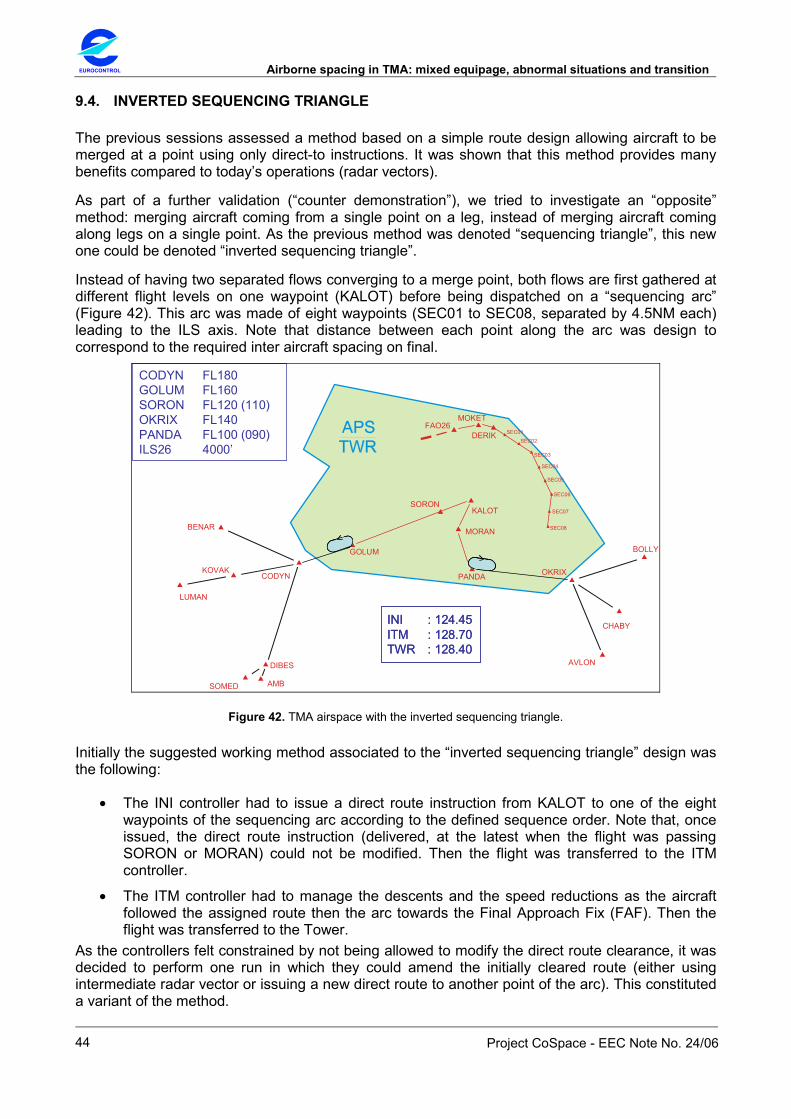
EUROCONTROL Airborne spacing in TMA: mixed equipage, abnormal situations and transition
Project CoSpace - EEC Note No. 24/06
44
9.4. INVERTED SEQUENCING TRIANGLE
The previous sessions assessed a method based on a simple route design allowing aircraft to be merged at a point using only direct-to instructions. It was shown that this method provides many benefits compared to today’s operations (radar vectors).
As part of a further validation (“counter demonstration”), we tried to investigate an “opposite” method: merging aircraft coming from a single point on a leg, instead of merging aircraft coming along legs on a single point. As the previous method was denoted “sequencing triangle”, this new one could be denoted “inverted sequencing triangle”.
Instead of having two separated flows converging to a merge point, both flows are first gathered at different flight levels on one waypoint (KALOT) before being dispatched on a “sequencing arc” (Figure 42). This arc was made of eight waypoints (SEC01 to SEC08, separated by 4.5NM each) leading to the ILS axis. Note that distance between each point along the arc was design to correspond to the required inter aircraft spacing on final.
AMB
AVLON
BENAR
MOKET
BOLLY
CODYN
CHABY
DIBES
KOVAK
LUMAN
OKRIX
SOMED
FAO26
GOLUM
DERIK
PANDA
MORAN
KALOT
SEC08
SEC07
SEC06
SEC05
SEC04
SEC03
SEC02SEC01
SORON
CODYN FL180GOLUM FL160SORON FL120 (110)OKRIX FL140PANDA FL100 (090)ILS26 4000’
INI : 124.45 ITM : 128.70TWR : 128.40
INI : 124.45 ITM : 128.70TWR : 128.40
Figure 42. TMA airspace with the inverted sequencing triangle.
Initially the suggested working method associated to the “inverted sequencing triangle” design was the following:
• The INI controller had to issue a direct route instruction from KALOT to one of the eight waypoints of the sequencing arc according to the defined sequence order. Note that, once issued, the direct route instruction (delivered, at the latest when the flight was passing SORON or MORAN) could not be modified. Then the flight was transferred to the ITM controller.
• The ITM controller had to manage the descents and the speed reductions as the aircraft followed the assigned route then the arc towards the Final Approach Fix (FAF). Then the flight was transferred to the Tower.
As the controllers felt constrained by not being allowed to modify the direct route clearance, it was decided to perform one run in which they could amend the initially cleared route (either using intermediate radar vector or issuing a new direct route to another point of the arc). This constituted a variant of the method.
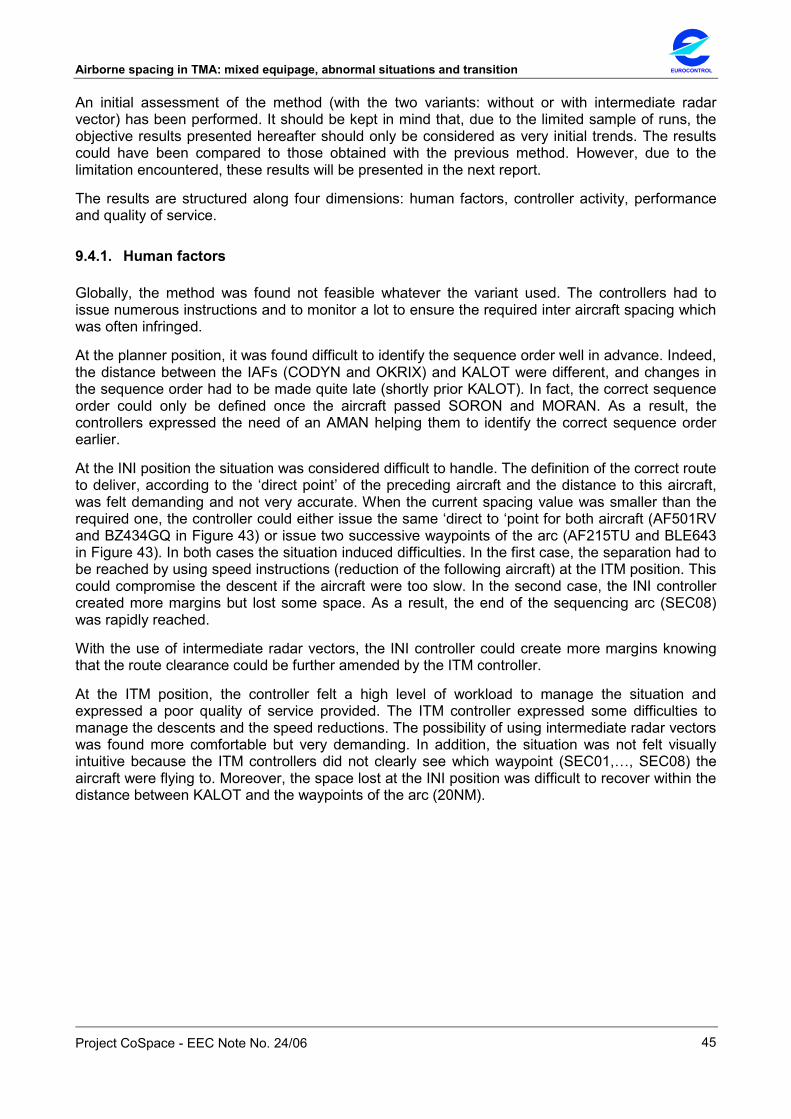
Airborne spacing in TMA: mixed equipage, abnormal situations and transition EUROCONTROL
Project CoSpace - EEC Note No. 24/06
45
An initial assessment of the method (with the two variants: without or with intermediate radar vector) has been performed. It should be kept in mind that, due to the limited sample of runs, the objective results presented hereafter should only be considered as very initial trends. The results could have been compared to those obtained with the previous method. However, due to the limitation encountered, these results will be presented in the next report.
The results are structured along four dimensions: human factors, controller activity, performance and quality of service.
9.4.1. Human factors
Globally, the method was found not feasible whatever the variant used. The controllers had to issue numerous instructions and to monitor a lot to ensure the required inter aircraft spacing which was often infringed.
At the planner position, it was found difficult to identify the sequence order well in advance. Indeed, the distance between the IAFs (CODYN and OKRIX) and KALOT were different, and changes in the sequence order had to be made quite late (shortly prior KALOT). In fact, the correct sequence order could only be defined once the aircraft passed SORON and MORAN. As a result, the controllers expressed the need of an AMAN helping them to identify the correct sequence order earlier.
At the INI position the situation was considered difficult to handle. The definition of the correct route to deliver, according to the ‘direct point’ of the preceding aircraft and the distance to this aircraft, was felt demanding and not very accurate. When the current spacing value was smaller than the required one, the controller could either issue the same ‘direct to ‘point for both aircraft (AF501RV and BZ434GQ in Figure 43) or issue two successive waypoints of the arc (AF215TU and BLE643 in Figure 43). In both cases the situation induced difficulties. In the first case, the separation had to be reached by using speed instructions (reduction of the following aircraft) at the ITM position. This could compromise the descent if the aircraft were too slow. In the second case, the INI controller created more margins but lost some space. As a result, the end of the sequencing arc (SEC08) was rapidly reached.
With the use of intermediate radar vectors, the INI controller could create more margins knowing that the route clearance could be further amended by the ITM controller.
At the ITM position, the controller felt a high level of workload to manage the situation and expressed a poor quality of service provided. The ITM controller expressed some difficulties to manage the descents and the speed reductions. The possibility of using intermediate radar vectors was found more comfortable but very demanding. In addition, the situation was not felt visually intuitive because the ITM controllers did not clearly see which waypoint (SEC01,…, SEC08) the aircraft were flying to. Moreover, the space lost at the INI position was difficult to recover within the distance between KALOT and the waypoints of the arc (20NM).
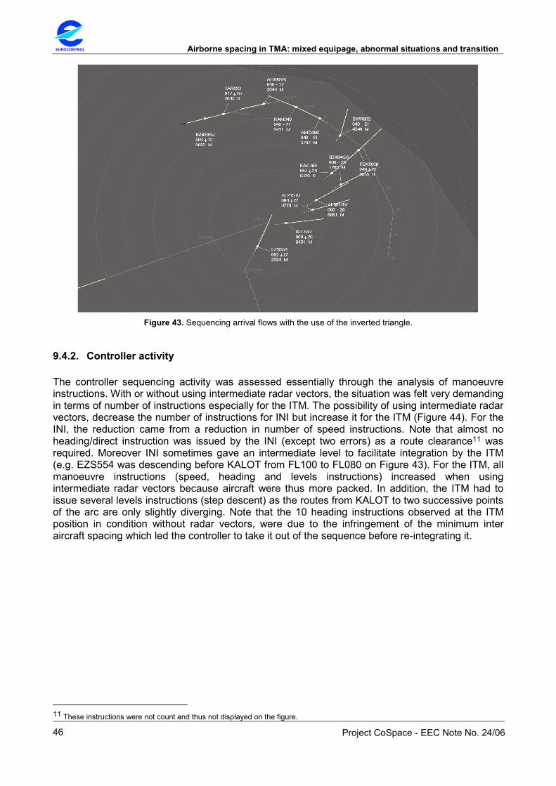
EUROCONTROL Airborne spacing in TMA: mixed equipage, abnormal situations and transition
Project CoSpace - EEC Note No. 24/06
46
Figure 43. Sequencing arrival flows with the use of the inverted triangle.
9.4.2. Controller activity
The controller sequencing activity was assessed essentially through the analysis of manoeuvre instructions. With or without using intermediate radar vectors, the situation was felt very demanding in terms of number of instructions especially for the ITM. The possibility of using intermediate radar vectors, decrease the number of instructions for INI but increase it for the ITM (Figure 44). For the INI, the reduction came from a reduction in number of speed instructions. Note that almost no heading/direct instruction was issued by the INI (except two errors) as a route clearance11 was required. Moreover INI sometimes gave an intermediate level to facilitate integration by the ITM (e.g. EZS554 was descending before KALOT from FL100 to FL080 on Figure 43). For the ITM, all manoeuvre instructions (speed, heading and levels instructions) increased when using intermediate radar vectors because aircraft were thus more packed. In addition, the ITM had to issue several levels instructions (step descent) as the routes from KALOT to two successive points of the arc are only slightly diverging. Note that the 10 heading instructions observed at the ITM position in condition without radar vectors, were due to the infringement of the minimum inter aircraft spacing which led the controller to take it out of the sequence before re-integrating it.
11 These instructions were not count and thus not displayed on the figure.
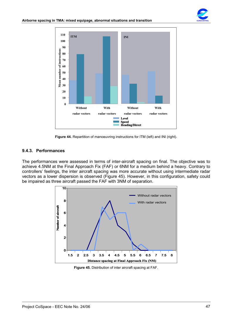
Airborne spacing in TMA: mixed equipage, abnormal situations and transition EUROCONTROL
Project CoSpace - EEC Note No. 24/06
47
INI
Without
radar vectors
With
radar vectors
0
Mea
nnu
mbe
rof
inst
ruct
ions
10
20
30
40
50
60
70
80
90
100
110 ITM
LevelLevelSpeedSpeedHeading/DirectHeading/Direct
Without
radar vectors
With
radar vectors
Figure 44. Repartition of manoeuvring instructions for ITM (left) and INI (right).
9.4.3. Performances
The performances were assessed in terms of inter-aircraft spacing on final. The objective was to achieve 4.5NM at the Final Approach Fix (FAF) or 6NM for a medium behind a heavy. Contrary to controllers’ feelings, the inter aircraft spacing was more accurate without using intermediate radar vectors as a lower dispersion is observed (Figure 45). However, in this configuration, safety could be impaired as three aircraft passed the FAF with 3NM of separation.
Distance spacing at Final Approach Fix (NM)
Num
ber
ofai
rcra
ft
0
2
4
6
8
10
1.5 2 2.5 3 3.5 4 4.5 5 5.5 6 6.5 7 7.5 8
Without radar vectors
With radar vectors
Distance spacing at Final Approach Fix (NM)
Num
ber
ofai
rcra
ft
0
2
4
6
8
10
1.5 2 2.5 3 3.5 4 4.5 5 5.5 6 6.5 7 7.5 80
2
4
6
8
10
1.5 2 2.5 3 3.5 4 4.5 5 5.5 6 6.5 7 7.5 8
Without radar vectors
With radar vectors
Figure 45. Distribution of inter aircraft spacing at FAF.
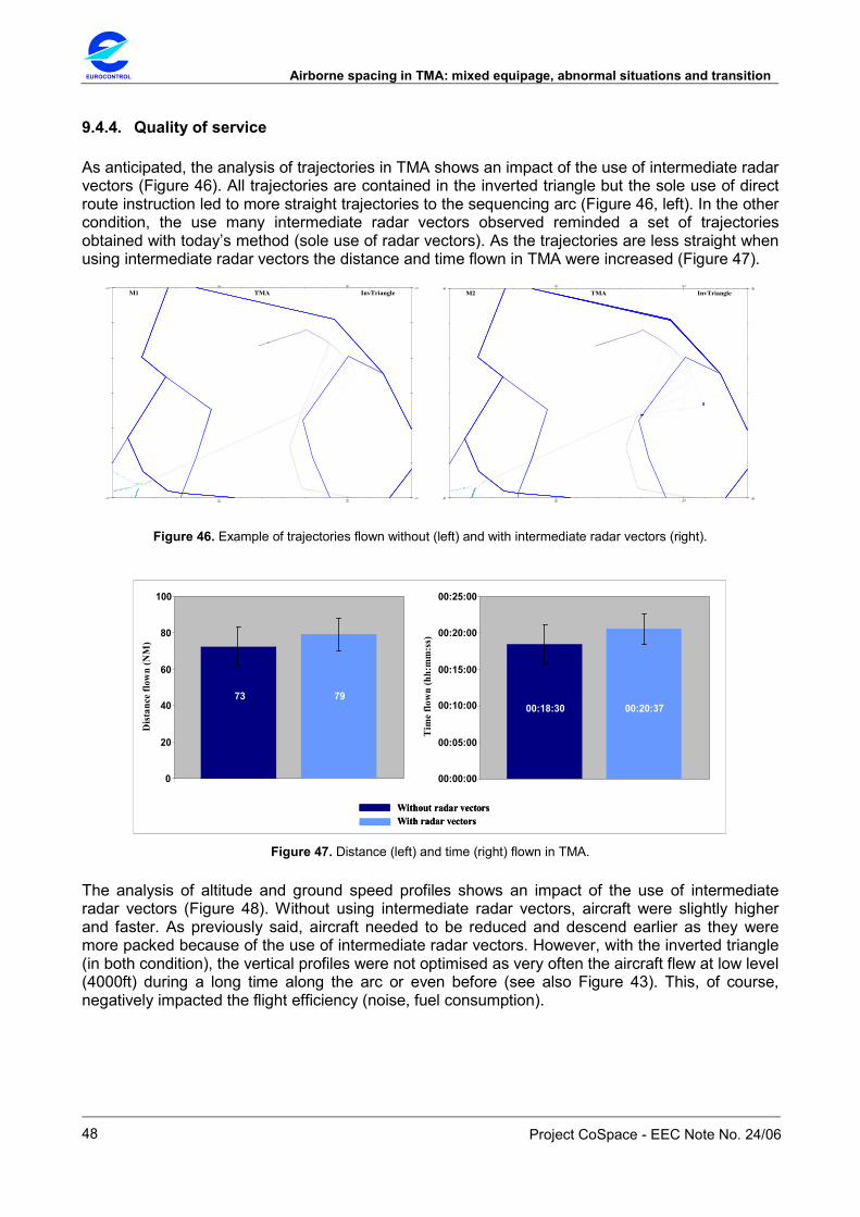
EUROCONTROL Airborne spacing in TMA: mixed equipage, abnormal situations and transition
Project CoSpace - EEC Note No. 24/06
48
9.4.4. Quality of service
As anticipated, the analysis of trajectories in TMA shows an impact of the use of intermediate radar vectors (Figure 46). All trajectories are contained in the inverted triangle but the sole use of direct route instruction led to more straight trajectories to the sequencing arc (Figure 46, left). In the other condition, the use many intermediate radar vectors observed reminded a set of trajectories obtained with today’s method (sole use of radar vectors). As the trajectories are less straight when using intermediate radar vectors the distance and time flown in TMA were increased (Figure 47).
InvTriangleM1 TMA
InvTriangleM2 TMA
Figure 46. Example of trajectories flown without (left) and with intermediate radar vectors (right).
00:18:30 00:20:37
00:00:00
00:05:00
00:10:00
00:15:00
00:20:00
00:25:00
Tim
eflo
wn
(hh:
mm
:ss)
73 79
0
20
40
60
80
100
Dis
tanc
e flo
wn
(NM
)
Without radar vectorsWithout radar vectorsWith radar vectorsWith radar vectors
Figure 47. Distance (left) and time (right) flown in TMA.
The analysis of altitude and ground speed profiles shows an impact of the use of intermediate radar vectors (Figure 48). Without using intermediate radar vectors, aircraft were slightly higher and faster. As previously said, aircraft needed to be reduced and descend earlier as they were more packed because of the use of intermediate radar vectors. However, with the inverted triangle (in both condition), the vertical profiles were not optimised as very often the aircraft flew at low level (4000ft) during a long time along the arc or even before (see also Figure 43). This, of course, negatively impacted the flight efficiency (noise, fuel consumption).

Airborne spacing in TMA: mixed equipage, abnormal situations and transition EUROCONTROL
Project CoSpace - EEC Note No. 24/06
49
150
175
200
225
250
275
300
0 5 10 15 20 25 30 35 40 45 50 55 60 65
Spee
d in
kt
150
175
200
225
250
275
300
0 5 10 15 20 25 30 35 40 45 50 55 60 65
Spee
d in
kt
Distance to Final Approach Fix (NM)
0
20
40
60
80
100
120
140
0 5 10 15 20 25 30 35 40 45 50 55 60 65
Alti
tude
in fe
et(*
100)
MeanStd dev
MeanStd dev
Without radar vectors
With radar vectorsMeanStd dev
MeanStd dev
Without radar vectors
With radar vectors
Distance to Final Approach Fix (NM) Figure 48. Altitude (left) and ground speed profiles (right).
9.4.5. Safety
The tight margins for manoeuvre and the high level of workload sometimes resulted in the infringement of the minimum inter aircraft spacing. These situations were handled by following the procedures set during previous sessions: isolating the aircraft (i.e. take it out of the sequence) before re-integrating it when appropriate (Figure 49). The possibility of using intermediate radar vectors was considered safer, but less than today’s method.
Figure 49. Infringement of the spacing. The aircraft TCV840 had to be taken
out of the sequence as it was too close to the preceding one.
EUROCONTROL Airborne spacing in TMA: mixed equipage, abnormal situations and transition
Project CoSpace - EEC Note No. 24/06
50
In addition, all controllers expressed the feeling of being “trapped” because they knew very late (once aircraft passed KALOT) that all the traffic could be contained on the arc. If the TMA became overloaded, this could not be solved by opening the holding patterns as they were located upstream KALOT (at GOLUM and PANDA). However, this could be solved with the help of an AMAN.
9.5. SUMMARY
The method (“sequencing triangle”) was improved with the new type of legs approximating circles. When creating the sequencing, the direct-to could be given more accurately, which should facilitate the maintaining (further refinement) of the sequence. The higher altitudes on the legs allowed a better descent and climb profiles. However, with the speed reductions imposed due to the high traffic load, the altitudes were found on some occasions too high. Aircraft had to be descended while on the legs, which induced more workload and negatively impacted the task sharing. A minor adaptation of the route structure is required.
In contrast, the “opposite” method tested (“inverted sequencing triangle”) was not found feasible. It raised many problems in terms of workload, communication, descent profiles, quality of service provided and safety. In real busy situations, the method may generate go-around and incidents. No benefits were reported. This initial investigation may suggest abandoning the “opposite” method.

Airborne spacing in TMA: mixed equipage, abnormal situations and transition EUROCONTROL
Project CoSpace - EEC Note No. 24/06
51
10. SESSION VIII
10.1. OBJECTIVE
The previous session showed that the method was improved with the new type of legs approximating circles. When creating the sequencing, the direct-to could be given more accurately, thus facilitating the maintaining (further refinement) of the sequence. In addition, the higher altitudes on the legs allowed a better descent and climb profiles. However, with the speed reductions imposed due to the high traffic load, the altitudes were found on some occasions too high.
The objective of the present session was twofold:
• To perform an initial quantitative assessment of the method with minor adaptations of the route structure to facilitate the descent.
• To investigate the feasibility, benefits and limits of delivering in advance the complete route instead of issuing immediate direct-to instruction. For that purpose, additional points were defined on each leg.
The main aspects considered were: human factors, controller activity, performances, quality of service and safety. It should be reminded that, due to the limited sample of runs, the results presented hereafter should only be considered as very initial trends.
10.2. ORGANISATION AND SETUP
The session took place during two days (12 and 15 June 2006) and involved three controllers who participated in the previous sessions. A preparation phase was conducted with two controllers to define the modified route structure and the traffic samples. The two conditions were: use of the curved sequencing triangle (denoted “Curved segments”) versus use of intermediate points along the legs (denoted “Curved points”). The session consisted of six runs: two runs in condition “Curved segments” and four runs in condition “Curved points” (including two training runs as this condition was never tested before).
The simulated airspace was derived from the one used during the previous sessions and consisted of a TMA sector. In condition “Curved segments”, the TMA had two parallel (2000ft separated) and curved sequencing legs made of three segments (PYPOL- SEC06 and POLUX – SEC03) concentric a merge point (LOTAK) as shown in Figure 50 left. In this condition, the controller could issue a direct-to anywhere along the leg. In condition “Curved points”, additional points (SEC01 to SEC15) were added on each leg as shown in Figure 50, right. The distance between two consecutive points (4.5NM) corresponds to the required spacing on final approach (between aircraft of same type). In this condition, controllers were asked to deliver the route towards the merge point using one of these points – direct-to instructions should not be used. The flight level constraints were identical in both conditions and remained the same as those used in the previous session (i.e. FL120 at PIPOL and FL100 at POLUX).
New traffic samples were used retaining 40 arrivals per hour (including 20% of “heavy” aircraft). A complete phraseology (announcement of ILS, indication of QNH value) was used. For both conditions, the TMA had two positions (frequencies): initial (pick-up) and intermediate (feeder) with one executive controller on each position. The third controller was acting as a planner. The analysis period was 45 minutes from the first aircraft reaching the Final Approach Fix (FAF).

EUROCONTROL Airborne spacing in TMA: mixed equipage, abnormal situations and transition
Project CoSpace - EEC Note No. 24/06
52
TMA (Curved segment)
AMB
AVLON
BENAR
MOKET
BOLLY
CODYN
CHABY
DIBES
KOVAK
LOTAK
LUMANOKRIX
SOMED
FAO26
PYPOL
POLUX
VASOL
ODRANARCOS
SEC03
KIRED
SEC06
SEC02
SEC01SEC04
SEC05
VASOL FL140PYPOL FL120 (110)ARCOS FL120POLUX FL100 (090)ILS 26 4000’
TMA (Curved points)
VASOL FL140PYPOL FL120 (110)ARCOS FL120POLUX FL100 (090)ILS 26 4000’
AMB
BENAR
MOKET
BOLLY
CODYN
CHABY
KOVAK
LOTAK
LUMANOKRIX
SOMED
FAO26
PYPOL
POLUX
ARCOS
SEC03
KIRED
SEC02 SEC01
SEC04
SEC05
SEC10
SEC11
SEC12SEC13
SEC14 SEC15
SEC06
AVLONDIBES
ODRAN
VASOL
Figure 50. TMA airspace for “Curved segments” (left) and “Curved points” (right) conditions.
10.3. HUMAN FACTORS
The initial feedback obtained during the previous session was confirmed: in both conditions, the method was improved with the new type of legs and was found very useful and efficient to handle a high level of traffic. The adaptation of the routes (moved back 3NM) increased the manoeuvre margin and facilitated the descent. This allowed implementing the efficient task allocation previously defined. The method with “curved points” remained feasible but led to an increase of workload, and a loss of flexibility and accuracy for both positions (INI and ITM).
The method had no impact on the definition of the sequence order for the planning controller. However, as in the previous session, identifying the sequence order well in advance was found slightly more difficult compared to route structure with straight parallel legs. This was caused by the non-straight route ODRAN-VASOL-PYPOL, Consequently, the PLC could efficiently define the sequence order only once the aircraft passed VASOL and ARCOS.
In curved points condition, at the INI position, controllers felt constrained as they could only turn the aircraft at the intermediate points. They had either to take more space or to pack the aircraft (Figure 51). In the first case, the INI controller had to wait that the following aircraft reached an intermediate point to turn it, which wasted some space. In addition, with heavy traffic the aircraft went farther along the legs, sometimes reaching the last points (SEC06 or SEC15). For ITM, this implied maintaining higher speed to regain the required spacing. In the other case, some space was gained by turning at the same intermediate point two aircraft not totally spaced by 4.5NM. However, the ITM controller had to regain the required spacing by imposing a low speed, which sometimes led to difficulties during the descent towards the ILS particularly with heavy traffic. Both cases led to an increase of workload for the ITM. As a result, in curved points condition, the objective of each controller (INI and ITM) appears to be slightly conflicting: the INI had to reduce speed of aircraft to handle the traffic without overshooting the legs whereas the ITM needed enough speed margin to recover the spacing not achieved with enough accuracy by INI.
In terms of anticipation, the controllers agreed that it was limited: the decision on when turning the aircraft was generally made at the preceding point. In effect, the controller knew the appropriate point to turn an aircraft once the preceding one had just turned12. However, anticipation could be increased with an enhanced AMAN indicating the turning point.
12 This is similar to the use of ASAS instructions in which the controller issues the ‘heading then merge’ once the preceding aircraft reported the ‘merge’, i.e. when it turns to the merge point.

Airborne spacing in TMA: mixed equipage, abnormal situations and transition EUROCONTROL
Project CoSpace - EEC Note No. 24/06
53
Figure 51. Loss of accuracy at INI position: taking extra space (right) or packing the aircraft (left).
10.4. CONTROLLER ACTIVITY
The controller sequencing activity was assessed essentially through the analysis of manoeuvre instructions. It should be noted that, whereas every speed, level or heading/direct instructions were recorded, the delivery of the route (curved points condition) was not recorded. The number of routes clearance shall normally correspond exactly to that of direct instructions. No significant impact of the condition was observed when considering average values of speed and level instructions (Figure 52). In curved segments condition, the INI issued one speed, one levels and one direct-to instructions per aircraft, then the ITM issued one level instruction and refined the sequence with typically 2 speed instructions per aircraft. In curved points condition, more speed instructions could have been anticipated at ITM to regain the lack of accuracy induced at INI. The higher dispersion observed (speed instructions in curved points condition for ITM, or speed instructions for curved segments for INI) may not be relevant (only two runs).
Curved segments0
INI
Mea
nnu
mbe
rof
inst
ruct
ions
10
20
30
40
50
60
70
80
90
100
110
Curved points
ITM
Curved segments Curved points
LevelSpeedHeading/Direct
Curved segments0
INI
Mea
nnu
mbe
rof
inst
ruct
ions
10
20
30
40
50
60
70
80
90
100
110
Curved points
ITM
Curved segments Curved points
LevelSpeedHeading/Direct
LevelLevelSpeedSpeedHeading/DirectHeading/Direct
Figure 52. Repartition of manoeuvring instructions for ITM (left) and INI (right).
Delivery of route is not displayed (INI, curved points condition).

EUROCONTROL Airborne spacing in TMA: mixed equipage, abnormal situations and transition
Project CoSpace - EEC Note No. 24/06
54
10.5. PERFORMANCES
The performances were assessed in terms of inter-aircraft spacing. The objective was to achieve 4.5NM on final between aircraft at 180kt (or 6NM for a medium behind a heavy). As opposed to the feeling of controllers, on average, the inter aircraft spacing was closer to the required value in curved points condition (Figure 53, left). The controllers packed more the aircraft in curved segments condition as they would do in real situation (Figure 53, right). A higher dispersion could have been anticipated with in curved points condition due to the lack of accuracy at INI position.
0
2
4
6
8
10
1.5 2 2.5 3 3.5 4 4.5 5 5.5 6 6.5 7 7.5 8
Distance spacing at Final Approach Fix (NM)
Num
ber
ofai
rcra
ft
Curved segments
Curved points
0
2
4
6
8
10
1.5 2 2.5 3 3.5 4 4.5 5 5.5 6 6.5 7 7.5 8
Distance spacing at Final Approach Fix (NM)
Num
ber
ofai
rcra
ft
Curved segments
Curved points
Curved pointsCurved segments
Mea
nsp
acin
gva
lue
(NM
)
2
3
4
5
6
7
Min for 95%
Max for 95%
Mean-STD
Mean+STDMean
Max
Min
Curved pointsCurved segments
Mea
nsp
acin
gva
lue
(NM
)
2
3
4
5
6
7
Min for 95%
Max for 95%
Mean-STD
Mean+STDMean
Max
Min
Mea
nsp
acin
gva
lue
(NM
)
2
3
4
5
6
7
Min for 95%
Max for 95%
Mean-STD
Mean+STDMean
Max
MinMin for 95%
Max for 95%
Mean-STD
Mean+STDMean
Max
Min
Figure 53. Inter-aircraft spacing at final approach fix, overall mean (left) and distribution of mean (right).
10.6. QUALITY OF SERVICE
As anticipated, the analysis of trajectories shows an impact of the condition (Figure 54). It can be seen that, in curved segment condition, the aircraft turned at any time along the leg, whereas in curved points condition, the aircraft only turned at intermediate point. The dispersion is contained within a pre-defined triangle located upstream of the ILS. Distance and time flown were similar in both conditions: aircraft flew 70NM during 17 minutes on average (Figure 55).
CurvedPM1 TMACurvedSM2 TMA
Figure 54. Example of trajectories flown in curved segments (left) and in curved points (right) conditions.

Airborne spacing in TMA: mixed equipage, abnormal situations and transition EUROCONTROL
Project CoSpace - EEC Note No. 24/06
55
00:00:00
00:05:00
00:10:00
00:15:00
00:20:00
Mea
nT
ime
(hh:
mm
:ss)
00:00:00
00:05:00
00:10:00
00:15:00
00:20:00
Mea
nT
ime
(hh:
mm
:ss)
CurvedsegmentsCurvedsegments CurvedpointsCurvedpoints
Mea
nD
ista
nce
(NM
)
0
20
40
60
80
100
Mea
nD
ista
nce
(NM
)
0
20
40
60
80
100
0
20
40
60
80
100
Figure 55. Distance (left) and time (right) flown.
The analysis of altitude and ground speed profiles shows no impact of the condition (Figure 56). In both conditions, the aircraft followed the same speed and altitude profile in performing almost a continuous descent once leaving the legs (from 40NM to the FAF at FL120 or FL100) until the ILS at 4000ft. This is due to the higher altitudes of the legs and the increased availability and manoeuvre margin at the ITM position allowing to better arrange descent and speed.
MeanStd dev
MeanStd dev
Curved segments
Curved points
Distance to Final Approach Fix (NM)
0
20
40
60
80
100
120
140
0 5 10 15 20 25 30 35 40 45 50 55 60 65
Distance to Final Approach Fix (NM)
Spee
d in
kt
140
160
180
200
220
240
260
280
300
0 5 10 15 20 25 30 35 40 45 50 55 60 65
Alti
tude
in fe
et(*
100)
MeanStd dev
MeanStd dev
Curved segments
Curved pointsMeanStd dev
MeanStd dev
Curved segments
Curved points
Distance to Final Approach Fix (NM)
0
20
40
60
80
100
120
140
0 5 10 15 20 25 30 35 40 45 50 55 60 650
20
40
60
80
100
120
140
0 5 10 15 20 25 30 35 40 45 50 55 60 650 5 10 15 20 25 30 35 40 45 50 55 60 65
Distance to Final Approach Fix (NM)
Spee
d in
kt
140
160
180
200
220
240
260
280
300
0 5 10 15 20 25 30 35 40 45 50 55 60 65140
160
180
200
220
240
260
280
300
0 5 10 15 20 25 30 35 40 45 50 55 60 650 5 10 15 20 25 30 35 40 45 50 55 60 65
Alti
tude
in fe
et(*
100)
Figure 56. Altitude (left) and ground speed (right) profiles.
10.7. SAFETY
Safety benefits provided by the method were still here (reduction of communication and workload, increase monitoring, more orderly flows of traffic) but no impact of the condition was reported.
10.8. SUMMARY
The session confirmed that the use of curved segments improves the method, which was found effective for handling a high traffic load. The adaptations of the route structure facilitated the descent and would allow continuous descent once leaving the legs (FL100 or FL120) to ILS. With the use of intermediate points to deliver the route, the method was found feasible but less flexible, less accurate and inducing more workload. Assistance (in the form of an enhanced arrival manager) would be needed to identify the route in advance. The trends obtained were consistent with previous sessions and showed in particular better descent profiles. No impact on the condition could be observed whereas more speed instructions and/or less accuracy on final could have been anticipated. Further data collection would be needed to confirm the trends.
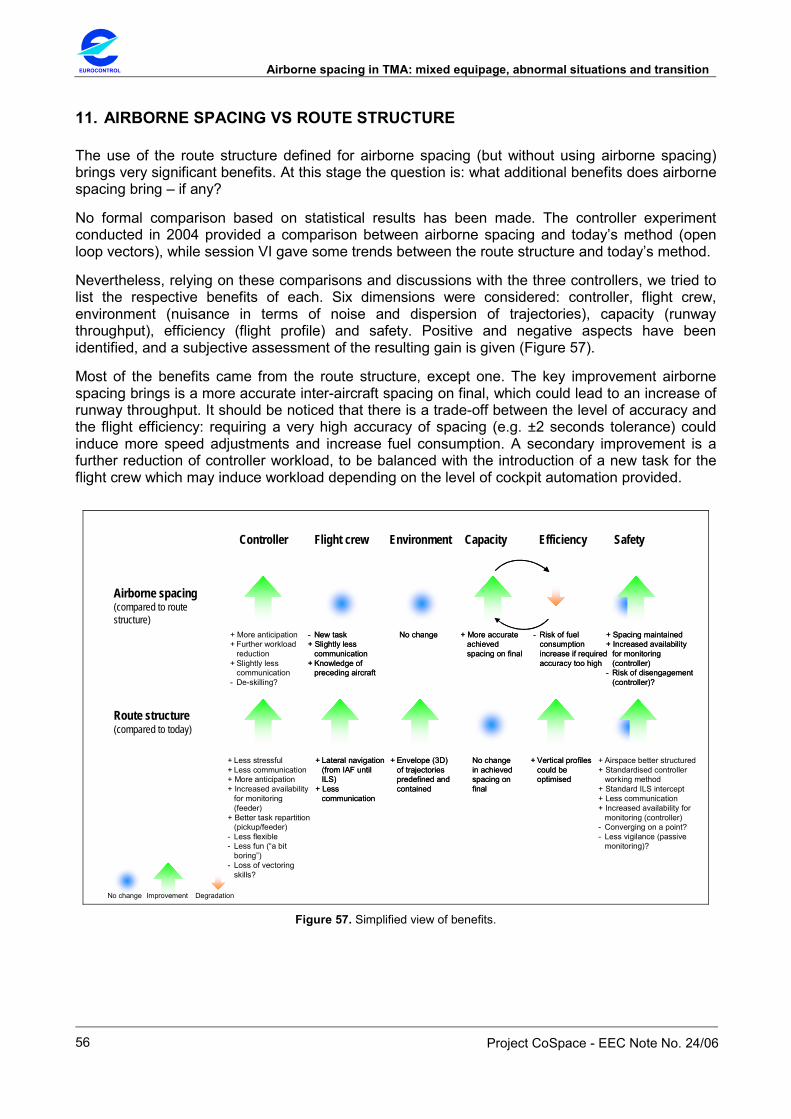
EUROCONTROL Airborne spacing in TMA: mixed equipage, abnormal situations and transition
Project CoSpace - EEC Note No. 24/06
56
11. AIRBORNE SPACING VS ROUTE STRUCTURE
The use of the route structure defined for airborne spacing (but without using airborne spacing) brings very significant benefits. At this stage the question is: what additional benefits does airborne spacing bring – if any?
No formal comparison based on statistical results has been made. The controller experiment conducted in 2004 provided a comparison between airborne spacing and today’s method (open loop vectors), while session VI gave some trends between the route structure and today’s method.
Nevertheless, relying on these comparisons and discussions with the three controllers, we tried to list the respective benefits of each. Six dimensions were considered: controller, flight crew, environment (nuisance in terms of noise and dispersion of trajectories), capacity (runway throughput), efficiency (flight profile) and safety. Positive and negative aspects have been identified, and a subjective assessment of the resulting gain is given (Figure 57).
Most of the benefits came from the route structure, except one. The key improvement airborne spacing brings is a more accurate inter-aircraft spacing on final, which could lead to an increase of runway throughput. It should be noticed that there is a trade-off between the level of accuracy and the flight efficiency: requiring a very high accuracy of spacing (e.g. ±2 seconds tolerance) could induce more speed adjustments and increase fuel consumption. A secondary improvement is a further reduction of controller workload, to be balanced with the introduction of a new task for the flight crew which may induce workload depending on the level of cockpit automation provided.
Controller Flight crew Environment Capacity Efficiency Safety
Airborne spacing(compared to route structure)
Route structure(compared to today)
+ More anticipation+ Further workload
reduction+ Slightly less
communication- De-skilling?
- New task+ Slightly less
communication+ Knowledge of
preceding aircraft
- New task+ Slightly less
communication+ Knowledge of
preceding aircraft
No changeNo change + More accurate achieved spacing on final
- Risk of fuel consumption increase if required accuracy too high
+ More accurate achieved spacing on final
- Risk of fuel consumption increase if required accuracy too high
+ Spacing maintained+ Increased availability
for monitoring (controller)
- Risk of disengagement (controller)?
+ Spacing maintained+ Increased availability
for monitoring (controller)
- Risk of disengagement (controller)?
+ Lateral navigation (from IAF until ILS)
+ Less communication
+ Lateral navigation (from IAF until ILS)
+ Less communication
+ Envelope (3D) of trajectories predefined and contained
+ Envelope (3D) of trajectories predefined and contained
No change in achieved spacing on final
No change in achieved spacing on final
+ Vertical profiles could be optimised
+ Vertical profiles could be optimised
+ Less stressful+ Less communication+ More anticipation+ Increased availability
for monitoring (feeder)
+ Better task repartition (pickup/feeder)
- Less flexible- Less fun (“a bit
boring”)- Loss of vectoring
skills?
+ Airspace better structured+ Standardised controller
working method+ Standard ILS intercept+ Less communication+ Increased availability for
monitoring (controller)- Converging on a point?- Less vigilance (passive
monitoring)?
No change Improvement Degradation Figure 57. Simplified view of benefits.

Airborne spacing in TMA: mixed equipage, abnormal situations and transition EUROCONTROL
Project CoSpace - EEC Note No. 24/06
57
12. CONCLUSIONS
A series of small-scale controller experiments was conducted to investigate (1) the handling of non-nominal situations when using airborne spacing in the terminal area; (2) the benefits of the sole use of the route structure defined for airborne spacing in the terminal area with no airborne spacing equipped aircraft.
The following non nominal situations were considered: mixed equipage, holding patterns and typical unexpected events (go-around, emergency, radio failure, spacing instructions not correctly executed). In applying the airborne spacing procedure for non equipped aircraft, handling mixed equipage was found to be entirely feasible. Initial trends suggest that 50% equipped aircraft already brings some benefits compared to 0% although not as much as with 100%. Receiving aircraft from the holding patterns and then using airborne spacing for final integration was found feasible and comfortable. Recovering from the unexpected events was found less difficult than initially anticipated and was evaluated as similar to today’s operations.
The use of the route structure (without airborne spacing) was found comfortable, safe and accurate, even under high traffic load, although less flexible than today. Predictability was increased, workload and communications were reduced. Open loop radar vectors were no longer used and aircraft remained on lateral navigation mode. The inter-aircraft spacing on final was as accurate as today, while descent profiles were improved. The flow of traffic was more orderly with a contained and predefined dispersion of trajectories. All these elements should contribute to improve safety. Furthermore, the method offers the potential for continuous descent from FL100 until final approach fix. No specific airborne functions or ground tools are required, other than area navigation (RNAV) capabilities.
The key improvement airborne spacing brings compared to the route structure is a more accurate inter-aircraft spacing on final, which could lead to an increase of runway throughput. A secondary improvement is a further reduction of controller workload, to be balanced with the introduction of a new task for the flight crew.
The use of the route structure could be seen from different perspectives: as a goal in itself since it provides benefits; as a preliminary step to prepare the implementation of airborne spacing; as a transition towards the systematic use of area navigation; and eventually as a sound foundation to support further improvements (e.g. continuous descent) and new concepts (e.g. target time of arrival).