ETSI EN 302 065-1 V2.1 302 065... · Users of the present document should be aware that the...
48
ETSI EN 302 065-1 V2.1.1 (2016-11) Electromagnetic compatibility and Radio spectrum Matters (ERM); Short Range Devices (SRD) using Ultra Wide Band technology (UWB); Harmonized EN Harmonised Standard covering the essential requirements of article 3.2 of the R&TTE Directive; 2014/53/EU; Part 1: Requirements for Generic UWB applications HARMONISED EUROPEAN STANDARD
Transcript of ETSI EN 302 065-1 V2.1 302 065... · Users of the present document should be aware that the...
ETSI EN 302 065-1 V2.1.1 (2016-11)
Electromagnetic compatibility and Radio spectrum Matters (ERM); Short Range Devices (SRD) using
Ultra Wide Band technology (UWB);
Harmonized EN Harmonised Standard covering the essential requirements
of article 3.2 of the R&TTE Directive; 2014/53/EU;
Part 1: Requirements for Generic UWB applications
HARMONISED EUROPEAN STANDARD

ETSI
ETSI EN 302 065-1 V2.1.1 (2016-11) 2
Reference
REN/ERM-TGUWB-128
Keywords
harmonised standard, radio, regulation, SRD, testing, UWB
ETSI
650 Route des Lucioles F-06921 Sophia Antipolis Cedex - FRANCE
Tel.: +33 4 92 94 42 00 Fax: +33 4 93 65 47 16
Siret N° 348 623 562 00017 - NAF 742 C
Association à but non lucratif enregistrée à la Sous-Préfecture de Grasse (06) N° 7803/88
Important notice
The present document can be downloaded from: http://www.etsi.org/standards-search
The present document may be made available in electronic versions and/or in print. The content of any electronic and/or print versions of the present document shall not be modified without the prior written authorization of ETSI. In case of any
existing or perceived difference in contents between such versions and/or in print, the only prevailing document is the print of the Portable Document Format (PDF) version kept on a specific network drive within ETSI Secretariat.
Users of the present document should be aware that the document may be subject to revision or change of status. Information on the current status of this and other ETSI documents is available at
https://portal.etsi.org/TB/ETSIDeliverableStatus.aspx
If you find errors in the present document, please send your comment to one of the following services: https://portal.etsi.org/People/CommiteeSupportStaff.aspx
Copyright Notification
No part may be reproduced or utilized in any form or by any means, electronic or mechanical, including photocopying and microfilm except as authorized by written permission of ETSI.
The content of the PDF version shall not be modified without the written authorization of ETSI. The copyright and the foregoing restriction extend to reproduction in all media.
© European Telecommunications Standards Institute 2016.
All rights reserved.
DECTTM, PLUGTESTSTM, UMTSTM and the ETSI logo are Trade Marks of ETSI registered for the benefit of its Members. 3GPPTM and LTE™ are Trade Marks of ETSI registered for the benefit of its Members and
of the 3GPP Organizational Partners. GSM® and the GSM logo are Trade Marks registered and owned by the GSM Association.
ETSI
ETSI EN 302 065-1 V2.1.1 (2016-11) 3
Contents
Intellectual Property Rights ................................................................................................................................ 6
Foreword............................................................................................................................................................. 6
Modal verbs terminology ................................................................................................................................... 7
1 Scope ........................................................................................................................................................ 8
2 References ................................................................................................................................................ 9 2.1 Normative references ......................................................................................................................................... 9 2.2 Informative references ....................................................................................................................................... 9
3 Definitions, symbols and abbreviations ................................................................................................. 11 3.1 Definitions ....................................................................................................................................................... 11 3.2 Symbols ........................................................................................................................................................... 12 3.3 Abbreviations ................................................................................................................................................... 12
4 Technical requirements specifications ................................................................................................... 13 4.1 Environmental conditions ................................................................................................................................ 13 4.2 General ............................................................................................................................................................. 13 4.3 Transmitter Conformance Requirements ......................................................................................................... 14 4.3.1 Operating Bandwidth ................................................................................................................................. 14 4.3.1.1 Applicability ......................................................................................................................................... 14 4.3.1.2 Description ........................................................................................................................................... 14 4.3.1.3 Limits.................................................................................................................................................... 15 4.3.1.4 Conformance ........................................................................................................................................ 15 4.3.2 Maximum Value of Mean Power Spectral Density .................................................................................... 15 4.3.2.1 Applicability ......................................................................................................................................... 15 4.3.2.2 Description ........................................................................................................................................... 15 4.3.2.3 Limits.................................................................................................................................................... 15 4.3.2.4 Conformance ........................................................................................................................................ 16 4.3.3 Maximum value of peak power .................................................................................................................. 16 4.3.3.1 Applicability ......................................................................................................................................... 16 4.3.3.2 Description ........................................................................................................................................... 16 4.3.3.3 Limits.................................................................................................................................................... 17 4.3.3.4 Conformance ........................................................................................................................................ 17 4.3.4 Exterior Limits ........................................................................................................................................... 17 4.3.5 Total Power ................................................................................................................................................ 17 4.3.6 Other Emissions ......................................................................................................................................... 17 4.3.6.1 Applicability ......................................................................................................................................... 17 4.3.6.2 Description ........................................................................................................................................... 18 4.3.6.3 Limits.................................................................................................................................................... 18 4.3.6.4 Conformance ........................................................................................................................................ 18 4.3.7 Transmitter Unwanted Emissions .............................................................................................................. 18 4.4 Receiver Conformance Requirements ............................................................................................................. 18 4.4.1 General ....................................................................................................................................................... 18 4.4.2 Receiver spurious emissions ...................................................................................................................... 19 4.4.2.1 Applicability ......................................................................................................................................... 19 4.4.2.2 Description ........................................................................................................................................... 19 4.4.2.3 Limits.................................................................................................................................................... 19 4.4.2.4 Conformance ........................................................................................................................................ 19 4.4.3 Receiver interference handling ................................................................................................................... 19 4.4.3.1 Applicability ......................................................................................................................................... 19 4.4.3.2 Description ........................................................................................................................................... 20 4.4.3.3 Limits.................................................................................................................................................... 20 4.4.3.4 Conformance ........................................................................................................................................ 20 4.5 Requirements for Spectrum Access ................................................................................................................. 20 4.5.1 Detect and Avoid (DAA) ........................................................................................................................... 20 4.5.1.1 Applicability ......................................................................................................................................... 20 4.5.1.2 Description ........................................................................................................................................... 20
ETSI
ETSI EN 302 065-1 V2.1.1 (2016-11) 4
4.5.1.3 Limits.................................................................................................................................................... 20 4.5.1.4 Conformance ........................................................................................................................................ 21 4.5.2 Listen-Before-Talk (LBT) .......................................................................................................................... 21 4.5.3 Low Duty Cycle (LDC).............................................................................................................................. 21 4.5.3.1 Applicability ......................................................................................................................................... 21 4.5.3.2 Description ........................................................................................................................................... 21 4.5.3.3 Limits.................................................................................................................................................... 21 4.5.3.4 Conformance ........................................................................................................................................ 21 4.6 Antenna Requirements ..................................................................................................................................... 22 4.7 Other Requirements and Mitigation techniques ............................................................................................... 22
5 Testing for compliance with technical requirements.............................................................................. 22 5.1 Environmental conditions for testing ............................................................................................................... 22 5.2 General conditions for testing .......................................................................................................................... 23 5.2.1 Product information ................................................................................................................................... 23 5.2.2 Requirements for the test modulation......................................................................................................... 23 5.2.3 Test conditions, power supply and ambient temperatures .......................................................................... 23 5.2.4 Choice of equipment for test suites ............................................................................................................ 23 5.2.5 Multiple Operating bandwidths and multiband equipment ........................................................................ 23 5.2.6 Testing of host connected equipment and plug-in radio devices ................................................................ 23 5.3 Interpretation of the measurement results ........................................................................................................ 24 5.3.0 General ....................................................................................................................................................... 24 5.3.1 Measurement uncertainty is equal to or less than maximum acceptable uncertainty ................................. 24 5.3.2 Measurement uncertainty is greater than maximum acceptable uncertainty .............................................. 24 5.3.3 Emissions ................................................................................................................................................... 25
6 Conformance test suits ........................................................................................................................... 25 6.1 Introduction...................................................................................................................................................... 25 6.2 Initial Measurement steps ................................................................................................................................ 26 6.3 Radiated measurements ................................................................................................................................... 26 6.3.1 General ....................................................................................................................................................... 26 6.3.2 Test sites and general arrangements for measurements involving the use of radiated fields ..................... 26 6.3.3 Guidance on the use of a radiation test site ................................................................................................ 26 6.3.3.1 General ................................................................................................................................................. 26 6.3.3.2 Range length. ........................................................................................................................................ 26 6.3.4 Coupling of signals .................................................................................................................................... 27 6.3.5 Standard test methods................................................................................................................................. 27 6.3.5.1 Generic measurement method .............................................................................................................. 27 6.3.5.1.1 Calibrated setup .............................................................................................................................. 27 6.3.5.1.2 Substitution method ........................................................................................................................ 27 6.3.6 Standard calibration method ....................................................................................................................... 31 6.4 Conducted measurements ................................................................................................................................ 32 6.4.1 General Setup ............................................................................................................................................. 32 6.4.2 Specific Setup............................................................................................................................................. 32 6.5 Conformance methods of measurement for transmitter ................................................................................... 32 6.5.1 General ....................................................................................................................................................... 32 6.5.2 Method of measurements of the Ultra Wideband Emissions ..................................................................... 32 6.5.3 Operating Bandwidth ................................................................................................................................. 32 6.5.4 Mean power spectral density measurements .............................................................................................. 32 6.5.5 Peak power measurements ......................................................................................................................... 33 6.5.6 Exterior limit measurement ........................................................................................................................ 33 6.5.7 Total Power ................................................................................................................................................ 33 6.5.8 Transmitter unwanted emissions ................................................................................................................ 33 6.6 Conformance methods of measurement for receiver ....................................................................................... 33 6.6.1 Receiver spurious emissions ...................................................................................................................... 33 6.6.2 Receiver interference handling ................................................................................................................... 33 6.7 Conformance test suites for spectrum access ................................................................................................... 33 6.7.1 Detect and Avoid (DAA) ........................................................................................................................... 33 6.7.2 Listen Before Talk ...................................................................................................................................... 34 6.7.3 Low Duty Cycle ......................................................................................................................................... 34 6.7.4 Conformance test suites for antenna requirements ..................................................................................... 34 6.7.5 Other Test Suites ........................................................................................................................................ 34
ETSI
ETSI EN 302 065-1 V2.1.1 (2016-11) 5
Annex A (normative): Relationship between the present document and the essential
requirements of Directive 2014/53/EU ......................................................... 35
Annex B (informative): Application form for testing ......................................................................... 38
B.1 Introduction ............................................................................................................................................ 38
B.2 Product Information for ETSI EN 302 065-1, clause 5.2.1 .................................................................... 38 B.2.1 Type of Equipment (stand-alone, combined, plug-in radio device, etc.) ......................................................... 38 B.2.2 The nominal voltages of the stand-alone radio equipment or the nominal voltages of the combined
(host) equipment or test jig in case of plug-in devices ..................................................................................... 38
B.3 Signal related Information for ETSI EN 302 065-1, clause 4.3 ............................................................. 39 B.3.1 Introduction...................................................................................................................................................... 39 B.3.2 Operating bandwidth(s) of the equipment ....................................................................................................... 39 B.3.3 The worst case mode for each of the following tests ....................................................................................... 39
B.4 RX test Information for ETSI EN 302 065-1, clause 4.4 ....................................................................... 39 B.4.1 Introduction...................................................................................................................................................... 39 B.4.2 Performance criterion and level of performance .............................................................................................. 39 B.4.3 Interfering signals ............................................................................................................................................ 39
B.5 Information on spectrum access by ETSI EN 302 065-1, clause 4.5 ..................................................... 40 B.5.1 Introduction...................................................................................................................................................... 40 B.5.2 Spectrum access ............................................................................................................................................... 40
B.6 Additional information provided by the applicant ................................................................................. 40 B.6.1 About the DUT ................................................................................................................................................ 40 B.6.2 Additional items and/or supporting equipment provided ................................................................................. 40
Annex C (normative): Equivalent mitigation techniques ................................................................. 42
C.1 Equivalent mitigation techniques and LDC limits ................................................................................. 42
C.2 Test Procedure ........................................................................................................................................ 42
C.3 Limit ....................................................................................................................................................... 42
Annex D (informative): Measurement antenna, preamplifier, and cable specifications.................. 43
Annex E (informative): Bibliography ................................................................................................... 45
Annex F (informative): Change history ............................................................................................... 47
History .............................................................................................................................................................. 48

ETSI
ETSI EN 302 065-1 V2.1.1 (2016-11) 6
Intellectual Property Rights
IPRs essential or potentially essential to the present document may have been declared to ETSI. The information
pertaining to these essential IPRs, if any, is publicly available for ETSI members and non-members, and can be found
in ETSI SR 000 314: "Intellectual Property Rights (IPRs); Essential, or potentially Essential, IPRs notified to ETSI in
respect of ETSI standards", which is available from the ETSI Secretariat. Latest updates are available on the ETSI Web
server (https://ipr.etsi.org/).
Pursuant to the ETSI IPR Policy, no investigation, including IPR searches, has been carried out by ETSI. No guarantee
can be given as to the existence of other IPRs not referenced in ETSI SR 000 314 (or the updates on the ETSI Web
server) which are, or may be, or may become, essential to the present document.
Foreword
This Harmonised European Standard (EN) has been produced by ETSI Technical Committee Electromagnetic
compatibility and Radio spectrum Matters (ERM).
The present document has been produced by ETSI in response to mandate M/407 issued from the European
Commissionprepared under Directive 98/34/ECthe Commission's standardisation request C(2015) 5376 final [i.10] as
amended by Directive 98/48/EC [] to provide one voluntary means of conforming to the essential requirements of
Directive 2014/53/EU on the harmonisation of the laws of the Member States relating to the making available on the
market of radio equipment and repealing Directive 1999/5/EC [i.1].
The title and reference toOnce the present document are intended to be included in the publicationis cited in the Official
Journal of the European Union of titles and references of Harmonized Standard under the Directive 1999/5/EC [i.15].
See article 5.1 of Directive 1999/5/EC [i.15] for information on that Directive, compliance with the normative clauses
of the present document given in table A.1 confers, within the limits of the scope of the present document, a
presumption of conformity and Harmonized Standards or parts thereof the references of which have been published in
the Official Journal of the European Unionwith the corresponding essential requirements of that Directive, and
associated EFTA regulations.
The requirements relevant to Directive 1999/5/EC [i.15] are summarized in Annex A.
The present document is part 1 of a multi-part deliverable covering Short Range Devices (SRD) using Ultra Wide Band
technology (UWB), as identified below:
Part 1: "Requirements for Generic UWB Applicationsapplications";
Part 2: "Requirements for UWB location tracking";
Part 3: "Requirements for UWB devices for road and rail vehicles".ground based vehicular applications";
Part 4: "Material Sensing devices using UWB technology below 10,6 GHz".
National transposition dates
Date of adoption of this EN: 5 July 2016
Date of latest announcement of this EN (doa): 31 October 2016
Date of latest publication of new National Standard
or endorsement of this EN (dop/e):
30 April 2017
Date of withdrawal of any conflicting National Standard (dow): 30 April 2018
ETSI
ETSI EN 302 065-1 V2.1.1 (2016-11) 7
Introduction
The present document is part of a set of standards developed by ETSI and is designed to fit in a modular structure to
cover all radio and telecommunications terminal equipment within the scope of the R&TTE Directive [i.15]. The
modular structure is shown in EG 201 399 [i.1].
UWB Technologies
The present document provides a generic set of technical requirements covering many different types of UWB
technologies used for short range communications. These technologies can be broken down into two groups:
Impulse based technologies; and
RF carrier based technologies.
The following clauses give a brief overview of these UWB technologies and their associated modulation techniques.
Impulse technology
Impulse derived UWB technology consists of a series of impulses created from a dc voltage step whose rise time can be
modified to provide the maximum useful number of spectral emission frequencies. This derived impulse can then be
suitably modified by the use of filters to locate the resulting waveform within a specific frequency spectrum range. This
filter can be a standalone filter or incorporated into an antenna design to reduce emissions outside the designated
frequency spectrum.
Modulation techniques include pulse positioning in time, pulse suppression and other techniques to convey information.
RF carrier based technology
RF carrier based UWB technology is based upon classical radio carrier technology suitably modulated by a baseband
modulating process. The modulating process should produce a bandwidth in excess of 50 MHz to be defined as UWB.
Different modulating processes are used to transmit the data information to the receiver and can consist of a series of
single hopping frequencies or multi-tone carriers.
This technology can be used for both direct and non-direct line of sight communications, any reflected or time delayed
emissions being suppressed by the receiver input circuits.

ETSI
ETSI EN 302 065-1 V2.1.1 (2016-11) 8
Modal verbs terminology
In the present document "shall", "shall not", "should", "should not", "may", "need not", "will", "will not", "can" and
"cannot" are to be interpreted as described in clause 3.2 of the ETSI Drafting Rules (Verbal forms for the expression of
provisions).
"must" and "must not" are NOT allowed in ETSI deliverables except when used in direct citation.
1 Scope
The present document applies to transceivers, transmitters and receivers utilizing Ultra WideBand (UWB) technologies
and used for short range applications.
The present document applies to impulse, modified impulse and RF carrier based UWB communication technologies.
The present document applies to fixed (indoor only), mobile or portable applications, e.g.:
stand-alone radio equipment with or without its own control provisions;
plug-in radio devices intended for use with, or within, a variety of host systems, e.g. personal computers,
hand-held terminals, etc.;
plug-in radio devices intended for use within combined equipment, e.g. cable modems, set-top boxes, access
points, etc.;
combined equipment or a combination of a plug-in radio device and a specific type of host equipment.
NOTE: As per the ECC/DEC/(06)04 [i.2], CEPT report 45 [i.17] and Commission Decision 2007/131/EC [i.4]
and its amendmentamendments [i.5], [i.6], the UWB transmitter equipment conforming to the present
document is not to be installed at a fixed outdoor location, for use in flying models, aircraft and other
forms of aviation. The present document applies to UWB equipment with an output connection used with
a dedicated antenna or UWB equipment with an integral antenna.
Equipment covered by the present document operates in accordance with ECC/DEC(06)04 [i.2] "The harmonised
conditions for devices using Ultra-Wideband (UWB) technology in bands below 10.,6 GHz".
These radio equipment types are capable of operating in all or part of the frequency bands given in table 1.
Table 1: Operating frequency bands
Table 1: Permitted ranges of operation
Operating frequency bandsPermitted range of operation (see note 1)
Transmit 30 MHz to 10,6 GHz
Receive 30 MHz to 10,6 GHz
Intended ranges of operation (preferred range of operating bandwidth), see note 2
Transmit 3,1 GHz to 4,8 GHz
Receive 3,1 GHz to 4,8 GHz
Transmit 6,0 GHz to 9 GHz
Receive 6,0 GHz to 9 GHz
NOTE: The UWB radio device can also operate outside of 1: Limits in table 2 clause 4.3.2 and table 3 clause 4.3.3 are to be met.
NOTE 2: This is the preferred range for the operating frequency bands shown in the present table provided that the limitsbandwidth, as defined in clause 4.2.3, Table 2 are met.3.1.
The present document does not apply to radio equipment for which a specific Harmonized ENharmonised standard
applies as such Harmonized ENharmonised standards may specify additional EN requirements relevant to the
presumption of conformity under article 3.2 of the R&TTE Directive [i.152014/53/EU [i.1].

ETSI
ETSI EN 302 065-1 V2.1.1 (2016-11) 9
2 References
2.1 Normative references
References are either specific (identified by date of publication and/or edition number or version number) or
non-specific. For specific references, only the cited version applies. For non-specific references, the latest version of the
referenced document (including any amendments) applies.
Referenced documents which are not found to be publicly available in the expected location might be found at
http://docbox.etsi.org/Reference.
NOTE: While any hyperlinks included in this clause were valid at the time of publication, ETSI cannot guarantee
their long term validity.
The following referenced documents are necessary for the application of the present document.
[1] Void.
[2] ETSI TS 102EN 303 883 (V1.1.1) (08-2012): "Electromagnetic compatibility and Radio spectrum
Matters (ERM); 09-2016): "Short Range Devices (SRD) using Ultra Wide Band (UWB);
Measurement Techniques".
[2] ETSI TS 102 754 (V1.3.1) (03-2013): "Electromagnetic compatibility and Radio spectrum Matters
(ERM); Short Range Devices (SRD); Technical characteristics of Detect And Avoid (DAA)
mitigation techniques for SRD equipment using Ultra Wideband (UWB) technology".
[3] Void.
[4] ETSI TR 100 028TS 103 361 (V1.4.1) (all parts) (12-2001): "Electromagnetic compatibility and
Radio spectrum Matters (ERM); Uncertainties in the measurement of mobile radio equipment
characteristics".
[5] ETSI EN 301 489-33 (V1.1.1) (02-2009): "Electromagnetic compatibility and Radio spectrum
Matters (ERM); ElectroMagnetic Compatibility (EMC) standard for radio equipment and services;
Part 33: Specific conditions for) (03-2016): "Short Range Devices (SRD) using Ultra Wide Band
technology (UWB) communications devices); Technical requirements, parameters and
measurement procedures under the Directive 2014/53/EU Support to update of UWB related
harmonized standards".
2.2 Informative references
The following referenced documents are not necessary for the application of the present document but they assist the
user with regard to a particular subject area.
[i.1] ETSI EG 201 399 (V2.1.1): "Electromagnetic compatibility and Radio spectrum Matters (ERM);
A guide to the production of candidate Harmonized Standards for application under the R&TTE
Directive".
] Directive 2014/53/EU of the European Parliament and of the council of 16 April 2014 on the
harmonisation of the laws of the Member States relating to the making available on the market of
radio equipment and repealing directive 1999/5/EC.
[i.2] CEPT ECC/DEC/(06)04 of 24 March 2006 amended 9 December 2011: "The harmonised
conditions for devices using Ultra-Wideband (UWB) technology in bands below 10.6 GHz".
[i.3] Void.
[i.4] Void.
[i.5] ETSI TR 103 086: "Electromagnetic compatibility and Radio spectrum Matters (ERM); Short
Range Devices (SRD); Conformance test procedure for the exterior limit tests in EN 302065-3
UWB applications in the ground based vehicle environment".

ETSI
ETSI EN 302 065-1 V2.1.1 (2016-11) 10
[i.6] Void.
[i.7] ECC Report 120 (March 2008): "ECC Report on Technical requirements for UWB DAA (Detect
and avoid) devices to ensure the protection of radiolocation in the bands 3.1-3.4 GHz and
8.5-9 GHz and BWA terminals in the band 3.4-4.2 GHz".
[i.4] Commission Decision 2007/131/EC of 21 February 2007 on allowing the use of the radio
spectrum for equipment using ultra-wideband technology in a harmonised manner in the
Community (notified under document number C(2007) 522).
NOTE: This EC Decision is currently under revision based on CEPT report 45 [i.17] and amended
ECC/DEC(06)04 [i.2]. The new EC/DEC revision is expected within 2014.
[i.9] Void.
[i.10] Void.
[i.5] Commission Decision 2009/343/EC of 21 April 2009 amending Decision 2007/131/EC on
allowing the use of the radio spectrum for equipment using ultra-wideband technology in a
harmonised manner in the Community (notified under document number C(2009) 2787).
[i.6] Commission Decision 2014/702/EU of 7 October 2014 amending Decision 2007/131/EC on
allowing the use of the radio spectrum for equipment using ultra-wideband technology in a
harmonised manner in the Community (notified under document C(2014) 7083).
[i.7] CEPT/ERC Recommendation 74-01: "Unwanted emissions in the spurious domain".
[i.12] ETSI TS 102 902 (02-2011): "Electromagnetic compatibility and radio spectrum matters (ERM);
Methods, parameters and test procedures for cognitive interference mitigation towards ER-GSM
for use by UHF RFID using Detect-And-Avoid (DAA) or other similar techniques".
[i.13] Void.
[i.14] Directive 98/34/EC of the European Parliament and of the Council of 22 June 1998 laying down a
procedure for the provision of information in the field of technical standards and regulations.
[i.15] Directive 1999/5/EC of the European Parliament and of the Council of 9 March 1999 on radio
equipment and telecommunications terminal equipment and the mutual recognition of their
conformity (R&TTE Directive).
[i.8] Directive 98/48/EC of the European Parliament and of the Council of 20 July 1998 amending
Directive 98/34/EC laying down a procedure for the provision of information in the field of
technical standards and regulations.
[i.17] CEPT report 45: "Report from CEPT to the European Commission in response to the Fifth
Mandate to CEPT on ultra-wideband technology to clarify the technical parameters in view of a
potential update of Commission Decision 2007/131/EC"; Report approved on 21 June 2013 by the
ECC.
[i.9] Void.
[i.10] Commission Implementing Decision C(2015) 5376 final of 4.8.2015 on a standardisation request
to the European Committee for Electrotechnical Standardisation and to the European
Telecommunications Standards Institute as regards radio equipment in support of
Directive 2014/53/EU of the European Parliament and of the Council.

ETSI
ETSI EN 302 065-1 V2.1.1 (2016-11) 11
3 Definitions, symbols and abbreviations
3.1 Definitions
For the purposes of the present document, the following terms and definitions given in ETSI EN 303 883 [1] and the
following apply:
avoidance level: maximum amplitude to which the UWB transmit power is set for the relevant protection zone
combined equipment: any combination of non-radio equipment and a plug-in radio device that would not offer full
functionality without the radio device
dedicated antenna: removable antenna supplied and tested with the radio equipment, designed as an indispensable part
of the equipment
default avoidance bandwidth: portion of the victim service bandwidth to be protected if no enhanced service
bandwidth identification mechanisms are implemented in the DAA enabled devices
detect and avoid time: time duration between a change of the external RF environmental conditions and adaptation of
the corresponding UWB operational parameters
detection probability: probability that the DAA enabled UWB radio device reacts appropriately to a signal detection
threshold crossing within the detect and avoid time
effective radiated power (e.r.p.): product of the power supplied to the antenna and its gain relative to a half-wave
dipole in a given direction (RR 1.162)
equivalent isotropically radiated power (e.i.r.p.): product of the power supplied to the antenna and the antenna gain
in a given direction relative to an isotropic antenna (absolute or isotropic gain) (RR 1.161)
gating: transmission that is intermittent or of a low duty cycle referring to the use of burst transmissions where a
transmitter is switched on and off for selected time intervals
hopping: spread spectrum technique whereby individual radio links are continually switched from one subchannel to
another
host: host equipment is any equipment which has complete user functionality when not connected to the radio
equipment part and to which the radio equipment part provides additional functionality and to which connection is
necessary for the radio equipment part to offer functionality
impulse: pulse whose width is determined by its dc step risetime and whose maximum amplitude is determined by its
dc step value
integral antenna: permanent fixed antenna, which may be built-in, designed as an indispensable part of the equipment
maximum avoidance power level: UWB transmit power assuring the equivalent protection of the victim service
minimum avoidance bandwidth: portion of the victim service bandwidth requiring protection
minimum initial channel availability check time: minimum time the UWB radio device spends searching for victim
signals after power on, Parameter: Tavail, Time
narrowband: equipment to be used in a non-channelized continuous frequency band with an occupied bandwidth of
equal or less than 25 kHz, or equipment to be used in a channelized frequency band with a channel spacing of equal or
less than 25 kHz
Non-Interference mode operation (NIM): operational mode that allows the use of the radio spectrum on a
non-interference basis without active mitigation techniques
plug-in radio device: radio equipment module intended to be used with or within host, combined or multi-radio
equipment, using their control functions and power supply

ETSI
ETSI EN 302 065-1 V2.1.1 (2016-11) 12
pulse: short transient signal whose time duration is nominally the reciprocal of its -10 dB bandwidth
rf carrier: fixed radio frequency prior to modulation
signal detection threshold: amplitude of the victim signal which defines the transition between adjacent protection
zones, Parameter: Dthresh
NOTE: The threshold level is defined to be the signal level at the receiver front end of the UWB DAA radio
device and assuming a 0 dBi receive antenna.
signal detection threshold set: set of amplitudes of the victim signal which defines the transition between adjacent
protection zones
stand-alone radio equipment: equipment that is intended primarily as communications equipment and that is normally
used on a stand-alone basis
transmitter on time (Ton): duration of a burst irrespective of the number of pulses contained
transmitter off time (Toff): time interval between two consecutive bursts when the UWB emission is kept idle
victim signal: signal(s) of the service to be detected and protected by the DAA mitigation technique
zone model: flexible DAA concept based on the definition of different zones as defined in TS 102 754 [3]
3.2 Symbols
For the purposes of the present document, the symbols given in ETSI EN 303 883 [1] and the following symbols apply:
α elevation angle
d distance
Θ elevation angle
f frequency
λ wavelength
k coverage factor
ϕ azimuth angle
Ton transmitter on time
Toff transmitter off time
3.3 Abbreviations
For the purposes of the present document, the following abbreviations given in ETSI EN 303 883 [1] and the following
apply:
CEPT European Conference of Postal and Telecommunications Administrations
DAA Detect And Avoid
DC Direct Current
DUT Device Under Test
e.i.r.p. equivalent isotropically radiated power
e.r.p. equivalent radiated power
EC European Commission
ECC European Communication Commission
EN European Norm
EUT Equipment Under Test
LDC Low Duty Cycle
LNA Low Noise Amplifier
NF Noise Figure
REC RECommendation
RF Radio Frequency
RX Receiver
TR Technical Report
TS Technical Specification
ETSI
ETSI EN 302 065-1 V2.1.1 (2016-11) 13
TX Transmitter
UWB Ultra WideBand
VSWR Voltage Standing Wave Ratio
4 Technical requirements specificationspecifications
1.1 Operating bandwidth
1.1.1 Definition of operating bandwidth for test procedure
The operating bandwidth is the -13 dBc bandwidth of intended UWB signal transmitted by the equipment.
1.1.2 Test procedure
For the purposes of the present document the measurements are made at the -13 dB points.
This test shall be performed using a radiated test procedure as specified in clause
4.1 Environmental conditions
The technical requirements of the present document apply under the environmental profile for operation of the
equipment, which shall be declared by the manufacturer. The equipment shall comply with all the technical
requirements of the present document at all times when operating within the boundary limits of the declared operational
environmental profile. The normal test conditions are defined in clause 5.4.3 of ETSI EN 303 883 [1.
For UWB devices which are intended to operate at a mean power spectral density of -65 dBm/MHz or less, the test shall
be performed using a conducted test procedure as given in TS 102 883 [].
4.2 General
UWB devices in the scope of the present document can operate in a broad permitted range of frequencies from 30 MHz
to 10,6 GHz, as defined in table 1 of the present document. The intended range of operation gives the preferred range of
operating bandwidth for the UWB operation based on the allowed spectrum mask with increase permitted emission
levels in the intended range of operation.
In order to clearly identify the required limits and thus measurement procedures it is essential to define the operating
bandwidth of the UWB DUT, the operating bandwidth of the UWB DUT test shall be the -10 dBc bandwidth of the
intended UWB signal under normal operational conditions as defined in ETSI EN 303 883 [1], clause 6.5.4.3.
1.1.3 Limit
The A single UWB device can have more than one operating bandwidth. The basic concept is descripted in figure 1.
Here two separate operating bandwidths are depicted, one with a UWB operating bandwidth in the lower frequency
range (< 6 GHz) and one in the upper frequency range (> 6 GHz). All UWB related emissions shall be greater than 50
MHz (at -13 dB relative to the maximum measured in the identified operating bandwidth(s) of the UWB device under
test. The mitigation techniques are only valid in the operating bandwidth(s).
The RX interference signal handling is focused in the operating bandwidth and some clearly identified frequencies
outside the operating bandwidth(s), see clause 4.4.3.
TE: Total emission including UWB emission (mean power spectral power density). ) and Other Emissions (OE) (e.g.
RX spurious, TX spurious and unwanted emission not belonging to the UWB emissions), see clause 7.3 of ETSI
EN 303 883 [1].

ETSI
ETSI EN 302 065-1 V2.1.1 (2016-11) 14
1.1.4 Measurement uncertainty
The peak power limit shall only to be measured at the frequency and the direction with the highest mean power spectral
density.
OE emission shall only be considered in the operating bandwidth if the given UWB limits (UE limits for mean power
and peak power) are not met. In this case OE shall be clearly identified.
The tests of any mitigation techniques are only relevant inside the operating bandwidth(s).
Figure 1: Concept of operating bandwidth including the relevant UWB related parameter
4.3 Transmitter Conformance Requirements
4.3.1 Operating Bandwidth
4.3.1.1 Applicability
This requirement shall apply to all transmitting DUT.
4.3.1.2 Description
The description in ETSI EN 303 883 [1], clause 7.2.2 applies.
ETSI
ETSI EN 302 065-1 V2.1.1 (2016-11) 15
4.3.1.3 Limits
Any operating bandwidth of all the DUT shall lie within one permitted frequency range of operation of the device (see
table 1) and shall be > 50 MHz.
4.3.1.4 Conformance
The conformance test suite for operating bandwidth shall be as defined in clause 6.5.3 of the present document.
Conformance shall be established under normal test conditions, see clause 4.1.
The interpretation of the results for the measurements uncertainty shall be as given in TS 102 883 [2], clause 5.7,
Table 1clause 5.3.
4.3.2 Maximum value of mean power spectral densityValue of Mean Power Spectral Density
1.1.5 Definition
The maximum mean power spectral density (specified as e.i.r.p.) of the radio device under test, at a particular
frequency, is the average power per unit bandwidth (centred on that frequency) radiated in the direction of the
maximum level under the specified conditions of measurement.
1.1.6 Test procedure
4.3.2.1 Applicability
This testrequirement shall be performed using the method of measurement as specified in clause apply to all
transmitting DUT.
4.3.2.2 Description
The description in ETSI EN 303 883 [1 and the radiated test procedure as specified in clause 7.3 for the frequencies as
shown in Table 2.
1.1.7 Limit
The maximum mean power spectral density measured using the above test procedure shall not exceed the limits given
in Table 2. The limit applies to the highest value found for this power (converted to an e.i.r.p.) over all frequencies,
times and operating modes. It is also the highest value found over all directions, either as part of the e.i.r.p.
measurement method or by using the maximum antenna gain with a conducted power measurement (TS 102 883 [2]).
Table 2:], clause 7.2.3 applies.
4.3.2.3 Limits
The maximum mean power spectral density shall not exceed the limits given in table 2.

ETSI
ETSI EN 302 065-1 V2.1.1 (2016-11) 16
Table 2: Maximum value of mean power spectral density limit (e.i.r.p.) (CEPT report 45 [[i.1])]
Frequency range [GHz] Without mitigation techniques With mitigation techniques
f ≤ 1,6 -90 dBm/MHz -90 dBm/MHz
1,6 < f ≤ 2,7 -85 dBm/MHz -85 dBm/MHz
2,7 < f ≤ 3,1 -70 dBm/MHz -70 dBm/MHz
3,1 < f ≤ 3,4 -70 dBm/MHz -41,3 dBm/MHz (notes 1 and 2)
3,4 < f ≤ 3,8 -80 dBm/MHz -41,3 dBm/MHz (notes 1 and 2)
3,8 < f ≤ 4,28 -70 dBm/MHz -41,3 dBm/MHz (notes 1 and 2)
4,2 < f ≤ 4,8 -70 dBm/MHz -41,3 dBm/MHz (notes 1 and 2)
4,8 < f ≤ 6 -70 dBm/MHz -70 dBm/MHz
6 < f ≤ 8,5 -41,3 dBm/MHz -41,3 dBm/MHz
8,5 < f ≤ 9 -65 dBm/MHz -41,3 dBm/MHz (note 2)
9 < f ≤ 10,6 -65 dBm/MHz -65 dBm/MHz
10,6 < f -85 dBm/MHz -85 dBm/MHz
NOTE 1: Within the band 3,1 GHz to 4,8 GHz, devices implementing Low Duty Cycle (LDC) mitigation technique TS 102 754 [3] and CEPT report 45 [i.17](see clause 4.5.3) are permitted to operate with a
maximum mean e.i.r.p. spectral density of -41,3 dBm/MHz and a maximum peak e.i.r.p. of 0 dBm defined in 50 MHz.
NOTE 2: Within the bands 3,1 GHz to 4,8 GHz and 8,5 GHz to 9 GHz, devices implementing Detect And Avoid (DAA) mitigation technique TS 102 754 [3] and CEPT report 45 [i.17](see clause 4.5.1) are permitted
to operate with a maximum mean e.i.r.p. spectral density of -41,3 dBm/MHz and a maximum peak e.i.r.p. of 0 dBm defined in 50 MHz.
NOTE: Table 2 is based upon CEPT report 45 [i.17]. The Commission Decision 2007/131/EC on UWB [i.8] is
currently under revision. The amended EC/DEC is expected within 2014.
1.1.8 Measurement uncertainty
4.3.2.4 Conformance
The conformance test suite for maximum value of mean power spectral density shall be as defined in clause 6.5.4.
Conformance shall be established under normal test conditions, see clause 4.1.
The interpretation of the results for the measurements uncertainty shall be as given in TS 102 883 [2], clause 5.7,
Table 1clause 5.3.
4.3.3 Maximum value of peak power
1.1.9 Definition
The peak power specified as e.i.r.p. contained within a 50 MHz bandwidth at the frequency at which the highest mean
radiated power occurs, radiated in the direction of the maximum level under the specified conditions of measurement.
1.1.10 Test procedure
4.3.3.1 Applicability
This testrequirement shall be performed using the method of measurement as specified in clause apply to all
transmitting DUT.
4.3.3.2 Description
The description of ETSI EN 303 883 [1 and the radiated test procedure as specified in clause 7.4.
ETSI
ETSI EN 302 065-1 V2.1.1 (2016-11) 17
1.1.11 Limit
], clause 7.2.4 applies.
4.3.3.3 Limits
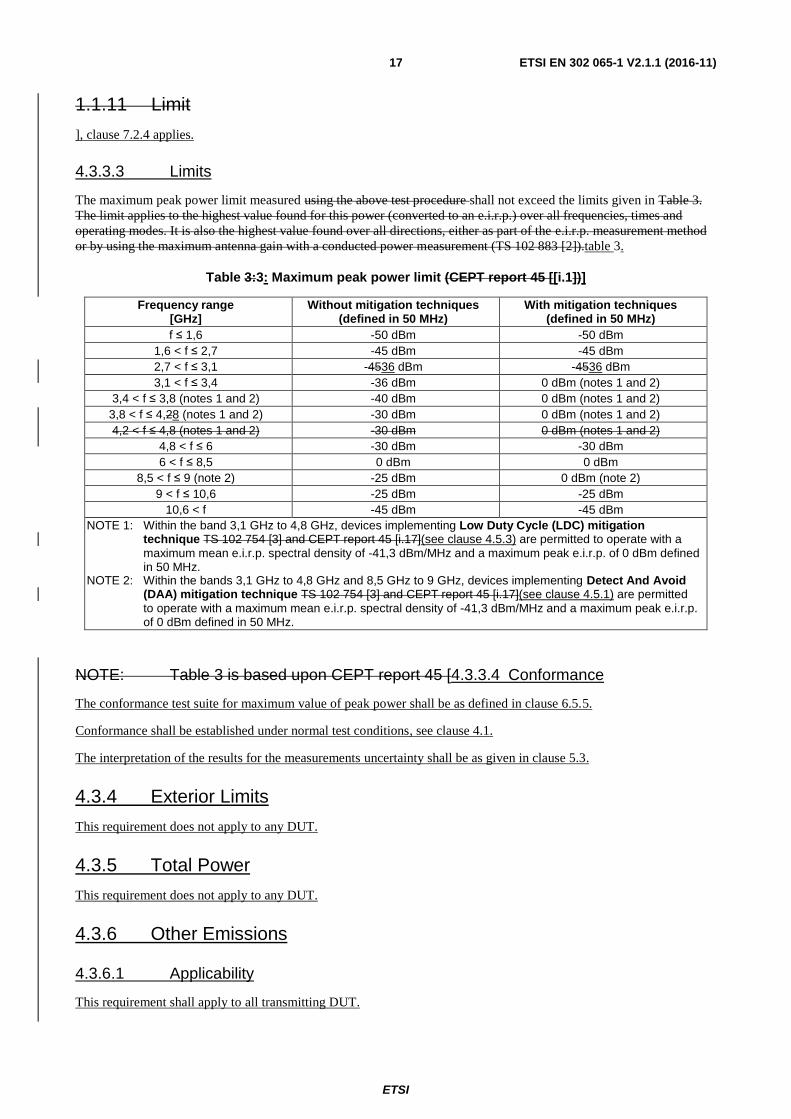
The maximum peak power limit measured using the above test procedure shall not exceed the limits given in Table 3.
The limit applies to the highest value found for this power (converted to an e.i.r.p.) over all frequencies, times and
operating modes. It is also the highest value found over all directions, either as part of the e.i.r.p. measurement method
or by using the maximum antenna gain with a conducted power measurement (TS 102 883 [2]).table 3.
Table 3:3: Maximum peak power limit (CEPT report 45 [[i.1])]
Frequency range [GHz]
Without mitigation techniques (defined in 50 MHz)
With mitigation techniques (defined in 50 MHz)
f ≤ 1,6 -50 dBm -50 dBm
1,6 < f ≤ 2,7 -45 dBm -45 dBm
2,7 < f ≤ 3,1 -4536 dBm -4536 dBm
3,1 < f ≤ 3,4 -36 dBm 0 dBm (notes 1 and 2)
3,4 < f ≤ 3,8 (notes 1 and 2) -40 dBm 0 dBm (notes 1 and 2)
3,8 < f ≤ 4,28 (notes 1 and 2) -30 dBm 0 dBm (notes 1 and 2)
4,2 < f ≤ 4,8 (notes 1 and 2) -30 dBm 0 dBm (notes 1 and 2)
4,8 < f ≤ 6 -30 dBm -30 dBm
6 < f ≤ 8,5 0 dBm 0 dBm
8,5 < f ≤ 9 (note 2) -25 dBm 0 dBm (note 2)
9 < f ≤ 10,6 -25 dBm -25 dBm
10,6 < f -45 dBm -45 dBm
NOTE 1: Within the band 3,1 GHz to 4,8 GHz, devices implementing Low Duty Cycle (LDC) mitigation technique TS 102 754 [3] and CEPT report 45 [i.17](see clause 4.5.3) are permitted to operate with a
maximum mean e.i.r.p. spectral density of -41,3 dBm/MHz and a maximum peak e.i.r.p. of 0 dBm defined in 50 MHz.
NOTE 2: Within the bands 3,1 GHz to 4,8 GHz and 8,5 GHz to 9 GHz, devices implementing Detect And Avoid (DAA) mitigation technique TS 102 754 [3] and CEPT report 45 [i.17](see clause 4.5.1) are permitted
to operate with a maximum mean e.i.r.p. spectral density of -41,3 dBm/MHz and a maximum peak e.i.r.p. of 0 dBm defined in 50 MHz.
NOTE: Table 3 is based upon CEPT report 45 [4.3.3.4 Conformance
The conformance test suite for maximum value of peak power shall be as defined in clause 6.5.5.
Conformance shall be established under normal test conditions, see clause 4.1.
The interpretation of the results for the measurements uncertainty shall be as given in clause 5.3.
4.3.4 Exterior Limits
This requirement does not apply to any DUT.
4.3.5 Total Power
This requirement does not apply to any DUT.
4.3.6 Other Emissions
4.3.6.1 Applicability
This requirement shall apply to all transmitting DUT.
ETSI
ETSI EN 302 065-1 V2.1.1 (2016-11) 18
4.3.6.2 Description
The description in ETSI EN 303 883 [1]. ], clause 7.2.5 applies.
4.3.6.3 Limits
The Commission Decision 2007/131/EC on UWB [i.8] is currently under revision. The amended EC/DEC is
expected within 2014.
For pulse based modulation the equivalent isotropically radiated power reading on the spectrum analyser can be directly
related to the peak power limit when a spectrum analyser resolution bandwidth of 50 MHz is used for the
measurements. If a spectrum analyser resolution bandwidthany of X MHz is used instead, the maximum peak power
limit shall be scaled down by a factor of 20 log (50/X), where X represents the measurement bandwidth used.
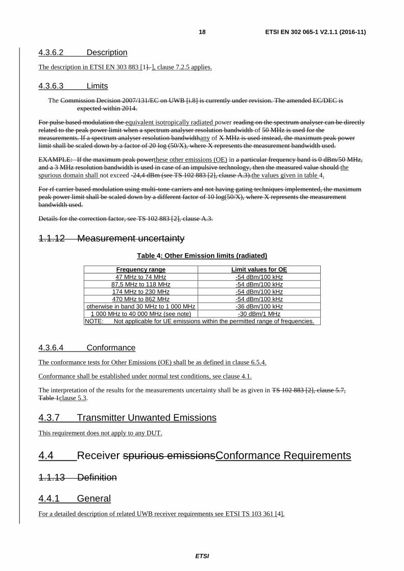
EXAMPLE: If the maximum peak powerthese other emissions (OE) in a particular frequency band is 0 dBm/50 MHz,
and a 3 MHz resolution bandwidth is used in case of an impulsive technology, then the measured value should the
spurious domain shall not exceed -24,4 dBm (see TS 102 883 [2], clause A.3).the values given in table 4.
For rf carrier based modulation using multi-tone carriers and not having gating techniques implemented, the maximum
peak power limit shall be scaled down by a different factor of 10 log(50/X), where X represents the measurement
bandwidth used.
Details for the correction factor, see TS 102 883 [2], clause A.3.
1.1.12 Measurement uncertainty
Table 4: Other Emission limits (radiated)
Frequency range Limit values for OE
47 MHz to 74 MHz -54 dBm/100 kHz
87,5 MHz to 118 MHz -54 dBm/100 kHz
174 MHz to 230 MHz -54 dBm/100 kHz
470 MHz to 862 MHz -54 dBm/100 kHz
otherwise in band 30 MHz to 1 000 MHz -36 dBm/100 kHz
1 000 MHz to 40 000 MHz (see note) -30 dBm/1 MHz
NOTE: Not applicable for UE emissions within the permitted range of frequencies.
4.3.6.4 Conformance
The conformance tests for Other Emissions (OE) shall be as defined in clause 6.5.4.
Conformance shall be established under normal test conditions, see clause 4.1.
The interpretation of the results for the measurements uncertainty shall be as given in TS 102 883 [2], clause 5.7,
Table 1clause 5.3.
4.3.7 Transmitter Unwanted Emissions
This requirement does not apply to any DUT.
4.4 Receiver spurious emissionsConformance Requirements
1.1.13 Definition
4.4.1 General
For a detailed description of related UWB receiver requirements see ETSI TS 103 361 [4].
ETSI
ETSI EN 302 065-1 V2.1.1 (2016-11) 19
4.4.2 Receiver spurious emissions
4.4.2.1 Applicability
Receiver spurious emission testing shall apply only when the equipment can work in a receive-only mode or is a
receive-only device.
NOTE: Otherwise receiver spurious emissions are measured as part of the other emissions, see clause 4.3.8.
4.4.2.2 Description
Receiver spurious emissions are emissions at any frequency when the equipment is in receive mode. Consequently,
receiver spurious emission testing applies only when the equipment can work in a receive-only mode.
1.1.14 Test procedure
The radiated test procedures as defined in clause 7.6 shall be used.
1.1.15 Limit
4.4.2.3 Limits
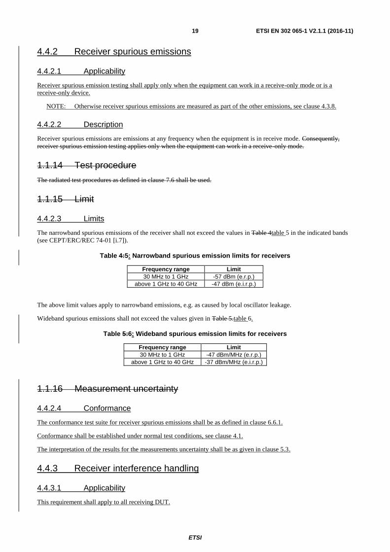
The narrowband spurious emissions of the receiver shall not exceed the values in Table 4table 5 in the indicated bands
(see CEPT/ERC/REC 74-01 [i.7]).
Table 4:5: Narrowband spurious emission limits for receivers
Frequency range Limit
30 MHz to 1 GHz -57 dBm (e.r.p.)
above 1 GHz to 40 GHz -47 dBm (e.i.r.p.)
The above limit values apply to narrowband emissions, e.g. as caused by local oscillator leakage.
Wideband spurious emissions shall not exceed the values given in Table 5.table 6.
Table 5:6: Wideband spurious emission limits for receivers
Frequency range Limit
30 MHz to 1 GHz -47 dBm/MHz (e.r.p.)
above 1 GHz to 40 GHz -37 dBm/MHz (e.i.r.p.)
1.1.16 Measurement uncertainty
4.4.2.4 Conformance
The conformance test suite for receiver spurious emissions shall be as defined in clause 6.6.1.
Conformance shall be established under normal test conditions, see clause 4.1.
The interpretation of the results for the measurements uncertainty shall be as given in clause 5.3.
4.4.3 Receiver interference handling
4.4.3.1 Applicability
This requirement shall apply to all receiving DUT.

ETSI
ETSI EN 302 065-1 V2.1.1 (2016-11) 20
4.4.3.2 Description
Interferer signal handling, defined as the capability of the device to operate as intended in the presence of interferers, is
the receiver parameter for UWB applications.
Operation as intended is evaluated using a performance criterion. For common applications, recommended performance
criteria and test cases are defined in clause 9.4 of ETSI TS 103 361 [4]. For other applications, the manufacturer shall
choose an appropriate performance criterion according to clause 9.2.1 of ETSI TS 103 361 [4]. The performance
criterion shall be stated in the user manual (see clause 9.2.2 of ETSI TS 103 361 [4]).
4.4.3.3 Limits
The level of performance of the chosen performance criterion shall meet the minimum requirement defined in clause 9
of ETSI TS 103 361 [4].
4.4.3.4 Conformance
The conformance test suite for receiver interference handling shall be as defined in clause 6.6.2.
Conformance shall be established under normal test conditions, see clause 4.1.
The interpretation of the results for the measurements uncertainty shall be as given in TS 102 883 [2],
clause 5.7, Table 1clause 5.3.
4.5 Requirements for Spectrum Access
4.5.1 Detect Andand Avoid (DAA)
1.1.17 Definition
Detect And Avoid (DAA) is a technology used to protect radio communication services by avoiding co channel
operation.
NOTE: Before transmitting, a system should sense the channel within its operative bandwidth in order to detect the possible presence of other systems. If another system is detected, the first system should avoid transmission until the detected system disappears (TS 102 902 [4.5.1.1 Applicability
This requirement shall apply to all devices that implement the DAA mitigation technique to avail themselves of the
relaxed limits in Note 2 of table 2 (clause 4.3.2.3) and in Note 2 of table 3 (clause 4.3.3.3).
4.5.1.2 Description
The description in ETSI EN 303 883 [1]).
1.1.18 Test procedure
DAA Test Procedure shall be done as given in TS 102 754 [3], Annex D.
1.1.19 Limit
], clause 7.2.8 applies.
4.5.1.3 Limits
Limits for the DAA parameters sets shall be as given in ETSI TS 102 754 [2], Annexesannexes A to C.

ETSI
ETSI EN 302 065-1 V2.1.1 (2016-11) 21
1.1.20 Measurement Tolerance
Measurement tolerance for detection probabilities4.5.1.4 Conformance
The conformance test suite for the detect and avoid (DAA) shall be as defined in clause 6.7.1.
Conformance shall be established under normal test conditions, see clause 4.1.
The interpretation of the results for the measurements uncertainty shall be as given in TS 102 754 [3], Annexes A to
Cclause 5.3.
4.5.2 Listen-Before-Talk (LBT)
This requirement does not apply to any DUT.
4.5.3 Low Duty Cycle (LDC)
1.1.21 Definition
Duty Cycle is the defined as the cumulative transmitter on time over a defined period of time, which is the observation
period.
1.1.22 Test procedure
The manufacturer shall provide sufficient information for determining compliance with the limits given in Table 6.
1.1.23 Limit
4.5.3.1 Applicability
This requirement shall apply to all devices that implement the LDC mitigation technique to avail themselves of the
relaxed limits in note 1 of table 2 (clause 4.3.2.3) and note 1 of table 3 (clause 4.3.3.3).
4.5.3.2 Description
The description in ETSI EN 303 883 [1], clause 7.2.9 applies.
4.5.3.3 Limits
The baseline limits for LDC shall be as given in Table 6. These values are defined in ECC/DEC/(06)04 [i.2].table 7.
Table 6:7: Baseline limits for low duty cycle [i.2]
Parameter Limit
Maximum transmitter on time Ton max 5 ms per transmission
Mean transmitter off time Toff mean ≥ 38 ms (averaged over 1 s)
Sum transmitter off time ∑ Toff > 950 ms per second
Sum transmitter on time ∑ Ton < 18 s per hour
Equivalent mitigationNOTE: An LDC trade off, power versus time, as described in Annex C, shall be seen as an equivalent mitigation technique according to [i.6]; details see CEPT report 45 [i.8], clause 3.1.1.
4.5.3.4 Conformance
The conformance test suite for Low Duty Cycle shall be as defined in clause 6.7.3.

ETSI
ETSI EN 302 065-1 V2.1.1 (2016-11) 22
Conformance shall be established under normal test conditions see clause 4.1.
The interpretation of the results for the measurements uncertainty shall be as given in clause 5.3.
4.6 Antenna Requirements
These requirements do not apply to any DUT.
4.7 Other Requirements and Mitigation techniques
1.1.24 Equivalent mitigation techniques and LDC limits
Different mitigation techniques and mitigation factors can be taken into account for the calculation of the maximum
allowed TX power of a UWB radio device as long as the reached mitigation factors are equivalent or higher than the
mitigation factors reached using the presented techniques which have been accepted by the CEPT/ECC (e.g. ECC
report 120 [i.7].
EXAMPLE: Deployment of the radio device on a vehicle, which operates only in a restricted indoor area with
higher wall attenuation, shielding or the deployment and installation of the UWB system in a
controlled manner. The additional mitigation factors need to be weighed against the specific
services to be protected and a similar approach has to be taken like e.g. in ECC report 120 [i.7].
The manufacturer shall provide These requirements do not apply to any DUT.
5 Testing for compliance with the transmission emissiontechnical requirements
5.1 Environmental conditions for testing
Tests defined in the present document shall be carried out at one or more representative point(s) within the boundary
limits in Tables 2 and 3 when using equivalent mitigation techniquesof the declared operational environmental profile.
NOTE: Regulations in the Commission Decision 2007/131/EC [i.8] and its amendment allow for other equivalent
mitigation techniques to be used across all frequency bands, where these offer at least equivalent
protection to that provided by the limits in the decision.
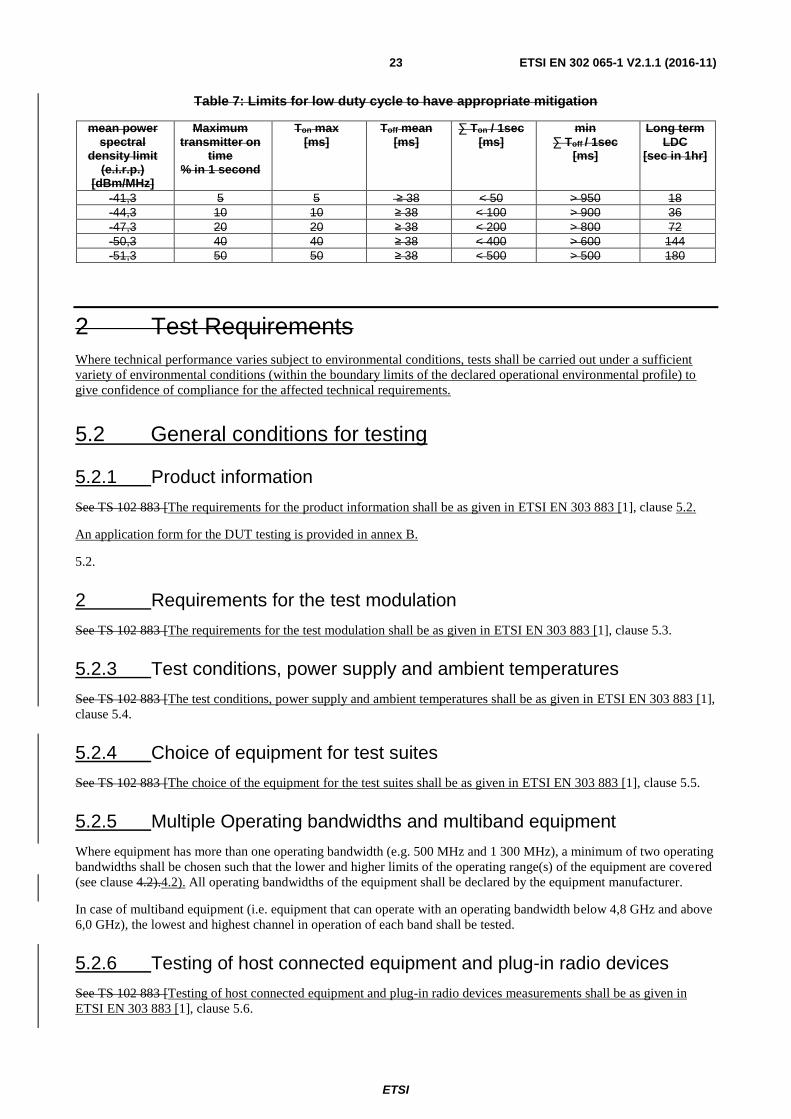
Based on CEPT report 45 [i.17] the combinations of LDC limits and the transmitter emission limits as shown in
Table 7, may give an equivalent protection as the current baseline LDC limits (see ECC/DEC/(06)04 [i.2], Table 6).
1.1.24.1 Test procedure
The manufacturer shall provide sufficient information for determining compliance with the limits given in Table 7.
1.1.24.2 Limit
The limits for equivalent LDC shall be as given in Table 7. These values are defined in CEPT report 45 [i.17].
ETSI
ETSI EN 302 065-1 V2.1.1 (2016-11) 23
Table 7: Limits for low duty cycle to have appropriate mitigation
mean power spectral
density limit (e.i.r.p.)
[dBm/MHz]
Maximum transmitter on
time % in 1 second
Ton max [ms]
Toff mean [ms]
∑ Ton / 1sec [ms]
min ∑ Toff / 1sec
[ms]
Long term LDC
[sec in 1hr]
-41,3 5 5 ≥ 38 < 50 > 950 18
-44,3 10 10 ≥ 38 < 100 > 900 36
-47,3 20 20 ≥ 38 < 200 > 800 72
-50,3 40 40 ≥ 38 < 400 > 600 144
-51,3 50 50 ≥ 38 < 500 > 500 180
2 Test Requirements
Where technical performance varies subject to environmental conditions, tests shall be carried out under a sufficient
variety of environmental conditions (within the boundary limits of the declared operational environmental profile) to
give confidence of compliance for the affected technical requirements.
5.2 General conditions for testing
5.2.1 Product information
See TS 102 883 [The requirements for the product information shall be as given in ETSI EN 303 883 [1], clause 5.2.
An application form for the DUT testing is provided in annex B.
5.2.
2 Requirements for the test modulation
See TS 102 883 [The requirements for the test modulation shall be as given in ETSI EN 303 883 [1], clause 5.3.
5.2.3 Test conditions, power supply and ambient temperatures
See TS 102 883 [The test conditions, power supply and ambient temperatures shall be as given in ETSI EN 303 883 [1],
clause 5.4.
5.2.4 Choice of equipment for test suites
See TS 102 883 [The choice of the equipment for the test suites shall be as given in ETSI EN 303 883 [1], clause 5.5.
5.2.5 Multiple Operating bandwidths and multiband equipment
Where equipment has more than one operating bandwidth (e.g. 500 MHz and 1 300 MHz), a minimum of two operating
bandwidths shall be chosen such that the lower and higher limits of the operating range(s) of the equipment are covered
(see clause 4.2).4.2). All operating bandwidths of the equipment shall be declared by the equipment manufacturer.
In case of multiband equipment (i.e. equipment that can operate with an operating bandwidth below 4,8 GHz and above
6,0 GHz), the lowest and highest channel in operation of each band shall be tested.
5.2.6 Testing of host connected equipment and plug-in radio devices
See TS 102 883 [Testing of host connected equipment and plug-in radio devices measurements shall be as given in
ETSI EN 303 883 [1], clause 5.6.

ETSI
ETSI EN 302 065-1 V2.1.1 (2016-11) 24
5.3 Interpretation of the measurement results
The interpretation 5.3.0 General
Interpretation of the results for the measurements described in the present document shall be as follows:
1) the measured value related to the corresponding limit shall be used to decide whether equipment meets the
requirements of the present document;
2) the measurement uncertainty value for the measurement of each parameter shall be recorded;
3) the recorded value of the measurement uncertainty shall be wherever possible, for each measurement, equal to
or lower than the figures in Table 8, and the interpretation procedure specifiedresults shall be as given in
clauses 5.6.1 and 5.6.2 shall be used.
For the test methods, according to the present document, the measurement uncertainty figures shall be calculated in
accordance with the guidance provided in TR 100 028 [4] and shall correspond to an expansion factor (coverage factor)
k = 1,96 or k = 2 (which provide confidence levels of respectively 95 % and 95,45 % in the case where the distributions
characterizing the actual measurement uncertainties are normal (Gaussian)).
Table 8 is based on such expansion factors.
Table 8: Maximum measurement uncertainty (TS 102ETSI EN 303 883 [1])], clause 5.7.
Parameter Uncertainty
Radio Frequency ±1 x 10⁻⁵
all emissions, radiated ±6 dB (see note)
Conducted ±3 dB
temperature ±1 C
Humidity ±5 %
DC and low frequency voltages ±3 %
NOTE: For radiated emissions measurements below 2,7 GHz and above 10,6 GHz it may not be possible to reduce measurement uncertainty to the levels specified in Table 1 (due to the very low signal level limits and the consequent requirement for high levels of amplification across wide bandwidths). In these cases alone it is acceptable to employ the alternative interpretation procedure specified in clause 5.6.2.
5.3.1 Measurement uncertainty is equal to or less than maximum acceptable uncertainty
The interpretation of the results when comparing measurement values with specification limits shall be as follows:
a) When the measured value exceeds the limit value within the range of theIf measurement uncertainty the
equipment under test meets the requirements of the present document.
The measurementis equal to or less than maximum acceptable uncertainty calculated by the test technician carrying out
the measurementinterpretation shall be recordedas given in the test reportETSI EN 303 883 [1], clause 5.7.2.
b) The measurement uncertainty calculated by the test technician may be a maximum value for a range of values
of measurement, or may be the measurement uncertainty for the specific measurement undertaken. The
method used shall be recorded in the test report.

ETSI
ETSI EN 302 065-1 V2.1.1 (2016-11) 25
5.3.2 Measurement uncertainty is greater than maximum acceptable uncertainty
The interpretation of the results when comparing measurement values with specification limits shall be as follows:
a) When the measured value plus the difference between the maximum acceptable measurement uncertainty and
the measurement uncertainty calculated by the test technician does not exceed the limit value plus the
maximum acceptable measurement uncertainty the equipment under test meets the requirements of the present
document.
b) When the measured value plus the difference between the maximum acceptable measurement uncertainty and
the measurement uncertainty calculated by the test technician exceeds the limit value within the range of the
measurement uncertainty the equipment under test does not meet the requirements of the present document.
c) The measurement uncertainty calculated by the test technician carrying out the measurement shall be recorded
in the test report.
d) The measurement uncertainty calculated by the test technician may be a maximum value for a range of values
of measurement, or may be the measurement uncertainty for the specific measurement untaken. The method
used shall be recorded in the test report.
2.1 Emissions
UWB transmitters emit very low power radio signals, comparable with the power of spurious emissions from digital
and analogue circuitry. If it can be clearly demonstrated that an emission from the ultra-wideband radio device is not the
ultra-wideband emission identified in clause If measurement uncertainty is greater than maximum acceptable
uncertainty the interpretation shall be as given in ETSI EN 303 883 [1 (e.g. by disabling the radio device's UWB
transmitter or disconnecting and terminating, internally or externally the antenna of the device) or it can clearly be
demonstrated that it is impossible to differentiate between other emissions and the UWB transmitter emissions, that
emission or aggregated emissions shall be considered against the receiver spurious emissions limits defined in the
relevant harmonized standard.
See TS 102 883 [], clause 5.7.3.
5.3.3 Emissions
The provisions of ETSI EN 303 883 [1], clauses 7.2.5 and 7.2.6 and EN 301 489-33 [5].
3 Test setups and procedures
], clause 5.8 shall apply.
6 Conformance test suits
6.1 Introduction
In this clause the general setup of a test bed for the test of UWB equipment will be described.
3.1 Introduction
See TS 102 883 [A detailed introduction shall be considered as in ETSI EN 303 883 [1], clause 6.1.

ETSI
ETSI EN 302 065-1 V2.1.1 (2016-11) 26
6.2 Initial Measurement steps
See TS 102 883 [Initial measurement steps shall be done as described in ETSI EN 303 883 [1], clause 6.2.
6.3 Radiated measurements
6.3.1 General
See TS 102The provisions of ETSI EN 303 883 [1], clause 6.3.1 shall apply.
6.3.2 Test sites and general arrangements for measurements involving the use of radiated fields
See TS 102The provisions of ETSI EN 303 883 [1], clause 6.3.2 shall apply.
6.3.3 Guidance on the use of a radiation test site
See TS 1026.3.3.1 General
The provisions of ETSI EN 303 883 [1], clause 6.3.3 shall apply.
6.3.3.2 Range length.
The range length for all these types of test facility shall be adequate to allow for testing in the far field of the EUT i.e. it
shall be equal to or exceed:
2212 dd
Where:
d1 is the largest dimension of the EUT/dipole after substitution (m);
d2 is the largest dimensionThe provisions of the test antenna (m);
is the test frequency wavelength (m).
It should be noted that in the substitution part of this measurement, where both test and substitution antennas are half
wavelength dipoles, this minimum range length for far-field testing would be:
2
It should be noted in test reports when either of these conditions is not met so that the additional measurement
uncertainty can be incorporated into the results.
NOTE 1: For the fully anechoic chamber, no part of the volume of the EUT should, at any angle of rotation of the
turntable, fall outside the "quiet zone" of the chamber at the nominal frequency of the test.
NOTE 2: The "quiet zone" is a volume within the anechoic chamber (without a ground plane) in which a specified
performance has either been proven by test, or is guaranteed by the designer/manufacturer. The specified
performance is usually the reflectivity of the absorbing panels or a directly related parameter (e.g. signal
uniformity in amplitude and phase). It should be noted however that the defining levels of the quiet zone
tend to vary.
It is not necessary to measure at ranges larger than 3 m, because sufficient accuracy is achieved even for a whole car.
Larger distances lead to sensitivity issues for the exterior limit, which need to be taken into account. More information
about the impact of the distance on the measurement accuracy can be found in TR 103 086 [i.5].

ETSI
ETSI EN 302 065-1 V2.1.1 (2016-11) 27
3.1.1 Coupling of signals
See TS 102ETSI EN 303 883 [1], clause 6.3.43.5 shall apply.
6.3.4 Coupling of signals
The provisions of ETSI EN 303 883 [1], clause 6.3.4 shall apply.
6.3.5 Standard test methods
Three test methods are defined for determining the radiated power of a radio device. Each method is further divided into
to two procedures for calibrated and not calibrated measurement setups.
6.3.5.1 Generic measurement method
6.3.5.1.1 Calibrated setup
The measurement receiver, test antenna and all associated equipment (e.g. cables, filters, amplifiers, etc.) shall have
been recently calibrated against known standards at all the frequencies on which measurements of the equipment are to
be made. A suggested calibration method is given in clause provisions of ETSI EN 303 883 [1.], clause 6.3.5.2 shall
apply.
If an anechoic chamber with conductive ground plane is used, the ground shall be covered by absorbing material in the
area of the direct ground reflection from the DUT to the test antenna.
On a test site according to clause 6.3, the equipment shall be placed at the specified height on a support, and in the
position closest to normal use as declared by the provider. If the maximum of the antenna/transmission pattern is not
known a full spherical scan according to clause 6.3.5.2 or 6.3.5.3 shall be performed.
The test antenna shall be oriented initially for vertical polarization and shall be chosen to correspond to the frequency of
the transmitter.
The output of the test antenna shall be connected to the spectrum analyser via whatever (fully characterized) equipment
is required to render the signal measurable (e.g. amplifiers).
The transmitter shall be switched on, if possible without modulation, and the spectrum analyser shall be tuned to the
frequency of the transmitter under test.
The test antenna shall be raised and lowered through the specified range of height until a maximum signal level is
detected by the spectrum analyser.
The transmitter shall then be rotated through 360° in the horizontal plane, until the maximum signal level is detected by
the spectrum analyser.
The test antenna shall be raised and lowered again through the specified range of height until a maximum signal level is
detected by the spectrum analyser.
The test antenna shall be rotated to horizontal polarization and the measurement procedure shall be repeated.
The maximum signal level detected by the spectrum analyser shall be noted and converted into the radiated power by
application of the pre-determined calibration coefficients for the equipment configuration used.
6.3.5.1.2 Substitution method
On a test site, selected from clause 6.3.2, the equipment shall be placed at the specified height on a support, as specified
in clause 6.3.2, and in the position closest to normal use as declared by the provider. If the maximum of the
antenna/transmission pattern is not known a full spherical scan according to clause The provisions of ETSI EN 303 883
[1 or 6.3.5.3 shall be performed.
The test antenna shall be oriented initially for vertical polarization and shall be chosen to correspond to the frequency of
the transmitter.

ETSI
ETSI EN 302 065-1 V2.1.1 (2016-11) 28
The output of the test antenna shall be connected to the spectrum analyser.
The transmitter shall be switched on, if possible without modulation, and the measuring receiver shall be tuned to the
frequency of the transmitter under test.
The test antenna shall be raised and lowered through the specified range of height until a maximum signal level is
detected by the spectrum analyser.
The transmitter shall then be rotated through 360° in the horizontal plane, until the maximum signal level is detected by
the spectrum analyser.
The test antenna shall be raised and lowered again through the specified range of height until a maximum signal level is
detected by the spectrum analyser.
The maximum signal level detected by the spectrum analyser shall be noted.
The transmitter shall be replaced by a substitution antenna as defined in clause 6.3.2.4 of TS 102 883 [2].
The substitution antenna shall be orientated for vertical polarization. The substitution antenna shall be connected to a
calibrated signal generator.
If necessary, the input attenuator setting of the spectrum analyser shall be adjusted in order to increase the sensitivity of
the spectrum analyser.
The test antenna shall be raised and lowered through the specified range of height to ensure that the maximum signal is
received. When a test site according clause 6.3.2.1 in TS 102 883 [2] is used, the height of the antenna shall not be
varied.
The input signal to the substitution antenna shall be adjusted to the level that produces a level detected by the spectrum
analyser, that is equal to the level noted while the transmitter radiated power was measured, corrected for the change of
input attenuator setting of the spectrum analyser.
The input level to the substitution antenna shall be recorded as power level, corrected for any change of input attenuator
setting of the spectrum analyser.
The measurement shall be repeated with the test antenna and the substitution antenna orientated for horizontal
polarization.
The measure of the radiated power of the radio device is the larger of the two levels recorded at the input to the
substitution antenna, corrected for gain of the substitution antenna if necessary.
3.1.1.1 Spherical scan with automatic test antenna placement
Figure 1 shows the spherical measurement method using automatic test antenna placement. The RX antenna moveable
and it is mounted for example on an automatic arm, which moves the antenna stepwise on a sphere around the DUT.
Figure 1: Spherical scan setup using automatic test antenna placement
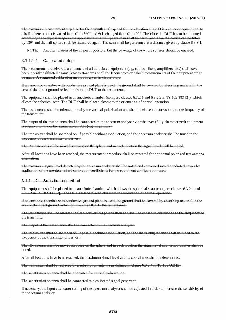
ETSI
ETSI EN 302 065-1 V2.1.1 (2016-11) 29
The maximum measurement step size for the azimuth angle ϕ and for the elevation angle Θ is smaller or equal to 5°. In
a half sphere scan ϕ is varied from 0° to 360° and Θ is changed from 0° to 90°. Therefore the DUT has to be mounted
according to the typical usage in the application. If a full sphere scan shall be performed, then the device can be tilted
by 180° and the half sphere shall be measured again. The scan shall be performed at a distance given by clause 6.3.3.1.
NOTE: Another relation of the angles is possible, but the coverage of the whole spheres should be ensured.
3.1.1.1.1 Calibrated setup
The measurement receiver, test antenna and all associated equipment (e.g. cables, filters, amplifiers, etc.) shall have
been recently calibrated against known standards at all the frequencies on which measurements of the equipment are to
be made. A suggested calibration method is given in clause 6.3.6.
If an anechoic chamber with conductive ground plane is used, the ground shall be covered by absorbing material in the
area of the direct ground reflection from the DUT to the test antenna.
The equipment shall be placed in an anechoic chamber (compare clauses 6.3.2.1 and 6.3.2.2 in TS 102 883 [2]), which
allows the spherical scan. The DUT shall be placed closest to the orientation of normal operation.
The test antenna shall be oriented initially for vertical polarization and shall be chosen to correspond to the frequency of
the transmitter.
The output of the test antenna shall be connected to the spectrum analyser via whatever (fully characterized) equipment
is required to render the signal measurable (e.g. amplifiers).
The transmitter shall be switched on, if possible without modulation, and the spectrum analyser shall be tuned to the
frequency of the transmitter under test.
The RX antenna shall be moved stepwise on the sphere and in each location the signal level shall be noted.
After all locations have been reached, the measurement procedure shall be repeated for horizontal polarized test antenna
orientation.
The maximum signal level detected by the spectrum analyser shall be noted and converted into the radiated power by
application of the pre-determined calibration coefficients for the equipment configuration used.
3.1.1.1.2 Substitution method
The equipment shall be placed in an anechoic chamber, which allows the spherical scan (compare clauses 6.3.2.1 and
6.3.2.2 in TS 102 883 [2]). The DUT shall be placed closest to the orientation of normal operation.
If an anechoic chamber with conductive ground plane is used, the ground shall be covered by absorbing material in the
area of the direct ground reflection from the DUT to the test antenna.
The test antenna shall be oriented initially for vertical polarization and shall be chosen to correspond to the frequency of
the transmitter.
The output of the test antenna shall be connected to the spectrum analyser.
The transmitter shall be switched on, if possible without modulation, and the measuring receiver shall be tuned to the
frequency of the transmitter under test.
The RX antenna shall be moved stepwise on the sphere and in each location the signal level and its coordinates shall be
noted.
After all locations have been reached, the maximum signal level and its coordinates shall be determined.
The transmitter shall be replaced by a substitution antenna as defined in clause 6.3.2.4 in TS 102 883 [2].
The substitution antenna shall be orientated for vertical polarization.
The substitution antenna shall be connected to a calibrated signal generator.
If necessary, the input attenuator setting of the spectrum analyser shall be adjusted in order to increase the sensitivity of
the spectrum analyser.

ETSI
ETSI EN 302 065-1 V2.1.1 (2016-11) 30
If an anechoic chamber with a conductive ground plane is used, then the substitution antenna shall be moved to the
position of the previous maximum. The test antenna shall be moved around this position of the substitution antenna
within at least five times the wavelength of the center frequency on the sphere to find the local maximum.
The input signal to the substitution antenna shall be adjusted to the level that produces a level detected by the spectrum
analyser, that is equal to the level noted while the transmitter radiated power was measured, corrected for the change of
input attenuator setting of the spectrum analyser.
The input level to the substitution antenna shall be recorded as power level, corrected for any change of input attenuator
setting of the spectrum analyser.
The measurement shall be repeated with the test antenna and the substitution antenna orientated for horizontal
polarization.
The measure of the radiated power of the radio device is the larger of the two levels recorded at the input to the
substitution antenna, corrected for gain of the substitution antenna if necessary.
3.1.1.2 Spherical scan with rotating device
Instead of using an automatic arm, it is also possible to rotate and tilt the DUT (see Figure 2). Thus, the same sphere can
be measured as with the automatic arm. In contrast to the previous method Θ is changed from 0° to -90° for the half
sphere measurement. The distance d is given by clause 6.3.3.1.
Figure 2: Spherical scan setup with rotation and tilt of the DUT
3.1.1.2.1 Calibrated setup
The measurement receiver, test antenna and all associated equipment (e.g. cables, filters, amplifiers, etc.) shall have
been recently calibrated against known standards at all the frequencies on which measurements of the equipment are to
be made. A suggested calibration method is given in clause 6.3.6.
If an anechoic chamber with conductive ground plane is used, the ground shall be covered by absorbing material in the
area of the direct ground reflection from the DUT to the test antenna.
The equipment shall be placed in an anechoic chamber (compare clauses 6.3.2.1 and 6.3.2.2 in TS 102 883 [2]), which
allows the rotation and tilt of the DUT. The DUT shall be placed closest to the orientation of normal operation.
The test antenna shall be oriented initially for vertical polarization and shall be chosen to correspond to the frequency of
the transmitter.
The output of the test antenna shall be connected to the spectrum analyser via whatever (fully characterized) equipment
is required to render the signal measurable (e.g. amplifiers).
The transmitter shall be switched on, if possible without modulation, and the spectrum analyser shall be tuned to the
frequency of the transmitter under test.
The TX antenna shall be stepwise rotated and tilted that the sphere of interest is covered. The signal level shall be noted
in each location.
After all locations have been reached, the measurement procedure shall be repeated for horizontal polarized test antenna
orientation.

ETSI
ETSI EN 302 065-1 V2.1.1 (2016-11) 31
The maximum signal level detected by the spectrum analyser shall be determined and converted into the radiated power
by application of the pre-determined calibration coefficients for the equipment configuration used.
3.1.1.2.2 Substitution method
The equipment shall be placed in an anechoic chamber, which allows the rotation and tilt of the DUT. The DUT shall be
placed closest to the orientation of normal operation.
The test antenna shall be oriented initially for vertical polarization and shall be chosen to correspond to the frequency of
the transmitter.
The output of the test antenna shall be connected to the spectrum analyser.
The transmitter shall be switched on, if possible without modulation, and the measuring receiver shall be tuned to the
frequency of the transmitter under test.
The TX antenna shall be stepwise rotated and tilted that the sphere of interest is covered. The signal level shall be noted
in each orientation.
After all locations have been reached, the maximum signal level and the orientation of the DUT shall be noted.
The transmitter shall be replaced by a substitution antenna as defined in clause 6.3.2.4 in TS 102 883 [2].
The substitution antenna shall be orientated for vertical polarization and the length of the substitution antenna shall be
adjusted to correspond to the frequency of the transmitter.
The substitution antenna shall be connected to a calibrated signal generator.
If necessary, the input attenuator setting of the spectrum analyser shall be adjusted in order to increase the sensitivity of
the spectrum analyser.
If an anechoic chamber with a conductive ground plane is used, then the test antenna shall be raised and lowered
through the specified range of height that the maximum signal level is received.
The input signal to the substitution antenna shall be adjusted to the level that produces a level detected by the spectrum
analyser, that is equal to the level noted while the transmitter radiated power was measured, corrected for the change of
input attenuator setting of the spectrum analyser.
The input level to the substitution antenna shall be recorded as power level, corrected for any change of input attenuator
setting of the spectrum analyser.
The measurement shall be repeated with the test antenna and the substitution antenna orientated for horizontal
polarization.
The measure of the radiated power of the radio device is the larger of the two levels recorded at the input to the
substitution antenna, corrected for gain of the substitution antenna if necessary.
3.1.1.3 Spherical scan other methods
Other methods for spherical scans are allowed but it has to be ensured that the relevant sphere is full covert. Then again
the calibrated or substitution method shall be applied. The exact method for the scanning shall be described in the
measurement report.
], clause 6.3.5.3 shall apply.
6.3.6 Standard calibration method
See TS 102The provisions of ETSI EN 303 883 [1], clause 6.3.6 shall apply.

ETSI
ETSI EN 302 065-1 V2.1.1 (2016-11) 32
6.4 Conducted measurements
See TS 1026.4.1 General Setup
The provisions of ETSI EN 303 883 [1], clause 6.4 shall apply.
4 Test procedures for essential radio test suites
6.4.2 Specific Setup
This requirement does not apply to any DUT.
6.5 Conformance methods of measurement for transmitter
6.5.1 General
First the complete signal device shall be measured for:
the maximum mean power spectral density (e.i.r.p.);
the maximum peak power (e.i.r.p.);
the operating bandwidth(s);
the receiver spurious emissions;
Other emissionsEmissions (OE);
Low Duty Cycle (LDC);), when applicable;
Detect and avoidAnd Avoid (DAA), when applicable.
The following methods of measurement shall apply to the testing of stand-alone units and to the equipment
configurations identified in clause 5.5.5.2.6.
6.5.2 Method of measurements of the Ultra Wideband Emissions
Method of measurements of the Ultra Wideband Emissions shall be as given in TS 102ETSI EN 303 883 [1], clause 7.3.
6.5.3 Operating Bandwidth
Operating bandwidth measurements shall be performed as given in ETSI EN 303 883 [1], clause 7.4.2.
The results for fL, fH, fM, OBW, and fC shall be reported in the test report.
6.5.4 Mean power spectral density measurements
Mean power spectral density measurements shall be as given in TS 102ETSI EN 303 883 [1], clause 7.4.3.
PeakTo classify the Ultra wide band part (clause 4.3.2) and the other emissions (clause 4.3.6) of the radiated emission
the initial measurement steps given in ETSI EN 303 883 [1], clause 7.3.2 shall be used.
The measurement method used and the maximum observed value for the mean power spectral density shall be recorded
in the test report.
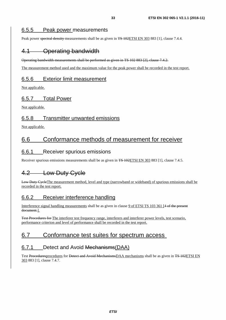
ETSI
ETSI EN 302 065-1 V2.1.1 (2016-11) 33
6.5.5 Peak power measurements
Peak power spectral density measurements shall be as given in TS 102ETSI EN 303 883 [1], clause 7.4.4.
4.1 Operating bandwidth
Operating bandwidth measurements shall be performed as given in TS 102 883 [2], clause 7.4.2.
The measurement method used and the maximum value for the peak power shall be recorded in the test report.
6.5.6 Exterior limit measurement
Not applicable.
6.5.7 Total Power
Not applicable.
6.5.8 Transmitter unwanted emissions
Not applicable.
6.6 Conformance methods of measurement for receiver
6.6.1 Receiver spurious emissions
Receiver spurious emissions measurements shall be as given in TS 102ETSI EN 303 883 [1], clause 7.4.5.
4.2 Low Duty Cycle
Low Duty CycleThe measurement method, level and type (narrowband or wideband) of spurious emissions shall be
recorded in the test report.
6.6.2 Receiver interference handling
Interference signal handling measurements shall be as given in clause 9 of ETSI TS 103 361 [4 of the present
document.].
Test Procedures for The interferer test frequency range, interferers and interferer power levels, test scenario,
performance criterion and level of performance shall be recorded in the test report.
6.7 Conformance test suites for spectrum access
6.7.1 Detect and Avoid Mechanisms(DAA)
Test Proceduresprocedures for Detect and Avoid MechanismsDAA mechanisms shall be as given in TS 102ETSI EN
303 883 [1], clause 7.4.7.
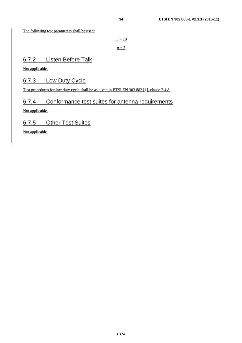
ETSI
ETSI EN 302 065-1 V2.1.1 (2016-11) 34
The following test parameters shall be used:
m = 10
n = 5
6.7.2 Listen Before Talk
Not applicable.
6.7.3 Low Duty Cycle
Test procedures for low duty cycle shall be as given in ETSI EN 303 883 [1], clause 7.4.8.
6.7.4 Conformance test suites for antenna requirements
Not applicable.
6.7.5 Other Test Suites
Not applicable.

ETSI
ETSI EN 302 065-1 V2.1.1 (2016-11) 35
Annex A (normative): HS Requirements and conformance Test specifications Table (HS-RTT)Relationship between the present document and the essential requirements of Directive 2014/53/EU
The HS Requirements and conformance Test specifications Table (HS-RTT) in Table A.1 serves a number of purposes,
as follows:
it provides a statement of all the requirements in words and by cross reference to (a) specific clause(s) in the
present document or to (a) specific clause(s) in (a) specific referenced document(s);
it provides a statement of all the test procedures corresponding to those requirements by cross reference to (a) specific
clause(s) inThe present document has been prepared under the Commission's standardisation request C(2015) 5376 final
[i.10] to provide one voluntary means of conforming to the essential requirements of Directive 2014/53/EU on the
harmonisation of the laws of the Member States relating to the making available on the market of radio equipment and
repealing Directive 1999/5/EC [i.1].
Once the present document or to (a) specific clause(s) in (a) specific referenced document(s);
it qualifies each requirement to be either:
- Unconditional: meaning that the requirement applies in all circumstances; or
- Conditional: meaning that the requirement is dependent on the manufacturer having chosen to support
optional functionality defined within the schedule.
cited in the case of Conditional requirements, it associatesOfficial Journal of the requirement with the
particular optional service or functionality;
it qualifies each test procedure to be either:
- Essential: meaning that it is included with the Essential Radio Test Suite and therefore the requirement
shall be demonstrated to be met in accordance with the referenced procedures;
Other: meaning that the test procedure is illustrative but other means of demonstratingEuropean Union under that
Directive, compliance with the requirement are permittednormative clauses of the present document given in table A.1
confers, within the limits of the scope of the present document, a presumption of conformity with the corresponding
essential requirements of that Directive, and associated EFTA regulations.
Table A.1: HS Requirements and conformance Test specifications Table (HS-RTT)Relationship between the present document and
the essential requirements of Directive 2014/53/EU
HarmonizedHarmonised Standard ETSI EN 302 065-1
The following requirements and test specifications are relevant to the presumption of conformity under the article 3.2 of the R&TTE Directive 2014/53/EU [Error! Reference source not found.]
Requirement Requirement Conditionality Test
specification
No Description Reference:
clauseClause No
U/C Condition E/O Reference:
clause No
1 Operating bandwidth 4.3.1 UC All transmitting devices E 7.5
2 Maximum value of mean power spectral density
4.3.2 UC All transmitting devices E 7.3
3 Maximum value of peak power 4.3.3 UC All transmitting devices E 7.4
4 Other emissions 4.3.6 C All transmitting devices
45 Receiver spurious emissions 4.4.2 C Applies only to equipment that can be operated in a receive-only mode
E 7.6
6 Receiver interference handling 4.4.3 C All receiving devices
5a7 Detect-and-avoid 4.5.1 C Applies only to equipment operating in the frequency band 3,1 GHz to 4,8 GHz and having DAA
E 7.8
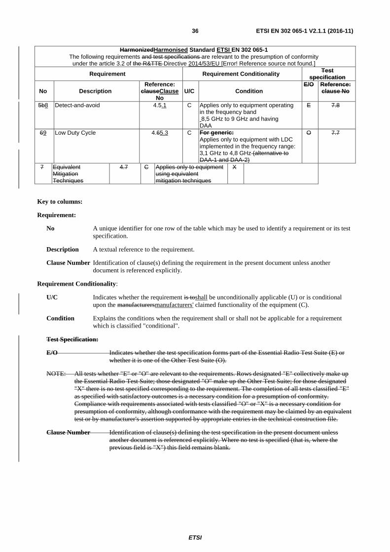
ETSI
ETSI EN 302 065-1 V2.1.1 (2016-11) 36
HarmonizedHarmonised Standard ETSI EN 302 065-1
The following requirements and test specifications are relevant to the presumption of conformity under the article 3.2 of the R&TTE Directive 2014/53/EU [Error! Reference source not found.]
Requirement Requirement Conditionality Test
specification
No Description Reference:
clauseClause No
U/C Condition E/O Reference:
clause No
5b8 Detect-and-avoid 4.5.1 C Applies only to equipment operating in the frequency band 8,5 GHz to 9 GHz and having DAA
E 7.8
69 Low Duty Cycle 4.65.3 C For generic:
Applies only to equipment with LDC implemented in the frequency range: 3,1 GHz to 4,8 GHz (alternative to DAA-1 and DAA-2)
O 7.7
7 Equivalent Mitigation Techniques
4.7 C Applies only to equipment using equivalent mitigation techniques
X
Key to columns:
Requirement:
No A unique identifier for one row of the table which may be used to identify a requirement or its test
specification.
Description A textual reference to the requirement.
Clause Number Identification of clause(s) defining the requirement in the present document unless another
document is referenced explicitly.
Requirement Conditionality:
U/C Indicates whether the requirement is toshall be unconditionally applicable (U) or is conditional
upon the manufacturersmanufacturers' claimed functionality of the equipment (C).
Condition Explains the conditions when the requirement shall or shall not be applicable for a requirement
which is classified "conditional".
Test Specification:
E/O Indicates whether the test specification forms part of the Essential Radio Test Suite (E) or
whether it is one of the Other Test Suite (O).
NOTE: All tests whether "E" or "O" are relevant to the requirements. Rows designated "E" collectively make up
the Essential Radio Test Suite; those designated "O" make up the Other Test Suite; for those designated
"X" there is no test specified corresponding to the requirement. The completion of all tests classified "E"
as specified with satisfactory outcomes is a necessary condition for a presumption of conformity.
Compliance with requirements associated with tests classified "O" or "X" is a necessary condition for
presumption of conformity, although conformance with the requirement may be claimed by an equivalent
test or by manufacturer's assertion supported by appropriate entries in the technical construction file.
Clause Number Identification of clause(s) defining the test specification in the present document unless
another document is referenced explicitly. Where no test is specified (that is, where the
previous field is "X") this field remains blank.

ETSI
ETSI EN 302 065-1 V2.1.1 (2016-11) 37
Annex BPresumption of conformity stays valid only as long as a reference to the present document is maintained in the
list published in the Official Journal of the European Union. Users of the present document should consult frequently
the latest list published in the Official Journal of the European Union.
Other Union legislation may be applicable to the product(s) falling within the scope of the present document.
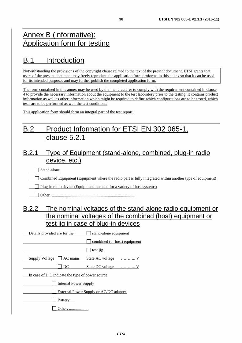
ETSI
ETSI EN 302 065-1 V2.1.1 (2016-11) 38
Annex B (informative): Application form for testing
B.1 Introduction
Notwithstanding the provisions of the copyright clause related to the text of the present document, ETSI grants that
users of the present document may freely reproduce the application form proforma in this annex so that it can be used
for its intended purposes and may further publish the completed application form.
The form contained in this annex may be used by the manufacturer to comply with the requirement contained in clause
4 to provide the necessary information about the equipment to the test laboratory prior to the testing. It contains product
information as well as other information which might be required to define which configurations are to be tested, which
tests are to be performed as well the test conditions.
This application form should form an integral part of the test report.
B.2 Product Information for ETSI EN 302 065-1, clause 5.2.1
B.2.1 Type of Equipment (stand-alone, combined, plug-in radio device, etc.)
Stand-alone
Combined Equipment (Equipment where the radio part is fully integrated within another type of equipment)
Plug-in radio device (Equipment intended for a variety of host systems)
Other ..................................................................................
B.2.2 The nominal voltages of the stand-alone radio equipment or the nominal voltages of the combined (host) equipment or test jig in case of plug-in devices
Details provided are for the: stand-alone equipment
combined (or host) equipment
test jig
Supply Voltage AC mains State AC voltage ……….. V
DC State DC voltage ……….. V
In case of DC, indicate the type of power source
Internal Power Supply
External Power Supply or AC/DC adapter
Battery
Other: ...................

ETSI
ETSI EN 302 065-1 V2.1.1 (2016-11) 39
B.3 Signal related Information for ETSI EN 302 065-1, clause 4.3
B.3.1 Introduction
In accordance with ETSI EN 302 065-1, clause 4.3, the following information is provided by the manufacturer.
B.3.2 Operating bandwidth(s) of the equipment
Operating bandwidth 1: ........... MHz to ........... MHz
Operating bandwidth 2: ........... MHz to ........... MHz
NOTE: Add more lines if more Frequency Ranges are supported.
B.3.3 The worst case mode for each of the following tests
NOTE: In this section specify the Operational mode and not the measured value. e.g. test mode 1, etc.
Operating bandwidth(s)
.........................................................................................
Mean Power Spectral Density / Peak Power Spectral Density / Other Emissions
.........................................................................................
B.4 RX test Information for ETSI EN 302 065-1, clause 4.4
B.4.1 Introduction
In accordance with ETSI EN 302 065-1, clause 4.4, the following information is provided by the manufacturer.
B.4.2 Performance criterion and level of performance
Performance criterion (e.g. accuracy, sensitivity)
.........................................................................................
Level of performance (e.g.for accuracy ±10 %, level of sensitivity)
.........................................................................................
B.4.3 Interfering signals
Frequency [MHz] Power [dBm] Type of signal (e.g. CW, CW with DC, other modulation)
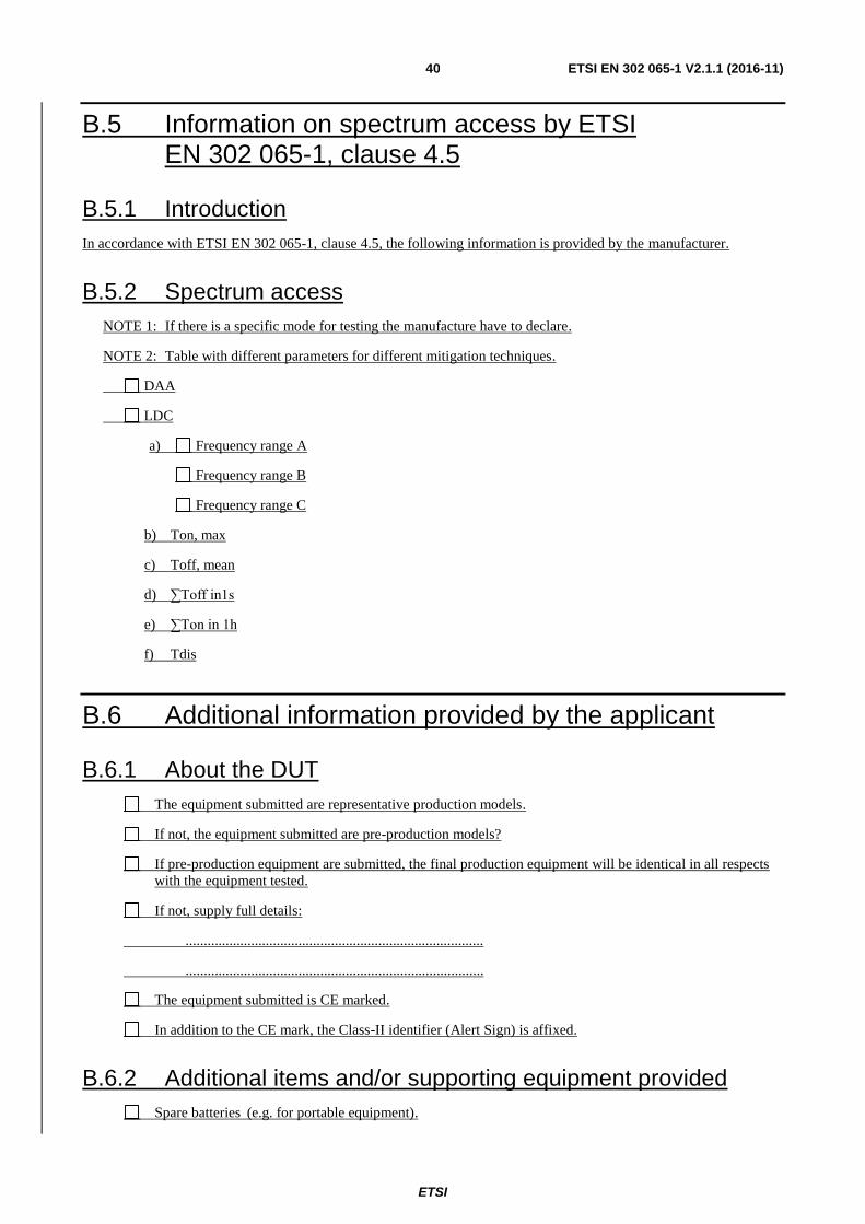
ETSI
ETSI EN 302 065-1 V2.1.1 (2016-11) 40
B.5 Information on spectrum access by ETSI EN 302 065-1, clause 4.5
B.5.1 Introduction
In accordance with ETSI EN 302 065-1, clause 4.5, the following information is provided by the manufacturer.
B.5.2 Spectrum access
NOTE 1: If there is a specific mode for testing the manufacture have to declare.
NOTE 2: Table with different parameters for different mitigation techniques.
DAA
LDC
a) Frequency range A
Frequency range B
Frequency range C
b) Ton, max
c) Toff, mean
d) ∑Toff in1s
e) ∑Ton in 1h
f) Tdis
B.6 Additional information provided by the applicant
B.6.1 About the DUT
The equipment submitted are representative production models.
If not, the equipment submitted are pre-production models?
If pre-production equipment are submitted, the final production equipment will be identical in all respects
with the equipment tested.
If not, supply full details:
..................................................................................
..................................................................................
The equipment submitted is CE marked.
In addition to the CE mark, the Class-II identifier (Alert Sign) is affixed.
B.6.2 Additional items and/or supporting equipment provided
Spare batteries (e.g. for portable equipment).

ETSI
ETSI EN 302 065-1 V2.1.1 (2016-11) 41
Battery charging device.
External Power Supply or AC/DC adapter.
Test Jig or interface box.
RF test fixture (for equipment with integrated antennas).
Host System Manufacturer: ....................
Model #: ....................
Model name: ....................
Combined equipment Manufacturer: ....................
Model #: ....................
Model name: ....................
User Manual.
Technical documentation (Handbook and circuit diagrams)

ETSI
ETSI EN 302 065-1 V2.1.1 (2016-11) 42
Annex C (normative): Equivalent mitigation techniques
C.1 Equivalent mitigation techniques and LDC limits
Different mitigation techniques and mitigation factors can be taken into account for the calculation of the maximum
allowed TX power of a UWB radio device as long as they reached mitigation factors are equivalent or higher than the
mitigation factors reached using the presented techniques which have been accepted by the CEPT/ECC (e.g. ECC
report 120 [i.3]).
EXAMPLE: Deployment of the radio device on a vehicle, which operates only in a restricted indoor area with
higher wall attenuation, shielding or the deployment and installation of the UWB system in a
controlled manner. The additional mitigation factors need to be weighed against the specific
services to be protected and a similar approach has to be taken like e.g. in ECC report 120 [i.3].
The manufacturer shall provide compliance with the transmission emission limits in tables 2 and 3 when using
equivalent mitigation techniques.
NOTE: Regulations in the Commission Decision 2007/131/EC [i.4] and its amendment allow for other equivalent
mitigation techniques to be used across all frequency bands, where these offer at least equivalent
protection to that provided by the limits in the decision.
Based on CEPT report 45 [i.8] the combinations of LDC limits and the transmitter emission limits as shown in
table C.1, may give an equivalent protection as the current baseline LDC limits (see ECC/DEC/(06)04 [i.2], table 6).
C.2 Test Procedure
The manufacturer shall provide sufficient information for determining compliance with the limits given in table C.1.
C.3 Limit
The limits for equivalent LDC shall be as given in table C.1. These values are defined in CEPT report 45 [i.8].
Table C.1: Limits for low duty cycle to have appropriate mitigation
mean power spectral
density limit (e.i.r.p.)
[dBm/MHz]
Maximum transmitter on
time % in 1 second
Ton max [ms]
Toff mean [ms]
∑ Ton / 1sec [ms]
min ∑ Toff / 1sec
[ms]
Long term LDC
[sec in 1hr]
-41,3 5 5 ≥ 38 < 50 > 950 18
-44,3 10 10 ≥ 38 < 100 > 900 36
-47,3 20 20 ≥ 38 < 200 > 800 72
-50,3 40 40 ≥ 38 < 400 > 600 144
-51,3 50 50 ≥ 38 < 500 > 500 180

ETSI
ETSI EN 302 065-1 V2.1.1 (2016-11) 43
Annex D (informative): Measurement antenna, preamplifier, and cable specifications
The radiated measurements set-up in Annex Bannex B of ETSI EN 303 883 [1] specifies the use of a horn antenna and
a wide--band high gain preamplifier above 1 GHz in order to measure the very low radiated power density level from
UWB equipment.
Table BD.1 gives examples of recommended data and features for the horn antenna and preamplifier to be used for the
test set-up.
Table BD.1: Recommended Hardware
Device Parameter Value
Preamplifier LNA
Bandwidth < 1 GHz to > 15 GHz
NF < 2,5 dB
Gain > 30 dB
Gain flatness across band ±1,5 dB
VSWR in/out across band < 2:1
Nominal impedance 50 Ω
RX Horn Antenna
3 dB bandwidth < 1 GHz to > 15 GHz
VSWR across band < 1,5:1
Gain (10GHz) > 16 dBi
Gain (8GHz) > 14 dBi
Gain (6GHz) > 12,5 dBi
Gain (2-5GHz) > 10 dBi
Nominal impedance 50 Ω
Cable
Nominal impedance 50 Ω
VSWR < 1,2:1
Shielding > 60 dB
Losses Take losses into account for total gain calculations
NOTE: The noise floor of the combined equipment should be at least 6 dB below the specified limits, but 10 dB would be optimal.

ETSI
ETSI EN 302 065-1 V2.1.1 (2016-11) 44
ETSI
ETSI EN 302 065-1 V2.1.1 (2016-11) 45
Annex CE (informative): Bibliography
ERA Report 2006-0713: "Conducted and radiated measurements for low level UWB emissions".
ETSI TR 102 070-2: "Electromagnetic compatibility and Radio spectrum Matters (ERM); Guide to the application of
harmonizedharmonised standards to multi-radio and combined radio and non-radio equipment; Part 2: Effective use of
the radio frequency spectrum".
ETSI TR 102 273 (V1.2.1) (all parts): "Electromagnetic compatibility and Radio spectrum Matters (ERM);
Improvement on Radiated Methods of Measurement (using test site) and evaluation of the corresponding measurement
uncertainties".
ETSI TR 101 538: "Electromagnetic compatibility and Radio spectrum Matters (ERM); Short Range Devices (SRD);
UWB location tracking devices in the railroad environment".
ETSI TS 103 085 (10-2012): "Electromagnetic compatibility and Radio spectrum Matters (ERM); Short Range Devices
(SRD) using Ultra Wide Band (UWB) for Location and Tracking railroad applications; RF conformance testing".
ETSI TS 103 060: "Electromagnetic compatibility and Radio spectrum Matters (ERM); Short Range Devices (SRD);
Method for a harmonized definition of Low Duty Cycle transmission (LDC) as a passive mitigation technique used by
short range devices and related conformance test methods".
Directive 1999/5/EC of the European Parliament and of the Council of 9 March 1999 on radio equipment and
telecommunications terminal equipment and the mutual recognition of their conformity (R&TTE Directive).
ETSI
ETSI EN 302 065-1 V2.1.1 (2016-11) 46
ETSI EN 301 489-33 (V2.1.1): "ElectroMagnetic Compatibility (EMC) standard for radio equipment and services;
Harmonised Standard covering the essential requirements of article 3.1b of the Directive 2014/53/EU; Part 33: Specific
conditions for Ultra Wide Band (UWB) devices".

ETSI
ETSI EN 302 065-1 V2.1.1 (2016-11) 47
Annex F (informative): Change history
Date Version Information about changes
April 2014 1.3.1 Last publication as HS under R&TTE
November 2016 2.1.1
Revision for compliance with Directive 2014/53/EU
Out-sourcing of standard measurement procedures into a separate EN 303 883 (V1.1.1)
More detailed description of receiver spurious emission requirements
New requirement on Interferer signal handling
New Annex B "Application form for testing"
New Annex C "Equivalent mitigation techniques"

ETSI
ETSI EN 302 065-1 V2.1.1 (2016-11) 48
History
Document history
V1.1.1 February 2008 Publication as ETSI EN 302 065
V1.2.1 October 2010 Publication as ETSI EN 302 065
V1.3.1 June 2013 EN Approval Procedure AP 20131015: 2013-06-17 to 2013-10-15
V1.3.1 February 2014 Vote V 20140408: 2014-02-07 to 2014-04-08
V1.3.1 April 2014 Publication
V2.1.0 April 2016 EN Approval Procedure AP 20160705: 2016-04-06 to 2016-07-05
V2.1.1 November 2016 Publication


![ETSI EN 300 065-1 V1[1].1.3 (2001-05)](https://static.fdocuments.in/doc/165x107/56d6bff21a28ab3016984e60/etsi-en-300-065-1-v1113-2001-05.jpg)