Estimation of Vehicle Clutch Torque Using Combined …acl.kaist.ac.kr/Thesis/2014ICCAS_HKS.pdf ·...
6
2014 14th International Conference on Control, Automation and Systems (ICCAS 2014) Oct. 22–25, 2014 in KINTEX, Gyeonggi-do, Korea Estimation of Vehicle Clutch Torque Using Combined Sliding Mode Observers and Unknown Input Observers Kyoungseok Han 1 , Seibum Choi 2* and Jiwon Oh 3 1 School of Mechanical Aerospace Systems Engineering, Division of Mechanical Engineering, KAIST, Daejeon,Korea (Tel: +82-42-350-4160; E-mail: [email protected]) 2 School of Mechanical Aerospace Systems Engineering, Division of Mechanical Engineering, KAIST, Daejeon,Korea (Tel: +82-42-350-4160; E-mail: [email protected]) * Corresponding author 3 School of Mechanical Aerospace Systems Engineering, Division of Mechanical Engineering, KAIST, Daejeon,Korea (Tel: +82-42-350-4160; E-mail: [email protected]) Abstract: Precise clutch control is a crucial factor in determining the ride quality of the production vehicle and its performance has been enhanced by accurate estimation of involved clutch torque or pressure, especially during gear changing phase (torque phase / inertia phase). Unfortunately, torque or pressure sensor is not available in production cars because of its cost, installation, and maintenance issues. This study mainly focuses on the accurate estimation of the clutch torques for the vehicles with automatic transmission using sliding mode observers and unknown input observers.Sliding mode observer is selected because of its applicability to nonlinear systems and characteristics of its robustness to model uncertainties. The required values for estimation include the engine map, torque converter characteristic curve, and various vehicle parameters such as gear ratio and inertia. Using the above-mentioned information, sliding mode observer is constructed without additional sensors. The proposed observer is validated by computer simulation using commercial software Matlab & Simulink. The estimated output shaft torque can be used as a reference for optimal clutch control and torque sensor which is not possible in the production car can be replaced with those developed observers. Keywords: clutch torque, output shaft torque, sliding mode observers, unknown input observers. 1. INTRODUCTION In both automatic transmission (AT) and automated manual transmission (AMT), the change of gear ratio proceeds while controlling the relevant clutches. This process is commonly referred to as clutch to clutch shift, in which one clutch engages and others disengage. Information of clutch torque or pressure, especially during a gear change, is crucial factors for enhancing ve- hicle ride quality. But clutch torque or pressure are un- measurable values on the majority of production cars be- cause of the cost, installation, and maintenance problem. Therefore, it is required to estimate a clutch torque with accessible values in production cars such as wheel speed , engine speed and output shaft speed with the sensors which are embedded in the car. For these reasons, several studies have been conducted to estimate various torques for optimal clutch control. [1]-[5], [8]. For example, R. A. Masmoudi et al. [1] utilized sliding mode observers to estimate output shaft torque. However, these estimation scheme doesn’t con- sider clutch torques which are essential to estimate output shaft torque. K. S. Yi et al. [2] employed adaptive slid- ing mode observers to estimate turbine torque which is output torque of the torque converter. In this paper, how- ever, turbine torque is assumed to be a known value with steady - state torque converter characteristic curves. In addition to the above-mentioned conventional observers, well known observers like Luenberger and Kalman filter are also used in linear system. However vehicle pow- ertrain model contains highly nonlinear properties, such as engine maps, torque converter characteristics curve, and various loads. In order to overcome these limita- tions, this paper suggests a model reference sliding mode observer to effectively estimate clutch torque and output shaft torque simultaneously. Several assumptions are ap- plied in this study. First, dual clutch transmission (DCT) based driveline model is utilized to design the observers. Because of the complexity of the automatic transmission structure, only two clutches are considered in this pow- ertrain model. Second, dynamic characteristics of engine and torque converter are not considered in this driveline model, which means only steady - state maps are used. Third, vehicle drives on a flat surface and aerodynamic effect can be negligible. The organization of this paper is as follows. Section 2 deals with the design of driveline model with auto- matic transmission(AT) based on dual clutch transmis- sion(DCT). Section 3 shows lumped clutch torque esti- mation methods using unknown input observers. Section 4 presents sliding mode observer combining with Section 3 results, and finally, Section 5 shows the results of com- puter simulations with Matlab & Simulink 978-89-93215-06-9 95560/14/$15 ⓒICROS 1418
Transcript of Estimation of Vehicle Clutch Torque Using Combined …acl.kaist.ac.kr/Thesis/2014ICCAS_HKS.pdf ·...
2014 14th International Conference on Control, Automation and Systems (ICCAS 2014)Oct. 22–25, 2014 in KINTEX, Gyeonggi-do, Korea
Estimation of Vehicle Clutch Torque Using Combined Sliding Mode Observersand Unknown Input Observers
Kyoungseok Han1 , Seibum Choi2∗ and Jiwon Oh3
1School of Mechanical Aerospace Systems Engineering, Division of Mechanical Engineering,KAIST, Daejeon,Korea
(Tel: +82-42-350-4160; E-mail: [email protected])2School of Mechanical Aerospace Systems Engineering, Division of Mechanical Engineering,
KAIST, Daejeon,Korea(Tel: +82-42-350-4160; E-mail: [email protected]) ∗ Corresponding author
3School of Mechanical Aerospace Systems Engineering, Division of Mechanical Engineering,KAIST, Daejeon,Korea
(Tel: +82-42-350-4160; E-mail: [email protected])
Abstract: Precise clutch control is a crucial factor in determining the ride quality of the production vehicle and itsperformance has been enhanced by accurate estimation of involved clutch torque or pressure, especially during gearchanging phase (torque phase / inertia phase). Unfortunately, torque or pressure sensor is not available in production carsbecause of its cost, installation, and maintenance issues. This study mainly focuses on the accurate estimation of the clutchtorques for the vehicles with automatic transmission using sliding mode observers and unknown input observers.Slidingmode observer is selected because of its applicability to nonlinear systems and characteristics of its robustness to modeluncertainties. The required values for estimation include the engine map, torque converter characteristic curve, andvarious vehicle parameters such as gear ratio and inertia. Using the above-mentioned information, sliding mode observeris constructed without additional sensors. The proposed observer is validated by computer simulation using commercialsoftware Matlab & Simulink. The estimated output shaft torque can be used as a reference for optimal clutch control andtorque sensor which is not possible in the production car can be replaced with those developed observers.
Keywords: clutch torque, output shaft torque, sliding mode observers, unknown input observers.
1. INTRODUCTIONIn both automatic transmission (AT) and automated
manual transmission (AMT), the change of gear ratioproceeds while controlling the relevant clutches. Thisprocess is commonly referred to as clutch to clutch shift,in which one clutch engages and others disengage.
Information of clutch torque or pressure, especiallyduring a gear change, is crucial factors for enhancing ve-hicle ride quality. But clutch torque or pressure are un-measurable values on the majority of production cars be-cause of the cost, installation, and maintenance problem.Therefore, it is required to estimate a clutch torque withaccessible values in production cars such as wheel speed, engine speed and output shaft speed with the sensorswhich are embedded in the car.
For these reasons, several studies have been conductedto estimate various torques for optimal clutch control.[1]−[5], [8]. For example, R. A. Masmoudi et al. [1]utilized sliding mode observers to estimate output shafttorque. However, these estimation scheme doesn’t con-sider clutch torques which are essential to estimate outputshaft torque. K. S. Yi et al. [2] employed adaptive slid-ing mode observers to estimate turbine torque which isoutput torque of the torque converter. In this paper, how-ever, turbine torque is assumed to be a known value withsteady - state torque converter characteristic curves. In
addition to the above-mentioned conventional observers,well known observers like Luenberger and Kalman filterare also used in linear system. However vehicle pow-ertrain model contains highly nonlinear properties, suchas engine maps, torque converter characteristics curve,and various loads. In order to overcome these limita-tions, this paper suggests a model reference sliding modeobserver to effectively estimate clutch torque and outputshaft torque simultaneously. Several assumptions are ap-plied in this study. First, dual clutch transmission (DCT)based driveline model is utilized to design the observers.Because of the complexity of the automatic transmissionstructure, only two clutches are considered in this pow-ertrain model. Second, dynamic characteristics of engineand torque converter are not considered in this drivelinemodel, which means only steady - state maps are used.Third, vehicle drives on a flat surface and aerodynamiceffect can be negligible.
The organization of this paper is as follows. Section2 deals with the design of driveline model with auto-matic transmission(AT) based on dual clutch transmis-sion(DCT). Section 3 shows lumped clutch torque esti-mation methods using unknown input observers. Section4 presents sliding mode observer combining with Section3 results, and finally, Section 5 shows the results of com-puter simulations with Matlab & Simulink
978-89-93215-06-9 95560/14/$15 ⓒICROS
1418

Nomenclature
J inertiaω angular velocityθ rotational angleT torquei gear ratioα engine throttle angled torque ratiok capacity factork spring constantb damping coefficientµs static friction coefficientµd dynamic friction coefficientF clamping forceR clutch effective radius• estimated value
Subscript
Te,p,t,c,L engine, pump, turbine, clutch, loadJe,t,c,o,v engine, turbine, clutch, output shaft,
vehicleif,t1,t2 final, 1 speed, 2 spped
2. DRIVELINE MODELING
The vehicle driveline with automatic transmission(AT)can be simplified based on Dual Clutch Transmis-sion(DCT) for simulations. Conventional [7,9] AT drive-line consists of engine, torque transfer devices like torqueconverter and clutches, transmission (planetary gear sets)and differential gear sets. In this paper, however , It isassumed that vehicle has only two clutches, one clutchengages and others disengages like DCT [3].
Whole structure of DCT based driveline is showed atFig. 1. The differences between conventional AT arecomplex structure of a planetary gear sets which simplifyto respective two clutches in this DCT based drivelinemodel. It doesn’t matter provided that vehicle has only 2-speed gear system and complex structure of whole plan-etary gear sets doesn’t considered in this paper.
Precise AT modeling is out of the research scope thoseassumption is make sense.
Fig. 1 Driveline based on dual clutch transmission
Engine torque transferred to the wheel based on mo-ment equilibrium relationships as follows.
Jeωe = Te(α, ωe)− Tp, (1)Jtωt = Tt − Tc1 − Tc2, (2)
Jc1ωc1 = Tc1 −Tt1it1
, (3)
Jc2ωc2 = Tc2 −Tt2it2
, (4)
Joωo = if (it1Tc1 + it2Tc2)− To, (5)Jvωω = To − TL, (6)
Where related torques are modeled as follows :
TL = rω
{mvgsin(θroad)︸ ︷︷ ︸road inclination
+Krrmvgcos(θroad)︸ ︷︷ ︸rolling resistance
+
+1
2ρv2xCdAf︸ ︷︷ ︸
aerodynamic drag
}, (7)
Tt = Tr(s)C(s)ω2e , (8)
Driveshaft was modeled by spring-damper systemwhich transfers torque by torsional compliance principle.
Tt1 = kt1(θc1it1− ifθo) + bt1(
θc1it1− ωo), (9)
Tt2 = kt2(θc2it2− ifθo) + bt2(
θc2it2− ωo), (10)
To = ko(θo − θω) + bo(ωo − ωω), (11)
When clutch transferred torque to the ohter clutch,clutch torque calculated by the wet clutch torque formulaas follows.
Tc1 = µ(ωslip)Rc1Fn1
= (µs + µd |ωslip|)sgn(ωslip)Rc1Fn1, (12)Tc2 = µ(ωslip)Rc2Fn2
= (µs + µd |ωslip|)sgn(ωslip)Rc2Fn2, (13)
All of those avove-mentioned value’s name are shownin the nomenclature which is located on the left top of thepage.
3. LUMPED CLUTCH TORQUEESTIMATION USING UNKNOWN
INPUT OBSERVERS3.1 Lumped clutch torque observers
As shown in the Fig. 1 and eq. (2), turbine torque istransferred to the respective clutches. Before designing
1419

respective clutch torque observers, lumped clutch torqueobserver was designed using Unknown Input Observer(UIO).
Assuming that lumped clutch torque (Tc) is slowlyvarying state, UIO could be designed as follows basedon torque converter dynamics eq. (2).
Assume that Tc ≈ 0[˙ωt˙T c
]=
[0 − 1
Jt
0 0
] [ωt
Tc
]+
[1Jt
0
]Tt + · · ·
· · ·+[L1
−L2
](ωt − ωt) (14)
Where : Tc = Tc1 + Tc2
Looking at the eq. (14), UIO looks like first order lowpass filter format which doesn’t have feed forward termsand the weaknesses of this form are including time delayand uncertainty in unknown input. The characteristics ofthe UIO are well documneted in [4] which assume thatthe engine torque as unknown input.
Respective clutch torque can be calculated as fol-lows by combining estimated clutch torque (14) and (15)which express torque transfer procedure from clutch tooutput shaft.
(Tc1it1 + Tc2it2)if = To (15)
Tc1 =1
it1 − it2(Toif− it2Tc) (16)
Tc2 =1
it2 − it1(Toif− it1Tc) (17)
Eq. (16,17), output shaft torque estimation is neededto estimate respective clutch torque. In other words allthe relevant torques are strongly coupled. Therefore Sec-tion 4 proposed sliding mode observer to estimate outputshaft torque with a measurable values in production car.
3.2 Stability analysisDesigned UIO observer has a one correction term
(turbine speed) which makes not only estimated lumpedclutch torque converges to the actual value but also tur-bine speed could track the actual turbine speed.
Designed observer has an own internal dynamics be-cause of insufficient correction term compared to modelstates.The stability of designed UIO observer is validatedthrough error dynamics.
Actual system (x)[ωt
Tc
]=
[0 − 1
Jt
0 0
] [ωt
Tc
]+
[1JtTt
0
](18)
Unknown Input observer (x)[˙ωt˙T c
]=
[0− 1
Jt
0 0
] [ωt
Tc
]+
[1JtTt + L1(ωt − ωt)
−L2(ωt − ωt)
](19)
Error dynamics ( x = x− x )[˙ωt˙T c
]=
[0 − 1
Jt
0 0
] [ωt
Tc
]−[L1 0−L2 0
] [ωt
Tc
]=
[−L1 − 1
Jt
L2 0
] [ωt
Tc
](20)
Stable for L1>0 , L2>0
(S + L1)S +L2
S= S2 + L2S +
L2
S= 0
From the above error dynamics, two poles can beset arbitrarily through pole-placement with a lineargains.(L1, L2)
4. CLUTCH TORQUE OBSERVERSUSING SLIDING MODE OBSERVERS
4.1 Reduced order modelThe clutch torque observer is designed based on the re-
duced order driveline model which well represents wholedriveline model despite limited state orders.
ωo =1
Jo
[if (it1Tc1 + it2Tc2)− To], (21)
ωω =1
Jv(To − TL), (22)
To = ko(ωo − ωω) + bo(ωo − ωω), (23)
In this structure, ωo, ωω are measurable values in pro-duction cars and will used as correction terms in the ob-server.
Eq. (23) contains derivative form of ωo, ωω . There-fore, eq. (21, 22) could be substitute to eq. (23). Aftermanipulating (21)-(23), following rearranged equationscould be obtained.
x = [x1 x2 x3]T = [ωo ωω To]T
x1 = − 1
Jox3 +
1
Jo(it1Tc1 + it2Tc2)if = f1(x, t)
x2 =1
Jvx3 −
1
JvTL = f2(x, t)
x3 = kox1 − kox2 +boJo
[( it1it1 − it2
Tc1 +
1420
it2it2 − it1
Tc2
)if − x3
]− boJv
(x3 − TL)
= ko(x1 − x2)− boJvx3 +
boJvTL
= f3(x, t) (24)
Model has a three state and contains nonlinearitiessuch as vehicle load torque which includes rolling resis-tances, aerodynamics effect and road inclinations.
4.2 Sliding mode observersThe sliding mode observer, chosen for its robustness
to model uncertainties and applicability to nonlinear sys-tems, was designed based on reduced order model eq.(24). Principle of conventional sliding mode observersare well documented in [6]. Based on DCT-based driv-eline model, linear correction terms and switching termscould be simultaneously applied to estimate output shafttorque. The final form of designed observer can be writ-ten down as follows.
˙ωo =1
Jo
[if (it1Tc1 + it2Tc2)− To] + l1(ωo − ωo)
=1
Jo
[ it1ifit1 − it2
( Toif− it2Tc) +
it2ifit2 − it1
( Toif
−it1Tc)− To] + l1(ωo − ωo)
= 0 + l1(ωo − ωo)
˙ωω =1
Jv(To − TL) + l2(ωω − ωω)
˙T o = ko(ωo − ωω)− bo
Jv(To − TL) + l3(ωω − ωω)
+ l4(ωω − ωω) + k1sgn(ωo − ωo)
+ k2sgn(ωω − ωω)︸ ︷︷ ︸switchingterm
(25)
From the designed observers, two measurable stateserves as a correction terms and switching terms are onlyapplied to output shaft observers.
Switching gains and linear gains are selected as fol-lows [1].
x = f(x, t)
˙x = f(x, t) + Lx+ ksgn(x)
x− ˙x = f(x, t)− f(x, t)− Lx− ksgn(x)
˙x = ∆f − Lx− ksgn(x)
Let Lyapunov function as
V =1
2S2 and S = x− x = x
V = SS = x ˙x = x(∆f − Lx− ksgn(x)) < 0
= −Lx2 + x(∆f − k′sgn(x))(k′includesL)
So, |∆f | < k′
Where ∆f is model uncertainty and it assumed thatapproximated values of ∆f1,2,3 are known, switchinggains could be determined to make lyapunov functioncandidate always be in a negative definite.
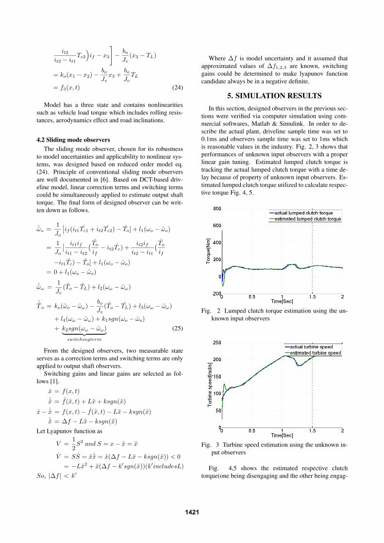
5. SIMULATION RESULTSIn this section, designed observers in the previous sec-
tions were verified via computer simulation using com-mercial softwares, Matlab & Simulink. In order to de-scribe the actual plant, driveline sample time was set to0.1ms and observers sample time was set to 1ms whichis reasonable values in the industry. Fig. 2, 3 shows thatperformances of unknown input observers with a properlinear gain tuning. Estimated lumped clutch torque istracking the actual lumped clutch torque with a time de-lay because of property of unknown input observers. Es-timated lumped clutch torque utilized to calculate respec-tive torque Fig. 4, 5.
Fig. 2 Lumped clutch torque estimation using the un-known input observers
Fig. 3 Turbine speed estimation using the unknown in-put observers
Fig. 4,5 shows the estimated respective clutchtorque(one being disengaging and the other being engag-
1421
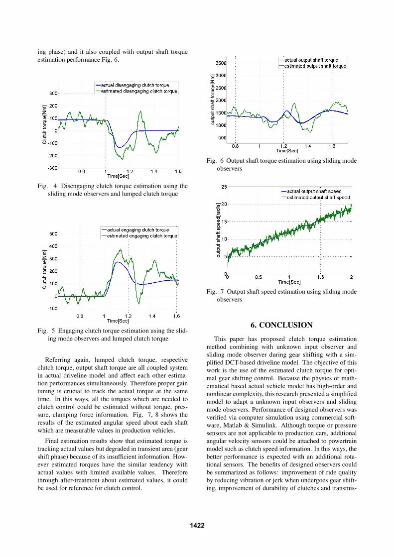
ing phase) and it also coupled with output shaft torqueestimation performance Fig. 6.
Fig. 4 Disengaging clutch torque estimation using thesliding mode observers and lumped clutch torque
Fig. 5 Engaging clutch torque estimation using the slid-ing mode observers and lumped clutch torque
Referring again, lumped clutch torque, respectiveclutch torque, output shaft torque are all coupled systemin actual driveline model and affect each other estima-tion performances simultaneously. Therefore proper gaintuning is crucial to track the actual torque at the sametime. In this ways, all the torques which are needed toclutch control could be estimated without torque, pres-sure, clamping force information. Fig. 7, 8 shows theresults of the estimated angular speed about each shaftwhich are measurable values in production vehicles.
Final estimation results show that estimated torque istracking actual values but degraded in transient area (gearshift phase) because of its insufficient information. How-ever estimated torques have the similar tendency withactual values with limited available values. Thereforethrough after-treatment about estimated values, it couldbe used for reference for clutch control.
Fig. 6 Output shaft torque estimation using sliding modeobservers
Fig. 7 Output shaft speed estimation using sliding modeobservers
6. CONCLUSION
This paper has proposed clutch torque estimationmethod combining with unknown input observer andsliding mode observer during gear shifting with a sim-plified DCT-based driveline model. The objective of thiswork is the use of the estimated clutch torque for opti-mal gear shifting control. Because the physics or math-ematical based actual vehicle model has high-order andnonlinear complexity, this research presented a simplifiedmodel to adapt a unknown input observers and slidingmode observers. Performance of designed observers wasverified via computer simulation using commercial soft-ware, Matlab & Simulink. Although torque or pressuresensors are not applicable to production cars, additionalangular velocity sensors could be attached to powertrainmodel such as clutch speed information. In this ways, thebetter performance is expected with an additional rota-tional sensors. The benefits of designed observers couldbe summarized as follows: improvement of ride qualityby reducing vibration or jerk when undergoes gear shift-ing, improvement of durability of clutches and transmis-
1422
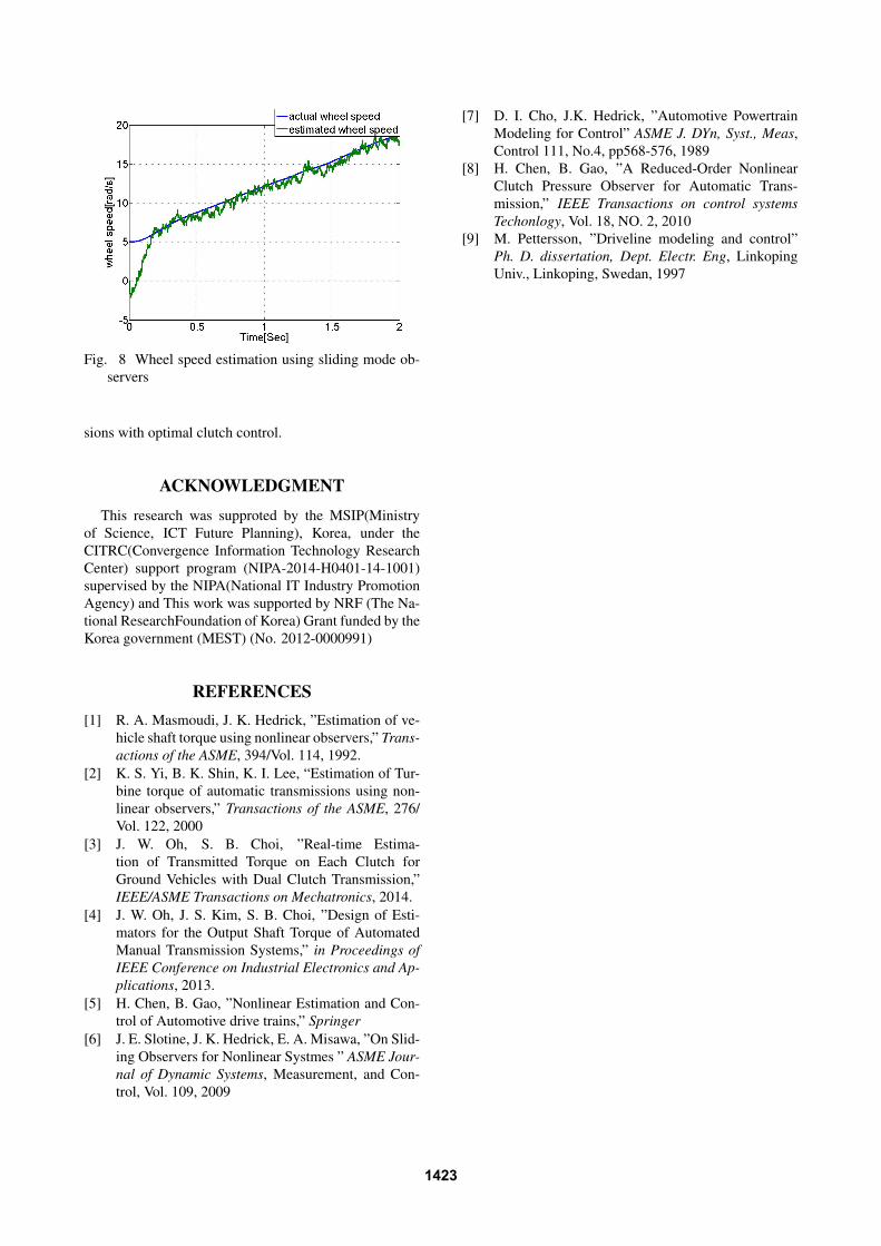
Fig. 8 Wheel speed estimation using sliding mode ob-servers
sions with optimal clutch control.
ACKNOWLEDGMENTThis research was supproted by the MSIP(Ministry
of Science, ICT Future Planning), Korea, under theCITRC(Convergence Information Technology ResearchCenter) support program (NIPA-2014-H0401-14-1001)supervised by the NIPA(National IT Industry PromotionAgency) and This work was supported by NRF (The Na-tional ResearchFoundation of Korea) Grant funded by theKorea government (MEST) (No. 2012-0000991)
REFERENCES[1] R. A. Masmoudi, J. K. Hedrick, ”Estimation of ve-
hicle shaft torque using nonlinear observers,” Trans-actions of the ASME, 394/Vol. 114, 1992.
[2] K. S. Yi, B. K. Shin, K. I. Lee, “Estimation of Tur-bine torque of automatic transmissions using non-linear observers,” Transactions of the ASME, 276/Vol. 122, 2000
[3] J. W. Oh, S. B. Choi, ”Real-time Estima-tion of Transmitted Torque on Each Clutch forGround Vehicles with Dual Clutch Transmission,”IEEE/ASME Transactions on Mechatronics, 2014.
[4] J. W. Oh, J. S. Kim, S. B. Choi, ”Design of Esti-mators for the Output Shaft Torque of AutomatedManual Transmission Systems,” in Proceedings ofIEEE Conference on Industrial Electronics and Ap-plications, 2013.
[5] H. Chen, B. Gao, ”Nonlinear Estimation and Con-trol of Automotive drive trains,” Springer
[6] J. E. Slotine, J. K. Hedrick, E. A. Misawa, ”On Slid-ing Observers for Nonlinear Systmes ” ASME Jour-nal of Dynamic Systems, Measurement, and Con-trol, Vol. 109, 2009
[7] D. I. Cho, J.K. Hedrick, ”Automotive PowertrainModeling for Control” ASME J. DYn, Syst., Meas,Control 111, No.4, pp568-576, 1989
[8] H. Chen, B. Gao, ”A Reduced-Order NonlinearClutch Pressure Observer for Automatic Trans-mission,” IEEE Transactions on control systemsTechonlogy, Vol. 18, NO. 2, 2010
[9] M. Pettersson, ”Driveline modeling and control”Ph. D. dissertation, Dept. Electr. Eng, LinkopingUniv., Linkoping, Swedan, 1997
1423