
TSUBAKI CAM CLUTCH BS-F SERIES · PDF fileTSUBAKI CAM CLUTCH BS-F SERIES ... TSUBAKI original...
12
One-way clutch NEW TSUBAKI CAM CLUTCH BS-F SERIES BACKSTOP Cam Clutch BACKSTOP Cam Clutch
Transcript of TSUBAKI CAM CLUTCH BS-F SERIES · PDF fileTSUBAKI CAM CLUTCH BS-F SERIES ... TSUBAKI original...

One-way clutch
NEW
TSUBAKICAM CLUTCHBS-F SERIESBACKSTOP Cam ClutchBACKSTOP Cam Clutch

Special labyrinth seal mechanism for dusty environment
The narrowest width with I-beam structure makes easy
installation for customer’s current layout
Special double lip oil seal and multi temperature grease
for wide temperature range
Developing new tec
TSUBAKI abundant B
Ideal for tough environment
Flexible labyrinth(Patent pending : JP)
Grease only(Grease fitting)
TSUBAKI BS-F(Flexible labyrinth)
Others(Grease fitting)
Flexible labyrinth blocked dust and water against cement and mining tough condition.
Sealing performance test by cement powder
Ambient temperature range
-40°C to +65°C(-40°F to +149°F)
Drop in design
No need to modify a current layout when a customer replaces the BACKSTOP.
New conveyor system also has a benefit to save the space and reduce the installation time.
1
2
1
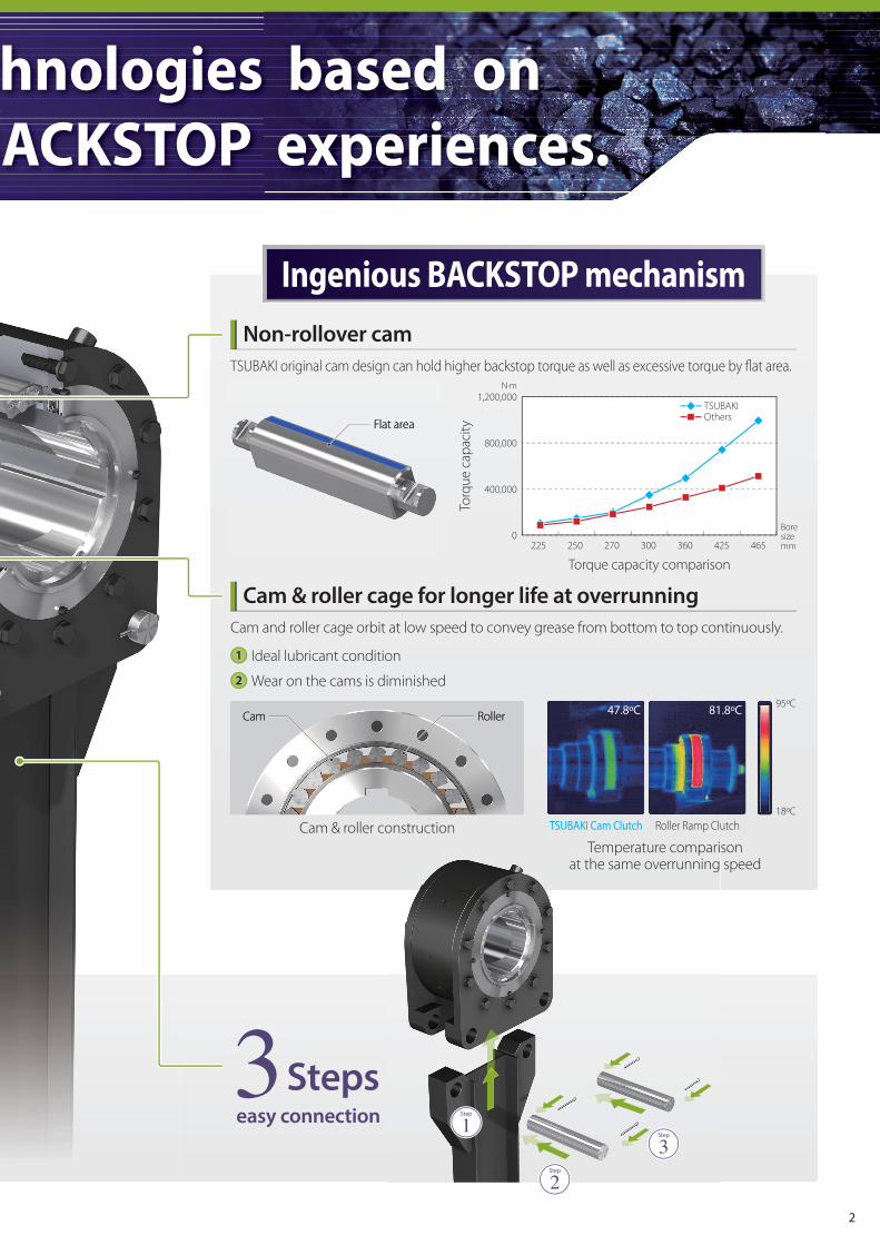
Non-rollover cam
Cam & roller cage for longer life at overrunning
hnologies based on
ACKSTOP experiences.
Flat areaFlat area
RollerRollerCamCam
TSUBAKI Cam Clutch Roller Ramp Clutch
Ideal lubricant condition
Wear on the cams is diminished
Ingenious BACKSTOP mechanism
TSUBAKI original cam design can hold higher backstop torque as well as excessive torque by flat area.
Cam and roller cage orbit at low speed to convey grease from bottom to top continuously.
Torque capacity comparison
Torq
ue
cap
acit
y
Cam & roller construction
Temperature comparisonat the same overrunning speed
1
2
1,200,000
800,000
400,000
0225 250 270 300 360 425 465
81.8ºC47.8ºC 95ºC
18ºC
3Stepseasy connection 1Step
2Step
3Step
N·m
Boresizemm
TSUBAKIOthers
2

Over runing speed comparison Width of inner race comparison
Ove
r ru
nin
g s
pee
d
Wid
th o
f in
ner
rac
e
High speed and Down sizing
Variety of options to satisfy customer demands
Safety cover
Prevent physical injury at operation as well as
dust and water from outside
1
Clutch Mounting Accessories3
400
300
200
100
0140 165 200 225 250 270 300 360 425 465
400
300
200
100
095 115 140 165 200 225 250 270 300
dust and water from outside
Oil lubrication
Easy maintenance
Oil level and condition monitoring
2
Shaft collar End plate Shaft key
TSUBAKI BACKSTOP BS-F series can meet the high speed trend of inclined conveyors as well as reducing width with our
new improved design.
It is easy replacement from customer’s current BACKSTOP.
r/min mm
Boresizemm
Boresizemm
TSUBAKIOthers
TSUBAKIOthers
For details, please contact TSUBAKI.
3

Preventing reverse rotation of inclined or vertical conveyor systems is one of the most common applications for BACKSTOPS.
There are many configurations of conveyors systems that employ BACKSTOPS.
This paper presents the most common types and provides examples and calculations needed to properly size BACKSTOP in
order to maximize performance and improve safety of the conveying system.
*Suggested arrangement may not meet local design standards, please check local design standards.
BACKSTOP Mounting Arrangements
Mounting arrangement
Figure 1 Figure 2
Figure 3
Single and Dual Drives
BACKSTOPS for low speed overrunning type are installed directly on the extended head shaft, as shown in Figure 1 and 2.
TSUBAKI recommends the single installation of the BACKSTOP to prevent the reverse rotation of head shaft.
Tandem Drives
When the conveyor arrangement calls for a primary and secondary drive, as shown in Figure 3, the BACKSTOP on the
primary drive unit holds the full load. The BACKSTOP on the secondary drive unit holds the back tension from the belt.
It keeps belt traction on both conveyor systems.
TSUBAKI recommends that the BACKSTOP, having the torque capacity equal to the sum of the primary and secondary
motors, be installed on the primary drive unit.
The BACKSTOP for secondary drive should be sized from secondary drive motor only.
*Suggested arrangement may not meet local design standards, please check local design standards.
Motor SpeedReducer
Belt ConveyorBACKSTOP BS-F
TorqueArm
Motor SpeedReducer
Belt ConveyorBACKSTOP BS-F
MotorSpeedReducer
Motor Speed Reducer
Belt ConveyorBACKSTOP BS-F
PRIMARY
Motor Speed Reducer
BACKSTOP BS-F
SECONDARY
4

A backstop by definition are required to hold back a load from moving in a reverse direction.
Care must be taken in calculating the torque requirements and should be based on maximum or worst case conditions and
not average/normal loads.
Because any failure of BACKSTOP might result in costly damage or injury, care must be exercised to consider all the possible
loads and select appropriate service factors.
The BACKSTOP needs to be sized for the breakdown or stalled torque of the drive motors.
The following table shows typical service factors to be applied when size selecting BACKSTOPS.
BACKSTOP Size Selection
Selection procedures by motor stall torque
175%
200%
250%
300%
1.30
1.30
1.67
2.00
Maximum Stalled Torque or Breakdown
torque % of Normal Motor RatingService Factor
Motor Stalled Torque = Motor maximum torque experienced with no shaft rotation
Service Factor
The BACKSTOP has no backlash, two BACKSTOPS can share the total calculated torque 50%/50% theoretically.
However, we have to consider “Load sharing factor” because Load sharing of BACKSTOPS on conveyors with multiple drives
is a key factor.
For proper load sharing the torque arm gap clearance should be reduced to a zero gap, thus no swing of the torque arm
before the cams in both BACKSTOPS prevent the inner race from rolling back.
Dual Drive Application
For dual drive to a single head shaft, if the required backstop capacity is in excess of the listed capacity in the catalogue,
a twin arrangement of BACKSTOP Cam Clutch is the solution, as shown in Figure 4.
And we have to consider “Load sharing factor”.
Load sharing
In this arrangement, load sharing factor becomes 1.7 for two BACKSTOP Cam Clutches
Required torque for selection = Motor nominal torque × Service Factor
Belt ConveyorBACKSTOP BS-FBACKSTOP BS-F
MotorSpeed ReducerMotor Speed Reducer
Figure 4
5

INFORMATION FOR SELECTION
Selection procedures by backstop torque
Note:
For the conveyor types other than those in the above examples, calculate the backstop torque accordingly.
Always allow for the maximum possible load in your calculations, since backstopping often occurs when the conveyor is
loaded above its normal loading capacity.
Selection procedures for bucket elevator
Determine the mode of operation
Refer to the selection procedure corresponding to the mode of operation
For Belt Conveyors (Short inclined yard conveyors)
Selection Procedure:
Selection Procedure 1
2
1. Calculate the power to move an empty belt and idlers: (P1)
P1 = 0.06 × f × W × V × 367
(kW)
2. Calculate the power to move a loaded belt horizontally: (P2)
P2 = f × Qt × 367
(kW)
ℓ + ℓ0
ℓ + ℓ0
3. Calculate the power to move the load vertically: (P3)
P3 = 367
(kW)h × Qt
5. Calculate the back stop torque: (T)
T = N
× SF (N·m)9550 × Pr
6. Select the proper clutch which satisfies the calculated backstop torque.
4. Calculate the back stop power: (Pr)
Pr = P3 – 0.7(P1 + P2) (kW)
Motor Speed Reducer
Bucket
Chain andSprocket
BACKSTOP BS-F
Torque Arm
MotorSpeed Reducer
Belt ConveyorBACKSTOP BS-F
TorqueArm
1.5
2.0
Several times a day
More than several times a day
SF Service condition
Use the values from the table below.
Note:
L
D
Qt
V
SF
= Total lift (m)
= Pitch circle dia. of head sprocket (m)
= Possible maximum load (tons/hour)
= Velocity of conveyor (m/min)
= Service factor
1.5
2.0
Backstopping: Several times a day
Backstopping: More than several times a day
SF Service condition
Select service factor from table below:
Width of Belt (mm)
Estimated Weight: W
400
22.4
450
28
500
30
600
35.5
750
53
900
63
Width of Belt (mm)
Estimated Weight: W
1,050
80
1,200
90
1,400
112
1,600
125
1,800
150
2,000
160
Use the values from the table below.
Note:
f
W
= Friction coefficient of rollers
= 0.03 (normally used)
= Weight of moving parts of the conveyor in the unloaded
condition (kg/m)
V
Qt
h
ℓ
ℓ0
N
SF
= Velocity of conveyor (m/min)
= Max. possible load (tonnes/hour)
= Total lift (m)
= Horizontal distance between head pulley and tail pulley (m)
= Modification coefficient for ℓ
= 49 m (normally used)
= Shaft speed (r/min) on which the clutch is mounted.
= Service factor
For Bucket Elevators
Selection Procedure:
1.T =
120 × V × SF (N·m)
2.
(L + D) × Qt × D × 9800
Select the correct clutch which satisfies the calculated backstop torque (T).
6
B/2
V
X
LK
J
Z
YO
GG
F
E
D
C
B
AH
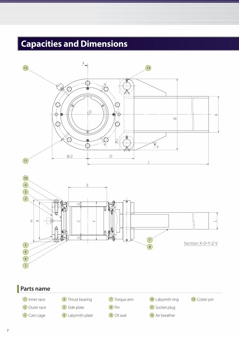
Capacities and Dimensions
12 13
10
8
4
1
11
7
6
9
5
3
2
Inner race
Outer race
Cam cage
1
2
3
Thrust bearing
Side plate
Labyrinth plate
4
5
6
Torque arm
Pin
Oil seal
7
8
9
Labyrinth ring
Socket plug
Air breather
10
11
12
Cotter pin13
Parts name
Section X-O-Y-Z-V
7

SizeTorque
capacity(N·m)
Max. Overrunning
speed(r/min)
Bore range(mm)
Drag torque(N·m)
Mass(kg) Amount of
grease(kg)Within Torque arm Without Torque arm
Inner race Min. Max. Min.bore Max.bore Min.bore Max.bore
BS85F 6,760 300 60 85 8 43 40 31 28 0.065
BS95F 8,940 300 70 95 10 52 48 37 34 0.075
BS115F 16,300 300 80 115 15 82 76 59 53 0.105
BS140F 24,400 300 90 140 20 114 104 84 74 0.15
BS165F 44,100 300 100 165 34 174 159 118 103 0.16
BS200F 61,700 180 100 200 44 263 235 185 157 0.19
BS225F 102,000 150 150 225 74 489 439 386 336 1.3
BS250F 147,000 135 175 250 93 692 635 556 499 1.4
BS270F 192,000 125 200 270 98 889 828 692 631 1.6
BS300F 345,000 115 230 300 108 1,300 1,230 1,050 973 1.8
BS360F 489,000 100 250 360 157 1,870 1,750 1,580 1,460 1.9
BS425F 735,000 85 325 425 216 3,080 2,890 2,610 2,420 3.5
BS465F 980,000 80 350 465 245 3,770 3,510 3,160 2,900 4.4
Size A B C D E F G H * J * K * L
BS85F 107 210 105 151 106 120 7.5 127 813 76 64
BS95F 107 230 112 161 120 120 4 127 914 102 71
BS115F 127 270 127 181 142 135 4 149 1,270 102 71
BS140F 127 320 134 207.5 170 142 4 151 1,422 127 76
BS165F 141 360 134 242.5 209 142 4 169 1,676 152 91
BS200F 150 430 142 284 251 150 4 178 1,829 203 106
BS225F 257 500 203 325 270 268 32.5 293 1,981 254 118
BS250F 247 600 229 385 300 272 21.5 283 2,083 305 127
BS270F 267 650 254 415 344 280 13 303 2,235 305 140
BS300F 278 780 273 490 430 286 6.5 320 2,388 381 143
BS360F 292 930 278 585 490 286 4 345 2,540 457 152
BS425F 380 1,030 396 645 600 404 4 433 2,743 508 162
BS465F 410 1,090 417 690 600 432 7.5 474 3,048 610 184
All dimensions are in mm.
Capacities
Dimensions
Model name
BS 300 F – 280 J
Model name
BS : BACKSTOP
300 : Size
F : F series
Bore size in mm
280 : 280mm H7
Keyway
J : JIS B1301-1996, ISO R773
Notes: Torque arm dimensions are imperial base. Please contact TSUBAKI for metric torque arm dimensions.
8

Installation and UsageRecommended shaft tolerance is h7 or h8.1
Before installation, verify that the direction of the rotation of the inner race of the BS-F Cam Clutch (shown by the arrow
on the end face of the inner race) is the same as the direction of the rotation of the conveyor.
2
Securely install the torque arm to the BS-F Cam Clutch using furnished torque arm pins and cotter pins.3
Apply pressure only on the end face of the inner race when inserting the BS-F Cam Clutch on to the shaft.
Do not hit the inner race directly with a hammer or apply pressure on the side plate, labyrinth plate, or bolts.
4
Always use a parallel key for installation onto the shaft and then fix the BS-F Cam Clutch to the shaft with the end plate.
Never use a tapered key, otherwise the Cam Clutch will be damaged.
5
The end tip of the torque arm will swing to some extent while the conveyor is operating.
Support the torque arm end tip only in the direction of rotation, but be sure to allow it a certain amount of free
movement axially. (See illustration below.)
The Cam Clutch will sustain damage if the torque arm end tip is fixed securely.
6
For details, see the manual supplied with the product.
Never use a
tapered key.
Always use a
parallel key.
Use the end plate to fix the
cam clutch onto the shaft.
Apply pressure only to the
inner race when fitting onto
the shaft.Total clearance should be
between 2 to 5 mm.
9

Series Lubricant Maintenance
BS-F 85 to 465 GreasePre-lubricated with grease.
Drain and clean inside of the Backstop and inject new grease, minimum once a year.
Maintenance Instructions
Recommended Grease
Brand BS-F Series
Exxon Mobil Beacon 325
1. Do not use grease that contains EP additives.
2. The ambient operating temperature range of the grease listed above is -40°C (-40°F) and +65°C (+149°F).
Please consult Tsubaki if operating outside of this range.
3. Beacon 325 is available from Tsubaki and is NOT able to be mixed with other greases.
Notes:
Safety Guide
Warranty:Tsubaki E&M Co.: hereinafter referred to as "Seller" Customer: hereinafter referred to as "Buyer"Goods sold or supplied by Seller to Buyer: hereinafter referred to as "Goods"
WARNING
1. Warranty period without charge 3. Warranty with charge
4. Dispatch service
2. Warranty coverage
CAUTIONThis mark indicates a situation where incorrect handling may cause hazardous conditions, resulting in death or severe injury.
This mark indicates a situation where incorrect handling may cause hazardous conditions, resulting in medium or slight personal injury or property damage.
Guards must be provided on all power transmission and conveyor applications in accordance with provisions of
ANSI/ASME B 15.1 1992 and ANSI/ASME B 20.1 1993 or other applicable standards. When revisions of these standards are
published, the updated edition shall apply.
When using any of the products described in this catalog, be sure to follow any applicable safety laws and regulations
(such as the Labor Safety and Health Regulations).
Follow the instructions below when installing, maintaining, or inspecting a product.
1. Turn the power switch off.
2. Do not store the device under equipment that may fall.
3. Secure the movable parts of the equipment so as not to move.
4. Wear clothing and protective gear suitable for the work.
When performing a test operation or during periodic inspections, verify that the protective equipment is functioning
properly.
Always lock out power switch before installing, removing, lubricating or servicing a system that uses Cam Clutch
products.
If the Cam Clutch is used for repeated starting and stopping, make sure the strength of the supports for the Cam Clutch
are sufficient.
The capacity of your Cam Clutch may be effected by the accuracy of its set up, the amount of pressure exerted on it,
wear on other parts in your system, or wear life of the Cam Clutch itself. Check the Cam Clutch at regular intervals and
take any necessary safety precautions.
When connecting or disconnecting Cam Clutch products, eye protection is required. Wear safety glasses, protective
clothing, gloves and safety shoes.
Cam Clutch maintenance and inspection should be performed only by qualified personnel with specialized knowledge.
Otherwise, fire, and injury may occur.
Operate the Cam Clutch according to the manufacturer’s instructions.
Effective 18 months from the date of shipment or 12 months from the first use of Goods,
including the installation of the Goods to the Buyer's equipment or machine - whichever comes
first.
Seller will charge for any investigation and repair of Goods caused by:
1) Improper installation by failing to follow the instruction manual.
2) Insufficient maintenance or improper operation by the Buyer.
3) Incorrect installation of the Goods to other equipment or machines.
4) Any modifications or alterations of Goods by the Buyer.
5) Any repair by engineers other than the Seller or those designated by the Seller.
6) Operation in an environment not specified in the manual.
7) Force Majeure or forces beyond the Seller's control such as natural disasters and
injustices inflicted by a third party.
8) Secondary damage or problems incurred by the Buyer's equipment or machines.
9) Defective parts supplied or specified by the Buyer.
10) Incorrect wiring or parameter settings by the Buyer.
11) The end of life cycle of the Goods under normal usage.
12) Losses or damages not liable to the Seller.
The service to dispatch a Seller's engineer to investigate, adjust or trial test the Seller's Goods
is at the Buyer's expense.
Should any damage or problem with the Goods arise within the warranty period, given that the
Goods were operated and maintained according to the instructions provided in the manual,
the Seller will repair and replace at no charge once the Goods are returned to the Seller.
This warranty does not include the following:
1) Any costs related to removal of Goods from the Buyer's equipment or machine to repair or
replace parts.
2) Cost to transport Buyer's equipment or machines to the Buyer's repair shop.
3) Costs to reimburse any profit loss due to any repair or damage and consequential losses
caused by the Buyer.
Ensure that the end user of the device receives the appropriate
instruction manual.
Also make sure that the contents of the manual are carefully read
before use.
In the event that an instruction manual is not available, use the
device name and model number to request one from the
distributor where you purchased the device or from our sales
office.
Do not rearrange the device’s components or perform additional
work in order to modify the device in any way.
Periodically check the product’s functions and operations
according to the instruction manual. If a function or operation is
found to be inadequate, contact the distributor for repair.
When disposing of the device, treat it as industrial waste.
The device detai ls descr ibed in this catalog are intended
primarily for model selection. Before using the device, read the
instruction manual thoroughly, and ensure the device is used
correctly.
The logos and product names used in this catalog are either trademarks or registered trademarks of
Tsubakimoto Chain Co. or the Tsubaki Group in Japan and other countries.
Lubrication and Maintenance
10

INDIAN OCEAN RIM
Singapore Tsubakimoto Singapore Pte. Ltd. +65 6861-0422/3/4 http://tsubaki.sg/
Australia Tsubaki Australia Pty. Limited +61 2-9704-2500 http://tsubaki.com.au/
India Tsubaki India Power Transmission Private Limited +91 73580-80060 http://tsubaki.in/
Indonesia PT. Tsubaki Indonesia Trading +62 21-571-4230/1 http://tsubakimoto.co.id/
Malaysia Tsubaki Power Transmission (Malaysia) Sdn. Bhd. +60 3-7859-8585 http://tsubaki.my/
New Zealand Tsubaki Australia Pty. Limited - New Zealand Branch +64 9 352-2085 http://tsubaki.com.au/
Philippines Tsubakimoto Philippines Corporation +63 2-808-0067 http://tsubaki.ph/
Thailand Tsubakimoto (Thailand) Co., Ltd. +66 2-262-0667/9 http://tsubaki.co.th/
Vietnam Tsubakimoto Vietnam Co., Ltd. +84 4-6274-1449 http://tsubaki.net.vn/
EAST ASIA
Korea Tsubakimoto Korea Co., Ltd. +82 2-2183-0311 http://tsubakimoto-tck.co.kr/
Taiwan Taiwan Tsubakimoto Co. +886 33-293827/8/9 http://tsubakimoto.com.tw/
CHINA
China Tsubakimoto Chain (Shanghai) Co., Ltd. +86 215396-6651/2 http://tsubaki.cn/
EUROPE
Netherlands Tsubakimoto Europe B.V. +31 78-6204000 http://tsubaki.eu/
France Kabelschlepp France S.A.R.L. +33 1-34846365 http://kabelschlepp.fr/
Germany Tsubaki Deutschland GmbH +49 8105-7307100 http://tsubaki.de/
Tsubaki Kabelschlepp GmbH +49 2762-4003-0 http://kabelschlepp.de/
Italy Kabelschlepp Italia S.R.L. +39 0331-350962 http://kabelschlepp.it/
Russia OOO Tsubaki Kabelschlepp +7 499-4180212 http://kabelschlepp.ru/
Spain Tsubaki Ibérica Power Transmission S.L. +34 911-873450 http://tsubaki.es/
United Kingdom Tsubakimoto U.K. Ltd. +44 1623-688-700 http://tsubaki.eu/
AMERICAS
United States of America U.S. Tsubaki Power Transmission, LLC +1 847-459-9500 http://www.ustsubaki.com/
Brazil Tsubaki Brasil Equipamentos Industriais Ltda. +55 11-3253-5656 http://tsubaki.ind.br/
Canada Tsubaki of Canada Limited +1 905-676-0400 http://tsubaki.ca/
Japan Headquarters +81 6-6441-0011 http://tsubakimoto.com
Global Group Companies
TSUBAKIMOTO CHAIN CO.
Note: In accordance with the policy of TSUBAKIMOTO CHAIN CO. to constantly improve its products, the specifications in this catalog are subject to change without notice.
The logos, brand names, or product names in this catalog are trademarks or registered trademarks of Tsubakimoto Chain Co. and its subsidiaries in Japan, US and other countries.
Catalog No.985K558 ©2017/2 TSUBAKIMOTO CHAIN CO. Printed in Japan (K) 1,000
The Tsubaki Eco Link logo is used only on products
that satisfy the standards for environmental friendliness set by the Tsubaki Group.