ESPRIT Milling Tutorial 01
24
Project 2: Mill a Standard Part | 61 P R O J E C T Mill a Standard Part ESPRIT has very strong capabilies in 2.5D milling, providing both ease-of-use and a high level of control over every aspect of a milling operaon. The intent of this project is to teach you the process for creang standard milling operaons using ESPRIT’s SolidMill Tradional machining technology. ESPRIT gives you several opons for accessing standard milling commands. Menus and Toolbars. • Tradional milling commands are located on the SolidMill Tradional submenu on the Machining menu. You can also use the SolidMill toolbar. Process Manager. • You can also select SolidMill commands from a single menu within the Process Manager. The Process Manager lets you apply several machining operaons to a single feature at one me. For this project, you will learn how to use the commands on the SolidMill Tradional toolbar to create standard milling operaons and how to create a machining process using the Process Manager. 2 Remove Excess Material ........... 62 Cut the Pockets and Slot ......... 70 Mill and Drill Holes....................... 77 Create a Shop Floor Report ... 82 The files for this project are available for download from ESPRITWeb » File Library » ESPRIT 2009 and from the ESPRIT CD. All dimensions in this tutorial are in millimeters. Make sure System Unit on the Tools menu is set to Metric. Before you start this lesson, you can review and simulate the cung operaons in the following file: Milling - Standard\standard_milling_complete.esp.
-
Upload
sandaruwan- -
Category
Documents
-
view
1.512 -
download
71
Transcript of ESPRIT Milling Tutorial 01
Project 2: Mill a Standard Part | 61
PRO
JECT
Mill a Standard Part
ESPRIT has very strong capabili�es in 2.5D milling, providing
both ease-of-use and a high level of control over every
aspect of a milling opera�on.
The intent of this project is to teach you the process for
crea�ng standard milling opera�ons using ESPRIT’s SolidMill
Tradi�onal machining technology.
ESPRIT gives you several op�ons for accessing standard
milling commands.
Menus and Toolbars. • Tradi�onal milling commands are
located on the SolidMill Tradi�onal submenu on the
Machining menu. You can also use the SolidMill toolbar.
Process Manager. • You can also select SolidMill commands
from a single menu within the Process Manager. The
Process Manager lets you apply several machining
opera�ons to a single feature at one �me.
For this project, you will learn how to use the commands on
the SolidMill Tradi�onal toolbar to create standard milling
opera�ons and how to create a machining process using the
Process Manager.
2
Remove Excess Material ........... 62
Cut the Pockets and Slot ......... 70
Mill and Drill Holes .......................77
Create a Shop Floor Report ... 82
The files for this project are available for download from
ESPRITWeb » File Library » ESPRIT 2009 and from the ESPRIT
CD.
All dimensions in this tutorial are in millimeters. Make sure
System Unit on the Tools menu is set to Metric.
Before you start this lesson, you can review and simulate the
cu"ng opera�ons in the following file:
Milling - Standard\standard_milling_complete.esp.
62 | Get Started with ESPRIT 2009
Remove Excess MaterialAt the beginning of any milling job, it is cri�cal
to remove as much excess stock as possible
before you begin cu"ng the finish passes.
In this project, the part is cut from standard
rectangular stock. The first thing you need to
do is remove the excess material from the top
and around the sides of the part.
To do this, you will first create a facing
opera�on to quickly remove as much stock as
possible from the top of the part. Then you
will create a 3D contour around the island on
the top face. You will finish by roughing and
finishing the outer profile of the part.
Facing
The Facing command is ESPRIT has mul�ple
op�ons to make facing as fast and effec�ve as
possible. You have full control over depths of
cut, op�mized cu"ng angle, stock allowance on
floors and walls, and how far you want the tool
to travel when it reaches the edge of the stock.
The Facing opera�on also automa�cally creates
a final pass around any islands. This guarantees
a consistent amount of stock on floors and
walls.
Wire Frame Mill ing
The Wire Frame Milling command lets you
create a basic 3D milling opera�on from simple
2D geometry. The profile of the shape you want
to cut is called the drive curve. This profile is
driven along a path called the basic curve. Each
curve must be created on a separate plane
and the end point of the drive curve must
lie along the basic curve. When construc�ng
the tool path, the drive curve will be placed
perpendicular to the basic curve at the start
point of the basic curve.
Contouring
The Contouring command creates cu"ng
passes that follow the shape of a selected
feature. You can center the tool on the feature
or offset it to the le% or the right. You can enter
an offset distance or use the radius of the tool.
The Contouring command lets you combine
rough and finish passes in a single opera�on
or you can create separate rough and finish
passes. When roughing and finishing passes
are combined in one Contouring opera�on,
the same tool is used for both phases of the
opera�on. To use different tools, you must
create separate contouring opera�ons.
It is recommended that you use separate
opera�ons for roughing and finishing.
Technology Files
Machining technology se"ngs can be easily
saved as a separate file and used over and
over for the machining of similar parts. For this
project, you will load pre-exis�ng technology
files that are located in the following folder:
Ge"ng Started\Milling - Standard\Technology
A%er loading the technology for an opera�on,
you can click on the various tabs to review
the individual se"ngs. For more detailed
informa�on, click the Help bu&on located at
the lower right corner of the technology page.
Project 2: Mill a Standard Part | 63
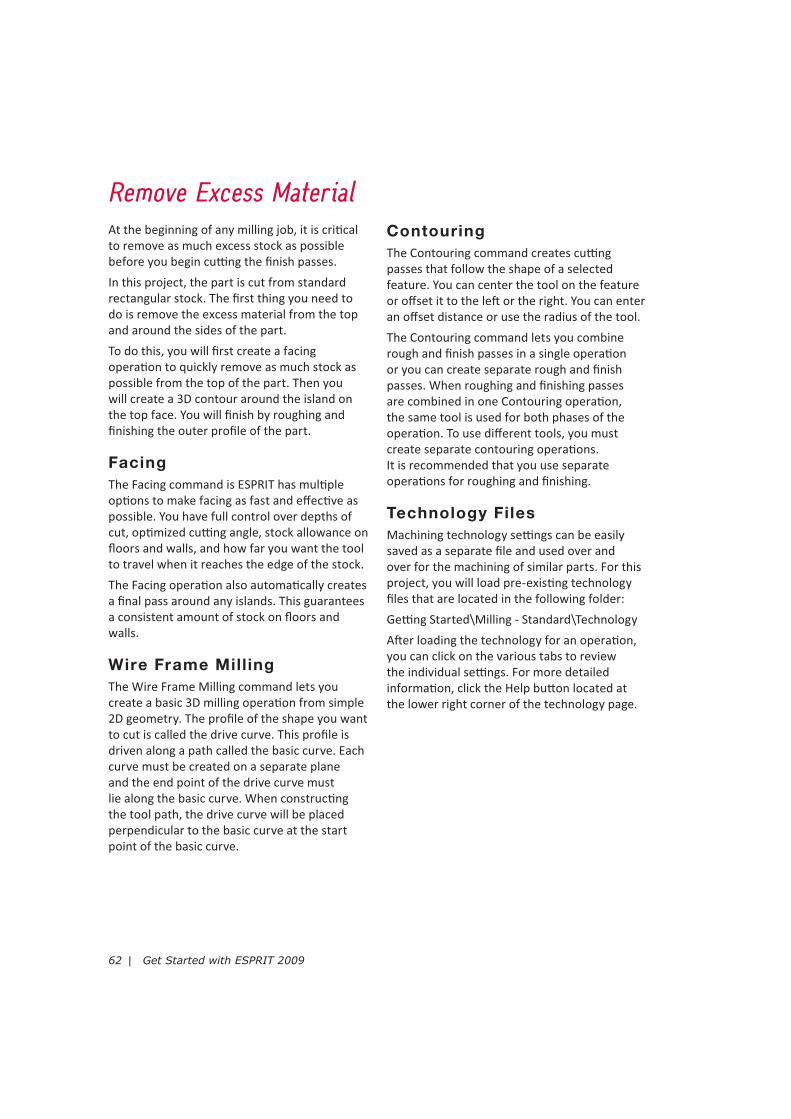
Open the Part File
Make sure 1. HI mode is enabled.
Locate and open the following file: Milling - Standard\2. standard_milling.esp
On the 3. Smart toolbar, click SolidMill Tradi�onal - SolidMill Produc�on to display the toolbar.
If you completed Project 1: Create Features, these milled features should look familiar to you.
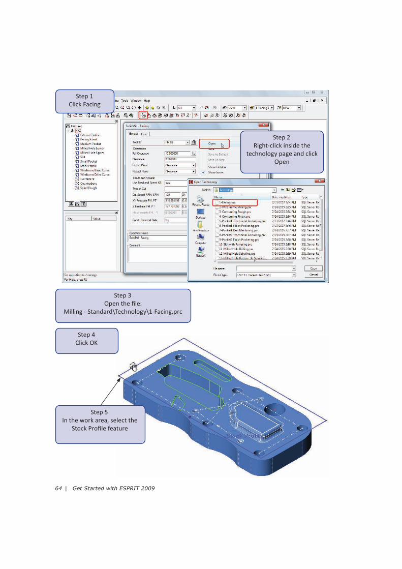
Create a Facing Operation
For this facing opera�on, there is an island on the face that must be avoided. The Facing
command lets you select and avoid islands and pocketed areas when the Include Islands op�on
is set to Yes.This opera�on will start slightly below the selected feature and cut at incremental
depths of 8mm in a simple back and forth tool mo�on. A stock allowance of 0.5mm will remain
on the walls of the island a%er the opera�on is complete. No stock allowance will remain on the
floors.
Typically, you would select the feature first and then define the opera�on technology. Because
there is an island on the face, you must first define the facing technology and select the Include
Islands op�on. ESPRIT will then prompt you to select features for the boundary, any islands and
any pockets you want to avoid. You will select the stock profile feature and the island profille.
You want to face across the tops of the pockets on this part, so you will simply answer No when
ESPRIT prompts you to select pockets to avoid.
64 | Get Started with ESPRIT 2009
Step 1
Click Facing
Step 2
Right-click inside the
technology page and click
Open
Step 4
Click OK
Step 3
Open the file:
Milling - Standard\Technology\1-Facing.prc
Step 5
In the work area, select the
Stock Profile feature
Project 2: Mill a Standard Part | 65
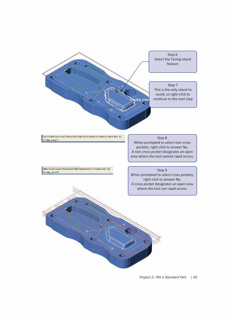
Step 6
Select the Facing Island
feature
Step 8
When prompted to select non-cross
pockets, right-click to answer No.
A non-cross pocket designates an open
area where the tool cannot rapid across.
Step 7
This is the only island to
avoid, so right-click to
con�nue to the next step
Step 9
When prompted to select cross pockets,
right-click to answer No.
A cross pocket designates an open area
where the tool can rapid across.

66 | Get Started with ESPRIT 2009
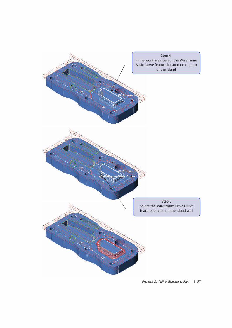
Create a Wire Frame Mill ing Operation
For this opera�on, you will use two exis�ng features. The Wireframe Drive Curve defines the
curved profile for the walls around the island on the face. The Wireframe Basic Curve feature is
located on the top face of the island and defines the path the profile will follow.
For Wire Frame Milling, you first define the machining technology and then select the features.
The Machine Along op�on controls which curve is used to control the direc�on of the cu"ng
passes. In this case, the tool will follow the direc�on of the basic curve.
Step 1
Click Wire Frame
Milling
Step 2
Open the file:
2-Wire Frame Milling.prc
Step 3
Click OK
Project 2: Mill a Standard Part | 67
Step 4
In the work area, select the Wireframe
Basic Curve feature located on the top
of the island
Step 5
Select the Wireframe Drive Curve
feature located on the island wall
68 | Get Started with ESPRIT 2009
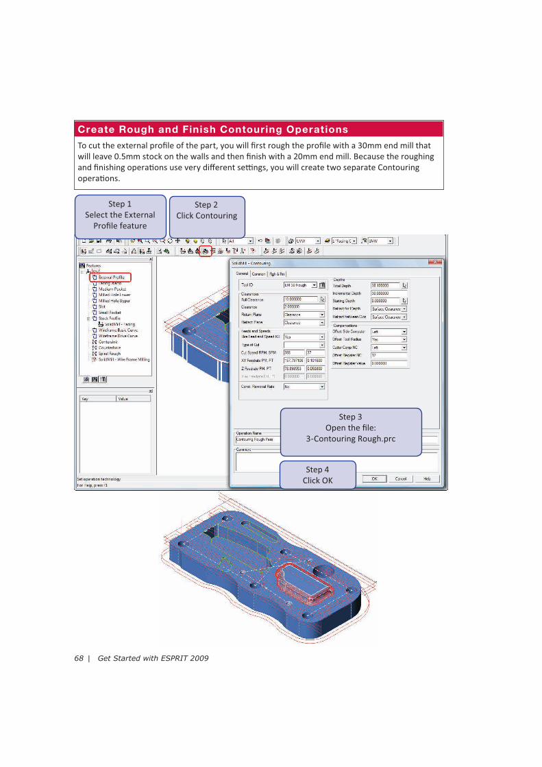
Create Rough and Finish Contouring Operations
To cut the external profile of the part, you will first rough the profile with a 30mm end mill that
will leave 0.5mm stock on the walls and then finish with a 20mm end mill. Because the roughing
and finishing opera�ons use very different se"ngs, you will create two separate Contouring
opera�ons.
Step 1
Select the External
Profile feature
Step 3
Open the file:
3-Contouring Rough.prc
Step 4
Click OK
Step 2
Click Contouring

Project 2: Mill a Standard Part | 69
Step 5
With the feature s�ll
selected, click Contouring
Step 6
Open the file:
4-Contouring Finish.prc
Step 7
Click OK
70 | Get Started with ESPRIT 2009
Cut the Pockets and SlotThe part in this project contains two pockets
and a slot. ESPRIT offers two types of pocke�ng
opera�ons that you will use to cut each pocket.
Trochoidal Pocketing
The Trochoidal Pocke�ng command is used
to quickly rough parts at a constant material
removal rate. Trochoidal Pocke�ng provides
mul�ple levels of control over tool mo�on
pa&ern, feedrates, and cu&er load.
Trochoid tool mo�on is well suited for high-
speed machining (HSM) because it uses the
biggest possible curve based on the shape of
the pocket, allowing for the fastest possible
feedrates. Although developed for high-
speed machining, Trochoidal Pocke�ng brings
benefits to any type of machine by providing a
more constant tool load and a be&er surface
finish.
The Trochoid tool mo�on pa&ern creates
a spiral in the largest area of the pocket to
maintain a constant level of tool loading. When
the trochoid pa&ern reaches the maximum
radius that will fit, the rest of the tool path
uses an adjustable curve that adapts to the
shape of the pocket.
Pocketing
The Pocke�ng command removes material
within a closed boundary. Within a single
pocke�ng opera�on, you have the op�on
to create separately definable phases for
roughing, wall finishing, and floor finishing
passes that each let you use a different tool.
For example, you can use a standard end mill
on the floors to provide the required finish and
use a ball or taper end mill on the walls. If you
do not want all of these phases combined in
a single opera�on, you can create each phase
independently. You can choose to create only
roughing passes, only wall finishing or floor
finishing passes, or a combina�on of your
choice. This gives you the flexibility to create
pocke�ng opera�ons with full control over the
process.
Rest Machining
The Rest Machining command is used to
remove material in areas and corners that
previous opera�ons le% behind. You can create
rest machining opera�ons for several parent
opera�ons at one �me or you can create
rest machining opera�ons for all opera�ons
associated with a single feature. The previous
opera�on becomes the “parent” opera�on
and the rest machining opera�on applied to
it becomes the “child” opera�on. The child
opera�on inherits many of the se"ngs from
the parent opera�on, such as total depth,
stock allowance, clearance se"ngs, and so
on. If a parent opera�on is modified, the
rest machining opera�on is automa�cally
recalculated and updated.
Machining Processes
A machining process is a convenient way to
create and apply several opera�ons at once.
The Process Manager lets you create any
number and type of machining opera�ons and
apply them to any number of features.
Important: To use the Process Manager,
your security key must be a&ached to your
computer and you must have a valid license. If
you are running ESPRIT in demo mode, use the
commands on the SolidMill Tradi�onal toolbar
to cut the pockets.

Project 2: Mill a Standard Part | 71
Set Up the KnowledgeBase
On the 1. Smart toolbar, click Common Machining and then click KnowledgeBase Document
Se!ngs.
Set 2. Part Type to Milled Part Std - Metric.
Set 3. Default Technology to Default Technology - Inch / Metric.
Click 4. OK.
Click 5. KnowlegeBase Se!ngs.
Make sure ‘6. Apply selected process to all features’ is checked and click OK.
Step 1
Select the Medium Pocket
feature and then click
Process Manager
Step 2
A process already exists in the
KnowledgeBase. Click New Process
to create your own process.
Step 3
Select SolidMill Tradi�onal -
Trochoidal Pocke�ng
Create a Process to Mil l the Medium Pocket
To mill the medium pocket, you will first remove as much material as possible as quickly as
possible with a Trochoidal Pocke�ng opera�on. A stock allowance of 0.5mm will remain on the
walls and floors of the pocket. A tradi�onal Pocke�ng opera�on will then be applied to first
finish the walls and then the floors. To remove any material remaining in the corners, you will
then apply a Rest Machining opera�on. You will create a machining process to perform all three
opera�ons.

72 | Get Started with ESPRIT 2009
Step 5
Select SolidMill Tradi�onal -
Tradi�onal Pocke�ng
Step 4
Open the file:
5-Pocket1 Trochoidal Pocke�ng.prc
and click OK
Step 6
Open the file:
6-Pocket1 Finish Pocke�ng.prc
and click OK

Project 2: Mill a Standard Part | 73
Step 7
Select SolidMill Tradi�onal -
Rest Machining
Step 8
Open the file:
7-Pocket1 Rest Machining.prc
and click OK
Step 9
Click Apply
Do not click Exit yet
74 | Get Started with ESPRIT 2009
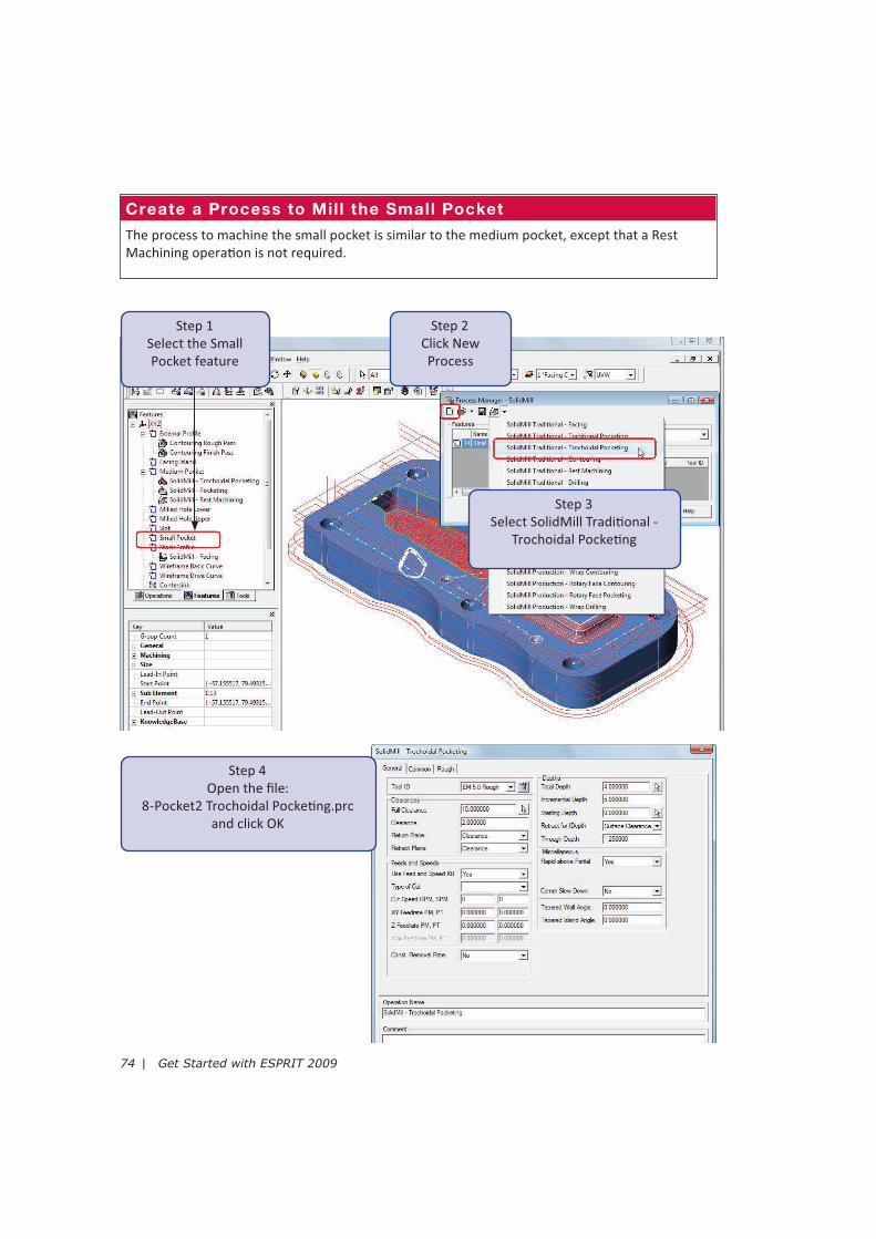
Create a Process to Mil l the Small Pocket
The process to machine the small pocket is similar to the medium pocket, except that a Rest
Machining opera�on is not required.
Step 1
Select the Small
Pocket feature
Step 2
Click New
Process
Step 3
Select SolidMill Tradi�onal -
Trochoidal Pocke�ng
Step 4
Open the file:
8-Pocket2 Trochoidal Pocke�ng.prc
and click OK
Project 2: Mill a Standard Part | 75
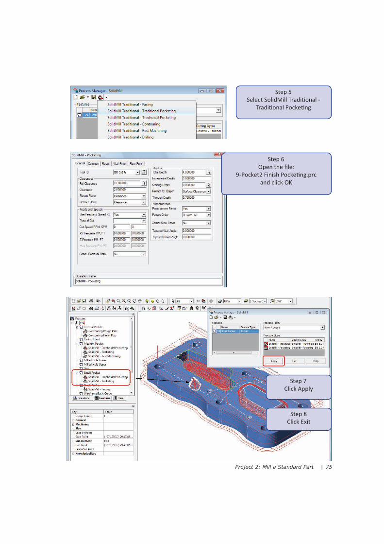
Step 5
Select SolidMill Tradi�onal -
Tradi�onal Pocke�ng
Step 7
Click Apply
Step 8
Click Exit
Step 6
Open the file:
9-Pocket2 Finish Pocke�ng.prc
and click OK
76 | Get Started with ESPRIT 2009
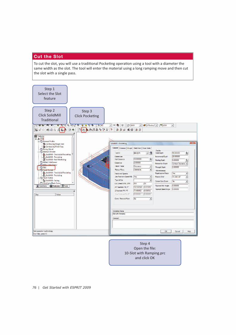
Cut the Slot
To cut the slot, you will use a tradi�onal Pocke�ng opera�on using a tool with a diameter the
same width as the slot. The tool will enter the material using a long ramping move and then cut
the slot with a single pass.
Step 1
Select the Slot
feature
Step 3
Click Pocke�ng
Step 4
Open the file:
10-Slot with Ramping.prc
and click OK
Step 2
Click SolidMill
Tradi�onal

Project 2: Mill a Standard Part | 77
Mill and Drill HolesThis part has different types of holes, including a milled hole. For this project, you will create
drilling and spiraling opera�ons depending on the type and size of the hole.
Drill ing
The Drilling command is applied to hole features or point-to-point (PTOP) features. The drilling
order is defined by the path of the PTOP feature. SolidMill Drilling supports several types of
drilling, including drill, tap, peck, and bore. The opera�on drills to a specified depth and you have
the op�on to include the length of the tool �p in the total depth value. You can also use SolidMill
Drilling to spot drill holes to the correct depth based on the diameter of the tool and the chamfer
diameter.
Spiraling
The Spiraling command creates spiral or helical cu"ng passes based on the selec�on of a circle
or a feature in the shape of a circle. A spiraling opera�on is typically used when you want to mill a
hole that is too large to drill.
Bottom Up Spiraling
Spiraling passes can be created from the top down or from the bo&om up. Bo&om up spiraling
can be used to avoid having to rotate your part using index milling. Bo&om up toolpath will be
automa�cally generated when the incremental depth is set to a nega�ve value.
When using bo&om up technology, the tool origin is very important. By default, all ESPRIT tools
have the origin set on the bo&om. The bo&om up technology does not shi% the tool origin, so you
have to be aware of the tool thickness when crea�ng your tool path. However, you can create a
custom tool where the tool origin is set on the top of the cu"ng tool edge.
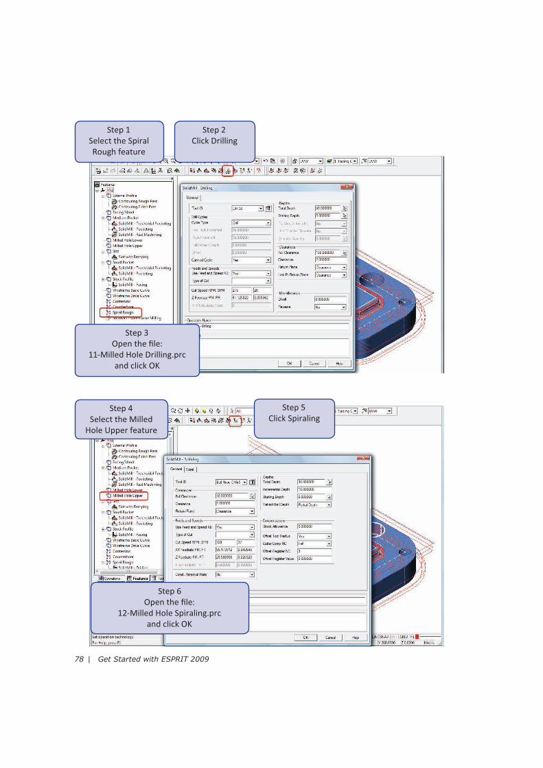
Pre-Dril l and Mill the Milled Hole
The milled hole has an upper diameter of 42mm and a lower diameter of 50mm. You will cut this
hole in three steps. First, you will pre-drill the hole with a 30mm drill. Then, you will create a
Spiraling opera�on to mill the upper diameter to a depth of 30mm. You will then create a bo&om
up Spiraling opera�on using a custom tool to mill the lower hole.
78 | Get Started with ESPRIT 2009
Step 1
Select the Spiral
Rough feature
Step 2
Click Drilling
Step 3
Open the file:
11-Milled Hole Drilling.prc
and click OK
Step 4
Select the Milled
Hole Upper feature
Step 5
Click Spiraling
Step 6
Open the file:
12-Milled Hole Spiraling.prc
and click OK
Project 2: Mill a Standard Part | 79
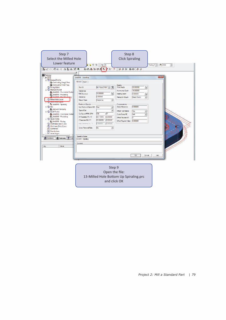
Step 7
Select the Milled Hole
Lower feature
Step 8
Click Spiraling
Step 9
Open the file:
13-Milled Hole Bo&om Up Spiraling.prc
and click OK
80 | Get Started with ESPRIT 2009
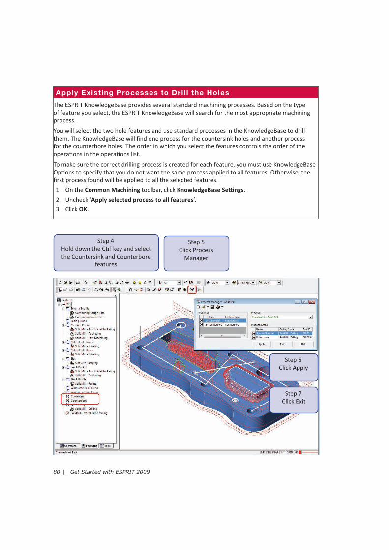
Apply Exist ing Processes to Dril l the Holes
The ESPRIT KnowledgeBase provides several standard machining processes. Based on the type
of feature you select, the ESPRIT KnowledgeBase will search for the most appropriate machining
process.
You will select the two hole features and use standard processes in the KnowledgeBase to drill
them. The KnowledgeBase will find one process for the countersink holes and another process
for the counterbore holes. The order in which you select the features controls the order of the
opera�ons in the opera�ons list.
To make sure the correct drilling process is created for each feature, you must use KnowledgeBase
Op�ons to specify that you do not want the same process applied to all features. Otherwise, the
first process found will be applied to all the selected features.
On the 1. Common Machining toolbar, click KnowledgeBase Se!ngs.
Uncheck ‘2. Apply selected process to all features’.
Click 3. OK.
Step 4
Hold down the Ctrl key and select
the Countersink and Counterbore
features
Step 5
Click Process
Manager
Step 6
Click Apply
Step 7
Click Exit
Project 2: Mill a Standard Part | 81
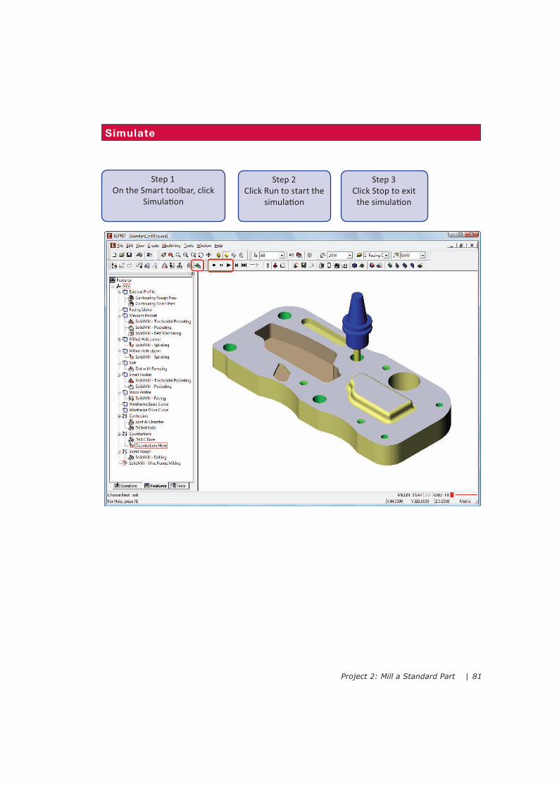
Simulate
Step 1
On the Smart toolbar, click
Simula�on
Step 2
Click Run to start the
simula�on
Step 3
Click Stop to exit
the simula�on
82 | Get Started with ESPRIT 2009
Create a Shop Floor ReportThe Report Generator creates HTML and PDF reports that detail the tools and opera�ons for any of
your part files. The preforma&ed reports are an important NC post processing tool and invaluable
shop floor resource. They provide the machining details required to correctly set up a machine and
perform the required machining opera�ons.
Reports contain informa�on about the machine, the tools, the part, opera�ons, and the NC
program. In addi�on, each page in the report displays a full-color image showing how the part
should look at each stage of the machining process.
Two types of standard reports are available: Summary and Detailed.
Summary Report
Basic informa�on about the machining process is provided on a single summary page. The
summary report contains a header with general informa�on about the program and an opera�on
list with one row per opera�on. Each row displays the main informa�on about the opera�on like
the opera�on name, the tool name, the tool ID, feeds and speed, and so on.
Detailed Report
This report provides the same summary page along with detailed pages for each opera�on and a
complete tool list. Click on an opera�on hyperlink in the summary page to access the opera�on
details. Click on a tool hyperlink to access the tool details. Opera�on report pages provide detailed
opera�on-specific informa�on such as the tool details and available cu"ng parameters.
Default Folders for Report Files
By default, report files are saved to your user folder under the ESPRIT\Data\ReportGenerator\
Reports directory, but you can change it to any other loca�on by clicking the Op�ons bu&on on the
Report Generator dialog.
Generated reports are saved to a subfolder in the distribu�on loca�on. The subfolder is always
named the same as your part file. If you regenerate any report, all files in the subfolder, including
any output from a previous report, are deleted. If you intend to save any previous version of a
report, copy it from the distribu�on folder before you regenerate the report.
Important: To use the Report Generator, your security key must be a&ached to your computer
and you must have a valid license. If you are running ESPRIT in demo mode, the Create Reports...
command is not available on the File menu.
Project 2: Mill a Standard Part | 83
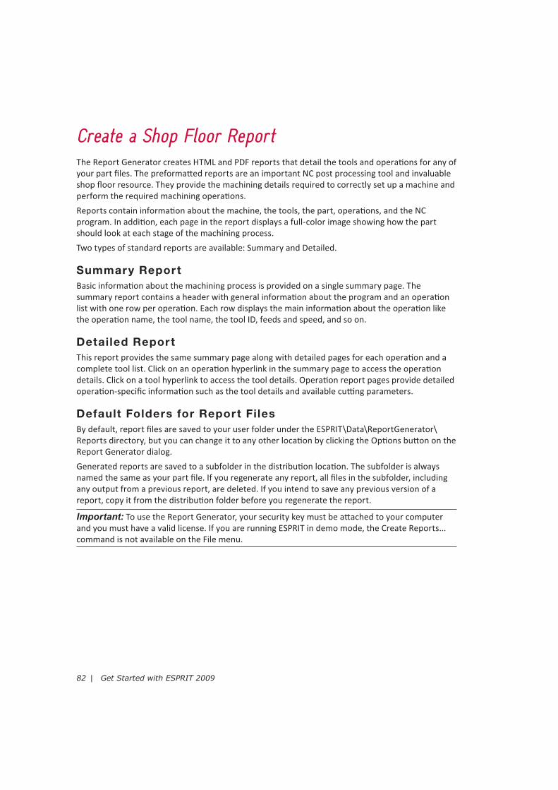
Step 1
On the File menu, click
Create Reports...
Step 2
Select Milling-Detailed, then click
Create Reports
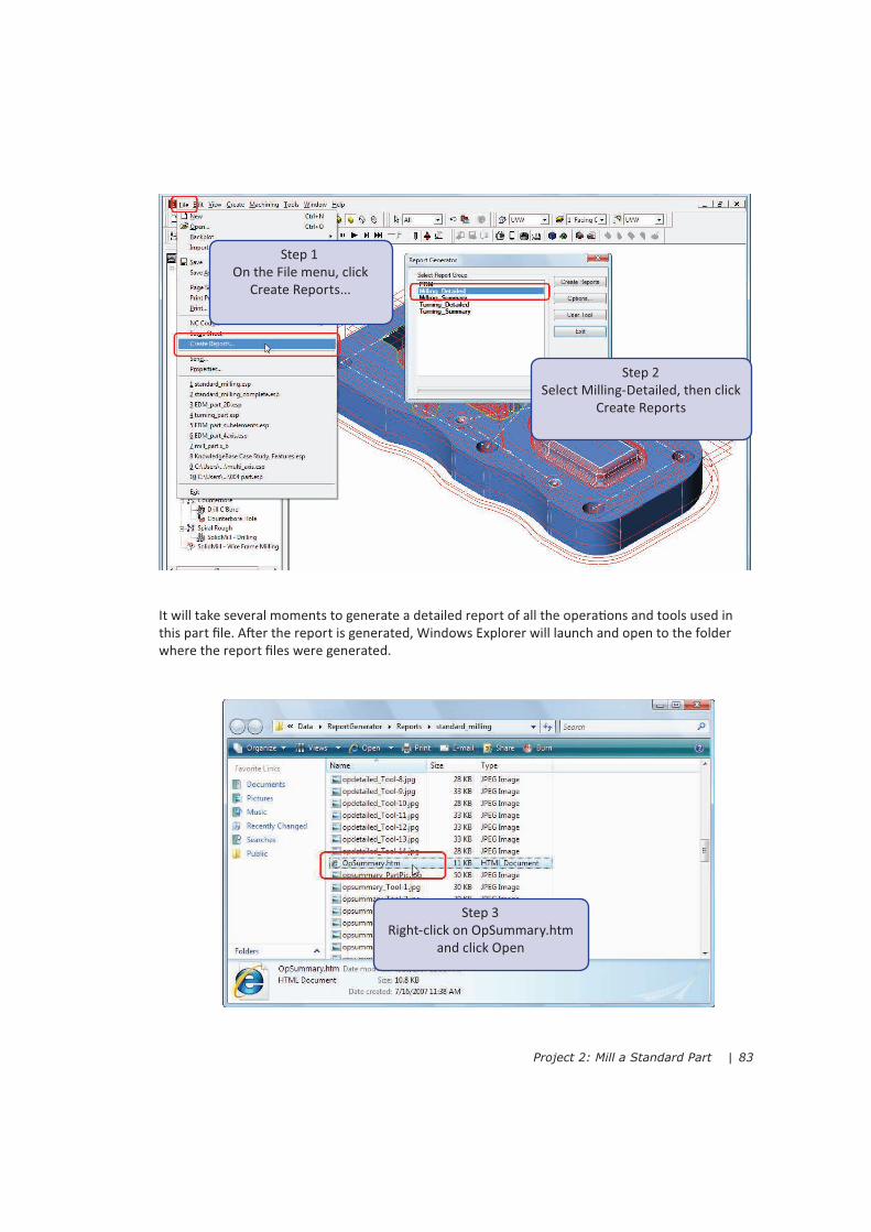
Step 3
Right-click on OpSummary.htm
and click Open
It will take several moments to generate a detailed report of all the opera�ons and tools used in
this part file. A%er the report is generated, Windows Explorer will launch and open to the folder
where the report files were generated.

84 | Get Started with ESPRIT 2009
Step 4
Click on a hyperlink to view the
opera�on or tool details


![MultidimensionalRankReductionEstimator forParametricMIMOChannelModels · 2017. 8. 28. · conventional ESPRIT algorithm [7] and the multidimen-sional ESPRIT (MD ESPRIT) algorithm](https://static.fdocuments.in/doc/165x107/60d81e8baa8017424c077cbf/multidimensionalrankreductionestimator-forparametricmimochannelmodels-2017-8-28.jpg)