ArduPilot manual (PDF version)api.ning.com/.../ArduPilot_2_Manual.pdfArduPilot manual (PDF version)

March 10, 2014
Dr. Andrew Rawicz
School of Engineering Science
Simon Fraser University
Burnaby, British Columbia
V5A 1S6
Re: ENSC 440 Design Specification for ASD: Air Surveillance Drones
Dear Dr. Rawicz,
Enclosed to this letter is a document containing our Design Specification for ASD: Air Surveillance Drones, describing an autonomous radio controlled surveillance aircraft. Our goal is to bring easy to use affordable autonomous drones for search and rescue operations, fire watch and other applications to the market.
In our design specifications, we will be outlining the information and specifications necessary for design process of the proof-of concept model. In addition, we will be indicating any future design improvements for the product even though they will not be implemented in our current stages of development. This document will allow our engineers and managers to follow the specified requirements and development activities when bringing the product into fruition.
Our company ASD was created by three dedicated engineering science students namely: Armin Samadanian, Juan Carlos Diaz and Afshin Nikzat. We thank you for considering our proposal and look forward to hearing from you. If you have any further questions please do not hesitate to contact us at [email protected].
Sincerely,
Armin Samadanian CEO Air Surveillance Drones

Design Specifications for Air Surveillance Drones Project Team:
Armin Samadanian
Afshin Nikzat
Juan Carlos Diaz
Contact person:
Armin Samadanian
Submitted to:
Dr. Andrew Rawicz - ENSC 440 Steve Whitmore - ENSC 305 School of Engineering Science
Issued Date: March 11, 2014
Revision: 1.0

Copyright © 2014, ASD III
Abstract
The Air Surveillance Drone is a product that ASD is developing to enhance the quality of aerial surveillance while bringing the cost of such operations down. ASD allows their users to program desired locations to be surveyed to the navigation system while allowing for manual control of the drone by an operator. The ASD reduces the concerns arising from current air surveillance drones on the market, such as environmental and economic requirements.
The design specification for the air Surveillance Drones illustrates the detailed processes for our proof-of-concept model. However, justification for our designs and future improvements of our models will be discussed. Our document will mainly be comprised of sections regarding the mechanical, hardware, embedded, and software designs. Test plans are provided and explained to ensure compliance each of ASD’s components.

Copyright © 2014, ASD IV
Table of Content
Abstract………………….......................................................................................................................... iii List of Figures...................................................................................................................................... v List of Tables........................................................................................................................................ v List of Equations……………………………………………….…………………………………………………... v Glossary………………………………………………………….……………………………………………………… vi 1. Introduction………………………………………………….…………………………………........................ 1
1.1 Scope……………………………………………………….…………………………....................... 1 1.2 Intended Audience………………………………………………………….………................. 1
2. System Specifications……………………………………………………….………………………………… 2 3. Mechanical Design………………………………………………………………………….…………………… 3
3.1 Designing an Airplane…………………………………………………………………………. 3 3.2 Propulsion......................................................................................................................
3
3.3 Vertical Performance and Airspeed…………………………………………………….. ....................................................................................................
4 3.4 Wings……………………………………………………….………………………………………….. 4 3.4.1 The Airfoil………………………………………………………….……………………. 4 3.4.2 Wing Loading…………………………………………………….………………….... 4 3.4.3 Aspect Ratio…………………….…………………………………….……………….. 5 3.4.4 Dihedral……………………………….………………………………………………… 5 3.4.5 Washout……………………………….…………………………………………...……. 5 3.4.6 Aileron/ Flaps…………………………….……………………………………….….. 5
3.4.7 Lay Out…………………………………….………………………………………………. 5 3.5 Construction Techniques………………………………………….……...………………….. 6 3.5.1 Balsa Wood………………………………….………………………………………….. 7 3.6 Propulsion……………………………….………………………………………...………………… 7 3.6.1 Electric……………………………………………………………….……………………. 7 3.7 Electrical Hardware Design………………………….…………………………………….… 7 3.7.1 Solar Cells………………………………………………………………………….….. 7 3.8 Main Power Supply……………………………………………………...…………………….….. 8 3.8.1 Power Design…………………………..………………………………………………. 8
3.9 Battery and Solar Cells……………………………………………...……………………………. 9 3.10 ArduPilot…………………………………….………………………...…………………………. 9 3.10.1 Ardupilot integrated 3-Axis Gyroscope……………………………….. …………………………………………………………………...
10 3.10.2 Ardupilot Integrated 3-Axis Accelerometer………………………... 10
3.10.3 Ardupilot Integrated 3-Axis Magnetometer…………………………. 11 3.10.4 Ardupilot Integrated Barometer………………………………………….. 11 3.10.5 Ardupilot Mission Planner ………………………………………………….. 12 3.11 GPS…………………………………………….…………….………………………………………. 12
3.12 Video System……………………………………………………………………………………. 12 3.13 Radio System…………………………………………………………………………………… 13 4. System test Plan………………………………………………………………………………………................. 13
4.1 GPS Module Test………………………………………..…………………………………………... 13 4.2 Compass Module Test………………………………………………………………………........ 14 4.3 Solar Cells and Battery Test…………………………………………………………………… 14 4.4 Plane Engine Test………………………………………………………………………................ 14
4.5 Video and Camera Test………………………………………………………………………...... 14
4.6 Software (PC Interface/Microcontroller implementation) Test…………..... 15
5. Conclusion………………………………………………………………………................................................ 15 6. References………………………………………………………………………................................................ 16
Appendix………………………………………………………………………………………................................... 17
Copyright © 2014, ASD V
List of Figures
Figure 2-1: ASD’s High-level Block Diagram
Figure 2-2: Drone control Block Diagram
Figure 2-3: ASD’s Mission operation Block Diagram
Figure 3.1: Airfoil Geometry, Symmetrical
Figure 3.2: Airfoil Geometry, Flat Bottom
Figure 3.3: Airfoil Geometry, Reflexed
Figure 3.4: Diagram of how to measure the wing dihedral
Figure 3.5: Lay out of a plane using the recommended ratios, based on a 10 unit wing span
Figure 3.6: CAD Design of the model plane
Figure 3.7: Solar Cells
Figure 3.8: Ardupilot Board without Protective Casing
Figure 3.9: Real-Time Data from ArduPilot 3-Axis Gyroscope using Mission Planner Software
Figure 3.10: Real-Time Data from ArduPilot 3-Axis Accelerometer using Mission Planner Software
Figure 3.11: Real-Time Data from ArduPilot 3-Axis Magnetometer using Mission Planner Software
Figure 3.12: Mission Planner Screenshot of an ASD Test Flight
List of Tables Table 3.1: this table Identifies which flight characteristics are affected by different Design Parameters
Table 3.1: Power Component Specifications
List of Equations Equation 3-1: Voltage Divider Formula
Equation 3-2: Power Dissipation of Voltage Regulator
Equation 3-3: Atmospheric pressure equation

Copyright © 2014, ASD VI
Glossary
RC: The use of radio signals to remotely control a device is called Radio-Controlled (RC). It is achieved by means of a handheld Radio transmitter to control the vehicle. FPV: First Person View is a technique to control RC devices from distance. This method gives the capability of controlling vehicles from farther distances by using a camera. The camera will provide a first person perspective view for pilot as if he were onboard. This is also known as Remote Person View (RPV). RF: Radio Frequency is a rate of oscillation that relates to frequency of the wave. RF is mainly used for wireless communications. FM: Frequency Modulation is a method used to encode and transmit information using signals. Then the modulated signal will be demodulated at destination and data will be extracted. GPS: Global Positioning System is a system to obtain location and time information anywhere on earth using satellite navigation system. SAR: Search And Rescue is when a person is in need of immediate aid with no awareness of their location. There are a few sub fields, such as mountain, ground, urban, combat and air/sea search and rescue. ESC: An electronic speed control or ESC is an electronic circuit with the purpose to vary an electric motor's speed, its direction and possibly also to act as a dynamic brake.
LCD: Liquid crystal display or LCD is a flat panel display, electronic visual display, or video display that uses the light modulating properties of liquid crystals. C2C: Cradle-to-cradle or C2C design is a biomimetic approach to the design of products and systems.

Copyright © 2014, ASD 1
1. Introduction
The ASD, Air Surveillance Drones, are solar powered planes with GPS capability and autopilot system
being developed for any situation that needs air surveillance. ASD provides an inexpensive and
environmentally friendly alternative to other air surveillance solutions while making it possible for
longer flights without interruption. The design specification describes the technical details for the design
of each component of the Air Surveillance Drones.
ASD drone’s chosen airframe is an airplane as it allows longer range flights compared to other airframes
such as helicopters or quad-copters. The drone features an autopilot system comprised of a modified
Arduino board and a GPS module. Control surface movement is achieved with the use of Futaba
servomotors. Commands are transmitted and received with the use of an FM Futaba radio system. Real-
time video is transmitted and received with the use of Boscam equipment due to its quality and low-cost.
1.1 Scope
This document provides in-depth technical aspects of each component of the ASD’s design. It will
appropriately correspond to the functional requirements provided by Functional Specification for ASD:
Air Surveillance Drones. As a result, the design details will provide a deeper understanding as to how the
functional requirements will be implemented. The design specification will only provide the technical
points of the proof-of-concept and prototype models; therefore, only the fundamental functional
requirements will be discussed.
1.2 Intended Audience
The design-specifications will be used and implemented by all members of ASD. It will allow for a
measure of the design progress during the development phase. Furthermore, this document becomes a
guideline for function implementation, which will ensure compliance between both design and
implementation phases. The testing of the product will also follow the procedures listed below as a final
evaluation.
Copyright © 2014, ASD 2
2. System Specifications
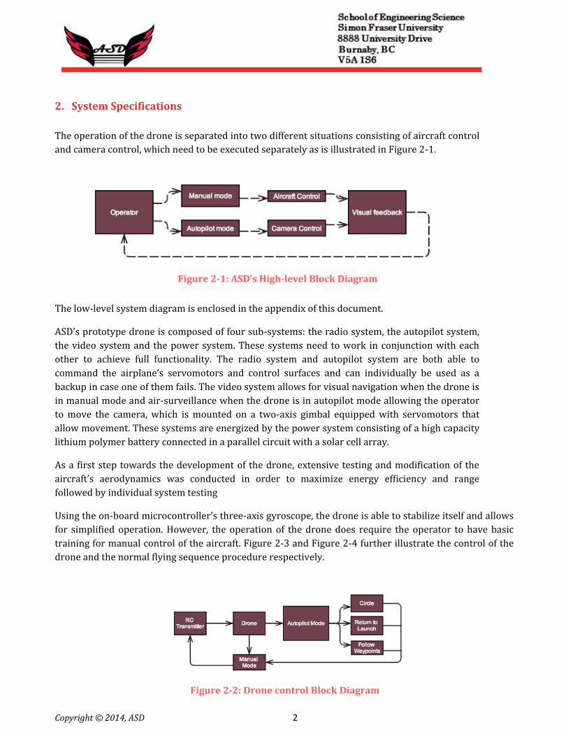
The operation of the drone is separated into two different situations consisting of aircraft control
and camera control, which need to be executed separately as is illustrated in Figure 2-1.
Figure 2-1: ASD’s High-level Block Diagram
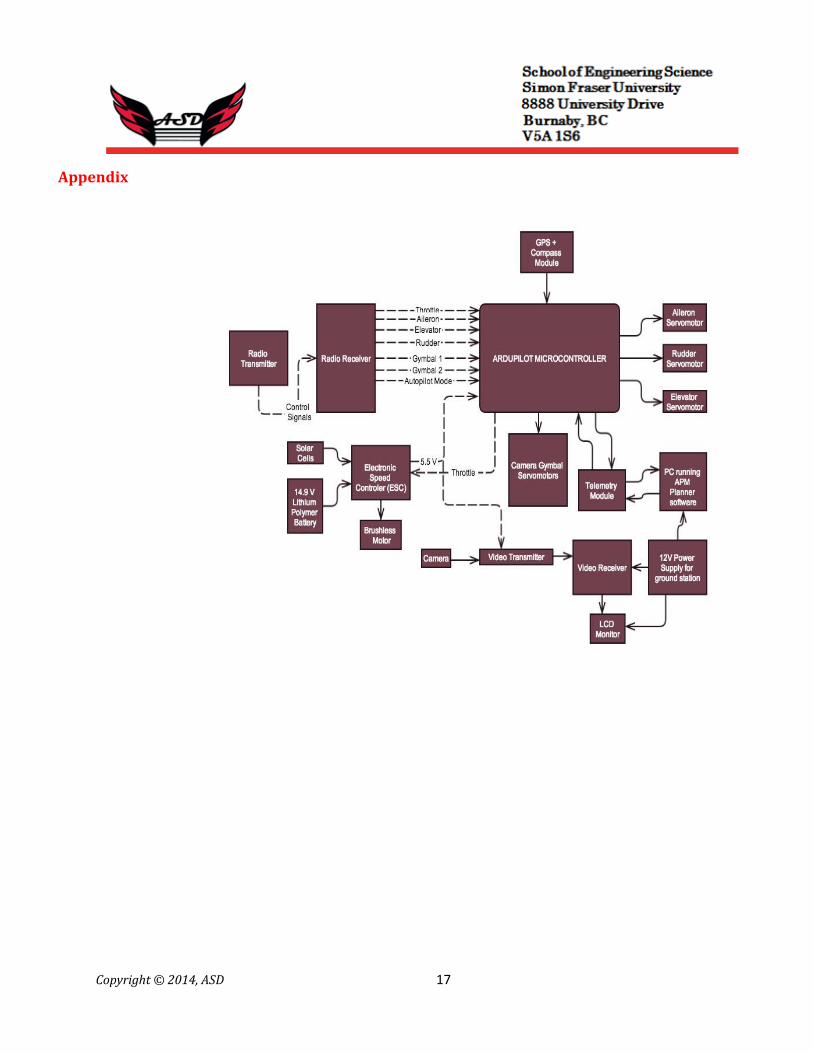
The low-level system diagram is enclosed in the appendix of this document.
ASD’s prototype drone is composed of four sub-systems: the radio system, the autopilot system,
the video system and the power system. These systems need to work in conjunction with each
other to achieve full functionality. The radio system and autopilot system are both able to
command the airplane’s servomotors and control surfaces and can individually be used as a
backup in case one of them fails. The video system allows for visual navigation when the drone is
in manual mode and air-surveillance when the drone is in autopilot mode allowing the operator
to move the camera, which is mounted on a two-axis gimbal equipped with servomotors that
allow movement. These systems are energized by the power system consisting of a high capacity
lithium polymer battery connected in a parallel circuit with a solar cell array.
As a first step towards the development of the drone, extensive testing and modification of the
aircraft’s aerodynamics was conducted in order to maximize energy efficiency and range
followed by individual system testing
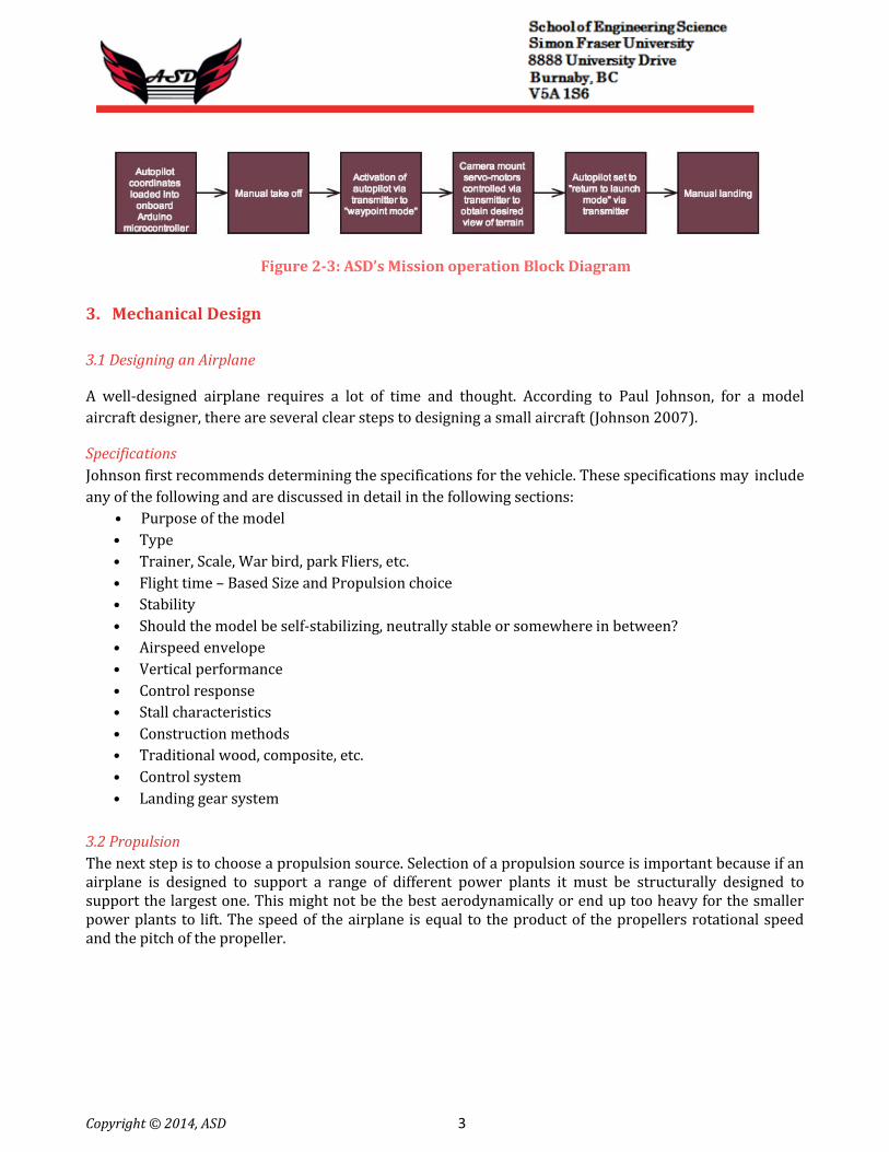
Using the on-board microcontroller’s three-axis gyroscope, the drone is able to stabilize itself and allows
for simplified operation. However, the operation of the drone does require the operator to have basic
training for manual control of the aircraft. Figure 2-3 and Figure 2-4 further illustrate the control of the
drone and the normal flying sequence procedure respectively.
Figure 2-2: Drone control Block Diagram
Copyright © 2014, ASD 3
Figure 2-3: ASD’s Mission operation Block Diagram
3. Mechanical Design
3.1 Designing an Airplane
A well-designed airplane requires a lot of time and thought. According to Paul Johnson, for a model
aircraft designer, there are several clear steps to designing a small aircraft (Johnson 2007). Specifications
Johnson first recommends determining the specifications for the vehicle. These specifications may include
any of the following and are discussed in detail in the following sections:
• Purpose of the model
• Type
• Trainer, Scale, War bird, park Fliers, etc.
• Flight time – Based Size and Propulsion choice
• Stability
• Should the model be self-stabilizing, neutrally stable or somewhere in between?
• Airspeed envelope
• Vertical performance
• Control response
• Stall characteristics
• Construction methods
• Traditional wood, composite, etc.
• Control system
• Landing gear system
3.2 Propulsion
The next step is to choose a propulsion source. Selection of a propulsion source is important because if an airplane is designed to support a range of different power plants it must be structurally designed to support the largest one. This might not be the best aerodynamically or end up too heavy for the smaller power plants to lift. The speed of the airplane is equal to the product of the propellers rotational speed and the pitch of the propeller.
Copyright © 2014, ASD 4
3.3 Vertical Performance and Airspeed
Step three is to determine the Vertical Performance and Airspeed. The rate of climb is a factor of the power plant, propeller being used, and the ready to fly weight. The propulsion source, propeller and wing design determine the airspeed. Both of these will affect the size and payload of the final airplane design. The rate of climb may be compromised in the final design to achieve the desired speed.
3.4 Wings
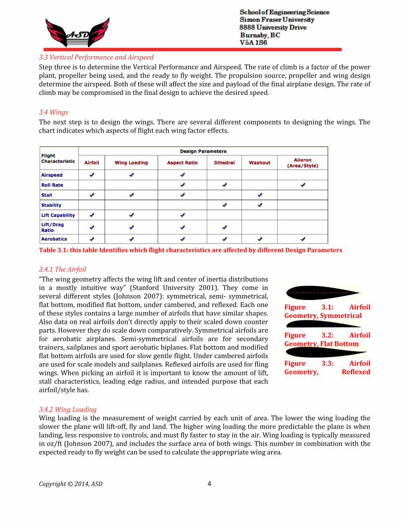
The next step is to design the wings. There are several different components to designing the wings. The chart indicates which aspects of flight each wing factor effects.
Table 3.1: this table Identifies which flight characteristics are affected by different Design Parameters
3.4.1 The Airfoil
“The wing geometry affects the wing lift and center of inertia distributions in a mostly intuitive way” (Stanford University 2001). They come in several different styles (Johnson 2007): symmetrical, semi- symmetrical, flat bottom, modified flat bottom, under cambered, and reflexed. Each one of these styles contains a large number of airfoils that have similar shapes. Also data on real airfoils don’t directly apply to their scaled down counter parts. However they do scale down comparatively. Symmetrical airfoils are for aerobatic airplanes. Semi-symmetrical airfoils are for secondary trainers, sailplanes and sport aerobatic biplanes. Flat bottom and modified flat bottom airfoils are used for slow gentle flight. Under cambered airfoils are used for scale models and sailplanes. Reflexed airfoils are used for fling wings. When picking an airfoil it is important to know the amount of lift, stall characteristics, leading edge radius, and intended purpose that each airfoil/style has.
Figure 3.1: Airfoil Geometry, Symmetrical
Figure 3.2: Airfoil Geometry, Flat Bottom
Figure 3.3: Airfoil Geometry, Reflexed
3.4.2 Wing Loading Wing loading is the measurement of weight carried by each unit of area. The lower the wing loading the slower the plane will lift-off, fly and land. The higher wing loading the more predictable the plane is when landing, less responsive to controls, and must fly faster to stay in the air. Wing loading is typically measured in oz/ft (Johnson 2007), and includes the surface area of both wings. This number in combination with the expected ready to fly weight can be used to calculate the appropriate wing area.
Copyright © 2014, ASD 5
3.4.3 Aspect Ratio
The aspect ratio is the ratio of the wingspan to its chord (or width). This ratio affects the roll rate, lift-to-drag ratio and pitch sensitivity. This means that it also affects fuel efficiency and the planes tendency to tip stall. However if the aspect ratio is too high it will have sluggish response to rolling and is easier to break. A well-designed airplane compromised between having a large aspect ratio and being less manoeuvrable, and having a low ratio that is twitchy and inefficient. A good aspect ratio to aim for is 5:1(Tim 2001).
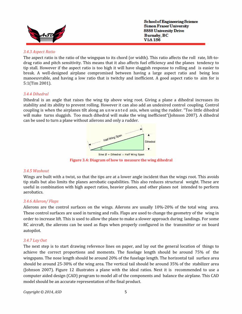
3.4.4 Dihedral
Dihedral is an angle that raises the wing tip above wing root. Giving a plane a dihedral increases its stability and its ability to prevent rolling. However it can also add an undesired control coupling. Control coupling is when the airplanes tilt along an u n w a n t e d axis, when using the rudder. “Too little dihedral will make turns sluggish. Too much dihedral will make the wing inefficient”(Johnson 2007). A dihedral can be used to turn a plane without ailerons and only a rudder.
Figure 3.4: Diagram of how to measure the wing dihedral
3.4.5 Washout
Wings are built with a twist, so that the tips are at a lower angle incident than the wings root. This avoids tip stalls but also limits the planes aerobatic capabilities. This also reduces structural weight. These are useful in combination with high aspect ratios, heavier planes, and other planes not intended to perform aerobatics. 3.4.6 Aileron/ Flaps
Ailerons are the control surfaces on the wings. Ailerons are usually 10%-20% of the total wing area.
These control surfaces are used in turning and rolls. Flaps are used to change the geometry of the wing in
order to increase lift. This is used to allow the plane to make a slower approach during landings. For some
RC aircraft, the ailerons can be used as flaps when properly configured in the transmitter or on board
autopilot.
3.4.7 Lay Out
The next step is to start drawing reference lines on paper, and lay out the general location of things to
achieve the correct proportions and moments. The fuselage length should be around 75% of the
wingspans. The nose length should be around 20% of the fuselage length. The horizontal tail surface area
should be around 25-30% of the wing area. The vertical tail should be around 35% of the stabilizer area
(Johnson 2007). Figure 12 illustrates a plane with the ideal ratios. Next it is recommended to use a
computer aided design (CAD) program to model all of the components and balance the airplane. This CAD
model should be an accurate representation of the final product.

Copyright © 2014, ASD 6
Figure 3.5: Lay out of a plane using the recommended ratios, based on a 10 unit wing span
Figure 3.6: CAD Design of the model plane
3.5 Construction Techniques
There are several different materials and techniques commonly used for building homemade aircrafts. Each of
these methods has their own unique advantages and disadvantages, and targeted application. Balsa wood is the
main material used in building of our prototype Drone.

Copyright © 2014, ASD 7
3.5.1 Balsa Wood
The advantages of working with a wood frame are that it requires only simple tools for construction and are
fairly inexpensive to build. They also don’t demand the close tolerances that other materials do. Considering the
size and weight of the aircraft the project calls for, balsa wood is a good choice. Balsa wood is light, readily
available, and cost efficient. Usually when constructing a wooden frame, the basic shape and air foils are
designed then modeled by a ribbed structure that will support the covering in the desired shape. These rips can
be cut out by hand or using a laser cutter then attached together using some type of epoxy or wood glue. Once
the frame is assembled it can then be covered in cloth, plastic or more wood. For full-scale aircrafts, like
personal airplanes, fabric made from high-grade polyester is usually used to cover the frame. However for small
crafts like UAVs and RC airplanes, fabric is simply too heavy for the amount of durability it provides. For lighter
planes, a plastic covering called Monokote is often used to cover the frame. Heat is applied to shrink it and seal
i t around the structure. For aircrafts that need a more durable covering, lightwood is sometimes used to cover
the structure. Wet wood is malleable enough to be warped around the frame while keeping its hardness when
re-dried. While wooden frames are easier to build and many times more cost effective, they are not nearly as
durable or reliable as other materials.
3.6 Propulsion
The three primary power sources for propulsion used in modern aircrafts of this size is electric motors, gas
engines, and glow engines. All of these systems have their own advantages and disadvantages, and but electric
motor was the most practical and compatible system for our situation. 3.6.1 Electric
Using an electric motor to power an airframe allows for an easy simple solution that requires minimal
maintenance. The biggest downside to this is the source of power. Electric motors rely on batteries that are
heavy. A typical setup would provide a flight time of around fifteen minutes. This flight time can be extended
with more batteries but it would make the plane heavier. Another option is using solar cells as an alternate
source of power to extend flight time. Using solar cells would address both weight issues and environmental
concerns. Therefore using solar cells is the best solution for our purpose.
3.7 Electrical Hardware Design
3.7.1 Solar Cells
Twenty 10 × 20 solar cells 3X6 .5V X 4 AMPS (2 WATTS each) in parallel will provide the power system with 20V of
voltage and 4 AMPs of current. That is the necessary power needed for the drone to run without the use of any
battery. This configuration will be used in a circuit where we have the solar cells in parallel with the battery. A
diode will be used between the battery and the solar cells to ensure no current will be flowing towards the battery
since any fluctuation in the power provided to battery can damage the battery.

Copyright © 2014, ASD 8
Figure 3.7: Solar Cells
3.8 Main Power Supply
3.8.1 Power Design
The purpose of having this priority list is to show what items can be turned off without losing functionality of the flight
of the plane for as long as possible.
System Voltage Current Allowed
Power
Priority level*
Camera 5 V .5 A 2.5 W 3
Video Transmitter 5 V 2 A 10 W 3
Video Receiver 5 V 2 A 10 W 3
FM Receiver 5 V .6 A 3 W 2
FM Transmitter 12 V 3 A 36 W 2
Autopilot System 5 V .5 A 4 W 1
Servos 5 V 3 A 15 W 1
Table 3.2: Power Component Specifications *priority goes from highest being 1 down to 4 the lowest
The battery outputs 14.8 volts to Electronic Speed Control system of the engine which in turn computes the necessary
voltages the motor needs to achieve a specific rotational velocity specified by the radio system. The Electronic Speed
Control also contains a voltge regulator that constantly outputs 5 volts to the ArduPilot board. Having the solars cells in
parallel with the battery provides an alternate source of power that can be used when enough solar energy is available
in order to extend the flight time. The ArduPilot provides the necessary power to the video transmitter, radio reciever,
the servo motors, the GPS module and the telemetry module. The maximum voltage output of the ArduPilot is 5V.
( ) Equation 3-1: Power Dissipation of Voltage Regulator
The ground station power system consists of a video monitor with the required input voltage of 12V and a video
receiver with the required input voltage of 5V. A 12-V motorcycle battery will power our ground-station. This battery
will be used to directly power our monitor and a voltage devider configuration will be used to provide the video reciever
with the necessary 5-V input.
Equation 3-2: Voltage Divider Formula

Copyright © 2014, ASD 9
3.9 Battery and Solar Cells
The battery needed for this system will have to be able to produce a continuous 34.5 Watts for the system to fully
operate. This was calculated using the worst case conditions, for example, stall condition for servos, then round up
to the nearest tenth of an amp just as a precaution. As for battery life, it will need to last for at least 25 minutes
based on our expected flight time. To meet the standards and to try to keep it as light as possible, a high capacity
lithium polymer battery will be used. Lithium Polymer batteries are commonly used in RC as the main power source
for planes. LiPo batteries have a high energy density and are moderately safe to handle and charge unlike lithium
Ion batteries (Barnard Microsystems Limited 2012). We will also use solar cells in parallel with the battery to
extend our flight time and meet the expected requirements. Solar cells will be used as an alternate source of power
that can be used for as long as available.
3.10 ArduPilot
ArduPilot is an open source autopilot project that runs on modified Arduino Megas, which are readily available
development microprocessor boards. It is one of the most versatile platforms as it allows control of diverse aerial
platforms such as airplanes, helicopters or quad-copters. Ardupilot is known for its simplicity and fully featured
ground station software as well as its expandability as it allows external modules to be connected such as GPS or
airspeed sensors. Ardupilot uses a telemetry module that transmits in the 800Mhz frequency band to any portable
computer or Android phone allowing real-time information to be displayed on the Mission Planner Software. Many
UAV research projects utilize ArduPilot (Bin et al, 2009) (Kabbabe et al, 2011) (Joseph et al, 2011).
Figure 3.8: Ardupilot Board without Protective Casing

Copyright © 2014, ASD 10
3.10.1 Ardupilot integrated 3-Axis Gyroscope
In order for the microprocessor board to correctly stabilize the aircraft, it needs to know the current orientation of the plane. By implementing a built-in 3-Axis Gyroscope, Ardupilot is able to correct or set the desired aircraft position by moving the servomotors and thus, changing the angles of the control surfaces.
Figure 3.9: Real-Time Data from ArduPilot 3-Axis Gyroscope using Mission Planner Software
3.10.2 Ardupilot Integrated 3-Axis Accelerometer
During manoeuvres, the aircraft experiences accelerations due to centripetal forces. Ardupilot uses this fact to its advantage by detecting these accelerations and using the data to control the corrections made to the control surfaces without causing the plane to overshoot. PID control gains for each specific airframe need to be loaded to the Ardupilot for correct functionality.
Figure 3.10: Real-Time Data from ArduPilot 3-Axis Accelerometer using Mission Planner Software

Copyright © 2014, ASD 11
3.10.3 Ardupilot Integrated 3-Axis Magnetometer
Knowing the orientation with respect to the magnetic poles of earth has been a crucial navigational tool for many centuries. Ardupilot can sense the magnetic fields of the earth in all three spatial axes using its built in magnetometer. Orientation relative to the earth’s magnetic field allows Ardupilot to create a parameter called heading, a term widely used in the aerospace industry. Knowing the heading of the aircraft is basic for the autopilot mode to guide the plane to a desired position correctly. Ardupilot uses its built-in 3-axis magnetometer combined with an external GPS module to achieve this purpose.
Figure 3.11: Real-Time Data from ArduPilot 3-Axis Magnetometer using Mission Planner Software
In figure 3.11 it is possible to appreciate a change in heading of the aircraft, the graph shows the raw data inputs obtained from the Mission Planner software. 3.10.4 Ardupilot Integrated Barometer
Unfortunately, current GPS technology is not very accurate when measuring altitude. Ardupilot addresses this issue by incorporating a built-in barometer that detects variations in atmospheric pressure to provide an estimate altitude relative to sea level and a more accurate relative altitude to the launch site. Launch site relative altitude readings are more accurate due to the fact that air temperature affects atmospheric pressure and since temperature does not vary very rapidly during the length of a drone’s mission, the readings are quite accurate in comparison with taking a specific pressure as reference to sea level as the value varies throughout the year. Atmospheric pressure is calculated with equation 3-3 where K is the Boltzmann’s constant, m is the mass of one air molecule, g is the accelerations due to gravity, T is the temperature in Kelvin degrees, is the pressure at the initial height, is the pressure at the final height and h is the vertical distance from the point in which and were measured. If initial and final pressures are known and assuming constant temperature, h can be solved and for our case h is the desired measurement of the drone’s altitude.
Equation 3-3: Atmospheric pressure equation

Copyright © 2014, ASD 12
3.10.5 Ardupilot Mission Planner Software
The software that accompanies the ArduPilot is called Mission Planner. With this software, it is possible to install the ArduPilot’s firmware for different airframes and it allows the specification of an extensive range of flight parameters that need to be adjusted according to each aircraft. The software also allows to set waypoints on a map for the drone to follow.
Figure 3.12: Mission Planner Screenshot of an ASD Test Flight
3.11 GPS
The global positioning system (GPS) utilizes satellites orbiting around the Earth to obtain the aircrafts position. A
GPS receiver can be placed on the drone to provide its position during flight and display it in real-time on a map
inside the Mission Planner as is shown by Figure YY. Furthermore, it is possible to calculate the drone’s velocity if
its change in position during a specific time interval is known. GPS modules are implemented on many different
unmanned aerial research projects (Am et al, 2007) (Abdelkrim et al, 2008) (Chang-Sun et al, 2003).
3.12 Video System
The video system is comprised of a video transmitter and receiver on the 2.4 GHz band as well as an LCD display
and a high sensitivity video camera. The components selected for the project are the Boscam TS321 transmitter and
a Boscam RC802 receiver that can output the received video signal in NTSC format to a generic 10“ LCD display.
Transmitting at this high frequency minimizes interference that could be caused by the ArduPilot’s telemetry
module or the Radio System that use a separate part of the RF spectrum.
Copyright © 2014, ASD 13
3.13 Radio System
The radio system is comprised of a 9-channel FM transmitter an 8-channel FM receiver on the 72MHz band. FM allows signals to travel further in comparison with 2.4 GHz but is subject to interference from unforeseen sources. In case failure occurs, ArduPilot will automatically return the plane to the launch site.
4 System test Plan
In order to provide products of the utmost quality, each component and subsystem will be rigorously tested to ensure that they meet functional specifications. We will be analyzing the hardware signals of each subsystem to ensure that they are up to specifications. Each element of the subsystems will be tested for its integrity, functionality, and power consumption. During the development of the prototype, we will test the implementation between the software and hardware systems. In addition, we will also validate the physical properties of the device such as its ability to handle different kinds of stress, temperature, and environmental conditions. The tests listed must be passed multiple times during different phases of the development cycle.
4.1 GPS Module Test
The GPS module will be tested to ensure that it is able to precisely and timely obtain the longitude and latitude coordinates of the Drone. The serial communication lines used to interface with the microcontroller will also be analyzed to ensure signal integrity. Testing of the GPS module includes, but is not limited to:
● Measuring the time it takes the GPS to acquire the satellite signals
● Measuring the accuracy of the Drone’s coordinate
● Ensuring the GPS transmits the serial data accurately during processing
● Testing the strength of the signal in different weather conditions
● Ensuring that the GPS module does not have interference with other device

Copyright © 2014, ASD 14
3.1 Compass Module Test
The compass module (composing of the magnetometer) will be tested for its accuracy. The module’s tilt
compensation must also be tested for proper implementation. Testing of the compass module includes,
but is not limited to:
● Measuring the accuracy of the compass
● Ensuring that the directional data is transmitted quickly to the microprocessor
● Testing for the potential disruptions caused by external magnetic forces
3.2 Solar Cells and Battery Test
The solar cells will be tested to ensure it meets safety standards while providing a reliable source of
power. These solar cells will be implemented into the drone by placing them on the wings. The back-up
battery will be tested to ensure that it provides 30 minutes of continuous usage as outlined in the
requirements. Testing of the battery and the solar cells includes, but is not limited to:
● Measuring the device’s power consumption to see how much of usage can be extracted
from battery
● Testing the battery in conjunction with solar cells to ensure compatibility.
● Ensuring the back-up battery system will start powering the drone when there is no power provided by solar cells.
● Ensuring the solar cells and battery system are weather proof.
● Measuring the time required to fully recharge the battery.
3.3 Plane Engine Test
The engine will be tested to ensure it is powerful enough to operate the drone while being power
efficient at the same time. Testing of the engine includes, but is not limited to:
● Ensuring the mechanical housing of the engine is strong enough to protect it from
vibration shocks and from weather conditions.
● Testing of the amount of power the engine needs per unit time. ● Measuring the power the engine produces.

Copyright © 2014, ASD 15
3.4 Video and Camera Test The video and camera system will be tested to ensure the q u a l i t y of the video it produces. It will also be tested for its performance in different weather and light conditions. Testing of the engine includes, but is not limited to:
4.4.1 Camera testing
4.4.2 Quality of Video tests
4.4.3 Ensuring the weather and light conditions has minimal effect on the performance of our camera system
4.4.4 Compatibility tests
4.5 Software (PC Interface/Microcontroller implementation) Test
All parts of the software will include tests to ensure proper functionality; ease of use and response
to various mapping inputs. Testing of the software includes, but is not limited to:
4.5.1 Autopilot testing
4.5.2 Point of interest and path planning accuracy tests 4.5.3 Usability tests and analysis of the GUI
4.5.4 Platform testing
4.5.5 Compatibility tests
5 Conclusion
The design specifications listed in this document detail how the functional specifications of the ASD are to be fulfilled as well as having explained the implementation and current functionality of each subcomponent (hardware and software) of the device. The test plan will help to ensure that the design specifications are met and that product is in working order. The model is currently being developed and we expect to have a fully functional aircraft by the first week of April, 2013.

Copyright © 2014, ASD 16
6 References
Garcia, Esteban Gonzalez.; Becker, John. (2007) “UAV stability derivatives estimation for hardware-in- the-loop
simulation of Piccolo autopilot by qualitative flight testing” 1st Latin American UAV Conference. [online]
Available: http://www.aerodreams-uav.com/docs/aeroduav-conf.pdf
Am Cho; Jihoon Kim; Sanghyo Lee; Sujin Choi; Boram Lee; Bosung Kim; Noha Park; Dongkeon Kim; Changdon Kee.(
2007 Oct.). "Fully automatic taxiing, takeoff and landing of a UAV using a single- antenna GPS receiver only," Control,
Automation and Systems, 2007. ICCAS '07. International Conference on. [Online], vol., no., pp.821-825, 17-20 doi:
10.1109/ICCAS.2007.4407014
Available: http://ieeexplore.ieee.org/stamp/stamp.jsp?tp=&arnumber=4407014&isnumber=4406493 Abdelkrim, N.; Aouf, N.; Tsourdos, A.; White, B. (2008 June) "Robust nonlinear filtering for INS/GPS UAV
localization," Control and Automation, 2008 16th Mediterranean Conference. [online] vol., no., pp.695-702, 25-27
doi: 10.1109/MED.2008.4602149 Available: http://ieeexplore.ieee.org/stamp/stamp.jsp?tp=&arnumber=4602149&isnumber=4601965
Barnard Microsystems Limited .(2012).High Energy Light Weight Batteries(first)[Online].
Available: http://www.barnardmicrosystems.com/L4E_batteries.htm
Kabbabe, Kristopher. (2011) “Development of Procedures for Flight Testing UAVs using the ArduPilot System”.
[online]
Available: http://uavs.mace.manchester.ac.uk/uploads/Research/MScKabbabe2011.pdf Joseph, Lum Yue Hao. (2011) “Unmanned Aerial Vehicle Autopilot System”. [online]
Available: http://dynamicslab.mpe.nus.edu.sg/dynamics/thesis1011/UAV%20Autopilot.pdf
Chang-Sun Yoo; Iee-Ki Ahn; (2003 Oct.), "Low cost GPS/INS sensor fusion system for UAV navigation," Digital
Avionics Systems Conference, 2003. DASC '03. The 22nd , [online] vol.2, no., pp. 8.A.1- 8.1-9 vol.2, 12-16 doi:
10.1109/DASC.2003.1245891
Available: http://ieeexplore.ieee.org/stamp/stamp.jsp?tp=&arnumber=1245891&isnumber=27920
N.p., n.d. (2013 Mar.), "The Barometric Formula." The Barometric Formula. Web. Available: http://hyperphysics.phy-astr.gsu.edu/hbase/kinetic/barfor.html#c1
Copyright © 2014, ASD 17
Appendix