ESD & Safety requierments for Power via MDI - IEEE · PDF fileAssociated with Safety and ESD...
22
1 IEEE 802.3af DTE Power via MDI Can Electronic Components Survive the High Voltages Associated with Safety and ESD Immunity Tests? Proposal By PowerDsine: Avinoam Levy - [email protected] Rick Frosch - [email protected]
Transcript of ESD & Safety requierments for Power via MDI - IEEE · PDF fileAssociated with Safety and ESD...

1
IEEE 802.3af DTE Power via MDICan Electronic Components Survive the High Voltages Associated with Safety and ESD Immunity Tests?
Proposal By PowerDsine: Avinoam Levy - [email protected] Rick Frosch - [email protected]

2A. Levy, R. Frosch - PowerDsine
IEEE 802.3af September , 2000
YES!!!

3A. Levy, R. Frosch - PowerDsine
IEEE 802.3af September , 2000
High Voltage Related Safety Standards RequirementsEN60950, UL1950
! 3KVrms dielectric strength test, from AC input to RJ-45
! 500Vrms dielectric strength test, output to chassis
! Tests performed when unit is not operating
! These are standard requirements for off-line of the shelf power-supplies.
! Meeting these requirements will not impose real stress on the outputs of the PSE.

4A. Levy, R. Frosch - PowerDsine
IEEE 802.3af September , 2000
High Voltage Related ESD Standard Requirements IEC-61000-4-2
! Up to 15KV charged on a human body simulated network - capacitor in series to resistor.
! The standard provides guidelines to select the appropriate class and hence the voltage level.
! Pass criteria - defined by user, typically we design the equipment to survive with no performance degradation.

5A. Levy, R. Frosch - PowerDsine
IEEE 802.3af September , 2000
Examples of Silicon Components Used in Similar Conditions and Applications
! SLIC Ic’s (Subscriber Line Interface Card)
! Telephone Ring Generators
! Solid state relays used in telephony circuits
! Phone Ic’s.
! Many more
6A. Levy, R. Frosch - PowerDsine
IEEE 802.3af September , 2000
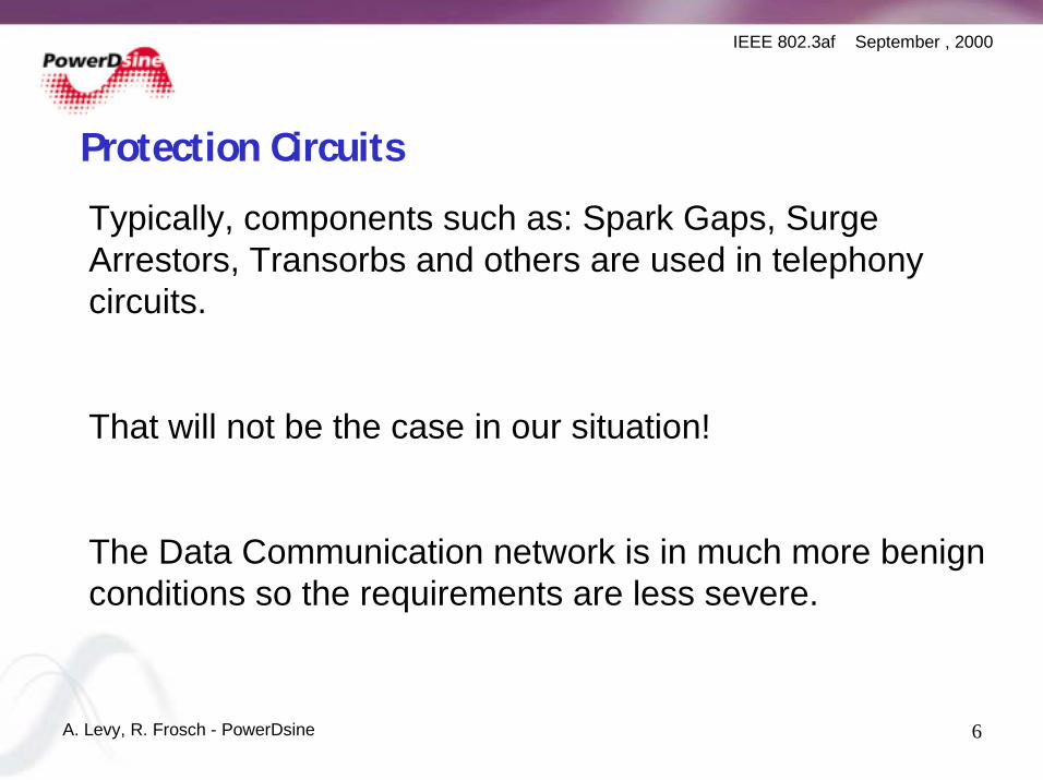
Protection Circuits
Typically, components such as: Spark Gaps, Surge Arrestors, Transorbs and others are used in telephony circuits.
That will not be the case in our situation!
The Data Communication network is in much more benign conditions so the requirements are less severe.

7A. Levy, R. Frosch - PowerDsine
IEEE 802.3af September , 2000
What are the Standard RequirementsESD Generator

8A. Levy, R. Frosch - PowerDsine
IEEE 802.3af September , 2000
Voltage Levels

9A. Levy, R. Frosch - PowerDsine
IEEE 802.3af September , 2000
Pulse Current Shape

10A. Levy, R. Frosch - PowerDsine
IEEE 802.3af September , 2000
Application Method
! Direct/Indirect discharge on accessible metal parts
! Indirect discharge on the accessible isolated parts
! Horizontal coupling plane
! Vertical coupling plane
In general, the direct discharge method is recommended, as it is more repetitive than air discharge.

11A. Levy, R. Frosch - PowerDsine
IEEE 802.3af September , 2000
How do these Pulses Impact the Design?
CB
CB
CA
12345678
RJ4
5
Typical ValuesCA - 0.1 to 10 microFCB - 4.7 to 47nF
Discovery Circuit& Power SupplyOutput
TYPICAL OUTPUT STAGE, PSE.
1
2

12A. Levy, R. Frosch - PowerDsine
IEEE 802.3af September , 2000
What do we have here?
Equivalent circuit for discharge on point 1or 2
SWITCH CLOSE ATt=0
CA
CB
CB
150pFV=2000V
330 OHM
1/2
Assuming:
CA= 0.47µFCB= 0.0047µFAs CA>> CBCA+ CB = CBTotal capacitance afterswitch close is ≅ 2CB

13A. Levy, R. Frosch - PowerDsine
IEEE 802.3af September , 2000
Some calculations...We know that:
Q @ t = 0- = Q @ t = 0+
CVQ *= ⇒ 2211 VCVC ∗=∗TOTAL CHARGE IN THE SYSTEM BEFORE DISCHARGE EQUAL TO CHARGE AFTERDISCHARGE.
Where: C1=150pF, C2=2CB, V1=V@t=0-=VS=2KV and V2=V1/2@t=0+
⇒ V1/2 @ t = 0+ = 32V ⇒ V1/2 is the voltage developed on the contact point
(can be point 1 or 2 on the system schematics),referenced to the chassis.
For V @ t = 0- = 8KV, V1/2 @ t = 0+ = 127V

14A. Levy, R. Frosch - PowerDsine
IEEE 802.3af September , 2000
Some more numbers...
Replacing CB to 10nF will reduce the developed voltage by 50%
As the charge is on the CB and CA branch is equal on both capacitors, the voltage across these two capacitors will be reveres proportional to its values. In our case, the voltage on CA - the cross output capacitor will be roughly 10% of the calculated voltage.

15A. Levy, R. Frosch - PowerDsine
IEEE 802.3af September , 2000
Let’s add Real Life Conditions
Switch close at t=0
CA
CB
CB
150pFVs
330 Ohm
ESRA+B
ESRBESLA+B
ESLB
Ll
Typical valuesESL - few nH to tens of nH
ESR - few mOhms to tens of mOhms
For the simulation, we assumed:
ESL=20nH for all caps
ESR=5mOhm for the ceramics, 20mOhm for the film cap.
Lr = 10nHy - or 500nHy (Bid?)
Vs = 8KV (class3)

16A. Levy, R. Frosch - PowerDsine
IEEE 802.3af September , 2000
Simulation Results - Spice Model
17A. Levy, R. Frosch - PowerDsine
IEEE 802.3af September , 2000
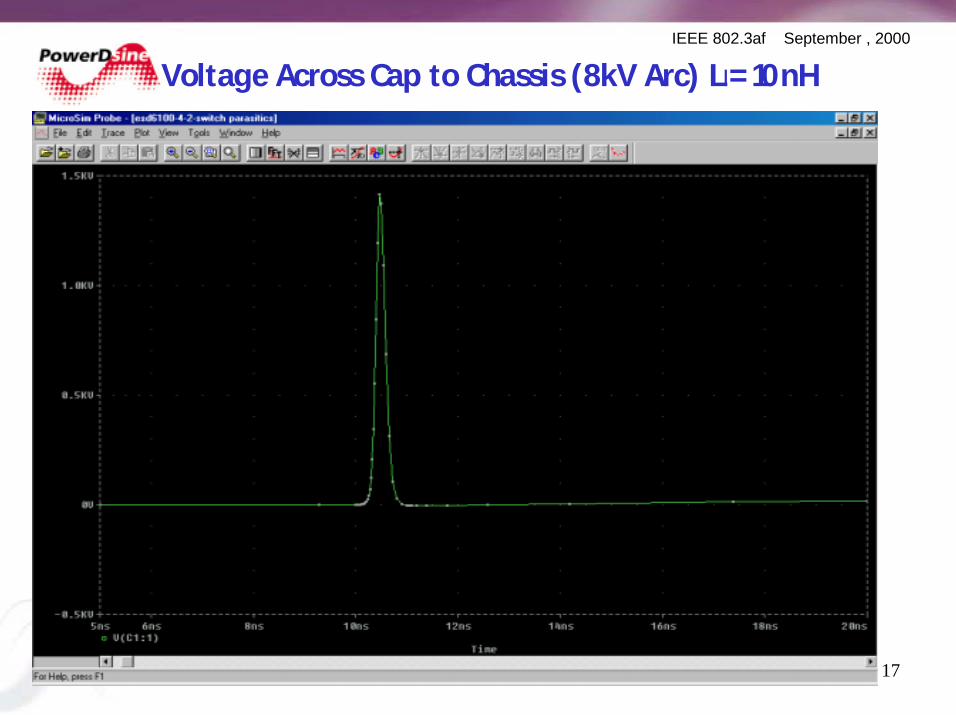
Voltage Across Cap to Chassis (8kV Arc) LI= 10nH

18A. Levy, R. Frosch - PowerDsine
IEEE 802.3af September , 2000
Voltage Across Input Cap (8kV Arc) LI = 10nH
19A. Levy, R. Frosch - PowerDsine
IEEE 802.3af September , 2000
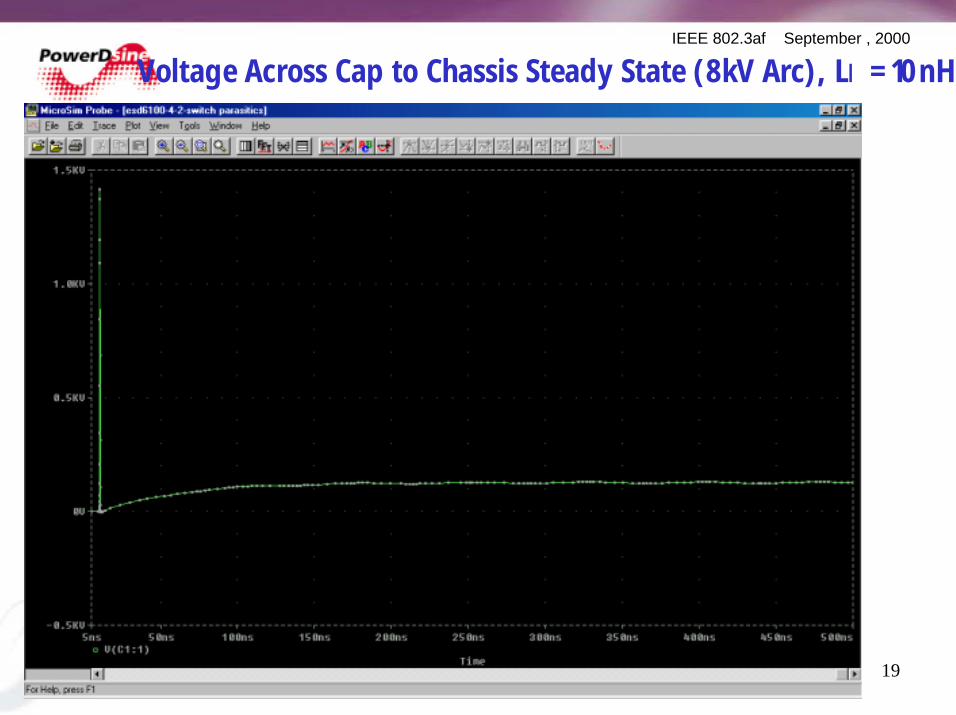
Voltage Across Cap to Chassis Steady State (8kV Arc), LI = 10nH
20A. Levy, R. Frosch - PowerDsine
IEEE 802.3af September , 2000
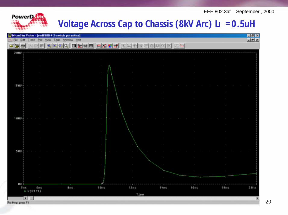
Voltage Across Cap to Chassis (8kV Arc) LI = 0.5uH

21A. Levy, R. Frosch - PowerDsine
IEEE 802.3af September , 2000
Voltage Across Input Cap (8kV Arc) LI = 0.5uH
22A. Levy, R. Frosch - PowerDsine
IEEE 802.3af September , 2000
Conclusions
! The presentation showed that with typical power supply and typical feeding port elements the voltage stresses on the PSE components are within manageable limits.
! Some basic design guidelines where given to enable meeting Electro-Static-Discharge.
! Isolation transformer is not a must for a reliable PSE unit that will not degrade the ESD immunity of the network.
! A well protected and robust design is also economically feasible.